Cambridge Azur 340A Int Sm
21
Gallery Court Hankey Place London SE1 4BB UK Tel: +44 (0)20 7940 2200 Fax: +44 (0)20 7940 2233 34 A Issue Date: 18 th June 2004 ______________________ ___________ ______ SERVICE MANUAL __________ SPECIFICATIONS: Power Output 40W (into 8 Ω) 50W (into 4Ω) Max Power Consumptio n 345W Total Harmonic Distortion 1kHz < 0.009% 20kHz < 0.09% Frequency Response (-1dB) 5Hz – 50kHz S to N Ration (unweighted) 99dB Slew Rate (into 8Ω) 20V/uS Dimensions (HxWxD) mm 70 x 430 x 310 Inches 2.8 x 16.9 x 12.2 Weight Kg 6.2 Lbs 13.6 AP15844/1 1
-
Upload
davidegazzini -
Category
Documents
-
view
236 -
download
0
Transcript of Cambridge Azur 340A Int Sm
7/23/2019 Cambridge Azur 340A Int Sm
http://slidepdf.com/reader/full/cambridge-azur-340a-int-sm 1/21
Gallery Court Hankey Place London SE1 4BB UKTel: +44 (0)20 7940 2200 Fax: +44 (0)20 7940 2233
34 A
Issue Date: 18th June 2004
________________________________________________________________________
SERVICE MANUAL
________________________________________________________________________
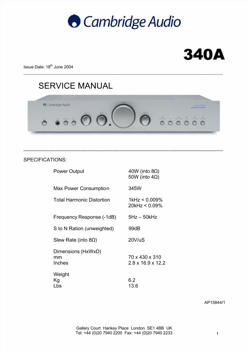
SPECIFICATIONS:
Power Output 40W (into 8Ω)50W (into 4Ω)
Max Power Consumption 345W
Total Harmonic Distortion 1kHz < 0.009%20kHz < 0.09%
Frequency Response (-1dB) 5Hz – 50kHz
S to N Ration (unweighted) 99dB
Slew Rate (into 8Ω) 20V/uS
Dimensions (HxWxD)mm 70 x 430 x 310Inches 2.8 x 16.9 x 12.2
WeightKg 6.2Lbs 13.6
AP15844/1
1
7/23/2019 Cambridge Azur 340A Int Sm
http://slidepdf.com/reader/full/cambridge-azur-340a-int-sm 2/21
340A SERVICE MANUAL
TABLE OF CONTENTS
Safety Precautions & Important Notes 3
Main Assembly BOM 4/5
Micro controller PCB Schematic (PIC’s/Switches/LED’s) 6
Micro controller PCB Layout (Top Side) 7
Micro controller PCB Layout (Bottom Side) 8
Front Panel PCB Assembly BOM 9
Main PCB Schematic (Input Select) 10
Main PCB Schematic (Power Amplifiers) 11
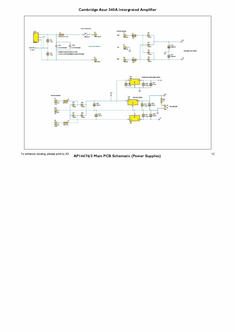
Main PCB Schematic (Power Supplies) 12
Main PCB Schematic (Tone Control) 13
Main PCB Layout (Top Side) 14
Main PCB Layout (Bottom Side) 15
Main PCB BOM 16-18
IC Pin Layout Details 19/20
Silver – Black Differences BOM 21
2
7/23/2019 Cambridge Azur 340A Int Sm
http://slidepdf.com/reader/full/cambridge-azur-340a-int-sm 3/21
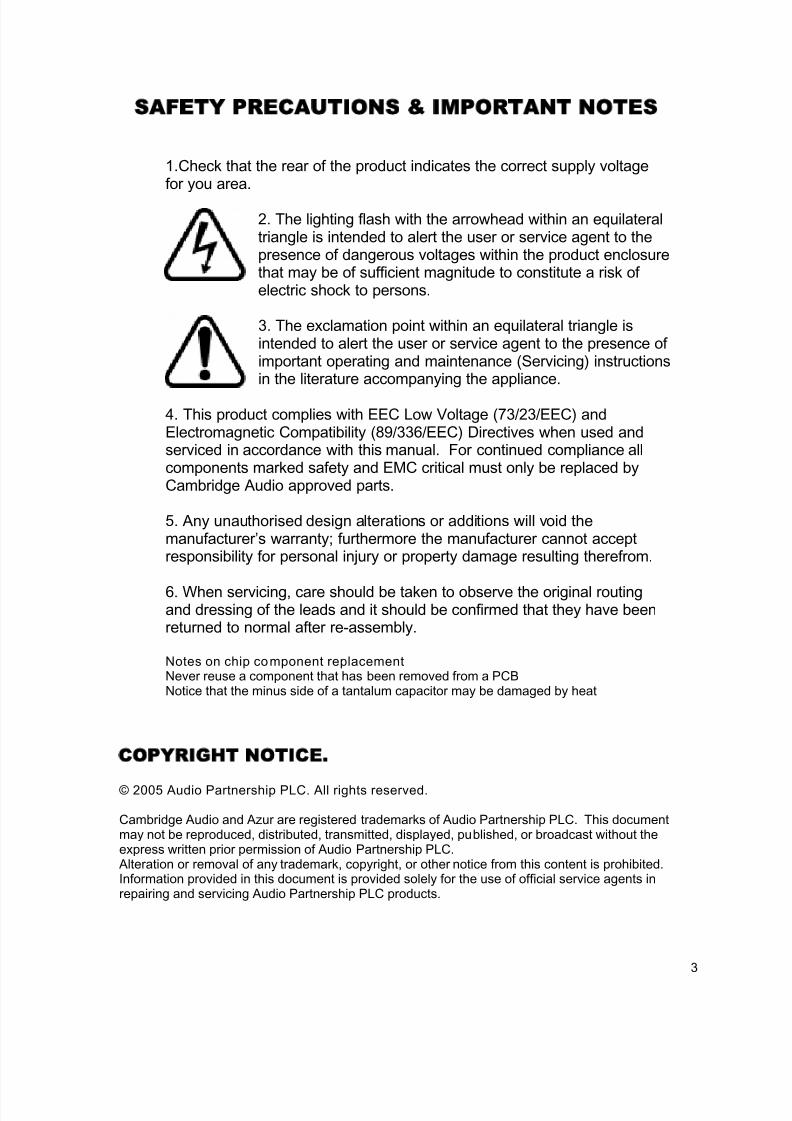
SAFETY PRECAUTIONS IMPORTANT NOTES
1.Check that the rear of the product indicates the correct supply voltagefor you area.
2. The lighting flash with the arrowhead within an equilateraltriangle is intended to alert the user or service agent to thepresence of dangerous voltages within the product enclosurethat may be of sufficient magnitude to constitute a risk ofelectric shock to persons.
3. The exclamation point within an equilateral triangle isintended to alert the user or service agent to the presence ofimportant operating and maintenance (Servicing) instructionsin the literature accompanying the appliance.
4. This product complies with EEC Low Voltage (73/23/EEC) andElectromagnetic Compatibility (89/336/EEC) Directives when used andserviced in accordance with this manual. For continued compliance allcomponents marked safety and EMC critical must only be replaced byCambridge Audio approved parts.
5. Any unauthorised design alterations or additions will void themanufacturer’s warranty; furthermore the manufacturer cannot acceptresponsibility for personal injury or property damage resulting therefrom.
6. When servicing, care should be taken to observe the original routingand dressing of the leads and it should be confirmed that they have beenreturned to normal after re-assembly.
Notes on chip component replacementNever reuse a component that has been removed from a PCBNotice that the minus side of a tantalum capacitor may be damaged by heat
COPYRIGHT NOTICE.
© 2005 Audio Partnership PLC. All rights reserved.
Cambridge Audio and Azur are registered trademarks of Audio Partnership PLC. This documentmay not be reproduced, distributed, transmitted, displayed, published, or broadcast without theexpress written prior permission of Audio Partnership PLC.
Alteration or removal of any trademark, copyright, or other notice from this content is prohibited. Information provided in this document is provided solely for the use of official service agents inrepairing and servicing Audio Partnership PLC products.
3
7/23/2019 Cambridge Azur 340A Int Sm
http://slidepdf.com/reader/full/cambridge-azur-340a-int-sm 4/21
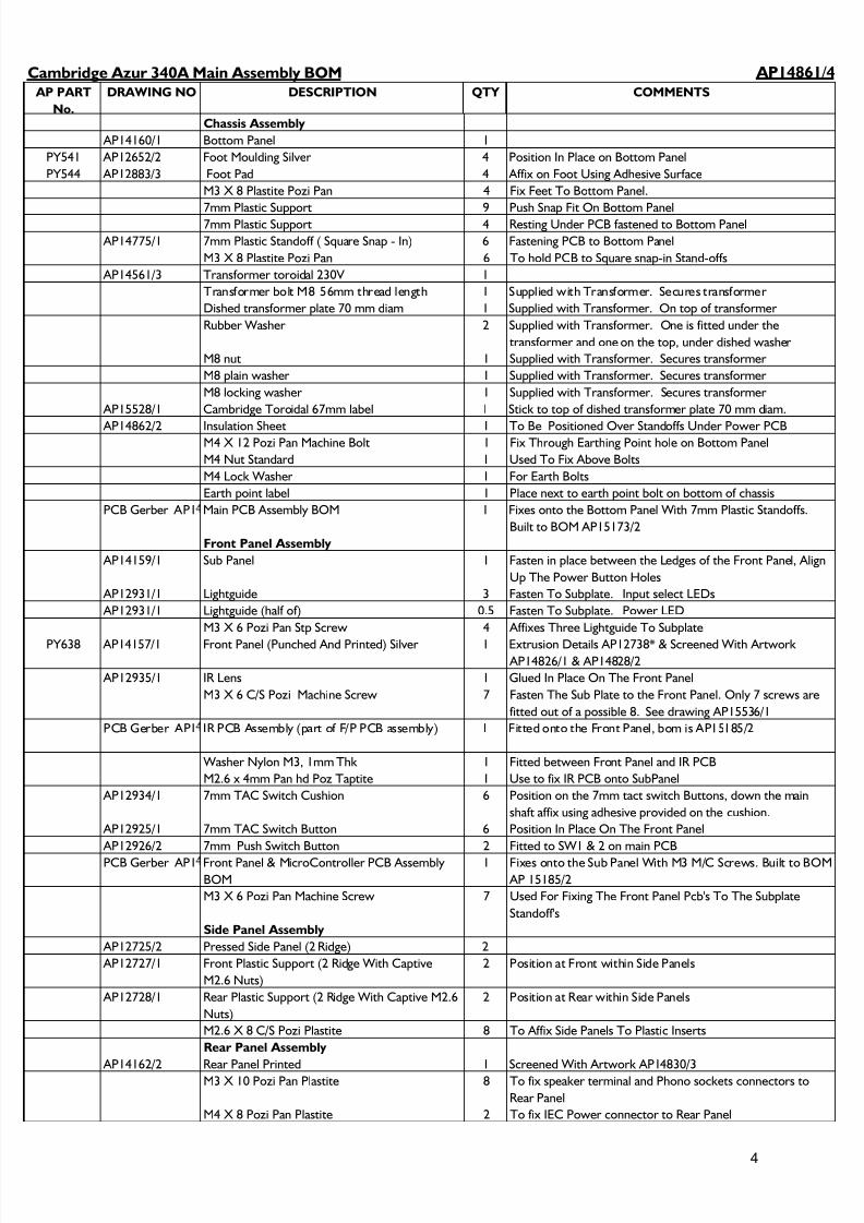
AP14861/4
AP PART
No.
DRAWING NO DESCRIPTION QTY COMMENTS
Chassis Assembly
AP14160/1 Bottom Panel 1
PY541 AP12652/2 Foot Moulding Silver 4 Position In Place on Bottom Panel
PY544 AP12883/3 Foot Pad 4 Affix on Foot Using Adhesive Surface
M3 X 8 Plastite Pozi Pan 4 Fix Feet To Bottom Panel.
7mm Plastic Support 9 Push Snap Fit On Bottom Panel7mm Plastic Support 4 Resting Under PCB fastened to Bottom Panel
AP14775/1 7mm Plastic Standoff ( Square Snap - In) 6 Fastening PCB to Bottom Panel
M3 X 8 Plastite Pozi Pan 6 To hold PCB to Square snap-in Stand-offs
AP14561/3 Transformer toroidal 230V 1
Transformer bolt M8 56mm thread length 1 Supplied with Transformer. Secures transformer
Dished transformer plate 70 mm diam 1 Supplied with Transformer. On top of transformer
Rubber Washer 2 Supplied with Transformer. One is fitted under the
transformer and one on the top, under dished washer
M8 nut 1 Supplied with Transformer. Secures transformer
M8 plain washer 1 Supplied with Transformer. Secures transformer
M8 locking washer 1 Supplied with Transformer. Secures transformer
AP15528/1 Cambridge Toroidal 67mm label 1 Stick to top of dished transformer plate 70 mm diam.
AP14862/2 Insulation Sheet 1 To Be Positioned Over Standoffs Under Power PCBM4 X 12 Pozi Pan Machine Bolt 1 Fix Through Earthing Point hole on Bottom Panel
M4 Nut Standard 1 Used To Fix Above Bolts
M4 Lock Washer 1 For Earth Bolts
Earth point label 1 Place next to earth point bolt on bottom of chassis
PCB Gerber AP1 Main PCB Assembly BOM 1 Fixes onto the Bottom Panel With 7mm Plastic Standoffs.
Built to BOM AP15173/2
Front Panel Assembly
AP14159/1 Sub Panel 1 Fasten in place between the Ledges of the Front Panel, Align
Up The Power Button Holes
AP12931/1 Lightguide 3 Fasten To Subplate. Input select LEDs
AP12931/1 Lightguide (half of) 0.5 Fasten To Subplate. Power LED
M3 X 6 Pozi Pan Stp Screw 4 Affixes Three Lightguide To Subplate
PY638 AP14157/1 Front Panel (Punched And Printed) Silver 1 Extrusion Details AP12738* & Screened With Artwork AP14826/1 & AP14828/2
AP12935/1 IR Lens 1 Glued In Place On The Front Panel
M3 X 6 C/S Pozi Machine Screw 7 Fasten The Sub Plate to the Front Panel. Only 7 screws are
fitted out of a possible 8. See drawing AP15536/1
PCB Gerber AP1 IR PCB Assembly (part of F/P PCB assembly) 1 Fitted onto the Front Panel, bom is AP15185/2
Washer Nylon M3, 1mm Thk 1 Fitted between Front Panel and IR PCB
M2.6 x 4mm Pan hd Poz Taptite 1 Use to fix IR PCB onto SubPanel
AP12934/1 7mm TAC Switch Cushion 6 Position on the 7mm tact switch Buttons, down the main
shaft affix using adhesive provided on the cushion.
AP12925/1 7mm TAC Switch Button 6 Position In Place On The Front Panel
AP12926/2 7mm Push Switch Button 2 Fitted to SW1 & 2 on main PCB
PCB Gerber AP1 Front Panel & MicroController PCB Assembly
BOM
1 Fixes onto the Sub Panel With M3 M/C Screws. Built to BOM
AP 15185/2
M3 X 6 Pozi Pan Machine Screw 7 Used For Fixing The Front Panel Pcb's To The Subplate
Standoff's
Side Panel Assembly
AP12725/2 Pressed Side Panel (2 Ridge) 2
AP12727/1 Front Plastic Support (2 Ridge With Captive
M2.6 Nuts)
2 Position at Front within Side Panels
AP12728/1 Rear Plastic Support (2 Ridge With Captive M2.6
Nuts)
2 Position at Rear within Side Panels
M2.6 X 8 C/S Pozi Plastite 8 To Affix Side Panels To Plastic Inserts
Rear Panel Assembly
AP14162/2 Rear Panel Printed 1 Screened With Artwork AP14830/3
M3 X 10 Pozi Pan Plastite 8 To fix speaker terminal and Phono sockets connectors to
Rear Panel
M4 X 8 Pozi Pan Plastite 2 To fix IEC Power connector to Rear Panel
Cambridge Azur 340A Main Assembly BOM
4
7/23/2019 Cambridge Azur 340A Int Sm
http://slidepdf.com/reader/full/cambridge-azur-340a-int-sm 5/21
AP PART
No.
DRAWING NO DESCRIPTION QTY COMMENTS
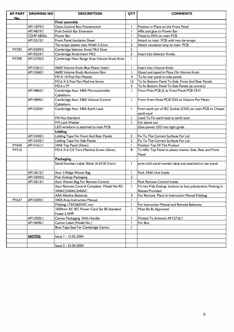
Final assembly
AP11879/3 Opus Control Box Powerswitch 1 Position in Place on the Front Panel
AP14819/1 Push Switch Bar Extension 1 Affix and glue to Power Bar
CD4P AB05a Power Bar 1 Fitted to SW3 on main PCB
AP15512/1 Front Panel Insulation Sheet 1 Attach to main PCB with two tie-wraps
Tie-wraps (plastic ties) Width 2.5mm 2 Attach insulation strip to main PCB
PY592 AP10209/3 Cambridge Selector Knob Mk3 Silver 3
AP10224/1 Cambridge Knob Insert Mk2 3 Insert Into Selector Knobs
PY590 AP12750/2 Cambridge New Range Amp Volume Knob Silver 1
AP13361/1 A600 Volume Knob Blue Plastic Insert 1 Insert Into Volume Knob
AP13360/1 A600 Volume Knob Aluminium Skin 1 Glued and taped In Place On Volume Knob
M3 X 10 Pozi Pan Plastite 4 To fix rear panel to side panels
M2.6 X 6 Pozi Pan Machine Screw 12 To fix Bottom Panel To Side, Front And Rear Panels
M2.6 x ??? 4 To fix Bottom Panel To Side Panels (at corners)
AP14865/1 Cambridge Azur 340A Microcontroller
Cableform
1 From Main PCB J2 to Front Panel PCB CN2
AP14896/1 Cambridge Azur 340A Volume Control
Cableform
1 From Front Panel PCB CN5 to Volume Pot Motor
AP15204/1 Cambridge Azur 340A Earth Lead 1 From earth pin of IEC Scoket (CN3) on main PCB to Chassis
earth stud
M4 Nut Standard 1 Used To Fix earth lead to earth stud
M4 Lock Washer 1 For above nut
LED wireform is attached to main PCB Glue power LED into light-guide
Lidding
AP13340/1 Lidding Tape For Front And Rear Panels 2 Fix To The Correct Surfaces For Lid
AP13342/1 Lidding Tape For Side Panels 2 Fix To The Correct Surfaces For Lid
PY640 AP14161/1 340A Top Panel (Silver) 1 Position Top Of The Product
PY516 M2.6 X 6 C/S Torx Machine Screw (Silver) 8 To Affix Top Panel to plastic Inserts, Side, Rear and Front
Panel
Packaging
Serial Number Label, Blank (6.5X35.5mm) 1 print with serial number label and attached to rear panel
AP13612/1 Azur 2 Ridge Woven Bag 1 Pack 340A Unit Inside AP13504/2 Poly Endcap Packaging 2
AP13613/1 Azur Woven Bag For Remote Control 1 Pack Remote Control Inside,
Azur Remote Control Complete. Model No RC-
340AC/540AC/640AC
1 Fit into Poly Endcap, buttons to face polystyrene, Packing in
Rebate Provided
AAA Alkaline Batteries 3 For Remote. Place In Instruction Manual Polybag
PY637 AP15509/1 340A Amp Instruction Manual 1
Polybag 173X260X4C mm 1 For Instruction Manual and Remote Batteries
1830mm AC IEC Power Cord Set BS Standard
Fused 3 AMP
1 Must Be Bs Approved
AP13505/1 Carton Packaging With Handle 1 Printed To Artwork AP13716/1
AP14696/1 Carton Label (Model No.) 1 For Box
Blue Tape Seal For Cambridge Carton 1
NOTES: Issue 1 - 15.03.2004
Issue 2 - 23.04.2004
5
7/23/2019 Cambridge Azur 340A Int Sm
http://slidepdf.com/reader/full/cambridge-azur-340a-int-sm 6/21
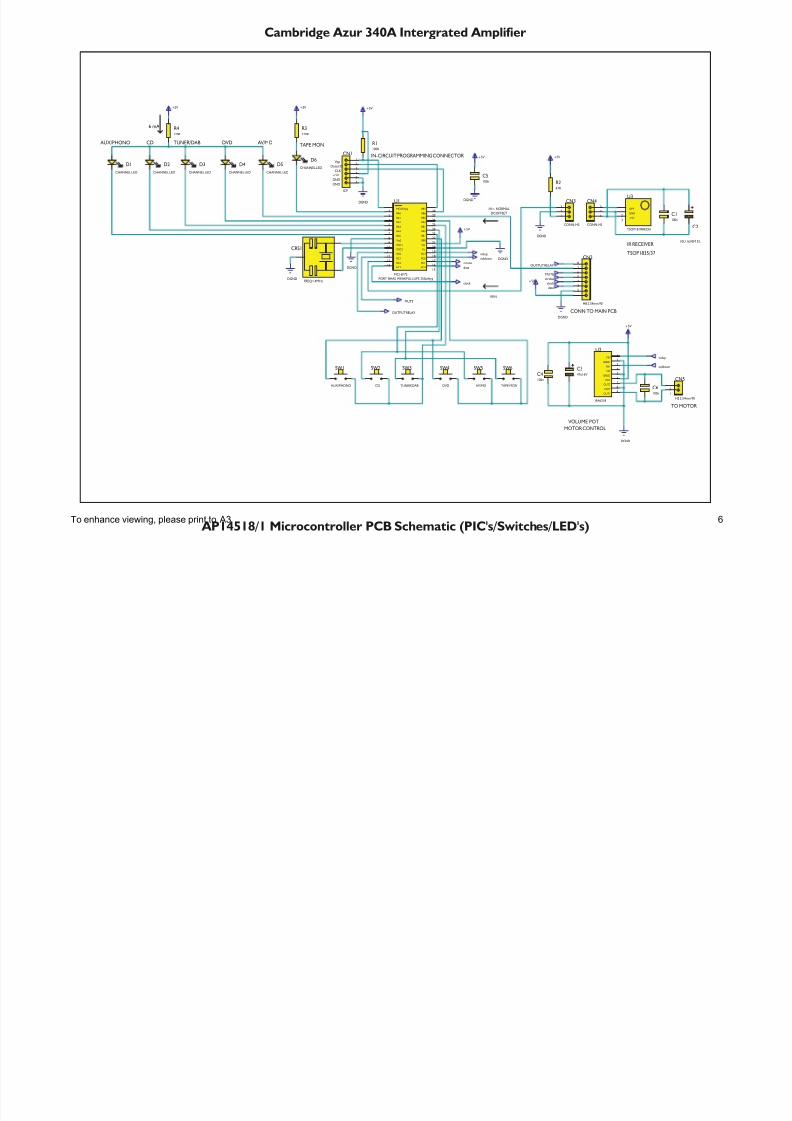
Cambridge Azur 340A Intergrated Amplifier
AP14518/1 Microcontroller PCB Schematic (PIC's/Switches/LED's)
RC617
RC516
RC415
RC314
RC213
RC112
RC011
OSC210
RA02
RA24
MCLR/Vpp1
RA13
RA35
RB122
RB728
RA46
RA57
Vss28
OSC19
RB223
RB324
RB627
RB425
RB526
Vss19
RC718
Vdd20
RB021
U1
PIC16F72
CRS1
FREQ=4MHz
1
2
CN5
H2 2.54mm 90
C6100n
FIN1
GND12
RIN3
NC4
GND25
VCC6
OUT27
COM8
OUT1 9
U2
BA6218
+5V
DGND
DGND
DGND
+5V
DGND
C5100n
R4220R
+5V
D1
CHANNEL LED
D2
CHANNEL LED
D3
CHANNEL LED
D4
CHANNEL LED
D5
CHANNEL LED
D6
CHANNEL LED
SW2
CD
SW3
TUNER/DAB
SW5
AV/MD
SW1
AUX/PHONO
SW6
TAPE MON
SW4
DVD
+5V 3
OPT1
GND2
U3
TSOP18 IRRECEI
C1100n
strobe
data
clock clock
data
strobe
volup
voldown
volup
voldown
C347u16V
R3220R
C4100n
1
2
3
4
5
6
7
8
CN2
H8 2.54mm 90
DGND
+5V
IR RECEIVER
AUX/PHONO CD TUNER/DAB TAPE MONDVD AV/MD
1
2
3
CN3
CONN-H3
1
2
3
CN4
CONN-H3
MOTOR CONTROL
CONN TO MAIN PCB
MUTE
+5V
DGND
PORT BHAS WEAKPULLUPS 250uAtyp
IN-CIRCUIT PROGRAMMING CONNECTOR
R1100K
+5V
DGND
+5V
GND
Vpp
CLK
1
2
3
4
5
6
CN1
ICP
GND
DataI/O
DGND
MUTE
TO MOTOR
VOLUME POT
+5V +5V
OUTPUT RELAY
IRIN
DCOFFSET
OUTPUT RELAY
R247R
HI= NORMAL
C2
10U 16VSM EL
TSOP1835/37
6 mA
To enhance viewing, please print to A3 6
7/23/2019 Cambridge Azur 340A Int Sm
http://slidepdf.com/reader/full/cambridge-azur-340a-int-sm 7/21
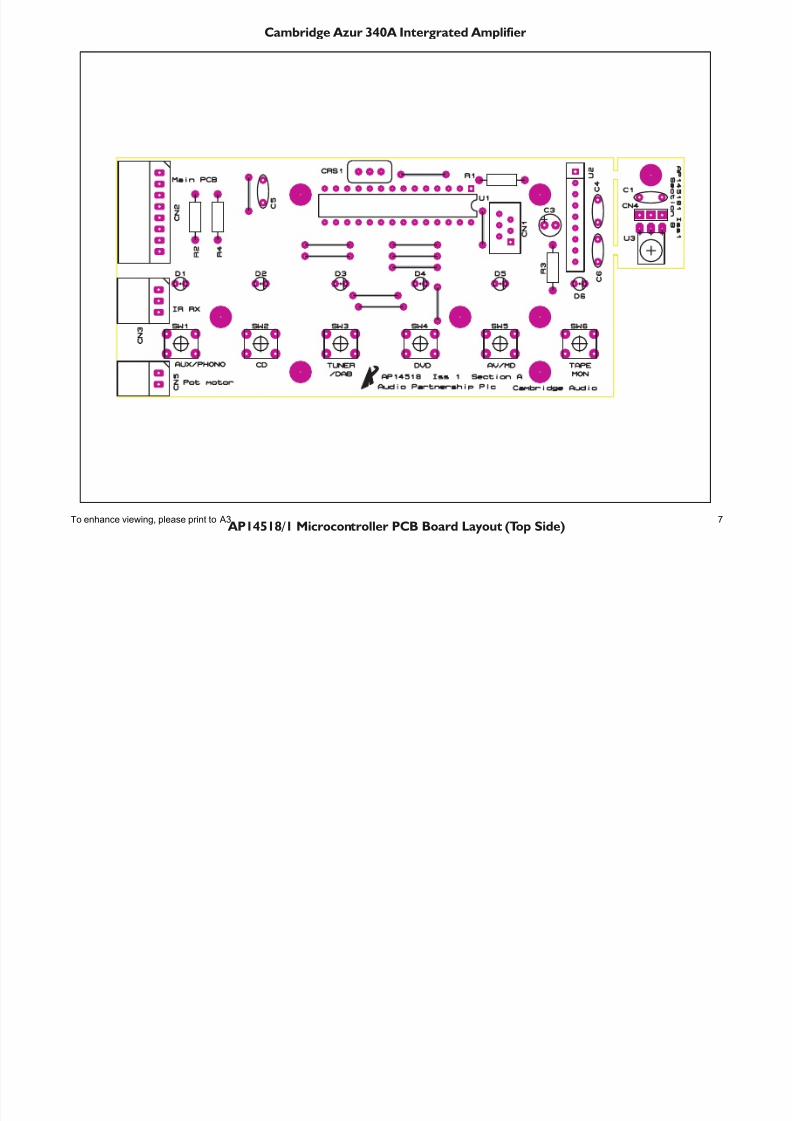
Cambridge Azur 340A Intergrated Amplifier
AP14518/1 Microcontroller PCB Board Layout (Top Side)To enhance viewing, please print to A3 7
7/23/2019 Cambridge Azur 340A Int Sm
http://slidepdf.com/reader/full/cambridge-azur-340a-int-sm 8/21
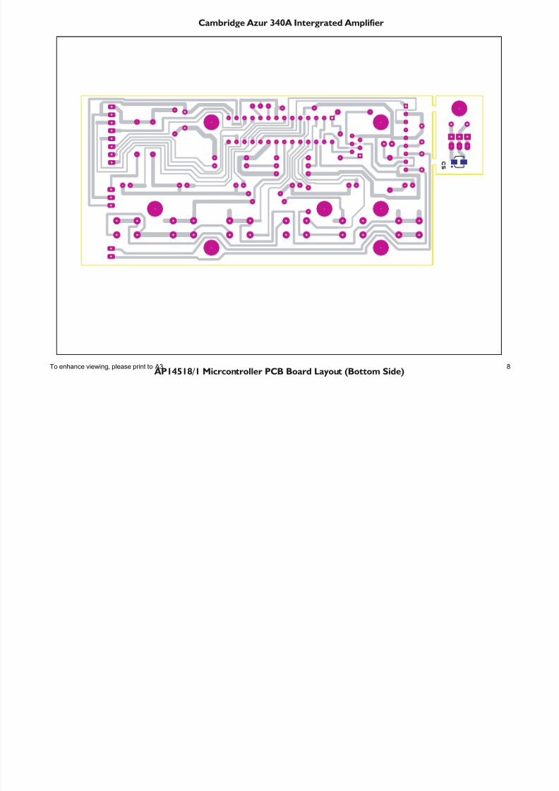
Cambridge Azur 340A Intergrated Amplifier
AP14518/1 Micrcontroller PCB Board Layout (Bottom Side)To enhance viewing, please print to A3 8
7/23/2019 Cambridge Azur 340A Int Sm
http://slidepdf.com/reader/full/cambridge-azur-340a-int-sm 9/21
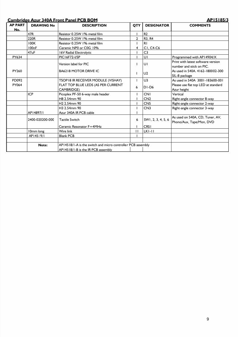
AP15185/3 AP PART
No.
DRAWING No DESCRIPTION QTY DESIGNATOR COMMENTS
47R Resistor 0.25W 1% metal film 1 R2
220R Resistor 0.25W 1% metal film 2 R3, R4
100K Resistor 0.25W 1% metal film 1 R1
100nF Ceramic NP0 or C0G 10% 4 C1, C4-C6
47uF 16V Radial Electrolytic 1 C3
PY634 PIC16F72-I/SP 1 U1 Programmed with AP14904/X Version label for PIC 1 U1
Print with latest software version
number and stick on PIC.
PY260 BA6218 MOTOR DRIVE IC1 U2
As used in 540A. 4162-180002-300
SIL-8 package
PD092 TSOP18 IR RECEIVER MODULE (VISHAY) 1 U3 As used in 540A 3001-183600-001
PY064 FLAT TOP BLUE LEDS (AS PER CURRENT
CAMBRIDGE)6 D1-D6
Please use flat top LED at standard
Azur height
ICP Picoplex PF-50 6-way male header 1 CN1 Vertical
H8 2.54mm 90 1 CN2 Right-angle connector 8-way
H2 2.54mm 90 1 CN5 Right-angle connector 2-way
H3 2.54mm 90 1 CN3 Right-angle connector 3-way
AP14897/1 Azur 340A IR PCB cable 1
2400-020200-000 Tactile Switch 6 SW1, 2, 3, 4, 5, 6 As used on 540A, CD, Tuner, AV,Phono/Aux, Tape/Mon, DVD
Ceramic Resonator F=4MHz 1 CRS1
10mm long Wire link 11 LK1-11
AP14519/1 Blank PCB 1
Note:
AP14518/1-B is the IR PCB assembly
Cambridge Azur 340A Front Panel PCB BOM
AP14518/1-A is the switch and micro controller PCB assembly
9
7/23/2019 Cambridge Azur 340A Int Sm
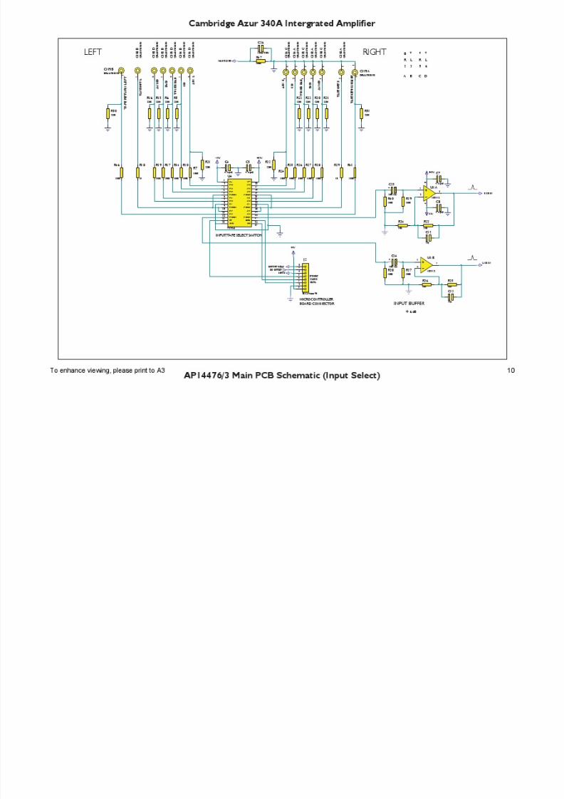
http://slidepdf.com/reader/full/cambridge-azur-340a-int-sm 10/21
7/23/2019 Cambridge Azur 340A Int Sm
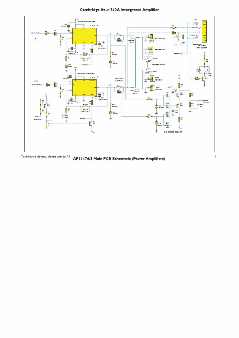
http://slidepdf.com/reader/full/cambridge-azur-340a-int-sm 11/21
7/23/2019 Cambridge Azur 340A Int Sm
http://slidepdf.com/reader/full/cambridge-azur-340a-int-sm 12/21
7/23/2019 Cambridge Azur 340A Int Sm
http://slidepdf.com/reader/full/cambridge-azur-340a-int-sm 13/21
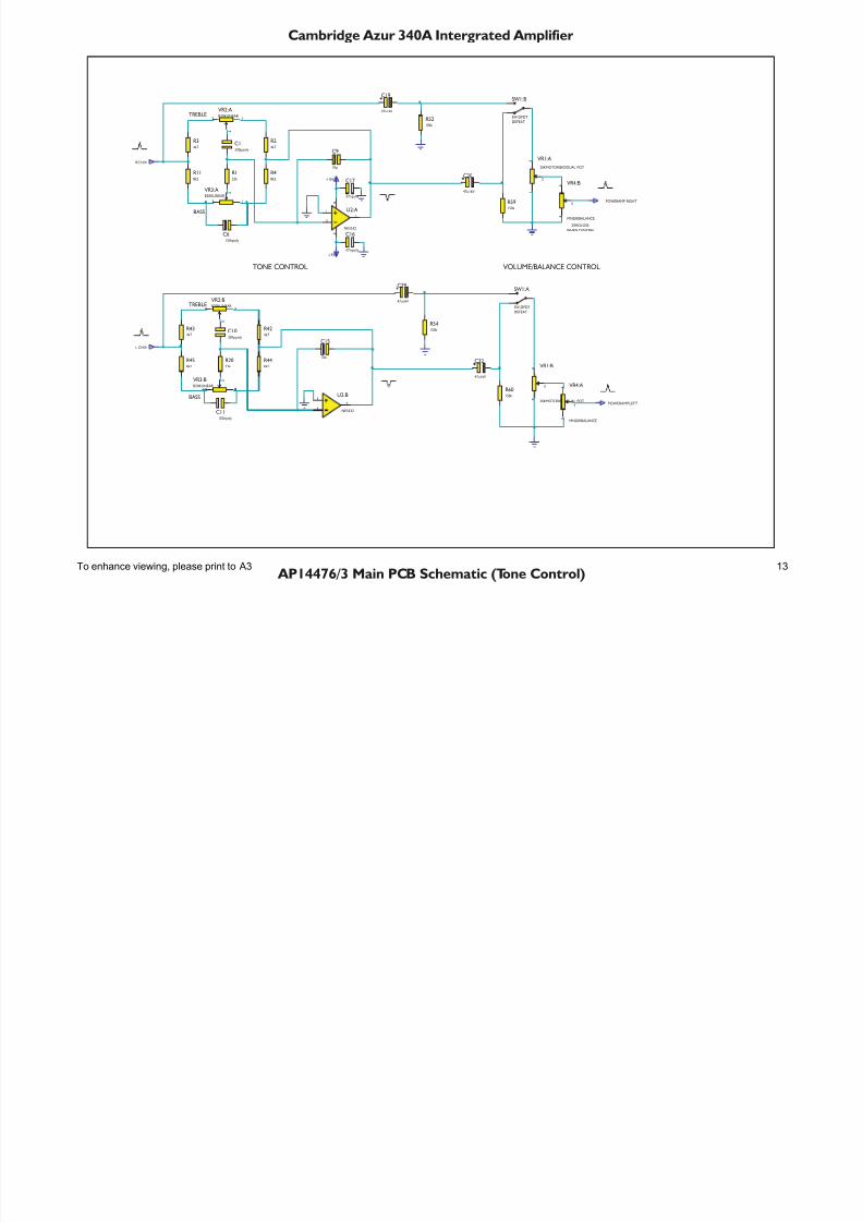
Cambridge Azur 340A Intergrated Amplifier
AP14476/3 Main PCB Schematic (Tone Control)
C1330p poly
R122k
R24k7
R34k7
R48k2
R118k2
C6150npoly
C9
10p
SW1:A
SW-DPDT
DEFEAT
-15V
+15V
C10330p poly
R2022k
R424k7
R434k7
R448k2
R458k2
C11150npoly
C15
10p
SW1:B
SW-DPDT
DEFEAT
C16
47npoly
C17
47npoly
3
2
1
8
4
U2:A
NE5532
5
6
7
U2:B
NE5532
RCHIN
L CHIN
POWERAMP RIGHT
POWERAMPLEFT
R52150k
R54150k
R59150k
R60150k
1
3
2
VR1:A
20KMOTORISEDDUAL POT
4
6
5
VR1:B
20KMOTORISEDDUAL POT
4
6
5
VR4:B
MN20KBALANCE
1
3
2
VR4:A
MN20KBALANCE
13
2
VR2:A B20KLINEAR
46
5
VR2:BB20KLINEAR
13
2 VR3:A B20KLINEAR
46
5 VR3:BB20KLINEAR
ZEROLOSS
WHEN CENTRAL
TONE CONTROL VOLUME/BALANCE CONTROL
TREBLE
BASS
TREBLE
BASS
C19
47u16V
C20
47u16V
C29
47u16V
C32
47u16V
To enhance viewing, please print to A3 13
7/23/2019 Cambridge Azur 340A Int Sm
http://slidepdf.com/reader/full/cambridge-azur-340a-int-sm 14/21
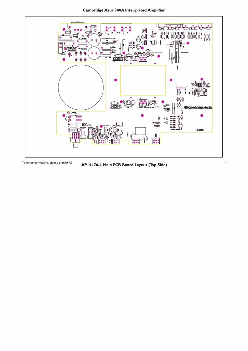
Cambridge Azur 340A Intergrated Amplifier
AP14476/4 Main PCB Board Layout (Top Side)To enhance viewing, please print to A3 14
7/23/2019 Cambridge Azur 340A Int Sm
http://slidepdf.com/reader/full/cambridge-azur-340a-int-sm 15/21
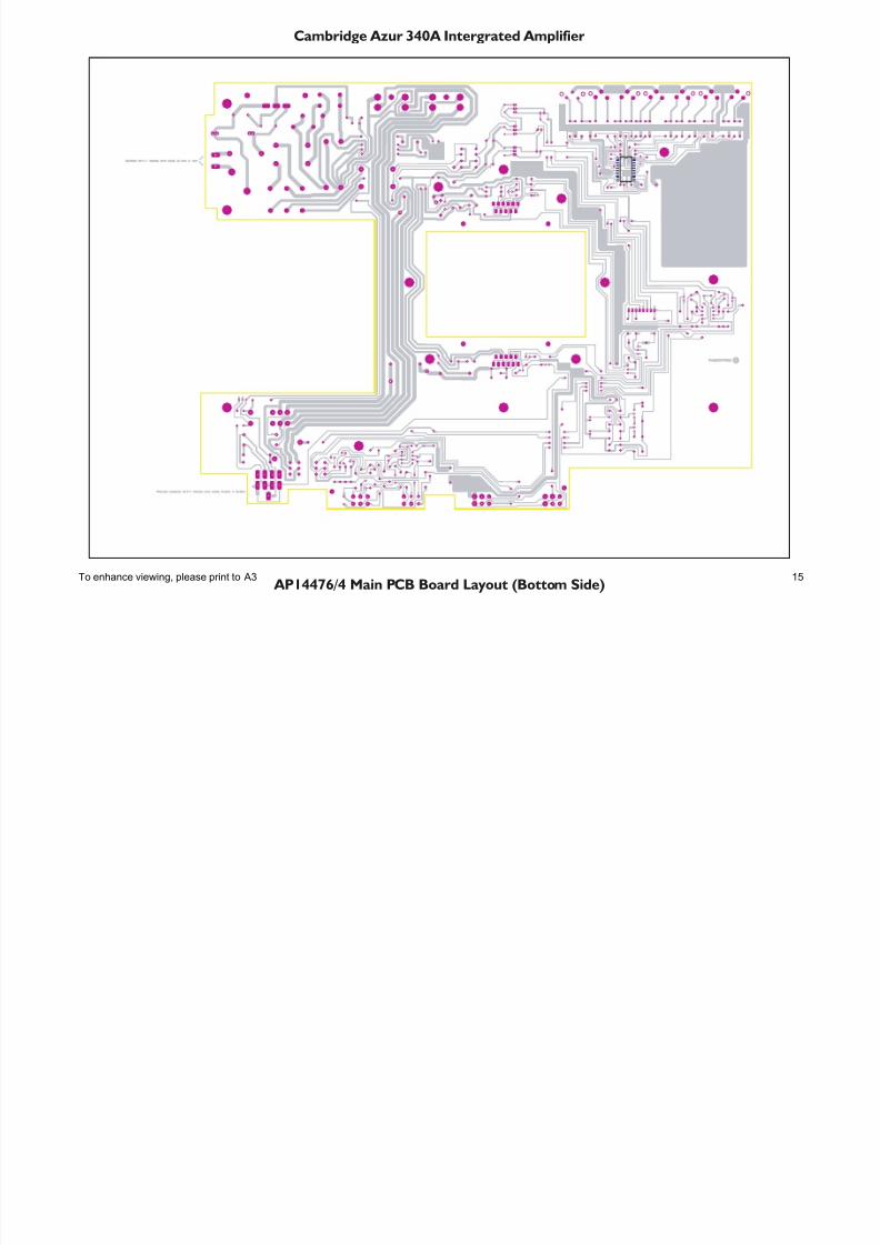
Cambridge Azur 340A Intergrated Amplifier
AP14476/4 Main PCB Board Layout (Bottom Side)To enhance viewing, please print to A3 15
7/23/2019 Cambridge Azur 340A Int Sm
http://slidepdf.com/reader/full/cambridge-azur-340a-int-sm 16/21
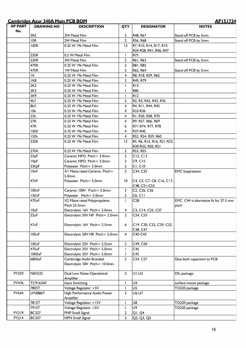
AP151734 AP PART
No.
DRAWING NO DESCRIPTION QTY DESIGNATOR NOTES
2R2 2W Metal Film 2 R48, R67 Stand off PCB by 5mm
10R 2W Metal Film 2 R56, R68 Stand off PCB by 5mm
100R 0.25 W 1% Metal Film 13 R7, R10, R14, R17, R19,
R24-R28, R41, R46, R47
220R 0.5 W Metal Film 1 R75
220R 3W Metal Film 2 R61, R63 Stand off PCB by 5mm470R 0.25 W 1% Metal Film 2 R81, R82
470R 1W Metal Film 2 R62, R64 Stand off PCB by 5mm
1K 0.25 W 1% Metal Film 4 R8, R18, R29, R65
1K8 0.25 W 1% Metal Film 2 R49, R79
2K2 0.25 W 1% Metal Film 1 R13
3K3 0.25 W 1% Metal Film 1 R80
3K9 0.25 W 1% Metal Film 1 R12
4k7 0.25 W 1% Metal Film 5 R2, R3, R42, R43, R76
8k2 0.25 W 1% Metal Film 4 R4, R11, R44, R45
10k 0.25 W 1% Metal Film 4 R33-R36
22k 0.25 W 1% Metal Film 4 R1, R20, R58, R70
27K 0.25 W 1% Metal Film 4 R9, R57, R66, R6947K 0.25 W 1% Metal Film 6 R71-R74, R77, R78
100K 0.25 W 1% Metal Film 4 R37-R40
150k 0.25 W 1% Metal Film 4 R52, R54, R59, R60
220K 0.25 W 1% Metal Film 12 R5, R6, R15, R16, R21-R23,
R30-R32, R50, R51
270K 0.25 W 1% Metal Film 2 R53, R55
22pF Ceramic NPO. Pitch= 3.0mm 2 C12, C13
10pF Ceramic NPO. Pitch= 3.0mm 2 C9, C15
330pF Polyester. Pitch= 5.0mm 2 C1, C10
10nF X1 Mains rated Ceramic. Pitch=
5.0mm
2 C34, C35 EMC Suppression
47nF Polyester Pitch= 5.0mm 10 C4, C5, C7, C8, C16, C17,
C48, C51-C53
100nF Ceramic 100V Pitch= 5.0mm 3 C2, C26, C36
150nF Polyester Pitch= 5.0mm 2 C6, C11
470nF X2 Mains rated Polypropylene.
Pitch 22.5mm
1 C28 EMC. C44 is alternative fit for 27.5 mm
pitch
10uF Electrolytic 16V Pitch= 2.0mm 4 C3, C14, C25, C37
22uF Electrolytic 50V NP Pitch= 2.0mm 2 C54, C55
47uF Electrolytic 16V Pitch= 2.5mm 6 C19, C20, C22, C29, C32,
C38, C47
100uF Electrolytic 50V HR Pitch= 5.0mm 4 C40-C43
100uF Electrolytic 25V Pitch= 2.5mm 2 C49, C50470uF Electrolytic 35V Pitch= 5.0mm 1 C46
1000uF Electrolytic 35V Pitch= 5.0mm 1 C45
6800uF Cambridge Audio Branded
Electrolytic 50V Pitch= 10.0mm
2 C24, C27 Glue both capacitors to PCB
PY259 NE5532 Dual Low Noise Operational
Amplifier
2 U1,U2 DIL package
PY476 TC9163AF Input Switching 1 U4 surface mount package
7805T Voltage Regulator +5V 1 U5 TO220 package
PY644 LM3886T High Performance Audio Power
Amplifier
2 U6,U7
7815T Voltage Regulator +15V 1 U8 TO220 package
7915T Voltage Regulator -15V 1 U9 TO220 package
PY219 BC327 PNP Small Signal 2 Q1, Q4
PY214 BC337 NPN Small Signal 3 Q2, Q3, Q5
Cambridge Azur 340A Main PCB BOM
16
7/23/2019 Cambridge Azur 340A Int Sm
http://slidepdf.com/reader/full/cambridge-azur-340a-int-sm 17/21
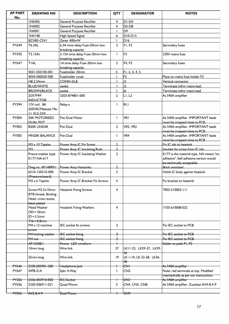
AP PART
No.
DRAWING NO DESCRIPTION QTY DESIGNATOR NOTES
1N5402 General Purpose Rectifier 4 D1-D4
1N4002 General Purpose Rectifier 4 D5-D8
1N4001 General Purpose Rectifier 1 D9
1N4148 High Speed Signal 6 D10-D15
BZX85-C5V1 Zener 400mW 1 D16
PY649 T6.3AL 6.3A time delay Fuse-20mm low
breaking capacity
2 F1, F2 Secondary fuses
PY595 T3.15AL 3.15A time delay Fuse-20mm low
breaking capacity
1 F3 230V mains fuse
PY647 T1AL 1A time delay Fuse-20mm low
breaking capacity
2 F4, F5 Secondary fuses
4031-050100-001 Fuseholder 20mm 5 F1, 2, 3, 4, 5
4034-000030-000 Fuseholder cover 1 F3 Place on mains fuse holder F3
H8 2.54mm CONN-SIL8 1 J2 Vertical connector
BLUE/WHITE eyelet 1 J5 Terminate txfmr mains lead
BROWN/BLACK eyelet 1 J6 Terminate txfmr mains lead
25X7MM
INDUCTOR
3203-874801-000 2 L1, L2 As 540A amplifier
PY594 12V coil, 8A
250VACMassuse Me-
11 012-2Z4
Relay-s 1 RL1
PY004 20K MOTORISED
DUAL POT
Pot-Dual-Motor 1 VR1 As 540A amplifier. IMPORTANT leads
must be cropped close to PCB
PY003 B20K LINEAR Pot-Dual 2 VR2, VR3 As 540A amplifier. IMPORTANT leads
must be cropped close to PCB
PY005 MN20K BALANCE Pot-Dual 1 VR4 As 540A amplifier. IMPORTANT leads
must be cropped close to PCB
M3 x 10 Taptite Power Amp IC Fix Screw 2 Fix IC tab to heatsink
M3 Power Amp IC Insulating Bush 2 Insulate fix screw from IC tab
Precut washer type
K177-NA-617
Power Amp IC Insulating Washer 2 K177 is the material type. NA means "no
adhesive". Self-adhesive version would
be technically acceptable.
Dwg no: AP14899/1 Power Amp Heatsinks 2 Black anodised
6510-150310-000
(Pressure board)
Power Amp IC Bracket 2 Holds IC body against heatsink
M3 x 6 Taptite Power Amp IC Bracket Fix Screws 4 Fix bracket to heatsink
Screw M3.5x10mm
BTB thread, Binding
Head, cross recess,
black plated
Heatsink Fixing Screws 4 7003-510003-111
Metal Washer
OD=10mm
ID=3.5mm
Thk=0.8mm
Heatsink Fixing Washers 4 7103-610008-022
M4 x 12 machinescrew IEC socket fix screws 2 Fix IEC socket to PCB
M4 locking washer IEC socket fixing 2 Fix IEC socket to PCB
M4 nut IEC socket fixing 2 Fix IEC socket to PCB
AP15508/1 Power LED wireform 1 Solder to pads P1, P2
10mm long Wire link 37 LK11-22, LK29-37, LK39-
56
25mm long Wire link 19 LK 1-10, LK 23-28, LK36-
38
PY646 2330-005901-300 Headphone Jack 1 CN1 As 540A amplifier
PY647 WP8-21A Spkr 4-Way 1 CN2 Note: red terminals at top. Modified
mechanically as per our instructions.
PY226 2336-003910-002 IEC-Socket 1 CN3 As 540A amplifier
PY036 2330-006911-021 Quad Phono 3 CN4, CN5, CN8 As 540A amplifier, Zuanbao AV4-8.4-9
PY035 AV2-8.4-9 Dual Phono 1 CN9
17
7/23/2019 Cambridge Azur 340A Int Sm
http://slidepdf.com/reader/full/cambridge-azur-340a-int-sm 18/21
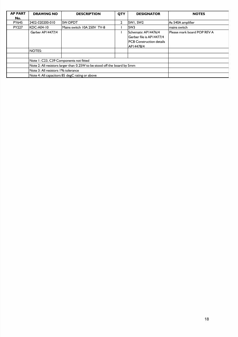
AP PART
No.
DRAWING NO DESCRIPTION QTY DESIGNATOR NOTES
PY645 2402-020200-010 SW-DPDT 2 SW1, SW2 As 540A amplifier
PY227 KDC-A04-10 Mains switch 10A 250V TV-8 1 SW3 mains switch
Gerber AP14477/4 1 Schematic AP14476/4
Gerber file is AP14477/4
PCB Construction details
AP14478/4
Please mark board POP REV A
NOTES:
Note 4: All capacitors 85 degC rating or above
Note 1: C23, C39 Components not fitted
Note 2: All resistors larger than 0.25W to be stood off the board by 5mm
Note 3: All resistors 1% tolerance
18
7/23/2019 Cambridge Azur 340A Int Sm
http://slidepdf.com/reader/full/cambridge-azur-340a-int-sm 19/21
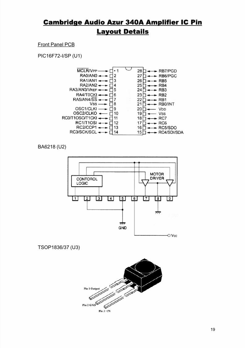
Cambridge Audio Azur 34 A Amplifier IC Pin
Layout Details
Front Panel PCB
PIC16F72-I/SP (U1)
BA6218 (U2)
TSOP1836/37 (U3)
19
7/23/2019 Cambridge Azur 340A Int Sm
http://slidepdf.com/reader/full/cambridge-azur-340a-int-sm 20/21
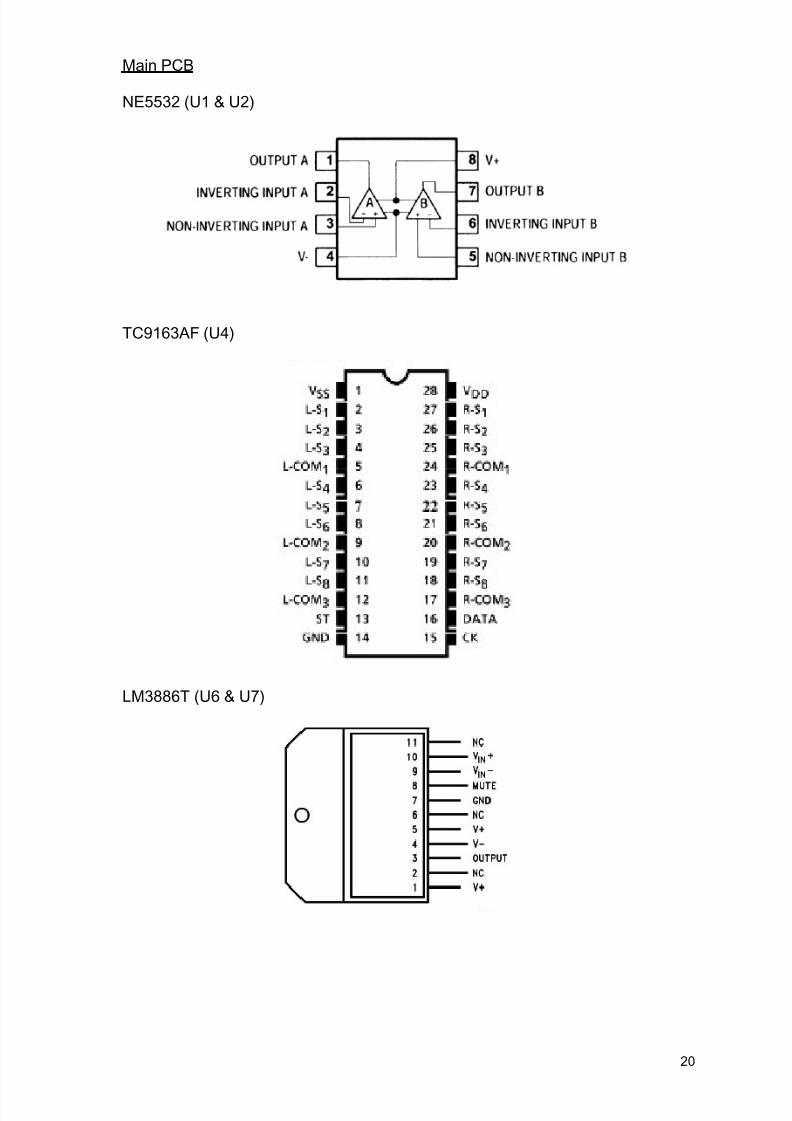
Main PCB
NE5532 (U1 & U2)
TC9163AF (U4)
LM3886T (U6 & U7)
20

7/23/2019 Cambridge Azur 340A Int Sm
http://slidepdf.com/reader/full/cambridge-azur-340a-int-sm 21/21
AP158421
AP PART
No.
DRAWING
NODESCRIPTION QTY COMMENTS
CARTON LABEL (MODEL NO.) UK BLACK 1 FOR BOX
PY593 CAMBRIDGE SELECTOR KNOB MK3 Black 3
PY591 CAMBRIDGE NEW RANGE AMP VOLUME KNOB Black 1
PY639
CAMBRIDGE FRONT PANEL (PUNCHED AND PRINTED)
Black 1 SCREENED WITH ARTWORK AP13679/2
CAMBRIDGE NEW RANGE AMP 7mm TAC SWITCH BUTTON 6 POSITION IN PLACE ON THE FRONT PANEL
CAMBRIDGE NEW RANGE AMP 7mm PUSH SWITCH
BUTTON 2 POSITION IN PLACE ON THE FRONT PANEL
PY531 CAMBRIDGE NEW RANGE FOOT MOULDING 4 POSITION IN PLACE ON BOTTOM PANEL
PY641 340A Top Panel (Black) 1 POSITION ON TOP OF THE PRODUCT
PY515 M2.6 x 8 MC Torx Recessed Black 8 TOP PANEL SCREWS
Cambridge Azur 340A Silver - Black Diffrences BOM