
Cambium Networks LTE Programd24wuq6o951i2g.cloudfront.net/img/events/2981539/... · LTE Solutions...
16
Cambium Networks LTE Program EMEA Partner Event – Budapest, July 2018
Transcript of Cambium Networks LTE Programd24wuq6o951i2g.cloudfront.net/img/events/2981539/... · LTE Solutions...

Cambium Networks LTE Program
EMEA Partner Event – Budapest, July 2018
2
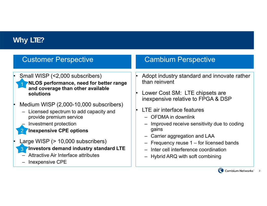
Why LTE?
Customer Perspective Cambium Perspective
• Small WISP (<2,000 subscribers)– NLOS performance, need for better range
and coverage than other available solutions
• Medium WISP (2,000-10,000 subscribers)– Licensed spectrum to add capacity and
provide premium service– Investment protection– Inexpensive CPE options
• Large WISP (> 10,000 subscribers)– Investors demand industry standard LTE– Attractive Air Interface attributes– Inexpensive CPE
• Adopt industry standard and innovate rather than reinvent
• Lower Cost SM: LTE chipsets are inexpensive relative to FPGA & DSP
• LTE air interface features– OFDMA in downlink– Improved receive sensitivity due to coding
gains– Carrier aggregation and LAA– Frequency reuse 1 – for licensed bands– Inter cell interference coordination– Hybrid ARQ with soft combining
1
2
3
3
Why Not Use Existing LTE solutions?
– Too complex (EPC, SIM cards)
– Too costly
– Not Fixed Service Provider-friendly
– Products that exist are immature or “beta quality”

4
Cambium Networks - Differentiating on a Standard
• Remove cost and complexity typically associated with LTE
• Exploit LTE Air Interface Features
• High power radio to take advantage of higher regulatory limits in 2.5GHz and 3.5 GHz
• Leverage our expertise in robust outdoor CPE design
• Retain PMP 450 networking, QoS, security and management features


6
Our LTE Solution
ExistingLTE
Solutions
Cambium PMP
Cambium LTE
Customer Experience N/A
Range and Coverage
Interference Mitigation
Total Sector Capacity
Subscriber Bandwidth
Infrastructure Costs
Mobility Support
Total Cost of Ownership
WorstBest
• Building on our 450 to LTE comparison, we close the gap between the existing solutions and the Cambium LTE solution.
• 450 still outperforms LTE in many ways, but Cambium’s LTE addresses deficiencies in alternative LTE solutions.
7
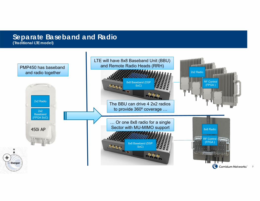
Separate Baseband and Radio(Traditional LTE model)
2x2 Baseband
(FPGA SoC)
2x2 Radio
450i AP
8x8 Baseband (DSP SoC)
RF Control (FPGA )
2x2 Radio
RF Control (FPGA )
8x8 Radio
PMP450 has baseband and radio together
LTE will have 8x8 Baseband Unit (BBU) and Remote Radio Heads (RRH)
The BBU can drive 4 2x2 radios to provide 360⁰ coverage …
… Or one 8x8 radio for a singleSector with MU-MIMO support
8x8 Baseband (DSP SoC)

8
Deployment
DC
In
CPRI (Fiber)
• Start with one RRH, add more as you grow, all powered by same BBU
• RRH band spins without changing BBU hardware
• Future proof for LAA, just add 5GHz RRU to existing BBU
• No tower climb needed to access BBU –easier diagnostics, lower operational expense
BBU
Sync In
ISP Data Network

9
Flexibility by splitting Baseband and Radio
• Start with one RRH, add more as you grow, all powered by same BBU
• Future proof for LAA, just add 5GHz RRU to existing BBU
• RRH bandspins without changing BBU hardware
2.5GHz 3.5GHz 5 GHz
• No tower climb needed to access BBU –easier diagnostics, lower operational expense
2.5GHz 5 GHz

10
Planned Spectrum Coverage
Band 42 (TDD) Band 43 (TDD)
Band 48 (TDD)
First Release, Q4, 2018 2nd Release, Q2, 20193.4 GHz 3.6 GHz 3.8 GHz
3.55 GHz 3.7 GHz
Band 40 (TDD) Band 41 (TDD)
Band 38 (TDD)
2300 MHz 2400 MHz 2690 MHz
2570 MHz 2620 MHz
2496 MHz

11
Private LTE Solutions at 2300 MHz (Band 40)

12
Uncovering Opportunity
Potential Band 40 opportunity for Electricity Distributors in Slovenia
Likely that other similar opportunities can be found throughout Europe

13
Baseba
nd Unit
Remote Ra
dio He
ad
Band 38, 40, 41 2.3 GHz to 2.7 GHz
2TX, 2RX 2W per port CPRI (fiber) connection to
BBU 90° sector antenna 17 dBi antenna gain IP66/IP67
Future Enhancements CA (20+20, 10+10) Dual sector (no CA) Available 8W per port
version Subscriber M
odule
What is being delivered? Q4 2018
Band 38, 40, 41 2.3 GHz to 2.7 GHz
CAT 4 1 TX, 2 RX 100/50 Mbps 1x GigE port 30V DC Input 14 dBi integrated patch
Future Enhancements CAT 6 High Gain Integrated
Dish Dual‐Band (2 + 3 GHz)
LTE‐A Rel 12 19” rack mount unit 8TX, 8RX Drive 3 120° sectors (2x2
each) over CPRI 64 SM per sector GPS in 2x GigE ports Integrated EPC
Future Enhancements Dual sector, LAA Carrier aggregation 600/100 Mbps 1588v2 1024 SM support
• No mobility• No roaming

14
Network Component Q4 2018 Q1 2019 Q2 2019 2H, 2019 2020
3 GHz 450m – 8x8 MU-MIMO 3 GHz 450b High Gain
OFDM-A Enhanced FEC
Carrier Aggregation MU-MIMOLAA – LTENarrowband IOT
8Tx, 8Rx(High Performance)
1024 SMs 2Tx, 2RxIntegrated Radio(Lower Cost)
2.3 – 2.7 GHz (Bands 38, 40, 41)2x2 – 2W per port
2.3 – 2.7 GHz (Bands 38, 40, 41)2x2 – 8W per port (possibly 10W per port)
3.4 – 3.8 GHz(Bands 42, 43, 48)2x2 (450 SM support)
5.1 – 5.9 GHz (2x2)
3.4 – 3.8 GHz – 8x8(MU-MIMO)
2.3 – 2.7 GHz – 8x8(MU-MIMO)
2.3 – 2.7 GHz (14 dBi Int.)CAT 4 SM
2.3 – 2.7 GHz (High Gain) CAT 6 SM
3.4 – 3.8 GHz(Mid and High Gain)CAT 4,6 SM
3.5 + 5 GHz CA(High Gain)CAT 6 SM
CAT 12 SM
LTE Roadmap
BBU
450 Platform
SM
Product concepts described in this presentation may still be under investigation or development. Specific details, specifications and timelines are subject to change without notice. Cambium makes no commitment or representation that such product concepts will be available as commercial products.
RRH

15
Nov Dec Jan Feb Mar Apr May Jun Q3 Q4 1H 2H
Cambium cnRanger Roadmap
2019 2020
R1.0 – Nov• Sierra 800 BBU• 2 GHz Palisade 200 (2x2 RRH)• 2 GHz Tyndall 100 (Cat 4 SM)• Initial Release
Completed Gate 2Committed Gate 7In Planning Gate 10Evaluating Gate 13Candidate Gate 15
PLAN OF INTENTSUBJECT TO CHANGE
June, 2018
R1.1 – Q1• 2 GHz Tyndall 210 (Cat 6 SM)• 2 GHz Palisade 210 (2x2 RRH, High Power)
R1.2• 3 GHz Palisade 200 (2x2 RRH)• 3 GHz Tyndall 100 (Cat 4 SM)• 3 GHz Tyndall 210 (Cat 6 SM)
• 2 Carrier Aggregation• 1024 SM Support in BBU
R1.3 – Q4, 2019• Tyndall 220 (Cat 6 Dual Band SM)
• 4 Carrier Aggregation
2018
R2 – 2020• 3 GHz Palisade 800 (8x8 RRH)• Tyndall 300 (Cat 12 Dual Band SM)
• MU‐MIMO• LAA• Narrow Band IOT


