Cam Mechanism Kinematic Analysis Used in a Human … · Cam Mechanism Kinematic Analysis Used in a...
5
Abstract—In this paper we follow to elaborate a new prosthetic mechanical system which will substitute the human ankle joint. The new prosthetic mechanical system design, will be accomplished by performing a kinematic analysis on analytical way. The designed prosthetic mechanical system will be experimentally tested on a human subject with locomotion disabilities. Index Terms— modeling, kinematics, shank prosthesis. I. INTRODUCTION In the case of shank prosthesis, this are fabricated from materials which posses a capacity to memorize shapes and to store energy developed in different activities. The mobility from the ankle joint level is generated by the deformation of the foot replacement component in elastic field [9], [10], [13]. With this it can be kept the angular amplitude, in order to realize the dorsal or plantar flexion. In figure 1 a, b, we present a Venture shank prosthesis used in ankle disarticulations, fabricated by the College Park Industries [8]. The prosthesis components are: shank flare (1); catching device (2); superior component (3); dumper components (4, 5); inferior component (6); fixation elements (7); artificial foot (8). In figure 2 we present a Elite Foot shank prosthesis, fabricated by Blatchford and Sons Ltd England [12]. This type of prosthesis posses the following characteristics: no mechanical systems; permits the ankle valgus or varus motion, due to specific form of the prosthetic foot; special design in order to take over the reaction forces from the ground contact in the concentrated points. This is an advantage because the components are individually stressed, and are fabricated from carbon fibber which posses the shape memory capacity. The prosthetic mechanical system’s imposed conditions are: to realize the motion with an angular amplitude almost identical with the one developed by a healthy human subject (55 degrees); to permit dorsal/plantar flexion without shocks by using a shock absorber; to have a reduced size in order to respect the dimensional conditions imposed by human ankle Manuscript received March 18, 2010. This work was supported in part by the Roumanian Department of Research under Grant CNCSIS –UEFISCSU, project number PNII – IDEI code 401/2008. C. Copilusi is with the Faculty of Mechanics, University of Craiova. Calea Bucuresti street no. 113. Romania (corresponding author to provide phone: +04 0747222771; e-mail: [email protected]). N. Dumitru, M. Marin, are with the Faculty of Mechanics, University of Craiova. Calea Bucuresti street no. 113. Romania (e-mail: [email protected], [email protected]). L. Rusu is with the Faculty of Educational Physics and Sport. University of Craiova. Brestei street. Romania (e-mail: [email protected]). joint structure; the prosthetic mechanical system main parts must have a geometric constructive shape in order to respect the motion law developed at the human ankle joint’s level; the developed shock absorber course must be small, but the dumper coefficient must be high enough by taking in account the connection forces developed at the human ankle joint’s level; in the dorsal/plantar flexion phases, the shock absorber must create the dumping effect. The known data are: the human ankle joint motion law obtained on experimental way, with SIMI Motion’s aid [14], developed by a healthy human subject for a single step in a walking activity (figure 3); the human ankle joint’s dimensional parameters; the connection forces developed at the human ankle joint’s level [1]. Fig. 1 Prosthetic mechanism structure type Venture used in ankle disarticulation. [9] Fig. 2 Elite Foot prosthesis: 1, 2, 3 – components which are fabricated from composite materials like carbon fibber [12] Fig. 3 Human ankle joint motion law [1]. II. ESTABLISHING THE MECHANISM WHICH WILL SUBSTITUTE THE HUMAN ANKLE JOINT By taking in account the conditions imposed to a prosthetic Cam Mechanism Kinematic Analysis Used in a Human Ankle Prosthesis Structure Cristian Copilusi, Nicolae Dumitru, Ligia Rusu, Mihnea Marin Proceedings of the World Congress on Engineering 2010 Vol II WCE 2010, June 30 - July 2, 2010, London, U.K. ISBN: 978-988-18210-7-2 ISSN: 2078-0958 (Print); ISSN: 2078-0966 (Online) WCE 2010
Transcript of Cam Mechanism Kinematic Analysis Used in a Human … · Cam Mechanism Kinematic Analysis Used in a...

Abstract—In this paper we follow to elaborate a new
prosthetic mechanical system which will substitute the human ankle joint. The new prosthetic mechanical system design, will be accomplished by performing a kinematic analysis on analytical way. The designed prosthetic mechanical system will be experimentally tested on a human subject with locomotion disabilities.
Index Terms— modeling, kinematics, shank prosthesis.
I. INTRODUCTION In the case of shank prosthesis, this are fabricated from
materials which posses a capacity to memorize shapes and to store energy developed in different activities. The mobility from the ankle joint level is generated by the deformation of the foot replacement component in elastic field [9], [10], [13]. With this it can be kept the angular amplitude, in order to realize the dorsal or plantar flexion. In figure 1 a, b, we present a Venture shank prosthesis used in ankle disarticulations, fabricated by the College Park Industries [8]. The prosthesis components are: shank flare (1); catching device (2); superior component (3); dumper components (4, 5); inferior component (6); fixation elements (7); artificial foot (8).
In figure 2 we present a Elite Foot shank prosthesis, fabricated by Blatchford and Sons Ltd England [12]. This type of prosthesis posses the following characteristics: no mechanical systems; permits the ankle valgus or varus motion, due to specific form of the prosthetic foot; special design in order to take over the reaction forces from the ground contact in the concentrated points. This is an advantage because the components are individually stressed, and are fabricated from carbon fibber which posses the shape memory capacity.
The prosthetic mechanical system’s imposed conditions are: to realize the motion with an angular amplitude almost identical with the one developed by a healthy human subject (55 degrees); to permit dorsal/plantar flexion without shocks by using a shock absorber; to have a reduced size in order to respect the dimensional conditions imposed by human ankle
Manuscript received March 18, 2010. This work was supported in part by
the Roumanian Department of Research under Grant CNCSIS –UEFISCSU, project number PNII – IDEI code 401/2008.
C. Copilusi is with the Faculty of Mechanics, University of Craiova. Calea Bucuresti street no. 113. Romania (corresponding author to provide phone: +04 0747222771; e-mail: [email protected]).
N. Dumitru, M. Marin, are with the Faculty of Mechanics, University of Craiova. Calea Bucuresti street no. 113. Romania (e-mail: [email protected], [email protected]).
L. Rusu is with the Faculty of Educational Physics and Sport. University of Craiova. Brestei street. Romania (e-mail: [email protected]).
joint structure; the prosthetic mechanical system main parts must have a geometric constructive shape in order to respect the motion law developed at the human ankle joint’s level; the developed shock absorber course must be small, but the dumper coefficient must be high enough by taking in account the connection forces developed at the human ankle joint’s level; in the dorsal/plantar flexion phases, the shock absorber must create the dumping effect.
The known data are: the human ankle joint motion law obtained on experimental way, with SIMI Motion’s aid [14], developed by a healthy human subject for a single step in a walking activity (figure 3); the human ankle joint’s dimensional parameters; the connection forces developed at the human ankle joint’s level [1].
Fig. 1 Prosthetic mechanism structure type Venture used in ankle disarticulation. [9]
Fig. 2 Elite Foot prosthesis: 1, 2, 3 – components which are fabricated from composite materials like carbon fibber [12]
Fig. 3 Human ankle joint motion law [1].
II. ESTABLISHING THE MECHANISM WHICH WILL SUBSTITUTE THE HUMAN ANKLE JOINT
By taking in account the conditions imposed to a prosthetic
Cam Mechanism Kinematic Analysis Used in a Human Ankle Prosthesis Structure
Cristian Copilusi, Nicolae Dumitru, Ligia Rusu, Mihnea Marin
Proceedings of the World Congress on Engineering 2010 Vol II WCE 2010, June 30 - July 2, 2010, London, U.K.
ISBN: 978-988-18210-7-2 ISSN: 2078-0958 (Print); ISSN: 2078-0966 (Online)
WCE 2010
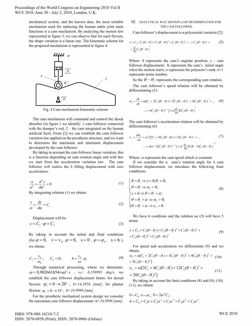
mechanical system, and the known data, the most suitable mechanism used for replacing the human ankle joint main functions is a cam mechanism. By analyzing the motion law represented in figure 3, we can observe that for each flexion, the shape variation is a linear one. The kinematic scheme for the proposed mechanism is represented in figure 4.
Fig. 4 Cam mechanism kinematic scheme.
The cam mechanism will command and control the shock
absorber (in figure 1 we identify: 1-cam follower connected with the dumper’s rod, 2 – the cam integrated on the human artificial foot). From [2] we can establish the cam follower variation law applied on the prosthesis structure, and we want to determine the maximum and minimum displacement developed by the cam follower.
By taking in account the cam follower linear variation, this is a function depending on cam rotation angle and with this we start from the acceleration variation law. The cam follower will realize the h lifting displacement with zero acceleration:
02
2
2 ==ϕω d
sda (1)
By integrating relation (1) we obtain:
1Cddsv
==ϕω
(2)
Displacement will be:
21 CCs +⋅= ϕ (3) By taking in account the initial and final conditions (for 0v v,0 ==ϕ , 0s ,0 ==ϕ , hs ,1 == ϕϕ ), we obtain:
10
20
01 ;0 ; ϕ
ωω⋅===
vhCvC (4)
Through numerical processing, where we determine: srad /902661654,8=ω , v0= 6,358993 deg/s, we
establish the cam follower displacement limits: for dorsal flexion: o2001 →=ϕ , h=14,2856 [mm]; for plantar flexion: o3501 →=ϕ , h=24,9998 [mm]. For the prosthetic mechanical system design we consider the maximum cam follower displacement: h=24,9998 [mm].
III. ANALYTICAL WAY MOTION LAW DETERMINATION FOR THE CAM FOLLOWER
Cam follower’s displacement is a polynomial variation [2]:
kn
kik
niniii
C
CCCCCs
∑=
−=
=−++−+−+−+=
0
33
2210
)(
)(...)()()(
θθ
θθθθθθθθ (5)
Where: θ represents the cam’s angular position; s – cam follower displacement; θi represents the cam’s initial angle when the motion starts; n represents the polynom’s rank; n+1 represents terms number. So the iθθ − represents the corresponding cam rotation. The cam follower’s speed relation will be obtained by differentiating (5):
kn
kik
nin
iii
KCnC
CCCCdtds
∑=
− −=−+
+−+−+−+==
0
1
34
23212
)(])(...
...)(4)(3)(2[
θθωθθ
θθθθθθωω (6)
The cam follower’s acceleration relation will be obtained by differentiating (6):
2
0
22
2432
222
)()1(])()1(...
...)(12)(62[
−
=
− ∑ −−=−−+
+−+−+==
kn
kik
nin
ii
CKKCnn
CCCdt
d
θθωθθ
θθθθωω
ε (7)
Where: ω represents the cam speed which is constant. If we consider the α cam’s rotation angle for h cam follower displacement, we introduce the following limit conditions:
⎪⎪⎪
⎩
⎪⎪⎪
⎨
⎧
=⇒+==⇒+=
+=⇒==⇒=
==⇒=
.0;0
;;0
;0;0
2
2
2
εαθθωαθθ
αθθωθθ
θθθ
i
i
i
i
ii
hs
s
(8)
We have 6 condtions and the relation no (5) will have 5 terms:
55
44
33
2210
)()(
)()()(
ii
iii
CC
CCCCs
θθθθ
θθθθθθ
−+−+
+−+−+−+= (9)
For speed and acceleration we differentiate (9) and we obtain:
])(5
)(4)(3)(2[4
5
34
23212
i
iii
C
CCCC
θθ
θθθθθθωω
−+
+−+−+−+= (10)
])(20
)(12)(62[3
5
24322
i
ii
C
CCC
θθ
θθθθωε
−+
+−+−+= (11)
By taking in account the limit conditions (8) and (9), (10), (11), we obtain:
.0 0C= .0 1Cω= .20 22Cω=
.55
44
33
2210 ααααα CCCCCCh +++++=
Proceedings of the World Congress on Engineering 2010 Vol II WCE 2010, June 30 - July 2, 2010, London, U.K.
ISBN: 978-988-18210-7-2 ISSN: 2078-0958 (Print); ISSN: 2078-0966 (Online)
WCE 2010
).5432(0 45
34
2321 ααααω CCCCC ++++= (12)
).201262(0 35
2432
2 αααω CCCC +++= From equations no (12) we obtain:
;00 =C ;01 =C .02 =C (13)
⎪⎪⎪
⎩
⎪⎪⎪
⎨
⎧
=
−=
=
.6
;15
;10
55
44
33
α
α
α
hC
hC
hC
By introducing the terms from (13) in (9), (10) and (11):
.
.61510543
αθθθα
θθα
θθα
θθ
+≤≤
⎟⎠⎞
⎜⎝⎛ −
+⎟⎠⎞
⎜⎝⎛ −
−⎟⎠⎞
⎜⎝⎛ −
=
ii
iii hhhs (14)
.306030 4322
2⎥⎥⎦
⎤
⎢⎢⎣
⎡⎟⎠⎞
⎜⎝⎛ −
⎟⎠⎞
⎜⎝⎛+⎟
⎠⎞
⎜⎝⎛ −
⎟⎠⎞
⎜⎝⎛−⎟
⎠⎞
⎜⎝⎛ −
⎟⎠⎞
⎜⎝⎛=
αθθ
ααθθ
ααθθ
αωω iii hhh (15)
.12018060 3
2
2
222
2⎥⎥⎦
⎤
⎢⎢⎣
⎡⎟⎠⎞
⎜⎝⎛ −
⎟⎠⎞
⎜⎝⎛+⎟
⎠⎞
⎜⎝⎛ −
⎟⎠⎞
⎜⎝⎛−⎟
⎠⎞
⎜⎝⎛ −
⎟⎠⎞
⎜⎝⎛=
αθθ
ααθθ
ααθθ
αωε iii hhh (16)
By differentiating (16) we obtain the pulsation:
.36036060 2
3333
⎥⎥⎦
⎤
⎢⎢⎣
⎡⎟⎠⎞
⎜⎝⎛ −
⎟⎠⎞
⎜⎝⎛+⎟
⎠⎞
⎜⎝⎛ −
⎟⎠⎞
⎜⎝⎛−⎟
⎠⎞
⎜⎝⎛=
αθθ
ααθθ
ααω ii hhhpuls (17)
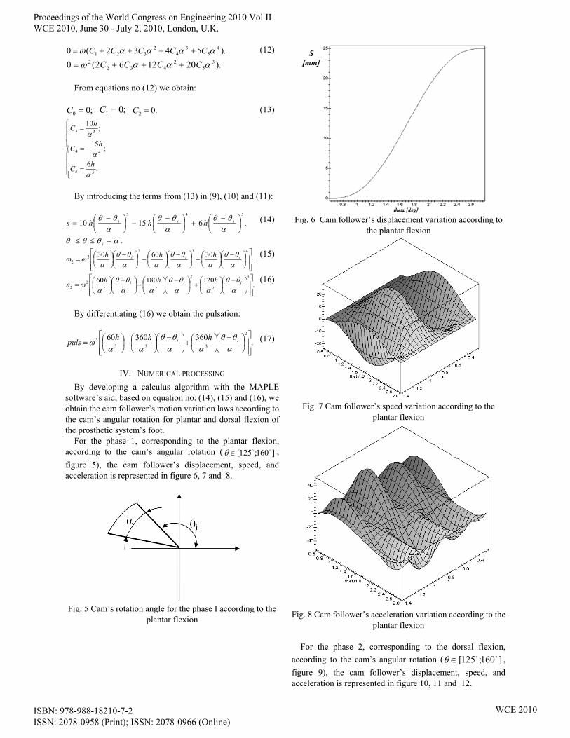
IV. NUMERICAL PROCESSING By developing a calculus algorithm with the MAPLE
software’s aid, based on equation no. (14), (15) and (16), we obtain the cam follower’s motion variation laws according to the cam’s angular rotation for plantar and dorsal flexion of the prosthetic system’s foot.
For the phase 1, corresponding to the plantar flexion, according to the cam’s angular rotation ( ]160;125[ oo∈θ , figure 5), the cam follower’s displacement, speed, and acceleration is represented in figure 6, 7 and 8.
Fig. 5 Cam’s rotation angle for the phase I according to the
plantar flexion
Fig. 6 Cam follower’s displacement variation according to
the plantar flexion
Fig. 7 Cam follower’s speed variation according to the
plantar flexion
Fig. 8 Cam follower’s acceleration variation according to the
plantar flexion
For the phase 2, corresponding to the dorsal flexion, according to the cam’s angular rotation ( ]160;125[ oo∈θ , figure 9), the cam follower’s displacement, speed, and acceleration is represented in figure 10, 11 and 12.
Proceedings of the World Congress on Engineering 2010 Vol II WCE 2010, June 30 - July 2, 2010, London, U.K.
ISBN: 978-988-18210-7-2 ISSN: 2078-0958 (Print); ISSN: 2078-0966 (Online)
WCE 2010
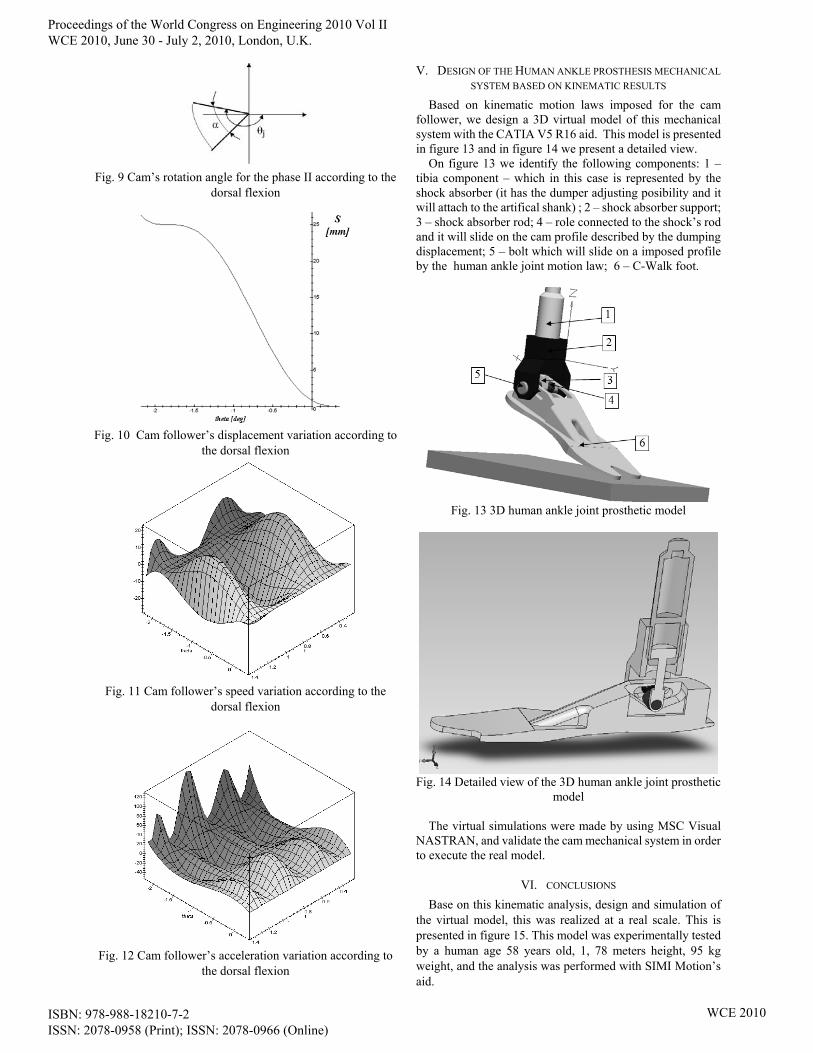
Fig. 9 Cam’s rotation angle for the phase II according to the
dorsal flexion
Fig. 10 Cam follower’s displacement variation according to
the dorsal flexion
Fig. 11 Cam follower’s speed variation according to the
dorsal flexion
Fig. 12 Cam follower’s acceleration variation according to
the dorsal flexion
V. DESIGN OF THE HUMAN ANKLE PROSTHESIS MECHANICAL SYSTEM BASED ON KINEMATIC RESULTS
Based on kinematic motion laws imposed for the cam follower, we design a 3D virtual model of this mechanical system with the CATIA V5 R16 aid. This model is presented in figure 13 and in figure 14 we present a detailed view. On figure 13 we identify the following components: 1 – tibia component – which in this case is represented by the shock absorber (it has the dumper adjusting posibility and it will attach to the artifical shank) ; 2 – shock absorber support; 3 – shock absorber rod; 4 – role connected to the shock’s rod and it will slide on the cam profile described by the dumping displacement; 5 – bolt which will slide on a imposed profile by the human ankle joint motion law; 6 – C-Walk foot.
Fig. 13 3D human ankle joint prosthetic model
Fig. 14 Detailed view of the 3D human ankle joint prosthetic
model
The virtual simulations were made by using MSC Visual NASTRAN, and validate the cam mechanical system in order to execute the real model.
VI. CONCLUSIONS Base on this kinematic analysis, design and simulation of
the virtual model, this was realized at a real scale. This is presented in figure 15. This model was experimentally tested by a human age 58 years old, 1, 78 meters height, 95 kg weight, and the analysis was performed with SIMI Motion’s aid.
Proceedings of the World Congress on Engineering 2010 Vol II WCE 2010, June 30 - July 2, 2010, London, U.K.
ISBN: 978-988-18210-7-2 ISSN: 2078-0958 (Print); ISSN: 2078-0966 (Online)
WCE 2010

The experimental analysis was performed in two stages: the preliminary stage when the human subject tries to walk for the first time, and the final stage, after 2 weeks, when the human subject walk each day with the new mechanical system (figure 16).
Fig. 15 The ankle joint prosthesis new real model
Fig. 16 Testing the prosthesis with the SIMI Motion’s aid.
In figure 17 is presented the human ankle joint motion law for walking process obtained with SIMI Motion’s aid for a healthy subject. In figure 18 is presented the new prosthesis ankle joint variation law obtained with the same software in the same conditions. The final conclusions are: - obtaining a new mechanical system which has on its
structure a cam mechanism; - the developed mechanical system is simple and a low cost
on execution; - the shock absorber was integrated in the prosthesis
resistance structure; - by analyzing the diagrams from figure 16 and 17 we
conclude that the angular amplitude values respect the theoretical ones from the medicine literature (the theoretic angular amplitude is about 45 – 50 degrees, and the new mechanical system’s amplitude is about 42 degrees);
- the new mechanical system respects the dimensional conditions imposed by a human lower limb;
- this is a patent solution and validate the use of cam
mechanisms in the human prostheses structures.
Fig. 17 Human ankle joint variation law from a healthy
subject
Fig. 18 Human ankle joint variation law developed by the
new prosthetic mechanical system
ACKNOWLEDGMENT
The research work reported here was made possible by Grant CNCSIS –UEFISCSU, project number PNII – IDEI code 401/2008.
REFERENCES [1] Copilusi C., “Research regarding applicable mechanical systems in
medicine”, Phd thesis, 2009. [2] Dumitru N., Nanu Ghe., Vintilă D., Mecanisme şi transmisii mecanice.
Tehnici de modelare clasice şi moderne. Editura Didactică şi Pedagogică. Bucureşti, 2008.
[3] Sameer Singh, Intelligent Robotics For Rehabilitation Robotic Lower Limb for Above Knee Prosthesis. Grant type (83/ECE/2000) Department of Electronics and Communication Engineering India, 2004.
[4] T. McGeer, Passive dynamic walking. International Journal of Robotics Research, vol. 9, no. 2, 1990, pp. 62-82.
[5] Wilson A.B., Limb prosthetics, artificial limb. Spring Verllag, 1994. [6] J. Moreno, K. Meijer, H. Savelberg, and J. Pons, Characterization of an
actuator system for a controllable knee ankle foot orthosis. Proceedings of 8th International Conference ACTUATOR, 2004, Bremen.
[7] M. Hardt, K. Kreutz-Delgado, J. Helton and O.V. Stryk, Obtaining minimum energy biped walking gaits with symbolic models and numerical optimal control. Workshop - Biomechanics Meets Robotics, Modelling and Simulation of Motion, HeidelBerg, Germany. 1999. pp. 1–19.
[8] Williams M., Biomechanics of human motion. W.B. Saunders Co. Philadelphia and London, 1996.
[9] SouthWest Orthotic Centre. Available: http://www.southwest-ortho.com
[10] Otto Bock Prosthetic Centre http://www.ottobock.com [11] Bauerfeind Research Center AG Germany http://www.bauerfeind.com [12] Blatchford prosthetics institution http://www. blatchford.co.uk [13] Ohio Willow Wood Prosthetic Centre http://www.owwco.com [14] SIMI Motion http://www.simi.com
Proceedings of the World Congress on Engineering 2010 Vol II WCE 2010, June 30 - July 2, 2010, London, U.K.
ISBN: 978-988-18210-7-2 ISSN: 2078-0958 (Print); ISSN: 2078-0966 (Online)
WCE 2010