
Cam Bien Tiem Can Dung
26
54 Cap aci ti ve P roxim i ty Sen sor s T h eory o f Ope r a t i on Capacitive proximity sensors are similar to inductive proximity sensors. The main difference between the two types is that capa citive prox imity sensors produ ce an electrostatic field instead of an electromagnetic field. Capacitive proximity switches will sense metal as well as nonmetallic materials such as paper, glass, liquids, and cloth. T h e sen si ng su r fa ce o f a capa ci t iv e sensor i s f o r me d b y two concentrically shaped metal electrodes of an unwound capacitor. When an object nears the sensing surface it enters the electrostatic field of the electrodes and changes the capacitance in an oscillator circuit. As a result, the oscillator begins oscillating. The trigger circuit read s the oscillator’ s amplitude and when it reaches a specific level the output state of the sensor changes. As the target moves away from the sensor the oscillator’s amplitude decreases, switching the sensor output back to its original state.
Transcript of Cam Bien Tiem Can Dung
8/11/2019 Cam Bien Tiem Can Dung
http://slidepdf.com/reader/full/cam-bien-tiem-can-dung 1/26
54
Capacitive Proximity Sensors Theory of Operation
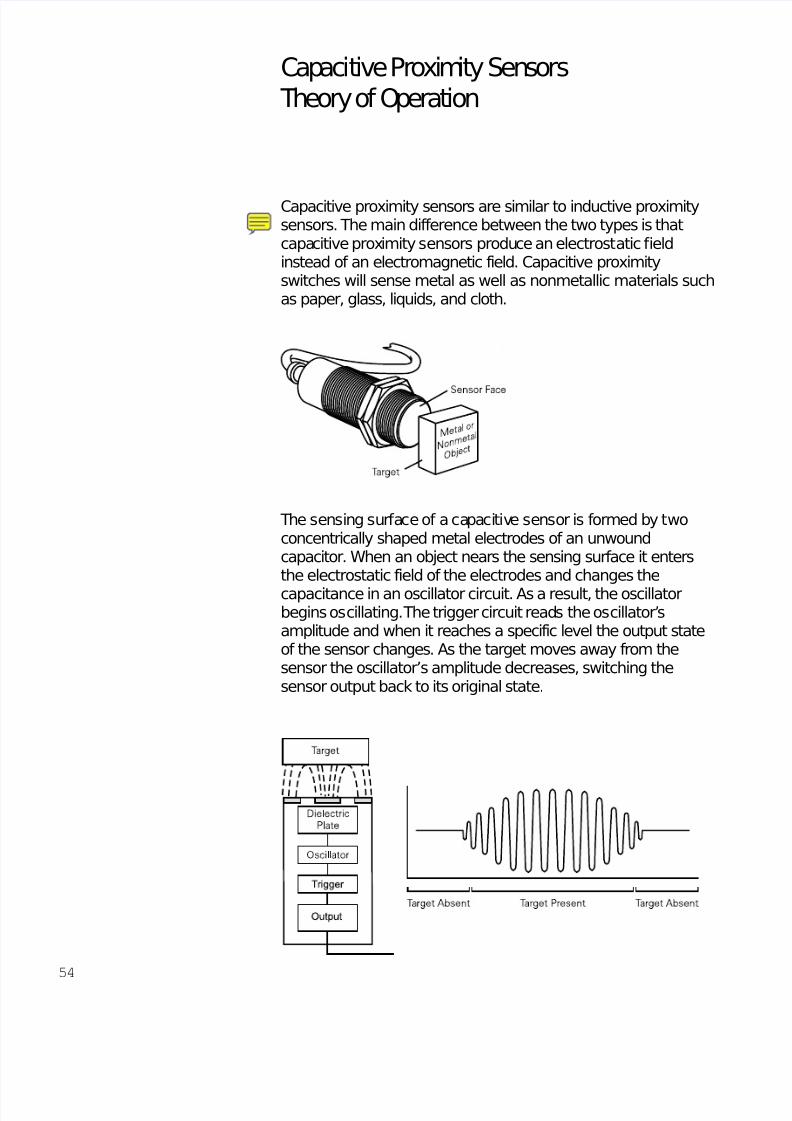
Capacitive proximity sensors are similar to inductive proximitysensors. The main difference between the two types is thatcapacitive proximity sensors produce an electrostatic fieldinstead of an electromagnetic field. Capacitive proximityswitches will sense metal as well as nonmetallic materials suchas paper, glass, liquids, and cloth.
The sensing surface of a capacitive sensor is formed by twoconcentrically shaped metal electrodes of an unwoundcapacitor. When an object nears the sensing surface it entersthe electrostatic field of the electrodes and changes the
capacitance in an oscillator circuit. As a result, the oscillatorbegins oscillating. The trigger circuit reads the oscillator’samplitude and when it reaches a specific level the output stateof the sensor changes. As the target moves away from thesensor the oscillator’s amplitude decreases, switching thesensor output back to its original state.
8/11/2019 Cam Bien Tiem Can Dung
http://slidepdf.com/reader/full/cam-bien-tiem-can-dung 2/26
55
Standard Target and Standard targets are specified for each capacitive sensor. TheDielectric Constant standard target is usually defined as metal and/or water.
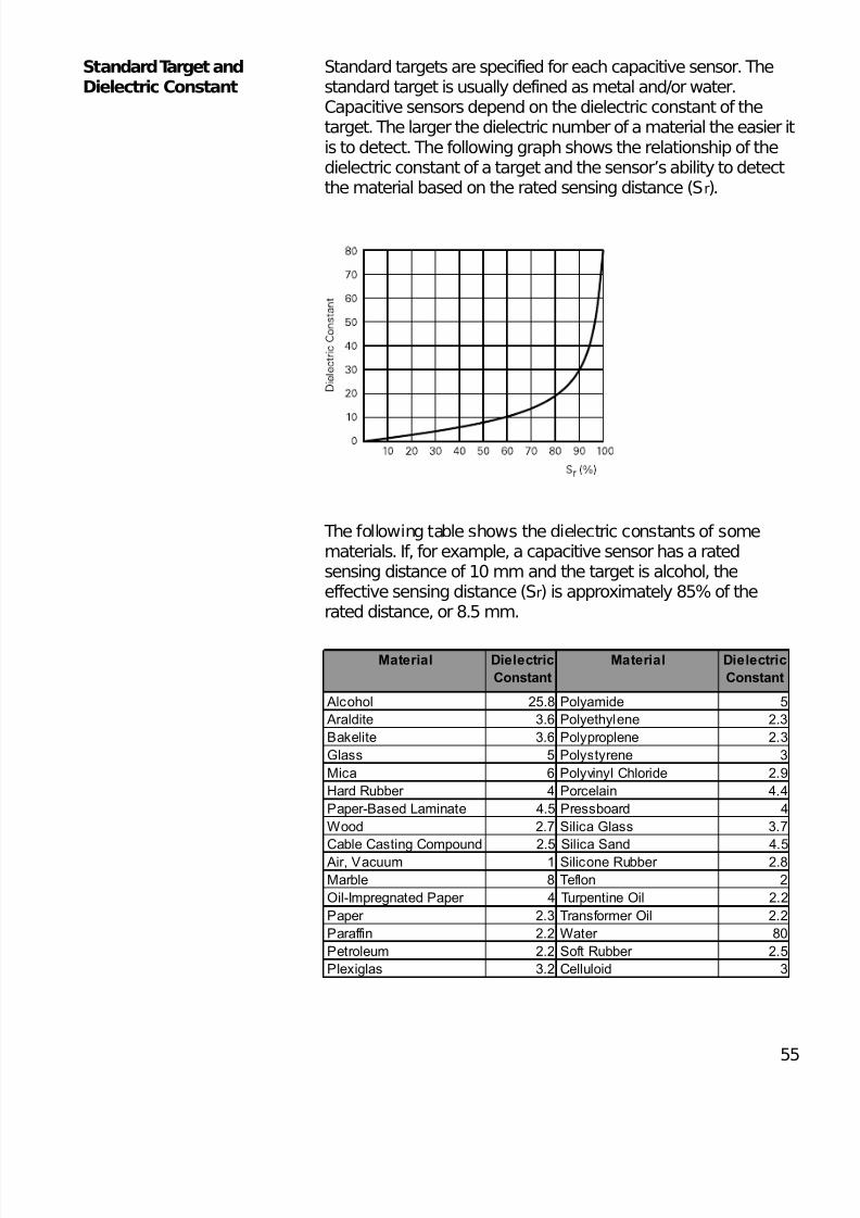
Capacitive sensors depend on the dielectric constant of thetarget. The larger the dielectric number of a material the easier itis to detect. The following graph shows the relationship of thedielectric constant of a target and the sensor’s ability to detectthe material based on the rated sensing distance (Sr).
The following table shows the dielectric constants of somematerials. If, for example, a capacitive sensor has a ratedsensing distance of 10 mm and the target is alcohol, theeffective sensing distance (Sr) is approximately 85% of therated distance, or 8.5 mm.
Material Dielectric
Constant
Material Dielectric
Constant
Alcohol 25.8 Polyamide 5
Araldite 3.6 Polyethylene 2.3
Bakelite 3.6 Polyproplene 2.3
Glass 5 Polystyrene 3
Mica 6 Polyvinyl Chloride 2.9
Hard Rubber 4 Porcelain 4.4
Paper-Based Laminate 4.5 Pressboard 4
Wood 2.7 Silica Glass 3.7
Cable Casting Compound 2.5 Silica Sand 4.5
Air, Vacuum 1 Silicone Rubber 2.8
Marble 8 Teflon 2
Oil-Impregnated Paper 4 Turpentine Oil 2.2
Paper 2.3 Transformer Oil 2.2
Paraffin 2.2 Water 80
Petroleum 2.2 Soft Rubber 2.5
Plexiglas 3.2 Celluloid 3
8/11/2019 Cam Bien Tiem Can Dung
http://slidepdf.com/reader/full/cam-bien-tiem-can-dung 3/26
56
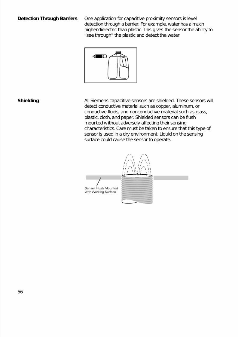
Detection Through Barriers One application for capacitive proximity sensors is leveldetection through a barrier. For example, water has a muchhigher dielectric than plastic. This gives the sensor the ability to“see through” the plastic and detect the water.
Shielding All Siemens capacitive sensors are shielded. These sensors willdetect conductive material such as copper, aluminum, orconductive fluids, and nonconductive material such as glass,
plastic, cloth, and paper. Shielded sensors can be flushmounted without adversely affecting their sensingcharacteristics. Care must be taken to ensure that this type of sensor is used in a dry environment. Liquid on the sensingsurface could cause the sensor to operate.
8/11/2019 Cam Bien Tiem Can Dung
http://slidepdf.com/reader/full/cam-bien-tiem-can-dung 4/26
57
Capacitive Proximity Sensor Family
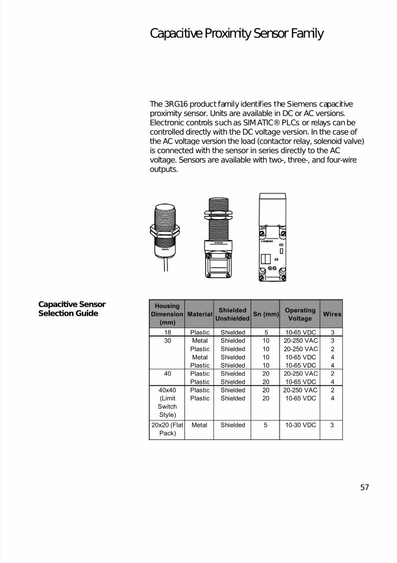
The 3RG16 product family identifies the Siemens capacitiveproximity sensor. Units are available in DC or AC versions.Electronic controls such as SIMATIC® PLCs or relays can becontrolled directly with the DC voltage version. In the case of the AC voltage version the load (contactor relay, solenoid valve)is connected with the sensor in series directly to the ACvoltage. Sensors are available with two-, three-, and four-wireoutputs.
Capacitive SensorSelection Guide
Housing
Dimension
(mm)
MaterialShielded
UnshieldedSn (mm)
Operating
VoltageWires
18 Plastic Shielded 5 10-65 VDC 3
Metal Shielded 10 20-250 VAC 3
Plastic Shielded 10 20-250 VAC 2
Metal Shielded 10 10-65 VDC 4
Plastic Shielded 10 10-65 VDC 4
Plastic Shielded 20 20-250 VAC 2
Plastic Shielded 20 10-65 VDC 4
Plastic Shielded 20 20-250 VAC 2
Plastic Shielded 20 10-65 VDC 4
20x20 (Flat
Pack)
Metal Shielded 5 10-30 VDC 3
30
40x40
(Limit
Switch
Style)
40
8/11/2019 Cam Bien Tiem Can Dung
http://slidepdf.com/reader/full/cam-bien-tiem-can-dung 5/26
58
Review 41) A main difference between an inductive proximity
sensor and a capacitive proximity sensor is that acapacitive proximity sensor produces an ____________ field.
2) Capacitive proximity sensors will sense ____________
material.
3) The larger the ____________ constant of a material theeasier it is for a capacitive proximity sense to detect.
4) It is easier for a capacitive proximity sensor to detect ____________ than porcelain.
a. teflonb.marblec.petroleum
d.paper
5) The maximum rated sensing distance of a capacitiveproximity sensor is ____________ mm.
8/11/2019 Cam Bien Tiem Can Dung
http://slidepdf.com/reader/full/cam-bien-tiem-can-dung 6/26
59
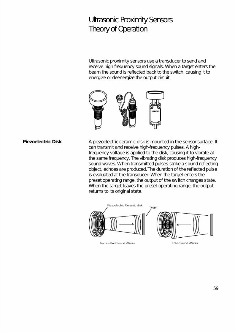
Ultrasonic Proximity Sensors Theory of Operation
Ultrasonic proximity sensors use a transducer to send andreceive high frequency sound signals. When a target enters thebeam the sound is reflected back to the switch, causing it toenergize or deenergize the output circuit.
Piezoelectric Disk A piezoelectric ceramic disk is mounted in the sensor surface. Itcan transmit and receive high-frequency pulses. A high-frequency voltage is applied to the disk, causing it to vibrate atthe same frequency. The vibrating disk produces high-frequencysound waves. When transmitted pulses strike a sound-reflectingobject, echoes are produced. The duration of the reflected pulse
is evaluated at the transducer. When the target enters thepreset operating range, the output of the switch changes state.When the target leaves the preset operating range, the outputreturns to its original state.
8/11/2019 Cam Bien Tiem Can Dung
http://slidepdf.com/reader/full/cam-bien-tiem-can-dung 7/26
60
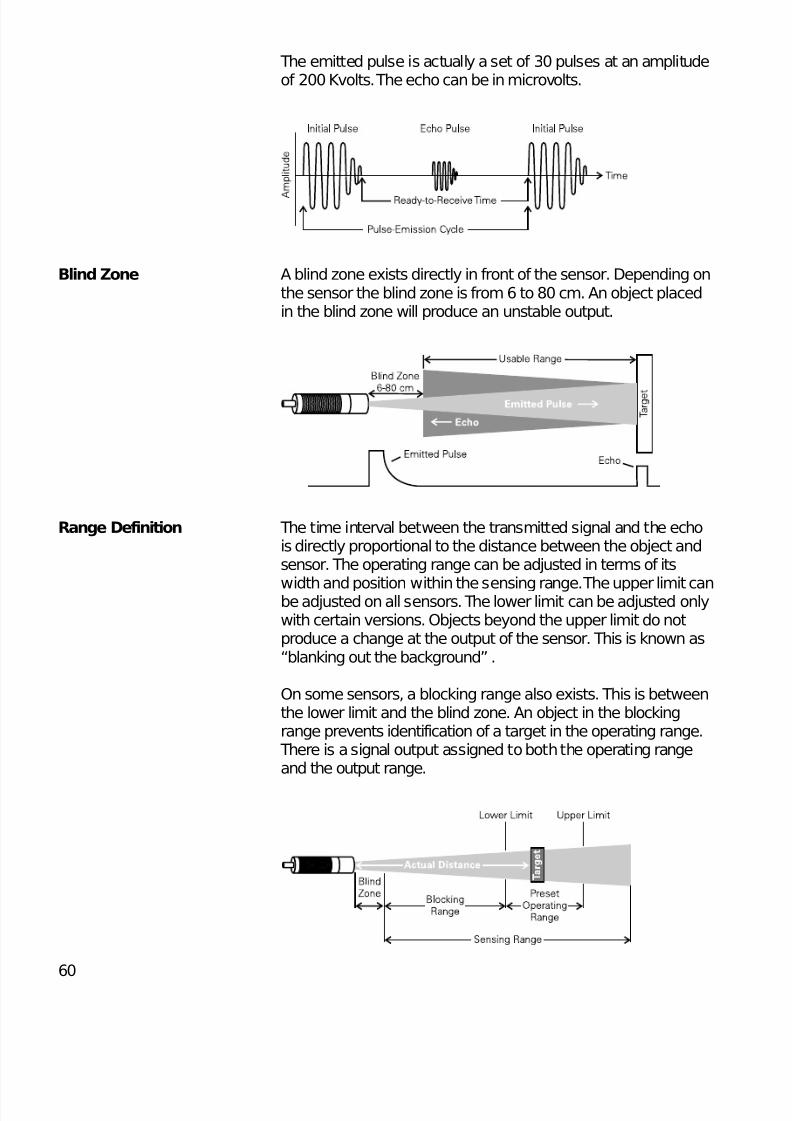
The emitted pulse is actually a set of 30 pulses at an amplitudeof 200 Kvolts. The echo can be in microvolts.
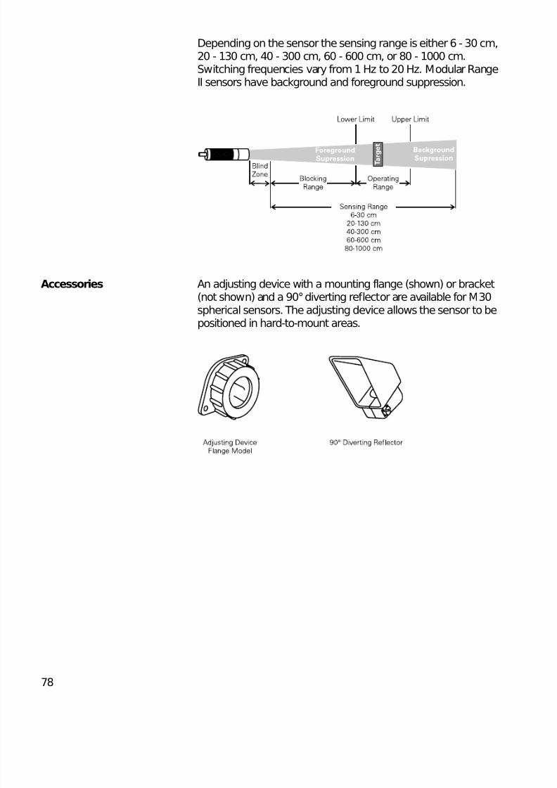
Blind Zone A blind zone exists directly in front of the sensor. Depending onthe sensor the blind zone is from 6 to 80 cm. An object placedin the blind zone will produce an unstable output.
Range Definition The time interval between the transmitted signal and the echois directly proportional to the distance between the object andsensor. The operating range can be adjusted in terms of its
width and position within the sensing range. The upper limit canbe adjusted on all sensors. The lower limit can be adjusted onlywith certain versions. Objects beyond the upper limit do notproduce a change at the output of the sensor. This is known as“blanking out the background” .
On some sensors, a blocking range also exists. This is betweenthe lower limit and the blind zone. An object in the blockingrange prevents identification of a target in the operating range. There is a signal output assigned to both the operating rangeand the output range.
8/11/2019 Cam Bien Tiem Can Dung
http://slidepdf.com/reader/full/cam-bien-tiem-can-dung 8/26
61
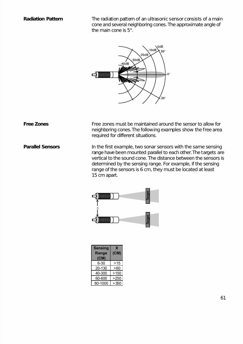
Radiation Pattern The radiation pattern of an ultrasonic sensor consists of a maincone and several neighboring cones. The approximate angle of the main cone is 5°.
Free Zones Free zones must be maintained around the sensor to allow forneighboring cones. The following examples show the free arearequired for different situations.
Parallel Sensors In the first example, two sonar sensors with the same sensingrange have been mounted parallel to each other. The targets arevertical to the sound cone. The distance between the sensors isdetermined by the sensing range. For example, if the sensingrange of the sensors is 6 cm, they must be located at least15 cm apart.
X
T a r g e t
T a r g e t
Sensing
Range
(CM)
X
(CM)
6-30 >15
20-130 >60
40-300 >150
60-600 >250
80-1000 >350
8/11/2019 Cam Bien Tiem Can Dung
http://slidepdf.com/reader/full/cam-bien-tiem-can-dung 9/26
62
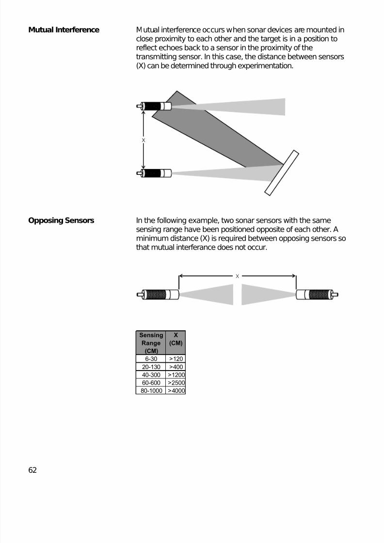
Mutual Interference Mutual interference occurs when sonar devices are mounted inclose proximity to each other and the target is in a position toreflect echoes back to a sensor in the proximity of thetransmitting sensor. In this case, the distance between sensors(X) can be determined through experimentation.
Opposing Sensors In the following example, two sonar sensors with the samesensing range have been positioned opposite of each other. Aminimum distance (X) is required between opposing sensors sothat mutual interferance does not occur.
X
Sensing
Range
(CM)
X
(CM)
6-30 >120
20-130 >400
40-300 >1200
60-600 >2500
80-1000 >4000
8/11/2019 Cam Bien Tiem Can Dung
http://slidepdf.com/reader/full/cam-bien-tiem-can-dung 10/26
8/11/2019 Cam Bien Tiem Can Dung
http://slidepdf.com/reader/full/cam-bien-tiem-can-dung 11/26
64
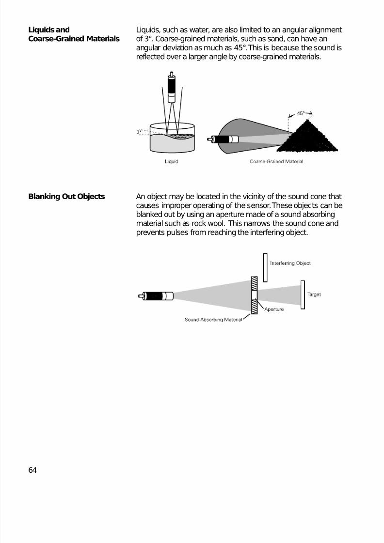
Liquids and Liquids, such as water, are also limited to an angular alignmentCoarse-Grained Materials of 3°. Coarse-grained materials, such as sand, can have an
angular deviation as much as 45°. This is because the sound isreflected over a larger angle by coarse-grained materials.
Blanking Out Objects An object may be located in the vicinity of the sound cone thatcauses improper operating of the sensor. These objects can beblanked out by using an aperture made of a sound absorbingmaterial such as rock wool. This narrows the sound cone andprevents pulses from reaching the interfering object.
8/11/2019 Cam Bien Tiem Can Dung
http://slidepdf.com/reader/full/cam-bien-tiem-can-dung 12/26
65
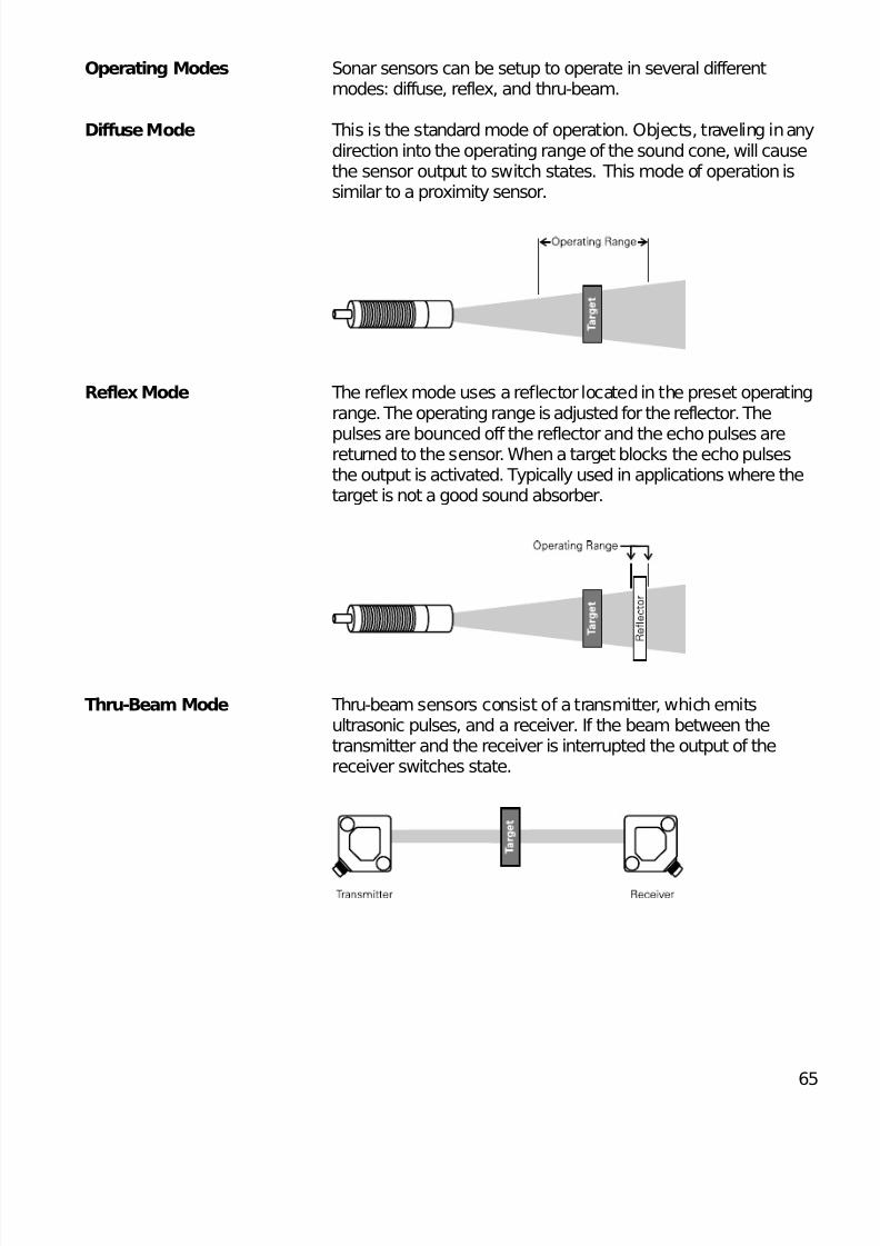
Operating Modes Sonar sensors can be setup to operate in several differentmodes: diffuse, reflex, and thru-beam.
Diffuse Mode This is the standard mode of operation. Objects, traveling in anydirection into the operating range of the sound cone, will causethe sensor output to switch states. This mode of operation issimilar to a proximity sensor.
Reflex Mode The reflex mode uses a reflector located in the preset operatingrange. The operating range is adjusted for the reflector. The
pulses are bounced off the reflector and the echo pulses arereturned to the sensor. When a target blocks the echo pulsesthe output is activated. Typically used in applications where thetarget is not a good sound absorber.
Thru-Beam Mode Thru-beam sensors consist of a transmitter, which emitsultrasonic pulses, and a receiver. If the beam between thetransmitter and the receiver is interrupted the output of thereceiver switches state.
8/11/2019 Cam Bien Tiem Can Dung
http://slidepdf.com/reader/full/cam-bien-tiem-can-dung 13/26
66
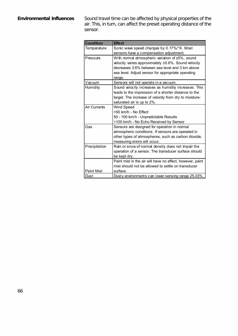
Environmental Influences Sound travel time can be affected by physical properties of theair. This, in turn, can affect the preset operating distance of thesensor.
Condition Effect
Temperature Sonic wave speed changes by 0.17%/°K. Most
sensors have a compensation adjustment.
Pressure With normal atmospheric variation of ±5%, soundvelocity varies approximately ±0.6%. Sound velocity
decreases 3.6% between sea level and 3 km above
sea level. Adjust sensor for appropriate operating
range.
Vacuum Sensors will not operate in a vacuum.
Humidity Sound velocity increases as humidity increases. This
leads to the impression of a shorter distance to the
target. The increase of velocity from dry to moisture-
saturated air is up to 2%.
Wind Speed
<50 km/h - No Effect
50 - 100 km/h - Unpredictable Results>100 km/h - No Echo Received by Sensor
Gas Sensors are designed for operation in normal
atmospheric conditions. If sensors are operated in
other types of atmospheres, such as carbon dioxide,
measuring errors will occur.
Precipitation Rain or snow of normal density does not impair the
operation of a sensor. The transducer surface should
be kept dry.
Paint Mist
Paint mist in the air will have no effect, however, paint
mist should not be allowed to settle on transducer
surface.
Dust Dusty environments can lower sensing range 25-33%.
Air Currents
8/11/2019 Cam Bien Tiem Can Dung
http://slidepdf.com/reader/full/cam-bien-tiem-can-dung 14/26
67
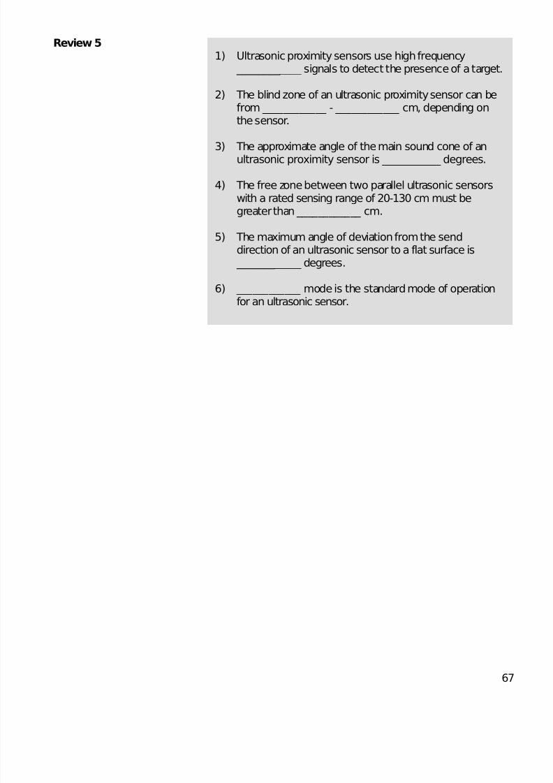
Review 51) Ultrasonic proximity sensors use high frequency
____________ signals to detect the presence of a target.
2) The blind zone of an ultrasonic proximity sensor can befrom ____________ - ____________ cm, depending onthe sensor.
3) The approximate angle of the main sound cone of anultrasonic proximity sensor is ____________ degrees.
4) The free zone between two parallel ultrasonic sensorswith a rated sensing range of 20-130 cm must begreater than ____________ cm.
5) The maximum angle of deviation from the senddirection of an ultrasonic sensor to a flat surface is ____________ degrees.
6) ____________ mode is the standard mode of operationfor an ultrasonic sensor.
8/11/2019 Cam Bien Tiem Can Dung
http://slidepdf.com/reader/full/cam-bien-tiem-can-dung 15/26
68
Ultrasonic Proximity Sensor Family
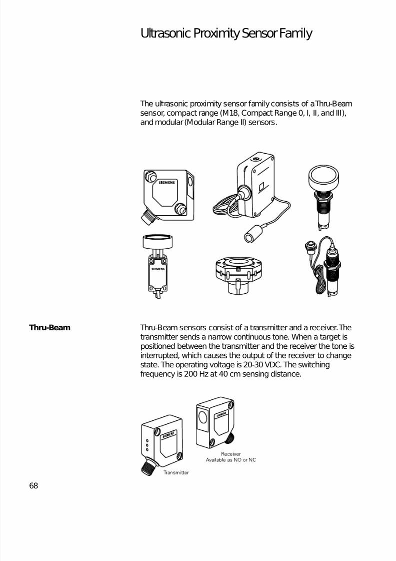
The ultrasonic proximity sensor family consists of a Thru-Beamsensor, compact range (M18, Compact Range 0, I, II, and III),and modular (Modular Range II) sensors.
Thru-Beam Thru-Beam sensors consist of a transmitter and a receiver. Thetransmitter sends a narrow continuous tone. When a target ispositioned between the transmitter and the receiver the tone isinterrupted, which causes the output of the receiver to changestate. The operating voltage is 20-30 VDC. The switchingfrequency is 200 Hz at 40 cm sensing distance.
8/11/2019 Cam Bien Tiem Can Dung
http://slidepdf.com/reader/full/cam-bien-tiem-can-dung 16/26
69
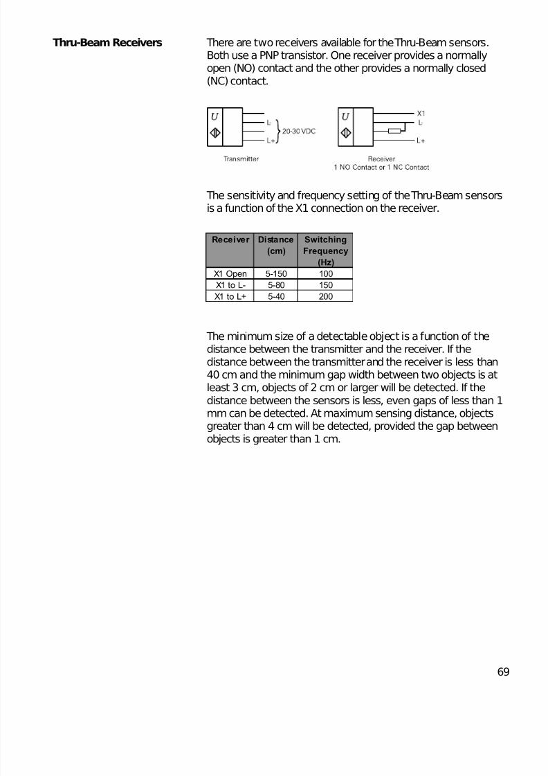
Thru-Beam Receivers There are two receivers available for the Thru-Beam sensors.Both use a PNP transistor. One receiver provides a normallyopen (NO) contact and the other provides a normally closed(NC) contact.
The sensitivity and frequency setting of the Thru-Beam sensorsis a function of the X1 connection on the receiver.
The minimum size of a detectable object is a function of thedistance between the transmitter and the receiver. If thedistance between the transmitter and the receiver is less than40 cm and the minimum gap width between two objects is atleast 3 cm, objects of 2 cm or larger will be detected. If thedistance between the sensors is less, even gaps of less than 1mm can be detected. At maximum sensing distance, objectsgreater than 4 cm will be detected, provided the gap betweenobjects is greater than 1 cm.
Receiver Distance
(cm)
Switching
Frequency
(Hz)
X1 Open 5-150 100X1 to L- 5-80 150
X1 to L+ 5-40 200
8/11/2019 Cam Bien Tiem Can Dung
http://slidepdf.com/reader/full/cam-bien-tiem-can-dung 17/26
70
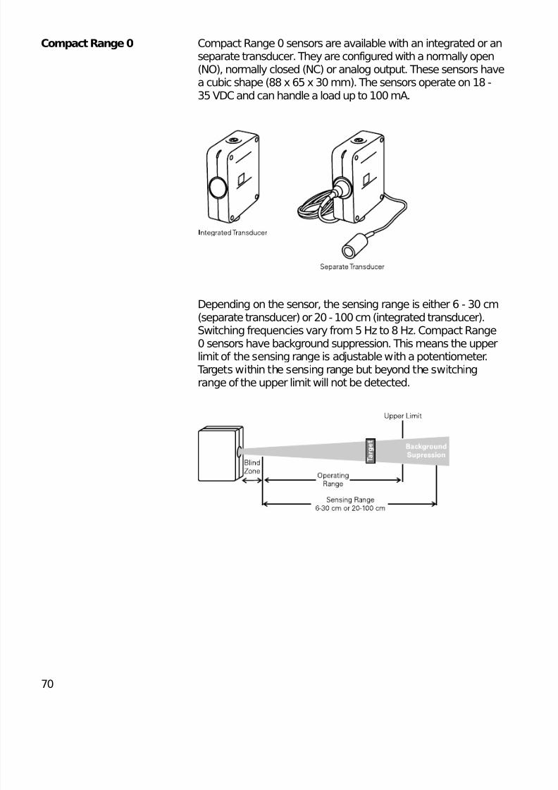
Compact Range 0 Compact Range 0 sensors are available with an integrated or anseparate transducer. They are configured with a normally open(NO), normally closed (NC) or analog output. These sensors havea cubic shape (88 x 65 x 30 mm). The sensors operate on 18 -35 VDC and can handle a load up to 100 mA.
Depending on the sensor, the sensing range is either 6 - 30 cm(separate transducer) or 20 - 100 cm (integrated transducer).Switching frequencies vary from 5 Hz to 8 Hz. Compact Range0 sensors have background suppression. This means the upperlimit of the sensing range is adjustable with a potentiometer. Targets within the sensing range but beyond the switchingrange of the upper limit will not be detected.
8/11/2019 Cam Bien Tiem Can Dung
http://slidepdf.com/reader/full/cam-bien-tiem-can-dung 18/26
71
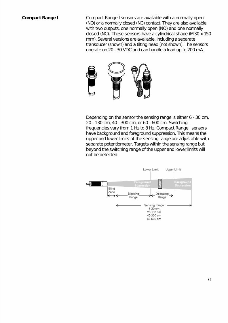
Compact Range I Compact Range I sensors are available with a normally open(NO) or a normally closed (NC) contact. They are also availablewith two outputs, one normally open (NO) and one normallyclosed (NC). These sensors have a cylindrical shape (M30 x 150mm). Several versions are available, including a separatetransducer (shown) and a tilting head (not shown). The sensorsoperate on 20 - 30 VDC and can handle a load up to 200 mA.
Depending on the sensor the sensing range is either 6 - 30 cm,20 - 130 cm, 40 - 300 cm, or 60 - 600 cm. Switchingfrequencies vary from 1 Hz to 8 Hz. Compact Range I sensorshave background and foreground suppression. This means theupper and lower limits of the sensing range are adjustable withseparate potentiometer. Targets within the sensing range butbeyond the switching range of the upper and lower limits willnot be detected.
8/11/2019 Cam Bien Tiem Can Dung
http://slidepdf.com/reader/full/cam-bien-tiem-can-dung 19/26
72
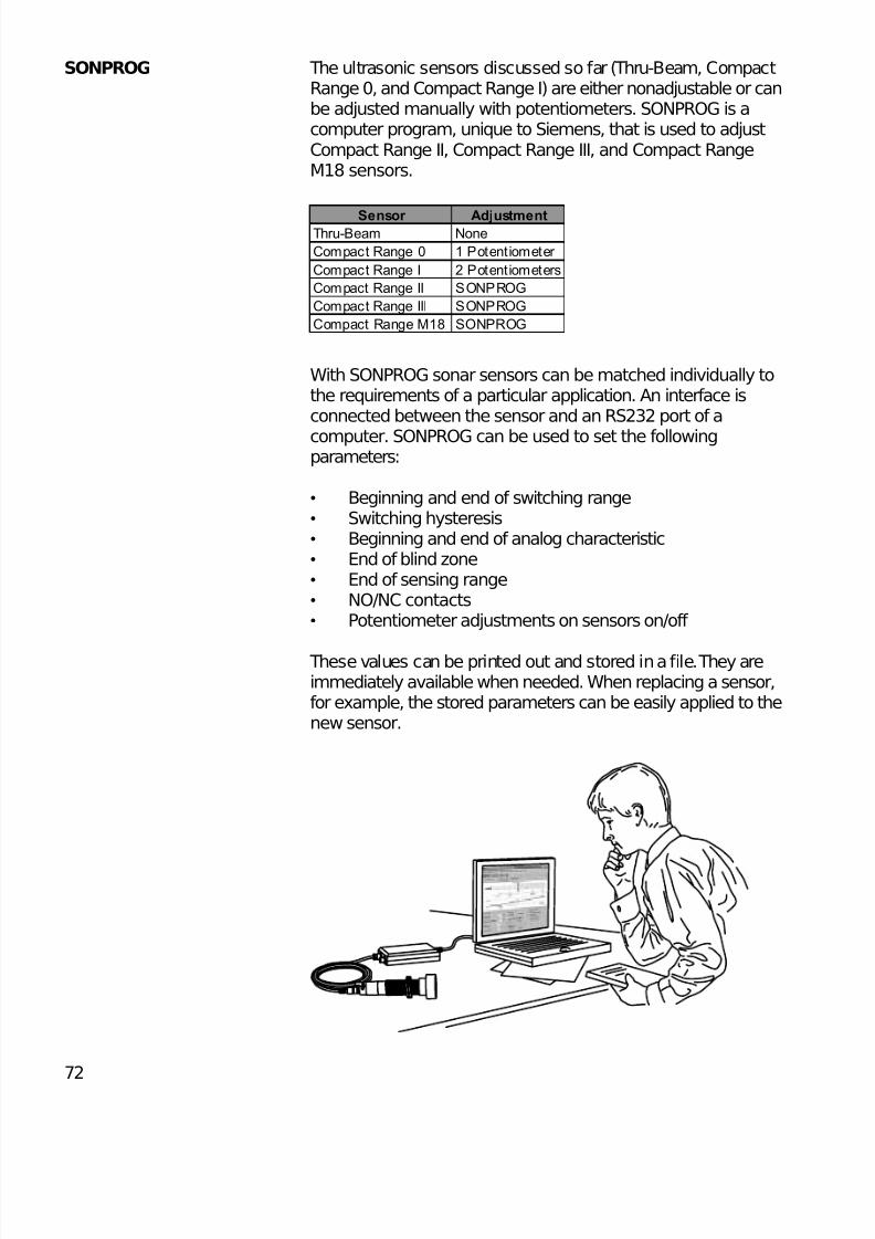
SONPROG The ultrasonic sensors discussed so far (Thru-Beam, CompactRange 0, and Compact Range I) are either nonadjustable or canbe adjusted manually with potentiometers. SONPROG is acomputer program, unique to Siemens, that is used to adjustCompact Range II, Compact Range III, and Compact RangeM18 sensors.
With SONPROG sonar sensors can be matched individually tothe requirements of a particular application. An interface isconnected between the sensor and an RS232 port of a
computer. SONPROG can be used to set the followingparameters:
• Beginning and end of switching range• Switching hysteresis• Beginning and end of analog characteristic• End of blind zone• End of sensing range• NO/NC contacts• Potentiometer adjustments on sensors on/off
These values can be printed out and stored in a file. They areimmediately available when needed. When replacing a sensor,for example, the stored parameters can be easily applied to thenew sensor.
Sensor AdjustmentThru-Beam None
Compact Range 0 1 Potentiometer
Compact Range I 2 Potentiometers
Compact Range II SONPROG
Compact Range III SONPROG
Compact Range M18 SONPROG
8/11/2019 Cam Bien Tiem Can Dung
http://slidepdf.com/reader/full/cam-bien-tiem-can-dung 20/26
73
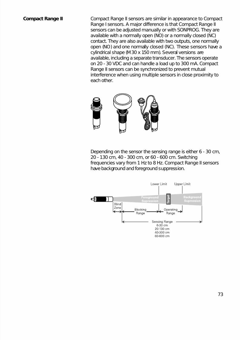
Compact Range II Compact Range II sensors are similar in appearance to CompactRange I sensors. A major difference is that Compact Range IIsensors can be adjusted manually or with SONPROG. They areavailable with a normally open (NO) or a normally closed (NC)contact. They are also available with two outputs, one normallyopen (NO) and one normally closed (NC). These sensors have acylindrical shape (M30 x 150 mm). Several versions are
available, including a separate transducer. The sensors operateon 20 - 30 VDC and can handle a load up to 300 mA. CompactRange II sensors can be synchronized to prevent mutualinterference when using multiple sensors in close proximity toeach other.
Depending on the sensor the sensing range is either 6 - 30 cm,20 - 130 cm, 40 - 300 cm, or 60 - 600 cm. Switchingfrequencies vary from 1 Hz to 8 Hz. Compact Range II sensorshave background and foreground suppression.
8/11/2019 Cam Bien Tiem Can Dung
http://slidepdf.com/reader/full/cam-bien-tiem-can-dung 21/26
74
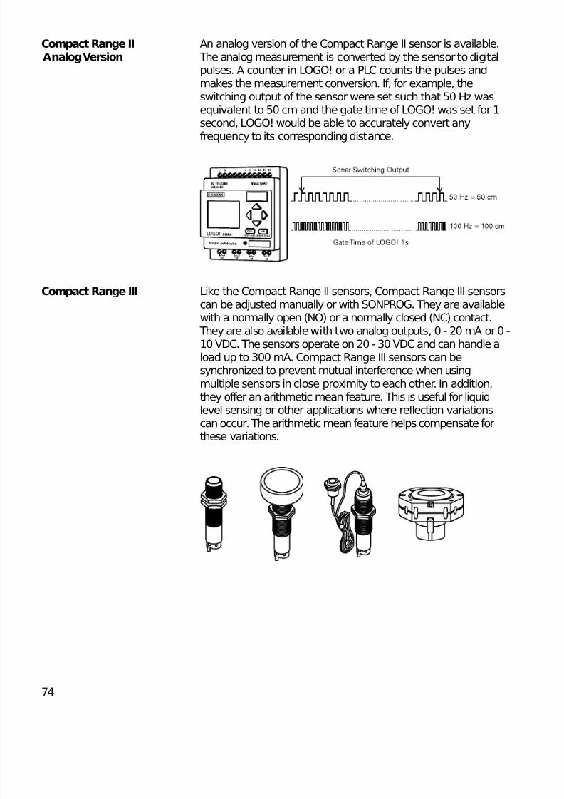
Compact Range II An analog version of the Compact Range II sensor is available. Analog Version The analog measurement is converted by the sensor to digital
pulses. A counter in LOGO! or a PLC counts the pulses andmakes the measurement conversion. If, for example, theswitching output of the sensor were set such that 50 Hz wasequivalent to 50 cm and the gate time of LOGO! was set for 1second, LOGO! would be able to accurately convert any
frequency to its corresponding distance.
Compact Range III Like the Compact Range II sensors, Compact Range III sensorscan be adjusted manually or with SONPROG. They are availablewith a normally open (NO) or a normally closed (NC) contact. They are also available with two analog outputs, 0 - 20 mA or 0 -10 VDC. The sensors operate on 20 - 30 VDC and can handle aload up to 300 mA. Compact Range III sensors can besynchronized to prevent mutual interference when usingmultiple sensors in close proximity to each other. In addition,they offer an arithmetic mean feature. This is useful for liquidlevel sensing or other applications where reflection variations
can occur. The arithmetic mean feature helps compensate forthese variations.
8/11/2019 Cam Bien Tiem Can Dung
http://slidepdf.com/reader/full/cam-bien-tiem-can-dung 22/26
75
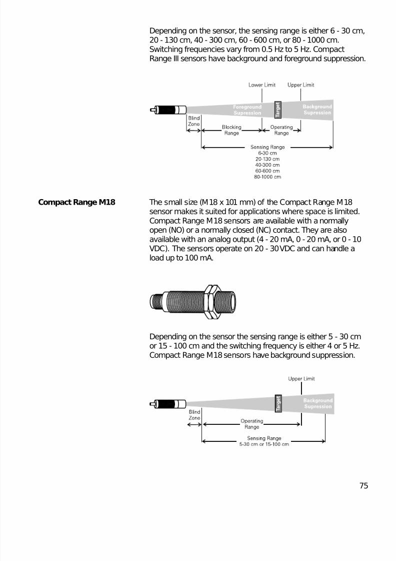
Depending on the sensor, the sensing range is either 6 - 30 cm,20 - 130 cm, 40 - 300 cm, 60 - 600 cm, or 80 - 1000 cm.Switching frequencies vary from 0.5 Hz to 5 Hz. CompactRange III sensors have background and foreground suppression.
Compact Range M18 The small size (M18 x 101 mm) of the Compact Range M18sensor makes it suited for applications where space is limited.Compact Range M18 sensors are available with a normallyopen (NO) or a normally closed (NC) contact. They are alsoavailable with an analog output (4 - 20 mA, 0 - 20 mA, or 0 - 10VDC). The sensors operate on 20 - 30 VDC and can handle aload up to 100 mA.
Depending on the sensor the sensing range is either 5 - 30 cmor 15 - 100 cm and the switching frequency is either 4 or 5 Hz.Compact Range M18 sensors have background suppression.
8/11/2019 Cam Bien Tiem Can Dung
http://slidepdf.com/reader/full/cam-bien-tiem-can-dung 23/26
76
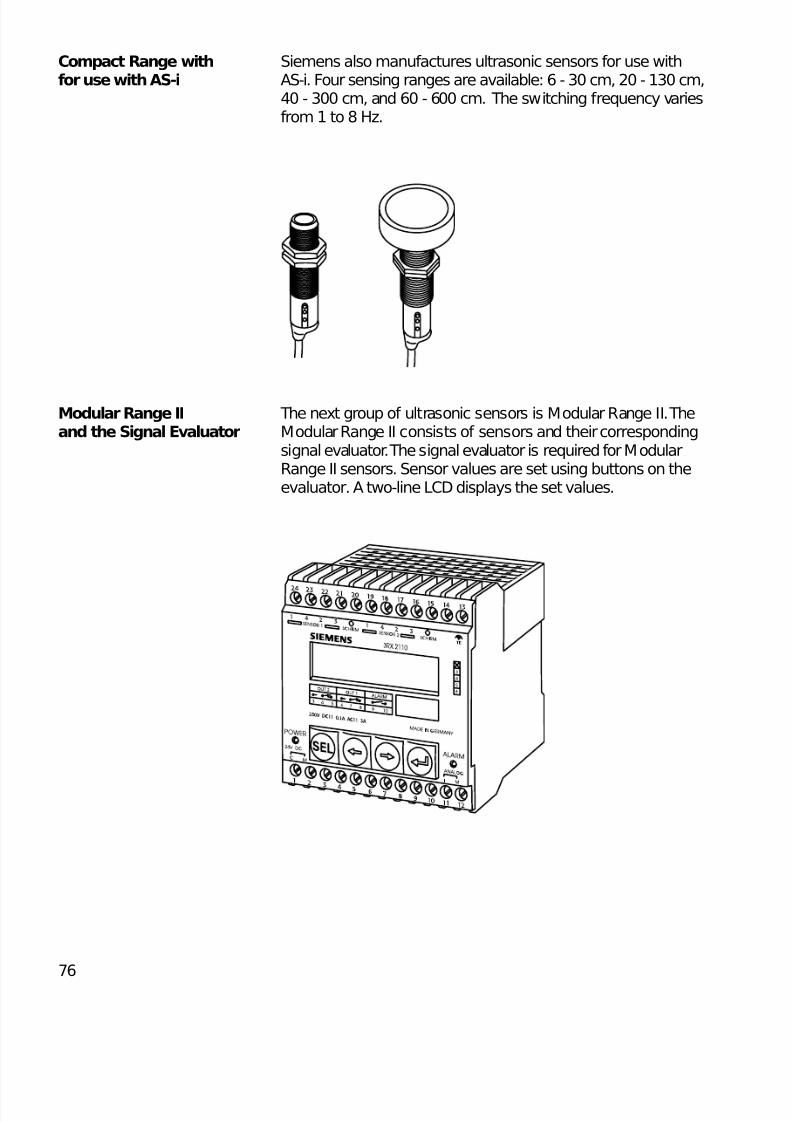
Compact Range with Siemens also manufactures ultrasonic sensors for use withfor use with AS-i AS-i. Four sensing ranges are available: 6 - 30 cm, 20 - 130 cm,
40 - 300 cm, and 60 - 600 cm. The switching frequency variesfrom 1 to 8 Hz.
Modular Range II The next group of ultrasonic sensors is Modular Range II. Theand the Signal Evaluator Modular Range II consists of sensors and their corresponding
signal evaluator. The signal evaluator is required for ModularRange II sensors. Sensor values are set using buttons on theevaluator. A two-line LCD displays the set values.
8/11/2019 Cam Bien Tiem Can Dung
http://slidepdf.com/reader/full/cam-bien-tiem-can-dung 24/26
77
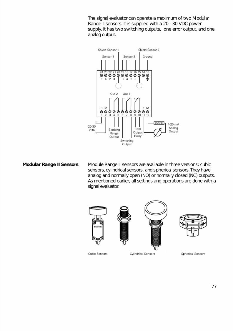
The signal evaluator can operate a maximum of two ModularRange II sensors. It is supplied with a 20 - 30 VDC powersupply. It has two switching outputs, one error output, and oneanalog output.
Modular Range II Sensors Module Range II sensors are available in three versions: cubicsensors, cylindrical sensors, and spherical sensors. They have
analog and normally open (NO) or normally closed (NC) outputs.As mentioned earlier, all settings and operations are done with asignal evaluator.
8/11/2019 Cam Bien Tiem Can Dung
http://slidepdf.com/reader/full/cam-bien-tiem-can-dung 25/26
78
Depending on the sensor the sensing range is either 6 - 30 cm,20 - 130 cm, 40 - 300 cm, 60 - 600 cm, or 80 - 1000 cm.Switching frequencies vary from 1 Hz to 20 Hz. Modular RangeII sensors have background and foreground suppression.
Accessories An adjusting device with a mounting flange (shown) or bracket(not shown) and a 90° diverting reflector are available for M30spherical sensors. The adjusting device allows the sensor to bepositioned in hard-to-mount areas.
8/11/2019 Cam Bien Tiem Can Dung
http://slidepdf.com/reader/full/cam-bien-tiem-can-dung 26/26
Review 61) Ultrasonic ____________-____________ proximity
sensors require a separate transmitter and receiver.
2) If X1 is connected to L+ of a Thru-Beam ultrasonicproximity sensor, the sensing range is ____________ to ____________ cm.
3) The maximum sensing range of a Compact Range 0ultrasonic sensor with a ____________ transducer is6 - 30 cm.
4) Compact Range ____________ does not offerforeground suppression.
a. 0b.Ic. II
d.III
5) ____________ is a computer program used to adjustCompact Range II, Compact Range III, and CompactRange M18 ultrasonic sensors.
6) ____________ Range II require a signal evaluator.
7) A signal evaluator can operate a maximum of ____________ sensors.
a. 1b.2c.3d.4


![[RD] Mai an Tiem- Yeu Cau Nguoi Dung Chi Tiet (URD)](https://static.fdocuments.net/doc/165x107/55cf982d550346d033960b81/rd-mai-an-tiem-yeu-cau-nguoi-dung-chi-tiet-urd.jpg)