Caltech 40m Current Issues University of Florida 2004. 10. 19 Kentaro Somiya.
28
Caltech 40m Current Issues University of Florida 2004. 10. 19 Kentaro Somiya
-
date post
19-Dec-2015 -
Category
Documents
-
view
213 -
download
0
Transcript of Caltech 40m Current Issues University of Florida 2004. 10. 19 Kentaro Somiya.

Caltech 40m Current Issues
University of Florida2004. 10. 19
Kentaro Somiya

Contents
• Introduction : Advanced LIGO and the 40m
• Part I : Lock acquisition of the 40m
• Part II : Frequency noise and Mach-Zehnder noise

LIGO and AdLIGOComparison of the quantum noise sensitivity.
Detuned RSE technique improves the sensitivity.

Detuned RSE
Additional mirror at the dark port.= Signal Recycling Mirror
RSE=Resonant Sideband Extraction
Detune the SR cavity from the carrier’s resonant point. (= Broadband RSE)
Totally 5 degrees of freedom to be controlled ~ L+, L-, l+, l-, and ls.

40m’s role as the final prototype of AdLIGO
• Development of lock-acquisition scheme.• Clear observation of optical spring in the TF measurement.• Observation of the higher peak (and maybe the lower too) in the noise spectrum measurement.• DC readout.

Part I : Lock Acquisition

Two frequency modulation scheme
PRFPMI (4 DOFs) PR-BRSE (5 DOFs)
Carrier : reso in arms and the PRC
f1 : reso in the PRC
Carrier : reso in the arms and the PRC
f1 : reso in the PRC 33MHz
f2 : reso in the PR-SRC 166MHz
f2 brings the ls signal.
The central part is locked only by SBs.

Lock Acquisition
Lock the central DR part somehow.
Lock the central DR part only by RF SBs.
Lock the arms by the carrier.

Lock Acquisition of the central part
It has turned out to be quite difficult.
When the Michelson is far from the dark fringe, All the signals, l+, l-, and ls, are mixed.
Even when the Michelson is at the dark fringe, All the signals are still mixed.
Carrier BP BP, except l- signalSignals at the BP l+
Signals at the DP l- (no DC)
33MHz BP BP and DP (mostly) (a little)
Signals at the BP l+, l-, and ls
Signals at the DP l+, l-, and ls
166MHz BP DP, and DP BPSignals at the BP l+, l-, and ls
Signals at the DP l+, l-, and ls
No combination brings the l- signal well isolated from the others.

Example: l+ at the BP
Four SBs resonate at different points
Good signal obtained when +f2 resonates
Signal for –f2 resonance has an opposite polarity
Disturbed when +f2 and –f2 resonate at the same point
Signals for f1 resonance can be cancelled by proper DDM phases, which coincide with the phases for symmetric signal
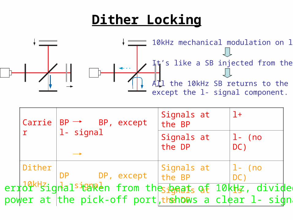
Dither Locking
Carrier BP BP, except l- signalSignals at the BP l+
Signals at the DP l- (no DC)
Dither
10kHzDP DP, except l- signal
Signals at the BP l- (no DC)
Signals at the DP ls
10kHz mechanical modulation on l-
It’s like a SB injected from the DP.
All the 10kHz SB returns to the DPexcept the l- signal component.
The error signal taken from the beat of 10kHz, divided by the power at the pick-off port, shows a clear l- signal.

Locking the PRM-SRM cavity
The PRM follows the swinging SRM
Then, once ls is locked, we’ll recover l+ = 0º.
After locking the l-, the condition is simple.

Successful Locking
l- lock
ls lock l+ lock
DC@AP
DC@SPDDM@SP(demod phase for ls )
Error of Dither
DDM@SP(demod phase for l+ )
33MHz@SP
ls lock at -5.2 secl- lock at -5.3 secl+ lock at -5.6 sec
Lock now: Control later:l- : dither @AP DDM@AP
l+ : 33@SP DDM@SP
ls : DDM@SP DDM@PO

Part II : Mach-Zehnder Noise

Disturbance by sub-sidebands
Original concept Real world
f1-f1 f2-f2
Carrier
f1-f1 f2-f2
Carrier
Port Dem. Freq.
L L l l l s
SP f1 1 -1.4E-8 -1.2E-3 -1.3E-6 -6.2E-6
AP f2 1.2E-7 1 1.4E-5 1.3E-3 6.5E-6
SP f1 f2 7.4 -3.4E-4 1 -3.3E-2 -1.1E-1
AP f1 f2 -5.7E-4 32 7.1E-1 1 7.1E-2
PO f1 f2 3.3 1.7 1.9E-1 -3.5E-2 1
Port Dem. Freq.
L L l l l s
SP f1 1 -3.8E-9 -1.2E-3 -1.3E-6 -2.3E-6
AP f2 -4.8E-9 1 1.2E-8 1.3E-3 -1.7E-8
SP f1 f2 -1.7E-3 -3.0E-4 1 -3.2E-2 -1.0E-1
AP f1 f2 -6.2E-4 1.5E-3 7.5E-1 1 7.1E-2
PO f1 f2 3.6E-3 2.7E-3 4.6E-1 -2.3E-2 1
• Sub-sidebands are produced by two series EOMs.• Beats between carrier and f2 ± f1 disturb the central part.
Sub-sidebands should be removed.
SB of SB(sub-SB)

Mach-Zehnder to eliminate the sub-SBsSeries EOMs
sub-sidebands are generated
EOM2EOM1
Mach-Zehnder interferometerno sub-sidebands
PD
EOM2
EOM1
PZT
PMC trans
To MC
PZT mirrorBS1
BS2
33MHzEOM
166MHzEOM
29MHzEOM
PD
PMC transmitted
to MC
29MHz EOM hasbeen moved to inside the MZ.
But this MZ introduces additional noise on the frequency.

MZ differential motion noise
PC2
Laser
PC1
~
~
f1
f2 Differential Mode
Common Mode
f1 Caf2
Disturbance of orthogonality between the carrier and the SB.
There are three paths via which MZ noise contributes to L-.

Three paths of MZ noise to L-
(1) Direct coupling with contrast defect component
(2) Via frequency stabilization system of the MC
(3) Via frequency stabilization system of the L+
~ This is not a problem with the DC readout scheme.~ Seiji’s calculation says this is not a problem even with RF readout and if the finesse differs for 10%.
~ This can be suppressed by the FSS of L+.
• (1) and (3) are the same problems as RF phase noise of the EOM.
• Freq noise should be calculated to see if (2) and (3) limit the sensitivity.

Frequency noise of detuned RSE
• J.Camp calculated frequency noise for a PR-FPMI.
• J.Mason extended the calculation with the SR cavity.
What we have;
• Radiation pressure effect caused by freq noise sideband.
• Storage time difference will be larger with higher finesse arms.
• RMS cavity fluctuation converts freq noise to amplitude noise and it appears as freq noise because of the detuning.
What we should add;

Calculated frequency noise TF of the 40m
GW Signal >> two peaks
Freq noise around Carrier >> two peaks >> spectrum shows no dips
Freq noise around RF SB >> flat >> spectrum shows two dips

Requirement of freq fluctuation after MC
Goal sensitivity divided by freq noise TF

Frequency stabilization servo ~preliminary
x: laser freq noisey: MC displacement noisez: MZ differential noise
G >> 40m MC servoG’, H’ >> TAMA servo (just for example)

MC sensitivity requirement
This is hopefully not a big problem since the total noise level is limited by PSL noise at high frequencies.

MZ sensitivity requirement
MZ noise will limit the sensitivity at 100~1kHz.

Is there a way to prove the contribution of MZ noise?
• We have seen the offset voltage on the MC error signal when MZ is not locked to the bright fringe.
• We can measure the MZ noise on the reflected light of the MC, although the contribution is less than on the transmitted light.
x: laser freq noise, y: MC motion noise, z: MZ diff noiseF: finesse and LPF of the MC, G: VCO gain, H: MCL gain
>> next page

Comparison of MC noise and MZ noise on the MC reflected light
true only around this region,where FSS gain is high enough
• We are able to measure the TF from MZ noise to MC noise.• We cannot see the direct contribution on the noise spectrum.

How to reduce the MZ noise?
• Installation of a phase-correcting pockels cell in a MZ arm.
• Alternative to the MZ; Virtual Mach-Zehnder [ref. P.Beyersdorf’s document]

Conclusion
• The lock acquisition scheme with the dither locking has been developed and we have succeeded in locking the central part.
• So far the PRC is locked to the carrier, and the next step is to lock the PRC to the sidebands.
• Frequency noise of DRSE has been analytically calculated.
• We have installed the MZ to remove sub-sidebands, but it introduces additional MZ noise via freq noise.
• There are a few ways to reduce the MZ noise and shall be tested in the 40m.