CallPilot 4.0 201i Server Hardware...
178
CallPilot Release 4.0 Document Number: 555-7101-220 Document Version: Standard 1.07 November 2006 201i Server Hardware Installation
Transcript of CallPilot 4.0 201i Server Hardware...

CallPilotRelease 4.0
Document Number: 555-7101-220
Document Version: Standard 1.07
November 2006
201i Server Hardware Installation

Standard 1.07
2 CallPilot
Copyright © 2006 Nortel Networks.
All Rights Reserved.
The information in this document is subject to change without notice. The statements, configurations, technical data, and recommendations in this document are believed to be accurate and reliable, but are presented without express or implied warranty. Users must take full responsibility for their applications of any products specified in this document. The information in this document is proprietary to Nortel Networks.
The process of transmitting data and call messaging between the CallPilot server and the switch or system is proprietary to Nortel Networks. Any other use of the data and the transmission process is a violation of the user license unless specifically authorized in writing by Nortel Networks prior to such use. Violations of the license by alternative usage of any portion of this process or the related hardware constitutes grounds for an immediate termination of the license and Nortel Networks reserves the right to seek all allowable remedies for such breach.
Trademarks
*Nortel Networks, the Nortel Networks logo, the Globemark, and Unified Networks, BNR, CallPilot, DMS, DMS-100, DMS-250, DMS-MTX, DMS-SCP, DPN, Dualmode, Helmsman, IVR, MAP, Meridian, Meridian 1, Meridian Link, Meridian Mail, Norstar, SL-1, SL-100, Succession, Supernode, Symposium, Telesis, and Unity are trademarks of Nortel Networks.
3COM is a trademark of 3Com Corporation.
ADOBE is a trademark of Adobe Systems Incorporated.
ATLAS is a trademark of Quantum Corporation.
BLACKBERRY is a trademark of Research in Motion Limited.

November 2006
201i Server Hardware Installation 3
CRYSTAL REPORTS is a trademark of Seagate Software Inc.
EUDORA and QUALCOMM are trademarks of Qualcomm, Inc.
ETRUST and INOCULATEIT are trademarks of Computer Associates Think Inc.
DIRECTX, EXCHANGE.NET, FRONTPAGE, INTERNET EXPLORER, LINKEXCHANGE, MICROSOFT, MICROSOFT EXCHANGE SERVER, MS-DOS, NETMEETING, OUTLOOK, POWERPOINT, VISUAL STUDIO, WINDOWS, WINDOWS MEDIA, WINDOWS NT, and WINDOWS SERVER are trademarks of Microsoft Corporation.
GROUPWISE and NOVELL are trademarks of Novell Inc.
INTEL is a trademark of Intel Corporation.
LOGITECH is a trademark of Logitech, Inc.
MCAFEE and NETSHIELD are trademarks of McAfee Associates, Inc.
MYLEX is a trademark of Mylex Corporation.
NETSCAPE COMMUNICATOR is a trademark of Netscape Communications Corporation.
NOTES is a trademark of Lotus Development Corporation.
NORTON ANTIVIRUS and PCANYWHERE are trademarks of Symantec Corporation.
QUICKTIME is a trademark of Apple Computer, Inc.
RADISYS is a trademark of Radisys Corporation.
ROLM is a trademark of Siemens ROLM Communications Inc.
SLR4, SLR5, and TANDBERG are trademarks of Tandberg Data ASA.

Standard 1.07
4 CallPilot
SONY is a trademark of Sony Corporation.
SYBASE is a trademark of Sybase, Inc.
TEAC is a trademark of TEAC Corporation.
US ROBOTICS, the US ROBOTICS logo, and SPORTSTER are trademarks of US Robotics.
WINZIP is a trademark of Nico Mark Computing, Inc.
XEON is a trademark of Intel, Inc.
All other trademarks and registered trademarks are the property of their respective owners.
Information for Japan
Japan VCCI statementThe following applies to server models 1005r, 703t, 201i, and 1002rp:
この装置は、情報処理装置等電波障害自主規制協議会 (VCCI) の規定に基づくク
ラス A 装置です。この装 置を家庭環境で使用すると電波妨害を引き起こすことがあります。この場合には使用者が適切な対策を取るように要求されることがあります。
This is a Class A product based on the standard of the Voluntary Control Council for Interference by Information Technology Equipment (VCCI). If this equipment is used in a domestic environment, radio disturbance may occur, in which case, the user may be required to take corrective action.

201i Server Hardware Installation 5
Publication history
November 2006 Standard 1.07 of 201i Server Hardware Installation is released for CallPilot 4.0 general availability.
October 2006 Standard 1.06 of 201i Server Hardware Installation is released for CallPilot 4.0 general availability.
October 2006 Standard 1.05 of 201i Server Hardware Installation is released for CallPilot 4.0 general availability.
September 2006 Standard 1.04 of 201i Server Hardware Installation is up-issued for CallPilot 4.0.
July 2006 Standard 1.03 of 201i Server Hardware Installation is released for CallPilot 4.0 general availability.
April 2006 Standard 1.02 of 201i Server Hardware Installation is released for CallPilot 4.0 general availability.
July 2005 Standard 1.01 of 201i Server Hardware Installation is released for CallPilot 4.0 general availability.
July 2005 Standard 1.0 of 201i Server Hardware Installation is released for CallPilot 4.0 general availability.
November 2004 Standard 1.0 of CallPilot Installation and Configuration, 201i Server Hardware Installation is released for CallPilot 3.0 general availability.
May 2003 Standard 1.0 of CallPilot Installation and Configuration, Part 2: 201i Server Hardware Installation is released for CallPilot 2.02 (2.01.27.05) general availability.

6 CallPilot
Publication history Standard 1.07
September 2002 Standard 1.0 of CallPilot Installation and Configuration, Part 2: 201i Server Hardware Installation is released for CallPilot 2.0 general availability.

November 2006 Publication history
201i Server Hardware Installation 7
.
FundamentalsCallPilot Fundamentals Guide (555-7101-010)
Planning and Engineering
Data Networking for Voice over IP Guide (553-3001-160)Network Planning Guide (555-7101-102)
Installation and Configuration
Installation and Configuration Task List Guide (555-7101-210)Upgrade and Platform Migration Guide (555-7101-207)
Server Installation Guides201i Server Hardware Installation Guide (555-7101-220)703t Server Hardware Installation Guide (555-7101-226)1002rp Server Hardware Installation Guide (555-7101-205)1005r Server Hardware Installation Guide (555-7101-228)
Configuration and Testing GuidesMeridian 1 and CallPilot Server Configuration Guide (555-7101-222)T1/SMDI and CallPilot Server Configuration Guide (555-7101-224)Succession 1000 System and CallPilot Server Configuration Guide (555-7101-510)
Unified Messaging Software InstallationDesktop Messaging and MyCallPilot Installation Guide (555-7101-505)
Administration
Administrator's Guide (555-7101-301)Software Administration and Maintenance Guide (555-7101-202)Desktop Messaging and MyCallPilot Administration Guide (555-7101-503)Meridian Mail to CallPilot Migration Guide (555-7101-801)Application Builder Guide (555-7101-325)Reporter Guide (555-7101-310)
Maintenance
Troubleshooting Guide (555-7101-501)Server Maintenance and Diagnostics
201i Server Maintenance and Diagnostics Guide (555-7101-119)703t Server Maintenance and Diagnostics Guide (555-7101-227)1002rp Server Maintenance and Diagnostics Guide (555-7101-206)1005r Server Maintenance and Diagnostics Guide (555-7101-512)Symposium, M1/Succession 1000, and Voice Processing Guide (297-2183-909)
End User InformationEnd User Cards End User Guides
CallPilot Customer Documentation Map
Unified Messaging Quick Reference CardUnified Messaging Wallet CardA-Style Command Comparison CardS-Style Command Comparison CardMenu Interface Quick Reference CardAlternate Command Interface Quick Reference Card
Multimedia Messaging User GuideSpeech Activated Messaging User GuideDesktop Messaging User Guide for Microsoft OutlookDesktop Messaging User Guide for Lotus NotesDesktop Messaging User Guide for Novell GroupwiseDesktop Messaging User Guide for Internet ClientsMyCallPilot User Guide
Planning and Engineering Guide (555-7101-101)

8 CallPilot
Publication history Standard 1.07

201i Server Hardware Installation 9
Task List
To unpack the 201i server............................................................... 41To prepare the 201i server for installation in a Meridian 1 switch ... 52To position the 201i server on the switch shelf ............................... 56To remove the backplane cables .................................................... 59To install the NTRH3501 backplane cable ...................................... 63To install the SCSI cables for Meridian 1 ........................................ 68To position the 201i server on the switch shelf ............................... 72To install the cable .......................................................................... 81To install the NTRH3502 SCSI cable .............................................. 88To connect the cables ..................................................................... 92To remove the front bezel and inside front cover plate ............ 104To install the 201i server inside the Media Gateway or Media Gateway Expansion ...................................................................... 108To install the NTRH3502 cable ..................................................... 111To replace the inside front cover plate .......................................... 114To replace the front bezel.............................................................. 116To connect the cables ................................................................... 117To install the MPCs ....................................................................... 140To connect the monitor, keyboard, and mouse ............................. 143To connect the CD-ROM and tape drives to the 201i server (Meridian 1) ................................................................................... 145To connect the CD-ROM and tape drives to the 201i server (Option 11C).................................................................................. 147To connect the CD-ROM and tape drives to the 201i server (Option 11C Mini) .......................................................................... 149To connect the CD-ROM and tape drives to the 201i server (Succession 1000)......................................................................... 151To establish the switch and network connections ......................... 153To connect the modem.................................................................. 156To complete the installation and start the 201i server................... 159

Task List Standard 1.07
10 CallPilot
201i Server Hardware Installation 11
Contents
1 How to get help 13
2 About the 201i server 15201i server description . . . . . . . . . . . . . . . . . . . . . . . . . . . . . . . . . . . . . . . . 16Network connectivity . . . . . . . . . . . . . . . . . . . . . . . . . . . . . . . . . . . . . . . . . 24Peripheral connectivity . . . . . . . . . . . . . . . . . . . . . . . . . . . . . . . . . . . . . . . . 31
3 Preparing for installation 35Installation overview. . . . . . . . . . . . . . . . . . . . . . . . . . . . . . . . . . . . . . . . . . 36Unpacking and inspecting the 201i server . . . . . . . . . . . . . . . . . . . . . . . . . 41Switch and network requirements. . . . . . . . . . . . . . . . . . . . . . . . . . . . . . . . 44
4 Installing the 201i server in a large Meridian 1 system 47
Overview. . . . . . . . . . . . . . . . . . . . . . . . . . . . . . . . . . . . . . . . . . . . . . . . . . . 48Repositioning the secondary backplane connector . . . . . . . . . . . . . . . . . . . 50Installing the 201i server in the large Meridian 1 switch . . . . . . . . . . . . . . 56Removing the backplane (tip and ring) cables . . . . . . . . . . . . . . . . . . . . . . 58Installing the NTRH3501 backplane cable . . . . . . . . . . . . . . . . . . . . . . . . . 62Installing the SCSI cables for Meridian 1. . . . . . . . . . . . . . . . . . . . . . . . . . 65
5 Installing the 201i server in an Option 11C or Option 11C Mini 71
Installing the 201i server in the Option 11C or Option 11C Mini switch . 72
Section A: Installing Option 11C cables 77Installing the intermediate SCSI cable for Option 11C . . . . . . . . . . . . . . . 78
Section B: Installing Option 11C Mini cables 85Installing the NTRH3502 SCSI cable for Option 11C Mini . . . . . . . . . . . 86Installing cables on the back of the Option 11C Mini cabinet . . . . . . . . . . 92

Contents Standard 1.07
12 CallPilot
6 Installing the 201i server in the Succession 1000 system 95
Succession 1000 description. . . . . . . . . . . . . . . . . . . . . . . . . . . . . . . . . . . . 96Removing the Media Gateway or Media Gateway Expansion cover . . . . 104Installing the 201i server. . . . . . . . . . . . . . . . . . . . . . . . . . . . . . . . . . . . . . 107Installing the NTRH3502 SCSI cable for Succession 1000 . . . . . . . . . . . 110Replacing the Media Gateway or Media Gateway Expansion cover . . . . 114Connecting cables to the Succession 1000 system . . . . . . . . . . . . . . . . . . 117
7 Preparing peripheral devices 121Overview. . . . . . . . . . . . . . . . . . . . . . . . . . . . . . . . . . . . . . . . . . . . . . . . . . 122Setting the modem DIP switches . . . . . . . . . . . . . . . . . . . . . . . . . . . . . . . 124Setting the CD-ROM drive SCSI ID and DIP switches . . . . . . . . . . . . . . 126Setting the tape drive SCSI ID . . . . . . . . . . . . . . . . . . . . . . . . . . . . . . . . . 128Setting SCSI device termination. . . . . . . . . . . . . . . . . . . . . . . . . . . . . . . . 130
8 Connecting peripheral devices to the 201i server 135Overview. . . . . . . . . . . . . . . . . . . . . . . . . . . . . . . . . . . . . . . . . . . . . . . . . . 136Installing the MPCs . . . . . . . . . . . . . . . . . . . . . . . . . . . . . . . . . . . . . . . . . 140Installing the monitor, keyboard, and mouse . . . . . . . . . . . . . . . . . . . . . . 142Connecting the CD-ROM and tape drives . . . . . . . . . . . . . . . . . . . . . . . . 144Connecting the 201i server to the switch, ELAN, and CLAN . . . . . . . . . 153Connecting the modem . . . . . . . . . . . . . . . . . . . . . . . . . . . . . . . . . . . . . . . 156Completing the installation. . . . . . . . . . . . . . . . . . . . . . . . . . . . . . . . . . . . 159
A RoHS part conversion table 163RoHS part conversion table . . . . . . . . . . . . . . . . . . . . . . . . . . . . . . . . . . . 164
Index 169

201i Server Hardware Installation 13
C h a p t e r 1
How to get help
This section explains how to get help for Nortel products and services.
Getting Help from the Nortel Web site
The best way to get technical support for Nortel products is from the Nortel Technical Support Web site:
http://www.nortel.com/support
This site provides quick access to software, documentation, bulletins, and tools to address issues with Nortel products. More specifically, the site enables you to:
download software, documentation, and product bulletins
search the Technical Support Web site and the Nortel Knowledge Base for answers to technical issues
sign up for automatic notification of new software and documentation for Nortel equipment
open and manage technical support cases
Getting Help over the phone from a Nortel Solutions Center
If you don’t find the information you require on the Nortel Technical Support Web site, and have a Nortel support contract, you can also get help over the phone from a Nortel Solutions Center.
In North America, call 1-800-4NORTEL (1-800-466-7835).

How to get help Standard 1.07
14 CallPilot
Outside North America, go to the following Web site to obtain the phone number for your region:
http://www.nortel.com/callus
Getting Help from a specialist by using an Express Routing Code
To access some Nortel Technical Solutions Centers, you can use an Express Routing Code (ERC) to quickly route your call to a specialist in your Nortel product or service. To locate the ERC for your product or service, go to:
http://www.nortel.com/erc
Getting Help through a Nortel distributor or reseller
If you purchased a service contract for your Nortel product from a distributor or authorized reseller, contact the technical support staff for that distributor or reseller.

201i Server Hardware Installation 15
C h a p t e r 2
About the 201i server
In this chapter201i server description 16
Network connectivity 24
Peripheral connectivity 31

About the 201i server Standard 1.07
16 CallPilot
201i server description
Introduction
The 201i server is a flexible multimedia telephony server designed to integrate with Nortel Meridian 1* and Succession* 1000 products.
The 201i server occupies two slots of a Meridian 1 shelf or Succession 1000 Media Gateway or Media Gateway Expansion. When the server is locked into position, its connectors attach to the backplane, which provides power and communications links.
RoHS compliance
Nortel is phasing in RoHS-compliant 201i servers in countries affected by the EUED (European Union Environmental Directives). This hardware replaces or supplements the non-RoHS version. In general, the RoHS parts are backwards compatible with the supported software, and they have equivalent functionality to the parts they are replacing. RoHS refers to the Reduction of Hazardous Substances Directive.
The text and diagrams in this guide refer to the part numbers for non-RoHS-compliant servers. If you are installing a RoHS-compliant server, see Appendix A, “RoHS part conversion table,” for a listing of each RoHS-compliant part mapped to the equivalent non-RoHS-compliant part.
Primary components
The 201i server motherboard houses the interfaces needed:
to communicate with the Meridian 1 switch or Succession 1000 system
to facilitate data communications on Ethernet networks.

November 2006 About the 201i server
201i Server Hardware Installation 17
Two Ethernet controllers on the 201i server motherboard provide Ethernet capability. These controllers provide the network interfaces for both the embedded LAN (ELAN) and customer LAN (CLAN). The connections to the ELAN and CLAN are established by using the multi I/O cable described on page 28.
Note: The secondary backplane connector connects the 201i server to the second slot on the shelf, thereby providing access to the voice channels provided by that slot.
ATTENTION The 201i server is shipped ready for installation into an Option 11C or Option 11C Mini switch or Succession 1000 system. Before you install the 201i server in a larger Meridian 1 switch (for example, Option 51C), you must move the secondary backplane (DS30X) connector to the correct position. For more information, see “Repositioning the secondary backplane connector” on page 50.

About the 201i server Standard 1.07
18 CallPilot
The following diagram shows the 201i server components:.
Heat sink
Hard drive power cable
Hard drive data cable
Secondary backplane connector pin
Secondary backplane connector
3.5-inch IDE hard drive
Hard drive mounting bracket
Software feature key(Dongle)
Faceplate
Monitor connector
Mouse connector
Keyboard connector

November 2006 About the 201i server
201i Server Hardware Installation 19
Faceplate
The following diagram shows the 201i server faceplate. The faceplate provides LEDs, MPC card slots, and connectors for peripheral devices:
G101438
Lock latch
Keyboard connector
Mouse connector
Infrared port (future use)
Monitor connector
Power status LED
MPC status LEDs
MPC ejector buttons(slots 4 and 5)
MPC ejector buttons(slots 2 and 3)
MPC slots 4 and 5
MPC slots 2 and 3
HEX display
MPC status LEDs
Network and drive activity LEDs
SCSI connector
Lock latch
Reset button

About the 201i server Standard 1.07
20 CallPilot
The following table describes each faceplate feature:
Faceplate feature Description
Mouse connector The mouse connector is a standard PS/2 connector and is hot-pluggable.
Lock latches Lock latches at the top and bottom of the faceplate secure the server to the backplane of the Meridian 1 switch or the backplane of the Succession 1000 Media Gateway or Media Gateway Expansion.
Keyboard connector The keyboard connector is a standard PS/2 connector and is hot-pluggable.
Infrared port For future use.
Monitor connector The monitor connector is a standard, high-density, 15-pin female connector.
Power status LED The LED indicates two server states:
the completion of self-test diagnostics
when it is safe to remove the server from the Meridian 1 switch or Succession 1000 Media Gateway or Media Gateway Expansion
MPC card status LEDs
There is an LED for each MPC card slot. The following list describes each LED status:
Off: The MPC card is not receiving power. It is safe to remove the card.
On: The MPC card is in use. It is not safe to remove the card.
Off, then on: The MPC card has been recognized by the 201i server software and has been powered up.

November 2006 About the 201i server
201i Server Hardware Installation 21
MPC card status LEDs (continued)
On, then off: The MPC card has been successfully powered down. It is safe to remove the card.
Note: For instructions on powering up or powering down the MPC card, see “Starting and stopping components” in the CallPilot 201i Server Maintenance and Diagnostics guide.
MPC card ejector buttons
There is one ejector button for each MPC card slot. When you insert the card, the associated ejector button pops out.
Press the button to eject the card from its slot.
MPC card slots MPCs house DSP units and are used for multimedia telephony processing. You can install up to four MPCs on the 201i server. The 201i is shipped with two MPC-8 cards installed. All slots are faceplate-accessible.
The MPCs are numbered as follows:
top row of slots: MPC cards 4 and 5
bottom row of slots: MPC cards 2 and 3
Note: MPC 1 is embedded on the motherboard.
Hexadecimal (HEX) display
The four-digit LED-based display provides feedback on the current status of the server, including fault conditions.
SCSI connector This connector connects SCSI devices to the 201i server (for example, a CD-ROM or tape drive).
Press the button latches to lock or unlock a cable from the connector.
Faceplate feature Description

About the 201i server Standard 1.07
22 CallPilot
Environmental specifications
Temperatures
Relative humidity
Network and drive activity LEDs (labeled as E, C, I, and S)
The E and C LEDs indicate the presence of network activity for both the ELAN and CLAN interfaces (respectively). When they are lit, they indicate that the interfaces are properly attached to their respective hubs. When the LEDs are blinking, there is network activity.
When the I and S LEDs are lit, it means that the IDE hard drive and SCSI device are being accessed.
Reset button The reset hardware was designed for Windows NT and does not function properly in Windows 2003. Do not use this button.
Recommended temperature
15°C (59°F) to 30°C (86°F)
Absolute temperature 10°C (50°F) to 45°C (113°F)
Long-term storage temperature
–20°C (-4°F) to 60°C (140°F)
Short-term storage temperature
–40°C (-40°F) to 70°C (158°F) (less than 72 hours)
Change rate temperature Less than 1°C (34°F) per 3 minutes
Recommended relative humidity (RH)
20% to 55% RH (noncondensing)
Faceplate feature Description

November 2006 About the 201i server
201i Server Hardware Installation 23
Absolute RH 20% to 80% RH (noncondensing)
Long-term storage RH 5% to 95% RH [at –40°C (-40°F) to 70°C (158°F) respectively] (noncondensing)

About the 201i server Standard 1.07
24 CallPilot
Network connectivity
Introduction
This section shows how CallPilot and the Meridian 1 or Succession 1000 system are integrated into your network. It also describes what is required in the network for correct CallPilot operation.
Sample network setup: Meridian 1 switch
The following diagram shows how the 201i server is integrated into your network with the following Meridian 1 switches:
large systems, such as Option 51C
Option 11C
Option 11C Mini
ATTENTION To secure the CallPilot server from unauthorized access, ensure that the CallPilot network is inside your organization’s firewall.

November 2006 About the 201i server
201i Server Hardware Installation 25
G101631
Telephony LAN/Customer LAN (10/100BaseT or 100BaseT)
Web-enabled administrative PC
Web-enabled administrative PC
Desktop client PC
Desktop client PC
Switch
201iCallPilotserver
Modem
Laptop
Router orEthernet switch(optional)
Embedded LAN (10BaseT)

About the 201i server Standard 1.07
26 CallPilot
Sample network setup: Succession 1000
The following diagram shows an example of how the 201i server can be integrated with the Succession 1000 system in your network:
G101630
OptivityTelephony Manager PC
Web-enabledCallPilot administrative PC
Web-enabledCallPilot administrative PC
Desktop client PC
i2004 Internetphonesets
Succession 1000Call Server
Modem
Laptop
Router orEthernet switch(optional)
CE-MUXDS-30x
Succession 1000 Media Gateway Expansion
Embedded LAN (10BaseT)
InternetTelephonyGatewayLine Card
Succession 1000Media Gateway 201i
CallPilotServer
InternetTelephonyGatewayLine Card
Telephony LAN/Customer LAN (10/100BaseT or 100BaseT)

November 2006 About the 201i server
201i Server Hardware Installation 27
In the illustration on page 26, the telephony LAN (TLAN) provides IP connectivity between the Succession 1000 system and the i2004 Internet phonesets. The connection between the Call Server and Media Gateway can be point-to-point, or it can be through the LAN, if the system is installed in a distributed data network.
For information about the Succession 1000 system and i2004 Internet phoneset bandwidth and network requirements, refer to the Succession 1000 Planning and Installation Guide (NTP 553-3023-210).
For a description of each Succession 1000 system component, see “Succession 1000 description” on page 96.
CallPilot CLAN and ELAN network setup
The 201i server supports the following network protocols:
CLAN: 10/100Base-T Ethernet
A built-in Ethernet controller on the 201i server motherboard provides Ethernet CLAN capability. The CLAN provides data connectivity between desktop and web messaging clients, administrative PCs, and the CallPilot server.
ELAN: 10Base-T Ethernet
A built-in Ethernet controller on the 201i server motherboard provides Ethernet ELAN capability. The ELAN carries call processing traffic between the CallPilot server and the Meridian 1 switch or Succession 1000 system.
Note: For more information about the ELAN, see “About the ELAN” in the CallPilot Installation and Configuration Task List.
You use the 201i server multi I/O cable to establish the CLAN and ELAN connections. For more information, see page 28.

About the 201i server Standard 1.07
28 CallPilot
Network requirementsAppropriate networking equipment must be available for both the CLAN and ELAN.
The CLAN and ELAN must be properly configured for correct CallPilot operation. To ensure correct configuration, Nortel recommends that you consult a network specialist.
Multi I/O cable description
The multi I/O cable contains four connectors, and is approximately 3 m (10 ft) in length. See the following diagram:
ATTENTION For important considerations about using the ELAN in your network, see “About the ELAN” in the CallPilot Installation and Configuration Task List.
G101441
RS-232connector
RJ-45 female-to-female gender change jack
Note: If you need more than 3 m (10 ft) of multi I/O cable, use the supplied RJ-45 female-to-female gender change jacks to attach additional cable. A maximum of76.2 m (250 ft) is supported.
ELANconnector
CLANconnector
Drain wire
50-pinamphenolconnector
Multi I/O cable NTRH0912

November 2006 About the 201i server
201i Server Hardware Installation 29
The following table identifies the purpose of each connector on the NTRH09121 multi I/O cable.
Note: Labels on the RJ-45 cables distinguish the CLAN and ELAN connectors.
1.For customers in EUED countries: see Appendix A, “RoHS part conversion table,” to look up part numbers for RoHS-compliant parts that are equivalent to the non-RoHS-compliant parts described in this guide.
Connector type Purpose
50-pin amphenol This connector establishes the connection between the Meridian 1 or Succession 1000 Media Gateway or Media Gateway Expansion backplane and the ELAN hub, the CLAN hub, and the modem.
10Base-T (RJ-45)
This connector provides a 10 Mbit/s Ethernet connection between the 201i server and the Meridian 1 switch or Succession 1000 system. This connection allows the exchange of call control information between the server and the Meridian 1 switch or Succession 1000 system.
For more information about the ELAN, see “About the ELAN” in the CallPilot Installation and Configuration Task List.
10/100Base-T (RJ-45)
This connector provides a network connection for
user desktop computers, to enable use of the unified messaging and fax messaging features
LAN-based server administration
ATTENTION
If you need Ethernet 100Base-T operation at 100 Mbit/s on large Meridian 1 systems (such as Option 51), you must install the NTRH3501 backplane (tip and ring) cable. For more information, see Chapter 4, “Installing the 201i server in a large Meridian 1 system.”

About the 201i server Standard 1.07
30 CallPilot
RS-232 COM1 (male DB-9)
This connector provides the connection to an external modem. The modem allows administrators and technical support personnel to administer the 201i server from a remote location.
Connector type Purpose

November 2006 About the 201i server
201i Server Hardware Installation 31
Peripheral connectivity
Introduction
Peripheral equipment is attached to the 201i server on the server faceplate.
Faceplate connections
The following peripheral devices connect to the 201i server faceplate:
monitor (SVGA)
keyboard
mouse
MPC card (permanent connection)
SCSI cable (permanent connection)
Monitor, keyboard, and mouseYou must connect a monitor, keyboard, and mouse to run the Configuration Wizard or to install the operating system on the 201i server as part of a recovery process.
All three peripheral components are hot-pluggable.
ATTENTION Connections made to the faceplate (with the exceptions noted below) are temporary only, because you must remove the cabinet cover to make these connections. The system does not meet specifications for radiated EMI if you remove the cabinet cover.

About the 201i server Standard 1.07
32 CallPilot
MPC-8 cardThe MPC-8 card looks like a Type II PC card, and supports the multimedia telephony services on the 201i server. Four specially-designed card slots are available for the MPC-8. All are located on the 201i server faceplate.
SCSI connectionsThe SCSI connection is the only permanent faceplate connection. A low-profile right-angle connector on the SCSI cable allows the cable to be attached with the cabinet covers on. For more information about how the 201i server and SCSI device connections are achieved, see:
large Meridian 1 systems (for example, Option 51C): “Installing the SCSI cables for Meridian 1” on page 65.
Option 11C or Option 11C Mini: “Installing the NTRH3502 SCSI cable for Option 11C Mini” on page 86.
Succession 1000: “Installing the NTRH3502 SCSI cable for Succession 1000” on page 110.
Supported peripheral devices
CD-ROM drive (NTRH9105)An external CD-ROM drive is used to install and upgrade the server. The drive connects to the server with an intermediate SCSI cable that connects to the SCSI connector on the faceplate.
Because the CD-ROM drive is an external device, it requires an AC power source.
Set the SCSI ID for the CD-ROM drive to 3. If you are connecting more than one SCSI device to the server (such as a tape drive), you must daisy chain those devices.
ATTENTION You cannot insert MPC-8 cards in Type II PC card slots, or Type II PC cards into MPC-8 card slots. They are not compatible.

November 2006 About the 201i server
201i Server Hardware Installation 33
Note: The CD-ROM drive is not hot-pluggable. You must power off the server to connect or disconnect the drive.
Tape drive (NTRH9038)An external SCSI tape drive is used to back up and restore data. The device connects to the server by an intermediate SCSI cable that connects to the SCSI connector on the faceplate.
Since the tape drive is an external device, it requires an AC power source.
Set the SCSI ID for the tape drive to 5. If you are connecting more than one SCSI device to the server (such as a CD-ROM drive), you must daisy chain those devices.
Note: The tape drive is not hot-pluggable. You must power off the server to connect or disconnect the drive.
ModemAn external modem provides remote access to the 201i server. The modem connects to the RS-232 COM1 connector on the multi I/O cable.
Since the modem is an external device, it requires its own AC power source.
The supported modem is the 56 Kbps modem (NTRH9078).
10Base-T Ethernet hubThe 10Base-T Ethernet hub provides the ELAN connection between the 201i server and the Meridian 1 switch or Succession 1000 system.
Since the hub is an external device, it requires an AC power source.
Monitor, keyboard, and mouse 15 in. monitor: NTRH9011 or N0038380 LCD monitor
Since the monitor is an external device, it requires an AC power source.
Keyboard: NTRH9013
Mouse: NTRH9014

About the 201i server Standard 1.07
34 CallPilot
Note: The mouse connector on the 201i faceplate is a PS/2 connector. If you plan to use a USB mouse with USB-to-PS/2 converter, you must also use the Nortel-supplied 101 mm (4-in) PS/2 extension cable (A0855616). Without the extension cable, the monitor connector partially blocks the mouse connector.

201i Server Hardware Installation 35
C h a p t e r 3
Preparing for installation
In this chapterInstallation overview 36
Unpacking and inspecting the 201i server 41
Switch and network requirements 44

Preparing for installation Standard 1.07
36 CallPilot
Installation overview
Introduction
This section provides a high-level overview of the requirements and procedure for installing the 201i server.
For a list of CallPilot documentation, see the document map on page 7.
Before you begin
Ensure that proper power and grounding are available for all the power outlets serving the CallPilot server and its associated peripherals. Power for these devices must be wired and fused independently of all other receptacles and referenced to the same ground as the PBX system.
A qualified electrician must implement the single-point ground reference as required between the power outlets of the CallPilot server and the power outlets of the switch.
Provide a sufficient number of properly grounded power outlets or power bars for all equipment.
For more information, refer to Chapter 2, “Grounding and power requirements”, in the CallPilot Planning and Engineering Guide.

November 2006 Preparing for installation
201i Server Hardware Installation 37
Installation checklist
The following checklist identifies the steps required to install the 201i server and peripheral devices. For more details, see Chapter 8, “Connecting peripheral devices to the 201i server.”
.
WARNING
Risk of personal injury and hardware failureThe power outlets used by the CallPilot server and its peripheral devices must be connected to the same ground reference as the one used by the Meridian 1 switch or Succession 1000 system with MGate cards (NTRB18CA) connected to the CallPilot server. If this requirement is not met, power transients can cause personal injury and hardware failure.
Step Description Check
1 Ensure that you have reviewed the “Installing CallPilot” section in the CallPilot Installation and Configuration Task List and completed stage 1 of the “Installation checklist.”
This includes the following tasks:
❒
Unpack the server, and ensure you have all the items you need (see page 41).
Complete the following checklists that are provided in the CallPilot Installation and Configuration Task List:
— “CallPilot software media and documentation checklist”
— “CallPilot server hardware checklist”
❒
Inspect the server for any damage that might have occurred during shipping (see page 41).
❒

Preparing for installation Standard 1.07
38 CallPilot
2 Familiarize yourself with the “Switch and network requirements” on page 44 of this guide.
❒
3 If you are installing the 201i server into a Meridian 1 tiered system, do the following:
Change the location of the secondary backplane (DS30X) connector on the 201i server (see page 50).
Replace the existing backplane (tip and ring) cable on the Meridian 1 with the one supplied with the 201i server (NTRH3501) (see pages 58–64).
❒
4 Install the intermediate SCSI cable. This cable connects the external CD-ROM or tape drive.
For Meridian 1, you require two cables to complete the connection between the 201i server and the SCSI device: NTRH1408 and NTRH1410. See page 65.
For Option 11C, you require two cables to complete the connection between the 201i server and the SCSI device: NTRH1407 and NTRH3502. See page 78.
For Option 11C Mini or Succession 1000, you require one cable to complete the connection between the 201i server and the SCSI device: the NTRH3502 cable that is provided in the CD-ROM and tape drive kits. See the following:
— Option 11C Mini: page 86
— Succession 1000: page 110
❒
5 Set the DIP switches on the modem (see page 124). ❒
Step Description Check

November 2006 Preparing for installation
201i Server Hardware Installation 39
6 Set the following:
SCSI IDs on the CD-ROM and tape drives (see pages 126 and 128)
DIP switches on the CD-ROM drive (see page 126)
device termination on the CD-ROM and tape drives (see page 130)
❒
7 Insert the 201i server into two consecutive slots inside the switch. For instructions, see:
large Meridian 1 systems, such as Option 51C (see page 56)
Option 11C or Option 11C Mini (see page 72)
Succession 1000 (see page 107)
❒
8 Install the MPC cards, if required (see page 140). ❒
Step Description Check

Preparing for installation Standard 1.07
40 CallPilot
9 Connect the 201i server and devices as follows:
Connect the monitor, keyboard, and mouse to the 201i server faceplate (see page 142).
❒
Connect the CD-ROM and tape drives to the intermediate SCSI cable (see page 144).
❒
Connect the multi I/O cable to the ELAN and CLAN network hubs (see page 153).
Note: If more than 3 m (10 ft) of multi I/O cable is required, use the supplied RJ-45 female-to-female gender change jacks to attach additional cable. Up to 76.2 m (250 ft) of cable length is supported.
❒
Connect the modem to the multi I/O cable (maximum length 15 m (50 ft) (see page 156).
❒
Connect the power cords for all devices, and then power them up.
❒
10 Complete the installation of the 201i server as follows:
Connect the intermediate SCSI cable to the 201i server faceplate.
Close the lock latches on the 201i server.
Boot the 201i server to the operating system.
See page 159.
❒
11 Continue with the CallPilot <switch model> and CallPilot Server Configuration guide for your switch and server.
❒
Step Description Check

November 2006 Preparing for installation
201i Server Hardware Installation 41
Unpacking and inspecting the 201i server
Introduction
This section describes how to:
unpack the 201i server and peripherals
inspect the 201i server for damage
It also describes what to do if you determine that the 201i server is faulty.
To unpack the 201i server
1 Remove the 201i server from the carton and its antistatic bag.
2 Place the 201i server on an antistatic surface.
3 Carefully open the cartons containing the monitor, keyboard, mouse, modem, and ELAN hub (if supplied), and set the peripherals aside.
4 Put all manuals and CD-ROMs in a safe place.
5 Save all packing materials and cartons in case you must return any equipment to the carrier.
6 Review “201i server description” on page 16, and perform a visual inspection as described in “To inspect the 201i server for shipping damage” on page 42.
ATTENTION As you unpack each item, check it off against the packing list, as well as the following checklists provided in the CallPilot Installation and Configuration Task List:
“CallPilot software media and documentation checklist”
“CallPilot server hardware checklist”

Preparing for installation Standard 1.07
42 CallPilot
To inspect the 201i server for shipping damage
Before proceeding with the installation, visually inspect the 201i server for any damage that might have occurred during shipping. Ensure also that the items in the following checklists are secure:
What to do if components are missing or damaged
Item Yes No
Are all cables securely seated?
hard drive power cable
hard drive data cable
See items 2 and 3 in the diagram on page 18.
❒
❒
❒
❒
Is the hard drive and bracket interface secure? See items 6 and 7 in the diagram on page 18.
❒ ❒
Is the software feature key (dongle) securely seated in its bracket?
See 201i server components diagram on page 18.
❒ ❒
IF THEN
you observe any damage
contact your Nortel technical support representative.
components have become loose
secure them.
If necessary, refer to the procedures in the CallPilot <server model> Server Maintenance and Diagnostics guide for your server.
you are satisfied that the 201i server has arrived at your site undamaged
you are ready to proceed with installation.

November 2006 Preparing for installation
201i Server Hardware Installation 43
What’s next?
Review the “Switch and network requirements” on page 44.

Preparing for installation Standard 1.07
44 CallPilot
Switch and network requirements
Introduction
The information in this section will help you plan your 201i server installation.
Meridian 1 or Succession 1000 slot requirements
The 201i server occupies two physical and electrical slots.
You must install the 201i server in two peripheral equipment slots as follows:
Switch Slots
Meridian 1 tieredsystems
0 through 14
Ensure that both slots have electrical backplane connectivity.
Option 11C 1 through 9 in any Option 11C cabinet
Note: Both of the server backplane connectors must be installed in slots 1 through 9 to receive proper power. Neither connector can reside in slot 10.
Option 11C Mini A pair of consecutive slots in any cabinet
Note: You cannot install the 201i server in slots 0 or 4 because these slots are dedicated to other cards. For more information about cards and slots, refer to the Option 11C Mini documentation.

November 2006 Preparing for installation
201i Server Hardware Installation 45
Meridian 1 I/O panel connections
On large Meridian 1 systems (such as Option 51C), the 201i server requires two connections from the slots to the I/O panel on the rear of the switch, as follows:
One connection is for the multi I/O cable.
This connection corresponds to the left slot (when viewing the front of the Meridian 1 switch).
The other connection is for the external SCSI device.
This connection corresponds to the right slot (when viewing the front of the Meridian 1 switch).
For information about slot and rear bulkhead wiring, refer to the Meridian 1 System Installation and Maintenance Guide (NTP 553-3001-210).
CLAN and ELAN network requirements
If you have a LAN (for example, customer LAN [CLAN] or embedded LAN [ELAN]), the LAN must be configured and the appropriate networking equipment must be available.
Succession 1000 A pair of consecutive slots in any Media Gateway or Media Gateway Expansion.
Note: The 201i server cannot be installed in slots 0 or 4, because these slots are dedicated to other cards. For more information about cards and slots, refer to the Succession 1000 Planning and Installation Guide (NTP 553-3023-210).
Switch Slots

Preparing for installation Standard 1.07
46 CallPilot
If the LAN is to be networked with the 201i server, you need a network specialist to ensure proper configuration.
What’s next?
Install the 201i server in the Meridian 1 switch or Succession 1000 system. For instructions, see one of the following:
ATTENTION For important considerations about using the ELAN in your network, see “About the ELAN” in the CallPilot Installation and Configuration Task List.
To install the 201i server in See
a large Meridian 1 switch (for example, Option 51C)
Chapter 4, “Installing the 201i server in a large Meridian 1 system.”
an Option 11C or Option 11C Mini switch
Chapter 5, “Installing the 201i server in an Option 11C or Option 11C Mini.”
the Succession 1000 system Chapter 6, “Installing the 201i server in the Succession 1000 system.”

201i Server Hardware Installation 47
C h a p t e r 4
Installing the 201i server in a large Meridian 1 system
In this chapterOverview 48
Repositioning the secondary backplane connector 50
Installing the 201i server in the large Meridian 1 switch 56
Removing the backplane (tip and ring) cables 58
Installing the NTRH3501 backplane cable 62
Installing the SCSI cables for Meridian 1 65

Installing the 201i server in a large Meridian 1 system Standard 1.07
48 CallPilot
Overview
Introduction
This section describes how to install the 201i server in a Meridian 1 switch.
Meridian 1 I/O panel connections
On the Meridian 1, the 201i server requires two connections from the slots to the I/O panel on the rear of the switch, as follows:
One connection is for the multi I/O cable.
This connection corresponds to the left slot (when viewing the front of the Meridian 1 switch).
The other connection is for the external SCSI device.
This connection corresponds to the right slot (when viewing the front of the Meridian 1 switch).
For information about slot and rear bulkhead wiring, refer to the Meridian 1 System Installation and Maintenance Guide (NTP 553-3001-210).
Secondary backplane connector
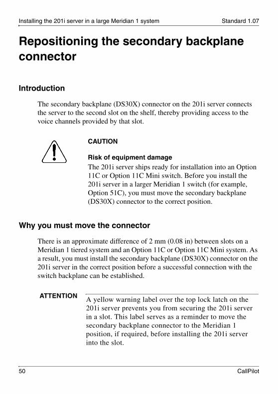
The secondary backplane (DS30X) connector on the 201i server connects the server to the second slot on the shelf, thereby providing access to the voice channels provided by that slot.
ATTENTION To install the 201i server in an Option 11C, go to page 72. For Option 11C Mini, go to page 85. For Succession 1000, go to page 95.

November 2006 Installing the 201i server in a large Meridian 1 system
201i Server Hardware Installation 49
Backplane (tip and ring) cable
The backplane (tip and ring) cable supplied with the 201i server (NTRH3501) provides 100Base-T Ethernet CLAN operation. This cable offers more network throughput than the cable that is already installed on the Meridian 1.
When installed, this cable completes the connection between the left slot, the I/O panel on the rear of the switch, and the multi I/O cable on the 201i server.
SCSI cables
Before you can connect a CD-ROM or tape drive to the 201i server, you must install the SCSI cables. You require two cables. These cables route the SCSI connection away from the 201i server faceplate so that an external SCSI device can remain permanently connected.
.
CAUTION
Risk of equipment damageThe 201i server is shipped ready for installation into an Option 11C switch. Before you install the 201i server in a larger Meridian 1 switch (for example, Option 51C), you must move the secondary backplane (DS30X) connector to the correct position.
ATTENTION A yellow warning label over the top lock latch on the 201i server prevents you from securing the 201i server in a slot. This label serves as a reminder to move the secondary backplane connector to the Meridian 1 position, if required, before installing the 201i server into the slot.
Installing the 201i server in a large Meridian 1 system Standard 1.07
50 CallPilot
Repositioning the secondary backplane connector
Introduction
The secondary backplane (DS30X) connector on the 201i server connects the server to the second slot on the shelf, thereby providing access to the voice channels provided by that slot.
Why you must move the connector
There is an approximate difference of 2 mm (0.08 in) between slots on a Meridian 1 tiered system and an Option 11C or Option 11C Mini system. As a result, you must install the secondary backplane (DS30X) connector on the 201i server in the correct position before a successful connection with the switch backplane can be established.
.
CAUTION
Risk of equipment damageThe 201i server ships ready for installation into an Option 11C or Option 11C Mini switch. Before you install the 201i server in a larger Meridian 1 switch (for example, Option 51C), you must move the secondary backplane (DS30X) connector to the correct position.
ATTENTION A yellow warning label over the top lock latch on the 201i server prevents you from securing the 201i server in a slot. This label serves as a reminder to move the secondary backplane connector to the Meridian 1 position, if required, before installing the 201i server into the slot.

November 2006 Installing the 201i server in a large Meridian 1 system
201i Server Hardware Installation 51
Secondary backplane connector description
The secondary backplane connector is attached to the backplane edge of the 201i server. It consists of the following items:
connector
screws
pin connector (with four pins)
Two pairs of screw holes are provided for connecting the secondary backplane connector to the 201i server stiffening cage. The outside pair provides the Meridian 1 spacing. The inside pair provides the Option 11C or Option 11C Mini spacing.
See the following diagram:
G101443
Stiffening cage
Screw location for Option 11C
Connectorpin socket
Screw location for Option 11C
Screw location for Meridian 1
Screw location for Meridian 1
Secondarybackplaneconnector
Secondarybackplaneconnector front view

Installing the 201i server in a large Meridian 1 system Standard 1.07
52 CallPilot
Required equipment
To move the secondary backplane connector, you need a Phillips No. 1 screwdriver. A pair of needle-nosed pliers can also be helpful for removing the pin connector.
To prepare the 201i server for installation in a Meridian 1 switch
1 Remove the secondary backplane pin connector.
The pin connector has four pins. If necessary, use needle-nosed pliers to remove it.
2 Remove the top and bottom screws that hold the secondary backplane connector in place on the stiffening cage.
3 Loosen the middle screw, and then align the outside pair of screw holes on the bracket with the matching pair on the stiffening cage.
4 Replace and alternately tighten all screws until the connector is evenly and securely fastened.

November 2006 Installing the 201i server in a large Meridian 1 system
201i Server Hardware Installation 53
See the following diagram:
5 Replace the pin connector so the pins protrude through both connectors.
Ensure that the connectors are correctly aligned as shown in the diagram below.
.
CAUTION
Risk of equipment damage
If the connectors are not correctly aligned when the pin connector is pressed into the socket, the pins can bend.
G101545
Screw locationfor Meridian 1

Installing the 201i server in a large Meridian 1 system Standard 1.07
54 CallPilot
G101442
A
B

November 2006 Installing the 201i server in a large Meridian 1 system
201i Server Hardware Installation 55
6 Gently press the pin connector into the socket until it is fully seated.
7 Remove the yellow backplane warning label from the top lock latch on the 201i server.
What’s next?
Continue with “Installing the 201i server in the large Meridian 1 switch” on page 56.

Installing the 201i server in a large Meridian 1 system Standard 1.07
56 CallPilot
Installing the 201i server in the large Meridian 1 switch
Introduction
The 201i server occupies two slots. You can install the 201i server in slots 0 through 14. Ensure that both slots have electrical backplane connectivity.
To position the 201i server on the switch shelf
1 Ensure that no cables are connected to the slots in which you are installing the 201i server.
2 Open the lock latches at the top and bottom of the 201i server faceplate.
Note: When you open the top lock latch, you break the yellow backplane warning label, if it has not been removed. You must move the secondary backplane connector before you install the 201i server. For details, see “Repositioning the secondary backplane connector” on page 50.
3 Slide the 201i server into an unoccupied pair of slots.
Ensure that the 201i server is positioned correctly between the slots.
4 Connect the low-profile right-angle SCSI cable connector to the SCSI connector on the 201i server faceplate.
ATTENTION Do not push the 201i server into place against the backplane until you are ready to observe the startup cycle.
The 201i server receives power and starts as soon as the 201i server makes contact with the switch backplane.

November 2006 Installing the 201i server in a large Meridian 1 system
201i Server Hardware Installation 57
What’s next?
Continue with “Removing the backplane (tip and ring) cables” on page 58.
Installing the 201i server in a large Meridian 1 system Standard 1.07
58 CallPilot
Removing the backplane (tip and ring) cables
Introduction
You must remove the Meridian 1 backplane (tip and ring) cables that are associated with the slots occupied by the 201i server so that you can install the following cables:
NTRH3501 backplane (tip and ring) cable
The NTRH3501 cable offers more network throughput than the cable that is already installed on the Meridian 1. This cable is connected to the backplane connectors and I/O panel slot associated with the left slot.
NTRH1408 intermediate SCSI cable
The NTRH1408 intermediate SCSI cable routes the SCSI device connection away from the 201i server faceplate so that an external SCSI device can remain permanently connected. This cable is connected to the I/O panel only. The backplane connectors associated with the right slot are left vacant.
These cables are supplied with the 201i server.
Before you begin
Note: For information about slot and rear bulkhead wiring and powering off the shelf, refer to the Meridian 1 System Installation and Maintenance Guide (NTP 553-3001-210).
.
DANGER
Risk of electrical shockEnsure that the shelf is powered off before you remove the backplane cables.

November 2006 Installing the 201i server in a large Meridian 1 system
201i Server Hardware Installation 59
To remove the backplane cables
1 Remove the I/O panel cover from the rear of the Meridian 1 switch.
2 Remove the protective plate from the rear of the Meridian 1 switch.
3 Remove the existing backplane cable, including the I/O filter assembly (NT8D81xx) and mounting hardware for the left slot as follows:
a. Remove the external cable attached to the outside of the I/O panel.
b. For each of the UP 1, UP 2, and UP 3 cable connectors, push the lock tab outwards to unlock the cable connection, and then pull the connector off.
G101547

Installing the 201i server in a large Meridian 1 system Standard 1.07
60 CallPilot
Remove the tie wraps where applicable to free the cable.
c. Remove the connector, I/O filter assembly, and all mounting hardware from the inside of the I/O panel so the slot is completely vacated.
Retain the mounting hardware (that is, screws, tie wrap base, standoffs, and so on). You will reuse this hardware to fasten the NTRH3501 cable.
4 Repeat step 3 to remove the existing backplane cable for the right slot.
Store the cable, I/O filter assembly, and mounting hardware for this cable with your Meridian 1 spares. You will not use them with the 201i server.
ATTENTION If you attempt to pull the connector off without pressing the lock tab, you can pull the connector shroud off the backplane. If this happens, refer to the adjacent connectors for correct key positioning, and then replace the connector shroud.

November 2006 Installing the 201i server in a large Meridian 1 system
201i Server Hardware Installation 61
The following diagram shows an example using slots 3 and 4:
What’s next?
Continue with “Installing the NTRH3501 backplane cable” on page 62.
G101549
C
B
A

Installing the 201i server in a large Meridian 1 system Standard 1.07
62 CallPilot
Installing the NTRH3501 backplane cable
Introduction
You must connect the backplane (tip and ring) cable supplied with the 201i server (NTRH3501) for 100Base-T Ethernet CLAN operation. This cable offers more network throughput than the cable you just removed from the Meridian 1.
When installed, this cable completes the connection between the left slot, the I/O panel on the rear of the switch, and the multi I/O cable on the 201i server.
Backplane (tip and ring) cable
The following diagram shows the NTRH3501 backplane (tip and ring) cable:
G101546
Backplane (tip and ring) cable NTRH3501
UP 1
UP 2
UP 3

November 2006 Installing the 201i server in a large Meridian 1 system
201i Server Hardware Installation 63
Before you begin
Before you can install the NTRH3501 cable, you must remove the existing backplane cable from the back of the switch. See “Removing the backplane (tip and ring) cables” on page 58.
To install the NTRH3501 backplane cable
1 Install and connect the NTRH3501 cable to the multi I/O cable as follows:
a. Attach the backplane connector of the NTRH3501 cable to the inside of the I/O panel slot associated with the 201i server left slot.
Insert the original screw into the tie wrap base and fasten the screw into the lower position of the I/O panel slot.
b. Attach the three inner cables to the backplane connectors associated with the left slot as follows:
— UP 1 cable to the top position
— UP 2 cable to the middle position
— UP 3 cable to the lower position
Use tie wraps to secure the cables in their original positions.
c. Connect the 50-pin amphenol connector on the multi I/O cable (NTRH0912) to the NTRH3501 backplane cable connector on the I/O panel.
ATTENTION The connectors are keyed; you can insert them in one position only.

Installing the 201i server in a large Meridian 1 system Standard 1.07
64 CallPilot
See the following diagram:
What’s next?
Continue with “Installing the SCSI cables for Meridian 1” on page 65.
G101550
Backplane cableNTRH3501
Multi I/O cableNTRH0912
UP 1
UP 2
UP 3
A
BC

November 2006 Installing the 201i server in a large Meridian 1 system
201i Server Hardware Installation 65
Installing the SCSI cables for Meridian 1
Introduction
Before you can connect a CD-ROM or tape drive to the 201i server, you must install the SCSI cables. The SCSI cables route the SCSI connection away from the 201i server faceplate so that an external SCSI device can remain permanently connected.
Cables you need
You require the following cables:
NTRH1408 (for connecting the 201i server to the Meridian 1 I/O panel)
.
CAUTION
Risk of equipment damageYou must power off the 201i server before connecting or disconnecting SCSI cables.
Installing the 201i server in a large Meridian 1 system Standard 1.07
66 CallPilot
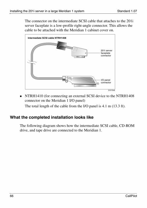
The connector on the intermediate SCSI cable that attaches to the 201i server faceplate is a low-profile right-angle connector. This allows the cable to be attached with the Meridian 1 cabinet cover on.
NTRH1410 (for connecting an external SCSI device to the NTRH1408 connector on the Meridian 1 I/O panel)
The total length of the cable from the I/O panel is 4.1 m (13.3 ft).
What the completed installation looks like
The following diagram shows how the intermediate SCSI cable, CD-ROM drive, and tape drive are connected to the Meridian 1.
G101548
Intermediate SCSI cable NTRH1408
201i serverfaceplate connector
I/O panelconnector

November 2006 Installing the 201i server in a large Meridian 1 system
201i Server Hardware Installation 67
In this diagram, the CD-ROM drive is the first device. The tape drive is the last device.
Note: Alternate SCSI device connection scenarios are supported, but are not depicted in this guide. If you want to use a connection scenario that is not described in this guide, ensure that you use appropriate cabling for each device.
Before you begin
Before you install the SCSI devices in a daisy chain, you must configure the SCSI device IDs and DIP switches. For instructions, refer to Chapter 7, “Preparing peripheral devices.”
Meridian 1
201i cabling Peripheral cabling
201iNTRH30AA
Optional
NTRH9038Tape drive
NTRH9105CD-ROMdrive
G101430
SCSI device cableNTRH3502
RearI/O panel
NTRH1408
NTRH1410

Installing the 201i server in a large Meridian 1 system Standard 1.07
68 CallPilot
To install the SCSI cables for Meridian 1
1 Thread the SCSI connector end of the NTRH1408 cable from the front of the Meridian 1 along the bottom of the shelf to either the left or the right access channel.
2 Leave the low-profile right-angle SCSI connector hanging for now. You will connect it later to the 201i server faceplate.
Note: The following diagram shows what the connection looks like after the cable is connected:
3 Thread the cable through the access channel to the back of the Meridian 1.
4 Attach the NTRH1408 cable to the inside of the I/O panel slot associated with the 201i server right slot.
5 Connect the NTRH1410 cable to the NTRH1408 cable connector on the I/O panel.
G101556
Access channels to rear of cabinet
201i server
IntermediateSCSI cableNTRH1408

November 2006 Installing the 201i server in a large Meridian 1 system
201i Server Hardware Installation 69
See the following diagram:
Note: The backplane connectors for the right slot are not required and, therefore, are left vacant.
6 Thread the NTRH1410 cable through the shelves below and out through the bottom of the Meridian 1 tower.
G101551
SCSI cableNTRH1410
Remove this cover
Cable routed from front
IntermediateSCSI cableNTRH1408

Installing the 201i server in a large Meridian 1 system Standard 1.07
70 CallPilot
7 Replace the protective plate.
8 Replace the I/O panel cover.
9 Power up the shelf.
What’s next?
Prepare the modem, CD-ROM drive, and tape drive for connection to the 201i server. For instructions, see Chapter 7, “Preparing peripheral devices.”

201i Server Hardware Installation 71
C h a p t e r 5
Installing the 201i server in an Option 11C or Option 11C Mini
In this chapterInstalling the 201i server in the Option 11C or Option 11C Mini switch 72
Section A: Installing Option 11C cables 77
Installing the intermediate SCSI cable for Option 11C 78
Section B: Installing Option 11C Mini cables 85
Installing the NTRH3502 SCSI cable for Option 11C Mini 86
Installing cables on the back of the Option 11C Mini cabinet 92

Installing the 201i server in an Option 11C or Option 11C Mini Standard 1.07
72 CallPilot
Installing the 201i server in the Option 11C or Option 11C Mini switch
Introduction
The 201i server occupies physical and electrical slots. The 201i server must be installed in two peripheral equipment slots as follows:
To position the 201i server on the switch shelf
1 Remove the front panel of the switch.
Note: On the Option 11C Mini, do the following:
a. Loosen the spring-loaded clips.
b. Slide the cover to the left.
c. Pull the cover up to remove it from the cabinet.
Switch Eligible slots
Option 11C Slots 1 through 9
Note: Both of the server backplane connectors must be installed in slots 1 through 9 to receive proper power. Neither connector can reside in slot 10.
Option 11C Mini A pair of consecutive slots in any cabinet
Note: You cannot install the 201i server in slots 0 or 4, because these slots are dedicated to other cards. For more information about cards and slots, refer to the Option 11C Mini documentation.

November 2006 Installing the 201i server in an Option 11C or Option 11C Mini
201i Server Hardware Installation 73
See the following diagram:
2 Ensure that no cables are connected to the slots in which you are installing the 201i server.
3 Open the lock latches at the top and bottom of the 201i server faceplate.
Note: When you open the top lock latch, it breaks the yellow backplane warning label, if the label has not been removed. The label is not relevant for Option 11C or Option 11C Mini. Remove the label and continue with this procedure.
G101559
A
C
B

Installing the 201i server in an Option 11C or Option 11C Mini Standard 1.07
74 CallPilot
4 Slide the 201i server into an unoccupied pair of slots.
Ensure that the 201i server is positioned correctly between the slots.
Note: When correctly inserted in the Option 11C Mini, the top of the 201i server is on the left. See the following diagram:
ATTENTION Do not push the 201i server into place against the backplane until you are ready to observe the startup cycle.
The 201i server receives power and starts as soon as the 201i server makes contact with the switch backplane.
G101588b

November 2006 Installing the 201i server in an Option 11C or Option 11C Mini
201i Server Hardware Installation 75
What’s next?
Continue with installing the cables. Refer to one of the following:
Section A: “Installing Option 11C cables,” on page 77
Section B: “Installing Option 11C Mini cables,” on page 85

Installing the 201i server in an Option 11C or Option 11C Mini Standard 1.07
76 CallPilot

November 2006 Installing the 201i server in an Option 11C or Option 11C Mini
201i Server Hardware Installation 77
Section A: Installing Option 11C cables
In this sectionInstalling the intermediate SCSI cable for Option 11C 78

Installing the 201i server in an Option 11C or Option 11C Mini Standard 1.07
78 CallPilot
Installing the intermediate SCSI cable for Option 11C
Introduction
Before you can connect an external CD-ROM or tape drive to the 201i server, Option 11C requires an intermediate SCSI cable (NTRH1407).
Note: If you are installing the 201i server in an Option 11C Mini, go to page 86.
Cable description
The connector on the NTRH1407 cable that attaches to the 201i server faceplate is a low-profile right-angle connector. This allows the SCSI device to be permanently connected to the 201i server with the Option 11C cabinet cover on.
The SCSI device connector end is equipped with a bracket assembly. This bracket assembly attaches to the Option 11C below the card cage. The CD-ROM or tape drive connects to this bracket assembly with the NTRH3502 cable that is provided with the device.

November 2006 Installing the 201i server in an Option 11C or Option 11C Mini
201i Server Hardware Installation 79
What the completed installation looks like
The following diagram shows how the intermediate SCSI cable, CD-ROM drive, and tape drive are connected to the Option 11C. The CD-ROM drive is the first device. The tape drive is the last device.
G101553
Option 11C SCSI cable NTRH1407
201i serverfaceplate connector
SCSIconnector
Drain wire
Bracketassembly

Installing the 201i server in an Option 11C or Option 11C Mini Standard 1.07
80 CallPilot
Note: Alternate SCSI device connection scenarios are supported, but are not depicted in this guide. If you want to use a connection scenario that is not described in this guide, ensure that you use appropriate cabling for each device.
Before you begin
Before you install the SCSI devices in a daisy chain, you must configure the SCSI device IDs and DIP switches. For instructions, see Chapter 7, “Preparing peripheral devices.”
Option 11C
201i cabling Peripheral cabling
201iNTRH30AA
Optional
NTRH9038Tape drive
NTRH9105CD-ROMdrive
CD-ROM drive SCSIcable NTRH3502
G101434
Tape drive SCSI cableNTRH3502
Bracketassembly
NTRH1407

November 2006 Installing the 201i server in an Option 11C or Option 11C Mini
201i Server Hardware Installation 81
To install the cable
1 Attach the bracket assembly and cable as follows:
a. Below the card cage, temporarily remove the hardware that secures cable connections to the Option 11C.
b. Temporarily remove any cabling that may interfere with the installation of the intermediate SCSI cable bracket assembly.
c. Remove the two screws on the right side of the Option 11C I/O panel.
d. Attach the intermediate SCSI cable bracket assembly, using the screws that were removed previously, so that the SCSI connector appears on the right side of the Option 11C cabinet.
.
CAUTION
Risk of equipment damageYou must power off the 201i server before connecting or disconnecting SCSI cables.
ATTENTION Before you disconnect the cabling, take the telephony equipment services associated with the cabling out of service.

Installing the 201i server in an Option 11C or Option 11C Mini Standard 1.07
82 CallPilot
See the following diagram:
2 Thread the cable up through the card cage.
Note: When routing the SCSI cable through the card cage, ensure the second cable ferrite is placed halfway through the opening.
3 Connect the grounding braid on the intermediate SCSI cable to the card cage, and tighten the screw.
G101554
A
D
C
B
Intermediate SCSI cable bracket assembly NTRH1407

November 2006 Installing the 201i server in an Option 11C or Option 11C Mini
201i Server Hardware Installation 83
4 Leave the low-profile right-angle SCSI connector loose for now. You will connect it later to the 201i server faceplate.
Note: The following diagram shows what the connection looks like after the cable is connected:
G101555
201i server
Position thesecond cableferrite so that it is halfway through opening.
IntermediateSCSI cableNTRH1407

Installing the 201i server in an Option 11C or Option 11C Mini Standard 1.07
84 CallPilot
5 Replace all cabling and hardware that you removed in step 1.
6 Restore any services that you took out of service in step 1.
What’s next?
Prepare the modem, CD-ROM drive, and tape drive for connection to the 201i server. For instructions, see Chapter 7, “Preparing peripheral devices.”

November 2006 Installing the 201i server in an Option 11C or Option 11C Mini
201i Server Hardware Installation 85
Section B: Installing Option 11C Mini cables
In this sectionInstalling the NTRH3502 SCSI cable for Option 11C Mini 86
Installing cables on the back of the Option 11C Mini cabinet 92

Installing the 201i server in an Option 11C or Option 11C Mini Standard 1.07
86 CallPilot
Installing the NTRH3502 SCSI cable for Option 11C Mini
Introduction
Before you can connect a CD-ROM or tape drive to the 201i server, you must install the NTRH3502 SCSI cable. The NTRH3502 SCSI cable routes the SCSI connection away from the 201i server faceplate so that an external SCSI device can remain permanently connected.
If the Option 11C Mini is equipped with a Fiber Routing Guide (consisting of a spool and mounting bracket), you must remove it before you can install the NTRH3502 SCSI cable, and then reinstall it when you are finished.
For detailed instructions on removing and installing the Fiber Routing Guide, refer to the Option 11C and Option 11C Mini Expansion Guide (NTP 553-3021-208).
What the completed installation looks like
The following diagram shows how the intermediate SCSI cable, CD-ROM drive, and tape drive are connected to the Option 11C Mini. In the diagram, the CD-ROM drive is the first device. The tape drive is the last device.

November 2006 Installing the 201i server in an Option 11C or Option 11C Mini
201i Server Hardware Installation 87
Note: Alternate SCSI device connection scenarios are supported, but are not depicted in this guide. If you want to use a connection scenario that is not described in this guide, ensure that you use appropriate cabling for each SCSI device.
Before you begin
1. Before you install the SCSI devices in a daisy chain, you must configure the SCSI device IDs and DIP switches.
For instructions, see Chapter 7, “Preparing peripheral devices.”
Option 11C Mini
201i cabling Peripheral cabling
201iNTRH30AA
Optional
NTRH9038Tape drive
NTRH9105CD-ROMdrive
CD-ROM drive SCSIcable NTRH3502
G101595
Tape drive SCSI cableNTRH3502
SCSI adapterA0769312
Installing the 201i server in an Option 11C or Option 11C Mini Standard 1.07
88 CallPilot
To install the NTRH3502 SCSI cable
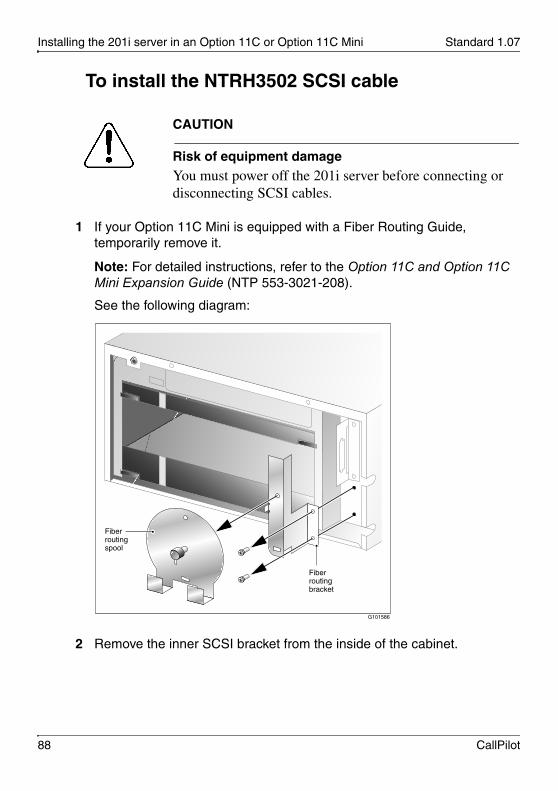
1 If your Option 11C Mini is equipped with a Fiber Routing Guide, temporarily remove it.
Note: For detailed instructions, refer to the Option 11C and Option 11C Mini Expansion Guide (NTP 553-3021-208).
See the following diagram:
2 Remove the inner SCSI bracket from the inside of the cabinet.
.
CAUTION
Risk of equipment damageYou must power off the 201i server before connecting or disconnecting SCSI cables.
G101586
Fiber routing spool
Fiber routing bracket

November 2006 Installing the 201i server in an Option 11C or Option 11C Mini
201i Server Hardware Installation 89
See the following diagram:
3 Refasten the inner SCSI bracket screws in their original locations inside the cabinet.
You will use the top screw later to fasten the NTRH3502 SCSI cable drain wire.
4 Connect the low-profile right-angle SCSI connector on the NTRH3502 cable to the SCSI connector on the 201i server faceplate.
5 Fasten the SCSI cable drain wire to the top screw that previously held the inner SCSI bracket in place.
G101587
Inner SCSIbracket
Note: After you remove the bracket, refasten the screws in their original locationsinside the cabinet.
Installing the 201i server in an Option 11C or Option 11C Mini Standard 1.07
90 CallPilot
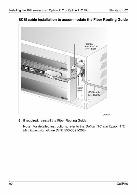
SCSI cable installation to accommodate the Fiber Routing Guide
6 If required, reinstall the Fiber Routing Guide.
Note: For detailed instructions, refer to the Option 11C and Option 11C Mini Expansion Guide (NTP 553-3021-208).
G101590
Drainwire
Ferrites from EMC kit NTRH3503
SCSI cable NTRH3502

November 2006 Installing the 201i server in an Option 11C or Option 11C Mini
201i Server Hardware Installation 91
See the following diagram:
7 Replace the cabinet cover.
What’s next?
Continue with “Installing cables on the back of the Option 11C Mini cabinet” on page 92.
G101591
Fiber routing spool
Fiber routing bracket
Note: Ensure the fiber routing spool and bracket are correctly aligned beforefastening them in place.

Installing the 201i server in an Option 11C or Option 11C Mini Standard 1.07
92 CallPilot
Installing cables on the back of the Option 11C Mini cabinet
Introduction
The following items connect to the back of the Option 11C Mini cabinet:
multi I/O cable (NTRH0912)
Option 11C Mini power cord with two ferrites
You must connect the multi I/O cable first before connecting the power cord, because the power cord routes over the multi I/O cable connection.
To connect the cables
1 On the rear of the Option 11C Mini cabinet, locate the connector associated with the first slot occupied by the 201i server.
2 Connect the NTRH0912 multi I/O cable as follows:
a. Loosen the connector’s Velcro fastening strap.
b. Connect the amphenol connector on the NTRH0912 multi I/O cable to the connector on the back of the Option 11C Mini cabinet.
c. Secure the connection by tightening the retaining screw and Velcro fastening strap of the connector.

November 2006 Installing the 201i server in an Option 11C or Option 11C Mini
201i Server Hardware Installation 93
The following diagram shows how to secure the multi I/O cable connection:
3 Attach the multi I/O cable drain wire to a screw on the cabinet.
See the diagram in step 4.
4 Connect the power cord to the Option 11C Mini cabinet.
G101592
A
B
C
Velcrofasteningstrap
Pull totighten thestrap

Installing the 201i server in an Option 11C or Option 11C Mini Standard 1.07
94 CallPilot
See the following diagram:
What’s next?
Prepare the modem, CD-ROM drive, and tape drive for connection to the 201i server. For instructions, see Chapter 7, “Preparing peripheral devices.”
G101593
Drain wire

201i Server Hardware Installation 95
C h a p t e r 6
Installing the 201i server in the Succession 1000 system
In this chapterSuccession 1000 description 96
Removing the Media Gateway or Media Gateway Expansion cover 104
Installing the 201i server 107
Installing the NTRH3502 SCSI cable for Succession 1000 110
Replacing the Media Gateway or Media Gateway Expansion cover 114
Connecting cables to the Succession 1000 system 117

Installing the 201i server in the Succession 1000 system Standard 1.07
96 CallPilot
Succession 1000 description
Introduction
The Succession 1000 system is an IP PBX that provides telephony and data capabilities over an IP network. The Succession 1000 system consists of the following major components:
Call Server
Media Gateway
Media Gateway Expansion
Call Server
The Call Server provides telephony services and call processing.
It supports up to four Media Gateways and four Media Gateway Expansions when the Small System Controller (SSC) card inside the unit is fully populated with two dual-port 100BaseT daughterboards.
The following connectors are located on the back of the Call Server:
four 100Base-T connectors for connecting Media Gateways using one of the following:
for connections over the LAN customer-supplied standard 100Base-T CAT5 Ethernet cables
for point-to-point connections (Nortel-supplied crossover Ethernet cables)
one 10Base-T Ethernet connector that
provides the ELAN interface to management software applications, such as Optivity Telephony Manager and CallPilot
accepts an industry-standard Medium Access Unit (MAU)
one SDI connector that interfaces with three TTY ports using a three-port SDI cable

November 2006 Installing the 201i server in the Succession 1000 system
201i Server Hardware Installation 97
one AC power cord connector and On/Off switch
The following diagram shows the Call Server:
Media Gateway and Media Gateway Expansion
The Media Gateway and Media Gateway Expansion provide the interface for analog or digital trunks, i2004 Internet phonesets, analog phonesets, and applications such as CallPilot.
A Media Gateway Expansion can be connected to the Media Gateway to increase system capacity.
Card slotsThe 201i server occupies physical and electrical slots. You must install the 201i server in a pair of consecutive slots in the Media Gateway or Media Gateway Expansion.
G101623

Installing the 201i server in the Succession 1000 system Standard 1.07
98 CallPilot
The following table identifies the Media Gateway and Media Gateway Expansion slots into which you can install the CallPilot 201i server:
For more information about cards and slots, refer to the Succession 1000 Planning and Installation Guide (NTP 553-3023-210).
Note: When you configure the Succession 1000 system, use the logical slot numbers shown in the following tables:
UnitThe 201i server can be installed in Ineligible slots
Media Gateway Slots 1 and 2
Slots 2 and 3
Slot 0 is dedicated to the SSC card.
Slot 4 (includes slots 5 and 6) is not used.
Media Gateway Expansion
Slots 7 and 8
Slots 8 and 9
Slots 9 and 10
Slot 10 is a double-wide slot. The second half of this slot does not have a backplane connector.
Media Gateway and Media Gateway Expansion 1
Media Gateway and Media Gateway Expansion 2
Physical slot Logical slot Physical slot Logical slot
Media Gateway Media Gateway
1 11 1 21
2 12 2 22
3 13 3 23
4 Not supported 4 Not supported
5 Not supported 5 Not supported

November 2006 Installing the 201i server in the Succession 1000 system
201i Server Hardware Installation 99
6 Not supported 6 Not supported
Media Gateway Expansion Media Gateway Expansion
7 17 7 27
8 18 8 28
9 19 9 29
10 20 10 30
Media Gateway and Media Gateway Expansion 3
Media Gateway and Media Gateway Expansion 4
Physical slot Logical slot Physical slot Logical slot
Media Gateway Media Gateway
1 31 1 41
2 32 2 42
3 33 3 43
4 Not supported 4 Not supported
5 Not supported 5 Not supported
6 Not supported 6 Not supported
Media Gateway and Media Gateway Expansion 1
Media Gateway and Media Gateway Expansion 2
Physical slot Logical slot Physical slot Logical slot

Installing the 201i server in the Succession 1000 system Standard 1.07
100 CallPilot
Back panel connectorsThe following table describes the connectors that are located on the back of each Media Gateway and Media Gateway Expansion, and how they relate to CallPilot:
Media Gateway Expansion Media Gateway Expansion
7 37 7 47
8 38 8 48
9 39 9 49
10 40 10 50
ConnectorMedia Gateway
Media Gateway Expansion
Four 50-pin amphenol connectors that interface with the cross-connect terminal
The CallPilot 201i server multi I/O cable must be connected to the connector that is associated with the first slot that the 201i server occupies. This is described in “Connecting cables to the Succession 1000 system” on page 117.
yes yes
One auxiliary (AUX) connector yes no
One SDI connector yes no
Media Gateway and Media Gateway Expansion 3
Media Gateway and Media Gateway Expansion 4
Physical slot Logical slot Physical slot Logical slot

November 2006 Installing the 201i server in the Succession 1000 system
201i Server Hardware Installation 101
The following diagram shows the Media Gateway:
One 10Base-T Ethernet connector that
provides the ELAN interface to management software applications such as Optivity Telephony Manager and CallPilot
accepts an industry-standard Medium Access Unit (MAU)
yes no
DS30X and CE-MUX connectors for connecting the Media Gateway and Media Gateway Expansions together
yes yes
Power connector yes yes
ConnectorMedia Gateway
Media Gateway Expansion
G101624

Installing the 201i server in the Succession 1000 system Standard 1.07
102 CallPilot
Note: Except for the back panel connectors, the Media Gateway Expansion is similar in external appearance to the Media Gateway.
Succession 1000 software
For the 201i server, the Succession 1000 system must be running Succession Release 3.00 (or later) software.
The Media Gateways and Media Gateway Expansions are centrally configured from the Call Server. This allows for a single point of management. Configuration required for correct CallPilot operation is, therefore, performed on the Call Server.
Administration softwareThe Succession 1000 system interfaces with Optivity Telephony Manager Release 1.1 (or later). Optivity Telephony Manager is an integrated suite of system management tools. You can use Optivity Telephony Manager to configure, control, and manage your Succession 1000 system. Optivity Telephony Manager operates on a platform that is compatible with a standard Windows PC.
Refer to the Optivity Telephony Manager documentation for information about the Optivity Telephony Manager application, its requirements, and how to install it.

November 2006 Installing the 201i server in the Succession 1000 system
201i Server Hardware Installation 103
Succession 1000 documentation
If you need to refer to the following Succession 1000 technical documents, they are stored on the Customer Documentation Library CD-ROM (NTLH80BA), provided with your Succession 1000 system:
Succession 1000 Planning and Installation Guide (NTP 553-3023-210)
Note: This guide is also provided in printed format with your Succession 1000 system.
Succession 1000 Input/Output X21 Administration (NTP 553-3023-311)
Succession 1000 Input/Output X21 Maintenance (NTP 553-3023-511)
You can search the entire suite of documentation online, or you can print part or all of a guide.

Installing the 201i server in the Succession 1000 system Standard 1.07
104 CallPilot
Removing the Media Gateway or Media Gateway Expansion cover
Introduction
To access the interior of the Media Gateway or Media Gateway Expansion, you must remove the front bezel and inside front cover plate.
To remove the front bezel and inside front cover plate
1 Remove the front bezel from the Media Gateway or Media Gateway Expansion as shown in the diagram on the next page.
.
WARNING
Risk of eye injuryNortel recommends that you operate the Media Gateway and Media Gateway Expansion with their front bezels installed. When the blue LEDs inside these units are lit, they are very bright.

November 2006 Installing the 201i server in the Succession 1000 system
201i Server Hardware Installation 105
a. Use a slot screwdriver to gently pry off the SUCCESSION label.
b. Insert the screwdriver approximately 2 cm (0.75 in.) into the open slot, and then gently lift the screwdriver handle, thus applying downward pressure on the tab inside the bezel.
At the same time, gently pull the bezel away from the chassis (approximately 2 cm [0.75 in.]) until the inside tab has cleared the catch.
c. Grasp the bezel by both sides and carefully pull it straight away from the Media Gateway or Media Gateway Expansion.
G101620
BC
A

Installing the 201i server in the Succession 1000 system Standard 1.07
106 CallPilot
2 Remove the inside front cover plate as follows:
a. Use a screwdriver to loosen each screw on the top of the inside front cover plate by three turns.
b. Apply pressure and slide the inside front cover plate upward to the left until the screw holes are aligned with the screw heads.
c. Pull the inside front cover plate away from the Media Gateway or Media Gateway Expansion.
What’s next?
Continue with “Installing the 201i server” on page 107.
ATTENTION Do not remove the screws.
G101621
A
C B

November 2006 Installing the 201i server in the Succession 1000 system
201i Server Hardware Installation 107
Installing the 201i server
Introduction
This section describes how to install the 201i server inside the Media Gateway or Media Gateway Expansion.
Before you beginDetermine which pair of consecutive slots are to contain the 201i server. The following table identifies the Media Gateway and Media Gateway Expansion slots into which the CallPilot 201i server can be installed:
Note: The 201i server will not function properly when installed in slots 3 and 4.
For more information about card slots, refer to the Succession 1000 Planning and Installation Guide (NTP 553-3023-210).
For the logical slot numbers that you must use when you configure the Succession 1000 system, see “Card slots” on page 97.
UnitThe 201i server can be installed in Ineligible slots
Media Gateway Slots 1 and 2
Slots 2 and 3
Slot 0 is dedicated to the SSC card.
Slot 4 (includes slots 5 and 6) is not used.
Media Gateway Expansion
Slots 7 and 8
Slots 8 and 9
Slots 9 and 10
Slot 10 is a double-wide slot. The second half of this slot does not have a backplane connector.

Installing the 201i server in the Succession 1000 system Standard 1.07
108 CallPilot
To install the 201i server inside the Media Gateway or Media Gateway Expansion
1 Ensure that no cables are connected to the slots in which you are installing the 201i server.
2 Open the lock latches at the top and bottom of the 201i server faceplate.
Note: When you open the top lock latch, it breaks the yellow backplane warning label if it has not been removed. The label is not relevant for Succession 1000. Remove the label and continue with this procedure.
3 Slide the 201i server into an unoccupied pair of slots.
Ensure that the 201i server is positioned correctly between the slots.
When correctly inserted, the top of the 201i server is on the left. See the following diagram:
G101588b

November 2006 Installing the 201i server in the Succession 1000 system
201i Server Hardware Installation 109
What’s next?
Continue with “Installing the NTRH3502 SCSI cable for Succession 1000” on page 110.
ATTENTION Do not push the 201i server into place against the backplane until you are ready to observe the startup cycle.
If the Media Gateway or Media Gateway Expansion is connected to a power source, the 201i server receives power as soon as it makes contact with the backplane.

Installing the 201i server in the Succession 1000 system Standard 1.07
110 CallPilot
Installing the NTRH3502 SCSI cable for Succession 1000
Introduction
Before you can connect a CD-ROM or tape drive to the 201i server, you must install the NTRH3502 SCSI cable. The NTRH3502 SCSI cable has a low profile right-angle connector that allows the cable to be connected to the 201i server faceplate when the Media Gateway or Media Gateway Expansion cover is installed. This allows the external SCSI device to remain permanently connected to the 201i server.
CD-ROM and tape drive cabling diagram
The following diagram shows how the intermediate SCSI cable, CD-ROM drive, and tape drive are connected to the 201i server. The CD-ROM drive is the first device. The tape drive is the last device:
Succession 1000Media Gateway orMedia GatewayExpansion
201i cabling Peripheral cabling
201iNTRH30AA
Optional
NTRH9038Tape drive
NTRH9105CD-ROMdrive
CD-ROM drive SCSIcable NTRH3502
G101615
Tape drive SCSI cableNTRH3502
SCSI adapterA0769312

November 2006 Installing the 201i server in the Succession 1000 system
201i Server Hardware Installation 111
Note: Alternate connection scenarios are supported, but are not depicted in this guide. If you want to use a connection scenario that is not described in this guide, ensure that you use appropriate cabling for each device.
Before you begin
1. Before you install the SCSI devices in a daisy chain, you must configure the SCSI device IDs and DIP switches. For instructions, see “Preparing peripheral devices,” on page 121.
To install the NTRH3502 cable
1 Remove the inner SCSI bracket from the inside of the Media Gateway or Media Gateway Expansion.
See the diagram on page 112.
.
CAUTION
Risk of equipment damageYou must power off the 201i server before connecting or disconnecting SCSI cables.

Installing the 201i server in the Succession 1000 system Standard 1.07
112 CallPilot
2 Refasten the inner SCSI bracket screws in their original locations inside the Media Gateway or Media Gateway Expansion.
You will use one of the screws later to fasten the NTRH3502 SCSI cable drain wire.
3 Connect the low profile right-angle SCSI connector on the NTRH3502 cable to the SCSI connector on the 201i server faceplate.
4 Fasten the SCSI cable drain wire to one of the screws that previously held the inner SCSI bracket in place.
Notes:
Use the screw that is the most convenient.
Press firmly on the drain wire Y-connector until it snaps into place around the screw post.
G101587
Inner SCSIbracket
Note: After you remove the bracket, refasten the screws in their original locationsinside the cabinet.
November 2006 Installing the 201i server in the Succession 1000 system
201i Server Hardware Installation 113
5 Replace the inside front cover plate.
For instructions, see “To replace the inside front cover plate” on page 114.
6 Replace the front bezel.
For instructions, see “To replace the front bezel” on page 116.
What’s next?
Continue with “Connecting cables to the Succession 1000 system” on page 117.
ATTENTION Ensure that the tabs on the bottom and right side of the inside front cover plate are positioned inside the Media Gateway or Media Gateway Expansion.

Installing the 201i server in the Succession 1000 system Standard 1.07
114 CallPilot
Replacing the Media Gateway or Media Gateway Expansion cover
Introduction
This section describes how to replace the front bezel and inside front cover plate on the Media Gateway or Media Gateway Expansion.
To replace the inside front cover plate
The following diagram provides an overview of how to install the inside front cover plate:
G101625
2
1
4
3

November 2006 Installing the 201i server in the Succession 1000 system
201i Server Hardware Installation 115
1 Insert the bottom tabs of the front cover plate inside the bottom rail.
2 Align the screw holes on the front cover plate over the screw heads on the Media Gateway or Media Gateway Expansion.
3 Slide the front cover plate downward to the right, ensuring that the side tabs slide behind the side rail.
4 Tighten the screws to secure the front cover plate.
5 Continue with “To replace the front bezel,” below.

Installing the 201i server in the Succession 1000 system Standard 1.07
116 CallPilot
To replace the front bezel
1 Align the two posts and the locking tab on the rear of the front bezel with the slots on the inside front cover plate.
2 Push the bezel toward the Media Gateway or Media Gateway Expansion until it snaps into place.
3 Replace the SUCCESSION label.
What’s next?
Continue with “Connecting cables to the Succession 1000 system” on page 117.
.
WARNING
Risk of eye injuryNortel recommends that you operate the Media Gateway and Media Gateway Expansion with their front bezels installed. When the blue LEDs inside these units are lit, they are very bright.
G101622

November 2006 Installing the 201i server in the Succession 1000 system
201i Server Hardware Installation 117
Connecting cables to the Succession 1000 system
Introduction
The following items are connected to the back of the Media Gateway or Media Gateway Expansion:
multi I/O cable (NTRH0912)
This cable establishes the connection to the modem, ELAN, and CLAN.
Media Gateway or Media Gateway Expansion power cord with two ferrites
You must connect the multi I/O cable first before connecting the power cord, because the power cord routes above the multi I/O cable connection.
To connect the cables
1 On the rear of the Media Gateway or Media Gateway Expansion, locate the connector associated with the first slot occupied by the 201i server.
2 Connect the NTRH0912 multi I/O cable as follows:
a. Loosen the connector’s Velcro fastening strap.
b. Connect the amphenol connector on the NTRH0912 multi I/O cable to the connector on the back of the Media Gateway or Media Gateway Expansion.

Installing the 201i server in the Succession 1000 system Standard 1.07
118 CallPilot
c. Secure the connection by tightening the retaining screw and Velcro fastening strap of the conductor.
The following diagram shows how to secure the multi I/O cable connection:
3 Attach the multi I/O cable drain wire to a screw on the Media Gateway or Media Gateway Expansion.
See the diagram in step 4.
G101592
A
B
C
Velcrofasteningstrap
Pull totighten thestrap

November 2006 Installing the 201i server in the Succession 1000 system
201i Server Hardware Installation 119
4 Connect the power cord to the Media Gateway or Media Gateway Expansion.
What’s next?
Prepare the modem, CD-ROM drive, and tape drive for connection to the 201i server. For instructions, see Chapter 7, “Preparing peripheral devices.”
G101616
Drain wire
Power cord
Note: Cabinet is not exactly as shown.

Installing the 201i server in the Succession 1000 system Standard 1.07
120 CallPilot

201i Server Hardware Installation 121
C h a p t e r 7
Preparing peripheral devices
In this chapterOverview 122
Setting the modem DIP switches 124
Setting the CD-ROM drive SCSI ID and DIP switches 126
Setting the tape drive SCSI ID 128
Setting SCSI device termination 130

Preparing peripheral devices Standard 1.07
122 CallPilot
Overview
Introduction
You can connect a modem and one or more SCSI devices to the 201i server.
The modem is connected to the 201i server by the multi I/O cable.
The SCSI devices are connected to the 201i server by the intermediate SCSI cable. If there is more than one SCSI device, the devices are daisy chained together. Each device on the SCSI bus must have a unique SCSI ID, and only the last device in the chain is terminated.
Supported SCSI devices
You need an external CD-ROM drive to upgrade, reinstall, and configure the 201i server. Since the CD-ROM drive is an external device, it requires its own AC power source.
You can use an external SCSI tape drive to back up and restore data. Since the tape drive is an external device, it also requires its own AC power source.
Note: You can optionally use the hard drive on an administration PC instead of a tape drive to perform and store backups.
This section discusses the following drives:
CD-ROM (NTRH9105): external SCSI CD-ROM drive
.
CAUTION
Risk of equipment damageThe CD-ROM and tape drives are not hot-pluggable. You must power off the 201i server before you connect or disconnect either drive.

November 2006 Preparing peripheral devices
201i Server Hardware Installation 123
tape drive (NTRH9038): Tandberg SLR5 tape drive
Note: This is currently the only supported tape drive.
DIP switches, SCSI ID, and SCSI device termination settings
For correct operation with the 201i server, you must set the following:
DIP switches on the modem and CD-ROM drive
SCSI ID and device termination on the CD-ROM and tape drives

Preparing peripheral devices Standard 1.07
124 CallPilot
Setting the modem DIP switches
Introduction
Set the modem DIP switches to their default settings. This section describes how to set the modem DIP switches if they have been changed from the default settings.
To set the modem DIP switches
Ensure that the DIP switches are set as described in the following table. Use a pair of tweezers or small screwdriver to set the DIP switches.
Note: The DIP switches are located on the back of the modem. ON is down. OFF is up.
DIPswitch
Default setting Function
1 OFF Data Terminal Ready (DTR) override
OFF: Normal DTR operations (The computer must provide a DTR signal for the modem to accept commands. When DTR is dropped, the call is terminated.)
ON: Modem ignores DTR (override)
2 OFF Verbal/numeric result codes
OFF: Displays verbal (word) results
ON: Displays numeric results
3 ON Result code display
OFF: Suppresses result codes
ON: Enables result codes

November 2006 Preparing peripheral devices
201i Server Hardware Installation 125
4 OFF Command mode local echo suppression
OFF: Displays keyboard commands
ON: Suppresses echo
5 ON Auto answer suppression
OFF: Modem answers on first ring, or higher if specified in NVRAM
ON: Disables auto answer
6 OFF Carrier Detect (CD) override
OFF: Modem sends CD signal when it connects with another modem; drops CD on disconnect
ON: CD is always ON (override)
7 OFF Power-on and ATZ reset software defaults
OFF: Loads Y or Y1 configuration from user-defined nonvolatile memory (NVRAM)
ON: Loads &F0-Generic template from read-only memory (ROM)
8 ON AT command set recognition
OFF: Disables command recognition (dumb mode)
ON: Enables recognition (smart mode)
DIPswitch
Default setting Function
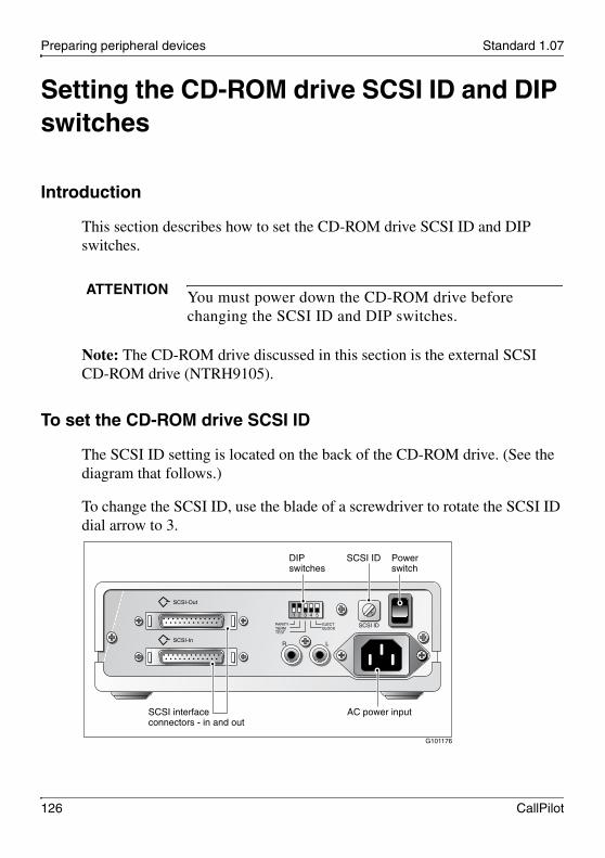
Preparing peripheral devices Standard 1.07
126 CallPilot
Setting the CD-ROM drive SCSI ID and DIP switches
Introduction
This section describes how to set the CD-ROM drive SCSI ID and DIP switches.
Note: The CD-ROM drive discussed in this section is the external SCSI CD-ROM drive (NTRH9105).
To set the CD-ROM drive SCSI ID
The SCSI ID setting is located on the back of the CD-ROM drive. (See the diagram that follows.)
To change the SCSI ID, use the blade of a screwdriver to rotate the SCSI ID dial arrow to 3.
ATTENTION You must power down the CD-ROM drive before changing the SCSI ID and DIP switches.
G101176
SCSI-Out
SCSI-In
SCSI ID
R L
1 2 3 4 5
SCSI interfaceconnectors - in and out
AC power input
Power switch
SCSI IDDIP switches
PARITYTERMTEST
EJECTBLOCK

November 2006 Preparing peripheral devices
201i Server Hardware Installation 127
To set the CD-ROM drive DIP switchesSet the CD-ROM drive DIP switches as described in the following table:
What’s next?
If you are also installing a tape drive, set the tape drive SCSI ID (see page 128); otherwise, set the CD-ROM drive device termination (see page 130).
DIP switch Description Setting
1 Parity ON
2 Termination Note: For more information about daisy chaining SCSI devices, see “Setting SCSI device termination” on page 130.
If the CD-ROM drive is the first and only device, set this switch to ON.
If the CD-ROM drive is the first device and daisy chained with the tape drive, set this switch to OFF.
3 Test OFF (for factory use only)
4 Block OFF
5 Eject OFF
Note: If this switch is set to ON, the eject button on the CD-ROM drive is disabled. To eject the CD-ROM from the drive, a software eject command must be sent over the SCSI bus.

Preparing peripheral devices Standard 1.07
128 CallPilot
Setting the tape drive SCSI ID
Introduction
This section describes how to set the tape drive SCSI ID.
Note: The tape drive discussed in this section is the Tandberg SLR5 tape drive (NTRH9038). This is currently the only supported tape drive.
To set the tape drive SCSI ID
The SCSI ID setting is located on the back of the tape drive. See the diagram on page 129.
Note: The appearance and size of the tape drive cabinet is subject to change. The diagram is an example of the key components.
ATTENTION You must power down the tape drive before changing the SCSI ID.

November 2006 Preparing peripheral devices
201i Server Hardware Installation 129
To change the SCSI ID, use the blade of a screwdriver to press either the plus (+) or minus (–) button on the SCSI ID switch. Set the SCSI ID to 5.
G101183
AC powerreceptacle
Note: The appearance and size of the tape drive is subject to change. This diagram is anexample of the key components on the tape drive's connection panel.
SCSI IDswitch
SCSIinterface connectors
Internallyterminated

Preparing peripheral devices Standard 1.07
130 CallPilot
Setting SCSI device termination
Introduction
If you want to connect SCSI devices in a daisy chain, the last device in the daisy chain must be terminated. This section describes how to terminate the SCSI devices.
Supported daisy chain connection scenarios
The first device in a SCSI device daisy chain can be either the tape drive or the CD-ROM drive. However, because the Tandberg SLR5 tape drive is already internally terminated at the factory, Nortel recommends that you connect the tape drive as the last device.
The following diagrams show the supported daisy chain and SCSI cable connections for your switch. The CD-ROM drive is the first device in the daisy chain. The tape drive is the last device.
ATTENTION Ensure that the CD-ROM and tape drives are powered down before changing the device termination.

November 2006 Preparing peripheral devices
201i Server Hardware Installation 131
Meridian 1For more information about the cabling requirements, see “Installing the SCSI cables for Meridian 1” on page 65.
SCSI device cabling for Meridian 1
Optional
NTRH9038Tape drive
NTRH9105CD-ROMdrive
NTRH1410
G101431
SCSI device cableNTRH3502
To Meridian 1

Preparing peripheral devices Standard 1.07
132 CallPilot
Option 11C, Option 11C MiniFor more information about the cabling requirements, see one of the following:
“Installing the intermediate SCSI cable for Option 11C” on page 78
“Installing the NTRH3502 SCSI cable for Option 11C Mini” on page 86
SCSI device cabling for Option 11C or Option 11C Mini
Optional
NTRH9038Tape drive
NTRH9105CD-ROMdrive
CD-ROM drive SCSIcable NTRH3502
G101436
Tape drive SCSI cableNTRH3502
To Option 11C orOption 11C Mini

November 2006 Preparing peripheral devices
201i Server Hardware Installation 133
Succession 1000For more information about the cabling requirements, see “Installing the NTRH3502 SCSI cable for Succession 1000” on page 110.
To set device termination
Terminate the SCSI devices as described in the following table:
IF you are connecting THEN
a CD-ROM drive only set DIP switch 2 on the back of the CD-ROM drive to ON. This terminates the drive.
SCSI device cabling for Succession 1000
Optional
NTRH9038Tape drive
NTRH9105CD-ROMdrive
CD-ROM drive SCSIcable NTRH3502
G101618
Tape drive SCSI cableNTRH3502
To Succession 1000Media Gateway orMedia GatewayExpansion

Preparing peripheral devices Standard 1.07
134 CallPilot
What’s next?
Complete the 201i server installation in the switch. See Chapter 8, “Connecting peripheral devices to the 201i server.”
a tape drive only do nothing.
External termination is not required because the drive is already internally terminated. This is indicated by a label on the back or front of the tape drive.
both a CD-ROM drive and a tape drive (the tape drive is the last device)
set DIP switch 2 on the back of the CD-ROM drive to OFF.
The tape drive is internally terminated. External termination is not required.
IF you are connecting THEN
201i Server Hardware Installation 135
C h a p t e r 8
Connecting peripheral devices to the 201i server
In this chapterOverview 136
Installing the MPCs 140
Installing the monitor, keyboard, and mouse 142
Connecting the CD-ROM and tape drives 144
Connecting the 201i server to the switch, ELAN, and CLAN 153
Connecting the modem 156
Completing the installation 159

Connecting peripheral devices to the 201i server Standard 1.07
136 CallPilot
Overview
Introduction
This section describes installing the 201i server in the switch, connecting peripheral devices, and starting the 201i server.
Connecting the 201i server to the network
The switch, ELAN, CLAN, and modem connections are established by using the 201i server multi I/O cable.
The switch connector is a 50-pin amphenol connector.
The RJ-45 CLAN and ELAN connectors support the following network protocols:
ELAN: 10Base-T Ethernet
CLAN: 10/100Base-T Ethernet
The modem connector is a 9-pin male RS-232 connector. To connect this cable to the modem, you also need a 25-pin male to 9-pin female shielded serial cable (A0601464, supplied with the modem).
Connecting peripheral devices
MPC cardsTwo MPC-8 cards are preinstalled at the factory. This section describes how to install additional cards, if required.
CD-ROM and tape drivesBefore you connect CD-ROM and tape drives, ensure that you have set the SCSI ID, termination, and DIP switches as described in Chapter 7, “Preparing peripheral devices.”

November 2006 Connecting peripheral devices to the 201i server
201i Server Hardware Installation 137
Monitor, keyboard, and mouseConnect the monitor, keyboard, and mouse to the 201i server faceplate so that you can:
observe the 201i server startup process.
run the Configuration Wizard.
perform initial administration after installation.
The 201i server is not intended to operate with permanent monitor, keyboard, and mouse connections. Once you have successfully started and configured the 201i server, remove the monitor, keyboard, and mouse. For day-to-day administration, use a web browser on a PC that is connected to the ELAN or CLAN.
ModemThe modem must be connected to the 201i server if:
you want to administer the 201i server from a remote location.
you need assistance from Nortel technical support.

Connecting peripheral devices to the 201i server Standard 1.07
138 CallPilot
201i server faceplate and peripheral device connectors
The following diagram identifies the peripheral device connectors and slots on the 201i server faceplate:
G101444
Keyboard connector
Mouse connector
Monitor connector
MPC slots 4 and 5
MPC slots 2 and 3
SCSI connector

November 2006 Connecting peripheral devices to the 201i server
201i Server Hardware Installation 139
Starting the 201i server
When you lock the 201i into position against the switch backplane, the server starts automatically. You can observe the startup process on both the monitor and the 201i server faceplate.
Before you begin
Before you connect the peripheral devices, ensure that you have completed the following tasks:
1. Set the DIP switches on the external fax modem. See page 124.
2. Prepare the SCSI CD-ROM and tape drives. See the following:
“Setting the CD-ROM drive SCSI ID and DIP switches” on page 126
“Setting the tape drive SCSI ID” on page 128
“Setting SCSI device termination” on page 130
ATTENTION Ensure that all peripheral devices are connected before you lock the 201i server in position against the backplane.
The 201i server receives power and starts when the connection with the backplane is established.

Connecting peripheral devices to the 201i server Standard 1.07
140 CallPilot
Installing the MPCs
Introduction
Two MPCs are preinstalled at the factory. This section describes how to install additional cards, if required.
Correct card insertion
The MPC-8 card is keyed so that it fits only one way into the slot on the 201i server faceplate. If the card is inserted incorrectly, the card does not go all the way into the slot.
To install the MPCs
1 Do one of the following:
2 Ensure that the MPC-8 card label is facing one of the following ways:
facing up if the 201i server is lying horizontally on a flat surface, with the top lock latch on the left
.
CAUTION
Risk of equipment damageIf you force the card into the slot incorrectly, you can damage the MPC-8 card and 201i server.
IF THEN
MPCs are already installed
ensure that they are firmly seated in their slots.
you want to install additional MPCs
continue with the rest of this procedure.

November 2006 Connecting peripheral devices to the 201i server
201i Server Hardware Installation 141
facing to the right if the 201i server is inserted into the 201i shelf (see the following diagram)
3 Insert the card into the slot, and gently push it until it is firmly in place and the ejector button pops back out.
Note: Populate MPC slots in numerical order as listed on the 201i server faceplate.
What’s next?
Continue with “Installing the monitor, keyboard, and mouse” on page 142.
G101541

Connecting peripheral devices to the 201i server Standard 1.07
142 CallPilot
Installing the monitor, keyboard, and mouse
Introduction
You must connect the monitor, keyboard, and mouse to the 201i server so that you can:
observe the 201i server startup process.
run the Configuration Wizard.
perform initial administration after installation.
Note: The 201i server is not intended to operate with permanent monitor, keyboard, and mouse connections. Once you have successfully started and configured the 201i server, remove the monitor, keyboard, and mouse. For day-to-day administration, use a web browser on a PC that is connected to the ELAN or CLAN.
Hardware requirement
.
CAUTION
Risk of equipment damageThe mouse connector on the 201i faceplate is a PS/2 connector. If you plan to use a USB mouse with USB-to-PS/2 converter, you must also use the Nortel-supplied 4-inch PS/2 extension cable (A0855616).
Without the extension cable, the USB-to-PS/2 mouse connector is partially blocked by the monitor connector.

November 2006 Connecting peripheral devices to the 201i server
201i Server Hardware Installation 143
PS/2 extension cableThe following diagram shows the PS/2 extension cable connected between the 201i server and the USB mouse with USB-to-PS/2 converter.
To connect the monitor, keyboard, and mouse
1 Connect the monitor to the 201i server faceplate using a DB-15 cable.
2 Connect the monitor power cord, and then power up the monitor.
3 Connect the keyboard and mouse to the 201i server faceplate using standard PS/2 connectors.
What’s next?
Continue with “Connecting the CD-ROM and tape drives” on page 144.
G101619
201i server faceplate
PS/2 extension cable(A0855616)
Monitor cable
USB-to-PS/2 converter

Connecting peripheral devices to the 201i server Standard 1.07
144 CallPilot
Connecting the CD-ROM and tape drives
Introduction
You can connect the CD-ROM, tape drive, or both to the intermediate SCSI cable that you installed earlier.
Before you begin
Before you can connect the CD-ROM or tape drive, ensure that you have completed the following tasks:
1. Install the intermediate SCSI cable.
2. Set the SCSI ID and device termination settings as described in
“Setting the CD-ROM drive SCSI ID and DIP switches” on page 126
“Setting SCSI device termination” on page 130
For See
Meridian 1 “Installing the SCSI cables for Meridian 1” on page 65.
Option 11C “Installing the intermediate SCSI cable for Option 11C” on page 78.
Option 11C Mini “Installing the NTRH3502 SCSI cable for Option 11C Mini” on page 86.
Succession 1000 “Installing the NTRH3502 SCSI cable for Succession 1000” on page 110.

November 2006 Connecting peripheral devices to the 201i server
201i Server Hardware Installation 145
Selecting the procedure for your switch
To connect the CD-ROM and tape drives to the 201i server (Meridian 1)
Note: If you are connecting the SCSI devices to the Option 11C, go to page 147. If you are connecting the SCSI devices to the Option 11C Mini, go to page 149.
1 Connect the first SCSI device.
2 Follow instructions below:
IF you are working with THEN see
a large Meridian 1 switch (such as Option 51)
“To connect the CD-ROM and tape drives to the 201i server (Meridian 1)” on page 145.
Option 11C “To connect the CD-ROM and tape drives to the 201i server (Option 11C)” on page 147.
Option 11C Mini “To connect the CD-ROM and tape drives to the 201i server (Option 11C Mini)” on page 149.
Succession 1000 “To connect the CD-ROM and tape drives to the 201i server (Succession 1000)” on page 151.
IF the first device is the THEN
CD-ROM drive connect the CD-ROM drive to the NTRH1410 cable that you connected earlier to the Meridian 1 I/O panel.
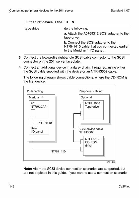
Connecting peripheral devices to the 201i server Standard 1.07
146 CallPilot
3 Connect the low-profile right-angle SCSI cable connector to the SCSI connector on the 201i server faceplate.
4 Connect an additional device in a daisy chain, if required, using either the SCSI cable supplied with the device or an NTRH3502 cable.
The following diagram shows cable connections, where the CD-ROM is the first device:
Note: Alternate SCSI device connection scenarios are supported, but are not depicted in this guide. If you want to use a connection scenario
tape drive do the following:
a. Attach the A0769312 SCSI adapter to the tape drive.
b. Connect the SCSI adapter to the NTRH1410 cable that you connected earlier to the Meridian 1 I/O panel.
IF the first device is the THEN
Meridian 1
201i cabling Peripheral cabling
201iNTRH30AA
Optional
NTRH9038Tape drive
NTRH9105CD-ROMdrive
G101430
SCSI device cableNTRH3502
RearI/O panel
NTRH1408
NTRH1410

November 2006 Connecting peripheral devices to the 201i server
201i Server Hardware Installation 147
that is not described in this guide, ensure that you use appropriate cabling for each SCSI device.
5 Connect the power cord for each device.
6 Power up the devices.
7 Continue with “What’s next?” on page 152.
To connect the CD-ROM and tape drives to the 201i server (Option 11C)
1 Connect the first SCSI device.
2 Follow instructions below:
3 Connect the low-profile right-angle SCSI cable connector to the SCSI connector on the 201i server faceplate.
4 Connect an additional device in a daisy chain, if required, using either the SCSI cable supplied with the device or an NTRH3502 cable.
IF the first device is the THEN
CD-ROM drive connect the NTRH3502 SCSI cable from the CD-ROM drive to the SCSI connector that is located on the intermediate SCSI cable bracket assembly (NTRH1407) on the Option 11C.
tape drive do the following:
a. Attach the A0769312 SCSI adapter to the tape drive.
b. Connect the NTRH3502 SCSI cable from the adapter to the SCSI connector that is located on the intermediate SCSI cable bracket assembly (NTRH1407) on the Option 11C.

Connecting peripheral devices to the 201i server Standard 1.07
148 CallPilot
The following diagram shows cable connections, where the CD-ROM drive is the first device:
Note: Alternate SCSI device connection scenarios are supported, but are not depicted in this guide. If you want to use a connection scenario that is not described in this guide, ensure that you use appropriate cabling for each SCSI device.
5 Connect the power cord for each device.
6 Power up the devices.
7 Continue with “What’s next?” on page 152.
Option 11C
201i cabling Peripheral cabling
201iNTRH30AA
Optional
NTRH9038Tape drive
NTRH9105CD-ROMdrive
CD-ROM drive SCSIcable NTRH3502
G101434
Tape drive SCSI cableNTRH3502
Bracketassembly
NTRH1407

November 2006 Connecting peripheral devices to the 201i server
201i Server Hardware Installation 149
To connect the CD-ROM and tape drives to the 201i server (Option 11C Mini)
1 Connect the first SCSI device.
2 Follow instructions below.
3 Connect the low-profile right-angle SCSI cable connector to the SCSI connector on the 201i server faceplate
4 Connect an additional device in a daisy chain, if required, using either the SCSI cable supplied with the device or an NTRH3502 cable.
The following diagram shows cable connections, where the CD-ROM drive is the first device:
IF the first device is the THEN
CD-ROM drive do the following:
a. Attach the A0769312 SCSI adapter to the CD-ROM drive.
b. Connect the NTRH3502 SCSI cable that you installed earlier on the Option 11C Mini to the SCSI adapter on the CD-ROM drive.
tape drive connect the NTRH3502 SCSI cable that you installed earlier on the Option 11C Mini to the tape drive.

Connecting peripheral devices to the 201i server Standard 1.07
150 CallPilot
Note: Alternate SCSI device connection scenarios are supported, but are not depicted in this guide. If you want to use a connection scenario that is not described in this guide, ensure that you use appropriate cabling for each SCSI device.
5 Connect the power cord for each device.
6 Power up the devices.
7 Continue with “What’s next?” on page 152.
Option 11C Mini
201i cabling Peripheral cabling
201iNTRH30AA
Optional
NTRH9038Tape drive
NTRH9105CD-ROMdrive
CD-ROM drive SCSIcable NTRH3502
G101595
Tape drive SCSI cableNTRH3502
SCSI adapterA0769312

November 2006 Connecting peripheral devices to the 201i server
201i Server Hardware Installation 151
To connect the CD-ROM and tape drives to the 201i server (Succession 1000)
1 Connect the first SCSI device.
2 Follow instructions below:
3 Connect an additional device in a daisy chain if required, using either the SCSI cable supplied with the device or an NTRH3502 cable.
IF the first device is the THEN
CD-ROM drive do the following:
a. Attach the A0769312 SCSI adapter to the CD-ROM drive.
b. Connect the NTRH3502 SCSI cable that you installed earlier on the Succession 1000 Media Gateway or Media Gateway Expansion to the SCSI adapter on the CD-ROM drive.
tape drive connect the NTRH3502 SCSI cable that you installed earlier on the Succession 1000 Media Gateway or Media Gateway Expansion to the tape drive.

Connecting peripheral devices to the 201i server Standard 1.07
152 CallPilot
The following diagram shows cable connections, where the CD-ROM drive is the first device:
Note: Alternate SCSI device connection scenarios are supported, but are not depicted in this guide. If you want to use a connection scenario that is not described in this guide, ensure that you use appropriate cabling for each SCSI device.
4 Connect the power cord for each device.
5 Power up the devices.
What’s next?
Continue with “Connecting the 201i server to the switch, ELAN, and CLAN” on page 153.
Succession 1000Media Gateway orMedia GatewayExpansion
201i cabling Peripheral cabling
201iNTRH30AA
Optional
NTRH9038Tape drive
NTRH9105CD-ROMdrive
CD-ROM drive SCSIcable NTRH3502
G101615
Tape drive SCSI cableNTRH3502
SCSI adapterA0769312

November 2006 Connecting peripheral devices to the 201i server
201i Server Hardware Installation 153
Connecting the 201i server to the switch, ELAN, and CLAN
Introduction
The CLAN and ELAN connections are established by using the 201i server multi I/O cable.
To establish the switch and network connections
1 Do one of the following:
ATTENTION For important considerations about using the Embedded LAN (ELAN) in your network, see “About the ELAN” in the CallPilot Installation and Configuration Task List.
IF you are installing the 201i server in a THEN
large Meridian 1 (for example, Option 51C)
ensure that the 50-pin amphenol connector on the multi I/O cable (NTRH0912) is connected to the newly installed backplane cable (NTRH3501) on the I/O panel at the rear of the switch.
Option 11C connect the 50-pin amphenol connector on the multi I/O cable (NTRH0912) to the high-density connector associated with the left slot occupied by the 201i server.

Connecting peripheral devices to the 201i server Standard 1.07
154 CallPilot
Note: Ensure that the cable is securely fastened.
2 If you have not already done so, connect the amphenol connector drain wire as follows:
Option 11C or Meridian 1 to the nearest backplane grounding bolt on the switch
The following diagram shows drain wire connection on the Option 11C.
Option 11C Mini or Succession 1000
ensure that the 50-pin amphenol connector on the multi I/O cable (NTRH0912) is connected to the high-density connector associated with the left slot occupied by the 201i server.
IF you are installing the 201i server in a THEN
G101552
Drain wire
Multi I/O cable NTRH0912

November 2006 Connecting peripheral devices to the 201i server
201i Server Hardware Installation 155
Option 11C Mini or Succession 1000 to a screw on the back of the cabinet
3 Connect the connector on the multi I/O cable that is labeled as ELAN to the switch network hub.
4 If CLAN is required, connect the connector on the multi I/O cable that is labeled as CLAN to the CLAN 10- or 100Base-T-compliant network hub.
What’s next?
Continue with “Connecting the modem” on page 156.
G101593
Drain wire

Connecting peripheral devices to the 201i server Standard 1.07
156 CallPilot
Connecting the modem
Introduction
You must connect the modem to the 201i server if:
you want to administer the 201i server from a remote location.
you need assistance from Nortel technical support.
Required equipment
To install the modem, you need the following items:
analog external modem that includes
RJ-11 analog phone cord
power adapter cord
56 kbps modem (NTRH9078)
25-pin male to 9-pin female shielded serial cable (A0601464)
two 0.25-inch nuts for installation between the following:
RS-232 connector thumbscrews on the multi I/O cable; maximum length 15 m (50 ft)
9-pin connector thumbscrews on the 25-pin male to 9-pin female shielded serial cable
analog line jack
To connect the modem
1 Ensure that the DIP switches are set as described in “Setting the modem DIP switches” on page 124.

November 2006 Connecting peripheral devices to the 201i server
201i Server Hardware Installation 157
2 Attach the serial cable as follows:
a. Connect the 25-pin male end of the serial cable to the modem.
b. Attach the 0.25-inch nuts to the thumbscrews on the 9-pin female connector on the serial cable.
c. Connect the 9-pin female connector to the RS-232 COM1 connector on the multi I/O cable and tighten the nuts.
3 Connect one end of the RJ-11 phone cord to the line jack on the modem and the other end to an analog jack.
4 Plug the power cord into an electrical outlet with an isolated ground.
5 Plug the other end of the power cord into the modem power connector.
Result: The back of the modem appears similar to the following:
.
CAUTION
Risk of equipment damage
Connect the modem to an analog line only. The use of a non-analog line (for example, digital or Multiline) can damage the modem.
G101445
RJ-11 connection
DIP switches
Switch positions:
Serial cable(RS-232)connection
Powerconnection
1 2 3 4 5 6 7 8
1 2 3 4 5 6 7 8
OFFON

Connecting peripheral devices to the 201i server Standard 1.07
158 CallPilot
6 Power on the modem.
Note: Ensure that the modem is receiving power by checking that at least one LED on its front panel is lit.
7 Place the modem in an area where it cannot be accidentally damaged or where people cannot trip over attached cords.
What’s next?
Continue with “Completing the installation” on page 159.

November 2006 Connecting peripheral devices to the 201i server
201i Server Hardware Installation 159
Completing the installation
Introduction
To complete the installation of the 201i server, lock the 201i into position. The server starts up automatically.
To complete the installation and start the 201i server
Note: Ensure that the switch in which the 201i is installed is powered on.
1 Ensure that all peripheral devices are powered up (including the 201i shelf).
2 Push the 201i server gently but firmly until it is flush with the backplane.
Result: The 201i server beeps for three seconds to indicate that power is being received.
3 Close the lock latches to secure the 201i server to the backplane.
4 Ensure that the power status LED is lit.
5 Watch the HEX display on the 201i server.
The HEX display shows T:01 through T:08, and then HOST. This takes about 13 seconds.
ATTENTION When connecting the optional CLAN, do not power up unless your antivirus programs and Nortel security updates are installed first.

Connecting peripheral devices to the 201i server Standard 1.07
160 CallPilot
Result: The operating system boot sequence begins, and communication with the switch occurs. The HEX display shows NT (for about 30 seconds), followed by OK.
Note: The system reboots more than once. The HEX display repeats with each reboot.
Note: Before OK appears, one of the following messages can appear, but not for more than one second: CDLN, C:01, or C:02. This is normal operation.
If OK does not appear, refer to the CallPilot server maintenance and diagnostics guide for your server for troubleshooting instructions.

November 2006 Connecting peripheral devices to the 201i server
201i Server Hardware Installation 161
6 Ensure that the operating system logon window appears on the monitor.
If the logon window does not appear, refer to the CallPilot <server model> Server Maintenance and Diagnostics guide for your server for troubleshooting instructions.
What’s next?
Proceed with the CallPilot <switch model> and CallPilot Server Configuration guide for your switch and server to connect and configure the server and switch.

Connecting peripheral devices to the 201i server Standard 1.07
162 CallPilot

201i Server Hardware Installation 163
A p p e n d i x A
RoHS part conversion table
In this appendixRoHS part conversion table 164

RoHS part conversion table Standard 1.07
164 CallPilot
RoHS part conversion table
This appendix provides a mapping of RoHS-compliant parts to the equivalent non-RoHS-compliant parts for the 201i server. Nortel is phasing in RoHS-compliant 201i servers in countries affected by the EUED (European Union Environmental Directives).
Use this table
during installation, to convert the non-RoHS part numbers used in this guide to their RoHS-compliant equivalentwhen ordering replacement parts for RoHS-compliant 201i servers

November 2006 RoHS part conversion table
201i Server Hardware Installation 165
Tabl
e 1:
RoH
S pa
rt c
onve
rsio
n ta
ble
Typ
e
Ro
HS
par
t d
escr
ipti
on
(The
non
-RoH
S p
art d
escr
iptio
n is
incl
uded
bel
ow in
par
enth
eses
if it
is
diff
eren
t fro
m th
e R
oHS
par
t des
crip
tion)
Ro
HS
PE
C
Co
de
No
n-R
oH
S
PE
C C
od
e
Pkg
201
i E5
Serv
er C
hass
is S
ub-A
ssem
bly
(Non
-RoH
S: C
allP
ilot
4.0
IP
E S
yste
m)
NT
UB
01C
AE
5N
TZ
E80
CA
Pkg
Cal
lPilo
t 4.
0 IP
E 2
01i M
igra
tion
Ser
ver
(Non
-RoH
S: C
allP
ilot
4.0
201
i Mig
rati
on S
erve
r)N
TZ
E84
AB
E5
NT
ZE
84A
B
Pkg
Cal
lPilo
t 4.
0 IP
E U
nifi
ed M
essa
ging
Sta
rter
Bun
dle
(EM
EA
Bun
dle)
NT
ZE
46B
AE
5N
TZ
E46
BA
Pkg
Cal
lPilo
t 4.
0 IP
E S
tand
-By
Syst
emN
TZ
E84
BA
E5
NT
ZE
84B
A
Pkg
Cal
lPilo
t 4.
0 IP
E 2
01i 2
4 M
PU
War
rant
y Sy
stem
NT
ZE
35O
BE
5N
TZ
E35
OB
Pkg
Cal
lPilo
t E
LA
N I
PE
Sys
- 1
6 M
PU
Exp
ansi
on K
it (
MP
Us
25 t
o 40
)N
TU
B91
AA
E5
NT
UB
91A
A
Pkg
IPE
H/W
Kit
for:
11C
Min
i, 10
00M
Cha
ssis
, Med
ia G
atew
ay 1
000B
, and
C
S 10
00S
NT
UB
93A
AE
5N
TU
B93
AA
Pkg
IPE
H/W
Kit
for:
Opt
ion
11C
, 100
0M C
abin
et, a
nd C
S 10
00E
NT
UB
93B
AE
5N
TU
B93
BA
Pkg
IPE
H/W
Kit
for:
Opt
ion
51C
– 8
1C, 1
000M
SG
, 100
0M H
G, a
nd 1
000
MG
NT
UB
93C
AE
5N
TU
B93
CA
Pkg
201i
Sup
port
Mod
em(N
on-R
oHS:
Cal
lPil
ot R
emot
e A
cces
s (R
AS)
Mod
em K
it)
NT
RH
9248
E6
NT
UB
16A
B
Pkg
Cal
lPilo
t E
xter
nal S
CSI
Tap
e D
rive
Kit
NT
UB
53B
AE
5N
TU
B53
AB

RoHS part conversion table Standard 1.07
166 CallPilot
Tabl
e 1:
RoH
S pa
rt c
onve
rsio
n ta
ble
(con
t’d)
Typ
e
Ro
HS
par
t d
escr
ipti
on
(The
non
-RoH
S p
art d
escr
iptio
n is
incl
uded
bel
ow in
par
enth
eses
if it
is
diff
eren
t fro
m th
e R
oHS
par
t des
crip
tion)
Ro
HS
PE
C
Co
de
No
n-R
oH
S
PE
C C
od
e
Pkg
Cal
lPilo
t E
xter
nal C
D-R
OM
Dri
ve K
itN
TU
B59
AC
E5
NT
UB
59A
C
FRU
MP
C-8
NT
RH
01A
AE
5N
TR
H01
AA
FRU
H/W
Por
tabl
e Ta
pe D
rive
Ass
embl
yN
TR
H92
36E
6N
TR
H90
38
FRU
H/W
Ass
y P
orta
ble
CD
RO
M D
rive
NT
RH
9105
E5
NT
RH
9105
FRU
SCSI
Ada
pter
, 50p
Cen
tron
ics
to H
DN
TR
H92
51E
6A
0769
312
FRU
SCSI
-3 A
dapt
er, 6
8p H
D M
ale
to 5
0p C
entr
onic
s F
emal
eN
TR
H92
58E
6A
0677
506
FRU
Mul
ti I
/O w
/ Dua
l Eth
erne
tN
TR
H09
12E
6N
TR
H09
12
FRU
M1
Unf
ilter
ed R
/T C
able
N
TR
H35
01E
6N
TR
H35
01
FRU
Ext
erna
l SC
SI T
ape
Cab
leN
TR
H35
02E
6N
TR
H35
02
FRU
14ft
Shi
elde
d E
ther
net
Cab
leN
TR
H92
50E
6A
0769
310
FRU
SCSI
Gen
der
Cha
nger
for
11C
Min
i / C
S 10
00S
NT
RH
9257
E6
A08
8247
6
FRU
Cab
le A
ssem
bly
for
Opt
ion
11C
SC
SI C
abin
etN
TR
H14
07E
6N
TR
H14
07
FRU
Cal
lPilo
t F
acep
late
to
Bul
khea
d SC
SI C
able
NT
RH
1408
E6
NT
RH
1408

November 2006 RoHS part conversion table
201i Server Hardware Installation 167
Tabl
e 1:
RoH
S pa
rt c
onve
rsio
n ta
ble
(con
t’d)
Typ
e
Ro
HS
par
t d
escr
ipti
on
(The
non
-RoH
S p
art d
escr
iptio
n is
incl
uded
bel
ow in
par
enth
eses
if it
is
diff
eren
t fro
m th
e R
oHS
par
t des
crip
tion)
Ro
HS
PE
C
Co
de
No
n-R
oH
S
PE
C C
od
e
FRU
M1
Bul
khea
d SC
SI C
able
NT
RH
1410
E6
NT
RH
1410
FRU
Ext
erna
l SC
SI T
ape
Cab
leN
TR
H35
02E
6N
TR
H35
02
FRU
Com
bo K
ey/M
ouse
(Non
-RoH
S: H
W P
erip
101
Enh
ance
d K
/Boa
rd)
NT
RH
9234
E5
NT
RH
9013
FRU
Com
bo K
ey/M
ouse
(Non
-RoH
S: 3
But
ton
Mou
se)
NT
RH
9234
E5
NT
RH
9014
FRU
15 I
nch
LC
D M
onit
or(N
on-R
oHS:
15"
Fla
t-pa
nel L
CD
Dis
play
Mon
itor
)N
TR
H92
35E
6N
0038
380
FRU
Spar
e C
lean
ing
Car
trid
ge(N
on-R
oHS:
Cle
anin
g C
artr
idge
)N
TR
H92
37A
0677
506
FRU
Spar
e SL
R75
Med
ia(N
on-R
oHS:
Dat
a C
artr
idge
4.0
/8.0
Ass
ocia
ted
wit
h Ta
ndbe
rg)
NT
RH
9238
A07
8024
7
Ref
O
nly
Nor
tel S
tand
ard
Secu
rity
Dev
ice
(Non
-RoH
S: S
ecur
ity
Dev
ice
(Don
gle)
)
NT
DK
57A
CE
6N
TD
K57
AA

RoHS part conversion table Standard 1.07
168 CallPilot

201i Server Hardware Installation 169
Index
Numerics201i server
components, diagram 18damaged, what to do 42faceplate
connections 31description 20 diagram 19, 138
inspecting 42installation
checklist 37–40prerequisites 44
installinglarge Meridian 1 systems 56Option 11C 72Option 11C Mini 72Succession 1000 108
motherboard, description 18network setup
Meridian 1 24Succession 1000 26
peripheral device connectors, diagram 138primary components 16relative humidity 22reset button 22RoHS compliance 16starting 139, 159–161Succession 1000 card slots 97–98, 107temperatures 22unpacking 41
Aadministration software 102attention
CD-ROM drive and settings 126, 128, 130tape drive and settings 126, 128, 130telephony equipment and their services 81
Bbackplane cable (tip and ring) 49, 62
establishing connections 64removing from Meridian 1 61
backplane connector, secondarydescription 48, 51diagram 51installing for Meridian1 52–55reason for moving 50required tools 52
booting the server 139, 159–161
Ccable, backplane (tip and ring) 49, 62
establishing connections 64removing from Meridian 1 61
cable, multi I/Oconnections, establishing
modem 156network 153switch 153

Index Standard 1.07
170 CallPilot
connectorsCLAN 29ELAN 29RS-232 30switch 29
diagram 28installing
large Meridian 1 system 153Option 11C 153Option 11C Mini 92, 154Succession 1000 154
cable, SCSI 110Meridian 1 49, 65
connections, establishing 69installing 68
NTRH1407, diagram 79Option 11C 78
bracket assembly, installing 82connections, establishing 83installing 81
Option 11C Mini 86installing 88–91
Succession 1000, installing 111–113cabling, SCSI devices
Meridian 1 131Option 11C 132Option 11C Mini 132Succession 1000 133
card slotsMPC 21Succession 1000 97–98
configuring 98–100cards, MPC-8
inserting correctly 140installing 140–141
cautionsbackplane connector 49modem and telephone line 157MPC card 140
CD-ROM driveback panel, diagram 126
connectingMeridian 1 145Option 11C 147Option 11C Mini 149Succession 1000 151
description 32device termination, setting 133DIP switches, setting 127installation, attention 126, 128, 130SCSI ID, setting 126
checklist, installation 37–40CLAN
LED 22requirements 28, 45
COM1 connector, multi I/O cable 30connecting 201i server to
CD-ROM driveMeridian 1 145Option 11C 147Option 11C Mini 149Succession 1000 151
keyboard 143modem 156monitor 143mouse 143network 153–155switch 153–155tape drive
Meridian 1 145Option 11C 147Option 11C Mini 149Succession 1000 151
connection requirements, Meridian 1 45, 48connector, secondary backplane
description 48, 51diagram 51installing for Meridian 1 52–55reason for moving 50
connectors201i server faceplate 31CLAN, multi I/O cable 29COM1, multi I/O cable 30ELAN, multi I/O cable 29

November 2006 Index
201i Server Hardware Installation 171
keyboard 20, 31monitor 20, 31mouse 20, 31SCSI 32SCSI device 21switch, multi I/O cable 29
copyright 2cover, removing
small Meridian 1 systems 73Succession 1000 104–106
covers, replacing Succession 1000 114–116
Ddaisy chaining SCSI devices
Meridian 1 131Option 11C 132Option 11C Mini 132Succession 1000 133
damaged server, what to do 42device termination, setting
CD-ROM drive 133tape drive 134
devices, peripheralCD-ROM drive 32Ethernet hub 33keyboard 33modem 33monitor 33mouse 33tape drive 33
devices, SCSIcabling diagrams
large Meridian 1 systems 67, 146Option 11C 80, 148Option 11C Mini 87, 150Succession 1000 110, 152
supported 122diagrams
201i servercomponents 18faceplate 19, 138
backplane (tip and ring) cable 62connections, establishing 64removing from Meridian 1 61
cable installationNTRH1408 68NTRH1410 68NTRH3502
Option 11C Mini 90Succession 1000 113
CD-ROM drive back panel 126cover removal
small Meridian 1 systems 73Succession 1000 105, 106
cover replacement, Succession 1000 114, 116
drain wire, connectingOption 11C 154Option 11C Mini 155Succession 1000 155
modem connections 157mouse, connecting 143MPC-8 card, correct installation 141multi I/O cable 28NTRH3501 cable 62power cord installation
Succession 1000 119SCSI cable
large Meridian 1 systems 65, 69Option 11C 79, 82, 83Option 11C Mini 90Succession 1000 113
SCSI device cablinglarge Meridian 1 systems 67, 146Option 11C 80, 148Option 11C Mini 87, 150Succession 1000 110, 152
secondary backplane connector 51Succession 1000 system
Call Server 97Media Gateway 101Media Gateway Expansion 101
tape drive, back panel 129DIP switches, setting

Index Standard 1.07
172 CallPilot
CD-ROM drive 127modem 124
documentation, Succession 1000 103drain wire, connecting
Option 11C 154Option 11C Mini 155Succession 1000 155
Eejector buttons, MPCs 21ELAN
LED 22requirements 28, 45
environmental specificationshumidity 22temperatures 22
Ethernet hub 33
Ffaceplate, 201i server
connections 31description 20 diagram 19, 138peripheral device connectors 138
fax modemconnecting 156DIP switches, setting 124
Gground, single point 36
Hhard drive LED 22hexadecimal (HEX) display 21humidity, 201i server 22
IIDs, setting SCSI
CD-ROM drive 126tape drive 128
infrared port 20inspecting the 201i server 42installing
201i serverlarge Meridian 1 systems 56overview 37–40prerequisites 44small Meridian 1 systems 72Succession 1000 system 108unpacking 41
MPC cards 140–141NTRH3501 backplane (tip and ring)
cable 63SCSI cable
Meridian 1 68Option 11C 81Option 11C Mini 88–91Succession 1000 111–113
secondary backplane connector for Meridian 1 52–55
intermediate SCSI cablediagrams
Meridian 1 connections, establishing 69Option 11C
bracket assembly, installing 82connections, establishing 83
installingon Meridian 1 68Option 11C 81
Kkeyboard 31
connecting 143connector 20description 33

November 2006 Index
201i Server Hardware Installation 173
Llatches, lock 20LEDs
CLAN 22ELAN 22hard drive 22MPC status 20–21power status 20SCSI drive 22
lock latches 20
MMedia Gateway and Media Gateway
Expansion See Succession 1000Meridian 1
backplane (tip and ring) cableexisting cables, removing 59NTRH3501, installing 63
connection requirements 45I/O panel connections 48network setup 24SCSI cables, installing 68slot requirements 44
modem 33connecting 156connections diagram 157DIP switches, setting 124
monitor 31connecting 143connector 20description 33
motherboard, 201i serverdescription 18
mouse 31connecting 143connection requirements 142connector 20description 33
MPCcard slots 21ejector buttons 21
status LEDs 20–21MPC-8 card 32
caution 140inserting correctly 140
diagram 141installing 140–141
multi I/O cable 28connections
modem 156network 153–155switch 153–155
descriptionCLAN connector 29ELAN connector 29RS-232 connector 30switch connector 29
installinglarge Meridian 1 system 153Option 11C 153Option 11C Mini 92Succession 1000 117–118
Nnetwork
connections, establishing with multi I/O cable 153–155
protocols, supported 27requirements 28, 44
NTRH0912 cable 28connections, establishing
network 153–155switch 153–155
installing 92large Meridian 1 system 153Option 11C 153Succession 1000 117–118
NTRH1407 cable 78diagram 79installation diagram 82, 83installing 81
NTRH1408 cable 58diagram 65

Index Standard 1.07
174 CallPilot
installation diagram 68installing 68
NTRH1410 cable 66installation diagram 68installing 68
NTRH3501 cable 58diagram 62installing 63
NTRH3502 cable 86, 110installation diagrams
Option 11C Mini 90Succession 1000 113
installingOption 11C Mini 88–91Succession 1000 111–113
OOption 11C Mini
multi I/O cable, installing 92power cable
installing 93SCSI cable 86
Option 11C, installing intermediate SCSI cable 81
Ppart numbers
CD-ROM drive 32Ethernet hub 33keyboard 33modem 33monitor 33mouse 33RoHS mapped to non-RoHS 164tape drive 33
peripheral devicesCD-ROM drive 32Ethernet hub 33keyboard 33
modem 33monitor 33mouse 33tape drive 33
power status LED, description 20protocols, supported network 27
Rregulatory information 2relative humidity, 201i server 22removing the backplane (tip and ring)
cables 59reset button, description 22RoHS
compliance for the 201i server 16parts list 164
RS-232 connector, multi I/O cable 30
SSCSI cable 49, 110
Meridian 1 65connections, establishing 69installing 68
NTRH1407, diagram 79Option 11C 78
bracket assembly, installing 82connections, establishing 83installing 81
Option 11C Mini 86installing 88–91
Succession 1000 111–113SCSI connectors 21, 32SCSI devices
cabling diagramslarge Meridian 1 systems 67, 146Option 11C 80, 148Option 11C Mini 87, 150Succession 1000 110, 152

November 2006 Index
201i Server Hardware Installation 175
daisy chain scenariosMeridian 1 131Option 11C 132Option 11C Mini 132Succession 1000 133
installation, attention 126, 128, 130supported 122
SCSI drive LED 22SCSI IDs, setting
CD-ROM drive 126tape drive 128
secondary backplane connectordescription 48, 51diagram 51installing for Meridian 1 52–55reason for moving 50required tools 52
server, 201icomponents, diagram 18damaged, what to do 42faceplate 19, 138inspecting 42installation
checklist 37–40prerequisites 44
installinglarge Meridian 1 systems 56Option 11C 72Option 11C Mini 72Succession 1000 108
network setupMeridian 1 24Succession 1000 26
peripheral device connectors, diagram 138primary components 16starting 139, 159–161unpacking 41
settingCD-ROM drive DIP switches 127device termination
CD-ROM drive 133tape drive 134
modem DIP switches 124SCSI IDs
CD-ROM 126tape drive 128
single-point ground 36slot configuration, Succession 1000 98–100slot requirements 44
small Meridian 1 systems 72Succession 1000 97–98, 107
softwareadministration 102Succession 1000 requirements 102
Succession 1000card slots 107
configuring 98–100covers, replacing 114–116documentation 103multi I/O cable, installing 117–118network setup 26power cable
installing 119SCSI cable 110slot requirements 44system description 96
Call Server 96Media Gateway 97Media Gateway Expansion 97software requirements 102
switchconnection, establishing with multi I/O
cable 153–155connector, multi I/O cable 29requirements 44
switches, setting DIPCD-ROM drive 127modem 124
Ttape drive
back panel, diagram 129

Index Standard 1.07
176 CallPilot
connectingMeridian 1 145Option 11C 147Option 11C Mini 149Succession 1000 151
description 33device termination, setting 134installation, attention 126, 128, 130setting SCSI ID 128
temperatures, 201i server 22tip and ring cable 49, 62
establishing connections 64installing NTRH3501 63removing 59removing from Meridian 1 61
trademarks 2
Wwarning, working with the switch
backplane 58


201i Server Hardware Installation
CallPilotRelease 4.0
Document Number: 555-7101-220
Document Version: Standard 1.07
November 2006
All Rights Reserved.
To provide feedback or report a problem in this document, go to www.nortel.com/documentfeedback.
The information in this document is subject to change without notice. The statements, configurations, technical data, and recommendations in this document are believed to be accurate and reliable, but are presented without express or implied warranty. Users must take full responsibility for their applications of any products specified in this document. The information in this document is proprietary to Nortel Networks.
*Nortel Networks, the Nortel Networks logo, and the Globemark are trademarks of Nortel Networks.
*Microsoft, MS, MS-DOS, Windows, and Windows NT are registered trademarks of Microsoft Corporation.
All other trademarks and registered trademarks are the property of their respective owners.