Call for Proposals - ec.europa.eu Health Monitoring ... SAGE-02-032 Durability study of electrical...
59
Clean Sky Joint Undertaking Call: SP1-JTI-CS-2013-02 Q&A Release 3 - 3 October 2013; Page 1 of 59 European Commission Research Directorates Call for Proposals: CLEAN SKY RESEARCH and TECHNOLOGY DEVELOPMENT PROJECTS (CS-RTD Projects): Questions and Answers Last Release Issued on 3 October 2013 Call Identifier SP1-JTI-CS-2013-02 The applicants are also invited to consult on the Clean Sky web site the presentations related to the following Info day(s) about Call 15: Brussels on 16 July 2013 Notes: - the answers are organized by sequence of submittal and response by Topic managers. - The outcome of the webinar sessions held on 20 and 25 September are included in the document
Transcript of Call for Proposals - ec.europa.eu Health Monitoring ... SAGE-02-032 Durability study of electrical...

Clean Sky Joint Undertaking
Call: SP1-JTI-CS-2013-02 Q&A Release 3 - 3 October 2013; Page 1 of 59
European Commission Research Directorates
Call for Proposals:
CLEAN SKY RESEARCH and TECHNOLOGY DEVELOPMENT PROJECTS
(CS-RTD Projects):
Questions and Answers
Last Release
Issued on 3 October 2013
Call Identifier
SP1-JTI-CS-2013-02
The applicants are also invited to consult on the Clean Sky web site the presentations related to the following Info day(s) about Call 15:
Brussels on 16 July 2013
Notes: - the answers are organized by sequence of submittal and response by Topic
managers. - The outcome of the webinar sessions held on 20 and 25 September are included
in the document

Clean Sky Joint Undertaking
Call: SP1-JTI-CS-2013-02 Q&A Release 3 - 3 October 2013; Page 2 of 59
European Commission Research Directorates
Contents SGO-02-073 Numerical and experimental cross analysis methodology for mechanical impacts on a composite
structure................................................................................................................................................................... 8
SGO-02-079 Optical Fibre based self-monitoring Motor Drives .......................................................................... 11
ECO-01-073 End of life assessment of Demonstrator B2 - Low weight green metallic fuselage panels" including
physical dismantling and recycling ....................................................................................................................... 12
SAGE-02-034 Health Monitoring - Wireless Sensors .......................................................................................... 12
GRA-01-052 Development and validation of methodologies and software tools for the implementation of
accurate transfer of loads between numerical models ........................................................................................... 14
SGO-02-052 Electrical Starter / Generator disconnect system ............................................................................. 14
ECO-01-072 Manufacturing optimisation of a plenum with GFRP cyanate ester-based prepreg......................... 15
SGO-02-079 Optical Fibre based self-monitoring Motor Drives .......................................................................... 15
SAGE-02-032 Durability study of electrical insulating material in aircraft engine chemical environment .......... 16
SGO-02-079 Optical Fibre based self-monitoring Motor Drives .......................................................................... 16
SFWA-03-014 Vibration reduction systems in pylon area ................................................................................... 17
SGO-02-073 Numerical and experimental cross analysis methodology for mechanical impacts on a composite
structure................................................................................................................................................................. 17
SGO-03-025 Automatic flight plan management tool for integration in bench of avionics equipment validation 17
SAGE-02-034 Health Monitoring - Wireless Sensors .......................................................................................... 18
SAGE-02-034 Health Monitoring - Wireless Sensors .......................................................................................... 19
SAGE-02-034 Health Monitoring - Wireless Sensors .......................................................................................... 20
SGO-02-066 HVDC fuses design, development, validation and integration ........................................................ 21
SFWA-03-014 Vibration reduction systems in pylon area ................................................................................... 23
SGO-02-079 Optical Fibre based self-monitoring Motor Drives .......................................................................... 23
SGO-02-078 Ice Phobic Coating Associated to Low Power Electromechanical Deicers ..................................... 23
GRA-01-052 Development and validation of methodologies and software tools for the implementation of
accurate transfer of loads between numerical models ........................................................................................... 24
SGO-02-079 Optical Fibre based self-monitoring Motor Drives .......................................................................... 25
ECO-01-072 Manufacturing optimisation of a plenum with GFRP cyanate ester-based prepreg......................... 25
GRA-01-052 Development and validation of methodologies and software tools for the implementation of
accurate transfer of loads between numerical models ........................................................................................... 25
ECO-01-073 End of life assessment of Demonstrator B2 - Low weight green metallic fuselage panels" including
physical dismantling and recycling ....................................................................................................................... 26
SAGE-02-035 Non-rigid geometry variation simulation for fabricated aero engine structures ............................ 26
GRA-01-052 Development and validation of methodologies and software tools for the implementation of
accurate transfer of loads between numerical models ........................................................................................... 26
SGO-02-079 Optical Fibre based self-monitoring Motor Drives .......................................................................... 27
SAGE-01-002 Fracture mechanic investigation of a new high temperature Ni-based casting alloy..................... 27
GRA-01-054 Flexible sensor co-operation for structural health diagnosis/prognosis........................................... 28
GRA-01-055 Development of novel inspection approaches and automated systems for monitoring CFRP
damages on-line .................................................................................................................................................... 28
SGO-02-082 Lithium-ion energy storage module for Integrated 28Vdc Modular Power system......................... 31
SAGE-06-003 Development of materials, processes, and means to enable the application of piezoelectric
materials in aero engine controls. .......................................................................................................................... 31
GRA-01-054 Flexible sensor co-operation for structural health diagnosis/prognosis........................................... 32
GRA-01-055 Development of novel inspection approaches and automated systems for monitoring CFRP
damages on-line .................................................................................................................................................... 32
SGO-02-076 Study, sizing, development, prototyping of high power density, preferably self-air cooled e-motor
and corresponding inverter .................................................................................................................................... 33
GRA-01-054 Flexible sensor co-operation for structural health diagnosis/prognosis........................................... 34
GRA-01-055 Development of novel inspection approaches and automated systems for monitoring CFRP
damages on-line .................................................................................................................................................... 34
SAGE-02-032 Durability study of electrical insulating material in aircraft engine chemical environment .......... 35
GRA-02-025 Highly-accurate/reliable WT tests for Community Noise assessment of an Advanced Turboprop
Regional A/C integrating HLD innovative low-noise design ............................................................................... 35

Clean Sky Joint Undertaking
Call: SP1-JTI-CS-2013-02 Q&A Release 3 - 3 October 2013; Page 3 of 59
European Commission Research Directorates
GRA-05-008 Highly-accurate/reliable WT tests for Community Noise assessment of an Advanced Geared
Turbofan Regional A/C integrating HLD innovative low-noise design ................................................................ 35
GRA-01-052 Development and validation of methodologies and software tools for the implementation of
accurate transfer of loads between numerical models ........................................................................................... 36
SGO-03-026 Antenna system design and testing for an avionic weather polarimetric X-band radar ................... 36
SAGE-02-034 Health Monitoring - Wireless Sensors .......................................................................................... 36
SGO-02-074 Thermoelectric cooling solutions in harsh environment. Design and prototyping .......................... 37
SGO-02-080 ECS humidity optimisation ............................................................................................................. 37
SAGE-02-034 Health Monitoring - Wireless Sensors .......................................................................................... 38
GRA-01-055 Development of novel inspection approaches and automated systems for monitoring CFRP
damages on-line .................................................................................................................................................... 39
SGO-04-009 Airline trials of green flight management functions ........................................................................ 39
GRA-01-055 Development of novel inspection approaches and automated systems for monitoring CFRP
damages on-line .................................................................................................................................................... 40
SGO-02-082 Lithium-ion energy storage module for Integrated 28Vdc Modular Power system......................... 40
SGO-02-076 Study, sizing, development, prototyping of high power density, preferably self-air cooled e-motor
and corresponding inverter .................................................................................................................................... 41
SGO-03-025 Automatic flight plan management tool for integration in bench of avionics equipment validation 41
SGO-02-081 Implementation carbon fibers for rotor of high speed rotating electric machine ........................... 41
ECO-01-072 Manufacturing optimisation of a plenum with GFRP cyanate ester-based prepreg......................... 43
SAGE-02-034 Health Monitoring - Wireless Sensors .......................................................................................... 43
SGO-02-076 Study, sizing, development, prototyping of high power density, preferably self-air cooled e-motor
and corresponding inverter .................................................................................................................................... 43
ECO-01-072 Manufacturing optimisation of a plenum with GFRP cyanate ester-based prepreg......................... 43
SAGE-02-032 Durability study of electrical insulating material in aircraft engine chemical environment .......... 44
SAGE-02-034 Health Monitoring - Wireless Sensors .......................................................................................... 44
GRA-01-052 Development and validation of methodologies and software tools for the implementation of
accurate transfer of loads between numerical models ........................................................................................... 45
SGO-03-025 Automatic flight plan management tool for integration in bench for avionics equipment validation
.............................................................................................................................................................................. 45
ECO-01-075 Manufacturing and optimisation of a PEEK scroll by fusible core injection moulding .................. 46
GRA-01-052 Development and validation of methodologies and software tools for the implementation of
accurate transfer of loads between numerical models ........................................................................................... 46
GRA-01-053 Characterization of Structural Behaviour for High Frequency Phenomena .................................... 47
SAGE-01-002 Fracture mechanic investigation of a new high temperature Ni-based casting alloy..................... 48
SFWA-03-014 Vibration reduction systems in pylon area ................................................................................... 48
SGO-03-025 Automatic flight plan management tool for integration in bench for avionics equipment validation
.............................................................................................................................................................................. 49
ECO-01-072 Manufacturing optimisation of a plenum with GFRP cyanate ester-based prepreg......................... 49
SGO-03-025 Automatic flight plan management tool for integration in bench for avionics equipment validation
.............................................................................................................................................................................. 50
SAGE-02-034 Health Monitoring - Wireless Sensors .......................................................................................... 50
SGO-02-073 Numerical and experimental cross analysis methodology for mechanical impacts on a composite
structure................................................................................................................................................................. 51
SFWA-02-042 In-Service Monitoring of LE Contamination................................................................................ 52
SGO-02-073 Numerical and experimental cross analysis methodology for mechanical impacts on a composite
structure................................................................................................................................................................. 52
SAGE-06-007 Validated Design Methodology for Fuel Manifold Systems ......................................................... 52
GRA-01-055 Development of novel inspection approaches and automated systems for monitoring CFRP
damages on-line .................................................................................................................................................... 53
GRA-01-053 Characterization of Structural Behaviour for High Frequency Phenomena .................................... 53
SAGE-02-035 Non-rigid geometry variation simulation for fabricated aero engine structures ............................ 53
SAGE-02-032 Durability study of electrical insulating material in aircraft engine chemical environment .......... 54
SFWA-02-043 Advanced measurement for Low Speed High scale CROR Wind tunnel test .............................. 54
ECO-01-072 Manufacturing optimisation of a plenum with GFRP cyanate ester-based prepreg......................... 55

Clean Sky Joint Undertaking
Call: SP1-JTI-CS-2013-02 Q&A Release 3 - 3 October 2013; Page 4 of 59
European Commission Research Directorates
SGO-02-076 Study, sizing, development, prototyping of high power density, preferably self-air cooled e-motor
and corresponding inverter .................................................................................................................................... 55
ECO-01-074 Application of bio materials based on bamboo fibers to cabin interior composite sandwich panels 56
SAGE-02-037 Innovative instrumentation for rotating gauges ............................................................................. 56
SGO-02-079 Optical Fibre based self-monitoring Motor Drives .......................................................................... 56
GRA-01-054 Flexible sensor co-operation for structural health diagnosis/prognosis........................................... 58

Clean Sky Joint Undertaking
Call: SP1-JTI-CS-2013-02 Q&A Release 3 - 3 October 2013; Page 5 of 59
European Commission Research Directorates
via a special mailbox [email protected].
All questions regarding the topics published in this Call can be addressed to:
[email protected] Questions received up until 20 September 2013 will be analysed. A first version of the Q/A document is relased before end of July. Another version will be released by 13 September 2013. The final version of the Q/A document will be released by end September 2013. Questions having a general value, either on procedural aspects or specific technical clarifications concerning the call topics, when judged worth being disseminated, will be published in a specific section of the web site (www.cleansky.eu), together with the answers provided by the topic managers. All interested applicants are suggested to consult periodically. The above mentioned mailbox is the only permitted channel for asking questions concerning this call. All questions and answers having a general value, either on procedural aspects or on specific technical clarifications concerning the call topics, when judged worth being disseminated, are published in this document. As stated in the call fiche, all interested parties are recommended to consult periodically the Clean Sky web site for updates to this document and any corresponding updates to the call fiche.

Clean Sky Joint Undertaking
Call: SP1-JTI-CS-2013-02 Q&A Release 3 - 3 October 2013; Page 6 of 59
European Commission Research Directorates
# Question / answer
1
The call refers to a funding between 50 and 75%.
Could you clarify how a value not exactly 50 or 75 can be obtained?
The single entity applying is eligible for either 50% or 75% depending on the legal status (for example industry or SME); in case of a consortium, both funding criteria will apply and the resulting funding will be an average of the two percentages, weighted by the actual contributions of each partner.
Example: A topic worth 100 k€ is proposed by a consortium formed by an industrial partner, developing activities for 80 k€, and by an SME providing 20 k€ effort; the resulting funding will be 55 k€ (80 * 50% + 20 * 75%), i.e. 55%
2
When applying to one topic, must the applicant fulfil all the special skills, certifications and
equipment listed in section 2 of the topic description? If one applicant cannot fulfil all the requirements, can a consortium be built so that the consortium meets all the requirements?
Of course you can build a consortium if needed.
With respect to usual Collaborative Research Calls, Clean Sky does not require a consortium as a constraint; even a single entity can apply. Of course, a consortium is also accepted.
3
What is the meaning of the number of pages for the proposal document, quoted in section
Remarks in some topics?
In some cases the ITD Topic manager has also estimated the expected size of the proposal document.
This must be considered an indication only, with no value of selection criteria. The applicant must assure a thorough description of the capabilities and the way to fulfil the topic requirement, in the suitable number of pages as necessary.
4
Among the six evaluation criteria there is none which specifically mentions "value for
money" or "costs". Is this element considered in the evaluation and if so, how?
The Call Text quotes: As indicated in section 4.6 of the "Rules for Participation and Rules for Submission of Proposals and the related Evaluation, Selection and Award Procedures", each proposal will be evaluated on 6 criteria. The Rules for Participation quote: The proposal will be evaluated against six pre-determined evaluation criteria: - C1: Technical excellence, - C2: Innovative character, - C3: Compliance with the Call for Proposals specification and timetable (relevance), - C4: Adequacy and quality of respondent's resources, management and implementation capabilities and track record, - C5: Appropriateness and efficient allocation of the resources to be committed (budget, staff, equipment), - C6: Contribution to European competitiveness. It is apparent that criterion n. 5 refers to the efficient usage of resources; so, by comparing two proposals, if both fulfil the topic requirements, but one at a lower total cost or with a more appropriate distribution of cost elements (as judged by the evaluators), it will receive a higher score in this criterion. So, although not specifically mentioned, criterion 5 is used to evaluate the proposal from the point of view of "value for money".
5 How should the cost of software for equipment needed during the development of the project

Clean Sky Joint Undertaking
Call: SP1-JTI-CS-2013-02 Q&A Release 3 - 3 October 2013; Page 7 of 59
European Commission Research Directorates
be considered and are there any guidelines for the costing of such elements after the end
of the partner contract, if they are still needed by the ITD?
Basically all items required to perform the intended activity must be identified and quoted in the proposal; it is assumed that any costs for renting facilities, equipment or software, will be declared in the proposals as eligible costs.
After the end of the contract, is the same facilities, equipment or software become items to be purchased or rented by the final user (the ITD), it is advised the applicant indicates the future potential costs so that both the evaluators and the ITD topic manager are aware of all implications of a proposal, both in terms of actual direct costs and future induced costs.
6
SMEs applicants are affected by the rule of the 20% Flat Rate for overheads; it used to be 60%. Could you explain and justify the change and whether the previous value could be used
again?
The Clean Sky Financial Regulations only allow for either 20% flat rate without justification or real overheads, there is nothing in between.
This was a choice made by all the JTI' and is currently applied.
The adoption of (simple) accounting tools to allow tracking of real indirect costs is encouraged.
7
Does EU/CleanSky foresee audits during or after project execution?
Two types of "audits" have to be considered
1/ Certificate on the financial statements if no certificate on methodology is obtained with the Commission:
It is defined in the "GAP Annex II, Section 2.4":
At first reporting period where the total of JU contribution requested by a single beneficiary is above 200 000 €, a "Certificate on the financial statements" covering cost claims of considered reporting periods should be obtained from an independent third party and sent to the CSJU with the cost claim.
Accordingly, the applicant should budget a "subcontract" for "Certificate on the financial statements" every time the total of the Cost Claims not already covered by the previous certificate reach 200 000 €, plus one certificate due at the end of the project
2/ Ex Post Audit requested and conducted under the authority of CSJU:
Theses audits, which will be at initiative of the CSJU or the Commission and will be executed randomly, will be financed by the CSJU or the Commission if executed at your premise.
The applicant is not expected to budget any cost for it, but should keep accounting documents to support the Cost Claims issued during 5 years after closure of the project.
8
What about the licensing costs of the tools required performing the task? How and
where should we list them within the cost sheet?
"Investments", "Consumables", "Licensing" and "Travel" costs should be identified in
"Others Directs Costs".

Clean Sky Joint Undertaking
Call: SP1-JTI-CS-2013-02 Q&A Release 3 - 3 October 2013; Page 8 of 59
European Commission Research Directorates
9
Treatment of subcontractors
We are a SME and we intend to submit a project within the current call. Our funding percentage is equal to 75%. In order to fulfil the requirements of the call, we would need a subcontractor to achieve some mechanical works. How this company will be funded? Do we have to pay them at 100 % on our budget and to be reimbursed at 75 % or will they be paid by Clean Sky at 100%.
The first solution applies if they are treated as Subcontractor: you'll provide an invoice and you will be reimbursed at 75%. However, if you involve them as partner of your proposal, they will be funded directly by the JU at their rate (if they are SME, 75%).
10
SGO-02-073 Numerical and experimental cross analysis methodology for mechanical impacts on a composite structure
Can you provide more details for the scope of work?
Dear applicant, you can replace current published section 3. Type of work, with the following paragraphs.
3. Technical aspect
3.1 Leading edge assembly We consider a composite leading edge composed by the following layers.
Thickness of layers* :
Shield: around 1 mm mm
Adhesive: 0,1 up to 1 mm mm
Heater: around 0,5 mm mm
Monolithic Thermo set structure behind honey comb: 1 up to 5 mm
Honey comb: 5 up to 25 mm
* Layers thicknesses are only for information; they can be modified according to leading edge development or design requirements.
3.2 Norm requirements
The test bench and the model will be design according to the following norm requirements:
Clean Sky Joint Undertaking
Call: SP1-JTI-CS-2013-02 Q&A Release 3 - 3 October 2013; Page 9 of 59
European Commission Research Directorates
Ten 10 mm diameter hailstones at a speed of 260 m/s
Two 25 mm diameter hailstones at a speed of 165 m/s
One 50 mm diameter hailstone at a speed of 115 m/s **
Two 25 mm diameter hailstones at a speed of 165 m/s **
** Temperature = - 20°C.
For the cases above, the norm requires that the integrity of the slat is guaranteed after impacts. Considering the case of de-icing leading edge it is important to know if the leading edge is also still operational. The tests conditions are required for large aircraft components; the speed values should be updated according to aircraft maximum and cruise speed to be representative.
These values must be considered as maximum requirements for the test bench design.
4. Methodology
4.1 Tests required for model development
To ensure the quality of the numerical model the following tests should be performed, the following list must not be considered as exhaustive but as a minimum. Partner can propose any test he considers as necessary for the development.
Proposed tests:
Impact with diameters and speeds required by the norm.
Mechanical characterization :
o Normal and rapid tensile strength
o Adhesion values
o Compression
o Etc...
In case of development of the impact bench in the frame of this study, the partner must ensure and prove its compliance with norm, and also its capability to be used for numerical model development.
4.2 Inputs / outputs of model
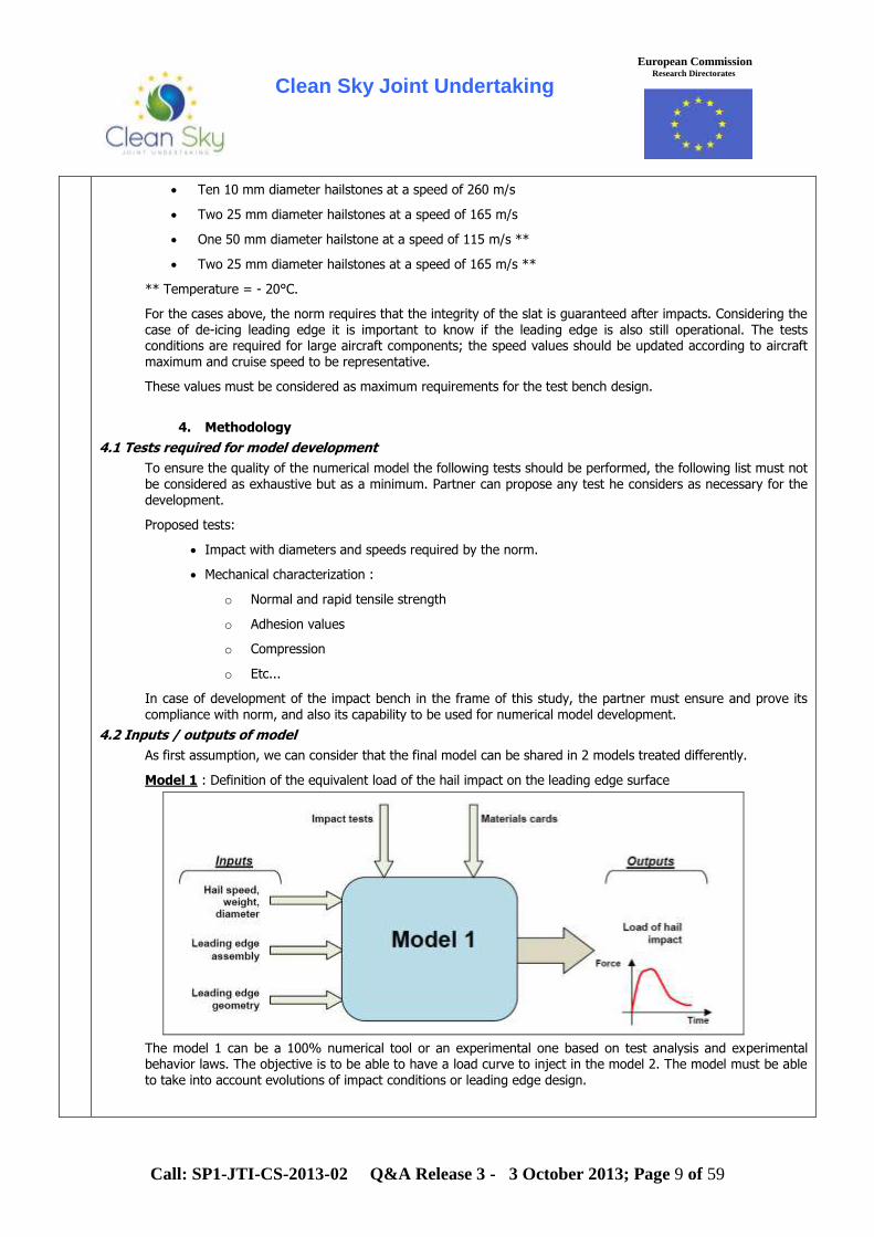
As first assumption, we can consider that the final model can be shared in 2 models treated differently.
Model 1 : Definition of the equivalent load of the hail impact on the leading edge surface
The model 1 can be a 100% numerical tool or an experimental one based on test analysis and experimental behavior laws. The objective is to be able to have a load curve to inject in the model 2. The model must be able to take into account evolutions of impact conditions or leading edge design.

Clean Sky Joint Undertaking
Call: SP1-JTI-CS-2013-02 Q&A Release 3 - 3 October 2013; Page 10 of 59
European Commission Research Directorates
Model 2 : Mechanical behavior of the leading edge during and after hail impact and consequences on leading edge structure and heater performance
The numerical modeling platform will be Ansys multiphysics or LS Dyna.
4.3 Development proposed main phases
Phase 1: Requirements specification of numerical model
1.1/ Bibliographic study: Norm and experiences relative to impact sizing
1.2/ Bibliographic study: Test means able to recreate impact characteristics with a capability of settings to allow variations of impacts used to develop and confirm numerical models
1.3/ Writing of both specifications: test bench (mechanical) and numerical tool
Phase 2 : Tools development
2.1/ Pre study of the impact test bench and numerical model
2.2/ Design and manufacturing of test bench (manufacturing may be subcontracted)
2.3/ First issue of numerical model
2.4/ Development of a test method
2.5/ Development of a control to compare the samples before and after impact tests
Phase 3: Preliminary validation of the tools
3.1/ Validation of the test bench: conformity of the impact with the specification (energy level, impact geometry, etc...).
3.2/ First comparison of real impacts and model results with simple composite structures.
3.3/ Update of the numerical tool according to first tests campaign.
Phase 4: Total tests plan and completion of the numerical tool
4.1/ test campaign with test bench on all the impact cases defined and on composite structure
representative of existing integration method (deicers included)
4.2/ Calculation campaign on all the test cases
4.3/ Completion of the numerical tool
Contents of phases 1 and 2 will be updated if impact bench is already available. For example manufacturing of bench can be replaced by an improvement of its performances.
5. Expected capabilities
Capabilities listed below are not necessarily internal and may be subcontracted or carried out by another partner.

Clean Sky Joint Undertaking
Call: SP1-JTI-CS-2013-02 Q&A Release 3 - 3 October 2013; Page 11 of 59
European Commission Research Directorates
5.1 Tests and analysis capabilities 5.1.2 Mechanical characterization
A complete characterization of the materials used for the leading edge is necessary at rapid and normal speed and at ambient temperature and at -20°C. These tests will allow to create material cards used in the models.
5.1.3 Hail impact
Existing hail impact test bench is an advantage, modification of another type of impact bench is also possible (armoring test bench for example). If this bench does not exist, the partner must have the capabilities to design; set up and use it. During impact test the following instrumentation will be used:
Rapid camera to visualize the behavior of the structure during impact
Stress sensors
Coupling of 2 rapid camera to allow 3D correlation to improve model development
5.1.3 Analysis
The composite structure samples will be analyzed after impact to define failure mode of the different layers. These failure modes will be used to improve model. This step will require composite knowledge and control equipment
5.2 Manufacturing capabilities
The samples used during development phases for impact or mechanical tests will be manufactured by the partner or its subcontractor or partner. These samples will be flat panel for the first tests and in shape for the tests used to know leading edge geometry impact. These panels should be simple assembly of plies with or without honey comb to be able to make test and to compare code and real results. Total representativeness is not required during code development, exact process and design will be necessary for final tests and validation step.
To manufacture these samples the partner will need to know simple thermo-set manufacturing knowledge with associated equipment (press and/or autoclave).
11
SGO-02-079 Optical Fibre based self-monitoring Motor Drives
Although the main activity relates to development of FBG sensors, which is our core activity, the topic description requires the development of a test setup: “The test setup will need to be able to provide for temperature/strain measurements for at least 1 duplex drive unit (2 motor units and 2 converter units), thus with a minimum of 16 interrogation channels. The motor drive performance requirements will be approximately 30kW @ 10krpm with an operating temperature range varying from -45 to 120 degC.” 1. Our question is whether the electrical drive components and power electronics on the setup will be provided by the
topic manager so that the developed full FBG system (including sensors, fibers, data acquisition equipment and related data management software) will be integrated on the provided testbed, or whether on the other hand the deliverable should include also the electrical drive components and power electronics in addition the full FBG monitoring system.
2. We would also like to know whether a set of specific requirements for the sensors and data acquisition equipment will be provided by the topic manager at the beginning of the activity.
1. The successful applicant will need to deliver a test setup able to load our motor-drive units as well as provide for temperature/strain measurements using both FBG systems as well as conventional sensor. Part of the requirements of the applicant will be to deliver a full FBG system ( incl. interrogation, data interface and sensors) and to work with the topic manager‟s organisation to integrate the fibres effectively into the power electronic and motor hardware which will be provided by the topic manager‟s organisation. The successful applicant has however to deliver a complete loading setup to include : FBG system, Conventional sensors, Data Logging for both, Loading Motor/PE test bench to drive the units under test.
2. Details about the sensors (eg. number of sensors on one fibre etc.) and data acquisition requirements will be
discussed and defined upon mutual consultation with the successful candidate, at the start of the project.

Clean Sky Joint Undertaking
Call: SP1-JTI-CS-2013-02 Q&A Release 3 - 3 October 2013; Page 12 of 59
European Commission Research Directorates
1. Please define further the paragraph “Be capable of loading the electrical drive to the desired power-speed ratings”. Does it mean that we must equip some electric motors with frequency convertors in order to adjust the rpm regime? Or do we have to send any signal to the electric drive in order to control the rpm regime? The quoted sentence refers to the fact that the supplied test bed would incorporate (i.e. within the scope of the bidder‟s supply) a load motor and its frequency convertor. This must also be interfaced to an HMI, how this is actually implemented can be discussed at a later stage
2. Concerning the duplex drive unit:
The motor units, will be supplied for the project? Are there more details about the motors to be applied? Which type of converters has to be applied? (Reduction gears, rotary to linear movement, torque, etc…) are they going to be supplied? The motor unit ( motor and convertor) to be tested will be supplied The motor will be for actuator purposes and will be of the rotary type With respect to gearing, it is up to the bidder to decide whether this is required. The motor under test must
be loaded up to 30kW at 10,000 rpm as specified in the Call.
3. Concerning the actuator drive system: Will it be supplied? Can we know more details about the actuator drive system?
Please refer to answers above
12
ECO-01-073 End of life assessment of Demonstrator B2 - Low weight green metallic fuselage panels" including physical dismantling and recycling
1. To which extent is the “Demonstrator B2” defined (measures, materials…).
2. To which extent is the “reference panel” end of life and the “Demonstrator B2” end of life defined?
3. Is the part already designed and manufactured, or manufacturing is needed.
4. Can we have access to more information about the previous project that ended with the definition of the so called “Demonstrator B2”.
1. There are two demonstrator fuselage panels to assess, with circular section, the length of each panel is roughly 1m, the arc of the circle isn‟t fixed yet (max 2.6m). The materials will be Aluminium magnesium lithium alloy, Magnesium E43, aluminium alloys (2050, 2198, 2099), few titanium Ti6-4 i.e. only metallic materials with associated surface treatments.Reference panel will have exactly the same geometry but with conventional alloys with CAA and chromate primer as protection. All assemblies are riveted with conventional rivets and sealants.
2. The reference panel has likely the same geometry as the topic manager demonstrator panel (one of the 2 panels).
3. The panels will be ready for the beginning of the project.
4. Information will be provided at negotiation phase.
13
SAGE-02-034 Health Monitoring - Wireless Sensors
1. Will the wireless sensor need to communicate in idle state? Or it has to communicate only when vibrations are
present?
2. How much percentage of the time will the wireless sensor be idle? E.g how many hours of wireless sensor
operation in a month are needed?
3. Please send us the minimum environment in term of vibration, temperature, pressure, strain similar with g vs.
Frequency [Hz] shown in the Call.
4. Is any data available over the piezoelectric behavior at the intended high temperature operation point?
5. What is the desired data rate of the wireless node?

Clean Sky Joint Undertaking
Call: SP1-JTI-CS-2013-02 Q&A Release 3 - 3 October 2013; Page 13 of 59
European Commission Research Directorates
6. What is the desired data range of the whole wireless sensor network?
7. Is there any desired MAC protocol or physical layer for the wireless sensor network?
8. What is the desired transmission range, in meters, of the wireless node?
9. How often will the wireless sensor node need to send the data? e.g Once every 10 seconds?
10. What the elements of the complete system are as mentioned in 1.F?
11. Is there a need for a hardware module (Super-node) which is acting as in interface between the wireless sensor
network and the FADEC via wire-line connection? This module will act like a data processing center: it will have
wireless transmitting & receiving capabilities to communicate/coordinate the wireless sensor network, and an
ARINC controller to interface with the FADEC. It will be powered via typical power lines.
12. Please send us the metallic environment used in the signal transmission.
13. Should the wireless sensor nodes have both transmitting and receiving capabilities? The answer will determine
the architecture of the wireless sensor networks. For example a wireless sensor nodes which have transmitting
capabilities only, will be autonomously powered and transmit data when vibrations are present, and it will go in
deep sleep mode when no vibrations are sensed. If the wireless sensor node has receiving capabilities too, then
it will able to react to specific commands coming from the Super-node and relay data to/from its neighbors in a
multi-hop fashion.
14. Which cells and batteries used for energy storage are desired and which ones are forbidden?
15. What is the area (size) and power output of a single piezo sensor which will be paired with the wireless sensor
node?
1. If the question is about engine idle state: It is requested to be able to communicate in engine idle state or when engine is off.
If the question is about sensor idle state: it is part of the project to define how sensors transmit their data. As written in the CFP, “Sensors can send data to an embedded receiver, to another sensor or to a ground receiver that can be approached to the sensor by an operator”. For example if this last case is chosen, then sensors shall communicate when they are in their idle state.
2. As an average, an aircraft engine is operated 10 hours per day, 300 days per year.
3. The minimum is when engine is off: no vibration and ambient conditions for temperature and pressure.
Each engine has its own vibration/temperature/pressure signature which also depends on the location of the sensor so it is impossible to answer by email.
If we can know what are the minimum level of vibration, pressure or temperature requested for the system, we will be able to identify where and when these requirements are reached on the engine.
4. Piezo-accelerometers typically works above 400°C
5. It is part of the project to define how often sensors data will be transmitted. The acquisition rough frequency is typically around the Hz for pressure or temperature and up to tens of kHz for dynamic strain.
6. The objective is 10 meters, the minimum is 6 meters.
Note: transmission is done in a metallic environment.
7. It is part of the project to define it.
8. The objective is 10 meters, the minimum is 6 meters.
Note: transmission is done in a metallic environment.
9. It is part of the project; it could be one time per flight (minimum) up to continuously pending the capability of the system and the architecture.
10. Sensor + local intelligence-CPU + data storage+energy supply & storage+ packaging + transmission.

Clean Sky Joint Undertaking
Call: SP1-JTI-CS-2013-02 Q&A Release 3 - 3 October 2013; Page 14 of 59
European Commission Research Directorates
11. It is part of the project to define the appropriate architecture to answer the needs.
12. Metallic environment and the way to estimate it will be debated between the selected partner and the project leader as it is complex and not possible to deal by email exchange.
13. It is part of the project to define the appropriate architecture to answer the needs.
14. Only batteries that could be certified for aeronautic applications (CS-E, CS-25) and which comply with maintenance requirements (no more than 1 maintenance action each 3 months for Line Replaceable Units or every 5 years for other equipment) can be used.
15. Energy harvesting location will be defined during the project .
14
GRA-01-052 Development and validation of methodologies and software tools for the implementation of accurate transfer of loads between numerical models
In the call, it is not clear what type of an optimization tool is being asked for weight reduction purposes.
1. Is it topology, shape or size optimization?
2. Is aerodynamic shape to be optimized as well?
1.The state of current practice is to perform originally topology optimization in order to define the overall optimized shape and then to apply size and shape optimization to finalize the optimization process. Therefore provision of combination of all above capabilities are required in order to ensure maximum benefit of optimization technologies. (Please see additional details on optimization demonstration, on deliverable A6).
2. Please see additional details on optimization demonstration, on deliverable A6. This is not a requirement for the purposes of this CFP, but provision of such capability would be considered advantageous during the proposal evaluation process.
15
SGO-02-052 Electrical Starter / Generator disconnect system
1. Should the shaft of the disconnect system be coaxial or can be parallel with main shaft of the aircraft engine?
2. Max. power to be transmitted by means of the disconnect system?
3. What are the characteristics of the electrical pulse for disconnection (AC, DC-PWM, time, power transmitted)?
1. There is no specific requirement regarding the output shaft being coaxial or parallel. However, in case of a non-coaxial output shaft, we would expect possible additional forces pushing on the generator inner shaft. If so these impacts will have to be analysed and compared to the benefits of a non-coaxial solution.
2) The max. torque to transmit is of ±400 Nm (depending the functioning motor or generator mode) with speeds up to 24,000 rpm, as specified in the document.
3) The electrical pulse is generated from a DC network. The minimum voltage supplied is 22 VDC, the maximum voltage 32 VDC. The target for the maximum current is 4 A.

Clean Sky Joint Undertaking
Call: SP1-JTI-CS-2013-02 Q&A Release 3 - 3 October 2013; Page 15 of 59
European Commission Research Directorates
16
ECO-01-072 Manufacturing optimisation of a plenum with GFRP cyanate ester-based prepreg
In the topic description it is mentioned that "...the budget of the project will include the cost for the prepreg material and fabrication of the positive mould to manufacture the demonstrator..."
1. Can you provide additional information regarding the selected cyanate ester prepreg? If the name of the prepreg cannot be disclosed at this stage could you provide an indication of the costs (for example price per Kg or per meter)?
2. Is it possible to provide an estimate quantity of prepreg required for the manufacturing of the plenum in order to properly budget for the material costs?
3. The mentioning of the positive tool suggests that the topic manager has already selected that the out-of-autoclave process will be similar to the autoclave one (vacuum bagging of single side tool). Can we suggest an alternate out-of-autoclave process?
4. Will the design of the positive mould be supplied by the topic manager? Or can we propose alternate designs for the tool?
1. Cost of the prepreg is approximately 30€/m2.
2. 12 m² are required to manufacture a plenum.
3. Yes.
4. Alternate designs for the tool can be proposed.
17
SGO-02-079 Optical Fibre based self-monitoring Motor Drives
1. Is the project funded as research (max 75% funding for academia/SME) or demonstrator (max 50% funding) or does
this depend on the content of the proposal?
2.The call shows hardware delivery at T0+18 months, but test, evaluation and reporting at T0+23 months. Please clarify
where the hardware is to be delivered to and whether the final 6 months work is to take place at the partner‟s or ITD‟s
site.
3. Are the prototype hardware deliverables from this project required beyond the end of the project? Over what
timescale?
4. Are specific measurands (e.g. torque, speed) required, or is the definition of measurands an outcome of deliverable
D1?
1. The funding rate is independent from the type of work in call for proposals. It depends only on the status of the applicant (75% for Academia/SME/research institute and 50% for others). However the funding would be only 50% if the applicant is already Associate in another ITD regardless their legal status.
2.The final hardware needs to be delivered to the topic manager‟s institution. The final 6 months of the project are
meant for data collection and parameter tuning of the test rig along with final report writing. Whether the work
carried out in those 6 months (in their entirety or part-thereof) be done at the topic manager‟s or the bidder‟s
location is subject to negotiation and progress. For example a factory acceptance test might be carried out in To+18
at the bidder‟s works (negotiated agreement) and further improvement found to be required. This can then be done
in the following months at the bidder‟s works, with the final delivery and commissioning to the topic manger‟s site
done within the allowed 6 month period.
3. As detailed in section 2 of the CFP the modular test bed will be delivered to the topic manager’s institution.
Such a setup will be available at the said location on permanent basis, for all clean sky partners to test their fibre-
enabled drives.
4. The specific measurands are desirable outcome of the project. Whether they can be achieved, or the associated risk

Clean Sky Joint Undertaking
Call: SP1-JTI-CS-2013-02 Q&A Release 3 - 3 October 2013; Page 16 of 59
European Commission Research Directorates
in achieving them should be outlined in the proposal document.
18
SAGE-02-032 Durability study of electrical insulating material in aircraft engine chemical environment
In topic description is stated that “this project aims to demonstrate the study of the durability of already selected thermosets in terms of electrical and insulating properties”.
1. Which are these “already selected thermosets”? Can we have the contact data of project coordinator who chosen these materials?
2. In order to characterize the behaviour of these thermosets in various chemical environments, who will provide us these materials? Or we have to manufacture these materials ourselves?
1. These already selected thermosets are typical epoxy and polyimide resins plus some other high Tg thermosets such as cyanate ester or high Tg silicone resins. Nevertheless, the project management remains very open to suggestions.
2. A financial provision to procure or manufacture the thermosets has to be integrated by the applicant of the CfP in the proposal.
Applicant can evaluate this provision based on a maximum of 8 different thermosets.
A support could be possible in certain cases by the project coordinator.
19
SGO-02-079 Optical Fibre based self-monitoring Motor Drives
We would like to have more details about the motor drive to be monitored:
1. Will this motor be part of an Auxiliary Power Unit? Of a thrust turbine? Of another system?
2. On what kind of aircraft such a motor will be integrated?
3. What kind of power will be supplied to it?
1. The motor drive under test is intended for an actuation system. This is however not restrictive to only one motor drive. It is one of the aim of the project to prepare a flexible test setup capable of excepting fibre-enabled drives within the power-speed envelop defined in the CFP document. The motor-drive to be monitored will be supplied by the institution of the topic manager.
2. A major deliverable of this CFP is a feasibility study on whether Fibre optic technology could be integrated in drives designed for aerospace applications ( having very high power densities). This work will target rotorcraft application; however the methodology and outcomes are expected to be transferable to other aircraft platforms.
3. Both Load machine and the motor under test will have their own Power electronic convertors. It is current opinion of topic manager that the load machine could be driven off a standard TPN supply whilst the MUT drive would either be supplied through a 270 Vdc bus or a TPN supply. In any case the latter PE convertor along with the MUT will be supplied by the institution of the topic manager. The applicant will need to provide for the load motor and drive.

Clean Sky Joint Undertaking
Call: SP1-JTI-CS-2013-02 Q&A Release 3 - 3 October 2013; Page 17 of 59
European Commission Research Directorates
20
SFWA-03-014 Vibration reduction systems in pylon area
Could you please specify the expected ranges for working and survival temperatures?
The applicant shall evaluate the performance of multiple technologies installed in different locations: a. Close to the excitation source b. On the transmission path (pylon structure) c. On typical interface: engine/pylon d. On typical interface: pylon/fuselage Therefore, a specific temperature range has to be defined area by area:
Area Working Temp Survival Temp Close to the excitation source 250°C < < 650°C* 650°C
On the transmission path (pylon) 55°C < <+50° 80°C On typical interface: engine/pylon
250°C Fire resistant
On typical interface: pylon/fuselage
15°C< < 30°C 80°C
*depending on the location
21
SGO-02-073 Numerical and experimental cross analysis methodology for mechanical impacts on a composite structure
1. How big will be samples to the experimental tests (mean size of the sample and how it looks like)?
2. Is there any obligation to monitor impact tests during the test and how the samples behave during the test or not?
3. What kind of deicers will be implemented on samples? Will the samples be delivered to the experimental tests by purchaser?
1. Exact dimensions of test samples have not been defined and should be determined according to test bench capabilities and to representativity regarding scale 1 structures (wings, slats, horns, etc...). Therefore there is no exact requirement regarding this point. Still, a reasonable order of magnitude could be around 30cm x 30cm, first in flat shape, then curved.
2. No accurate monitoring of samples during tests is necessary, but some global observation is expected, mainly using high speed camera (could be provided by TM). Test bench should offer compatibility with installation of such means. Any additional monitoring (sensors,...) is a good point but not mandatory. Everything should be considered regarding parallel analysis through experimental tests and numerical modelling (using inputs).
3. Deicers are electrothermal heaters composed of thin materials layers embedded in composite structures, often with metallic upper layer (erosion shield). All samples integrating deicers will be provided by Topic Managers and can be adapted to integrate specific interfaces (mounting solutions).
22
SGO-03-025 Automatic flight plan management tool for integration in bench of avionics equipment validation
1. What features should the graphical interface perform?
2. Who designs the visual aspect of the GUI?
3. Is there any platform or programming language limitation when developing the system?
4. Who defines the industrial protocol in Batch mode?
5. The edit and visual tool of the flight plans, will be integrated in the same GUI?
Clean Sky Joint Undertaking
Call: SP1-JTI-CS-2013-02 Q&A Release 3 - 3 October 2013; Page 18 of 59
European Commission Research Directorates
6. What values we have to show in the synthetic mode of flight plan visualization?
7. What values we have to show in the normal mode of flight plan visualization?
8. We need to specifically know the technical requirements of "current PC generation" expression.
1. The complete specification of the GUI will be defined and agreed during the first phases of the project. Here are some initial ideas :
Display: world map (countries borders, latitude, longitude, …), with data depending on selection: airports, flight plans (all flight plan data available, at least as tool tip). Capability to filter/unfilter flight plans according to different criterias. Selection of flight plan by pointer. Selected flight plan detailed data in a dedicated sub-window.
Current aircraft position in selected simulation with real time update (approx. every 1 second), if protocol allows it.
Research tools: depends on data fields in flight database. Multi criteria filter search (using 1 or more fields).
Flight plan manual creation: Graphically or from external file, using database airports, database points (from database flight plans). Created flight plan shall be saved in an external database and database tools shall be able to read external flight plan, external airports/waypoints. All external data would be provided in xml format (to be defined with potential cfp applicant).
2. GUI visual aspect are designed by potential CfP applicant, and reviewed by Cleansky SGO Topic Manager.
3. Execution platform shall be current PC generation, sharing processing resources with other regular applications under windows XP/7. Programming languages used shall be preferably Eclipse RCP environment, following could also be accepted: java/c/c++/ada95.
4. Industrial protocol in batch mode will be provided by Cleansky SGO Topic Manager.
5. Both display and edition and research tools shall be integrated in the same GUI.
6. Values shown in flight plan visualization synthetic mode depends on database fields (to be defined with potential CfP applicant).
7. Values shown in normal flight plan visualization depends on database fields (to be defined with potential CfP applicant).
8. PC minimum configuration : CPU Intel i3-2120 at 3.30GHz, RAM 4Gbytes, Hard drive: 1Tbytes, Windows XP or Seven.
23
SAGE-02-034 Health Monitoring - Wireless Sensors
1. Are commercial sensors valid sensors to be used?
2. Should we do a prototype for each measure? How many prototypes at least we must do?
3. The scenarios of each sensor are fixed, or we should take into account different scenarios? Is it possible to specify the concrete scenarios?
4. What is local intelligence exactly?
5. Time for each measure and number of measures each sensor have to be able to perform while running only with stored energy?
6. Minimum wireless network coverage?
7. Maximum distance between different sensors in line or outline of sight?
8. Is it necessary a coordinator sensor / gateway?
9. Which are the available frequencies or the best to be used in these type of scenarios?
10. Can be used existent wireless RF technologies solutions? (i.e.Zig-Bee)
11. The integration should be done only inside the project scope or also with other external systems?

Clean Sky Joint Undertaking
Call: SP1-JTI-CS-2013-02 Q&A Release 3 - 3 October 2013; Page 19 of 59
European Commission Research Directorates
12. Topic manager address and length of the meeting in order to correctly estimate the costs for the reviews?
13. Are there any security aspects for transmission?
1. Yes if the comply with the requirements.
2. A prototype is expected at the end of the project (deliverable D6), for SAGE2 (deliverable5) and each function listed from §1.A to§1.F must be prototyped (D4). It can be admitted to merge some prototypes of D4 if there is no risk to be unable to demonstrate a capability of the prototype because another capability does not work.
For example if you merge energy harvesting and sensor at high temperature in the same prototype, you must be sure a problem on energy harvesting will not affect the prototype availability to test high temperature sensor behavior.
3. Test scenarios are part of the project and will be debated between the partner and the project leader and the project leader.
4. It is a possibility to include a CPU into the sensor to resize data, resample, reduce data, etc. It is what is called “local intelligence”.
5. It impossible to answer this question as it depends on the energy used and its choice is part of the project. Wireless sensors must be able to run when the engine is ON but also when the engine is OFF and the aircraft ON.
6. see 7.
7. The objective is 10 meters, the minimum is 6 meters.
Note: transmission is done in a metallic environment.
8. It is part of the project to what is necessary to answer the needs.
9. It is part of the project to define the appropriate frequencies.
10. Yes if they answer the needs.
11. What is required is a system answering the need of the project;
12. Western Europe.
13. Transmission must be safe and secure. Security level will be debated between the partner and the project manager.
24
SAGE-02-034 Health Monitoring - Wireless Sensors
1. Propagation environment is very harsh. Assumption is that there is no radio channel model available for engine. Is it possible to carry out radio channel measurements to find out the radio signal propagation properties in a real environment, inside a helicopter‟s engine? Can be done, e.g., using vector network analyser - frequency response measurement.
2. Are interference levels measured close to engine, are there models available? Is it possible to measure those if models are not available?
3. Locations for sensor nodes and supernode? What is the degree of freedom in setting those positions?
4. Network topology, is it star or mesh? Is multi-hop routing allowed?
5. Impact of Doppler due to the vibration of engine?
6. Antenna requirements and design?
7. Coexistence and jamming/interference tolerance?
8. Transmitting measured information from sensors: send periodically (what interval?) or reported only when measured value changes?
1. It could be possible to make some measurements on an aircraft engine which does not run.
Note: the project is about aircraft engine.
2. No model is available.

Clean Sky Joint Undertaking
Call: SP1-JTI-CS-2013-02 Q&A Release 3 - 3 October 2013; Page 20 of 59
European Commission Research Directorates
3. It depends on the kind of measure: there are rotating and non rotating part. It will be discussed with the selected partner.
4. It is part of the project to define the best topology.
It must be noticed that the final application must be able to manage around 100 sensors. What is expected in this CFP is only to test several prototypes but the chosen architecture must be able (at least highlights no particular obstacle) to manage 100 sensors.
5. Not yet assessed..
6. The antenna(s) shall be compatible with an embedded system and associated certification rules.
7. Wireless sensors shall not disturb other embedded equipments.
8. It is part of the project to define how often sensors data will be transmitted. The acquisition rough frequency is typically around the Hz for pressure or temperature and up to tens of kHz for dynamic strain.
25
SAGE-02-034 Health Monitoring - Wireless Sensors
1. Is there any available results of any related study to this activity that can be disclosed ?
2. For each sensor, what is the measurement frequency (per s, per hour, per day., on the ground, in flight, before startup of engine, etc.)? Is there any requirement on the number of samplings per measurement (e.g. for averaging)?
3. What does "All treatments requested to extract embedded indicators (for instance sampling)" mean?
4. Does the topic manager provide access to test facility, to perform specific tests, such as Electromagnetic Interference certification rules as defined in DO160G, lightning effects as defined in ARP5416, vibration environment, etc.?
5. Is a battery (e.g. Lithium) allowed as local energy storage? What is meant by "cell"? Is it a disposable, non-rechargeable battery?
6. Who are the "partner" and the "project leader" in the sentence "The data transfer method will be selected jointly by the partner and the project leader during the project based on partner proposal."? We assume that partner is the author of the proposal and the project leader is the topic manager.
7. Can we get the "Details of metallic environment"?
8. It is written: "The maximum overall dimensions and installation constraints will be defined before the project kick-off." Can we have an order of magnitude of the typical available space and installation constraints?
9. Test support is required: how much time does the SAGE2 test will last?
1. No
2. It is part of the project to define how often sensors data will be transmitted. The acquisition rough frequency is typically around the Hz for pressure or temperature and up to tens of kHz for dynamic strain.
3. It is a possibility to include a CPU into the sensor to resize data, resample, calculate means, etc. What we call “local intelligence” is the ability to reduce data size.
4. No, but the way to prove the Electromagnetic compatibility will be discussed with the partner and adapted to lab/company possibilities.
It will be an advantage for partner selection to have its own test facilities and capability to test electromagnetic compatibility.
5. By “cell” is meant “battery”. Batteries are allowed if they answer all the needs (security even in harsh/hot environment and no more than 1 maintenance action each 3 months for Line Replaceable Units or each 5 years for other equipments).
6. The partner is the lab/company which is selected to realize the project whereas the project leader is the author of the topic in the CFP.
7. Metallic environment and the way to estimate it will be discussed with the selected partner as it is complex and not possible to deal by email exchange.
Note: It could be possible to make some measurements on an aircraft engine which does not run.

Clean Sky Joint Undertaking
Call: SP1-JTI-CS-2013-02 Q&A Release 3 - 3 October 2013; Page 21 of 59
European Commission Research Directorates
8. Available space and location will be defined with the selected partner as it depends on many factors like selected prototyped, the energy harvesting selected technology, etc. What candidates must have in mind is that space is limited on an engine and that some expected sensors are rotating so their mass & size must be limited.
9. What is required is a 6 months test support starting with the first SAGE2 tests.
26
SGO-02-066 HVDC fuses design, development, validation and integration
1- A DC voltage capability of a fuse has to be always linked to a L/R value. Can you precise L/R of the circuit ?
2 - Tests at 51,000 ft. As a mechanical device, altitude is impacted the fuse but from our "on-field" knowledge impact is limited to current rating variation. Nevertheless, will you request test validation of the fuse as component in a depressurized enclosure or will it be validated by Cleansky with the complete electrical system ?
3a - Handling a spike current needs to be clarified with a number of shots to withstand (average number of lightnings a plane would received during expected life time of the fuse)
3b - A current profile will be needed to clarify "within the range from 50 to 200A" as we assume 83A is the RMS value.
4 - A fuse melting time needs to be linked to a prospective fault current to clear and L/R of the fault circuit. Do you have such values ?
5a - Lifetime of a fuse is directly linked to current profile and number of cycles of such profile. Can you give those information ?
5b -Can you please clarify "long enough" : 1 week, 1 year, 10 year ?
6 - 200g: does it integrates holder or only fuse ? Is a melting indication function required ?
7a - What would be preferred design : cylindrical, cubic ?
7b - what would be preferred connections : holder to easier maintenance or directly integrated into the bars ?
8a - Should all environmental criteria of DO160 standards have to be tested ?
8b - As we assume electrical system will be enclosed; can you please give estimated operating temperature in the
envelop, min and max value ?
An electrical schematic of the involved circuit is always interesting to better understand surroundings.
1. L/R of the circuit is considered lower than 5 ms.
2. See answer of question 8. The aim is to do on the fuse itself all the tests which could impact its integrity or its functionnality.
3.a. The lightning level to be considered for the fuse are the worst : 1500V/15A and 500V/500A.
The lightning frequency is estimated to once each 3000 flight hours (approximately once every 7 month / 1 year), what makes around 50 lightning for each plane during its lifetime (30 years).
3.b. "Within the range from 50 to 200A" indicates the range of currents possible in this type of application, which can be covered by various calibers of fuses.
In this range, we consider particularly the value of 80A, corresponding to the current design in test. The 80A is the average DC value, with variation of current mainly between 30 to 90A. The fuse will be submitted to inrush currents of twice the average current.
4. The fault current is around 1000A to 2000A in stabilised short-circuit conditions. It reaches transiently high values due to the presence of capacitor in the circuit, e.g. peak 3,5 kA at 1 ms / peak 15 kA at 70 µs / peak 50 kA at 20 µs.
The requirement "The fuse melting time shall be lower than 3s at 300%*In, 10ms at 1000%*In" is a minimum performance in comparison to RCCB protection.
L/R of the fault circuit is considered lower than 5ms (refer to question 1).
5.a. Various loads will be connected to the fuse, with very different current profiles.
Two extrem ones where the load is a converter :
- doing start of a motor : high current close to overload during 60 s then stop.

Clean Sky Joint Undertaking
Call: SP1-JTI-CS-2013-02 Q&A Release 3 - 3 October 2013; Page 22 of 59
European Commission Research Directorates
- driving a fan in almost a constant way : current close to the average one.
5.b. "Long enough" means at least one year, but preferably around 10 years, in order not to require heavy maintenance.
6. The specified weight includes the holder. Melting indication function is not mandatory, but it is a "plus" if it doesn't affect the reliablity.
7.a. Design choice (cylindrical or cubic) is left free.
The main point is the global volume for the fuse implemented in the equipment (fuse + holders if any + connections).
E.g. of volume 100 mm x 20 mm x 40 mm in comparison with RCCB.
7.b. Connections shall be ensured by holders, or other system allowing rapid change with standard tool, in order to ease the maintenance operations. No soldered connection.
8.a. Applicable environmental criterias and associated levels are specified in the next table "DO160G".
Refer to question 2 : The aim is that the fuse is submitted to all the possibly critical tests. It is possible to justify some requirements by analysis or simularity, if data exist on the subject.
8.b. The stabilized environment temperature for the fuse in operation is in the range mini -40°C / maxi 130°C (short time), and may reach 95°C for long period (several hours). The fuse is connected to bar; the stabilized bars temperature may reach 125°C, with up to 5min transient at 150°C.
The fuse not operational shall not be degraded by "survival" temperatures in the range [-50°C; 150°C].

Clean Sky Joint Undertaking
Call: SP1-JTI-CS-2013-02 Q&A Release 3 - 3 October 2013; Page 23 of 59
European Commission Research Directorates
27
SFWA-03-014 Vibration reduction systems in pylon area
1. In the description of work section point b, the environmental conditions are cited a constraint for the design. Is it possible to have more information on those environmental conditions?
2. In the description of work section point e, is it possible to further specify the tests (especially the ageing test)? What are the conditions expected for the test?
3. Regarding the demonstrator (deliverable) , should it be tested in a real engine or in a laboratory scale test bench developed for reproducing the conditions? If a test bench is expected, should this development be included in the project or is already available from previous work being provided by the topic manager?
1. Envelope of typical aircraft in service environmental conditions and engine operation conditions.
2. Typical aircraft and engine in service conditions (cf previously) coupled to average cycling sollicitation (depending on engine levels).
3. The demonstrator itself should be tested on a bench in the frame of this CFP (mechanical, temperature,...tests) as far as it could be (but without engine) and the test bench should be developed in the project if the typical mechanical, temperature,...test required needs dedicated and particular (not already existing) test bench. If the demonstrator gives convincing results, the solution will be implemented for the FTD, on real aircraft conditions with the engine and the pylon, but this is out of scope of this call.
28
SGO-02-079 Optical Fibre based self-monitoring Motor Drives
1. Please define further the paragraph “Be capable of loading the electrical drive to the desired power-speed ratings”. Does it mean that we must equip some electric motors with frequency convertors in order to adjust the rpm regime? Or do we have to send any signal to the electric drive in order to control the rpm regime?.
2. Concerning the duplex drive unit:
The motor units, will be supplied for the project?. Are there more details about the motors to be applied?.
Which type of converters have to be applied? (reduction gears, rotary to linear movement, torque, etc…) are they going to be supplied?.
3. Concerning the actuator drive system:
Will it be supplied?. Can we know more details about the actuator drive system?
1. The quoted sentence refers to the fact that the supplied test bed would incorporate ( i.e. within the scope of the bidder‟s supply) a load motor and its frequency convertor. This must also be interfaced to an HMI, how this is actually implemented can be discussed at a later stage.
2.
• The motor unit ( motor and convertor) to be tested will be supplied
• The motor will be for actuator purposes and will be of the rotary type
• With respect to gearing, it is up to the bidder to decide whether this is required.. the motor under test must be loaded up to 30kW at 10000rpm as specified in the Call.
3. Please refer to answers above.
29
SGO-02-078 Ice Phobic Coating Associated to Low Power Electromechanical Deicers
1. Are there more detailed specifications that would help us evaluate the performance of the ice phobic coating?
2. In the last point of the chapter 3 “Type of work” of the CfP it is written: “Use laboratory test facilities for measuring ice adhesion forces in several environmental conditions”.
a. Which kind of test bench should be used?

Clean Sky Joint Undertaking
Call: SP1-JTI-CS-2013-02 Q&A Release 3 - 3 October 2013; Page 24 of 59
European Commission Research Directorates
b. To which “several environmental conditions” do you refer to?
3. According to the CfP, the erosion shield is metallic. Of which kind of metal is made? Is the surface of this metal treated with other coatings?
1. A document will be only available to the winner during final contract negociations. It lists regulation and standard documents, for performances and environmental, integration requirements and demonstrator definition.
2.
a. Climatic chamber with thermal range from -40°C to 0°C could be used.
b. Atmospheric Icing Conditions as defined in FAR 25 Appendix C, temperature, droplet size or water content.
3. The erosion shield is made of Aluminum 2024 T3 or equivalent.
30
GRA-01-052 Development and validation of methodologies and software tools for the implementation of accurate transfer of loads between numerical models
1. In chapter 6 of the proposal, you mentioned that a CAD model will be given.
Is it possible to have already some details on the geometry?
Profile type, number of ribs, ribs geometry, chord and span length?
For the wind tunnel testing, the model has to be scaled, so we would like to know which will be the final dimensions after the scaling.
Depending on the level of miniaturization of the final model, we will need to select an adequate type of wind tunnel (costs will be different).
2. When you mention testing in a subsonic wind tunnel, which Mach number is associated?
We could test between Mach 0.3 and 0.9. Which is a reasonable target?
3. Is there a minimum number of tests to be performed?
How many angles of attack, how many Mach numbers?
4. For the wind tunnel testing, only the strains in the ribs have to be measured as a validation of the CFD/FEM approach, right?
When you mentioned that the wing has to be analyzed both aerodynamically and structurally, does this mean that also aerodynamic coefficient (lift, drag, moment) of the wing has to be measured?
5. Knowing the pressure field around the wing is not sufficient to determine the aerodynamic loads, therefore balance measurements are also necessary.
Could you please clarify this?
1. It is not possible to provide such detail information at this stage due to confidentiality reasons. Additionally the final geometry of the test article is expected to be shaped upon completion of the sizing study to be performed by the applicant. As a general guidance for cost evaluation purposes you should assume a chord to span ratio ranging from 0.25 to 4 for a span of the physical model not exceeding 4 meters. The limiting length of the final dimensions of the test article is mentioned in the proposal as not exceeding a span of 2 meters. As far as concerns chapter 6 of the proposal, models to be provided are intended for the numerical justification case (see section 5 B.1) and not for the test article. Detailed information on the process to be followed regarding definition of the geometrical characteristics of the test article is given in section C1. As a general guidance regarding scaling of the test article, the applicant should account for an upper limit of Reynold‟s number in the order of 1500000.
2. The above range is expected to be hugh for the purposes of the present project. It should be noticed that in order to limit the cost of manufacturing and wind tunnel testing for the test article, it is expected to limit the test to a maximum speed of Μach 0,2.
3. : It has to be mentioned that the purpose of the test is not to characterize the properties of an aerofoil section (i.e. α versus CL curve), but to verify CFD analysis loads and FE analysis results based on that loads. Therefore the number of tests to be preformed is expected to be considerably less than that. As a guidance the total number of

Clean Sky Joint Undertaking
Call: SP1-JTI-CS-2013-02 Q&A Release 3 - 3 October 2013; Page 25 of 59
European Commission Research Directorates
runs- combinations of test angle of attack and speed - is not expected to exceed a number of 25 cases.
4. Strains in the test article are needed to be measured in order to be able to verify the load transfer accuracy both in a local but a global level. Therefore strains gages should not be limited only to ribs but also to the root of wing spars and under the skin at various locations. Actual positions and numbers to be determined after performing an FE analysis by the applicant, of the model of the test article. A number not exceeding 50 channels (direct and shear stresses) is expected to be sufficient. It is important to be noticed that the wing section to be tested should resemble a real aircraft structure and not be a specific wind tunnel model for measuring only pressure distribution and reactions at the scale of the wind tunnel.
5. This is correct, it will be necessary to be able to measure via a load measuring device the aerodynamic loads developed in the test article in order to be able to verify global resultants (such as lift, drag and pitching moment)
31
SGO-02-079 Optical Fibre based self-monitoring Motor Drives
1. We will have to agree about the test drive specifications with the topic manager, then develop a testbench to monitor it and finally send the testbench to monitor an aerospace drive. Is that correct?
2. What is the kind of implication expected in the final performance review task: shall we operate the testbench ourselves or provide support to the topic manager operating it?
3. Can we have some precision about the location of the plant where the test bench shall be delivered?
1. The successful bidder will have to liaise with the topic manager to define the Motor to be tested specifications. This will be provided by the topic manager. The bidder will then use this initial Motor Under Test ( test drive) to develop a test bench capable of accepting similarly rated machines.
2. The test bench will be commissioned by the bidder, using the motor under test provided by the topic manager.
Training in using the relevant software and operation procedures shall be give to the topic managers staff for further use and testing of other fibre enabled drives.
3. The test bench shall be delivered to the topic manager‟s institution.
32
ECO-01-072 Manufacturing optimisation of a plenum with GFRP cyanate ester-based prepreg
In the text of the call it is mentioned that the nature of the prepeg, the processing materials and parameters will be provided by the project manager at the beginning of the project. There is no reference to the mould.
In our proposal we have included the manufacturing of a mould (two moulds to produce the described prototype).
We were wondering if it necessary to include the manufacturing of the moulds on the proposal or shall they be provided by the project manager.
Information related to the current process will be provided by the topic manager to the applicant at the beginning of the project. These informations included nature of the prepreg, the processing materials and parameters.The manufacturing of the mould(s) has to be included in the proposal, but its design could be modified during the project according to the knowledge of the topic manager, in collaboration with applicant.
33
GRA-01-052 Development and validation of methodologies and software tools for the implementation of accurate transfer of loads between numerical models
1. Which is the FEA code already in use by the Topic Manager?
2. Regarding C1 point, the wind tunnel infrastructure is available from the Topic Manager or should be allocated by the applicant? In this sense, the expected tests have to be acquired by the applicant alone or in collaboration with the Topic Manager?
1. The FEA code in use is MCS/NASTRAN r2012.
2. The wind tunnel infrastructure is expected to be provided by the applicant, which in turn has to perform all the required tests. Topic manager may request to be present at some of the tests for informative purposes. Please also refer

Clean Sky Joint Undertaking
Call: SP1-JTI-CS-2013-02 Q&A Release 3 - 3 October 2013; Page 26 of 59
European Commission Research Directorates
to a reply to a similar question below.
It is clearly stated within the proposal (Section C) that the experimental validation part of the project will be performed by the applicant and not the topic manager or being provided from other party. This includes aerodynamic analysis and structural design of the wing section as well as manufacturing and instrumentation with static pressure probes and strain gages that will enable the verification of the numerical results. Furthermore he will be responsible for the wind tunnel test, interpretation and possible calibration of the results, in order to develop a methodology that enables minimization of the error introduced during load application of CFD results to the global FEA model.
34
ECO-01-073 End of life assessment of Demonstrator B2 - Low weight green metallic fuselage panels" including physical dismantling and recycling
We intend to submit a proposal for the above stated topic and we would like to ask for details of the composition of the “B2” demonstrator . Please confirm whether this panel has any magnesium alloy component that should be considered and finally may you please provide the references of the Al alloys used to build it, i.e. are only Al-Li alloys used or there are also Al-Cu or other Al series to be considered?
The materials to be considered are:
• Aluminum magnesium lithium alloy (AlMgLi), magnesium E43, 2050, 2198, 2099, few titanium Ti6-4 i.e. only metallic materials with associated surface treatments.
• Reference panel will have exactly the same geometry but with conventional alloys 2024, 7075 with CAA and chromate primer as protection.
• All assemblies are riveted with conventional rivets and sealants.
35
SAGE-02-035 Non-rigid geometry variation simulation for fabricated aero engine structures
The topic description includes as one of its tasks (in particular, task 4), the "manufacturing of component geometry and fixtures to be used in the demonstration of a weld assembly of a simplified complex geometry componen consisting of several rigid and flexible sub parts".
It is clear that all the cost related to the manufacturing of the simplified component geometry and fixtures must be included in the budget of our proposal.
Are the raw materials which must be used for the manufacturing included (basically, nickel based precipitation hardening superalloys)?
Are these raw materials supplied by the topic manager? Maybe, to obtain a low quantity of these materials to manufacture a small sample will not be easy at all (neither cheap).
The raw material is not supplied by the topic manager.
36
GRA-01-052 Development and validation of methodologies and software tools for the implementation of accurate transfer of loads between numerical models
The question is regarding the Activity description part, namely A6.
There is a sentence:
Development of an optimization code that can be linked with a pre-existing FEA solver (NASTRAN) or CAD as 3DS CATIA in order to control the geometrical parameters affecting generated mesh.
Does it means that the optimization code should be focused on optimizing a mesh (e.g. optimization of the mesh in the leading edge region to obtain sufficient accuracy for the loads transfer between CFD and FEM solwers)? Or is it intended to optimize the structure of the wing by other FEM software than NASTRAN in connection with CFD?
The objective of this requirement is the capability to optimize a subject structure in order to minimize certain design parameters such its weight or displacement. In a first approach this would consider a given external aerodynamic geometry and global loads and the optimizer should be able provide an optimal solution in terms of weight of the

Clean Sky Joint Undertaking
Call: SP1-JTI-CS-2013-02 Q&A Release 3 - 3 October 2013; Page 27 of 59
European Commission Research Directorates
structure. For that purpose, a subject structure such as a wing rib is required to demonstrate the optimization capabilities of the code.
In addition to that, the code to be provided should be independent of the optimization capabilities of the FEA code the TM is currently using i.e. SOL 200 of NASTRAN. NASTRAN should be certainly used as the solver with its other solution sequences. The ability to be able to use other FEA solver should be subject to customization of the optimizer (by selecting for example another type of input data file) but not required to be provided.
If now the capability to cooperate with a CFD code in order to overall minimize the weight by modifying the structure by the external shape, as well as the error during the load transfer between CFD and FEA, this would be considered as an advantage in the evaluation process.
37
SGO-02-079 Optical Fibre based self-monitoring Motor Drives
1. In the call for proposals a minimum of 16 interrogating channels are requested. Does it mean that 16 measuring
points are needed or literally 16 different interrogating fiber channels are foreseen? Multiplexing is an accepted possibility?
2. According to the call 1 duplex drive unit (2 motor units and 2 converter units) are intended to be tested and the test set up needs to provide temperature and strain measurements to the duplex drive unit. The test duplex drive unit is out of the scope of the budget of the call? Is the topic manager supplying the duplex test drive? Is it possible to have more information about the test duplex drive or it needs to be worked during the first stage of the project?
3. The duplex test unit is composed by two motors. Are both motors going to be tested in the test set up controlled independently? Or, Can one of the motors be used as a brake to the other one, in a back to back configuration?
4. Temperature and strain sensors, either conventional technology or fiber based technology are supposed to be installed in the stator of the test drive units?
1. 16 interrogation channels are foreseen, the amount of measured points per fiber has to be seen as a function of spatial resolution required. This will be discussed with the topic manger during negotiation.
2. The duplex drive unit will be defined during the negotiation period and supplied by the topic manger.
3. The idea of duplex drive comes about from the required final application reliability issues and redundancy requirements. For the scope of the project they have to be considered as one machine under test.
4. Both technologies should be installed to verify the fiber measurements.
38
SAGE-01-002 Fracture mechanic investigation of a new high temperature Ni-based casting alloy
1. Is the raw material included in the Project? Without cost? Or what would be it cost?
2. What is the shape in which the raw material is supplied? Powers or plates? If it is in the form of plates, what would be its dimensions?
3. What would be the dimensions of the cast test plates that shall be hot isostatically pressed?
4. What would be the conditions of the HIP process? Temperature and pressure?
5. What would be the size and dimensions of the different mechanical test samples?
6. Which standards will be used to perform the mechanical tests?
1. Should be included in costs, estimated cost approx. 75 k€
2. Plates. Approximate size range: width 100x length 200x thickness 16-20 mm
3. See above
4. 1100-1200°C, 100 bar, 2-5 hours
5. They should be possible to machine from the size of blanks/plates described above and they should conform to the requirements in the standards exemplified below.
6. ASTM standards for the type of testing described in the call text, e.g. standards like ASTM E102, ASTM E466, ASTM

Clean Sky Joint Undertaking
Call: SP1-JTI-CS-2013-02 Q&A Release 3 - 3 October 2013; Page 28 of 59
European Commission Research Directorates
E606, ASTM E647
39
GRA-01-054 Flexible sensor co-operation for structural health diagnosis/prognosis
1.The design and manufacturing of sensors is considered in the CfP in order to assess the proposed detection methods, however, which is the technology readiness level expected in the sense of size, weight, electronic miniaturization and others?
2. Which kind of structural failures are prioritized?
3. Which installation procedure of the sensors is expected in the sense of attachment to the structure?
4. A continuous monitoring is expected?
5. Are the representative specimens of the defined scenarios provided by the CfP leader?
6. Is there a preferred option for the development of the hardware platform needed to centralize the sensor‟s array information and processing?
1. The sensors themselves (design, miniaturization, weight …) are not the goal of the CfP. It is the application of sensors characteristics, measurement capabilities, reliability etc to the damage detection and evolution control feasibility what becomes the main objective of the CfP. In this context, feasibility of different sensors data fusion to discriminate and read across multiple type of signals should become a principle.
2. Assessment of damage, detection of impact, measurement of damage evolution (expected mainly associated to delamination on composite structures)
3. Anyone could become feasible to get the goal. Alternatives for practical integration into the structure could be assessed meanwhile CfP is running
4. Although the concept should be inherent to the final version of the system meanwhile active. During development the monitoring should be constrained to events or test phases decided on purpose
5. Yes, alternative scenarios to be agreed with the applicant based on own resources if it could be proved more effective
6. During the feasibility phase is open to the applicant proposal.
Further aspects to be discussed during negotiation phase.
40
GRA-01-055 Development of novel inspection approaches and automated systems for monitoring CFRP damages on-line
1. Can the range of lengths, widths, and thicknesses of the subcomponent be specified? What type and kind of panels (flat, curved, monolithic,…)? What size? Unilateral access or not ? ) How big is the envisioned fuselage cockpit? assuming that the cockpit will be provided by the ITD partner? The answer is needed, because subcomponent size (such as a CFRP panel) may affect the budget of the proposal. 2. Which of the following flaws or defects are expected to be detected during the test? (a) delaminations, (b) porosity, (c) foreign materials, (d) thickness variations, (e) bending deflections, (f) fiber failure, (g) superficial damage and/or, (h) component failure and end of test. What are the expected sizes and/or depths of the flaws? And What are the expected critical sizes? 3. (i) What is expected to be monitored? (a) The initial appearance of a defect, (b) position of the flaw (c) flaw evolution and/or (d) the distribution evolution of a particular defect where comparison patterns are needed to then take a decision, etc.. (ii) Are there any standards to be followed during the detection of flaws and defects? Which standards?
4. Will the test rigs be used for a static test or variable load test? Will the test rigs always be in contact with the place of the test specimen where surface damage might appear? What space will be left between the test rigs and the specimen? 5. a) If the Non Destructive Test (NDT) system is expected to travel, then what area should be covered during the test and, in how much time? b) If the NDT system is not expected to travel can the test rig be used as support for the NDT system? 6. Can a coupling agent such as water, oil, glycerin or others be used over the specimen? 7. Can the acquisition requirements and data recorder system specifications be specified? Which type of communication protocols will the final customer /consortium need? (a) EthCat, (b) RS485, (c) Profibus and/or (d) others? Which of the following data formats are expected from the chosen NDT technology? (a) Raw data, (b) processed data, (c) interchangeable files and/or (d) other data types.

Clean Sky Joint Undertaking
Call: SP1-JTI-CS-2013-02 Q&A Release 3 - 3 October 2013; Page 29 of 59
European Commission Research Directorates
8. What type of recording system will the final customer/consortium need? (a) SCADA, (b) BBDD or (c) other. Should this recording system work with analogue signals or others? 9. Can the platform requirements of the user interface and web system be specified? Requirements such as user access system, protocols for data transfer, etc.. Can the language or languages of the web system be specified? 10. To plan the verification the NDT system, several details need to be specified. What type of mechanical test will be performed? How many tests are expected to be monitored? 11. In the final report specifications, how should the results types be presented? 12. In the final report specifications, what will the validation criteria be? (a) Pass/Fail, (b) specified algorithms or (c) others. 13. Where is the NDT system expected to be developed, verified, tested and finally installed? 14. When the project finishes, who owns and keeps the NDT system developed? 15. Are the concerned areas predetermined by human or this determination is also a part of the automated procedure? 16. What kind of mechanical and NDT tests are currently involved? 17. "Once the technological aspects have been proved at basic level in isolated manner, integration into a compact solution will be tackled to understand the degree of complexity and other interface problems". What do you mean by basic level in isolated manner? 18. What are your degrees of acceptance regarding repeatability and reproducibility? 19. Size of the field of view of the inspection system? 20. Access to data characterising the damage (i.e: damage surface): which kind of defects are wished to be detected? Which size of defects should be detected? Should the defects be detected on the skin of the panel and/or inside the panel? 21. Speed of the inspection. For example, for how long can a CFRP panel of 1m² be inspected? 22. Duration of the measurements without re-calibration? 23. Do the required monitoring system specifications describe a static system or should it be part of a robotic system with autonomous movement? 24. Which TRL is supposed to have the NDT demonstrator? 25. In the chapter Special Skills, certification or equipment expected from the applicant CATIA is not required. However, in the deliverable D-08 “General Design of whole system (CDR)” it is supposed to deliver the design in CATIA. Is it possible to use another design software like SolidWorks? 26. What type of mechanical testing needs to be performed? These tests will be defined and executed by the ITD or by the applicant? 27. Special Skills, certification or equipment expected from the applicant. The selected applicant should demonstrate general experience in several areas: How do you demonstrate the experience in a particular field? It is mandatory to have previous experience in similar projects or having an expert in that particular field is enough? 28. The topic states: “the systems should be able of performing automatic NDT on specified areas of certain structure“ The complex shape of the structure and all-surface accessibility for the system are critical aspects in the NDT process? 29. Which are the approximate dimensions of the final structures susceptible of being inspected by the system? 30. In case of application of ultrasonic solutions for the NDT, is it possible to use couplants (i.e. water jet coupling solutions) to facilitate the transmission of sound energy between the transducer and the test piece? 31. The topic states: “to develop a system to perform NDT during test execution in an automated manner and transmission of the results on-line” Does the system include in the scope the automatic diagnostics of the test results? 32. Which kind of failures/defects are prioritized? Are the acceptance criteria already defined? 33. Are the representative materials, samples, reference blocks, specimens… provided by the contractor? 34. The topic states: “to develop a system to perform NDT during test execution”. NDT and tests will be always executed simultaneously or some tests can be temporarily stopped during the inspection to alternate both actions? 35. There are previously executed projects related to this topic whose results are relevant for this project?
1. For the purpose of the research being performed, • The concerned areas of inspections should be limited to controlled impact damage size and surrounding areas either on panels (flat or curved) or overall cockpit at several locations • Skin thickness range should be between 1,5 and 3 mm, (design details as ramps to adapt thickness changes should be observed) • At co-bonded structure areas (stringer foot) total thickness could be in the range of 3 to 5 mm,(changes in skin thickness impacting substructure should be accounted) The main interest is on solid laminates although system can be checked on the skin of sandwich structure (in the order of 1mm) with (in the order of) 20 mm core. Subcomponent subjected to mechanical testing: Flat monolithic & sandwich panels 600mm x 600mm. Access both sides Component: Curved monolithic panels, flat or quasi-flat sandwich panels, for size see (27). Access one side while testing and both sides if test is stopped for detail and deep NDT

Clean Sky Joint Undertaking
Call: SP1-JTI-CS-2013-02 Q&A Release 3 - 3 October 2013; Page 30 of 59
European Commission Research Directorates
For quantification purposes 3000 mm of diameter and 6000 mm length (typical cockpit shape end-up with a quasi-flat forward pressure bulkhead. The rear pressure is part of the test rig. Inspection of the full cockpit meanwhile testing is not the target. 2. The type of defect is mainly focused to delaminations and fiber breakage and those aspects related with impact damage (delamitations or unbonding defects induced during manufacturing should be covered). See (28) for more details. The size of the flaws will be those resulting from impact damage. Critical sizes are expected to be a few times the area involved in a impact damage, although this is not fully determined at the current state. Different locations and structural configurations together with different energy levels should induce different damage types and sizes. 3. (i) Evolution of artificial defect/damage meanwhile testing as far the structure becomes accessible. (ii) No standards, just results from impact damage or equivalent manufacturing defects. 4. It is foreseen both static and fatigue testing. The test rig should not be in contact with the damage/defect location being monitored. NDT probe contact is not allowed meanwhile testing. Several times the damage size, to enable measurement of the damage evolution. 5. a) Enough to account for local damage/defect extension at all the locations where damage or defect have been artificially induced. Use as reference current inspection techniques. b) NDT system should care of self support devices, although test rig could account for platforms to enable access to external surface meanwhile testing. 6. Before the test, meanwhile ordinary quality inspection or to take reference for data base, use of coupling agents might be used. Afterwards and meanwhile testing No, the specimen cannot be coupled with any agent but surrounding air, in fact the inspection probe cannot touch the structural specimen. 7. It is expected the data could be recorded and treated by standard commercial software (i.e Microsoft or similar), the objective is focused on the technological feasibility other aspects are secondary for the time being. Any format as far it can be processed and used together with a reference to interpret and monitor damage evolution At this state, no specific constraint as far other aspects might be observed. Open to more detailed discussion into negotiation phase. 8. At this state, no specific constraint as far other aspects (see 7) might be observed. Open to more detailed discussion into negotiation phase. It is not foreseen any recording of analogue signals. 9. In principle, protocols should not be a constraint as far the system could transfer data wireless between correspondent systems own units. Language and protocols are expected to be compatible with usual wifi routers used for commercial computers communications. 10. Under the scope of flat panels, shear or tension and compression testing. Curved panels are foreseen being checked during full cockpit testing although some panels might be available out of mechanical testing for system tuning purposes. Two type of mechanical tests both static & fatigue, one at subcomponent level (panel) and one at component level (cockpit) 11. No restriction, as far as the evolution of damage is correctly evaluated. 12. Comparison with results of existing qualified NDT systems. Eventually if decided, through destructive testing of the damaged area. 13. Development is a matter of the applicant, verification and validation it is foreseen at ITD test installations or prescribed laboratories where subcomponent or component testing is being carried out. 14. The hardware custody should be responsibility of the applicant accomplishing foreseen Clean Sky rules in terms of IP for dissemination aspects. As stated in the rules, the foreground generated is property of the Partner; however, in the IA details on the access rights and further use of the HW must be detailed and agreed, during negotiation. 15. The concerned areas (critical locations) can be considered predetermined and they should come from: • artificial manufacturing damages or defects • artificial impact damages (low energy compatible with design criteria) • locations identified by analysis where local failures might occur (i.e disbonding) • local failures observed during testing 16. Foreseen mechanical testing: • In plane shear, tension & compression • Out of plane (pressure) (only for full cockpit) NDT currently involved: Ultrasonic scan. 17. Feasibility of the technology does not need full integration in a compact device of all the subsystems being handled, this could be done at a later state. 18. Same as standard ultrasonic systems currently in use for NDT for the level of defect and damages types and sizes being monitored. 19. Directly related to the damage size. 20. The type of defect is mainly focused to delaminations and fiber breakage and those aspects related with impact damage (delamitations or unbonding defects induced during manufacturing should be covered). See (2) for more details. 21. It is not primarily intended NDT of the whole panel but mainly monitoring locations where damage or defect could

Clean Sky Joint Undertaking
Call: SP1-JTI-CS-2013-02 Q&A Release 3 - 3 October 2013; Page 31 of 59
European Commission Research Directorates
have been artificially induced. Secondarily, other NDT scenarios might be convened as it became convenient. Quick enough to enable control of local damage evolution meanwhile fatigue testing (foreseen between 1 to 10 load cycles/sec depending on type & size of structure from coupons to major). 22. No recalibration is foreseen during the monitoring of a local damage/defect evolution. 23. As far as the technological feasibility might be substantiated the autonomous movements into a robotic system does not become mandatory at first state although the dependence of human during inspection and damage/defect evolution assessment should be minimized. 24. It is expected to be above TRL3 to be checked during the cockpit demonstrator testing. 25. As far as design interfaces with CfP launcher might be transferred from/into CATIA as it became required, there is not constraint in using alternative software to make the design. What is mandatory is the capability to exchange data in CATIA format. 26. - At subcomponent level Flat panels (basic / stiffened) and component level for verification purposes, static & fatigue testing by the ITD - Other testing to show technology feasibility is responsibility of the applicant. 27. The applicant experience should be demonstrated through NDT projects carried out in the past with TRL3 or higher. The project leader and other team members have to declare evidences of knowledge and skills in the technologies being considered. 28. The structure is typical a/c cockpit configuration (smooth double curvature) generated using CATIA models from which a virtual mock-up could be handled. As an hybrid structure overlapping areas of different materials might be susceptible of inspection depending on criticality. Accessibility to external surface is guaranteed. 29. At subcomponent level, typical flat panels in the range of 600 x 600 mm2 A component level cockpit of 3000 mm diameter x 6000 mm length. 30. Before the test, meanwhile ordinary quality inspection or to take reference for data base, use of coupling agents might be used. Afterwards and meanwhile testing No, the specimen cannot be coupled with any agent but surrounding air, in fact the inspection probe cannot touch the structural specimen. 31. Diagnosis is a matter of test results assessment that can be done after transmission of data into a system unit different than heading probe. 32. Typically those coming from impact damage. Different locations and structural configurations together with different energy levels should induce different damage types and sizes. 33. As far as the technical reliability has been proved the contractor will provide samples or accessibility to subcomponent to enable technology adjustment for the structure being inspected. 34. The main goal of the required system is to enable inspection meanwhile testing is being carried. This does not mean that some testing might take place following standard approaches (in absence of mechanical testing). In fact “Zero” Load is a particular NDT condition. 35. The applicant experience should be demonstrated through NDT projects carried out in the past with TRL3 or higher. The project leader and other team members have to declare evidences of knowledge and skills in the technologies being considered.
41
SGO-02-082 Lithium-ion energy storage module for Integrated 28Vdc Modular Power system
During the call for tender explanation it is said that the duration will be of 20 months but in other part it is said that the activities shall be limited to 18 months' time, what would the correct period be?
The duration of the project is 20 months
42
SAGE-06-003 Development of materials, processes, and means to enable the application of piezoelectric materials in aero engine controls.
1. A similar topic was opened at CS Call 13 but it was allocated to SAGE03. At the present call the topic is addressed to SAGE06. The SAGE requirements are different, how does this affect piezoelectric devices? How does this change the requirements for the piezoelectric sensors and control functions? 2. The TRL of the topic is not defined at the call, please, could you give us an idea about the TRL proposed by the Topic Manager. At the Brussels 16/07/2013 presentation, the following was mentioned: “Materials and processes identification, development, and laboratory demonstrations”. Is it related to the TRL? Does the term laboratory demonstration thereby define the TRL level? 3. Is the scope focused only on piezoelectric sensors or are actuators included too? (we mean only sensor or both

Clean Sky Joint Undertaking
Call: SP1-JTI-CS-2013-02 Q&A Release 3 - 3 October 2013; Page 32 of 59
European Commission Research Directorates
,sensor and actuators, or only actuators) 4.a Is the Project focused on the development of the full sensor or actuator (active piezoelectric materials, electronic, housing, connectors, …)? Or, is it focused on the improvement of an existing sensor or actuator by the re-design of the encapsulation elements (housing, connector, assembly,…)? 4.b Is the Project delivery a full prototype to be tested as the ITD demonstrator or is it a proof of concept of the housing prototypes? 5. The following is mentioned “…the evolution of technologies emerging from the Clean Sky SAGE Compact Aerospace Sensors and Effectors project”. Is it the project information available? The project finishes in 2014, therefore are the conclusions ready for this Topic? Which technologies have been identified as emerging (piezoelectric acoustic mass flow measurement, piezoelectric acoustic position sensing, piezoelectric actuators with the potential to actuate both direct drive and servo-system control of aerospace fuel systems ,…. ? 6. Is the focus on any piezoelectric materials? Or, should the developments be focused on PZT? 7. How many functions (Pressure, Temperature, Pressure and Temperature, flow mass, …) are required? One or More than one? How many sensor or actuators typology are required? One or more than one? 8. Is the functional and performance testing focused on laboratory testing? Or, is it necessary to test at the engine for the posterior destructive testing? 9. Could you provide more details about the specifications and scope?
1. No change in requirements for piezo-devices 2. Length of programme & level of funding, plus description as „Lab Demo‟ suggest project delivers TRL4 3. Both sensor and actuators are included, but this has little bearing on the scope of the project as the goal is protective coating of piezo-ceramics, irrespective of control system application 4.a The project as the goal is protective coating of piezo-ceramics; 4.b This project is aimed at proof of concept of the protective system 5. Has no bearing on response to Call 6. Generically, on the protection of piezo-ceramics – if the level of piezo activity is important to defining an appropriate protective [coating] system, then a decision on the material to focus on will be made within the project 7. Has no bearing on response to Call 8. This project is aimed at lab-based proof of concept testing of the protective system 9. Please be more specific as the call information should be sufficient to deliver a response
43
GRA-01-054 Flexible sensor co-operation for structural health diagnosis/prognosis
1. In the list of topics on page 8, it is entitled "Wireless transmission of sensor signals", whereas the title on page 33 is "Flexible sensor co-operation for structural health diagnosis/prognosis". Which one is the correct title and how much emphasis is on the "wireless" transmission? 2. After evaluation of different sensing techniques, will the topic manager decide which technique to use or is this something which the coordinator will have enough degrees of freedom?
1. The correct title is "Flexible sensor co-operation for structural health diagnosis/prognosis". The “wireless transmission of sensor signals” correspond to the provisional title that was assigned. In the context of definitive publishing it can be considered a mistake in the title although it has been stated as a primary characteristic of the system
2. With the information generated after the evaluation of the different sensing techniques and following correspondent assessment, the topic manager should have information enough to propose / decide which technique becomes more convenient to be considered on each particular health diagnosis/prognosis scenario.
44
GRA-01-055 Development of novel inspection approaches and automated systems for monitoring CFRP damages on-line
1. It is mentioned in the proposal: "its usage should be extended for inspection of large demonstrator (i.e fuselage cockpit)." How big is the envisioned fuselage cockpit? Assuming that the cockpit will be provided by the ITD partner, still the dimensions are helpful for evaluation of the NDT system cost. 2. It is mentioned in the proposal: "Suitable of autonomous scanning at concerned areas".

Clean Sky Joint Undertaking
Call: SP1-JTI-CS-2013-02 Q&A Release 3 - 3 October 2013; Page 33 of 59
European Commission Research Directorates
Are the concerned areas predetermined by human or this determination is also a part of the automated procedure?
1. At subcomponent level, typical flat panels in the range of 600 x 600 mm2. A component level cockpit of 3000 mm diameter x 6000 mm length 2. The concerned areas (critical locations) can be considered predetermined and they should come from:
• artificial manufacturing damages or defects • artificial impact damages (low energy compatible with design criteria) • locations identified by analysis where local failures might occur (i.e disbonding) • local failures observed during testing
45
SGO-02-076 Study, sizing, development, prototyping of high power density, preferably self-air cooled e-motor and corresponding inverter
1. In the CfP many requirements are to be defined or confirmed. Although all are important, a better specification of reliability requirements (e.g. probability of complete loss of function, performance degradation) is necessary for a correct design of the motor. What is the value for the probability of complete loss of function and for acceptable performance degradation? Is a fault tolerant architecture a preferred solution? 2. HVDC power supply (540Vdc) is not usual and it‟s not described by international standard (RTCA/DO-160 and MIL-STD-704F). What are the characteristics for proposed 540Vdc power supply? 3. How the actuator receives command from the aircraft? What is the communication bus used, if any? 4. How the requested working point match with the requested speed range? 5. The total efficiency target is very challenging, it should be related to a particular torque and speed condition. Can you detail the request? 6. Which application the motor and driver are intended for? 7. In case of integrated motor and inverter solution, do the dimensions indicated in the CfP refer to the assembly of both the elements or each element can have such encumbrance? In case of not-integrated solution, which is the encumbrance requirement for the motor? 8. Is there a preference about the technology of the drive controller (e.g. FPGA or DSP)?
1. Safety-reliability objectives: a. The total loss of power shall not occur with a probability of more than 10-9 per flight hour (catastrophic event) (i) Adequate redundancies shall be provided (ii) Degraded mode: any failures of the system (including motor, inverter and controller) leading to power limited to at least 85kW (in case the system provides a power lower than 85kw it is considered as total loss) shall not occur with a probability of more than 5x10⁻⁶ per flight hour (Major event) (iii) The probability associated to the loss of one 28VDC H/C electrical power supply line is 1 x 10⁻⁴/FH b. The malfunction of the system leading to a power output different from the setpoint (e.g. due to a control loop failur), shall not occur with a probability of more than 10-9 per flight hour (catastrophic event) (i) Failure isolations and/or sufficient design margins to override one redundancy malfunction shall be provided. c. No single event or common mode of failures shall lead to catastrophic event. d. The system (including motor, inverter and controller) shall comply with FDAL A level e. Common mode failure/errors leading to redundancy loss shall be covered by dissimilar redundancy implementation. 2. Power supply: The power supplies commonly available on aircraft are: a. for electronics: 28VDC. It may be assumed that more than 1 bus bar is available (refer to below safety paragraph for probability figures). b. for power: 115VAC (3-phase, 400Hz). If the applicant(s) prefer to use HVDC power supply, the preferred voltage (floating) would be 540VDC for Open-Circuit Voltage and 360VDC under load. It may be assumed that the HV power supply line availability will comply with applicant(s) requirements. 3. Communication preferred but not obliged (the applicant can propose alternative solution that will be chosen with the topic manager): a. Inputs from H/C avionics: either discrete or ARINC 429 (will be chosen during development) b. Outputs to H/C avionics: either ARINC 429, Ethernet or CAN bus (will be chosen during development) 4. Electrical machine & inverter shall be designed such that the whole speed range is covered and should not be limited to a single working point.
Clean Sky Joint Undertaking
Call: SP1-JTI-CS-2013-02 Q&A Release 3 - 3 October 2013; Page 34 of 59
European Commission Research Directorates
5. The efficiency is directly linked to other system requirements (e.g. weight). The applicant can make two proposals: - one by fulfilling the efficiency criteria and by highlighting the other requirements impacts (e.g. weight) - and one by not fulfilling the efficiency and by highlighting the other requirement impacts (e.g. weight) 6. The type of application is the propulsion of a fan in an airborne application. 7. In case of an integrated solution volume 1 OR volume 2 refers to the assembly of motor and inverter. In case of non-integrated solution, the volumes 1 OR 2 refer to the motor, the 3rd volume provided (length≤320 mm) refers to the inverter. 8. No.
46
GRA-01-054 Flexible sensor co-operation for structural health diagnosis/prognosis
1. Is it possible to get a more extensive list of "ad-hoc scenarios"?
2. Is it possible to have a list of the type of specimens referred to in "a set of specimens representative of the scenarios assessed in the previous step will be either manufactured or reused, and damaged artificially"?
1. Yes, composite or metallic scenarios, not anticipated during the design of structure: Repairs Lighting strike Impacts Dents Widespread Fatigue Damage Material loose Local buckling Plastic deformations Fatigue cracks Fastener loose Porosity Stress corrosion Corrosion Accidental damage Overload Overtemperature Delaminations Debondings Etc.
2. Specimens could be either specifically manufactured and damaged artificially, or reused from quality rejections (that could be damaged). Any structural element on which the functionality of the system is foreseen verified will decided and provided by the ITD.
47
GRA-01-055 Development of novel inspection approaches and automated systems for monitoring CFRP damages on-line
1. What kind of mechanical and NDT tests are currently involved? 2. What type and kind of panels (flat, curved, monolithic,…)? What size? Unilateral access or not ? 3. You write that "The system should be proved, in a first term, at structural test of subcomponent level (i.e. CFRP panels under shear, compression, etc) while testing and without disassembly". Who is supposed to conduct the structural test on what kind of panel and where? 4. You write "Once the technological aspects have been proved at basic level in isolated manner, integration into a compact solution will be tackled to understand the degree of complexity and other interface problems". What do you mean by basic level in isolated manner? 5. You write "Functionalities will be demonstrated through life testing and different type of composites configuration (solid laminates and sandwiches), single and multiple material layers (hybrid)." What kind of damage or defects do you exactly want to detect (cracks, delamination, debonding, ….)? What are your critical sizes? 6. What are your degrees of acceptance regarding repeatability and reproducibility?

Clean Sky Joint Undertaking
Call: SP1-JTI-CS-2013-02 Q&A Release 3 - 3 October 2013; Page 35 of 59
European Commission Research Directorates
1. Foreseen mechanical testing: - In plane shear, tension & compression - Out of plane (pressure) (only for full cockpit)
NDT currently involved: Ultrasonic scan 2. See answer 40 point 1 3. See answer 40 point 1 4. Feasibility of the technology does not need full integration in a compact device of all the subsystems being handled, this could be done at a later state. 5. The type of defect is mainly focused to delaminations and fiber breakage and those aspects related with impact damage (delamitations or unbonding defects induced during manufacturing should be covered). See (28) for more details. The size of the flaws will be those resulting from impact damage. Critical sizes are expected to be a few times the area involved in a impact damage, although this is not fully determined at the current state. Different locations and structural configurations together with different energy levels should induce different damage types and sizes 6. Same as standard ultrasonic systems currently in use for NDT for the level of defect and damages types and sizes being monitored
48
SAGE-02-032 Durability study of electrical insulating material in aircraft engine chemical environment
1. Which are these “already selected thermosets”? Can we have the contact data of project coordinator who chosen these materials? 2. In order to characterize the behavior of these thermosets in various chemical environments, who will provide us these materials? Or we have to manufacture these materials ourselves?
1. These already selected thermosets are typical epoxy and polyimide resins plus some other high Tg thermosets such as cyanate ester or high Tg silicone resins. Nevertheless, the project management remains very open to suggestions. 2. A financial provision to procure or manufacture the thermosets has to be integrated by the applicant of the CfP in the proposal. Applicant can evaluate this provision based on a maximum of 8 different thermosets. A support could be possible in certain cases by the project coordinator.
49
GRA-02-025 Highly-accurate/reliable WT tests for Community Noise assessment of an Advanced Turboprop Regional A/C integrating HLD innovative low-noise design
1. For the choice of the wind-tunnel it is crucial to have some more information about the powered model. Please specify in which way the model is powered and what infrastructure has to be supplied by the wind-tunnel. Please specify “engine-off” conditions. Does this mean that the engines are simply powerless or that parts of the engines have to be dismounted (e.g. propeller blades)? Do we have to fix/ lock the movable parts of the engine (e.g. propeller blades) in a dedicated position for this test?
1. Since WT Model is powered through hydraulic system, it should be modified if needed: anyway no additional noise must be introduced by the engines powering system. The only constraint for the Wind Tunnel is that it must be an Acoustic Wind Tunnel. "Engine-off" condition means powerless engines. A fix/lock for blades can be foreseen.
50
GRA-05-008 Highly-accurate/reliable WT tests for Community Noise assessment of an Advanced Geared Turbofan Regional A/C integrating HLD innovative low-noise design
1. For the choice of the wind-tunnel it is crucial to have some more information about the powered model. Please specify in which way the model is powered and what infrastructure has to be supplied by the wind-tunnel. 2. Please specify “engine-off” conditions. Does this mean that the engines are simply powerless or that parts of the engines have to be dismounted? Do we have to fix the movable parts of the engine in a dedicated position for this test?
1. Since WT Model is powered through hydraulic system, it should be modified if needed: anyway no additional noise must be introduced by the engines powering system. The only constraint for the Wind Tunnel is that it must be an Acoustic Wind Tunnel. 2. "Engine-off" condition means powerless engines. A fix/lock for blades can be foreseen.

Clean Sky Joint Undertaking
Call: SP1-JTI-CS-2013-02 Q&A Release 3 - 3 October 2013; Page 36 of 59
European Commission Research Directorates
51
GRA-01-052 Development and validation of methodologies and software tools for the implementation of accurate transfer of loads between numerical models
Since the goal of this work package is the development of a software package I assume that design, manufacturing and preparation of the specimen and the wind tunnel test itself will be performed by the receiver of the software package or within another work package. Is this true?
It is clearly stated within the proposal (Section C) that the experimental validation part of the project will be performed by the applicant and not the topic manager or being provided from other party. This includes aerodynamic analysis and structural design of the wing section as well as manufacturing and instrumentation with static pressure probes and strain gages that will enable the verification of the numerical results. Furthermore he will be responsible for the wind tunnel test, interpretation and possible calibration of the results, in order to develop a methodology that enables minimization of the error introduced during load application of CFD results to the global FEA model.
52
SGO-03-026 Antenna system design and testing for an avionic weather polarimetric X-band radar
The call text concludes with the following statement: “The applicant shall agree with the company of the Topic Manager characteristics and performance derating of the breadboard/prototype antenna before its realization” Can you elaborate on the meaning of this statement. What are these requirements, where/when are communicated to the bidder, to what extend are they negotiable, etc.?
The company of the Topic Manager has a deep experience in the design of airborne antennas, both for civil and military applications. Therefore during the development of the whole program a monitoring will be performed on the design choices to control that the project will achieve the state-of-the-art. This expertise and an accurate analysis via numerical simulation will lead to assess the requirements and achievable performances .of the final design. Nevertheless, as indicated in bullet 5 of section 2 of the Call, it will be possible to agree with the company of the Topic Manager some tradeoff on the implementation of the evaluation model provided that it will be clearly demonstrable that from the measurements on such evaluation model will be possible to derive the final performances stated on the agreed requirements and validated by the simulations.
53
SAGE-02-034 Health Monitoring - Wireless Sensors
1.The number of sensors is not clearly defined within the call text. At the end of section 1.A), it is mentioned: “…All these sensors shall be studied but it will be accepted to limit the number of prototypes: at least 1 kind of prototype sensor is required at T0+18 months and 2 different kinds of prototype sensors for the end of the project. Among the 2 minimum final prototypes, there must be at least 1 rotating and 1 non rotating sensor, among them a strain sensor (For example it could be a rotating dynamic strain sensor + a pressure measure in a fixed area or a static strain sensor + temperature sensor in a rotor or any other combination)…” And at Task 5, it is mentioned: “…The objective is 7 prototypes (2 temperature – 3 pressure – 2 strain) according to §1.A…”
Please, could you detail the number of sensor types and the number of units of each sensor type? 2. Where do you focus the impact and the innovation character - on the sensor technology or in the wireless and energy harvesting technology? 3. What do you mean by the phrase - with Local “intelligence”? 4. Are the environmental characteristics of the sensor within the normal operation range? If, the answer is not, please, could you give an idea about how long should the sensor life be at these temperatures and/or pressures? 5. How long is the central unit where the data should be received from the sensor network unit? 6. About Task 8, Test Support, could you please give an idea of the number of trips needed for this task? This is

Clean Sky Joint Undertaking
Call: SP1-JTI-CS-2013-02 Q&A Release 3 - 3 October 2013; Page 37 of 59
European Commission Research Directorates
essential for the budget calculation and allocation (travel, hotel, etc.). Please could you also give us an idea about what is meant by “result analysis support”? 7. Some requirements are indicated as “…. (objective)// … (requirement)”. We understand that the figures marks as requirement are mandatories for sensors and those marks as objectives are the target figures. Is it OK? 8. At section 1.A.C, the requested sensor is a Strain sensor but the range and resolutions are on MPa, unit of stress magnitude. Is it correct? Which measurements are requested? Strain? Stress?
1. Expected deliverables are the following : -Prototype of each function listed from §1.A to §1.F (Deliverable D4) (It can be admitted to merge some prototypes of D4 if there is no risk to be unable to demonstrate a capability of the prototype because another capability does not work. For example if you merge energy harvesting and sensor at high temperature in the same prototype, you must be sure a problem on energy harvesting will not affect the prototype availability to test high temperature sensor behavior.) -Additionally, candidates can make a complete prototype including each function, and test it (not mandatory but highly suggested) -SAGE2 prototype that will be tested directly on the Open Rotor demonstrator (deliverable D5) -A final prototype (deliverable D6) which is another kind of sensor than previous prototype (but one of them must be a strain sensor) Making another kind of prototype would be appreciated but is not mandatory. 2. The topic title is wireless sensors this is the main part of the project. Providing wireless sensors which resist to engine harsh environment is the most important point of the project. 3. It is a possibility to include a CPU into the sensor to resize data, resample, calculate means, etc. What we call “local intelligence” is the ability to reduce data size. 4. As an objective, the max vib environment should be demonstrate 107 cycles. 5. It is part of the project to define the architecture of the system but maximum distance is 10 meters. 6. Approximately 1 week each month. The supplier will help the Topic Manager company for sensors measurement analysis during Integration test on Sage2. 7. Yes. 8. What is typically expected is [0 ; 2000µdef] for static measure and +/-1000µdef for dynamic measure.
54
SGO-02-074 Thermoelectric cooling solutions in harsh environment. Design and prototyping
1. The development will be at component level (e. g. Peltier device) or at system level, making an optimum design of the cooling system using available components? 2. It is possible to add another technologies jointed to TEC, in order to make a hybrid system? 3. What are the restrictions of volume and weight of the whole cooling apparatus? 4. What is the whole power or the total area to be dissipated? 5. What is the maximum temperature allowed in the electronic device surface? 6. We understand that the power generation is not part of this call but, what are the specifications of electric supply for the TEC system?
1. It depends on efficiency, could be at system level 2. Yes, but should be discussed. 3. Should be discussed depending on integration capability 4. From some watts to cool processor to 200W (typical). The whole power of the equipement is not necessarily the whole power to be evacuated by the TEC element. Will be discussed after the identification of technology cooling capability 5. <100°C for high temperature operating and >-40°C for low temperature operating cases (with ambient @ -55°C) 6. 115VAC or 28VDC
55
SGO-02-080 ECS humidity optimisation
1. Which is the range of conditions to be covered by the work? (air speed, liquid water content, blowing temperature and droplet size) 2. Which are the expected humidification/dehumidification devices and what are the corresponding surface/discharge conditions?

Clean Sky Joint Undertaking
Call: SP1-JTI-CS-2013-02 Q&A Release 3 - 3 October 2013; Page 38 of 59
European Commission Research Directorates
3. Which is the size / airflow range for the indicated components to be analysed? (heat exchanger, pack outlet turbine, mixmanifold).
1. Air speed between 2 to 30m/s Liquid water content between 0 and 10g/kg dry air Blowing temperature between 1°C to 15°C Droplet size between 1micron to 200microns 2. Deshumidification device is high pressure water separator (vortex + bowl) 3. Airflow range is between 0.1 to 0.5kg/s for heat exchanger and pack outlet turbine For mixmanifold, the outlet airflow range is between 0.2 to 2 kg/s
56
SAGE-02-034 Health Monitoring - Wireless Sensors
1. Which are the details of the metallic environment? 2. Must there be a coordinator node or central processing unit? Where will it be located?
3. The conditioning electronic for the sensors shall support the same environments conditions as the sensors, for example the environment temperature range? 4. On top of which materials will be installed the different sensors? 5. In Section 1.C, the word "cells" refers to "battery cells"? 6. In Section 1.A.C, you provide units of pressure (Pa). We would need the specific type of material in order to convert it to units of "microstrains" 7. In order to assess the viability of using "cells" referring to maintenance constraints, which sensors will be mounted in Line Replacable Units? 8. Could you provide more details about the available ambient energy sources prone to be used to power the sensors in the different scenarios? 9. As for the lab tests, what is understood as "partially representative conditions"? Will the topic manager provide facilities to perform the lab tests in Task 4? 10. Which is the minimum acquisition rate of the dynamic strain measure (1.A.C.B)?
1. Dynamic constraint measure range is +/- 200 MPa at [10Hz; 5KHz]. It is part of the project to define if it is better to periodically interrogate the sensor (it means the sensor has a local data storage before interrogation) and or if it is better the sensor sends itself its data. 2. It is part of the project to define it. 3. It is part of the project to define what is the best architecture. It is a possibility to find a less harsh environment for conditioning system if it is compatible with wireless transmission, Energy harvesting and integration constraints. 4. It can be a metallic or composite material. 5. Yes. 6. What is typically expected is [0 ; 2000µdef] for static measure and +/-1000µdef for dynamic measure. 7. What we call Line Replaceable Unit is typically a part of the engine that can be changed directly on the airport without engine disassembly. Some measures like pressure in harsh environment or measure on a rotor are typically not Line Replaceable Units. Other methods can be potent. It is part of the project to define the architecture of the system. 8. Each engine has its own vibration/temperature/pressure signature which also depends on the location of the sensor so it is impossible to answer by email. If we can know what are the minimum levels of vibration, pressure or temperature requested for the system, we will be able to identify where and when these requirements are reached on the engine. 9. The partial representative conditions will be discussed with the selected partner, considering its tests facilities. Topic manager will not provide facilities for that – except transmissions test that could be realized on a non running engine (different from the final one). 10. Dynamic constraint measure range is +/- 200 MPa at [10Hz; 5KHz]. It is part of the project to define if it is better to periodically interrogate the sensor (it means the sensor has a local data storage before interrogation) and or if it is better the sensor sends itself its data.

Clean Sky Joint Undertaking
Call: SP1-JTI-CS-2013-02 Q&A Release 3 - 3 October 2013; Page 39 of 59
European Commission Research Directorates
57
GRA-01-055 Development of novel inspection approaches and automated systems for monitoring CFRP damages on-line
1. Size of the field of view of the inspection system?
2. Access to data characterising the damage (i.e: damage surface): which kind of defects are wished to be detected? Which size of defects should be detected? Should the defects be detected on the skin of the panel and/or inside the panel?
3. Size, thickness and shape of the panels?
4. Speed of the inspection. For example, for how long can a CFRP panel of 1m² be inspected? [related to need to limit the stop of the aircraft on ground]
5. Duration of the measurements without re-calibration?
6. Do the required monitoring system specifications describe a static system or should it be part of a robotic system with autonomous movement?
7. Which TRL is supposed to have the NDT demonstrator?
8. In the chapter Special Skills, certification or equipment expected from the applicant CATIA is not required. However, in the deliverable D-08 “General Design of whole system (CDR)” it is supposed to deliver the design in CATIA. Is it possible to use another design software like SolidWorks?
1. Directly related to the damage size.
2. The type of defect is mainly focused to delaminations and fiber breakage and those aspects related with impact damage (delimitations or unbonding defects induced during manufacturing should be covered).
3. Subcomponent: Flat monolithic & sandwich panels 600 mm x 600 mm.
Access both sides
Component: Curved monolithic panels, flat or quasi-flat sandwich panels, for size see (27). Access one side while testing and both sides if test is stopped for detail and deep NDT
4. Quick enough to enable control of local damage evolution meanwhile fatigue testing (foreseen between 1 to 10 load cycles/sec depending on type & size of structure from coupons to major); ref. Current Ultra Sonic systems
5. No recalibration is foreseen during the monitoring of a local damage/defect evolution.
6. The concerned areas (critical locations) can be considered predetermined and they should come from:
- artificial manufacturing damages or defects
- artificial impact damages (low energy compatible with design criteria)
- locations identified by analysis where local failures might occur (i.e disbonding)
- local failures observed during testing.
7. It is expected to be above TRL3 to be checked during the cockpit demonstrator testing.
8. As far as design interfaces with CfP launcher might be transferred from/into CATIA as it became required, there is not constraint in using alternative software to make de design. At subcomponent level Flat panels (basic / stiffened) and component level for verification purposes, static & fatigue testing by the ITD. Other testing to show technology feasibility is responsibility of the applicant. The applicant experience should be demonstrated through NDT projects carried out in the past with TRL3 or higher. The project leader and other team members have to declare evidences of knowledge and skills in the technologies being considered.
58
SGO-04-009 Airline trials of green flight management functions
1. Can any Airline participate to this call for proposal? 2. Are MCDP,ECO STEP and A-IGS procedures produced and ready for certain airports in Europe? If so, can our project
partner airline use them if they fly into these airports? 3. If these tests will be handled in airports of our choice, will we receive technical support from the SGO on preparing
related procedures for the chosen aiprots? 4. What is the minimum number of aircrafts/flights and airports required for the test flights to be effective? 5. It is said that in the topic description “scenarii will be implemented with support from tools developed and provided
by SGO consortium”. What is covered in SGO‟s support tools?

Clean Sky Joint Undertaking
Call: SP1-JTI-CS-2013-02 Q&A Release 3 - 3 October 2013; Page 40 of 59
European Commission Research Directorates
6. Is it possible to define the procedures in FMS‟s or will they be used as manually by the pilot? 7. During the application of these procedures, airports and ATC units of the airspaces passed through should be
informed. Are there any informed airport or ATC authorities that will co-operate on the subject? 8. Is any software/hardware installation required on the selected airports and aircrafts for the tests? If required then
who will be responsible for these installations? 9. Is pilot training necessary for the trials? What is the minimum number of pilots required for the test flights? 10. Is there an existing validation document to be used as a template? 11. Is there an existing safety case document related to the validation tests, or will we prepare the document?
1. A non-European airline could also be accepted but this strongly depend from the nationality and from the Clean Sky rules
2. MCDP and ECO STEPS should not need specific procedures since they consist in applying specifically computed parameters to existing procedures.
On A-IGS, during the first phase of operationnal assessment of the functionnality, the conditions required to perform flight trials will be listed. If needed, the procedures will be developped and proposed with contribution from the applicant.
3. In principle, yes. Please note that we expect the choice of airports to be an agreement between SGO and the applicant.
Please also note that the ECO STEPS function is not related to airport operations, but to cruise operations. 4. It depends on the usual practices of the airline, and shall be decided during the preparatory phase of the project. In
order to allow statistical analysis of the results, the order of magnitude would ideally be hundreds of flights. 5. SGO will provide data allowing to fly the procedures (parameters controlable from cockpit interface) and where
needed tools which computes those data (optimizers). This doesn‟t include post processing tools (data collections and analysis).
6. Pilots will have to manually enter data in the FMS. The process will be agreed between SGO and the partner airline. 7. It is expected from the applicant to contact the necessary ATC units and agree on their collaboration. The
experiment design will minimize the impact on ATC activities. 8. No avionics embedded software. If specific software of other kind (EFB, or dedicated computer on board) is needed,
the modalities will be discussed with the partners. No software/hardware installation for the airport is considerer. This will be confirmed during the initial analysis phase.
9. Necessary training would be reduced to minimum, and no minimum pilot number is required. The only expectation for the airline is to be able to provide the needed number of flight, and to be able to operate airbus long and short range aircrafts.
10. Templates will be provided in the first phase of the project. 11. As explained in the topics description, this document is a part of the deliverables of the project.
59
GRA-01-055 Development of novel inspection approaches and automated systems for monitoring CFRP damages on-line
1. What type of mechanical testing needs to be performed? These tests will be defined and executed by the ITD or by the applicant? 2. How do you demonstrate the experience in a particular field? It is mandatory to have previous experience in similar projects or having an expert in that particular field is enough? 3. About the structural test on CFRP elements; it should be performed by the applicant or by the ITD?
1. At subcomponent level Flat panels (basic / stiffened) and component level for verification purposes, static & fatigue testing by the ITD. Other testing to show technology feasibility is responsibility of the applicant. 2. Special Skills, certification or equipment expected from the applicant. The selected applicant should demonstrate general experience in several areas. The applicant experience should be demonstrated through NDT projects carried out in the past with TRL3 or higher. The project leader and other team members have to declare evidences of knowledge and skills in the technologies being considered. 3. By the applicant
60
SGO-02-082 Lithium-ion energy storage module for Integrated 28Vdc Modular Power system
During the call for tender explanation it is said that the duration will be of 20 months but in other part it is said that the activities shall be limited to 18 months' time, what would the correct period be? Besides, could you please provide us the meaning of the following acronyms: RC, DOC, DMC and LRM?

Clean Sky Joint Undertaking
Call: SP1-JTI-CS-2013-02 Q&A Release 3 - 3 October 2013; Page 41 of 59
European Commission Research Directorates
18 months should be replace by 20 months RC = Recurring costs DOC = Direct Operating Costs DMC = Direct Maintenance Costs LRM = Line replaceable Module
61
SGO-02-076 Study, sizing, development, prototyping of high power density, preferably self-air cooled e-motor and corresponding inverter
1. On page 136, describing WP1 it is said that "Write a preliminary technical description of motor...with at least one of the two volumes (see above)...", however, on page 135, under the point "Dimensions" it seems to say that three options are possible: volume 1, volume 2 or a non-integrated inverter. So, it seems that the bidder could choose one of these three, not only between volume 1 and volume 2 (integrated inverter). Which would be the correct interpretation?
2. What is the meaning of the acronyms NRC/RC (appeared on page 136)?
1. The correct interpretation is as follows. The motor MUST be compatible with either volume 1 or volume 2 provided in the call text. The applicant may provide proposals for both volumes 1 and 2. In case of an integrated solution, the motor with its “integrated” inverter shall be compliant with either volume 1 or volume 2. In case of a non-integrated solution the inverter shall be compatible with the 3rd volume (length≤320 mm). This 3rd volume does not refer to the motor.
2. RC=Recurring Cost; NRC=Non-Recurring Cost.
62
SGO-03-025 Automatic flight plan management tool for integration in bench of avionics equipment validation
1. The public data sources for flight plans will be of our choice or will be decided by you? 2. “Synthetic flight plan form” means visualization of the data in the flight plan form format or is it something like
replaying the flight in 3D? 3. What is the functionality of the “restart” command? Restart our tool? 4. What is the functionality of the “interrogation” query? Return the list of flight plans? Just meta data of the flight plans
or the whole plan?
1. There is no restriction about public data sources, the goal is to gather as much as possible available data. Initial ideas : regulation authorities, airlines, Eurocontrol, but any others reliable sources are welcome. Potential sources
will be presented in the proposal, discussed during the initial phase of the project and agreed between SGO consortium and the applicant.
2. Mainly flight plan form format data visualization (similar to Flight Management Display for example). Innovative forms are allowed, as soon as data are directly visible (no action but scrolling required to see whole flight plan data).
3. During intensive automatic tests sessions, we used to ask tools to ensure fresh start at every test in order to avoid dependency between too tests. Restart function goal is to reset the tool like a fresh start, but without taking too long. Meaning avoiding re-loading databases, re-computing hash tables and so on like a normal start from scratch. If tool start takes less than 3 seconds to be available for requests/uplinks, this function will not be requested.
4. All of it: - Fpln list - Search flight plans “unique identifier” in database filtering on given fields (for example: departure airport,
SID, airway, waypoint, cruise altitude, …) Filtering meaning: exact value, list of values, or windows (if applicable)
- Retrieve all or meta flight plan data from its “unique identifier” - …
This is an example of what could answer correctly the needs, not a mandatory query policy. Objective is to master communication flow balance: not too much data at each query, not too much query to access a specific data. The specification will be frozen in the first phase of the project. Suggestions from the applicant to increase the usability of the tool will be considered.
63
SGO-02-081 Implementation carbon fibers for rotor of high speed rotating electric machine
1. Could you please disclose a schematic drawing and/or description of the currently used metallic fixation solution, which should be replaced by composite based one? 2. Is the matrix material of the composite sleeve defined, or it can be chosen by the applicant? Besides the temperature

Clean Sky Joint Undertaking
Call: SP1-JTI-CS-2013-02 Q&A Release 3 - 3 October 2013; Page 42 of 59
European Commission Research Directorates
(-50°C - 250°C) and operating speed over 50000 rpm, are there any important requirements (e.g. glass transition temperature, mechanical properties, flame retardancy, etc.)? 3. Is it possible to have information about the installation environment? Where this rotating part is planned to be used? 4. Could you please specify the required tolerances for the rotating part and also for the installation environment? 5. Is it possible to use metallic parts, especially at the junction to the drive? 6. Do you plan to fix this part directly to the rotation, because in this case application of a collar is presumably required. 7. Could you please specify the performance data of the drive for the 50000 rpm operating speed? 8. Could you please specify the characteristics of the currently used rotor mock-up? 9. "Reproducibility of the process" and "transfer to an industrial scale" written in the call are related to the composite preparation process (e.g. filament winding process)? Could you please disclose the most important parameters to be considered in case of reproducibility? 10. Which instruments are exactly meant in the call, where "Availability of test benches" is written? 11. Could you please give the expected length of the part B of the proposal in pages? Is there a page limit? 12. Could you please give the approximate depth/length of the Management Plan to be elaborated?
1.
Current Non magnetic sleeve is made of stainless steel.
2. Composite sleeve has to insure a permanent pressure on magnet beyond 50-100 MPa from -50°C to 250°C. The resulting tensile strength should be such high that carbon fiber may be mandatory nevertheless there is no restriction to use other matrix material.
3. This assembly will constitute a rotor assembly for an electrical rotating machine. A stator is surrounding the rotor with a radial airgap from 0.5 to 2mm.
4. The expected tolerance on the sleeve thickness is around +/-0.2mm 5. The use of metallic parts should be reduced regarding current design. 6. The main criteria to guaranty is the permanent pressure applied on magnet by the sleeve. Tightening strength
should be sufficient to guaranty sleeve fixation to the rotation part. 7. The sleeve has to insure a pressure on magnet from 0 to 50,000RPM beyond 50-100Mpa from -50°C to 250°C. 8. One of our current design is 60mm diameter, 100mm long. The permanent tensile strength is around 600Mpa
and the average pressure insured on magnet is around 100Mpa. 9. Process capability must be demonstrated at each step (Winding, resin mixing, resin application, curing…..) to
guaranty that sleeve pressure on magnet is mastered. Simulation and experimentation must determine for each step of the process what are the key characteristics to be monitored to insure final assembly characteristic. A non destructive final test could be developed to insure that pressure characteristic is satisfied.
10. The main function the sleeve has to insure is the maintain the magnet on the whole rotation speed range. To check the main function is satisfied and to evaluate the robustness of the assembly, the partner may have a bench able to drive the rotor at high speed. This bench may be used to check ageing effect.
11. Generally, the part B includes from 4 to 10 pages 12. Generally, the management plan represents from 1 to 2 pages

Clean Sky Joint Undertaking
Call: SP1-JTI-CS-2013-02 Q&A Release 3 - 3 October 2013; Page 43 of 59
European Commission Research Directorates
64
ECO-01-072 Manufacturing optimisation of a plenum with GFRP cyanate ester-based prepreg
Could you please provide more informations about the plenum geometry. A detail drawing with a section (2D or 3D) of the plenum along the plane of symmetry of the part would be interesting for defining the mold geometry. Could you please also provide the reference of the cyanate ester prepreg already selected by the topic manager in order to propose a project including relevant parameters for an optimized process.
For the proposal, the topic manager thinks that information reported in the description sheet (views of the plenum with global dimensions) are enough for a first approach and a rough definition of the mold. A detailed drawing will be given to the applicant at the beginning of the project for a better definition of the mold. Regarding the prepreg, the reference will be given to the applicant at the beginning of the project. It can be already said that the prepreg is a glass fiber reinforced with 45%wt of cyanate ester resin. The price of this prepeg is approximately 30€/m2 and 12m2 are required to manufacture a plenum.
65
SAGE-02-034 Health Monitoring - Wireless Sensors
1. Can nodes collecting (buffering) information and report only when supernode is waking them up? 2. Or can the measurement itself be based on waking-up procedure controlled be the supernode? Maybe when some critical event is detected (by other sensor information)? 3. One or more supernodes in an engine? 4. Load/traffic variation? Has an impact on MAC protocol's dynamics.
1. What is a supernode? It is part of the project to define if it is better to periodically interrogate the sensor (it means the sensor has a local data storage before interrogation) or if it is better the sensor sends itself its data. Then to answer the question: it is possible that nodes only send information when interrogated. 2. See previous answer. 3. It is part of the project to define it. 4. There is no MAC protocol required by the call.
66
SGO-02-076 Study, sizing, development, prototyping of high power density, preferably self-air cooled e-motor and corresponding inverter
Please can you confirm the precise application for the e-motor drive?
The type of application is the propulsion of a fan in an airborne application.
67
ECO-01-072 Manufacturing optimisation of a plenum with GFRP cyanate ester-based prepreg
1. We would like to know the post-curing temperature recommended by the material supplier to achieve the glass transition temperature required for the plenum housing. Depending on the requirements of the part (and the material supplier) post-curing temperatures for cyanate esters prepregs may vary from 230ºC to 300ºC. This question is important for us in order to identify if our laboratory autoclave will work. 2. We would like to know if the plenum housing is moulded as one part or it is an assembly of two halves (as it seems in the picture). This question is important for the estimation of the tooling and manufacturing costs.
1. The topic manager doesn‟t know the viscosity and the gel time of the neat resin. If these data are required to reach the objectives, it should be characterized by the applicant in the frame of the project. The only data available today is the gel time at 135°C which is 25min. Other important information is that the prepreg requires curing and post-curing steps:
- Curing is done in 2 steps at max temperature of 140°C, for a total duration of 4hr (including ramp up, holding times and cooling down).
- Post-curing is done in several steps up to 260°C for a total duration of 16h (including ramp up, holding times and cooling down)
2. The plenum is current made in two halves parts which are glued and riveted.

Clean Sky Joint Undertaking
Call: SP1-JTI-CS-2013-02 Q&A Release 3 - 3 October 2013; Page 44 of 59
European Commission Research Directorates
68
SAGE-02-032 Durability study of electrical insulating material in aircraft engine chemical environment
In the topic description it is mentioned that the objective is to study already selected thermoset materials: "Consequently, this project aims to demonstrate the study the durability of already selected thermosets in terms of electrical and insulating properties."
1. Is possible to know which are the selected thermoset materials? It is also mentioned that the ageing study will be performed, " in coordination with the de-icing system design study". It would be helpful to know more about the interaction between the two projects.
2. What are the inputs to the ageing study expected from the de-icing system study? Last question is about the material samples.
3. Are the samples expected to be produced/acquired by the partner(s) or are they going to be provided by the Topic Manager or the ITD?
1) These already selected thermosets are typical epoxy and polyimide resins plus some other high Tg thermosets such as cyanate ester or high Tg silicone resins. Nevertheless, the project management remains very open to suggestions.
2) 1500VAC is a standard, but the voltage on the planes is going higher, we have no limit at this point. 3) A financial provision to procure or manufacture the thermosets has to be integrated by the applicant of the CfP
in the proposal. Applicant can evaluate this provision based on a maximum of 8 different thermosets. A support could be possible in certain cases by the project coordinator.
69
SAGE-02-034 Health Monitoring - Wireless Sensors
1. One of the objective is that sensors should survive to particular T range. Could you, please, precise what does “survive” stand for? A sensor shall work in such conditions continuously or it is just temporal case? If the second, for how long a sensor shall work in such T? 2. As you note: “Given environments are maximum environments”. Could you give minimum environments, please? 3. Is a distributed system allowed/possible? That is, to place a necessary “equipment” (e.g. “local intelligence”, energy
source, etc. ) at a distance from the sensor where environmental conditions are less harsh?
1. - Sensors shall work on a defined temperature range where they give precise measure and survive to another temperature where no measure is required. The only requirement for survival range is that sensor shall not be destroyed and worked well when temperature returns in normal range.
- For pressure measures, only survival temperature range are given: o For temperature measure in a fixed area (§1.A.A.A), sensor shall work on [-40°C; 150°C] and survive
on [-70°C;300°C] o For temperature measure in a harsh environment (§1.A.A.B), sensor shall work on [-40°C; 250°C] and
survive on [-70°C;300°C] - For temperature sensors, everything is already given. - For strain sensors
o For static measure on a strut element (§1.A.C.A) everything is given o For dynamic strain on a rotating casing (§1.A.C.B), sensor shall work on [-40°C; 150°C] and survive on
[-70°C;300°C] - It is recommended that candidates proposes the best they can do, and if they meet all the requirements except
some harsh constraints- these constraints can be discussed with the selected candidate. 2. Each engine has its own vibration/temperature/pressure signature which also depends on the location of the sensor
so it is impossible to answer by email. If we can know what are the minimum level of vibration, pressure or temperature requested for the system, we will be able to identify where and when these requirements are reached on the engine.
3. It is part of the project to define the architecture of the system. But what is proposed is possible, if it is compatible with integration constraints.

Clean Sky Joint Undertaking
Call: SP1-JTI-CS-2013-02 Q&A Release 3 - 3 October 2013; Page 45 of 59
European Commission Research Directorates
70
GRA-01-052 Development and validation of methodologies and software tools for the implementation of accurate transfer of loads between numerical models
1. How is the wing model supposed to be supported in the wind tunnel, as a cantilever structure or suspended from its two tip edges?
2. Did we understand well that the experiment to be performed aims at verifying that the whole method/software that will be at the TM‟s disposal by the end of the project matches experimental data rather than validating that the load transfer routines/library (one of the major deliverables of this project is as accurate as required in the call)? How closely does the FSI computation match the experimental measurements may also depend on the accuracy of the CFD and/or FEM model, grid dependency in the computations, etc.
1. Since one of the concepts we are studying is a wing control surface, it would be preferable to have the capability to support and measure loads at both edges of the test article (Note that the prototype to be tested will refer to one concept, i.e. one test article to be tested)
2. This is true. The aim of the experimental validation case is to measure and minimize the overall error introduced in the complete design process. In that sense the possible load transfer error is included in that process but is not the only one. The load transfer routines will be evaluated in any case in the numerical validation section, deliverable (B1). Nevertheless the applicant should employ best practices in all individual disciplines involved (certainly during CFD and FEM modeling and discretization) in order to minimize the overall error. It is reminded that the methodology to be developed (deliverable C2) should ensure that any deviation between predicted and measured strain values can be corrected by modifying the originally computed CFD loads.
71
SGO-03-025 Automatic flight plan management tool for integration in bench for avionics equipment validation
1. In order to define a data acquisition gathering process, could you better specify Database Source Data providing process?
We have doubt concerning : - Is Database Data Source providing part of Applicant responsibilities or is provided? - Data Source Providing Companies have already been identified?
- Is there a unique standard defined for data import? - Does data Source provided needs validation? 2. Is required to manage “a large number of flight plans”, could you better specify FMS bench performances and
behaviors? In particular if any acquisition interface (with performance constraint?) has already been integrated or it shall be
developed by the Applicant. 3. When Flight Plan Injection can be consider completed? Our question aims to understand if the injection can be considered completed at the end of the transmission protocol or if flight plan injection verification is part of Applicant responsibilities. In the second case, can you detail more about Flight Plan Injection Test Condition?
1. Database data source providing is under Applicant responsibilities, identified companies are regulation authorities, airlines, Eurocontrol, but any others reliable sources are welcome. No validation process identified on data from Data Source Providing Companies, but database insertion process shall check if elements already exists in database (ie: airport, waypoints, and so on…) in order to match identical elements together. In addition, the applicant will have to provide evidence of the relevance of the data source. Unique data import standard shall be defined under applicant responsibilities (and published), and transformation tool chains shall be developed from all data sources to match this unique standard.
2. FMS bench will be used to “fly” injected flight plans; Bench interface is a provision for later use and will be specified by topic manager (FMS bench holder). Acquisition part on database tooling side will be developed by the Applicant. Performance constraints would not scale above 1 aircraft position every second.
3. Flight plan injection will consist in flight plan data transmission to bench interface according to transfer protocol to be defined by topic manager. Injection will be consider completed at transmission protocol end. Integration will be performed by FMS bench owner.

Clean Sky Joint Undertaking
Call: SP1-JTI-CS-2013-02 Q&A Release 3 - 3 October 2013; Page 46 of 59
European Commission Research Directorates
72
ECO-01-075 Manufacturing and optimisation of a PEEK scroll by fusible core injection moulding
1. The material to be used is described as PEEK reinforced with short carbon fibres, material that is already selected by the TM. The content of carbon fibres has a huge influence on the thermoplastic viscosity and so it will condition the capacity and dimensions of the injection machine needed for the project. Can the TM provide data regarding the viscosity of the material selected? Does the TM have an estimation on the size of the injection machine needed (clamping force)?
2. What are the volume and the wall thickness of the scroll?
1. PEEK selected by the Topic manager contains 40% of carbon fibres. Its viscosity at the melting temperature of 400°C is 330Pa.s. This PEEK does not require oversize injection machine (minimum 650-750T for new electrical generation machine or 800T for old generation machine).
2. Rough dimensions of the scrolls are given in the description sheet and the wall thickness is between 2 and 3 mm.
73
GRA-01-052 Development and validation of methodologies and software tools for the implementation of accurate transfer of loads between numerical models
1. Minimal size of the scaled physical model: The call clearly indicates the maximum size of the physical model, but there is not any indication about minimal size. This is important to select the wind-tunnel to perform the test.
2. We would like to know the velocity ranges for the experimental validation. Although it is clear that the test has to be performed in the subsonic regime, we wonder if Topic Manager imposes limitations about this point.
3. Question 30 indicates that the number of strain measurements (direct and shear stresses) will not exceed 50 channels. Do we understand that also 50 (or this magnitude order) pressure pick-up points will be correct for pressure?
4. During tests, do we need to measure global forces and moments? 5. Are there some restrictions for the material of the scaled physical model? 6. “Topic Manager reserves the right of … without submit loyalties”. Independently of this: a. Can we licensing the code? b. Can we use the code for future projects, partners, customers, etc? c. Who is the proprietary of the code? 7. The programing language has been fixed. Are there any restriction about development tools and platform (compilers,
frameworks, libraries, operating systems, etc.)?
1 and 2. Please note that following the discussion during the conference call with the JU and the interested applicants, the requirements regarding the size and test conditions of the test article have been reconsidered from our side and can result to somewhat different to the ones provided in reply of question 30. Therefore and in accordance to a previous reply, an upper speed limit was targeted to Mach 0.2. Practically, experiments at the Mach number range between 0.1 and 0.25 are expected. Should capability to test at higher speeds is provided by an applicant, it would not be considered as disadvantage but this should not present a risk to the structural integrity of the test article. In addition it should be ensured that reliable strain measurements are attainable at a speed starting from Mach 0.1.
As far as concerns test article dimensions these will be finally determined following completion of the design by the succesful applicant. As a guidance a Re between 1500000 and 2500000 is expected. Also wing geometry should exhibit a moderate twist towards the tip in order to simulate a more realistic flow field.
3. It is generally to the interest of the applicant to have enough sampling points in order to have a good experimental correlation with that of the CFD results. In any case a number of 40 sampling points is considered as a minimum number.
4. Yes measurement of global forces and moments is mandatory for the purposes of the required tests. 5. As in a previous reply, it has been stated that test article should be made metallic. More specifically an aluminum alloy
should be used. 6. a. If by licensing you imply marketing please refer to replies of question 6b/6c below. In that sense we will not be
subjected under the licensing restriction. b. We don't request the exclusive rights of ownership and usage of the code. We do not in any case restrict the applicant
to market the developed code. Although we maintain the right to impose some limitations for the methodologies that we will propose - indicate regarding the application of the code to structural design. (These limitations will be defined prior contract initiation).
c. It is reminded that the code should be available to us, (as a source and executable) and also the rights to modify, recompile (the source code) as well as all the necessary development tools.

Clean Sky Joint Undertaking
Call: SP1-JTI-CS-2013-02 Q&A Release 3 - 3 October 2013; Page 47 of 59
European Commission Research Directorates
Above package should be available for unlimited time and unlimited installations (except the development tools where one installation is
adequate) for the purposes relating to our core business (design and manufacturing of aerospace structures). Specifically we don't intend to develop a competitive product to that provided by you, since our core business is not
concerned with software business. 7. There are no restrictions regarding the development operating system, compilers or frameworks that will be used for
the development of the code. Concerning the libraries structure and usage, the following should be followed: o They should be part of the operating system and programming language o or if it is part of the development code the source code and the compilation commands should be made available to
us o or if it comes from a third party, we should be provided with an unrestricted legal license to use according to section
[6 ii] above. Regarding the operating system that the code will run, this must be in Microsoft Windows based (XP and later).
74
GRA-01-053 Characterization of Structural Behaviour for High Frequency Phenomena
1. Can you provide additional information regarding the selected aeronautical composite? We need the complete P/N of the prepreg otherwise could you provide an indication of the costs (for example price per Kg or per square meter) and typical supplying time?
2. Can you indicate the type of material configuration which you are interested (Monolithic unidirectional laminates, monolithic woven, sandwich etc..)? Also specify the number of lay-up that will have to be investigated.
3. Regarding the coupons characterization at static load can you provide additional information (classical mechanical characterization or other specific test and which?)?
4. Can you provide additional information regarding the absolute value of low energy and high energy test to reach? 5. Can you provide additional information regarding the dimensions, shapes and architecture of the Aeronautical
Structure Impact Test specimen? 6. Will you give us the detail design of the aeronautical specimen and in which format (3D and/or 2D)? 7. Regarding the coupons test at high energy must we use gas canyon or Hopkinson bar tests? If the energy level will be
compatible can we use drop weight impact test system?
1. and 2. Beside sandwich panels not described hereafter(to be manufactured on standard configuration, thermoset materials according to ITD guidelines), It is foreseen research on three types of solid laminates, where materials and configurations will be indicated by ITD. Negotiation phase will be used to consolidate details depending on applicant constraints materials supplying time. Standard materials/configuration (currently in use in the aircraft design).
UD layer for different orientations. Fabric layer with different orientations
Advanced configuration. Hybrid multifunctional laminates (standard material with embedded layers of other material) Standard materials/configuration with 3D woven reinforcement
New materials (i.e thermoplastics): Foreseen two resins, one thermoset & one thermoplastic UD layer for different orientations. Fabric layer with different orientations
3. Characterization for static load will follow standard aeronautical specifications unless proved inconvenient. 4. Low energy tests should represent typical situations of low energy levels in aeronautics, i.e. tool dropping. Usually
covered by range of energies below 100 Joules High energy tests should represent typical situation of high energy impacts in aeronautics, i.e. bird strike, ice impacts,
Usually covered by energies between 1000-5000 Joules 5 and 6. Questions not applicable to the updated CfP content (see Release 2) 7. The means to reach the energy levels should be proposed by the applicant. The range of the complete study should
cover dynamic loads from 1 m/s to 200 m/s. See (6) for further details.

Clean Sky Joint Undertaking
Call: SP1-JTI-CS-2013-02 Q&A Release 3 - 3 October 2013; Page 48 of 59
European Commission Research Directorates
75
SAGE-01-002 Fracture mechanic investigation of a new high temperature Ni-based casting alloy
The laboratories should be ISO17025 ILAC approved for all specimens types machining and testing? Including all temperatures ranges listed in the mechanical tests programme?
Yes.
76
SFWA-03-014 Vibration reduction systems in pylon area
1. Is there any weight limitation for isolation system? 2. Is there any dimensional (height, width, diameter, etc.) limitation for isolations system?
3. In order to design and accommodate proposed isolation system, it will be necessary to know design (geometry) of all adjacent parts, assemblies, interfaces - CROR engine, mounts, pylon, aircraft interfaces. Will it be provided?
4. There is stated a frequency bandwidth of 0-50 Hz in the call. Does it mean that proposed solution shall primarily isolate vibrations within this bandwidth and performance of the isolation system out of this bandwidth will not be a subject (considered) of proposal assessment?
5. There are stated 2 types of excitations (transient failure and freq. steady state). How these loads will be defined? Random or sine sweep? PSD-Freq., Amplitude-Freq.? Others?
6. Must be a dynamic isolation system model created using FEM or there may be used other software – Matlab, etc.? 7. In input section, there are mentioned a finite element (FE) models of engine, pylon, etc. What FE program has been
used for these models –ANSYS, Nastran, etc. Are these models open to user? 8. If FE dynamic model of the isolation system is created, is it necessary to be fully compatible with provided FE models
(engine, pylon, etc) 9. Is there any assessment criterion for correlation between test results and predictions? 10. Will the test rig configuration include a mass inertia dummy of the engine and stiffness model of a fuselage or
pylon? 11. What are expected dimensions of the test specimen and its test rig (to compare them with climatic chamber
constrains if the temperature influence will be considered and tested)? 12. What maximal input vibration displacement (acceleration) and what frequencies are supposed? 13. What maximal input forces of dynamic excitation are supposed? 14. Is 1-axis control of the input force sufficient or multi-axis control is needful? 15. Would be demanded any modal test for full characterization of the prototype dynamic properties?
1. No, but as we target an installation on aircraft a lightest solution will be prefered. 2. No but it will strongly depends on the area where the system is located. 3. Yes, the geometry of the direct adjacent parts required for the design will be provided. 4. Yes. Frequency higher than 50Hz are not part of this CFP. 5. Transient excitation will be defined by a imposed force in the time domain. Steady state excitation by force amplitude
and frequency (< 20 Hz). 6. The model should fit with the Airbus softwares or models and re-used, so it could be FEM(Nastran) or software(any:
Matlab, Macros,...). To be discuss at the begining of the study. 7. MSC Nastran. Some parts of the models will be fully available or condensed. 8. Yes, depending if FEM or software is used for modelling the system(cf 6&7) 9. The criterion for correlation between tests and predictions will focus on the the system behaviour under dynamic and
static loads both and not only on dynamic behaviour on one side(frequency, amplitude) and static/fatigue strengh on the other side.
10. No the tests requiered concerned the system developped itself. No dummy mass of the engine or pylon, are requiered.
11. Cf 10, the test specimen will be the system developped. 12. Frequency range: 10 – 20 Hz. Input accelerations: lower than 2 g. 13. Input forces in the range 50kN – 250 kN. 14. Multi axis control. 15. Yes (cf. 9).

Clean Sky Joint Undertaking
Call: SP1-JTI-CS-2013-02 Q&A Release 3 - 3 October 2013; Page 49 of 59
European Commission Research Directorates
77
SGO-03-025 Automatic flight plan management tool for integration in bench for avionics equipment validation
1. The sentence “Provide FMS bench compatible means” indicates that the project shall propose and deliver an interface to a bench, but not actually provide the bench. Could you please confirm ?
2. If the bench is out of scope, could you confirm that the cost to accommodate the FMS bench with the chosen protocol is taken into account into the project delivering the bench.
3. If the bench is out of scope, could you confirm that the cost to accommodate the FMS bench with the chosen protocol is taken into account into the project delivering the bench.
4. Generally speaking, AOC standard protocol between ground host system and aircraft rely actually on different protocols stacks (ground-ground and air-ground) using different kinds of infrastructures (VHF, SITA/ARINC network, … ) which are complex to simulate. A solution where a single protocol implementation between the test bed and the system (so the test bed will “abstract” the AOC stack for the FMS) is defined and used (industry standard protocol) and would help to avoid this complexity. Is such an approach feasible?
5. Could you please provide more information on the mentioned industrial protocol e.g. ICD, high-level requirements etc? Will the ICD & detailed requirements of this protocol be available before the start of the project or is the definition & development of this protocol in scope of the project?
6. Which capacity is foreseen in term of number of FPL/day to be store ? How many clients or bench are foreseen to connect to the database for the demonstration ? These questions are mentioned because performance is indicated as major requirements (“(..) shall not exceed a few second”) but no load requirement is indicated. What is the expectation as regard this subject ?
7. Which data formats have to be supported for data load? Could you provide a set of sample data files? 8. The technical requirements define actually upfront the physical deployment (a standalone pc, windows 7). Is it really
the case or it is just informative ?
1. Yes, Applicant shall propose and deliver an interface to a bench, but not the bench itself. 2. Yes, bench will have to take into account protocol on its own, and previously be part of protocol acceptance. 3. Identical question. 4. FMS Bench accepts AOC A702-A issue 3 for uplink request, fpln sending, reports and so on, internal design is free. 5. Industrial protocol goal is to send a flight plan to FMS bench, in simpler way than AOC. The protocol will be provided
by topic manager (FMS bench owner) in early project phase. 6. “shall not exceed a few second” is to be considered for one flight plan. Only one bench shall be connected at one
database at a time. 7. Data format for data loading shall be proposed by applicant in early project phase. 8. The whole database and tooling target physical deployment is one computer on windows seven operating system.
Other deployment solutions should be justified.
78
ECO-01-072 Manufacturing optimisation of a plenum with GFRP cyanate ester-based prepreg
1. Are there any specific values to be reached for testing samples of cured product regarding Tg, tensile strenght, ILSS and similar (dry, wet and hot)?
2. Can we use prepregs made out of different resins and fabrics or is the resin (specific cyanate ester) and fabric (+- 45 deg. glass) obligatory? If yes, which type of resin and which type of glass fabric should be used?
3. Are there any specifical values for mechanical strenght and other quality parameters of whole plenum (which could be tested also with destructive methods - impact, pressure...) 4. Can be the plenum made from two halves and later glued together? This would simplify the mould construction.
5. What would be the number of produced plenums? This data would help to calculate economics of chosen technology
for production. 6. How must look the outer surface of a plenum? Should be smooth, painted or can be rough from production? Should
be inner surface anyhow treated? 7. What is the actual thickness of the wall in a plenum? Is the thickness uniform through whole structure?
1. These data are available and will be provide to the applicant at the beginning of the project. The aim of the project will be to evaluate the effect of process parameters on these data.
2. The nature of the prepreg is already defined : glass fiber fabric 390g/m2 with 45% of cyanate ester resin. However, fabric style could be modified in a second step, according to the results of the test matrix performed by the applicant on the current prepreg. This solution could be evaluated if included in the time frame of the project.
3. This will not be evaluated within this project.

Clean Sky Joint Undertaking
Call: SP1-JTI-CS-2013-02 Q&A Release 3 - 3 October 2013; Page 50 of 59
European Commission Research Directorates
4. The plenum is current made in two halves parts which are glued and riveted. 5. One plenum will be manufactured either by autoclave or out-of-autoclave process. 6. The outer and inner surface will be rough from production except if the study demonstrates that the surface of the
plenum (inner or outer) is sensitive to environmental atmosphere (e.g. water). 7. Number of plies in the plenum are 12 in elevated strength areas to 4 plies.
79
SGO-03-025 Automatic flight plan management tool for integration in bench for avionics equipment validation
1. Batch mode should be programmed in java/c/c++/ada95, but, also the Graphical User Interface should be developed in one of these languages, or can be implemented in a more graphical powerful language?
2. The graphical design will be discussed after the proposal is accepted or it is better to propose a first design in the project proposal?
3. The database fields will be discussed after the proposal is accepted or it is better to propose a first design in the project proposal?
4. The database sources will be provided (or listed) by the topic manager or should be gathered by the CfP applicant? 5. AOC emission to FMS response shall not exceed few seconds. What is the exact maximum delay time allowed ? 6. It will be provided a platform for testing the system ? (i.e. real / simulated FMS) 7. Will the application GUI (and tools) be used exclusively inside the scope of the project or is it intended to be used in
other purposes?
1. Eclispe RCP offers integration possibilities between applications and would be a preferable choice, but any option would be analyzed. The GUI main goal is to ease database research processes.
2. It is better to see a first graphical design in project proposal, but Applicant choice will not close graphical design discussion.
3. It is better to see a first database field design in project proposal, but Applicant choice will not close database field design discussion.
4. Database sources identification and filling process is on CfP applicant responsibilities. 5. For AOC emission A702-A issue 3 time constraints compliance is required. 6. No FMS bench will be provided to CfP applicant, integration is on topic manager responsibilities. 7. Application GUI (and associated tools and database) are to be used Clean Sky project, and potentially in other R&T
projects by Thales. Exploitation in commercial products is not considered for the moment. In any case, rules for the exploitation of foreground will be negotiated as part of the normal process after selection of the winning proposal and before signature of the contract between the applicant and JU.
80
SAGE-02-034 Health Monitoring - Wireless Sensors
1. The electronic interfaces for the sensors and the wireless communication transceivers shall support the same environments conditions as the sensors, for example the same environment temperature range? If not, which will be the acceptable range for temperature and centrifugal force?
2. On top of which materials will be installed the different sensors? Which are the specific materials in which the strain has to be measured?
3. In 1.A.C.A you specify both working and surviving temperatures. However, you don't specify the working temperature in 1.A.A and 1.A.C.B
4. In Section 1.A.C, you provide units of pressure (Pa). We would need the specific type of material in order to convert it to units of "microstrains"
5. In order to assess the viability of using "cells" referring to maintenance constraints, which sensors will be mounted in Line Replaceable Units?
6. Could you provide more details about the available ambient energy sources prone to be used to power the sensors in the different scenarios?
7. Can you provide a draw of the engine and the tentative location of the sensors? 8. As for the lab tests, what is understood as "partially representative conditions"? Will the topic manager provide
facilities to perform the lab tests (temperature, pressure, strain) in Task 4? 9. Should the prototypes be tested in the conditions specified in 1.A.D: electromagnetic interference, lightening effects
and vibrations? 10. Should we use an ISM frequency band or an specific avionic band? 11. Should we use some kind of heater in order to avoid icing effects in sensors at the lowest temperatures (-70 ºC)? 12. You mention In 1.A.D. that 2 final prototypes should be produced whereas in task 5 you mention 7 prototypes. Could
you clarify how many prototypes we should generate and what functionalities should include each of them?

Clean Sky Joint Undertaking
Call: SP1-JTI-CS-2013-02 Q&A Release 3 - 3 October 2013; Page 51 of 59
European Commission Research Directorates
1. It will depend on the requested location for interfaces and transceivers, the optimization of the architecture is part of the project. At max, it will be the same environment conditions.
2. Sensors will be installed on engine casing (composite or metallic) and on metallic or composite blades (rotating sensors); strain has to be acquired on static or rotating parts.
3. Sensors shall work on a defined temperature range where they give precise measure and survive to another temperature where no measure is required. The only requirement for survival range is that sensor shall not be destroyed and worked well when temperature returns in normal range.
- For pressure measures, only survival temperature range are given: o For temperature measure in a fixed area (§1.A.A.A), sensor shall work on [-40°C; 150°C] and survive on [-
70°C;300°C] o For temperature measure in a harsh environment (§1.A.A.B), sensor shall work on [-40°C; 250°C] and survive on [-
70°C;300°C] - For temperature sensors, everything is already given - For strain sensors o For static measure on a strut element (§1.A.C.A) everything is given o For dynamic strain on a rotating casing (§1.A.C.B), sensor shall work on [-40°C; 150°C] and survive on [-70°C;300°C] - It is recommended that candidates proposes the best they can do, and if they meet all the requirements except some
harsh constraints- these constraints can be discussed with the selected candidate. 4. What is typically expected is [0 ; 2000µdef] for static measure and +/-1000µdef for dynamic measure. 5. All non rotating sensors. 6. Each engine has its own vibration/temperature/pressure signature which also depends on the location of the sensor
so it is impossible to answer by email. If we can know what are the minimum level of vibration, pressure or temperature requested for the system, we will be able to identify where and when these requirements are reached on the engine.
7. Typical engine pictures and cross sections (CFM56, SaM146, ....) are available on internet. Sensor will be located on casings and on fan blades.
8. The partial representative conditions will be discussed with the selected partner, considering its tests facilities. Topic manager will not provide facilities for that – except transmissions test that could be realized on a non running engine (different from the final one).
9. No. 10. It is not define at this time, will be part of the project. 11. No. 12. Expected deliverables are the following : -Prototype of each function listed from §1.A to §1.F (Deliverable D4) (It can be admitted to merge some prototypes of D4 if there is no risk to be unable to demonstrate a capability of the
prototype because another capability does not work. For example if you merge energy harvesting and sensor at high temperature in the same prototype, you must be sure a
problem on energy harvesting will not affect the prototype availability to test high temperature sensor behavior.) -Additionally, candidates can make a complete prototype including each function, and test it (not mandatory but highly
suggested) -SAGE2 prototype that will be tested directly on the Open Rotor demonstrator (deliverable D5) -A final prototype (deliverable D6) which is another kind of sensor than previous prototype (but one of them must be a
strain sensor) Making another kind of prototype would be appreciated but is not mandatory.
81
SGO-02-073 Numerical and experimental cross analysis methodology for mechanical impacts on a composite structure
1. Please confirm if there is there a page limit for part b of the proposal 2. Is there a specification for the heater material? 3. Can representative materials be used to manufacture the test objects or do the materials have to be certificated for aircraft use? 4. Can an alternative to image correlation be proposed to obtain the full field deflections?
1. pls limit the page number to provide the essential information needed. 2. Heater will be provide when needed for development of model concerning thermal behaviour during and after impact. First step on impact and materials behaviour can be performed without heater.

Clean Sky Joint Undertaking
Call: SP1-JTI-CS-2013-02 Q&A Release 3 - 3 October 2013; Page 52 of 59
European Commission Research Directorates
3. For tests samples, representative composites materials can be used. 4. Yes, but it is very important to have a mean to confirm results of numerical model and to be able to perform efficient comparison.
82
SFWA-02-042 In-Service Monitoring of LE Contamination
We would like to know, if it is important on which type of aircraft we install camera, and if the time of recording and flight level is determined?
We would prefer an installation on an Airbus Single Aisle aircraft (or something similar), but this is not a stringent requirement (other aircraft types are possible as well). If the second question refers to our requirement to record as well the time of the flight and the current altitude for each of the camera images, the altitude data is necessary to be able to correlate the insect impacts/contamination with the current flight level, as we are mainly interested in the contamination over a certain altitude (1500ft). If it is difficult to determine the accurate altitude for each of the images, a rough approximation would be sufficient. The additionally requested flight parameters (flight route, time of flight) would give us the opportunity to investigate the dependency of the contamination on flight routes, weather conditions etc. Without this flight data a correct interpretation of the recordings/results would be difficult.
83
SGO-02-073 Numerical and experimental cross analysis methodology for mechanical impacts on a composite structure
It is described that " First comparison of real impacts and model results with simple composite structures" and "test campaign with test bench on all the impact cases defined and on composite structure representative of existing integration method (deicers included)" activities must be performed. After reading the first Q&A document we understood that the specimens for the first test campaigns are in the scope of the tasks (sample structures). We wonder if the representative structure in the next phase, for the validation tests will be provided?
Depending on partner possibilities, all samples can be either provided by CFP topic holder or by partner. At least, representative samples with structure would be preferrably provided by CFP topic holder.
84
SAGE-06-007 Validated Design Methodology for Fuel Manifold Systems
1. Task 3: Please confirm that manifold, clips, inserts and CAD details required for mounting will be provided to the Partner by the Topic manager?
2. Task 5: Do you confirm that a casing equivalent piece has to be manufactured by the Partner? 3. Task 5: Would the Topic manager be able to provide this casing equivalent piece or actual casing? 4. Task 5: Are operational levels for testing the same as for task 8? 5. Task 7: Does “implicit model” mean stiffness matrix (frequency and displacement magnitude dependent) which could
be inserted in a generic FE code? 6. Task 7: Could you provide a more detailed description of the “implicit model” meaning? 7. Task 8: Do you confirm that the excitation is a swept sine? 8. Task 8: A test set-up for a combustion chamber casing has to be made. Is the physical casing frame provided by the
topic manager? 9. Task 8: Will the Topic manager provide the casing CAD model? 10. General: Would it be acceptable that an SME Applicant who possesses the expertise(simulation, measurement and
analysis) but not the facilities in-house to subcontract the manufacturing activities, use of the high amplitude shaking facility and scanning laser Doppler Vibrometer system?
1. Components for testing such as the manifold, clips and inserts will be supplied by the topic manager as will CAD details. It is possible that test fixtures for these sub-assemblies will be required to be designed and produced by the partner. Such fixtures are expected to be very simple in nature but it may be advantageous if the partner has in-house fixture design-make capability to minimise lead times and enhance flexibility during the testing.
2. The current intent is that the topic manager supplies an actual casing. 3. See response above. 4. Yes. 5. Fundamentally yes. The thinking behind this is to develop an FE element type that is representative of the mount
behaviour such that the mount can be represented by a single (configurable) element within the model rather than an explicit (geometric) model of the mounting feature itself.
6. See response above.

Clean Sky Joint Undertaking
Call: SP1-JTI-CS-2013-02 Q&A Release 3 - 3 October 2013; Page 53 of 59
European Commission Research Directorates
7. Excitation capability should include swept sine, random and single frequency (resonance tracking). 8. The current intent is that the topic manager supplies an actual casing. It is possible that the test fixture for the casing
will be required to be designed and produced by the partner. Such a fixture is expected to be very simple in nature but it may be advantageous if the partner has in-house fixture design-make capability to minimise lead times and enhance flexibility during the testing.
9. Yes. 10. See comments above with respect to manufacturing activities. The nature of this project is such that there is a high
level of interaction and iteration between the analysis (simulation) and shaker testing. It is difficult to see how a potential partner with only part of this capability could produce a convincing case that the work could be undertaken in a time and cost efficient manner whilst retaining a level of flexibility that is inevitably required for research work of this nature.
85
GRA-01-055 Development of novel inspection approaches and automated systems for monitoring CFRP damages on-line
During the webinar, you talked about a semi-industrialized system (commonly, a TRL-6 or higher) but also, at some point, you talked about a TRL-3. Could you please clarify what degree of TRL is needed?
Meaning is TRL above 3 described during webinar: Once the feasibility, verification and validation has been covered, studies must be performed to tackle the subsystems into a compact head probe. First prototype with NDT inspection techniques should be conceived to pass CDR. Depending on context, results and research evolution, preliminary prototype (although with potential subsystems constraints, i.e overall rage movement) should be produced Hopefully limitation on subsystems performance must be substituted by human support to substantiate suitability of the heading probe inspection.
86
GRA-01-053 Characterization of Structural Behaviour for High Frequency Phenomena
1. Please can we confirm that the title of this call (“Characterization of Structural Behaviour for High Frequency Phenomena”) should be interpreted as referring to high strain rate phenomena such as rapid, transient events (impact etc.) rather than (for example) to cyclic loading at high frequency?
2. We are unsure how to interpret the reference to “Woven monolithic panels”. Does this refer to: a) Non-sandwich panels made (for example) from multiple plies of woven carbon-epoxy prepreg with weave pattern
such as plain weave, twill or satin weave or b) Non-sandwich panels made using a single fabric layer of 3D woven reinforcement (e.g. orthogonal weave, angle
interlock weave or ply-to-ply weave) ?
1. Yes, the title and the scope of the CfP is referred to the analysis of structural behavior is fast events like impacts which induce damage and rupture in composites. The focus in on rapid excitation problems (normally coming from impacts on aircraft structure) more than high frequency cycling loading. Although confirmed for rapid, transient events, the research should not only be focused on high strain rate of fiber but also aspects on resin failure modes to develop and grow delaminations.
2. It is foreseen research on three types of solid laminates (non-sandwich panels) Standard materials/configuration (currently in use in the aircraft design)
• UD layer for different orientations. • Fabric layer with different orientations
Advanced configuration • Hybrid multifunctional laminates • Standard materials/configuration with 3D woven reinforcement
New materials (i.e thermoplastics) • UD layer for different orientations. • Fabric layer with different orientations
87 SAGE-02-035 Non-rigid geometry variation simulation for fabricated aero engine structures

Clean Sky Joint Undertaking
Call: SP1-JTI-CS-2013-02 Q&A Release 3 - 3 October 2013; Page 54 of 59
European Commission Research Directorates
1. Would it be possible to provide and estimation of the material cost (per kilogram / ton) required for the manufacture of the complex geometry demonstrator? What are the conditions in which the raw material is supplied? (shape, thermal treatment and, overall, minimum quantities per batch sold). 2. Would the topic manager supply the basic welding procedures needed to manufacture the demonstrator?
1. It is up to the applicant to suggest a suitable demonstrator geometry and select material. 2. TIG or laser is to be used. The TM will provide Quality Acceptance Criteria but not a welding procedure.
88
SAGE-02-032 Durability study of electrical insulating material in aircraft engine chemical environment
1.It seems that the subject of the topic is the electrical insulation of the winding of an electrical motor or similar machine.
If this is the case, what is the desired class designation of the insulation in respect to the operating temperatures? 2.Please clarify what you mean by "interface test vehicles" and "interface test samples". 3. Do you mean actual prototypes of the winding insulation? 4. In this case, can the applicant subcontract the manufacturing of the test prototypes? 5. If so, what is an acceptable cost for 1 test sample? What is the insulation test voltage foreseen?
1. Yes it is. Class designation of the insulation should be C class followed by the temperature, our goal is to achieve higher class that 240°C, because C 240 Class means 20 000 hours of functioning, we need something like 50 000 hours of functioning at this temperature. Moreover, Higher temperature (300°C – 500°C) electrical machines insulation system should reduce the weight of the machinery.
2. An "interface test vehicle" and/or "interface test sample" is a mean of tests that does provide information (such as adherence, electrical properties,…) on the material interfaces such as a mettalic wire and its varnish, impregnation resin and the windings, etc.
3. Yes, a complexe prototype would be what we call an "interface test vehicle", a basic or normalised prototype (such as twisted wires) would be what we call an "interface test sample".
4. Why not if necessary. 5. We have no specific recommandation as long as the overall budget remains within the call budget. 6. 1500VAC is a standard, but the voltage on the planes is going higher, we have no limit at this point.
89
SFWA-02-043 Advanced measurement for Low Speed High scale CROR Wind tunnel test
After reviewing the Call Text DNW is suggesting for Advance Measurements to put more emphasis on acoustic measurements calibration than on PIV and on IR transition techniques. Is the Topic Manager open for such a suggestion?
The main purpose of this Advanced Measurement Techniques Call for Proposal is to reach a high level of physical understanding on a CROR in Low Speed conditions. The project will review the applicant proposal with regards to this objective and the overall technical value of the proposed contribution. From this point of view, yes, the Topic Manager is open for such suggestion in so far as it‟s justified and remains aligned with the main above mentioned purpose of this CFP.

Clean Sky Joint Undertaking
Call: SP1-JTI-CS-2013-02 Q&A Release 3 - 3 October 2013; Page 55 of 59
European Commission Research Directorates
90
ECO-01-072 Manufacturing optimisation of a plenum with GFRP cyanate ester-based prepreg
1. Can topic manager or supplier of the prepreg provide resin matrix properties as are dependence of viscosity on temperature and gel time on temperature? 2. Delivery time of the prepreg is one of critical parameters of the project schedule. Can you provide typical delivery time of the prepreg?
1. The topic manager doesn‟t know the viscosity and the gel time of the neat resin. If these data are required to reach the objectives, it should be characterized by the applicant in the frame of the project. The only data available today is the gel time at 135°C which is 25min. Other important information is that the prepreg requires curing and post-curing steps:
- Curing is done in 2 steps at max temperature of 140°C, for a total duration of 4hr (including ramp up, holding times and cooling down).
- Post-curing is done in several steps up to 260°C for a total duration of 16h (including ramp up, holding times and cooling down).
2. Delivery time is 8 weeks.
91
SGO-02-076 Study, sizing, development, prototyping of high power density, preferably self-air cooled e-motor and corresponding inverter
1. There are two volumes indicated in the call as well as two very different power requirements. Does this infer we are looking at two systems?
2. Referring again to the two volumes. Why is there an inner diameter with regard to the two volumes? We make the assumption that, as a result of these volumes, torque will be transferred by the outer or inner casing/hub?
3. What is the ambient temperature? 4. What is the resting period between the 5 minute operations prior to a repeat function? 5. The max air temperature of 70C at air inlet is high, why? 6. Is a specific motor technology preferred? 7. We are an SME and intend to enter a proposal either as a single entity or with partners. We make the assumption that
IP remains with the creator, either our organisation, as a single entity, or with each member of the consortia, in a
partnering arrangement. Please confirm. 8. How many prototypes will be required? 9. Can an indication be provided as to the amount and nature of the tests? Will there be any environmental
requirements of the tests?
1. No. The two volumes are different options for the same system, the two different power requirements relate to two different operating points of this system.
2. The corresponding volume inside the inner diameter is needed for other systems. If volume 1 is used, the motor may be designed with a rotating outer casing/hub. If volume 2 is used, the outer casing/hub is stationary.
3. Maximum +70°C. 4. One may assume a resting period in the order of 5 minutes. 5. This is a worst case scenario in extreme conditions. 6. No, but if a specific technology is prioritized in the proposal, this shall be justified. 7. IP regulations between the partners of a consortium of applicants will be covered by a Consortium Agreement to be
negotiated between these partners and this is compulsory for the start of the execution phase of the project. Besides that, on this website, you have access to the “SGO Consortium Agreement”, the template “Implementation
Agreement”, the “Grant Agreement for Partners” and the “Notes for Intellectual Property Rights” which you may consult. From the Grant Agreement, the JU abandon any IP generated in the project to the creator.
The IP and the exploitation conditions may then be negotiated with the Topic Manager through an Implementation Agreement negotiated between the applicant(s) and the Topic Manager‟s organization. In any case, the Topic Manager has a free licence to use the results solely in the frame of the SGO demonstration contract.
8. One prototype + 1 spare unit. 9. The required target TRL of 4 or higher gives an indication of the amount and nature of tests. TRL4 requires validation
of a test setup in a laboratory environment whereas TRL5 requires validation in relevant environmental conditions. In general the tests to be performed can be classified as integration and functional tests, performance tests and finally formal validation tests to validate specification compliance. Ideally the proposal will allow a technology validation beyond TRL4 which means that critical environmental conditions will be covered in the test campaign, e.g. ambient

Clean Sky Joint Undertaking
Call: SP1-JTI-CS-2013-02 Q&A Release 3 - 3 October 2013; Page 56 of 59
European Commission Research Directorates
temperature variation, variation in the supply voltage. One important purpose of the tests is to validate the simulation model to be delivered by the applicant(s) (D4).
92
ECO-01-074 Application of bio materials based on bamboo fibers to cabin interior composite sandwich panels
1. Could the development of “a low energy consumption process” of spinning bamboo fibres and weaving bamboo yarns until obtaining bamboo fabrics finish at lab-scale (TR3) and the bamboo fabrics for the demonstrator be weaved with commercial bamboo yarns manufactured at industrial scale (TR6)? Or the “low energy consumption process” of spinning bamboo fibres has to be scaled-up to TR6 along the project?
2. Which improvements of bamboo yarns and fabrics has to be achieved (i.e. mechanical properties)?
1. The low energy consumption process is a goal for each step of the process, from the bamboo plant to the fabric. Commercial yarns can be used as backup solution, or as baseline if it is shown that this yarn is complying with all the requirements, including low energy and friendly process (very limited use of chemicals), and that the plants used for this yarn have been selected to give the best mechanical properties.
2. Bamboo fibers/yarns may have specific properties compared to state of the art glassfibers, that may lead to improve the yarn manufacturing or fabric weaving to give the required properties for a composite manufacturing. We can expect 10 to 20 % improvement of the fabric mechanical properties (tensile) from the first trials to the “final” product.
93
SAGE-02-037 Innovative instrumentation for rotating gauges
1. Could you provide information about the environment where the Power Reduction Gearbox ground demo engine will be tested:
- the maximum temperature achieved - degree of confinement of the demonstrator (for example if it will be possible to have direct vision of the GearBox or it
will be covered by a protecting shield) - number of elements to be monitored (in temperature, strain, vibration…) 2. Is it needed to implement the instrumentation or only provide it? If implementation is needed, where it should be
implemented (the location of the Ground demonstrator)? 3. Which is the maximum expected rpm of the rotational parts?
1. - The maximum temperature achieved depends on the location. Please consider the temperature of 160 °C as a
reference.The applicant is requested to provide temperature limitation for each sensor type even if exceeding the reference temperature. It should be taken into account that both the rotating and static hardware will operate in an oil mist environment. The oil is per Spec MIL-PRF-23699.
- The demonstrator will be installed in a ground engine demo, therefore no direct vision will be possible. Should the instrumentation cost be a burden for the project, the applicant can option to provide a set of prototypes only.
The additional instrumentation would then be procured by Topic Manager. In such case the Applicant should support the Topic Manager in the procurement phase.
- In addition it should be noted that, should the instrumentation require an increase in confidence level before installation on the actual demo, a dedicated test on opportunity basis might be included.
2. - The instrumentation is intended to be provided only, while its application will be performed by Topic Manager. Should
special installation care be required, the Applicant should supply all relevant information and possibly support to the Topic Manager.
- N/A 3. About 1000rpm for the output shafts
94
SGO-02-079 Optical Fibre based self-monitoring Motor Drives
1. It is said that 16 channels will be required. Is it 16 channels, or 16 sensors (16 measuring points)?
2. How much temperature measurement sensors, and how much for strain?
3. Is there an already defined optic fiber sensor, or is up to us finding the most suitable solution?
4. Which elements will have to be delivered to the topic manager when the proposal will be finished? What will happen with the property of the developments?

Clean Sky Joint Undertaking
Call: SP1-JTI-CS-2013-02 Q&A Release 3 - 3 October 2013; Page 57 of 59
European Commission Research Directorates
5. physical variables to be measured
6. the number of measurement channels to be provided within the test rig
7. Is the interrogation unit for the fiber optic sensors required to be compliant with aeronautic requirements?
8.The fully instrumented test bed is required to be delivered to the topic manager‟s institution at the end of the project, therefore there will be an issue in relation to the ownership which is required to be transferred from the successful bidder‟s institution to the topic manager‟s. Will this be covered in an institutional agreement prior to the start of the project?
9. The core business of the project is to develop optical fiber sensors and integrate them into a motor under test before setting up a test bench by the bidder. Will the required expertise and support in the field of electric motors be provided by the topic manager?
1) This is an envisaged number of channels to monitor the duplex drive system, (2 motors and 2 convertors under test). The optimal number of channels and sensors has to be determined during the course of the project..
2) This is has to be evaluated and discussed during the negotiation period and the project itself in order to achieve the required diagnostics/health monitoring/control functionalities.
3) There is no defined fiber optic sensors system, it is however the opinion of the topic manager that a Bragg grating system might be a preferred solution.
4) Any background IP or IP developed by the successful applicant will be retained by the applicant. The project aims to develop and deliver a fiber-enabled motor drive system and a flexible test system able to test such fiber-enabled motor drives.
The deliverables will more specifically consist of:
i. The load motor and power electronic drive able to program specific load cycles to the motor drive-under-test.
ii. The fibre interrogation system and require PC data aqusion system
iii. The conventional parameter monitoring system ( thermocouples, strain gauges, torque meter)
iv. The actual sensors installed in the Drive-under-test ( the latter will be provided by the topic manager
v. Detailed operating manuals in order for the Clean Sky Partners‟ to “hook-up” any fbre enabled drive system to the test rig.
A transfer of ownership of the hardware above, to the topic manager‟s institution will be carried out at the end of the project.
5) It is of primary interest to measure the temperature distribution within the electrical motor windings and convertor and defined points (detailed during the negotiation period), and the strain exerted on the stator teeth/windings/power converter.
6) See 1 above
7) No, this is a proof of concept study and will be carried out in a lab environment. However, if they are they will be welcome.
8) Yes, it is made clear that a transfer of ownership will occur at the end of the project. The successful applicant will however not be expected to maintain the equipment after transfer. All such clauses will be catered for in the Grant Agreement prior to commencement of work.
9) Support relating to the provided motor and drive –under-test will be provided by the topic manager.

Clean Sky Joint Undertaking
Call: SP1-JTI-CS-2013-02 Q&A Release 3 - 3 October 2013; Page 58 of 59
European Commission Research Directorates
95
GRA-01-054 Flexible sensor co-operation for structural health diagnosis/prognosis
1. What kind of pressure is expected to measure (range, frequency domain, accuracy …) ? Could you give some examples of such measurements on the outer skin of the airframe?
2. What kind of temperature is expected to measure (range, accuracy, data acquisition rate …) ? Could you give some examples of such measurements on the outer skin of the airframe?
3. What are the meanings of “continuous monitoring” and of “autonomous ad-hoc monitoring (either interim or permanent)” ? What is the expected duration for the storage? Measurements must be carried out in a continuous manner or on special event? If so for this latter, could you give some examples of such events?
4. What is “other non destructive measurements” and who does provide the needed sensors?
5. How many sensors of each kind are foreseen?
6. How long will be the tests of cooperation scenarios and where will be performed?
7. In paragraph 1.4 Design review, what would be the work to be done “on the full scale demonstrator in cooperation with ITD”? Where would this work take place?
8. Who does provide the sensors for the 1.3.2 “Sensors characterization on different scenarios”?
9. Would the sensor array be used on commercial flights or flight tests only?
10. What is the aircraft zone for the study? Engines, fuselage, wings?
11. What is the TRL expected for the sensor array?
12. What will be the data registration duration ?
13. What will be the wireless distance ?
14. Which sensor could we use (main characteristics)?
15. Is the numerisation depending on events?
16. How could we manage sensor depending on the events?
1) The pressure monitored by in-flight commercial aircraft computers (i.e cabin differential pressure). The range between 0 and 18 psi. Bandwidth should not exceed the 5Hz.
2) The standard air temperature measured by aircraft computers. The range between -70 and 60 ºC. Bandwidth should not exceed the 5Hz. Depends on the structural variable being monitored (i.e transient limit design strain 6000με 100spls/sec)
3) For those sensors able to wireless transfer data, minimum capability depending on data transfer speed. Those responding after interrogation, enough to enable data processing and at least relevant info or interpret last 10 major events proving potential grow up to 1000. Continuous recording therefore continuous data capture and processing to enable event (i.e impact damage) identification or damage /defect grow monitoring consequently later analysis of events.
4) Ultrasonic, eddy current, etc., the applicant
5) As many as they are needed to assure event monitoring on the structural element being monitored
6) It depends on the level of variables being monitored to substantiate the functionalities of the proposal. Foreseen at ITD or collaborators test laboratory including the applicant. Expected to be discussed during negotiation phase.
7) At ITD facilities, collaborators test laboratory
8) The applicant, it is part of the research and suitable proposal
9) Only on ground and depending of the reached TRL on flight tests
10) All aircraft structural elements could be candidates of study, but, mainly wing and fuselage.

Clean Sky Joint Undertaking
Call: SP1-JTI-CS-2013-02 Q&A Release 3 - 3 October 2013; Page 59 of 59
European Commission Research Directorates
11) TRL3-4, proved feasibility. It depends highly on test results
12) See before
13) Standard wireless, meters.(within the interior of a fuselage)
14) Commercial sensor combinations, strain gages, accelerometers, piezolectrics (PZT), Fiber Bragg Gratings (FBG), fiber optics, etc., depending on the experiment layout
15) No, continuous digitalization and later processing.
16) All processing should be done offline. See before for additional details