89.3 91.1 92.5 93.7 94.5 95.3 97.1 98.5 99.5 100.3 101.3 ...
Upload
truongtuongCategory
view
223download
1
d. Aerosol Sci., Vol, 19, No. 2, pp. 183-195, 1988. 00214502/88 $3.00+0.00 Printed in Great Britain. © 1988 Pergamon Press plc
CALIBRATION STUDIES OF THE DRUM IMPACTOR*
OTTO G. RAABE, DAVID A. BRAATEN, RICHARD L. AXELBAUM, STEPHEN V. TEAGUE a n d THOMAS A. CAHILL
Department of Civil Engineering, Department of Physics, and Institute for Environmental Health Research, University of California, Davis, CA 95616, U.S.A.
(Received 28 November 1986; and in final form 1 April 1987)
A b s t r a e t ~ l i b r a t i o n studies were performed on the Davis Rotating-drum Universal-size-cut Monitoring (DRUM) sampler utilizing fluorescent monodisperse aerosols of polystyrene latex. The DRUM sampler is an eight-stage Lundgren-type rotating drum cascade impactor utilizing a series of single round jets for each stage including low-pressure stages. The DRUM sampler operates continuously for up to 2 weeks with particle collection on slowly rotating, greased substrate-coated cylindrical drums. The resulting narrow linear deposit for each stage can be evaluated with time resolution as short as 4 h utilizing Particle Induced X-ray Emission (PIXE) spectroscopy and other analytical methods. The DRUM sampler is particularly useful for evaluating environmental aerosols for size-related chemical properties.
Aerosols of monodisperse fluorescent polystyrene latex spheres were generated by nebulization from dilute aqueous suspensions, dried with a diffusion drier, and reduced in electrostatic charge with a krypton-85 discharger. The aerosols were characterized by electron microscopy and with a Climet- 208 light scattering particle counter; they were quantified utilizing the fluorescent label. DRUM samples were collected at selected flow rates up to the critical 18.3 cm 3 s- 1, and the square root of the non-dimensionalized Stokes' number was plotted vs collection efficiency for the impactor stages. The results were in reasonable agreement with the expected effective cut-offaerodynamic diameters based on the non-dimensionalized theory of Marple and with the data of Mercer. All the stages demonstrated dynamic similarity when the Stokes' numbers were calculated at the reduced pressure and temperature at orifice outlets with orifice areas corrected for contraction at sonic and near sonic speeds. The measured cut-offvalues for another low pressure impactor were verified with these results.
A wall loss study was conducted using polydisperse respirable aerosols of ammonium fluorescein generated by nebulization with a Lovelace nebulizer, dried with a diffusion drier, and reduced to Boltzmann equilibrium with a krypton-85 discharger. The results show wall losses to be about 10.7 % of the sample.
a A B C
C(D) C(Kn)
D De Ds
Dae Dar
ECD ECDae ECDar
F 0
Kn m M
M. MMAD
p* Pi Po
N O M E N C L A T U R E
Acceleration Parameter used in correcting Stokes' law for slip Particle mechanical mobility Discharge coefficient describing contraction of air flow cross-section Slip correction factor for Stokes' law as a function of particle diameter Slip correction factor for Stokes' law as a function of Knudsen number Physical diameter of spherical aerosol particle Diameter of equivalent volume for non-spherical aerosol particle Diameter of equivalent slip for non-spherical aerosol particle Aerodynamic equivalent diameter of aerosol particle Aerodynamic resistance diameter of aerosol particle (Raabe, 1976) Effective cut-off diameter (50 ~ collection) for impaction stage Effective cut-off aerodynamic equivalent diameter for impaction stage Effective cut-off aerodynamic resistance diameter for impaction stage Force Acceleration due to gravity (9.806 m s- 2 for sea level at 45 ° latitude) Dimensionless Knudsen number of aerosol particle = 22/D Mass of aerosol particle Mach number associated with gas motion with respect to stationary gas Molecular weight of gas (28.96 kg kmol i for air) Mass median aerodynamic diameter of a distribution of aerosol particles Reference air pressure taken as 101.3 kPa for sea level conditions at 23°C Air static pressure at impactor orifice inlet Air static pressure at impactor orifice outlet
* Research supported by the National Park Service under Contract USDICX-0001-3-0056.
183

184 OTTO G. RAABE et al.
Qi Volumetric flow rate of air entering impactor orifice inlet Qo Volumetric flow rate of air exiting impactor orifice outlet Re Air flow Reynolds' number at impactor orifice outlet (PaWUo/rl)
s Speed of sound in a gaseous medium S Distance from impactor orifice outlet to collection surface
S* Sutherland constant = 110.4 K Stk Dimensionless Stokes' number of particle motion at impactor orifice outlet
t Time t* Dimensionless time T lmpactor orifice throat length
T* Reference absolute temperature taken as 296.15 K (23"C) T i Air absolute temperature at impactor orifice inlet T O Air absolute temperature at impactor orifice outlet u o Speed of air exiting impactor orifice outlet % Velocity of gas tair) v~ Dimensionless velocity of gas lair) Vp Velocity of an aerosol particle t'~ Dimensionless velocity of an aerosol particle W Diameter of circular orifice of an impactor stage
Parameter in Knudsen-Weber slip correction equation ,6 Parameter in Knudsen-Weber slip correction equation ,~ Parameter in Knudsen-Weber slip correction equation 7 Gas specific heat ratio at constant volume and constant pressure (air = 1.4) 2 Mean free path of gas molecules
2 o Mean free path of gas molecules for air exiting orifice outlet ,~.* Reference mean free path of air molecules of 0.0673/tm at T* and P* ~,- Dynamic shape factor for non-spherical aerosol particle
Coefficient of dynamic viscosity of a gas % Coefficient of dynamic viscosity of air exiting impactor orifice outlet ~/* Reference coefficient of dynamic viscosity for air at T* and P* a s Geometric standard deviation of a particle size distribution p Particle physical density
p* Reference physical density equal to 1000 kgm 3 (1 gcm 3) #a Physical density of air (1.192 kgm -3 at 296.15 K and 101.3kPa)
I N T R O D U C T I O N
Simul taneous measurements o f par t icula te compos i t ion and size, especially in the sub- micrometer region, are widely regarded as the most direct way to link light ext inct ion in the a tmosphere to pol lu t ion sources via Mie theory. Fur ther , detai led s i ze -compos i t ion profiles have been useful in source appor t ionmen t , t r anspor t phenomena , and par t iculate removal processes. Yet, the inherent var iabi l i ty o f a tmospher ic processes demands numerous measurements with good t ime resolut ion in o rder to unfold d iurnal and synopt ic effects on aerosol concentrat ions. Each of these pa ramete r s - - s i ze , composi t ion , and t i m e - - p o s e significant though not insoluble p rob lems for the a tmospher ic scientist. Taken in their ensemble, they have often proved insurmountable . Compromises were necessary, and in format ion was p robab ly lost. A promis ing app roach to meet ing these goals, o f measure- ments o f size, composi t ion , and time, lies in the concept o f cascade impac t ion o f aerosol samples.
The cascade impac tor is an inertial aerosol sampler invented by May 0945) that can separate and collect aerosol samples into several size-segregated fract ions for measurement o f ae rodynamic part icle size dis t r ibut ions . The opera t ion o f the cascade impac to r involves drawing an aerosol sample th rough a series o f orifices with a col lect ion surface placed perpendicular to the direct ion o f flow at a prescr ibed close dis tance f rom the exit o f each orifice. At each stage, the aerosol is accelerated in passage th rough the stage orifice under laminar flow condi t ions and then the flow streamlines make a right angle change in direct ion a r o u n d the collection surface; larger part icles are unable to negot ia te this turn and are carr ied by their inert ia across the flow streamlines until they impact upon the collector. The successive impac tor stages are designed to provide progressively higher jet speeds a n d / o r reduced pressures so that the average ae rodynamic size o f part icles collected at each stage is progressively smaller. I f the col lect ion surface is fixed, the deposi t o f collected mater ia l will bui ld up at each orifice out let on the col lector surface (usually oiled or greased to prevent part icle bounce). I f the col lector surface is moved at a un i form speed, the depos i t pa t te rn will
Calibration studies of the DRUM impactor 185
become a temporal record which can be analyzed with respect to time of collection. An efficient filter usually follows the last impaction stage to collect those very small particles that successfully pass through the impactor.
The graded samples of aerosol particles collected by the cascade impactor each include a range of sizes that must be used in interpreting the data. Usually the total mass on the sample or the activity of a specific constituent (e.g. the amount of a specific element) is measured on each stage, so that the mass or activity concentration for each size cut can be evaluated. Suitable mathematical functions may be used to describe the aerodynamic size distribution function with respect to mass or activity (Raabe, 1978).
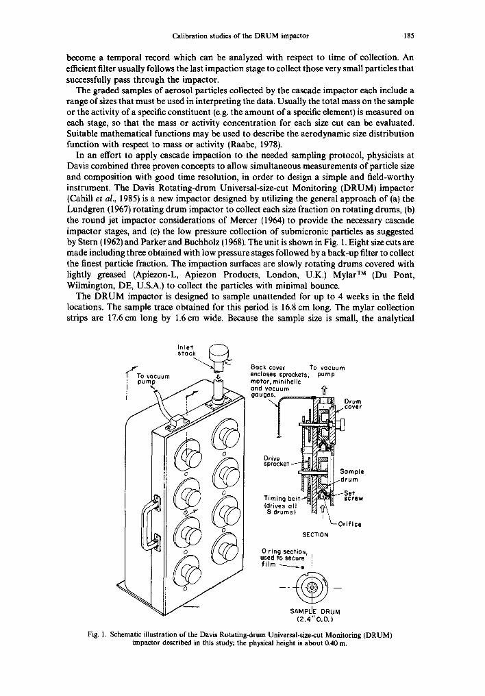
In an effort to apply cascade impaction to the needed sampling protocol, physicists at Davis combined three proven concepts to allow simultaneous measurements of particle size and composition with good time resolution, in order to design a simple and field-worthy instrument. The Davis Rotating-drum Universal-size-cut Monitoring (DRUM) impactor (Cahill et al., 1985) is a new impactor designed by utilizing the general approach of (a) the Lundgren (1967) rotating drum impactor to collect each size fraction on rotating drums, (b) the round jet impactor considerations of Mercer (1964) to provide the necessary cascade impactor stages, and (c) the low pressure collection of submicronic particles as suggested by Stern (1962) and Parker and Buchholz (1968). The unit is shown in Fig. 1. Eight size cuts are made including three obtained with low pressure stages followed by a back-up filter to collect the finest particle fraction. The impaction surfaces are slowly rotating drums covered with lightly greased (Apiezon-L, Apiezon Products, London, U.K.) Mylar TM (Du Pont, Wilmington, DE, U.S.A.) to collect the particles with minimal bounce.
The DRUM impactor is designed to sample unattended for up to 4 weeks in the field locations. The sample trace obtained for this period is 16.8 cm long. The mylar collection strips are 17.6 cm long by 1.6 cm wide. Because the sample size is small, the analytical
In le t
ffTo vocuu,,, s t o c ~ , ~ Back cover To vacuum encloses sprockets, pump motor, minihelic and vacuum gouges.
, Drum ~.,cover
Drive
Somple ,,-drum
sproc I
l - S e t Timing belt- screw (drives ol l B drums)
Orifice SECTION
0 r ing section, used to secure I f i lm ---____.. e
SAM pLIE: DRUM ( 2 . 4 " O.D.)
Fig. 1. Schematic illustration of the Davis Rotating-drum Universal-size-cut Monitoring (DRUM) impactor described in this study; the physical height is about 0.40 m.

186 OTTO G. RAABE et al.
methods determine the resolution of the deposit. Utilizing nuclear Particle Induced X-ray Emission (PIXE; Cahill, 1980), elemental analysis can be obtained having a time resolution of 4 h for a sample period of 14 days, while still obtaining minimum detectable limits for most chemical elements at the few ng m- 3 level. The entire 22 kg unit can fit under the seat of a commercial jet airplane for easy transport.
The size cuts of the original DRUM involved approximately logarithmic size-cut effective cut-off aerodynamic equivalent diameters (ECDae), each differing by about a factor of two from its neighbors. Two low pressure stages were added to the design of a Mercer-style impactor (Mercer et al., 1970). Excellent unit-to-unit precision was achieved for four units tested side-by-side (Fig. 2), with good absolute agreement with simple concurrent filter samples. The DRUM sampler participated informally in the Desert Research Institute Intercomparison Study, yielding very good agreement with much simpler units during 7 days of sampling. Formal third-party quality assurance audits have been performed as part of one of the field programs using the DRUM, including analytical sensitivity, time resolution, precision, and accuracy.
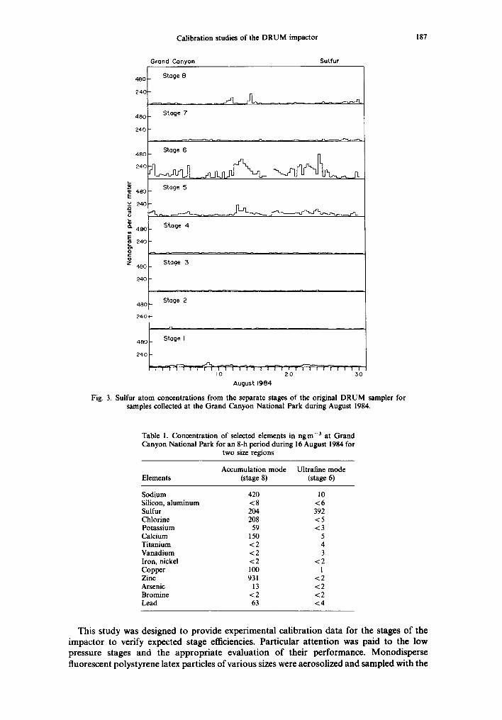
The DRUM samplers have been used in field studies of environmental aerosols in the western United States, specifically for evaluation of visibility degradation. In addition to the Arctic aerosols aircraft program, AGASP-II, the RESOLVE and SCENES deposition programs, and National Park Service Particulate Monitoring Network (at Grand Canyon and Sequoia National Parks) have all used DRUM samplers. An example of the kinds of results that have been achieved is shown in Fig. 3. During the month of August, 1984, sulfur- containing aerosol particles at the Grand Canyon National Park varied independently in time and composition in a very coarse mode (> 8.0/~m), an accumulation mode (around 0.3 #m), and an ultrafine mode ( < 0.1 #m). The diameter differences in composition between an ultrafine mode maximum and accumulation mode maximum on 17 August are shown in Table 1. The ultrafine mode which can comprise 30 % of the total sulfur concentration under arid, summertime conditions at this site, had clear contributions from primary copper- smelter-emitted particles (based upon the presence of the elements Cu, Zn, As, and Pb) that are absent from the accumulation mode. Hence, the sulfur in the accumulation mode can be attributed to sulfur dioxide conversion to sulfate. These types of data have needed to be further supported with improved size calibrations, studies of collection efficiencies and losses, and other operational evaluations of the DRUM to take greater advantage of this useful sampling methodology.
0.5
0.4
o.~
0.2
0.1
ROOF TEST T Four DRUM Impoctors |
o Silicon 10/83 U.C. Dovis • Potossium ZX Sul fur O Chlorine (T-9) t ' //
i ",/ . . / / \
Diometer (/~ml (1/16) (1/8) I /4 I /2 I 2 4 8
Fig. 2. Comparison test of four DRUM samplers; the uncertainties represent the standard deviations of the four units for the relative amount seen on each stage for each element.
Calibration studies o f the D R U M impactor 187
480 Stage 7
240
480
240
e 480 E u 240
o. 480
240
c
4 8 0
2 4 0
480
240
480
240
Grand Canyon Sulfur
Stage 8 480
240
Stage 6
Stage 5
Stage 4
Stage 3
Stage 2
,.n
Stage I
, , ~ - i " - q - ~ , , , ,7q1- , , ~ ' i - q - , r q - i , ' 7 - ; ~ - , 3 , , , , , , , , , I 0 20 30
August 1984
Fig. 3. Sulfur a tom concentrations from the separate stages of the original D R U M sampler for samples collected at the Grand Canyon National Park during August 1984.
Table 1. Concentration of selected elements in n g m -3 at Grand Canyon National Park for an 8-h period during 16 August 1984 for
two size regions
Accumulation mode Uitrafme mode Elements (stage 8) (stage 6)
Sodium 420 10 Silicon, a luminum < 8 < 6 Sulfur 204 392 Chlorine 208 < 5 Potassium 59 < 3 Calcium 150 5 Titanium < 2 4 Vanadium < 2 3 Iron, nickel < 2 < 2 Copper 100 1 Zinc 931 < 2 Arsenic 13 < 2 Bromine < 2 < 2 Lead 63 < 4
This study was designed to provide experimental calibration data for the stages of the impactor to verify expected stage efficiencies. Particular attention was paid to the low pressure stages and the appropriate evaluation of their performance. Monodisperse fluorescent polystyrene latex particles of various sizes were aerosolized and sampled with the
188 OTTO G. RAABE et al.
DRUM impactor to observe the collection efficiencies of the stages with particles of known aerodynamic size. The results, which were non-dimensionalized for general usefulness, showed the importance of utilizing the local gas conditions in describing the impaction process. The original DRUM calibration was established, and an improved design was recommended. Computer and pocket calculator programs were developed to quickly calculate the effective cut-off aerodynamic diameter of a single stage of a round jet impactor whether at ambient or reduced pressure and whether at sonic, near sonic, or subsonic jet speed.
METHODS
Impactor operation
The collection efficiency of a single stage of an impactor depends upon several geometric and dynamic factors including: (a) particle size (the diameter, D, for a spherical particle); (b) the particle physical density, p; (c) the particle shape; (d) the Cunningham slip correction, C(D) (important for submicrometer particles); (e) the linear velocity of the air stream at the orifice outlet (usually described by a hypothetical average, Uo, equal to the volumetric flow rate, Qo, divided by the cross-sectional area of the orifice outlet); (f) the dynamic characteristics of the jet air flow (conveniently described by the air flow Reynolds' number, Re, at the orifice outlet); (g) the dynamic viscosity of the air, r/; (h) the flow orifice shape and size (conveniently described by the outlet diameter, W, for cylindrical orifices); (i) the distance, S, from the orifice outlet to the collection surface; and (j) the orifice throat length, T.
It is assumed that a single aerosol particle exits an orifice at a velocity, Vp, equal to the gas velocity, vg, and that they are equal to the maximum average velocity of the airstream jet, u o. As the airstream turns to avoid the collector, the particle decelerates in the direction of the collector under a drag force (F = ma) given by Stokes' law:
/)g -- Fp = m dvp B d t ' (1)
where B is the particle mobility, m is the particle mass, and t is time. Based upon the principles of physical and dynamic similarity and dimensional analysis, the behavior of the particle and its associated collection probability or efficiency can be expressed in non-dimensionalized general form by normalizing the various factors in the equation of motion in the direction perpendicular to the collector so that equation (1) is multiplied by W/2u2o and the dimensionless t* = 2Uot/Wand velocities v~ = Vg/Uoand Vp-* - Vp/Uoare substituted to yield:
dr; (2) * - *= (Stk) /)g Vp dt*'
where the mass of the particle has been replaced by the dimensionless Stokes' number as defined by:
, 2 Stk - 2taBu° - u°p Dar (3)
W 9q W '
where ~ is the dynamic viscosity and u o is the calculated average velocity of the air stream at the jet exit, p* is a standard reference physical density equal to 1 g cm-3 used to define the aerodynamic diameter, W is the jet diameter (for cylindrical jets) and Dar is the aerodynamic resistance diameter of the particle given by Raabe (1976) as:
D x/[pC(D)] _ Dex/[pC(Ds) ] Dar -- x / P * x/(t<p,) , (4)
where p is the physical density of a spherical particle of physical diameter D and C(D) is the Cunningham slip correction used to correct Stokes' law of particle drag for violation of the no-slip boundary condition between the particle and air molecules. The right hand
Calibration studies of the DRUM impactor 189
relationship is for non-spherical particles where D e refers to the equivalent volume diameter, K the dynamic shape factor, and D s to the equivalent slip diameter of a non-spherical particle (Raabe, 1976).
The slip correction can be calculated for spherical solid aerosol particles in air using (Allen and Raabe, 1985):
C(Kn) = 1 + AKn, (5)
with Kn the Knudsen number equal to 2)~/D, where 2 is the gas molecule mean free path, and
A = ct + fl exp ( - ¢/gn) (6)
where a, fl, and ¢ are characteristic parameters whose values for solid particles are 1.142, 0.558, and 0.999, respectively (Allen and Raabe, 1985).
The aerodynamic equivalent diameter, Dae, defined as the unit density (1 g cm-3) sphere having the same settling velocity as a specified aerosol particle, is related to Dar by:
Oae = Dar/x/[C(Oae)] , (7)
where C(Dae ) is the slip correction appropriate for a spherical particle of physical diameter D ae •
An efficiency function given as a function of Stokes' number will apply for all sizes of particles and impactor orifices as long as physical and dynamic similarity is maintained, i.e. T/W, S/W, and Re are fixed (Marple, 1970; Newton et al., 1977). Marple developed a theoretical description of the shape of the efficiency function and its variation with S/W and Re. Mercer (1965) demonstrated the usefulness of describing the efficiency function in terms of the effective cut-off aerodynamic diameter (ECDae or ECDar), defined as the particle size (with corresponding Stokes' number) having a 50 ~o collection efficiency. When the Stk for 50 ~o collection efficiency is known, the ECDar can be calculated from:
ECDar = x/(9n W Stk/uoP*), (8)
and ECDae can be calculated from ECDar for the local pressure and temperature conditions. In order to utilize this non-dimensional analysis for sonic and near sonic jets, a discharge coefficient, c, was used to correct the cross-sectional area of the orifice for the effect of flow stream contraction in choked or partially choked flow for calculating the jet velocity, uo; therefore, the square root of c was multiplied by W to yield the effective jet diameter for equation (8).
The mean free path of air molecules in the outlet jet flow is given by:
S* p . .1-t T . ~
2o = ).* ( ~ ) ( ~ o ) ( 1 - ~ . ) , (9,
To where Po is the static pressure and T O is the absolute temperature of the air, S* is the Sutherland correction equal to l10.4K, P * = 101.3kPa and T* = 296.15K at which conditions 2* = 0.0673/~m (Allen and Raabe, 1985).
Likewise, the dynamic viscosity of the air can be calculated from (Allen and Raabe, 1982):
r / o : r / . ( To "~1'5(296.15+__S*) \296.15./ \ To+S* '
(10)
where r/* is the viscosity of air at 23°C (296.15 K) equal to 1.832 x 10⁻⁵ kgm- 1 s- Traditional analyses of impactor performance have been based upon incompressible fluid
flow, which approximately holds for air exiting an impactor stage when u o < s/3, where s is the speed of sound in that air. However, in impactors such as the DRUM where high velocities and gas expansion are used at the latter stages to collect submicrometer particles, the temperature and pressure of the air jet at the orifice outlet will vary with local Mach
190 OTTO G. RAABE el al.
number, M = Uo/S. For adiabatic expansion in isentropic flow, the temperature and pressure can be calculated from:
Ti /T o = 1 + (), - 1)M2/2 (11)
Pi/Po = [1 + 0' - 1)M2/2] ~'/c~ ~ (12)
where 7 is the ratio of specific heat capacity of a gas at constant pressure to that at constant volume (7 = 1.4 for air), Toand Poare the absolute temperature and pressure of the gas at the orifice outlet, and Tiand Pi refer to the gas properties at the orifice inlet prior to the expansion (Imrie, 1973).
Also, the velocity of the air jet exiting an orifice outlet is affected by the contraction of the air flow cross-section by a factor c (the discharge coefficient) as the air passes through the cylindrical channel. For compressible flow through an impactor orifice with 1 < T~ W < 5, the discharge coefficient was estimated by c = To/T i. Critical flow in an impactor orifice occurs when the exit velocity reaches the speed of sound, s, at the local conditions (i.e. M = 1), given by:
s = x / ( ) 'aTo/Ma) , (13)
where R is the molar universal gas constant (8.314 J K 1), To is the absolute temperature, and M a is the average molecular weight of the gas (28.96 kg kmol ~ for standard air). At critical flow, Po = 0.528Pi and T O = 0.833T i. Further reduction in pressure drop does not increase the flow at this limit, but does cause the air to continue to expand after exiting the stage orifice. Between the jets the airstream kinetic energy is largely dissipated so that the interstage temperatures can return to the ambient temperature of the air being sampled.
The ECDae values calculated from equation (8) using equation (7) are based upon local conditions in the air stream at the orifice outlet and p = p*. When M < 0.3 these values are essentially equivalent to the aerodynamic equivalent diameters of the sampled aerosols. However, when M > 0.3, the calculated effective cut-off aerodynamic diameters will not correspond exactly to the ambient aerodynamic diameters of sampled aerosols when p # p*. In practice this discrepancy is not large, however. The calculated ECDae values for sonic jets are usually well within 10~o of the ambient value when 0.5 < p < 10.
Experimental methods
The performance of the DRUM impactor was evaluated using aerosols generated from aqueous suspensions of monodisperse Polybead TM polystyrene (p -- 1.047 g cm- 3) fluor- escent microsphere (Polysciences, Warrington, PA). Six different monodisperse sizes were used having physical diameters ranging from 0.0669 to 5.52/~m. Sphere size was determined with transmission electron microscopy by comparison to a standard diffraction grating replica (Ladd Research Industries, Burlington, VT). Prior to aerosolization, the particle suspensions were washed with deionized water to remove surfactant (Allen and Raabe, 1985). The suspensions were diluted to concentrations that produced negligible ( < 1 ~o) multiplets when nebulized (Raabe, 1968); this was confirmed during each test utilizing a Climet 225 light scattering particle counter (Climet Instruments, Redlands, CA). The suspensions were aerosolized with a Lovelace nebulizer (Mercer et al., 1968). The aerosol was passed through a heated (40°C) and desiccated diffusion drying chamber and then through a radioactive krypton-85 (85Kr) discharger to reduce electrostatic charge to Boitzmann equilibrium (Teague et al., 1978). Samples of these aerosols were collected at several different selected flow rates up to the critical flow using the DRUM impactor.
The samples were collected in the DRUM impactor on Mylar strips coated with Antifoam- A (DOW Chemical, Midland, MI) to prevent particle bounce or entrainment after collection. A membrane filter after the DRUM impactor collected the particles that passed through the eight stages of the unit. Sampling times ranged from several minutes to several hours depending upon the mass concentration of the aerosol being sampled. Pressures were measured in each test at stages 3, 6 and 8, as well as after the final filter; the pressures of the
Calibration studies of the D R U M impactor 191
remaining stages were calculated by comparison to previous calibrations of the stage pressures vs flow rate.
After sampling, the Mylar substrates and back-up filter containing the deposited particles were removed from the DRUM and each was mixed in a separate glass vial with 5 ml of analytical reagent grade toluene to dissolve the polystyrene particles and release their fluorescent label into solution. The toluene solution was assayed for fluorescence with a Turner fluorometer (Turner Instrument, Mountain View, CA). Suitable blanks were measured for standardization. The fluorescent reading was proportional to the amount of collected aerosol. The quantities of each aerosol collected on each stage and the back-up filter were used to evaluate the fractional collection efficiency of the principal collector stage in each case. Typically the monodisperse particles were only collected on one or two stages of the DRUM impactor.
A separate study was conducted to determine typical wall losses in the DRUM impactor during sampling of polydisperse respirable environmental aerosols. Polydisperse aerosols (MMAD = 0.88 #m, trg = 1.8) were generated with a Lovelace nebulizer (Mercer et al., 1968), dried with a diffusion drier, and reduced to Boltzmann equilibrium with a radioactive 85Kr discharger. The aerosol was sampled at a flow rate of 18.3 cm 3 s - 1, and was collected directly onto Antifoam-A-coated collection drums. Sampling times varied from 45 to 75 min. After sampling, the drums, final filter, separated orifice units, and all interior walls of the DRUM sampler were washed with slightly alkaline water, and assayed with the Turner fluorometer to determine relative distribution of collected aerosol particles by mass. That portion of the collected aerosol not found upon the drums or on the final filter represented the operational losses.
R E S U L T S
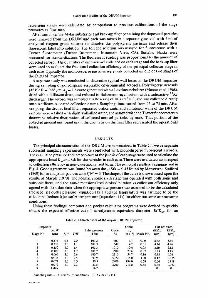
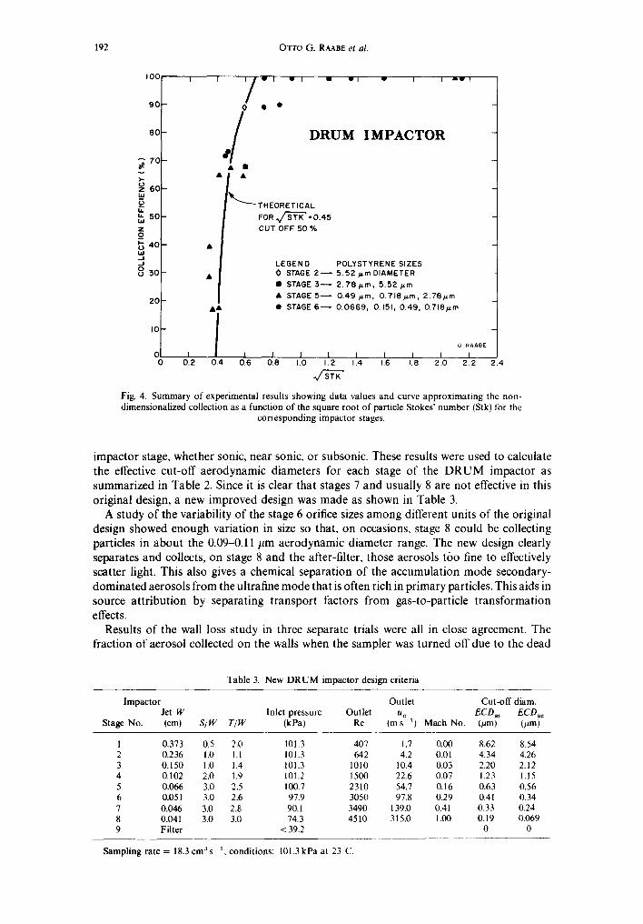
The principal characteristics of the DRUM are summarized in Table 2. Twelve separate successful sampling experiments were conducted with monodisperse fluorescent aerosols. The calculated pressure and temperature at the jet exit of each stage were used to calculate the appropriate local Dar and Stk for the particles in each case. These were evaluated with respect to collection efficiency in non-dimensionalized form. The principal results are summarized in Fig. 4. Good agreement was found between the x/Stk = 0.45 found by Mercer and Stafford (1969) for round jet impactors with S/W = 3. The shape of the curve is drawn based upon the results of Marple (1970). The normally sonic sixth stage was operated with both sonic and subsonic flows, and the non-dimensionalized Stokes' number vs collection efficiency only agreed with the other data when the appropriate pressure was assumed to be the calculated (reduced) jet outlet pressure [equation (12)] and the temperature was assumed to be the calculated (reduced) jet outlet temperature [equation ( 11)] for either the sonic or near sonic conditions.
Using these findings, computer and pocket calculator programs were devised to quickly obtain the expected effective cut-off aerodynamic equivalent diameter, ECDae, for an
Table 2. Characteristics o f the original D R U M impactor
Impactor Outlet Cut-off diam. Jet W Inlet pressure Outlet u o ECDar ECDac
Stage No. (cm) S/W T/W (kPa) Re (ms -1) Mach No. (/am) (#m)
1 0.373 0.5 2.0 101.3 407 1.7 0.00 8.62 8.54 2 0.236 3.0 1.1 101.3 642 4.2 0.01 4.34 4,26 3 0.150 3.0 1.4 101.3 1010 10.4 0.03 2.20 2.12 4 0.102 3.0 1.9 101.2 1500 22.6 0.07 1.23 1.15 5 0.066 3.0 2.6 100.7 2310 54.7 0.16 0.63 0.56 6 0.035 3.0 2.5 97.9 5070 315.0 1.00 0.17 0.075 7 0.071 3.0 2,5 30.3 2400 194.0 0.58 0.34 0.119 8 0.079 3.0 2.3 23.5 2200 211.0 0.64 0.34 0.093 9 Filter 16.7 0 0
Sampling rate = 18,3 cm 3 s - l ; conditions: 101.3 kPa at 23 ° C.
AS 19:2-C
192 OTTO G. RAABE et al,
v
1,1
,.'t hj Z O_
=, .J 8
I 00
9 0
80
70
6 0
5 0
4 0
30
2 0
I0
0 I 0 0 .2
, /-, 0 • • ,/
W I U ~ 1
D R U M
THEORETICAL FOR .~ STK" = 0.45 CUT OFF 50 %
w I I
I M P A C T O R
m w l
LEGEND POLYSTYRENE SIZES 0 STAGE 2 ~ 5 .52 p.rn DIAMETER • STAGE 3 ~ 2 .78p .m, 5 .52 p.m • STAGE 5 ~ 0 . 4 9 p m , O.718p.m, 2.78#.rn • STAGE 6 ~ 0 .0669 , 0.151, 0.49, 0.718pro A&
o RAABE I- I I I I I J I I
0.4 0.6 0.8 1.0 1.2 1.4 1.6 1.8 2.0 2.2
~JSTK" 2.4
Fig. 4. Summary of experimental results showing data values and curve approximating the non- dimensionalized collection as a function of the square root of particle Stokes' number (Stk) for the
corresponding impactor stages.
impactor stage, whether sonic, near sonic, or subsonic. These results were used to calculate the effective cut-off aerodynamic diameters for each stage of the DRUM impactor as summarized in Table 2. Since it is clear that stages 7 and usually 8 are not effective in this original design, a new improved design was made as shown in Table 3.
A study of the variability of the stage 6 orifice sizes among different units of the original design showed enough variation in size so that, on occasions, stage 8 could be collecting particles in about the 0.09-0.11 #m aerodynamic diameter range. The new design clearly separates and collects, on stage 8 and the alter-filter, those aerosols too fine to effectively scatter light. This also gives a chemical separation of the accumulation mode secondary- dominated aerosols from the ultrafine mode that is often rich in primary particles. This aids in source attribution by separating transport factors from gas-to-particle transformation effects.
Results of the wall loss study in three separate trials were all in close agreement. The fraction of aerosol collected on the walls when the sampler was turned off due to the dead
Table 3. New D R U M impactor design criteria
lmpactor Outlet Cut-off diam. Jet W Inlet pressure Outlet u o ECDar ECDae
Stage No. (cm) S/W T/W (kPa) Re (m s ~ ) Mach No. (/~m) (#m)
1 0.373 0.5 2.0 101.3 407 1.7 0.00 8.62 8.54 2 0.236 1.0 1.1 101.3 642 4.2 0.01 4.34 4.26 3 0.150 1.0 1.4 101.3 1010 10.4 0.03 2.20 2.12 4 0.102 2.0 1.9 101.2 1500 22.6 0.07 1.23 1.15 5 0.066 3.0 2.5 100.7 2310 54.7 0.16 0.63 0.56 6 0.051 3.0 2.6 97.9 3050 97.8 0.29 0.41 0.34 7 0.046 3.0 2.8 90.1 3490 139.0 0.41 0.33 0.24 8 0.041 3.0 3.0 74.3 4510 315.0 1.00 0.19 0.069 9 Filter < 39.2 0 0
Sampling rate = 18.3 cm 3 s 1; conditions: 101.3 kPa at 23~'C.

Calibration studies of the D R U M impactor 193
space volume of the sampler was calculated from the observed average aerosol concentration and subtracted from the measured wall deposit to obtain the operational losses. The observed wall losses were 5.8, 7.4 and 8.8 ~; the associated jet losses were 2.6, 3.7 and 3.8 ~, respectively. The overall average operational losses during sampling of the polydisperse test aerosol were 10.7 ~o (1.2 ~ S.E.).
D I S C U S S I O N
The size distributions of environmental aerosols and their component constituents are an important indication of source characteristics and of other significant properties. In addition, the temporal patterns of these size distributions are a necessary part of the information needed to interpret aerosol kinetics. An aerosol sampler such as the DRUM impactor that can provide size distribution and concentration data as a function of time is a valuable tool in improving our understanding of environmental aerosols and air pollution. The results of the calibration and efficiency studies provide an improved understanding of the particle separation and collection characteristics of the DRUM sampler. Use of the improved design (Table 3) will help clarify the properties of airborne particles in the accumulation and ultrafine size modes.
An impactor jet that achieves gas velocities larger than about one-third the speed of sound at the local condition also involves a reduced temperature in the high speed air jet as kinetic energy is transferred to the air stream. This low temperature is usually below the dew point for water or other constituents. Condensation has not been found to be a problem, however, apparently because the reduced temperature is reached instantaneously and maintained for only a short time (about 4/~s for the sonic stage of the new DRUM); during this short time only water molecules a few micrometers from the aerosol particle surfaces have time to diffuse to them.
This experimental study of the DRUM impactor provides a method for evaluation of the expected performance of low-pressure impactor stages using the non-dimensionalized efficiency curve for the impactor stages. The low-pressure and sonic stages were found to conform reasonably well with the other stages when the Stokes' number was calculated as described using the local conditions at the orifice outlet for each impactor stage, rather than at assumed stagnation conditions at the collection stage. The purpose of this approach is to provide a unifying model for prediction purposes, even though the exact physical implications may be more complex. This was tested using these methods to reconstruct the expected operating conditions of an existing low-pressure impactor. The operating characteristics of the Hering et al. (1978) low-pressure impactor were calculated with this approach. The results are given in Table 4. The comparison of the calculated ECDae values vs
Table 4. Calculated vs reported values for Hering impactor a
Impactor Inlet Jet W pressure Outlet
Stage No. (cm) S/W T]W (kPa) Re
Outlet Cut-off diam. u o Reported Calculated
(ms - t ) Mach No. ECDae~m ) ECDae~m )
1 0.249 0.5 2.4 99.3 554 3.5 0.01 4.0 4.800 2 O. 140 0.5 4.3 99.2 985 11.0 0.03 2.0 1.98 3 0.099 0.5 6.1 99.1 1390 22.1 0.06 1.0 1.14 4 0.064 0.5 9.4 98.7 2170 54.0 0.16 0.5 0.55 5 b 0.110 0.5 5.5 20.0 1290 93.5 0.27 0.26 0.28 6 0.099 0.5 6.1 18.7 1470 130.0 0.38 0.11 0.17 7 0.099 0.5 6.1 14.1 1580 197.0 ¢ 0.59 0.075 0.079 8 0.140 0.5 4.3 6.7 1150 220.0 c 0.67 0.05 0.045 9 Filter 1.1 0 0
aHering et al. (1978). bA non-collecting, 0.036 cm diameter, sonic pressure reduction orifice preceded stage 5 yielding an upstream
pressure of 20 kPa. CHering et al. (1978) reported sonic 300.0 m s - t for stages 7 and 8. dThe actual cut-off may be smaller for stage No. 1 because of gravitational collection of larger particles. Sampling rate = 17 cm a s - t; conditions: 99.3 kPa at 23°C.
194 OTTO G. RAABE et al.
the experimental values appears reasonable lor most of the stages even though the S/W = 0.5 is smaller than the S/W -- 3.0 of Fig. 4. The use of the value x/Stk = 0.45 for round jets with S/Wfrom 0.5 to 3 with Re from a few hundred to a few thousand is supported by these results.
Acknowledgements~he research was supported by the National Park Service under Contract No. USDICX-0001- 3-0056. A portion of this work was performed in facilities at the Laboratory for Energy-related Health Research supported by the Office of Health and Environmental Research of the U.S. Department of Energy under Contract No. DE-AC03-76SF00472 with the University of California, Davis.
R E F E R E N C E S
Allen, M. D. and Raabe, O. G. (1982) Revaluation of Millikan's oil drop data for the motion of small particles in air. J. Aerosol Sci. 13, 537-547.
Allen, M. D. and Raabe, O. G. (1985) Slip correction measurements of spherical solid aerosol particles in an improved Millikan apparatus. Aerosol Sci. Technol. 4, 269-286.
Cahill, T. A. (1980) Proton microprobes and particle-induced X-ray analytical systems. A. Rev. Nucl. Part. Sci. 30, 211-252.
Cahill, T. A., Goodart, C., Nelson, J. W., Eldred, R. A., Nasstrum, J. S. and Feeney, P. J. (1987) Design and evaluation of the DRUM impactor. In Particulate and Multiphase Processes, Vol. 2, Contamination Analysis and Control (Edited by Ariman, T. and Veziroglu, T. N.), pp. 319-325. Hemisphere Publishing Corporation, Washington DC, U.S.A.
Hering, S. V., Flagan, R. C. and Friedlander, S. K. (1978) Design and evaluation of new low-pressure impactor. Envir. Sci. Technol. 12, 667-673.
lmrie, B. W. (1973) Compressible Fluid Flow. John Wiley, New York. Lundgren, D. A. (1967) An aerosol sampler for determination of particulate concentration as a function of size and
time. d. Air Pollut. Control Ass. 17, 225-229. Marple, V. (1970)A fundamental study of inertial impactors, Ph.D. thesis, University of Minnesota. May, K. R. (1945) The cascade impactor: an instrument for sampling coarse aerosols. J. scient, lnstrum. 22, 187-195. Mercer, T. T. (1964) The stage constants of cascade impactors. Ann. occup. Hyg. 7, 115-124. Mercer, T. T. (1965) The interpretation of cascade impactor data. Am. ind. Hyg. Ass. J. 26, 236-241. Mercer, T. T. and Stafford, R. G. (1969) Impaction from round jets. Ann. occup. Hyg. 12, 41-48. Mercer, T. T., Tillery, M. I. and Chow, H. Y. (1968) Operating characteristics of some compressed air nebulizers. Am.
ind. Hyg. Ass. J. 29, 66-78. Mercer, T. T., Tillery, M. I. and Newton, G. J. (1970) A multi-stage low flow rate cascade impactor. J. Aerosol Sci. !,
9-15. Newton, G. J., Raabe, O. G. and Mokler, B. O. (1977) Cascade impactor design and performance. J. Aerosol Sci. 8,
339-347. Raabe, O. G. (1968) The dilution of monodisperse suspensions for aerosolization. Am. ind. Hyg. Ass. J. 29, 439-443. Raabe, O. G. (1976) Aerosol aerodynamic size conventions for inertial sampler calibration, J. Air Pollut. Control Ass.
26, 856-860. Raabe, O. G. (1978) A general method for fitting size distributions to multicomponent aerosol data using weighted
least-squares. Envir. Sci. Technol. 12, 1162-1167. Parker, G. W. and Buchholz, H. (1968) Size classification of submicron particles by a low pressure cascade impactor,
ORNL-4226. Oak Ridge National Laboratory, Oak Ridge, Tennessee. Stern, S. C. (1962) Collection efficiency of jet impactors at reduced pressure. Ind. Engng Chem. Fundamentals I,
273-277. Teague, S. V., Yeh, H. C. and Newton, G. J. (1978) Fabrication and use of krypton-85 aerosols discharge devices. Hlth
Phys. 35, 392 395.
A P P E N D I X
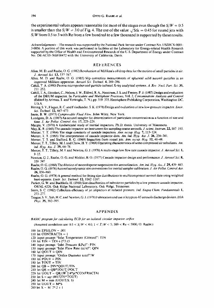
BASIC program for calculating ECD Jbr an isolated circular impactor orifice
(Assumed conditions are: 0.5 < S / W < 4.0; 1 < T / W < 5; 500 < Re < 5000; O. Raabe.)
100 let EPSILON = .001 110 let CONTRACTA = 1 120 input prompt "Inlet Temperature (Celsius)?": TIN 130 let TIN = TIN +273.15 140 input prompt "Inlet Pressure (kPa)?": PIN 150 input prompt "Inlet Flow Rate (cc/s)?": QIN 160 let QOUT = QIN 170 input prompt "Orifice Diameter (cm)?":W 180 let POUT = PIN 190 let TOUT = TIN 200 let QB = P1N*QOUT/TIN 210 let QR = QB*TOUT,/POUT 220 let UOUT = QR/(W 2/4*pi*CONTRACTA) 230 let S = sqr (4017270*TOUT) 240 let M = min IUOUT/S, 1) 250 let UOUT = M*S 260 let X = M-2".2 + I
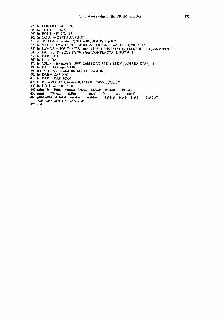
Calibration studies of the DRUM impactor 195
270 let CONTRACTA = 1/X 280 let TOUT = TIN/X 290 let POUT = PIN/X ~ 3.5 300 let QOUT = QB*TOUT/POUT 310 if EPSILON < = abs ((QOUT-QR)/QOUT) then 00210 320 let VISCOSITY = 1.832E - 04*406.55/(TOUT + 110.4)* (TOUT/296.15)~l.5 330 let LAMDA = TOUT* 6.73E - 06* 101.3" (110.4/296.15 + l)/(110.4/TOUT + 1)/296.15/POUT 340 let DA = sqr (V1SCOSITY*W*9*sqr(CONTRACTA)/UOUT)*.45 350 let DAR = DA 360 let DR = DA 370 let CSLIP = (exp(DA*( - .999)/LAM BDA/2)*.558 + 1.142)* (LAMBDA/DA*2) + 1 380 let DA = DAR/sqr(CSLIP) 390 if EPSILON < = abs(DR-DA)/DA then 00360 400 let DAE = DA*I0000 410 let DAR = DAR*I0000 420 let RE = POUT*.003484/TOUT*UOUT*W/VISCOSITY 430 let UOUT = UOUT/100 440 print"Jet P(in) Re(out) U(out) MACH ECDar ECDae" 450 print "W(cm) (kPa) (m/s) No. (urn) (urn)" 460 print u s i n g " # . # # # # # # . # # # # # # # # . # # . # # # . # # # . # # # " :
W,PIN,RE,UOUT,M,DAR,DAE 470 end