
Calculating the Volume of Water Droplets on ...
9
Purdue University Purdue e-Pubs International Refrigeration and Air Conditioning Conference School of Mechanical Engineering 2008 Calculating the Volume of Water Droplets on Topographically-Modified, Micro-Grooved Aluminum Surfaces Andrew Sommers Miami University Anthony M. Jacobi University of Illinois at Urbana-Champaign Follow this and additional works at: hp://docs.lib.purdue.edu/iracc is document has been made available through Purdue e-Pubs, a service of the Purdue University Libraries. Please contact [email protected] for additional information. Complete proceedings may be acquired in print and on CD-ROM directly from the Ray W. Herrick Laboratories at hps://engineering.purdue.edu/ Herrick/Events/orderlit.html Sommers, Andrew and Jacobi, Anthony M., "Calculating the Volume of Water Droplets on Topographically-Modified, Micro-Grooved Aluminum Surfaces" (2008). International Reigeration and Air Conditioning Conference. Paper 931. hp://docs.lib.purdue.edu/iracc/931
Transcript of Calculating the Volume of Water Droplets on ...

Purdue UniversityPurdue e-PubsInternational Refrigeration and Air ConditioningConference School of Mechanical Engineering
2008
Calculating the Volume of Water Droplets onTopographically-Modified, Micro-GroovedAluminum SurfacesAndrew SommersMiami University
Anthony M. JacobiUniversity of Illinois at Urbana-Champaign
Follow this and additional works at: http://docs.lib.purdue.edu/iracc
This document has been made available through Purdue e-Pubs, a service of the Purdue University Libraries. Please contact [email protected] foradditional information.Complete proceedings may be acquired in print and on CD-ROM directly from the Ray W. Herrick Laboratories at https://engineering.purdue.edu/Herrick/Events/orderlit.html
Sommers, Andrew and Jacobi, Anthony M., "Calculating the Volume of Water Droplets on Topographically-Modified, Micro-GroovedAluminum Surfaces" (2008). International Refrigeration and Air Conditioning Conference. Paper 931.http://docs.lib.purdue.edu/iracc/931

2282, Page 1
International Refrigeration and Air Conditioning Conference at Purdue, July 14-17, 2008
CCalculating the Volume of Water Droplets on Topographically-Modified, Micro-Grooved Aluminum Surfaces
Andrew D. SOMMERS 1,*,†Anthony M. JACOBI 2
1 Dept. of Mechanical and Manufacturing Engr. 2 Dept. of Mechanical Science and Engineering Miami University, 56 Engineering Bldg. University of Illinois, 1206 West Green St.
Oxford, OH 45056 USA Urbana, IL 61801 USAPhone: (513) 529-0718 Phone: (217) 333-4108
Fax: (513) 529-0717 Fax: (217) 244-6534
ABSTRACT Water droplets on micro-patterned surfaces consisting of parallel grooves tens of microns in width and depth is considered, and a method for calculating the droplet volume on these surfaces is presented. This model which utilizes the elongated and parallel-sided nature of water droplets condensed on micro-grooved surfaces requires inputs from two water droplet images at = 0 and = 90 — namely, the droplet major axis, minor axis, height, and two contact angles. In this method, a circular cross-sectional area is extruded the length of the droplet where the chord of the extruded circle is fixed by the width of the droplet. The maximum apparent contact angle is assumed to occur along the side of the droplet because of the surface energy barrier to wetting caused by the grooves—abehavior that was observed experimentally. When applied to water droplets condensed onto a micro-grooved aluminum surface, this method was shown to calculate the actual droplet volume to within 10% for 88% of the droplets analyzed. This method is useful for estimating the volume of retained water droplets on micro-textured surfaces where the surface micro-channels are aligned parallel to gravity and both heat and mass transfer occur.
1. INTRODUCTIONIn a broad range of air-cooling applications, water retention on the heat transfer surface is problematic, because it can reduce the air-side heat transfer coefficient, increase the core pressure drop, and provide a site for biological activity. In refrigeration systems, the accumulation of frost on the heat exchanger requires periodic defrosting and attendant energy expenditures. When water is retained on these surfaces following the defrost cycle, ice is more readily formed in the subsequent cooling period, and such ice can lead to shorter operational times between defrost cycles. Thus the drainage of water, whether from condensation or melting frost, is very important to the overall performance of heat transfer systems.
The objective of this work was to devise a method for predicting the volume of a water droplet that has condensed onto a micro-grooved heat transfer surface using only a few simple parameters that can be gleaned from two droplet images—a frontal image and a side image. A method for accurately calculating the droplet volume is a necessary aspect to water retention modeling and droplet distribution functions. Thus the engineering value of this researchrests in its direct application to the modeling and control of condensate on heat transfer surfaces used in dehumidification and air-cooling systems. This work also provided a better understanding of the anistropic wettability of a highly controlled surface microstructure which might facilitate new surface designs with improved liquid drainage behavior. As part of an effort to provide guidance for the design of these surfaces, the applicability of current models, tacitly based on an assumption of isotropic wetting, and their ability to provide reliable prediction of water droplet volume on these new surfaces was also evaluated. Because droplet shapes on surfaces with anisotropic wetting behavior are different from those on conventional, isotropic surfaces, existing models were observed to be either inadequate or less accurate.
In an early theoretical study of the effect of surface heterogeneity on the contact angle of stripwise patterned surfaces, Neumann and Good (1972) found that for line widths below about 0.1 m, the amplitude of the periodic contortion of the three-phase contact line is less than about 1nm, which is indistinguishable from a straight line. Therefore, at these scales, the roughness should not affect the hysteresis, and anisotropic wetting should not occur.
* Assistant Professor, corresponding author, [email protected]
2282, Page 2
International Refrigeration and Air Conditioning Conference at Purdue, July 14-17, 2008
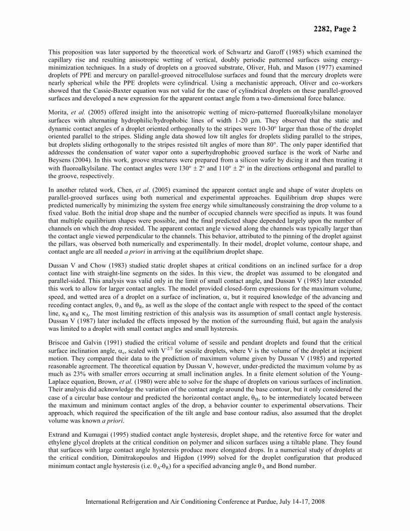
This proposition was later supported by the theoretical work of Schwartz and Garoff (1985) which examined the capillary rise and resulting anisotropic wetting of vertical, doubly periodic patterned surfaces using energy-minimization techniques. In a study of droplets on a grooved substrate, Oliver, Huh, and Mason (1977) examined droplets of PPE and mercury on parallel-grooved nitrocellulose surfaces and found that the mercury droplets were nearly spherical while the PPE droplets were cylindrical. Using a mechanistic approach, Oliver and co-workers showed that the Cassie-Baxter equation was not valid for the case of cylindrical droplets on these parallel-grooved surfaces and developed a new expression for the apparent contact angle from a two-dimensional force balance.
Morita, et al. (2005) offered insight into the anisotropic wetting of micro-patterned fluoroalkylsilane monolayer surfaces with alternating hydrophilic/hydrophobic lines of width 1-20 m. They observed that the static and dynamic contact angles of a droplet oriented orthogonally to the stripes were 10-30 larger than those of the droplet oriented parallel to the stripes. Sliding angle data showed low tilt angles for droplets sliding parallel to the stripes, but droplets sliding orthogonally to the stripes resisted tilt angles of more than 80 . The only paper identified that addresses the condensation of water vapor onto a superhydrophobic grooved surface is the work of Narhe and Beysens (2004). In this work, groove structures were prepared from a silicon wafer by dicing it and then treating itwith fluoroalkylsilane. The contact angles were 130 2 and 110 2 in the directions orthogonal and parallel to the groove, respectively.
In another related work, Chen, et al. (2005) examined the apparent contact angle and shape of water droplets on parallel-grooved surfaces using both numerical and experimental approaches. Equilibrium drop shapes were predicted numerically by minimizing the system free energy while simultaneously constraining the drop volume to a fixed value. Both the initial drop shape and the number of occupied channels were specified as inputs. It was found that multiple equilibrium shapes were possible, and the final predicted shape depended largely upon the number of channels on which the drop resided. The apparent contact angle viewed along the channels was typically larger than the contact angle viewed perpendicular to the channels. This behavior, attributed to the pinning of the droplet against the pillars, was observed both numerically and experimentally. In their model, droplet volume, contour shape, and contact angle are all needed a priori in arriving at the equilibrium droplet shape.
Dussan V and Chow (1983) studied static droplet shapes at critical conditions on an inclined surface for a drop contact line with straight-line segments on the sides. In this view, the droplet was assumed to be elongated and parallel-sided. This analysis was valid only in the limit of small contact angle, and Dussan V (1985) later extended this work to allow for larger contact angles. The model provided closed-form expressions for the maximum volume, speed, and wetted area of a droplet on a surface of inclination, , but it required knowledge of the advancing and receding contact angles, A and R, as well as the slope of the contact angle with respect to the speed of the contact line, R and A. The most limiting restriction of this analysis was its assumption of small contact angle hysteresis. Dussan V (1987) later included the effects imposed by the motion of the surrounding fluid, but again the analysis was limited to a droplet with small contact angles and small hysteresis.
Briscoe and Galvin (1991) studied the critical volume of sessile and pendant droplets and found that the critical surface inclination angle, c, scaled with V-2/3 for sessile droplets, where V is the volume of the droplet at incipient motion. They compared their data to the prediction of maximum volume given by Dussan V (1985) and reported reasonable agreement. The theoretical equation by Dussan V, however, under-predicted the maximum volume by as much as 23% with smaller errors occurring at small inclination angles. In a finite element solution of the Young-Laplace equation, Brown, et al. (1980) were able to solve for the shape of droplets on various surfaces of inclination. Their analysis did acknowledge the variation of the contact angle around the base contour, but it only considered the case of a circular base contour and predicted the horizontal contact angle, H, to be intermediately located between the maximum and minimum contact angles of the drop, a behavior counter to experimental observations. Their approach, which required the specification of the tilt angle and base contour radius, also assumed that the droplet volume was known a priori.
Extrand and Kumagai (1995) studied contact angle hysteresis, droplet shape, and the retentive force for water and ethylene glycol droplets at the critical condition on polymer and silicon surfaces using a tiltable plane. They found that surfaces with large contact angle hysteresis produce more elongated drops. In a numerical study of droplets at the critical condition, Dimitrakopoulos and Higdon (1999) solved for the droplet configuration that produced minimum contact angle hysteresis (i.e. A- R) for a specified advancing angle A and Bond number.

2282, Page 3
International Refrigeration and Air Conditioning Conference at Purdue, July 14-17, 2008
In two recent reports by El Sherbini and Jacobi (2004a,b), droplet shapes were studied experimentally. The droplet shape was approximated using a ‘two-circle method’ in which the droplet profile is fitted with two circles sharing a common tangent at the apex of the droplet. The volume was then calculated by integrating the profile around the circumference of the base. This method was found to accurately predict the volume of droplets, knowing only the contact angle and shape of the three-phase contact line. Their work was developed for conventional surfaces of homogeneous roughness. In the work of El Sherbini and Jacobi, the base contour was assumed to be elliptical and continuous. Again, observations of droplets on surfaces with micro-etched grooves indicate that the modeling approach used on conventional surfaces does not readily extend to topographically anisotropic surfaces.
Understanding the behavior, shape, and size of water droplets is the key to understanding droplet retention on a surface. Significant research has already been reported on analytical and numerical methods for calculating droplet volume on smooth surfaces as well as homogeneously rough surfaces. However, no calculation method was found that specifically addresses the volume calculation of condensed water droplets on parallel, micro-grooved surfaces. The inability of existing models to satisfactorily calculate the droplet volume is largely ascribed to the unusual variation of the apparent contact angle around the base of the drop, the discontinuity of the three-phase contact line, and the elongated, parallel-sided droplet shape. Therefore, if functional topography is to be useful as a method for manipulating wettability for the purpose of controlling condensation or water drainage on heat transfer surfaces,then new models and methods are needed.
2. EXPERIMENTAL THEORY AND METHODSThe contact angle that a liquid droplet forms on a horizontal surface is described by the classical equation by Young (1855),
LV
SLSVcos (1)
where SV , SL, and LV are the interfacial free energies per unit area of the solid-vapor, solid-liquid, and liquid-vapor interfaces, respectively. The specific contact angle that a water droplet forms on a surface has long been used as a gauge of the hydrophobicity of the surface. However, depending on how the water droplet forms on a rough surface, at least two different wetting regimes can exist. The first form, known as the “wetted surface,” occurs when the water droplet completely fills the surface asperities. This particular wetting regime, which may result from melting frost or condensing water vapor, is usually described by Wenzel’s theory of wetting (1936). The second type known as the “composite surface” occurs when the droplet is suspended over the asperities, leaving air trapped beneath it. This form of wetting frequently occurs when the droplet is injected by syringe onto a surface having sufficiently small surface features. “Composite surfaces” are described by Cassie-Baxter’s theory of wetting (1944). By themselves, large contact angles associated with a hydrophobic surface do not ensure that a surface easily sheds water. Therefore, the sliding angle is a useful criterion when evaluating the water drainage behavior of surfaces. The sliding angle is the critical angle for a water droplet of known mass to first begin sliding down an inclined surface.
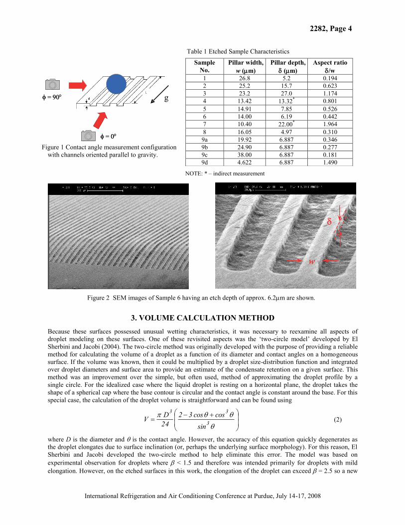
The objective of this research was to develop a new method for calculating the volume of water droplets on parallel-grooved aluminum surfaces, and as such it was important to understand how such modeling might depend on the wetting modes described by the Wenzel and Cassie-Baxter models. To explore the Wenzel mode of wetting (the focus of this research), a Peltier stage was utilized to condense water vapor onto the micro-grooved surface generating droplets that wet the surface. Still images were obtained using a charge coupled device (CCD) camera around the base of the droplet and analyzed to obtain the apparent contact angle and dimensions of the droplet. The grooves were aligned with gravity because that configuration appeared to be the most promising for promotingdrainage (see Fig. 1). The micro-grooved surfaces were produced using standard photolithographic practices and a reactive ion etching technique described in Sommers and Jacobi (2006). Parallel channels approximately tens of microns in width and depth, running the length of the surface, were etched into plates of aluminum alloy 1100 (99.9% pure Al), 63.5 mm by 63.5 mm by 3.2 mm in size. On the backs of the plates, two holes were drilled to a depth of approximately 2.5 mm and threaded to allow for backside mounting to a Peltier cooling stage. The plates had an average roughness, Ra, of 25-35 nm prior to etching. After undergoing etching, the plates were analyzed using a Cambridge S-360 scanning electron microscope and an Alpha-Step profilometer to determine the surface geometry accurately. Scanning electron microscope images of one of these surfaces are included below in Figure 2. (A list of all manufactured surfaces can be found in Table 1.)
2282, Page 4
International Refrigeration and Air Conditioning Conference at Purdue, July 14-17, 2008
Table 1 Etched Sample Characteristics
Figure 1 Contact angle measurement configuration
with channels oriented parallel to gravity.
NOTE: * – indirect measurement
Figure 2 SEM images of Sample 6 having an etch depth of approx. 6.2 m are shown.
3. VOLUME CALCULATION METHOD
Because these surfaces possessed unusual wetting characteristics, it was necessary to reexamine all aspects of droplet modeling on these surfaces. One of these revisited aspects was the ‘two-circle model’ developed by El Sherbini and Jacobi (2004). The two-circle method was originally developed with the purpose of providing a reliable method for calculating the volume of a droplet as a function of its diameter and contact angles on a homogeneous surface. If the volume was known, then it could be multiplied by a droplet size-distribution function and integrated over droplet diameters and surface area to provide an estimate of the condensate retention on a given surface. This method was an improvement over the simple, but often used, method of approximating the droplet profile by a single circle. For the idealized case where the liquid droplet is resting on a horizontal plane, the droplet takes the shape of a spherical cap where the base contour is circular and the contact angle is constant around the base. For this special case, the calculation of the droplet volume is straightforward and can be found using
3
33
sincoscos32
24DV
(2)
where D is the diameter and is the contact angle. However, the accuracy of this equation quickly degenerates as the droplet elongates due to surface inclination (or, perhaps the underlying surface morphology). For this reason, ElSherbini and Jacobi developed the two-circle method to help eliminate this error. The model was based on experimental observation for droplets where < 1.5 and therefore was intended primarily for droplets with mild elongation. However, on the etched surfaces in this work, the elongation of the droplet can exceed = 2.5 so a new
Sample No.
Pillar width, w ( m)
Pillar depth, ( m)
Aspect ratio/w
1 26.8 5.2 0.1942 25.2 15.7 0.6233 23.2 27.0 1.1744 13.42 13.32* 0.8015 14.91 7.85 0.5266 14.00 6.19 0.4427 10.40 22.00* 1.9648 16.05 4.97 0.3109a 19.92 6.887 0.3469b 24.90 6.887 0.2779c 38.00 6.887 0.1819d 4.622 6.887 1.490
g= 90
= 0
g= 90
= 0
w

2282, Page 5
International Refrigeration and Air Conditioning Conference at Purdue, July 14-17, 2008
method for calculating the droplet volume was considered. In this method, the droplet is treated as a cylindricalelement, and the volume is found by integrating the cross-sectional area down the length of the droplet rather than by the sweeping around the periphery of the droplet and integrating droplet profiles taken at all azimuthal angles. The advantage of using this method over the two-circle method is that it utilizes the wetting behavior of droplets on these micro-structured surfaces and therefore does not require a priori information about the droplet base contour shape or azimuthal contact angle variation. (Note: This information is provided as inputs in the two-circle method.)
The idea behind this aforementioned extrusion method is relatively simple. As shown in Figure 3, the droplet is split into two regions (red and blue), each of which is then further subdivided into two smaller components. Regions 1 and 2 are fit by a teardrop profile,
22
1xcc
xy (3)
where c1 and c2 represent constants to be determined later, and regions 3 and 4 are fit by a circle having the form
2h
21 xLxRy (4)
where represents the height of the circle’s center above the surface and xh represents the lateral offset of the circle’s center (or, the x-component of the distance from the midpoint of the base length to the center).
In this method, the variables h, L, 1, and 2 are supplied by the user and everything else is calculated including xh.The constants appearing in the teardrop profile, c1 and c2, are found by matching the height of the droplet, h, and the apparent contact angle, 2. The first boundary condition is found by taking the derivative of the teardrop function
22
1
22
21 xc
1cxxcc
1dxdy
(5)
The slope is then related to the contact angle by
1
22 c
ctandx
dy(6)
which is the first specified boundary condition. The second boundary condition is found by substituting x = (L+xh)into the original function, Eq. (3), to get
2h2
1
h xLccxLh . (7)
The constants in the circular profile, and R1, are found similarly by matching the droplet height h and contact angle 1 with the specified inputs. The height is fixed by recognizing that
1Rh (8)and the contact angle is fixed according to
1
hR
xLcos where 21 (9)
as shown in Figure 4.
Figure 3 The droplet profile is approximated using both a circle and a teardrop shape.
2282, Page 6
International Refrigeration and Air Conditioning Conference at Purdue, July 14-17, 2008
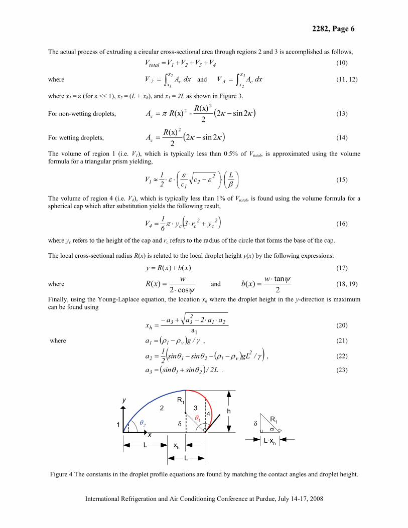
The actual process of extruding a circular cross-sectional area through regions 2 and 3 is accomplished as follows,
4321total VVVVV (10)
where2
1
x
x c2 dxAV
and3
2
x
x c3 dxAV
(11, 12)
where x1 = (for << 1), x2 = (L + xh), and x3 = 2L as shown in Figure 3.
For non-wetting droplets, 2sin22(x) - (x)
22 RRAc (13)
For wetting droplets, 2sin22(x) 2RAc (14)
The volume of region 1 (i.e. V1), which is typically less than 0.5% of Vtotal, is approximated using the volume formula for a triangular prism yielding,
Lcc21V 2
21
1 (15)
The volume of region 4 (i.e. V4), which is typically less than 1% of Vtotal, is found using the volume formula for a spherical cap which after substitution yields the following result,
2c
2cc4 yr3y6
1V (16)
where yc refers to the height of the cap and rc refers to the radius of the circle that forms the base of the cap.
The local cross-sectional radius R(x) is related to the local droplet height y(x) by the following expressions:
)()( xbxRy (17)
wherecos2
)( wxR and 2tan)( wxb (18, 19)
Finally, using the Young-Laplace equation, the location xh where the droplet height in the y-direction is maximum can be found using
1
a
21233
haa2aa
x (20)
where /ga vl1 , (21)
/gLsinsin21a 2
vl212 , (22)
L2/sinsina 213 . (23)
1
2 34 h
R1
L-xh
R1
L xh
L
1
x
y
Figure 4 The constants in the droplet profile equations are found by matching the contact angles and droplet height.

2282, Page 7
International Refrigeration and Air Conditioning Conference at Purdue, July 14-17, 2008
4. RESULTS AND DISCUSSION
For water droplets condensed on these micro-structured surfaces, this method only requires geometrical data taken from two droplet images (i.e. = 0 and = 90 ) and typically yields an accuracy that is similar to, or better than, the two-circle method. A comparison between these two methods is shown below in Figure 5. It should be pointed out that the experimental droplet volume data represent water droplets condensed on sample 2 and therefore the Wenzel mode of wetting. Because these volume data were determined by absorption and the subsequent direct weighing of the droplet on a high-precision balance, these experimental data are not as accurate as those obtained by using a micro-syringe. The maximum uncertainty of the experimental data themselves was 0.5 L. Nonetheless, Figure 5 highlights the ability of this new method to determine the droplet volume from measured geometrical parameters and compares these results to the two-circle method developed by El Sherbini and Jacobi (2004). It should be noted that for these data, the two-circle method generated eleven cases where the percent error was greater than or equal to 10%. By comparison, this new extrusion-based technique only produced four cases where the percent error equaled or exceeded 10%. Because water droplets on these micro-structured surfaces tend to be parallel-sided and are often highly elongated, this method appears to hold tremendous promise as a non-intrusive means of determining the droplet volume. It requires only a few simple inputs which can be gleaned from images of the droplet at = 0 and = 90 — namely, the droplet major axis, minor axis, height, and the apparent contact angles at both the advancing and receding fronts of the droplet. It should be noted, however, that this new method of finding the droplet volume tacitly relies upon the parallel-sided nature of these droplets and may not work as well for droplets on a conventional surface.
To explore the Cassie-Baxter mode of wetting, a micro-syringe was used to inject droplets onto the surface. These data were collected by examining 18 different composite water droplets (shown in Fig. 6) injected on sample 5.Droplet volumes from 10 L to 50 L were investigated. Because these droplets did not fully wet the micro-channels, the parallel-sided base contour shape of the droplets was not fully realized. As a result, this new method for calculating the droplet volume underpredicted the droplet volume on average by 18.9%, whereas the two-circlemethod tended to overpredict the droplet volume. The average error associated with using the two-circle method for these droplets was 14.4%. Thus, for droplets departing from the parallel-sided base contour shape, the two-circle method developed by El Sherbini and Jacobi (2004) provides slightly more accurate results.
0
5
10
15
20
25
0 5 10 15 20 25
new extrusion methodEl Sherbini and Jacobi (2004)
Calc
. Vol
(L)
Exp. Vol ( L)Figure 5 Comparison of the two-circle and extrusion-based Figure 6 A 10 L composite droplet image thatdroplet volume calculation methods for condensed droplets illustrates the five required inputs in the model
height
width
max
length
1 2
Channels out of page (i.e. = 0 )
Channels parallel to length (i.e. = 90 ) +10%
- 10%

2282, Page 8
International Refrigeration and Air Conditioning Conference at Purdue, July 14-17, 2008
5. CONCLUSIONSIn this study, a new integration-based method was developed and then examined for the calculation of the volume of water droplets condensed on aluminum surfaces containing parallel grooves tens of microns in width and depth.These surfaces have been shown to reduce the critical droplet size needed for sliding and exhibit improved water shedding characteristics. This new model which tacitly relies on the parallel-sided nature of condensed droplets on these surfaces was shown to predict the droplet volume to within 10% of the true value for 88% of the droplets examined. For droplets injected onto the surface by micro-syringe, the parallel-sided base contour shape is less pronounced, and the method was found to be less accurate. The inputs to this model which include the droplet major axis, minor axis, height, and two contact angles are taken directly from two droplet images. The calculation method presented in this work is useful for estimating the volume of retained water droplets on micro-grooved surfaces where the surface micro-channels are aligned parallel to gravity and both heat and mass transfer occur.
NOMENCLATUREAc droplet cross sectional area (m2) Greek Symbols:g acceleration of gravity (m s-2) azimuthal angle (°)h droplet height (m-1) droplet aspect ratio (-)L half of the droplet major axis (m) surface tension (N m-1)V droplet volume (m3) 1 contact angle at =0° (°)w half of the droplet minor axis (m) 2 contact angle at =180° (°)xh location where droplet height is maximum (m) density (kg m-3)
REFERENCESBriscoe, B.J., Galvin, K.P., 1991, “The sliding of sessile and pendent droplets: The critical condition,” Colloids and Surfaces
52, pp. 219-229.
Brown, R.A., Orr, F.M. Jr., Scriven, L.E., 1980, “Static drop on an inclined plate: analysis by the finite element method,” J. Colloid Interface Sci. 73(1), pp. 76-87.
Chen, Y., He, B., Lee, J., Patankar, N.A., 2005, “Anisotropy in the wetting of rough surfaces,” J. Colloid Interface Sci. 281,pp.458-464.
Dimitrakopoulos, P., Higdon, J.J.L., 1999, “On the gravitational displacement of three-dimensional fluid droplets from inclined solid surfaces,” J. Fluid Mech. 395, pp.181-209.
Dussan V., E.B., Chow, R. T.-P., 1983, “On the ability of drops or bubbles to stick to non-horizontal surfaces of solids,” J. Fluid Mechanics 137, pp. 1-29.
ElSherbini, A.I., Jacobi, A.M., 2004, “Liquid drops on vertical and inclined surfaces: I. An experimental study of drop geometry,” J. Colloid Interface Sci. 273, pp. 556-565.
ElSherbini, A.I., Jacobi, A.M., 2004, “Liquid drops on vertical and inclined surfaces: II. A method for approximating drop shapes,” J. Colloid Interface Sci. 273, pp. 566-575.
Extrand, C.W., Kumagai, Y., 1995, “Liquid drops on an inclined plane: the relation between contact angles, drop shape, and retentive force,” J. Colloid Interface Sci. 170, pp. 515-521.
Morita, M., Koga, T., Otsuka, H., Takahara, A., 2005, “Macroscopic-wetting anisotropy on the line-patterned surface of fluoroalkylsilane monolayers,” Langmuir 21, pp. 911-918.
Narhe, R.D., Beysens, D.A., 2004, “Nucleation and growth on a superhydrophobic grooved surface,” Phys. Rev. Letters 93(7), Art. No. 076103.
Neumann, A.W., Good, R.J., 1972, “Thermodynamics of contact angles,” J. Colloid Interface Sci. 38(2), pp.341-358.
Oliver, J.F., Huh, C., Mason, S.G., 1977, “The apparent contact angle of liquids on finely-grooved solid surfaces- A SEM study,” J. Adhesion 8, pp. 223-234.
Schwartz, L., Garoff, S., 1985, “Contact angle hysteresis on heterogeneous surfaces,” Langmuir 1, pp. 219-230.
Sommers, A.D, Jacobi, A.M., 2006, “Creating micro-scale surface topology to achieve anisotropic wettability on an aluminum surface,” Journal of Micromechanics & Microengineering, 16(8), pp. 1571-1578.


