CAISSON SHAFT SYSTEM - Marshalls CPM · CAISSON SHAFT SYSTEM Issue 4d – Dec 2016 Registered...
14
CAISSON SHAFT SYSTEM Issue 4d – Dec 2016 Registered Office: CPM Group Ltd, Head Office, Mells Road, Mells, Frome, Somerset BA11 3PD Registered in England 1005164 CAISSON SHAFT SYSTEM Installation Guide
Transcript of CAISSON SHAFT SYSTEM - Marshalls CPM · CAISSON SHAFT SYSTEM Issue 4d – Dec 2016 Registered...

CAISSON SHAFT SYSTEM Issue 4d – Dec 2016
Registered Office: CPM Group Ltd, Head Office, Mells Road, Mells, Frome, Somerset BA11 3PD Registered in England 1005164
CAISSON SHAFT SYSTEM
Installation Guide

CAISSON SHAFT SYSTEM Issue 4d – Dec 2016
Registered Office: CPM Group Ltd, Head Office, Mells Road, Mells, Frome, Somerset BA11 3PD Registered in England 1005164
INSTALLATION GUIDE FOR DN2000 TO DN3660 UNITS – PLATE JOINTING SYSTEM This guide is to be used for the Installation of CPM Group Ltd caisson shaft units which use a plate jointing system. GENERAL Health and Safety Prior to commencement of any work, a full Risk Assessment should be carried out and a bespoke Safe System of Work developed.
Components
1. Base unit - comprising of a 0.25m effective depth cutting shoe attached to bottom ring (with nominal 20mm overbreak as standard on DN2000 to DN3000 sized units and nominal 30mm overbreak as standard on DN3660 & DN4000 sized units). Note: cutting shoes supplied loose on DN3660 and DN4000 units for site fitting to first ring (note: DN4000 cutting shoe is supplied to site in two parts).
2. Precast concrete caisson units produced in 1.00m, 0.75m and 0.50m depths (0.50m depth unit
not available in DN4000 size). 3. Mild steel lifting brackets and M20 x 40mm long bolts (see Appendix A – Fig A1).
4. Joint sealing strip (TA 200 - Butyl Sealing Strip) – best stored inside prior to use as
workability of material reduces if the material is exposed to cold conditions.
5. 6mm mild steel joint connecting plates, discs, M20 x 40mm long bolts and 50mm square x 6mm thick washers (see Appendix A – Fig A2).
6. Precast concrete heavy duty cover slabs to BS5911-3 suitable for main road loading with
675sq access as standard (other sizes of access are available to order).
Weights and Dimensions See appendix B Cutting Shoe Usually supplied fitted to a 0.50m deep caisson shaft unit (Note: DN3660 is a two part shoe supplied loose to site) being 0.75m overall depth and providing a nominal 20mm or 30mm overbreak dependent on shaft diameter (alternative overbreaks can be made to order/shoe can be fitted to other depth units). Shafts Wet cast units to reduce friction (joint profile dependent on diameter).

CAISSON SHAFT SYSTEM Issue 4d – Dec 2016
Registered Office: CPM Group Ltd, Head Office, Mells Road, Mells, Frome, Somerset BA11 3PD Registered in England 1005164
Installation Procedure – DN2000 to DN3660 Units 1. Components
1.1 Check delivery notes to ensure that all components are available before work
commences on site.
1.2 All ancillary components should be stored in a secure area. The caisson sealant must not be stacked so as to become compressed or distorted before use and is best kept indoors up until the point of use.
2 Lifting
2.1 Ensure that suitable plant is available to accomplish necessary reach and lift
(see Appendix B for standard product sizes and weights). 2.2 Use the three specially designed and tested lifting brackets and 6No. M20 x 40mm
bolts supplied (see Appendix A – Fig A1) for lifting of each individual shaft ring.
UNDER NO CIRCUMSTANCES MUST THE JOINT CONNECTION PLATES BE USED FOR LIFTING.
2.3 Use adequate length lifting chains, or in combination with a lifting frame. The
maximum angle from the vertical for chains should be no more than 30° UNDER NO CIRCUMSTANCES MUST THE LIFTING BRACKETS BE USED FOR
THE TRANSPORTATION OF UNITS ACROSS THE SITE.

CAISSON SHAFT SYSTEM Issue 4d – Dec 2016
Registered Office: CPM Group Ltd, Head Office, Mells Road, Mells, Frome, Somerset BA11 3PD Registered in England 1005164
3 Jointing
3.1 Ensure that the jointing surfaces are clean and dry. Place the sealing strip centrally onto the top joint (see appendix C for further details) and remove any sealant separation paper. Mitre all joints in the strip where required to produce a continuous seal. Note: All joints must be clean and dry before jointing if a watertight shaft is to be formed.
3.2 Lift the next shaft unit, clean the underside jointing face, align the jointing pockets
then carefully lower it onto the previous unit and allow the sealant to compress (usually until there is a nominal 5mm joint gap). Additional kentledge may be applied to assist and speed up this process - ensuring that the top joint profile is protected at all times from damage.
3.3 Fit the joint connecting plates (3No for DN2000 & DN2400 units and 6No for
DN2740 to DN3660 units) to the lower unit using the M20 x 40mm bolts and washers provided, through the smaller 21mm diameter hole of the bracket and tighten finger tight (see Appendix A – Fig A2).
3.4 Rotate the eccentric discs in each upper 51mm diameter hole of the joint
connecting plate and fix in place using further M20 x 40mm bolts and square washer.
3.5 Tighten all M20 x 40mm joint connecting plate bolts. 3.6 The prime function of these plates is to hold the units together during the shaft
sinking process so as to prevent a joint opening up.

CAISSON SHAFT SYSTEM Issue 4d – Dec 2016
Registered Office: CPM Group Ltd, Head Office, Mells Road, Mells, Frome, Somerset BA11 3PD Registered in England 1005164
4 Installation
4.1 Ensure that the area to be excavated is clear of all buried services and
that special precautions are taken with regard overhead services.
4.2 Excavate a pit at least 1.00m deep and 0.50m greater than the overall diameter of the cutting shoe in which to cast a 250mm wide choker ring.
4.3 Set and level the first unit with the cutting shoe attached (base unit) into the
excavation. It is preferable to align the unit so that jointing plate positions are kept clear of intended pipe runs.
4.4 Surround the unit and cutting shoe with typically 12mm of polystyrene sheet and fix
into place with masking tape to the required depth of the choker ring (ensuring that no gaps are left. If one unit with the cutting shoe is not of sufficient depth, then add an additional unit as detailed in section 3 above.
NOTE: Where the caisson is to be used as an access for micro-tunnelling or pipe jacking, it
will be advantageous to centralize the tunnel or pipe jack on a joint between 1.00m deep units. Also inlet/outlet pipes should be positioned to avoid joint connecting plates and minimize loss in overall integrity. A suitably designed thrust wall may also be required.
4.5 An insitu concrete choker ring of nominal dimensions 1.00m deep and 250mm wide
formed between the wrapped units (polystyrene or similar) and the excavation may now be cast using ST4 concrete. Depending on the stability of the ground, it may be prudent to use a light mesh fabric to reinforce the choker ring.
4.6 Normally sinking of the caisson may commence the following day, having first
dissolved the polystyrene with an appropriate environmentally friendly solvent.

CAISSON SHAFT SYSTEM Issue 4d – Dec 2016
Registered Office: CPM Group Ltd, Head Office, Mells Road, Mells, Frome, Somerset BA11 3PD Registered in England 1005164
4.7 The insitu concrete choker ring acts not only as a work platform and ground
support, but also as a guide for sinking the subsequent caisson units. By observing the uniformity of the gap between the caisson units and the choker ring, it will be possible to determine how vertical the shaft is being constructed. If the shaft tries to go off the vertical, apply kentledge or load on the high side until verticality is regained (ensuring that the joint profile is protected).
4.8 To continue sinking the caisson, excavation inside the units may be achieved for
example using a hydraulically operated grab, or a rotating clamshell. In soft ground the caissons may sink under their own weight. In denser ground it may be necessary to provide kentledge or load (while providing protection to the joint surface). Jointing of additional caisson units as 3.1 thru 3.5 above, continuing until the required depth of construction is achieved.
4.9 When the shaft is to be used for tunnelling, it normally necessary to sink the
lowermost unit at least 700mm below the tunnel invert. 4.10 A ST4 insitu concrete base may then be cast manually if conditions are dry, or by
tremi tube if the shaft is flooded. In the latter case, on no account pump out the shaft until the base concrete has matured sufficiently.
Fitting of steel cutting shoe when supplied separate (not fitted to bottom ring);-
Fitting together of two part steel cutting shoe (DN3660);-
Using the 6No M16 x 70mm bolt, nut and washer sets – bolt the two sections together prior to fitting to bottom ring.
5 Cover Slab Installation
5.1 Clean and dry the groove joint on top of the final caisson shaft unit and apply sufficient strips of sealant to bed the cover slab.
5.2 Align the access position in the slab appropriately and lower the slab centrally onto
the shaft, ensuring uniform compression of the sealant.

CAISSON SHAFT SYSTEM Issue 4d – Dec 2016
Registered Office: CPM Group Ltd, Head Office, Mells Road, Mells, Frome, Somerset BA11 3PD Registered in England 1005164
INSTALLATION GUIDE FOR DN4000 UNITS (2 SEGMENTS) – PLATE JOINTING SYSTEM This guide is to be used for the Installation of CPM Group Ltd Caisson shaft units which use a plate jointing system. GENERAL Health and Safety Prior to commencement of any work, a full Risk Assessment should be carried out and a bespoke Safe System of Work developed.
Components
1. A nominal 0.25m overall deep cutting shoe with nominal 30mm overbreak (2 part unit supplied loose).
2. Precast concrete caisson units produced in 1.00m and 0.75m depths. 3. Mild steel lifting brackets and M20 x 40mm long bolts (see Appendix A – Fig A1).
4. Joint sealing strip (TA200 Butyl Sealing Strip – 2 sizes required).
5. 6mm mild steel joint connecting plates, discs, M20 x 40mm long bolts and 50mm square x
6mm thick washers (see Appendix A – Fig A2).
6. Segment connecting nuts, 200mm long 24mm Ø bolts, nuts and washers.
7. Precast concrete two part heavy duty cover slab suitable for main road loading with 675sq access as standard (other sizes of access are available to order).
Weights and Dimensions See appendix B Cutting Shoe These are manufactured and supplied loose (for site fitting) and provide a 30mm overbreak as standard – supplied in two halves for bolting together on site. Shafts Shaft units are manufactured in 2 halves for transport purposes (to be jointed together on site). Products are wet cast reinforced units to reduce friction with.

CAISSON SHAFT SYSTEM Issue 4d – Dec 2016
Registered Office: CPM Group Ltd, Head Office, Mells Road, Mells, Frome, Somerset BA11 3PD Registered in England 1005164
Installation Procedure - DN4000 Units
1. Components
1.1 Check delivery notes to ensure that all components are available before work
commences on site. 1.2 All ancillary components should be stored in a secure area. The caisson butyl sealant
must not be stacked so as to become compressed or distorted before use and is best kept indoors up until the point of use.
2. Lifting
2.1 Ensure that suitable plant is available to accomplish necessary reach and lift
(see Appendix B for standard product sizes and weights).
2.2 Use the three specially designed and tested lifting brackets and 6 No M20 x 40mm bolts supplied (see Appendix A – Fig A1). Three lifting brackets are required for each half or complete ring (note – middle chain will require shortening when lifting individual half sections).UNDER NO CIRCUMSTANCES MUST THE JOINT CONNECTION PLATES BE USED FOR LIFTING.
2.3 Use adequate length lifting chains, or in combination with a lifting frame. The
maximum angle from the vertical for chains should be no more than 30°. UNDER NO CIRCUMSTANCES MUST THE LIFTING BRACKETS BE USED FOR THE TRANSPORTATION OF UNITS ACROSS THE SITE
3. Jointing Half Segments
Each caisson shaft unit is supplied in 2 half sections. These are jointed together into a complete ring at ground level (prior to lifting into excavation).
3.1 Prepare a level working area, some 5.5m square. It is absolutely essential that the
designated area is flat. 3.2 Set up the first half segment on timber bearers, clear of the ground. Check for level
and plumb and adjust if necessary. 3.3 Set up the second half segment on timber bearers on a level with the first segment,
maintaining a gap of approx. 150mm between the segments. Keep the crane attached to assist with the final jointing operation.
3.4 Apply 25 x 12mm butyl sealant to the vertical grooves of both segments (lap around
upper and lower corners to ensure sealing with horizontal joint sealant when laid). 3.5 Offer up the second segment to the first with the crane just taking the weight (it is
essential the crane takes the load until such time as the jointing operation has been completed and the whole unit is evenly supported from below). Engage all
of the 200 x 24mm Ø bolts provided and pull the segments together by tightening each
bolt gradually and in turn ensuring that the two segments remain level (there are 6 bolts for the 1.00m deep units and 4 bolts for the 0.75m units). The bolts should be tightened to compress the seal to give a 6-8mm joint gap. A maximum torque of 125Nm should be applied. If due to adversely cold weather conditions the seal cannot be compressed within this torque limit, apply gentle heat to the seal to soften it.

CAISSON SHAFT SYSTEM Issue 4d – Dec 2016
Registered Office: CPM Group Ltd, Head Office, Mells Road, Mells, Frome, Somerset BA11 3PD Registered in England 1005164
3.6 Once all the bolts are tightened to the correct torque, the crane may be released. The
unit is now ready for use.
DN4000 Segment Connection Details:
172
110 215
115
110 215
85
110
75
25 x 12 Butyl
Rubber Seal
Cast-in threaded socket
Connecting Bolt 200mm Overall
25Ø x 100mm shank, 2x24mm
Thread x 50mm ong
Cast-in plate JO
INT
FA
CE
29Ø Tube
3No bolt boxes in 1.00m deep unit, boxes set at
215mm, 600mm and 855mm from top of unit.
2No bolt boxes in 0.75m deep unit boxes set at
215mm and 600mm from top of unit.
ElevationPlan
Fitting together of two part steel cutting shoe;-
Using the 6No M16 x 70mm bolt, nut and washer sets – bolt the two sections together prior to fitting to bottom ring.
CAISSON SHAFT SYSTEM Issue 4d – Dec 2016
Registered Office: CPM Group Ltd, Head Office, Mells Road, Mells, Frome, Somerset BA11 3PD Registered in England 1005164
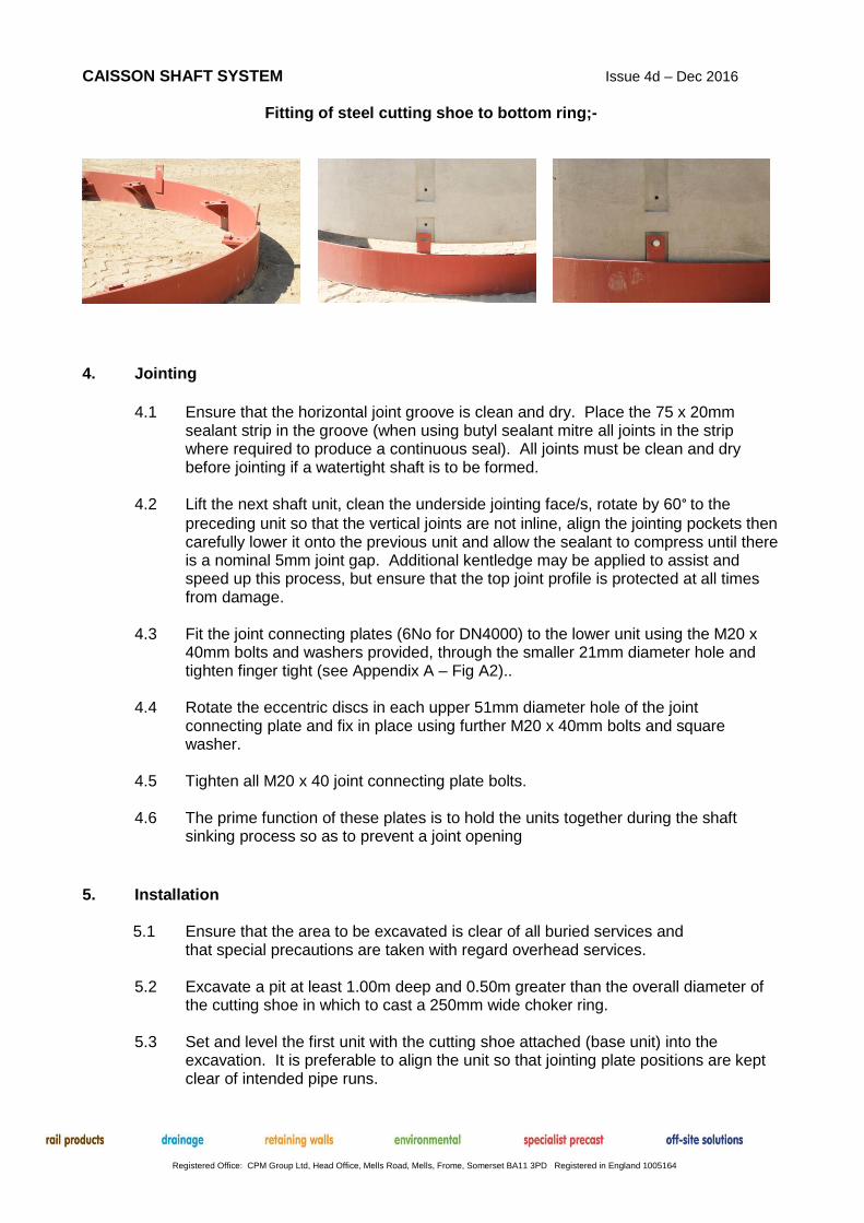
Fitting of steel cutting shoe to bottom ring;-
4. Jointing
4.1 Ensure that the horizontal joint groove is clean and dry. Place the 75 x 20mm
sealant strip in the groove (when using butyl sealant mitre all joints in the strip where required to produce a continuous seal). All joints must be clean and dry before jointing if a watertight shaft is to be formed.
4.2 Lift the next shaft unit, clean the underside jointing face/s, rotate by 60° to the
preceding unit so that the vertical joints are not inline, align the jointing pockets then carefully lower it onto the previous unit and allow the sealant to compress until there is a nominal 5mm joint gap. Additional kentledge may be applied to assist and speed up this process, but ensure that the top joint profile is protected at all times from damage.
4.3 Fit the joint connecting plates (6No for DN4000) to the lower unit using the M20 x
40mm bolts and washers provided, through the smaller 21mm diameter hole and tighten finger tight (see Appendix A – Fig A2)..
4.4 Rotate the eccentric discs in each upper 51mm diameter hole of the joint
connecting plate and fix in place using further M20 x 40mm bolts and square washer.
4.5 Tighten all M20 x 40 joint connecting plate bolts. 4.6 The prime function of these plates is to hold the units together during the shaft
sinking process so as to prevent a joint opening
5. Installation
5.1 Ensure that the area to be excavated is clear of all buried services and
that special precautions are taken with regard overhead services.
5.2 Excavate a pit at least 1.00m deep and 0.50m greater than the overall diameter of the cutting shoe in which to cast a 250mm wide choker ring.
5.3 Set and level the first unit with the cutting shoe attached (base unit) into the
excavation. It is preferable to align the unit so that jointing plate positions are kept clear of intended pipe runs.

CAISSON SHAFT SYSTEM Issue 4d – Dec 2016
Registered Office: CPM Group Ltd, Head Office, Mells Road, Mells, Frome, Somerset BA11 3PD Registered in England 1005164
5.4 Surround the unit and cutting shoe with typically 12mm of polystyrene sheet and fix into place with masking tape, ensuring that no gaps are left, to the required depth of the choker ring. If one unit with the cutting shoe is not of sufficient depth, then add an additional unit as detailed in section 3 above.
NOTE: Where the caisson is to be used as an access for micro-tunnelling or pipe jacking, it
will be advantageous to centralize the tunnel or pipe jack on a joint between 1.00m deep units. Also inlet/outlet pipes should be positioned to avoid joint connecting plates and minimize loss in overall integrity. A suitably designed thrust wall will also be required.
5.5 An insitu concrete choker ring of nominal dimensions 1.00m deep and 250mm wide
formed between the wrapped units (polystyrene or similar) and the excavation may now be cast using ST4 concrete. Depending on the stability of the ground, it may be prudent to use a light mesh fabric to reinforce the choker ring.
5.9 Normally sinking of the caisson may commence the following day, having first dissolved the polystyrene with an appropriate environmentally friendly solvent.
5.10 The insitu concrete choker ring acts not only as a work platform and ground
support, but also as a guide for sinking the subsequent caisson units. By observing the uniformity of the gap between the caisson units and the choker ring, it will be possible to determine how vertical the shaft is being constructed. If the shaft tries to go off the vertical, apply kentledge or load with a digger on the high side until verticality is regained (ensuring that the joint profile is protected).
5.11 To continue sinking the caisson, excavation inside the units may be achieved for
example using a hydraulically operated grab, or a rotating clamshell. In soft ground the caissons will sink under their own weight. In denser ground it may be necessary to provide kentledge or load from (while providing protection to the joint surface). Jointing of additional caisson units as 4.1 thru 4.5 above, continuing until the required depth of construction is achieved.
5.12 When the shaft is to be used for tunnelling, it will be necessary to sink the
lowermost unit at least 700mm below the tunnel invert. 5.13 A ST4 insitu concrete base may then be cast manually if conditions are dry, or by
tremi tube if the shaft is flooded. In the latter case, on no account pump out the shaft until the base concrete has matured sufficiently.
6. Cover Slab Installation
6.1 The cover slab is supplied in 2 halves with a rebated joint.
6.2 Clean and dry the groove joint on top of the final caisson shaft unit and apply
sufficient strips of sealant to bed the cover slab.
6.3 Place the first half slab with lower rebate - aligning the access position accordingly. 6.4 If required butter the slabs joint with Arbothane 1245 (or similar) or apply a thin strip
of butyl sealant or similar (not supplied unless requested). 6.5 Lower the second half of slab, carefully abutting the 2 halves of the slab.

CAISSON SHAFT SYSTEM Issue 4d – Dec 2016
Registered Office: CPM Group Ltd, Head Office, Mells Road, Mells, Frome, Somerset BA11 3PD Registered in England 1005164
Appendix A
Fig A1 – Lifting Bracket
Fig A2 - Joint Connecting Plate
CAISSON SHAFT SYSTEM Issue 4d – Dec 2016
Registered Office: CPM Group Ltd, Head Office, Mells Road, Mells, Frome, Somerset BA11 3PD Registered in England 1005164
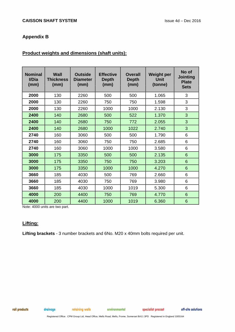
Appendix B Product weights and dimensions (shaft units):
Nominal I/Dia (mm)
Wall Thickness
(mm)
Outside Diameter
(mm)
Effective Depth (mm)
Overall Depth (mm)
Weight per Unit
(tonne)
No of Jointing
Plate Sets
2000 130 2260 500 500 1.065 3
2000 130 2260 750 750 1.598 3
2000 130 2260 1000 1000 2.130 3
2400 140 2680 500 522 1.370 3
2400 140 2680 750 772 2.055 3
2400 140 2680 1000 1022 2.740 3
2740 160 3060 500 500 1.790 6
2740 160 3060 750 750 2.685 6
2740 160 3060 1000 1000 3.580 6
3000 175 3350 500 500 2.135 6
3000 175 3350 750 750 3.203 6
3000 175 3350 1000 1000 4.270 6
3660 185 4030 500 769 2.660 6
3660 185 4030 750 769 3.980 6
3660 185 4030 1000 1019 5.300 6
4000 200 4400 750 769 4.770 6
4000 200 4400 1000 1019 6.360 6
Note: 4000 units are two part.
Lifting: Lifting brackets - 3 number brackets and 6No. M20 x 40mm bolts required per unit.

CAISSON SHAFT SYSTEM Issue 4d – Dec 2016
Registered Office: CPM Group Ltd, Head Office, Mells Road, Mells, Frome, Somerset BA11 3PD Registered in England 1005164
Appendix C
DN2000, DN2750 & DN3000 Joint Sealing
DN3660 & DN4000 Joint Sealing
DN2400 Joint Sealing