Caillebotis AMICO
112
QUALITY PRODUCTS – COAST TO COAST Gratings and Expanded Metals bar grating expanded metal sheets safety grip diamond grip fiberglass grating riveted grating expanded metal grating
-
Upload
mathieu-normandeau -
Category
Documents
-
view
766 -
download
15
Transcript of Caillebotis AMICO

QUALITY PRODUCTS – COAST TO COAST
Gratings and Expanded Metals
bar grating
expanded metal sheets safety grip
diamond grip
fiberglass grating
riveted grating
expanded metal grating

QUALITY PRODUCTS – COAST TO COAST
AMICOAlabama Metal Industries Corporation (AMICO) began in 1939 as a man-ufacturer of metal lath. AMICO has grown to become North America’s leader in the manufacture and distribution of a complete line of industrial gratings and expanded metals. AMICO’s product range also includes metal lath, plaster and drywall beads, concrete forming products and a variety of security barrier product systems. AMICO has manufacturing and distribution facilities throughout North America, with corporate of-fices in Birmingham, AL.
AMICO-ISGEstablished in 1978, ISG is the largest Canadian manufacturer of safety grating products. The 1995 acquisition extended AMICO’s US distribution with a full range of safety gratings, supplementing their existing product range. Within the Canadian market, AMICO-ISG now manufactures/dis-tributes a complete range of AMICO products including expanded metal, bar grating and fiberglass grating coast to coast.
AMICO SEASAFE & IGISeasafe is North America’s most prominent custom fabricator of fiber-glass structural platform and walkway systems. Established in 1979, Seasafe’s manufacturing now has a complete line of molded and pul-truded grating panels, cable tray and a variety of structural shapes. AMI-CO acquired Seasafe in 1998 and a year later added International Grat-ing (IGI) to the organization providing additional manufacturing capacity including production of compression-molded panels, FRP re-bar, and retaining wall as well as 28 years of experience in the fiberglass market.
AMICO DIAMONDDiamond Perforated has grown since 1956 to become one of the larg-est full line manufacturers and distributors of perforated metals in the US. With locations in Visalia CA and Los Angeles CA, Diamond services the market through one of the most advanced perforated manufacturing facilities in North America.
AMICO-KLEMPKlemp’s 75 years of bar grating experience and diverse product range completes AMICO’s product presentation in the North American market. Klemp’s recognized capabilities in the custom grating fabrication mar-ket and proven experience complements AMICO’s manufacturing and distribution network while adding several new locations to service local markets.
ALABAMA METAL INDUSTRIES CORPORATION3245 Fayette Avenue • Birmingham, Alabama 35208
www.amico-online.com
11
Contents◆◆ Expanded Metal and Expanded Metal Grating . . . . . . . . . . . . . . . . . . . . . . .2-12
Regular and Flattened Expanded Metal . . . . . . . . . . . . . . . . . . . . . . . . . . . . . . . . . . . . . . . . . . . .2-6Stainless Steel and Aluminum . . . . . . . . . . . . . . . . . . . . . . . . . . . . . . . . . . . . . . . . . . . . . . .6
Expanded Metal Grating . . . . . . . . . . . . . . . . . . . . . . . . . . . . . . . . . . . . . . . . . . . . . . . . . . . . . . .7-9How To Order . . . . . . . . . . . . . . . . . . . . . . . . . . . . . . . . . . . . . . . . . . . . . . . . . . . . . . . . . .10Standard Pallets . . . . . . . . . . . . . . . . . . . . . . . . . . . . . . . . . . . . . . . . . . . . . . . . . . . . . . . .11Nomenclature . . . . . . . . . . . . . . . . . . . . . . . . . . . . . . . . . . . . . . . . . . . . . . . . . . . . . . . . . .12
◆◆ Bar Grating . . . . . . . . . . . . . . . . . . . . . . . . . . . . . . . . . . . . . . . . . . . . . . . . . .13-70Types of Grating . . . . . . . . . . . . . . . . . . . . . . . . . . . . . . . . . . . . . . . . . . . . . . . . . . . . . . . . . . . . . .13Steel Bar Grating . . . . . . . . . . . . . . . . . . . . . . . . . . . . . . . . . . . . . . . . . . . . . . . . . . . . . . . . . . .14-48Standard Welded / Press Locked . . . . . . . . . . . . . . . . . . . . . . . . . . . . . . . . . . . . . . . . .15-16Close Mesh Welded / Press Locked . . . . . . . . . . . . . . . . . . . . . . . . . . . . . . . . . . . . . .17-21Stainless Steel . . . . . . . . . . . . . . . . . . . . . . . . . . . . . . . . . . . . . . . . . . . . . . . . . . . . . . .22-23Railroad Grating . . . . . . . . . . . . . . . . . . . . . . . . . . . . . . . . . . . . . . . . . . . . . . . . . . . . . . . .24
Heavy Duty Steel Grating . . . . . . . . . . . . . . . . . . . . . . . . . . . . . . . . . . . . . . . . . . . . . . . . . . . .25-35Aluminum Grating . . . . . . . . . . . . . . . . . . . . . . . . . . . . . . . . . . . . . . . . . . . . . . . . . . . . . . . . . .36-49
I-Bar Swage-locked Aluminum . . . . . . . . . . . . . . . . . . . . . . . . . . . . . . . . . . . . . . . . . .37-41Rectangular Bar Swage-locked and Press-locked Aluminum . . . . . . . . . . . . . . . . . . . .42-48Duo-GripTM Extruded Aluminum Grating . . . . . . . . . . . . . . . . . . . . . . . . . . . . . . . . . . . . . . .49
Riveted Grating . . . . . . . . . . . . . . . . . . . . . . . . . . . . . . . . . . . . . . . . . . . . . . . . . . . . . . . . . . . .50-54Steel Riveted Grating . . . . . . . . . . . . . . . . . . . . . . . . . . . . . . . . . . . . . . . . . . . . . . . . . .51-52Aluminum Riveted Grating . . . . . . . . . . . . . . . . . . . . . . . . . . . . . . . . . . . . . . . . . . . . . .53-54
Riv-Dexteel® Bridge Deck Grating . . . . . . . . . . . . . . . . . . . . . . . . . . . . . . . . . . . . . . . . . . . . . .55-56Stair Treads . . . . . . . . . . . . . . . . . . . . . . . . . . . . . . . . . . . . . . . . . . . . . . . . . . . . . . . . . . . . . . .57-63Anchoring Details . . . . . . . . . . . . . . . . . . . . . . . . . . . . . . . . . . . . . . . . . . . . . . . . . . . . . . .64Installation Clearances . . . . . . . . . . . . . . . . . . . . . . . . . . . . . . . . . . . . . . . . . . . . . . . . . . .65Welding Standards . . . . . . . . . . . . . . . . . . . . . . . . . . . . . . . . . . . . . . . . . . . . . . . . . . . . . .66Manufacturing Tolerances . . . . . . . . . . . . . . . . . . . . . . . . . . . . . . . . . . . . . . . . . . . . . . . . .67Glossary . . . . . . . . . . . . . . . . . . . . . . . . . . . . . . . . . . . . . . . . . . . . . . . . . . . . . . . . . . . . . .68Grating Design Data . . . . . . . . . . . . . . . . . . . . . . . . . . . . . . . . . . . . . . . . . . . . . . . . . .69-70
◆◆ Safety Grating . . . . . . . . . . . . . . . . . . . . . . . . . . . . . . . . . . . . . . . . . . . . . . . .71-91Diamond-Grip® . . . . . . . . . . . . . . . . . . . . . . . . . . . . . . . . . . . . . . . . . . . . . . . . . . . . . . . . . . . . .71-74Diamond-Grip® Walkway . . . . . . . . . . . . . . . . . . . . . . . . . . . . . . . . . . . . . . . . . . . . . . . . . . . . .75-76Safety-Grip® . . . . . . . . . . . . . . . . . . . . . . . . . . . . . . . . . . . . . . . . . . . . . . . . . . . . . . . . . . . . . .77-80Safety-Grip® Walkway . . . . . . . . . . . . . . . . . . . . . . . . . . . . . . . . . . . . . . . . . . . . . . . . . . . . . . .81-82Safety-Tread® Channel . . . . . . . . . . . . . . . . . . . . . . . . . . . . . . . . . . . . . . . . . . . . . . . . . . . . . . .83-84Safety-Tread® Flooring . . . . . . . . . . . . . . . . . . . . . . . . . . . . . . . . . . . . . . . . . . . . . . . . . . . . . . .85-86Safety-Tread® Ladder Rungs . . . . . . . . . . . . . . . . . . . . . . . . . . . . . . . . . . . . . . . . . . . . . . . . . .87-88Stair Treads . . . . . . . . . . . . . . . . . . . . . . . . . . . . . . . . . . . . . . . . . . . . . . . . . . . . . . . . . . . . . . . . .89Installation Accessories . . . . . . . . . . . . . . . . . . . . . . . . . . . . . . . . . . . . . . . . . . . . . . . . . .90Slip Resistant Values . . . . . . . . . . . . . . . . . . . . . . . . . . . . . . . . . . . . . . . . . . . . . . . . . . . .91
◆◆ Fiberglass Grating . . . . . . . . . . . . . . . . . . . . . . . . . . . . . . . . . . . . . . . . . . . .92-104GatorGrate® Open Molded Grating . . . . . . . . . . . . . . . . . . . . . . . . . . . . . . . . . . . . . . . . . . . . . .92-93KorDek® Compression Molded . . . . . . . . . . . . . . . . . . . . . . . . . . . . . . . . . . . . . . . . . . . . . . . . .94-95GatorPlateTM . . . . . . . . . . . . . . . . . . . . . . . . . . . . . . . . . . . . . . . . . . . . . . . . . . . . . . . . . . . . . . . . .96GatorGrate® Stair Tread . . . . . . . . . . . . . . . . . . . . . . . . . . . . . . . . . . . . . . . . . . . . . . . . . . . . . . . . .97KorPlateTM and KorDek® Stair Treads . . . . . . . . . . . . . . . . . . . . . . . . . . . . . . . . . . . . . . . . . . . . . . .98GatorDeck® Pultruded Grating . . . . . . . . . . . . . . . . . . . . . . . . . . . . . . . . . . . . . . . . . . . . . . . .99-101Fiberglass Sheet Pile and Louvers . . . . . . . . . . . . . . . . . . . . . . . . . . . . . . . . . . . . . . . . . . . . . . .102Fiberglass Cable Tray Systems . . . . . . . . . . . . . . . . . . . . . . . . . . . . . . . . . . . . . . . . . . . . . . . . . .103Fiberglass Fabrication Services . . . . . . . . . . . . . . . . . . . . . . . . . . . . . . . . . . . . . . . . . . . . . . . . .104Creative Solutions . . . . . . . . . . . . . . . . . . . . . . . . . . . . . . . . . . . . . . . . . . . . . . . . . . . . . . . .105-106
◆◆ Perforated Metal . . . . . . . . . . . . . . . . . . . . . . . . . . . . . . . . . . . . . . . . . . . . . . .107
Visit our website at: www.amico-grating.com
Expanded Metal
Expanded Metal Grating
Welded Bar Grating
Press Locked Bar Grating
Fiberglass Grating
Safety Grating
Expanded Metal
2
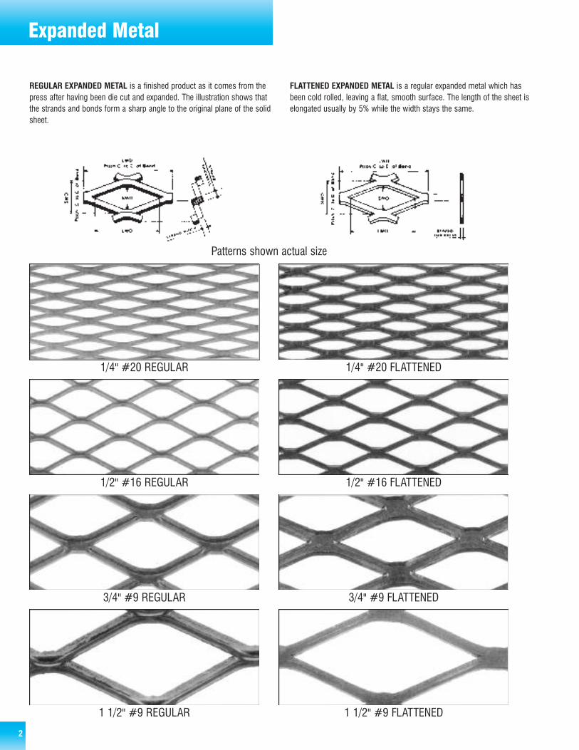
REGULAR EXPANDED METAL is a finished product as it comes from thepress after having been die cut and expanded. The illustration shows thatthe strands and bonds form a sharp angle to the original plane of the solidsheet.
FLATTENED EXPANDED METAL is a regular expanded metal which hasbeen cold rolled, leaving a flat, smooth surface. The length of the sheet iselongated usually by 5% while the width stays the same.
1 1/2" #9 REGULAR 1 1/2" #9 FLATTENED
3/4" #9 REGULAR 3/4" #9 FLATTENED
1/2" #16 REGULAR 1/2" #16 FLATTENED
1/4" #20 REGULAR 1/4" #20 FLATTENED
Patterns shown actual size
Expanded Metal
3
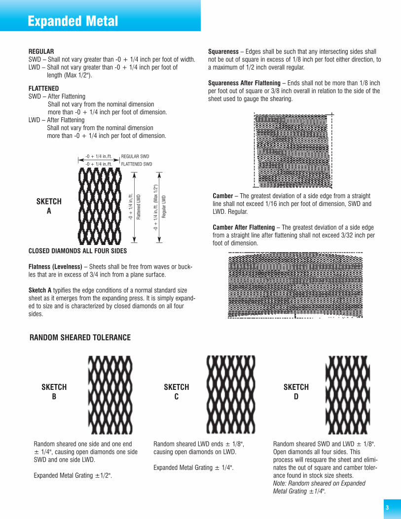
REGULARSWD – Shall not vary greater than -0 + 1/4 inch per foot of width.LWD – Shall not vary greater than -0 + 1/4 inch per foot of
length (Max 1/2").
FLATTENEDSWD – After Flattening
Shall not vary from the nominal dimension more than -0 + 1/4 inch per foot of dimension.
LWD – After FlatteningShall not vary from the nominal dimension more than -0 + 1/4 inch per foot of dimension.
CLOSED DIAMONDS ALL FOUR SIDES
Flatness (Levelness) – Sheets shall be free from waves or buck-les that are in excess of 3/4 inch from a plane surface.
Sketch A typifies the edge conditions of a normal standard sizesheet as it emerges from the expanding press. It is simply expand-ed to size and is characterized by closed diamonds on all foursides.
Camber – The greatest deviation of a side edge from a straightline shall not exceed 1/16 inch per foot of dimension, SWD andLWD. Regular.
Camber After Flattening – The greatest deviation of a side edgefrom a straight line after flattening shall not exceed 3/32 inch perfoot of dimension.
Squareness – Edges shall be such that any intersecting sides shallnot be out of square in excess of 1/8 inch per foot either direction, toa maximum of 1/2 inch overall regular.
Squareness After Flattening – Ends shall not be more than 1/8 inchper foot out of square or 3/8 inch overall in relation to the side of thesheet used to gauge the shearing.
Random sheared one side and one end± 1/4", causing open diamonds one sideSWD and one side LWD.
Expanded Metal Grating ±1/2".
Random sheared LWD ends ± 1/8",causing open diamonds on LWD.
Expanded Metal Grating ± 1/4".
Random sheared SWD and LWD ± 1/8".Open diamonds all four sides. Thisprocess will resquare the sheet and elimi-nates the out of square and camber toler-ance found in stock size sheets. Note: Random sheared on ExpandedMetal Grating ±1/4".
SKETCHB
SKETCHA
SKETCHC
SKETCHD
-0 + 1/4 in./ft.
-0 + 1/4 in./ft.
REGULAR SWD
Regular LWD
FLATTENED SWD
Flattened LW
D
-0 + 1/4 in./ft.
-0 + 1/4in./ft. (Max1/2")
RANDOM SHEARED TOLERANCE

Regular Expanded Metal
4
CARBON STEEL - ASTM A 1011
StyleWeight inlbs. perC.S.F
StandardSizes inFeet
Size ofOpenings ininches
Center toCenter ofBond in inches
Size ofStrands ininches
Percent Open Area
No. ofDiamonds per ft. SWD
OverallThickness in inches
Plain Galv. Width Length Width Length Width Length Width Thickness
3/16" #22 62 A B B 0.166 0.437 0.200 0.500 0.050 0.030 60 60 0.086
3/16" #20 75 A B B 0.166 0.437 0.200 0.500 0.050 0.036 57 60 0.090
1/4" #20 86 129 4-8 8-4 0.172 0.719 0.255 1.000 0.073 0.036 45 47 0.125
1/4" #18 114 171 4-8 8-4 0.172 0.719 0.255 1.000 0.073 0.048 43 47 0.125
5/16" #18 104 - 4-8 8-4 0.188 0.688 0.333 1.000 0.094 0.048 60 36 0.170
1/2" #20 43 59 4-8 8-4 0.438 0.938 0.500 1.200 0.072 0.036 80 24 0.124
1/2" #18 70 85 4-6-8 8-10-4 0.438 0.938 0.500 1.200 0.088 0.048 77 24 0.155
1/2" #16 86 97 4-6-8 8-10-4 0.375 0.938 0.500 1.200 0.086 0.060 71 24 0.157
1/2" #13 147 173 4-6-8 8-10-4 0.313 0.938 0.500 1.200 0.096 0.092 58 24 0.182
1/2" #13 282 310 8 4 0.250 0.800 0.500 1.200 0.188 0.092 25 24 0.275
3/4" #16 54 65 4-6-8 8-10-4 0.813 1.750 0.923 2.000 0.099 0.060 85 13 0.186
3/4" #13 80 92 4-6-8 8-10-4 0.750 1.688 0.923 2.000 0.096 0.092 78 13 0.195
3/4" #10 120 136 4-6-8 8-10-4 0.750 1.625 0.923 2.000 0.144 0.092 77 13 0.282
3/4" #9 180 195 4-6-8 8-10-12 0.688 1.563 0.923 2.000 0.148 0.134 68 13 0.300
1" #16 44 51 4-8 8-4 1.000 2.063 1.090 2.400 0.096 0.060 86 11 0.182
1" #14 76 82 4-8 8-4 0.875 1.563 1.090 2.400 0.122 0.075 75 11 0.225
1" #12 101 108 4-8 8-4 0.907 1.563 1.090 2.400 0.109 0.105 78 11 0.225
1" #10 170 187 4-8 8-4 0.750 1.563 1.090 2.400 0.155 0.135 62 11 0.375
1" #10H 200 221 4-8 8-4 0.725 1.563 1.090 2.400 0.180 0.135 60 11 0.390
1" #7 412 453 8 4 0.576 1.563 1.090 2.400 0.275 0.183 45 11 0.550
1 1/2" #18 20 25 4-8 8-4 1.313 2.625 1.330 3.000 0.067 0.048 93 9 0.140
1 1/2" #16 40 48 4-8 8-10-12-4 1.250 2.625 1.330 3.000 0.107 0.060 89 9 0.211
1 1/2" #14 44 50 4-8 8-4 1.188 2.625 1.330 3.000 0.097 0.075 85 9 0.242
1 1/2" #13 60 68 4-6-8 8-10-12-4 1.188 2.500 1.330 3.000 0.104 0.092 86 9 0.215
1 1/2" #12 72 85 4-8 8-4 1.112 2.375 1.330 3.000 0.109 0.105 85 9 0.225
1 1/2" #10 79 89 4-6-8 8-10-4 1.188 2.500 1.330 3.000 0.137 0.092 85 9 0.289
1 1/2" #10 170 187 4-8 8-4 1.000 2.375 1.330 3.000 0.200 0.135 74 9 0.350
1 1/2" #10H 200 220 4-8 8-4 0.830 2.375 1.330 3.000 0.240 0.135 72 9 0.460
1 1/2" #9 120 131 4-6-8 8-10-12-4 1.125 2.375 1.330 3.000 0.142 0.135 75 9 0.295
1 1/2" #6 250 273 4-6-8 8-10-12-4 1.000 2.313 1.330 3.000 0.201 0.198 69 9 0.425
2" #10 68 75 B B 1.625 3.438 1.850 4.000 0.164 0.092 86 6.5 0.312
2" #9 90 102 B B 1.563 3.375 1.850 4.000 0.149 0.134 86 6.5 0.325
Above conforms to EMMA 557-99
A. Not AvailableB. Special Order only

Flattened Expanded Metal
5
CARBON STEEL - ASTM A 1011
StyleWeight inlbs. perC.S.F
StandardSizes inFeet
Size ofOpenings ininches
Center toCenter ofBond in inches
Size ofStrands ininches
Percent Open Area
No. ofDiamonds per ft. SWD
OverallThickness in inches
Plain Galv. Width Length Width Length Width Length Width Thickness
3/16" #22 60 A B B 0.085 0.459 0.200 0.520 0.057 0.024 40 60 0.024
3/16" #20 72 A B B 0.085 0.459 0.200 0.520 0.057 0.029 39 60 0.029
1/4" #20 83 124 4-8 8-4 0.094 0.688 0.255 1.030 0.086 0.030 47 47 0.030
1/4" #18 111 165 4-8 8-4 0.094 0.688 0.255 1.030 0.086 0.040 40 47 0.040
5/16" #18 95 - 4-8 8-4 0.172 0.813 0.333 1.030 0.099 0.040 45 36 0.040
1/2" #20 40 51 4-8 8-4 0.375 1.000 0.500 1.260 0.070 0.029 72 24 0.029
1/2" #18 66 88 3-4-6-8 8-10-4 0.281 1.000 0.500 1.260 0.109 0.039 69 24 0.039
1/2" #16 82 100 3-4-6-8 8-10-4 0.250 1.000 0.500 1.260 0.103 0.050 60 24 0.050
1/2" #13 140 162 3-4-6-8 8-10-4 0.250 1.000 0.500 1.260 0.122 0.070 57 24 0.070
3/4" #16 51 61 3-4-6-8 8-10-4 0.750 1.750 0.923 2.100 0.115 0.048 75 13 0.048
3/4" #14 63 75 3-4-6-8 8-10-4 0.688 1.813 0.923 2.100 0.119 0.061 70 13 0.061
3/4" #13 75 86 3-4-6-8 8-10-4 0.688 1.782 0.923 2.100 0.119 0.070 73 13 0.070
3/4" #10 114 125 4-8 8-4 0.637 1.755 0.923 2.100 0.160 0.070 68 13 0.070
3/4" #9 171 186 3-4-6-8 8-10-12-4 0.563 1.688 0.923 2.100 0.164 0.120 63 13 0.120
1" #16 41 50 4-8 8-4 0.875 2.250 1.090 2.560 0.115 0.048 77 11 0.048
1" #14 73 77 4-8 8-4 0.790 2.000 1.090 2.560 0.125 0.070 80 11 0.070
1" #12 96 110 4-8 8-4 0.785 2.000 1.090 2.560 0.156 0.085 74 11 0.085
1" #10 165 179 4-8 8-4 0.750 1.900 1.090 2.560 0.160 0.110 58 11 0.110
1 1/2" #16 38 44 4-8 8-4 1.063 2.750 1.330 3.200 0.123 0.048 82 9 0.048
1 1/2" #14 46 56 3-4-6-8 8-4 1.063 2.750 1.330 3.200 0.138 0.060 82 9 0.060
1 1/2" #13 57 68 3-4-6-8 8-4 1.063 2.750 1.330 3.200 0.138 0.070 80 9 0.070
1 1/2" #12 66 76 4-8 8-4 1.296 2.625 1.330 3.200 0.116 0.085 83 9 0.085
1 1/2" #10 165 179 4-8 8-4 0.900 2.560 1.330 3.200 0.188 0.110 63 9 0.110
1 1/2 “ #9 111 128 3-4-6-8 8-10-12-4 1.000 2.563 1.330 3.200 0.175 0.110 77 9 0.110
1 1/2 “ #6 241 260 3-4 8-10 1.000 2.563 1.33 3.20 0.255 0.173 65 9 0.172
Above conforms to EMMA 557-99
A. Not AvailableB. Special Order only

3/16" .032 23 B B 0.166 0.437 0.200 0.500 0.050 0.032 52 60 0.0681/2" .051 27 4 8 0.375 0.938 0.500 1.200 0.094 0.051 70 24 0.1581/2" .081 44 4 8 0.375 0.938 0.500 1.200 0.096 0.081 60 24 0.1863/4" .051 17 4 8 0.813 1.175 0.923 2.000 0.109 0.051 90 13 0.2003/4" .064 22 4-8 8-4 0.823 1.660 0.923 2.000 0.111 0.064 75 13 0.2003/4" .081 41 4 8 0.750 1.688 0.923 2.000 0.166 0.081 74 13 0.3003/4" .081L 27 4-8 8-4 0.750 1.680 0.923 2.000 0.110 0.081 76 13 0.2003/4" .081H 41 4-8 8-4 0.750 1.688 0.923 2.000 0.165 0.081 69 13 0.3003/4" .125 65 4 8 0.688 1.688 0.923 2.000 0.170 0.125 66 13 0.3053/4" .188 113 4-8 8-4 0.590 1.350 0.923 2.000 0.200 0.188 60 13 0.400
1 1/2" .051 13 4-8 8-4 1.225 2.400 1.330 3.000 0.110 0.051 88 9 0.2001 1/2" .081 22 4 8 1.188 2.500 1.333 3.000 0.128 0.081 87 9 0.2401 1/2" .125 43 4 8 1.188 2.500 1.333 3.000 0.163 0.125 78 9 0.300
A. Not Available Above conforms to EMMA 557-99B. Special Order Only
ALUMINUM REGULAR-ALLOY 3003 H14 (AVAILABLE IN 5005 H34)
3/16" .032 25 8 4 0.078 0.313 0.218 0.438 0.060 0.029 43 60 0.0281/2" .051 25 4 8 0.313 1.000 0.500 1.270 0.091 0.040 57 24 0.0401/2" .081 41 4 8 0.313 1.000 0.500 1.270 0.103 0.060 57 24 0.0603/4" .051 16 4 8 0.750 1.813 0.923 2.120 0.114 0.040 73 13 0.0403/4" .064 20 4-8 8-4 0.750 1.780 0.923 2.130 0.122 0.051 72 13 0.0513/4" .081L 25 4-8 8-4 0.687 1.750 0.923 2.215 0.134 0.070 70 13 0.0703/4" .081H 38 4-8 8-4 0.688 1.750 0.923 2.120 0.172 0.070 63 13 0.0703/4" .125 61 4 8 0.625 1.750 0.923 2.120 0.180 0.095 55 13 0.0953/4" .188 107 4-8 8-4 0.484 1.593 0.923 2.130 0.205 0.170 60 13 0.170
1 1/2" .051 11 4-8 8-4 1.095 2.750 1.330 3.090 0.120 0.040 80 9 0.0401 1/2" .081 20 4 8 1.063 2.750 1.333 3.150 0.144 0.055 75 9 0.0551 1/2" .125 40 4 8 1.000 2.750 1.333 3.150 0.190 0.080 65 9 0.080
ALUMINUM FLATTENED-ALLOY 3003 H14 (AVAILABLE IN 5005 H34)
Stainless Steel & Aluminum
6
StyleWeight inlbs. perC.S.F
StandardSizes inFeet
Size ofOpenings ininches
Center toCenter ofBond in inches
Size ofStrands ininches
Percent Open Area
No. ofDiamonds per ft. SWD
OverallThickness in inches
1/2" #20 50 4 8 0.437 0.937 0.500 1.200 0.080 0.037 70 24 0.1641/2" #18 73 4 8 0.438 0.938 0.500 1.200 0.087 0.050 77 24 0.1641/2" #16 91 4 8 0.438 0.938 0.500 1.200 0.087 0.062 70 24 0.1641/2" #13 187 4 8 0.313 0.875 0.500 1.200 0.120 0.093 58 24 0.2253/4" #18 48 4 8 0.813 1.750 0.923 2.000 0.106 0.050 89 13 0.2003/4" #16 60 4 8 0.813 1.750 0.923 2.000 0.106 0.062 85 13 0.2003/4" #13 91 4 8 0.750 1.688 0.923 2.000 0.108 0.093 78 13 0.2003/4" #9 205 4 8 0.688 1.563 0.923 2.000 0.161 0.140 67 13 0.300
1 1/2" #16 45 4 8 1.250 2.750 1.333 3.000 0.115 0.062 89 9 0.2201 1/2" #13 68 4 8 1.250 2.625 1.333 3.000 0.116 0.093 86 9 0.2201 1/2" #9 137 4 8 1.125 2.500 1.333 3.000 0.155 0.140 75 9 0.280Above conforms to EMMA 557-99
1/2" #20 48 4 8 0.312 1.000 0.500 1.260 0.091 0.033 60 24 0.0331/2" #18 69 4 8 0.313 1.000 0.500 1.260 0.093 0.040 68 24 0.0401/2" #16 86 4 8 0.313 1.000 0.500 1.260 0.093 0.050 60 24 0.0501/2" #13 178 4 8 0.250 1.000 0.500 1.260 0.132 0.080 56 24 0.0803/4" #18 46 4 8 0.750 1.813 0.923 2.100 0.118 0.040 77 13 0.0403/4" #16 57 4 8 0.750 1.813 0.923 2.100 0.118 0.050 75 13 0.0503/4" #13 87 4 8 0.625 1.750 0.923 2.100 0.120 0.070 74 13 0.0703/4" #9 195 4 8 0.563 1.688 0.923 2.100 0.160 0.119 64 13 0.119
1 1/2" #16 43 4 8 1.063 2.750 1.330 3.150 0.124 0.050 83 9 0.0501 1/2" #13 65 4 8 1.000 2.625 1.330 3.150 0.124 0.079 79 9 0.0791 1/2" #9 131 4 8 0.938 2.625 1.330 3.150 0.165 0.119 76 9 0.119Above conforms to EMMA 557-99
STAINLESS STEEL REGULAR-TYPE 304 (AVAILABLE IN T-304L, T-316, T-316L)
STAINLESS STEEL FLATTENED-TYPE 304 (AVAILABLE IN T-304L, T-316, T-316L)
Above conforms to EMMA 557-99

Expanded Metal Grating
7
Ornamesh Carbon Steel - ASTM A 569/569M - Aluminum Alloy 5005 H34
Aluminum Long Length SWD (Catwalk Grating) - ALLOY 5052 H32
Above conforms to EMMA 557-99
661B
661B
Carbon Steel Long Length SWD (Catwalk Grating) - ASTM A 569/569M
Aluminum Grating - ALLOY 5052 H32
Above conforms to EMMA 557-99
Carbon Steel Grating - ASTM A 569/569MSize of
Strands
in Inches
Center to Center
of Bonds
in Inches
Percent
Open
Area
No. of
Diamonds
Per Ft. SWD
Overall
Thickness
in Inches
Size
of Openings
in Inches
Standard
Sizes
in Feet
Weight in Lbs.
Per c.s.f.
Style
Plain Galv. Width Length Width Length Width Length Width Thickness
2 lb. 200 218 4-6 8 1.000 3.600 1.333 5.330 0.235 0.135 77 9 0.460
3 lb. 300 320 4-6 8-10 0.938 3.438 1.333 5.330 0.261 0.183 73 9 0.500
3.14 lb 314 334 4-6 8-10 1.625 4.875 2.000 6.000 0.308 0.250 74 6 0.562
4 lb 400 430 4-5-6 8-10 0.938 3.438 1.333 5.330 0.297 0.215 65 9 0.625
4.27 lb 427 457 4-6 8-10 1.000 2.875 1.412 4.000 0.297 0.250 58 8.5 0.625
5 lb 500 550 4-5-6 8-10 0.813 3.375 1.333 5.330 0.327 0.250 52 9 0.625
6.25 lb 625 685 4-6 8-10 0.813 3.375 1.412 5.330 0.347 0.312 55 8.5 0.750
7 lb 700 750 4-6 8 0.813 3.375 1.412 5.330 0.338 0.312 60 8.5 0.750
2 lb 200 4-6 8 1.000 3.600 1.333 5.330 0.235 0.250 77 9 0.460
2 lb 200 218 8 4 1.000 3.600 1.333 5.330 0.235 0.135 77 9 0.460
3 lb 300 320 8-10 2-2.6-3-4 0.938 3.438 1.333 5.330 0.261 0.183 73 9 0.500
3.14 lb 314 334 8-10 2-2.6-3-4 1.625 4.875 2.000 6.000 0.308 0.250 74 8.5 0.562
4 lb 400 430 8-10 2-2.6-3-4 0.938 3.438 1.330 5.330 0.297 0.215 65 9 0.625
4.27 lb 427 457 8-10 2-2.6-3-4 1.000 2.875 1.412 4.000 0.297 0.250 58 9 0.625
5 lb 500 550 8-10 2-2.6-3-4 0.813 3.375 1.333 5.330 0.327 0.250 52 9 0.625
6.25 lb 625 685 8 4 0.813 3.375 1.412 5.330 0.347 0.312 55 8.5 0.750
2 lb 200 8 2-2.6-3 1.000 3.600 1.333 5.330 0.235 0.250 77 9 0.460
Size ofStrands
in Inches
Center to Centerof Bondsin Inches
PercentOpenArea
Sizeof Openings
in Inches
StandardSizes
in FeetWeight in Lbs.
Per c.s.f.Style
Plain. Width Length Width Length Width Length Width Thickness
Steel 1.590 4-6 8 1.327 6.400 1.550 7.100 0.122 0.131 65
Aluminum 0.630 4-6 8 1.250 6.125 1.500 5.330 0.125 0.134 65
2.0 lb-3.0 lb-4.0 lb-5.0 lb-6.25 lb-7.0 lb 3.14 lb 4.27 lb
StyleWeight inlbs. perC.S.F
StandardSizes inFeet
Size ofOpenings ininches
Center toCenter ofBond in inches
Size ofStrands ininches
Percent Open Area
No. ofDiamonds per ft. SWD
OverallThickness in inches
Plain Galv. Width Length Width Length Width Length Width Thickness2 lb 200 218 4-6 8 1.000 3.600 1.333 5.330 0.235 0.135 77 9 0.4603 lb 300 320 4-6 8-10 0.938 3.438 1.333 5.330 0.261 0.183 73 9 0.500
3.14 lb 314 334 4-6 8-10 1.625 4.875 2.000 6.000 0.308 0.250 74 6 0.5624 lb 400 430 4-5-6 8-10 0.938 3.438 1.333 5.330 0.297 0.215 65 9 0.625
4.27 lb 427 457 4-6 8-10 1.000 2.875 1.412 4.000 0.297 0.250 58 8.5 0.6255 lb 500 550 4-5-6 8-10 0.813 3.375 1.333 5.330 0.327 0.250 52 9 0.625
6.25 lb 625 685 4-6 8-10 0.813 3.375 1.412 5.330 0.347 0.312 55 8.5 0.7507 lb 700 750 4-6 8 0.813 3.375 1.412 5.330 0.388 0.312 60 8.5 0.750
Above conforms to EMMA 557-99
CARBON STEEL GRATING-ASTM A1011
StyleWeight inlbs. per Sq. Ft.
StandardSizes inFeet
Size ofOpenings ininches
Center toCenter ofBond in inches
Size ofStrands ininches
Percent Open Area
2 lb 200 218 8 4 1.000 3.600 1.333 5.330 0.235 0.135 77 9 0.4603 lb 300 320 8-10 2-2.6-3-4 0.938 3.438 1.333 5.330 0.261 0.183 73 9 0.500
3.14 lb 314 334 8-10 2-2.6-3-4 1.625 4.875 2.000 6.000 0.308 0.250 74 6 0.5624 lb 400 430 8-10 2-2.6-3-4 0.938 3.438 1.330 5.330 0.297 0.215 65 9 0.625
4.27 lb 427 457 8-10 2-2.6-3-4 1.000 2.875 1.412 4.000 0.297 0.250 58 8.5 0.6255 lb 500 550 8-10 2-2.6-3-4 0.813 3.375 1.333 5.330 0.327 0.250 52 9 0.625
6.25 lb 625 685 8 4 0.813 3.375 1.412 5.330 0.347 0.312 55 8.5 0.750Above conforms to EMMA 557-99
CARBON STEEL LONG LENGTH SWD (CATWALK GRATING)-ASTM A 569/569M
2 lb 200 - 4-6 8 1.000 3.600 1.333 5.330 0.235 0.250 77 9 0.460Above conforms to EMMA 557-99
ALUMINUM GRATING-ALLOY 5052 H32
2 lb 200 - 8 2-2.6-3-4 1.000 3.600 1.333 5.330 0.235 0.250 77 9 0.460Above conforms to EMMA 557-99
ALUMINUM LONG LENGTH SWD (CATWALK GRATING)-ALLOY 5052 H32
Plain Width Length Width Length Width Length Width ThicknessSteel 1.590 4-6 8 1.327 6.400 1.550 7.100 0.122 0.131 65Aluminum 0.630 4-6 8 1.250 6.125 1.500 5.330 0.125 0.134 65
Above conforms to EMMA 557-99
ORNAMESH CARBON STEEL-ASTM A A1011-ALUMINUM ALLOY 5005 H34

Expanded Metal Grating
8
GratinegeStylee 50e 100e 150e 200e 250e 300e 350e 400e 450e 500e
2.0#eCARBON STEELe
3.0#eCARBON STEELe
3.14#eCARBON STEELe
4.0#eCARBON STEELe
4.27#eCARBON STEELe
5.0#eCARBON STEELe
Loead in ePoeunds_____________________________________________________________ Deflection in Inchese
Clea
reSp
ane
Leoad
eCo
nd.e
ce
ue
ce
ue
ce
ue
ce
ue
ce
ue
ce
ue
Deflections shown in shaded areas can be safely used at the discretion of the engineer: however, these deflections exceed 1⁄4".
18" .052 .105 .158 .211 .264 .317 36724" .125 .250 .175 .50030" .244 .48936" .42218" .049 .099 .147 .196 .245 .294 .34324" .156 .313 .46830" .38236" .79124" .068 .132 .197 .263 .329 .395 .46230" .116 .228 .345 .46036" .192 .380 .57042" .280 .56148" .380 .76224" .073 .146 .220 .293 .366 .44030" .155 .311 .46336" .330 .66042" .52724" .049 .094 .140 .187 .234 .280 .326 .372 .420 .46530" .099 .198 .297 .39536" .180 .357 .53542" .225 .455 .68448" .342 .68724" .057 .115 .173 .230 .288 .346 .404 .46230" .129 .259 .388 .51736" .315 .62642" .44948" .74524" .031 .064 .096 .128 .160 .192 .224 .256 .288 .32030" .060 .120 .180 .240 .300 .360 .420 .48036". 101 .205 .310 .402 .505 .60542" .158 .315 .473 .63048" .218 .433 .64824" .037 .073 .111 .147 .184 .222 .259 .296 .333 .37030" .068 .135 .205 .274 .340 .410 .477 .54536" .180 .358 .53642" .283 .56548" .48724" .038 .078 .116 .156 .196 .235 .275 .315 .355 .39530" .081 .163 .245 .327 .409 .49136" .124 .250 .379 .50542" .199 .399 .59848" .242 .480 .72024" .038 .079 .120 .160 .200 .240 .280 .320 .360 .40030" .078 .156 .235 .312 .390 .47036" .186 .373 .56042" .37948" .54224" .023 .047 .070 .093 .116 .140. 164 .186 .210 .23430" .033 .087 .130 .174 .217 .261 .304 .348. 391 .43336" .078 .154 .230 .305 .383 .458 .53542" .103 .206 .310 .414 .515 .61748" .155 .306 .459 .61054" .242 .485 .73024" .025 .050 .075 .100 .125 .150 .175 .200 .225 .25030" .061 .123 .184 .246 .307 .369 .430 .491 .55236" .133 .265 .395 .52642" .200 .400 .60048" .355 .70854" .605
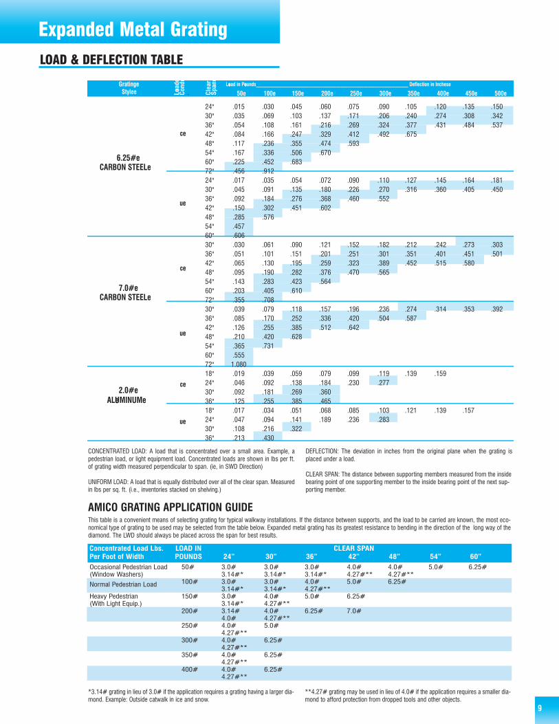
LOAD & DEFLECTION TABLE
Expanded Metal Grating
9
This table is a convenient means of selecting grating for typical walkway installations. If the distance between supports, and the load to be carried are known, the most eco-nomical type of grating to be used may be selected from the table below. Expanded metal grating has its greatest resistance to bending in the direction of the long way of thediamond. The LWD should always be placed across the span for best results.
*3.14# grating in lieu of 3.0# if the application requires a grating having a larger dia-mond. Example: Outside catwalk in ice and snow.
**4.27# grating may be used in lieu of 4.0# if the application requires a smaller dia-mond to afford protection from dropped tools and other objects.
AMICO GRATING APPLICATION GUIDE
50e 100e 150e 200e 250e 300e 350e 400e 450e 500eGratinge
Stylee
6.25#eCARBON STEELe
7.0#eCARBON STEELe
2.0#eALeUMINUMe
Leoad in Peounds_____________________________________________________________ Deflection in Inchese
ce
ue
Clea
reSp
ane
Leoad
eCo
nde
.
ce
ue
ce
ue
24" .015 .030 .045 .060 .075 .090 .105 .120 .135 .15030" .035 .069 .103 .137 .171 .206 .240 .274 .308 .34236" .054 .108 .161 .216 .269 .324 .377 .431 .484 .53742" .084 .166 .247 .329 .412 .492 .67548" .117 .236 .355 .474 .59354" .167 .336 .506 .67060" .225 .452 .68372" .456 .91224" .017 .035 .054 .072 .090 .110 .127 .145 .164 .18130" .045 .091 .135 .180 .226 .270 .316 .360 .405 .45036" .092 .184 .276 .368 .460 .55242" .150 .302 .451 .60248" .285 .57654" .45760" .60630" .030 .061 .090 .121 .152 .182 .212 .242 .273 .30336" .051 .101 .151 .201 .251 .301 .351 .401 .451 .50142" .065 .130 .195 .259 .323 .389 .452 .515 .58048" .095 .190 .282 .376 .470 .56554" .143 .283 .423 .56460" .203 .405 .61072" .355 .70830" .039 .079 .118 .157 .196 .236 .274 .314 .353 .39236" .085 .170 .252 .336 .420 .504 .58742" .126 .255 .385 .512 .64248" .210 .420 .62854" .365 .73160" .55572" 1.08018" .019 .039 .059 .079 .099 .119 .139 .15924" .046 .092 .138 .184 .230 .27730" .092 .181 .269 .36036" .125 .255 .385 .46518" .017 .034 .051 .068 .085 .103 .121 .139 .15724" .047 .094 .141 .189 .236 .28330" .108 .216 .32236" .213 .430
CONCENTRATED LOAD: A load that is concentrated over a small area. Example, apedestrian load, or light equipment load. Concentrated loads are shown in lbs per ft.of grating width measured perpendicular to span. (ie, in SWD Direction)
UNIFORM LOAD: A load that is equally distributed over all of the clear span. Measuredin lbs per sq. ft. (i.e., inventories stacked on shelving.)
DEFLECTION: The deviation in inches from the original plane when the grating isplaced under a load.
CLEAR SPAN: The distance between supporting members measured from the insidebearing point of one supporting member to the inside bearing point of the next sup-porting member.
LOAD & DEFLECTION TABLE
Concentrated Load Lbs. LOAD IN CLEAR SPANPer Foot of Width POUNDS 24” 30” 36” 42” 48” 54” 60”Occasional Pedestrian Load 50# 3.0# 3.0# 3.0# 4.0# 4.0# 5.0# 6.25#(Window Washers) 3.14#* 3.14#* 3.14#* 4.27#** 4.27#**
Normal Pedestrian Load 100# 3.0# 3.0# 4.0# 5.0# 6.25#3.14#* 3.14#* 4.27#**
Heavy Pedestrian 150# 3.0# 4.0# 5.0# 6.25#(With Light Equip.) 3.14#* 4.27#**
200# 3.14# 4.0# 6.25# 7.0#4.0# 4.27#**
250# 4.0# 5.0#4.27#**
300# 4.0# 6.25#4.27#**
350# 4.0# 6.25#4.27#**
400# 4.0# 6.25#4.27#**

Expanded Metal & Expanded Metal Grating
10
• Specify the size sheet required, listing SWD first. • Example: 4'-0 SWD x 8'-0 LWD
• Specify the number of sheets or pieces required.
• Specify the nominal width of the diamond SWD • Example: 3/16", 1/4", 1/2", 3/4", 1", 1 1/2", 2"
• Specify the style of the sheet• Example: #18, #20, #16, #13, #9
• Specify R (Regular), F (Flattened)
• Specify the type of metal required• Example: Carbon steel, Stainless steel, Aluminum, etc.
EXAMPLE OF TYPICAL ORDER:100 SHEETS...3/4"...#9F4'-0 X 8'-0 CARBON STEEL
• Specify the size sheet required, listing SWD first.Example: Expanded Metal Grating 4'-0 x 8'-0, 4'-0 x 10'-0, 6'-0 x 5'-0, 6'-0 x 10'-0.
• Specify the number of sheets or pieces required.
• Specify Wt./Sq. Ft. requiredExample: 2.0 lb., 3.0 lb., 3.14 lb., 4.0 lb., 4.27 lb., 5.0 lb., 6.25 lb., 7.0 lb.
EXAMPLE TYPICAL ORDEREXPANDED METAL LONG LENGTH GRATING10'-0 x 2'-0 - 10'-0 X 2'-6 - 10'-0 X 3'-0
4'-0 SWD
8'-0 LWD
8'-0 LWD
EXPANDED METAL GRATING
LONG LENGTH EXPANDED METAL GRATING
2'-0 LWD
SPAN
4'-0 SWD
10'-0 SWD
HOW TO ORDER EXPANDED METAL
HOW TO ORDER EXPANDED METAL GRATING OR LONG LENGTH GRATING
11
Expanded Metal & Expanded Metal Grating
6 x 8
MESH SIZE 4 x 10 SIZE
1/4" # 20 R&F 4 x 8
1/4" # 18 R&F 4 x 8 6 x 8
4 x 10
1/2" # 20 R&F 4 x 8 6 x 10 6 x 10
1/2" # 18 R&F 4 x 8 6 x 10
1/2" # 16 R&F 4 x 8 6 x 8 6 x 8
1/2" # 16 R&F 6 x 8 4 x 10 6 x 10
1/2" # 16 R&F 4 x 10 6 x 10 6 x 8
4 x 8 6 x 10
3/4" # 16 R&F 4 x 8 6 x 8 6 x 8
3/4" # 16 R&F 4 x 10 4 x 10 6 x 10
3/4" # 16 R&F 6 x 8 6 x 10 6 x 8
3/4" # 14 F 4 x 8 4 x 10
3/4" # 13 R&F 4 x 8 6 x 10 6 x 10
3/4" # 13 R&F 6 x 8 4 x 8 4 x 8
3/4" # 13 R&F 4 x 10 6 x 8 6 x 8
3/4" # 10 R 4 x 8 4 x 10 4 x 10
6 x 10 6 x 10
1" # 16 R&F 4 x 8
1 1/2" # 16 R&F 4 x 8 SIZE SIZE
1 1/2" # 13 R&F 4 x 8 4 x 8 4 x 8
1 1/2" # 13 R&F 6 x 8
1 1/2" # 13 R&F 4 x 10 4 x 8
1 1/2" # 13 R&F 6 x 10 4 x 10 SIZE
1 1/2" # 10 R 4 x 8 4 x 8 6 x 8
1 1/2" # 10 R 6 x 8 4 x 10 4 x 10
1 1/2" # 10 R 4 x 10 4 x 8 6 x 10
4 x 10 4 x 8
4 x 8
MESH SIZE 4 x 10
1/2" # 16 R&F 6 x 10 4 x 8 4 x 8
1/2" # 13 R&F 4 x 8 6 x 8
30 PCS. PER PALLET
1.59 lb. Ornamesh
1.59 lb. Ornamesh
6.25 lb. Grating
6.25 lb. Grating
6.25 lb. Grating
7.0 lb. Grating
15 PCS. PER PALLET
MESH
5.0 lb Grating
5.0 lb Grating
5.0 lb Grating
20 PCS. PER PALLET
MESH
6.25 lb. Grating
4.27 lb Grating
4.27 lb Grating
4.27 lb Grating
5.0 lb Grating
3.14 lb Grating
3.14 lb Grating
4.0 lb Grating
4.0 lb Grating
1 1/2" # 6 R
1 1/2" # 6 R
3.0 lb. Grating
3.0 lb. Grating
MESH
25 PCS. PER PALLET
1 1/2" # 6 R
4.27 lb. Grating
2.0 lb. Grating
3.0 lb. Grating
3.14 lb. Grating
4.0 lb. Grating
3.14 lb. Grating
4.0 lb. Grating
2.0 lb. Grating
3.0 lb. Grating
MESH
1 1/2" # 6 R
30 PCS. PER PALLET
1 1/2" # 9 R&F
1 1/2" # 9 R&F
1 1/2" # 9 R&F
1 1/2" # 9 R&F
3/4" # 10 R
3/4" # 9 R&F
3/4" # 9 R&F
3/4" # 9 R&F
100 PCS. PER PALLET
50 PCS. PER PALLET
1/2" # 13 R&F
1/2" # 13 R&F
3/4" # 16 R&F
3/4" # 13 R&F
3/4" # 10 R
1 1/2" # 10 R
3/4" # 9 R&F
3/4" # 10 R
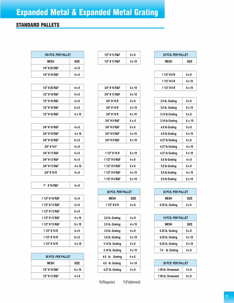
STANDARD PALLETS
R(Regular) F(Flattened)
12
NOMENCLATURE
C.S.F—(hundred square feet) the unit of measure for price andweight.
DIAMOND OR OPENING—This is the description of the open areaformed by strands and bonds. Normally the open area is diamondshaped.
BOND—The point where adjacent strands intersect. The bond isalways twice the width of the strand.
SWD OR SWO—Short way of diamond or short way of opening isthe dimension measured across the sheet in a direction parallel tothe smallest dimension of the diamond.
LWD OR LWO—Long way of diamond or long way of opening is thedimension measured across the sheet in a direction parallel to thelargest dimension of the diamond.
MESH—This is the nominal distance from the mid-point of onebond to the mid-point of the next bond measured across the SWD.Mesh is expressed in inches.
OPENING SIZE—The area enclosed by bonds and strands.
OVERALL THICKNESS—This is the finished thickness and oftendetermines the selection of framing members.
PERCENT OF OPEN AREA—These important relative percentagesare used by designers to calculate the degree with which light andair can pass through a piece of expanded metal.
PITCH—The measurement from a point on one diamond to thesame point on an adjacent diamond.
STRAND—The single metal strip which forms the border of thediamond, or opening. Strand width is the amount of materialadvanced for expanding as differentiated from strand thicknesswhich is the thickness of metal from which the expanded metal isproduced.
STYLE—Is the guage or thickness of metal from which expandedmetal is made. Usually, but not always, this conforms tomanufacturer’s standard guages. Style is expressed by a number.Expanded metal grating style is expressed in lbs. per square foot.
FORMABILITY—Each piece should be able to withstand a 90degree bend with a 1/4 inch inside radius in either direction,without fracture.
LEVELING—All expanded metal products except grating are leveledafter having been expanded.
OUT OF SQUARE—Expanded metal sheets are generally notperfectly square when finished. Sheets must be resquared byshearing on all sides for perfect squareness.
Reshearing at the mill is not usually done since most sheets aresheared to size to be within tolerance.
CAMBER—Bow in sheet. It is measured by placing a straight edgealong the concave side of the sheet parallel to LWD, touching bothends of the sheet. The maximum distance between the edge of theexpanded metal and the straight edge is the camber. A sheet maybe within a width tolerance and still have camber.
PRODUCT DEFINITION
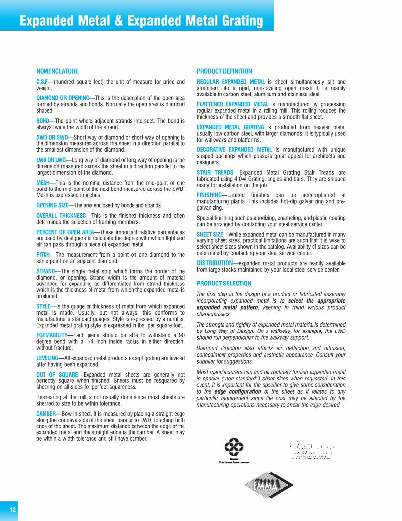
REGULAR EXPANDED METAL is sheet simultaneously slit andstretched into a rigid, non-raveling open mesh. It is readilyavailable in carbon steel, aluminum and stainless steel.
FLATTENED EXPANDED METAL is manufactured by processingregular expanded metal in a rolling mill. This rolling reduces thethickness of the sheet and provides a smooth flat sheet.
EXPANDED METAL GRATING is produced from heavier plate,usually low-carbon steel, with larger diamonds. It is typically usedfor walkways and platforms.
DECORATIVE EXPANDED METAL is manufactured with uniqueshaped openings which possess great appeal for architects anddesigners.
STAIR TREADS—Expanded Metal Grating Stair Treads arefabricated using 4.0# Grating, angles and bars. They are shippedready for installation on the job.
FINISHING—Limited finishes can be accomplished atmanufacturing plants. This includes hot-dip galvanizing and pre-galvanizing.
Special finishing such as anodizing, enameling, and plastic coatingcan be arranged by contacting your steel service center.
SHEET SIZE—While expanded metal can be manufactured in manyvarying sheet sizes, practical limitations are such that it is wise toselect sheet sizes shown in the catalog. Availability of sizes can bedetermined by contacting your steel service center.
DISTRIBUTION—expanded metal products are readily availablefrom large stocks maintained by your local steel service center.
PRODUCT SELECTION
The first step in the design of a product or fabricated assemblyincorporating expanded metal is to select the appropriateexpanded metal pattern, keeping in mind various productcharacteristics.
The strength and rigidity of expanded metal material is determinedby Long Way of Design. On a walkway, for example, the LWDshould run perpendicular to the walkway support.
Diamond direction also affects air deflection and diffusion,concealment properties and aesthetic appearance. Consult yoursupplier for suggestions.
Most manufacturers can and do routinely furnish expanded metalin special (“non-standard”) sheet sizes when requested. In thisevent, it is important for the specifier to give some considerationto the edge configuration of the sheet as it relates to anyparticular requirement since the cost may be affected by themanufacturing operations necessary to shear the edge desired.
Expanded Metal & Expanded Metal Grating

Bar GratingWelded Steel Grating(pages 14–35)
Standard Welded: AMICO®’s welded grating isused universally for walkway and mezzaninedecking applications. It is ideal for most generalindustrial and commercial uses. Standard weldedgrating is generally considered to include gratingwith bearing bars spaced at 1-3/16" or 15/16"and is available in carbon or stainless steel.
Close-Mesh: Close-mesh grating is similar tostandard grating except that the spacing of thebearing bars is closer, ranging from 7/16" to13/16". It is suitable for applications requiringnarrow spacing for aesthetic or functional rea-sons. It is available in carbon or stainless steel.
Railroad: Welded grating with spacings of 1-9/16"and 1-11/16" meet the requirements for AARapproved safety walkway products. This gratingis designed specifically for use as railcar brakesteps, running boards, walkways and platforms.
Heavy-Duty: Heavy-Duty uses thicker (1/4",5/16", 3/8") and deeper bearing bars. Althoughthe tables show bars as deep as 6", deepergrating can be custom fabricated on request.Heavy-Duty is used for airfields, highways,industrial floors, ramps, docks, reinforcedconcrete areas and specialty applications.
Press-Locked Steeland Aluminum Grating(pages 15–21 / steel and pages 41–47 / aluminum)
Because this grating is a system of interlocking,perpendicular bars, it provides a smooth cleanlook ideal for architectural applications such asgrilles, dividers and screens. It is used in thesame structural applications as its welded steeland rectangular aluminum counterparts. Materi-als include carbon steel, stainless steel or alu-minum. Spacings range from 7/16" to 1-3/16".
Swage-Locked Aluminum Grating(pages 37-40)
Swage-locked aluminum grating is manufacturedwith either an “I” or rectangular bearing bar.These bars are permanently locked to the crossrods with a swaging process which reshapesthe rods. Because of the flange width, I-barsreduce the open spaces of the grating yet I-barswage-locked is lighter weight and less costlythan a rectangular bar grating with the same barthickness.
Duo-Grip™ Aluminum Planks(page 48)
Duo-Grip™ planking is a one piece extrudedplank with exceptional strength and stiffness-to-weight ratio due to its I-beam ribs. It is availablein either unpunched, square punched or rectan-gular punched styles to suit lighting and ventila-tion considerations. The design provides con-tinuous walking surface for additional safety.
Riveted Steel and Aluminum Grating(pages 50–51 / steel and pages 52–53 / aluminum)
Riveted grating is especially practical for areaswhere rolling loads are used because of itssmoother surface. It is available in bothaluminum and steel.
Riv-Dexteel®(pages 54–55)
Riv-Dexteel® is a high strength grating whichincorporates a truss style design through the useof a reticulated riveted bar in conjunction with astraight bearing bar. It has been used for nearly75 years as bridge decking, curb inlet grates,industrial flooring, driveways across cul-verts and heavy traffic areas.
13
Material SelectionCarbon Steel: Carbon steel provides aneconomical, high strength grating for use inmost industrial and commercial applications.
Aluminum: Lightweight, corrosion resistant andnon-sparking alloys make aluminum ideal for usein chemical, petroleum, hydro and food process-ing plants, sewage, water and waste treatmentfacilities; munitions plants and other volatileareas; aboard ship; etc.
Stainless Steel: Stainless steel is ideal for use incaustic atmospheres where corrosion resistanceand minimum carbide precipitation are importantconsiderations. It is especially applicable forchemical, food and hydro processing areas.
Painted: One coat of manufacturer’s standardpaint, applied in accord with the manufacturer’sstandard practice. One shop coat of manufac-turer’s standard paint is designed to protect thegrating and/or treads from the elements duringtransit. Meets NAAMM’s Metal Bar Grating Man-ual MBG531-00. (Note: Paint is not intended as afinish coat.) Gratings and/or treads stored at thejobsite shall be covered or under roof. Requiredcovering is not the responsibility of the gratingand/or tread supplier.
Galvanizing: Grating specified to be galvanizedshall have their exposed surfaces zinc-coated bythe hot dip process after fabrication, with acoating of not less than 1.8 oz/ft2 (550 g/m2 ofcoated surface).

14
Steel Bar GratingWelded Steel Bar Grating is the most popular of all grating types due toits strength, cost-efficient production and ease of installation. Universallyused in most general industrial plants as well as commercial buildings, ithas wide applications as walkways, platforms, safety barriers, drainagecovers and ventilation grates.
It is also ideal for use as mezzanine decking since it supports thesame loads as comparable solid flooring. More than that, its cost savingopenness maximizes the circulation of air, light, heat, water and sound,while promoting cleanliness. And, where insurance codes permit, addi-tional sprinklers can often be eliminated. Standard panels are available inwidths of 2', 3' or 4'.
Welded steel bar grating is resistance welded to create a rugged, one-piece constructed panel. The bearing bars are automatically resistancewelded at the contact point with the cross bars and, under a combinationof high heat and pressure, are fused together to form a permanent joint.The cross bars provide a high degree of rigidity, yet retain a smooth flatsurface for free and easy walking.
Press-Locked Steel Bar Grating is often desirable because of itsclean, smooth look and excellent lateral support. It exhibits the samestrength, long life and openness as welded grating, although it is notrecommended for rolling loads. Instead of welding the joints, however,tremendous hydraulic pressure is used to bond the two close-toleranceslotted bars together. Permanent locking is achieved by forcing the deepcross bar into the notched bearing bar.
Further fabrication or galvanizing is not recommended after thematerial leaves AMICO®.
Steel Welded Railroad Grating, in 1-9/16" and 1-11/16" spacings, isAAR (Association of American Railroads) approved and specified forbrake steps, running boards, walkways and platforms for railroad cars.Designed and engineered specifically for railroad use, AMICO-Klemp®
railroad grating is used by both new car and car repair facilities since it isinterchangeable with other AAR approved gratings. The serrated bearingbars provide additional safety and the openness of bar grating minimizesbuild up of snow, ice and other debris.
19-W-4 19-W-2
15-W-4 15-W-2
13-W-4 13-W-2
11-W-4 11-W-2
8-W-4 7-W-4
10-W-4 10-W-2
25-W-4 27-W-4
19-P-4 19-P-2
15-P-4 15-P-2
7-P-2
13-P-4 13-P-2
11-P-4 11-P-2
10-P-4 10-P-2
8-P-4 8-P-2
7-P-4
PRESS-LOCKED STEEL BAR GRATINGSTEEL WELDED RAILROAD GRATING (AAR APPROVED)WELDED STEEL BAR GRATING
Std. Panel width 2'-0 & 3'-04'-0 wide on some styles ofwelded and press-locked
(upon request)
7/16”

15
355 227 158 116 89 700.099 0.155 0.223 0.304 0.397 0.503355 284 237 203 178 158
0.079 0.124 0.179 0.243 0.318 0.402533 341 237 174 133 105
0.099 0.155 0.223 0.304 0.397 0.503533 426 355 305 266 237
0.079 0.124 0.179 0.243 0.318 0.402632 404 281 206 158 125 101 84
0.074 0.116 0.168 0.228 0.298 0.377 0.466 0.563632 505 421 361 316 281 253 230
0.060 0.093 0.134 0.182 0.238 0.302 0.372 0.451947 606 421 309 237 187 152 125
0.074 0.116 0.168 0.228 0.298 0.377 0.466 0.563947 758 632 541 474 421 379 344
0.060 0.093 0.134 0.182 0.238 0.302 0.372 0.451987 632 439 322 247 195 158 130 110 93 81
0.060 0.093 0.134 0.182 0.238 0.302 0.372 0.451 0.536 0.629 0.730987 789 658 564 493 439 395 359 329 304 282
0.048 0.074 0.107 0.146 0.191 0.241 0.298 0.360 0.429 0.504 0.5841480 947 658 483 370 292 237 196 164 140 1210.060 0.093 0.134 0.182 0.238 0.302 0.372 0.451 0.536 0.629 0.7301480 1184 987 846 740 658 592 538 493 455 4230.048 0.074 0.107 0.146 0.191 0.241 0.298 0.360 0.429 0.504 0.5841421 909 632 464 355 281 227 188 158 135 116 89 700.050 0.078 0.112 0.152 0.199 0.251 0.310 0.376 0.447 0.524 0.608 0.794 1.0061421 1137 947 812 711 632 568 517 474 437 406 355 3160.040 0.062 0.089 0.122 0.159 0.201 0.248 0.300 0.358 0.420 0.487 0.636 0.8042132 1364 947 696 533 421 341 282 237 202 174 133 1050.050 0.078 0.112 0.152 0.199 0.251 0.310 0.376 0.447 0.524 0.608 0.794 1.0062132 1705 1421 1218 1066 947 853 775 711 656 609 533 4740.040 0.062 0.089 0.122 0.159 0.201 0.248 0.300 0.358 0.420 0.487 0.636 0.8042901 1857 1289 947 725 573 464 384 322 275 237 181 1430.043 0.067 0.096 0.130 0.170 0.215 0.266 0.322 0.383 0.450 0.521 0.681 0.8622901 2321 1934 1658 1451 1289 1161 1055 967 893 829 725 6450.034 0.053 0.077 0.104 0.136 0.172 0.213 0.257 0.306 0.360 0.417 0.545 0.6893789 2425 1684 1237 947 749 606 501 421 359 309 237 1870.037 0.058 0.084 0.114 0.149 0.189 0.233 0.282 0.335 0.393 0.456 0.596 0.7543789 3032 2526 2165 1895 1684 1516 1378 1263 1166 1083 947 8420.030 0.047 0.067 0.091 0.119 0.151 0.186 0.225 0.268 0.315 0.365 0.477 0.6034796 3069 2132 1566 1199 947 767 634 533 454 392 300 2370.033 0.052 0.074 0.101 0.132 0.168 0.207 0.250 0.298 0.350 0.406 0.530 0.6704796 3837 3197 2741 2398 2132 1918 1744 1599 1476 1370 1199 10660.026 0.041 0.060 0.081 0.106 0.134 0.166 0.200 0.238 0.280 0.324 0.424 0.5365921 3789 2632 1933 1480 1170 947 783 658 561 483 370 2920.030 0.047 0.067 0.091 0.119 0.151 0.186 0.225 0.268 0.315 0.365 0.477 0.6035921 4737 3947 3383 2961 2632 2368 2153 1974 1822 1692 1480 13160.024 0.037 0.054 0.073 0.095 0.121 0.149 0.180 0.215 0.252 0.292 0.381 0.483
19-W-4
19-P-419-P-219-W-4
19-P-419-P-219-W-419-W-219-P-419-P-219-W-419-W-219-P-419-P-219-W-419-W-219-P-419-P-219-W-419-W-219-P-419-P-219-W-419-W-219-P-419-P-219-W-419-W-219-P-419-P-219-W-419-W-219-P-419-P-219-W-419-W-219-P-419-P-219-W-419-W-219-P-419-P-219-W-419-W-219-P-419-P-2
24" 30" 36" 42" 48" 54"
96" 108"
72" 78" 84"
60" 66"
Approx. Sec. ModBar Symbol Weight Per Ft.Size psf Of Width
3/4" x 1/8"
3/4" x 3/16"
1" x 1/8"
1" x 3/16"
1-1/4" x 1/8"
1-1/4" x 3/16"
1-1/2" x 1/8"
1-1/2" x 3/16"
1-3/4" x 3/16"
2" x 3/16"
2-1/4" x 3/16"
2-1/2" x 3/16"
0.118
0.178
0.211
0.316
0.329
0.493
0.474
0.711
0.967
1.263
1.599
1.974
SPAN (Direction of Bearing Bar)
LOAD & DEFLECTION TABLE
UDCDUDCDUDCDUDCDUDCDUDCDUDCDUDCDUDCDUDCDUDCDUDCD
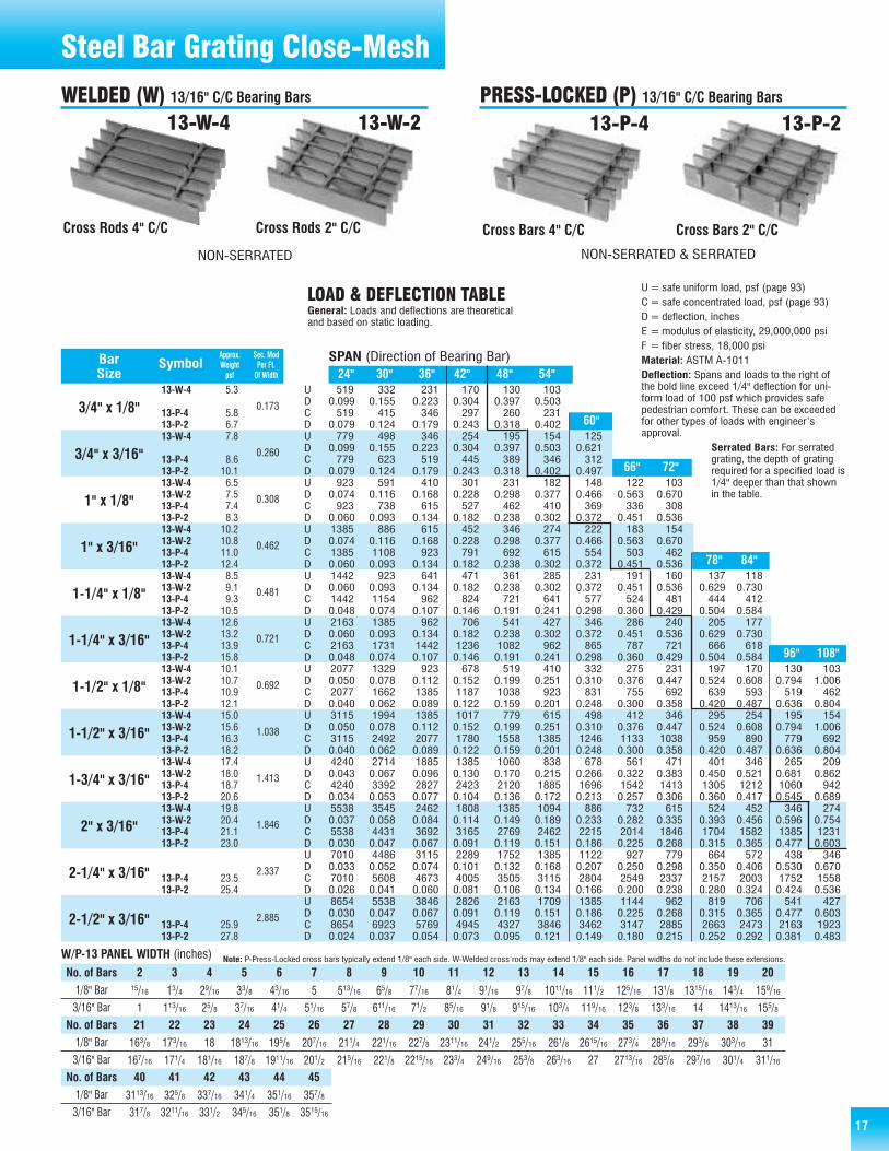
U=safe uniform load, psf (page 93)C= safe concentrated load, psf (page 93)D=deflection, inchesE =modulus of elasticity, 29,000,000 psiF = fiber stress, 18,000 psiMaterial: ASTM A-1011 standardDeflection: Spans and loads to the right ofthe bold line exceed 1/4" deflection for uni-form load of 100 psf which provides safepedestrian comfort. These can be exceededfor other types of loads with engineer’sapproval.
Serrated Bars: For serrated grating, thedepth of grating required for a specifiedload is 1/4" deeper than that shown inthe table.
W/P-19 PANEL WIDTH (inches)No. of Bars 2 3 4 5 6 7 8 9 10 11 12 13 14 15 161/8" Bar
3/16" Bar15/16 21/2 311/16 47/8 61/16 71/4 87/16 95/8 1013/16 12 133/16 143/8 159/16 163/4 1715/16
13/8 29/16 33/4 415/16 61/8 75/16 81/2 911/16 107/8 121/16 131/4 147/16 155/8 1613/16 18
1/8" Bar
3/16" Bar191/8 205/16 211/2 2211/16 237/8 251/16 261/4 277/16 285/8 2913/16 31 323/16 333/8 349/16 353/4
193/16 203/8 219/16 223/4 2315/16 251/8 265/16 271/2 2811/16 297/8 311/16 321/4 337/16 345/8 3513/16
No. of Bars 17 18 19 20 21 22 23 24 25 26 27 28 29 30 31
3.9
4.35.25.6
6.47.85.05.55.46.37.27.88.19.56.16.66.88.18.99.510.212.17.27.77.99.210.511.211.813.812.212.813.515.413.914.515.217.115.516.116.818.717.217.818.520.4
Cross Rods 4" C/C
NON-SERRATED & SERRATED NON-SERRATED & SERRATED
19-W-4
Cross Rods 2" C/C
19-W-2
Cross Bars 2" C/C
19-P-2
Cross Bars 4" C/C
19-P-4
Steel Bar Grating
Note: P-Press-Locked cross bars typically extend 1/8" each side. W-Welded cross rodsmay extend 1/8" each side. Panel widths do not include these extensions.
WELDED (W) 1-3/16" C/C Bearing Bars PRESS-LOCKED (P) 1-3/16" C/C Bearing Bars
General: Loads and deflections are theoreticaland based on static loading.

16
450 288 200 147 113 890.099 0.155 0.223 0.304 0.397 0.503450 360 300 257 225 200
0.079 0.124 0.179 0.243 0.318 0.402675 432 300 220 169 133 108
0.099 0.155 0.223 0.304 0.397 0.503 0.621675 540 450 386 338 300 270
0.079 0.124 0.179 0.243 0.318 0.402 0.497800 512 356 261 200 158 128 106 89
0.074 0.116 0.168 0.228 0.298 0.377 0.466 0.563 0.670800 640 533 457 400 356 320 291 267
0.060 0.093 0.134 0.182 0.238 0.302 0.372 0.451 0.5361200 768 533 392 300 237 192 159 1330.074 0.116 0.168 0.228 0.298 0.377 0.466 0.563 0.6701200 960 800 686 600 533 480 436 4000.060 0.093 0.134 0.182 0.238 0.302 0.372 0.451 0.5361250 800 556 408 313 247 200 165 139 118 1020.060 0.093 0.134 0.182 0.238 0.302 0.372 0.451 0.536 0.629 0.7301250 1000 833 714 625 556 500 455 417 385 3570.048 0.074 0.107 0.146 0.191 0.241 0.298 0.360 0.429 0.504 0.5841875 1200 833 612 469 370 300 248 208 178 1530.060 0.093 0.134 0.182 0.238 0.302 0.372 0.451 0.536 0.629 0.7301875 1500 1250 1071 938 833 750 682 625 577 5360.048 0.074 0.107 0.146 0.191 0.241 0.298 0.360 0.429 0.504 0.5841800 1152 800 588 450 356 288 238 200 170 147 113 890.050 0.078 0.112 0.152 0.199 0.251 0.310 0.376 0.447 0.524 0.608 0.794 1.0061800 1440 1200 1029 900 800 720 655 600 554 514 450 4000.040 0.062 0.089 0.122 0.159 0.201 0.248 0.300 0.358 0.420 0.487 0.636 0.8042700 1728 1200 882 675 533 432 357 300 256 220 169 1330.050 0.078 0.112 0.152 0.199 0.251 0.310 0.376 0.447 0.524 0.608 0.794 1.0062700 2160 1800 1543 1350 1200 1080 982 900 831 771 675 6000.040 0.062 0.089 0.122 0.159 0.201 0.248 0.300 0.358 0.420 0.487 0.636 0.8043675 2352 1633 1200 919 726 588 486 408 348 300 230 1810.043 0.067 0.096 0.130 0.170 0.215 0.266 0.322 0.383 0.450 0.521 0.681 0.8623675 2940 2450 2100 1838 1633 1470 1336 1225 1131 1050 919 8170.034 0.053 0.077 0.104 0.136 0.172 0.213 0.257 0.306 0.360 0.417 0.545 0.6894800 3072 2133 1567 1200 948 768 635 533 454 392 300 2370.037 0.058 0.084 0.114 0.149 0.189 0.233 0.282 0.335 0.393 0.456 0.596 0.7544800 3840 3200 2743 2400 2133 1920 1745 1600 1477 1371 1200 10670.030 0.047 0.067 0.091 0.119 0.151 0.186 0.225 0.268 0.315 0.365 0.477 0.6036075 3888 2700 1984 1519 1200 972 803 675 575 496 380 3000.033 0.052 0.074 0.101 0.132 0.168 0.207 0.250 0.298 0.350 0.406 0.530 0.6706075 4860 4050 3471 3038 2700 2430 2209 2025 1869 1736 1519 13500.026 0.041 0.060 0.081 0.106 0.134 0.166 0.200 0.238 0.280 0.324 0.424 0.5367500 4800 3333 2449 1875 1481 1200 992 833 710 612 469 3700.030 0.047 0.067 0.091 0.119 0.151 0.186 0.225 0.268 0.315 0.365 0.477 0.6037500 6000 5000 4286 3750 3333 3000 2727 2500 2308 2143 1875 16670.024 0.037 0.054 0.073 0.095 0.121 0.149 0.180 0.215 0.252 0.292 0.381 0.483
15-W-4
15-P-415-P215-W-4
15-P-415-P-215-W-415-W-215-P-415-P-215-W-415-W-215-P-415-P-215-W-415-W-215-P-415-P-215-W-415-W-215-P-415-P-215-W-415-W-215-P-415-P-215-W-415-W-215-P-415-P-215-W-415-W-215-P-415-P-215-W-415-W-215-P-415-P-215-W-415-W-215-P-415-P-215-W-415-W-215-P-415-P-2
24" 30" 36" 42" 48" 54"
96" 108"
78" 84"
66" 72"
60"
Approx. Sec. ModBar Symbol Weight Per Ft.Size psf Of Width
3/4" x 1/8"
3/4" x 3/16"
1" x 1/8"
1" x 3/16"
1-1/4" x 1/8"
1-1/4" x 3/16"
1-1/2" x 1/8"
1-1/2" x 3/16"
1-3/4" x 3/16"
2" x 3/16"
2-1/4" x 3/16"
2-1/2" x 3/16"
0.150
0.225
0.267
0.400
0.417
0.625
0.600
0.900
1.225
1.600
2.025
2.500
SPAN (Direction of Bearing Bar)
LOAD & DEFLECTION TABLE
UDCDUDCDUDCDUDCDUDCDUDCDUDCDUDCDUDCDUDCDUDCDUDCD
U=safe uniform load, psf (page 93)C= safe concentrated load, psf (page 93)D=deflection, inchesE =modulus of elasticity, 29,000,000 psiF = fiber stress, 18,000 psiMaterial: ASTM A-1011Deflection: Spans and loads to the right ofthe bold line exceed 1/4" deflection for uni-form load of 100 psf which provides safepedestrian comfort. These can be exceededfor other types of loads with engineer’sapproval.
Serrated Bars: For serratedgrating, the depth of gratingrequired for a specified load is1/4" deeper than that shownin the table.
4.7
5.16.16.9
7.79.16.16.76.57.58.99.69.811.27.58.18.29.511.011.612.314.28.99.49.610.913.113.714.416.315.215.816.518.417.317.918.620.519.420.020.722.621.422.022.724.7
Cross Rods 4" C/C
15-W-4
Cross Rods 2" C/C
15-W-2
Cross Bars 2" C/C
15-P-2
Cross Bars 4" C/C
15-P-4
Steel Bar Grating
2 3 4 5 6 7 8 9 10 11 12 13 14 15 16 17 18 19 20
11/16 2 215/16 37/8 413/16 53/4 611/16 75/8 89/16 91/2 107/16 113/8 125/16 131/4 143/16 151/8 161/16 17 1715/16
11/8 21/16 3 315/16 47/8 513/16 63/4 711/16 85/8 99/16 101/2 117/16 123/8 135/16 141/4 153/16 161/8 171/16 18
187/8 1913/16 203/4 2111/16 225/8 239/16 241/2 257/16 263/8 275/16 281/4 293/16 301/8 311/16 32 3215/16 337/8 3413/16 353/4
1815/16 197/8 2013/16 213/4 2211/16 235/8 249/16 251/2 267/16 273/8 285/16 291/4 303/16 311/8 321/16 33 3315/16 347/8 3513/16
21 22 23 24 25 26 27 28 29 30 31 32 33 34 35 36 37 38 39
W/P-15 PANEL WIDTH (inches) Note: P-Press Locked cross bars typically extend 1/8" each side. W-Welded cross rods may extend 1/8" each side. Panel widths do not include these extensions.
No. of Bars1/8" Bar
3/16" Bar
1/8" Bar
3/16" Bar
No. of Bars
WELDED (W) 15/16" C/C Bearing Bars PRESS-LOCKED (P) 15/16" C/C Bearing Bars
NON-SERRATED & SERRATED NON-SERRATED & SERRATED
General: Loads and deflections are theoreticaland based on static loading.
17
519 332 231 170 130 1030.099 0.155 0.223 0.304 0.397 0.503519 415 346 297 260 231
0.079 0.124 0.179 0.243 0.318 0.402779 498 346 254 195 154 125
0.099 0.155 0.223 0.304 0.397 0.503 0.621779 623 519 445 389 346 312
0.079 0.124 0.179 0.243 0.318 0.402 0.497923 591 410 301 231 182 148 122 103
0.074 0.116 0.168 0.228 0.298 0.377 0.466 0.563 0.670923 738 615 527 462 410 369 336 308
0.060 0.093 0.134 0.182 0.238 0.302 0.372 0.451 0.5361385 886 615 452 346 274 222 183 1540.074 0.116 0.168 0.228 0.298 0.377 0.466 0.563 0.6701385 1108 923 791 692 615 554 503 4620.060 0.093 0.134 0.182 0.238 0.302 0.372 0.451 0.5361442 923 641 471 361 285 231 191 160 137 1180.060 0.093 0.134 0.182 0.238 0.302 0.372 0.451 0.536 0.629 0.7301442 1154 962 824 721 641 577 524 481 444 4120.048 0.074 0.107 0.146 0.191 0.241 0.298 0.360 0.429 0.504 0.5842163 1385 962 706 541 427 346 286 240 205 1770.060 0.093 0.134 0.182 0.238 0.302 0.372 0.451 0.536 0.629 0.7302163 1731 1442 1236 1082 962 865 787 721 666 6180.048 0.074 0.107 0.146 0.191 0.241 0.298 0.360 0.429 0.504 0.5842077 1329 923 678 519 410 332 275 231 197 170 130 1030.050 0.078 0.112 0.152 0.199 0.251 0.310 0.376 0.447 0.524 0.608 0.794 1.0062077 1662 1385 1187 1038 923 831 755 692 639 593 519 4620.040 0.062 0.089 0.122 0.159 0.201 0.248 0.300 0.358 0.420 0.487 0.636 0.8043115 1994 1385 1017 779 615 498 412 346 295 254 195 1540.050 0.078 0.112 0.152 0.199 0.251 0.310 0.376 0.447 0.524 0.608 0.794 1.0063115 2492 2077 1780 1558 1385 1246 1133 1038 959 890 779 6920.040 0.062 0.089 0.122 0.159 0.201 0.248 0.300 0.358 0.420 0.487 0.636 0.8044240 2714 1885 1385 1060 838 678 561 471 401 346 265 2090.043 0.067 0.096 0.130 0.170 0.215 0.266 0.322 0.383 0.450 0.521 0.681 0.8624240 3392 2827 2423 2120 1885 1696 1542 1413 1305 1212 1060 9420.034 0.053 0.077 0.104 0.136 0.172 0.213 0.257 0.306 0.360 0.417 0.545 0.6895538 3545 2462 1808 1385 1094 886 732 615 524 452 346 2740.037 0.058 0.084 0.114 0.149 0.189 0.233 0.282 0.335 0.393 0.456 0.596 0.7545538 4431 3692 3165 2769 2462 2215 2014 1846 1704 1582 1385 12310.030 0.047 0.067 0.091 0.119 0.151 0.186 0.225 0.268 0.315 0.365 0.477 0.6037010 4486 3115 2289 1752 1385 1122 927 779 664 572 438 3460.033 0.052 0.074 0.101 0.132 0.168 0.207 0.250 0.298 0.350 0.406 0.530 0.6707010 5608 4673 4005 3505 3115 2804 2549 2337 2157 2003 1752 15580.026 0.041 0.060 0.081 0.106 0.134 0.166 0.200 0.238 0.280 0.324 0.424 0.5368654 5538 3846 2826 2163 1709 1385 1144 962 819 706 541 4270.030 0.047 0.067 0.091 0.119 0.151 0.186 0.225 0.268 0.315 0.365 0.477 0.6038654 6923 5769 4945 4327 3846 3462 3147 2885 2663 2473 2163 19230.024 0.037 0.054 0.073 0.095 0.121 0.149 0.180 0.215 0.252 0.292 0.381 0.483
13-W-4
13-P-413-P-213-W-4
13-P-413-P-213-W-413-W-213-P-413-P-213-W-413-W-213-P-413-P-213-W-413-W-213-P-413-P-213-W-413-W-213-P-413-P-213-W-413-W-213-P-413-P-213-W-413-W-213-P-413-P-213-W-413-W-213-P-413-P-213-W-413-W-213-P-413-P-2
13-P-413-P-2
13-P-413-P-2
24" 30" 36" 42" 48" 54"
96" 108"
78" 84"
66" 72"
60"
Approx. Sec. ModBar Symbol Weight Per Ft.Size psf Of Width
3/4" x 1/8"
3/4" x 3/16"
1" x 1/8"
1" x 3/16"
1-1/4" x 1/8"
1-1/4" x 3/16"
1-1/2" x 1/8"
1-1/2" x 3/16"
1-3/4" x 3/16"
2" x 3/16"
2-1/4" x 3/16"
2-1/2" x 3/16"
0.173
0.260
0.308
0.462
0.481
0.721
0.692
1.038
1.413
1.846
2.337
2.885
SPAN (Direction of Bearing Bar)
LOAD & DEFLECTION TABLE
UDCDUDCDUDCDUDCDUDCDUDCDUDCDUDCDUDCDUDCDUDCDUDCD
U=safe uniform load, psf (page 93)C= safe concentrated load, psf (page 93)D=deflection, inchesE =modulus of elasticity, 29,000,000 psiF = fiber stress, 18,000 psiMaterial: ASTM A-1011Deflection: Spans and loads to the right ofthe bold line exceed 1/4" deflection for uni-form load of 100 psf which provides safepedestrian comfort. These can be exceededfor other types of loads with engineer’sapproval.
Serrated Bars: For serratedgrating, the depth of gratingrequired for a specified load is1/4" deeper than that shownin the table.
Cross Rods 4" C/C Cross Rods 2" C/C Cross Bars 2" C/CCross Bars 4" C/C
13-W-4 13-W-2 13-P-213-P-4
Steel Bar Grating Close-Mesh
5.3
5.86.77.8
8.610.16.57.57.48.310.210.811.012.48.59.19.310.512.613.213.915.810.110.710.912.115.015.616.318.217.418.018.720.619.820.421.123.0
23.525.4
25.927.8
2 3 4 5 6 7 8 9 10 11 12 13 14 15 16 17 18 19 2015/16 13/4 29/16 33/8 43/16 5 513/16 65/8 77/16 81/4 91/16 97/8 1011/16 111/2 125/16 131/8 1315/16 143/4 159/16
1 113/16 25/8 37/16 41/4 51/16 57/8 611/16 71/2 85/16 91/8 915/16 103/4 119/16 123/8 133/16 14 1413/16 155/8
163/8 173/16 18 1813/16 195/8 207/16 211/4 221/16 227/8 2311/16 241/2 255/16 261/8 2615/16 273/4 289/16 293/8 303/16 31
167/16 171/4 181/16 187/8 1911/16 201/2 215/16 221/8 2215/16 233/4 249/16 253/8 263/16 27 2713/16 285/8 297/16 301/4 311/16
21 22 23 24 25 26 27 28 29 30 31 32 33 34 35 36 37 38 39
3113/16 325/8 337/16 341/4 351/16 357/8
317/8 3211/16 331/2 345/16 351/8 3515/16
40 41 42 43 44 45
W/P-13 PANEL WIDTH (inches) Note: P-Press-Locked cross bars typically extend 1/8" each side. W-Welded cross rods may extend 1/8" each side. Panel widths do not include these extensions.
No. of Bars1/8" Bar
3/16" Bar
1/8" Bar
3/16" Bar
No. of Bars
1/8" Bar
3/16" Bar
No. of Bars
WELDED (W) 13/16" C/C Bearing Bars PRESS-LOCKED (P) 13/16" C/C Bearing Bars
NON-SERRATED NON-SERRATED & SERRATED
General: Loads and deflections are theoreticaland based on static loading.
18
614 393 273 200 153 121 980.099 0.155 0.223 0.304 0.397 0.503 0.621614 491 409 351 307 273 245
0.079 0.124 0.179 0.243 0.318 0.402 0.497920 589 409 301 230 182 147
0.099 0.155 0.223 0.304 0.397 0.503 0.621920 736 614 526 460 409 368
0.079 0.124 0.179 0.243 0.318 0.402 0.4971091 698 485 356 273 215 175 144 1210.074 0.116 0.168 0.228 0.298 0.377 0.466 0.563 0.6701091 873 727 623 545 485 436 397 3640.060 0.093 0.134 0.182 0.238 0.302 0.372 0.451 0.5361636 1047 727 534 409 323 262 216 182 1550.074 0.116 0.168 0.228 0.298 0.377 0.466 0.563 0.670 0.7871636 1309 1091 935 818 727 655 595 545 5030.060 0.093 0.134 0.182 0.238 0.302 0.372 0.451 0.536 0.6291705 1091 758 557 426 337 273 225 189 161 1390.060 0.093 0.134 0.182 0.238 0.302 0.372 0.451 0.536 0.629 0.7301705 1364 1136 974 852 758 682 620 568 524 4870.048 0.074 0.107 0.146 0.191 0.241 0.298 0.360 0.429 0.504 0.5842557 1636 1136 835 639 505 409 338 284 242 209 1600.060 0.093 0.134 0.182 0.238 0.302 0.372 0.451 0.536 0.629 0.730 0.9532557 2045 1705 1461 1278 1136 1023 930 852 787 731 6390.048 0.074 0.107 0.146 0.191 0.241 0.298 0.360 0.429 0.504 0.584 0.7632455 1571 1091 801 614 485 393 325 273 232 200 153 1210.050 0.078 0.112 0.152 0.199 0.251 0.310 0.376 0.447 0.524 0.608 0.794 1.0062455 1964 1636 1403 1227 1091 982 893 818 755 701 614 5450.040 0.062 0.089 0.122 0.159 0.201 0.248 0.300 0.358 0.420 0.487 0.636 0.8043682 2356 1636 1202 920 727 589 487 409 349 301 230 1820.050 0.078 0.112 0.152 0.199 0.251 0.310 0.376 0.447 0.524 0.608 0.794 1.0063682 2945 2455 2104 1841 1636 1473 1339 1227 1133 1052 920 8180.040 0.062 0.089 0.122 0.159 0.201 0.248 0.300 0.358 0.420 0.487 0.636 0.8045011 3207 2227 1636 1253 990 802 663 557 474 409 313 2470.043 0.067 0.096 0.130 0.170 0.215 0.266 0.322 0.383 0.450 0.521 0.681 0.8625011 4009 3341 2864 2506 2227 2005 1822 1670 1542 1432 1253 11140.034 0.053 0.077 0.104 0.136 0.172 0.213 0.257 0.306 0.360 0.417 0.545 0.6896545 4189 2909 2137 1636 1293 1047 866 727 620 534 409 3230.037 0.058 0.084 0.114 0.149 0.189 0.233 0.282 0.335 0.393 0.456 0.596 0.7546545 5236 4364 3740 3273 2909 2618 2380 2182 2014 1870 1636 14550.030 0.047 0.067 0.091 0.119 0.151 0.186 0.225 0.268 0.315 0.365 0.477 0.6038284 5302 3682 2705 2071 1636 1325 1095 920 784 676 518 4090.033 0.052 0.074 0.101 0.132 0.168 0.207 0.250 0.298 0.350 0.406 0.530 0.6708284 6627 5523 4734 4142 3682 3314 3012 2761 2549 2367 2071 18410.026 0.041 0.060 0.081 0.106 0.134 0.166 0.200 0.238 0.280 0.324 0.424 0.53610227 6545 4545 3340 2557 2020 1636 1352 1136 968 835 639 5050.030 0.047 0.067 0.091 0.119 0.151 0.186 0.225 0.268 0.315 0.365 0.477 0.60310227 8182 6818 5844 5114 4545 4091 3719 3409 3147 2922 2557 22730.024 0.037 0.054 0.073 0.095 0.121 0.149 0.180 0.215 0.252 0.292 0.381 0.483
11-W-4
11-P-411-P-211-W-4
11-P-411-P-211-W-411-W-211-P-411-P-211-W-411-W-211-P-411-P-211-W-411-W-211-P-411-P-211-W-411-W-211-P-411-P-211-W-411-W-211-P-411-P-211-W-411-W-211-P-411-P-211-W-411-W-211-P-411-P-211-W-411-W-211-P-411-P-211-W-411-W-211-P-411-P-211-W-411-W-211-P-411-P-2
24" 30" 36" 42" 48" 54" 60"
84"
96"
108"
78"
66" 72"
Approx. Sec. ModBar Symbol Weight Per Ft.Size psf Of Width
3/4" x 1/8"
3/4" x 3/16"
1" x 1/8"
1" x 3/16"
1-1/4" x 1/8"
1-1/4" x 3/16"
1-1/2" x 1/8"
1-1/2" x 3/16"
1-3/4" x 3/16"
2" x 3/16"
2-1/4" x 3/16"
2-1/2" x 3/16"
0.205
0.307
0.364
0.545
0.568
0.852
0.818
1.227
1.670
2.182
2.761
3.409
SPAN (Direction of Bearing Bar)
LOAD & DEFLECTION TABLE
UDCDUDCDUDCDUDCDUDCDUDCDUDCDUDCDUDCDUDCDUDCDUDCD
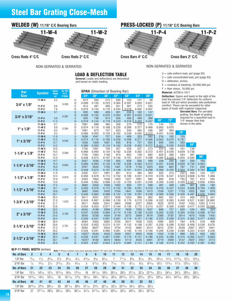
U=safe uniform load, psf (page 93)C= safe concentrated load, psf (page 93)D=deflection, inchesE =modulus of elasticity, 29,000,000 psiF = fiber stress, 18,000 psiMaterial: ASTM A-1011Deflection: Spans and loads to the right of thebold line exceed 1/4" deflection for uniformload of 100 psf which provides safe pedestriancomfort. These can be exceeded for othertypes of loads with engineer’sapproval.
Serrated Bars: For serratedgrating, the depth of gratingrequired for a specified load is1/4" deeper than thatshown in the table.
6.2
6.67.69.1
9.911.38.18.68.59.411.912.512.714.210.010.510.712.014.715.316.017.911.912.412.613.917.518.118.820.720.421.021.723.623.223.824.526.426.026.627.329.228.829.430.132.0
Cross Rods 4" C/C Cross Rods 2" C/C Cross Bars 2" C/CCross Bars 4" C/C
11-W-4 11-W-2 11-P-211-P-4
Steel Bar Grating Close-Mesh
2 3 4 5 6 7 8 9 10 11 12 13 14 15 16 17 18 19 2013/16 11/2 23/16 27/8 39/16 41/4 415/16 55/8 65/16 7 711/16 83/8 91/16 93/4 107/16 111/8 1113/16 121/2 133/167/8 19/16 21/4 215/16 35/8 45/16 5 511/16 63/8 71/16 73/4 87/16 91/8 913/16 101/2 113/16 117/8 129/16 131/4
137/8 149/16 151/4 1515/16 165/8 175/16 18 1811/16 193/8 201/16 203/4 217/16 221/8 2213/16 231/2 243/16 247/8 259/16 261/4
1315/16 145/8 155/16 16 1611/16 173/8 181/16 183/4 197/16 201/8 2013/16 211/2 223/16 227/8 239/16 241/4 2415/16 255/8 265/16
21 22 23 24 25 26 27 28 29 30 31 32 33 34 35 36 37 38 39
2615/16 275/8 285/16 29 2911/16 303/8 311/16 313/4 327/16 331/8 3313/16 341/2 353/16 357/8
27 2711/16 283/8 291/16 293/4 307/16 311/8 3113/16 321/2 333/16 337/8 349/16 351/4 3515/16
40 41 42 43 44 45 46 47 48 49 50 51 52 53
W/P-11 PANEL WIDTH (inches) Note: P-Press-Locked cross bars typically extend 1/8" each side. W-Welded cross rods may extend 1/8" each side. Panel widths do not include these extensions.
No. of Bars1/8" Bar
3/16" Bar
1/8" Bar
3/16" Bar
No. of Bars
1/8" Bar
3/16" Bar
No. of Bars
WELDED (W) 11/16" C/C Bearing Bars PRESS-LOCKED (P) 11/16" C/C Bearing Bars
General: Loads and deflections are theoreticaland based on static loading.
NON-SERRATED & SERRATED NON-SERRATED & SERRATED

19
675 432 300 220 169 133 1080.099 0.155 0.223 0.304 0.397 0.503 0.621675 540 450 386 338 300 270
0.079 0.124 0.179 0.243 0.318 0.402 0.4971013 648 450 331 253 200 162 1340.099 0.155 0.223 0.304 0.397 0.503 0.621 0.7511013 810 675 579 506 450 405 3680.079 0.124 0.179 0.243 0.318 0.402 0.497 0.6011200 768 533 392 300 237 192 159 1330.074 0.116 0.168 0.228 0.298 0.377 0.466 0.563 0.6701200 960 800 686 600 533 480 436 4000.060 0.093 0.134 0.182 0.238 0.302 0.372 0.451 0.5361800 1152 800 588 450 356 288 238 200 1700.074 0.116 0.168 0.228 0.298 0.377 0.466 0.563 0.670 0.7871800 1440 1200 1029 900 800 720 655 600 5540.060 0.093 0.134 0.182 0.238 0.302 0.372 0.451 0.536 0.6291875 1200 833 612 469 370 300 248 208 178 1530.060 0.093 0.134 0.182 0.238 0.302 0.372 0.451 0.536 0.629 0.7301875 1500 1250 1071 938 833 750 682 625 577 5360.048 0.074 0.107 0.146 0.191 0.241 0.298 0.360 0.429 0.504 0.5842813 1800 1250 918 703 556 450 372 313 266 230 1760.060 0.093 0.134 0.182 0.238 0.302 0.372 0.451 0.536 0.629 0.730 0.9532813 2250 1875 1607 1406 1250 1125 1023 938 865 804 7030.048 0.074 0.107 0.146 0.191 0.241 0.298 0.360 0.429 0.504 0.584 0.7632700 1728 1200 882 675 533 432 357 300 256 220 169 1330.050 0.078 0.112 0.152 0.199 0.251 0.310 0.376 0.447 0.524 0.608 0.794 1.0062700 2160 1800 1543 1350 1200 1080 982 900 831 771 675 6000.040 0.062 0.089 0.122 0.159 0.201 0.248 0.300 0.358 0.420 0.487 0.636 0.8044050 2592 1800 1322 1013 800 648 536 450 383 331 253 2000.050 0.078 0.112 0.152 0.199 0.251 0.310 0.376 0.447 0.524 0.608 0.794 1.0064050 3240 2700 2314 2025 1800 1620 1473 1350 1246 1157 1013 9000.040 0.062 0.089 0.122 0.159 0.201 0.248 0.300 0.358 0.420 0.487 0.636 0.8045513 3528 2450 1800 1378 1089 882 729 613 522 450 345 2720.043 0.067 0.096 0.130 0.170 0.215 0.266 0.322 0.383 0.450 0.521 0.681 0.8625513 4410 3675 3150 2756 2450 2205 2005 1838 1696 1575 1378 12250.034 0.053 0.077 0.104 0.136 0.172 0.213 0.257 0.306 0.360 0.417 0.545 0.6897200 4608 3200 2351 1800 1422 1152 952 800 682 588 450 3560.037 0.058 0.084 0.114 0.149 0.189 0.233 0.282 0.335 0.393 0.456 0.596 0.7547200 5760 4800 4114 3600 3200 2880 2618 2400 2215 2057 1800 16000.030 0.047 0.067 0.091 0.119 0.151 0.186 0.225 0.268 0.315 0.365 0.477 0.6039113 5832 4050 2976 2278 1800 1458 1205 1013 863 744 570 4500.033 0.052 0.074 0.101 0.132 0.168 0.207 0.250 0.298 0.350 0.406 0.530 0.6709113 7290 6075 5207 4556 4050 3645 3314 3038 2804 2604 2278 20250.026 0.041 0.060 0.081 0.106 0.134 0.166 0.200 0.238 0.280 0.324 0.424 0.53611250 7200 5000 3673 2813 2222 1800 1488 1250 1065 918 703 5560.030 0.047 0.067 0.091 0.119 0.151 0.186 0.225 0.268 0.315 0.365 0.477 0.60311250 9000 7500 6429 5625 5000 4500 4091 3750 3462 3214 2813 25000.024 0.037 0.054 0.073 0.095 0.121 0.149 0.180 0.215 0.252 0.292 0.381 0.483
10-W-4
10-P-410-P-210-W-4
10-P-410-P-210-W-410-W-210-P-410-P-210-W-410-W-210-P-410-P-210-W-410-W-210-P-410-P-210-W-410-W-210-P-410-P-210-W-410-W-210-P-410-P-210-W-410-W-210-P-410-P-210-W-410-W-210-P-410-P-210-W-410-W-210-P-410-P-210-W-410-W-210-P-410-P-210-W-410-W-210-P-410-P-2
24" 30" 36" 42" 48" 54" 60"
72"
78"
84"
96"
108"
66"
Approx. Sec. ModBar Symbol Weight Per Ft.Size psf Of Width
3/4" x 1/8"
3/4" x 3/16"
1" x 1/8"
1" x 3/16"
1-1/4" x 1/8"
1-1/4" x 3/16"
1-1/2" x 1/8"
1-1/2" x 3/16"
1-3/4" x 3/16"
2" x 3/16"
2-1/4" x 3/16"
2-1/2" x 3/16"
0.225
0.338
0.400
0.600
0.625
0.938
0.900
1.350
1.838
2.400
3.038
3.750
SPAN (Direction of Bearing Bar)
LOAD & DEFLECTION TABLE
UDCDUDCDUDCDUDCDUDCDUDCDUDCDUDCDUDCDUDCDUDCDUDCD
U=safe uniform load, psf (page 93)C= safe concentrated load, psf (page 93)D=deflection, inchesE =modulus of elasticity, 29,000,000 psiF = fiber stress, 18,000 psiMaterial: ASTM A-1011Deflection: Spans and loads to the right ofthe bold line exceed 1/4" deflection for uni-form load of 100 psf which provides safe
pedestrian comfort. These can beexceeded for other types of loads withengineer’sapproval.
Serrated Bars: For serratedgrating, the depth of gratingrequired for a specified load is1/4" deeper than that
shown in the table.
6.8
7.28.19.9
10.712.28.89.49.210.213.013.613.815.310.911.411.612.916.116.717.419.313.013.513.715.019.219.820.522.422.322.923.625.525.426.026.728.628.529.129.831.731.632.232.934.8
Cross Rods 4" C/C Cross Rods 2" C/C Cross Bars 2" C/CCross Bars 4" C/C
10-W-4 10-W-2 10-P-210-P-4
Steel Bar Grating Close-Mesh
2 3 4 5 6 7 8 9 10 11 12 13 14 15 16 17 18 19 203/4 13/8 2 25/8 31/4 37/8 41/2 51/8 53/4 63/8 7 75/8 81/4 87/8 91/2 101/8 103/4 113/8 1213/16 17/16 21/16 211/16 35/16 315/16 49/16 53/16 513/16 67/16 71/16 711/16 85/16 815/16 99/16 103/16 1013/16 117/16 121/16
125/8 131/4 137/8 141/2 151/8 153/4 163/8 17 175/8 181/4 187/8 191/2 201/8 203/4 213/8 22 225/8 231/4 237/8
1211/16 135/16 1315/16 149/16 153/16 1513/16 167/16 171/16 1711/16 185/16 1815/16 199/16 203/16 2013/16 217/16 221/16 2211/16 235/16 2315/16
21 22 23 24 25 26 27 28 29 30 31 32 33 34 35 36 37 38 39
241/2 251/8 253/4 263/8 27 275/8 281/4 287/8 291/2 301/8 303/4 313/8 32 325/8 331/4 337/8 341/2 351/8 353/4
249/16 253/16 2513/16 267/16 271/16 2711/16 285/16 2815/16 299/16 303/16 3013/16 317/16 321/16 3211/16 335/16 3315/16 349/16 353/16 3513/16
40 41 42 43 44 45 46 47 48 49 50 51 52 53 54 55 56 57 58
W/P-10 PANEL WIDTH (inches) Note: P-Press-Locked cross bars typically extend 1/8" each side. W-Welded cross rods may extend 1/8" each side. Panel widths do not include these extensions.
No. of Bars1/8" Bar
3/16" Bar
1/8" Bar
3/16" Bar
No. of Bars
1/8" Bar
3/16" Bar
No. of Bars
WELDED (W) 5/8" C/C of Bearing Bars PRESS-LOCKED (P) 5/8" C/C of Bearing Bars
NON-SERRATED & SERRATED NON-SERRATED & SERRATED
General: Loads and deflections are theoreticaland based on static loading.

20
844 540 375 276 211 167 1350.099 0.155 0.223 0.304 0.397 0.503 0.621844 675 563 482 422 375 338
0.079 0.124 0.179 0.243 0.318 0.402 0.4971266 810 563 413 316 250 203 1670.099 0.155 0.223 0.304 0.397 0.503 0.621 0.7511266 1013 844 723 633 563 506 4600.079 0.124 0.179 0.243 0.318 0.402 0.497 0.6011500 960 667 490 375 296 240 198 1670.074 0.116 0.168 0.228 0.298 0.377 0.466 0.563 0.6701500 1200 1000 857 750 667 600 545 5000.060 0.093 0.134 0.182 0.238 0.302 0.372 0.451 0.5362250 1440 1000 735 563 444 360 298 250 2130.074 0.116 0.168 0.228 0.298 0.377 0.466 0.563 0.670 0.7872250 1800 1500 1286 1125 1000 900 818 750 6920.060 0.093 0.134 0.182 0.238 0.302 0.372 0.451 0.536 0.6292344 1500 1042 765 586 463 375 310 260 222 1910.060 0.093 0.134 0.182 0.238 0.302 0.372 0.451 0.536 0.629 0.7302344 1875 1563 1339 1172 1042 938 852 781 721 6700.048 0.074 0.107 0.146 0.191 0.241 0.298 0.360 0.429 0.504 0.5843516 2250 1563 1148 879 694 563 465 391 333 287 220 1740.060 0.093 0.134 0.182 0.238 0.302 0.372 0.451 0.536 0.629 0.730 0.953 1.2073516 2813 2344 2009 1758 1563 1406 1278 1172 1082 1004 879 7810.048 0.074 0.107 0.146 0.191 0.241 0.298 0.360 0.429 0.504 0.584 0.763 0.9653375 2160 1500 1102 844 667 540 446 375 320 276 211 1670.050 0.078 0.112 0.152 0.199 0.251 0.310 0.376 0.447 0.524 0.608 0.794 1.0063375 2700 2250 1929 1688 1500 1350 1227 1125 1038 964 844 7500.040 0.062 0.089 0.122 0.159 0.201 0.248 0.300 0.358 0.420 0.487 0.636 0.8045063 3240 2250 1653 1266 1000 810 669 563 479 413 316 2500.050 0.078 0.112 0.152 0.199 0.251 0.310 0.376 0.447 0.524 0.608 0.794 1.0065063 4050 3375 2893 2531 2250 2025 1841 1688 1558 1446 1266 11250.040 0.062 0.089 0.122 0.159 0.201 0.248 0.300 0.358 0.420 0.487 0.636 0.8046891 4410 3063 2250 1723 1361 1103 911 766 652 563 431 3400.043 0.067 0.096 0.130 0.170 0.215 0.266 0.322 0.383 0.450 0.521 0.681 0.8626891 5513 4594 3938 3445 3063 2756 2506 2297 2120 1969 1723 15310.034 0.053 0.077 0.104 0.136 0.172 0.213 0.257 0.306 0.360 0.417 0.545 0.6899000 5760 4000 2939 2250 1778 1440 1190 1000 852 735 563 4440.037 0.058 0.084 0.114 0.149 0.189 0.233 0.282 0.335 0.393 0.456 0.596 0.7549000 7200 6000 5143 4500 4000 3600 3273 3000 2769 2571 2250 20000.030 0.047 0.067 0.091 0.119 0.151 0.186 0.225 0.268 0.315 0.365 0.477 0.60311391 7290 5063 3719 2848 2250 1823 1506 1266 1078 930 712 5630.033 0.052 0.074 0.101 0.132 0.168 0.207 0.250 0.298 0.350 0.406 0.530 0.67011391 9113 7594 6509 5695 5063 4556 4142 3797 3505 3254 2848 25310.026 0.041 0.060 0.081 0.106 0.134 0.166 0.200 0.238 0.280 0.324 0.424 0.53614063 9000 6250 4592 3516 2778 2250 1860 1563 1331 1148 879 6940.030 0.047 0.067 0.091 0.119 0.151 0.186 0.225 0.268 0.315 0.365 0.477 0.60314063 11250 9375 8036 7031 6250 5625 5114 4688 4327 4018 3516 31250.024 0.037 0.054 0.073 0.095 0.121 0.149 0.180 0.215 0.252 0.292 0.381 0.483
8-W-4
8-P-48-P-28-W-4
8-P-48-P-28-W-4
8-P-48-P-28-W-4
8-P-48-P-28-W-4
8-P-48-P-28-W-4
8-P-48-P-28-W-4
8-P-48-P-28-W-4
8-P-48-P-2
8-P-48-P-2
8-P-48-P-2
8-P-48-P-2
8-P-48-P-2
24" 30" 36" 42" 48" 54" 60"
96" 108"
84"
72"
78"
66"
Approx. Sec. ModBar Symbol Weight Per Ft.Size psf Of Width
3/4" x 1/8"
3/4" x 3/16"
1" x 1/8"
1" x 3/16"
1-1/4" x 1/8"
1-1/4" x 3/16"
1-1/2" x 1/8"
1-1/2" x 3/16"
1-3/4" x 3/16"
2" x 3/16"
2-1/4" x 3/16"
2-1/2" x 3/16"
0.281
0.422
0.500
0.750
0.781
1.172
1.125
1.688
2.297
3.000
3.797
4.688
SPAN (Direction of Bearing Bar)
LOAD & DEFLECTION TABLE
UDCDUDCDUDCDUDCDUDCDUDCDUDCDUDCDUDCDUDCDUDCDUDCD
U=safe uniform load, psf (page 93)C= safe concentrated load, psf (page 93)D=deflection, inchesE =modulus of elasticity, 29,000,000 psiF = fiber stress, 18,000 psiMaterial: ASTM A-1011Deflection: Spans and loads to the right ofthe bold line exceed 1/4" deflection for uni-form load of 100 psf which provides safe
pedestrian comfort. These can beexceeded for other types of loads withengineer’sapproval.
Serrated Bars: For serratedgrating, the depth of gratingrequired for a specified load is1/4" deeper than that
shown in the table.
W/P-8 PANEL WIDTH (inches)2 3 4 5 6 7 8 9 10 11 12 13 14 15 16 17 18 19 20 21 22 23 24 25 26 27 28 295/8 11/8 15/8 21/8 25/8 31/8 35/8 41/8 45/8 51/8 55/8 61/8 65/8 71/8 75/8 81/8 85/8 91/8 95/8 101/8 105/8 111/8 115/8 121/8 125/8 131/8 135/8 141/811/16 13/16 111/16 23/16 211/16 33/16 311/16 43/16 411/16 53/16 511/16 63/16 611/16 73/16 711/16 83/16 811/16 93/16 911/16 103/16 1011/16 113/16 1111/16 123/16 1211/16 133/16 1311/16 143/1630 31 32 33 34 35 36 37 38 39 40 41 42 43 44 45 46 47 48 49 50 51 52 53 54 55 56 57
145/8 151/8 155/8 161/8 165/8 171/8 175/8 181/8 185/8 191/8 195/8 201/8 205/8 211/8 215/8 221/8 225/8 231/8 235/8 241/8 245/8 251/8 255/8 261/8 265/8 271/8 275/8 281/8
1411/16 153/16 1511/16 163/16 1611/16 173/16 1711/16 183/16 1811/16 193/16 1911/16 203/16 2011/16 213/16 2111/16 223/16 2211/16 233/16 2311/16 243/16 2411/16 253/16 2511/16 263/16 2611/16 273/16 2711/16 283/1658 59 60 61 62 63 64 65 66 67 68 69 70 71 72 73
285/8 291/8 295/8 301/8 305/8 311/8 315/8 321/8 325/8 331/8 335/8 341/8 345/8 351/8 355/8 361/8
2811/16 293/16 2911/16 303/16 3011/16 313/16 3111/16 323/16 3211/16 333/16 3311/16 343/16 3411/16 353/16 3511/16 363/16
8.3
8.79.610.9
13.014.410.9
11.312.216.0
16.918.313.4
14.215.419.9
21.223.116.0
16.718.223.8
25.127.0
28.930.8
32.834.7
36.638.5
40.542.4
Cross Rods 4" C/C Cross Bars 2" C/CCross Bars 4" C/C
8-W-4
Welded PanelsMax 2'-0 Width
8-P-28-P-4
Steel Bar Grating Close-Mesh
Note: P-Press-Locked cross bars typically extend 1/8" each side. W-Welded cross rods may extend 1/8" each side. Panel widths do not include these extensions.
No. of Bars1/8" Bar
3/16" Bar
1/8" Bar
3/16" Bar
No. of Bars
1/8" Bar
3/16" Bar
No. of Bars
WELDED (W) 1/2" C/C Bearing Bars PRESS-LOCKED (P) 1/2" C/C Bearing Bars
General: Loads and deflections are theoreticaland based on static loading.
NON-SERRATED ONLY NON-SERRATED & SERRATED
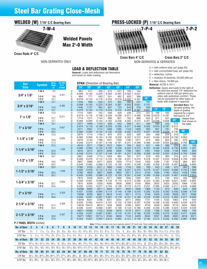
21
964 617 429 315 241 190 1540.099 0.155 0.223 0.304 0.397 0.503 0.621964 771 643 551 482 429 386
0.079 0.124 0.179 0.243 0.318 0.402 0.4971446 926 643 472 362 286 231 1910.099 0.155 0.223 0.304 0.397 0.503 0.621 0.7511446 1157 964 827 723 643 579 5260.079 0.124 0.179 0.243 0.318 0.402 0.497 0.6011714 1097 762 560 429 339 274 227 190 1620.074 0.116 0.168 0.228 0.298 0.377 0.466 0.563 0.670 0.7871714 1371 1143 980 857 762 686 623 571 5270.060 0.093 0.134 0.182 0.238 0.302 0.372 0.451 0.536 0.6292571 1646 1143 840 643 508 411 340 286 243 2100.074 0.116 0.168 0.228 0.298 0.377 0.466 0.563 0.670 0.787 0.9122571 2057 1714 1469 1286 1143 1029 935 857 791 7350.060 0.093 0.134 0.182 0.238 0.302 0.372 0.451 0.536 0.629 0.7302679 1714 1190 875 670 529 429 354 298 254 219 1670.060 0.093 0.134 0.182 0.238 0.302 0.372 0.451 0.536 0.629 0.730 0.9532679 2143 1786 1531 1339 1190 1071 974 893 824 765 6700.048 0.074 0.107 0.146 0.191 0.241 0.298 0.360 0.429 0.504 0.584 0.7634018 2571 1786 1312 1004 794 643 531 446 380 328 251 1980.060 0.093 0.134 0.182 0.238 0.302 0.372 0.451 0.536 0.629 0.730 0.953 1.2074018 3214 2679 2296 2009 1786 1607 1461 1339 1236 1148 1004 8930.048 0.074 0.107 0.146 0.191 0.241 0.298 0.360 0.429 0.504 0.584 0.763 0.9653857 2469 1714 1259 964 762 617 510 429 365 315 241 1900.050 0.078 0.112 0.152 0.199 0.251 0.310 0.376 0.447 0.524 0.608 0.794 1.0063857 3086 2571 2204 1929 1714 1543 1403 1286 1187 1102 964 8570.040 0.062 0.089 0.122 0.159 0.201 0.248 0.300 0.358 0.420 0.487 0.636 0.8045786 3703 2571 1889 1446 1143 926 765 643 548 472 362 2860.050 0.078 0.112 0.152 0.199 0.251 0.310 0.376 0.447 0.524 0.608 0.794 1.0065786 4629 3857 3306 2893 2571 2314 2104 1929 1780 1653 1446 12860.040 0.062 0.089 0.122 0.159 0.201 0.248 0.300 0.358 0.420 0.487 0.636 0.8047875 5040 3500 2571 1969 1556 1260 1041 875 746 643 492 3890.043 0.067 0.096 0.130 0.170 0.215 0.266 0.322 0.383 0.450 0.521 0.681 0.8627875 6300 5250 4500 3938 3500 3150 2864 2625 2423 2250 1969 17500.034 0.053 0.077 0.104 0.136 0.172 0.213 0.257 0.306 0.360 0.417 0.545 0.68910286 6583 4571 3359 2571 2032 1646 1360 1143 974 840 643 5080.037 0.058 0.084 0.114 0.149 0.189 0.233 0.282 0.335 0.393 0.456 0.596 0.75410286 8229 6857 5878 5143 4571 4114 3740 3429 3165 2939 2571 22860.030 0.047 0.067 0.091 0.119 0.151 0.186 0.225 0.268 0.315 0.365 0.477 0.60313018 8331 5786 4251 3254 2571 2083 1721 1446 1232 1063 814 6430.033 0.052 0.074 0.101 0.132 0.168 0.207 0.250 0.298 0.350 0.406 0.530 0.67013018 10414 8679 7439 6509 5786 5207 4734 4339 4005 3719 3254 28930.026 0.041 0.060 0.081 0.106 0.134 0.166 0.200 0.238 0.280 0.324 0.424 0.53616071 10286 7143 5248 4018 3175 2571 2125 1786 1522 1312 1004 7940.030 0.047 0.067 0.091 0.119 0.151 0.186 0.225 0.268 0.315 0.365 0.477 0.60316071 12857 10714 9184 8036 7143 6429 5844 5357 4945 4592 4018 35710.024 0.037 0.054 0.073 0.095 0.121 0.149 0.180 0.215 0.252 0.292 0.381 0.483
7-W-4
7-P-47-P-27-W-4
7-P-47-P-27-W-4
7-P-47-P-27-W-4
7-P-47-P-27-W-4
7-P-47-P-27-W-4
7-P-47-P-27-W-4
7-P-47-P-27-W-4
7-P-47-P-2
7-P-47-P-2
7-P-47-P-2
7-P-47-P-2
7-P-47-P-2
24" 30" 36" 42" 48" 54" 60"
84"
96"
108"
72" 78"
66"
Approx. Sec. ModBar Symbol Weight Per Ft.Size psf Of Width
3/4" x 1/8"
3/4" x 3/16"
1" x 1/8"
1" x 3/16"
1-1/4" x 1/8"
1-1/4" x 3/16"
1-1/2" x 1/8"
1-1/2" x 3/16"
1-3/4" x 3/16"
2" x 3/16"
2-1/4" x 3/16"
2-1/2" x 3/16"
0.321
0.482
0.571
0.857
0.893
1.339
1.286
1.929
2.625
3.429
4.339
5.357
SPAN (Direction of Bearing Bar)
UDCDUDCDUDCDUDCDUDCDUDCDUDCDUDCDUDCDUDCDUDCDUDCD
U=safe uniform load, psf (page 93)C= safe concentrated load, psf (page 93)D=deflection, inchesE =modulus of elasticity, 29,000,000 psiF = fiber stress, 18,000 psiMaterial: ASTM A-1011Deflection: Spans and loads to the right of
the bold line exceed 1/4" deflection foruniform load of 100 psf which pro-vides safe pedestrian comfort. Thesecan be exceeded for other types ofloads with engineer’s approval.
Serrated Bars: Forserrated grating, thedepth of gratingrequired for a speci-fied load is 1/4"
deeper thanthat shown inthe table.
9.3
9.810.713.7
14.616.112.3
12.713.718.1
19.020.515.3
16.017.322.5
23.925.818.1
18.920.226.9
28.330.2
32.734.6
37.139.0
41.543.4
45.947.8
P-7 PANEL WIDTH (inches)2 3 4 5 6 7 8 9 10 11 12 13 14 15 16 17 18 19 20 21 22 23 24 25 26 27 28 299/16 1 17/16 17/8 25/16 23/4 33/16 35/8 41/16 41/2 415/16 53/8 513/16 61/4 611/16 71/8 79/16 8 87/16 87/8 95/16 93/4 103/16 105/8 111/16 111/2 1115/16 123/85/8 11/16 11/2 115/16 23/8 213/16 31/4 311/16 41/8 49/16 5 57/16 57/8 65/16 63/4 73/16 75/8 81/16 81/2 815/16 93/8 913/16 101/4 1011/16 111/8 119/16 12 127/1630 31 32 33 34 35 36 37 38 39 40 41 42 43 44 45 46 47 48 49 50 51 52 53 54 55 56 57
1213/16 131/4 1311/16 141/8 149/16 15 157/16 157/8 165/16 163/4 173/16 175/8 181/16 181/2 1815/16 193/8 1913/16 201/4 2011/16 211/8 219/16 22 227/16 227/8 235/16 233/4 243/16 245/8
127/8 135/16 133/4 143/16 145/8 151/16 151/2 1515/16 163/8 1613/16 171/4 1711/16 181/8 189/16 19 197/16 197/8 205/16 203/4 213/16 215/8 221/16 221/2 2215/16 233/8 2313/16 241/4 2411/1658 59 60 61 62 63 64 65 66 67 68 69 70 71 72 73 74 75 76 77 78 79 80 81 82 83
251/16 251/2 2515/16 263/8 2613/16 271/4 2711/16 281/8 289/16 29 297/16 297/8 305/16 303/4 313/16 315/8 321/16 321/2 3215/16 333/8 3313/16 341/4 3411/16 351/8 359/16 36
251/8 259/16 26 267/16 267/8 275/16 273/4 283/16 285/8 291/16 291/2 2915/16 303/8 3013/16 311/4 3111/16 321/8 329/16 33 337/16 337/8 345/16 343/4 353/16 355/8 361/16
Cross Bars 2" C/CCross Bars 4" C/C
7-P-27-P-4
Steel Bar Grating Close-Mesh
Note: P-Press-Locked cross bars typically extend 1/8" each side. Panel widths do not include these extensions.
No. of Bars1/8" Bar
3/16" Bar
1/8" Bar
3/16" Bar
No. of Bars
1/8" Bar
3/16" Bar
No. of Bars
WELDED (W) 7/16" C/C Bearing Bars PRESS-LOCKED (P) 7/16" C/C Bearing Bars
Cross Rods 4" C/C
7-W-4
Welded PanelsMax 2'-0 Width
NON-SERRATED ONLY NON-SERRATED & SERRATED
LOAD & DEFLECTION TABLEGeneral: Loads and deflections are theoreticaland based on static loading.

22
Steel Bar Grating
304 0.08 2.0 .75 18-20 0.045 0.030 8-10.5 0.10 — Type 304 alloys resist most oxidizing acids andcan withstand all ordinary rusting. They areimmune to foodstuffs, sterilizing solutions, mostof the organic chemicals and dyestuffs, and awide variety of inorganic chemicals. This gradeshould be considered for use unless some spe-cial mechanical, physical or fabricating charac-teristic is required.
304L 0.03 2.0 .75 18-20 0.045 0.030 8-12 0.10 — Type 304L is the low carbon modification ofType 304. This minimizes the problem of car-bide precipitation during welding.
316 0.08 2.0 .75 16-18 0.045 0.030 10-14 0.10 2-3% Mo Type 316 alloys have superior corrosion resis-tance especially to sulfurous acid compoundsand many chemicals used by the chemicalprocess industries. It is more resistant to pittingcorrosion than typical 18-8 alloys (Chromium-Nickel), such as Type 304.
316L 0.03 2.0 .75 16-18 0.045 0.030 10-14 0.10 2-3% Mo Type 316L is the low carbon modification ofType 316. This minimizes the problem of car-bide precipitation during welding.
When caustic atmospheres are encountered, or when corrosion resis-tance and/or minimum carbide precipitation are essential considerations,AMICO-Klemp® stainless steel grating is the answer. The longer lastingcapabilities of stainless steel under these special conditions make it aneconomical selection over the long term.
It is ideal for use in food processing areas, breweries, bottling plants,dairies and meat packing plants. Stainless steel can also be used inpower plants, sewage treatment plants, pumping stations and hydrocar-bon processing facilities where various caustic environments are normal.It also has application in shipboard and building industries where saline
solutions or atmospheres are present.
Stainless Steel Bar Grating is available in welded bar grating, riveted bargrating, swage-locked and press-locked bar grating. Specify S, RS, SR/SIand SP. Heavy-duty welded bar gratings and Riv-Dexteel® can also bemanufactured from stainless steel. Specify HS, RSL and RSH.
The alloys below are available as standard products. Each conforms withASTM A 167. In addition, special alloys are available upon request.
Unless otherwise specified, stainless steel grating shall have a mill finishas fabricated. “As fabricated” means as fabricated in AMICO-Klemp®’sshop without a subsequent finishing operation. Stainless steel will showsome discoloration around the joints due to welding. Finishes available toremove discoloration include sandblasting and electro-polishing, the latterbeing used where bright finish is desired. Shot blasting or wire brushing
should be avoided since these operations can cause iron contaminationwhich, if not removed, will cause rusting and discoloration of the surface.Such contamination can be removed by passivation. Electro-polishingleaves a passive surface. The swage-locked and press-locked processeswill not show discoloration due to welding.
Note: The above alloys conform with ASTM A167.
CHEMICAL COMPOSITIONAlloy Carbon Manganese Silicon Chromium Phosphorus Sulfur Nickel Nitrogen Other General
(max. %) (max. %) (max. %) (% range) (max. %) (max. %) (% range) (max. %) Elements Description
FINISH
A Load and Deflection Table for S-19 and SP-19 is on the next page. All ofthe carbon steel bar grating products are available in stainless steel. Inaddition, AMICO-Klemp®’s rectangular bar swage-locked (SR) can beproduced in stainless steel.
For loads and deflections for other products such as riveted (RS),
heavy-duty (HS), Riv-Dexteel (RSL and RSH) and swage-locked (RSP),adjustments must be made to the carbon steel and aluminum tablesfound in this catalog. These adjustments will account for the differencesin modulus of elasticity and fiber stress between stainless steel, carbonsteel and aluminum.
LOADS AND DEFLECTIONS
STAINLESS STEEL GRATING
When using: D U, C D U, C D U, C
Stainless Steel Alloy 304 1.151 1.111 1.036 1.000 .595 1.667
Stainless Steel Alloy 304L .949 .917 .854 .825 .491 1.375
Stainless Steel Alloy 316 1.151 1.111 1.036 1.000 .595 1.667
Stainless Steel Alloy 316L .949 .917 .854 .825 .491 1.375
Note: Modulus of Elasticity for Stainless Steel Alloys is 28,000,000 psi; Standardcarbon steel (ASTM A1011) is 29,000,000 psi; Heavy-duty carbon steel(ASTM A36) is 29,000,000 psi; and Aluminum (ASTM B221) is 10,000,000.Fiber Stress for Stainless Steel Alloys 304 and 316 is 20,000 psi; Stain-less Steel Alloys 304L and 316L is 16,500 psi; Standard carbon steel(ASTM A1011) is 18,000 psi; Heavy-duty carbon steel (ASTM A36) is20,000 psi; and Aluminum (ASTM B221, 6061-T6) is 12,000 psi.
Multiply U, C and Din the KRP aluminum
tables by:
Multiply U, C and Din the heavy-dutycarbon tables by:
Multiply U, C and Din the standardcarbon tables by:
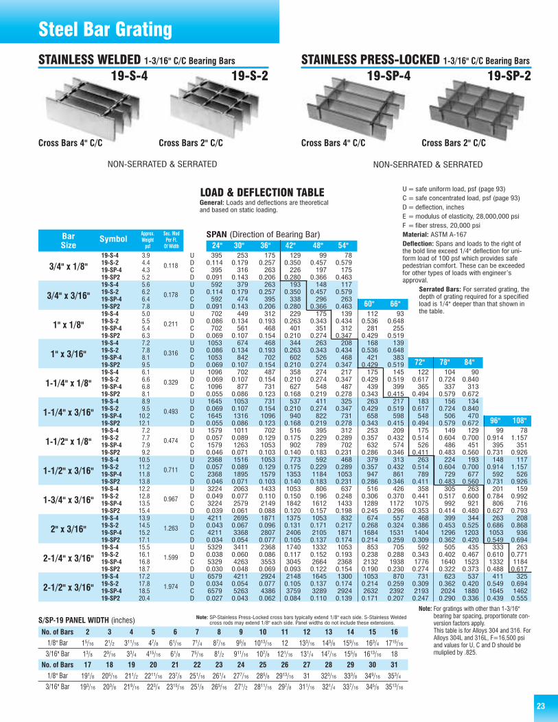
23
Steel Bar Grating
395 253 175 129 99 780.114 0.179 0.257 0.350 0.457 0.579395 316 263 226 197 175
0.091 0.143 0.206 0.280 0.366 0.463592 379 263 193 148 117
0.114 0.179 0.257 0.350 0.457 0.579592 474 395 338 296 263
0.091 0.143 0.206 0.280 0.366 0.463702 449 312 229 175 139 112 93
0.086 0.134 0.193 0.263 0.343 0.434 0.536 0.648702 561 468 401 351 312 281 255
0.069 0.107 0.154 0.210 0.274 0.347 0.429 0.5191053 674 468 344 263 208 168 1390.086 0.134 0.193 0.263 0.343 0.434 0.536 0.6481053 842 702 602 526 468 421 3830.069 0.107 0.154 0.210 0.274 0.347 0.429 0.5191096 702 487 358 274 217 175 145 122 104 900.069 0.107 0.154 0.210 0.274 0.347 0.429 0.519 0.617 0.724 0.8401096 877 731 627 548 487 439 399 365 337 3130.055 0.086 0.123 0.168 0.219 0.278 0.343 0.415 0.494 0.579 0.6721645 1053 731 537 411 325 263 217 183 156 1340.069 0.107 0.154 0.210 0.274 0.347 0.429 0.519 0.617 0.724 0.8401645 1316 1096 940 822 731 658 598 548 506 4700.055 0.086 0.123 0.168 0.219 0.278 0.343 0.415 0.494 0.579 0.6721579 1011 702 516 395 312 253 209 175 149 129 99 780.057 0.089 0.129 0.175 0.229 0.289 0.357 0.432 0.514 0.604 0.700 0.914 1.1571579 1263 1053 902 789 702 632 574 526 486 451 395 3510.046 0.071 0.103 0.140 0.183 0.231 0.286 0.346 0.411 0.483 0.560 0.731 0.9262368 1516 1053 773 592 468 379 313 263 224 193 148 1170.057 0.089 0.129 0.175 0.229 0.289 0.357 0.432 0.514 0.604 0.700 0.914 1.1572368 1895 1579 1353 1184 1053 947 861 789 729 677 592 5260.046 0.071 0.103 0.140 0.183 0.231 0.286 0.346 0.411 0.483 0.560 0.731 0.9263224 2063 1433 1053 806 637 516 426 358 305 263 201 1590.049 0.077 0.110 0.150 0.196 0.248 0.306 0.370 0.441 0.517 0.600 0.784 0.9923224 2579 2149 1842 1612 1433 1289 1172 1075 992 921 806 7160.039 0.061 0.088 0.120 0.157 0.198 0.245 0.296 0.353 0.414 0.480 0.627 0.7934211 2695 1871 1375 1053 832 674 557 468 399 344 263 2080.043 0.067 0.096 0.131 0.171 0.217 0.268 0.324 0.386 0.453 0.525 0.686 0.8684211 3368 2807 2406 2105 1871 1684 1531 1404 1296 1203 1053 9360.034 0.054 0.077 0.105 0.137 0.174 0.214 0.259 0.309 0.362 0.420 0.549 0.6945329 3411 2368 1740 1332 1053 853 705 592 505 435 333 2630.038 0.060 0.086 0.117 0.152 0.193 0.238 0.288 0.343 0.402 0.467 0.610 0.7715329 4263 3553 3045 2664 2368 2132 1938 1776 1640 1523 1332 11840.030 0.048 0.069 0.093 0.122 0.154 0.190 0.230 0.274 0.322 0.373 0.488 0.6176579 4211 2924 2148 1645 1300 1053 870 731 623 537 411 3250.034 0.054 0.077 0.105 0.137 0.174 0.214 0.259 0.309 0.362 0.420 0.549 0.6946579 5263 4386 3759 3289 2924 2632 2392 2193 2024 1880 1645 14620.027 0.043 0.062 0.084 0.110 0.139 0.171 0.207 0.247 0.290 0.336 0.439 0.555
19-S-419-S-219-SP-419-SP219-S-419-S-219-SP-419-SP219-S-419-S-219-SP-419-SP219-S-419-S-219-SP-419-SP219-S-419-S-219-SP-419-SP219-S-419-S-219-SP-419-SP219-S-419-S-219-SP-419-SP219-S-419-S-219-SP-419-SP219-S-419-S-219-SP-419-SP219-S-419-S-219-SP-419-SP219-S-419-S-219-SP-419-SP219-S-419-S-219-SP-419-SP2
96" 108"
72" 78" 84"
60" 66"
Approx. Sec. ModBar Symbol Weight Per Ft.Size psf Of Width
3/4" x 1/8"
3/4" x 3/16"
1" x 1/8"
1" x 3/16"
1-1/4" x 1/8"
1-1/4" x 3/16"
1-1/2" x 1/8"
1-1/2" x 3/16"
1-3/4" x 3/16"
2" x 3/16"
2-1/4" x 3/16"
2-1/2" x 3/16"
0.118
0.178
0.211
0.316
0.329
0.493
0.474
0.711
0.967
1.263
1.599
1.974
SPAN (Direction of Bearing Bar)
UDCDUDCDUDCDUDCDUDCDUDCDUDCDUDCDUDCDUDCDUDCDUDCD
U=safe uniform load, psf (page 93)C= safe concentrated load, psf (page 93)D=deflection, inchesE =modulus of elasticity, 28,000,000 psiF = fiber stress, 20,000 psiMaterial: ASTM A-167Deflection: Spans and loads to the right ofthe bold line exceed 1/4" deflection for uni-form load of 100 psf which provides safepedestrian comfort. These can be exceededfor other types of loads with engineer’sapproval.
Serrated Bars: For serrated grating, thedepth of grating required for a specifiedload is 1/4" deeper than that shown inthe table.
3.94.44.35.25.66.26.47.85.05.55.46.37.27.88.19.56.16.66.88.18.99.510.212.17.27.77.99.210.511.211.813.812.212.813.515.413.914.515.217.115.516.116.818.717.217.818.520.4
Cross Bars 4" C/C Cross Bars 2" C/C Cross Bars 2" C/CCross Bars 4" C/C
19-S-4 19-S-2 19-SP-219-SP-4
Note: For gratings with other than 1-3/16"bearing bar spacing, proportionate con-version factors apply.This table is for Alloys 304 and 316. ForAlloys 304L and 316L, F=16,500 psiand values for U, C and D should bemuliplied by .825.
24" 30" 36" 42" 48" 54"
S/SP-19 PANEL WIDTH (inches)No. of Bars 2 3 4 5 6 7 8 9 10 11 12 13 14 15 161/8" Bar
3/16" Bar15/16 21/2 311/16 47/8 61/16 71/4 87/16 95/8 1013/16 12 133/16 143/8 159/16 163/4 1715/16
13/8 29/16 33/4 415/16 61/8 75/16 81/2 911/16 107/8 121/16 131/4 147/16 155/8 1613/16 18
1/8" Bar
3/16" Bar191/8 205/16 211/2 2211/16 237/8 251/16 261/4 277/16 285/8 2913/16 31 323/16 333/8 349/16 353/4
193/16 203/8 219/16 223/4 2315/16 251/8 265/16 271/2 2811/16 297/8 311/16 321/4 337/16 345/8 3513/16
No. of Bars 17 18 19 20 21 22 23 24 25 26 27 28 29 30 31
Note: SP-Stainless Press-Locked cross bars typically extend 1/8" each side. S-Stainless Weldedcross rods may extend 1/8" each side. Panel widths do not include these extensions.
STAINLESS WELDED 1-3/16" C/C Bearing Bars STAINLESS PRESS-LOCKED 1-3/16" C/C Bearing Bars
NON-SERRATED & SERRATED NON-SERRATED & SERRATED
LOAD & DEFLECTION TABLEGeneral: Loads and deflections are theoreticaland based on static loading.
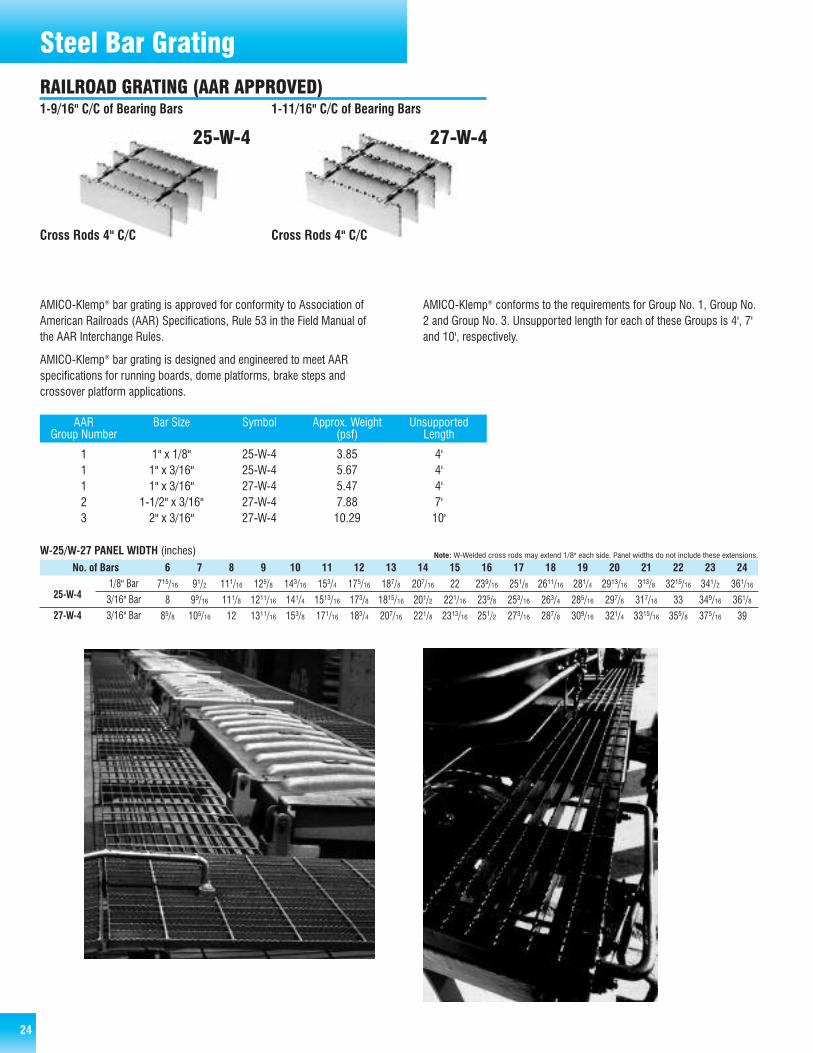
24
Steel Bar Grating
AMICO-Klemp® bar grating is approved for conformity to Association ofAmerican Railroads (AAR) Specifications, Rule 53 in the Field Manual ofthe AAR Interchange Rules.
AMICO-Klemp® bar grating is designed and engineered to meet AARspecifications for running boards, dome platforms, brake steps andcrossover platform applications.
AMICO-Klemp® conforms to the requirements for Group No. 1, Group No.2 and Group No. 3. Unsupported length for each of these Groups is 4', 7'and 10', respectively.
AAR Bar Size Symbol Approx. Weight UnsupportedGroup Number (psf) Length
1 1" x 1/8" 25-W-4 3.85 4'1 1" x 3/16" 25-W-4 5.67 4'1 1" x 3/16" 27-W-4 5.47 4'2 1-1/2" x 3/16" 27-W-4 7.88 7'3 2" x 3/16" 27-W-4 10.29 10'
6 7 8 9 10 11 12 13 14 15 16 17 18 19 20 21 22 23 24
715/16 91/2 111/16 125/8 143/16 153/4 175/16 187/8 207/16 22 239/16 251/8 2611/16 281/4 2913/16 313/8 3215/16 341/2 361/16
8 99/16 111/8 1211/16 141/4 1513/16 173/8 1815/16 201/2 221/16 235/8 253/16 263/4 285/16 297/8 317/16 33 349/16 361/8
85/8 105/16 12 1311/16 153/8 171/16 183/4 207/16 221/8 2313/16 251/2 273/16 287/8 309/16 321/4 3315/16 355/8 375/16 39
W-25/W-27 PANEL WIDTH (inches) Note: W-Welded cross rods may extend 1/8" each side. Panel widths do not include these extensions.
No. of Bars1/8" Bar
3/16" Bar
3/16" Bar
25-W-4
27-W-4
Cross Rods 4" C/CCross Rods 4" C/C
27-W-425-W-4
RAILROAD GRATING (AAR APPROVED)1-9/16" C/C of Bearing Bars 1-11/16" C/C of Bearing Bars

2525
Heavy-Duty Steel GratingHeavy-Duty Welded Grating has the strength for heavy-duty load areassuch as airfields, highways, industrial plants, truck and bus terminals,parking lots and railroad yards. Common uses are flooring, driveways,subway and tunnel ventilation grilles, curb inlet grates, ramps, docks, etc.
It is a sturdy grating to carry loads and maintain the same level overmany years of use. Whenever rolling wheel loads are to be used over thegrating, we recommend that the grating be load banded to add lateralstrength. Serrations are available on bars up to 3/8" thick to provideadditional traction for rolling loads.
Standard heavy-duty bar grating is resistance-welded for durability,strength and safety using an automated electric/hydraulic weldingprocess. High temperatures, combined with high pressure, fuse thebearing bars and cross bars together to form a permanent joint.
Also, AMICO-Klemp® is one of the few manufacturers that has thecapability of providing you with those “really big” grates. Our heavy-dutyfabrication department regularly custom fabricates grating to meet spe-cific project requirements. Virtually any bar size and depth can be madeto order.
15-H-4 15-H-2
19-H-4 19-H-2
22-H-4 22-H-2
30-H-4 30-H-2
38-H-4 38-H-2
HEAVY-DUTY WELDED STEEL BAR GRATING
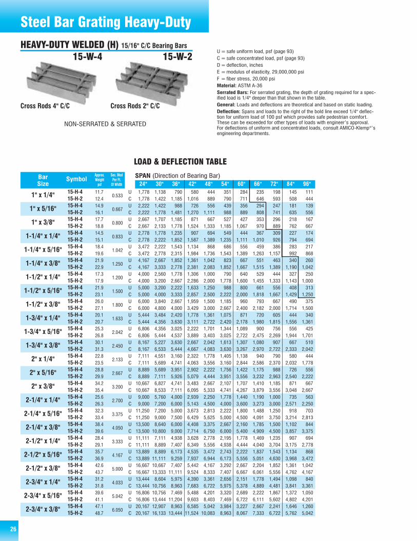
26
1,778 1,138 790 580 444 351 284 235 198 145 1111,778 1,422 1,185 1,016 889 790 711 646 593 508 4442,222 1,422 988 726 556 439 356 294 247 181 1392,222 1,778 1,481 1,270 1,111 988 889 808 741 635 5562,667 1,707 1,185 871 667 527 427 353 296 218 1672,667 2,133 1,778 1,524 1,333 1,185 1,067 970 889 762 6672,778 1,778 1,235 907 694 549 444 367 309 227 1742,778 2,222 1,852 1,587 1,389 1,235 1,111 1,010 926 794 6943,472 2,222 1,543 1,134 868 686 556 459 386 283 2173,472 2,778 2,315 1,984 1,736 1,543 1,389 1,263 1,157 992 8684,167 2,667 1,852 1,361 1,042 823 667 551 463 340 2604,167 3,333 2,778 2,381 2,083 1,852 1,667 1,515 1,389 1,190 1,0424,000 2,560 1,778 1,306 1,000 790 640 529 444 327 2504,000 3,200 2,667 2,286 2,000 1,778 1,600 1,455 1,333 1,143 1,0005,000 3,200 2,222 1,633 1,250 988 800 661 556 408 3135,000 4,000 3,333 2,857 2,500 2,222 2,000 1,818 1,667 1,429 1,2506,000 3,840 2,667 1,959 1,500 1,185 960 793 667 490 3756,000 4,800 4,000 3,429 3,000 2,667 2,400 2,182 2,000 1,714 1,5005,444 3,484 2,420 1,778 1,361 1,075 871 720 605 444 3405,444 4,356 3,630 3,111 2,722 2,420 2,178 1,980 1,815 1,556 1,3616,806 4,356 3,025 2,222 1,701 1,344 1,089 900 756 556 4256,806 5,444 4,537 3,889 3,403 3,025 2,722 2,475 2,269 1,944 1,7018,167 5,227 3,630 2,667 2,042 1,613 1,307 1,080 907 667 5108,167 6,533 5,444 4,667 4,083 3,630 3,267 2,970 2,722 2,333 2,0427,111 4,551 3,160 2,322 1,778 1,405 1,138 940 790 580 4447,111 5,689 4,741 4,063 3,556 3,160 2,844 2,586 2,370 2,032 1,7788,889 5,689 3,951 2,902 2,222 1,756 1,422 1,175 988 726 5568,889 7,111 5,926 5,079 4,444 3,951 3,556 3,232 2,963 2,540 2,22210,667 6,827 4,741 3,483 2,667 2,107 1,707 1,410 1,185 871 66710,667 8,533 7,111 6,095 5,333 4,741 4,267 3,879 3,556 3,048 2,6679,000 5,760 4,000 2,939 2,250 1,778 1,440 1,190 1,000 735 5639,000 7,200 6,000 5,143 4,500 4,000 3,600 3,273 3,000 2,571 2,25011,250 7,200 5,000 3,673 2,813 2,222 1,800 1,488 1,250 918 70311,250 9,000 7,500 6,429 5,625 5,000 4,500 4,091 3,750 3,214 2,81313,500 8,640 6,000 4,408 3,375 2,667 2,160 1,785 1,500 1,102 84413,500 10,800 9,000 7,714 6,750 6,000 5,400 4,909 4,500 3,857 3,37511,111 7,111 4,938 3,628 2,778 2,195 1,778 1,469 1,235 907 69411,111 8,889 7,407 6,349 5,556 4,938 4,444 4,040 3,704 3,175 2,77813,889 8,889 6,173 4,535 3,472 2,743 2,222 1,837 1,543 1,134 86813,889 11,111 9,259 7,937 6,944 6,173 5,556 5,051 4,630 3,968 3,47216,667 10,667 7,407 5,442 4,167 3,292 2,667 2,204 1,852 1,361 1,04216,667 13,333 11,111 9,524 8,333 7,407 6,667 6,061 5,556 4,762 4,16713,444 8,604 5,975 4,390 3,361 2,656 2,151 1,778 1,494 1,098 84013,444 10,756 8,963 7,683 6,722 5,975 5,378 4,889 4,481 3,841 3,36116,806 10,756 7,469 5,488 4,201 3,320 2,689 2,222 1,867 1,372 1,05016,806 13,444 11,204 9,603 8,403 7,469 6,722 6,111 5,602 4,802 4,20120,167 12,907 8,963 6,585 5,042 3,984 3,227 2,667 2,241 1,646 1,26020,167 16,133 13,444 11,524 10,083 8,963 8,067 7,333 6,722 5,762 5,042
15-H-415-H-215-H-415-H-215-H-415-H-215-H-415-H-215-H-415-H-215-H-415-H-215-H-415-H-215-H-415-H-215-H-415-H-215-H-415-H-215-H-415-H-215-H-415-H-215-H-415-H-215-H-415-H-215-H-415-H-215-H-415-H-215-H-415-H-215-H-415-H-215-H-415-H-215-H-415-H-215-H-415-H-215-H-415-H-215-H-415-H-215-H-415-H-2
24" 30" 36" 42" 48" 54" 60" 66" 72" 84" 96"
Approx. Sec. ModBar Symbol Weight Per Ft.Size psf Of Width
1" x 1/4"
1" x 5/16"
1" x 3/8"
1-1/4" x 1/4"
1-1/4" x 5/16"
1-1/4" x 3/8"
1-1/2" x 1/4"
1-1/2" x 5/16"
1-1/2" x 3/8"
1-3/4" x 1/4"
1-3/4" x 5/16"
1-3/4" x 3/8"
2" x 1/4"
2" x 5/16"
2" x 3/8"
2-1/4" x 1/4"
2-1/4" x 5/16"
2-1/4" x 3/8"
2-1/2" x 1/4"
2-1/2" x 5/16"
2-1/2" x 3/8"
2-3/4" x 1/4"
2-3/4" x 5/16"
2-3/4" x 3/8"
0.533
0.667
0.800
0.833
1.042
1.250
1.200
1.500
1.800
1.633
2.042
2.450
2.133
2.667
3.200
2.700
3.375
4.050
3.333
4.167
5.000
4.033
5.042
6.050
SPAN (Direction of Bearing Bar)
LOAD & DEFLECTION TABLE
UCUCUCUCUCUCUCUCUCUCUCUCUCUCUCUCUCUCUCUCUCUCUCUC
11.712.414.916.117.718.814.515.118.419.621.922.917.317.921.923.126.027.120.120.725.326.830.131.322.823.528.829.934.235.425.626.332.333.438.439.628.429.135.736.942.643.731.231.839.641.147.148.7
Steel Bar Grating Heavy-Duty
Cross Rods 4" C/C Cross Rods 2" C/C
15-W-4 15-W-2U=safe uniform load, psf (page 93)C= safe concentrated load, psf (page 93)D=deflection, inchesE =modulus of elasticity, 29,000,000 psiF = fiber stress, 20,000 psiMaterial: ASTM A-36Serrated Bars: For serrated grating, the depth of grating required for a spec-ified load is 1/4" deeper than that shown in the table.General: Loads and deflections are theoretical and based on static loading.Deflection: Spans and loads to the right of the bold line exceed 1/4" deflec-tion for uniform load of 100 psf which provides safe pedestrian comfort.These can be exceeded for other types of loads with engineer’s approval.For deflections of uniform and concentrated loads, consult AMICO-Klemp®’sengineering departments.
HEAVY-DUTY WELDED (H) 15/16" C/C Bearing Bars
NON-SERRATED & SERRATED

27
16,000 10,240 7,111 5,224 4,000 3,160 2,560 2,116 1,778 1,306 1,00016,000 12,800 10,667 9,143 8,000 7,111 6,400 5,818 5,333 4,571 4,00020,000 12,800 8,889 6,531 5,000 3,951 3,200 2,645 2,222 1,633 1,25020,000 16,000 13,333 11,429 10,000 8,889 8,000 7,273 6,667 5,714 5,00024,000 15,360 10,667 7,837 6,000 4,741 3,840 3,174 2,667 1,959 1,50024,000 19,200 16,000 13,714 12,000 10,667 9,600 8,727 8,000 6,857 6,00018,778 12,018 8,346 6,132 4,694 3,709 3,004 2,483 2,086 1,533 1,17418,778 15,022 12,519 10,730 9,389 8,346 7,511 6,828 6,259 5,365 4,69423,472 15,022 10,432 7,664 5,868 4,636 3,756 3,104 2,608 1,916 1,46723,472 18,778 15,648 13,413 11,736 10,432 9,389 8,535 7,824 6,706 5,86828,167 18,027 12,519 9,197 7,042 5,564 4,507 3,725 3,130 2,299 1,76028,167 22,533 18,778 16,095 14,083 12,519 11,267 10,242 9,389 8,048 7,04221,778 13,938 9,679 7,111 5,444 4,302 3,484 2,880 2,420 1,778 1,36121,778 17,422 14,519 12,444 10,889 9,679 8,711 7,919 7,259 6,222 5,44427,222 17,422 12,099 8,889 6,806 5,377 4,356 3,600 3,025 2,222 1,70127,222 21,778 18,148 15,556 13,611 12,099 10,889 9,899 9,074 7,778 6,80632,667 20,907 14,519 10,667 8,167 6,453 5,227 4,320 3,630 2,667 2,04232,667 26,133 21,778 18,667 16,333 14,519 13,067 11,879 10,889 9,333 8,16728,444 18,204 12,642 9,288 7,111 5,619 4,551 3,761 3,160 2,322 1,77828,444 22,756 18,963 16,254 14,222 12,642 11,378 10,343 9,481 8,127 7,11135,556 22,756 15,802 11,610 8,889 7,023 5,689 4,702 3,951 2,902 2,22235,556 28,444 23,704 20,317 17,778 15,802 14,222 12,929 11,852 10,159 8,88942,667 27,307 18,963 13,932 10,667 8,428 6,827 5,642 4,741 3,483 2,66742,667 34,133 28,444 24,381 21,333 18,963 17,067 15,515 14,222 12,190 10,66736,000 23,040 16,000 11,755 9,000 7,111 5,760 4,760 4,000 2,939 2,25036,000 28,800 24,000 20,571 18,000 16,000 14,400 13,091 12,000 10,286 9,00045,000 28,800 20,000 14,694 11,250 8,889 7,200 5,950 5,000 3,673 2,81345,000 36,000 30,000 25,714 22,500 20,000 18,000 16,364 15,000 12,857 11,25054,000 34,560 24,000 17,633 13,500 10,667 8,640 7,140 6,000 4,408 3,37554,000 43,200 36,000 30,857 27,000 24,000 21,600 19,636 18,000 15,429 13,50044,444 28,444 19,753 14,512 11,111 8,779 7,111 5,877 4,938 3,628 2,77844,444 35,556 29,630 25,397 22,222 19,753 17,778 16,162 14,815 12,698 11,11155,556 35,556 24,691 18,141 13,889 10,974 8,889 7,346 6,173 4,535 3,47255,556 44,444 37,037 31,746 27,778 24,691 22,222 20,202 18,519 15,873 13,88966,667 42,667 29,630 21,769 16,667 13,169 10,667 8,815 7,407 5,442 4,16766,667 53,333 44,444 38,095 33,333 29,630 26,667 24,242 22,222 19,048 16,66764,000 40,960 28,444 20,898 16,000 12,642 10,240 8,463 7,111 5,224 4,00064,000 51,200 42,667 36,571 32,000 28,444 25,600 23,273 21,333 18,286 16,00080,000 51,200 35,556 26,122 20,000 15,802 12,800 10,579 8,889 6,531 5,00080,000 64,000 53,333 45,714 40,000 35,556 32,000 29,091 26,667 22,857 20,00096,000 61,440 42,667 31,347 24,000 18,963 15,360 12,694 10,667 7,837 6,00096,000 76,800 64,000 54,857 48,000 42,667 38,400 34,909 32,000 27,429 24,000
15-H-415-H-215-H-415-H-215-H-415-H-215-H-415-H-215-H-415-H-215-H-415-H-215-H-415-H-215-H-415-H-215-H-415-H-215-H-415-H-215-H-415-H-215-H-415-H-215-H-415-H-215-H-415-H-215-H-415-H-215-H-415-H-215-H-415-H-215-H-415-H-215-H-415-H-215-H-415-H-215-H-415-H-2
24" 30" 36" 42" 48" 54" 60" 66" 72" 84" 96"
Approx. Sec. ModBar Symbol Weight Per Ft.Size psf Of Width
3" x 1/4"
3" x 5/16"
3" x 3/8"
3-1/4" x 1/4"
3-1/4" x 5/16"
3-1/4" x 3/8"
3-1/2" x 1/4"
3-1/2" x 5/16"
3-1/2" x 3/8"
4" x 1/4"
4" x 5/16"
4" x 3/8"
4-1/2" x 1/4"
4-1/2" x 5/16"
4-1/2" x 3/8"
5" x 1/4"
5" x 5/16"
5" x 3/8"
6" x 1/4"
6" x 5/16"
6" x 3/8"
4.800
6.000
7.200
5.633
7.042
8.450
6.533
8.167
9.800
8.533
10.667
12.800
10.800
13.500
16.200
13.333
16.667
20.000
19.200
24.000
28.800
SPAN (Direction of Bearing Bar)
LOAD & DEFLECTION TABLE
UCUCUCUCUCUCUCUCUCUCUCUCUCUCUCUCUCUCUCUCUC
34.435.543.144.651.352.837.238.346.548.155.456.939.941.149.951.559.561.145.546.656.958.467.869.451.152.263.865.376.177.756.657.770.772.384.485.967.768.884.686.1100.9102.5
Steel Bar Grating Heavy-Duty
2 3 4 5 6 7 8 9 10 11 12 13 14 15 16 17 18 19 20
1/4" Bar
5/16" Bar
3/8" Bar
13/16 21/8 31/16 4 415/16 57/8 613/16 73/4 811/16 95/8 109/16 111/2 127/16 133/8 145/16 151/4 163/16 171/8 181/16
11/4 23/16 31/8 41/16 5 515/16 67/8 713/16 83/4 911/16 105/8 119/16 121/2 137/16 143/8 155/16 161/4 173/16 181/8
15/16 21/4 33/16 41/8 51/16 6 615/16 77/8 813/16 93/4 1011/16 115/8 129/16 131/2 147/16 153/8 165/16 171/4 183/16
No. of Bars
21 22 23 24 25 26 27 28 29 30 31 32 33 34 35 36 37 38 39
1/4" Bar
5/16" Bar
3/8" Bar
19 1915/16 207/8 2113/16 223/4 2311/16 245/8 259/16 261/2 277/16 283/8 295/16 301/4 313/16 321/8 331/16 34 3415/16 357/8
191/16 20 2015/16 217/8 2213/16 233/4 2411/16 255/8 269/16 271/2 287/16 293/8 305/16 311/4 323/16 331/8 341/16 35 3515/16
191/8 201/16 21 2115/16 227/8 2313/16 243/4 2511/16 265/8 279/16 281/2 297/16 303/8 315/16 321/4 333/16 341/8 351/16 36
No. of Bars
H-15 PANEL WIDTH (inches) Note: H-Heavy Duty cross rods may extend 1/8" each side. Panel widths do not include these extensions.
15-H-4 & 15-H-2 (continued)
All 1/4" Bar Size Can Go Up To 39 Bars Wide1 x 5/16 thru 2-1/2 x 3/8 Up To 39 Bars Wide2-3/4 x 5/16 Thru 6 x 3/8 Up To 26 Bars Wide
NON-SERRATED & SERRATED
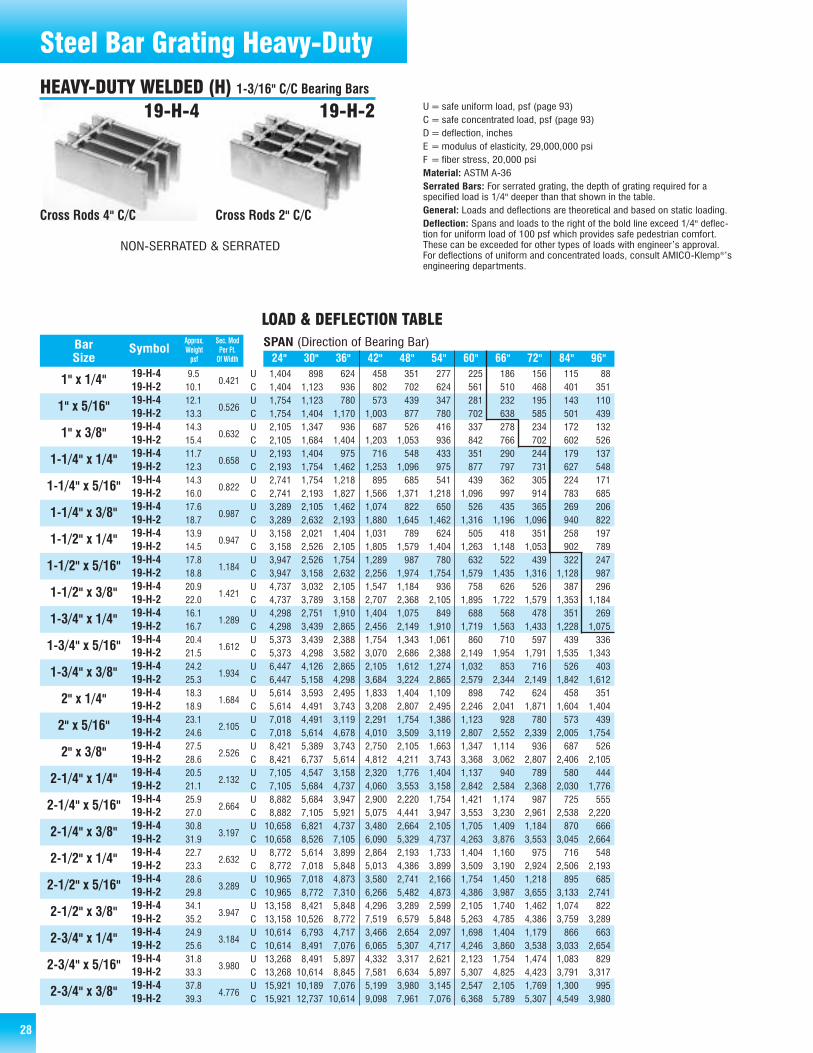
28
1,404 898 624 458 351 277 225 186 156 115 881,404 1,123 936 802 702 624 561 510 468 401 3511,754 1,123 780 573 439 347 281 232 195 143 1101,754 1,404 1,170 1,003 877 780 702 638 585 501 4392,105 1,347 936 687 526 416 337 278 234 172 1322,105 1,684 1,404 1,203 1,053 936 842 766 702 602 5262,193 1,404 975 716 548 433 351 290 244 179 1372,193 1,754 1,462 1,253 1,096 975 877 797 731 627 5482,741 1,754 1,218 895 685 541 439 362 305 224 1712,741 2,193 1,827 1,566 1,371 1,218 1,096 997 914 783 6853,289 2,105 1,462 1,074 822 650 526 435 365 269 2063,289 2,632 2,193 1,880 1,645 1,462 1,316 1,196 1,096 940 8223,158 2,021 1,404 1,031 789 624 505 418 351 258 1973,158 2,526 2,105 1,805 1,579 1,404 1,263 1,148 1,053 902 7893,947 2,526 1,754 1,289 987 780 632 522 439 322 2473,947 3,158 2,632 2,256 1,974 1,754 1,579 1,435 1,316 1,128 9874,737 3,032 2,105 1,547 1,184 936 758 626 526 387 2964,737 3,789 3,158 2,707 2,368 2,105 1,895 1,722 1,579 1,353 1,1844,298 2,751 1,910 1,404 1,075 849 688 568 478 351 2694,298 3,439 2,865 2,456 2,149 1,910 1,719 1,563 1,433 1,228 1,0755,373 3,439 2,388 1,754 1,343 1,061 860 710 597 439 3365,373 4,298 3,582 3,070 2,686 2,388 2,149 1,954 1,791 1,535 1,3436,447 4,126 2,865 2,105 1,612 1,274 1,032 853 716 526 4036,447 5,158 4,298 3,684 3,224 2,865 2,579 2,344 2,149 1,842 1,6125,614 3,593 2,495 1,833 1,404 1,109 898 742 624 458 3515,614 4,491 3,743 3,208 2,807 2,495 2,246 2,041 1,871 1,604 1,4047,018 4,491 3,119 2,291 1,754 1,386 1,123 928 780 573 4397,018 5,614 4,678 4,010 3,509 3,119 2,807 2,552 2,339 2,005 1,7548,421 5,389 3,743 2,750 2,105 1,663 1,347 1,114 936 687 5268,421 6,737 5,614 4,812 4,211 3,743 3,368 3,062 2,807 2,406 2,1057,105 4,547 3,158 2,320 1,776 1,404 1,137 940 789 580 4447,105 5,684 4,737 4,060 3,553 3,158 2,842 2,584 2,368 2,030 1,7768,882 5,684 3,947 2,900 2,220 1,754 1,421 1,174 987 725 5558,882 7,105 5,921 5,075 4,441 3,947 3,553 3,230 2,961 2,538 2,22010,658 6,821 4,737 3,480 2,664 2,105 1,705 1,409 1,184 870 66610,658 8,526 7,105 6,090 5,329 4,737 4,263 3,876 3,553 3,045 2,6648,772 5,614 3,899 2,864 2,193 1,733 1,404 1,160 975 716 5488,772 7,018 5,848 5,013 4,386 3,899 3,509 3,190 2,924 2,506 2,19310,965 7,018 4,873 3,580 2,741 2,166 1,754 1,450 1,218 895 68510,965 8,772 7,310 6,266 5,482 4,873 4,386 3,987 3,655 3,133 2,74113,158 8,421 5,848 4,296 3,289 2,599 2,105 1,740 1,462 1,074 82213,158 10,526 8,772 7,519 6,579 5,848 5,263 4,785 4,386 3,759 3,28910,614 6,793 4,717 3,466 2,654 2,097 1,698 1,404 1,179 866 66310,614 8,491 7,076 6,065 5,307 4,717 4,246 3,860 3,538 3,033 2,65413,268 8,491 5,897 4,332 3,317 2,621 2,123 1,754 1,474 1,083 82913,268 10,614 8,845 7,581 6,634 5,897 5,307 4,825 4,423 3,791 3,31715,921 10,189 7,076 5,199 3,980 3,145 2,547 2,105 1,769 1,300 99515,921 12,737 10,614 9,098 7,961 7,076 6,368 5,789 5,307 4,549 3,980
19-H-419-H-219-H-419-H-219-H-419-H-219-H-419-H-219-H-419-H-219-H-419-H-219-H-419-H-219-H-419-H-219-H-419-H-219-H-419-H-219-H-419-H-219-H-419-H-219-H-419-H-219-H-419-H-219-H-419-H-219-H-419-H-219-H-419-H-219-H-419-H-219-H-419-H-219-H-419-H-219-H-419-H-219-H-419-H-219-H-419-H-219-H-419-H-2
24" 30" 36" 42" 48" 54" 60" 66" 72" 84" 96"
Approx. Sec. ModBar Symbol Weight Per Ft.Size psf Of Width
1" x 1/4"
1" x 5/16"
1" x 3/8"
1-1/4" x 1/4"
1-1/4" x 5/16"
1-1/4" x 3/8"
1-1/2" x 1/4"
1-1/2" x 5/16"
1-1/2" x 3/8"
1-3/4" x 1/4"
1-3/4" x 5/16"
1-3/4" x 3/8"
2" x 1/4"
2" x 5/16"
2" x 3/8"
2-1/4" x 1/4"
2-1/4" x 5/16"
2-1/4" x 3/8"
2-1/2" x 1/4"
2-1/2" x 5/16"
2-1/2" x 3/8"
2-3/4" x 1/4"
2-3/4" x 5/16"
2-3/4" x 3/8"
0.421
0.526
0.632
0.658
0.822
0.987
0.947
1.184
1.421
1.289
1.612
1.934
1.684
2.105
2.526
2.132
2.664
3.197
2.632
3.289
3.947
3.184
3.980
4.776
SPAN (Direction of Bearing Bar)
LOAD & DEFLECTION TABLE
UCUCUCUCUCUCUCUCUCUCUCUCUCUCUCUCUCUCUCUCUCUCUCUC
9.510.112.113.314.315.411.712.314.316.017.618.713.914.517.818.820.922.016.116.720.421.524.225.318.318.923.124.627.528.620.521.125.927.030.831.922.723.328.629.834.135.224.925.631.833.337.839.3
Cross Rods 4" C/C Cross Rods 2" C/C
19-H-4 19-H-2 U=safe uniform load, psf (page 93)C= safe concentrated load, psf (page 93)D=deflection, inchesE =modulus of elasticity, 29,000,000 psiF = fiber stress, 20,000 psiMaterial: ASTM A-36Serrated Bars: For serrated grating, the depth of grating required for aspecified load is 1/4" deeper than that shown in the table.General: Loads and deflections are theoretical and based on static loading.Deflection: Spans and loads to the right of the bold line exceed 1/4" deflec-tion for uniform load of 100 psf which provides safe pedestrian comfort.These can be exceeded for other types of loads with engineer’s approval.For deflections of uniform and concentrated loads, consult AMICO-Klemp®’sengineering departments.
Steel Bar Grating Heavy-DutyHEAVY-DUTY WELDED (H) 1-3/16" C/C Bearing Bars
NON-SERRATED & SERRATED
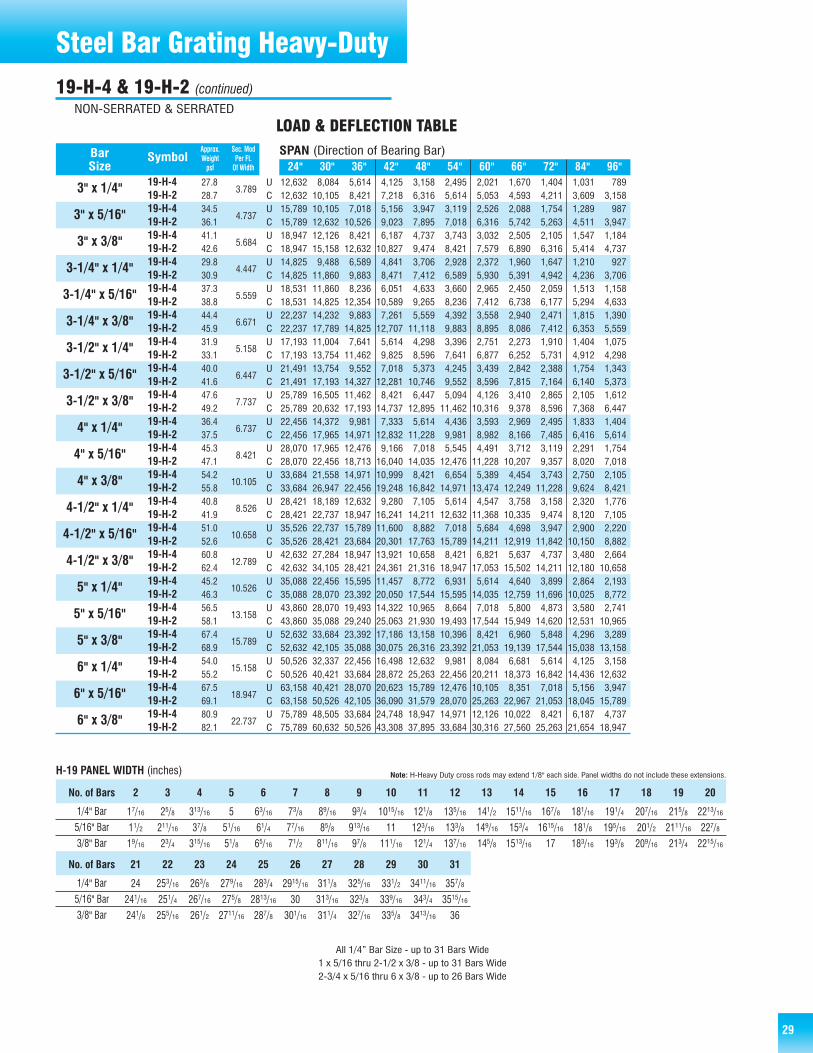
29
12,632 8,084 5,614 4,125 3,158 2,495 2,021 1,670 1,404 1,031 78912,632 10,105 8,421 7,218 6,316 5,614 5,053 4,593 4,211 3,609 3,15815,789 10,105 7,018 5,156 3,947 3,119 2,526 2,088 1,754 1,289 98715,789 12,632 10,526 9,023 7,895 7,018 6,316 5,742 5,263 4,511 3,94718,947 12,126 8,421 6,187 4,737 3,743 3,032 2,505 2,105 1,547 1,18418,947 15,158 12,632 10,827 9,474 8,421 7,579 6,890 6,316 5,414 4,73714,825 9,488 6,589 4,841 3,706 2,928 2,372 1,960 1,647 1,210 92714,825 11,860 9,883 8,471 7,412 6,589 5,930 5,391 4,942 4,236 3,70618,531 11,860 8,236 6,051 4,633 3,660 2,965 2,450 2,059 1,513 1,15818,531 14,825 12,354 10,589 9,265 8,236 7,412 6,738 6,177 5,294 4,63322,237 14,232 9,883 7,261 5,559 4,392 3,558 2,940 2,471 1,815 1,39022,237 17,789 14,825 12,707 11,118 9,883 8,895 8,086 7,412 6,353 5,55917,193 11,004 7,641 5,614 4,298 3,396 2,751 2,273 1,910 1,404 1,07517,193 13,754 11,462 9,825 8,596 7,641 6,877 6,252 5,731 4,912 4,29821,491 13,754 9,552 7,018 5,373 4,245 3,439 2,842 2,388 1,754 1,34321,491 17,193 14,327 12,281 10,746 9,552 8,596 7,815 7,164 6,140 5,37325,789 16,505 11,462 8,421 6,447 5,094 4,126 3,410 2,865 2,105 1,61225,789 20,632 17,193 14,737 12,895 11,462 10,316 9,378 8,596 7,368 6,44722,456 14,372 9,981 7,333 5,614 4,436 3,593 2,969 2,495 1,833 1,40422,456 17,965 14,971 12,832 11,228 9,981 8,982 8,166 7,485 6,416 5,61428,070 17,965 12,476 9,166 7,018 5,545 4,491 3,712 3,119 2,291 1,75428,070 22,456 18,713 16,040 14,035 12,476 11,228 10,207 9,357 8,020 7,01833,684 21,558 14,971 10,999 8,421 6,654 5,389 4,454 3,743 2,750 2,10533,684 26,947 22,456 19,248 16,842 14,971 13,474 12,249 11,228 9,624 8,42128,421 18,189 12,632 9,280 7,105 5,614 4,547 3,758 3,158 2,320 1,77628,421 22,737 18,947 16,241 14,211 12,632 11,368 10,335 9,474 8,120 7,10535,526 22,737 15,789 11,600 8,882 7,018 5,684 4,698 3,947 2,900 2,22035,526 28,421 23,684 20,301 17,763 15,789 14,211 12,919 11,842 10,150 8,88242,632 27,284 18,947 13,921 10,658 8,421 6,821 5,637 4,737 3,480 2,66442,632 34,105 28,421 24,361 21,316 18,947 17,053 15,502 14,211 12,180 10,65835,088 22,456 15,595 11,457 8,772 6,931 5,614 4,640 3,899 2,864 2,19335,088 28,070 23,392 20,050 17,544 15,595 14,035 12,759 11,696 10,025 8,77243,860 28,070 19,493 14,322 10,965 8,664 7,018 5,800 4,873 3,580 2,74143,860 35,088 29,240 25,063 21,930 19,493 17,544 15,949 14,620 12,531 10,96552,632 33,684 23,392 17,186 13,158 10,396 8,421 6,960 5,848 4,296 3,28952,632 42,105 35,088 30,075 26,316 23,392 21,053 19,139 17,544 15,038 13,15850,526 32,337 22,456 16,498 12,632 9,981 8,084 6,681 5,614 4,125 3,15850,526 40,421 33,684 28,872 25,263 22,456 20,211 18,373 16,842 14,436 12,63263,158 40,421 28,070 20,623 15,789 12,476 10,105 8,351 7,018 5,156 3,94763,158 50,526 42,105 36,090 31,579 28,070 25,263 22,967 21,053 18,045 15,78975,789 48,505 33,684 24,748 18,947 14,971 12,126 10,022 8,421 6,187 4,73775,789 60,632 50,526 43,308 37,895 33,684 30,316 27,560 25,263 21,654 18,947
19-H-419-H-219-H-419-H-219-H-419-H-219-H-419-H-219-H-419-H-219-H-419-H-219-H-419-H-219-H-419-H-219-H-419-H-219-H-419-H-219-H-419-H-219-H-419-H-219-H-419-H-219-H-419-H-219-H-419-H-219-H-419-H-219-H-419-H-219-H-419-H-219-H-419-H-219-H-419-H-219-H-419-H-2
24" 30" 36" 42" 48" 54" 60" 66" 72" 84" 96"
Approx. Sec. ModBar Symbol Weight Per Ft.Size psf Of Width
3" x 1/4"
3" x 5/16"
3" x 3/8"
3-1/4" x 1/4"
3-1/4" x 5/16"
3-1/4" x 3/8"
3-1/2" x 1/4"
3-1/2" x 5/16"
3-1/2" x 3/8"
4" x 1/4"
4" x 5/16"
4" x 3/8"
4-1/2" x 1/4"
4-1/2" x 5/16"
4-1/2" x 3/8"
5" x 1/4"
5" x 5/16"
5" x 3/8"
6" x 1/4"
6" x 5/16"
6" x 3/8"
3.789
4.737
5.684
4.447
5.559
6.671
5.158
6.447
7.737
6.737
8.421
10.105
8.526
10.658
12.789
10.526
13.158
15.789
15.158
18.947
22.737
SPAN (Direction of Bearing Bar)
LOAD & DEFLECTION TABLE
UCUCUCUCUCUCUCUCUCUCUCUCUCUCUCUCUCUCUCUCUC
27.828.734.536.141.142.629.830.937.338.844.445.931.933.140.041.647.649.236.437.545.347.154.255.840.841.951.052.660.862.445.246.356.558.167.468.954.055.267.569.180.982.1
2 3 4 5 6 7 8 9 10 11 12 13 14 15 16 17 18 19 20
1/4" Bar
5/16" Bar
3/8" Bar
17/16 25/8 313/16 5 63/16 73/8 89/16 93/4 1015/16 121/8 135/16 141/2 1511/16 167/8 181/16 191/4 207/16 215/8 2213/16
11/2 211/16 37/8 51/16 61/4 77/16 85/8 913/16 11 123/16 133/8 149/16 153/4 1615/16 181/8 195/16 201/2 2111/16 227/8
19/16 23/4 315/16 51/8 65/16 71/2 811/16 97/8 111/16 121/4 137/16 145/8 1513/16 17 183/16 193/8 209/16 213/4 2215/16
No. of Bars
21 22 23 24 25 26 27 28 29 30 31
1/4" Bar
5/16" Bar
3/8" Bar
24 253/16 263/8 279/16 283/4 2915/16 311/8 325/16 331/2 3411/16 357/8
241/16 251/4 267/16 275/8 2813/16 30 313/16 323/8 339/16 343/4 3515/16
241/8 255/16 261/2 2711/16 287/8 301/16 311/4 327/16 335/8 3413/16 36
No. of Bars
H-19 PANEL WIDTH (inches) Note: H-Heavy Duty cross rods may extend 1/8" each side. Panel widths do not include these extensions.
Steel Bar Grating Heavy-Duty19-H-4 & 19-H-2 (continued)
All 1/4” Bar Size - up to 31 Bars Wide1 x 5/16 thru 2-1/2 x 3/8 - up to 31 Bars Wide2-3/4 x 5/16 thru 6 x 3/8 - up to 26 Bars Wide
NON-SERRATED & SERRATED

30
1,212 776 539 396 303 239 194 160 135 99 761,212 970 808 693 606 539 485 441 404 346 3031,515 970 673 495 379 299 242 200 168 124 951,515 1,212 1,010 866 758 673 606 551 505 433 3791,818 1,164 808 594 455 359 291 240 202 148 1141,818 1,455 1,212 1,039 909 808 727 661 606 519 4551,894 1,212 842 618 473 374 303 250 210 155 1181,894 1,515 1,263 1,082 947 842 758 689 631 541 4732,367 1,515 1,052 773 592 468 379 313 263 193 1482,367 1,894 1,578 1,353 1,184 1,052 947 861 789 676 5922,841 1,818 1,263 928 710 561 455 376 316 232 1782,841 2,273 1,894 1,623 1,420 1,263 1,136 1,033 947 812 7102,727 1,745 1,212 891 682 539 436 361 303 223 1702,727 2,182 1,818 1,558 1,364 1,212 1,091 992 909 779 6823,409 2,182 1,515 1,113 852 673 545 451 379 278 2133,409 2,727 2,273 1,948 1,705 1,515 1,364 1,240 1,136 974 8524,091 2,618 1,818 1,336 1,023 808 655 541 455 334 2564,091 3,273 2,727 2,338 2,045 1,818 1,636 1,488 1,364 1,169 1,0233,712 2,376 1,650 1,212 928 733 594 491 412 303 2323,712 2,970 2,475 2,121 1,856 1,650 1,485 1,350 1,237 1,061 9284,640 2,970 2,062 1,515 1,160 917 742 614 516 379 2904,640 3,712 3,093 2,652 2,320 2,062 1,856 1,687 1,547 1,326 1,1605,568 3,564 2,475 1,818 1,392 1,100 891 736 619 455 3485,568 4,455 3,712 3,182 2,784 2,475 2,227 2,025 1,856 1,591 1,3924,848 3,103 2,155 1,583 1,212 958 776 641 539 396 3034,848 3,879 3,232 2,771 2,424 2,155 1,939 1,763 1,616 1,385 1,2126,061 3,879 2,694 1,979 1,515 1,197 970 801 673 495 3796,061 4,848 4,040 3,463 3,030 2,694 2,424 2,204 2,020 1,732 1,5157,273 4,655 3,232 2,375 1,818 1,437 1,164 962 808 594 4557,273 5,818 4,848 4,156 3,636 3,232 2,909 2,645 2,424 2,078 1,8186,136 3,927 2,727 2,004 1,534 1,212 982 811 682 501 3846,136 4,909 4,091 3,506 3,068 2,727 2,455 2,231 2,045 1,753 1,5347,670 4,909 3,409 2,505 1,918 1,515 1,227 1,014 852 626 4797,670 6,136 5,114 4,383 3,835 3,409 3,068 2,789 2,557 2,192 1,9189,205 5,891 4,091 3,006 2,301 1,818 1,473 1,217 1,023 751 5759,205 7,364 6,136 5,260 4,602 4,091 3,682 3,347 3,068 2,630 2,3017,576 4,848 3,367 2,474 1,894 1,496 1,212 1,002 842 618 4737,576 6,061 5,051 4,329 3,788 3,367 3,030 2,755 2,525 2,165 1,8949,470 6,061 4,209 3,092 2,367 1,871 1,515 1,252 1,052 773 5929,470 7,576 6,313 5,411 4,735 4,209 3,788 3,444 3,157 2,706 2,36711,364 7,273 5,051 3,711 2,841 2,245 1,818 1,503 1,263 928 71011,364 9,091 7,576 6,494 5,682 5,051 4,545 4,132 3,788 3,247 2,8419,167 5,867 4,074 2,993 2,292 1,811 1,467 1,212 1,019 748 5739,167 7,333 6,111 5,238 4,583 4,074 3,667 3,333 3,056 2,619 2,29211,458 7,333 5,093 3,741 2,865 2,263 1,833 1,515 1,273 935 71611,458 9,167 7,639 6,548 5,729 5,093 4,583 4,167 3,819 3,274 2,86513,750 8,800 6,111 4,490 3,438 2,716 2,200 1,818 1,528 1,122 85913,750 11,000 9,167 7,857 6,875 6,111 5,500 5,000 4,583 3,929 3,438
22-H-422-H-222-H-422-H-222-H-422-H-222-H-422-H-222-H-422-H-222-H-422-H-222-H-422-H-222-H-422-H-222-H-422-H-222-H-422-H-222-H-422-H-222-H-422-H-222-H-422-H-222-H-422-H-222-H-422-H-222-H-422-H-222-H-422-H-222-H-422-H-222-H-422-H-222-H-422-H-222-H-422-H-222-H-422-H-222-H-422-H-222-H-422-H-2
24" 30" 36" 42" 48" 54" 60" 66" 72" 84" 96"
Approx. Sec. ModBar Symbol Weight Per Ft.Size psf Of Width
1" x 1/4"
1" x 5/16"
1" x 3/8"
1-1/4" x 1/4"
1-1/4" x 5/16"
1-1/4" x 3/8"
1-1/2" x 1/4"
1-1/2" x 5/16"
1-1/2" x 3/8"
1-3/4" x 1/4"
1-3/4" x 5/16"
1-3/4" x 3/8"
2" x 1/4"
2" x 5/16"
2" x 3/8"
2-1/4" x 1/4"
2-1/4" x 5/16"
2-1/4" x 3/8"
2-1/2" x 1/4"
2-1/2" x 5/16"
2-1/2" x 3/8"
2-3/4" x 1/4"
2-3/4" x 5/16"
2-3/4" x 3/8"
0.364
0.455
0.545
0.568
0.710
0.852
0.818
1.023
1.227
1.114
1.392
1.670
1.455
1.818
2.182
1.841
2.301
2.761
2.273
2.841
3.409
2.750
3.438
4.125
SPAN (Direction of Bearing Bar)
LOAD & DEFLECTION TABLE
UCUCUCUCUCUCUCUCUCUCUCUCUCUCUCUCUCUCUCUCUCUCUCUC
8.39.010.711.812.613.710.210.913.114.215.416.512.112.815.416.818.319.414.014.717.819.021.422.316.016.620.221.324.025.117.918.522.623.726.928.019.820.425.026.129.730.821.722.327.829.333.034.5
Cross Rods 4" C/C Cross Rods 2" C/C
22-H-4 22-H-2 U=safe uniform load, psf (page 93)C= safe concentrated load, psf (page 93)D=deflection, inchesE =modulus of elasticity, 29,000,000 psiF = fiber stress, 20,000 psiMaterial: ASTM A-36Serrated Bars: For serrated grating, the depth of grating required for a spec-ified load is 1/4" deeper than that shown in the table.General: Loads and deflections are theoretical and based on static loading.Deflection: Spans and loads to the right of the bold line exceed 1/4" deflec-tion for uniform load of 100 psf which provides safe pedestrian comfort.These can be exceeded for other types of loads with engineer’s approval.For deflections of uniform and concentrated loads, consult AMICO-Klemp®’sengineering departments.
Steel Bar Grating Heavy-DutyHEAVY-DUTY WELDED (H) 1-3/8" C/C Bearing Bars
NON-SERRATED & SERRATED
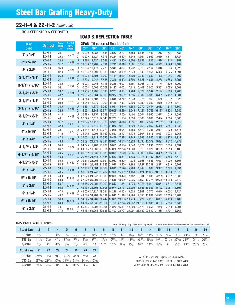
31
10,909 6,982 4,848 3,562 2,727 2,155 1,745 1,443 1,212 891 68210,909 8,727 7,273 6,234 5,455 4,848 4,364 3,967 3,636 3,117 2,72713,636 8,727 6,061 4,453 3,409 2,694 2,182 1,803 1,515 1,113 85213,636 10,909 9,091 7,792 6,818 6,061 5,455 4,959 4,545 3,896 3,40916,364 10,473 7,273 5,343 4,091 3,232 2,618 2,164 1,818 1,336 1,02316,364 13,091 10,909 9,351 8,182 7,273 6,545 5,950 5,455 4,675 4,09112,803 8,194 5,690 4,181 3,201 2,529 2,048 1,693 1,423 1,045 80012,803 10,242 8,535 7,316 6,402 5,690 5,121 4,656 4,268 3,658 3,20116,004 10,242 7,113 5,226 4,001 3,161 2,561 2,116 1,778 1,306 1,00016,004 12,803 10,669 9,145 8,002 7,113 6,402 5,820 5,335 4,573 4,00119,205 12,291 8,535 6,271 4,801 3,793 3,073 2,539 2,134 1,568 1,20019,205 15,364 12,803 10,974 9,602 8,535 7,682 6,983 6,402 5,487 4,80114,848 9,503 6,599 4,848 3,712 2,933 2,376 1,963 1,650 1,212 92814,848 11,879 9,899 8,485 7,424 6,599 5,939 5,399 4,949 4,242 3,71218,561 11,879 8,249 6,061 4,640 3,666 2,970 2,454 2,062 1,515 1,16018,561 14,848 12,374 10,606 9,280 8,249 7,424 6,749 6,187 5,303 4,64022,273 14,255 9,899 7,273 5,568 4,400 3,564 2,945 2,475 1,818 1,39222,273 17,818 14,848 12,727 11,136 9,899 8,909 8,099 7,424 6,364 5,56819,394 12,412 8,620 6,333 4,848 3,831 3,103 2,564 2,155 1,583 1,21219,394 15,515 12,929 11,082 9,697 8,620 7,758 7,052 6,465 5,541 4,84824,242 15,515 10,774 7,916 6,061 4,789 3,879 3,206 2,694 1,979 1,51524,242 19,394 16,162 13,853 12,121 10,774 9,697 8,815 8,081 6,926 6,06129,091 18,618 12,929 9,499 7,273 5,746 4,655 3,847 3,232 2,375 1,81829,091 23,273 19,394 16,623 14,545 12,929 11,636 10,579 9,697 8,312 7,27324,545 15,709 10,909 8,015 6,136 4,848 3,927 3,246 2,727 2,004 1,53424,545 19,636 16,364 14,026 12,273 10,909 9,818 8,926 8,182 7,013 6,13630,682 19,636 13,636 10,019 7,670 6,061 4,909 4,057 3,409 2,505 1,91830,682 24,545 20,455 17,532 15,341 13,636 12,273 11,157 10,227 8,766 7,67036,818 23,564 16,364 12,022 9,205 7,273 5,891 4,869 4,091 3,006 2,30136,818 29,455 24,545 21,039 18,409 16,364 14,727 13,388 12,273 10,519 9,20530,303 19,394 13,468 9,895 7,576 5,986 4,848 4,007 3,367 2,474 1,89430,303 24,242 20,202 17,316 15,152 13,468 12,121 11,019 10,101 8,658 7,57637,879 24,242 16,835 12,369 9,470 7,482 6,061 5,009 4,209 3,092 2,36737,879 30,303 25,253 21,645 18,939 16,835 15,152 13,774 12,626 10,823 9,47045,455 29,091 20,202 14,842 11,364 8,979 7,273 6,011 5,051 3,711 2,84145,455 36,364 30,303 25,974 22,727 20,202 18,182 16,529 15,152 12,987 11,36443,636 27,927 19,394 14,249 10,909 8,620 6,982 5,770 4,848 3,562 2,72743,636 34,909 29,091 24,935 21,818 19,394 17,455 15,868 14,545 12,468 10,90954,545 34,909 24,242 17,811 13,636 10,774 8,727 7,213 6,061 4,453 3,40954,545 43,636 36,364 31,169 27,273 24,242 21,818 19,835 18,182 15,584 13,63665,455 41,891 29,091 21,373 16,364 12,929 10,473 8,655 7,273 5,343 4,09165,455 52,364 43,636 37,403 32,727 29,091 26,182 23,802 21,818 18,701 16,364
22-H-422-H-222-H-422-H-222-H-422-H-222-H-422-H-222-H-422-H-222-H-422-H-222-H-422-H-222-H-422-H-222-H-422-H-222-H-422-H-222-H-422-H-222-H-422-H-222-H-422-H-222-H-422-H-222-H-422-H-222-H-422-H-222-H-422-H-222-H-422-H-222-H-422-H-222-H-422-H-222-H-422-H-2
24" 30" 36" 42" 48" 54" 60" 66" 72" 84" 96"
Approx. Sec. ModBar Symbol Weight Per Ft.Size psf Of Width
3" x 1/4"
3" x 5/16"
3" x 3/8"
3-1/4" x 1/4"
3-1/4" x 5/16"
3-1/4" x 3/8"
3-1/2" x 1/4"
3-1/2" x 5/16"
3-1/2" x 3/8"
4" x 1/4"
4" x 5/16"
4" x 3/8"
4-1/2" x 1/4"
4-1/2" x 5/16"
4-1/2" x 3/8"
5" x 1/4"
5" x 5/16"
5" x 3/8"
6" x 1/4"
6" x 5/16"
6" x 3/8"
3.273
4.091
4.909
3.841
4.801
5.761
4.455
5.568
6.682
5.818
7.273
8.727
7.364
9.205
11.045
9.091
11.364
13.636
13.091
16.364
19.636
SPAN (Direction of Bearing Bar)
LOAD & DEFLECTION TABLE
UCUCUCUCUCUCUCUCUCUCUCUCUCUCUCUCUCUCUCUCUC
24.125.230.231.735.837.426.027.132.634.138.740.227.929.034.936.541.643.131.732.939.741.247.348.835.636.744.546.053.054.539.440.549.350.858.760.247.048.258.860.370.171.8
2 3 4 5 6 7 8 9 10 11 12 13 14 15 16 17 18 19 20
1/4" Bar
5/16" Bar
3/8" Bar
15/8 3 43/8 53/4 71/8 81/2 97/8 111/4 125/8 14 153/8 163/4 181/8 191/2 207/8 221/4 235/8 25 263/8
111/16 31/16 47/16 513/16 73/16 89/16 915/16 115/16 1211/16 141/16 157/16 1613/16 183/16 199/16 2015/16 225/16 2311/16 251/16 267/16
13/4 31/8 41/2 57/8 71/4 85/8 10 113/8 123/4 141/8 151/2 167/8 181/4 195/8 21 223/8 233/4 251/8 261/2
No. of Bars
21 22 23 24 25 26 27
1/4" Bar
5/16" Bar
3/8" Bar
273/4 291/8 301/2 317/8 331/4 345/8 36
2713/16 293/16 309/16 3115/16 335/16 3411/16 361/16
277/8 291/4 305/8 32 333/8 343/4 361/8
No. of Bars
H-22 PANEL WIDTH (inches) Note: H-Heavy Duty cross rods may extend 1/8" each side. Panel widths do not include these extensions.
Steel Bar Grating Heavy-Duty22-H-4 & 22-H-2 (continued)
NON-SERRATED & SERRATED
All 1/4” Bar Size - up to 27 Bars Wide1 x 5/16 thru 2-1/2 x 3/8 - up to 27 Bars Wide2-3/4 x 5/16 thru 6 x 3/8 - up to 18 Bars Wide

32
889 569 395 290 222 176 142 118 99 73 56889 711 593 508 444 395 356 323 296 254 222
1,111 711 494 363 278 219 178 147 123 91 691,111 889 741 635 556 494 444 404 370 317 2781,333 853 593 435 333 263 213 176 148 109 831,333 1,067 889 762 667 593 533 485 444 381 3331,389 889 617 454 347 274 222 184 154 113 871,389 1,111 926 794 694 617 556 505 463 397 3471,736 1,111 772 567 434 343 278 230 193 142 1091,736 1,389 1,157 992 868 772 694 631 579 496 4342,083 1,333 926 680 521 412 333 275 231 170 1302,083 1,667 1,389 1,190 1,042 926 833 758 694 595 5212,000 1,280 889 653 500 395 320 264 222 163 1252,000 1,600 1,333 1,143 1,000 889 800 727 667 571 5002,500 1,600 1,111 816 625 494 400 331 278 204 1562,500 2,000 1,667 1,429 1,250 1,111 1,000 909 833 714 6253,000 1,920 1,333 980 750 593 480 397 333 245 1883,000 2,400 2,000 1,714 1,500 1,333 1,200 1,091 1,000 857 7502,722 1,742 1,210 889 681 538 436 360 302 222 1702,722 2,178 1,815 1,556 1,361 1,210 1,089 990 907 778 6813,403 2,178 1,512 1,111 851 672 544 450 378 278 2133,403 2,722 2,269 1,944 1,701 1,512 1,361 1,237 1,134 972 8514,083 2,613 1,815 1,333 1,021 807 653 540 454 333 2554,083 3,267 2,722 2,333 2,042 1,815 1,633 1,485 1,361 1,167 1,0213,556 2,276 1,580 1,161 889 702 569 470 395 290 2223,556 2,844 2,370 2,032 1,778 1,580 1,422 1,293 1,185 1,016 8894,444 2,844 1,975 1,451 1,111 878 711 588 494 363 2784,444 3,556 2,963 2,540 2,222 1,975 1,778 1,616 1,481 1,270 1,1115,333 3,413 2,370 1,741 1,333 1,053 853 705 593 435 3335,333 4,267 3,556 3,048 2,667 2,370 2,133 1,939 1,778 1,524 1,3334,500 2,880 2,000 1,469 1,125 889 720 595 500 367 2814,500 3,600 3,000 2,571 2,250 2,000 1,800 1,636 1,500 1,286 1,1255,625 3,600 2,500 1,837 1,406 1,111 900 744 625 459 3525,625 4,500 3,750 3,214 2,813 2,500 2,250 2,045 1,875 1,607 1,4066,750 4,320 3,000 2,204 1,688 1,333 1,080 893 750 551 4226,750 5,400 4,500 3,857 3,375 3,000 2,700 2,455 2,250 1,929 1,6885,556 3,556 2,469 1,814 1,389 1,097 889 735 617 454 3475,556 4,444 3,704 3,175 2,778 2,469 2,222 2,020 1,852 1,587 1,3896,944 4,444 3,086 2,268 1,736 1,372 1,111 918 772 567 4346,944 5,556 4,630 3,968 3,472 3,086 2,778 2,525 2,315 1,984 1,7368,333 5,333 3,704 2,721 2,083 1,646 1,333 1,102 926 680 5218,333 6,667 5,556 4,762 4,167 3,704 3,333 3,030 2,778 2,381 2,0836,722 4,302 2,988 2,195 1,681 1,328 1,076 889 747 549 4206,722 5,378 4,481 3,841 3,361 2,988 2,689 2,444 2,241 1,921 1,6818,403 5,378 3,735 2,744 2,101 1,660 1,344 1,111 934 686 5258,403 6,722 5,602 4,802 4,201 3,735 3,361 3,056 2,801 2,401 2,10110,083 6,453 4,481 3,293 2,521 1,992 1,613 1,333 1,120 823 63010,083 8,067 6,722 5,762 5,042 4,481 4,033 3,667 3,361 2,881 2,521
30-H-430-H-230-H-430-H-230-H-430-H-230-H-430-H-230-H-430-H-230-H-430-H-230-H-430-H-230-H-430-H-230-H-430-H-230-H-430-H-230-H-430-H-230-H-430-H-230-H-430-H-230-H-430-H-230-H-430-H-230-H-430-H-230-H-430-H-230-H-430-H-230-H-430-H-230-H-430-H-230-H-430-H-230-H-430-H-230-H-430-H-230-H-430-H-2
24" 30" 36" 42" 48" 54" 60" 66" 72" 84" 96"
Approx. Sec. ModBar Symbol Weight Per Ft.Size psf Of Width
1" x 1/4"
1" x 5/16"
1" x 3/8"
1-1/4" x 1/4"
1-1/4" x 5/16"
1-1/4" x 3/8"
1-1/2" x 1/4"
1-1/2" x 5/16"
1-1/2" x 3/8"
1-3/4" x 1/4"
1-3/4" x 5/16"
1-3/4" x 3/8"
2" x 1/4"
2" x 5/16"
2" x 3/8"
2-1/4" x 1/4"
2-1/4" x 5/16"
2-1/4" x 3/8"
2-1/2" x 1/4"
2-1/2" x 5/16"
2-1/2" x 3/8"
2-3/4" x 1/4"
2-3/4" x 5/16"
2-3/4" x 3/8"
0.267
0.333
0.400
0.417
0.521
0.625
0.600
0.750
0.900
0.817
1.021
1.225
1.067
1.333
1.600
1.350
1.688
2.025
1.667
2.083
2.500
2.017
2.521
3.025
SPAN (Direction of Bearing Bar)
LOAD & DEFLECTION TABLE
UCUCUCUCUCUCUCUCUCUCUCUCUCUCUCUCUCUCUCUCUCUCUCUC
6.37.08.29.49.610.87.88.410.011.111.812.99.29.811.812.913.915.010.611.313.614.716.017.112.012.715.316.518.119.313.614.117.118.220.321.414.915.318.920.022.323.516.317.021.022.624.926.4
Cross Rods 4" C/C Cross Rods 2" C/C
30-H-4 30-H-2 U=safe uniform load, psf (page 93)C= safe concentrated load, psf (page 93)D=deflection, inchesE =modulus of elasticity, 29,000,000 psiF = fiber stress, 20,000 psiMaterial: ASTM A-36Serrated Bars: For serrated grating, the depth of grating required for a spec-ified load is 1/4" deeper than that shown in the table.General: Loads and deflections are theoretical and based on static loading.Deflection: Spans and loads to the right of the bold line exceed 1/4" deflec-tion for uniform load of 100 psf which provides safe pedestrian comfort.These can be exceeded for other types of loads with engineer’s approval.For deflections of uniform and concentrated loads, consult AMICO-Klemp®’sengineering departments.
Steel Bar Grating Heavy-DutyHEAVY-DUTY WELDED (W) 1-7/8" C/C Bearing Bars
NON-SERRATED & SERRATED

33
8,000 5,120 3,556 2,612 2,000 1,580 1,280 1,058 889 653 5008,000 6,400 5,333 4,571 4,000 3,556 3,200 2,909 2,667 2,286 2,00010,000 6,400 4,444 3,265 2,500 1,975 1,600 1,322 1,111 816 62510,000 8,000 6,667 5,714 5,000 4,444 4,000 3,636 3,333 2,857 2,50012,000 7,680 5,333 3,918 3,000 2,370 1,920 1,587 1,333 980 75012,000 9,600 8,000 6,857 6,000 5,333 4,800 4,364 4,000 3,429 3,0009,389 6,009 4,173 3,066 2,347 1,855 1,502 1,242 1,043 766 5879,389 7,511 6,259 5,365 4,694 4,173 3,756 3,414 3,130 2,683 2,34711,736 7,511 5,216 3,832 2,934 2,318 1,878 1,552 1,304 958 73411,736 9,389 7,824 6,706 5,868 5,216 4,694 4,268 3,912 3,353 2,93414,083 9,013 6,259 4,599 3,521 2,782 2,253 1,862 1,565 1,150 88014,083 11,267 9,389 8,048 7,042 6,259 5,633 5,121 4,694 4,024 3,52110,889 6,969 4,840 3,556 2,722 2,151 1,742 1,440 1,210 889 68110,889 8,711 7,259 6,222 5,444 4,840 4,356 3,960 3,630 3,111 2,72213,611 8,711 6,049 4,444 3,403 2,689 2,178 1,800 1,512 1,111 85113,611 10,889 9,074 7,778 6,806 6,049 5,444 4,949 4,537 3,889 3,40316,333 10,453 7,259 5,333 4,083 3,226 2,613 2,160 1,815 1,333 1,02116,333 13,067 10,889 9,333 8,167 7,259 6,533 5,939 5,444 4,667 4,08314,222 9,102 6,321 4,644 3,556 2,809 2,276 1,881 1,580 1,161 88914,222 11,378 9,481 8,127 7,111 6,321 5,689 5,172 4,741 4,063 3,55617,778 11,378 7,901 5,805 4,444 3,512 2,844 2,351 1,975 1,451 1,11117,778 14,222 11,852 10,159 8,889 7,901 7,111 6,465 5,926 5,079 4,44421,333 13,653 9,481 6,966 5,333 4,214 3,413 2,821 2,370 1,741 1,33321,333 17,067 14,222 12,190 10,667 9,481 8,533 7,758 7,111 6,095 5,33318,000 11,520 8,000 5,878 4,500 3,556 2,880 2,380 2,000 1,469 1,12518,000 14,400 12,000 10,286 9,000 8,000 7,200 6,545 6,000 5,143 4,50022,500 14,400 10,000 7,347 5,625 4,444 3,600 2,975 2,500 1,837 1,40622,500 18,000 15,000 12,857 11,250 10,000 9,000 8,182 7,500 6,429 5,62527,000 17,280 12,000 8,816 6,750 5,333 4,320 3,570 3,000 2,204 1,68827,000 21,600 18,000 15,429 13,500 12,000 10,800 9,818 9,000 7,714 6,75022,222 14,222 9,877 7,256 5,556 4,390 3,556 2,938 2,469 1,814 1,38922,222 17,778 14,815 12,698 11,111 9,877 8,889 8,081 7,407 6,349 5,55627,778 17,778 12,346 9,070 6,944 5,487 4,444 3,673 3,086 2,268 1,73627,778 22,222 18,519 15,873 13,889 12,346 11,111 10,101 9,259 7,937 6,94433,333 21,333 14,815 10,884 8,333 6,584 5,333 4,408 3,704 2,721 2,08333,333 26,667 22,222 19,048 16,667 14,815 13,333 12,121 11,111 9,524 8,33332,000 20,480 14,222 10,449 8,000 6,321 5,120 4,231 3,556 2,612 2,00032,000 25,600 21,333 18,286 16,000 14,222 12,800 11,636 10,667 9,143 8,00040,000 25,600 17,778 13,061 10,000 7,901 6,400 5,289 4,444 3,265 2,50040,000 32,000 26,667 22,857 20,000 17,778 16,000 14,545 13,333 11,429 10,00048,000 30,720 21,333 15,673 12,000 9,481 7,680 6,347 5,333 3,918 3,00048,000 38,400 32,000 27,429 24,000 21,333 19,200 17,455 16,000 13,714 12,000
30-H-430-H-230-H-430-H-230-H-430-H-230-H-430-H-230-H-430-H-230-H-430-H-230-H-430-H-230-H-430-H-230-H-430-H-230-H-430-H-230-H-430-H-230-H-430-H-230-H-430-H-230-H-430-H-230-H-430-H-230-H-430-H-230-H-430-H-230-H-430-H-230-H-430-H-230-H-430-H-230-H-430-H-2
24" 30" 36" 42" 48" 54" 60" 66" 72" 84" 96"
Approx. Sec. ModBar Symbol Weight Per Ft.Size psf Of Width
3" x 1/4"
3" x 5/16"
3" x 3/8"
3-1/4" x 1/4"
3-1/4" x 5/16"
3-1/4" x 3/8"
3-1/2" x 1/4"
3-1/2" x 5/16"
3-1/2" x 3/8"
4" x 1/4"
4" x 5/16"
4" x 3/8"
4-1/2" x 1/4"
4-1/2" x 5/16"
4-1/2" x 3/8"
5" x 1/4"
5" x 5/16"
5" x 3/8"
6" x 1/4"
6" x 5/16"
6" x 3/8"
2.400
3.000
3.600
2.817
3.521
4.225
3.267
4.083
4.900
4.267
5.333
6.400
5.400
6.750
8.100
6.667
8.333
10.000
9.600
12.000
14.400
SPAN (Direction of Bearing Bar)
LOAD & DEFLECTION TABLE
UCUCUCUCUCUCUCUCUCUCUCUCUCUCUCUCUCUCUCUCUC
18.219.322.824.427.028.619.620.724.626.129.230.721.022.226.427.931.332.823.929.029.931.535.537.136.727.933.535.039.941.329.730.737.038.644.045.635.336.444.145.752.554.0
2 3 4 5 6 7 8 9 10 11 12 13 14 15 16 17 18 19 20
1/4" Bar
5/16" Bar
3/8" Bar
21/8 4 57/8 73/4 95/8 111/2 133/8 151/4 171/8 19 207/8 223/4 245/8 261/2 283/8 301/4 321/8 34 357/8
23/16 41/16 515/16 713/16 911/16 119/16 137/16 155/16 173/16 191/16 2015/16 2213/16 2411/16 269/16 287/16 305/16 323/16 341/16 3515/16
21/4 41/8 6 77/8 93/4 115/8 131/2 153/8 171/4 191/8 21 227/8 243/4 265/8 281/2 303/8 321/4 341/8 36
No. of Bars
H-30 PANEL WIDTH (inches) Note: H-Heavy Duty cross rods may extend 1/8" each side. Panel widths do not include these extensions.
Steel Bar Grating Heavy-Duty30-H-4 & 30-H-2 (continued)
NON-SERRATED & SERRATED

34
702 449 312 229 175 139 112 93 78 57 44702 561 468 401 351 312 281 255 234 201 175877 561 390 286 219 173 140 116 97 72 55877 702 585 501 439 390 351 319 292 251 219
1,053 674 468 344 263 208 168 139 117 86 661,053 842 702 602 526 468 421 383 351 301 2631,096 702 487 358 274 217 175 145 122 90 691,096 877 731 627 548 487 439 399 365 313 2741,371 877 609 448 343 271 219 181 152 112 861,371 1,096 914 783 685 609 548 498 457 392 3431,645 1,053 731 537 411 325 263 217 183 134 1031,645 1,316 1,096 940 822 731 658 598 548 470 4111,579 1,011 702 516 395 312 253 209 175 129 991,579 1,263 1,053 902 789 702 632 574 526 451 3951,974 1,263 877 644 493 390 316 261 219 161 1231,974 1,579 1,316 1,128 987 877 789 718 658 564 4932,368 1,516 1,053 773 592 468 379 313 263 193 1482,368 1,895 1,579 1,353 1,184 1,053 947 861 789 677 5922,149 1,375 955 702 537 425 344 284 239 175 1342,149 1,719 1,433 1,228 1,075 955 860 781 716 614 5372,686 1,719 1,194 877 672 531 430 355 298 219 1682,686 2,149 1,791 1,535 1,343 1,194 1,075 977 895 768 6723,224 2,063 1,433 1,053 806 637 516 426 358 263 2013,224 2,579 2,149 1,842 1,612 1,433 1,289 1,172 1,075 921 8062,807 1,796 1,248 917 702 554 449 371 312 229 1752,807 2,246 1,871 1,604 1,404 1,248 1,123 1,021 936 802 7023,509 2,246 1,559 1,146 877 693 561 464 390 286 2193,509 2,807 2,339 2,005 1,754 1,559 1,404 1,276 1,170 1,003 8774,211 2,695 1,871 1,375 1,053 832 674 557 468 344 2634,211 3,368 2,807 2,406 2,105 1,871 1,684 1,531 1,404 1,203 1,0533,553 2,274 1,579 1,160 888 702 568 470 395 290 2223,553 2,842 2,368 2,030 1,776 1,579 1,421 1,292 1,184 1,015 8884,441 2,842 1,974 1,450 1,110 877 711 587 493 363 2784,441 3,553 2,961 2,538 2,220 1,974 1,776 1,615 1,480 1,269 1,1105,329 3,411 2,368 1,740 1,332 1,053 853 705 592 435 3335,329 4,263 3,553 3,045 2,664 2,368 2,132 1,938 1,776 1,523 1,3324,386 2,807 1,949 1,432 1,096 866 702 580 487 358 2744,386 3,509 2,924 2,506 2,193 1,949 1,754 1,595 1,462 1,253 1,0965,482 3,509 2,437 1,790 1,371 1,083 877 725 609 448 3435,482 4,386 3,655 3,133 2,741 2,437 2,193 1,994 1,827 1,566 1,3716,579 4,211 2,924 2,148 1,645 1,300 1,053 870 731 537 4116,579 5,263 4,386 3,759 3,289 2,924 2,632 2,392 2,193 1,880 1,6455,307 3,396 2,359 1,733 1,327 1,048 849 702 590 433 3325,307 4,246 3,538 3,033 2,654 2,359 2,123 1,930 1,769 1,516 1,3276,634 4,246 2,948 2,166 1,658 1,310 1,061 877 737 542 4156,634 5,307 4,423 3,791 3,317 2,948 2,654 2,412 2,211 1,895 1,6587,961 5,095 3,538 2,599 1,990 1,572 1,274 1,053 885 650 4987,961 6,368 5,307 4,549 3,980 3,538 3,184 2,895 2,654 2,274 1,990
38-H-438-H-238-H-438-H-238-H-438-H-238-H-438-H-238-H-438-H-238-H-438-H-238-H-438-H-238-H-438-H-238-H-438-H-238-H-438-H-238-H-438-H-238-H-438-H-238-H-438-H-238-H-438-H-238-H-438-H-238-H-438-H-238-H-438-H-238-H-438-H-238-H-438-H-238-H-438-H-238-H-438-H-238-H-438-H-238-H-438-H-238-H-438-H-2
24" 30" 36" 42" 48" 54" 60" 66" 72" 84" 96"
Approx. Sec. ModBar Symbol Weight Per Ft.Size psf Of Width
1" x 1/4"
1" x 5/16"
1" x 3/8"
1-1/4" x 1/4"
1-1/4" x 5/16"
1-1/4" x 3/8"
1-1/2" x 1/4"
1-1/2" x 5/16"
1-1/2" x 3/8"
1-3/4" x 1/4"
1-3/4" x 5/16"
1-3/4" x 3/8"
2" x 1/4"
2" x 5/16"
2" x 3/8"
2-1/4" x 1/4"
2-1/4" x 5/16"
2-1/4" x 3/8"
2-1/2" x 1/4"
2-1/2" x 5/16"
2-1/2" x 3/8"
2-3/4" x 1/4"
2-3/4" x 5/16"
2-3/4" x 3/8"
0.211
0.263
0.316
0.329
0.411
0.493
0.474
0.592
0.711
0.645
0.806
0.967
0.842
1.053
1.263
1.066
1.332
1.599
1.316
1.645
1.974
1.592
1.990
2.388
SPAN (Direction of Bearing Bar)
LOAD & DEFLECTION TABLE
UCUCUCUCUCUCUCUCUCUCUCUCUCUCUCUCUCUCUCUCUCUCUCUC
5.25.96.87.97.99.18.37.08.29.49.610.87.58.19.610.811.312.58.69.311.112.213.014.29.810.412.513.614.715.910.911.513.915.016.417.612.012.715.316.518.119.313.213.817.218.720.221.8
Cross Rods 4" C/C Cross Rods 2" C/C
38-H-4 38-H-2 U=safe uniform load, psf (page 93)C= safe concentrated load, psf (page 93)D=deflection, inchesE =modulus of elasticity, 29,000,000 psiF = fiber stress, 20,000 psiMaterial: ASTM A-36Serrated Bars: For serrated grating, the depth of grating required for aspecified load is 1/4" deeper than that shown in the table.General: Loads and deflections are theoretical and based on static loading.Deflection: Spans and loads to the right of the bold line exceed 1/4" deflec-tion for uniform load of 100 psf which provides safe pedestrian comfort.These can be exceeded for other types of loads with engineer’s approval.For deflections of uniform and concentrated loads, consult AMICO-Klemp®’sengineering departments.
Steel Bar Grating Heavy-DutyHEAVY-DUTY WELDED (H) 2-3/8" C/C Bearing Bars
NON-SERRATED & SERRATED

35
6,316 4,042 2,807 2,062 1,579 1,248 1,011 835 702 516 3956,316 5,053 4,211 3,609 3,158 2,807 2,526 2,297 2,105 1,805 1,5797,895 5,053 3,509 2,578 1,974 1,559 1,263 1,044 877 644 4937,895 6,316 5,263 4,511 3,947 3,509 3,158 2,871 2,632 2,256 1,9749,474 6,063 4,211 3,093 2,368 1,871 1,516 1,253 1,053 773 5929,474 7,579 6,316 5,414 4,737 4,211 3,789 3,445 3,158 2,707 2,3687,412 4,744 3,294 2,420 1,853 1,464 1,186 980 824 605 4637,412 5,930 4,942 4,236 3,706 3,294 2,965 2,695 2,471 2,118 1,8539,265 5,930 4,118 3,025 2,316 1,830 1,482 1,225 1,029 756 5799,265 7,412 6,177 5,294 4,633 4,118 3,706 3,369 3,088 2,647 2,31611,118 7,116 4,942 3,631 2,780 2,196 1,779 1,470 1,235 908 69511,118 8,895 7,412 6,353 5,559 4,942 4,447 4,043 3,706 3,177 2,7808,596 5,502 3,821 2,807 2,149 1,698 1,375 1,137 955 702 5378,596 6,877 5,731 4,912 4,298 3,821 3,439 3,126 2,865 2,456 2,14910,746 6,877 4,776 3,509 2,686 2,123 1,719 1,421 1,194 877 67210,746 8,596 7,164 6,140 5,373 4,776 4,298 3,907 3,582 3,070 2,68612,895 8,253 5,731 4,211 3,224 2,547 2,063 1,705 1,433 1,053 80612,895 10,316 8,596 7,368 6,447 5,731 5,158 4,689 4,298 3,684 3,22411,228 7,186 4,990 3,666 2,807 2,218 1,796 1,485 1,248 917 70211,228 8,982 7,485 6,416 5,614 4,990 4,491 4,083 3,743 3,208 2,80714,035 8,982 6,238 4,583 3,509 2,772 2,246 1,856 1,559 1,146 87714,035 11,228 9,357 8,020 7,018 6,238 5,614 5,104 4,678 4,010 3,50916,842 10,779 7,485 5,499 4,211 3,327 2,695 2,227 1,871 1,375 1,05316,842 13,474 11,228 9,624 8,421 7,485 6,737 6,124 5,614 4,812 4,21114,211 9,095 6,316 4,640 3,553 2,807 2,274 1,879 1,579 1,160 88814,211 11,368 9,474 8,120 7,105 6,316 5,684 5,167 4,737 4,060 3,55317,763 11,368 7,895 5,800 4,441 3,509 2,842 2,349 1,974 1,450 1,11017,763 14,211 11,842 10,150 8,882 7,895 7,105 6,459 5,921 5,075 4,44121,316 13,642 9,474 6,960 5,329 4,211 3,411 2,819 2,368 1,740 1,33221,316 17,053 14,211 12,180 10,658 9,474 8,526 7,751 7,105 6,090 5,32917,544 11,228 7,797 5,729 4,386 3,465 2,807 2,320 1,949 1,432 1,09617,544 14,035 11,696 10,025 8,772 7,797 7,018 6,380 5,848 5,013 4,38621,930 14,035 9,747 7,161 5,482 4,332 3,509 2,900 2,437 1,790 1,37121,930 17,544 14,620 12,531 10,965 9,747 8,772 7,974 7,310 6,266 5,48226,316 16,842 11,696 8,593 6,579 5,198 4,211 3,480 2,924 2,148 1,64526,316 21,053 17,544 15,038 13,158 11,696 10,526 9,569 8,772 7,519 6,57925,263 16,168 11,228 8,249 6,316 4,990 4,042 3,341 2,807 2,062 1,57925,263 20,211 16,842 14,436 12,632 11,228 10,105 9,187 8,421 7,218 6,31631,579 20,211 14,035 10,311 7,895 6,238 5,053 4,176 3,509 2,578 1,97431,579 25,263 21,053 18,045 15,789 14,035 12,632 11,483 10,526 9,023 7,89537,895 24,253 16,842 12,374 9,474 7,485 6,063 5,011 4,211 3,093 2,36837,895 30,316 25,263 21,654 18,947 16,842 15,158 13,780 12,632 10,827 9,474
38-H-438-H-238-H-438-H-238-H-438-H-238-H-438-H-238-H-438-H-238-H-438-H-238-H-438-H-238-H-438-H-238-H-438-H-238-H-438-H-238-H-438-H-238-H-438-H-238-H-438-H-238-H-438-H-238-H-438-H-238-H-438-H-238-H-438-H-238-H-438-H-238-H-438-H-238-H-438-H-238-H-438-H-2
24" 30" 36" 42" 48" 54" 60" 66" 72" 84" 96"
Approx. Sec. ModBar Symbol Weight Per Ft.Size psf Of Width
3" x 1/4"
3" x 5/16"
3" x 3/8"
3-1/4" x 1/4"
3-1/4" x 5/16"
3-1/4" x 3/8"
3-1/2" x 1/4"
3-1/2" x 5/16"
3-1/2" x 3/8"
4" x 1/4"
4" x 5/16"
4" x 3/8"
4-1/2" x 1/4"
4-1/2" x 5/16"
4-1/2" x 3/8"
5" x 1/4"
5" x 5/16"
5" x 3/8"
6" x 1/4"
6" x 5/16"
6" x 3/8"
1.895
2.368
2.842
2.224
2.780
3.336
2.579
3.224
3.868
3.368
4.211
5.053
4.263
5.329
6.395
5.263
6.579
7.895
7.579
9.474
11.368
SPAN (Direction of Bearing Bar)
LOAD & DEFLECTION TABLE
UCUCUCUCUCUCUCUCUCUCUCUCUCUCUCUCUCUCUCUCUC
14.915.918.620.121.923.515.917.120.021.523.625.217.118.221.422.925.326.919.320.524.225.828.30.321.622.727.128.632.133.723.925.029.931.535.537.128.429.835.637.142.343.9
2 3 4 5 6 7 8 9 10 11 12 13 14 15 16
1/4" Bar
5/16" Bar
3/8" Bar
25/8 5 73/8 93/4 121/8 141/2 167/8 191/4 215/8 24 263/8 283/4 311/8 331/2 357/8
211/16 51/16 77/16 913/16 123/16 149/16 1615/16 195/16 2111/16 241/16 267/16 2813/16 313/16 339/16 3515/16
23/4 51/8 71/2 97/8 121/4 145/8 17 193/8 213/4 241/8 261/2 287/8 311/4 335/8 36
No. of Bars
H-38 PANEL WIDTH (inches) Note: H-Heavy Duty cross rods may extend 1/8" each side. Panel widths do not include these extensions.
Steel Bar Grating Heavy-Duty38-H-4 & 38-H-2 (continued)
NON-SERRATED & SERRATED

3636
Corrosion resistant, non-sparking, rustproof aluminum grating has manyapplications due to its light weight and high strength. It is ideally suitedfor use in corrosive environments and finds wide applications as walk-ways and platforms in sewage treatment plants, refineries, chemical pro-cessing plants, pumping and compressor stations, and aboard ships andbarges. Because it does not rust, it is commonly used in breweries, bot-tling plants, and food preparation and storage facilities. In munitionplants, other volatile industries and areas, its non-sparking propertiesmake it a must for safety. It is available in standard or anodized finishes.
Swage-Locked II-Bar Grating is the most widely used and providesthe strength equal to a rectangular bar of the same depth, but at far lessweight and cost. The I-bars are permanently locked to the cross rods(positioned every 2" or 4") by a swaging process.
Swage-Locked Rectangular Bar Grating uses the swaging processto permanently lock the cross rods (positioned every 2" or 4") to the rec-tangular bars.
Press-Locked Rectangular Bar Grating is constructed with the twoclose-tolerance slotted bars bonded together (positioned every 2" or 4")using tremendous hydraulic pressure. Permanent locking is achieved byforcing the deep cross bar into the bearing bar. Both the cross bars andthe bearing bars provide walking surfaces in the press-locked design.
Rectangular bar grating in either the swage-locked or press-lockedstyles is your best choice when lateral stiffness is required. The rectangu-lar bar is also available in a serrated surface for additional safety.
19-SII-4 19-SII-2
15-SII-4 15-SII-2
SWAGE-LOCKED I-BAR ALUMINUM GRATING
19-SR-4 19-SR-2
15-SR-4 15-SR-2
SWAGE-LOCKED RECTANGULAR BAR ALUMINUM GRATING PRESS-LOCKED RECTANGULAR BAR ALUMINUM GRATING
19-AP-4 19-AP-2
15-AP-4 15-AP-2
13-AP-4 13-AP-2
10-AP-4 10-AP-2
11-SR-4 11-SR-2
11-AP-4 11-AP-28-SR-4 8-SR-2
8-AP-4 8-AP-2
7-AP-27-AP-4
8-SII-4 8-SII-2
11-SII-4 11-SII-2
Aluminum Bar Grating
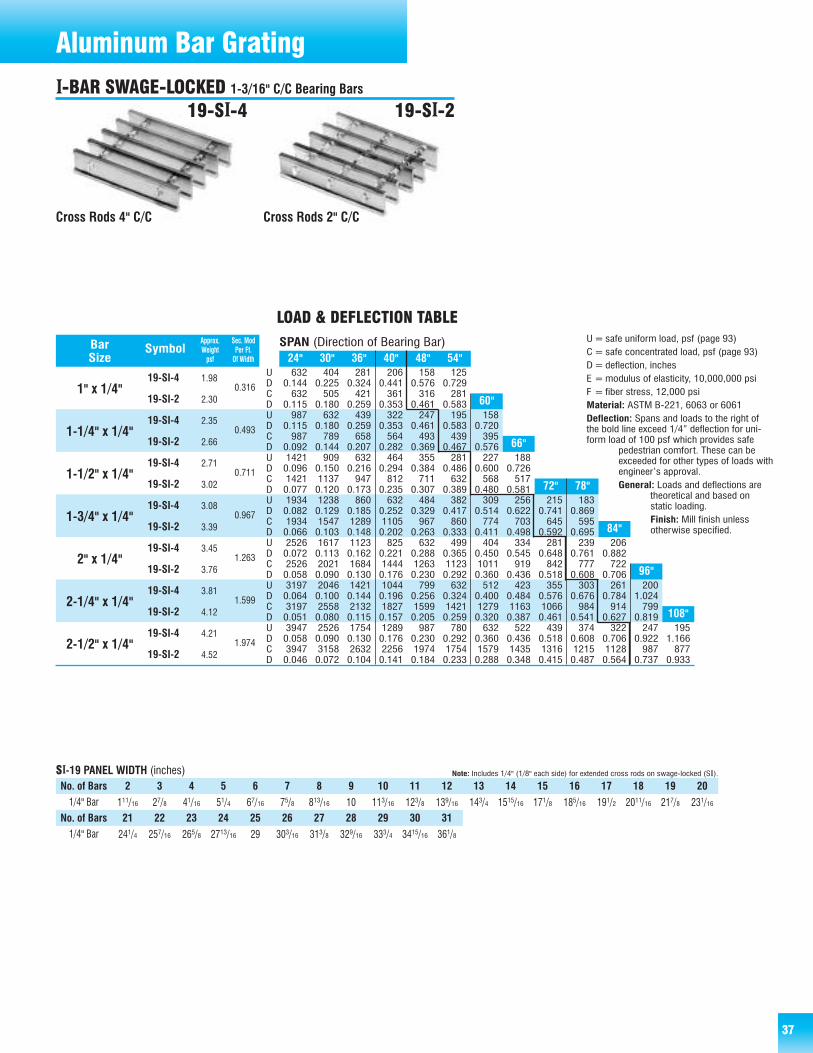
3737
632 404 281 206 158 1250.144 0.225 0.324 0.441 0.576 0.729632 505 421 361 316 281
0.115 0.180 0.259 0.353 0.461 0.583987 632 439 322 247 195 158
0.115 0.180 0.259 0.353 0.461 0.583 0.720987 789 658 564 493 439 395
0.092 0.144 0.207 0.282 0.369 0.467 0.5761421 909 632 464 355 281 227 1880.096 0.150 0.216 0.294 0.384 0.486 0.600 0.7261421 1137 947 812 711 632 568 5170.077 0.120 0.173 0.235 0.307 0.389 0.480 0.5811934 1238 860 632 484 382 309 256 215 1830.082 0.129 0.185 0.252 0.329 0.417 0.514 0.622 0.741 0.8691934 1547 1289 1105 967 860 774 703 645 5950.066 0.103 0.148 0.202 0.263 0.333 0.411 0.498 0.592 0.6952526 1617 1123 825 632 499 404 334 281 239 2060.072 0.113 0.162 0.221 0.288 0.365 0.450 0.545 0.648 0.761 0.8822526 2021 1684 1444 1263 1123 1011 919 842 777 7220.058 0.090 0.130 0.176 0.230 0.292 0.360 0.436 0.518 0.608 0.7063197 2046 1421 1044 799 632 512 423 355 303 261 2000.064 0.100 0.144 0.196 0.256 0.324 0.400 0.484 0.576 0.676 0.784 1.0243197 2558 2132 1827 1599 1421 1279 1163 1066 984 914 7990.051 0.080 0.115 0.157 0.205 0.259 0.320 0.387 0.461 0.541 0.627 0.8193947 2526 1754 1289 987 780 632 522 439 374 322 247 1950.058 0.090 0.130 0.176 0.230 0.292 0.360 0.436 0.518 0.608 0.706 0.922 1.1663947 3158 2632 2256 1974 1754 1579 1435 1316 1215 1128 987 8770.046 0.072 0.104 0.141 0.184 0.233 0.288 0.348 0.415 0.487 0.564 0.737 0.933
19-SI-4
19-SI-2
19-SI-4
19-SI-2
19-SI-4
19-SI-2
19-SI-4
19-SI-2
19-SI-4
19-SI-2
19-SI-4
19-SI-2
19-SI-4
19-SI-2
24" 30" 36" 40" 48" 54"
72" 78"
60"
66"
84"
96"
108"
Approx. Sec. ModBar Symbol Weight Per Ft.Size psf Of Width
1" x 1/4"
1-1/4" x 1/4"
1-1/2" x 1/4"
1-3/4" x 1/4"
2" x 1/4"
2-1/4" x 1/4"
2-1/2" x 1/4"
0.316
0.493
0.711
0.967
1.263
1.599
1.974
1.98
2.30
2.35
2.66
2.71
3.02
3.08
3.39
3.45
3.76
3.81
4.12
4.21
4.52
SPAN (Direction of Bearing Bar)
LOAD & DEFLECTION TABLE
UDCDUDCDUDCDUDCDUDCDUDCDUDCD
U=safe uniform load, psf (page 93)C= safe concentrated load, psf (page 93)D=deflection, inchesE =modulus of elasticity, 10,000,000 psiF = fiber stress, 12,000 psiMaterial: ASTM B-221, 6063 or 6061Deflection: Spans and loads to the right ofthe bold line exceed 1/4” deflection for uni-form load of 100 psf which provides safe
pedestrian comfort. These can beexceeded for other types of loads withengineer’s approval.General: Loads and deflections are
theoretical and based onstatic loading.Finish: Mill finish unlessotherwise specified.
Aluminum Bar Grating
Cross Rods 4" C/C Cross Rods 2" C/C
19-SII-4 19-SII-2
2 3 4 5 6 7 8 9 10 11 12 13 14 15 16 17 18 19 20
111/16 27/8 41/16 51/4 67/16 75/8 813/16 10 113/16 123/8 139/16 143/4 1515/16 171/8 185/16 191/2 2011/16 217/8 231/16
241/4 257/16 265/8 2713/16 29 303/16 313/8 329/16 333/4 3415/16 361/8
21 22 23 24 25 26 27 28 29 30 31
SII-19 PANEL WIDTH (inches) Note: Includes 1/4" (1/8" each side) for extended cross rods on swage-locked (SI).
No. of Bars1/4" Bar
1/4" Bar
No. of Bars
II-BAR SWAGE-LOCKED 1-3/16" C/C Bearing Bars

38
Cross Rods 4" C/C Cross Rods 2" C/C
15-SII-4 15-SII-2
2 3 4 5 6 7 8 9 10 11 12 13 14 15 16 17 18 19 20
17/16 23/8 35/16 41/4 53/16 61/8 71/16 8 815/16 97/8 1013/16 113/4 1211/16 135/8 149/16 151/2 167/16 173/8 185/16
191/4 203/16 211/8 221/16 23 2315/16 247/8 2513/16 263/4 2711/16 285/8 299/16 301/2 317/16 323/8 335/16 341/4 353/16 361/8
21 22 23 24 25 26 27 28 29 30 31 32 33 34 35 36 37 38 39
SII-15 PANEL WIDTH (inches) Note: Includes 1/4" (1/8" each side) for extended cross rods on swage-locked (SI).
No. of Bars1/4" Bar
1/4" Bar
No. of Bars
800 512 356 261 200 1580.144 0.225 0.324 0.441 0.576 0.729800 640 533 457 400 356
0.115 0.180 0.259 0.353 0.461 0.5831250 800 556 408 313 247 200 1650.115 0.180 0.259 0.353 0.461 0.583 0.720 0.8711250 1000 833 714 625 556 500 4550.092 0.144 0.207 0.282 0.369 0.467 0.576 0.6971800 1152 800 588 450 356 288 238 2000.096 0.150 0.216 0.294 0.384 0.486 0.600 0.726 0.8641800 1440 1200 1029 900 800 720 655 6000.077 0.120 0.173 0.235 0.307 0.389 0.480 0.581 0.6912450 1568 1089 800 613 484 392 324 272 2320.082 0.129 0.185 0.252 0.329 0.417 0.514 0.622 0.741 0.8692450 1960 1633 1400 1225 1089 980 891 817 7540.066 0.103 0.148 0.202 0.263 0.333 0.411 0.498 0.592 0.6953200 2048 1422 1045 800 632 512 423 356 303 2610.072 0.113 0.162 0.221 0.288 0.365 0.450 0.545 0.648 0.761 0.8823200 2560 2133 1829 1600 1422 1280 1164 1067 985 9140.058 0.090 0.130 0.176 0.230 0.292 0.360 0.436 0.518 0.608 0.7064050 2592 1800 1322 1013 800 648 536 450 383 331 253 2000.064 0.100 0.144 0.196 0.256 0.324 0.400 0.484 0.576 0.676 0.784 1.024 1.2964050 3240 2700 2314 2025 1800 1620 1473 1350 1246 1157 1013 9000.051 0.080 0.115 0.157 0.205 0.259 0.320 0.387 0.461 0.541 0.627 0.819 1.0375000 3200 2222 1633 1250 988 800 661 556 473 408 313 2470.058 0.090 0.130 0.176 0.230 0.292 0.360 0.436 0.518 0.608 0.706 0.922 1.1665000 4000 3333 2857 2500 2222 2000 1818 1667 1538 1429 1250 11110.046 0.072 0.104 0.141 0.184 0.233 0.288 0.348 0.415 0.487 0.564 0.737 0.933
15-SI-4
15-SI-2
15-SI-4
15-SI-2
15-SI-4
15-SI-2
15-SI-4
15-SI-2
15-SI-4
15-SI-2
15-SI-4
15-SI-2
15-SI-4
15-SI-2
78"
60" 66"
72"
84"
96" 108"
Approx. Sec. ModBar Symbol Weight Per Ft.Size psf Of Width
1" x 1/4"
1-1/4" x 1/4"
1-1/2" x 1/4"
1-3/4" x 1/4"
2" x 1/4"
2-1/4" x 1/4"
2-1/2" x 1/4"
0.400
0.625
0.900
1.225
1.600
2.025
2.500
2.42
2.73
2.90
3.19
3.34
3.64
3.79
4.10
4.26
4.57
4.71
5.02
5.21
5.52
SPAN (Length of Bearing Bar)
LOAD & DEFLECTION TABLE
UDCDUDCDUDCDUDCDUDCDUDCDUDCD
U=safe uniform load, psf (page 93)C= safe concentrated load, psf (page 93)D=deflection, inchesE =modulus of elasticity, 10,000,000 psiF = fiber stress, 12,000 psiMaterial: ASTM B-221, 6063 or 6061Deflection: Spans and loads to the right ofthe bold line exceed 1/4” deflection for uni-form load of 100 psf which provides safe
pedestrian comfort. These can beexceeded for other types of loads withengineer’s approval.General: Loads and deflections are
theoretical and based on static loading.Finish: Mill finish unless otherwise specified.
24" 30" 36" 42" 48" 54"
38
Aluminum Bar GratingII-BAR SWAGE-LOCKED 15/16" C/C Bearing Bars
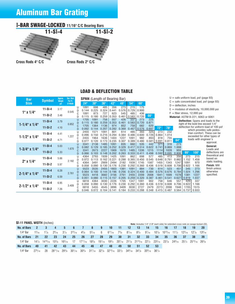
39
U=safe uniform load, psf (page 93)C= safe concentrated load, psf (page 93)D=deflection, inchesE =modulus of elasticity, 10,000,000 psiF = fiber stress, 12,000 psiMaterial: ASTM B-221, 6063 or 6061
Deflection: Spans and loads to theright of the bold line exceed 1/4”deflection for uniform load of 100 psf
which provides safe pedes-trian comfort. These can beexceeded for other types ofloads with engineer’s
approval.General:Loads anddeflections aretheoretical andbased on static loading.Finish: Millfinish unless otherwisespecified.
39
1091 698 485 356 273 215 1750.144 0.225 0.324 0.441 0.576 0.729 0.9001091 873 727 623 545 485 4360.115 0.180 0.259 0.353 0.461 0.583 0.7201705 1091 758 557 426 337 273 2250.115 0.180 0.259 0.353 0.461 0.583 0.720 0.8711705 1364 1136 974 852 758 682 6200.092 0.144 0.207 0.282 0.369 0.467 0.576 0.6972455 1571 1091 801 614 485 393 325 273 2320.096 0.150 0.216 0.294 0.384 0.486 0.600 0.726 0.864 1.0142455 1964 1636 1403 1227 1091 982 893 818 7550.077 0.120 0.173 0.235 0.307 0.389 0.480 0.581 0.691 0.8113341 2138 1485 1091 835 660 535 442 371 316 2730.082 0.129 0.185 0.252 0.329 0.417 0.514 0.622 0.741 0.869 1.0083341 2673 2227 1909 1670 1485 1336 1215 1114 1028 9550.066 0.103 0.148 0.202 0.263 0.333 0.411 0.498 0.592 0.695 0.8064364 2793 1939 1425 1091 862 698 577 485 413 356 273 2150.072 0.113 0.162 0.221 0.288 0.365 0.450 0.545 0.648 0.761 0.882 1.152 1.4584364 3491 2909 2494 2182 1939 1745 1587 1455 1343 1247 1091 9700.058 0.090 0.130 0.176 0.230 0.292 0.360 0.436 0.518 0.608 0.706 0.922 1.1665523 3535 2455 1803 1381 1091 884 730 614 523 451 345 2730.064 0.100 0.144 0.196 0.256 0.324 0.400 0.484 0.576 0.676 0.784 1.024 1.2965523 4418 3682 3156 2761 2455 2209 2008 1841 1699 1578 1381 12270.051 0.080 0.115 0.157 0.205 0.259 0.320 0.387 0.461 0.541 0.627 0.819 1.0376818 4364 3030 2226 1705 1347 1091 902 758 646 557 426 3370.058 0.090 0.130 0.176 0.230 0.292 0.360 0.436 0.518 0.608 0.706 0.922 1.1666818 5455 4545 3896 3409 3030 2727 2479 2273 2098 1948 1705 15150.046 0.072 0.104 0.141 0.184 0.233 0.288 0.348 0.415 0.487 0.564 0.737 0.933
11-SI-4
11-SI-2
11-SI-4
11-SI-2
11-SI-4
11-SI-2
11-SI-4
11-SI-2
11-SI-4
11-SI-2
11-SI-4
11-SI-2
11-SI-4
11-SI-2
72" 78"
66"
84"
96" 108"
Approx. Sec. ModBar Symbol Weight Per Ft.Size psf Of Width
1" x 1/4"
1-1/4" x 1/4"
1-1/2" x 1/4"
1-3/4" x 1/4"
2" x 1/4"
2-1/4" x 1/4"
2-1/2" x 1/4"
0.545
0.852
1.227
1.670
2.182
2.761
3.409
3.17
3.48
3.79
4.10
4.41
4.71
5.03
5.33
5.66
5.97
6.28
6.59
6.95
7.26
SPAN (Length of Bearing Bar)
LOAD & DEFLECTION TABLE
UDCDUDCDUDCDUDCDUDCDUDCDUDCD
Cross Rods 4" C/C Cross Rods 2" C/C
11-SII-4 11-SII-2
24" 30" 36" 42" 48" 54" 60"
2 3 4 5 6 7 8 9 10 11 12 13 14 15 16 17 18 19 20
13/16 17/8 29/16 31/4 315/16 45/8 55/16 6 611/16 73/8 81/16 83/4 97/16 101/8 1013/16 111/2 123/16 127/8 139/16
141/4 1415/16 155/8 165/16 17 1711/16 183/8 191/16 193/4 207/16 211/8 2113/16 221/2 233/16 237/8 249/16 251/4 2515/16 265/8
21 22 23 24 25 26 27 28 29 30 31 32 33 34 35 36 37 38 39
275/16 28 2811/16 293/8 301/16 303/4 317/16 321/8 3213/16 331/2 343/16 347/8 359/16 361/4
40 41 42 43 44 45 46 47 48 49 50 51 52 53
SII-11 PANEL WIDTH (inches)No. of Bars1/4" Bar
1/4" Bar
No. of Bars
1/4" Bar
No. of Bars
Note: Includes 1/4" (1/8" each side) for extended cross rods on swage-locked (SI).
Aluminum Bar GratingII-BAR SWAGE-LOCKED 11/16" C/C Bearing Bars
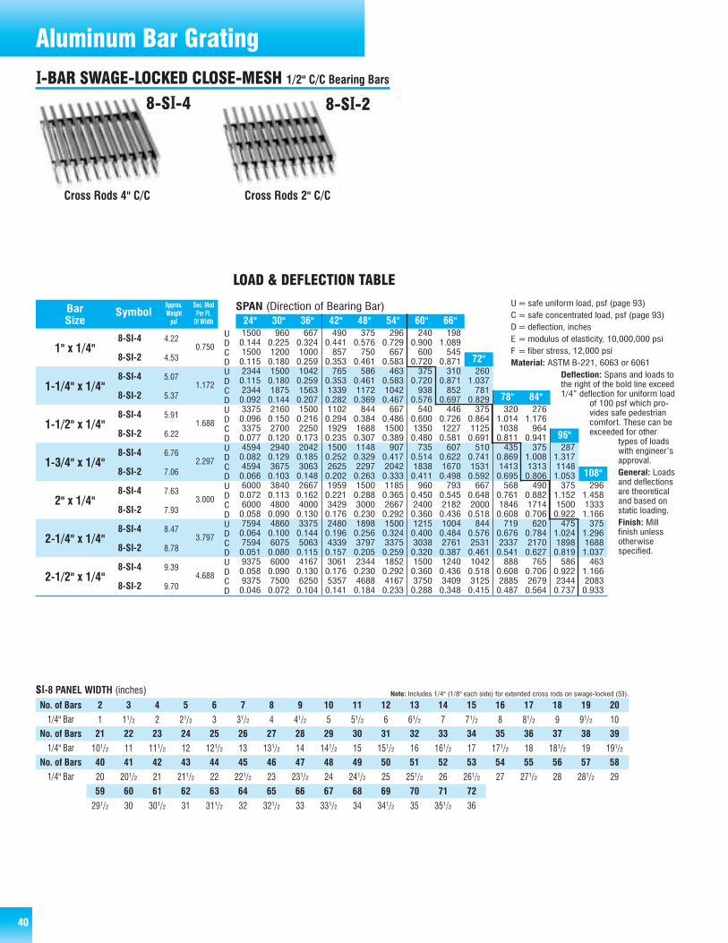
40
U=safe uniform load, psf (page 93)C= safe concentrated load, psf (page 93)D=deflection, inchesE =modulus of elasticity, 10,000,000 psiF = fiber stress, 12,000 psiMaterial: ASTM B-221, 6063 or 6061
Deflection: Spans and loads tothe right of the bold line exceed1/4” deflection for uniform load
of 100 psf which pro-vides safe pedestriancomfort. These can beexceeded for other
types of loadswith engineer’sapproval.General: Loadsand deflectionsare theoreticaland based on static loading.Finish: Mill finish unless otherwise specified.
1500 960 667 490 375 296 240 1980.144 0.225 0.324 0.441 0.576 0.729 0.900 1.0891500 1200 1000 857 750 667 600 5450.115 0.180 0.259 0.353 0.461 0.583 0.720 0.8712344 1500 1042 765 586 463 375 310 2600.115 0.180 0.259 0.353 0.461 0.583 0.720 0.871 1.0372344 1875 1563 1339 1172 1042 938 852 7810.092 0.144 0.207 0.282 0.369 0.467 0.576 0.697 0.8293375 2160 1500 1102 844 667 540 446 375 320 2760.096 0.150 0.216 0.294 0.384 0.486 0.600 0.726 0.864 1.014 1.1763375 2700 2250 1929 1688 1500 1350 1227 1125 1038 9640.077 0.120 0.173 0.235 0.307 0.389 0.480 0.581 0.691 0.811 0.9414594 2940 2042 1500 1148 907 735 607 510 435 375 2870.082 0.129 0.185 0.252 0.329 0.417 0.514 0.622 0.741 0.869 1.008 1.3174594 3675 3063 2625 2297 2042 1838 1670 1531 1413 1313 11480.066 0.103 0.148 0.202 0.263 0.333 0.411 0.498 0.592 0.695 0.806 1.0536000 3840 2667 1959 1500 1185 960 793 667 568 490 375 2960.072 0.113 0.162 0.221 0.288 0.365 0.450 0.545 0.648 0.761 0.882 1.152 1.4586000 4800 4000 3429 3000 2667 2400 2182 2000 1846 1714 1500 13330.058 0.090 0.130 0.176 0.230 0.292 0.360 0.436 0.518 0.608 0.706 0.922 1.1667594 4860 3375 2480 1898 1500 1215 1004 844 719 620 475 3750.064 0.100 0.144 0.196 0.256 0.324 0.400 0.484 0.576 0.676 0.784 1.024 1.2967594 6075 5063 4339 3797 3375 3038 2761 2531 2337 2170 1898 16880.051 0.080 0.115 0.157 0.205 0.259 0.320 0.387 0.461 0.541 0.627 0.819 1.0379375 6000 4167 3061 2344 1852 1500 1240 1042 888 765 586 4630.058 0.090 0.130 0.176 0.230 0.292 0.360 0.436 0.518 0.608 0.706 0.922 1.1669375 7500 6250 5357 4688 4167 3750 3409 3125 2885 2679 2344 20830.046 0.072 0.104 0.141 0.184 0.233 0.288 0.348 0.415 0.487 0.564 0.737 0.933
8-SI-4
8-SI-2
8-SI-4
8-SI-2
8-SI-4
8-SI-2
8-SI-4
8-SI-2
8-SI-4
8-SI-2
8-SI-4
8-SI-2
8-SI-4
8-SI-2
72"
78" 84"
96"
108"
Approx. Sec. ModBar Symbol Weight Per Ft.Size psf Of Width
1" x 1/4"
1-1/4" x 1/4"
1-1/2" x 1/4"
1-3/4" x 1/4"
2" x 1/4"
2-1/4" x 1/4"
2-1/2" x 1/4"
0.750
1.172
1.688
2.297
3.000
3.797
4.688
4.22
4.53
5.07
5.37
5.91
6.22
6.76
7.06
7.63
7.93
8.47
8.78
9.39
9.70
SPAN (Direction of Bearing Bar)
LOAD & DEFLECTION TABLE
UDCDUDCDUDCDUDCDUDCDUDCDUDCD
24" 30" 36" 42" 48" 54" 60" 66"
2 3 4 5 6 7 8 9 10 11 12 13 14 15 16 17 18 19 20
1 11/2 2 21/2 3 31/2 4 41/2 5 51/2 6 61/2 7 71/2 8 81/2 9 91/2 10
101/2 11 111/2 12 121/2 13 131/2 14 141/2 15 151/2 16 161/2 17 171/2 18 181/2 19 191/2
21 22 23 24 25 26 27 28 29 30 31 32 33 34 35 36 37 38 39
20 201/2 21 211/2 22 221/2 23 231/2 24 241/2 25 251/2 26 261/2 27 271/2 28 281/2 29
40 41 42 43 44 45 46 47 48 49 50 51 52 53 54 55 56 57 58
SII-8 PANEL WIDTH (inches)No. of Bars1/4" Bar
1/4" Bar
No. of Bars
1/4" Bar
No. of Bars
291/2 30 301/2 31 311/2 32 321/2 33 331/2 34 341/2 35 351/2 36
59 60 61 62 63 64 65 66 67 68 69 70 71 72
Note: Includes 1/4" (1/8" each side) for extended cross rods on swage-locked (SI).
40
Cross Rods 4" C/C Cross Rods 2" C/C
8-SII-4 8-SII-2
Aluminum Bar GratingII-BAR SWAGE-LOCKED CLOSE-MESH 1/2" C/C Bearing Bars
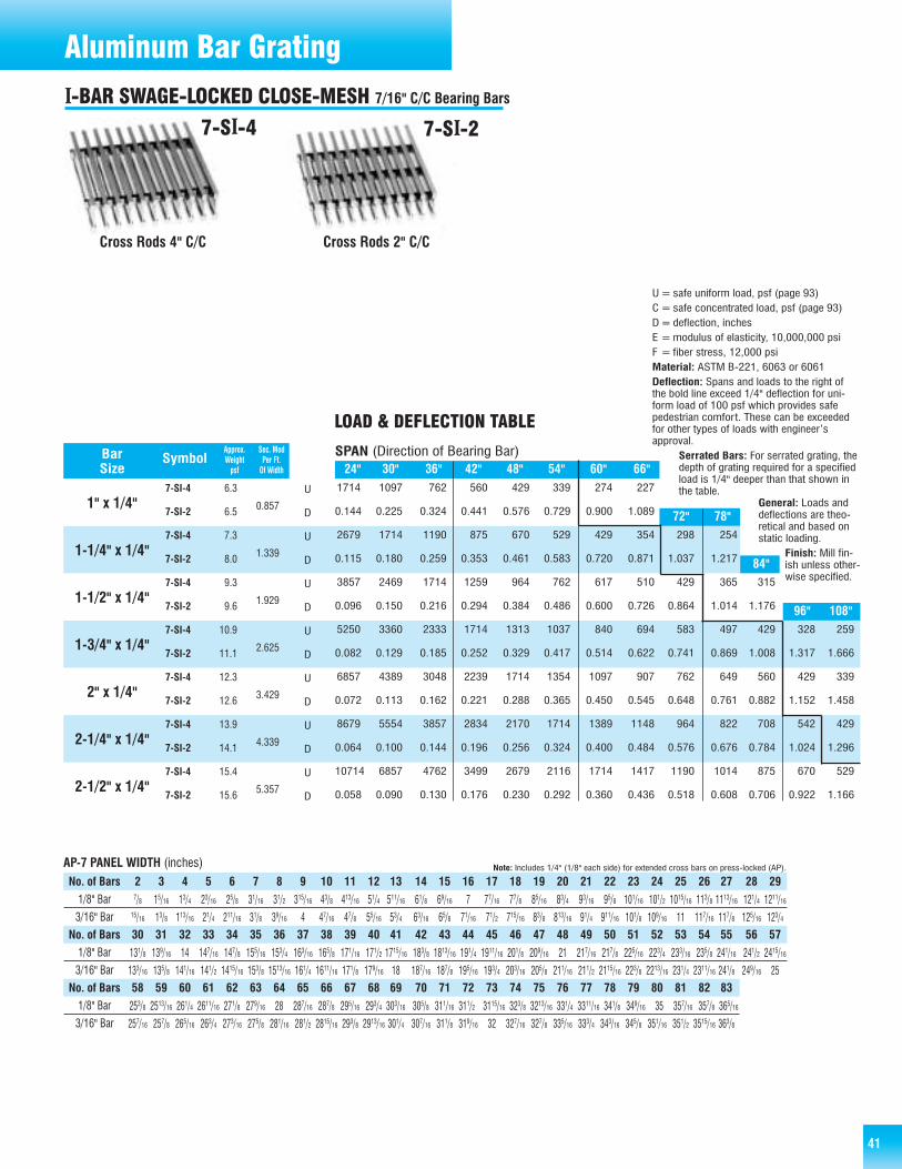
U=safe uniform load, psf (page 93)C= safe concentrated load, psf (page 93)D=deflection, inchesE =modulus of elasticity, 10,000,000 psiF = fiber stress, 12,000 psiMaterial: ASTM B-221, 6063 or 6061Deflection: Spans and loads to the right ofthe bold line exceed 1/4" deflection for uni-form load of 100 psf which provides safepedestrian comfort. These can be exceededfor other types of loads with engineer’sapproval.
Serrated Bars: For serrated grating, thedepth of grating required for a specified load is 1/4" deeper than that shown inthe table.
General: Loads anddeflections are theo-retical and based onstatic loading.
Finish: Mill fin-ish unless other-wise specified.
41
Cross Rods 4" C/C Cross Rods 2" C/C
7-SII-4 7-SII-2
Aluminum Bar GratingII-BAR SWAGE-LOCKED CLOSE-MESH 7/16" C/C Bearing Bars
1714 1097 762 560 429 339 274 227
0.144 0.225 0.324 0.441 0.576 0.729 0.900 1.089
2679 1714 1190 875 670 529 429 354 298 254
0.115 0.180 0.259 0.353 0.461 0.583 0.720 0.871 1.037 1.217
3857 2469 1714 1259 964 762 617 510 429 365 315
0.096 0.150 0.216 0.294 0.384 0.486 0.600 0.726 0.864 1.014 1.176
5250 3360 2333 1714 1313 1037 840 694 583 497 429 328 259
0.082 0.129 0.185 0.252 0.329 0.417 0.514 0.622 0.741 0.869 1.008 1.317 1.666
6857 4389 3048 2239 1714 1354 1097 907 762 649 560 429 339
0.072 0.113 0.162 0.221 0.288 0.365 0.450 0.545 0.648 0.761 0.882 1.152 1.458
8679 5554 3857 2834 2170 1714 1389 1148 964 822 708 542 429
0.064 0.100 0.144 0.196 0.256 0.324 0.400 0.484 0.576 0.676 0.784 1.024 1.296
10714 6857 4762 3499 2679 2116 1714 1417 1190 1014 875 670 529
0.058 0.090 0.130 0.176 0.230 0.292 0.360 0.436 0.518 0.608 0.706 0.922 1.166
7-SI-4
7-SI-2
7-SI-4
7-SI-2
7-SI-4
7-SI-2
7-SI-4
7-SI-2
7-SI-4
7-SI-2
7-SI-4
7-SI-2
7-SI-4
7-SI-2
24" 30" 36" 42" 48" 54" 60" 66"
96" 108"
72" 78"
84"
Approx. Sec. ModBar Symbol Weight Per Ft.Size psf Of Width
1" x 1/4"
1-1/4" x 1/4"
1-1/2" x 1/4"
1-3/4" x 1/4"
2" x 1/4"
2-1/4" x 1/4"
2-1/2" x 1/4"
0.857
1.339
1.929
2.625
3.429
4.339
5.357
6.3
6.5
7.3
8.0
9.3
9.6
10.9
11.1
12.3
12.6
13.9
14.1
15.4
15.6
SPAN (Direction of Bearing Bar)
LOAD & DEFLECTION TABLE
U
D
U
D
U
D
U
D
U
D
U
D
U
D
AP-7 PANEL WIDTH (inches) Note: Includes 1/4" (1/8" each side) for extended cross bars on press-locked (AP).
2 3 4 5 6 7 8 9 10 11 12 13 14 15 16 17 18 19 20 21 22 23 24 25 26 27 28 297/8 15/16 13/4 23/16 25/8 31/16 31/2 315/16 43/8 413/16 51/4 511/16 61/8 69/16 7 77/16 77/8 85/16 83/4 93/16 95/8 101/16 101/2 1015/16 113/8 1113/16 121/4 1211/16
15/16 13/8 113/16 21/4 211/16 31/8 39/16 4 47/16 47/8 55/16 53/4 63/16 65/8 71/16 71/2 715/16 83/8 813/16 91/4 911/16 101/8 109/16 11 117/16 117/8 125/16 123/430 31 32 33 34 35 36 37 38 39 40 41 42 43 44 45 46 47 48 49 50 51 52 53 54 55 56 57
131/8 139/16 14 147/16 147/8 155/16 153/4 163/16 165/8 171/16 171/2 1715/16 183/8 1813/16 191/4 1911/16 201/8 209/16 21 217/16 217/8 225/16 223/4 233/16 235/8 241/16 241/2 2415/16
133/16 135/8 141/16 141/2 1415/16 153/8 1513/16 161/4 1611/16 171/8 179/16 18 187/16 187/8 195/16 193/4 203/16 205/8 211/16 211/2 2115/16 223/8 2213/16 231/4 2311/16 241/8 249/16 2558 59 60 61 62 63 64 65 66 67 68 69 70 71 72 73 74 75 76 77 78 79 80 81 82 83
253/8 2513/16 261/4 2611/16 271/8 279/16 28 287/16 287/8 295/16 293/4 303/16 305/8 311/16
257/16 257/8 265/16 263/4 273/16 275/8 281/16 281/2 2815/16 293/8 2913/16 301/4 307/16 311/8 319/16 32 327/16 327/8 335/16 333/4 343/16 345/8 351/16 351/2 3515/16 363/8
No. of Bars1/8" Bar
3/16" Bar
1/8" Bar
3/16" Bar
No. of Bars
1/8" Bar
3/16" Bar
No. of Bars
311/2 3115/16 323/8 3213/16 331/4 3311/16 341/8 349/16 35 357/16 357/8 365/16
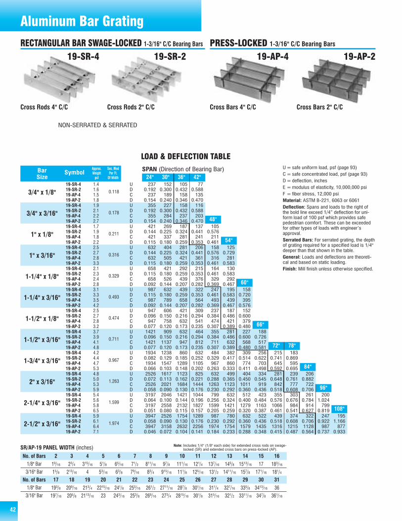
42 4242
Approx. Sec. ModBar Symbol Weight Per Ft.Size psf Of Width
237 152 105 770.192 0.300 0.432 0.588237 189 158 135
0.154 0.240 0.346 0.470355 227 158 116
0.192 0.300 0.432 0.588355 284 237 203
0.154 0.240 0.346 0.470421 269 187 137 105
0.144 0.225 0.324 0.441 0.576421 337 281 241 211
0.115 0.180 0.259 0.353 0.461632 404 281 206 158 125
0.144 0.225 0.324 0.441 0.576 0.729632 505 421 361 316 281
0.115 0.180 0.259 0.353 0.461 0.583658 421 292 215 164 130
0.115 0.180 0.259 0.353 0.461 0.583658 526 439 376 329 292
0.092 0.144 0.207 0.282 0.369 0.467987 632 439 322 247 195 158
0.115 0.180 0.259 0.353 0.461 0.583 0.720987 789 658 564 493 439 395
0.092 0.144 0.207 0.282 0.369 0.467 0.576947 606 421 309 237 187 152
0.096 0.150 0.216 0.294 0.384 0.486 0.600947 758 632 541 474 421 379
0.077 0.120 0.173 0.235 0.307 0.389 0.4801421 909 632 464 355 281 227 1880.096 0.150 0.216 0.294 0.384 0.486 0.600 0.7261421 1137 947 812 711 632 568 5170.077 0.120 0.173 0.235 0.307 0.389 0.480 0.5811934 1238 860 632 484 382 309 256 215 1830.082 0.129 0.185 0.252 0.329 0.417 0.514 0.622 0.741 0.8691934 1547 1289 1105 967 860 774 703 645 5950.066 0.103 0.148 0.202 0.263 0.333 0.411 0.498 0.592 0.6952526 1617 1123 825 632 499 404 334 281 239 2060.072 0.113 0.162 0.221 0.288 0.365 0.450 0.545 0.648 0.761 0.8822526 2021 1684 1444 1263 1123 1011 919 842 777 7220.058 0.090 0.130 0.176 0.230 0.292 0.360 0.436 0.518 0.608 0.7063197 2046 1421 1044 799 632 512 423 355 303 261 2000.064 0.100 0.144 0.196 0.256 0.324 0.400 0.484 0.576 0.676 0.784 1.0243197 2558 2132 1827 1599 1421 1279 1163 1066 984 914 7990.051 0.080 0.115 0.157 0.205 0.259 0.320 0.387 0.461 0.541 0.627 0.8193947 2526 1754 1289 987 780 632 522 439 374 322 247 1950.058 0.090 0.130 0.176 0.230 0.292 0.360 0.436 0.518 0.608 0.706 0.922 1.1663947 3158 2632 2256 1974 1754 1579 1435 1316 1215 1128 987 8770.046 0.072 0.104 0.141 0.184 0.233 0.288 0.348 0.415 0.487 0.564 0.737 0.933
19-SR-419-SR-219-AP-419-AP-219-SR-419-SR-219-AP-419-AP-219-SR-419-SR-219-AP-419-AP-219-SR-419-SR-219-AP-419-AP-219-SR-419-SR-219-AP-419-AP-219-SR-419-SR-219-AP-419-AP-219-SR-419-SR-219-AP-419-AP-219-SR-419-SR-219-AP-419-AP-219-SR-419-SR-219-AP-419-AP-219-SR-419-SR-219-AP-419-AP-219-SR-419-SR-219-AP-419-AP-219-SR-419-SR-219-AP-419-AP-2
24" 30" 36" 42"
72" 78"
48"
54"
60"
66"
84"
96"
108"
3/4" x 1/8"
3/4" x 3/16"
1" x 1/8"
1" x 3/16"
1-1/4" x 1/8"
1-1/4" x 3/16"
1-1/2" x 1/8"
1-1/2" x 3/16"
1-3/4" x 3/16"
2" x 3/16"
2-1/4" x 3/16"
2-1/2" x 3/16"
0.118
0.178
0.211
0.316
0.329
0.493
0.474
0.711
0.967
1.263
1.599
1.974
SPAN (Direction of Bearing Bar)
LOAD & DEFLECTION TABLE
UDCDUDCDUDCDUDCDUDCDUDCDUDCDUDCDUDCDUDCDUDCDUDCD
U=safe uniform load, psf (page 93)C= safe concentrated load, psf (page 93)D=deflection, inchesE =modulus of elasticity, 10,000,000 psiF = fiber stress, 12,000 psiMaterial: ASTM B-221, 6063 or 6061Deflection: Spans and loads to the right ofthe bold line exceed 1/4” deflection for uni-form load of 100 psf which provides safepedestrian comfort. These can be exceededfor other types of loads with engineer’sapproval.Serrated Bars: For serrated grating, the depthof grating required for a specified load is 1/4"deeper than that shown in the table.General: Loads and deflections are theoreti-cal and based on static loading.Finish: Mill finish unless otherwise specified.
Cross Rods 4" C/C Cross Rods 2" C/C Cross Bars 2" C/CCross Bars 4" C/C
19-SR-4 19-SR-2 19-AP-219-AP-4
Aluminum Bar Grating
SR/AP-19 PANEL WIDTH (inches)
1.41.61.51.81.92.12.22.71.71.91.82.22.52.72.83.32.12.32.42.83.13.33.54.22.52.72.83.23.73.94.14.84.24.44.75.34.85.05.35.95.45.65.86.55.96.16.47.1
Note: Includes 1/4" (1/8" each side) for extended cross rods on swage-locked (SR) and extended cross bars on press-locked (AP).
No. of Bars 2 3 4 5 6 7 8 9 10 11 12 13 14 15 161/8" Bar
3/16" Bar19/16 23/4 315/16 51/8 65/16 71/2 811/16 97/8 111/16 121/4 137/16 145/8 1513/16 17 183/16
15/8 213/16 4 53/16 63/8 79/16 83/4 915/16 111/8 125/16 131/2 1411/16 157/8 171/16 181/4
1/8" Bar
3/16" Bar193/8 209/16 213/4 2215/16 241/8 255/16 261/2 2711/16 287/8 301/16 311/4 327/16 335/8 3413/16 36
197/16 205/8 2113/16 23 243/16 253/8 269/16 273/4 2815/16 301/8 315/16 321/2 3311/16 347/8 361/16
No. of Bars 17 18 19 20 21 22 23 24 25 26 27 28 29 30 31
RECTANGULAR BAR SWAGE-LOCKED 1-3/16" C/C Bearing Bars PRESS-LOCKED 1-3/16" C/C Bearing Bars
NON-SERRATED & SERRATED

434343
300 192 133 980.192 0.300 0.432 0.588300 240 200 171
0.154 0.240 0.346 0.470450 288 200 147 113
0.192 0.300 0.432 0.588 0.768450 360 300 257 225
0.154 0.240 0.346 0.470 0.614533 341 237 174 133
0.144 0.225 0.324 0.441 0.576533 427 356 305 267
0.115 0.180 0.259 0.353 0.461800 512 356 261 200 158
0.144 0.225 0.324 0.441 0.576 0.729800 640 533 457 400 356
0.115 0.180 0.259 0.353 0.461 0.583833 533 370 272 208 165 133
0.115 0.180 0.259 0.353 0.461 0.583 0.720833 667 556 476 417 370 333
0.092 0.144 0.207 0.282 0.369 0.467 0.5761250 800 556 408 313 247 200 1650.115 0.180 0.259 0.353 0.461 0.583 0.720 0.8711250 1000 833 714 625 556 500 4550.092 0.144 0.207 0.282 0.369 0.467 0.576 0.6971200 768 533 392 300 237 192 1590.096 0.150 0.216 0.294 0.384 0.486 0.600 0.7261200 960 800 686 600 533 480 4360.077 0.120 0.173 0.235 0.307 0.389 0.480 0.5811800 1152 800 588 450 356 288 238 2000.096 0.150 0.216 0.294 0.384 0.486 0.600 0.726 0.8641800 1440 1200 1029 900 800 720 655 6000.077 0.120 0.173 0.235 0.307 0.389 0.480 0.581 0.6912450 1568 1089 800 613 484 392 324 272 2320.082 0.129 0.185 0.252 0.329 0.417 0.514 0.622 0.741 0.8692450 1960 1633 1400 1225 1089 980 891 817 7540.066 0.103 0.148 0.202 0.263 0.333 0.411 0.498 0.592 0.6953200 2048 1422 1045 800 632 512 423 356 303 2610.072 0.113 0.162 0.221 0.288 0.365 0.450 0.545 0.648 0.761 0.8823200 2560 2133 1829 1600 1422 1280 1164 1067 985 9140.058 0.090 0.130 0.176 0.230 0.292 0.360 0.436 0.518 0.608 0.7064050 2592 1800 1322 1013 800 648 536 450 383 331 253 2000.064 0.100 0.144 0.196 0.256 0.324 0.400 0.484 0.576 0.676 0.784 1.024 1.2964050 3240 2700 2314 2025 1800 1620 1473 1350 1246 1157 1013 9000.051 0.080 0.115 0.157 0.205 0.259 0.320 0.387 0.461 0.541 0.627 0.819 1.0375000 3200 2222 1633 1250 988 800 661 556 473 408 313 2470.058 0.090 0.130 0.176 0.230 0.292 0.360 0.436 0.518 0.608 0.706 0.922 1.1665000 4000 3333 2857 2500 2222 2000 1818 1667 1538 1429 1250 11110.046 0.072 0.104 0.141 0.184 0.233 0.288 0.348 0.415 0.487 0.564 0.737 0.933
15-SR-415-SR-215-AP-415-AP-215-SR-415-SR-215-AP-415-AP-215-SR-415-SR-215-AP-415-AP-215-SR-415-SR-215-AP-415-AP-215-SR-415-SR-215-AP-415-AP-215-SR-415-SR-215-AP-415-AP-215-SR-415-SR-215-AP-415-AP-215-SR-415-SR-215-AP-415-AP-215-SR-415-SR-215-AP-415-AP-215-SR-415-SR-215-AP-415-AP-215-SR-415-SR-215-AP-415-AP-215-SR-415-SR-215-AP-415-AP-21
24" 30" 36" 42"
96" 108"
48"
54"
60"
66"
72"
78"
84"
Approx. Sec. ModBar Symbol Weight Per Ft.Size psf Of Width
3/4" x 1/8"
3/4" x 3/16"
1" x 1/8"
1" x 3/16"
1-1/4" x 1/8"
1-1/4" x 3/16"
1-1/2" x 1/8"
1-1/2" x 3/16"
1-3/4" x 3/16"
2" x 3/16"
2-1/4" x 3/16"
2-1/2" x 3/16"
0.150
0.225
0.267
0.400
0.417
0.625
0.600
0.900
1.225
1.600
2.025
2.500
SPAN (Direction of Bearing Bar)
Cross Rods 4" C/C Cross Rods 2" C/C Cross Bars 2" C/CCross Bars 4" C/C
15-SR-4 15-SR-2 15-AP-215-AP-4
LOAD & DEFLECTION TABLE
UDCDUDCDUDCDUDCDUDCDUDCDUDCDUDCDUDCDUDCDUDCDUDCD
U=safe uniform load, psf (page 93)C= safe concentrated load, psf (page 93)D=deflection, inchesE =modulus of elasticity, 10,000,000 psiF = fiber stress, 12,000 psiMaterial: ASTM B-221, 6063 or 6061Deflection: Spans and loads to the right ofthe bold line exceed 1/4” deflection for uni-form load of 100 psf which provides safepedestrian comfort. These can be exceededfor other types of loads with engineer’sapproval.Serrated Bars: For serrated grating, the depthof grating required for a specified load is 1/4"deeper than that shown in the table.General: Loads and deflections are theoreti-cal and based on static loading.Finish: Mill finish unless otherwise specified.
Aluminum Bar Grating
1.71.91.82.12.32.82.73.22.12.42.32.63.13.33.43.92.62.82.93.33.84.04.35.03.13.33.43.84.54.85.05.75.35.55.76.46.06.26.47.16.76.97.27.87.47.87.98.5
SR/AP-15 PANEL WIDTH (inches) Note: Includes 1/4" (1/8" each side) for extended cross rods on swage-locked (SR) and extended cross bars on press-locked (AP).
2 3 4 5 6 7 8 9 10 11 12 13 14 15 16 17 18 19 20
15/16 21/4 33/16 41/8 51/16 6 615/16 77/8 813/16 93/4 1011/16 115/8 129/16 131/2 147/16 153/8 165/16 171/4 183/16
13/8 25/16 31/4 43/16 51/8 61/16 7 715/16 87/8 913/16 103/4 1111/16 125/8 139/16 141/2 157/16 163/8 175/16 181/4
191/8 201/16 21 2115/16 227/8 2313/16 243/4 2511/16 265/8 279/16 281/2 297/16 303/8 315/16 321/4 333/16 341/8 351/16 36
193/16 201/8 211/16 22 2215/16 237/8 2413/16 253/4 2611/16 275/8 289/16 291/2 307/16 313/8 325/16 331/4 343/16 351/8 361/16
21 22 23 24 25 26 27 28 29 30 31 32 33 34 35 36 37 38 39
No. of Bars1/8" Bar
3/16" Bar
1/8" Bar
3/16" Bar
No. of Bars
RECTANGULAR BAR SWAGE-LOCKED 15/16" C/C Bearing Bars PRESS-LOCKED 15/16" C/C Bearing Bars
NON-SERRATED & SERRATED
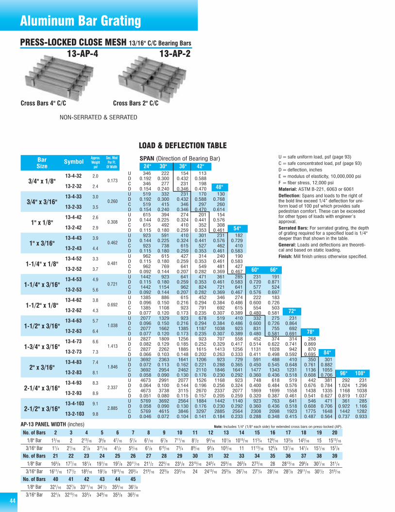
44
AP-13 PANEL WIDTH (inches)
346 222 154 1130.192 0.300 0.432 0.588346 277 231 198
0.154 0.240 0.346 0.470519 332 231 170 130
0.192 0.300 0.432 0.588 0.768519 415 346 297 260
0.154 0.240 0.346 0.470 0.614615 394 274 201 154
0.144 0.225 0.324 0.441 0.576615 492 410 352 308
0.115 0.180 0.259 0.353 0.461923 591 410 301 231 182
0.144 0.225 0.324 0.441 0.576 0.729923 738 615 527 462 410
0.115 0.180 0.259 0.353 0.461 0.583962 615 427 314 240 190
0.115 0.180 0.259 0.353 0.461 0.583962 769 641 549 481 427
0.092 0.144 0.207 0.282 0.369 0.4671442 923 641 471 361 285 231 1910.115 0.180 0.259 0.353 0.461 0.583 0.720 0.8711442 1154 962 824 721 641 577 5240.092 0.144 0.207 0.282 0.369 0.467 0.576 0.6971385 886 615 452 346 274 222 1830.096 0.150 0.216 0.294 0.384 0.486 0.600 0.7261385 1108 923 791 692 615 554 5030.077 0.120 0.173 0.235 0.307 0.389 0.480 0.5812077 1329 923 678 519 410 332 275 2310.096 0.150 0.216 0.294 0.384 0.486 0.600 0.726 0.8642077 1662 1385 1187 1038 923 831 755 6920.077 0.120 0.173 0.235 0.307 0.389 0.480 0.581 0.6912827 1809 1256 923 707 558 452 374 314 2680.082 0.129 0.185 0.252 0.329 0.417 0.514 0.622 0.741 0.8692827 2262 1885 1615 1413 1256 1131 1028 942 8700.066 0.103 0.148 0.202 0.263 0.333 0.411 0.498 0.592 0.6953692 2363 1641 1206 923 729 591 488 410 350 3010.072 0.113 0.162 0.221 0.288 0.365 0.450 0.545 0.648 0.761 0.8823692 2954 2462 2110 1846 1641 1477 1343 1231 1136 10550.058 0.090 0.130 0.176 0.230 0.292 0.360 0.436 0.518 0.608 0.7064673 2991 2077 1526 1168 923 748 618 519 442 381 292 2310.064 0.100 0.144 0.196 0.256 0.324 0.400 0.484 0.576 0.676 0.784 1.024 1.2964673 3738 3115 2670 2337 2077 1869 1699 1558 1438 1335 1168 10380.051 0.080 0.115 0.157 0.205 0.259 0.320 0.387 0.461 0.541 0.627 0.819 1.0375769 3692 2564 1884 1442 1140 923 763 641 546 471 361 2850.058 0.090 0.130 0.176 0.230 0.292 0.360 0.436 0.518 0.608 0.706 0.922 1.1665769 4615 3846 3297 2885 2564 2308 2098 1923 1775 1648 1442 12820.046 0.072 0.104 0.141 0.184 0.233 0.288 0.348 0.415 0.487 0.564 0.737 0.933
13-4-32
13-2-32
13-4-33
13-2-33
13-4-42
13-2-42
13-4-43
13-2-43
13-4-52
13-2-52
13-4-53
13-2-53
13-4-62
13-2-62
13-4-63
13-2-63
13-4-73
13-2-73
13-4-83
13-2-83
13-4-93
13-2-93
13-4-103
13-2-103
24" 30" 36" 42"
96" 108"
48"
54"
60" 66"
72"
78"
84"
Approx. Sec. ModBar Symbol Weight Per Ft.Size psf Of Width
3/4" x 1/8"
3/4" x 3/16"
1" x 1/8"
1" x 3/16"
1-1/4" x 1/8"
1-1/4" x 3/16"
1-1/2" x 1/8"
1-1/2" x 3/16"
1-3/4" x 3/16"
2" x 3/16"
2-1/4" x 3/16"
2-1/2" x 3/16"
0.173
0.260
0.308
0.462
0.481
0.721
0.692
1.038
1.413
1.846
2.337
2.885
2.0
2.4
3.0
3.5
2.6
2.9
3.9
4.4
3.3
3.7
4.9
5.6
3.8
4.3
5.7
6.4
6.6
7.3
7.4
8.1
8.3
8.9
9.1
9.8
SPAN (Direction of Bearing Bar)
LOAD & DEFLECTION TABLE
UDCDUDCDUDCDUDCDUDCDUDCDUDCDUDCDUDCDUDCDUDCDUDCD
U=safe uniform load, psf (page 93)C= safe concentrated load, psf (page 93)D=deflection, inchesE =modulus of elasticity, 10,000,000 psiF = fiber stress, 12,000 psiMaterial: ASTM B-221, 6063 or 6061Deflection: Spans and loads to the right ofthe bold line exceed 1/4” deflection for uni-form load of 100 psf which provides safepedestrian comfort. These can be exceededfor other types of loads with engineer’sapproval.Serrated Bars: For serrated grating, the depthof grating required for a specified load is 1/4"deeper than that shown in the table.General: Loads and deflections are theoreti-cal and based on static loading.Finish: Mill finish unless otherwise specified.
Cross Bars 4" C/C Cross Bars 2" C/C
13-AP-4 13-AP-2
Note: Includes 1/4" (1/8" each side) for extended cross bars on press-locked (AP).
2 3 4 5 6 7 8 9 10 11 12 13 14 15 16 17 18 19 20
13/16 2 213/16 35/8 47/16 51/4 61/16 67/8 711/16 81/2 95/16 101/8 1015/16 113/4 129/16 133/8 143/16 15 1513/16
11/4 21/16 27/8 311/16 41/2 55/16 61/8 615/16 73/4 89/16 93/8 103/16 11 1113/16 125/8 137/16 141/4 151/16 157/8
165/8 177/16 181/4 191/16 197/8 2011/16 211/2 225/16 231/8 2315/16 243/4 259/16 263/8 273/16 28 2813/16 295/8 307/16 311/4
1611/16 171/2 185/16 191/8 1915/16 203/4 219/16 223/8 233/16 24 2413/16 255/8 267/16 271/4 281/16 287/8 2911/16 301/2 315/16
21 22 23 24 25 26 27 28 29 30 31 32 33 34 35 36 37 38 39
321/16 327/8 3311/16 341/2 355/16 361/8
321/8 3215/16 333/4 349/16 353/8 363/16
40 41 42 43 44 45
No. of Bars1/8" Bar
3/16" Bar
1/8" Bar
3/16" Bar
No. of Bars
1/8" Bar
3/16" Bar
No. of Bars
Aluminum Bar GratingPRESS-LOCKED CLOSE MESH 13/16" C/C Bearing Bars
NON-SERRATED & SERRATED
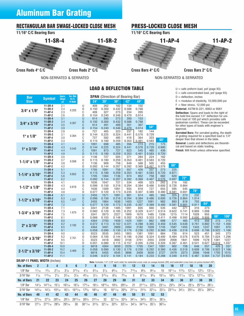
45
409 262 182 134 1020.192 0.300 0.432 0.588 0.768409 327 273 234 205
0.154 0.240 0.346 0.470 0.614614 393 273 200 153
0.192 0.300 0.432 0.588 0.768614 491 409 351 307
0.154 0.240 0.346 0.470 0.614727 465 323 237 182 144
0.144 0.225 0.324 0.441 0.576 0.729727 582 485 416 364 323
0.115 0.180 0.259 0.353 0.461 0.5831091 698 485 356 273 215 1750.144 0.225 0.324 0.441 0.576 0.729 0.9001091 873 727 623 545 485 4360.115 0.180 0.259 0.353 0.461 0.583 0.7201136 727 505 371 284 224 1820.115 0.180 0.259 0.353 0.461 0.583 0.7201136 909 758 649 568 505 4550.092 0.144 0.207 0.282 0.369 0.467 0.5761705 1091 758 557 426 337 273 2250.115 0.180 0.259 0.353 0.461 0.583 0.720 0.8711705 1364 1136 974 852 758 682 6200.092 0.144 0.207 0.282 0.369 0.467 0.576 0.6971636 1047 727 534 409 323 262 216 1820.096 0.150 0.216 0.294 0.384 0.486 0.600 0.726 0.8641636 1309 1091 935 818 727 655 595 5450.077 0.120 0.173 0.235 0.307 0.389 0.480 0.581 0.6912455 1571 1091 801 614 485 393 325 273 2320.096 0.150 0.216 0.294 0.384 0.486 0.600 0.726 0.864 1.0142455 1964 1636 1403 1227 1091 982 893 818 7550.077 0.120 0.173 0.235 0.307 0.389 0.480 0.581 0.691 0.8113341 2138 1485 1091 835 660 535 442 371 316 2730.082 0.129 0.185 0.252 0.329 0.417 0.514 0.622 0.741 0.869 1.0083341 2673 2227 1909 1670 1485 1336 1215 1114 1028 9550.066 0.103 0.148 0.202 0.263 0.333 0.411 0.498 0.592 0.695 0.8064364 2793 1939 1425 1091 862 698 577 485 413 356 273 2150.072 0.113 0.162 0.221 0.288 0.365 0.450 0.545 0.648 0.761 0.882 1.152 1.4584364 3491 2909 2494 2182 1939 1745 1587 1455 1343 1247 1091 9700.058 0.090 0.130 0.176 0.230 0.292 0.360 0.436 0.518 0.608 0.706 0.922 1.1665523 3535 2455 1803 1381 1091 884 730 614 523 451 345 2730.064 0.100 0.144 0.196 0.256 0.324 0.400 0.484 0.576 0.676 0.784 1.024 1.2965523 4418 3682 3156 2761 2455 2209 2008 1841 1699 1578 1381 12270.051 0.080 0.115 0.157 0.205 0.259 0.320 0.387 0.461 0.541 0.627 0.819 1.0376818 4364 3030 2226 1705 1347 1091 902 758 646 557 426 3370.058 0.090 0.130 0.176 0.230 0.292 0.360 0.436 0.518 0.608 0.706 0.922 1.1666818 5455 4545 3896 3409 3030 2727 2479 2273 2098 1948 1705 15150.046 0.072 0.104 0.141 0.184 0.233 0.288 0.348 0.415 0.487 0.564 0.737 0.933
11-SR-411-SR-211-AP-411-AP-211-SR-411-SR-211-AP-411-AP-211-SR-411-SR-211-AP-411-AP-211-SR-411-SR-211-AP-411-AP-211-SR-411-SR-211-AP-411-AP-211-SR-411-SR-211-AP-411-AP-211-SR-411-SR-211-AP-411-AP-211-SR-411-SR-211-AP-411-AP-211-SR-411-SR-211-AP-411-AP-211-SR-411-SR-211-AP-411-AP-211-SR-411-SR-211-AP-411-AP-211-SR-411-SR-211-AP-411-AP-2
24" 30" 36" 42" 48"
96" 108"
54"
60"
66"
72"
78"
84"
Approx. Sec. ModBar Symbol Weight Per Ft.Size psf Of Width
3/4" x 1/8"
3/4" x 3/16"
1" x 1/8"
1" x 3/16"
1-1/4" x 1/8"
1-1/4" x 3/16"
1-1/2" x 1/8"
1-1/2" x 3/16"
1-3/4" x 3/16"
2" x 3/16"
2-1/4" x 3/16"
2-1/2" x 3/16"
0.205
0.307
0.364
0.545
0.568
0.852
0.818
1.227
1.670
2.182
2.761
3.409
SPAN (Direction of Bearing Bar)
Cross Rods 4" C/C Cross Rods 2" C/C Cross Bars 2" C/CCross Bars 4" C/C
11-SR-4 11-SR-2 11-AP-211-AP-4
LOAD & DEFLECTION TABLE
UDCDUDCDUDCDUDCDUDCDUDCDUDCDUDCDUDCDUDCDUDCDUDCD
U=safe uniform load, psf (page 93)C= safe concentrated load, psf (page 93)D=deflection, inchesE =modulus of elasticity, 10,000,000 psiF = fiber stress, 12,000 psiMaterial: ASTM B-221, 6063 or 6061Deflection: Spans and loads to the right ofthe bold line exceed 1/4” deflection for uni-form load of 100 psf which provides safepedestrian comfort. These can be exceededfor other types of loads with engineer’sapproval.Serrated Bars: For serrated grating, the depthof grating required for a specified load is 1/4"deeper than that shown in the table.General: Loads and deflections are theoreti-cal and based on static loading.Finish: Mill finish unless otherwise specified.
SR/AP-11 PANEL WIDTH (inches)
2.12.42.32.63.13.43.53.92.83.13.03.34.14.34.44.93.53.73.84.25.15.35.66.24.14.34.44.86.16.36.57.27.17.37.58.18.08.28.59.19.09.29.5
10.110.010.210.411.1
Note: Includes 1/4" (1/8" each side) for extended cross rods on swage-locked (SR) and extended cross bars on press-locked (AP).
2 3 4 5 6 7 8 9 10 11 12 13 14 15 16 17 18 19 20
11/16 13/4 27/16 31/8 313/16 41/2 53/16 57/8 69/16 71/4 715/16 85/8 95/16 10 1011/16 113/8 121/16 123/4 137/16
11/8 113/16 21/2 33/16 37/8 49/16 51/4 515/16 65/8 75/16 8 811/16 93/8 101/16 103/4 117/16 121/8 1213/16 131/2
141/8 1413/16 151/2 163/16 167/8 179/16 181/4 1815/16 195/8 205/16 21 2111/16 223/8 231/16 233/4 247/16 251/8 2513/16 261/2
143/16 147/8 159/16 161/4 1615/16 175/8 185/16 19 1911/16 203/8 211/16 213/4 227/16 231/8 2313/16 241/2 253/16 257/8 269/16
21 22 23 24 25 26 27 28 29 30 31 32 33 34 35 36 37 38 39
273/16 277/8 289/16 291/4 2915/16 305/8 315/16 32 3211/16 333/8 341/16 343/4 357/16 361/8
271/4 2715/16 285/8 295/16 30 3011/16 313/8 321/16 323/4 337/16 341/8 3413/16 351/2 363/16
40 41 42 43 44 45 46 47 48 49 50 51 52 53
No. of Bars1/8" Bar
3/16" Bar
1/8" Bar
3/16" Bar
No. of Bars
1/8" Bar
3/16" Bar
No. of Bars
Aluminum Bar GratingRECTANGULAR BAR SWAGE-LOCKED CLOSE MESH11/16" C/C Bearing Bars
PRESS-LOCKED CLOSE MESH11/16" C/C Bearing Bars
NON-SERRATED & SERRATED NON-SERRATED & SERRATED
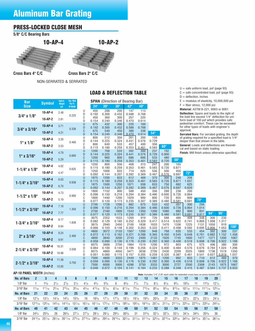
46
450 288 200 147 1130.192 0.300 0.432 0.588 0.768450 360 300 257 225
0.154 0.240 0.346 0.470 0.614675 432 300 220 169
0.192 0.300 0.432 0.588 0.768675 540 450 386 338
0.154 0.240 0.346 0.470 0.614800 512 356 261 200 158
0.144 0.225 0.324 0.441 0.576 0.729800 640 533 457 400 356
0.115 0.180 0.259 0.353 0.461 0.5831200 768 533 392 300 237 1920.144 0.225 0.324 0.441 0.576 0.729 0.9001200 960 800 686 600 533 4800.115 0.180 0.259 0.353 0.461 0.583 0.7201250 800 556 408 313 247 200 1650.115 0.180 0.259 0.353 0.461 0.583 0.720 0.8711250 1000 833 714 625 556 500 4550.092 0.144 0.207 0.282 0.369 0.467 0.576 0.6971875 1200 833 612 469 370 300 248 2080.115 0.180 0.259 0.353 0.461 0.583 0.720 0.871 1.0371875 1500 1250 1071 938 833 750 682 6250.092 0.144 0.207 0.282 0.369 0.467 0.576 0.697 0.8291800 1152 800 588 450 356 288 238 2000.096 0.150 0.216 0.294 0.384 0.486 0.600 0.726 0.8641800 1440 1200 1029 900 800 720 655 6000.077 0.120 0.173 0.235 0.307 0.389 0.480 0.581 0.6912700 1728 1200 882 675 533 432 357 300 2560.096 0.150 0.216 0.294 0.384 0.486 0.600 0.726 0.864 1.0142700 2160 1800 1543 1350 1200 1080 982 900 8310.077 0.120 0.173 0.235 0.307 0.389 0.480 0.581 0.691 0.8113675 2352 1633 1200 919 726 588 486 408 348 300 2300.082 0.129 0.185 0.252 0.329 0.417 0.514 0.622 0.741 0.869 1.008 1.3173675 2940 2450 2100 1838 1633 1470 1336 1225 1131 1050 9190.066 0.103 0.148 0.202 0.263 0.333 0.411 0.498 0.592 0.695 0.806 1.0534800 3072 2133 1567 1200 948 768 635 533 454 392 300 2370.072 0.113 0.162 0.221 0.288 0.365 0.450 0.545 0.648 0.761 0.882 1.152 1.4584800 3840 3200 2743 2400 2133 1920 1745 1600 1477 1371 1200 10670.058 0.090 0.130 0.176 0.230 0.292 0.360 0.436 0.518 0.608 0.706 0.922 1.1666075 3888 2700 1984 1519 1200 972 803 675 575 496 380 3000.064 0.100 0.144 0.196 0.256 0.324 0.400 0.484 0.576 0.676 0.784 1.024 1.2966075 4860 4050 3471 3038 2700 2430 2209 2025 1869 1736 1519 13500.051 0.080 0.115 0.157 0.205 0.259 0.320 0.387 0.461 0.541 0.627 0.819 1.0377500 4800 3333 2449 1875 1481 1200 992 833 710 612 469 3700.058 0.090 0.130 0.176 0.230 0.292 0.360 0.436 0.518 0.608 0.706 0.922 1.1667500 6000 5000 4286 3750 3333 3000 2727 2500 2308 2143 1875 16670.046 0.072 0.104 0.141 0.184 0.233 0.288 0.348 0.415 0.487 0.564 0.737 0.933
10-AP-4
10-AP-2
10-AP-4
10-AP-2
10-AP-4
10-AP-2
10-AP-4
10-AP-2
10-AP-4
10-AP-2
10-AP-4
10-AP-2
10-AP-4
10-AP-2
10-AP-4
10-AP-2
10-AP-4
10-AP-2
10-AP-4
10-AP-2
10-AP-4
10-AP-2
10-AP-4
10-AP-2
24" 30" 36" 42" 48"
84" 96"
54"
60"
66"
78"
108"
Approx. Sec. ModBar Symbol Weight Per Ft.Size psf Of Width
3/4" x 1/8"
3/4" x 3/16"
1" x 1/8"
1" x 3/16"
1-1/4" x 1/8"
1-1/4" x 3/16"
1-1/2" x 1/8"
1-1/2" x 3/16"
1-3/4" x 3/16"
2" x 3/16"
2-1/4" x 3/16"
2-1/2" x 3/16"
0.225
0.338
0.400
0.600
0.625
0.938
0.900
1.350
1.838
2.400
3.038
3.750
2.48
2.81
3.71
4.21
3.20
3.53
4.79
5.29
4.02
4.47
6.03
6.70
4.73
5.19
7.10
7.77
8.17
8.84
9.24
9.91
10.31
10.98
11.38
12.05
SPAN (Direction of Bearing Bar)
LOAD & DEFLECTION TABLE
UDCDUDCDUDCDUDCDUDCDUDCDUDCDUDCDUDCDUDCDUDCDUDCD
U=safe uniform load, psf (page 93)C= safe concentrated load, psf (page 93)D=deflection, inchesE =modulus of elasticity, 10,000,000 psiF = fiber stress, 12,000 psiMaterial: ASTM B-221, 6063 or 6061Deflection: Spans and loads to the right ofthe bold line exceed 1/4” deflection for uni-form load of 100 psf which provides safepedestrian comfort. These can be exceededfor other types of loads with engineer’sapproval.Serrated Bars: For serrated grating, the depthof grating required for a specified load is 1/4"deeper than that shown in the table.General: Loads and deflections are theoreti-cal and based on static loading.Finish: Mill finish unless otherwise specified.
Cross Bars 4" C/C Cross Bars 2" C/C
10-AP-4 10-AP-2
AP-10 PANEL WIDTH (inches) Note: Includes 1/4" (1/8" each side) for extended cross bars on press-locked (AP).
2 3 4 5 6 7 8 9 10 11 12 13 14 15 16 17 18 19 20
1 15/8 21/4 27/8 31/2 41/8 43/4 53/8 6 65/8 71/4 77/8 81/2 91/8 93/4 103/8 11 115/8 121/4
11/16 111/16 25/16 215/16 39/16 43/16 413/16 57/16 61/16 611/16 75/16 715/16 89/16 93/16 913/16 107/16 111/16 1111/16 125/16
127/8 131/2 141/8 143/4 153/8 16 165/8 171/4 177/8 181/2 191/8 193/4 203/8 21 215/8 221/4 227/8 231/2 241/8
1215/16 139/16 143/16 1413/16 157/16 161/16 1611/16 175/16 1715/16 189/16 193/16 1913/16 207/16 211/16 2111/16 225/16 2215/16 239/16 243/16
21 22 23 24 25 26 27 28 29 30 31 32 33 34 35 36 37 38 39
243/4 253/8 26 265/8 271/4 277/8 281/2 291/8 293/4 303/8 31 315/8 321/4 327/8 331/2 341/8 343/4 353/8 36
2413/16 257/16 261/16 2611/16 275/16 2715/16 289/16 293/16 2913/16 307/16 311/16 3111/16 325/16 3215/16 339/16 343/16 3413/16 357/16 361/16
40 41 42 43 44 45 46 47 48 49 50 51 52 53 54 55 56 57 58
No. of Bars1/8" Bar
3/16" Bar
1/8" Bar
3/16" Bar
No. of Bars
1/8" Bar
3/16" Bar
No. of Bars
Aluminum Bar GratingPRESS-LOCKED CLOSE MESH5/8" C/C Bearing Bars
72"
NON-SERRATED & SERRATED

47
563 360 250 184 1410.192 0.300 0.432 0.588 0.768563 450 375 321 281
0.154 0.240 0.346 0.470 0.614844 540 375 276 211 167
0.192 0.300 0.432 0.588 0.768 0.972844 675 563 482 422 375
0.154 0.240 0.346 0.470 0.614 0.7781000 640 444 327 250 198 1600.144 0.225 0.324 0.441 0.576 0.729 0.9001000 800 667 571 500 444 4000.115 0.180 0.259 0.353 0.461 0.583 0.7201500 960 667 490 375 296 240 1980.144 0.225 0.324 0.441 0.576 0.729 0.900 1.0891500 1200 1000 857 750 667 600 5450.115 0.180 0.259 0.353 0.461 0.583 0.720 0.8711563 1000 694 510 391 309 250 2070.115 0.180 0.259 0.353 0.461 0.583 0.720 0.8711563 1250 1042 893 781 694 625 5680.092 0.144 0.207 0.282 0.369 0.467 0.576 0.6972344 1500 1042 765 586 463 375 310 2600.115 0.180 0.259 0.353 0.461 0.583 0.720 0.871 1.0372344 1875 1563 1339 1172 1042 938 852 7810.092 0.144 0.207 0.282 0.369 0.467 0.576 0.697 0.8292250 1440 1000 735 563 444 360 298 250 2130.096 0.150 0.216 0.294 0.384 0.486 0.600 0.726 0.864 1.0142250 1800 1500 1286 1125 1000 900 818 750 6920.077 0.120 0.173 0.235 0.307 0.389 0.480 0.581 0.691 0.8113375 2160 1500 1102 844 667 540 446 375 320 2760.096 0.150 0.216 0.294 0.384 0.486 0.600 0.726 0.864 1.014 1.1763375 2700 2250 1929 1688 1500 1350 1227 1125 1038 9640.077 0.120 0.173 0.235 0.307 0.389 0.480 0.581 0.691 0.811 0.9414594 2940 2042 1500 1148 907 735 607 510 435 375 2870.082 0.129 0.185 0.252 0.329 0.417 0.514 0.622 0.741 0.869 1.008 1.3174594 3675 3063 2625 2297 2042 1838 1670 1531 1413 1313 11480.066 0.103 0.148 0.202 0.263 0.333 0.411 0.498 0.592 0.695 0.806 1.0536000 3840 2667 1959 1500 1185 960 793 667 568 490 375 2960.072 0.113 0.162 0.221 0.288 0.365 0.450 0.545 0.648 0.761 0.882 1.152 1.4586000 4800 4000 3429 3000 2667 2400 2182 2000 1846 1714 1500 13330.058 0.090 0.130 0.176 0.230 0.292 0.360 0.436 0.518 0.608 0.706 0.922 1.1667594 4860 3375 2480 1898 1500 1215 1004 844 719 620 475 3750.064 0.100 0.144 0.196 0.256 0.324 0.400 0.484 0.576 0.676 0.784 1.024 1.2967594 6075 5063 4339 3797 3375 3038 2761 2531 2337 2170 1898 16880.051 0.080 0.115 0.157 0.205 0.259 0.320 0.387 0.461 0.541 0.627 0.819 1.0379375 6000 4167 3061 2344 1852 1500 1240 1042 888 765 586 4630.058 0.090 0.130 0.176 0.230 0.292 0.360 0.436 0.518 0.608 0.706 0.922 1.1669375 7500 6250 5357 4688 4167 3750 3409 3125 2885 2679 2344 20830.046 0.072 0.104 0.141 0.184 0.233 0.288 0.348 0.415 0.487 0.564 0.737 0.933
8-SR-48-SR-28-AP-48-AP-28-SR-48-SR-28-AP-48-AP-28-SR-48-SR-28-AP-48-AP-28-SR-48-SR-28-AP-48-AP-28-SR-48-SR-28-AP-48-AP-28-SR-48-SR-28-AP-48-AP-28-SR-48-SR-28-AP-48-AP-28-SR-48-SR-28-AP-48-AP-28-SR-48-SR-28-AP-48-AP-28-SR-48-SR-28-AP-48-AP-28-SR-48-SR-28-AP-48-AP-28-SR-48-SR-28-AP-48-AP-2
24" 30" 36" 42" 48"
60"
66"
72"
78"
84"
96"
108"
54"
Approx. Sec. ModBar Symbol Weight Per Ft.Size psf Of Width
3/4" x 1/8"
3/4" x 3/16"
1" x 1/8"
1" x 3/16"
1-1/4" x 1/8"
1-1/4" x 3/16"
1-1/2" x 1/8"
1-1/2" x 3/16"
1-3/4" x 3/16"
2" x 3/16"
2-1/4" x 3/16"
2-1/2" x 3/16"
0.281
0.422
0.500
0.750
0.781
1.172
1.125
1.688
2.297
3.000
3.797
4.688
SPAN (Direction of Bearing Bar)
SR/AP-8 PANEL WIDTH (inches)
LOAD & DEFLECTION TABLE
UDCDUDCDUDCDUDCDUDCDUDCDUDCDUDCDUDCDUDCDUDCDUDCD
U=safe uniform load, psf (page 93)C= safe concentrated load, psf (page 93)D=deflection, inchesE =modulus of elasticity, 10,000,000 psiF = fiber stress, 12,000 psiMaterial: ASTM B-221, 6063 or 6061Deflection: Spans and loads to the right ofthe bold line exceed 1/4” deflection for uni-form load of 100 psf which provides safepedestrian comfort. These can be exceededfor other types of loads with engineer’sapproval.Serrated Bars: For serrated grating, the depth
of grating required for a specifiedload is 1/4" deeper than that shown inthe table.General: Loads and deflections aretheoretical and based on static load-ing.Finish: Mill finish unless otherwisespecified.
Cross Rods 4" C/C Cross Rods 2" C/C Cross Bars 2" C/CCross Bars 4" C/C
8-SR-4 8-SR-2 8-AP-28-AP-4
2.93.03.13.34.24.44.55.03.74.03.94.25.65.85.86.34.84.94.95.36.97.17.38.05.65.85.86.28.28.48.79.39.59.8
10.010.710.911.111.312.012.212.412.713.313.513.814.014.7
Note: Includes 1/4" (1/8" each side) for extended cross rods on swage-locked (SR) and extended cross bars on press-locked (AP).
2 3 4 5 6 7 8 9 10 11 12 13 14 15 16 17 18 19 20 21 22 23 24 25 26 27 28 297/8 13/8 17/8 23/8 27/8 33/8 37/8 43/8 47/8 53/8 57/8 63/8 67/8 73/8 77/8 83/8 87/8 93/8 97/8 103/8 107/8 113/8 117/8 123/8 127/8 133/8 137/8 143/8
15/16 17/16 115/16 27/16 215/16 37/16 315/16 47/16 415/16 57/16 515/16 67/16 615/16 77/16 715/16 87/16 815/16 97/16 915/16 107/16 1015/16 117/16 1115/16 127/16 1215/16 137/16 1315/16 147/1630 31 32 33 34 35 36 37 38 39 40 41 42 43 44 45 46 47 48 49 50 51 52 53 54 55 56 57
147/8 153/8 157/8 163/8 167/8 173/8 177/8 183/8 187/8 193/8 197/8 203/8 207/8 213/8 217/8 223/8 227/8 233/8 237/8 243/8 247/8 253/8 257/8 263/8 267/8 273/8 277/8 283/8
1415/16 157/16 1515/16 167/16 1615/16 177/16 1715/16 187/16 1815/16 197/16 1915/16 207/16 2015/16 217/16 2115/16 227/16 2215/16 237/16 2315/16 247/16 2415/16 257/16 2515/16 267/16 2615/16 277/16 2715/16 287/1658 59 60 61 62 63 64 65 66 67 68 69 70 71 72
287/8 293/8 297/8 303/8 307/8 313/8 317/8 323/8 327/8 333/8 337/8 343/8 347/8 353/8 357/8
2815/16 297/16 2915/16 307/16 3015/16 317/16 3115/16 327/16 3215/16 337/16 3315/16 347/16 3415/16 357/16 3515/16
No. of Bars1/8" Bar
3/16" Bar
1/8" Bar
3/16" Bar
No. of Bars
1/8" Bar
3/16" Bar
No. of Bars
Aluminum Bar GratingRECTANGULAR BAR SWAGE-LOCKED CLOSE MESH1/2" Center to Center of Bearing Bars
PRESS-LOCKED CLOSE MESH1/2" Center to Center of Bearing Bars
NON-SERRATED & SERRATED NON-SERRATED & SERRATED

48 48
643 411 286 210 1610.192 0.300 0.432 0.588 0.768643 514 429 367 321
0.154 0.240 0.346 0.470 0.614964 617 429 315 241 190
0.192 0.300 0.432 0.588 0.768 0.972964 771 643 551 482 429
0.154 0.240 0.346 0.470 0.614 0.7781143 731 508 373 286 226 1830.144 0.225 0.324 0.441 0.576 0.729 0.9001143 914 762 653 571 508 4570.115 0.180 0.259 0.353 0.461 0.583 0.7201714 1097 762 560 429 339 274 2270.144 0.225 0.324 0.441 0.576 0.729 0.900 1.0891714 1371 1143 980 857 762 686 6230.115 0.180 0.259 0.353 0.461 0.583 0.720 0.8711786 1143 794 583 446 353 286 2360.115 0.180 0.259 0.353 0.461 0.583 0.720 0.8711786 1429 1190 1020 893 794 714 6490.092 0.144 0.207 0.282 0.369 0.467 0.576 0.6972679 1714 1190 875 670 529 429 354 298 2540.115 0.180 0.259 0.353 0.461 0.583 0.720 0.871 1.037 1.2172679 2143 1786 1531 1339 1190 1071 974 893 8240.092 0.144 0.207 0.282 0.369 0.467 0.576 0.697 0.829 0.9732571 1646 1143 840 643 508 411 340 286 2430.096 0.150 0.216 0.294 0.384 0.486 0.600 0.726 0.864 1.0142571 2057 1714 1469 1286 1143 1029 935 857 7910.077 0.120 0.173 0.235 0.307 0.389 0.480 0.581 0.691 0.8113857 2469 1714 1259 964 762 617 510 429 365 3150.096 0.150 0.216 0.294 0.384 0.486 0.600 0.726 0.864 1.014 1.1763857 3086 2571 2204 1929 1714 1543 1403 1286 1187 11020.077 0.120 0.173 0.235 0.307 0.389 0.480 0.581 0.691 0.811 0.9415250 3360 2333 1714 1313 1037 840 694 583 497 429 328 2590.082 0.129 0.185 0.252 0.329 0.417 0.514 0.622 0.741 0.869 1.008 1.317 1.6665250 4200 3500 3000 2625 2333 2100 1909 1750 1615 1500 1313 11670.066 0.103 0.148 0.202 0.263 0.333 0.411 0.498 0.592 0.695 0.806 1.053 1.3336857 4389 3048 2239 1714 1354 1097 907 762 649 560 429 3390.072 0.113 0.162 0.221 0.288 0.365 0.450 0.545 0.648 0.761 0.882 1.152 1.4586857 5486 4571 3918 3429 3048 2743 2494 2286 2110 1959 1714 15240.058 0.090 0.130 0.176 0.230 0.292 0.360 0.436 0.518 0.608 0.706 0.922 1.1668679 5554 3857 2834 2170 1714 1389 1148 964 822 708 542 4290.064 0.100 0.144 0.196 0.256 0.324 0.400 0.484 0.576 0.676 0.784 1.024 1.2968679 6943 5786 4959 4339 3857 3471 3156 2893 2670 2480 2170 19290.051 0.080 0.115 0.157 0.205 0.259 0.320 0.387 0.461 0.541 0.627 0.819 1.03710714 6857 4762 3499 2679 2116 1714 1417 1190 1014 875 670 5290.058 0.090 0.130 0.176 0.230 0.292 0.360 0.436 0.518 0.608 0.706 0.922 1.16610714 8571 7143 6122 5357 4762 4286 3896 3571 3297 3061 2679 23810.046 0.072 0.104 0.141 0.184 0.233 0.288 0.348 0.415 0.487 0.564 0.737 0.933
7-SR-47-SR-27-AP-47-AP-27-SR-47-SR-27-AP-47-AP-27-SR-47-SR-27-AP-47-AP-27-SR-47-SR-27-AP-47-AP-27-SR-47-SR-27-AP-47-AP-27-SR-47-SR-27-AP-47-AP-27-SR-47-SR-27-AP-47-AP-27-SR-47-SR-27-AP-47-AP-27-SR-47-SR-27-AP-47-AP-27-SR-47-SR-27-AP-47-AP-27-SR-47-SR-27-AP-47-AP-27-SR-47-SR-27-AP-47-AP-2
24" 30" 36" 42" 48"
96" 108"
72" 78"
60"
54"
66"
84"
Approx. Sec. ModBar Symbol Weight Per Ft.Size psf Of Width
3/4" x 1/8"
3/4" x 3/16"
1" x 1/8"
1" x 3/16"
1-1/4" x 1/8"
1-1/4" x 3/16"
1-1/2" x 1/8"
1-1/2" x 3/16"
1-3/4" x 3/16"
2" x 3/16"
2-1/4" x 3/16"
2-1/2" x 3/16"
0.321
0.482
0.571
0.857
0.893
1.339
1.286
1.929
2.625
3.429
4.339
5.357
3.23.53.33.74.85.05.15.84.24.54.44.76.36.56.67.15.35.55.66.07.38.08.39.06.36.56.57.09.39.69.8
10.510.911.111.311.912.312.612.813.913.914.114.315.015.415.615.916.5
SPAN (Direction of Bearing Bar)
LOAD & DEFLECTION TABLE
UDCDUDCDUDCDUDCDUDCDUDCDUDCDUDCDUDCDUDCDUDCDUDCD
U=safe uniform load, psf (page 93)C= safe concentrated load, psf (page 93)D=deflection, inchesE =modulus of elasticity, 10,000,000 psiF = fiber stress, 12,000 psiMaterial: ASTM B-221, 6063 or 6061Deflection: Spans and loads to the right ofthe bold line exceed 1/4" deflection for uni-form load of 100 psf which provides safepedestrian comfort. These can be exceededfor other types of loads with engineer’sapproval.Serrated Bars: For serrated grating, the depthof grating required for a specified load is 1/4"
deeper than that shown in the table.General: Loads and deflections aretheoretical and based on static loading.Finish: Mill finish unless otherwisespecified.
AP-7 PANEL WIDTH (inches) Note: Includes 1/4" (1/8" each side) for extended cross bars on press-locked (AP).
2 3 4 5 6 7 8 9 10 11 12 13 14 15 16 17 18 19 20 21 22 23 24 25 26 27 28 2913/16 11/4 111/16 21/8 29/16 3 37/16 37/8 45/16 43/4 53/16 55/8 61/16 61/2 615/16 73/8 713/16 81/4 811/16 91/8 99/16 10 107/16 107/8 115/16 113/4 123/16 125/87/8 15/16 13/4 23/16 25/8 31/16 31/2 315/16 43/8 413/16 51/4 511/16 61/8 69/16 7 77/16 77/8 85/16 83/4 93/16 95/8 101/16 101/2 1015/16 113/8 1113/16 121/4 1211/1630 31 32 33 34 35 36 37 38 39 40 41 42 43 44 45 46 47 48 49 50 51 52 53 54 55 56 57
131/16 131/2 1315/16 143/8 1413/16 151/4 1511/16 161/8 169/16 17 177/16 177/8 185/16 183/4 193/16 195/8 201/16 201/2 2015/16 213/8 2113/16 221/4 2211/16 231/8 239/16 24 247/16 247/8
131/8 139/16 14 147/16 147/8 155/16 153/4 163/16 165/8 171/16 171/2 1715/16 183/8 1813/16 191/4 1911/16 201/8 209/16 21 217/16 217/8 225/16 223/4 233/16 235/8 241/16 241/2 2415/1658 59 60 61 62 63 64 65 66 67 68 69 70 71 72 73 74 75 76 77 78 79 80 81 82 83
255/16 253/4 263/16 265/8 271/16 271/2 2715/16 283/8 2813/16 291/4 2911/16 301/8 309/16 31 317/16 317/8 325/16 323/4 333/16 335/8 341/16 341/2 3415/16 353/8 3513/16 361/4
253/8 2513/16 261/4 2611/16 271/8 279/16 28 287/16 287/8 295/16 293/4 303/16 305/8 311/16 311/2 3115/16 323/8 3213/16 331/4 3311/16 341/8 349/16 35 357/16 357/8 365/16
No. of Bars1/8" Bar
3/16" Bar
1/8" Bar
3/16" Bar
No. of Bars
1/8" Bar
3/16" Bar
No. of Bars
Cross Bars 2" C/CCross Bars 4" C/C
7-AP-27-AP-4
PRESS-LOCKED CLOSE MESH7/16" C/C Bearing Bars
Aluminum Bar Grating
NON-SERRATED & SERRATED
Cross Rods 4" C/C Cross Rods 2" C/C
7-SR-4 7-SR-2
RECTANGULAR BAR SWAGE-LOCKED CLOSE MESH7/16" Center to Center of Bearing Bars
NON-SERRATED & SERRATED

49
U=safe uniform load, psfC= safe concentrated load, psfD=deflection, inchesE =modulus of elasticity, 10,000,000 psiF = fiber stress, 10,000 psiMaterial: ASTM B-221—DUO-GRIP andbanding shall be extruded aluminum alloy
6063-T6Deflection: Spans and loads to theright of the bold line exceed 1/4”deflection for uniform load of 100 psf
which provides safe pedes-trian comfort. These can beexceeded for other types ofloads with engineer’s
approval.General: Loads anddeflections are theo-retical and based on
static loading.Finish:Mill finishunlessotherwisespecified.
49
435 278 193 142 109 860.115 0.180 0.259 0.353 0.461 0.583435 348 290 249 218 193
0.092 0.144 0.207 0.282 0.368 0.466760 486 338 248 190 150 122
0.089 0.138 0.199 0.271 0.354 0.448 0.553760 608 507 434 380 338 304
0.071 0.111 0.159 0.217 0.283 0.359 0.4431247 798 554 407 312 246 199 165 1390.075 0.117 0.169 0.230 0.301 0.381 0.470 0.569 0.6771247 997 831 712 623 554 499 453 4160.060 0.094 0.135 0.184 0.241 0.304 0.376 0.455 0.5411863 1193 828 608 466 368 298 246 207 1760.064 0.100 0.143 0.195 0.255 0.323 0.398 0.482 0.573 0.6731863 1491 1242 1065 932 828 745 678 621 5730.051 0.080 0.115 0.156 0.204 0.258 0.319 0.385 0.459 0.5382390 1530 1062 780 598 472 382 316 266 226 1950.055 0.087 0.125 0.170 0.222 0.280 0.346 0.419 0.499 0.585 0.6792390 1912 1593 1366 1195 1062 956 869 797 735 6830.044 0.069 0.100 0.136 0.177 0.224 0.277 0.335 0.399 0.468 0.5433463 2217 1539 1131 866 684 554 458 385 328 283 216 1710.051 0.079 0.114 0.155 0.203 0.256 0.317 0.383 0.456 0.535 0.621 0.811 1.0263463 2771 2309 1979 1732 1539 1385 1259 1154 1066 990 866 7700.041 0.063 0.091 0.124 0.162 0.205 0.253 0.307 0.365 0.428 0.496 0.648 0.8214130 2643 1836 1349 1033 816 661 546 459 391 337 258 2040.045 0.071 0.102 0.139 0.181 0.230 0.284 0.343 0.408 0.479 0.556 0.726 0.9194130 3304 2753 2360 2065 1836 1652 1502 1377 1271 1180 1033 9180.036 0.057 0.082 0.111 0.145 0.184 0.227 0.274 0.327 0.383 0.445 0.581 0.7354835 3094 2149 1579 1209 955 774 639 537 458 395 302 2390.041 0.064 0.093 0.126 0.165 0.208 0.257 0.311 0.370 0.434 0.504 0.658 0.8334835 3868 3223 2763 2418 2149 1934 1758 1612 1488 1381 1209 10740.033 0.051 0.074 0.101 0.132 0.167 0.206 0.249 0.296 0.348 0.403 0.526 0.666
DG-075
DG-100
DG-125
DG-150
DG-175
DG-200
DG-225
DG-250
96" 108"
66" 72"
60"
Per Ft. Of Width
0.261
0.456
0.748
1.118
1.434
2.078
2.478
2.901
0.136
0.309
0.597
1.053
1.553
2.461
3.277
4.232
2.5
3.1
3.6
4.3
4.6
5.3
5.5
5.7
SPANTABLE OF SAFE SPANS
UDCDUDCDUDCDUDCDUDCDUDCDUDCDUDCD
Rectangular Punched Unpunched Square Punched
A Duo-Grip™ grating panel consists of 6" wide planks of extruded alu-minum, welded to each other to form panels. Panel ends have an
extruded aluminum end bar welded in place. Grating is availableunpunched or punched in one of the standard patterns.
SymbolDuo-GripDepth
84"
78"
Approx.Weightpsf
Sec.Mod.
Mom. ofInt.
Aluminum Grating
3/4"
1"
1-1/4"
1-1/2"
1-3/4"
2"
2-1/4"
2-1/2"
24" 30" 36" 42" 48" 54"
DUO-GRIP™ EXTRUDED
Duo-Grip™ Planking, a one-piece extruded 26' long plank (standard),is available only from AMICO-Klemp® and has an exceptional strength andstiffness-to-weight ratio due to its integral I-beam ribs. It is available ineither unpunched, square punched or rectangular punched styles to suitlighting and ventilation considerations. The 6" wide panels are weldedtogether to form the desired panel width and an extruded aluminum endbar is welded into place. The design provides a surer walking surface foradditional safety.

50
Riveted GratingRiveted Bar Grating is the first choice by many engineers for many appli-cations. Compared to welded or swaged-locked grating, riveted has agreater load carrying capacity for the same span and depth of grating.Reticulated bars, riveted to the bearing bars increase resistance to buck-ling caused by vehicular loading conditions.
AMICO-Klemp® riveted carbon steel and aluminum gratings utilize riv-ets which are individually cold-pressed using hydraulically and mechani-cally operated riveting tools. Thus, the bearing bars and reticulated barsare sealed together as a high-strength joint, freeing the grating from theresidual stresses that cause warp and joint failures.
It is unparalleled where rolling stock and wheeled equipment are used,especially those with casters. The reticulated bars present a smoothersurface for this traffic. It is very popular for use as flooring, ramps, docksand other surfaces and it is ideally suited for walkways because of itsadded walking comfort.
AMICO-Klemp® can match your existing riveted grating when you arereplacing or expanding your installation. On special order, heavy-duty barsizes and/or widths greater than shown are also available.
18-R-7 18-R-3
12-R-7 12-R-3
STEEL & ALUMINUM RIVETED GRATING
Note: Spacing for riveted grating is inside to inside of bearing bars.
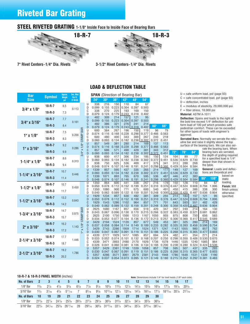
51
18-R-7
18-R-3
18-R-7
18-R-3
18-R-7
18-R-3
18-R-7
18-R-3
18-R-7
18-R-3
18-R-7
18-R-3
18-R-7
18-R-3
18-R-7
18-R-3
18-R-7
18-R-3
18-R-7
18-R-3
18-R-7
18-R-3
18-R-7
18-R-3
96" 108"
Approx. Sec. ModBar Symbol Weight Per Ft.Size psf Of Width
3/4" x 1/8"
3/4" x 3/16"
1" x 1/8"
1" x 3/16"
1-1/4" x 1/8"
1-1/4" x 3/16"
1-1/2" x 1/8"
1-1/2" x 3/16"
1-3/4" x 3/16"
2" x 3/16"
2-1/4" x 3/16"
2-1/2" x 3/16"
0.113
0.161
0.200
0.286
0.313
0.446
0.450
0.643
0.875
1.143
1.446
1.786
6.5
7.3
7.7
8.4
7.5
8.3
9.2
9.9
8.6
9.4
10.7
11.4
10.7
11.7
13.2
14.2
14.7
15.7
16.2
17.2
17.7
18.7
19.2
20.2
LOAD & DEFLECTION TABLE
UDCDUDCDUDCDUDCDUDCDUDCDUDCDUDCDUDCDUDCDUDCDUDCD
3/4" x 1/8" CRIMP BAR
1" x 1/8" CRIMP BAR
338 216 150 110 84 670.099 0.155 0.223 0.304 0.397 0.503338 270 225 193 169 150
0.079 0.124 0.179 0.243 0.318 0.402482 309 214 157 121 95
0.099 0.155 0.223 0.304 0.397 0.503482 386 321 276 241 214
0.079 0.124 0.179 0.243 0.318 0.402600 384 267 196 150 119 96 79
0.074 0.116 0.168 0.228 0.298 0.377 0.466 0.563600 480 400 343 300 267 240 218
0.060 0.093 0.134 0.182 0.238 0.302 0.372 0.451857 549 381 280 214 169 137 113
0.074 0.116 0.168 0.228 0.298 0.377 0.466 0.563857 686 571 490 429 381 343 312
0.060 0.093 0.134 0.182 0.238 0.302 0.372 0.451938 600 417 306 234 185 150 124 104 89 77
0.060 0.093 0.134 0.182 0.238 0.302 0.372 0.451 0.536 0.629 0.730938 750 625 536 469 417 375 341 313 288 268
0.048 0.074 0.107 0.146 0.191 0.241 0.298 0.360 0.429 0.504 0.5841339 857 595 437 335 265 214 177 149 127 1090.060 0.093 0.134 0.182 0.238 0.302 0.372 0.451 0.536 0.629 0.7301339 1071 893 765 670 595 536 487 446 412 3830.048 0.074 0.107 0.146 0.191 0.241 0.298 0.360 0.429 0.504 0.5841350 864 600 441 338 267 216 179 150 128 110 84 670.050 0.078 0.112 0.152 0.199 0.251 0.310 0.376 0.447 0.524 0.608 0.794 1.0061350 1080 900 771 675 600 540 491 450 415 386 338 3000.040 0.062 0.089 0.122 0.159 0.201 0.248 0.300 0.358 0.420 0.487 0.636 0.8041929 1234 857 630 482 381 309 255 214 183 157 121 950.050 0.078 0.112 0.152 0.199 0.251 0.310 0.376 0.447 0.524 0.608 0.794 1.0061929 1543 1286 1102 964 857 771 701 643 593 551 482 4290.040 0.062 0.089 0.122 0.159 0.201 0.248 0.300 0.358 0.420 0.487 0.636 0.8042625 1680 1167 857 656 519 420 347 292 249 214 164 1300.043 0.067 0.096 0.130 0.170 0.215 0.266 0.322 0.383 0.450 0.521 0.681 0.8622625 2100 1750 1500 1313 1167 1050 955 875 808 750 656 5830.034 0.053 0.077 0.104 0.136 0.172 0.213 0.257 0.306 0.360 0.417 0.545 0.6893429 2194 1524 1120 857 677 549 453 381 325 280 214 1690.037 0.058 0.084 0.114 0.149 0.189 0.233 0.282 0.335 0.393 0.456 0.596 0.7543429 2743 2286 1959 1714 1524 1371 1247 1143 1055 980 857 7620.030 0.047 0.067 0.091 0.119 0.151 0.186 0.225 0.268 0.315 0.365 0.477 0.6034339 2777 1929 1417 1085 857 694 574 482 411 354 271 2140.033 0.052 0.074 0.101 0.132 0.168 0.207 0.250 0.298 0.350 0.406 0.530 0.6704339 3471 2893 2480 2170 1929 1736 1578 1446 1335 1240 1085 9640.026 0.041 0.060 0.081 0.106 0.134 0.166 0.200 0.238 0.280 0.324 0.424 0.5365357 3429 2381 1749 1339 1058 857 708 595 507 437 335 2650.030 0.047 0.067 0.091 0.119 0.151 0.186 0.225 0.268 0.315 0.365 0.477 0.6035357 4286 3571 3061 2679 2381 2143 1948 1786 1648 1531 1339 11900.024 0.037 0.054 0.073 0.095 0.121 0.149 0.180 0.215 0.252 0.292 0.381 0.483
24" 30" 36" 42" 48" 54"
72" 78" 84"
60" 66"
SPAN (Direction of Bearing Bar) U=safe uniform load, psf (page 93)C= safe concentrated load, psf (page 93)D=deflection, inchesE =modulus of elasticity, 29,000,000 psiF = fiber stress, 18,000 psiMaterial: ASTM A-1011Deflection: Spans and loads to the right ofthe bold line exceed 1/4" deflection for uni-form load of 100 psf which provides safepedestrian comfort. These can be exceededfor other types of loads with engineer’sapproval.Serrated Bars: Normally we serrate the retic-uline bar and raise it slightly above the topsurface of the bearing bars. We can also ser-
rate the bearing bars. Whenbearing bars are serrated,the depth of grating requiredfor a specified load is 1/4"deeper than that shown inthe table.General: Loads and deflec-tions are theoretical and
based onstatic loading.Finish: Millfinish unlessotherwisespecified.
7" Rivet Centers–1/4" Dia. Rivets 3-1/2" Rivet Centers–1/4" Dia. Rivets
18-R-7 18-R-3
18-R-7 & 18-R-3 PANEL WIDTH (inches) Note: Dimensions include 1/4" for rivet heads (1/8" each side).
No. of Bars 2 3 4 5 6 7 8 9 10 11 12 13 14 15 16 171/8" Bar
3/16" Bar15/8 27/8 41/8 53/8 65/8 77/8 91/8 103/8 115/8 127/8 141/8 153/8 165/8 177/8 191/8 203/8
13/4 31/16 43/8 511/16 7 85/16 95/8 1015/16 121/4 139/16 147/8 163/16 171/2 1813/16 201/8 217/16
1/8" Bar
3/16" Bar215/8 227/8 241/8 253/8 265/8 277/8 291/8 303/8 315/8 327/8 341/8 353/8 365/8
223/4 241/16 253/8 2611/16 28 295/16 305/8 3115/16 331/4 349/16 357/8 373/16 387/16
No. of Bars 18 19 20 21 22 23 24 25 26 27 28 29 30
Riveted Bar GratingSTEEL RIVETED GRATING 1-1/8" Inside Face to Inside Face of Bearing Bars

52
482 309 214 157 121 950.099 0.155 0.223 0.304 0.397 0.503482 386 321 276 241 214
0.079 0.124 0.179 0.243 0.318 0.402675 432 300 220 169 133 108
0.099 0.155 0.223 0.304 0.397 0.503 0.621675 540 450 386 338 300 270
0.079 0.124 0.179 0.243 0.318 0.402 0.497857 549 381 280 214 169 137 113
0.074 0.116 0.168 0.228 0.298 0.377 0.466 0.563857 686 571 490 429 381 343 312
0.060 0.093 0.134 0.182 0.238 0.302 0.372 0.4511200 768 533 392 300 237 192 159 1330.074 0.116 0.168 0.228 0.298 0.377 0.466 0.563 0.6701200 960 800 686 600 533 480 436 4000.060 0.093 0.134 0.182 0.238 0.302 0.372 0.451 0.5361339 857 595 437 335 265 214 177 149 127 1090.060 0.093 0.134 0.182 0.238 0.302 0.372 0.451 0.536 0.629 0.7301339 1071 893 765 670 595 536 487 446 412 3830.048 0.074 0.107 0.146 0.191 0.241 0.298 0.360 0.429 0.504 0.5841875 1200 833 612 469 370 300 248 208 178 1530.060 0.093 0.134 0.182 0.238 0.302 0.372 0.451 0.536 0.629 0.7301875 1500 1250 1071 938 833 750 682 625 577 5360.048 0.074 0.107 0.146 0.191 0.241 0.298 0.360 0.429 0.504 0.5841929 1234 857 630 482 381 309 255 214 183 157 121 950.050 0.078 0.112 0.152 0.199 0.251 0.310 0.376 0.447 0.524 0.608 0.794 1.0061929 1543 1286 1102 964 857 771 701 643 593 551 482 4290.040 0.062 0.089 0.122 0.159 0.201 0.248 0.300 0.358 0.420 0.487 0.636 0.8042700 1728 1200 882 675 533 432 357 300 256 220 169 1330.050 0.078 0.112 0.152 0.199 0.251 0.310 0.376 0.447 0.524 0.608 0.794 1.0062700 2160 1800 1543 1350 1200 1080 982 900 831 771 675 6000.040 0.062 0.089 0.122 0.159 0.201 0.248 0.300 0.358 0.420 0.487 0.636 0.8043675 2352 1633 1200 919 726 588 486 408 348 300 230 1810.043 0.067 0.096 0.130 0.170 0.215 0.266 0.322 0.383 0.450 0.521 0.681 0.8623675 2940 2450 2100 1838 1633 1470 1336 1225 1131 1050 919 8170.034 0.053 0.077 0.104 0.136 0.172 0.213 0.257 0.306 0.360 0.417 0.545 0.6894800 3072 2133 1567 1200 948 768 635 533 454 392 300 2370.037 0.058 0.084 0.114 0.149 0.189 0.233 0.282 0.335 0.393 0.456 0.596 0.7544800 3840 3200 2743 2400 2133 1920 1745 1600 1477 1371 1200 10670.030 0.047 0.067 0.091 0.119 0.151 0.186 0.225 0.268 0.315 0.365 0.477 0.6036075 3888 2700 1984 1519 1200 972 803 675 575 496 380 3000.033 0.052 0.074 0.101 0.132 0.168 0.207 0.250 0.298 0.350 0.406 0.530 0.6706075 4860 4050 3471 3038 2700 2430 2209 2025 1869 1736 1519 13500.026 0.041 0.060 0.081 0.106 0.134 0.166 0.200 0.238 0.280 0.324 0.424 0.5367500 4800 3333 2449 1875 1481 1200 992 833 710 612 469 3700.030 0.047 0.067 0.091 0.119 0.151 0.186 0.225 0.268 0.315 0.365 0.477 0.6037500 6000 5000 4286 3750 3333 3000 2727 2500 2308 2143 1875 16670.024 0.037 0.054 0.073 0.095 0.121 0.149 0.180 0.215 0.252 0.292 0.381 0.483
12-R-7
12-R-3
12-R-7
12-R-3
12-R-7
12-R-3
12-R-7
12-R-3
12-R-7
12-R-3
12-R-7
12-R-3
12-R-7
12-R-3
12-R-7
12-R-3
12-R-7
12-R-3
12-R-7
12-R-3
12-R-7
12-R-3
12-R-7
12-R-3
24" 30" 36" 42" 48" 54"
96" 108"
78" 84"
72"
66"
60"
Approx. Sec. ModBar Symbol Weight Per Ft.Size psf Of Width
3/4" x 1/8"
3/4" x 3/16"
1" x 1/8"
1" x 3/16"
1-1/4" x 1/8"
1-1/4" x 3/16"
1-1/2" x 1/8"
1-1/2" x 3/16"
1-3/4" x 3/16"
2" x 3/16"
2-1/4" x 3/16"
2-1/2" x 3/16"
0.161
0.225
0.286
0.400
0.446
0.625
0.643
0.900
1.225
1.600
2.025
2.500
9.0
9.6
10.5
11.0
10.5
11.1
12.6
13.1
12.0
12.6
14.7
15.2
15.0
15.7
18.1
18.8
20.2
20.9
22.3
23.0
24.4
25.1
26.5
27.1
SPAN (Direction of Bearing Bar)
LOAD & DEFLECTION TABLE
UDCDUDCDUDCDUDCDUDCDUDCDUDCDUDCDUDCDUDCDUDCDUDCD
7" Rivet Centers–1/4" Dia. Rivets 3-1/2" Rivet Centers–1/4" Dia. Rivets
12-R-7 12-R-3
3/4" x 1/8" CRIMP BAR
1" x 1/8" CRIMP BAR
U = safe uniform load, psf (page 93)C= safe concentrated load, psf (page 93)D=deflection, inchesE =modulus of elasticity, 29,000,000 psiF = fiber stress, 18,000 psiMaterial: ASTM A-1011Deflection: Spans and loads to the right ofthe bold line exceed 1/4" deflection for uni-form load of 100 psf which provides safepedestrian comfort. These can be exceededfor other types of loads with engineer’sapproval.Serrated Bars: Normally we serrate thereticuline bar and raise it slightly above thetop surface of the bearing bars. We can
also serrate the bearingbars. When bearing bars areserrated, the depth of grat-ing required for a specifiedload is 1/4" deeper than thatshown in the table.General: Loads and deflec-tions are theoretical and
based onstatic loading.Finish: Millfinish unlessotherwisespecified.
Note: Dimensions include 1/4" for rivet heads (1/8" each side).12-R-7 & 12-R-3 PANEL WIDTH (inches)2 3 4 5 6 7 8 9 10 11 12 13 14 15 16 17 18 19 20 21 22 23 24 25
11/4 21/8 3 37/8 43/4 55/8 61/2 73/8 81/4 91/8 10 107/8 113/4 125/8 131/2 143/8 151/4 161/8 17 177/8 183/4 195/8 201/2 213/8
13/8 25/16 31/4 43/16 51/8 61/16 7 715/16 87/8 913/16 103/4 1111/16 125/8 139/16 141/2 157/16 163/8 175/16 181/4 193/16 201/8 211/16 22 2215/1626 27 28 29 30 31 32 33 34 35 36 37 38 39 40 41 42
221/4 231/8 24 247/8 253/4 265/8 271/2 283/8 291/4 301/8 31 317/8 323/4 335/8 341/2 353/8 361/4
237/8 2413/16 253/4 2611/16 275/8 289/16 291/2 307/16 313/8 325/16 331/4 343/16 351/8 361/16 37 3715/16 387/8
No. of Bars1/8" Bar
3/16" Bar
1/8" Bar
3/16" Bar
No. of Bars
Riveted Bar GratingSTEEL RIVETED GRATING 3/4" Inside Face to Inside Face of Bearing Bars
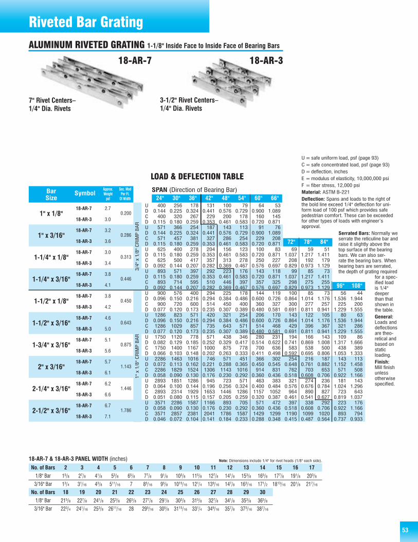
53
400 256 178 131 100 79 64 530.144 0.225 0.324 0.441 0.576 0.729 0.900 1.089400 320 267 229 200 178 160 145
0.115 0.180 0.259 0.353 0.461 0.583 0.720 0.871571 366 254 187 143 113 91 76
0.144 0.225 0.324 0.441 0.576 0.729 0.900 1.089571 457 381 327 286 254 229 208
0.115 0.180 0.259 0.353 0.461 0.583 0.720 0.871625 400 278 204 156 123 100 83 69 59 51
0.115 0.180 0.259 0.353 0.461 0.583 0.720 0.871 1.037 1.217 1.411625 500 417 357 313 278 250 227 208 192 179
0.092 0.144 0.207 0.282 0.369 0.467 0.576 0.697 0.829 0.973 1.129893 571 397 292 223 176 143 118 99 85 73
0.115 0.180 0.259 0.353 0.461 0.583 0.720 0.871 1.037 1.217 1.411893 714 595 510 446 397 357 325 298 275 255
0.092 0.144 0.207 0.282 0.369 0.467 0.576 0.697 0.829 0.973 1.129900 576 400 294 225 178 144 119 100 85 73 56 44
0.096 0.150 0.216 0.294 0.384 0.486 0.600 0.726 0.864 1.014 1.176 1.536 1.944900 720 600 514 450 400 360 327 300 277 257 225 200
0.077 0.120 0.173 0.235 0.307 0.389 0.480 0.581 0.691 0.811 0.941 1.229 1.5551286 823 571 420 321 254 206 170 143 122 105 80 630.096 0.150 0.216 0.294 0.384 0.486 0.600 0.726 0.864 1.014 1.176 1.536 1.9441286 1029 857 735 643 571 514 468 429 396 367 321 2860.077 0.120 0.173 0.235 0.307 0.389 0.480 0.581 0.691 0.811 0.941 1.229 1.5551750 1120 778 571 438 346 280 231 194 166 143 109 860.082 0.129 0.185 0.252 0.329 0.417 0.514 0.622 0.741 0.869 1.008 1.317 1.6661750 1400 1167 1000 875 778 700 636 583 538 500 438 3890.066 0.103 0.148 0.202 0.263 0.333 0.411 0.498 0.592 0.695 0.806 1.053 1.3332286 1463 1016 746 571 451 366 302 254 216 187 143 1130.072 0.113 0.162 0.221 0.288 0.365 0.450 0.545 0.648 0.761 0.882 1.152 1.4582286 1829 1524 1306 1143 1016 914 831 762 703 653 571 5080.058 0.090 0.130 0.176 0.230 0.292 0.360 0.436 0.518 0.608 0.706 0.922 1.1662893 1851 1286 945 723 571 463 383 321 274 236 181 1430.064 0.100 0.144 0.196 0.256 0.324 0.400 0.484 0.576 0.676 0.784 1.024 1.2962893 2314 1929 1653 1446 1286 1157 1052 964 890 827 723 6430.051 0.080 0.115 0.157 0.205 0.259 0.320 0.387 0.461 0.541 0.627 0.819 1.0373571 2286 1587 1166 893 705 571 472 397 338 292 223 1760.058 0.090 0.130 0.176 0.230 0.292 0.360 0.436 0.518 0.608 0.706 0.922 1.1663571 2857 2381 2041 1786 1587 1429 1299 1190 1099 1020 893 7940.046 0.072 0.104 0.141 0.184 0.233 0.288 0.348 0.415 0.487 0.564 0.737 0.933
18-AR-7
18-AR-3
18-AR-7
18-AR-3
18-AR-7
18-AR-3
18-AR-7
18-AR-3
18-AR-7
18-AR-3
18-AR-7
18-AR-3
18-AR-7
18-AR-3
18-AR-7
18-AR-3
18-AR-7
18-AR-3
18-AR-7
18-AR-3
24" 30" 36" 42" 48" 54" 60" 66"
96" 108"
72" 78" 84"
Approx. Sec. ModBar Symbol Weight Per Ft.Size psf Of Width
1" x 1/8"
1" x 3/16"
1-1/4" x 1/8"
1-1/4" x 3/16"
1-1/2" x 1/8"
1-1/2" x 3/16"
1-3/4" x 3/16"
2" x 3/16"
2-1/4" x 3/16"
2-1/2" x 3/16"
0.200
0.286
0.313
0.446
0.450
0.643
0.875
1.143
1.446
1.786
2.7
3.0
3.2
3.6
3.0
3.4
3.8
4.1
3.8
4.2
4.6
5.0
5.1
5.6
5.7
6.1
6.2
6.6
6.7
7.1
SPAN (Direction of Bearing Bar)
LOAD & DEFLECTION TABLE
UDCDUDCDUDCDUDCDUDCDUDCDUDCDUDCDUDCDUDCD
U=safe uniform load, psf (page 93)C= safe concentrated load, psf (page 93)D=deflection, inchesE =modulus of elasticity, 10,000,000 psiF = fiber stress, 12,000 psiMaterial: ASTM B-221Deflection: Spans and loads to the right ofthe bold line exceed 1/4" deflection for uni-form load of 100 psf which provides safepedestrian comfort. These can be exceededfor other types of loads with engineer’sapproval.
Serrated Bars: Normally weserrate the reticuline bar andraise it slightly above thetop surface of the bearingbars. We can also ser-rate the bearing bars. Whenbearing bars are serrated,the depth of grating required
for a spec-ified loadis 1/4"deeperthan thatshown inthe table.General:Loads anddeflectionsare theo-retical andbased onstatic loading.Finish:Mill finishunlessotherwisespecified.
7" Rivet Centers–1/4" Dia. Rivets
3-1/2" Rivet Centers–1/4" Dia. Rivets
18-AR-7 18-AR-3
3/4" x 1/8" CRIMP BAR
1" x 1/8" CRIMP BAR
18-AR-7 & 18-AR-3 PANEL WIDTH (inches) Note: Dimensions include 1/4" for rivet heads (1/8" each side).
No. of Bars 2 3 4 5 6 7 8 9 10 11 12 13 14 15 16 171/8" Bar
3/16" Bar15/8 27/8 41/8 53/8 65/8 77/8 91/8 103/8 115/8 127/8 141/8 153/8 165/8 177/8 191/8 203/8
13/4 31/16 43/8 511/16 7 85/16 95/8 1015/16 121/4 139/16 147/8 163/16 171/2 1813/16 201/8 217/16
1/8" Bar
3/16" Bar215/8 227/8 241/8 253/8 265/8 277/8 291/8 303/8 315/8 327/8 341/8 353/8 365/8
223/4 241/16 253/8 2611/16 28 295/16 305/8 3115/16 331/4 349/16 357/8 373/16 387/16
No. of Bars 18 19 20 21 22 23 24 25 26 27 28 29 30
Riveted Bar GratingALUMINUM RIVETED GRATING 1-1/8" Inside Face to Inside Face of Bearing Bars

54
571 366 254 187 143 113 91 760.144 0.225 0.324 0.441 0.576 0.729 0.900 1.089571 457 381 327 286 254 229 208
0.115 0.180 0.259 0.353 0.461 0.583 0.720 0.871800 512 356 261 200 158 128 106
0.144 0.225 0.324 0.441 0.576 0.729 0.900 1.089800 640 533 457 400 356 320 291
0.115 0.180 0.259 0.353 0.461 0.583 0.720 0.871893 571 397 292 223 176 143 118 99 85 73
0.115 0.180 0.259 0.353 0.461 0.583 0.720 0.871 1.037 1.217 1.411893 714 595 510 446 397 357 325 298 275 255
0.092 0.144 0.207 0.282 0.369 0.467 0.576 0.697 0.829 0.973 1.1291250 800 556 408 313 247 200 165 139 118 1020.115 0.180 0.259 0.353 0.461 0.583 0.720 0.871 1.037 1.217 1.4111250 1000 833 714 625 556 500 455 417 385 3570.092 0.144 0.207 0.282 0.369 0.467 0.576 0.697 0.829 0.973 1.1291286 823 571 420 321 254 206 170 143 122 105 80 630.096 0.150 0.216 0.294 0.384 0.486 0.600 0.726 0.864 1.014 1.176 1.536 1.9441286 1029 857 735 643 571 514 468 429 396 367 321 2860.077 0.120 0.173 0.235 0.307 0.389 0.480 0.581 0.691 0.811 0.941 1.229 1.5551800 1152 800 588 450 356 288 238 200 170 147 113 890.096 0.150 0.216 0.294 0.384 0.486 0.600 0.726 0.864 1.014 1.176 1.536 1.9441800 1440 1200 1029 900 800 720 655 600 554 514 450 4000.077 0.120 0.173 0.235 0.307 0.389 0.480 0.581 0.691 0.811 0.941 1.229 1.5552450 1568 1089 800 613 484 392 324 272 232 200 153 1210.082 0.129 0.185 0.252 0.329 0.417 0.514 0.622 0.741 0.869 1.008 1.317 1.6662450 1960 1633 1400 1225 1089 980 891 817 754 700 613 5440.066 0.103 0.148 0.202 0.263 0.333 0.411 0.498 0.592 0.695 0.806 1.053 1.3333200 2048 1422 1045 800 632 512 423 356 303 261 200 1580.072 0.113 0.162 0.221 0.288 0.365 0.450 0.545 0.648 0.761 0.882 1.152 1.4583200 2560 2133 1829 1600 1422 1280 1164 1067 985 914 800 7110.058 0.090 0.130 0.176 0.230 0.292 0.360 0.436 0.518 0.608 0.706 0.922 1.1664050 2592 1800 1322 1013 800 648 536 450 383 331 253 2000.064 0.100 0.144 0.196 0.256 0.324 0.400 0.484 0.576 0.676 0.784 1.024 1.2964050 3240 2700 2314 2025 1800 1620 1473 1350 1246 1157 1013 9000.051 0.080 0.115 0.157 0.205 0.259 0.320 0.387 0.461 0.541 0.627 0.819 1.0375000 3200 2222 1633 1250 988 800 661 556 473 408 313 2470.058 0.090 0.130 0.176 0.230 0.292 0.360 0.436 0.518 0.608 0.706 0.922 1.1665000 4000 3333 2857 2500 2222 2000 1818 1667 1538 1429 1250 11110.046 0.072 0.104 0.141 0.184 0.233 0.288 0.348 0.415 0.487 0.564 0.737 0.933
12-AR-7
12-AR-3
12-AR-7
12-AR-3
12-AR-7
12-AR-3
12-AR-7
12-AR-3
12-AR-7
12-AR-3
12-AR-7
12-AR-3
12-AR-7
12-AR-3
12-AR-7
12-AR-3
12-AR-7
12-AR-3
12-AR-7
12-AR-3
24" 30" 36" 42" 48" 54" 60" 66"
96" 108"
72" 78" 84"
Approx. Sec. ModBar Symbol Weight Per Ft.Size psf Of Width
1" x 1/8"
1" x 3/16"
1-1/4" x 1/8"
1-1/4" x 3/16"
1-1/2" x 1/8"
1-1/2" x 3/16"
1-3/4" x 3/16"
2" x 3/16"
2-1/4" x 3/16"
2-1/2" x 3/16"
0.286
0.400
0.446
0.625
0.643
0.900
1.225
1.600
2.025
2.500
3.7
4.0
4.4
4.7
4.2
4.5
5.1
5.4
5.2
5.6
6.3
6.6
7.1
7.4
7.8
8.1
8.5
8.8
9.2
9.5
SPAN (Direction of Bearing Bar)
LOAD & DEFLECTION TABLE
UDCDUDCDUDCDUDCDUDCDUDCDUDCDUDCDUDCDUDCD
7" Rivet Centers–1/4" Dia. Rivets
3-1/2" Rivet Centers–1/4" Dia. Rivets
12-AR-7 12-AR-3
Note: Dimensions include 1/4" for rivet heads (1/8" each side).
3/4" x 1/8" CRIMP BAR
1" x 1/8" CRIMP BAR
12-AR-7 & 12-AR-3 PANEL WIDTH (inches)2 3 4 5 6 7 8 9 10 11 12 13 14 15 16 17 18 19 20 21 22 23 24 25
11/4 21/8 3 37/8 43/4 55/8 61/2 73/8 81/4 91/8 10 107/8 113/4 125/8 131/2 143/8 151/4 161/8 17 177/8 183/4 195/8 201/2 213/8
13/8 25/16 31/4 43/16 51/8 61/16 7 715/16 87/8 913/16 103/4 1111/16 125/8 139/16 141/2 157/16 163/8 175/16 181/4 193/16 201/8 211/16 22 2215/1626 27 28 29 30 31 32 33 34 35 36 37 38 39 40 41 42
221/4 231/8 24 247/8 253/4 265/8 271/2 283/8 291/4 301/8 31 317/8 323/4 335/8 341/2 353/8 361/4
237/8 2413/16 253/4 2611/16 275/8 289/16 291/2 307/16 313/8 325/16 331/4 343/16 351/8 361/16 37 3715/16 387/8
No. of Bars1/8" Bar
3/16" Bar
1/8" Bar
3/16" Bar
No. of Bars
U=safe uniform load, psf (page 93)C= safe concentrated load, psf (page 93)D=deflection, inchesE =modulus of elasticity, 10,000,000 psiF = fiber stress, 12,000 psiMaterial: ASTM B-221Deflection: Spans and loads to the right ofthe bold line exceed 1/4" deflection for uni-form load of 100 psf which provides safepedestrian comfort. These can be exceededfor other types of loads with engineer’sapproval.Serrated Bars: Normally we serrate the retic-uline bar and raise it slightly above the topsurface of the bearing bars. We can also ser-
rate the bearing bars. Whenbearing bars are serrated,the depth of grating requiredfor a specified load is 1/4"deeper than that shown inthe table.General: Loads and deflec-tions are theoretical and
based onstatic loading.Finish: Millfinish unlessotherwisespecified.
Riveted Bar GratingALUMINUM RIVETED GRATING 3/4" Inside Face to Inside Face of Bearing Bars
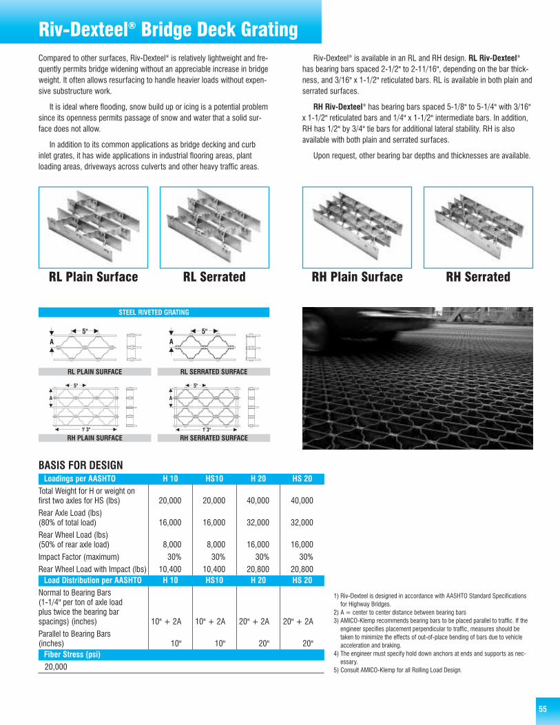
55
Riv-Dexteel® Bridge Deck GratingCompared to other surfaces, Riv-Dexteel® is relatively lightweight and fre-quently permits bridge widening without an appreciable increase in bridgeweight. It often allows resurfacing to handle heavier loads without expen-sive substructure work.
It is ideal where flooding, snow build up or icing is a potential problemsince its openness permits passage of snow and water that a solid sur-face does not allow.
In addition to its common applications as bridge decking and curbinlet grates, it has wide applications in industrial flooring areas, plantloading areas, driveways across culverts and other heavy traffic areas.
Riv-Dexteel® is available in an RL and RH design. RL Riv-Dexteel®
has bearing bars spaced 2-1/2" to 2-11/16", depending on the bar thick-ness, and 3/16" x 1-1/2" reticulated bars. RL is available in both plain andserrated surfaces.
RH Riv-Dexteel® has bearing bars spaced 5-1/8" to 5-1/4" with 3/16"x 1-1/2" reticulated bars and 1/4" x 1-1/2" intermediate bars. In addition,RH has 1/2" by 3/4" tie bars for additional lateral stability. RH is alsoavailable with both plain and serrated surfaces.
Upon request, other bearing bar depths and thicknesses are available.
RL Plain Surface RL Serrated RH SerratedRH Plain Surface
Total Weight for H or weight onfirst two axles for HS (lbs) 20,000 20,000 40,000 40,000
Rear Axle Load (lbs)(80% of total load) 16,000 16,000 32,000 32,000
Rear Wheel Load (lbs)(50% of rear axle load) 8,000 8,000 16,000 16,000
Impact Factor (maximum) 30% 30% 30% 30%
Rear Wheel Load with Impact (lbs) 10,400 10,400 20,800 20,800
BASIS FOR DESIGNLoadings per AASHTO H 10 HS10 H 20 HS 20
Load Distribution per AASHTO H 10 HS10 H 20 HS 20
Fiber Stress (psi)
1) Riv-Dexteel is designed in accordance with AASHTO Standard Specificationsfor Highway Bridges.
2) A = center to center distance between bearing bars3) AMICO-Klemp recommends bearing bars to be placed parallel to traffic. If the
engineer specifies placement perpendicular to traffic, measures should betaken to minimize the effects of out-of-place bending of bars due to vehicleacceleration and braking.
4) The engineer must specify hold down anchors at ends and supports as nec-essary.
5) Consult AMICO-Klemp for all Rolling Load Design.
Normal to Bearing Bars(1-1/4" per ton of axle loadplus twice the bearing barspacings) (inches) 10" + 2A 10" + 2A 20" + 2A 20" + 2A
Parallel to Bearing Bars(inches) 10" 10" 20" 20"
20,000
RL PLAIN SURFACE RL SERRATED SURFACE
RH PLAIN SURFACE RH SERRATED SURFACE
STEEL RIVETED GRATING

56 56
Riv-Dexteel® Bridge Deck Grating
RL-103 2 1/2" x 3/16" 1 1/2" x 3/16" 15.3 0.1953 0.938 2 1/2RL-104 2 1/2" x 1/4" 1 1/2" x 3/16" 17.4 0.2604 1.220 2 9/16RL-105 2 1/2" x 5/16" 1 1/2" x 3/16" 19.5 0.3255 1.488 2 5/8RL-106 2 1/2" x 3/8" 1 1/2" x 3/16" 21.4 0.3906 1.744 2 11/16RL-113 2 3/4" x 3/16" 1 1/2" x 3/16" 16.1 0.2363 1.134 2 1/2RL-114 2 3/4" x 1/4" 1 1/2" x 3/16" 18.4 0.3151 1.476 2 9/16RL-115 2 3/4" x 5/16" 1 1/2" x 3/16" 20.7 0.3939 1.801 2 5/8RL-116 2 3/4" x 3/8" 1 1/2" x 3/16" 22.8 0.4727 2.110 2 11/16RL-123 3" x 3/16" 1 1/2" x 3/16" 16.8 0.2813 1.350 2 1/2RL-124 3" x 1/4" 1 1/2" x 3/16" 19.4 0.3750 1.756 2 9/16RL-125 3" x 5/16" 1 1/2" x 3/16" 21.9 0.4688 2.143 2 5/8RL-126 3" x 3/8" 1 1/2" x 3/16" 24.3 0.5625 2.512 2 11/16RL-134 3 1/4" x 1/4" 1 1/2" x 3/16" 20.4 0.4401 2.061 2 9/16RL-135 3 1/4" x 5/16" 1 1/2" x 3/16" 23.1 0.5501 2.515 2 5/8RL-136 3 1/4" x 3/8" 1 1/2" x 3/16" 25.7 0.6602 2.948 2 11/16RL-144 3 1/2" x 1/4" 2" x 3/16" 23.6 0.5104 2.390 2 9/16RL-145 3 1/2" x 5/16" 2" x 3/16" 26.5 0.6380 2.917 2 5/8RL-146 3 1/2" x 3/8" 2" x 3/16" 29.2 0.7656 3.419 2 11/16RL-154 3 3/4" x 1/4" 2" x 3/16" 24.6 0.5859 2.744 2 9/16RL-155 3 3/4" x 5/16" 2" x 3/16" 27.7 0.7324 3.348 2 5/8RL-156 3 3/4" x 3/8" 2" x 3/16" 30.6 0.8789 3.924 2 11/16RL-164 4" x 1/4" 2" x 3/16" 25.6 0.6667 3.122 2 9/16RL-165 4" x 5/16" 2" x 3/16" 28.9 0.8333 3.810 2 5/8RL-166 4" x 3/8" 2" x 3/16" 32.0 1.0000 4.465 2 11/16RL-184 4 1/2" x 1/4" 2" x 3/16" 27.6 0.8438 3.951 2 9/16RL-185 4 1/2" x 5/16" 2" x 3/16" 31.3 1.0547 4.821 2 5/8RL-186 4 1/2" x 3/8" 2" x 3/16" 34.9 1.2656 5.651 2 11/16RL-204 5" x 1/4" 2" x 3/16" 29.6 1.0417 4.878 2 9/16RL-205 5" x 5/16" 2" x 3/16" 33.7 1.3021 5.952 2 5/8RL-206 5" x 3/8" 2" x 3/16" 37.7 1.5625 6.977 2 11/16
RH-144 3 1/2" x 1/4" 1 1/2" x 3/16" 18.3 0.5104 1.195 5 1/8RH-145 3 1/2" x 5/16" 1 1/2" x 3/16" 19.8 0.6380 1.476 5 3/16RH-146 3 1/2" x 3/8" 1 1/2" x 3/16" 21.3 0.7656 1.750 5 1/4RH-154 3 3/4" x 1/4" 1 1/2" x 3/16" 18.8 0.5859 1.372 5 1/8RH-155 3 3/4" x 5/16" 1 1/2" x 3/16" 20.4 0.7324 1.694 5 3/16RH-156 3 3/4" x 3/8" 1 1/2" x 3/16" 22.0 0.8789 2.009 5 1/4RH-164 4" x 1/4" 1 1/2" x 3/16" 19.3 0.6667 1.561 5 1/8RH-165 4" x 5/16" 1 1/2" x 3/16" 21.0 0.8333 1.928 5 3/16RH-166 4" x 3/8" 1 1/2" x 3/16" 22.7 1.0000 2.286 5 1/4RH-184 4 1/2" x 1/4" 1 1/2" x 3/16" 20.3 0.8438 1.976 5 1/8RH-185 4 1/2" x 5/16" 1 1/2" x 3/16" 22.2 1.0547 2.440 5 3/16RH-186 4 1/2" x 3/8" 1 1/2" x 3/16" 24.2 1.2656 2.893 5 1/4RH-204 5" x 1/4" 1 1/2" x 3/16" 21.3 1.0417 2.439 5 1/8RH-205 5" x 5/16" 1 1/2" x 3/16" 23.5 1.3021 3.012 5 3/16RH-206 5" x 3/8" 1 1/2" x 3/16" 25.6 1.5625 3.571 5 1/4
PANEL WIDTH (inches)Number of Bearing Bars
2 3 4 5 6 7 8 9 10 11 12 13 14 15 16 17 18 19 202-1/2"
2-9/16"
2-5/8"
2-11/16"
5-1/8"
5-3/16"
5-1/4"
3/16"
1/4"
5/16"
3/8"
1/4"
5/16"
3/8"
Type
RL
215/16 57/16 715/16 107/16 1215/16 157/16 1715/16 207/16 2215/16 257/16 2715/16 307/16 3215/16 357/16 3715/16 407/16 4215/16 457/16 4715/16
31/16 55/8 83/16 103/4 135/16 157/8 187/16 21 239/16 261/8 2811/16 311/4 3313/16 363/8 3815/16 411/2 441/16 465/8 493/16
33/16 513/16 87/16 111/16 1311/16 165/16 1815/16 219/16 243/16 2613/16 297/16 321/16 3411/16 375/16 3915/16 429/16 453/16 4713/16 507/16
35/16 6 811/16 113/8 141/16 163/4 197/16 221/8 2413/16 271/2 303/16 327/8 359/16 381/4 4015/16 435/8 465/16 49 5111/16
55/8 103/4 157/8 21 261/8 311/4 363/8 411/2 465/8 513/4 567/8
53/4 1015/16 161/8 215/16 261/2 3111/16 367/8 421/16 471/4 527/16 575/8
57/8 111/8 163/8 215/8 267/8 321/8 373/8 425/8 477/8 531/8 583/8
Note: Dimension includes 1/4" (1/8" each side) for rivet heads.Rivet heads vary with bearing bar thickness.
Type Weight per unit of per ft. of SpacingRL Bearing Bar Size Reticuline Bar Size (psf) grating width grating width (inches)
“A”Section Modulus (in3) Bearing Bar
Bar Spacing“A”
BarThickness
Riv-Dexteel
Type
RH
RH
Note: AMICO-Klemp® recommends bearing bars to be placed parallel to traffic.
Serrated Bars: Normally we serrate the reticuline bar and raise it slightly abovethe top surface of the bearing bars. We can also serrate the bearing bars. Whenbearing bars are serrated, the depth of grating required for a specified load is1/4" deeper than that shown in the table.
Design note: Consult AMICO-Klemp for all Rolling Load Design.
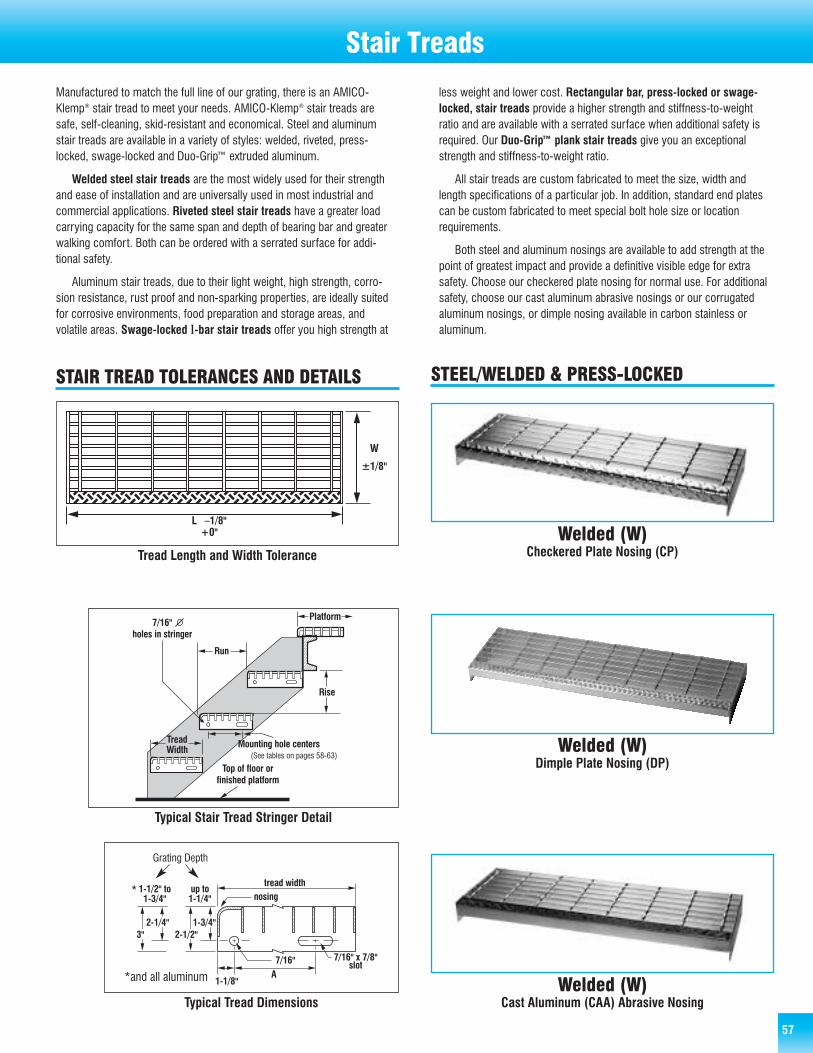
575757
Stair Treads
Tread Length and Width Tolerance
Typical Tread Dimensions
Typical Stair Tread Stringer Detail
Welded (W)Checkered Plate Nosing (CP)
Welded (W)Dimple Plate Nosing (DP)
Welded (W)Cast Aluminum (CAA) Abrasive Nosing
Manufactured to match the full line of our grating, there is an AMICO-Klemp® stair tread to meet your needs. AMICO-Klemp® stair treads aresafe, self-cleaning, skid-resistant and economical. Steel and aluminumstair treads are available in a variety of styles: welded, riveted, press-locked, swage-locked and Duo-Grip™ extruded aluminum.
Welded steel stair treads are the most widely used for their strengthand ease of installation and are universally used in most industrial andcommercial applications. Riveted steel stair treads have a greater loadcarrying capacity for the same span and depth of bearing bar and greaterwalking comfort. Both can be ordered with a serrated surface for addi-tional safety.
Aluminum stair treads, due to their light weight, high strength, corro-sion resistance, rust proof and non-sparking properties, are ideally suitedfor corrosive environments, food preparation and storage areas, andvolatile areas. Swage-locked I-bar stair treads offer you high strength at
less weight and lower cost. Rectangular bar, press-locked or swage-locked, stair treads provide a higher strength and stiffness-to-weightratio and are available with a serrated surface when additional safety isrequired. Our Duo-Grip™ plank stair treads give you an exceptionalstrength and stiffness-to-weight ratio.
All stair treads are custom fabricated to meet the size, width andlength specifications of a particular job. In addition, standard end platescan be custom fabricated to meet special bolt hole size or locationrequirements.
Both steel and aluminum nosings are available to add strength at thepoint of greatest impact and provide a definitive visible edge for extrasafety. Choose our checkered plate nosing for normal use. For additionalsafety, choose our cast aluminum abrasive nosings or our corrugatedaluminum nosings, or dimple nosing available in carbon stainless or aluminum.
STEEL/WELDED & PRESS-LOCKEDSTAIR TREAD TOLERANCES AND DETAILS
*
*and all aluminum
Grating Depth
(See tables on pages 58-63)
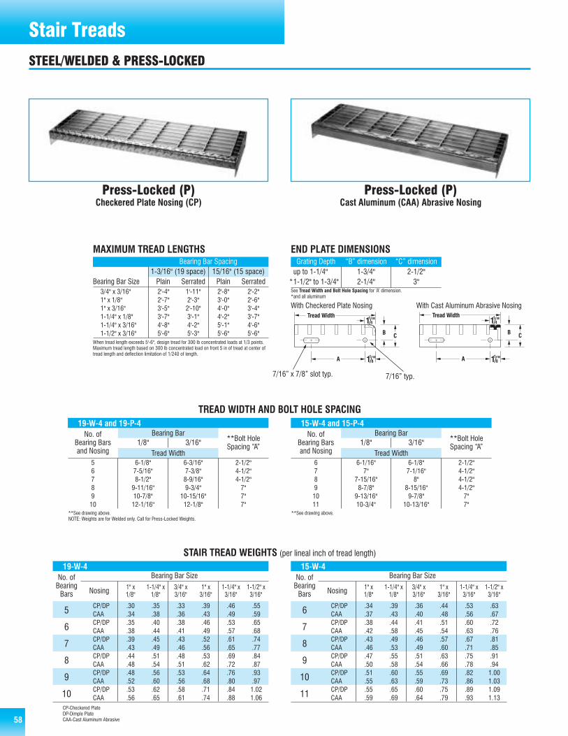
58 5858
Stair Treads
Press-Locked (P)Checkered Plate Nosing (CP)
Press-Locked (P)Cast Aluminum (CAA) Abrasive Nosing
CP/DP .30 .35 .33 .39 .46 .55CAA .34 .38 .36 .43 .49 .59CP/DP .35 .40 .38 .46 .53 .65CAA .38 .44 .41 .49 .57 .68CP/DP .39 .45 .43 .52 .61 .74CAA .43 .49 .46 .56 .65 .77CP/DP .44 .51 .48 .53 .69 .84CAA .48 .54 .51 .62 .72 .87CP/DP .48 .56 .53 .64 .76 .93CAA .52 .60 .56 .68 .80 .97CP/DP .53 .62 .58 .71 .84 1.02CAA .56 .65 .61 .74 .88 1.06
STAIR TREAD WEIGHTS (per lineal inch of tread length)
19-W-4No. ofBearingBars
Bearing Bar Size
Nosing 1" x1/8"
1-1/4" x1/8"
3/4" x3/16"
1" x3/16"
1-1/4" x3/16"
1-1/2" x3/16"
5
6
7
8
9
10
MAXIMUM TREAD LENGTHSBearing Bar Spacing
Bearing Bar Size
CP/DP .34 .39 .36 .44 .53 .63CAA .37 .43 .40 .48 .56 .67CP/DP .38 .44 .41 .51 .60 .72CAA .42 .58 .45 .54 .63 .76CP/DP .43 .49 .46 .57 .67 .81CAA .46 .53 .49 .60 .71 .85CP/DP .47 .55 .51 .63 .75 .91CAA .50 .58 .54 .66 .78 .94CP/DP .51 .60 .55 .69 .82 1.00CAA .55 .63 .59 .73 .86 1.03CP/DP .55 .65 .60 .75 .89 1.09CAA .59 .69 .64 .79 .93 1.13
15-W-4 No. ofBearingBars
Bearing Bar Size
Nosing 1" x1/8"
1-1/4" x1/8"
3/4" x3/16"
1" x3/16"
1-1/4" x3/16"
1-1/2" x3/16"
6
7
8
9
10
11
19-W-4 and 19-P-4No. of
Bearing Barsand Nosing
**Bolt HoleSpacing “A”
Bearing Bar1/8" 3/16"
Tread Width
1-3/16" (19 space) 15/16" (15 space)Plain Serrated Plain Serrated
3/4" x 3/16" 2'-4" 1'-11" 2'-8" 2'-2"1" x 1/8" 2'-7" 2'-3" 3'-0" 2'-6"1" x 3/16" 3'-5" 2'-10" 4'-0" 3'-4"1-1/4" x 1/8" 3'-7" 3'-1" 4'-2" 3'-7"1-1/4" x 3/16" 4'-8" 4'-2" 5'-1" 4'-6"1-1/2" x 3/16" 5'-6" 5'-3" 5'-6" 5'-6"
When tread length exceeds 5'-6", design tread for 300 lb concentrated loads at 1/3 points.Maximum tread length based on 300 lb concentrated load on front 5 in of tread at center oftread length and deflection limitation of 1/240 of length.
TREAD WIDTH AND BOLT HOLE SPACING
5 6-1/8" 6-3/16" 2-1/2"6 7-5/16" 7-3/8" 4-1/2"7 8-1/2" 8-9/16" 4-1/2"8 9-11/16" 9-3/4" 7"9 10-7/8" 10-15/16" 7"10 12-1/16" 12-1/8" 7"
END PLATE DIMENSIONSGrating Depth “B” dimension “C” dimensionup to 1-1/4" 1-3/4" 2-1/2"1-1/2" to 1-3/4" 2-1/4" 3"
See Tread Width and Bolt Hole Spacing for ‘A’ dimension. *and all aluminum
CP-Checkered PlateDP-Dimple PlateCAA-Cast Aluminum Abrasive
15-W-4 and 15-P-4No. of
Bearing Barsand Nosing
**Bolt HoleSpacing “A”
Bearing Bar1/8" 3/16"
Tread Width6 6-1/16" 6-1/8" 2-1/2"7 7" 7-1/16" 4-1/2"8 7-15/16" 8" 4-1/2"9 8-7/8" 8-15/16" 4-1/2"10 9-13/16" 9-7/8" 7"11 10-3/4" 10-13/16" 7"
With Checkered Plate Nosing With Cast Aluminum Abrasive Nosing
STEEL/WELDED & PRESS-LOCKED
*
**See drawing above.**See drawing above.NOTE: Weights are for Welded only. Call for Press-Locked Weights.
7/16” typ.7/16” x 7/8” slot typ.

595959
Stair Treads
Riveted (R)Checker Plate Nosing (CP)
Riveted (R)Cast Aluminum (CAA) Abrasive Nosing
CP .38 .41 .42 .48 .54 .59CAA .43 .43 .49 .53 .58 .64CP .45 .49 .49 .57 .64 .71CAA .50 .54 .57 .62 .69 .76CP .53 .57 .57 .66 .75 .84CAA .58 .62 .65 .71 .80 89CP .60 .65 .65 .75 .85 .96CAA .65 .70 .74 .80 .90 1.01CP .67 .72 .73 .85 .96 1.08CAA .72 .77 .83 .90 1.01 1.13CP .74 .80 .81 .94 1.07 1.20CAA .79 .85 .90 .99 1.12 1.25
STAIR TREAD WEIGHTS (per lineal inch of tread length)
18-R-7No. ofBearingBars
Bearing Bar Size
Nosing 1" x1/8"
1-1/4" x1/8"
3/4" x3/16"
1" x3/16"
1-1/4" x3/16"
1-1/2" x3/16"
5
6
7
8
9
10
CP .45 .49 .47 .55 .61 .68CAA .50 .54 .52 .60 .66 .73CP .52 .57 .59 .63 .71 .80CAA .56 .62 .59 .68 .76 .84CP .58 .64 .62 .72 .81 .91CAA .63 .69 .67 .77 .86 .96CP .65 .72 .69 .81 .91 1.02CAA .70 .77 .74 .86 .96 1.03CP .72 .80 .77 .90 1.01 1.14CAA .77 .85 .81 .94 1.04 1.19CP .79 .88 .84 .98 1.11 1.25CAA .84 .92 .89 1.03 1.16 1.30
12-R-7No. ofBearingBars
Bearing Bar Size
Nosing 1" x1/8"
1-1/4" x1/8"
3/4" x3/16"
1" x3/16"
1-1/4" x3/16"
1-1/2" x3/16"
6
7
8
9
10
11
18-R-7No. of
Bearing Barsand Nosing
**Bolt HoleSpacing “A”
Bearing Bar1/8" 3/16"
Tread Width
TREAD WIDTH AND BOLT HOLE SPACING
5 6-3/8" 6-11/16" 2-1/2"6 7-5/8" 8" 4-1/2"7 8-7/8" 9-5/16" 4-1/2"8 10-1/8" 10-5/8" 7"9 11-3/8" 11-15/16" 7"10 12-5/8" 13-1/4" 7"
END PLATE DIMENSIONSGrating Depth “B” dimension “C” dimensionup to 1-1/4" 1-3/4" 2-1/2"1-1/2" to 1-3/4" 2-1/4" 3"
See Tread Width and Bolt Hole Spacing for ‘A’ dimension.*and all aluminum
12-R-7No. of
Bearing Barsand Nosing
**Bolt HoleSpacing “A”
Bearing Bar1/8" 3/16"
Tread Width6 5-3/4" 6-1/8" 2-1/2"7 6-5/8" 7-1/16" 4-1/2"8 7-1/2" 8" 4-1/2"9 8-3/8" 8-15/16" 4-1/2"10 9-1/4" 9-7/8" 7"11 10-1/8" 10-13/16" 7"
With Checker Plate Nosing With Cast Aluminum Abrasive Nosing
MAXIMUM TREAD LENGTHSBearing Bar Spacing
Bearing Bar Size1-1/4" (18 space) 3/4" (12 space)Plain Serrated Plain Serrated
3/4" x 3/16" 2'-0" 1'-5" 2'-8" 1'-9"1" x 1/8" 2'-7" 1'-11" 3'-0" 2'-1"1" x 3/16" 2'-10" 2'-0" 4'-0" 2'-8"1-1/4" x 1/8" 3'-7" 2'-7" 4'-2" 3'-0"1-1/4" x 3/16" 3'-10" 2'-10" 5'-1" 4'-0"1-1/2" x 3/16" 5'-2" 3'-10" 5'-6" 5'-1"
When tread length exceeds 5'-6", design tread for 300 lb concentrated loads at 1/3 points.Maximum tread length based on 300 lb concentrated load on front 5 in of tread at center oftread length and deflection limitation of 1/240 of length. Maximum lengths for serrated applyonly if bearing bars are serrated.
STEEL/RIVETED
*
**See drawing above.**See drawing above.
7/16” typ.7/16” x 7/8” slot typ.

60 6060
Stair Treads
Swage-Locked (SR)Corrugated Aluminum Nosing (CORR)
Swage-Locked (SR)Cast Aluminum Abrasive Nosing (CAA)
Press-Locked (AP)Corrugated Aluminum Nosing (CORR)
Press-Locked (AP)Cast Aluminum Abrasive Nosing (CAA)
CORR .15 .17 .20 .22CAA .19 .21 .24 .26CORR .17 .20 .23 .26CAA .21 .23 .27 .30CORR .19 .23 .27 .30CAA .23 .26 .31 .33CORR .22 .25 .30 .34CAA .26 .29 .34 .38CORR .24 .28 .33 .38CAA .28 .32 .37 .41CORR .26 .31 .37 .41CAA .30 .35 .41 .46
STAIR TREAD WEIGHTS (per lineal inch of tread length)
19-SR-4No. ofBearingBars
Bearing Bar Size
Nosing 1" x3/16"
1-1/4" x3/16"
1-1/2" x3/16"
1-3/4" x3/16"
5
6
7
8
9
10
CORR .16 .19 .23 .25CAA .21 .23 .27 .29CORR .19 .22 .26 .29CAA .23 .26 .30 .33CORR .21 .24 .29 .33CAA .25 .29 .33 .36CORR .23 .27 .32 .36CAA .27 .31 .36 .41CORR .25 .30 .35 .40CAA .29 .34 .39 .44CORR .28 .33 .39 .44CAA .32 .37 .43 .48
15-SR-4No. ofBearingBars
Bearing Bar Size
Nosing 1" x3/16"
1-1/4" x3/16"
1-1/2" x3/16"
1-3/4" x3/16"
6
7
8
9
10
11
MAXIMUM TREAD LENGTHSBearing Bar Spacing
Bearing Bar Size
19-SR-4 and 19-AP-4No. of
Bearing Barsand Nosing
**Bolt HoleSpacing “A”
Bearing Bar3/16"
Tread Width
1-3/16" (19 space) 15/16" (15 space)Plain Serrated Plain Serrated
1" x 3/16" 2'-4" 2'-2" 2'-6" 2'-3"1-1/4" x 3/16" 2'-10" 2'-7" 3'-1" 2'-9"1-1/2" x 3/16" 3'-6" 3'-2" 3'-10" 3'-5"1-3/4" x 3/16" 4'-3" 3'-10" 4'-8" 4'-3"
When tread length exceeds 5'-6", design tread for 300 lb concentrated loads at 1/3 points.Maximum tread length based on 300 lb concentrated load on front 5 in of tread at center oftread length and deflection limitation of 1/240 of length.
TREAD WIDTH & BOLT HOLE SPACING
5 6-3/16" 2-1/2"6 7-3/8" 4-1/2"7 8-9/16" 4-1/2"8 9-3/4" 7"9 10-15/16" 7"10 12-1/8" 7"
END PLATE DIMENSIONSGrating Depth “B” dimension “C” dimensionup to 1-1/4" 1-3/4" 2-1/2"1-1/2" to 1-3/4" 2-1/4" 3"
See Tread Width and Bolt Hole Spacing for ‘A’ dimension.*and all aluminum
15-SR-4 and 15-AP-4No. of
Bearing Barsand Nosing
**Bolt HoleSpacing “A”
Bearing Bar3/16"
Tread Width6 6-1/8" 2-1/2"7 7-1/16" 4-1/2"8 8" 4-1/2"9 8-15/16" 4-1/2"10 9-7/8" 7"11 10-13/16" 7"
With Corrugated Aluminum Nosing
With Cast Aluminum Abrasive Nosing
ALUMINUM/RECTANGULAR BAR SWAGE-LOCKED & PRESS-LOCKED
*
**See drawing above.**See drawing above.
NOTE: Weights are for Swage-Locked only. Call for Weights onPressed-Locked.
7/16” typ.7/16” x 7/8” slot typ.

6161
MAXIMUM TREAD LENGTHSBearing Bar Spacing
Bearing Bar Size 1-3/16" (19 space) 15/16" (15 space)1" x 1/4" 2'-4" 2'-6"1-1/4" x 1/4" 2'-10" 3'-1"1-1/2" x 1/4" 3'-6" 3'-10"1-3/4" x 1/4" 4'-3" 4'-8"
When tread length exceeds 5'-6", design tread for 300 lb concentrated loads at 1/3 points.Maximum tread length based on 300 lb concentrated load on front 5 in of tread at center oftread length and deflection limitation of 1/240 of length.
Stair Treads
Swage-Locked (SII)Corrugated Aluminum Nosing (CORR)
Swage-Locked (SII)Cast Aluminum Abrasive Nosing (CAA)
CORR .13 .14 .16 .18CAA .17 .18 .20 .22CORR .14 .16 .19 .21CAA .18 .21 .23 .25CORR .16 .19 .21 .24CAA .20 .23 .25 .28CORR .18 .21 .24 .26CAA .22 .25 .28 .31CORR .20 .23 .26 .29CAA .24 .27 .31 .34CORR .22 .25 .29 .33CAA .26 .29 .33 .36
STAIR TREAD WEIGHTS (per lineal inch of tread length)
19-SII-4No. ofBearingBars
Bearing Bar Size
Nosing 1" x1/4"
1-1/4" x1/4"
1-1/2" x1/4"
1-3/4" x1/4"
5
6
7
8
9
10
CORR .14 .16 .18 .20CAA .18 .20 .22 .24CORR .16 .18 .20 .23CAA .20 .22 .24 .27CORR .17 .20 .22 .26CAA .21 .24 .27 .29CORR .19 .22 .25 .28CAA .23 .26 .29 .33CORR .21 .24 .28 .31CAA .25 .28 .30 .35CORR .23 .26 .30 .33CAA .27 .31 .34 .38
15-SII-4No. ofBearingBars
Bearing Bar Size
Nosing 1" x1/4"
1-1/4" x1/4"
1-1/2" x1/4"
1-3/4" x1/4"
6
7
8
9
10
11
19-SII-4No. of
Bearing Barsand Nosing
**Bolt HoleSpacing “A”
Bearing Bar1/4"
Tread Width
TREAD WIDTH & BOLT HOLE SPACING
5 6-1/4" 2-1/2"6 7-7/16" 4-1/2"7 8-5/8" 4-1/2"8 9-13/16" 7"9 11" 7"10 12-3/16" 7"
END PLATE DIMENSIONSGrating Depth “B” dimension “C” dimensionup to 1-1/4" 1-3/4" 2-1/2"1-1/2" to 1-3/4" 2-1/4" 3"
See Tread Width and Bolt Hole Spacing for ‘A’ dimension.*and all aluminum
15-SII-4No. of
Bearing Barsand Nosing
**Bolt HoleSpacing “A”
Bearing Bar1/4"
Tread Width6 6-3/16" 2-1/2"7 7-1/8" 4-1/2"8 8-1/16" 4-1/2"9 9" 4-1/2"10 9-15/16" 7"11 10-7/8" 7"
With Corrugated Aluminum Nosing With Cast Aluminum Abrasive Nosing
ALUMINUM/II-BAR SWAGE-LOCK
*
**See drawing above.**See drawing above.
7/16” typ.7/16” x 7/8” slot typ.
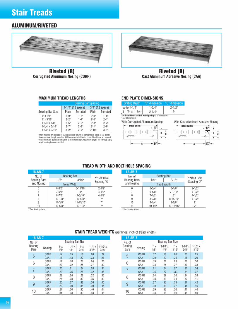
62 62
Stair Treads
Riveted (R)Corrugated Aluminum Nosing (CORR)
Riveted (R)Cast Aluminum Abrasive Nosing (CAA)
CORR .14 .15 .18 .20 .22CAA .18 .18 .22 .23 .26CORR .17 .18 .21 .24 .26CAA .20 .22 .25 .27 .30CORR .20 .21 .24 .28 .31CAA .23 .25 .28 .32 .35CORR .22 .24 .28 .32 .36CAA .26 .28 .32 .35 .39CORR .25 .27 .32 .36 .40CAA .29 .30 .35 .39 .44CORR .27 .30 .35 .40 .44CAA .31 .33 .39 .43 .48
STAIR TREAD WEIGHTS (per lineal inch of tread length)
18-AR-7No. ofBearingBars
Bearing Bar Size
Nosing
5
6
7
8
9
10
MAXIMUM TREAD LENGTHSBearing Bar Spacing
Bearing Bar Size
CORR .17 .18 .20 .23 .25CAA .20 .22 .24 .26 .29CORR .19 .21 .23 .26 .30CAA .23 .25 .27 .30 .33CORR .21 .24 .27 .30 .34CAA .25 .27 ..30 .34 .37CORR .24 .27 .30 .34 .38CAA .28 .30 .34 .37 .41CORR .27 .30 .33 .37 .42CAA .30 .33 .27 .41 .46CORR .29 .33 .36 .41 .46CAA .33 .36 .40 .45 .50
12-AR-7No. ofBearingBars
Bearing Bar Size
Nosing 1" x1/8"
1-1/4" x1/8"
1" x3/16"
1-1/4" x3/16"
1-1/2" x3/16"
5
6
7
8
9
10
18-AR-7No. of
Bearing Barsand Nosing
**Bolt HoleSpacing “A”
Bearing Bar1/8" 3/16"
Tread Width
1-1/4" (18 space) 3/4" (12 space)Plain Serrated Plain Serrated
1" x 1/8" 2'-0" 1'-6" 2'-3" 1'-8"1" x 3/16" 2'-2" 1'-7" 2'-6" 2'-1"1-1/4" x 1/8" 2'-6" 2'-0" 2'-8" 2'-3"1-1/4" x 3/16" 2'-7" 2'-2" 3'-1" 2'-6"1-1/2" x 3/16" 3'-2" 2'-7" 3'-10" 3'-1"
When tread length exceeds 5'-6", design tread for 300 lb concentrated loads at 1/3 points.Maximum tread length based on 300 lb concentrated load on front 5 in of tread at center oftread length and deflection limitation of 1/240 of length. Maximum lengths for serrated applyonly if bearing bars are serrated.
TREAD WIDTH AND BOLT HOLE SPACING
5 6-3/8" 6-11/16" 2-1/2"6 7-5/8" 8" 4-1/2"7 8-7/8" 9-5/16" 4-1/2"8 10-1/8" 10-5/8" 7"9 11-3/8" 11-15/16" 7"10 12-5/8" 13-1/4" 7"
END PLATE DIMENSIONSGrating Depth “B” dimension “C” dimensionup to 1-1/4" 1-3/4" 2-1/2"1-1/2" to 1-3/4" 2-1/4" 3"
See Tread Width and Bolt Hole Spacing for ‘A’ dimension.*and all aluminum
12-AR-7No. of
Bearing Barsand Nosing
**Bolt HoleSpacing “A”
Bearing Bar1/8" 3/16"
Tread Width6 5-3/4" 6-1/8" 2-1/2"7 6-5/8" 7-1/16" 4-1/2"8 7-1/2" 8" 4-1/2"9 8-3/8" 8-15/16" 4-1/2"10 9-1/4" 9-7/8" 7"11 10-1/8" 10-13/16" 7"
With Corrugated Aluminum Nosing With Cast Aluminum Abrasive Nosing
ALUMINUM/RIVETED
*
**See drawing above.**See drawing above.
1" x1/8"
1-1/4" x1/8"
1" x3/16"
1-1/4" x3/16"
1-1/2" x3/16"

636363
Stair Treads
Duo-Grip™ (DG) Punched Duo-Grip™ (DG) Unpunched
PHYSICAL PROPERTIES
LOAD TABLE (plf)TreadWidth
Span (ft)12" 18" 24" 30" 36" 42" 48" 54"
2633 1170 658 421 293 215 165 130
3346 1487 837 535 372 273 209 165
3558 1581 890 569 395 290 222 176
4419 1964 1105 707 491 361 276 218
DG-3175 3" x 1-3/4" 1.195 plf .3949 .4323
DG-4175 4" x 1-3/4" 1.696 plf .5019 .5579
DG-6175 6" x 1-3/4" 2.041 plf .5337 .6532
DG-9175 9" x 1-3/4" 2.892 plf .6629 .8445
3/4" 1-1/4" .10 pli3/4" 2-1/4" .15 pli1-1/2" 3" .18 pli1-1/2" 6" .26 pli
TREAD APPLICATIONSTread Widths Maximum Tread Length A B Wt. Unpunched3" x 1-3/4" 4'-3"4" x 1-3/4" 5'-0"6" x 1-3/4" 5'-5"9" x 1-3/4" 5'-6"
Maximum tread length based on 300 lb concentrated load on entire tread at center of tread length and deflection limitationof 1/240 of length.
END PLATE DIMENSIONS
3"
4"
6"
9"
Section VIew Symbol SizeWeight(extrusiononly)
Section PropertiesSection
Modulus (in3)Moment ofInertia (in4)
ALUMINUM/DUO-GRIP™
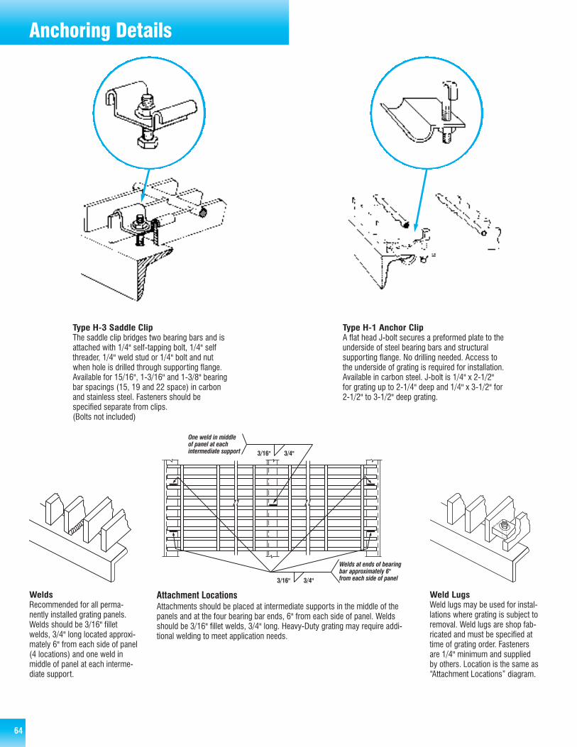
64 6464
Anchoring Details
Type H-3 Saddle ClipThe saddle clip bridges two bearing bars and isattached with 1/4" self-tapping bolt, 1/4" selfthreader, 1/4" weld stud or 1/4" bolt and nutwhen hole is drilled through supporting flange.Available for 15/16", 1-3/16" and 1-3/8" bearingbar spacings (15, 19 and 22 space) in carbonand stainless steel. Fasteners should be specified separate from clips.(Bolts not included)
Type H-1 Anchor ClipA flat head J-bolt secures a preformed plate to theunderside of steel bearing bars and structuralsupporting flange. No drilling needed. Access tothe underside of grating is required for installation.Available in carbon steel. J-bolt is 1/4" x 2-1/2"for grating up to 2-1/4" deep and 1/4" x 3-1/2" for2-1/2" to 3-1/2" deep grating.
WeldsRecommended for all perma-nently installed grating panels.Welds should be 3/16" filletwelds, 3/4" long located approxi-mately 6" from each side of panel(4 locations) and one weld inmiddle of panel at each interme-diate support.
Weld LugsWeld lugs may be used for instal-lations where grating is subject toremoval. Weld lugs are shop fab-ricated and must be specified attime of grating order. Fastenersare 1/4" minimum and suppliedby others. Location is the same as“Attachment Locations” diagram.
Attachment LocationsAttachments should be placed at intermediate supports in the middle of thepanels and at the four bearing bar ends, 6" from each side of panel. Weldsshould be 3/16" fillet welds, 3/4" long. Heavy-Duty grating may require addi-tional welding to meet application needs.

6565
Installation Clearances
*Cross rods may extend 1/8" from bearing bars.
All rectangular cutouts are made to the next bearingbar beyond the penetration with a clearance not toexceed bearing bar spacing.
All panel width dimensions(including cutout) are givento the nearest bearing bar.
I-Beam and Angle Curb I-Beam and Kickplate I-Beam and Handrail I-Beam
Channel Toed Out Channel Toed In Angle in Concrete Concrete
*1/4" is recommended but dimension may vary due to bearing bar spacing.Dimension should not exceed bearing bar spacing.
PANEL TO PANEL CLEARANCES AND CUTOUT CLEARANCES
SUPPORT CLEARANCES
1” Minimum Bearing Surface
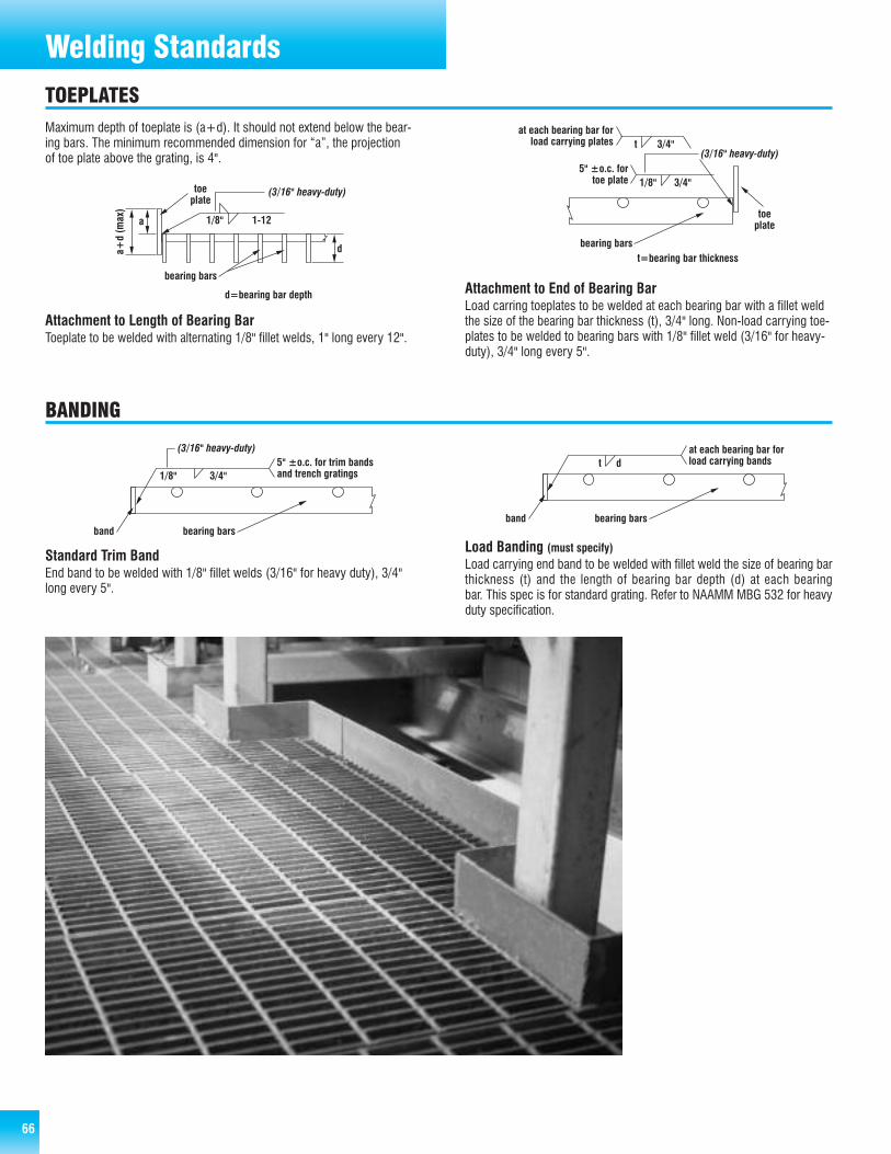
66 66
Welding Standards
Attachment to Length of Bearing BarToeplate to be welded with alternating 1/8" fillet welds, 1" long every 12".
Standard Trim BandEnd band to be welded with 1/8" fillet welds (3/16" for heavy duty), 3/4"long every 5".
Load Banding (must specify)Load carrying end band to be welded with fillet weld the size of bearing barthickness (t) and the length of bearing bar depth (d) at each bearing bar. This spec is for standard grating. Refer to NAAMM MBG 532 for heavyduty specification.
Attachment to End of Bearing BarLoad carring toeplates to be welded at each bearing bar with a fillet weldthe size of the bearing bar thickness (t), 3/4" long. Non-load carrying toe-plates to be welded to bearing bars with 1/8" fillet weld (3/16" for heavy-duty), 3/4" long every 5".
Maximum depth of toeplate is (a+d). It should not extend below the bear-ing bars. The minimum recommended dimension for “a”, the projectionof toe plate above the grating, is 4".
TOEPLATES
BANDING

676767
Manufacturing Tolerances
Cross Rod Spacing and AlignmentCross rods should not vary more than 1/8 in 12 in either direction fromperpendicular alignment with bearing bars. The tolerance of the cross barspacing for 5' in length is ±1/4". Bearing Bar Lean
Bearing bar lean must not exceed a slope of 1-1/4 to 12.
Cross Bar LeanCross bar lean must not exceed a slope of 2-1/2 to 12.
Cross Rod PositionThe top of the cross rod should not project more than 1/16" above the topof the bearing bars for standard grating (1/8" for heavy-duty) and shouldnot extend more than 1/8" from side of bearing bars.
Overall Dimensions and SquarenessD= Overall diagonal dimensionW= Length of cross rods including extensions outside of bearing barsL= Length of bearing bars
Longitudinal BowLongitudinal bow should be less than 1/200 of the length for standard grating (1/240 for heavy duty).
Tranverse BowBefore banding, the tranverse bow should be less than 1/8" per foot ofwidth.
PANEL TOLERANCES
BEARING BAR AND CROSS ROD TOLERANCES

68 6868
Glossary
Anchor ❚❚ A device by which grating is attached to its supports.
Band ❚❚ A flat bar welded to a side or end of a grating panel, or along theline of a cutout, and extending neither above or below the bearing bars.
Load-carrying Band—A band used in a cutout to transfer the loadfrom unsupported bearing bars in the cutout to the supported bearingbars.
Trim Band—A band which carries no load, but is used chiefly toimprove appearance and to protect open ends of bearing bars.
Bearing Bars ❚❚ Load-carrying bars extending in the direction of the grat-ing span.
Bearing Bar Centers (spacing) ❚❚ The distance center to center of thebearing bars.
Carriers (Punched Plate) ❚❚ Flats or angles which are welded to the grat-ing panel and nosing of a stair tread and are attached to a stair stringer tosupport the tread.
Clear Opening ❚❚ The distance between faces of bearing bars in a rectan-gular grating, or between a bent connecting bar and a bearing bar in a riv-eted grating.
Cross Rods or Cross Bars ❚❚ The connecting rods or bars which extendperpendicular across bearing bars. Where they intersect the bearing bars,they are welded, forged or mechanically locked to them.
Cross Rod or Cross Bar Centers (spacing) ❚❚ The distance center to cen-ter of the cross rods or bars.
Curved Cut ❚❚ A cutout following a curved pattern.
Cutout ❚❚ An area of grating removed to clear an obstruction or to permitpipes, ducts, columns, etc. to pass through the grating.
End Gauge ❚❚ The distance from the centerline of the last cross rod to theend of the panel.
Finish ❚❚ The coating, usually paint or galvanizing, which is applied to thegrating.
Grating ❚❚ An open grid assembly of metal bars in which the bearing bars,running in one direction, are spaced by rigid cross bars attached to them.
I-Bar ❚❚ An extruded aluminum bearing bar having a cross sectional shaperesembling the letter “I”.
Length ❚❚ The dimension of a grating panel measured parallel to the bear-ing bars.
Nosing ❚❚ A special L-section member serving as the front or leading edgeof a stair tread, or of grating at the head of a stair. Usually manufacturedof checkered plate, cast iron or aluminum abrasive material.
Plain Bars ❚❚ Non-serrated
Press-Locked ❚❚ A method for manufacturing grating where the bearingbars are locked in position by a specialized press fit with cross bar defor-mation instead of riveting or welding.
Radially Cut Grating ❚❚ Rectangular grating which is cut into panelsshaped as annular segments, for use in circular or annular areas.
Reticuline Bar ❚❚ A sinuously bent connecting bar extending between twoadjacent bearing bars, alternately contacting and being riveted to each.
Reversible Grating ❚❚ Grating so constructed that it may be installedeither side up, with no difference in appearance or carrying capacity.
Rivet Centers ❚❚ The distance center to center of rivets along one bearingbar.
Riveted Grating ❚❚ Grating composed of straight bearing bars and bentconnecting bars which are joined at their contact points by riveting.
Serrated Grating ❚❚ Grating which has the top surfaces of the bearingbars notched for slip resistance.
Span of Grating ❚❚ The distance between points of grating support, or thedirection of this dimension. It must always be measured parallel to thebearing bars.
Straight Cut ❚❚ That portion of the cut edge or cutout of grating which fol-lows a straight line.
Swage-Locked ❚❚ Grating manufactured by altering the cross sectionalshape of a metal cross bar by applying pressure through dies.
Toeplate ❚❚ A flat bar attached flat against the outer edge of a grating panelor rear edge of tread, and projecting above the top surface of grating ortread to form a lip or curb.
Tread ❚❚ A panel of grating having carrier end plates and nosing attachedby welding, and designed specifically to serve as a stair tread.
Welded Grating ❚❚ Grating in which the bearing bars and cross bars arejoined at their intersections by resistance welding or conventional handwelding. A resistance weld is obtained by the heat produced by the resis-tance of the material to the flow of electric current causing the material tobecome plastic. At this point, the pressure on the cross bar is rapidlyincreased causing the cross bar to penetrate the bearing bar so that theyare fused together.
Width ❚❚ The overall dimension of a grating panel, measured perpendicularto the bearing bars.

696969
Grating Design Data
b = thickness of rectangular bearing bar, inchesd = depth of bearing bar, inchesAw = center to center distance between bearing bars in welded and
press-locked gratings, inchesC = concentrated load at midspan = 4FSw/L pounds per foot of width
(pfw)Dc = deflection under concentrated load = CL3/48 EIw inchesDu = deflection under uniform load = 5UL4/12(384)EIw inchesE = modulus of elasticity, pounds per square inch (psi)
Steel: E = 29,000,000 psi = 29 (10)6Stainless Steel: E = 28,000,000 psi = 28 (10)6Aluminum: E = 10,000,000 psi = (10)7
F = allowable fiber unit stress, psiASTM A-1011: F = 18,000 psi (Steel, Carbon Hot Rolled Sheet and
Strip, Commercial Quality AISI 1020)ASTM A-36: F = 20,000 psi (Structural Steel (Bars only))ASTM A167: F = 20,000 psi (Type 304 and 316, Stainless Steel)
F = 16,500 psi (Type 304L and 316L, StainlessSteel)
ASTM B-221: F = 12,000 psi (6061-T6 Alloy)F = 10,000 psi (6063-T6 Alloy)
Ib = moment of inertia of a rectangular bar = bd3/12 in4
Iw = moment of inertia of grating per foot of width = KI in4
K = number of bearing bars per foot of grating width = 12/AwL = span of grating between reaction points, inchesMb = maximum bending moment of bearing bar, in-lbsMw = maximum bending moment of grating per foot of width, in-lbsMu = maximum bending moment under uniform load = FSw = UL2/96
in-lbsMc = maximum bending moment under concentrated load = FSw =
CL/4 in-lbsSb = section modulus of a rectangular bar = bd2/6 in.3
Sw = section modulus per foot of grating width = KSb in.3
U = uniform load = 96fSw/L2 psf = 96M/L2 pounds per square foot (psf)
Type of Grating = 19-W-4-63 welded carbon steel gratingSize of Bar = 1-1/2 x 3/16Span = 54 inchesAw = bearing bar spacing = 1.1875 inchesK = number of bearing bars in panel width = 12/Aw = 12/1.1875 =
10.105F = allowable fiber stress = 18,000 psiE = 29,000,000 psiSw = section modulus of grating per foot of width = Kbd2/6 = 10.105 x
0.1875 (1.5)2/6 = 0.711 in.3
Iw = moment of inertia of grating per foot of width = Kbd3/12 = 10.105x 0.1875 (1.5)3/12 = 0.533 in.3
Mw = maximum bending moment for grating per foot of width = FSw =18,000 x 0.711 = 12,800 in.-lbs.
Allowable Concentrated Load and Deflection for 19-W-4-63:C = allowable load = 4Mw/L = 4 x 12,800/54 = 948 pfwDc = deflection = CL3/48EIw = 948 x 543/(48 x 29 x 106 x 0.533) =
0.201 inches
Allowable Uniform Load and Deflection for 19-W-4-63:U = allowable load = 96Mw/L2 = 96 x 12,800/542 = 421 psfDu = deflection = 5UL4/4608EIw = 5 x 421 x 544/(4608 x 29 x 106 x
0.533) = 0.251 inches
SAMPLE CALCULATION: STEEL
DESIGN NOMENCLATURE

70 7070
For a span of 5'-0", the minimum size bearing bar to sustain 225 psf loadis:
Type of Grating = 19-SI-4-64 aluminum swage-locked gratingSize of I-Bar = 1-1/2 x 1/4Equivalent Rectangular Bar for calculation purposes = 1-1/2 x 3/16 (see
note 3)Span = 60 inchesAw = bearing bar spacing = 1.1875 inchesK= number of bearing bars in panel width = 12/Aw = 12/1.1875 =
10.105F= allowable fiber stress = 12,000 psiE= 10,000,000 psiSw = section modulus of grating per foot of width = Kbd2/6 = 10.105 x
0.1875 (1.5)2/6 = 0.711 in3
Iw = moment of inertia of grating per foot of width = Kbd3/12 = 10.105x 0.1875 (1.5)3/12 = 0.533 in3
Mw = maximum bending moment for grating per foot of width = FSw =12,000 x 0.711 = 8,532 in-lbs
Allowable Uniform Load and Deflection for 19-SI-4-64:U = allowable load = 96Mw/L2 = 96 x Mw/602 = 96 x 12,000 x
0.711/602 = 227.5 psfDu = deflection = 5UL4/4608EIg = 5 x 227.5 x 604/(4608 x 10 x 106 x
0.533) = 0.6 inchesDeflection is directly proportional to load (actual load/allowable load):Dactual = Du x Uactual/Uallowable = 0.6 x 225/227.5 = 0.5934 inchesDactual = 0.5934 inches > recommended limitation of deflection =
L/240=.25 inches
Try a grating with a larger moment of inertia to reduce deflection:19-SI-4-64 (1-1/2 x 3/16 equivalent rectangular bar):If Du = .25 inches, then Iw required = 5UL4/4608EDu = 5 x 225 x
604/(4608 x 10 x 106 x .25) = 1.2656 in4
Using a larger size: 19-SI-4-94 (Rectangular bar equivalent = 2-1/4 x3/16)
Iw = K x Ib = 10.105 x 0.1780 = 1.799 in4
Allowable Uniform Load and Deflection for 19-SI-4-94:U = allowable load = 512 lbsD = deflection = 5UL4/4608EIg = 5 x 512 x 604/(4608 x 10 x 106 x
1.799) = 0.40 inchesDeflection is directly proportional to load (actual load/allowable load):Du = Du x Uactual/Uallowable = 0.40 (225)/512 = 0.176 inches OK
deflection < L/240 (.25 inches)
1" x 1/4" 1" x 3/16" .120 .144 .0156 .03131-1/4" x 1/4" 1-1/4" x 3/16" .150 .180 .0305 .04881-1/2" x 1/4" 1-1/2" x 3/16" .180 .216 .0507 .07031-3/4" x 1/4" 1-3/4" x 3/16" .210 .252 .0837 .09572" x 1/4" 2" x 3/16" .240 .288 .1250 .12502-1/4" x 1/4" 2-1/4" x 3/16" .270 .324 .1780 .15822-1/2" x 1/2" 2-1/2" x 3/16" .300 .360 .2441 .1953
This table is to be used by engineers to select aluminum I-bar sizes throughhand calculations. In most cases, the Load and Span tables in the front ofthis catalog can be used for product selection.
Notes:1) For additional information, see NAAMM’s MBG-534, Engineering
Design Manual2) Uniform loads in these examples and in the standard load tables
include the weight of the gratings. In designing for uniform loads, theweight of the grating, as well as any other dead load, must be added.
3) Aluminum I-Bar Grating Design Information
ComparableRectangular Weight
I-Bar Size Bar Size Area (in2) (plf) I (in4) S (in3)
SAMPLE CALCULATION: ALUMINUM
For partially distributed uniform loads, forklift and other wheeled loads (carts, pallet jacks, etc.), and other load calculations, contact AMICO-Klemp®’s engineering departments for assistance.
OTHER CALCULATIONS
Grating Design Data

7171
DIAMOND-GRIP®
Safety Grating
PRODUCT DESCRIPTIONDiamond-Grip® is a one-piece metal plank grating manufactured by a coldforming process in the shape of a channel. The web of the channel is thewalking surface and has rough serrated edges around diamond shaped open-ings. Diamond openings are complete with radiused corners at the saddle andside channel locations.
FEATURES & BENEFITS• Serrated edges around diamond shaped openings provide slip resistance
under slippery conditions such as snow, ice, grease, oil, etc.• Radiused corners reduce the possibility of stress cracks across saddles
or at the side channels under various loading conditions.• Self-cleaning due to resilience of walking surface.• One-piece metal construction.• Lightweight design provides high strength to weight ratio.• Long life span requiring little maintenance.• Simple and economical installation as planks are self-framing.• Adaptable to cost effective custom fabrication.• Can be easily formed in standard channel or custom shapes.
MATERIAL SPECIFICATIONSGrating shall be “Diamond-Grip® channel,” manufactured from (see‘Selections’ below) and complete with a (1-1/2", 2", 2-1/2", 3") side channeldepth, by AMICO.
• SELECTIONS• ASTM-A-653, G-90 (Z-275) Pre-galvanized 14 and 12 gauge steel.• ASTM-A-1011, HRP&O 14 and 12 gauge steel.• 5052-H32 Aluminum, .080" and .100" thick.• Type 316L 2B Stainless Steel 14 gauge (up to 11-3/4" width).• Type 304L 2B Stainless Steel 16 gauge (up to 11-3/4" width).
CHANNEL RETURN DIAMONDWIDTH FLANGE TO
OUTSIDE“A” “B” “C”
4 3/4" 7/8" 5/16"7" 1" 1/4"9 1/2" 7/8" 1/4"11 3/4" 1" 3/16"18 3/4" 1" 3/16"24" 1 1/8" 7/16"
Note:
• Tolerances on all dimensions are ±1/8"• Standard lengths are 121 1⁄2" & 144".• Tolerance on manufactured and cut lengths is ±1/8".• When cutting Diamond-Grip®, AMICO® recommends
cutting to full or half diamond increments. Contactsales for actual dimensions.
• Camber is an expected condition with sheet metal products. While ASTM allowance is generous, AMICO attempts to lessen theeffects. Normal clearances should offset this phenomenon, however where tolerances warrant, contact AMICO for clarification.
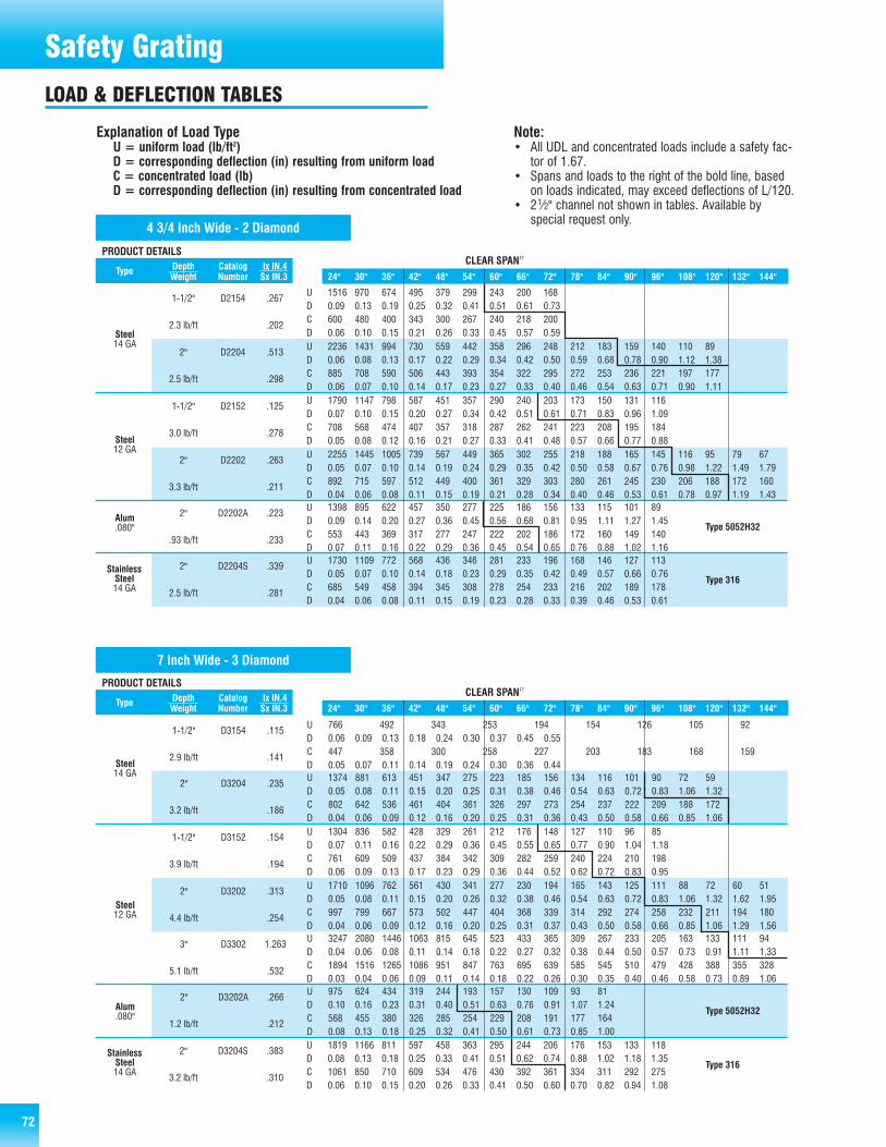
72 72
Safety GratingLOAD & DEFLECTION TABLES
PRODUCT DETAILSDepth Catalog lx lN.4 LoadType Weight Number Sx IN.3 Type 24" 30" 36" 42" 48" 54" 60" 66" 72" 78" 84" 90" 96" 108" 120" 132" 144"
CLEAR SPANFT
4 3/4 Inch Wide - 2 Diamond
1-1/2" D2154 .267U 1516 970 674 495 379 299 243 200 168 D 0.09 0.13 0.19 0.25 0.32 0.41 0.51 0.61 0.73
2.3 lb/ft .202C 600 480 400 343 300 267 240 218 200 D 0.06 0.10 0.15 0.21 0.26 0.33 0.45 0.57 0.59
2" D2204 .513U 2236 1431 994 730 559 442 358 296 248 212 183 159 140 110 89D 0.06 0.08 0.13 0.17 0.22 0.29 0.34 0.42 0.50 0.59 0.68 0.78 0.90 1.12 1.38
2.5 lb/ft .298C 885 708 590 506 443 393 354 322 295 272 253 236 221 197 177D 0.06 0.07 0.10 0.14 0.17 0.23 0.27 0.33 0.40 0.46 0.54 0.63 0.71 0.90 1.11
1-1/2" D2152 .125U 1790 1147 798 587 451 357 290 240 203 173 150 131 116D 0.07 0.10 0.15 0.20 0.27 0.34 0.42 0.51 0.61 0.71 0.83 0.96 1.09
3.0 lb/ft .278C 708 568 474 407 357 318 287 262 241 223 208 195 184D 0.05 0.08 0.12 0.16 0.21 0.27 0.33 0.41 0.48 0.57 0.66 0.77 0.88
2" D2202 .263U 2255 1445 1005 739 567 449 365 302 255 218 188 165 145 116 95 79 67D 0.05 0.07 0.10 0.14 0.19 0.24 0.29 0.35 0.42 0.50 0.58 0.67 0.76 0.98 1.22 1.49 1.79
3.3 lb/ft .211C 892 715 597 512 449 400 361 329 303 280 261 245 230 206 188 172 160D 0.04 0.06 0.08 0.11 0.15 0.19 0.21 0.28 0.34 0.40 0.46 0.53 0.61 0.78 0.97 1.19 1.43
2" D2202A .223U 1398 895 622 457 350 277 225 186 156 133 115 101 89
D 0.09 0.14 0.20 0.27 0.36 0.45 0.56 0.68 0.81 0.95 1.11 1.27 1.45
.93 lb/ft .233C 553 443 369 317 277 247 222 202 186 172 160 149 140
D 0.07 0.11 0.16 0.22 0.29 0.36 0.45 0.54 0.65 0.76 0.88 1.02 1.16
2" D2204S .339U 1730 1109 772 568 436 346 281 233 196 168 146 127 113
D 0.05 0.07 0.10 0.14 0.18 0.23 0.29 0.35 0.42 0.49 0.57 0.66 0.76
2.5 lb/ft .281C 685 549 458 394 345 308 278 254 233 216 202 189 178D 0.04 0.06 0.08 0.11 0.15 0.19 0.23 0.28 0.33 0.39 0.46 0.53 0.61
Steel12 GA
Alum.080"
StainlessSteel14 GA
Type 5052H32
Type 316
Steel14 GA
Explanation of Load TypeU = uniform load (lb/ft2)D = corresponding deflection (in) resulting from uniform loadC = concentrated load (lb)D = corresponding deflection (in) resulting from concentrated load
Note:• All UDL and concentrated loads include a safety fac-
tor of 1.67.• Spans and loads to the right of the bold line, based
on loads indicated, may exceed deflections of L/120.• 21⁄2" channel not shown in tables. Available by
special request only.
7 Inch Wide - 3 Diamond
CLEAR SP AN FT PRODUCT DET AILS
Depth Catalog lx lN.4 L oad Type We ight Number Sx IN.3 T ype 24" 30" 36" 42" 48" 54" 60" 66" 72" 78" 84" 90" 96" 108" 120" 132" 144"
1-1/2" D3154 .115 U 766 492 343 253 194 154 126 105 92 D 0 .06 0 .09 0 .13 0 .1 8 0 .24 0 .30 0 .37 0 .45 0 .55
2.9 lb/f t . 141 C 447 358 300 258 227 203 183 168 159 D 0 .05 0 .07 0 .11 0 .1 4 0 .19 0 .24 0 .30 0 .36 0 .44
2" D3204 .235 U 1374 881 613 451 347 275 223 185 156 134 116 101 90 72 59 D 0 .05 0 .08 0 .11 0 .1 5 0 .20 0 .25 0 .31 0 .38 0 .46 0 .54 0 .63 0 .72 0 .83 1 .06 1 .32
3.2 lb/f t . 186 C 802 642 536 461 404 361 326 297 273 254 237 222 209 188 172 D 0 .04 0 .06 0 .09 0 .1 2 0 .16 0 .20 0 .25 0 .31 0 .36 0 .43 0 .50 0 .58 0 .66 0 .85 1 .06
1-1/2" D3152 .154 U 1304 836 582 428 329 261 212 176 148 127 110 96 85 D 0 .07 0 .11 0 .16 0 .2 2 0 .29 0 .36 0 .45 0 .55 0 .65 0 .77 0 .90 1 .04 1 .18
3.9 lb/f t . 194 C 761 609 509 437 384 342 309 282 259 240 224 210 198 D 0 .06 0 .09 0 .13 0 .1 7 0 .23 0 .29 0 .36 0 .44 0 .52 0 .62 0 .72 0 .83 0 .95
2" D3202 .313 U 1710 1096 762 561 430 341 277 230 194 165 143 125 111 88 72 60 51
D 0 .05 0 .08 0 .11 0 .1 5 0 .20 0 .26 0 .32 0 .38 0 .46 0 .54 0 .63 0 .72 0 .83 1 .06 1 .32 1 .62 1 .9 5
4.4 lb/f t . 254 C 997 799 667 573 502 447 404 368 339 314 292 274 258 232 211 194 180 D 0 .04 0 .06 0 .09 0 .1 2 0 .16 0 .20 0 .25 0 .31 0 .37 0 .43 0 .50 0 .58 0 .66 0 .85 1 .06 1 .29 1 .5 6
2" D3202A .266 U 975 624 434 319 244 193 157 130 109 93 81
D 0 .10 0 .16 0 .23 0 .3 1 0 .40 0 .51 0 .63 0 .76 0 .91 1 .07 1 .24
1.2 lb/f t . 212 C 568 455 380 326 285 254 229 208 191 177 164
D 0 .08 0 .13 0 .18 0 .2 5 0 .32 0 .41 0 .50 0 .61 0 .73 0 .85 1 .00
2" D3204S .383 U 1819 1166 811 597 458 363 295 244 206 176 153 133 118
D 0 .08 0 .13 0 .18 0 .25 0 .33 0 .41 0 .5 1 0 .62 0 .74 0 .88 1 .02 1 .18 1 .35
3.2 lb/f t . 310 C 1061 850 710 609 534 476 430 392 361 334 311 292 275
D 0 .06 0 .10 0 .15 0 .20 0 .26 0 .33 0 .4 1 0 .50 0 .6 0 0 .70 0 .82 0 .94 1 .08
Steel 14 GA
Steel 12 GA
Alum .080"
Stainless Steel 14 GA
3" D3302 1.263
U 3247 2080 1446 1063 815 645 523 433 365 309 267 233 205 163 133 111 94 D 0 .04 0 .06 0 .08 0 .1 1 0 .14 0 .18 0 .22 0 .27 0 .32 0 .38 0 .44 0 .50 0 .57 0 .73 0 .91 1 .11 1 .3 3
5.1 lb/f t . 532 C 1894 1516 1265 1086 951 847 763 695 639 585 545 510 479 428 388 355 328 D 0 .03 0 .04 0 .06 0 .0 9 0 .11 0 .14 0 .18 0 .22 0 .26 0 .30 0 .35 0 .40 0 .46 0 .58 0 .73 0 .89 1 .0 6
Type 5052H32
Type 316

73
Safety GratingLOAD & DEFLECTION TABLES
PRODUCT DET AILS Depth Catalog lx lN.4 L oad Type We ight Number Sx IN.3 T ype 24" 30" 36" 42" 48" 54" 60" 66" 72" 78" 84" 90" 96" 108" 120" 132" 144"
9 1/2 Inch Wide - 4 Diamond
CLEAR SP AN FT
1-1/2" D4154 .128 U 779 499 346 255 195 154 125 103 87 D 0 .09 0 .12 0 .19 0 .26 0 .3 3 0 .41 0 .52 0 .62 0 .74
3.5 lb/f t . 170 C 617 494 411 353 309 274 247 224 206 D 0 .06 0 .10 0 .15 0 .20 0 .2 7 0 .33 0 .41 0 .50 0 .60
2" D4204 .264 U 1063 681 474 349 268 213 173 144 121 104 90 79 70 56 46 D 0 .05 0 .08 0 .12 0 .16 0 .2 1 0 .26 0 .33 0 .40 0 .47 0 .56 0 .65 0 .7 5 0 .86 1 .10 1 .38
3.7 lb/f t . 224 C 841 674 563 484 425 379 342 312 288 267 249 234 221 199 181 D 0.04 0 .06 0 .09 0 .13 0 .1 7 0 .21 0 .26 0 .32 0 .38 0 .45 0 .52 0 .6 0 0 .69 0 .88 1 .10
1-1/2" D4152 .172 U 988 634 441 325 249 198 161 133 113 96 84 73 65 D 0 .08 0 .12 0 .17 0 .23 0 .3 0 0 .39 0 .48 0 .58 0 .69 0 .82 0 .95 1 .1 0 1 .26
4.8 lb/f t . 225 C 782 627 524 450 395 352 318 291 268 248 232 218 205 D 0 .06 0 .09 0 .14 0 .19 0 .2 4 0 .31 0 .38 0 .46 0 .55 0 .65 0 .76 0 .8 8 1 .01
2" D4202 .354 U 1382 886 616 453 348 276 224 186 157 134 116 101 90 72 59 49 42
D 0 .05 0 .08 0 .12 0 .16 0 .2 1 0 .27 0 .34 0 .41 0 .49 0 .57 0 .67 0 .7 7 0 .88 1 .13 1 .41 1 .72 2 .0 8
5.1 lb/f t . 306 C 1094 876 732 628 551 491 443 404 372 345 321 301 284 255 232 213 198 D 0.04 0 .07 0 .10 0 .13 0 .1 7 0 .22 0 .27 0 .33 0 .39 0 .46 0 .54 0 .6 2 0 .71 0 .89 1 .13 1 .38 1 .6 6
2" D4202A .300 U 800 512 356 261 200 158 128 106 89 76 65 57 50
D 0 .12 0 .19 0 .27 0 .37 0 .5 0 0 .62 0 .76 0 .94 1 .12 1 .30 1 .49 1 .7 3 1 .97
1.4 lb/f t . 256 C 633 507 422 362 317 282 253 230 211 195 181 169 158
D 0 .10 0 .16 0 .23 0 .30 0 .4 0 0 .49 0 .62 0 .74 0 .88 1 .04 1 .21 1 .3 8 1 .57
2" D4206S .143 U 750 480 330 240 186 147 120 99 82 70 58 47 39 27
D 0 .06 0 .09 0 .13 0 .18 0 .2 4 0 .30 0 .37 0 .45 0 .53 0 .63 0 .70 0 .7 5 0 .80 0 .90
3.2 lb/f t . 165 C 455 455 398 341 299 265 239 217 199 184 171 159 149 133 D 0 .04 0 .07 0 .11 0 .15 0 .1 9 0 .24 0 .30 0 .36 0 .43 0 .51 0 .59 0 .6 7 0 .76 0 .97
Steel 14 GA
Steel 12 GA
Alum .080"
Stainless Steel 16 GA
3" D4302 1.363
U 2270 1453 1009 741 567 548 444 367 308 263 226 197 173 137 111 92 77 D 0 .04 0 .06 0 .08 0 .11 0 .1 4 0 .22 0 .28 0 .33 0 .40 0 .47 0 .54 0 .6 2 0 .70 0 .89 1 .10 1 .35 1 .6 0
5.8 lb/f t . 605 C 1355 1355 1355 1255 1098 976 878 799 732 676 627 586 549 488 439 399 366 D 0 .02 0 .04 0 .07 0 .11 0 .1 5 0 .18 0 .22 0 .27 0 .32 0 .38 0 .43 0 .4 9 0 .56 0 .71 0 .89 1 .04 1 .2 7
Type 5052H32
Ty pe 304
2" D4204S .401 U 1540 887 687 506 388 307 250 207 175 149 129 113 100 80
D 0 .07 0 .11 0 .16 0 .22 0 .2 8 0 .36 0 .44 0 .54 0 .64 0 .76 0 .88 1 .0 2 1 .17 1 .49
3.7 lb/f t . 287 C 915 915 816 700 614 548 494 451 415 384 358 336 316 284 D 0 .04 0 .08 0 .13 0 .17 0 .2 3 0 .29 0 .36 0 .43 0 .52 0 .61 0 .71 0 .8 2 0 .93 1 .19
Stainless Steel 14 GA
Ty pe 316
PRODUCT DET AILS Depth Catalog lx lN.4 L oad Type We ight Number Sx IN.3 T ype 24" 30" 36" 42" 48" 54" 60" 66" 72" 78" 84" 90" 96" 108" 120" 132" 144"
CLEAR SP AN FT
11 3/4 Inch Wide - 5 Diamond
1-1/2" D5154 .146 U 543 349 243 179 138 110 89 74 63 D 0 .06 0 .1 0 0 .15 0 .20 0 .26 0 .3 3 0 .41 0 .50 0 .60
4.1 lb/f t . 178 C 493 427 357 307 270 242 219 201 185 D 0 .05 0 .0 8 0 .12 0 .16 0 .21 0 .2 7 0 .33 0 .40 0 .48
2" D5204 .314 U 895 574 400 295 226 179 146 121 102 87 75 65 57 45 D 0 .05 0 .0 8 0 .12 0 .16 0 .21 0 .2 7 0 .34 0 .41 0 .49 0 .57 0 .66 0 .76 0 .86 1 .0 9
4.5 lb/f t . 247 C 493 493 493 493 443 395 357 326 299 276 259 239 224 199 D 0 .02 0 .0 5 0 .08 0 .13 0 .17 0 .2 2 0 .27 0 .33 0 .39 0 .46 0 .53 0 .60 0 .69 0 .8 7
1-1/2" D5152 .195 U 842 540 376 276 212 168 137 113 95 82 71 62 55 D 0 .08 0 .1 3 0 .18 0 .25 0 .32 0 .4 1 0 .51 0 .62 0 .73 0 .87 1 .01 1 .16 1 .33
5.7 lb/f t . 244 C 815 661 552 474 415 370 334 305 280 260 242 227 214 D 0 .06 0 .1 0 0 .14 0 .20 0 .26 0 .3 3 0 .41 0 .49 0 .59 0 .69 0 .81 0 .93 1 .06
2" D5202 .419 U 1243 797 554 408 313 248 200 166 139 119 102 89 78 62 50 41
D 0 .06 0 .0 9 0 .13 0 .18 0 .23 0 .2 9 0 .36 0 .44 0 .52 0 .61 0 .72 0 .82 0 .92 1 .1 9 1 .44 1 .75
6.1 lb/f t . 338 C 815 815 814 699 613 545 491 446 409 378 351 327 307 273 245 223 D 0 .03 0 .0 6 0 .10 0 .14 0 .19 0 .2 4 0 .29 0 .35 0 .41 0 .49 0 .57 0 .65 0 .75 0 .9 4 1 .15 1 .41
2" D5202A .355 U 715 457 319 233 179 141 114 94 79 68 58 51 45
D 0 .15 0 .2 3 0 .33 0 .45 0 .58 0 .7 4 0 .90 1 .10 1 .32 1 .54 1 .77 2 .07 2 .38
1.6 lb/f t . 283 C 362 362 362 362 350 311 280 254 233 215 200 187 175
D 0 .06 0 .1 2 0 .21 0 .32 0 .46 0 .6 0 0 .74 0 .88 1 .05 1 .23 1 .44 1 .65 1 .88
2" D5206S .143 U 606 426 296 218 167 132 107 88 74 63 54 48 41 29
D 0 .05 0 .0 8 0 .11 0 .16 0 .21 0 .2 6 0 .32 0 .38 0 .46 0 .53 0 .63 0 .73 0 .80 0 .9 0
3.7 lb/f t . 165 C 376 376 376 376 333 296 266 242 222 205 190 178 166 148 D 0 .02 0 .0 4 0 .07 0 .10 0 .16 0 .2 1 0 .25 0 .31 0 .37 0 .43 0 .50 0 .57 0 .65 0 .8 2
Steel 14 GA
Steel 12 GA
Alum .080"
Stainless Steel 16 GA
3" D5302 1.672
U 1666 1363 946 695 532 421 341 282 237 202 174 151 133 105 85 70 59 D 0 .03 0 .0 7 0 .10 0 .13 0 .18 0 .2 3 0 .28 0 .34 0 .40 0 .47 0 .55 0 .63 0 .71 0 .9 0 1 .13 1 .34 1 .60
6.7 lb/f t . 702 C 815 815 815 815 815 815 815 758 695 642 596 556 521 463 417 379 347 D 0 .01 0 .0 3 0 .05 0 .07 0 .11 0 .1 6 0 .22 0 .27 0 .32 0 .38 0 .43 0 .50 0 .57 0 .7 3 0 .89 1 .07 1 .29
Ty pe 5052H32
Type 304
2" D5204S .427 U 1276 812 565 416 319 253 206 171 144 123 107 93 82 66
D 0 .09 0 .1 4 0 .20 0 .27 0 .36 0 .4 6 0 .56 0 .69 0 .82 0 .97 1 .13 1 .30 1 .48 1 .9 0
4.5 lb/f t . 313 C 899 899 830 713 625 557 503 459 423 392 365 343 323 290 D 0 .05 0 .1 0 0 .16 0 .22 0 .29 0 .3 6 0 .45 0 .55 0 .66 0 .77 0 .90 1 .04 1 .19 1 .5 2
Stainless Steel 14 GA
Type 316

74
Safety GratingLOAD & DEFLECTION TABLES
PRODUCT DE TA ILS CLEAR SP AN FT
Depth Catalog lx lN.4 L oad Type We ight Number Sx IN.3 T ype 24" 30" 36" 42" 48" 54" 60" 66" 72" 78" 84" 90" 96" 108" 120" 132" 144"
18 3/4 Inch Wide - 8 Diamond
1-1/2" D8154 .178 U 411 263 182 134 103 81 66 54 46 D 0 .0 8 0 .11 0 .18 0 .24 0 .3 1 0 .39 0 .49 0 .58 0 .70
5.9 lb/f t . 216 C 555 513 428 365 321 285 257 233 214 D 0 .0 6 0 .10 0 .14 0 .19 0 .2 5 0 .31 0 .38 0 .47 0 .55
2" D8204 .347 U 606 388 269 198 152 120 97 80 67 57 49 43 38 D 0 .0 6 0 .08 0 .12 0 .16 0 .2 1 0 .27 0 .33 0 .39 0 .48 0 .5 6 0 .64 0 .73 0 .84
6.1 lb/f t . 319 C 555 555 555 541 474 421 379 245 316 292 271 253 237 D 0 .0 2 0 .05 0 .08 0 .13 0 .1 7 0 .21 0 .27 0 .32 0 .38 0 .4 5 0 .52 0 .60 0 .67
1-1/2" D8152 .240 U 553 354 246 181 138 109 89 73 61 53 46 40 D 0 .0 7 0 .11 0 .17 0 .23 0 .3 0 0 .38 0 .48 0 .58 0 .68 0 .8 0 0 .94 1 .09
8.2 lb/f t . 291 C 818 691 576 494 432 384 346 314 288 267 250 235 D 0 .0 6 0 .09 0 .14 0 .19 0 .2 5 0 .31 0 .38 0 .46 0 .54 0 .6 4 0 .75 0 .87
2" D8202 .473 U 825 528 367 269 206 163 132 109 92 78 67 59 52 41
D 0 .0 6 0 .09 0 .12 0 .17 0 .2 3 0 .29 0 .35 0 .43 0 .51 0 .5 9 0 .68 0 .79 0 .90 1 .14
8.5 lb/f t . 434 C 818 818 818 737 644 573 516 496 430 397 368 344 322 286 D 0 .0 3 0 .06 0 .09 0 .13 0 .1 8 0 .23 0 .28 0 .33 0 .40 0 .4 7 0 .55 0 .63 0 .71 0 .90
3" D8302 1.245 U 1047 942 654 480 368 291 235 195 163 139 120 105 92 73 59 49 41
D 0 .0 3 0 .06 0 .10 0 .13 0 .1 8 0 .22 0 .27 0 .33 0 .39 0 .4 5 0 .53 0 .61 0 .69 0 .88 1 .07 1 .31 1 .55
9.3 lb/f t . 774 C 818 818 818 818 818 818 818 818 766 707 657 613 575 511 460 418 383 D 0.0 1 0 .02 0 .04 0 .07 0 .1 0 0 .14 0 .19 0 .26 0 .31 0 .3 6 0 .42 0 .48 0 .56 0 .70 0 .87 1 .05 1 .24
2" D8200A .573 U 514 329 229 168 129 102 83 69 58 49 D 0 .1 6 0 .25 0 .36 0 .48 0 .6 1 0 .79 0 .97 1 .18 1 .40 1 .6 5
2.7 lb/f t . 525 C 537 537 537 460 402 353 323 299 269 249 D 0 .0 9 0 .15 0 .28 0 .39 0 .5 0 0 .63 0 .78 0 .93 1 .12 1 .3 1
Steel 12 GA
Alum .100" Type 5052H32
Steel 14 GA
PRODUCT DET AILS Depth Catalog lx lN.4 L oad Type We ight Number Sx IN.3 T ype 24" 30" 36" 42" 48" 54" 60" 66" 72" 78" 84" 90" 96" 108" 120" 132" 144"
CLEAR SP AN FT
24 Inch Wide - 10 Diamond
Steel 14 GA
1-1/2" D10154 .221 U 367 235 163 120 92 72 59 49 41 35 30
D 0 .09 0 .14 0 .20 0 .27 0 .34 0 .44 0 .5 6 0 .66 0 .79 2 .70 3 .11
7.3 lb/f t . 247 C 571 571 489 419 367 326 293 267 245 226 210 D 0 .06 0 .10 0 .15 0 .21 0 .28 0 .35 0 .4 4 0 .53 0 .62 2 .16 2 .51
2" D10204 .427 U 539 345 240 176 135 106 86 71 60 51.00 44 38 34 27 D 0 .05 0 .09 0 .13 0 .17 0 .23 0 .29 0 .3 5 0 .43 0 .51 0 .60 0 .69 0 .78 0 .90 1 .18
7.6 lb/f t . 363 C 571 571 571 571 539 479 431 392 359 332 308 287 270 240 D 0 .02 0 .05 0 .08 0 .12 0 .18 0 .24 0 .2 9 0 .35 0 .41 0 .48 0 .55 0 .64 0 .72 0 .92
1-1/2" D10152 .299 U 496 317 220 162 124 98 79 66 55 47 D 0 .08 0 .13 0 .18 0 .25 0 .32 0 .41 0 .5 0 0 .61 0 .72 0 .86
10.1 lb/f t . 334 C 861 794 661 567 496 441 397 361 332 305 D 0 .05 0 .10 0 .14 0 .20 0 .26 0 .33 0 .4 1 0 .49 0 .58 0 .68
2" D10202 .584 U 738 472 328 241 185 146 118 98 82 70 60 52 46
D 0 .06 0 .09 0 .14 0 .18 0 .23 0 .30 0 .3 6 0 .45 0 .54 0 .63 0 .72 0 .82 1 .22
10.8 lb/f t . 497 C 861 861 861 843 738 656 590 537 492 454 422 394 369 D 0 .03 0 .06 0 .09 0 .14 0 .18 0 .24 0 .2 9 0 .36 0 .42 0 .50 0 .57 0 .67 0 .76
3" D10302 1.513 U 861 835 580 426 326 258 209 173 145 124 107 93 82 64 52 43 36
D 0 .03 0 .07 0 .10 0 .14 0 .18 0 .22 0 .2 8 0 .33 0 .40 0 .47 0 .55 0 .63 0 .71 0 .89 1 .09 1 .34 1 .6 1
11.3 lb/f t . 879 C 861 861 861 861 861 861 861 861 861 803 746 696 653 580 522 475 435 D 0 .01 0 .02 0 .04 0 .06 0 .09 0 .13 0 .1 8 0 .24 0 .31 0 .37 0 .44 0 .50 0 .57 0 .72 0 .88 1 .08 1 .2 8
Steel 12 GA
Note:
• Strut deflection may become a limiting factor on 18" and 24" widths resulting in lower load values as indicated in tables.• Web stiffeners can be supplied for ends and junctions of planks to even deflection if required.

7575
Safety GratingDIAMOND-GRIP® WALKWAY
PRODUCT DESCRIPTIONDiamond-Grip® walkway is a one-piece metal plank grating manufacturedby a cold forming process in the shape of an inverted channel. The web ofthe channel is the walking surface and has rough serrated edges arounddiamond shaped openings. Diamond openings are complete with radiusedcorners at the saddle and side channel location. The extended flanges sup-port the load and provide a built in kickplate (toeboard).
FEATURES & BENEFITS• Serrated edges around diamond shaped openings provide slip
resistance under slippery conditions such as snow, ice, grease, oil, etc.• Radiused corners reduce the possibility of stress cracks across
saddles or at the side of channels under various loading conditions.• Self-cleaning due to resilience of walking surface.• One-piece metal construction complete with a full height toeboard on
each side of the walking surface.• Lightweight design provides high strength to weight ratio.• Long life span requiring little maintenance.• Simple and economical installation as walkways are self-framing.• Adaptable to cost effective custom fabrication.
MATERIAL SPECIFICATIONSGrating shall be “Diamond-Grip® walkway,” manufactured from (see‘Selections’ below) and complete with an (4-1⁄2", 5") integral toeboard,by AMICO.
• SELECTIONS• ASTM-A-653, G-90 (Z-275) pre-galvanized 14 or 12 gauge steel.• ASTM-A-1011, HRP&O 14 or 12 gauge steel.

76 76
Safety GratingDIAMOND-GRIP® WALKWAY
PRODUCT DET AILS Depth Catalog lx lN.4 L oad Type We ight Number Sx IN.3 T ype 24" 30" 36" 42" 48" 54" 60" 66" 72" 78" 84" 90" 96" 108" 120" 132" 144"
CLEAR SP AN FT
4-1/2" D10452W 2.457 U 475 475 475 475 475 429 348 287 240 203 177 150 135 107 87 71 60
D 0 .45 0 .4 6 0 .47 0 .49 0 .52 0 .5 1 0 .47 0 .43 0 .42 0 .4 1 0 .43 0 .43 0 .48 0 .5 4 0 .62 0 .7 2 0 .84
12.5 lb/f t 1 .171 C 475 475 475 475 475 475 475 475 475 475 475 475 475 475 475 475 475
D 0 .36 0 .3 6 0 .36 0 .36 0 .36 0 .3 9 0 .41 0 .43 0 .44 0 .4 6 0 .49 0 .51 0 .54 0 .6 0 0 .70 0 .8 1 0 .95
4-1/2" D10454W 1.447 U 300 300 300 300 300 263 213 176 145 124 110 94 84 67 55 44 37 D 0 .50 0 .5 1 0 .52 0 .55 0 .58 0 .5 5 0 .49 0 .46 0 .45 0 .4 3 0 .47 0 .46 0 .51 0 .5 8 0 .67 0 .7 5 0 .87
8.9 lb/f t . 776 C 300 300 300 300 300 300 300 300 300 300 300 300 300 300 300 300 300
D 0 .40 0 .4 0 0 .40 0 .41 0 .42 0 .4 3 0 .44 0 .46 0 .48 0 .5 0 0 .53 0 .56 0 .60 0 .6 9 0 .80 0 .9 5 1 .10
5" D10504W 1.929 U 300 300 300 300 300 263 213 176 145 124 110 94 84 67 55 44 37
D 0 .50 0 .5 0 0 .52 0 .54 0 .56 0 .5 5 0 .46 0 .42 0 .39 0 .3 8 0 .40 0 .39 0 .42 0 .4 7 0 .53 0 .5 8 0 .67
9.6 lb/f t . 917 C 300 300 300 300 300 300 300 300 300 300 300 300 300 300 300 300 300
D 0 .40 0 .4 0 0 .40 0 .40 0 .41 0 .4 2 0 .43 0 .45 0 .46 0 .4 8 0 .50 0 .52 0 .55 0 .6 2 0 .70 0 .8 2 0 .97
5" D10502W 3.247 U 475 475 475 475 475 429 348 287 240 203 177 150 135 107 87 71 60
D 0 .45 0 .4 6 0 .46 0 .48 0 .50 0 .4 9 0 .44 0 .39 0 .37 0 .3 6 0 .37 0 .36 0 .39 0 .4 3 0 .49 0 .5 6 0 .65
13.1 lb/f t 1 .385 C 475 475 475 475 475 475 475 475 475 475 475 475 475 475 475 475 475
D 0 .36 0 .3 6 0 .36 0 .36 0 .37 0 .3 8 0 .40 0 .41 0 .42 0 .4 3 0 .44 0 .47 0 .49 0 .5 5 0 .61 0 .6 9 0 .80
24" Wide 12 GA
24" Wide 12 GA
24" Wide 14 GA
24" Wide 14 GA
Explanation of Load TypeU = uniform load (lb/ft2)D = corresponding deflection (in) resulting from uniform loadC = concentrated load (lb)D = corresponding deflection (in) resulting from concentrated load
Note:• All UDL and concentrated loads include a safety factor
of 1.67.• Strut deflection may become a limiting factor resulting in
lower load values as indicated in table.
Note:
• Tolerances on all dimensions are ±1/8"• Standard lengths are 121 1⁄2" & 144".• Tolerance on manufactured and cut lengths is ±1/8".• When cutting Diamond-Grip®, AMICO® recommends cutting to full or half diamond increments.• Camber is an expected condition with sheet metal products. While ASTM allowance is generous, AMICO attempts to lessen the
effects. Normal clearances should offset this phenomenon, however where tolerances warrant, contact AMICO for clarification.
TECHNICALDETAILS

77
SAFETY-GRIP®
77
Safety Grating
PRODUCT DESCRIPTIONSafety-Grip® is a one-piece metal plank grating manufactured by a coldforming process in the shape of a channel. The web of the channel is thewalking surface and has large debossed holes, surrounded by smallerembossed traction buttons.
FEATURES & BENEFITS• Embossed traction buttons provide superior slip resistance in all
directions and in all weather conditions.• Large debossed holes provide maximum drainage of debris and allow
up to 50% free air opening depending on channel width.• Self-cleaning due to resilience of walking surface.• One-piece metal construction.• Lightweight design provides high strength to weight ratio.• Long life span requiring little maintenance.• Simple and economical installation as planks are self-framing.• Adaptable to cost effective custom fabrication.• Can be easily formed in standard channel or custom shapes.
MATERIAL SPECIFICATIONSGrating shall be “Safety-Grip® channel,” manufactured from (see‘Selections’ below) and complete with a (1-1/2", 2", 3") side channeldepth, by AMICO.
• SELECTIONS• ASTM-A-653, G-90 (Z-275) Pre-galvanized 13 or 11 gauge steel.• ASTM-A-1011, HRP&O 13 or 11 gauge steel.• 5052H32 Aluminum .125" thick (up to 18" width).• Type 316L 2B Stainless Steel 14 gauge (up to 12" width).• Type 304L 2B Stainless Steel 16 gauge (up to 12" width).
Note:
1. Tolerances on all dimensions are ±1/8"2. End-hole pattern shown on diagram is even. Widths
indicated with ** have a staggered end-hole pattern.3. Outside traction buttons on all widths except 18" & 24" width.4. Standard lengths are 120" and 144".5. Tolerance on manufactured and cut lengths is ±1/8".6. Camber is an expected condition with sheet metal products. While ASTM allowance is generous, AMICO attempts to lessen the
effects. Normal clearances should offset this phenomenon, however where tolerances warrant, contact AMICO for clarification.
CHANNEL RETURN CL HOLEWIDTH FLANGE CHANNEL
EDGE“A” “B” “C”
**5" 7/8" 1 21/32"**7" 1" 1 13/16"**10" 7/8" 1 5/8"**12" 1" 1 25/32"**18" 1" 1 13/32"**24" 1 1/18" 1 7/8"**30" 1 1/18" 2 11/32"

78 78
Safety GratingLOAD & DEFLECTION TABLES
CLEAR SP AN FT PRODUCT DET AILS
Depth Catalog lx lN.4 L oad Type We ight Number Sx IN.3 T ype 24" 30" 36" 42" 48" 54" 60" 66" 72" 78" 84" 90" 96" 108" 120" 132" 144"
2" S2204S .377 U 3295 2109 1464 1076 824 651 527 436 366 312 269 234
D 0 .05 0 .07 0 .11 0 .15 0 .1 9 0 .24 0 .30 0 .36 0 .43 0 .50 0 .58 0 .6 7
2.5 lb/f t . 312 C 1373 1098 915 784 686 610 549 499 458 422 392 366 D 0 .04 0 .06 0 .09 0 .12 0 .1 5 0 .19 0 .24 0 .29 0 .34 0 .40 0 .47 0 .5 3
Stainless Steel 14 GA
Type 316
5 Inch Wide - 2 Hole
1-1/2" S2153 .228 U 1947 1248 868 639 490 388 315 261 220 188 163 142 126 D 0 .06 0 .10 0 .14 0 .19 0 .2 5 0 .32 0 .39 0 .48 0 .57 0 .67 0 .78 0 .9 0 1 .03
2.6 lb/f t . 247 C 811 650 542 466 408 364 328 299 275 255 237 222 209 D 0 .05 0 .08 0 .11 0 .15 0 .2 0 0 .25 0 .31 0 .38 0 .46 0 .54 0 .62 0 .7 2 0 .82
2" S2203 .449 U 2943 1885 1311 964 739 585 475 393 331 283 245 214 188 150 122 102 86 D 0 .05 0 .08 0 .11 0 .16 0 .2 0 0 .26 0 .32 0 .39 0 .46 0 .54 0 .63 0 .7 3 0 .83 1 .05 1 .31 1 .60 1 .9 2
2.8 lb/f t . 372 C 973 973 819 703 616 549 495 451 414 383 357 334 314 281 255 233 216 D 0 .03 0 .06 0 .09 0 .12 0 .1 6 0 .21 0 .25 0 .31 0 .37 0 .43 0 .50 0 .5 8 0 .66 0 .84 1 .05 1 .28 1 .5 4
2" S2208A .603 U 2479 1587 1102 809 620 490 397 328 275 D 0 .08 0 .12 0 .17 0 .24 0 .3 1 0 .39 0 .49 0 .59 0 .70
1.3 lb/f t . 449 C 1033 826 689 590 516 459 413 379 344 D 0 .06 0 .10 0 .14 0 .19 0 .2 5 0 .32 0 .39 0 .47 0 .56
Alum .125" Type 5052H32
Steel 13 GA
Explanation of Load TypeU = uniform load (lb/ft2)D = corresponding deflection (in) resulting from uniform loadC = concentrated load (lb)D = corresponding deflection (in) resulting from concentrated load
Note:• All uniform and concentrated loads include a safety
factor of 1.67.• Spans and loads to the right of the bold line, based
on loads indicated, may exceed deflections ofL/120.
PRODUCT DET AILS Depth Catalog lx lN.4 L oad Type We ight Number Sx IN.3 T ype 24" 30" 36" 42" 48" 54" 60" 66" 72" 78" 84" 90" 96" 108" 120" 132" 144"
CLEAR SP AN FT
2" S3204S .426 U 2148 1375 955 701 537 424 344 284 239 203 175
D 0 .0 4 0 .06 0 .09 0 .1 2 0 .15 0 .19 0 .24 0 .29 0 .35 0 .41 0 .47
2.8 lb/f t . 348 C 1253 1002 835 716 626 557 501 456 418 385 358
D 0 .0 3 0 .05 0 .07 0 .0 9 0 .12 0 .16 0 .19 0 .23 0 .28 0 .32 0 .38
Stainless Steel 14 GA
Type 316
7 Inch Wide - 3 Hole
1-1/2" S3153 .260 U 1489 954 664 489 375 297 241 200 169 144 125 109 97 D 0 .0 6 0 .09 0 .14 0 .1 9 0 .24 0 .31 0 .38 0 .46 0 .55 0 .65 0 .76 0 .88 1 .0 0
3 lb/f t . 277 C 793 696 581 499 437 390 352 321 295 274 255 239 225 D 0 .0 4 0 .08 0 .11 0 .1 5 0 .19 0 .25 0 .31 0 .37 0 .44 0 .52 0 .61 0 .70 0 .8 0
2" S3203 .509 U 2229 1428 993 731 560 444 360 298 251 215 186 162 143 114 93 D 0 .0 5 0 .08 0 .11 0 .1 5 0 .20 0 .25 0 .31 0 .37 0 .45 0 .52 0 .61 0 .70 0 .8 0 1 .02 1 .27
3.3 lb/f t . 415 C 793 793 793 746 654 582 525 479 440 407 379 355 334 299 271 D 0 .0 2 0 .05 0 .08 0 .1 2 0 .16 0 .20 0 .25 0 .30 0 .36 0 .42 0 .49 0 .56 0 .6 4 0 .82 1 .02
1-1/2" S3151 .330 U 1921 1231 856 630 483 382 310 257 217 185 160 140 124 D 0 .0 6 0 .10 0 .14 0 .1 9 0 .24 0 .31 0 .38 0 .47 0 .56 0 .65 0 .76 0 .88 1 .0 0
4.2 lb/f t . 353 C 1098 897 749 643 564 502 453 413 379 351 327 306 288 D 0 .0 5 0 .08 0 .11 0 .1 5 0 .20 0 .25 0 .31 0 .37 0 .44 0 .52 0 .61 0 .70 0 .8 0
2" S3201 .655 U 2995 1918 1333 981 752 595 483 399 336 293 253 221 195 155 126 105 89
D 0 .0 5 0 .08 0 .12 0 .1 6 0 .21 0 .27 0 .34 0 .41 0 .49 0 .56 0 .62 0 .71 0 .8 1 1 .03 1 .28 1 .56 1 .87
4.5 lb/f t . 534 C 1098 1098 1098 1001 877 781 704 641 586 556 517 484 455 407 368 337 311 D 0 .0 3 0 .05 0 .09 0 .1 3 0 .17 0 .22 0 .27 0 .33 0 .39 0 .44 0 .49 0 .57 0 .6 5 0 .82 1 .02 1 .25 1 .50
2" S3208A .686 U 1984 1270 882 648 496 392 317 262 220 D 0 .0 8 0 .13 0 .19 0 .2 5 0 .33 0 .42 0 .52 0 .63 0 .75
1.5 lb/f t . 559 C 1157 926 771 661 579 514 463 421 386 D 0 .0 6 0 .10 0 .15 0 .2 0 0 .27 0 .34 0 .42 0 .50 0 .60
Steel 13 GA
Steel 11 GA
Alum .125"
3" S3301 1.726
U 3765 3602 2503 1840 1410 1115 904 748 629 537 464 404 356 282 229 190 161 D 0 .0 2 0 .05 0 .08 0 .1 1 0 .14 0 .18 0 .22 0 .26 0 .31 0 .37 0 .43 0 .49 0 .5 6 0 .71 0 .88 1 .07 1 .28
4.8 lb/f t . 966 C 1098 1098 1098 1098 1098 1098 1098 1098 1098 1018 946 885 831 741 669 611 563 D 0 .0 1 0 .02 0 .03 0 .0 5 0 .07 0 .11 0 .14 0 .19 0 .25 0 .29 0 .34 0 .39 0 .4 5 0 .57 0 .70 0 .85 1 .02
Type 5052H32
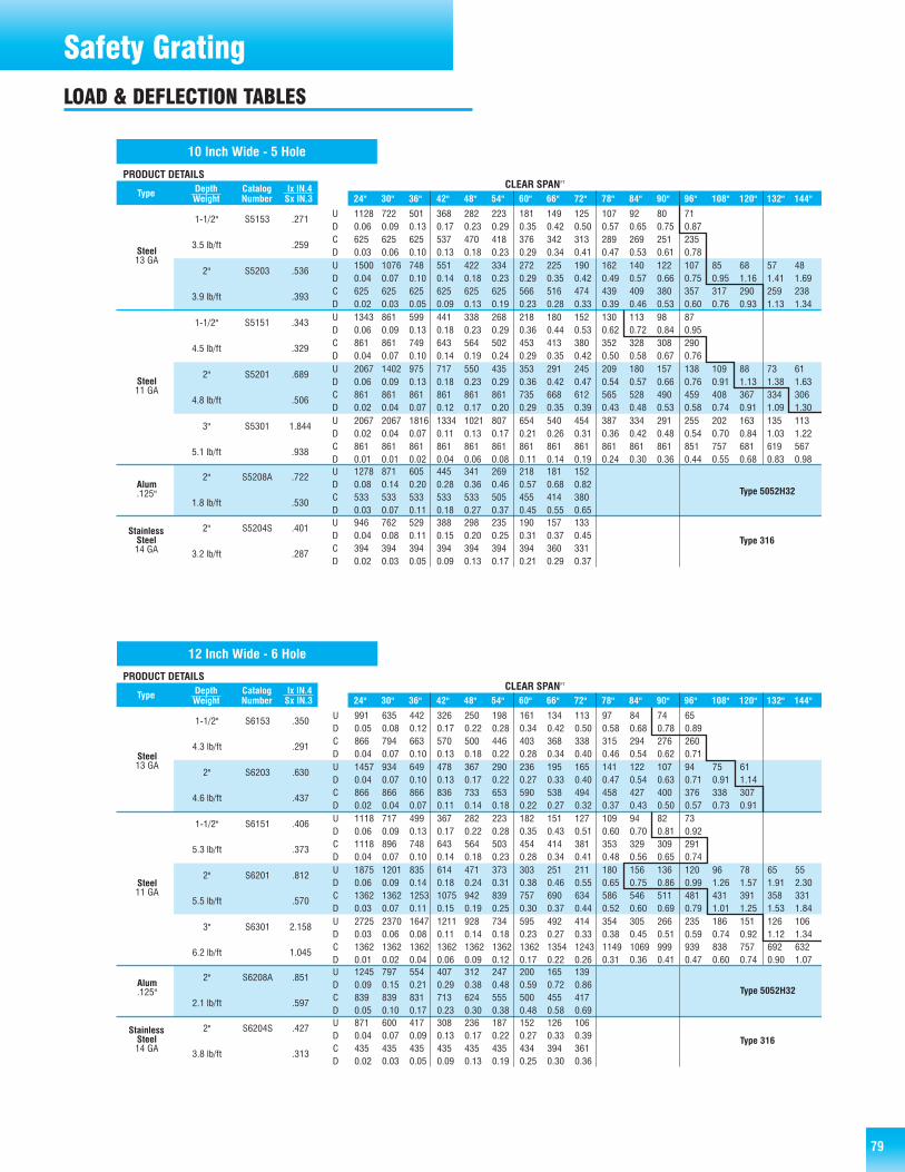
79
Safety GratingLOAD & DEFLECTION TABLES
PRODUCT DETAILSDepth Catalog lx lN.4 LoadType Weight Number Sx IN.3 Type 24" 30" 36" 42" 48" 54" 60" 66" 72" 78" 84" 90" 96" 108" 120" 132" 144"
CLEAR SPANFT
2" S5204S .401U 946 762 529 388 298 235 190 157 133
D 0.04 0.08 0.11 0.15 0.20 0.25 0.31 0.37 0.45
3.2 lb/ft .287C 394 394 394 394 394 394 394 360 331 D 0.02 0.03 0.05 0.09 0.13 0.17 0.21 0.29 0.37
StainlessSteel14 GA
Type 316
10 Inch Wide - 5 Hole
1-1/2" S5153 .271U 1128 722 501 368 282 223 181 149 125 107 92 80 71
D 0.06 0.09 0.13 0.17 0.23 0.29 0.35 0.42 0.50 0.57 0.65 0.75 0.87
3.5 lb/ft .259C 625 625 625 537 470 418 376 342 313 289 269 251 235D 0.03 0.06 0.10 0.13 0.18 0.23 0.29 0.34 0.41 0.47 0.53 0.61 0.78
2" S5203 .536U 1500 1076 748 551 422 334 272 225 190 162 140 122 107 85 68 57 48D 0.04 0.07 0.10 0.14 0.18 0.23 0.29 0.35 0.42 0.49 0.57 0.66 0.75 0.95 1.16 1.41 1.69
3.9 lb/ft .393C 625 625 625 625 625 625 566 516 474 439 409 380 357 317 290 259 238D 0.02 0.03 0.05 0.09 0.13 0.19 0.23 0.28 0.33 0.39 0.46 0.53 0.60 0.76 0.93 1.13 1.34
1-1/2" S5151 .343U 1343 861 599 441 338 268 218 180 152 130 113 98 87D 0.06 0.09 0.13 0.18 0.23 0.29 0.36 0.44 0.53 0.62 0.72 0.84 0.95
4.5 lb/ft .329C 861 861 749 643 564 502 453 413 380 352 328 308 290D 0.04 0.07 0.10 0.14 0.19 0.24 0.29 0.35 0.42 0.50 0.58 0.67 0.76
2" S5201 .689U 2067 1402 975 717 550 435 353 291 245 209 180 157 138 109 88 73 61
D 0.06 0.09 0.13 0.18 0.23 0.29 0.36 0.42 0.47 0.54 0.57 0.66 0.76 0.91 1.13 1.38 1.63
4.8 lb/ft .506C 861 861 861 861 861 861 735 668 612 565 528 490 459 408 367 334 306D 0.02 0.04 0.07 0.12 0.17 0.20 0.29 0.35 0.39 0.43 0.48 0.53 0.58 0.74 0.91 1.09 1.30
3" S5301 1.844
U 2067 2067 1816 1334 1021 807 654 540 454 387 334 291 255 202 163 135 113 D 0.02 0.04 0.07 0.11 0.13 0.17 0.21 0.26 0.31 0.36 0.42 0.48 0.54 0.70 0.84 1.03 1.22
5.1 lb/ft .938C 861 861 861 861 861 861 861 861 861 861 861 861 851 757 681 619 567D 0.01 0.01 0.02 0.04 0.06 0.08 0.11 0.14 0.19 0.24 0.30 0.36 0.44 0.55 0.68 0.83 0.98
2" S5208A .722U 1278 871 605 445 341 269 218 181 152
D 0.08 0.14 0.20 0.28 0.36 0.46 0.57 0.68 0.82
1.8 lb/ft .530C 533 533 533 533 533 505 455 414 380
D 0.03 0.07 0.11 0.18 0.27 0.37 0.45 0.55 0.65
Steel13 GA
Steel11 GA
Alum.125" Type 5052H32
PRODUCT DETAILSDepth Catalog lx lN.4 LoadType Weight Number Sx IN.3 Type 24" 30" 36" 42" 48" 54" 60" 66" 72" 78" 84" 90" 96" 108" 120" 132" 144"
CLEAR SPANFT
2" S6204S .427U 871 600 417 308 236 187 152 126 106
D 0.04 0.07 0.09 0.13 0.17 0.22 0.27 0.33 0.39
3.8 lb/ft .313C 435 435 435 435 435 435 434 394 361D 0.02 0.03 0.05 0.09 0.13 0.19 0.25 0.30 0.36
StainlessSteel14 GA
Type 316
12 Inch Wide - 6 Hole
1-1/2" S6153 .350U 991 635 442 326 250 198 161 134 113 97 84 74 65
D 0.05 0.08 0.12 0.17 0.22 0.28 0.34 0.42 0.50 0.58 0.68 0.78 0.89
4.3 lb/ft .291C 866 794 663 570 500 446 403 368 338 315 294 276 260D 0.04 0.07 0.10 0.13 0.18 0.22 0.28 0.34 0.40 0.46 0.54 0.62 0.71
2" S6203 .630U 1457 934 649 478 367 290 236 195 165 141 122 107 94 75 61D 0.04 0.07 0.10 0.13 0.17 0.22 0.27 0.33 0.40 0.47 0.54 0.63 0.71 0.91 1.14
4.6 lb/ft .437C 866 866 866 836 733 653 590 538 494 458 427 400 376 338 307D 0.02 0.04 0.07 0.11 0.14 0.18 0.22 0.27 0.32 0.37 0.43 0.50 0.57 0.73 0.91
1-1/2" S6151 .406U 1118 717 499 367 282 223 182 151 127 109 94 82 73D 0.06 0.09 0.13 0.17 0.22 0.28 0.35 0.43 0.51 0.60 0.70 0.81 0.92
5.3 lb/ft .373C 1118 896 748 643 564 503 454 414 381 353 329 309 291D 0.04 0.07 0.10 0.14 0.18 0.23 0.28 0.34 0.41 0.48 0.56 0.65 0.74
2" S6201 .812U 1875 1201 835 614 471 373 303 251 211 180 156 136 120 96 78 65 55
D 0.06 0.09 0.14 0.18 0.24 0.31 0.38 0.46 0.55 0.65 0.75 0.86 0.99 1.26 1.57 1.91 2.30
5.5 lb/ft .570C 1362 1362 1253 1075 942 839 757 690 634 586 546 511 481 431 391 358 331D 0.03 0.07 0.11 0.15 0.19 0.25 0.30 0.37 0.44 0.52 0.60 0.69 0.79 1.01 1.25 1.53 1.84
3" S6301 2.158
U 2725 2370 1647 1211 928 734 595 492 414 354 305 266 235 186 151 126 106 D 0.03 0.06 0.08 0.11 0.14 0.18 0.23 0.27 0.33 0.38 0.45 0.51 0.59 0.74 0.92 1.12 1.34
6.2 lb/ft 1.045C 1362 1362 1362 1362 1362 1362 1362 1354 1243 1149 1069 999 939 838 757 692 632D 0.01 0.02 0.04 0.06 0.09 0.12 0.17 0.22 0.26 0.31 0.36 0.41 0.47 0.60 0.74 0.90 1.07
2" S6208A .851U 1245 797 554 407 312 247 200 165 139
D 0.09 0.15 0.21 0.29 0.38 0.48 0.59 0.72 0.86
2.1 lb/ft .597C 839 839 831 713 624 555 500 455 417
D 0.05 0.10 0.17 0.23 0.30 0.38 0.48 0.58 0.69
Steel13 GA
Steel11 GA
Alum.125" Type 5052H32
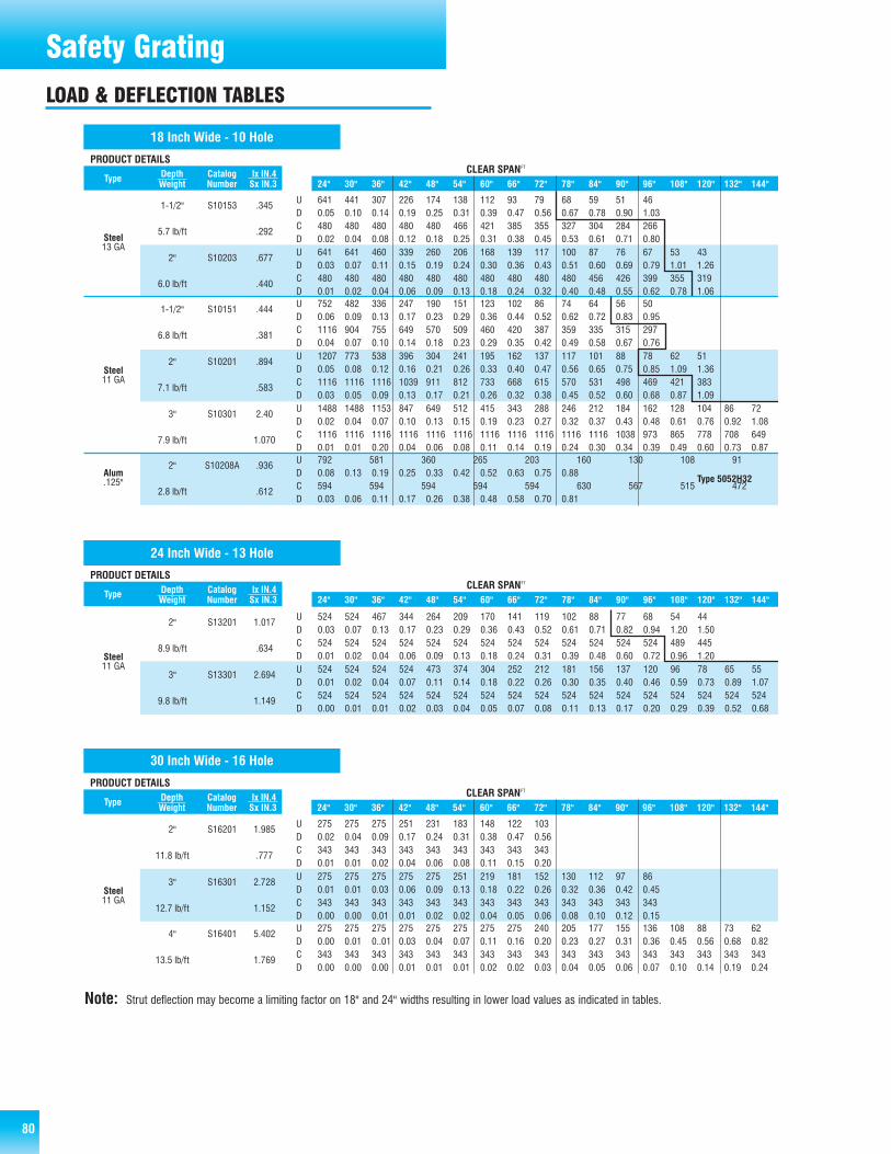
80
Safety GratingLOAD & DEFLECTION TABLES
PRODUCT DET AILS Depth Catalog lx lN.4 L oad Type We ight Number Sx IN.3 T ype 24" 30" 36" 42" 48" 54" 60" 66" 72" 78" 84" 90" 96" 108" 120" 132" 144"
CLEAR SP AN FT
18 Inch Wide - 10 Hole
1-1/2" S10153 .345 U 641 441 307 226 174 138 112 93 79 68 59 51 46
D 0 .0 5 0 .10 0 .14 0 .19 0 .2 5 0 .31 0 .39 0 .47 0 .56 0 .67 0 .78 0 .90 1 .03
5.7 lb/f t . 292 C 480 480 480 480 480 466 421 385 355 327 304 284 266 D 0 .0 2 0 .04 0 .08 0 .12 0 .1 8 0 .25 0 .31 0 .38 0 .45 0 .53 0 .61 0 .71 0 .80
2" S10203 .677 U 641 641 460 339 260 206 168 139 117 100 87 76 67 53 43 D 0 .0 3 0 .07 0 .11 0 .15 0 .1 9 0 .24 0 .30 0 .36 0 .43 0 .51 0 .60 0 .69 0 .79 1 .01 1 .26
6.0 lb/f t . 440 C 480 480 480 480 480 480 480 480 480 480 456 426 399 355 319 D 0.0 1 0 .02 0 .04 0 .06 0 .0 9 0 .13 0 .18 0 .24 0 .32 0 .40 0 .48 0 .55 0 .62 0 .78 1 .06
1-1/2" S10151 .444 U 752 482 336 247 190 151 123 102 86 74 64 56 50 D 0 .0 6 0 .09 0 .13 0 .17 0 .2 3 0 .29 0 .36 0 .44 0 .52 0 .62 0 .72 0 .83 0 .95
6.8 lb/f t . 381 C 1116 904 755 649 570 509 460 420 387 359 335 315 297 D 0 .0 4 0 .07 0 .10 0 .14 0 .1 8 0 .23 0 .29 0 .35 0 .42 0 .49 0 .58 0 .67 0 .76
2" S10201 .894 U 1207 773 538 396 304 241 195 162 137 117 101 88 78 62 51
D 0 .0 5 0 .08 0 .12 0 .1 6 0 .21 0 .26 0 .33 0 .40 0 .47 0 .56 0 .65 0 .75 0 .8 5 1 .09 1 .36
7.1 lb/f t . 583 C 1116 1116 1116 1039 911 812 733 668 615 570 531 498 469 421 383 D 0 .0 3 0 .05 0 .09 0 .1 3 0 .17 0 .21 0 .26 0 .32 0 .38 0 .45 0 .52 0 .60 0 .6 8 0 .87 1 .09
3" S10301 2.40 U 1488 1488 1153 847 649 512 415 343 288 246 212 184 162 128 104 86 72
D 0 .0 2 0 .04 0 .07 0 .1 0 0 .13 0 .15 0 .19 0 .23 0 .27 0 .32 0 .37 0 .43 0 .4 8 0 .61 0 .76 0 .92 1 .08
7.9 lb/f t 1 .070 C 1116 1116 1116 1116 1116 1116 1116 1116 1116 1116 1116 1038 973 865 778 708 649 D 0 .0 1 0 .01 0 .20 0 .0 4 0 .06 0 .08 0 .11 0 .14 0 .19 0 .24 0 .30 0 .34 0 .3 9 0 .49 0 .60 0 .73 0 .87
2" S10208A .936 U 792 581 360 265 203 160 130 108 91 77 D 0 .0 8 0 .13 0 .19 0 .25 0 .3 3 0 .42 0 .52 0 .63 0 .75 0 .88
2.8 lb/f t . 612 C 594 594 594 594 594 630 567 515 472 436 D 0 .0 3 0 .06 0 .11 0 .17 0 .2 6 0 .38 0 .48 0 .58 0 .70 0 .81
Steel 13 GA
Steel 11 GA
Alum .125" Type 5052H32
PRODUCT DETAILSDepth Catalog lx lN.4 LoadType Weight Number Sx IN.3 Type 24" 30" 36" 42" 48" 54" 60" 66" 72" 78" 84" 90" 96" 108" 120" 132" 144"
CLEAR SPANFT
24 Inch Wide - 13 Hole
2" S13201 1.017U 524 524 467 344 264 209 170 141 119 102 88 77 68 54 44D 0.03 0.07 0.13 0.17 0.23 0.29 0.36 0.43 0.52 0.61 0.71 0.82 0.94 1.20 1.50
8.9 lb/ft .634C 524 524 524 524 524 524 524 524 524 524 524 524 524 489 445D 0.01 0.02 0.04 0.06 0.09 0.13 0.18 0.24 0.31 0.39 0.48 0.60 0.72 0.96 1.20
3" S13301 2.694U 524 524 524 524 473 374 304 252 212 181 156 137 120 96 78 65 55
D 0.01 0.02 0.04 0.07 0.11 0.14 0.18 0.22 0.26 0.30 0.35 0.40 0.46 0.59 0.73 0.89 1.07
9.8 lb/ft 1.149C 524 524 524 524 524 524 524 524 524 524 524 524 524 524 524 524 524D 0.00 0.01 0.01 0.02 0.03 0.04 0.05 0.07 0.08 0.11 0.13 0.17 0.20 0.29 0.39 0.52 0.68
Steel11 GA
PRODUCT DET AILS Depth Catalog lx lN.4 L oad Type We ight Number Sx IN.3 T ype 24" 30" 36" 42" 48" 54" 60" 66" 72" 78" 84" 90" 96" 108" 120" 132" 144"
CLEAR SP AN FT
30 Inch Wide - 16 Hole
2" S16201 1.985 U 275 275 275 251 231 183 148 122 103
D 0 .02 0 .04 0 .09 0 .17 0 .24 0 .31 0 .38 0 .47 0 .56
11.8 lb/f t . 777 C 343 343 343 343 343 343 343 343 343 D 0 .01 0 .01 0 .02 0 .04 0 .06 0 .08 0 .11 0 .15 0 .20
3" S16301 2.728 U 275 275 275 275 275 251 219 181 152 130 112 97 86 D 0 .01 0 .01 0 .03 0 .06 0 .09 0 .13 0 .18 0 .22 0 .26 0 .32 0 .36 0 .4 2 0 .45
12.7 lb/f t 1 .152 C 343 343 343 343 343 343 343 343 343 343 343 343 343 D 0 .00 0 .00 0 .01 0 .01 0 .02 0 .02 0 .04 0 .05 0 .06 0 .08 0 .10 0 .1 2 0 .15
4" S16401 5.402 U 275 275 275 275 275 275 275 275 240 205 177 155 136 108 88 73 62
D 0 .00 0 .01 0 ..01 0 .03 0 .04 0 .07 0 .11 0 .16 0 .20 0 .23 0 .27 0 .3 1 0 .36 0 .45 0 .56 0 .68 0 .82
13.5 lb/f t 1 .769 C 343 343 343 343 343 343 343 343 343 343 343 343 343 343 343 343 343 D 0 .00 0 .00 0 .00 0 .01 0 .01 0 .01 0 .02 0 .02 0 .03 0 .04 0 .05 0 .0 6 0 .07 0 .10 0 .14 0 .19 0 .24
Steel 11 GA
Note: Strut deflection may become a limiting factor on 18" and 24" widths resulting in lower load values as indicated in tables.
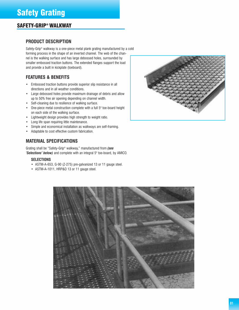
8181
Safety GratingSAFETY-GRIP® WALKWAY
PRODUCT DESCRIPTIONSafety-Grip® walkway is a one-piece metal plank grating manufactured by a coldforming process in the shape of an inverted channel. The web of the chan-nel is the walking surface and has large debossed holes, surrounded bysmaller embossed traction buttons. The extended flanges support the loadand provide a built in kickplate (toeboard).
FEATURES & BENEFITS• Embossed traction buttons provide superior slip resistance in all
directions and in all weather conditions.• Large debossed holes provide maximum drainage of debris and allow
up to 50% free air opening depending on channel width.• Self-cleaning due to resilience of walking surface.• One-piece metal construction complete with a full 5" toe-board height
on each side of the walking surface.• Lightweight design provides high strength to weight ratio.• Long life span requiring little maintenance.• Simple and economical installation as walkways are self-framing.• Adaptable to cost effective custom fabrication.
MATERIAL SPECIFICATIONSGrating shall be “Safety-Grip® walkway,” manufactured from (see‘Selections’ below) and complete with an integral 5" toe-board, by AMICO.
SELECTIONS• ASTM-A-653, G-90 (Z-275) pre-galvanized 13 or 11 gauge steel.• ASTM-A-1011, HRP&O 13 or 11 gauge steel.

82 82
Safety GratingSAFETY-GRIP® WALKWAY
TECHNICALDETAILS
PRODUCT DET AILS Depth Catalog lx lN.4 L oad Type Weight Number Sx IN.3 T ype 24" 30" 36" 42" 48" 54" 60" 66" 72" 78" 84" 90" 96" 108" 120" 132" 144"
CLEAR SP AN FT
5" S13503W 6.610 U 355 355 355 355 355 355 355 355 355 355 346 301 245 209 169 140 118 D 0 .00 0 .00 0 .0 1 0 .02 0 .03 0 .0 5 0 .07 0 .10 0 .1 5 0 .20 0 .2 6 0 .30 0 .35 0 .44 0 .5 3 0 .65 0 .7 8
8.7 lb/f t 2 .078 C 355 355 355 355 355 355 355 355 355 355 355 355 355 355 355 355 355
D 0 .00 0 .00 0 .0 0 0 .00 0 .01 0 .0 1 0 .01 0 .02 0 .0 2 0 .02 0 .0 3 0 .04 0 .05 0 .07 0 .0 9 0 .12 0 .1 6
5" S13501W 9.968 U 657 657 657 657 657 657 657 657 619 528 455 396 348 275 223 104 155 D 0.00 0 .01 0 .0 1 0 .02 0 .03 0 .0 5 0 .08 0 .12 0 .1 6 0 .19 0 .2 2 0 .26 0 .29 0 .37 0 .4 5 0 .54 0 .6 5
11.8 lb/f t 2 .880 C 657 657 657 657 657 657 657 657 657 657 657 657 657 657 657 657 657 D 0 .00 0 .00 0 .0 0 0 .00 0 .01 0 .0 1 0 .01 0 .02 0 .0 2 0 .03 0 .0 4 0 .04 0 .05 0 .08 0 .1 1 0 .14 0 .1 8
5" S16501W 10.090 U 384 384 384 384 384 384 384 384 384 355 306 267 234 185 150 124 104 D 0 .00 0 .01 0 .0 1 0 .02 0 .04 0 .0 6 0 .09 0 .16 0 .2 0 0 .23 0 .2 6 0 .30 0 .34 0 .45 0 .5 5 0 .66 0 .7 8
13.6 lb/f t 2 .889 C 480 480 480 480 480 480 480 480 480 480 480 480 480 480 480 480 480
D 0 .00 0 .00 0 .0 0 0 .00 0 .01 0 .0 1 0 .01 0 .02 0 .0 2 0 .03 0 .0 4 0 .05 0 .06 0 .08 0 .1 1 0 .15 0 .1 9
5" S18501W N/ A U 185 185 185 185 185 185 185 185 185 185 185 185 185 158 128 106 89 D 0 .00 0 .00 0 .0 1 0 .01 0 .02 0 .0 4 0 .06 0 .09 0 .1 2 0 .17 0 .2 2 0 .29 0 .38 0 .52 0 .6 5 0 .78 0 .9 4
15.9 lb/f t N /AC 273 273 273 273 273 273 273 273 273 273 273 273 273 273 273 273 273 D 0 .00 0 .00 0 .0 0 0 .00 0 .00 0 .0 1 0 .01 0 .01 0 .0 2 0 .02 0 .0 3 0 .03 0 .04 0 .05 0 .0 7 0 .10 0 .1 3
24" Wide 11 GA
36" Wide 11 GA
24" Wide 13 GA
30" Wide 11 GA
Explanation of Load TypeU = uniform load (lb/ft2)D = corresponding deflection (in) resulting from uniform loadC = concentrated load (lb)D = corresponding deflection (in) resulting from concentrated load
Note:• All uniform and concentrated loads include a safety factor
of 1.67.• Area in bold outline–contact AMICO for recommendations.• Strut deflection may become a limiting factor resulting in
lower load values as indicated in table.
Note:
• Tolerances on all dimensions are ±1/8"• Standard lengths are 120" & 144".• Tolerance on manufactured and cut lengths is ±1/8".• Nominal 36" walkway has a 34" walking surface.
36" dimension is to outside of return flange.
Camber is an expected condition with sheet metal products. While ASTM allowance isgenerous, AMICO attempts to lessen the effects. Normal clearances should offset thisphenomenon, however where tolerances warrant, contact AMICO for clarification.
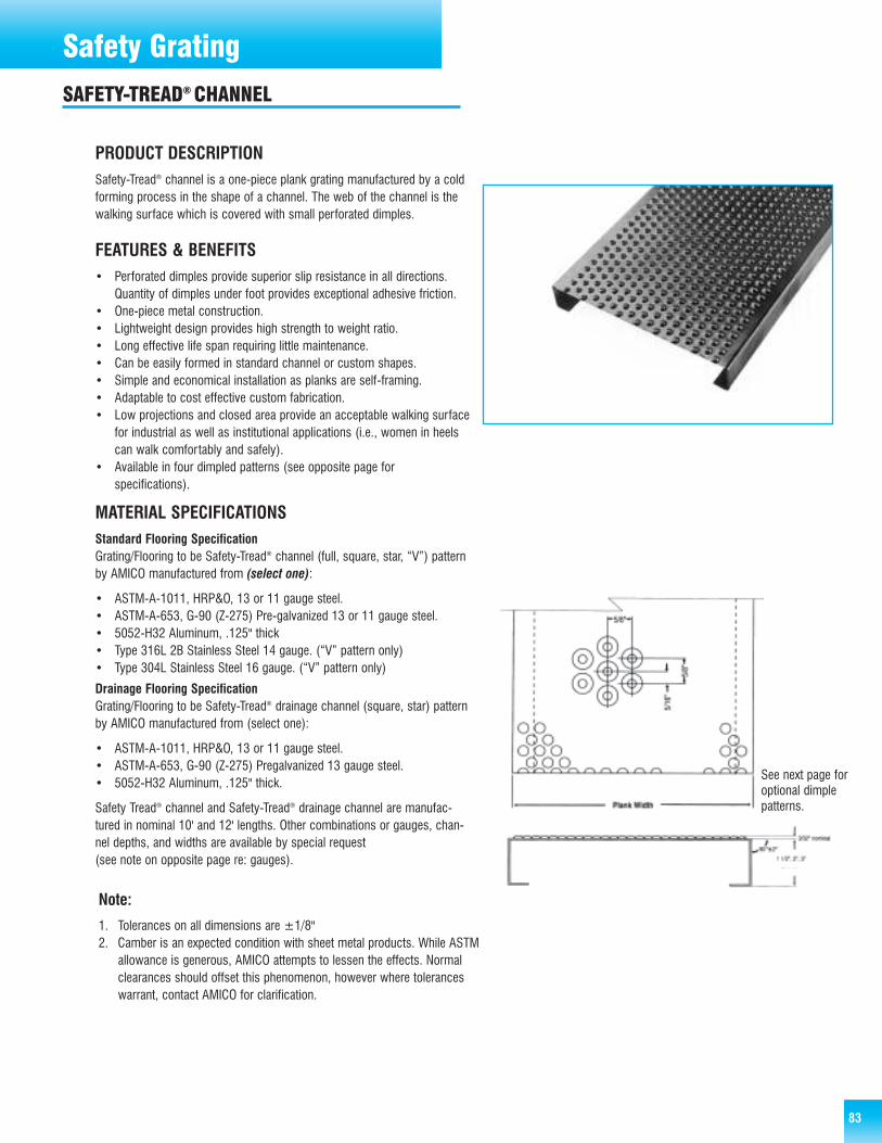
83
Safety GratingSAFETY-TREAD® CHANNEL
PRODUCT DESCRIPTIONSafety-Tread® channel is a one-piece plank grating manufactured by a coldforming process in the shape of a channel. The web of the channel is thewalking surface which is covered with small perforated dimples.
FEATURES & BENEFITS• Perforated dimples provide superior slip resistance in all directions.
Quantity of dimples under foot provides exceptional adhesive friction.• One-piece metal construction.• Lightweight design provides high strength to weight ratio.• Long effective life span requiring little maintenance.• Can be easily formed in standard channel or custom shapes.• Simple and economical installation as planks are self-framing.• Adaptable to cost effective custom fabrication.• Low projections and closed area provide an acceptable walking surface
for industrial as well as institutional applications (i.e., women in heelscan walk comfortably and safely).
• Available in four dimpled patterns (see opposite page forspecifications).
MATERIAL SPECIFICATIONSStandard Flooring SpecificationGrating/Flooring to be Safety-Tread® channel (full, square, star, “V”) patternby AMICO manufactured from (select one):
• ASTM-A-1011, HRP&O, 13 or 11 gauge steel.• ASTM-A-653, G-90 (Z-275) Pre-galvanized 13 or 11 gauge steel.• 5052-H32 Aluminum, .125" thick• Type 316L 2B Stainless Steel 14 gauge. (“V” pattern only)• Type 304L Stainless Steel 16 gauge. (“V” pattern only)
Drainage Flooring SpecificationGrating/Flooring to be Safety-Tread® drainage channel (square, star) patternby AMICO manufactured from (select one):
• ASTM-A-1011, HRP&O, 13 or 11 gauge steel.• ASTM-A-653, G-90 (Z-275) Pregalvanized 13 gauge steel.• 5052-H32 Aluminum, .125" thick.
Safety Tread® channel and Safety-Tread® drainage channel are manufac-tured in nominal 10' and 12' lengths. Other combinations or gauges, chan-nel depths, and widths are available by special request(see note on opposite page re: gauges).
See next page foroptional dimplepatterns.
Note:
1. Tolerances on all dimensions are ±1/8"2. Camber is an expected condition with sheet metal products. While ASTM
allowance is generous, AMICO attempts to lessen the effects. Normalclearances should offset this phenomenon, however where toleranceswarrant, contact AMICO for clarification.

84
Safety GratingSAFETY-TREAD® CHANNEL
LOAD & DEFLECTION TABLES
TECHNICALDETAILSOptional Dimpled Patterns
Explanation of Load TypeU = uniform load (lb/ft2)D = corresponding deflection (in) resulting from uniform loadC = concentrated load (lb)D = corresponding deflection (in) resulting from concentrated load
PRODUCT DET AILS Depth Catalog lx lN.4 L oad Type We ight Number Sx IN.3 T ype 24" 30" 36" 42" 48" 54" 60" 66" 72" 78" 84" 90" 96" 108" 120" 132" 144"
CLEAR SP AN FT
10 Inch Wide
1-1/2" TP5153 .272 U 1070 773 476 370 267 219 171 145 119 103 87 77 67
D 0 .05 0 .09 0 .12 0 .17 0 .21 0 .27 0 .33 0 .41 0 .48 0 .56 0 .65 0 .75 0 .85
4.24 Ib/f t . 267 C 625 610 594 519 445 400 356 326 297 275 254 238 223 D 0 .03 0 .06 0 .10 0 .14 0 .18 0 .22 0 .27 0 .33 0 .39 0 .45 0 .52 0 .60 0 .69
2" TP5203 .536 U 1500 1108 716 560 404 332 261 221 182 158 134 118 102 80 65 D 0 .04 0 .08 0 .10 0 .14 0 .17 0 .22 0 .27 0 .33 0 .39 0 .47 0 .54 0 .62 0 .70 0 .88 1 .08
4.84 Ib/f t . 404 C 625 625 625 625 625 582 539 494 449 418 387 359 332 300 274 D 0 .02 0 .03 0 .05 0 .09 0 .13 0 .18 0 .22 0 .27 0 .32 0 .38 0 .44 0 .50 0 .56 0 .72 0 .91
1-1/2" TP5151 .343 U 1343 971 599 468 338 278 218 185 152 132 113 100 87 D 0 .06 0 .10 0 .13 0 .19 0 .23 0 .30 0 .37 0 .45 0 .53 0 .63 0 .73 0 .85 0 .96
5.54 Ib/f t . 369 C 861 805 749 656 564 508 453 416 380 354 328 309 290 D 0 .04 0 .08 0 .11 0 .15 0 .19 0 .24 0 .29 0 .36 0 .43 0 .51 0 .59 0 .68 0 .77
2" TP5201 .689 U 1881 1366 851 676 501 410 320 271 223 194 164 145 126 99 80 D 0 .04 0 .07 0 .10 0 .15 0 .19 0 .25 0 .30 0 .37 0 .43 0 .51 0 .58 0 .67 0 .76 0 .96 1 .18
5.95 Ib/f t . 511 C 861 861 861 861 861 757 681 624 568 527 487 456 426 378 340 D 0 .02 0 .04 0 .06 0 .11 0 .16 0 .20 0 .24 0 .29 0 .35 0 .41 0 .48 0 .55 0 .62 0 .78 0 .97
Steel 13 GA
Steel 11 GA
PRODUCT DET AILS Depth Catalog lx lN.4 L oad Type We ight Number Sx IN.3 T ype 24" 30" 36" 42" 48" 54" 60" 66" 72" 78" 84" 90" 96" 108" 120" 132" 144"
CLEAR SP AN FT
12 Inch Wide
1-1/2" TP6153 .320 U 991 716 442 346 250 205 161 137 113 97 82 72 63 D 0 .05 0 .09 0 .12 0 .17 0 .21 0 .27 0 .33 0 .41 0 .48 0 .57 0 .65 0 .7 5 0 .85
4.83 lb/f t . 302 C 866 764 663 581 500 451 403 370 338 312 287 269 251 D 0 .04 0 .07 0 .10 0 .14 0 .18 0 .23 0 .28 0 .34 0 .40 0 .47 0 .55 0 .6 3 0 .72
2" TP6203 .630 U 1457 1053 649 508 367 301 236 200 165 143 122 108 94 75 60
D 0 .04 0 .08 0 .10 0 .14 0 .17 0 .23 0 .27 0 .33 0 .39 0 .47 0 .54 0 .6 3 0 .71 0 .90 1 .04
5.13 Ib/f t . 453 C 866 866 866 800 733 661 590 542 494 460 427 401 376 335 300 D 0 .02 0 .04 0 .07 0 .11 0 .14 0 .18 0 .22 0 .27 0 .32 0 .38 0 .44 0 .5 1 0 .58 0 .73 0 .90
1-1/2" TP6151 .406 U 1118 808 499 390 282 232 182 154 127 110 94 83 72 D 0 .06 0 .10 0 .12 0 .18 0 .22 0 .29 0 .35 0 .43 0 .50 0 .60 0 .69 0 .8 1 0 .93
6.33 Ib/f t . 376 C 1118 933 748 656 564 509 454 418 381 355 329 310 291 D 0 .05 0 .08 0 .11 0 .15 0 .19 0 .25 0 .30 0 .37 0 .44 0 .52 0 .60 0 .6 9 0 .79
2" TP6201 .792 U 1875 1201 835 614 471 373 303 251 211 180 156 136 120 96 78 D 0 .06 0 .09 0 .13 0 .18 0 .24 0 .31 0 .39 0 .46 0 .55 0 .64 0 .75 0 .86 0 .99 1 .27 1 .57
6.79 Ib/f t . 571 C 1362 1362 1253 1075 942 839 752 90 634 586 546 511 481 431 391 D 0 .03 0 .07 0 .11 0 .15 0 .20 0 .25 0 .31 0 .38 0 .45 0 .53 0 .62 0 .71 0 .82 1 .04 1 .297
Steel 13 GA
Steel 11 GA
Note: Due to the low profile of the walking surface, 11 guage material is recommended to help reduce strut deflection.
Note:• All uniform and concentrated loads include
a safety factor of 1.67.• Shaded areas, based on loads indicated,
may exceed deflections of L/120.

85
SAFETY-TREAD® FLOORING
Safety Grating
PRODUCT DESCRIPTIONSafety-Tread® is a metal flooring product which is covered with smallperforated dimples manufactured by a cold forming process.
OPTIONAL FEATURE:Safety-Tread® flooring is available in two drainage patterns which incor-porate embossed holes (staggered) between raised dimples.
FEATURES & BENEFITS• Perforated dimples provide superior slip resistance in all directions
and in all weather conditions. The quantity of dimples under footprovides exceptional adhesive friction.
• Long life span requiring little maintenance.• Can be easily formed into custom shapes.• Adaptable to wide range of applications.• Easily adaptable to cost effective, custom fabrication.• Low projections and closed area provide an acceptable walking
surface for industrial as well as institutional and commercialapplication (i.e., women in heels can walk comfortably and safely).
• Available in four dimpled patterns• Optional drainage flooring features smaller unembossed holes
(location and size variable with dimple pattern) providing drainage forliquid which may pool on walking surface in wet environments.
MATERIAL SPECIFICATIONSStandard Flooring SpecificationGrating shall be “Safety-Tread® flooring,” (full, square, star, “V”) patternby AMICO manufactured from (select one):
• ASTM-A-1011, HRP&O, 16, 13 or 11 gauge steel.• ASTM-A-653, G-90 (Z-275) Pre-galvanized 13 gauge steel.• 5052H32 Aluminum, .125" thick.• Type 316L, Stainless Steel 14 gauge (“V” pattern only)• Type 304L, Stainless Steel 16 gauge (“V” pattern only)
Drainage Flooring SpecificationFlooring shall be Safety-Tread® drainage flooring (square, star) pattern byAMICO manufactured from (select one):
• ASTM-A-1011, HRP&O, 11 gauge steel.• ASTM-A-653, G-90 (Z-275) Pre-galvanized 13 gauge square pattern
or 11 gauge star pattern.• 5052H32 Aluminum, .125" thick.
SQUARE DRAINAGE STAR DRAINAGE

86
Safety GratingSAFETY-TREAD® FLOORING
Safety-Tread® FlooringGauge Material Wt/Sq Ft Catalog
Number11 GA HRP&O 5.0 LB/SQ FT 2T3101B13 GA HRP&O 3.8 LB/SQ FT 2T3103B16 GA HRP&O 2.5 LB/SQ FT 2T3106B13 GA GALV. 1.7 LB/SQ FT 2T3103G.125" ALU. 1.6 LB/SQ FT 2T3108A14 GA 316 L 3.28 LB/SQ FT 2T3104S16 GA 304 L 2.4 LB/SQ FT 2T3106S
Drainage Flooring16 GA HRP&O 2.3 LB/SQ FT 2TD310613 GA HRP&O 3.5 LB/SQ FT 2TD3103B11 GA HRP&O 4.7 LB/SQ FT 2TD3101B.125" ALU. 1.6 LB/SQ FT 2TD3108A
TECHNICALDETAILS

8787
Safety GratingSAFETY-TREAD® LADDER RUNGS
PRODUCT DESCRIPTIONSafety-Tread® ladder rungs are small channel shaped sections; the web ofthe channel being the walking surface which is covered with small perforat-ed dimples, produced by a cold forming process.
FEATURES & BENEFITS• Perforated dimples provide superior slip resistance in all directions and
in all weather conditions. The quantity of dimples under foot providesexceptional adhesive friction.
• Cross sectional design provides significant load carrying capacity onspans up to 24".
• Three widths of rung to choose from.• Leading row of dimples projected on the edge of the rung provides slip
resistance to the foot approaching at an angle to the walking surface.• Long life span requiring little maintenance.• Adaptable to a wide range of applications.• Easily adaptable to cost effective, custom fabrication.• Ideal for retrofit applications as rungs fit over slippery pipes, bars, etc.
on existing ladders.
MATERIAL SPECIFICATIONSLadder rungs shall be “Safety-Tread® ladder rungs,” manufactured from(see ‘Selections’ below) by AMICO.
SELECTIONS• ASTM-A-1011, 13 or 11 gauge, HRP&O steel.• ASTM-A-653, 13 gauge, G-90 (Z-275) Pre-galvanized steel.• 5052H32 .125" thick, Aluminum.• Type 316L, 14 gauge Stainless Steel.
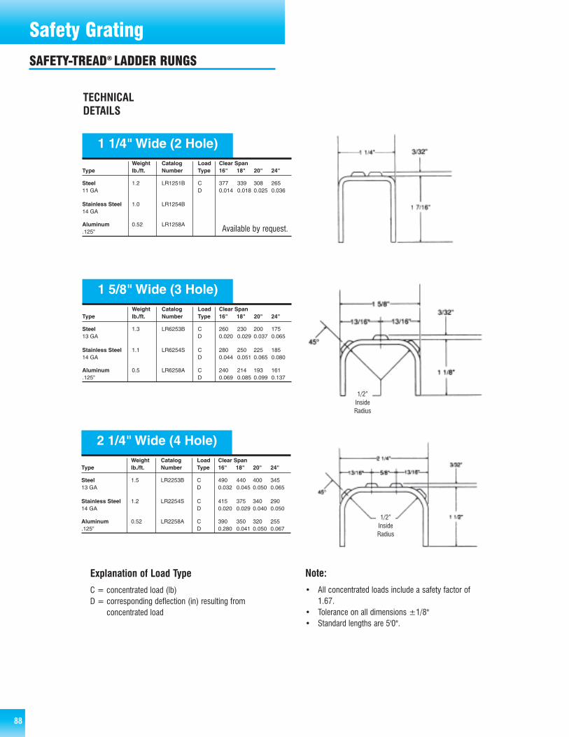
88 88
Safety GratingSAFETY-TREAD® LADDER RUNGS
TECHNICALDETAILS
Weight Catalog Load Clear SpanType lb./ft. Number Type 16" 18" 20" 24"
Steel 1.2 LR1251B C 377 339 308 26511 GA D 0.014 0.018 0.025 0.036
Stainless Steel 1.0 LR1254B14 GA
Aluminum 0.52 LR1258A.125"
1 1/4" Wide (2 Hole)
Weight Catalog Load Clear SpanType lb./ft. Number Type 16" 18" 20" 24"
Steel 1.3 LR6253B C 260 230 200 175 13 GA D 0.020 0.029 0.037 0.065
Stainless Steel 1.1 LR6254S C 280 250 225 185 14 GA D 0.044 0.051 0.065 0.080
Aluminum 0.5 LR6258A C 240 214 193 161 .125" D 0.069 0.085 0.099 0.137
1 5/8" Wide (3 Hole)
Weight Catalog Load Clear SpanType lb./ft. Number Type 16" 18" 20" 24"
Steel 1.5 LR2253B C 490 440 400 34513 GA D 0.032 0.045 0.050 0.065
Stainless Steel 1.2 LR2254S C 415 375 340 29014 GA D 0.020 0.029 0.040 0.050
Aluminum 0.52 LR2258A C 390 350 320 255.125" D 0.280 0.041 0.050 0.067
2 1/4" Wide (4 Hole)
Explanation of Load Type
C = concentrated load (lb)D = corresponding deflection (in) resulting from
concentrated load
Note:
• All concentrated loads include a safety factor of1.67.
• Tolerance on all dimensions ±1/8"• Standard lengths are 5'0".
Available by request.
1/2”InsideRadius
1/2”InsideRadius
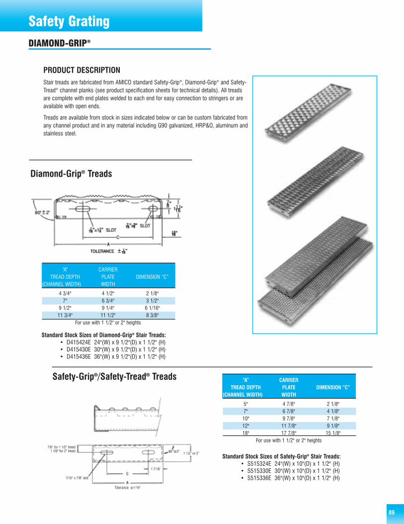
89
Safety GratingDIAMOND-GRIP®
Diamond-Grip® Treads
Safety-Grip®/Safety-Tread® Treads
“A” CARRIERTREAD DEPTH PLATE DIMENSION “C”
(CHANNEL WIDTH) WIDTH
4 3/4" 4 1/2" 2 1/8"7" 6 3/4" 3 1/2"
9 1/2" 9 1/4" 6 1/16"11 3/4" 11 1/2" 8 3/8"
For use with 1 1/2" or 2" heights
Standard Stock Sizes of Diamond-Grip® Stair Treads:• D415424E 24"(W) x 9 1/2"(D) x 1 1/2" (H)• D415430E 30"(W) x 9 1/2"(D) x 1 1/2" (H)• D415436E 36"(W) x 9 1/2"(D) x 1 1/2" (H)
“A” CARRIERTREAD DEPTH PLATE DIMENSION “C”
(CHANNEL WIDTH) WIDTH
5" 4 7/8" 2 1/8"7" 6 7/8" 4 1/8"10" 9 7/8" 7 1/8"12" 11 7/8" 9 1/8"18" 17 7/8" 15 1/8"
For use with 1 1/2" or 2" heights
Standard Stock Sizes of Safety-Grip® Stair Treads:• S515324E 24"(W) x 10"(D) x 1 1/2" (H)• S515330E 30"(W) x 10"(D) x 1 1/2" (H)• S515336E 36"(W) x 10"(D) x 1 1/2" (H)
PRODUCT DESCRIPTIONStair treads are fabricated from AMICO standard Safety-Grip®, Diamond-Grip® and Safety-Tread® channel planks (see product specification sheets for technical details). All treadsare complete with end plates welded to each end for easy connection to stringers or areavailable with open ends.
Treads are available from stock in sizes indicated below or can be custom fabricated fromany channel product and in any material including G90 galvanized, HRP&O, aluminum andstainless steel.
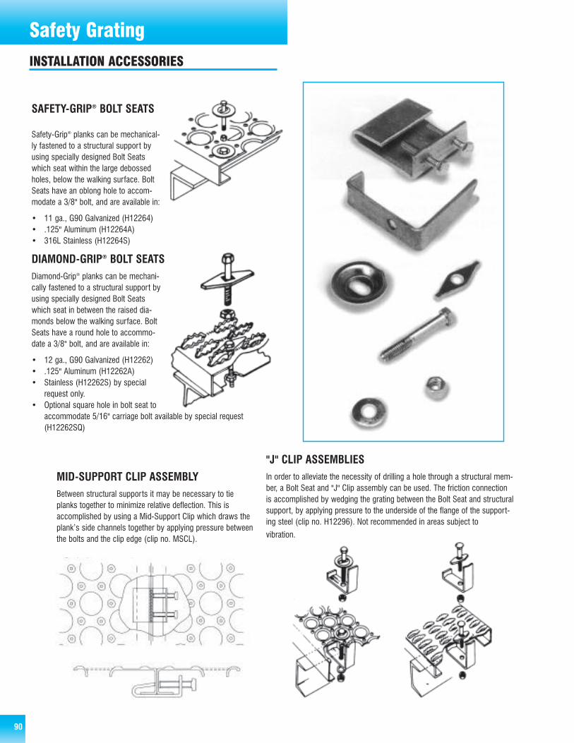
90
Safety Grating
SAFETY-GRIP® BOLT SEATS
Safety-Grip® planks can be mechanical-ly fastened to a structural support byusing specially designed Bolt Seatswhich seat within the large debossedholes, below the walking surface. BoltSeats have an oblong hole to accom-modate a 3/8" bolt, and are available in:
• 11 ga., G90 Galvanized (H12264)• .125" Aluminum (H12264A)• 316L Stainless (H12264S)
DIAMOND-GRIP® BOLT SEATSDiamond-Grip® planks can be mechani-cally fastened to a structural support byusing specially designed Bolt Seatswhich seat in between the raised dia-monds below the walking surface. BoltSeats have a round hole to accommo-date a 3/8" bolt, and are available in:
• 12 ga., G90 Galvanized (H12262)• .125" Aluminum (H12262A)• Stainless (H12262S) by special
request only.• Optional square hole in bolt seat to
accommodate 5/16" carriage bolt available by special request(H12262SQ)
"J" CLIP ASSEMBLIESIn order to alleviate the necessity of drilling a hole through a structural mem-ber, a Bolt Seat and "J" Clip assembly can be used. The friction connectionis accomplished by wedging the grating between the Bolt Seat and structuralsupport, by applying pressure to the underside of the flange of the support-ing steel (clip no. H12296). Not recommended in areas subject to
vibration.
MID-SUPPORT CLIP ASSEMBLYBetween structural supports it may be necessary to tieplanks together to minimize relative deflection. This isaccomplished by using a Mid-Support Clip which draws theplank’s side channels together by applying pressure betweenthe bolts and the clip edge (clip no. MSCL).
INSTALLATION ACCESSORIES
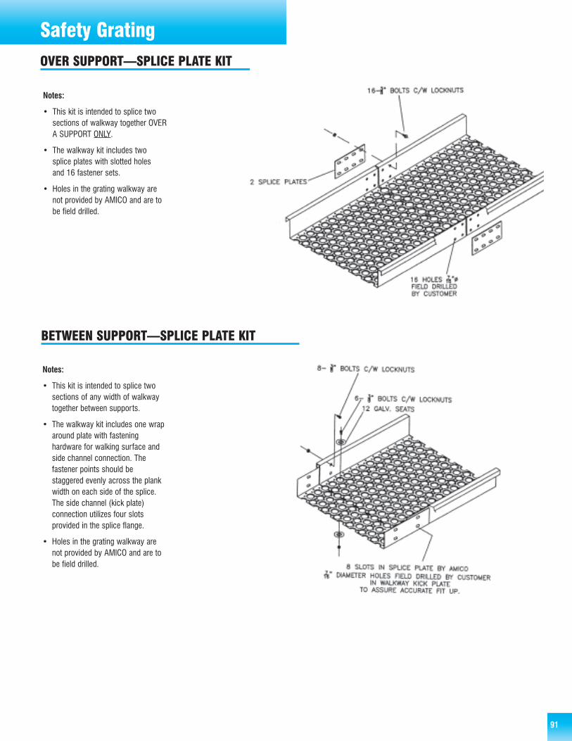
OVER SUPPORT—SPLICE PLATE KIT
91
Safety Grating
Notes:
• This kit is intended to splice twosections of walkway together OVERA SUPPORT ONLY.
• The walkway kit includes twosplice plates with slotted holesand 16 fastener sets.
• Holes in the grating walkway arenot provided by AMICO and are tobe field drilled.
Notes:
• This kit is intended to splice twosections of any width of walkwaytogether between supports.
• The walkway kit includes one wraparound plate with fasteninghardware for walking surface andside channel connection. Thefastener points should bestaggered evenly across the plankwidth on each side of the splice.The side channel (kick plate)connection utilizes four slotsprovided in the splice flange.
• Holes in the grating walkway arenot provided by AMICO and are tobe field drilled.
BETWEEN SUPPORT—SPLICE PLATE KIT
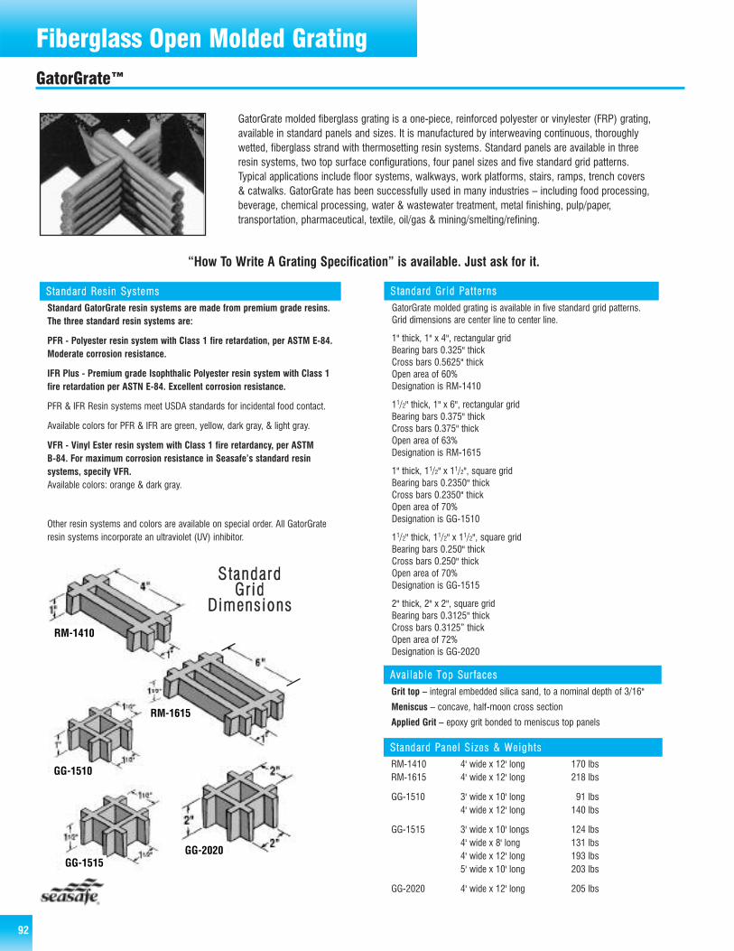
92
Steel Bar GratingFiberglass Open Molded GratingGatorGrate™
GatorGrate molded fiberglass grating is a one-piece, reinforced polyester or vinylester (FRP) grating,available in standard panels and sizes. It is manufactured by interweaving continuous, thoroughlywetted, fiberglass strand with thermosetting resin systems. Standard panels are available in threeresin systems, two top surface configurations, four panel sizes and five standard grid patterns.Typical applications include floor systems, walkways, work platforms, stairs, ramps, trench covers& catwalks. GatorGrate has been successfully used in many industries – including food processing,beverage, chemical processing, water & wastewater treatment, metal finishing, pulp/paper,transportation, pharmaceutical, textile, oil/gas & mining/smelting/refining.
“How To Write A Grating Specification” is available. Just ask for it.
SSttaa nnddaarrdd RReessiinn SSyyssttee mmss
Standard GatorGrate resin systems are made from premium grade resins.The three standard resin systems are:
PFR - Polyester resin system with Class 1 fire retardation, per ASTM E-84.Moderate corrosion resistance.
IFR Plus - Premium grade Isophthalic Polyester resin system with Class 1fire retardation per ASTN E-84. Excellent corrosion resistance.
PFR & IFR Resin systems meet USDA standards for incidental food contact.
Available colors for PFR & IFR are green, yellow, dark gray, & light gray.
VFR - Vinyl Ester resin system with Class 1 fire retardancy, per ASTM B-84. For maximum corrosion resistance in Seasafe’s standard resin systems, specify VFR.Available colors: orange & dark gray.
Other resin systems and colors are available on special order. All GatorGrateresin systems incorporate an ultraviolet (UV) inhibitor.
SSttaannddaa rrdd GGrr iidd PPaa tttteerrnnss
GatorGrate molded grating is available in five standard grid patterns.Grid dimensions are center line to center line.
1" thick, 1" x 4", rectangular gridBearing bars 0.325" thickCross bars 0.5625" thickOpen area of 60%Designation is RM-1410
11/2" thick, 1" x 6", rectangular gridBearing bars 0.375" thickCross bars 0.375" thickOpen area of 63%Designation is RM-1615
1" thick, 11/2" x 11/2", square gridBearing bars 0.2350" thickCross bars 0.2350" thickOpen area of 70%Designation is GG-1510
11/2" thick, 11/2" x 11/2", square gridBearing bars 0.250" thickCross bars 0.250" thickOpen area of 70%Designation is GG-1515
2" thick, 2" x 2", square gridBearing bars 0.3125" thickCross bars 0.3125” thickOpen area of 72%Designation is GG-2020
AAvvaaii llaabb llee TToopp SSuurr ffaacceess
Grit top – integral embedded silica sand, to a nominal depth of 3/16"
Meniscus – concave, half-moon cross section
Applied Grit – epoxy grit bonded to meniscus top panels
SSttaa nnddaarrdd PPaa nneell SS iizzeess && WWeeiigghhttss
RM-1410 4' wide x 12' long 170 lbsRM-1615 4' wide x 12' long 218 lbs
GG-1510 3' wide x 10' long 91 lbs4' wide x 12' long 140 lbs
GG-1515 3' wide x 10' longs 124 lbs4' wide x 8' long 131 lbs4' wide x 12' long 193 lbs5' wide x 10' long 203 lbs
GG-2020 4' wide x 12' long 205 lbs
RM-1410
RM-1615
GG-1510
GG-2020GG-1515
SSttaannddaarrddGGrriidd
DDiimmeennssiioonnss
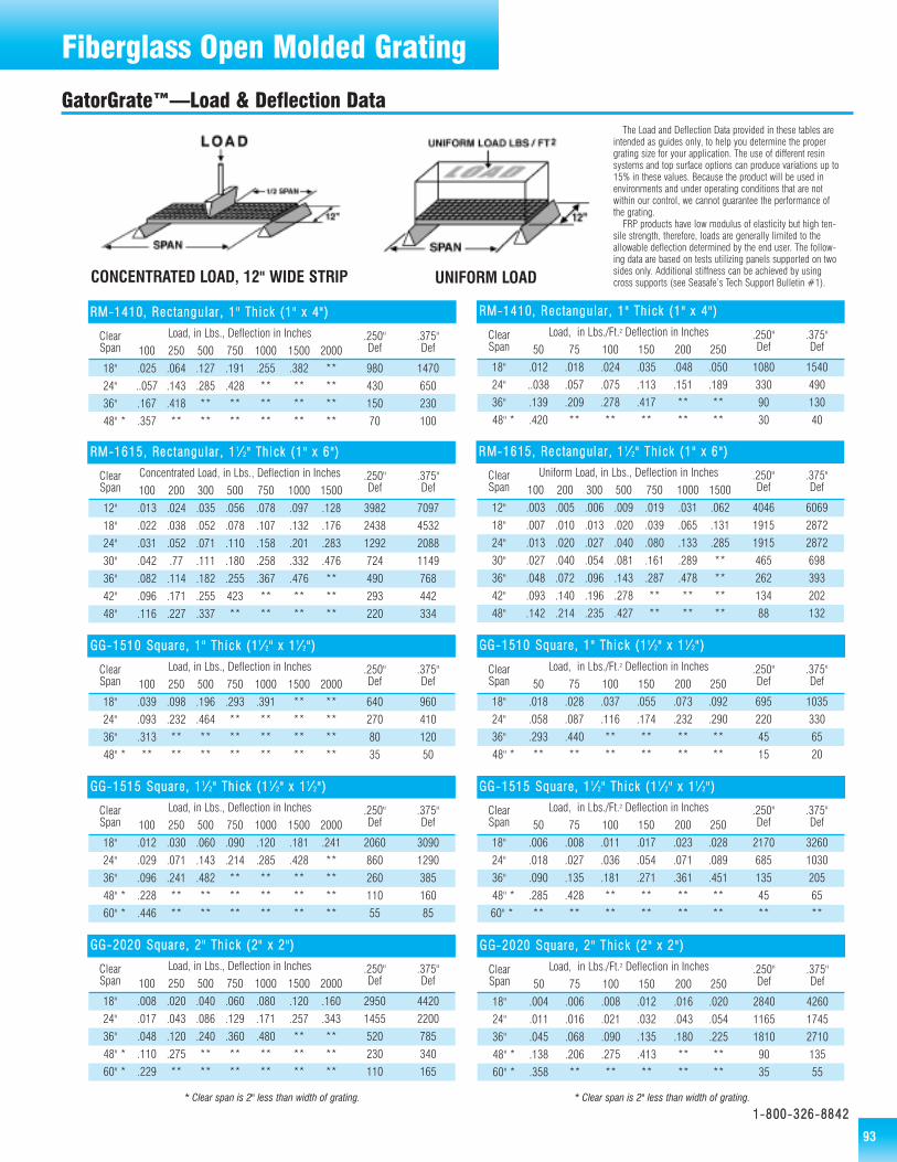
Fiberglass Open Molded GratingGatorGrate™—Load & Deflection Data
GGGG--22002200 SSqquuaarree,, 22"" TThhiicc kk ((22"" xx 22"" ))
Clear Load, in Lbs./Ft.2 Deflection in Inches .250" .375"Span 50 75 100 150 200 250 Def Def
18" .004 .006 .008 .012 .016 .020 2840 4260
24" .011 .016 .021 .032 .043 .054 1165 1745
36" .045 .068 .090 .135 .180 .225 1810 2710
48" * .138 .206 .275 .413 ** ** 90 135
60" * .358 ** ** ** ** ** 35 55
GGGG--11551155 SSqquuaarree,, 11 11⁄⁄ 22"" TThhiicckk ((11 11⁄⁄ 22"" xx 1111⁄⁄ 22"" ))
Clear Load, in Lbs./Ft.2 Deflection in Inches .250" .375"Span 50 75 100 150 200 250 Def Def
18" .006 .008 .011 .017 .023 .028 2170 3260
24" .018 .027 .036 .054 .071 .089 685 1030
36" .090 .135 .181 .271 .361 .451 135 205
48" * .285 .428 ** ** ** ** 45 65
60" * ** ** ** ** ** ** ** **
GGGG--11551100 SSqquuaarree,, 11"" TThhiicc kk ((1111⁄⁄ 22"" xx 11 11⁄⁄ 22"" ))
Clear Load, in Lbs./Ft.2 Deflection in Inches .250" .375"Span 50 75 100 150 200 250 Def Def
18" .018 .028 .037 .055 .073 .092 695 1035
24" .058 .087 .116 .174 .232 .290 220 330
36" .293 .440 ** ** ** ** 45 65
48" * ** ** ** ** ** ** 15 20
RRMM--11441100,, RReeccttaanngguullaarr ,, 11"" TThhiicckk ((11"" xx 44"" ))
Clear Load, in Lbs./Ft.2 Deflection in Inches .250" .375"Span 50 75 100 150 200 250 Def Def
18" .012 .018 .024 .035 .048 .050 1080 1540
24" ..038 .057 .075 .113 .151 .189 330 490
36" .139 .209 .278 .417 ** ** 90 130
48" * .420 ** ** ** ** ** 30 40
CONCENTRATED LOAD, 12" WIDE STRIP UNIFORM LOAD
* Clear span is 2" less than width of grating. * Clear span is 2" less than width of grating.
RRMM--11661155,, RReecctt aanngguullaarr ,, 11 11⁄⁄ 22"" TThhiicckk ((11"" xx 66""))
Clear Concentrated Load, in Lbs., Deflection in Inches .250" .375"Span 100 200 300 500 750 1000 1500 Def Def
12" .013 .024 .035 .056 .078 .097 .128 3982 7097
18" .022 .038 .052 .078 .107 .132 .176 2438 4532
24" .031 .052 .071 .110 .158 .201 .283 1292 2088
30" .042 .77 .111 .180 .258 .332 .476 724 1149
36" .082 .114 .182 .255 .367 .476 ** 490 768
42" .096 .171 .255 423 ** ** ** 293 442
48" .116 .227 .337 ** ** ** ** 220 334
GGGG--11551100 SSqquuaarree,, 11"" TThhiicc kk ((1111⁄⁄ 22"" xx 11 11⁄⁄ 22"" ))
Clear Load, in Lbs., Deflection in Inches .250" .375"Span 100 250 500 750 1000 1500 2000 Def Def
18" .039 .098 .196 .293 .391 ** ** 640 960
24" .093 .232 .464 ** ** ** ** 270 410
36" .313 ** ** ** ** ** ** 80 120
48" * ** ** ** ** ** ** ** 35 50
RRMM--11441100,, RReeccttaanngguullaarr ,, 11"" TThhiicckk ((11"" xx 44"" ))
Clear Load, in Lbs., Deflection in Inches .250" .375"Span 100 250 500 750 1000 1500 2000 Def Def
18" .025 .064 .127 .191 .255 .382 ** 980 1470
24" ..057 .143 .285 .428 ** ** ** 430 650
36" .167 .418 ** ** ** ** ** 150 230
48" * .357 ** ** ** ** ** ** 70 100
GGGG--11551155 SSqquuaarree,, 11 11⁄⁄ 22"" TThhiicckk ((11 11⁄⁄ 22"" xx 1111⁄⁄ 22"" ))
Clear Load, in Lbs., Deflection in Inches .250" .375"Span 100 250 500 750 1000 1500 2000 Def Def
18" .012 .030 .060 .090 .120 .181 .241 2060 3090
24" .029 .071 .143 .214 .285 .428 ** 860 1290
36" .096 .241 .482 ** ** ** ** 260 385
48" * .228 ** ** ** ** ** ** 110 160
60" * .446 ** ** ** ** ** ** 55 85
GGGG--22002200 SSqquuaarree,, 22"" TThhiicc kk ((22"" xx 22""))
Clear Load, in Lbs., Deflection in Inches .250" .375"Span 100 250 500 750 1000 1500 2000 Def Def
18" .008 .020 .040 .060 .080 .120 .160 2950 4420
24" .017 .043 .086 .129 .171 .257 .343 1455 2200
36" .048 .120 .240 .360 .480 ** ** 520 785
48" * .110 .275 ** ** ** ** ** 230 340
60" * .229 ** ** ** ** ** ** 110 165
RRMM--11661155,, RRee ccttaanngguull aarr ,, 11 11⁄⁄ 22"" TThhiicckk ((11"" xx 66"" ))
Clear Uniform Load, in Lbs., Deflection in Inches .250" .375"Span 100 200 300 500 750 1000 1500 Def Def
12" .003 .005 .006 .009 .019 .031 .062 4046 6069
18" .007 .010 .013 .020 .039 .065 .131 1915 2872
24" .013 .020 .027 .040 .080 .133 .285 1915 2872
30" .027 .040 .054 .081 .161 .289 ** 465 698
36" .048 .072 .096 .143 .287 .478 ** 262 393
42" .093 .140 .196 .278 ** ** ** 134 202
48" .142 .214 .235 .427 ** ** ** 88 132
The Load and Deflection Data provided in these tables areintended as guides only, to help you determine the propergrating size for your application. The use of different resinsystems and top surface options can produce variations up to15% in these values. Because the product will be used inenvironments and under operating conditions that are notwithin our control, we cannot guarantee the performance ofthe grating.
FRP products have low modulus of elasticity but high ten-sile strength, therefore, loads are generally limited to theallowable deflection determined by the end user. The follow-ing data are based on tests utilizing panels supported on twosides only. Additional stiffness can be achieved by usingcross supports (see Seasafe’s Tech Support Bulletin #1).
11--880000--332266--88884422
93
Fiberglass Open Molded Grating
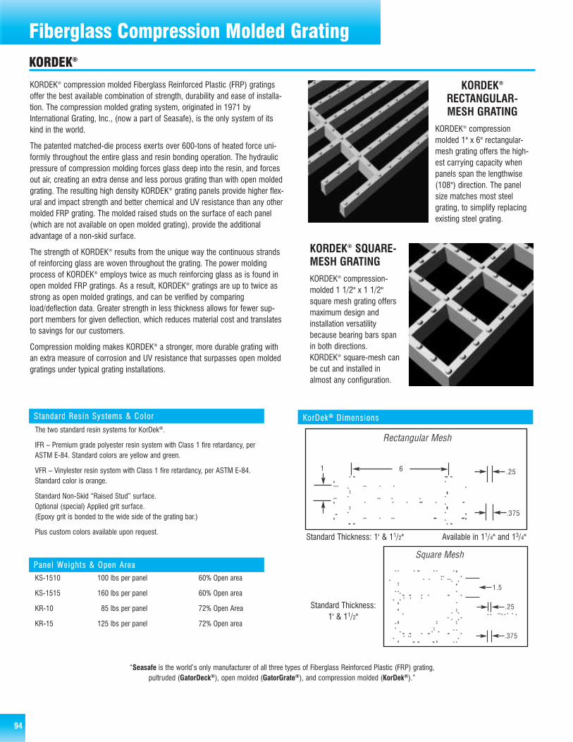
94
Steel Bar GratingFiberglass Compression Molded GratingKORDEK®
KORDEK® SQUARE-MESH GRATINGKORDEK® compression-molded 1 1/2" x 1 1/2"square mesh grating offersmaximum design and installation versatilitybecause bearing bars spanin both directions.KORDEK® square-mesh canbe cut and installed inalmost any configuration.
KORDEK®
RECTANGULAR-MESH GRATING
KORDEK® compressionmolded 1" x 6" rectangular-mesh grating offers the high-est carrying capacity whenpanels span the lengthwise(108") direction. The panelsize matches most steelgrating, to simplify replacingexisting steel grating.
KORDEK® compression molded Fiberglass Reinforced Plastic (FRP) gratingsoffer the best available combination of strength, durability and ease of installa-tion. The compression molded grating system, originated in 1971 byInternational Grating, Inc., (now a part of Seasafe), is the only system of itskind in the world.
The patented matched-die process exerts over 600-tons of heated force uni-formly throughout the entire glass and resin bonding operation. The hydraulicpressure of compression molding forces glass deep into the resin, and forcesout air, creating an extra dense and less porous grating than with open moldedgrating. The resulting high density KORDEK® grating panels provide higher flex-ural and impact strength and better chemical and UV resistance than any othermolded FRP grating. The molded raised studs on the surface of each panel(which are not available on open molded grating), provide the additionaladvantage of a non-skid surface.
The strength of KORDEK® results from the unique way the continuous strandsof reinforcing glass are woven throughout the grating. The power moldingprocess of KORDEK® employs twice as much reinforcing glass as is found inopen molded FRP gratings. As a result, KORDEK® gratings are up to twice asstrong as open molded gratings, and can be verified by comparingload/deflection data. Greater strength in less thickness allows for fewer sup-port members for given deflection, which reduces material cost and translatesto savings for our customers.
Compression molding makes KORDEK® a stronger, more durable grating withan extra measure of corrosion and UV resistance that surpasses open moldedgratings under typical grating installations.
SSttaannddaa rrdd RReess iinn SSyy sstteemmss && CCoolloorr
The two standard resin systems for KorDek®.
IFR – Premium grade polyester resin system with Class 1 fire retardancy, perASTM E-84. Standard colors are yellow and green.
VFR – Vinylester resin system with Class 1 fire retardancy, per ASTM E-84.Standard color is orange.
Standard Non-Skid “Raised Stud” surface.Optional (special) Applied grit surface.(Epoxy grit is bonded to the wide side of the grating bar.)
Plus custom colors available upon request.
PPaanneell WWeeiigghhtt ss && OOppeenn AArreeaa
KS-1510 100 lbs per panel 60% Open area
KS-1515 160 lbs per panel 60% Open area
KR-10 85 lbs per panel 72% Open Area
KR-15 125 lbs per panel 72% Open area
KKoorrDDeekk ®® DDiimmeennssiioonnss
Standard Thickness: 1’ & 11/2” Available in 11/4” and 13/4”
Standard Thickness:
1’ & 11/2”
Standard Thickness: 1’ & 11/2” Available in 11/4” and 13/4”
Standard Thickness:
1’ & 11/2”
“Seasafe is the world’s only manufacturer of all three types of Fiberglass Reinforced Plastic (FRP) grating,pultruded (GatorDeck®), open molded (GatorGrate®), and compression molded (KorDek®).”
Standard Thickness: 1' & 11/2" Available in 11/4" and 13/4"
Standard Thickness: 1' & 11/2"

KORDEK® UNIFORM LOADKKSS--11551100,, 11"" TThhiicckk,, 1111//22"" xx 1111//22"" SSqquuaarree MMeesshh
Clear Load, in Lbs., Deflection in Inches .250" .375"Span 50 100 200 300 500 1000 2000 Def Def
18" 0.01 0.03 0.05 0.08 0.13 0.26 ** 962 1442
24" 0.04 0.08 0.16 0.23 0.39 ** ** 321 481
36" 0.19 0.36 ** ** ** ** ** 69 104
KKSS--11550011,, 11"" TThhiicckk ,, 1111//22"" xx 1111//22"" SSqquuaarree MMeesshh
Clear Load, in Lbs., Deflection in Inches .250" .375"Span 50 100 200 300 500 1000 2000 Def Def
18" 0.01 0.03 0.06 0.08 0.14 0.28 ** 893 1339
24" 0.03 0.06 0.13 0.19 0.31 ** ** 403 605
36" 0.10 0.19 0.37 ** ** ** ** 135 203
KKSS--11551155,, 1111// 22"" TThhiicckk ,, 1111//22"" xx 1111// 22"" SSqquuaa rree MMeesshh
Clear Load, in Lbs., Deflection in Inches .250" .375"Span 50 100 200 300 500 1000 2000 Def Def
18" <0.01 0.01 0.02 0.02 0.04 0.08 0.15 3333 5000
24" 0.01 0.02 0.04 0.07 0.11 0.22 0.44 1136 1705
36" 0.05 0.10 0.20 0.30 0.50 ** ** 250 375
48" 0.16 0.31 ** ** ** ** ** 81 121
54" 0.25 0.48 ** ** ** ** ** 52 78
60" 0.37 ** ** ** ** ** ** 34 51
KKRR--1122,, 1111//44"" TThhiicc kk,, 11"" xx 66"" RReeccttaa nngguullaarr MMeesshh (Special)
Clear Load, in Lbs., Deflection in Inches .250" .375"Span 50 100 200 300 500 1000 2000 Def Def
18" 0.01 0.01 0.02 0.03 0.05 0.10 0.19 2632 3947
24" 0.02 0.03 0.06 0.09 0.14 0.29 ** 862 1293
36" 0.07 0.14 0.28 0.41 ** ** ** 183 274
48" 0.22 0.43 ** ** ** ** ** 58 87
54" 0.31 ** ** ** ** ** ** 40 60
KKRR--1155,, 1111//22"" TThhiicc kk,, 11"" xx 66"" RReeccttaa nngguullaarr MMeesshh
Clear Load, in Lbs., Deflection in Inches .250" .375"Span 50 100 200 300 500 1000 2000 Def Def
18" <0.01 0.01 0.02 0.02 0.04 0.07 0.15 3333 5000
24" 0.01 0.02 0.04 0.06 0.10 0.19 0.39 1282 1923
36" 0.04 0.08 0.17 0.25 0.41 ** ** 305 457
48" 0.13 0.25 0.49 ** ** ** ** 102 153
54" 0.19 0.37 ** ** ** ** ** 68 101
60" 0.29 ** ** ** ** ** ** 43 65
KKRR--1177,, 1133//44"" TThhiicc kk,, 11"" xx 66"" RReeccttaa nngguullaarr MMeesshh (Special)
Clear Load, in Lbs., Deflection in Inches .250" .375"Span 50 100 200 300 500 1000 2000 Def Def
18" <0.01<0.01 0.01 0.01 0.02 0.05 0.09 5556 8333
24" 0.01 0.01 0.03 0.04 0.06 0.13 0.25 2000 3000
36" 0.03 0.06 0.11 0.17 0.28 ** ** 446 670
48" 0.09 0.16 0.32 0.47 ** ** ** 160 239
54" 0.14 0.26 0.50 ** ** ** ** 100 150
60" 0.21 0.39 ** ** ** ** ** 64 96
66" 0.30 ** ** ** ** ** ** 42 63
72" 0.42 ** ** ** ** ** ** 30 45
KKRR--1155,, 1111// 22"" TThhiicckk ,, 11"" xx 66"" RRee ccttaanngguull aarr MMeesshh
Clear Load, in Lbs., Deflection in Inches .250" .375"Span 50 100 200 300 500 1000 2000 Def Def
18" <0.01 0.01 0.02 0.02 0.04 0.08 0.16 3125 4688
24" 0.01 0.02 0.03 0.05 0.08 0.16 0.31 1613 2419
36" 0.02 0.05 0.09 0.13 0.22 0.43 ** 581 872
48" 0.05 0.10 0.20 0.29 0.48 ** ** 260 391
54" 0.07 0.13 0.26 0.39 ** ** ** 192 288
60" 0.09 0.18 0.35 0.50 ** ** ** 150 225
66" 0.18 0.34 ** ** ** ** ** 76 114
KKRR--1122,, 1111//44"" TThhiicckk ,, 11"" xx 66"" RReecctt aanngguullaa rr MMeesshh (Special)
Clear Load, in Lbs., Deflection in Inches .250" .375"Span 50 100 200 300 500 1000 2000 Def Def
18" 0.01 0.01 0.02 0.03 0.05 0.10 0.21 2381 3571
24" 0.01 0.02 0.05 0.07 0.12 0.23 0.046 1087 1630
36" 0.04 0.08 0.15 0.22 0.36 ** ** 347 521
48" 0.09 0.17 0.33 0.50 ** ** ** 150 225
54" 0.11 0.21 0.42 ** ** ** ** 119 179
KKSS--11551155,, 1111//22"" TThhiicckk,, 1111//22"" xx 1111//22"" SSqquuaarree MMeesshh
Clear Load, in Lbs., Deflection in Inches .250" .375"Span 50 100 200 300 500 1000 2000 Def Def
18" <0.01 0.01 0.02 0.02 0.04 0.08 0.16 3125 4688
24" 0.01 0.02 0.04 0.05 0.09 0.18 0.35 1429 2143
36" 0.03 0.06 0.11 0.16 0.27 ** ** 463 694
48" 0.06 0.12 0.24 0.36 ** ** ** 208 313
54" 0.09 0.17 0.33 0.49 ** ** ** 153 230
60" 0.12 0.23 0.44 ** ** ** ** 144 170
KKRR--1177,, 1133//44"" TThhiicc kk,, 11"" xx 66"" RReeccttaa nngguullaarr MMeesshh (Special)
Clear Load, in Lbs., Deflection in Inches .250" .375"Span 50 100 200 300 500 1000 2000 Def Def
18" <0.01<0.01 0.01 0.02 0.03 0.05 0.10 5000 7500
24" 0.01 0.01 0.02 0.03 0.05 0.10 0.20 2500 3750
36" 0.02 0.03 0.06 0.09 0.15 0.29 ** 862 1293
48" 0.03 0.07 0.13 0.19 0.31 ** ** 403 605
54" 0.05 0.09 0.18 0.27 0.44 ** ** 284 426
60" 0.07 0.12 0.24 0.36 ** ** ** 208 313
66" 0.09 0.16 0.32 0.48 ** ** ** 156 234
72" 0.11 0.21 0.41 ** ** ** ** 122 183
KORDEK® CONCENTRATED LOAD, 12" WIDE STRIP
KKRR--1100,, 11"" TThhiicckk ,, 11"" xx 66"" RReecc ttaanngguull aarr MMeesshh
Clear Load, in Lbs., Deflection in Inches .250" .375"Span 50 100 200 300 500 1000 2000 Def Def
18" 0.01 0.01 0.03 0.04 0.06 0.13 0.25 2000 3000
24" 0.02 0.04 0.08 0.11 0.19 0.37 ** 676 1014
36" 0.09 0.18 0.35 ** ** ** ** 143 214
48 0.28 ** ** ** ** ** ** 45 67
KKRR--1100,, 11"" TThhiicckk,, 11"" xx 66"" RReecctt aanngguullaarr MMeess hh
Clear Load, in Lbs., Deflection in Inches .250" .375"Span 50 100 200 300 500 1000 2000 Def Def
18" 0.01 0.01 0.03 0.04 0.07 0.13 0.27 1852 2778
24" 0.02 0.03 0.06 0.09 0.15 0.30 ** 833 1250
36" 0.05 0.09 0.19 0.28 0.46 ** ** 272 408
48 0.11 0.22 0.43 ** ** ** ** 116 174
The Load and Deflection Data provided in these tables are intended for guidance only, to help you determine the proper grating for your application. The use of different resin systems and surfaces canproduce variations upt to 15% in these values. Because the product will be used in enviornments and under operating conditions that are not within our control, we cannot guarantee the performance ofthe grating. FRP products have low modulus of elasticity but high tensile strength, therefore loads are generally liminted to the allowable deflection determined by the end user. The following data arebased on tests utilizing panels supported on two sides only. Additional stiffness can be achieved by using cross supports. 95
Fiberglass Compression Molded Grating

96
Steel Bar GratingFiberglass GatorPlate & Covered Molded GratingGatorPlateTM floor plate is perfect for fixing slippery spots or in largeslippery areas. The anti-slip surface helps reduce slips & falls evenwhen hazardous liquids are present.
Seasafe grating available with Gator Plate attached to the top for asmooth walking surface. Covered grating is used for odor control,elevated walkways to insure that nothing drops through the walkwayonto the surface below.
Note: Covered molded grating has a varying degree of “out-of-flat.” In most applications, this condition will require correction with holddown hardware.
Type 316 stainless steel clips are available with or without nut, bolt or washer. Other metals available upon request. For maximum safety, we recommend that all grating be fastened to support structure. When ordering clips, please specify type of grating.
Pedestals Hardware Clips
Embedment Angle

GATORGRATE
Cut your own stair treads fromGatorGrate Stair Tread panels.
Work Station Platforms
Ease of cutting - the panel design incorporates cutting “slots”every six inches so treads can be cut inexpensively, quickly andaccurately, resulting in banded treads on both ends.
Economy - the 22-3/4" x 120" panel size offers numerouscombinations to maximize the number of treads(less wastage = less cost).
Chemical Compatibility - A detailed table of chemicalcompatibility for GatorGrate products based on resinmanufacturers’ datais available. Thistable providesmaximum allowableconcentrations andtemperatures. Call usat 800-326-8842 orfax 337-406-8880and ask for SeaSafeTech SupportBulletin #3.
Work Stands by Seasafe are designed for ergonomics and safety. These work stands areused in food processing, beverage, metal finishing, pharmaceutical, and many otherindustries. The flexible anti-skid surface provides less strain on your feet, legs, andlower back area.
Contact Seasafe for availability
Fiberglass Stair Tread Covers are a cost-effective wayto improve stairway safety for your workers.
Made with corrosion resistant resin with a low flame spread rating. Panels include an integral grit top surface and a woven fiberglass mat.
Stair Tread Covers
97
Fiberglass Stair Treads & Stair Tread Covers

98
Stair TreadsKORPLATETM & KORDEK®
KKoorrPPllaattee UUnnii ffoorrmm LLooaadd
Style & Load, in Lbs., Deflection in Inches Maximum Ultimate EI
Thickness Span 40 80 120 160 200 240 Safe Load Load (x10*)12" 0.02 0.05 0.07 0.09 0.12 220 440 0.03918" 0.12 60 120 0.03912" 0.01 0.01 0.02 0.03 0.03 0.04 580 1160 0.13218" 0.04 0.07 0.11 0.14 0.17 220 440 0.13224" 0.12 0.23 80 160 0.13230" 0.29 40 80 0.13212" <,01 0.01 0.01 0.01 0.01 0.02 660 1320 0.31418" 0.02 0.03 0.05 0.06 0.07 0.09 500 1000 0.31424" 0.05 0.10 0.14 0.19 0.23 220 440 0.31430" 0.12 0.24 100 200 0.31436" 0.26 40 80 0.31412" <.01 <.01 <.01 <.01 <.01 0.01 2620 5240 1.06118" 0.01 0.01 0.01 0.02 0.02 0.03 1680 3360 1.06124" 0.02 0.03 0.04 0.06 0.07 0.08 720 1440 1.06130" 0.04 0.07 0.11 0.14 0.17 0.20 360 720 1.06136" 0.08 0.15 0.22 0.29 0.36 220 440 1.06142" 0.15 0.28 0.40 120 140 1.06148" 0.25 0.47 80 160 1.06154" 0.41 40 80 1.06160" 0.62 40 80 1.061
KorDek® Stair TreadsKorDek® stair treads are made from sturdy 1 1/2" thickgrating. Two styles are available: angle-nose and filled nose.Nonskid aggregate surfacing is standard on both, in compli-ance with OSHA specifications 1910.24f.
KKoorrDDeekk®® GGrraatt iinngg CCll iippss
PPaanneell SSiizz eess && WWeeiigghhtt ss
1/4" x 48" x 96" 2.3 lbs/sq. ft.
3/8" x 48" x 96" 3.4 lbs/sq. ft.
1/2" x 48" x 96" 4.6 lbs/sq. ft.
3/4" x 48" x 69" 6.8 lbs/sq. ft.
PPaanneell SSiizzeess && WW eeiigghhttssIFR - Premium grade polyester resin system withClass 1 fire retardency per ASTM E-84.
VFR - Vinylester resin system with Class 1 fire retar-dency, per ASTM E-84.
SSttaa nnddaarrdd CCooll oorrss
Standard colors are yellow and gray.
Custom colors are available upon request.
15 panel minimum avoids set-up charge.
KorPlateTM
High strength-to-weight ratio, plus outstanding corrosion resistance!
The composite construction of KorPlate uses a proprietary compression-molding process thatcombines heat and pressure to produce a high-density, high strength panel. This unique productfeatures a slip-resistant, molded-in diamond pattern for improved footing. KorPlate also works asan excellent cover for odor, vapor or fume control and is great for trench covers.
KKPP--3311//44""
KKPP--5511//22""
KKPP--4433//88""
KKPP--6633//44""
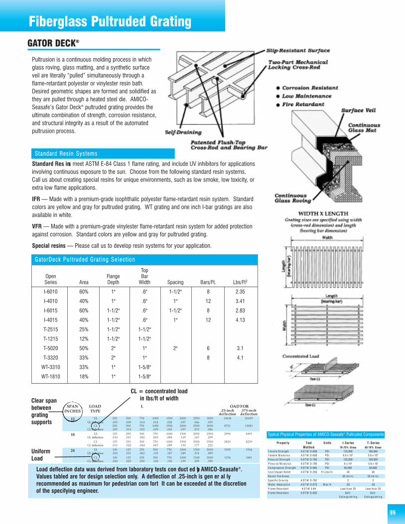
Fiberglass Pultruded GratingGATOR DECK®
Standard Res ins meet ASTM E-84 Class 1 flame rating, and include UV inhibitors for ap pli ca tionsin volv ing con tin u ous ex po sure to the sun. Choose from the fol low ing stan dard resin systems.Call us about creating spe cial resins for unique en vi ron ments, such as low smoke, low tox ic i ty, orextra low flame applications.
IFR — Made with a premium-grade isophthalic poly es ter flame-re tar dant resin system. Stan dardcolors are yellow and gray for pultruded grating. WT grating and one inch I-bar gratings are alsoavail able in white.
VFR — Made with a pre mi um-grade vinylester flame-retardant resin system for added protectionagainst corrosion. Stan dard colors are yellow and gray for pultruded grating.
Special resins — Please call us to develop resin systems for your ap pli ca tion.
Pultrusion is a continuous molding process in whichglass roving, glass mat ting, and a syn thet ic surfaceveil are lit er al ly “pulled” si mul ta neous ly through aflame-re tar dant poly es ter or vinylester resin bath.Desired geometric shapes are formed and solidified asthey are pulled through a heat ed steel die. AMICO-Seasafe’s Gator Deck® pultruded grat ing pro vides theul ti mate com bi na tion of strength, corrosion resistance,and struc tur al in teg ri ty as a result of the automatedpultrusion pro cess.
SSttaannddaarrdd RReessiinn SSyyss tteemmss
TopOpen Flange BarSeries Area Depth Width Spacing Bars/Ft. Lbs/Ft2
I-6010 60% 1" .6" 1-1/2" 8 2.35
I-4010 40% 1" .6" 1" 12 3.41
I-6015 60% 1-1/2" .6" 1-1/2" 8 2.83
I-4015 40% 1-1/2" .6" 1" 12 4.13
T-2515 25% 1-1/2" 1-1/2"
T-1215 12% 1-1/2" 1-1/2"
T-5020 50% 2" 1" 2" 6 3.1
T-3320 33% 2" 1" 8 4.1
WT-3310 33% 1" 1-5/8"
WT-1810 18% 1" 1-5/8"
GGaattoorrDDeecckk PPuulltt rruuddeedd GGrraatt iinngg SSeelleecctt iioonn
Pr op er ty Te st M e th od
U n it s I - S er ie s 70-7 5% Gl as s
T- Se r i es 65-7 0% Gl as s
T e n s i l e S t ren gt h A ST M D -638 PS I 125,000 100,000 T e ns i l e M o d u l u s A S T M D- 638 PS I 6.0 x 1 0 6 5.6 x 1 0 6
F l ex u r al St re n g th A S T M D- 790 PS I 125,000 100,000
F l ex u r al M o du l u s A ST M D -790 PS I 6 x 1 0 6 5.6 x 1 0 6
Co mp re ss i v e S t ren gt h A ST M D -695 PS I 6 5,000 60,000
I z o d Im pa ct No tc h A ST M D -256 F t -L bs / I n 4 0 4 0
Ba rc o l H a r d n e ss 50 (m i n ) 5 0 ( m i n )
Sp ec i f ic G r av i t y A ST M D -792 2 2
W a te r A bs o r pt i o n A ST M D -570 M a x % .0 3 . 03
F l am e R etar da nt A S T M E- 84 Le ss th an 25 Le ss th an 25
F l am e R etar da nt A S T M D- 635 Se l f - Ext i n g u i sh i n g
Se l f - Ext i n g u i sh i n g
Typical Physical Properties of AMICO-Seasafe® Pultruded Com po nents
SPA N L OA D L OA D F OR IN CH ES TY PE .2 5 -in ch
d efl ec tio n .3 75 -in ch d efl ec tio n
12 UL 250 500 750 1000 1500 2000 2500 3000 13636 20455 UL defl ec ti on . 005 . 009 . 014 . 018 . 028 . 037 . 046 . 055
CL 250 500 750 1000 1500 2000 2500 3000 8721 13081 CL defl ec ti on . 007 . 014 . 022 . 029 . 043 . 057 . 072 . 086
18 UL 125 250 500 750 1000 1500 2000 2500 2994 4491 UL defl ec ti on . 010 . 021 . 042 . 063 . 084 . 125 . 167 . 209
CL 125 250 500 750 1000 1500 2000 2500 2820 4229 CL defl ec ti on . 011 . 022 . 044 . 067 . 089 . 133 . 177 . 222
24 UL 100 125 250 500 750 1000 1500 2000 1003 1504 UL defl ec ti on . 025 . 031 . 062 . 125 . 187 . 249 . 374 . 499
CL 100 125 250 500 750 1000 1500 2000 1254 1881 CL defl ec ti on . 020 . 025 . 050 . 100 . 150 . 199 . 299 . 399
30 UL 75 100 125 250 500 750 1000 433 649 UL defl ec ti on . 043 . 058 . 072 . 144 . 289 . 433 . 578
CL 75 100 125 250 500 750 1000 676 1014 CL defl ec ti on . 028 . 037 . 046 . 093 . 185 . 278 . 370
36 UL 75 100 125 250 500 750 215 322 UL defl ec ti on . 087 . 116 . 145 . 291 . 582 . 873
CL 75 100 125 250 500 750 403 604 CL defl ec ti on . 047 . 062 . 078 . 155 . 311 . 466
42 UL 75 100 125 250 500 121 181 UL defl ec ti on . 155 . 207 . 259 . 517 1. 035
CL 75 100 125 250 500 263 395 CL defl ec ti on . 071 . 095 . 119 . 238 . 475
48 UL 75 100 125 250 72 108 UL defl ec ti on . 260 . 347 . 434 . 868
CL 75 100 125 250 180 270 CL defl ec ti on . 104 . 139 . 173 . 347
54 UL 50 75 100 45 68 UL defl ec ti on . 275 . 413 . 550
CL 50 75 100 128 191 CL defl ec ti on . 098 . 147 . 196
Load deflection data was derived from laboratory tests con duct ed by AMICO-Seasafe®.Values tabled are for design selection only. A deflection of .25-inch is gen er al lyrecommended as maximum for pedestrian com fort. It can be exceeded at the discretion of the specifying engineer.
CL = concentrated load in lbs/ft of width
Uniform Load
Clear spanbetween grating supports
99
Fiberglass Pultruded Grating

100
Fiberglass Pultruded GratingLOAD & DEFLECTION DATA
Bearing Bar Type I-Bar
Open Area 60%
Thickness 1.0"
Bearing Bar Centers 1.5"
Resin Systems IFR, VFR
Colors Yellow,
Gray,
or White
Approximate
Weight 2.35 lbs/sq ft
Other Bar Spacing
Available 40% & 50%
Open Area
GATOR DECK® GD-I6010
GATOR DECK® GD-I60151.5" 0.9" 0.6"
1.5"
Bearing Bar Type I-Bar
Open Area 60%
Thickness 1.5"
Bearing Bar Centers 1.5"
Resin Systems IFR, VFR
Colors Yellow or Gray
Approximate Weight 2.83 lbs/sq ft
Other Bar Spacing
Available 40% & 50%
Open Area
1.5" 0.9" 0.6"
1.0"

LOAD & DEFLECTION DATA
Fiberglass Pultruded Grating
GATOR DECK® GD-T5020
101
Fiberglass Pultruded Grating
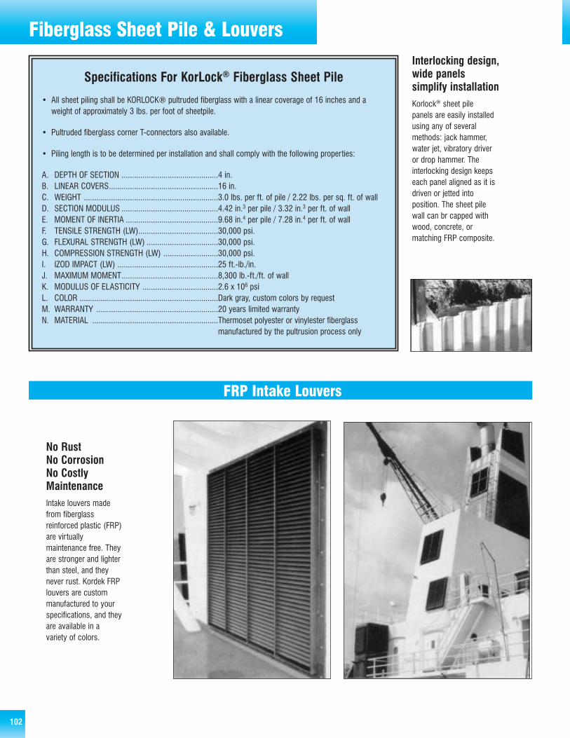
102
Steel Bar GratingFiberglass Sheet Pile & Louvers
FRP Intake Louvers
No RustNo CorrosionNo CostlyMaintenanceIntake louvers madefrom fiberglassreinforced plastic (FRP)are virtuallymaintenance free. Theyare stronger and lighterthan steel, and theynever rust. Kordek FRPlouvers are custommanufactured to yourspecifications, and theyare available in avariety of colors.
Interlocking design,wide panels simplify installationKorlock® sheet pilepanels are easily installedusing any of severalmethods: jack hammer,water jet, vibratory driveror drop hammer. Theinterlocking design keepseach panel aligned as it isdriven or jetted intoposition. The sheet pilewall can br capped withwood, concrete, ormatching FRP composite.
Specifications For KorLock® Fiberglass Sheet Pile
• All sheet piling shall be KORLOCK® pultruded fiberglass with a linear coverage of 16 inches and aweight of approximately 3 lbs. per foot of sheetpile.
• Pultruded fiberglass corner T-connectors also available.
• Piling length is to be determined per installation and shall comply with the following properties:
A. DEPTH OF SECTION ..............................................4 in.B. LINEAR COVERS....................................................16 in.C. WEIGHT ................................................................3.0 lbs. per ft. of pile / 2.22 lbs. per sq. ft. of wallD. SECTION MODULUS ..............................................4.42 in.3 per pile / 3.32 in.3 per ft. of wallE. MOMENT OF INERTIA ............................................9.68 in.4 per pile / 7.28 in.4 per ft. of wallF. TENSILE STRENGTH (LW)......................................30,000 psi.G. FLEXURAL STRENGTH (LW) ..................................30,000 psi.H. COMPRESSION STRENGTH (LW) ..........................30,000 psi.I. IZOD IMPACT (LW) ................................................25 ft.-lb./in.J. MAXIMUM MOMENT..............................................8,300 lb.-ft./ft. of wallK. MODULUS OF ELASTICITY ....................................2.6 x 106 psiL. COLOR ..................................................................Dark gray, custom colors by requestM. WARRANTY ..........................................................20 years limited warrantyN. MATERIAL ............................................................Thermoset polyester or vinylester fiberglass
manufactured by the pultrusion process only

103
Steel Bar GratingFiberglass Cable Tray Systems
19
FIBERGLASS CABLE TRAY SYSTEMSWHY SPECIFY SEASAFE CABLE TRAY?
Available: widths 6 - 9 - 12 - 1824 - 30 - 36
Rung spacing 6 - 9 - 12 - 18
Length120 (10 )240 (20 )
6 side rail systems offer a NEMA 5 loading depth.
Available: widths 6 - 9 - 12 - 1824 - 30 - 36
Rung spacing6 - 9 - 12 - 18
Length120 (10 )240 (20 )
Series 4Loading - NEMA 12C
4 side rail systems offer a NEMA 3 loading depth.
Series 3Loading - NEMA 8C
Available: widths 6 - 9 - 12 - 18 -24 - 30 - 36
Rung spacing6 - 9 - 12 - 18
Length120 (10 )240 (20 )
Series 6BLoading - NEMA 20B
Series 6CLoading - NEMA 20C-S.F.1.5
Series H6CLoading - NEMA 20C-S.F. 2.0
STRAIGHT SECTIONS All tray tested per NEMA FG-1
3 side rail systems offer a NEMA 2 loading depth.
FITTINGS
6 SeriesYou may specify fittings mitered in 30, 45, 60 & 90 radius
4 Series3 Series
Seasafe Cable Tray is U.S. Coast Guard Accepted
1-800-326-8842
Since 1978, Seasafe Fiberglass Cable TraySystems have been tested and proven in the harshenvironment of the offshore oil and gas industry.Subject to the corrosive conditions inherent inpetroleum products, plus the daily punishment ofexposure to wind, weather and saltwater – SeasafeCable Tray has stood up!
Seasafe Cable Tray gives you the load capacityof steel plus the inherent characteristics affordedby our in-house Pultrusion Technology:
non-conductive, non-magnetic and corrosion-resistant. Although light in weight, their strength-to-weight ratio surpasses that of equivalent steelproducts. Seasafe Cable Tray will not rust, nor do
they ever require painting. Available in bothpolyester and vinylester resin systems, they aremanufactured to meet ASTM E-84, Class 1 FlameRating and self-extinguishing requirements ofASTM D-635.
A surface veil is applied during the pultrusionprocess to ensure a resin-rich surface for superiorcorrosion resistance as well as an ultravioletexposure barrier. Cable Tray comes in two colors:Gray (polyester resin) and Beige (vinylester resin).Custom colors are available on request.
The NEMA loadings listed in this brochure areload-tested in accordance with NEMA FG-1guidelines.
Fiberglass Cable Tray Systems

104
Seasafe custom structural fabrication provides the solution to your corrosion problems. You get high-strength, lightweight,low maintenance fiberglass reinforced composite products to compensate for the shortcomings of conventional materials.Pound for pound, FRP structural shapes are stronger than steel.
Features ofFiberglass Materials
• Corrosion Resistant
• High Strength
• Lightweight
• Low Maintenance
• Low Life-Cycle Cost
• Electrically Non-Conductive
• Fire Retardant
• Ultraviolet Protection
• Low Thermal Conductivity
• Non-Magnetic
• Dimensional Stability
• Easy Assembly
Industries Serviced
• Food Processing
• Chemical Processing
• Water/Waste Water Treatment
• Recreational/Leisure
• Metal Finishing
• Military/Government
• Beverage
• Utilities
• Oil & Gas
• Marine
• Mining/Refining
• Pharmaceuticals
• Pulp & Paper
• Transportation
Structural ShapesIn-house fiberglass pultrusion technology enablesSeasafe to present an extensive line of FRP structural shapes. Standard configurations includeangle, channel, square tube, round tube, solid bar,flat sheet, wide flange beam and I-beam. All arereadily available in a wide range of sizes and thicknesses.
Handrail & Ladder Systems
Resin SystemsSeasafe FRP products are available in standard corrosion resistant isophthalic polyester or premium vinylester resin systems. Both resins include UV inhibitors and are Class 1 Fire Retardant per ASTM E84.
Handrails
Pultruded Grating Molded Grating Compression-Molded Grating
Pultruded Stair Treads Molded Stair Treads Stair Tread Covers
Ladders & Caged Ladders
Fiberglass Fabrication Services
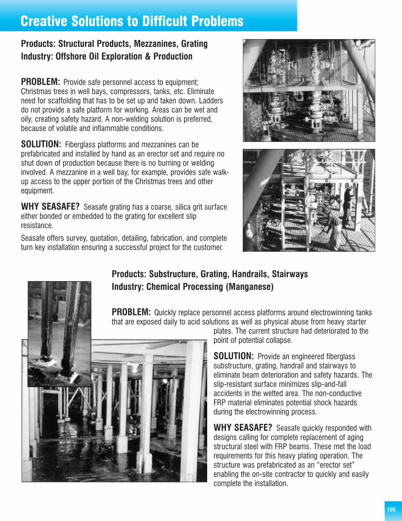
105
Steel Bar GratingCreative Solutions to Difficult Problems
Products: Structural Products, Mezzanines, GratingIndustry: Offshore Oil Exploration & Production
PROBLEM: Provide safe personnel access to equipment;Christmas trees in well bays, compressors, tanks, etc. Eliminateneed for scaffolding that has to be set up and taken down. Laddersdo not provide a safe platform for working. Areas can be wet andoily, creating safety hazard. A non-welding solution is preferred,because of volatile and inflammable conditions.
SOLUTION: Fiberglass platforms and mezzanines can beprefabricated and installed by hand as an erector set and require noshut down of production because there is no burning or weldinginvolved. A mezzanine in a well bay, for example, provides safe walk-up access to the upper portion of the Christmas trees and otherequipment.
WHY SEASAFE? Seasafe grating has a coarse, silica grit surfaceeither bonded or embedded to the grating for excellent slipresistance.
Seasafe offers survey, quotation, detailing, fabrication, and completeturn key installation ensuring a successful project for the customer.
Products: Substructure, Grating, Handrails, StairwaysIndustry: Chemical Processing (Manganese)
PROBLEM: Quickly replace personnel access platforms around electrowinning tanksthat are exposed daily to acid solutions as well as physical abuse from heavy starter
plates. The current structure had deteriorated to thepoint of potential collapse.
SOLUTION: Provide an engineered fiberglasssubstructure, grating, handrail and stairways toeliminate beam deterioration and safety hazards. Theslip-resistant surface minimizes slip-and-fallaccidents in the wetted area. The non-conductiveFRP material eliminates potential shock hazardsduring the electrowinning process.
WHY SEASAFE? Seasafe quickly responded withdesigns calling for complete replacement of agingstructural steel with FRP beams. These met the loadrequirements for this heavy plating operation. Thestructure was prefabricated as an “erector set”enabling the on-site contractor to quickly and easilycomplete the installation.

106
Steel Bar Grating
Products: Structural Products,Grating, Stairs, HandrailsIndustry: Waste Water Treatment
PROBLEM: Design and build safe personnelaccess to 17 carbon filter tanks, each 13 feethigh, in a wet and slippery work environment.
SOLUTION: Install an FRP platform with stairsand handrails, with slip-resistant grating andstair treads. (Platforms for two tanks shownhere.)
WHY SEASAFE? To ensure accuracy and easeof assembly on-site, these platforms wereassembled and inspected by the customer atSeasafe’s plant prior to shipping to Asia.Seasafe completely assembles each fabricatedstructure at our plant then separates it into
sub-assemblies for shipment. This allows quick and trouble-free erection in the field by contractors. We proved to the customerthat we could take the design concept and turn it into a finished structure, within their schedule and budget.
Products: Structural Grating, Handrails, StairwaysIndustry: Chemical Processing
PROBLEM: Efficiently loadcorrosive chemicals into tank trucksfor transfer to job site or end user.Extend life of loading facility. Providesafe working environment.
SOLUTION: Replace metalstructure with FRP platform andwalkways, eliminating maintenanceand replacement requirements.Provide a strong but lightweightplatform with a hinged section forsafe, quick, easy access to tanktruck ports in various locations andat various heights.
WHY SEASAFE? Seasafedesigned a platform that not onlymet all the job requirements, butwas capable of being erected without cranes or heavy lifting equipment.
Accessing Tanks & Filling Tank Trucks
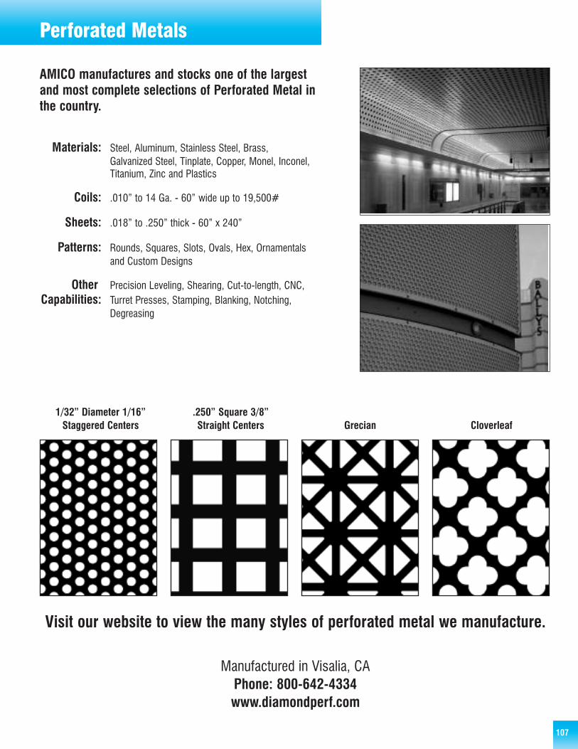
107
Perforated Metals
AMICO manufactures and stocks one of the largestand most complete selections of Perforated Metal inthe country.
Materials: Steel, Aluminum, Stainless Steel, Brass, Galvanized Steel, Tinplate, Copper, Monel, Inconel, Titanium, Zinc and Plastics
Coils: .010” to 14 Ga. - 60” wide up to 19,500#
Sheets: .018” to .250” thick - 60” x 240”
Patterns: Rounds, Squares, Slots, Ovals, Hex, Ornamentals and Custom Designs
Other: Precision Leveling, Shearing, Cut-to-length, CNC,Capabilities: Turret Presses, Stamping, Blanking, Notching,
Degreasing
Visit our website to view the many styles of perforated metal we manufacture.
Manufactured in Visalia, CAPhone: 800-642-4334www.diamondperf.com
1/32” Diameter 1/16” .250” Square 3/8”Staggered Centers Straight Centers Grecian Cloverleaf

108
Notes
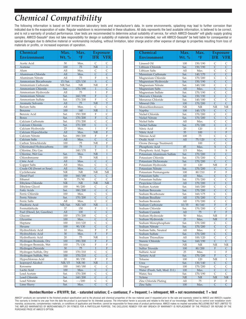
Chemical CompatibilityThe following information is based on full immersion laboratory tests and manufacturer’s data. In some environments, splashing may lead to further corrosion thanindicated due to the evaporation of water. Regular washdown is recommended in these situations. All data represents the best available information, is believed to be correct,and is not a warranty of product performance. User tests are recommended to determine actual suitability of service, for which AMICO-Seasafe® will gladly supply gratingsamples. AMICO-Seasafe® does not take responsibility for design or suitability of materials for service intended, nor will AMICO-Seasafe® be held liable for consequential orspecial damages due to defective material or workmanship including, without limitation, labor charge and/or other expense of damage to properties resulting from loss ofmaterials or profits, or increased expenses of operation.
Chemical Max. Max. ExposureEnvironment Wt. % ºF IFR VFRAcetic Acid 50 Max. C CAcetone 100 75 NR IAlum All Max. C CAluminum Chloride All Max. C CAluminum Nitrate All 75 F SAmmonium Bircarbonate 15/Sat. 125/130 S CAmmonium Carbonate NR/Sat. NR NR FAmmonium Chloride Sat. 170/190 I CAmmonium Hydroxide All 75 I FAmmonium Nitrate Sat. 160/190 F CAmmonium Sulfate Sat. 170/200 F CAromatic Solvents All 75 NR TBarium Salts All Max. C CBenzene 100 140 NR IBenzoic Acid Sat. 150/200 F CBorax Sat. 170/200 F CCalcium Carbonate Sat. 170/200 C CCalcium Chloride Sat. 170/200 C CCalcium Hydroxide 25 Max. I FCalcium Hypochlorite All Max. NR FCalcium Nitrate Sat. 180/200 F FCalcium Salts All Max. C CCarbon Tetrachloride 100 75 NR FChlorinated Hydrocarbons 100 75 T TChlorine, Dry Gas 140/170 T IChlorine, Wet Gas Sat. Max. NR IChlorobenzene 100 75 NR ICitric Acid All Max. C CCopper Salts All Max. C CCrude Oil (Sweet or Sour) All Max. C CCyclohexane NR NR NR NRDiesel Fuel 100 160/180 C CEthanol 50 75/90 C CEthylene Chloride NR NR NR NREthylene Glycol 100 90/200 C CFatty Acids Sat. 180/200 C CFerric Chloride 100 Max. C CFerric Nitrate Sat. 170/200 C CFerric Salts All Max. C CFluoboric Acid NR/Sat. NR/165 NR IFormaldehyde 37 150 F IFuel (Diesel, Jet, Gasoline) All 100 C CGlucose 100 170/200 C CGlycerine 100 Max. C CHeptane 100 110/120 C CHexane 100 90/130 C CHydrochloric Acid 10 Max. F FHydrochloric Acid 30 Max. F FHydrofluoric Acid 20 75 NR IHydrogen Bromide, Dry 100 190/200 F FHydrogen Bromide, Wet 100 75/130 F FHydrogen Peroxide 30 75 I FHydrogen Sulfide, Dry 100 170/210 C CHydrogen Sulfide, Wet 100 170/210 C CHypochlorous Acid 20 80/150 F FIsopropyl Alcohol NR/15 NR/80 NR IKerosene 100 140/180 C CLactic Acid 100 Max. C CLead Acetate Sat. 170/200 C CLead Chloride Sat. 140/200 C CLead Nitrate Sat. —/200 C CLime Slurry Sat. Max. C C
Chemical Max. Max. ExposureEnvironment Wt. % ºF IFR VFRLinseed Oil 100 150/190 C CLithium Chloride Sat. 150/190 C CLithium Salts All Max. C CManesium Carbonate Sat. 140/170 C CMagnesium Chloride Sat. 170/200 C CMagnesium Hydroxide Sat. 150/190 C CMagnesium Nitrate Sat. 140/180 C CMagnesium Salts All Max. C CMagnesium Sulfate Sat. 170/190 C CMercuric Chloride Sat. 150/190 C CMerurous Chloride Sat. 140/180 C CMineral Oils 100 170/200 C CMonochlorobenzen NR NR NR NRNaptha 100 140/170 C CNickel Chloride Sat. 170/200 C CNickel Nitrate Sat. 170/200 C CNickel Salts All Max. C CNickel Sulfate Sat. 170/200 C CNitric Acid 20 120 I FNitric Acid 35 100 I FNitrous Acid 100 75 C COxalic Acid All 75/120 C COzone (Sewage Treatment) 100 C CPhosphoric Acid 85 Max. S CPhosphoric Acid, Super 115 Max. I SPotassium Aluminum Sulfate Sat. 170/200 C CPotassium Chloride Sat. 170/200 C CPotassium Dichromate Sat. 170/200 C CPotassium Hydroxide 10 120 NR FPotassium Nitrate Sat. 170/200 C CPotassium Permangante 100 80/210 F FPotassium Salts All Max. C CPotassium Sulfate Sat. 170/200 C CPropylene Glycol All 170/200 C CSodium Acetate Sat. 160/200 C CSodium Benzoate Sat. 170/200 C CSodium Bicarbonate Sat. 160/175 C CSodium Bisulfate All 170/200 C CSodium Bromide All 170/200 C CSodium Carbonate 10/35 80/160 F FSodium Chloride Sat. 170/200 C CSodium Cyanide All 75 F FSodium Hydroxide 50 Max. NR FSodium Hydroxide 25 Max. NR FSodium Monophosphate Sat. 170/200 C CSodium Nitrate Sat. 170/200 C CSodium Salts, Neutral All Max. C CSodium Sulfate Sat. 170/200 C CSodium Thiosulfate All 100/120 C CStannic Chloride Sat. 160/190 C CStyrene NR NR NR NRSulfur Trioxide 100 80/200 F CSulfuric Acid 25 Max. I FTartaric Acid Sat. 170/200 F CToluene 100 120 NR IUrea Sat. 130/140 C CVinegar 100 170/200 C CWater (Fresh, Salt, Mod. D.I.) 100 Max. C CWater, Sea Sat. 170/190 C CXylene NR NR NR NRZinc Chloride Plating All 75 F FZinc Salts 100 Max. C C
Number/Number = IFR/VFR; Sat. - saturated solution; C = contiuous; F = frequent; I = infrequent; NR = not recommended; T = testAMICO® products are warranted to the finished product specification and to the physical and chemical properties of the raw material used if requested prior to the sale and expressly stated by AMICO and AMICO’s supplier.This warranty is limited to one year from the date the product is purchased for its intended purpose. The information herein is accurate and reliable to the best of our knowledge. AMICO has no control over installation work-manship, accessories, complementary materials, or conditions of application and therefore, cannot be responsible for these areas of product performance. AMICO makes no implied warranties INCLUDING BUT NOT LIMITED TOTHE IMPLIED WARRANTIES OF MERCHANTABILITY OR FITNESS FOR A PARTICULAR PURPOSE. THE EXCLUSIVE REMEDY FOR ANY BREACH OF WARRANTY IS REPLACEMENT OF THE PRODUCT OR REFUND OF THEPURCHASE PRICE AT AMICO'S OPTION.

QUALITY PRODUCTS – COAST TO COAST
Locations coast to coast to serve you better!
Birmingham, AL 800-366-2642
Chicago, IL 800-238-0322
Dayton, TX 800-622-5765
Denver, CO 800-425-5558
Fontana, CA 800-962-0100
Greenville, SC 800-476-4430
Houston, TX 800-433-9945
Lafayette, LA 800-326-8842
Lakeland, FL 800-487-2511
N. Kansas City, MO 800-472-3121
Orem, UT 800-645-0340
Seattle, WA 800-859-5363
Visalia, CA 800-642-4334
Wilmington, DE 800-476-4430
CANADA
Burlington, ON 800-663-4474
Montreal, PQ 800-361-0009
Vancouver, BC 800-665-4474
01/07-13M


![CAILLEBOTIS MÉTAL BRISE-SOLEIL & AUVENT & APPLICATIONS ... · La protection en priorité, planchers et garde-corps en harmonie. [ 21 ] DCAB. CAILLEBOTIS PRESSÉ DROIT - ACIER GALVANISÉ](https://static.fdocuments.net/doc/165x107/5f121e72fc1883567e1a663b/caillebotis-mtal-brise-soleil-auvent-applications-la-protection.jpg)