CAEA v145 update HPC - CAE Associates | ANSYS …€¦ · · 2017-07-18It’s all abo t getting...
44
Agenda 9:00 – Welcome 1:00 - Computing Utilities 9:00 Welcome — Introductions — What is new at CAEA 9:15 - Mechanical Demonstration CAD ti tiliti ( ithi th CAD 1:00 Computing Utilities — HPC — GPU — RSM HPC Parametric Pack — CAD connection utilities (within the CAD API) — Mechanical setup • Rigid Bodies, Joints, contact, meshing • Using the Mechanical model as a template — HPC Parametric Pack 1:30 - CFD Update — Design iteration/optimization using CFX — Shape optimization using Fluent • Using the Mechanical model as a template. — Submodeling (parametric mesh refinement) 10:30 - Break 10:45 - Result evaluation: What do I do i h hi ? — 1-way FSI 3:00 Break 3:15 – ANSYS Customization Toolkit — What is ACT? with this stress? — Fatigue calculation — Automating the process • Direct Optimization What is ACT? — Examples (acoustics, wind load, DYNA drop test. 4:00 Engineering Knowledge Manager 4:15 ANSYS Composite Prep Post • RSO(robust design, DFSS) — Fracture 12:00 – Lunch 4:15 ANSYS Composite Prep-Post 4:30 MAPDL 1
Transcript of CAEA v145 update HPC - CAE Associates | ANSYS …€¦ · · 2017-07-18It’s all abo t getting...
Agenda
9:00 – Welcome 1:00 - Computing Utilities 9:00 Welcome— Introductions— What is new at CAEA
9:15 - Mechanical DemonstrationCAD ti tiliti ( ithi th CAD
1:00 Computing Utilities— HPC — GPU— RSM
HPC Parametric Pack— CAD connection utilities (within the CAD API)
— Mechanical setup • Rigid Bodies, Joints, contact, meshing• Using the Mechanical model as a template
— HPC Parametric Pack 1:30 - CFD Update
— Design iteration/optimization using CFX— Shape optimization using Fluent
• Using the Mechanical model as a template. — Submodeling (parametric mesh refinement)
10:30 - Break 10:45 - Result evaluation: What do I do
i h hi ?
— 1-way FSI 3:00 Break 3:15 – ANSYS Customization Toolkit
— What is ACT?with this stress? — Fatigue calculation— Automating the process
• Direct Optimization
What is ACT?— Examples (acoustics, wind load, DYNA
drop test. 4:00 Engineering Knowledge Manager 4:15 ANSYS Composite Prep Post• RSO(robust design, DFSS)
— Fracture 12:00 – Lunch
4:15 ANSYS Composite Prep-Post 4:30 MAPDL
1

High Performance C tiComputing
CAE Associates Inc. and ANSYS Inc. Proprietary© 2013 CAE Associates Inc. and ANSYS Inc. All rights reserved.

High Performance Computing
In this day and age engineers are asked to solve more and more complex In this day and age engineers are asked to solve more and more complex problems, but they are not given any additional time to accomplish this.
It’s all abo t getting better insight into prod ct beha ior q icker! It’s all about getting better insight into product behavior quicker!
HPC enables high-fidelity — Include details - for reliable results— “Getting it right the first time”— Innovate with confidence
HPC enables design exploration & optimization— Consider multiple design ideas— Optimize the design— Ensure performance across range of conditions
3

Parallel Performance Options
Shared Memory ANSYS (SMP) Shared Memory ANSYS (SMP)— Multiple processors on one machine, all accessing the same RAM— Limited by memory bandwidth
Tops out around 8 cores— Tops out around 8 cores
Distributed ANSYS (MPP)— Can run over a cluster of machines OR use multiple processors on one
machine.— In the case of clusters, limited by interconnect speed
E t d f t l b f— Extends performance to a larger number of cores
4
HPC Using GPU
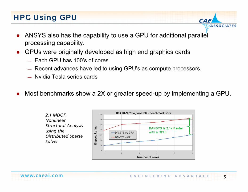
ANSYS also has the capability to use a GPU for additional parallel ANSYS also has the capability to use a GPU for additional parallel processing capability.
GPUs were originally developed as high end graphics cardsEach GPU has 100’s of cores— Each GPU has 100 s of cores
— Recent advances have led to using GPU’s as compute processors. — Nvidia Tesla series cards
Most benchmarks show a 2X or greater speed-up by implementing a GPU.
2.1 MDOF, Nonlinear Structural Analysis using theusing the Distributed Sparse Solver
5

GPU Accelerator Capability
Targeted hardware Targeted hardware
NVIDIA Tesla C2075Tesla M2075
NVIDIA Tesla
M2090
NVIDIAQuadro
6000
NVIDIAQuadro K5000†
NVIDIATesla K10
NVIDIATesla K20
Power (W) 225 250 225 122 250 250
Memory 6 GB 6 GB 6 GB 4 GB 8 GB 6 to 24 GBMemoryMemory
Bandwidth (GB/s)
144 177.4 144 173 320 288
Peak S d DP 515 665 515 95 190 1728Speed DP (GFlops)
515 665 515 95 190 1728
6

ANSYS v14.5 – Multi-GPU per Node
Multiple GPUs per machine are now supported (v14 5 Mechanical) Multiple GPUs per machine are now supported (v14.5 Mechanical)— Supports single workstation with multiple GPUs— Supports cluster with each compute node having multiple GPUs
Both shared and distributed memory parallel modes are supported— Both shared and distributed memory parallel modes are supported
7
FEA Benchmark Problem
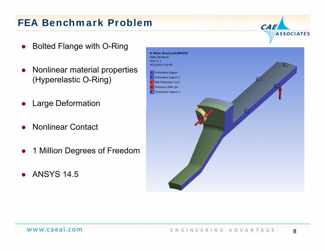
Bolted Flange with O-Ring Bolted Flange with O-Ring
Nonlinear material properties (H perelastic O Ring)(Hyperelastic O-Ring)
Large Deformation
Nonlinear Contact
1 Million Degrees of Freedom
ANSYS 14 5 ANSYS 14.5
8
High End Workstation
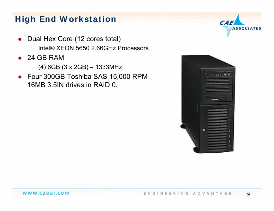
Dual Hex Core (12 cores total) Dual Hex Core (12 cores total) — Intel® XEON 5650 2.66GHz Processors
24 GB RAM (4) 6GB (3 2GB) 1333MH— (4) 6GB (3 x 2GB) – 1333MHz
Four 300GB Toshiba SAS 15,000 RPM 16MB 3.5IN drives in RAID 0.
9

FEA Benchmark Performance
Parallel Improvements Parallel Improvements
1 Million DOF Benchmark ‐ Distributed Parallel
12000
14000
16000
8000
10000
12000
me (secs)
v14.5
4000
6000Run Tim
v13.0
v14.0
0
2000
0 2 4 6 8 10 12 14
10
0 2 4 6 8 10 12 14Number of Cores

FEA Benchmark Performance
1 Million DOF Benchmark
12000
14000
1 Million DOF Benchmark
10000
12000
6000
8000
Run Time (secs)
No GPU
GPU
2000
4000
0
2000
0 2 4 6 8 10 12 14
11
Number of Cores

Take Advantage of Adding GPUs @ v14.5
25
Day V14sp-5
Model
Results for Distributed ANSYS 14.5 Preview and Xeon 8-Core CPUs
19
20
of
Jobs
Per
Model
Higheris
Better
1210
15
ical
Num
ber
Turbine geometry
1.6x Speedup with 2 GPUs
8 8
5
SYS
Mec
hani
g y2,100 K DOFSOLID187 FEsStatic, nonlinearOne iterationANSYS M h i l14 5
0
AN
S
Results from HP Z820; 2 x Xeons( 6 C f l 8) 28GB
ANSYS Mechanical14.5Direct sparse solver
Xeon E5-2687W 8 Cores + Tesla C2075
Xeon E5-2687W 8 Cores + 2 x Tesla C2075
12
(16 Cores, use of only 8) 128GB memory, Win7; 2 x Tesla C2075

CFX Benchmark Problem
Flow through a complicated grille Flow through a complicated grille
15 Million Elements
3-D, Steady State, Incompressible Flow
k-ω Turbulence Model
13

CFX Benchmark Performance
CFX Parallel Performance
8
9
CFX Parallel Performance
6
7
p
4
5
ver S
pped
U
CFX1
2
3
Solv
0
1
0 2 4 6 8 10 12 14
14
0 2 4 6 8 10 12 14
# Cores

ANSYS Fluent Scaling Achievement v14.5
Good Scalability at ~18K cells Good Scalability at ~18K cells per core
— 150M cell model Non-reactive species— Non-reactive species
— LES Turbulence— Running on Cray XE6
300
350
400
r day Rating
Ideal
200
250
300
atio
ns p
er
Number Cells/Core Efficiency
50
100
150
Sim
ula of Cores Cells/Core Efficiency
2048 73K 100%
4096 36K 98%
5632 26K 88%2048 3072 4096 5120 6144 7168 8192Number of Cores
(10 time steps)
5632 26K 88%
6656 22K 81%
7680 19K 74%
8192 18K 70%
15
8192 18K 70%

So far we have seen how to speed up the solution of a Single Design Point
Evolution of Parametric Simulation
So far we have seen how to speed up the solution of a Single Design Point— Solves a single simulation involving single or multiple physics.
• One set of loads, geometry, materials, and other settingsConcerned about robustness speed accuracy ease of use and engineering— Concerned about robustness, speed, accuracy, ease of use and engineering results.
Is this the best design? Is this the best design? gHow can I improve performance? Can I reduce weight or cost?
gHow can I improve performance? Can I reduce weight or cost?
Doesn’t provide What is limiting performance? Is this a robust design? What is limiting performance? Is this a robust design?
direction for design improvement
16
Evolution of Parametric Simulation
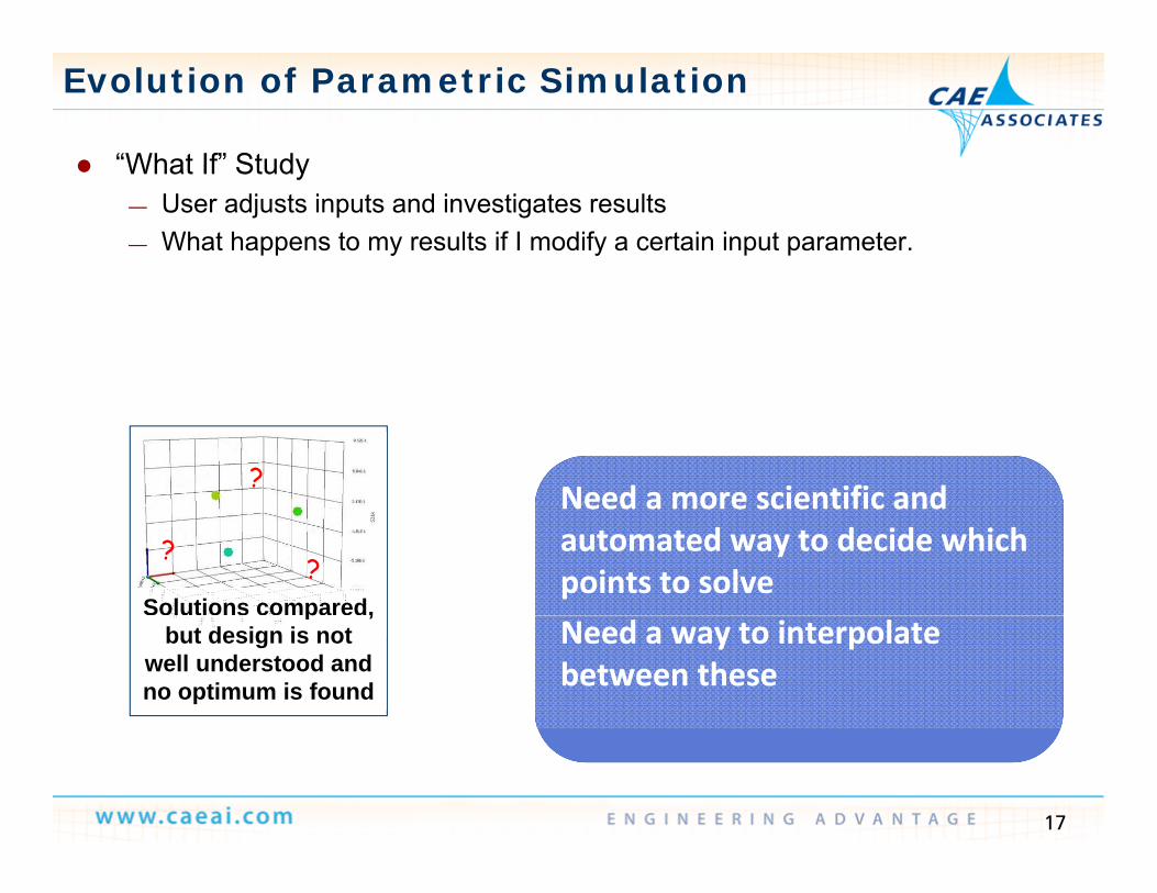
“What If” Study What If Study— User adjusts inputs and investigates results— What happens to my results if I modify a certain input parameter.
?Need a more scientific andNeed a more scientific and
??
Solutions compared,
Need a more scientific and automated way to decide which points to solve
Need a more scientific and automated way to decide which points to solve
p ,but design is not
well understood and no optimum is found
Need a way to interpolate between these Need a way to interpolate between these
17
Evolution of Parametric Simulation
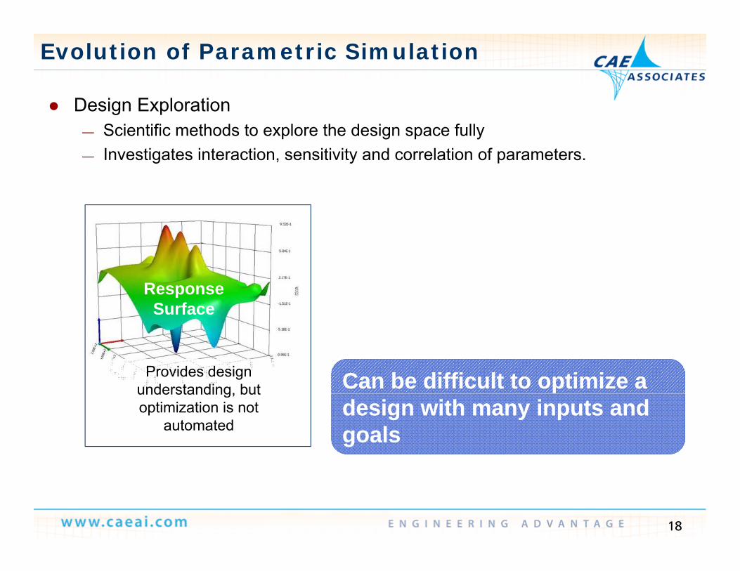
Design Exploration Design Exploration— Scientific methods to explore the design space fully— Investigates interaction, sensitivity and correlation of parameters.
Response Surface
Can be difficult to optimize a Can be difficult to optimize a Provides design understanding, but
design with many inputs and goalsdesign with many inputs and goals
understanding, but optimization is not
automated
18

Evolution of Parametric Simulation
Optimization Optimization— Searches the design space for optimal candidates, given user-defined goals
and priorities— Amplifies the importance of the previous technologyAmplifies the importance of the previous technology— Adds requirements for: advanced optimization algorithms to efficiently search
for candidates, comparative reporting
Real world inputsReal world inputsReal-world inputs typically have some variation and may require
Real-world inputs typically have some variation and may require a more “robust design” goala more “robust design” goalSolutions may be
too sensitive to input variability
19
y
Robust Design
Evolution of Parametric Simulation
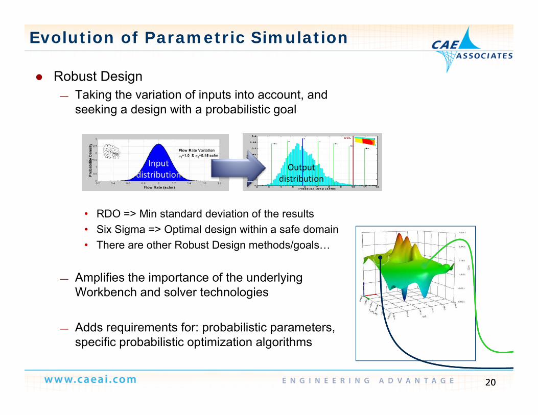
Robust Design— Taking the variation of inputs into account, and
seeking a design with a probabilistic goal
Input distribution
Output distribution
• RDO => Min standard deviation of the results• Six Sigma => Optimal design within a safe domain
distribution
g p g• There are other Robust Design methods/goals…
— Amplifies the importance of the underlying Workbench and solver technologies
— Adds requirements for: probabilistic parameters, ifi b bili ti ti i ti l ith
20
specific probabilistic optimization algorithms

From Single Physics to Robust Design
Robust DesignRobust Design is an
Optimization
Robust Design•Six Sigma Analysis•Probabilistic Algorithms•Design for Variation
gANSYS Advantage
“What if”
Design Exploration•DOE, Response Surfaces, Correlation Sensitivity
•AlgorithmsDesign for Variation
Multiphysics
What if Study•Parametric Platformi l
Correlation, Sensitivity,
Single Physics Solution
Solution•Integration Platform
•Simultaneous Solve
21
Solution•Accuracy, robustness, speed…

Workbench Platform Parametric Studies
We previously demonstrated how using We previously demonstrated how using parameters is a powerful way to perform design studies.
Parameters are defined in the Parameters are defined in the applications; managed at the project level
Each configuration is managed as a “design point”design point
22

Design Points: Overview
There are several types of There are several types of parameters
• Geometry (CAD) parameters• Material propertiesa e a p ope es• Mesh controls• Loads/Boundary conditions• Output Parameters
— Once set-up these parameters can be controlled from the Workbench project page (design point table)point table).
— All phases of the project can be updated automatically for each set of parameters with no need pfor scripting.
23

Once parameterized we can set up an entire Design of Experiments with
DOE Simulations
Once parameterized we can set up an entire Design of Experiments with just the click of a button in DesignXplorer
24
RSM
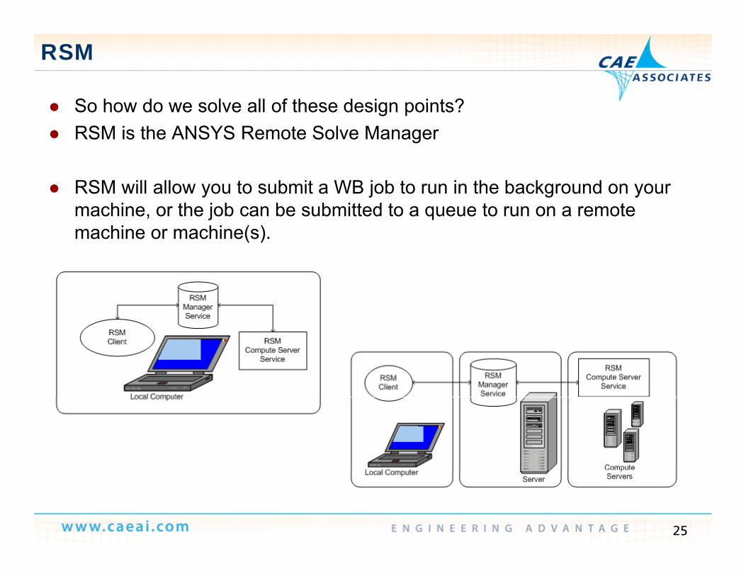
So how do we solve all of these design points? So how do we solve all of these design points? RSM is the ANSYS Remote Solve Manager
RSM will allow you to submit a WB job to run in the background on your machine, or the job can be submitted to a queue to run on a remote machine or machine(s).
25

Sequential Design Point Update
At v13 0 design points had to be At v13.0, design points had to be solved sequentially
With potentiall h ndreds of long With potentially hundreds of long-running design points, this can be time prohibitive.
A CCD DOE with 8 parameters will require 81 runs, 10 parameters will require 149 runs!require 149 runs!
dp1 dp2 dp3 Dpn
26

Simultaneous Design Point Update
At v14 0 the capability to update design points At v14.0 the capability to update design points simultaneously via RSM was added.
B r nning se eral design points sim ltaneo sl the By running several design points simultaneously, the overall analysis time is greatly reduce.
dp1 Scaling is ideal, 2 jobs will run twice as fast on 2
machines.
dp1
dp2
Project on
dp2
dp3Project on client
dp3
27
Dpn

License Usage v14.0
ANSYS products will “grab” licenses as each ANSYS products will grab licenses as each software component is executed.
To pdate n design points sim ltaneo sl o
LicenseServer
To update n design points simultaneously you need n * the licenses.
dp1 This makes running simultaneous design points cost prohibitive.
dp1
ddp2
Project on client
It can also make design points prone to failure if not enough licenses were available during the
dp3client
28
not enough licenses were available during the update process. Dpn

HPC Parametric Packs
At v14 5 ANSYS introduced HPCNumber of Simultaneous Design Points Enabled
At v14.5 ANSYS introduced HPC Parametric Packs.
The allo sers to r n n design points
64
They allow users to run n design points simultaneously, “amplifying” the base license(s)
Scalable similar to ANSYS HPC Packs— Scalable, similar to ANSYS HPC Packs — Enabled by Workbench, Design Points,
Reserved Licensing and RSM.32
8
16
2
8
1
4
3 4 5
29
2Number of HPC Parametric Pack Licenses1 3 4 5

Products Amplified by HPC Parametric Pack
At R14 5 the following products will be enabled (i e multiplied in At R14.5, the following products will be enabled (i.e., multiplied in simultaneous usage) through the HPC Parametric Pack:
— ANSYS CFD, ANSYS CFD Solver , ANSYS CFD PrepPost ANSYS CFD-Post — ANSYS CFX, ANSYS CFX Solver — ANSYS Fluent, ANSYS Fluent Solver — ANSYS Fluent PEM Fuel Cell Module, ANSYS Fluent SOFC Fuel Cell Module
— ANSYS Mechanical, ANSYS Mechanical EMAG, ANSYS Mechanical CFD-Flo — ANSYS Multiphysics
— ANSYS HPC, ANSYS HPC Pack— ANSYS HPC Workgroup, ANSYS HPC Enterprise
ANSYS M hi— ANSYS Meshing— ANSYS TurboGrid
— ANSYS Polyflow, ANSYS Polyflow Solver
30
S S o y o , S S o y o So e— ANSYS Polyflow BlowMolding, ANSYS Polyflow Extrusion

Other RSM v14.5 Enhancements
New ANSYS Remote Solve Manager Setup Wizard New ANSYS Remote Solve Manager Setup Wizard— The ANSYS Remote Solve Manager Setup Wizard can guide you through the
process of setting up and configuring Remote Solve Manager.
Specify Maximum Number Jobs and Maximum Processors Per Job for Design Point Updates via RSM
For design point updates submitted to RSM a new Specify Maximum— For design point updates submitted to RSM, a new Specify Maximum Number of Jobs option is available. When you select this option, design points are divided into groups and submitted in multiple jobs, up to the specified maximum number of jobs.
— The Max Number of Processes per Job property allows you to specify the maximum number of processes to be used by the solver for each job in the update.
Improved File Transfer Performance — In this release, the Remote Solve Manager provides faster, more efficient file
transfers, reducing the overhead associated with performing solutions via RSM
31
RSM.

Local Geometry Update
We have two challenges in updating geometry remotely: We have two challenges in updating geometry remotely:— CAD often cannot be accessed on the compute nodes (particularly with Linux
cluster computing).— We have royalty issues with enabling multiple geometry sessions or CADWe have royalty issues with enabling multiple geometry sessions or CAD
connections via HPC Parametric Packs
At v14 5 we therefore require geometry update to occur locally (in serial) At v14.5 we therefore require geometry update to occur locally (in serial) on the client before submitting design points to RSM.
The remainder of the design point update (meshing pre processing The remainder of the design point update (meshing, pre-processing, solution, …) occur on the remote computing resource.
— This is different than previous versions where only the solution was sent to RSMRSM.
32

Time Required for a Parametric Study
dp3dp4
f points
HPC parametric packs amplify both solver licenses and HPC licenses ll i d i ll d
One set of
dp1dp2dp3
Serie
s of
Design p
Unused Cores
Without HPCallowing you to drastically reduce time to innovation
Solver keys
Unused Cores
One set of solvers and 1 HPC Parametric Pack 94% Reduced Time
Four sets of solver keysOR
+ 1 HPC Pack94% Reduced Time to Innovation
33
It’s All About Parametric Simulations!
ANSYS Workbench advantages— Automated, parametric, and persistent all physics and applications
O ti t i biliti D i E l ti O ti i ti d Si— Our native parametric capabilities Design Exploration, Optimization and Six Sigma analyses, without complex programming!
— Both fully integrated tools and links to partner solutions
Our value proposition to YOU— “We’ll help you gain the deep insights necessary to optimize
performance through parametric simulation and produce better productsperformance through parametric simulation and produce better products, faster”
34

Reserved Licensing
HPC Parametric Packs HPC Parametric Packs actually amplify a reserved License Set rather than individual keys. Reservedindividual keys.
It is up to the user to ensure that the reserved license set is adequate.
dp1
LicenseS
Reserved LicenseSet
is adequate. An end-user benefit of
reserving licenses is that design points should not fail
dp2Server
design points should not fail due to a lack of available licenses. dp3Project on
client
Dpn
35

Reserved Licensing
To explain License Tracking we must first explain reserved licensing To explain License Tracking, we must first explain reserved licensing
HPC Parametric Packs can be Added to the Reserved License Set to Amplify all
the qualified keys.
36

Design Points: Overview
It is important to note that because the License Server holds the identifier It is important to note that because the License Server holds the identifier – both the submission machine and the machine(s) where the design points are run must point to the same license server.
License Server
Client
DP1 DP2 DP3 DPn
37

HPC Parametric P kPack
Example Applications
CAE Associates Inc. and ANSYS Inc. Proprietary© 2013 CAE Associates Inc. and ANSYS Inc. All rights reserved.

Rear Axle Model
Evaluating Material Properties Evaluating Material Properties — Large deflection non-linear static model
investigating design sensitivity to material propertiesp p
— Input parameter: material property (8 design points)
• Detail:– Sparse matrix solver running incore; 4 load steps– 1,393,811 nodes, 829,701 elements (4,151,766 DOF)– Hardware: Dell workstation with dual Intel Xeon E5‐2690 (2.90 GHz, 16 cores), 256 GB memory,
all jobs running 2 coresall jobs running 2 cores
Licensing Solution• 1 ANSYS Mechanical2 ANSYS HPC P t i P k• 2 ANSYS HPC Parametric Packs
Result/Benefit• 5x speedup over sequential execution
39
• Easier and fully automated workflow!
Acknowledgment: Paul Schofield and Jiaping Zhang, ANSYS Houston
Mixing Vessel- Evaluating BCs
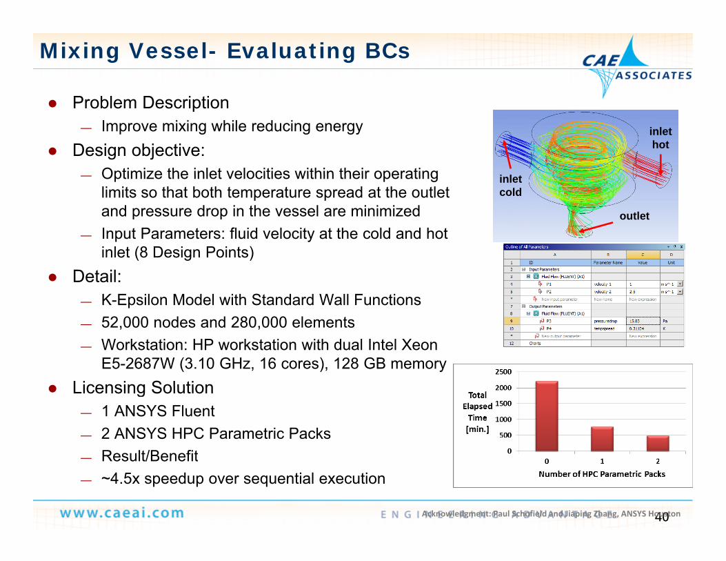
Problem Description Problem Description— Improve mixing while reducing energy
Design objective: Optimize the inlet velocities within their operating
inlet hot
— Optimize the inlet velocities within their operating limits so that both temperature spread at the outlet and pressure drop in the vessel are minimized
— Input Parameters: fluid velocity at the cold and hot
inlet cold
outlet
inlet (8 Design Points) Detail:
— K-Epsilon Model with Standard Wall Functions — 52,000 nodes and 280,000 elements— Workstation: HP workstation with dual Intel Xeon
E5-2687W (3.10 GHz, 16 cores), 128 GB memory Licensing Solution Licensing Solution
— 1 ANSYS Fluent— 2 ANSYS HPC Parametric Packs
Result/Benefit
40
— Result/Benefit— ~4.5x speedup over sequential execution
Acknowledgment: Paul Schofield and Jiaping Zhang, ANSYS Houston
Fatigue Analysis of Shaft
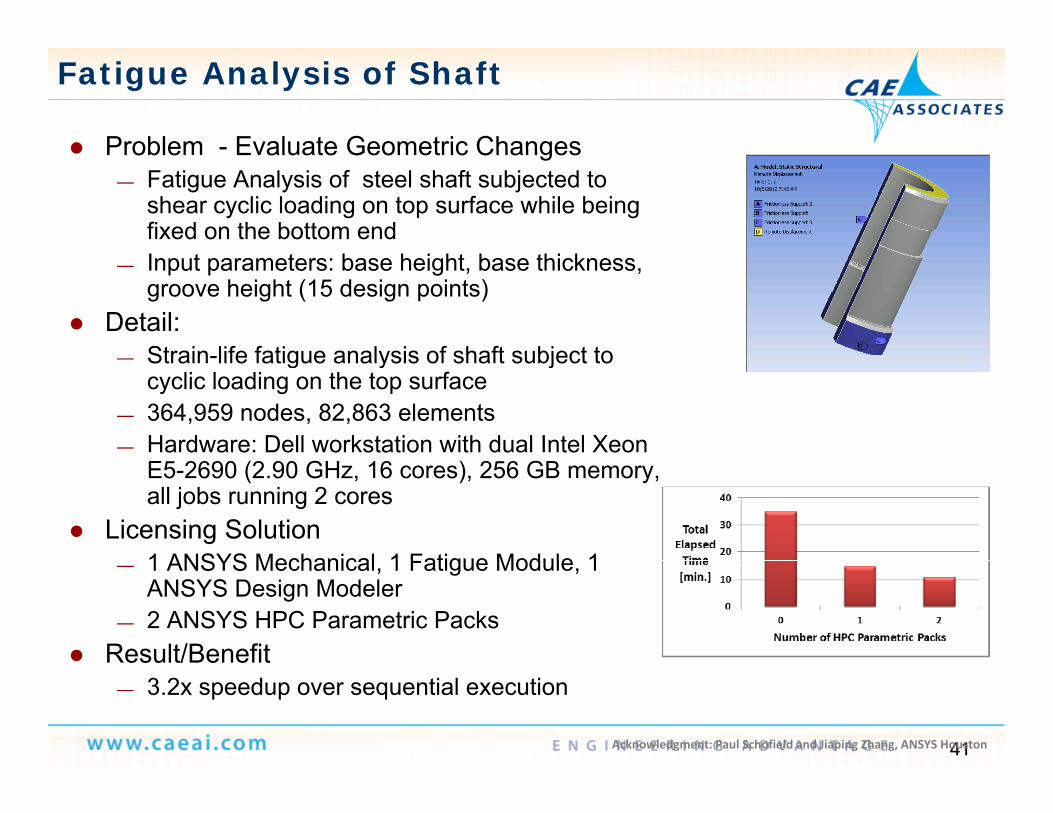
Problem - Evaluate Geometric Changes Problem Evaluate Geometric Changes— Fatigue Analysis of steel shaft subjected to
shear cyclic loading on top surface while being fixed on the bottom end
— Input parameters: base height, base thickness, groove height (15 design points)
Detail:Strain life fatigue analysis of shaft subject to— Strain-life fatigue analysis of shaft subject to cyclic loading on the top surface
— 364,959 nodes, 82,863 elements— Hardware: Dell workstation with dual Intel Xeon
E5-2690 (2.90 GHz, 16 cores), 256 GB memory, all jobs running 2 cores
Licensing Solution1 ANSYS Mechanical 1 Fatigue Module 1— 1 ANSYS Mechanical, 1 Fatigue Module, 1 ANSYS Design Modeler
— 2 ANSYS HPC Parametric Packs Result/Benefit
41
— 3.2x speedup over sequential execution
Acknowledgment: Paul Schofield and Jiaping Zhang, ANSYS Houston

Response Spectrum of Pressure Vessel
Problem – Evaluate Geometric Changes Problem Evaluate Geometric Changes— Pressure Vessel subjected to high internal
pressure and subjected to acceleration in supports during earthquake
— Input parameters: vessel thickness, vessel radius, vessel Height (16 design points)
Detail:“Static Structural” + ”Modal Analysis” +— Static Structural + Modal Analysis + ”Response Spectrum”
— 62,439 nodes, 150,169 elements— Hardware: Dell workstation with dual Intel
Xeon E5-2690 (2.90 GHz, 16 cores), 256 GB memory, all jobs running 2 cores
Licensing Solution1 ANSYS Mechanical 1 ANSYS— 1 ANSYS Mechanical, 1 ANSYS DesignModeler
— 2 ANSYS HPC Parametric Packs Result/Benefit
42
— ~3x speedup over sequential execution
Acknowledgment: Paul Schofield and Jiaping Zhang, ANSYS Houston

Intake Manifold Fluid Analysis
Problem Description – Optimize Geometry Problem Description Optimize Geometry— Non-homogenous air flow in intake
manifold through the 4 outlets Design objectives:
— Equal fresh and exhaust gas mass flow Initial— Equal fresh and exhaust gas mass flow
distribution to each cylinder— To minimize the overall pressure drop— Input Parameters: radii of 3 fillets near inlet
(16 design points) ( g p ) Detail:
• Steady state pressure based solver, realizable k-epsilon model
• 57,790 nodes, 208,740 elements• Hardware: Dell workstation with dual Intel
Xeon E5-2690 (2.90 GHz, 16 cores), 256 GB memory
Licensing Solution1 ANSYS CFX 1 ANSYS D i M d l
Optimized
— 1 ANSYS CFX, 1 ANSYS DesignModeler— 2 ANSYS HPC Parametric Packs
Result/Benefit— ~2.2x speedup over sequential execution
43Acknowledgment: Laurent Gerboud, ANSYS France

Thank You!
CAE Associates Inc. and ANSYS Inc. Proprietary© 2013 CAE Associates Inc. and ANSYS Inc. All rights reserved.