Abaqus Technology Brief Optimization in the Vibro-Acoustic Design of Hearing Instruments
Upload
cec-demilleCategory
view
30download
0
CAE Technologies for Efficient Vibro-Acoustic Vehicle Design Modification and Optimization
Stijn Donders, Luc Hermans, Edith Nauwelaerts, Shinnosuke Chojin LMS International Interleuvenlaan 68, B 3001, Leuven, Belgium email: [email protected] Bert Pluymers, Wim Desmet K.U.Leuven, Department Mechanical Engineering Celestijnenlaan 300 B, B-3001, Heverlee, Belgium
Abstract In automotive industry, Computer-Aided Engineering (CAE) methods are increasingly used to predict the various functional performance attributes (noise and vibration, crashworthiness, ...) and adapt the design based on the outcome of virtual simulations, such as numerical Finite Element (FE) models. This reduces the need for expensive physical prototypes, so that design cost and time-to-market can be reduced. The last step is still the final validation on a single physical prototype. If issues are still detected in this late stage, CAE techniques are very useful for efficient diagnosis and refinement engineering, to derive countermeasures and perform optimization. At present, the Finite Element Method (FEM) has become the dominant method for modal analysis and interior acoustics in the low and medium frequency range. For accurate predictions up to higher frequency, large FE model sizes are required, which limits the number of design iterations in a given time. Furthermore, at increasing frequency, the effect of uncertainty and variability (in geometric dimensions, material properties ....) becomes ever more important, so that for accurate performance (range) predictions, one has to include their effect in the modeling & simulation process. Many non-deterministic methods are based on using a deterministic “core” method to assess the effect of uncertainty and variability on the vehicle response. Methods for faster deterministic design iterations are useful to address both these issues, since they enable the evaluation of more design variants / a larger-scale optimization / a more extensive uncertainty assessment in a given time. This paper reports on two methodologies for efficient vibro-acoustic design, namely Wave-Based Substructuring (WBS) for efficient local re-design and Modal Modification for fast predictions of the effect of panel thickness and damping variations. Finally, the latter approach is used to speed up a non-deterministic analysis using the Fuzzy Finite Element approach, aimed at assessing the effect of panel uncertainty on the NVH response.
1 Introduction
1.1 The Automotive Design Process
Driving factors in modern automotive product development include the steadily increasing customer demands and competitive nature of the market. Automotive design engineers face the challenging but complex problem of meeting ever expanding but often conflicting design criteria and legislations, defined on various functional performance attributes such as strength and stiffness, emitted noise and vibration levels, crashworthiness, safety and ecological impact. Innovative designs must be achieved and brought to market before a competitor does. Better products must be launched on a shorter time frame and at lower cost [1]. Physical prototype phases must be eliminated, and product decisions must be taken earlier in the design process [2][3].
4127

A first major breakthrough has been the introduction of a fully digital design environment. Since the 1970s, Computer-Aided Design (CAD) has replaced the traditional drawing departments. CAD covers the “form-and-fit” stages of the automotive design process in a virtual design space. CAD is mainly used for detailed engineering of 2D drawings and/or 3D models of physical components. This requires a complete and detailed set of data, so that all surfaces, curvatures, flanges and tolerances can be accurately modeled. The virtual CAD designs are directly linked to the manufacturing process (numerically controlled machines, robots, ...), which has enabled a Computer-Aided Manufacturing (CAM) process. The second major breakthrough has been the emergence of Computer-Aided Engineering (CAE), which started in the 1960s with the first Finite Element (FE) solvers [4][5]. Nowadays, CAE methods are used more and more to predict the various functional performance attributes and adapt the design based on the outcome of the virtual simulations has been a huge improvement with the traditional “Test, Analyze & Fix” approach, in which physical prototypes were used to assess the performance [6]. At that late stage in the development, many development gates have been passed, manufacturing tools are being created and the main design decisions are already frozen, so that emerging problems can only be solved in a costly, suboptimal way. Three phases are distinguished in the vehicle development process, see Figure 1:
• Concept phase (before detailed CAD data becomes available).
• Detailed Engineering phase (concurrent with CAD design).
• Refinement Engineering phase (after freezing the CAD design).
Figure 1: Analysis Leads Design: By performing CAE simulations earlier,
the vehicle development phase can be shortened.
Nowadays, automotive OEMs (i.e. Original Equipment Manufacturers) aim at a “Design Right First Time” process [7][8], in which only a single prototype is manufactured to validate the design before the start of production. The only way to achieve this is to frontload the development process with functional performance engineering (FPE) - to get engineering problems solved as early as possible in the design cycle, and this at lower costs. For this purpose, a simulation-based design process must be achieved, in which simulation is the primary means of design evaluation and verification [3]. To achieve this, particular bottlenecks must be overcome in each phase.
4128 PROCEEDINGS OF ISMA2008

• CAE in the Concept Phase: This is the phase before detailed CAD data for the new vehicle has become available. The major challenge is to achieve an “Analysis Leads Design” process, in which an upfront engineering CAE analysis phase essentially precedes the detailed (geometrical) CAD design and in which CAE supports concept analysis to define the design requirements in order to meet the functional performance targets. This is a challenge, since almost all commercial CAE packages use numerical models based on detailed CAD models of the different components. One must therefore rely on predecessor data or engineering expertise to define simulation models. As illustrated in Figure 1 improved concept CAE predictions help improving the initial CAD design, hence contribute to shortening the design cycle.
• CAE in Detailed Engineering: In this phase, the component CAD models are created, and assembled into the vehicle body and other subassemblies, and finally the full vehicle model. The trend of mass customization forces engineers to design and assess a much higher number of design variants on a lower number of platforms. In addition, after a CAD design change, updated CAE models must be obtained quickly to allow assessing the effect of the design change on the various functional performance attributes. The focus in this phase is thus to perform fast design and simulation iterations. This is not straightforward because of the historic mismatch between CAD models and CAE models (in terms of descriptions, purpose of modeling, ...). Automatic meshing and assembly techniques are being developed to reduce manual operations and hence help bridging the CAD-to-CAE gap. Domain decomposition and component mode synthesis (CMS) methods are being used to limit the solution time for each variant.
• CAE in Refinement Engineering: This design validation and optimization phase has historically been the first playground of CAE methods. In this phase, the CAD design has been fixed and the first physical test results become available. CAE is used to efficiently build component, subsystem and full-vehicle models, through dedicated re-use of test data into the CAE process (“hybrid test-CAE approach”), and through supporting this process with correct, attribute-adapted loading conditions and procedures. CAE is used to investigate the issues identified in testing, and to evaluate alternatives towards solving these issues.
1.2 Focus and Outline of the paper
The vehicle functional performance attribute of interest in this paper is Noise, Vibration and Harshness (NVH). The current trends in automotive NVH design are firstly the increased role of virtual prototypes to drastically shorten design cycles and reduce development costs, while quality is not compromized; secondly, the mass customization (a higher number of variants is developed on a lower number of platforms. Many new vehicles brought to market are actually enhancements or incremental developments of legacy vehicles) and finally the fact that NVH gains importance w.r.t. other performance attributes. Customers become more pro-active towards the OEMs when it comes to the NVH performance, fuel economy pressures cars to become lighter, which has the result that NVH issues become more apparent and critical. Finally, noise pollution has become an important subject to EC legislation, since it is one of the environmental pressures that most closely affects the EU citizens, as confirmed by public surveys on overall nuisance and health problems. In the automotive NVH simulation process, a number of challenges can be distinguished. Firstly, the requirement for accurate predictions up to the medium frequency range. This refers to bridging the mid-frequency gap [9][15] between element-based methods and probabilistic Statistical Energy Analysis methods, to assessing the effect of uncertainty and variability on the vehicle response (which becomes more important at higher frequency) and to the accurate modeling of local structural models (connectors, trim, damping, ...) up to higher frequencies (which is more difficult at increasing frequency). The second challenge is to make NVH predictions become available earlier in the design process, to allow improving the quality of the initial design, and to increase the feasibility to balance possibly conflicting performance attributes (e.g. NVH, fuel economy and crash/safety) [10]. The final challenge is that faster design iterations are needed (to allow the evaluation of more variants / enable a larger-scale optimization / enable a more extensive uncertainty assessment in a given time). By focusing on CAE technologies for efficient
VEHICLE NOISE AND VIBRATION (NVH) 4129
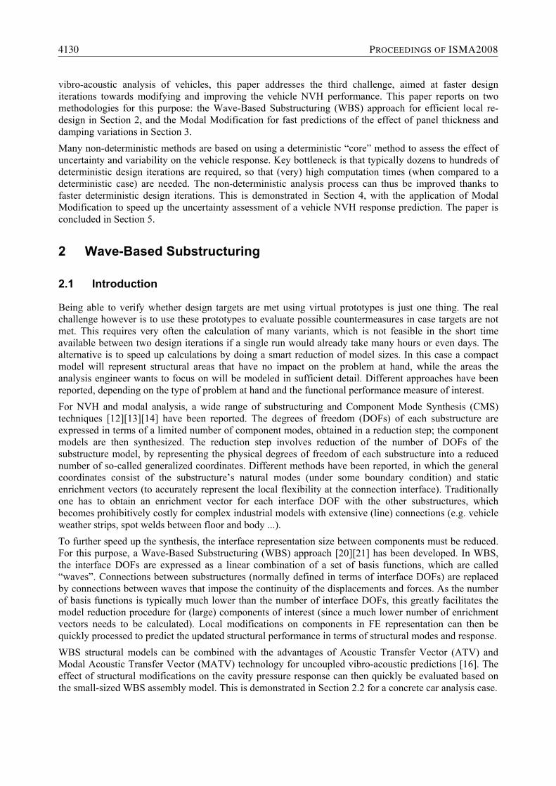
vibro-acoustic analysis of vehicles, this paper addresses the third challenge, aimed at faster design iterations towards modifying and improving the vehicle NVH performance. This paper reports on two methodologies for this purpose: the Wave-Based Substructuring (WBS) approach for efficient local re-design in Section 2, and the Modal Modification for fast predictions of the effect of panel thickness and damping variations in Section 3. Many non-deterministic methods are based on using a deterministic “core” method to assess the effect of uncertainty and variability on the vehicle response. Key bottleneck is that typically dozens to hundreds of deterministic design iterations are required, so that (very) high computation times (when compared to a deterministic case) are needed. The non-deterministic analysis process can thus be improved thanks to faster deterministic design iterations. This is demonstrated in Section 4, with the application of Modal Modification to speed up the uncertainty assessment of a vehicle NVH response prediction. The paper is concluded in Section 5.
2 Wave-Based Substructuring
2.1 Introduction
Being able to verify whether design targets are met using virtual prototypes is just one thing. The real challenge however is to use these prototypes to evaluate possible countermeasures in case targets are not met. This requires very often the calculation of many variants, which is not feasible in the short time available between two design iterations if a single run would already take many hours or even days. The alternative is to speed up calculations by doing a smart reduction of model sizes. In this case a compact model will represent structural areas that have no impact on the problem at hand, while the areas the analysis engineer wants to focus on will be modeled in sufficient detail. Different approaches have been reported, depending on the type of problem at hand and the functional performance measure of interest. For NVH and modal analysis, a wide range of substructuring and Component Mode Synthesis (CMS) techniques [12][13][14] have been reported. The degrees of freedom (DOFs) of each substructure are expressed in terms of a limited number of component modes, obtained in a reduction step; the component models are then synthesized. The reduction step involves reduction of the number of DOFs of the substructure model, by representing the physical degrees of freedom of each substructure into a reduced number of so-called generalized coordinates. Different methods have been reported, in which the general coordinates consist of the substructure’s natural modes (under some boundary condition) and static enrichment vectors (to accurately represent the local flexibility at the connection interface). Traditionally one has to obtain an enrichment vector for each interface DOF with the other substructures, which becomes prohibitively costly for complex industrial models with extensive (line) connections (e.g. vehicle weather strips, spot welds between floor and body ...). To further speed up the synthesis, the interface representation size between components must be reduced. For this purpose, a Wave-Based Substructuring (WBS) approach [20][21] has been developed. In WBS, the interface DOFs are expressed as a linear combination of a set of basis functions, which are called “waves”. Connections between substructures (normally defined in terms of interface DOFs) are replaced by connections between waves that impose the continuity of the displacements and forces. As the number of basis functions is typically much lower than the number of interface DOFs, this greatly facilitates the model reduction procedure for (large) components of interest (since a much lower number of enrichment vectors needs to be calculated). Local modifications on components in FE representation can then be quickly processed to predict the updated structural performance in terms of structural modes and response. WBS structural models can be combined with the advantages of Acoustic Transfer Vector (ATV) and Modal Acoustic Transfer Vector (MATV) technology for uncoupled vibro-acoustic predictions [16]. The effect of structural modifications on the cavity pressure response can then quickly be evaluated based on the small-sized WBS assembly model. This is demonstrated in Section 2.2 for a concrete car analysis case.
4130 PROCEEDINGS OF ISMA2008

2.2 Application Case: Bead Optimization on a Concrete Car
2.2.1 Case Setup
Bead optimization is a class of structural optimization in which the nodal positions of a shell FE model are used as design parameters. Bead optimization typically aims at stiffening a local panel modal displacement shape in order to reduce the vibro-acoustic radiation. A parametric bead optimization procedure for a vehicle spare wheel panel has been presented in [19]. A number of beads is defined, for which several parameters are varied (depth, width, orientation) with the aim to reduce the radiated noise inside the vehicle cavity. A bead optimization application and validation case has been worked out for a Concrete Car model [15], a simplified car cavity with the dimensions of a typical station wagon car cabin. The structure and its inner dimensions are shown in Figure 2.
Figure 2: Concrete Car structure: photo with characteristic dimensions.
The Concrete Car walls have a thickness of 10 cm and are made of concrete, so that the acoustic boundary conditions are well defined, in that the walls can be considered as acoustically rigid. The total weight of the structure is about 4 tons. A vibro-acoustic model has been made with the same geometry as the Concrete Car structure in Figure 2.
• The structure model is shown in Figure 3 (left); it has been made of steel with a shell thickness of 10mm, and it consists of a refined spare wheel panel (3.203 nodes, 3.166 quad elements) and the remainder of the concrete car (12.875 nodes, 12.787 quad elements). The spare wheel panel is a part of the vehicle floor panel, located at the rear of the Concrete Car model. An enlarged view of the spare wheel panel is shown in Figure 4 (left). The vertical direction corresponds to the z-axis. The y-axis is in the longitudinal direction, and the x-axis is in the transversal direction of the vehicle.
• The two structural components have been assembled with 72 rigid connections between coincident nodes; i.e. there are 432 junction DOFs. On the structural model, the locations of 4 wheels have been defined; at the wheel center nodes, all DOFs are constrained except the rotation around the wheel axis (rx, i.e. the rotation around the global x-axis).
• The vibro-acoustic cavity is shown in Figure 3 (right); the cavity is filled with air, and modeled with 7.136 hexa fluid elements (8.364 nodes). A microphone is placed in the cavity near the virtual driver ear position. A vibro-acoustic forced response case has been defined for the concrete car model. The Noise Transfer Function (NTF) of interest is the pressure over force NTF resulting from a unit-magnitude moment input at DOF ry (i.e. the rotation around the global y-axis) at the concrete car engine mount, in the range [0, 100]Hz. A modal-based forced response strategy is used, consisting of calculating first the structural modes, followed by a forced response in the modal domain [11].
VEHICLE NOISE AND VIBRATION (NVH) 4131

Figure 3: Concrete Car: the structural FE model (left) consists of the spare wheel panel and the remainder. Inside the structure, a vibro-acoustic air cavity FE model is located (right).
For efficient structural modifications, a WBS-reduced structural assembly model has been created, which contains the FE model of the spare wheel panel, and which contains a reduced modal model of the remainder of the structure (with as physical DOFs only the force input node and the wave participation factors). Modal damping of 2% has been applied to all modes (i.e. of the structure and the acoustic cavity). To make a small-sized WBS assembly model up to 100Hz, the waves have been calculated up to 150Hz (yielding 59 waves). The modes of the remainder reduction case have also been calculated up to 150Hz. For the WBS assembly connection definition, only 59 wave DOFs are required (instead of 432 physical junction DOFs), which results in a benefit in the reduction procedure and furthermore reduces the size of the WBS-reduced assembly model. Accurate structural analysis predictions are obtained [21]: when compared with full FE results, the maximum relative eigenfrequency difference is less than 1.4 · 10−3 for all 75 modes up to 150Hz. The average value of the MAC diagonal is 0.998 for the 75 modes up to 150Hz. In Table 1, the CPU times are compared for analysis cases of interest; it can be seen that WBS enables fast design iterations. All calculations have been performed on an Intel Pentium D computer system (3GHz, 3.5GB RAM) running Windows XP, with MSC.Nastran [29] version 2004.0.0 as FE solver, using LMS Virtual.Lab [32] for pre-/postprocessing, intermediate calculations, MAC and vibro-acoustic calculations. Table 1: Concrete Car: CPU times for full FE and WBS-reduced assembly case (spare wheel panel in FE representation, WBS-reduced modal model of remainder) and for Remainder reduction case.
Analysis Case CPU Time
Full FE analysis 95.6s
WBS Reduction for the Remainder 92.7s
WBS-reduced Assembly 1.7s
For the acoustic cavity, the modes up to 300Hz are calculated; there are 34 modes in this range. Modal damping of 2% has been applied to all acoustic modes. From the damped modal solution, the Acoustic Transfer Vectors (ATV) matrix is calculated [16]. The pressure p at the acoustic microphone position can be expressed according to Eq. (3.1), which in Eq. (1) has been partitioned using an MATV approach into
• a contribution ppan(ω) of the acoustic radiation from the spare wheel panel (in FE representation);
• a contribution prem(ω) of the reduced remainder of the concrete car
{ } { } { } { } { } { }panTpanrem
Tremn
T MRSPMATVMRSPMATVvATVp ∑∑∑ +== (1)
4132 PROCEEDINGS OF ISMA2008

The remainder MATV matrix is calculated by expressing the ATVs from the remainder part in terms of the remainder reduction modes. This MATV matrix does not change, since the remainder reduction modes are constant when the spare wheel panel is locally modified. To obtain the pressure contribution of the remainder part in assembly conditions, the remainder MATVs are multiplied with the modal participation factors (MPFs) of the remainder reduction mode set; new values for these MPFs are obtained from the WBS-reduced assembly calculation. The spare wheel panel MATV matrix is calculated by expressing the ATVs from the spare wheel panel part in terms of the WBS-reduced assembly modes. For each structural modification on the spare wheel panel, this MATV matrix is re-calculated. The pressure contribution of the spare wheel panel in assembly conditions is obtained by multiplying the spare wheel panel MATV matrix with the modal participation factors of the WBS-reduced assembly modes.
2.2.2 Bead Optimization
A bead optimization analysis case has been worked out on the spare wheel panel of the concrete car. Bead optimization can be used to minimize static compliance or to maximize/minimize a selection of eigenfrequencies for a plate or shell structure by introducing bead patterns in the structure. In this paper, the bead optimization software program TOSCA 6.1 (from FE Design) has been used. The optimization is based on a design rule, which uses the value of the bending stress tensor and a bead filtering technique depending upon the bead width [17] to result in physical bead patterns [18]. A fully automated bead optimization tree has been set-up targeting the optimization of the acoustic pressure inside a concrete car model (i.e. a simplified full vehicle system) allowing modifications to be performed on the bead pattern in an identified spare-wheel panel component. The process is steered by the Optimus [31] software and involves communication between the bead optimizer software TOSCA [30], MSC/Nastran as structural FE solver [29] and LMS Virtual.Lab [32] to apply the wave-based substructuring approach and to calculate the vibro-acoustic pressure results inside the cavity. For the vibro-acoustic Concrete Car simulation model, first the nominal mode shapes have been investigated. Three local mode shapes at the spare wheel panel have been selected; bead optimization has been performed to increase the eigenfrequency of these local mode shapes. The rationale is that when the eigenfrequency values are increased, the vibration amplitudes will decrease. For more details, see [21]. Figure 4 shows the original spare wheel panel (left) and the panel with optimized bead pattern (right).
Figure 4: Bead Optimization of spare wheel panel of the concrete car: the original spare wheel panel (left) is compared with the spare wheel panel with an optimized bead pattern (right).
Figure 5 shows the Noise Transfer Function (NTF) of interest (moment input at the engine mount DOF ry to microphone pressure value at the driver ear position) before and after bead optimization. It can be seen that the bead optimization has resulted in a lower peak value of the acoustic pressure at 52Hz (minus 12dB). As a result of the increased eigenfrequency values of the local mode shapes, the peak amplitude is shifted to 55Hz, where it however reaches a much lower amplitude level (minus 8dB) than the original maximum peak at 52Hz.
VEHICLE NOISE AND VIBRATION (NVH) 4133

The results obtained on the concrete car model illustrate the potential of the considered integrated optimization approach. In general, WBS can be used for efficient design modifications in view of reaching structural or vibro-acoustic performance targets. Especially in case of large interface size between the substructures, a common situation in vehicle industry (B-pillars, cowl top, roof or floor, ...), WBS offers a clear benefit for vehicle design modifications, by drastically improving the speed of component reduction processes and by improving the efficiency and accuracy of design iteration predictions when compared to conventional substructuring approaches [20][21].
Figure 5: Concrete Car: nominal pressure response (black, solid) and the WBS-reduced assembly model (black, dashed). The bead pattern of the spare wheel panel has been optimized based on the WBS-reduced assembly model (red/gray, dashed). A full FE validation run (red/gray, solid) is performed with the modified panel, which perfectly overlaps with the WBS-reduced prediction. Key result of bead optimization is that the acoustic peak response at 52Hz has been lowered.
3 Modal Modification
3.1 Outline of Method & Process
A modal modification methodology has been developed, to be used in the vehicle NVH refinement phase to evaluate effect of small modifications on vibro-acoustic targets [8]. It is a modal-based sensitivity and optimization approach, which is generally used in the refinement phase to evaluate the effect of small modifications on vibro-acoustic targets. The industrial process for a full vehicle body is as follows:
• The nominal modes are calculated in a modal analysis of the full vehicle (body).
• A weak spot detection is performed to indicate the most sensitive areas for modifications. A set of nominal modifications is defined, for parameters as thickness, damping, ... .
• After selection, each nominal modification is projected in the modal domain and its effect on the response can be quickly evaluated.
• As a last step, scaling factors are assigned to each modification, and used as design parameters in an optimization process, aiming e.g. to improve the NVH performance for different load cases (road noise, booming noise) or directly on the frequency response function between input points and target points or microphones.
4134 PROCEEDINGS OF ISMA2008
The modal modification approach is an efficient alternative for full FE analysis or superelement analysis. A transformation matrix is used to project the modification corresponding to a parameter change in the component model space. The impact of each modification can be assembled in the system model, and efficiently evaluated in this highly reduced system model space. The underlying assumption is that the transformation matrix of the modified system spans the same space as the one of the unmodified system. The component modes of the modified component are written as a combination of the unmodified ones. This is indeed a reasonable assumption for small modifications. When modifications become too large, one can no longer describe the eigenmodes by a linear combination of the nominal eigenmodes, so that a new FE analysis may become necessary. The Modal Modification approach is available in LMS Virtual.Lab [32], using the MSC/Nastran FE solver (for which dedicated DMAP programming sequences have been written) to execute the process steps:
1. Perform a modal analysis for the full FE model 2. Calculate the matrices ∆K and ∆M for selected panels (i.e. the stiffness & mass matrices
representing a user-defined modification of the panel property, e.g. 10% thickness change) 3. Modal modification calculation (in which scaled panel matrices ∆K and ∆M are added to the
nominal mode set, and the effect of the modification is calculated). In a design sensitivity analysis procedure for weak spot analysis, one can use the scaling factors to the panel matrices directly to identify the most sensitive panels, e.g. panel thicknesses. This allows efficiently reducing the design space. In a design optimization sequence, it is then recommended to parameterize directly the thickness of these panels (re-calculate the matrices and efficiently evaluate its effects). Since there’s no direct relation between a scaled matrix and a physical property modification, it is not straightforward to interpret an optimum set of scaling factors.
3.2 Application Case: Panel Thickness Modification for a vehicle BIW
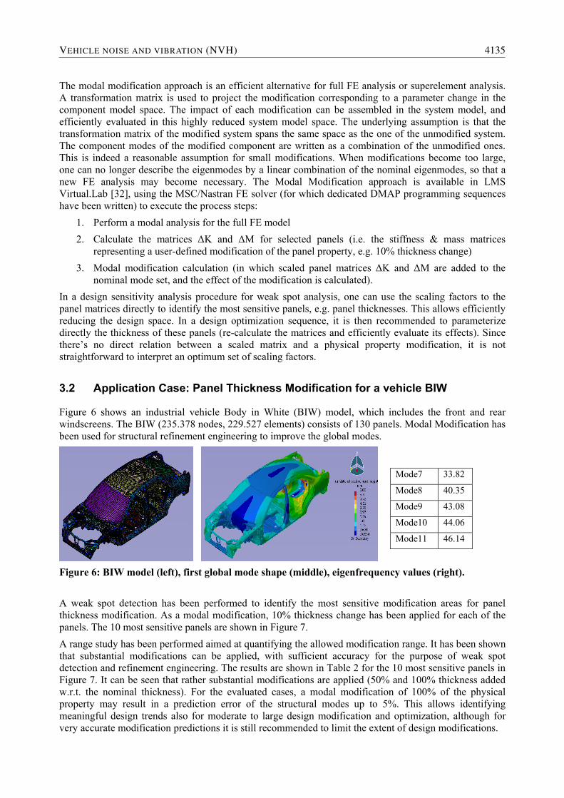
Figure 6 shows an industrial vehicle Body in White (BIW) model, which includes the front and rear windscreens. The BIW (235.378 nodes, 229.527 elements) consists of 130 panels. Modal Modification has been used for structural refinement engineering to improve the global modes.
Figure 6: BIW model (left), first global mode shape (middle), eigenfrequency values (right).
A weak spot detection has been performed to identify the most sensitive modification areas for panel thickness modification. As a modal modification, 10% thickness change has been applied for each of the panels. The 10 most sensitive panels are shown in Figure 7. A range study has been performed aimed at quantifying the allowed modification range. It has been shown that substantial modifications can be applied, with sufficient accuracy for the purpose of weak spot detection and refinement engineering. The results are shown in Table 2 for the 10 most sensitive panels in Figure 7. It can be seen that rather substantial modifications are applied (50% and 100% thickness added w.r.t. the nominal thickness). For the evaluated cases, a modal modification of 100% of the physical property may result in a prediction error of the structural modes up to 5%. This allows identifying meaningful design trends also for moderate to large design modification and optimization, although for very accurate modification predictions it is still recommended to limit the extent of design modifications.
Mode7 33.82
Mode8 40.35
Mode9 43.08
Mode10 44.06
Mode11 46.14
VEHICLE NOISE AND VIBRATION (NVH) 4135
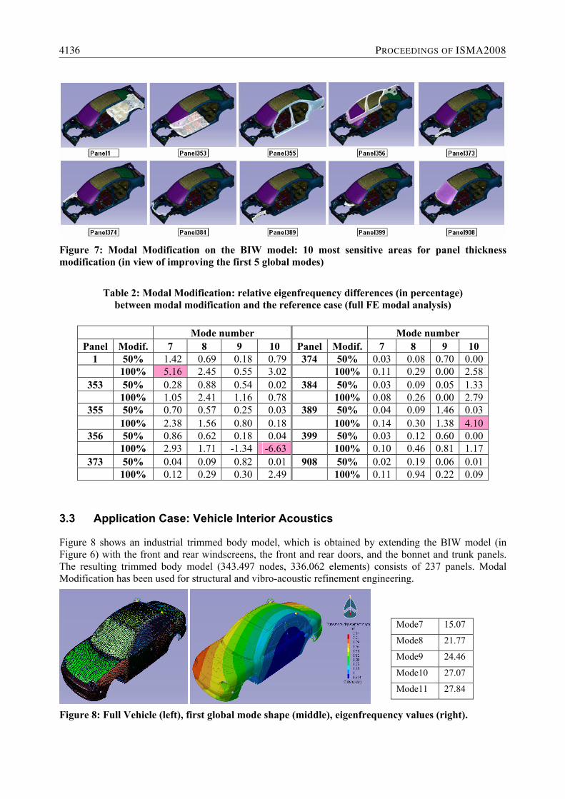
Figure 7: Modal Modification on the BIW model: 10 most sensitive areas for panel thickness modification (in view of improving the first 5 global modes)
Table 2: Modal Modification: relative eigenfrequency differences (in percentage) between modal modification and the reference case (full FE modal analysis)
3.3 Application Case: Vehicle Interior Acoustics
Figure 8 shows an industrial trimmed body model, which is obtained by extending the BIW model (in Figure 6) with the front and rear windscreens, the front and rear doors, and the bonnet and trunk panels. The resulting trimmed body model (343.497 nodes, 336.062 elements) consists of 237 panels. Modal Modification has been used for structural and vibro-acoustic refinement engineering.
Figure 8: Full Vehicle (left), first global mode shape (middle), eigenfrequency values (right).
Mode number Mode number Panel Modif. 7 8 9 10 Panel Modif. 7 8 9 10
1 50% 1.42 0.69 0.18 0.79 374 50% 0.03 0.08 0.70 0.00 100% 5.16 2.45 0.55 3.02 100% 0.11 0.29 0.00 2.58
353 50% 0.28 0.88 0.54 0.02 384 50% 0.03 0.09 0.05 1.33 100% 1.05 2.41 1.16 0.78 100% 0.08 0.26 0.00 2.79
355 50% 0.70 0.57 0.25 0.03 389 50% 0.04 0.09 1.46 0.03 100% 2.38 1.56 0.80 0.18 100% 0.14 0.30 1.38 4.10
356 50% 0.86 0.62 0.18 0.04 399 50% 0.03 0.12 0.60 0.00 100% 2.93 1.71 -1.34 -6.63 100% 0.10 0.46 0.81 1.17
373 50% 0.04 0.09 0.82 0.01 908 50% 0.02 0.19 0.06 0.01 100% 0.12 0.29 0.30 2.49 100% 0.11 0.94 0.22 0.09
Mode7 15.07
Mode8 21.77
Mode9 24.46
Mode10 27.07
Mode11 27.84
4136 PROCEEDINGS OF ISMA2008

For vibro-acoustic response predictions, the structural modal modifications can be combined with the advantages of ATV and MATV technology for uncoupled vibro-acoustic predictions [16], in a similar process as described in Section 2.2. The effect of structural modifications on the cavity pressure response can then quickly be evaluated based on the efficient modal modifications. For the vehicle model in Figure 8, the vibro-acoustic objective function is the Body Noise Transfer Function (BNTF) between the vertical input on the engine head mount and the interior noise (driver ear position). The objective is to reduce the acoustic pressure in the range 80-85Hz. A sensitivity analysis has been performed on the largest 50 panels with respect to the improvement on the pressure curve; the 4 most sensitive panels are shown in Figure 9.
Figure 9: Modal Modification for Full Vehicle model: 4 most sensitive areas for panel thickness modification (in view of reducing the acoustic pressure in the range 80-85Hz).
Figure 10 shows the BNTF between the vertical input on the engine head mount and the interior noise (driver ear position) in the range 0-100Hz, for a modal modification of 30% on the shell thickness of the firewall (panel 352). This modification results in a reduction of the vibro-acoustic pressure close to 1dB in the range 80-85Hz as compared to the nominal pressure level. This modification is accurately predicted with the modal modification approach.
Figure 10: Modal Modification for Full Vehicle model: nominal pressure response (thin line); modified response predicted with modal modification (dashed) and in full FE validation (thick).
A quantification of the efficiency of the modal modification approach is given below. On an Intel Pentium4 2110 computer system (2.8GHz, 3GB RAM) running a Windows XP operating system), the following process times are obtained for the vibro-acoustic response calculation process (see Figure 11):
(A) Full FE calculation to obtain the global mode shapes: 18 hours (0-150 Hz, i.e. 321 modes) (B) Calculate ∆K and ∆M for selected panels: 3 min for each panel (C) Modal Modification calculation: 2.5 min (321modes) (D) FRF calculation: 15 sec (1-100Hz, step 1Hz) (E) MATV response calculation: 1.5 min (1-100Hz, step 0.5Hz)
VEHICLE NOISE AND VIBRATION (NVH) 4137

Figure 11: Modal Modification: process outline for Vibro-Acoustic Response Predictions.
It can be seen that a single nominal vibro-acoustic response prediction (A)+(D)+(E) requires 18 hours. Using modal modification, large calculation time savings are obtained:
• When using modifications on the panel thickness: (B)+(C)+(D)+(E) per panel = 7 min.
• When using modifications on the matrix scaling factors: (C)+(D)+E) per panel = 4 min.
4 Non-deterministic Analysis
4.1 Uncertain Response Calculation using the Transformation Method
In real-life structures, it is typically not possible to assign an exact value to all parameters. Two classes of non-determinism in parameter values are distinguished [22]. Variability refers to the variation inherent to the physical system or the environment under consideration, while uncertainty is a potential deficiency in any phase or activity of the modeling process that is due to lack of knowledge. Other definitions may be agreed upon, but the above definitions are used throughout this paper. The non-determinism affects the performance, so must be taken into account in the modeling process. Variability (material characteristics, manufacturing tolerances ...) can be handled with a probabilistic approach, while uncertainty (damping, boundary conditions ...) can be assessed with a possibilistic approach, e.g. fuzzy arithmetic. Often in an engineering practice (especially in an early design stage), one is not able to quantify an input parameter in a probabilistic framework (type of distribution, mean, variance ...). One can then use a possibilistic description (between a minimum and a maximum, not larger/smaller than ..., etc) of the non-determinism in the inputs. Fuzzy arithmetic can be used to quantify these possibilistic distributions and propagate the effect of the uncertainty on the system response, to obtain boundaries on this system response. This section first introduces fuzzy set theory, and then describes the Transformation Method, which is used to assess the effect of panel thickness uncertainty on a vehicle BIW response in Section 4.2.
In classical set theory, the elements of a set either belong to the set entirely (membership level µ=1), or do not belong to the set at all (µ=0). This principle is generalized in fuzzy set theory: a membership level µA(x)∈ [0,1] is assigned to all elements x, so that the elements can belong to the set A to a certain degree. Fuzzy numbers (see the example in Figure 12) can be used to quantify the input uncertainty. The shape of the membership function can be derived from expert knowledge or practical measurements. Typically the alpha-cut strategy [25] is used, to subdivide the fuzzy inputs into a number of intervals. These intervals are then further processed to obtain interval (envelopes) predictions on the output responses. Two specific recent implementation strategies found in literature are enabling efficient fuzzy finite element analyses,
4138 PROCEEDINGS OF ISMA2008

resulting in applicability on industrially sized models: the Hybrid Fuzzy Finite Element method and the Transformation Method.
The idea behind the Hybrid Fuzzy Finite Element method [26] is to remedy the excessive conservatism of classical interval arithmetic by using a combination of global optimization techniques and interval arithmetic. In the first part of the analysis, global optimization is applied to calculate the interval result at some intermediate step of the total algorithm. In the second part, the interval analysis is performed on these intermediate results using classical interval arithmetic rules [27][28].
Figure 12: Fuzzy number: example (Gaussian membership function, subdivided into 4 intervals).
Figure 13: Visualization of the Reduced TM in case there are 3 inputs and 5 interval levels. Each black dot is an evaluated parameter combination.
The second path towards a fuzzy FE method is based on Design of Experiments (DOE) methodology and conventional arithmetic. The Vertex Method [24] performs a full-factorial DOE on the input vertex of the fuzzy problem (the interval [a,b] at the lowest membership level in Figure 12). For n inputs, this means that all 2n parameter combinations are successively analysed in a conventional deterministic analysis run. The fuzzy output interval is then reconstructed from the deterministic results. The remaining members of the Transformation Method (TM) family are all extensions of the Vertex Method. For the Reduced TM [25], one first subdivides the inputs into intervals, and then applies a 2n Full Factorial DOE for each of the intervals. The method provides the exact results when the outputs are monotonic in the inputs; otherwise an error is introduced. Figure 13 visualizes an example DOE plan of the Reduced TM: it can be seen that all diagonals in the parameters space are evaluated. Alternative methods have been presented, such as the General TM [25] (which adds more points and is thus better capable to deal with non-monotonicity at the cost of a high increase in CPU time) and the Short TM [21] (which only evaluates samples along a single diagonal in the design space); this latter method is fast and sufficiently accurate to predict structural responses in case that input uncertainty has a monotonic effect on the outputs (eigenfrequency values, eigenvectors, displacements ...).
4.2 Application Case: Modal Modification for efficient uncertainty assessment
The Reduced TM [25] is a DOE-based approach, which uses a deterministic “core” method to assess the effect of uncertainty and variability on the vehicle response. Key bottleneck in the uncertainty assessment is thus the deterministic calculation time. Since typically dozens to hundreds of deterministic design iterations are required, one needs (very) high computation times (when compared to a deterministic case). In this section, it is demonstrated that the non-deterministic analysis process can be improved thanks to faster deterministic design iterations. That is, Modal Modification is used to speed up the uncertainty assessment that is calculated with the Reduced TM.
VEHICLE NOISE AND VIBRATION (NVH) 4139

The considered application case is the industrial vehicle Body in White (BIW) model in Figure 6. The uncertain response of interest is the FRF from engine mount (force +z) to the seat rail (displacement +z). Six uncertain parameters have been defined, namely the thickness of the 6 most sensitive panels (see Section 3.2). For each panel thickness, an independent uncertain parameter is introduced in the range [0, +50%] as compared to the nominal thickness. In general, the reduced TM requires 1 + m · 2n deterministic calculations. For the uncertain FRF analysis using the Reduced Transformation Method, m=5 levels of membership are defined for each fuzzy number. This means that the required number of calculations is given by 1 + 5 · 26 = 321. Modal Modification has been used as efficient core to calculate all of these deterministic calculations, which results in large savings in calculation times (as compared to using a full FE analysis for each of the deterministic calculations). The uncertain FRF response is shown in Figure 14.
Figure 14: BIW: uncertain FRF response (from engine mount to seat rail)
resulting from panel thickness uncertainty. The Modal Modification approach has been used to increase the efficiency of the uncertainty assessment.
5 Conclusions
In this paper, two CAE methodologies for efficient vibro-acoustic design modification have been covered. Firstly, it has been shown that the Wave-Based Substructuring (WBS) can be used for efficient local re-design of the structure, in view of improving the vibro-acoustic performance. Bead optimization is an example of local re-design in a vehicle development process; its value has been demonstrated on a concrete car model, for which the acoustic pressure response has been reduced. Secondly, the Modal Modification approach has been covered. This is a modal-based sensitivity and optimization approach, which is generally used in the refinement phase to evaluate the effect of small modifications on vibro-acoustic targets. It has been shown that this approach yields large calculation time savings for structural and vibro-acoustic response predictions. It allows identifying meaningful design trends also for moderate to large design modification and optimization, although for very accurate modification predictions it is still recommended to limit the extent of design modifications. Finally, it is recognized that many non-deterministic methods are based on using a deterministic “core” method to assess the effect of uncertainty and variability on the vehicle response. Key bottleneck is that
4140 PROCEEDINGS OF ISMA2008

typically dozens to hundreds of deterministic design iterations are required, so that (very) high computation times (when compared to a deterministic case) are needed. This can be alleviated when one uses a CAE methodology for efficient vibro-acoustic design modification to speed up the iterations. To demonstrate this the Modal Modification approach has been used to speed up an uncertainty assessment aimed at assessing the effect of panel uncertainty on the NVH response. The uncertainty analysis has been performed with the Reduced Transformation Method (a fuzzy arithmetic approach). In the analyses, the Modal Modifications have been used as fast deterministic “core” calculation (that otherwise would have to be calculated with a costly full FE analysis). This has led to substantial calculation time savings. In general, CAE technologies for efficient vibro-acoustic design modification and optimization are very important for the vehicle development process, since they enable faster design iterations, to allow the evaluation of more variants / enable a larger-scale optimization / enable a more extensive uncertainty assessment in a given calculation time (overnight, over the weekend, ...).
Acknowledgements
This paper highlights some of the research outcome of the project ‘Analysis Leads Design – Frontloading Digital Functional Performance Engineering’ (ALD). The research activity on efficient re-analysis techniques is being continued in the frame of the SBO research project “Fuzzy Finite Element Method” (Fuzzy FE). In this paper, it has indeed been demonstrated that Modal Modification can be used as efficient deterministic core calculation in a fuzzy FE analysis. IWT Vlaanderen is gratefully acknowledged for supporting both these projects. MMC is acknowledged for their participation to the research and development of Wave-Based Substructuring and Modal Modification. Finally, we kindly acknowledge Peter Clausen (FE Design GmbH) for his contribution to the research activity on bead optimization.
References
[1] H. Van der Auweraer, J. Leuridan, The New Paradigm of Testing in Todays Product Development Process, Proc. ISMA2004, Leuven, Belgium, Sept. 20-22, 2004, pp. 1151–1170.
[2] G. Wöhlke, E. Schiller, Digital Planning Validation in automotive industry, Computers in Industry, 56(4):393–405, 2005.
[3] M. Shephard, M. Beall, R. O’Bara, B. Webster, Toward simulation-based design, Finite Elements in Analysis and Design, 40(12):1575–1598, 2004.
[4] M. Turner, R. Clough, H. Martin, L. Topp, Stiffness and Deflection Analysis of Complex Structures, Journal of Aerospace Science, 23(9):805–823, 1956.
[5] O. Zienkiewicz, R. Taylor, J. Zhu, P. Nithiarasu, Finite Element Method - The three volume set, Butterworth-Heinemann, Boston, sixth edition, 2005.
[6] D. Roesems, A new methodology to support an optimized NVH engineering process, Sound and Vibration, 31(5):36–45, 1997.
[7] H. Shiozaki, Y. Kamada, S. Kurita, S. Goossens, J. Van Herbruggen, V. Cibrario, and L. Poppelaars, CAE based vehicle development to reduce development time, Proc. JSAE, Yokohama, Japan, 2005.
[8] R. Hadjit, M. Brughmans, H. Shiozaki, Application of Fast Body Optimization Procedures to Shorten Car Development Cycles, Proc. JSAE, Yokohama, Japan, 2005.
[9] W. Desmet, Mid-frequency vibro-acoustic modelling: challenges and potential solutions, Proc. ISMA 2002, pages 835–862, Leuven, Belgium, 2002.
[10] H. Van der Auweraer, S. Donders, R. Hadjit, M. Brughmans, P. Mas, J. Jans, New approaches enabling NVH analysis to lead design in body development, Proc. EIS NVH Symposium “New Technologies and Approaches in NVH”, Coventry, UK, November 3, 2005.
VEHICLE NOISE AND VIBRATION (NVH) 4141

[11] W. Heylen, S. Lammens, P. Sas, Modal Analysis Theory and Testing, Katholieke Universiteit Leuven, Departement Werktuigkunde, Leuven (1997).
[12] R.R. Craig Jr., Structural dynamics – an introduction to computer methods, Wiley, NY, (1981). [13] R.H. MacNeal, A hybrid method of component mode synthesis, Comput Struct 1 (1971), pp. 581-601. [14] L. Hermans, M. Brughmans, Enabling vibro-acoustic optimization in a superelement environment: a
case study, Proc. IMAC XVIII, San Antonio, TX, USA, (2000), pp. 1146-1152. [15] B. Pluymers, Wave Based Modelling Methods for Steady-State Vibro-Acoustics, PhD thesis,
K.U.Leuven, Department of Mechanical Engineering, Division PMA, Leuven, Belgium, June 2006. Available online: http://hdl.handle.net/1979/320.
[16] F. Gérard, M. Tournour, N. El Masri, L. Cremers, M. Felice, A. Selmane, Numerical Modeling of Engine Noise Radiation through the use of Acoustic Transfer Vectors - A Case Study, Proc. SAE 2001-01-1514, Traverse City, MI, USA, (2001).
[17] D. Emmrich, Entwicklung einer FEM-basierten Methode zur Gesaltung von Sicken für biegebeanspruchte Leitsttzstrukturen im Konstruktionsprozess, Forschungsberichte, band 13, Institut für Produktentwicklung, Karlsruhe, Germany, 2004.
[18] P. Clausen, C. Pedersen, Non-parametric Large Scale Structural Optimization for Industrial Applications, Proc. ECCM-2006, Lisbon, Portugal, June 5-8, 2006.
[19] S. Marburg, H.-J. Hardtke, Investigation and Optimization of a Spare Wheel Well to Reduce Vehicle Interior Noise, Journal of Computational Acoustics, 11(3):425–449, 2003.
[20] S. Donders, R. Hadjit, L. Hermans, M. Brughmans, W. Desmet, A Wave-Based Substructuring Approach for Fast Modification Predictions and Industrial Vehicle Optimization, Proc. ISMA 2006, pp. 1901-1912, September 18-20, 2006, Leuven, Belgium.
[21] S. Donders, Computer-aided engineering methodologies for robust automotive NVH design, PhD thesis, K.U.Leuven, Department of Mechanical Engineering, Division PMA, Leuven, Belgium, February 2008. Available online: http://hdl.handle.net/1979/1698.
[22] L.A. Zadeh, Fuzzy sets, Information and Control, 8:338-353, 1965. [23] W. Oberkampf et al., Variability, Uncertainty & Error in Computational Simulation, AIAA/ASME
Joint Thermophysics and Heat Transfer Conference, ASME-HTD-Vol.357-2, pp. 259-272, 1998. [24] W. Dong, H.C. Shah, Vertex Method for Computing Functions of Fuzzy Variables, Fuzzy Sets and
Systems 24, pp. 65-78, 1987. [25] M. Hanss, The Transformation Method for the simulation and analysis of systems with uncertain
parameters, Fuzzy Sets and Systems, 130(3):277-289, 2002. [26] D. Moens, A non-probabilistic finite element approach for structural dynamic analysis with
uncertain parameters, PhD thesis, K.U.Leuven, Department of Mechanical Engineering, Division PMA, Leuven, Belgium, Oct. 2002.
[27] D. Moens, D. Vandepitte, A fuzzy finite element procedure for the calculation of uncertain frequency response functions of damped structures: Part 1 - Procedure, Journal of Sound and Vibration, 288(3):431–462, 2005.
[28] H. De Gersem, D. Moens, W. Desmet, D. Vandepitte, A fuzzy finite element procedure for the calculation of uncertain frequency response functions of damped structures: Part 2 - Numerical case studies, Journal of Sound and Vibration, 288(3):463–486, 2005.
[29] MSC, MSC.Nastran 2004, (2004). [30] FE Design, TOSCA 6.1, 2007. [31] Noesis Solutions, OPTIMUS Rev. 5.3 SP1, March 2008. [32] LMS International, LMS Virtual.Lab Rev. 7B-SL1, March 2008.
4142 PROCEEDINGS OF ISMA2008