CAE Support to the Designn of Parts made ofn of Parts made ...
1
D i & CAE G E Design & CAE Group Europe Design & CAE Group Europe Design & CAE Group Europe CAE Support to the Design CAE Support to the Design CAE Support to the Design (*Glass Fiber- Reinfo M Nutini 1 M Vitali 1 M C Ferrari 1 C Garc M.Nutini , M.Vitali , M.C.Ferrari , C.Garc 1 Basell Poliolefine italia srl; 2 Basell Poliolefinas Co Española 1 Basell Poliolefine italia srl; 2 Basell Poliolefinas Co. Española Abstract Abstract Abstract Abstract Gl fib if d l l (GF PP) t il l i tl d i i l i t ti t t l Glass fiber reinforced polypropylene (GF-PP) materials are replacing metal and engineering polymers in automotive structural applications Like all glass fiber reinforced thermoplastics GF PP products can show anisotropy caused by fiber orientation induced applications. Like all glass fiber reinforced thermoplastics, GF-PP products can show anisotropy caused by fiber orientation induced by the injection process. Taking into account fiber orientation in the simulations allows the designers to improve the accuracy of the by the injection process. Taking into account fiber orientation in the simulations allows the designers to improve the accuracy of the analyses and can avoid some arbitrary choices needed when using an isotropic material law . Two methods are here presented: - A first approach is based on micromechanical modeling through homogenization methods available from commercial software (Di i t®) Thi ll li f th t t l l i ith th fib i t ti hi h i bt i d f th i l (Digimat®). This allows coupling of the structural analysis with the fiber orientation, which is obtained from the numerical simulation of the injection process simulation of the injection process. - The authors developed a simplified approach where the presence of the reinforcing glass fibers is kept into account using an The authors developed a simplified approach where the presence of the reinforcing glass fibers is kept into account using an orthotropic material law . Here the reference directions are given by the material flow direction, which can be obtained from a moldfilling analysis. Both the approaches request very simple tensile tests for the determination of the model parameters. I th d i h th hi f ith h ill d d th bl t b t di d th d ti i il bl In the design phase, the choice of either approach will depend on the problem to be studied, on the resources and timing available, and on the desired accuracy and on the desired accuracy . Material Material Structure Structure Material Material Structure Structure I lti h t il h SGF PP th h i l ti d d th tit ti ti f th b t il d In a multi-phase material such as SGF-PP, the mechanical properties depend on the constitutive properties of the base materials and the composite morphology i e the weight fraction length diameter and orientation of the fibers These properties are induced by the composite morphology, i.e., the weight fraction, length, diameter and orientation of the fibers. These properties are induced by material processing as in the case of injection molding Here a classical skin-core structure is observed and depending on the material processing, as in the case of injection molding. Here, a classical skin core structure is observed and, depending on the thickness, can be more or less pronounced. Along the material thickness, a central portion, or “core”, is characterized by fiber orientations perpendicular to the flow, and a lateral portion is characterized by fiber orientations parallel to the flow. CT image of GF-PP sample Source: test performed Source: test performed for LyondellBasell by Fraunhofer ITWM Method Method based on Micromechanical Modeling based on Micromechanical Modeling Method Method based on Micromechanical Modeling based on Micromechanical Modeling Two-scale models are used with a macro-scale associated to the part and a micro-scale associated to the material microstructure. The transition between the two scales can be accomplished through a homogenization process. In this case, fiber content, geometry and fiber distribution, together with the matrix properties, are the required parameters. Fundamental items of this approach are then: Fundamental items of this approach are then: P di ti f Fib i t ti t f d t th t t l Prediction of Fiber orientation, transferred to the structural mesh mesh Dedicated software as Digimat®-MAP by e-Xstream are used to map the fiber orientation predicted by moldfilling analysis onto a Dedicated software as Digimat® MAP by e Xstream are used to map the fiber orientation, predicted by moldfilling analysis onto a Mid-plane TRI mesh, into a shell – QUAD mesh (Fig. a below) The fiber orientation is predicted using a transport equation for the orientation tensor components aij . Appropriate parameters – as th fib it ti ffi i t Ci tb dt i d Thi i iti l it lid ti h i dt f li bl the fiber interaction coefficient Ci - must be determined. This is a critical point: a validation phase is mandatory for reliable predictions Here a comparison with measurement from X ray tomography is shown (Fig b below) predictions. Here a comparison with measurement from X-ray tomography is shown (Fig. b, below) Da 1 1 k mnkl ijmn ijkl ijkl kj ik kj ik kj ik kj ik ij a M L SRF a a a a a Dt Da 1 1 2 2 2 1 SRF Dt 2 2 ij ij I a C ) 3 ( 2 ij ij SRF Fig c: Comparison between Fig. c: Comparison between measured and simulated Fig. a: Orientation tensor mapped from the Fig. b: Comparison between orientation tensile stress-strain curves on specimens cut from a TRI mesh used in moldfilling analysis to the QUAD mesh used in structural calculations tensor values predicted and measured on a GF-PP sample on specimens cut from a plaque along different Material laws based on Homogenization method QUAD mesh used in structural calculations GF PP sample orientations Material laws based on Homogenization method Mean field homogenization software – like Digimat® – are used to predict the non linear constitutive behavior of a multi -phase t il bi i th h t i ti f h i l h it h i dl f th it material, combining the characteristics of each single phase into an homogenized law for the composite. f Parameter identification through optimization Parameter identification through optimization Reverse Engineering is used by simulating the tensile test on specimens cut from injection molded plaques along to different orientations with respect to the flow to identify the material law parameters (Fig. c above). C l i C l i Conclusions Conclusions • Anisotropic materials as GF-PP can be properly modeled using an orthotropic material law, as Ls-Dyna MAT_103, or more • In both cases the information from the injection process is critical for the accuracy of the solution and needs to be carefully In both cases, the information from the injection process is critical for the accuracy of the solution and needs to be carefully Th lt d fi it l t th i l i i t i th d • The results are definitely more accurate than simply using isotropic methods. References References References References [1] M.Nutini, M.Vitali, “Simulating anisotropy with Ls-dyna in glass-reinforced, polypropylene-based components”, Ls-dyna Anwenderforum [2] CF i CG i MN ti i “A t f Fib Oi t ti i Ij ti M ld d SGF PP it “C t! M ldfl U M ti [2] C.Ferrari, C.Garcia, M.Nutini, “Assessment of Fiber Orientation in Injection-Molded SGF-PP items“, Connect! Moldflow Users Meetin [3] M Nutini M Vitali “Simulating failure with Ls-dyna in glass-reinforced polypropylene-based components” Ls-dyna German Users For [3] M.Nutini, M.Vitali, Simulating failure with Ls dyna in glass reinforced, polypropylene based components , Ls dyna German Users For e e e n of Parts made of GF PP* n of Parts made of GF-PP* n of Parts made of GF PP orced Polypropylene) cia 2 D Sinnone 1 F Secchiero 1 F Weber 3 ci a , D.Sinnone , F.Secchiero , F.Weber aSL; 2 Basell Polyolefine Gmbh; Companies of LyondellBasell a,S.L; 2 Basell Polyolefine Gmbh; Companies of LyondellBasell Simplified Simplified method based on orthotropic material laws method based on orthotropic material laws Simplified Simplified method based on orthotropic material laws method based on orthotropic material laws A simplified method based on an orthotropic non-linear material law with an already existing Ls-dyna (MAT_103) has been d l d F d tl it f thi h developed. Fundamental items of this approach are: Selection of an anisotropic material law (LS DYNA MAT 103) Selection of an anisotropic material law (LS-DYNA MAT_103) The selected law (Ls-dyna MAT 103) is isotropic elastic - anisotropic viscoelastic; its parameters are identified through the The selected law (Ls dyna MAT_103) is isotropic elastic anisotropic viscoelastic; its parameters are identified through the simulation of the tensile test on two different orientations using MOGA (Multi-Objective-Genetic-Algorithm) based optimization. By so doing, a Pareto diagram is built onto which the best set of parameters is identified. As for the approach based on micromechanics, using specimens cut from injection molded plaques is of paramount importance to h th d i d i t ti ith t t th fl d i il t th bt i d i th l t have the desired orientation with respect to the flow and similar to the one obtained in the real parts. Moldfilling analysis results Moldfilling analysis results (flow directions) transferred into the structural mesh Moldflow predicted flow direction as material orientation Moldflow predicted flow direction as material orientation Flow direction from a simple filling analysis is transferred to FEA model as material orientation to be used as reference system for an orthotropic material law. Failure criteria Failure criteria • A critical step which is common to both the approaches is the definition of appropriate failure criteria. Failure criteria Failure criteria Best results are achieved when failure criteria are implemented with the characteristics as: Ai t i (O i t ti d d t) ii l hi h i b h h i h d fi i i f i f il i i - Anisotropic (Orientation dependent) - Strain rate dependent A critical step which is common to both approaches is the definition of appropriate failure criteria. Best results are achieved when failure criteria are implemented with characteristics such as: - Strain rate dependent - Sensitive to differentiation tension/ compression Best results are achieved when failure criteria are implemented with characteristics such as: - Anisotropic (Orientation dependent) Sensitive to differentiation tension/ compression Anisotropic (Orientation dependent) - Strain rate dependent Strain rate dependent - Sensitive to differentiation tension/ compression Validation Validation Validation Validation Several benchmark tests were carried out to validate both the approaches proposed Several benchmark tests were carried out to validate both the approaches proposed. • A first drop test on an injection molded GF-PP box was used to compare the computed force vs. displacement with the experimental curve. The anisotropic simulation using the simplified method was compared with the isotropic analyses, showing a d fi it l b tt (h bl ) definitely better accuracy (shown below). A dd t t th b bt ith i t fl di i dt th f t tt Th • A second drop test on the same box but with an impactor of larger dimensions was used to compare the fracture patterns. The results using the simplified method show a good agreement with the experimental pattern under a great variety of testing results, using the simplified method, show a good agreement with the experimental pattern under a great variety of testing conditions and materials Shown below is an example reported with a GF-PP having a soft matrix conditions and materials. Shown below is an example reported with a GF PP having a soft matrix. • An impact test on an industrial part as a ribbed beam is proposed for a deeper investigation of the rupture pattern using a An impact test on an industrial part as a ribbed beam is proposed for a deeper investigation of the rupture pattern using a different failure criteria. The results, using a Tsai-Wu model coupled with Ls-dyna MAT_103, show a very accurate reproduction of the failure pattern. Courtesy from Faurecia Seatings e complex approaches as those based on micromechaiical modeling. y evaluated and transferred to the structural analysis y evaluated and transferred to the structural analysis. m, Bamberg 2010 2011 F kf t 2012 g 2011, Frankfurt, 2012 um Ulm 2012 um, Ulm, 2012
Transcript of CAE Support to the Designn of Parts made ofn of Parts made ...
D i & CAE G EDesign & CAE Group EuropeDesign & CAE Group EuropeDesign & CAE Group Europe
CAE Support to the DesignCAE Support to the DesignCAE Support to the Design(*Glass Fiber- Reinfo(
M Nutini1 M Vitali1 M C Ferrari1 C GarcM.Nutini , M.Vitali , M.C.Ferrari , C.Garc1 Basell Poliolefine italia srl; 2 Basell Poliolefinas Co Española1 Basell Poliolefine italia srl; 2 Basell Poliolefinas Co. Española
AbstractAbstractAbstractAbstractGl fib i f d l l (GF PP) t i l l i t l d i i l i t ti t t lGlass fiber reinforced polypropylene (GF-PP) materials are replacing metal and engineering polymers in automotive structuralapplications Like all glass fiber reinforced thermoplastics GF PP products can show anisotropy caused by fiber orientation inducedapplications. Like all glass fiber reinforced thermoplastics, GF-PP products can show anisotropy caused by fiber orientation inducedby the injection process. Taking into account fiber orientation in the simulations allows the designers to improve the accuracy of theby the injection process. Taking into account fiber orientation in the simulations allows the designers to improve the accuracy of theanalyses and can avoid some arbitrary choices needed when using an isotropic material law.y y g pTwo methods are here presented:- A first approach is based on micromechanical modeling through homogenization methods available from commercial software
(Di i t®) Thi ll li f th t t l l i ith th fib i t ti hi h i bt i d f th i l(Digimat®). This allows coupling of the structural analysis with the fiber orientation, which is obtained from the numericalsimulation of the injection processsimulation of the injection process.
- The authors developed a simplified approach where the presence of the reinforcing glass fibers is kept into account using anThe authors developed a simplified approach where the presence of the reinforcing glass fibers is kept into account using anorthotropic material law. Here the reference directions are given by the material flow direction, which can be obtained from ap g ymoldfilling analysis.
Both the approaches request very simple tensile tests for the determination of the model parameters.I th d i h th h i f ith h ill d d th bl t b t di d th d ti i il blIn the design phase, the choice of either approach will depend on the problem to be studied, on the resources and timing available,and on the desired accuracyand on the desired accuracy.
MaterialMaterial StructureStructureMaterial Material StructureStructure
I lti h t i l h SGF PP th h i l ti d d th tit ti ti f th b t i l dIn a multi-phase material such as SGF-PP, the mechanical properties depend on the constitutive properties of the base materials and the composite morphology i e the weight fraction length diameter and orientation of the fibers These properties are induced bythe composite morphology, i.e., the weight fraction, length, diameter and orientation of the fibers. These properties are induced by material processing as in the case of injection molding Here a classical skin-core structure is observed and depending on thematerial processing, as in the case of injection molding. Here, a classical skin core structure is observed and, depending on the thickness, can be more or less pronounced. Along the material thickness, a central portion, or “core”, is characterized by fiber , p g , p , , yorientations perpendicular to the flow, and a lateral portion is characterized by fiber orientations parallel to the flow.
CT image of GF-PP gsample Source: test performedSource: test performed for LyondellBasell by Fraunhofer ITWM
MethodMethod based on Micromechanical Modelingbased on Micromechanical ModelingMethod Method based on Micromechanical Modelingbased on Micromechanical Modelinggg
Two-scale models are used with a macro-scale associated to the part and a micro-scale associated to the material microstructure. pThe transition between the two scales can be accomplished through a homogenization process. In this case, fiber content, geometry and fiber distribution, together with the matrix properties, are the required parameters.
Fundamental items of this approach are then:Fundamental items of this approach are then:
P di ti f Fib i t ti t f d t th t t lPrediction of Fiber orientation, transferred to the structural ,meshmeshDedicated software as Digimat®-MAP by e-Xstream are used to map the fiber orientation predicted by moldfilling analysis onto aDedicated software as Digimat® MAP by e Xstream are used to map the fiber orientation, predicted by moldfilling analysis onto a Mid-plane TRI mesh, into a shell – QUAD mesh (Fig. a below)p , ( g )
The fiber orientation is predicted using a transport equation for the orientation tensor components aij . Appropriate parameters – as th fib i t ti ffi i t Ci t b d t i d Thi i iti l i t lid ti h i d t f li blthe fiber interaction coefficient Ci - must be determined. This is a critical point: a validation phase is mandatory for reliable predictions Here a comparison with measurement from X ray tomography is shown (Fig b below)predictions. Here a comparison with measurement from X-ray tomography is shown (Fig. b, below)
Da 11 kmnklijmnijklijklkjikkjikkjikkjikij aML
SRFaaaaa
Dt
Da 11222
1
kmnklijmnijklijklkjikkjikkjikkjik SRFDt 22
ijijI a
C )3(2 ijijSRF)(
Fig c: Comparison betweenFig. c: Comparison between measured and simulated
Fig. a: Orientation tensor mapped from the Fig. b: Comparison between orientation tensile stress-strain curves on specimens cut from aTRI mesh used in moldfilling analysis to the
QUAD mesh used in structural calculationstensor values predicted and measured on a GF-PP sample
on specimens cut from a plaque along different
Material laws based on Homogenization methodQUAD mesh used in structural calculations GF PP sample orientations
Material laws based on Homogenization methodMean field homogenization software – like Digimat® – are used to predict the non linear constitutive behavior of a multi-phase
t i l bi i th h t i ti f h i l h i t h i d l f th itmaterial, combining the characteristics of each single phase into an homogenized law for the composite.
fParameter identification through optimizationParameter identification through optimizationReverse Engineering is used by simulating the tensile test on specimens cut from injection molded plaques along to different e e se g ee g s used by s u at g t e te s e test o spec e s cut o ject o o ded p aques a o g to d e e torientations with respect to the flow to identify the material law parameters (Fig. c above).
C l iC l iConclusionsConclusionsCo c us o sCo c us o s• Anisotropic materials as GF-PP can be properly modeled using an orthotropic material law, as Ls-Dyna MAT_103, or more
• In both cases the information from the injection process is critical for the accuracy of the solution and needs to be carefullyIn both cases, the information from the injection process is critical for the accuracy of the solution and needs to be carefully
Th lt d fi it l t th i l i i t i th d• The results are definitely more accurate than simply using isotropic methods.
ReferencesReferencesReferencesReferences
[1] M.Nutini, M.Vitali, “Simulating anisotropy with Ls-dyna in glass-reinforced, polypropylene-based components”, Ls-dyna Anwenderforum
[2] C F i C G i M N ti i “A t f Fib O i t ti i I j ti M ld d SGF PP it “ C t! M ldfl U M ti[2] C.Ferrari, C.Garcia, M.Nutini, “Assessment of Fiber Orientation in Injection-Molded SGF-PP items“, Connect! Moldflow Users Meetin
[3] M Nutini M Vitali “Simulating failure with Ls-dyna in glass-reinforced polypropylene-based components” Ls-dyna German Users For[3] M.Nutini, M.Vitali, Simulating failure with Ls dyna in glass reinforced, polypropylene based components , Ls dyna German Users For
eee
n of Parts made of GF PP*n of Parts made of GF-PP*n of Parts made of GF PP orced Polypropylene) yp py )
cia2 D Sinnone1 F Secchiero1 F Weber3cia , D.Sinnone , F.Secchiero , F.Webera S L; 2 Basell Polyolefine Gmbh; Companies of LyondellBasella,S.L; 2 Basell Polyolefine Gmbh; Companies of LyondellBasell
SimplifiedSimplified method based on orthotropic material lawsmethod based on orthotropic material lawsSimplified Simplified method based on orthotropic material lawsmethod based on orthotropic material laws
A simplified method based on an orthotropic non-linear material law with an already existing Ls-dyna (MAT_103) has been d l d F d t l it f thi hdeveloped. Fundamental items of this approach are:
Selection of an anisotropic material law (LS DYNA MAT 103)Selection of an anisotropic material law (LS-DYNA MAT_103)( )The selected law (Ls-dyna MAT 103) is isotropic elastic - anisotropic viscoelastic; its parameters are identified through theThe selected law (Ls dyna MAT_103) is isotropic elastic anisotropic viscoelastic; its parameters are identified through the simulation of the tensile test on two different orientations using MOGA (Multi-Objective-Genetic-Algorithm) based optimization. g ( j g ) pBy so doing, a Pareto diagram is built onto which the best set of parameters is identified. As for the approach based on micromechanics, using specimens cut from injection molded plaques is of paramount importance to h th d i d i t ti ith t t th fl d i il t th bt i d i th l thave the desired orientation with respect to the flow and similar to the one obtained in the real parts.
Moldfilling analysis resultsMoldfilling analysis results (flow directions) transferred into the structural mesh
Moldflow predicted flow direction as material orientationMoldflow predicted flow direction as material orientationFlow direction from a simple filling analysis is transferred to FEA model as material orientation to be used as reference system for an orthotropic material law.
Failure criteriaFailure criteria• A critical step which is common to both the approaches is the definition of appropriate failure criteria.
Failure criteria Failure criteria Best results are achieved when failure criteria are implemented with the characteristics as:
A i t i (O i t ti d d t)i i l hi h i b h h i h d fi i i f i f il i i- Anisotropic (Orientation dependent)- Strain rate dependentA critical step which is common to both approaches is the definition of appropriate failure criteria.Best results are achieved when failure criteria are implemented with characteristics such as:- Strain rate dependent- Sensitive to differentiation tension/ compressionBest results are achieved when failure criteria are implemented with characteristics such as:- Anisotropic (Orientation dependent)Sensitive to differentiation tension/ compressionAnisotropic (Orientation dependent)- Strain rate dependentStrain rate dependent- Sensitive to differentiation tension/ compression
ValidationValidationValidationValidation
Several benchmark tests were carried out to validate both the approaches proposedSeveral benchmark tests were carried out to validate both the approaches proposed.
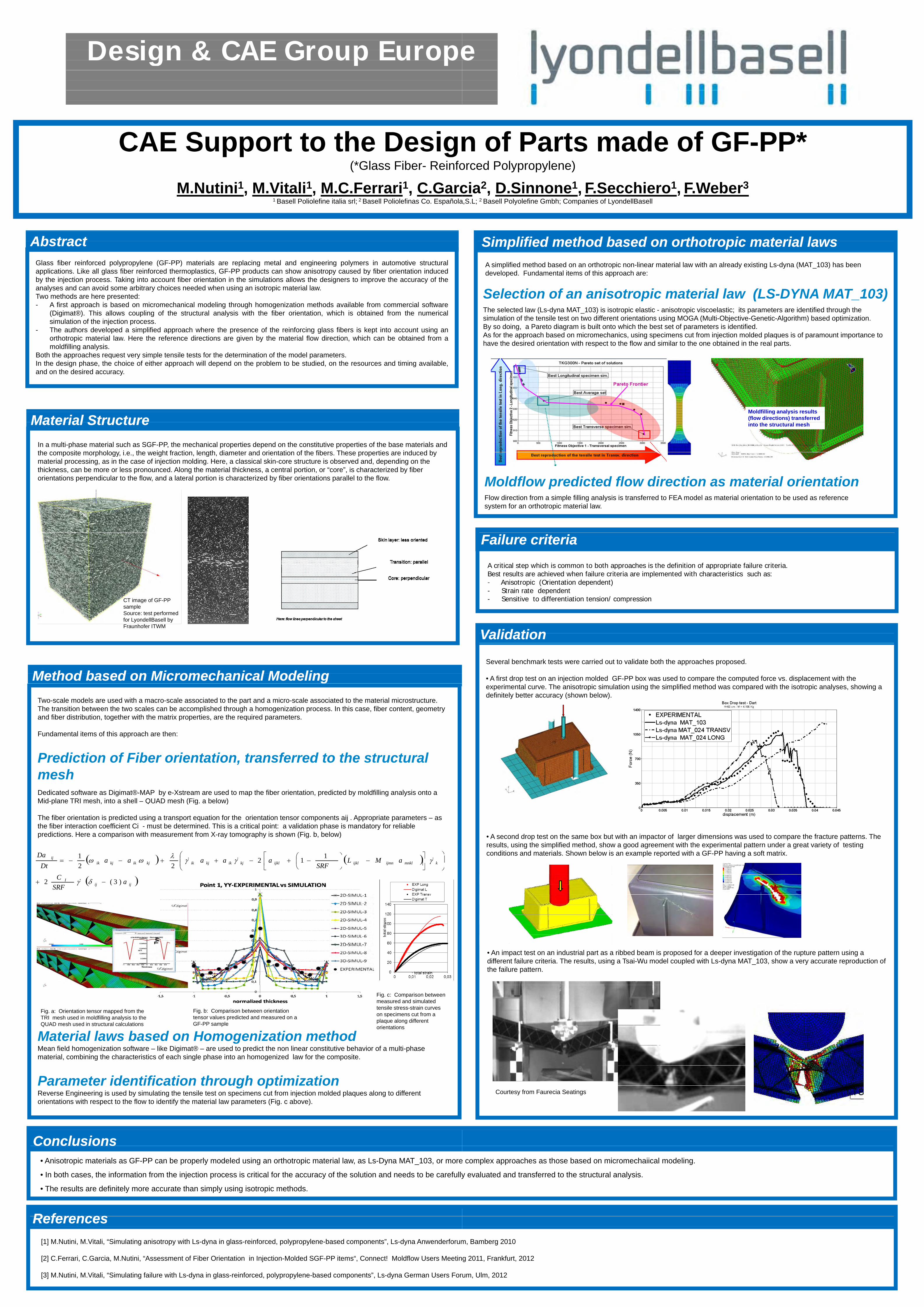
• A first drop test on an injection molded GF-PP box was used to compare the computed force vs. displacement with the experimental curve. The anisotropic simulation using the simplified method was compared with the isotropic analyses, showing a d fi it l b tt ( h b l )definitely better accuracy (shown below).
A d d t t th b b t ith i t f l di i d t th f t tt Th• A second drop test on the same box but with an impactor of larger dimensions was used to compare the fracture patterns. The results using the simplified method show a good agreement with the experimental pattern under a great variety of testingresults, using the simplified method, show a good agreement with the experimental pattern under a great variety of testing conditions and materials Shown below is an example reported with a GF-PP having a soft matrixconditions and materials. Shown below is an example reported with a GF PP having a soft matrix.
• An impact test on an industrial part as a ribbed beam is proposed for a deeper investigation of the rupture pattern using aAn impact test on an industrial part as a ribbed beam is proposed for a deeper investigation of the rupture pattern using a different failure criteria. The results, using a Tsai-Wu model coupled with Ls-dyna MAT_103, show a very accurate reproduction of the failure pattern.
Courtesy from Faurecia Seatings
e complex approaches as those based on micromechaiical modeling.
y evaluated and transferred to the structural analysisy evaluated and transferred to the structural analysis.
m, Bamberg 2010
2011 F kf t 2012g 2011, Frankfurt, 2012
um Ulm 2012um, Ulm, 2012