
CADRAIL Version 10.1.0.0 Instructions - Sandia Software Manual.pdfExample 1 - Your First CAD Drawing...
138
i CADRAIL Version 10.1.0.0 Instructions IMPORTANT NOTICE By installing the Cadrail software on your computer system, you are agreeing to be bound by the terms listed in this non-exclusive License Agreement: 1. Only one user is authorized to use this program on one computer. This agreement becomes effective when you show your acceptance by installing the computer software. SANDIA SOFTWARE grants you the right to make copies of the program and disc for the sole purpose of making backup disc for your own use only. You may not sell, distribute or network any part of this program package. 2. SANDIA SOFTWARE makes no warranty or guarantee as to the accuracy of the data produced by or contained in any portion of the Cadrail program and data files. The entire risk related to the quality or performance of the program is on you. These materials are provided "as-is". You agree to hold SANDIA SOFTWARE harmless against any type of legal action, liabilities or damages whatsoever arising from the use or inability to use this program.
Transcript of CADRAIL Version 10.1.0.0 Instructions - Sandia Software Manual.pdfExample 1 - Your First CAD Drawing...

i
CADRAIL Version 10.1.0.0 Instructions
IMPORTANT NOTICE
By installing the Cadrail software on your computer system, you are agreeing to be bound by the terms listed in this non-exclusive License Agreement: 1. Only one user is authorized to use this program on one computer. This agreement becomes effective when you
show your acceptance by installing the computer software. SANDIA SOFTWARE grants you the right to make copies of the program and disc for the sole purpose of making backup disc for your own use only. You may not sell, distribute or network any part of this program package.
2. SANDIA SOFTWARE makes no warranty or guarantee as to the accuracy of the data produced by or contained in any portion of the Cadrail program and data files. The entire risk related to the quality or performance of the program is on you. These materials are provided "as-is". You agree to hold SANDIA SOFTWARE harmless against any type of legal action, liabilities or damages whatsoever arising from the use or inability to use this program.

ii
Cadrail is a trademark of Sandia Software
Windows is a trademark of Microsoft Corporation.
© Copyright 1990-2017 Sandia Software All Rights Reserved

iii
Table of Contents
Chapter 1: Getting Started 1
Installing Cadrail 1
Learning about Cadrail 2
What's it called in Cadrail? 4
A Quick Tour 9
Saving the Drawing and Quitting 12
Chapter 2: Basic Drawing 13
Creating Drawing Objects 13
Editing an Existing Object 15
Object Properties 17
Chapter 3: Drawing Tutorials 21
A Simple Drawing using the Edit Freehand Tools 22
Example 1 - Your First CAD Drawing 26
Example Layout 2 - A Simple Oval 29
Example Layout 3 - Figure 8 with Elevations 35
Example 4: Using Styles and the 3d View 41
Chapter 4: Your View of the Drawing 44
The Drawing Coordinate System 44
Changing Your View of the Drawing 45
Setting Display Information for the Drawing. 47
Side Views 49
Chapter 5: Figures 50
Tools for Creating and Manipulating Figures 50
Defining Figure Properties with the Object Data Grid and Treeview 51
Chapter 6: Printing Your Drawing 57
Chapter 7: 3D View 59
Chapter 8: More Tool and Dialog Boxes 63
Layer and Styles Tool Bar 63
Drawing Manager 67
Preferences Dialog Box 70
Inputting Numbers with the Toolbars 73

iv
RMB Popup Toolbar 75
Shape Builder Dialog Box 76
Insert Picture 77
Picture Paint 77
Using the Profile Dialog 78
Importing, Exporting and Converting 79
Work Sheet 80
Miscellaneous 81
Chapter 9: Runrail 82
Drawing Requirements 82
Runrail Operations 83
Chapter 10: Railroad Design 87
Model Railroad Scales and Clearances 87
Advanced Railroad Drawing Techniques 88
How to Draw Railroad Switches (Turnouts) 94
How to Draw Railroad Yards 96
How to Draw a Siding 97
How to Draw a Crossover 98
Drawing Artwork 99
Chapter 11: Common Questions 100
Basic Drawing Questions 100
Setup Program Questions 102
Converting from Earlier Versions of Cadrail 103
Printing Problems 104
Chapter 12: What’s New in Version 10 105
Appendix A: Drawing Tools 107
Edit Tool Group 107
Line Tools 118
Circle Tools 121
Spiral Tools 123
Symbol Tools 125
Special Drawing Tools 127
Appendix B: What’s On the DVD? 130

1
Chapter 1: Getting Started
These instructions provide information about using the Cadrail application. The document is available as the application help file or as an optional printed manual.
Installing Cadrail The first step to begin using the Cadrail application is to install the software on your computer system. Prior to installing the software you should verify that you meet the minimum system requirements.
Cadrail Requirements You must have the following computer equipment to operate the Cadrail application:
• A PC or compatible computer running Microsoft Windows Version XP, Vista, 7, 8, or 10 • A display monitor and graphics card running resolution 1024 x 768 or higher • A mouse (center scroll wheel optional but recommended). • A hard disk drive with a minimum of 20 MB available. • A DVD disc drive (for optional disc).
Installing Cadrail on Your System The following instructions explain installation from the optional DVD. If you have the downloaded version of Cadrail, see the instructions at the web site where you purchased the product. Follow these instructions to have the Setup Program install Cadrail on your hard drive.
1. Make certain that your computer and monitor are turned on and Windows is running. 2. Close any other applications that are currently running on your system. 3. Insert the Cadrail disc into the proper DVD drive and close the drive bay door. 4. If the setup program does not start automatically after inserting the DVD and waiting a minute, use
the appropriate run commands for your operating system to locate and run the file SETUP.EXE located in the root directory of the Cadrail distribution disc.
5. Follow the instructions on your screen as the Setup Program installs Cadrail. The Setup program will copy all of the application files to your hard drive and create the appropriate icons or menu items for Cadrail. Should you have problems with the Setup program, see the chapter Common Questions of this manual. A file named README.TXT may be included in the root directory of the distribution disc and may contain additional instructions. For information on using the Windows operating system consult the documentation supplied by Microsoft.

Chapter 1: Getting Started
2
Starting Cadrail You can start using Cadrail after you have run the Setup program to install the application onto your computer. Start the Cadrail application as you do any Windows program. To Start Cadrail:
1. Click the Start button on the Windows Task Bar.
2. Select Programs, Sandia Software, Cadrail 10, Launch Cadrail 10 from the menu.
You can learn more about starting applications and using the Windows operating system in your Windows Documentation.
Learning about Cadrail Your Cadrail package includes the Cadrail computer application with Help files, printed manual, and drawing libraries. Complete instructions are supplied as both the manual and Help files. The information in both documents is the same. You may read the printed manual as you would any book or view the Help files on the computer screen. If you are new to computers or to the Windows operating system, you should practice with your computer before attempting to understand Cadrail. Study the Microsoft Windows Documentation. Get familiar with Windows and drawing by running the Paintbrush program that is included with Windows. Practice sketching simple lines and circles in Paintbrush. How to use this manual There are three general parts to this manual. The first chapters contain information about basic Cadrail operation. This is followed by discussion of issues relating to model railroading. Finally, detailed instructions are presented for each individual drawing tool in the Appendix. To start learning Cadrail, you should read the basic drawing chapters and then familiarize yourself with the drawing tools and dialog boxes in the Appendix. Practice with the basic drawing tools for making lines and circles. Then work through the example layouts in the Drawing Tutorial Chapter. Even if you are an experienced user, you should still read the entire manual and tutorial. Keyboard commands are shown in <bold> type in this manual.
Click to Start Cadrail
Windows Start Button

Chapter 1: Getting Started
3
How to use the Program Help files Help files are computerized documentation that you view at the computer. Start the Help file system by starting the Cadrail application, selecting Help from the Cadrail menu bar and then selecting Contents on the menu (or press the F1 key). If you need instructions on using Windows Help, select How to Use Help on the Windows Help menu. Tool Tip Help will appear in the main Cadrail application window if you place the mouse pointer over a button or text box on the application. You can get Help on individual drawing tools by clicking the Right Mouse Button on the tool icon in the Drawing Tool bar. Sandia Software Technical Support Services If you have questions about Cadrail operations, you should first look in the manual, or consult the program Help. Practice each drawing tool or dialog box using a new practice drawing until you understand how it works. You should read the manual several times. Each time you look at the manual you will see information that you missed the first time through. Check the chapter Common Questions at the end of this manual and the file ReadMe.txt on the distribution disc for your problem prior to contacting technical support. If your question relates to the Windows operating system or your computer/printer, please contact the vendor of that product. When you call technical support, please be at your computer and have the appropriate documentation or materials available. Be prepared to give the following information:
• The version number of the Cadrail Program. • The type of computer equipment you are operating. • Exact wording of any messages that appeared on the screen. • A description of the problem and what steps you have taken to solve the problem.
Voice Technical Support is available from Sandia Software between 9:00 A.M. and 4:00 P.M. Mountain time, Monday through Friday. For voice technical support regarding Cadrail call (505) 821-0014. Electronic support services are available 24 hours a day, 7 days a week. To contact technical support by e-mail, send electronic mail from the Internet to [email protected]. Generally you will receive a response within 24 hrs. Visit the Sandia Software web site at: http://www.sandiasoftware.com for new information that may be available. This site is also available at: http://cadrail.com.

Chapter 1: Getting Started
4
What's it called in Cadrail? Many parts of Cadrail are similar to those in other Windows applications. Use the illustration to familiarize yourself with them.
Bottom Tool Bar
Main Menu Bar
Top Tool Bar
Scroll Bars
D rawing Tool Bar
Drawing Ma nager
Cadrail application window. The Main Menu Bar Select many of Cadrail’s features using the standard Windows drop down menus (see your Windows documentation for operation information as needed) located on the Main menu bar. Many of the menu items may also be selected using various tool bar buttons or the menu Shortcut Keys (described in other sections of this manual). Bottom Tool Bar The Bottom tool bar Displays the current drawing coordinate position of the Mouse Pointer and allows you to specify coordinates while drawing (just click the numbers on the tool bar). All of these features are described in detail in separate sections of the manual.
Change in X, Y, Z Coordin ates
X, Y, Z Coordinates
View Win dow

Chapter 1: Getting Started
5
Introducing the Top tool bar The Top tool bar contains the features that you'll use to manipulate your drawing. When you select an option (by clicking on it with the mouse) the program will respond by showing additional dialog boxes or giving you the next step on the Instruction Line.
File Open
F ile Save Z oom In F ence
Zoom In Last View
Ortho Snap
Show All
Objects
Grid
Zoo m Out
Current Drawing Tool Instruct ion Line
Current Layer &
Style Properties Redraw
Many of the functions on the Top tool bar may also be accessed using the Main Menu bar. All of the features are described in more detail later in this manual. A summary of the Top tool bar features follows.
File Open Lets you load and then edit an existing
drawing file.
File Save Saves the drawing file you are currently
editing.
Print Activates the Print dialog box.
Zoom in Fence Set the view to the area you enclose with a
rectangular fence.
Last View Change back to the previous view of the
drawing.
Show All Objects Set the drawing view large enough to
show all the objects in the drawing.
Zoom In Magnify the view size.
Zoom Out Expand the view size.
Grid Draws a Grid of equally spaced lines on
the drawing.
Snap Moves Mouse Pointer at equally spaced
increments you specify.
Ortho Set of tools for drag and drop drawing.
Current Properties Display
Currently Selected Layer and Style
Top tool bar features.

Chapter 1: Getting Started
6
Keyboard Operations Cadrail has many Keyboard Shortcuts that you can incorporate as you draw. Any drawing tool command can be ended by pressing the Escape key. Furthermore, you can Click the Right Mouse Button (RMB ) in the Plan View drawing area and then select Cancel from the Popup Toolbar. Selecting a new Drawing Tool is another way to cancel the previous operation. You can mix commands with the Keyboard and Mouse by typing the appropriate Shortcut key (hot key) or pressing the appropriate key while at the same time pressing a mouse button down. For example, hold down the Shift key and Click the RMB in the drawing Plan View (ie Shift + RMB ) for the RMB Popup toolbar . The Shortcut keys are displayed in Cadrail on the drop down menus of the Main menu bar.
Description Shortcut (Hot Key) Escape (stop command) Esc key or RMB
Get End (snap to object end point) Shift + LMB
Get Object (snap to object) Shift + LMB
Cancel/Activate Auto-Align Ctrl +LMB
Cancel/Activate Auto-Trim Ctrl + LMB
Cancel Figure Selection Ctrl + Shift + LMB
Define in Fence Ctrl + LMB
Help Contents F1
Zoom In Fence F2
Zoom to Last View F4
Zoom In F5, Page Down
Zoom Out F6, Page Up
Redraw Screen F7
Show All Objects F8
Zoom to Object F9
Scroll View Left, Right, Up, Down Arrow Keys
Open File Ctrl + O
Save File Ctrl + S
Save File As Ctrl + A
Print Dialog Ctrl + P
Drawing Manager Ctrl + M
3d View Ctrl + D
Side View Ctrl + E
Undo Ctrl + Z
Redo Ctrl + Q
Delete Ctrl + Del
Copy to Clipboard Ctrl + C
Paste from Clipboard Ctrl + V
Position: Bring to Front Ctrl + F
Position: Send to Back Ctrl + B
Drawing Toolbar Home Ctrl + X
Drawing Toolbar Move to Mouse Ctrl + RMB
Popup Mini Drawing Toolbar RMB
Pan Drawing Screen RMB + drag
LMB = Left Mouse Button RMB = Right Mouse Button

Chapter 1: Getting Started
7
Mouse Operations A mouse allows you to interface with the computer. You give the computer information about what you want to do using the mouse.
Moving Move the mouse pointer across the screen by moving (sliding) the mouse with your hand on the desktop.
Pointing Use the mouse pointer to move over an object on the screen.
Clicking Press the left mouse button down and then immediately release it. Be careful not to move the mouse between down and up.
Double Clicking Press and then quickly release the left mouse button twice in a row.
Dragging Point to an object, press the left or right mouse button, then slide the mouse. Hold the mouse button down while dragging.
Selecting Move the mouse pointer over your selection, and then click the left mouse button. Press the left mouse button to select something. Press the right mouse button to cancel or quit the command in progress (cancel does not change the selected drawing tool, it just resets the tool to the first step in the command). To change to a new drawing tool, simply select a new tool or other feature.

Chapter 1: Getting Started
8
Mouse Pointer Shapes You can interface with the computer using the mouse. As you move the mouse with your hand, the Mouse Pointer moves in unison on the screen. The mouse pointer is normally the standard arrow shape. However, the pointer may change shape during certain mouse operations. The shape the mouse pointer takes tells you something about the operation you can perform. The following table shows the pointers you may see while drawing.
Select Object
Select Point (Coordinates)
Dimension Fixed Length
Dimension Fixed Angle
Dimension Fixed Length and Angle
Dimension Fixed Radius
Dimension Fixed Length and Radius
Dimension Fixed Radius and Angle
Dimension Fixed Elevation
Move Freehand
Extend
Rotate
Ortho On
Mouse Pointer Shapes

Chapter 1: Getting Started
9
A Quick Tour In this section a quick overview of Cadrail’s features is presented. You can follow along step by step with the computer while reading. Opening an Existing Drawing You can open an existing drawing right after you start Cadrail or any other time you are working in the program. Drawings can be opened (and saved) from any directory on any drive. 1. Select the File menu from the Main Menu bar. 2. Select Open from the menu. 3. Choose the drawing you want from the Open dialog box. A second method to open a drawing is to simply click the Open button on the application tool bars.
1. Select the Open button on the Top Tool bar. 2. Choose the drawing you want from the Open dialog box. If you currently have a drawing open, you do not need to close it in order to open a new drawing. To see how Cadrail displays a drawing, start by opening the Tutor.crw drawing, one of the library files in the Cadrail folder: 1. Start Cadrail. 2. Select FILE - OPEN from the Main Menu bar. 3. Use the File-Open dialog box to select the drawing TUTOR.CRW located in your Personal Drawing
Library . The user library was created when you first started Cadrail. If you did not install the library you can do it anytime using the Re-install Personal Library button on the menu Options - Preferences – Program Setup Tab.
1. Click here to
select the drawing
2. Click here to accept the drawing you selected
Drawing File Open Dialog

Chapter 1: Getting Started
10
After you have selected the name of the drawing and clicked the Open button on the dialog box, Cadrail will read the drawing you selected, and then display the drawing objects on the screen. You can learn how to draw the Tutor.crw drawing in the Drawing Tutorial Chapter of this manual.
Drawing Tabs Once drawing has finished, you can see the name of the drawing file on the Drawing Tab that was created when you opened the file. As you open additional drawings, additional tabs are created. You can switch between the drawings by clicking the tabs. Click the X (close) button at the right of the tabs to close the active tab drawing.
Drawing Area and Coordinate System
Cadrail allows you to see your drawing from many view points. After you open a drawing, what you see on the computer screen is a portion of the drawing that appears as it would when viewed from above. This overhead view window is defined as the Plan View. What you see on the computer screen is also influenced by the position of the outside border of the Cadrail application window. You can change your window on the Plan View at any time using various features in Cadrail. Several of the features for setting your drawing window allow you to specify a coordinate system to view. The Tutor drawing (that you opened in the previous section) has been saved with the Grid option turned on so that you can see the drawing coordinate system. Note that the X coordinate axis extends horizontally across the drawing from left to right. This coordinate system is simply an imaginary system of squares that you can use in the drawing to represent distance in real life.
Drawing Tabs
Plan View
X
Y

Chapter 1: Getting Started
11
You can use whatever units you wish for your drawing coordinate system. To specify the units, use the Options- Preferences dialog box (selected from the Main Menu). The important thing to remember is the dimensions in your drawing are a representation of the dimensions in real life. The easiest way to change your drawing view size is to zoom in and out using the Center Mouse Wheel (CMW). As you scroll the wheel the drawing size in the view window will be enlarged or reduced. To move the drawing left, right, up, and down without resizing you can drag the Plan View screen using the Right Mouse Button (RMB). As you drag the drawing is translated without changing the size. Use the Zoom In or Zoom Out tools on the Top tool bar to magnify or reduce the size of the drawing on the screen. Drawing Tool Bar You create and edit drawing objects in the Plan View window by choosing a tool on the Drawing Tool bar. . After a tool has been selected the tool name is shown above the Drawing Tool bar buttons and the Instruction Line will show the first step to execute a drawing action.
Selecting a Tool on the Drawing Tool Bar. You can move the Drawing Tool Bar on the screen by dragging the header at the top. To dock the tool bar, click the < button in the upper left, press, Ctrl+X shortcut key, or drop the tool bar near the upper left corner of the Drawing Screen. Use the Right Mouse Button RMB Popup Toolbar .Popup Toolbar along with the Drawing Toolbar when convenient.
Click the Individual Tool Button
Chapter 1: Getting Started
12
Saving the Drawing and Quitting When you are finished drawing you need to save your work and exit the Cadrail program.
Saving and Naming a Drawing It's a good idea to save your drawing often. To Save a drawing, select Save from the File menu on the Main Menu bar (or click the Save button on the Top Tool bar). Cadrail automatically saves the drawing in the current directory, on the current drive, using the current drawing name. If you have not named the drawing yet, the Save As menu will appear. To change then name a drawing, select Save As from the File menu. Once the Save dialog box appears, type the new file name in the File Name text box. Cadrail files use the extension (the three letters after the ".") of CRW. Once you have entered the file name, click the OK button on the dialog box to save the drawing and close the dialog box. Starting a New Drawing You can start a new drawing any time you are working with Cadrail. A new drawing is created at startup so you may immediately begin drawing in the Plan View drawing area. To start a New Drawing simply select the item New on the File menu (on the Main Menu bar). You do not have to close the drawing you currently have open when starting a new drawing. Cadrail will create a new Drawing Tab for the drawing. To Quit Cadrail Select Exit from the File menu on the Main Menu bar to end the application. If you have made changes to your drawing, Cadrail asks if you would like to save the drawing. Choose yes to save the drawing changes. If the file already exists, it will be overwritten.

13
Chapter 2: Basic Drawing Cadrail is a Vector based Computer Assisted Design (CAD) program. What you draw becomes a mathematical Object in the drawing. There are seven types of objects in Cadrail: Lines, Circles, Spirals, Symbols, Text , Pictures and Figures. Vector objects can be copied, moved, or resized without loss of accuracy. This is what gives CAD its power. You do not get these options with a paint program where you simply edit a bitmap of individual dots. As you work on your drawing you will perform actions that fall into one of two categories: Creating an Object or Editing an existing Object. To create objects in the drawing, you first choose a drawing tool that makes the object the size and shape you desire in the drawing. You can create an object with approximate dimensions at first, and then use additional editing tools to further refine the object later, or you can select a tool that helps you make the object exactly how you want it the first time. You can find detailed instructions for each individual drawing tool in the Appendix of this manual. You should review the Appendix directions for each tool as they are presented in this manual.
Creating Drawing Objects Perform the following steps to create an object in the drawing: 1. Tell Cadrail what drawing tool you want by selecting a tool from the Drawing tool bar (see Chapter 1). After you
select a tool, Cadrail shows the name on the Top tool bar and displays the first step for the tool on the Instruction Line.
2. After selecting a tool, perform the steps required for the tool. Each step is shown on the Instruction Line. 3.
After selection the tool is shown here. The first step for the tool is shown on the
Creating Your First Object
Let's look at an example of creating a single Line: 1. Select the Line-Free Hand tool on the Drawing tool bar. The Instruction Line asks you to: 1. Select the first end point
of the new line. 2. Move the mouse pointer into the drawing view area of the screen. Notice that the mouse pointer shape changes from
an arrow to a cross. 3. Press the left mouse button (LMB) down in the drawing area and keep holding the button down. This point will
indicate the first line end point location (tool step 1 on the Instruction line). Next, the Cadrail Instruction Line shows you step 2.

Chapter 2: Basic Drawing
14
4. Keep holding the mouse button down and move (Drag) the mouse to a second (or opposite) end point location for the Line (tool step 2 on Instruction line). As you move the mouse the Line you are creating is shown on the screen as a temporary line tracer. The length and azimuth of the Line are shown in the Dimension Options area of the Bottom tool bar.
1. Left mouse button down at First End Point
Drag the mouse.
2. Release mouse button at Second End Point.
5. Release the mouse button at the second end point of the Line. This completes all the steps for the Line-Free Hand
tool. Cadrail will save the Line you created in the drawing and reset the tool to step 1. You should review the Appendix for more detailed instructions of each drawing tool. In the Appendix section on the Line Tools you will find a step by step schematic for the Line-Free Hand tool. All of Cadrail’s drawing tools are described the same way in the Appendix. Ending a Tool Command Once you have performed all of the steps in a drawing tool, Cadrail resets the tool to the first step. If you want to use the tool again, simply perform the drawing steps again. You do not have to select the tool again to repeat the same tool. If you wish to use a different tool, select a new tool on the Drawing tool bar (or select any feature from the Top tool bar or menus). You may end and reset a drawing tool in progress at anytime by selecting a new tool from the tool bars or menus. You may also reset a command in progress by pressing the right mouse button and selecting Cancel from the Popup Toolbar (optionally, press the Esc key on the keyboard).

Chapter 2: Basic Drawing
15
Editing an Existing Object Once an object has been created in the drawing, you may want to change or Edit the shape. Cadrail has many different tools that help you change object geometry. The Edit tool group on the top half of the Drawing tool bar contains many of the tools for changing objects.
Changing objects with the Edit tools Some of the Edit tools can be operated in two different ways. These dual use tools allow you to either edit objects in Freehand Edit Mode which follows standard Windows syntax of selecting an object and then selecting a tool, or you can edit following the CAD tool syntax where one first selects the toolbar button and then selects the object in the drawing area. There are times when it is more convenient to use one or the other of the two methods. The Freehand Edit Mode uses Windows drag and drop techniques that let you quickly move objects in your drawing and connect them together end to end. You can drag object handles to resize and manipulate the objects in your drawing. Move objects on the screen by dragging and dropping the body of the object. In freehand mode you first select the object in the drawing and then select the tool for the operation you want to perform. CAD edit mode tools let you first select a specific tool button and then select the object and perform the tool functions. CAD mode is the reverse of freehand editing where you first pick the object and then the tool. The dual use tools are located in the top rows of buttons on the drawing tool bar. You can perform the same functions with either freehand or CAD edit mode. The only difference is the ordering of the tool operation steps. Not all tools on the Edit tool group have a freehand mode due to their function. Finally, the CAD tool operation allow you to quickly perform repetitive loops of the same tool.
Editing with Freehand Edit Mode The Edit Freehand Tools. use typical Windows drag and drop syntax that you may be familiar with from other drawing software. Freehand tools are located in the top rows of the Drawing toolbar buttons. To see how the Edit Freehand Tools work, Copy the Line created earlier: 1. Select the Edit Freehand Tool button on the Drawing Tool bar (if already selected you don’t need to select it again). 2. Select one of the existing lines in the drawing (click on it). Note that Cadrail highlights the object and shows edit
handles on the ends.
3. Select the Copy button on the drawing tool bar. Cadrail will then create a copy of the line located adjacent to the original in the drawing.
4.
2. Select the Line
3. Click the Edit-Copy button
Copy
1. Select Edit Freehand Tool

Chapter 2: Basic Drawing
16
Now you can practice moving the lines in the drawing area by dragging them. Select a line and then click on some of the other dual use freehand buttons and watch what they do. Drag the handles that appear on the object after you select it. We will learn more about the drawing tools later. More detailed explanations of all the tools available are summarized for quick reference in the Appendix. If you decide you don’t like what you just did, you can select the Edit-Undo command on the Main Menu bar to restore the last edit you made to an object. When you select Undo, Cadrail will reverse the last drawing command performed. To reverse an undo, select Redo from the menu.. These features are also available on the Popup Toolbar you get by clicking the Right Mouse Button (RMB) in the Drawing area, the Drawing Manager Object Data Grid and the Figures Treeview.
CAD Editing Mode CAD mode syntax is similar to that used when creating objects. To change an object, first be sure that no object is already selected in the drawing area, then select the specific Edit button on the Drawing tool bar. After you select a tool button, follow the steps shown on Cadrail’s Instruction Line (normally to select the existing object in the drawing area). For example, to copy the Line created previously, you can select the Copy tool on the Edit tool bar:
1. Select the Edit-Copy Object tool on the Drawing tool bar. Be sure that no object is selected in the drawing area (if an object is selected, press the <esc> key or right mouse button to cancel).
2. Move the mouse pointer over an existing Line in the drawing. Press the left mouse button down on the object and
hold it down. 3. Drag (keep pressing the button and move the mouse) the Line to the new copy location and then release the mouse
button. Cadrail creates a copy of the line at the drop location.
2. Press left mouse button down on existing object and keep holding the button down.
3. Drag to new location and release the mouse button.
In the previous example, you first selected the tool you wanted on the tool bar. Next you selected the object you wanted in the drawing. Finally you performed some drawing action on the object. Notice that when you were done, Cadrail reset the selected tool back to step 1 and you could have used the tool again without selecting it from the tool bar. This repetition of the CAD tools comes in handy when you need to perform the same drawing action many times.

Chapter 2: Basic Drawing
17
Object Properties There are six types of objects that you can create in your Cadrail drawing: Lines, Circles, Spirals, Symbols, Text and Figures. Each type of object has its own set of properties. Name Cadrail names drawing objects with an object number. The object number consists of its numeric position in the data base followed by the first letter in the type of object (Line, Circle, Spiral, Point Symbol, Text, and Figure). Numbering begins at object 10. For example, the first line you create in a drawing will be called 10L. If you make a second object that is a Circle it would be named 11C. You may use the object number to specify an object instead of clicking on the object with the mouse (see Object Number Input). Use the Object Number Display option button (see Display Options) on the right of the screen to make the object numbers visible on the screen. Style and Layer Drawing objects can have many types of line Styles and can be assigned to any available drawing Layer. The object line Style determines whether the object is drawn as a solid line, a dashed line or one of the other custom Styles. Objects are grouped and colored according to the drawing Layer the object is assigned to. Modify the Layers and Styles available in your drawing using the Layer and Styles tool bar located on the Current Properties button Flyout Toolbar and the Drawing Manager Properties Tab.
You can select the Layers to show on the drawing screen using the Visible property on the Layer and Styles tool and you can Freeze individual layers in the drawing. See more details in the Drawing Manger Properties Tab section of the manual. When you create an object, the properties currently set on the Layer and Styles tool bars will be assigned to the object. The Current Drawing Properties that are selected on the Layer and Styles toolbars are displayed on the Current Properties button on the Toptool bar and at the top of the Drawing Manager Properties Tab. You may change an existing object’s properties at any time using the Change Properties drawing tool or edit the object using one of the Object Data Grids (See Drawing Manager). Import the Layers and Styles from a second drawing using menu items File - Import (see Import-Layers and Styles). See other sections of the manual for more details on the Edit Layer and Styles dialogs.
Current Properties Layer and Style Flyout Toolbar
Drawing Manger Layer and Styles Toolbar

Chapter 2: Basic Drawing
18
Object Geometry Basic terms used in Cadrail are defined in this section.
Line Objects Cadrail thinks of a line as the space connecting a beginning point (X1, Y1, Z1) and an ending point (X2, Y2, Z2). The computer remembers each point on the screen or drawing as X, Y, and Z Cartesian coordinates in space. This geometry gives every end point coordinates that relate it to all the other end points on the layout. To help describe a Line, we define the Length as the shortest distance between the end points. The direction of the line is termed the Azimuth. Azimuth is a term for the angle of the line measured clockwise from a reference direction. North is normally the reference direction and on the computer screen, north is defined as up or at the top of the screen. A negative Azimuth is measured counter-clockwise from the reference direction.
Arc and Circle Objects Circles and Arcs are simply bent lines. They consist of a beginning point and end point. A circle has an additional property that forms the shape of the curve. All parts of the circle are an equal distance from the center or radius point. This distance is termed the radius. End points of circular arcs have special definitions in surveyor’s and engineer’s terms. The beginning point is known as the Point of Curvature (PC) while the ending point is called the Point of Tangent (PT). To relate better to these definitions, remember that our objective will be to connect circles with lines in a continuous alignment. This requires a single unique line fit to the end of a curve. A line of this type is defined as being tangent to the circle or a tangent line.
PC PI
Delta
PTDelta
r
Radius
A typical Circular Arc
Tangent Line
Radius
Point
L
Azimuth
Length Y1
Y2
X1 X2
( X2,Y2 )
A typical Line

Chapter 2: Basic Drawing
19
If you measure the angle between the tangent of a curve and its radius it will be 90 degrees (the corner of a square or perpendicular). The point of curvature (PC) is where you move from the straight line tangent onto the curve. The point of tangent (PT) is where you move from the curve back onto a straight line tangent. All this movement is in one direction just like a train travels down the track. Another important point used to describe a curve is Point of Intersection (PI) of the two tangent lines. Looking at a circle in terms of the tangent and radius line and their intersections is very useful because you can avoid reference to the complication of the curve itself. Just layout a series of straight lines, then go back and fit in the curves later with a specific radius. Delta is defined as the angle made at the PI by the two tangent lines. A neat property of a circle is that the delta angle between tangents is equal to the angle between a radius line to the PC and a radius line to the PT. Finally, the Length of Curve (L) is the distance along the circular arc from the beginning (PC) to the end (PT).
Spiral Objects The spiral curve (or easement) is a special shape which is most easily described as a circular curve at one end point and a line at the other end point. The spiral transitions from a straight line to a curve. This transition occurs at a uniform rate by varying the radius of the spiral curve. At the straight or tangent end of the spiral (TS), the radius is infinite (a straight line). At the opposite end (SC), the radius of the spiral is equal to the radius of the connecting circular curve.
A simple mathematical property of the spiral is that the length of the radius varies inversely with the length of the spiral. For you mathematicians, the following two relationships apply to spirals:
r = R ( L )
t F =
( t ) 3
6 ( R ) ( L )
t is the length along the spiral from the TS
r is the radius at point t
F is the offset to a point on the spiral
Point Symbol Objects Point Symbols represent a single spot in space. They have an X, Y and Z coordinate. You can use the flag and tree Symbols to indicate features of your drawing or you can use Points as handy place holders for constructing your drawing objects. The Point drawing tools provide easy ways of generating precise angles and distances in your drawing. When you select the Symbol Point tool the Symbols Popup Toolbar is shown in the drawing area. Here you can select Point or Tree Symbols.
Delta
R
L
TS
SCF
A typical Spiral

Chapter 2: Basic Drawing
20
Text Symbol Objects You may create, place and edit Text Symbols on your drawing just like any other object. Text can be part of a Figure or it can be copied and moved. Double Click the Text to edit in the drawing area.
TEXT STRING Click here Text Height in
Drawing Units
Rotation
The size of the Text you create in Cadrail is based on the same coordinate system as the other objects. You specify the Height of the Text in drawing units when using the Text tools. See the discussion for the Symbol Text tools in the Appendix.
Picture Objects A Picture Object is a rectangle shape containing a picture image. Many common picture file formats are supported. Pictures have all the properties of the other Cadrail objects and can be used with any applicable tool. Each corner of the picture rectangle has a X, Y and Z coordinate.
Picture Objects in the Cadrail drawing.
There are several ways to create a Picture Objects in your drawing. First, you can use Insert Picture tool (Top Tool Bar) to include a picture from a file you select. Second use the menu items Edit Copy/Paste to copy new pictures into your drawing from other applications or from other Cadrail drawings. Finally you can create Figures that include your pictures and use the Figures Toolbox to copy the Figures into your drawing.
Figure Objects (Group) Figures are a group or collection of objects. Once you have defined the objects in a Figure group, you can use the Figure tools to perform a drawing command on all the objects in the Figure. Figures can be saved to disk, and then later copied into different drawings using the Figure toolbox. A Figure may be a continuous alignment of connecting objects or it can be a scattered collection. Cadrail includes many Library drawings that are simply regular drawings of various things. In these drawings groups of objects such as a building have been defined as Figures. See the Chapter on Figures for more information.

21
Chapter 3: Drawing Tutorials Step by step instructions for drawing several track plans are presented in this Chapter. You should look over the rest of the manual and practice drawing simple lines and circles before, during and after drawing the example layouts. As you work through the Tutorials, refer to the detailed instructions for each tool in the Appendix. You can find more tips on drawing railroads in the Chapter on Railroad Design. You can draw with Cadrail using two general approaches. First, you can work with the pre-drawn Library Figures that are supplied with Cadrail. Second, you can create your own objects using Cadrail’s custom drawing tools. You can mix the two methods any way you like. In the first example drawings, you will work with the tools in a snap-together fashion using Freehand Edit Mode. In the remaining examples you will work with the CAD style drawing syntax. You can mix and combine tools any way you like.
Quick Tips for Using Cadrail There are some simple methods you should follow to help Cadrail as you are drawing. Keep things as simple as possible for the program when it needs to find an object. Most tools require Cadrail to search for an object in the drawing. Try to click in an area of the drawing where there is no mistake about the object you want (you may use the Edit - Input Object command on the Main Menu to enter the object number of problem objects).
Click near the midpointwhen selecting objects
Click here Not here
Click here
Not here
Avoid Horizontal andVertical pointsClick here
Not here
Click on the object whenselecting end points Avoid other objects
Click here
Not here
To Select an object, you should click somewhere on the body of the object. Don’t click on the exact ends. Instead click near the center of the object. To help determine the object to be selected, use the Auto-Find option to highlight the objects the mouse pointer is over. There are many ways to select the object you need. You can Drag a Fence around several objects or select objects in the Figures Treeview. When you select an object end point, remember that Cadrail must first find the object, then the end point. Try to click on the body of the object. You don't have to be on the exact end point. Anywhere on the object half with the end point that you want is close enough. Be sure to save your drawing often while you are working on it. If you mess something up, you can reload an old version. Proper backup procedures can save many hours of lost work.

Chapter 3: Drawing Tutorial
22
A Simple Drawing using the Edit Freehand Tools In this first example you will create a simple diamond polygon with 4 sides. Follow along performing each step carefully using Cadrail. 1. Create a Free Hand Line in a new drawing (refer to the instructions in the previous chapters if you need help). 2. Select the Edit Freehand Tool on the Drawing Tool bar.
3. Select the Line in the drawing area (click on it with the Mouse Pointer). 4. Click the Copy button on the Drawing tool bar. Cadrail will create a copy of the selected object and locate it in the
drawing slightly offset from the original. 5. Click the Copy button two more times so you have a total of four lines in the drawing. 6. Select one of the Lines in the drawing (if not already selected) and then drag one of the handles (small Green
Square on the ends of the Line) so that the Line slopes at an angle in the opposite direction to the remaining lines.
Drag
7. Click the end of a Line while holding down the <Shift> key on the keyboard (to GET the END of the Line) and then Drag the body the Line over the end of the rotated Line (move any of the Lines around in the drawing to make room to work as needed). When the Line ends cross, release the left mouse button while holding down the <Shift> key on the keyboard. Cadrail will bring the two Line end points together so that they match exactly. Repeat this step with another Line so that you form the third side of a box or polygon.
Drop + <Shift>
to Get the End
3. Select the Line
4. Click the Edit-Copy button
Copy
2. Select Edit Freehand Tool
Chapter 3: Drawing Tutorial
23
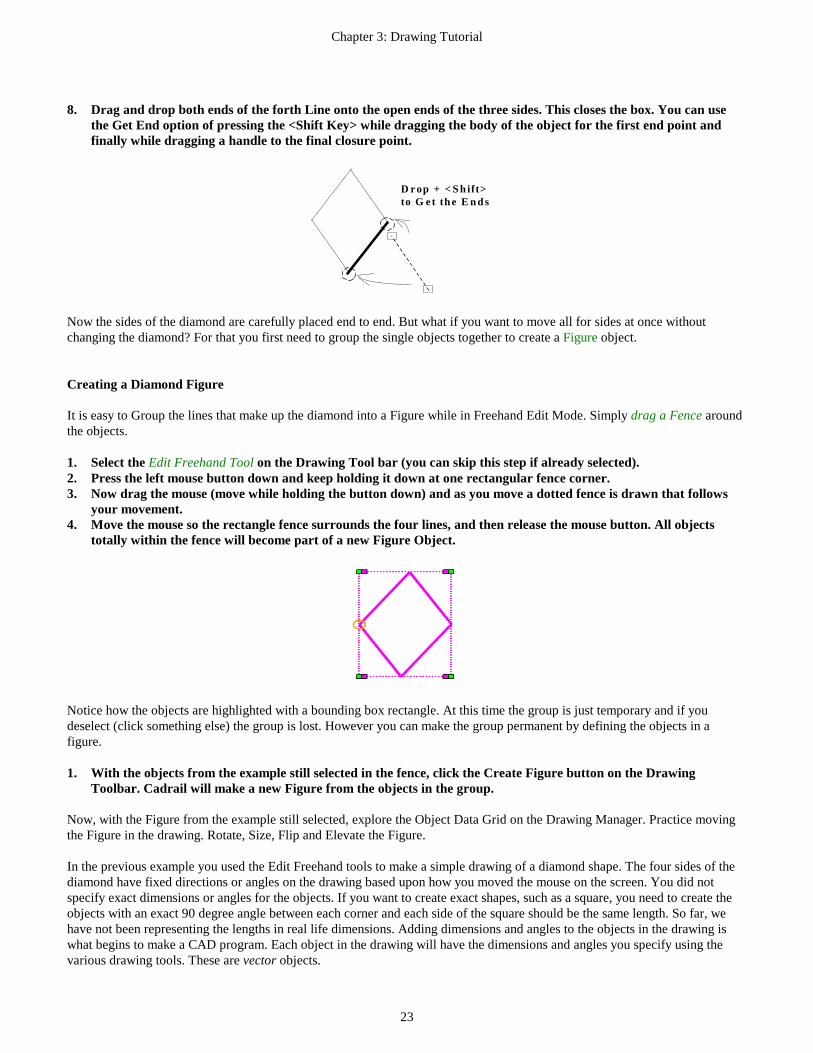
8. Drag and drop both ends of the forth Line onto the open ends of the three sides. This closes the box. You can use
the Get End option of pressing the <Shift Key> while dragging the body of the object for the first end point and finally while dragging a handle to the final closure point.
D rop + < Sh ift>to G e t the E nds
Now the sides of the diamond are carefully placed end to end. But what if you want to move all for sides at once without changing the diamond? For that you first need to group the single objects together to create a Figure object. Creating a Diamond Figure It is easy to Group the lines that make up the diamond into a Figure while in Freehand Edit Mode. Simply drag a Fence around the objects. 1. Select the Edit Freehand Tool on the Drawing Tool bar (you can skip this step if already selected). 2. Press the left mouse button down and keep holding it down at one rectangular fence corner. 3. Now drag the mouse (move while holding the button down) and as you move a dotted fence is drawn that follows
your movement. 4. Move the mouse so the rectangle fence surrounds the four lines, and then release the mouse button. All objects
totally within the fence will become part of a new Figure Object.
Notice how the objects are highlighted with a bounding box rectangle. At this time the group is just temporary and if you deselect (click something else) the group is lost. However you can make the group permanent by defining the objects in a figure. 1. With the objects from the example still selected in the fence, click the Create Figure button on the Drawing
Toolbar. Cadrail will make a new Figure from the objects in the group. Now, with the Figure from the example still selected, explore the Object Data Grid on the Drawing Manager. Practice moving the Figure in the drawing. Rotate, Size, Flip and Elevate the Figure. In the previous example you used the Edit Freehand tools to make a simple drawing of a diamond shape. The four sides of the diamond have fixed directions or angles on the drawing based upon how you moved the mouse on the screen. You did not specify exact dimensions or angles for the objects. If you want to create exact shapes, such as a square, you need to create the objects with an exact 90 degree angle between each corner and each side of the square should be the same length. So far, we have not been representing the lengths in real life dimensions. Adding dimensions and angles to the objects in the drawing is what begins to make a CAD program. Each object in the drawing will have the dimensions and angles you specify using the various drawing tools. These are vector objects.

Chapter 3: Drawing Tutorial
24
Creating an Arc To create an Arc in the drawing we again turn to the Drawing tool bar. Follow the steps carefully clicking at each point in the arc. 1. Select the Circle-PC to Radius tool in the Circle Drawing tool group. 2. Click the mouse in the drawing area and then move the mouse. You will see a circle moving on the screen as you
move the mouse and one point on the circle is fixed where you first clicked. This first fixed point is defined as the PC.
2. PC
3. Radius
4. PTThis is the segment
you want
Move
3. Now that the PC is fixed on the drawing, continue to define the circle by moving the mouse in the direction of the
radius point (this is the PC-Radius tool). Cadrail shows a circle tracer as you move. The tracer circle has a fixed point at the PC and your mouse position is defining the radius as you move. You can use this tracer to see the circle you are creating. Move the mouse to the location you want for the center of the circle (radius point) and release the mouse (or click the mouse). This fixes the radius of the circle.
4. With two points fixed, the position of the circle is fixed in space. All that's left is to locate the other end point of the circular arc. Move the mouse from the PC around the circle in the direction you want the body of the arc (clockwise in our example). Cadrail will draw a tracer on the screen that sweeps out the angle and arc you are creating. Your mouse position defines the angle to the PT from the radius point. Now click, and the PT is set. The Arc is complete after defining the three points PC, Radius Point (or center) and PT.
There are many ways to draw circles and arcs. You can align them and rotate the arcs using the various tools on the Drawing Toolbar or by moving the handles that appear when you select an object using the Freehand Edit tool (the big arrow button upper left of the Drawing Toolbar). To learn the various tools you may read the detailed instructions in the Appendix for each tool on the Drawing toolbar. These same instructions are available with the Application Help file. To see the detailed instruction for a tool on the Drawing Toolbar simply click the button with the Right Mouse Button. A help window will appear for the tool. Aligning Objects End to End Automatically In the last example you created an arc in the drawing. Now we want to take a step towards creating an alignment of connected objects. In our alignment, end points of the objects will match exactly and the objects will be aligned tangentially at the end points. These big words may worry you but in simple terms a tangent line is simply the smoothest connection between an arc and a straight line. Cadrail provides several tools for Aligning objects together end to end. When the Auto Align feature is on, you can and drag and drop objects together while in Freehand Edit Mode. You could optionally use the Align CAD tool which is more accurate when defining the objects to align. In this example we will use the Edit Freehand Tools with Auto-Align: 1. Create two Lines and an Arc in a drawing. If you need help with this step, see the previous examples. 2. Select the Edit Freehand Tool (if Freehand Edit is already selected you can skip this step). Click on the Auto-Align
button the Top Tool bar so it is ON (the button will be down and highlighted).

Chapter 3: Drawing Tutorial
25
3. Drag and drop one of the lines onto one end of the Arc so that the bodies of the objects cross. If the endpoints are close together when you drop the objects, Cadrail will activate Align and begin showing an object tracer on the screen.
Drag & Drop
4. Move the Mouse Pointer around the end of the Arc so you can see the tracer jump into two possible locations on the
end of the arc. When the tracer shows the Line facing away from the Arc, click the mouse to fix the position in the drawing.
Move the Mouse
5. Repeat the procedure to align the second Line onto the other end of the arc.
You can see that using different combinations of the Get End tool and the Align tool you can quickly and easily connect objects together end to end. But, you still have not given the drawing any real life dimensions.

Chapter 3: Drawing Tutorial
26
Example 1 - Your First CAD Drawing The first step in creating a new drawing is to define an overall drawing size. This drawing size is simply a temporary drawing view window we will look at on the computer screen. The view size can be changed at any time. It is just used to specify to Cadrail what to show on the computer screen. The following example purposely exposes you to the details of setting the view and using Cadrail’s more advanced features. There are many ways to make your drawing but you should be familiar with the basic concept of sizing the drawing and drawing to size. Before we begin please note that we are assuming that the AutoFind feature on the Top Toolbar is off in these examples. You may have it on if you like and then when the mouse pointer is over objects that are valid for the tool, the object will be highlighted. This highlight shows you if you click now you will select the highlighted object. You will need to set a view size slightly larger than the overall dimensions of what you are going to draw. Our example layout will fit on a 4'x8' sheet of plywood in real life. Therefore, a nice view size for the drawing window might be 10. This shows the entire 8' width of the layout with some space left over on the outside edges of the drawing. Furthermore, the number 10 lends itself to division by increments of 5, 2, 1, .5, etc. Define a view size for the drawing by clicking the Left Mouse Button (LMB) on the Enter View Size button found on the Bottom Toolbar (or select View-View Width from the Main Menu bar). Enter the view size after the Input Toolbar appears. A step by step example follows. 1. Enter 10 in the Plan View Width text box.
Enter the Values into the Input Text Boxes. 2. Next, define the coordinates for the lower left corner of the drawing window. If the lower left drawing coordinates
are defined as X = 0 and Y = 0 (0,0) the coordinates that will be visible on the screen will be all be positive. Therefore, enter values of 0 for the lower and left coordinate in the dialog box (the dialog box has 0 values when first opened).
3. Accept the view settings you have entered by clicking the OK button on the dialog box. Cadrail will hide the dialog box and redraw the screen with the new size.
As you work with the Input Toolbar you will notice the upper Instruction Window gives comments about how to enter the values. To help visualize the drawing coordinates, turn on the optional coordinate Grid on the Top Tool bar: 1. Move the mouse pointer over the Grid Increment on the Top tool bar and then click the mouse on the box. The
Input Text Box will be shown where you can enter the value for the Grid Increment. Type a grid increment of 0.5 in the dialog box. Press the Enter key (or click the OK button) to accept what you have entered and then the dialog box will hide from the screen.
2. Now that the Grid increments have been defined, click the Grid toggle button on the Top tool bar to turn it on. The button will be highlighted (the button looks down) when the grid is on and Cadrail will draw grid lines on the screen at the increment you specified.

Chapter 3: Drawing Tutorial
27
With the grid defined you can see the drawing coordinate system on the computer screen. Note how the X axis on the bottom shows coordinates from 0 to 10 (the Plan View width you entered) and the Y axis at right shows coordinates from 0 to 5 (your screen may vary depending on your window size). The drawing width has been fit to your current Cadrail application window and size of the vertical axis will depend on the size of the application window. To make the vertical size bigger or smaller, re-size your Cadrail application window. For our example, we will work in units of feet. Therefore the Plan View Width of 10 drawing units (as defined previously) will represent 10 feet in real life. The units are defined on the Options- Preferences (Main Menu bar) dialog box and will already be set to Feet when you start Cadrail (check the setting if you want). In this example we will create a drawing using one of the pre-drawn libraries of track figures that are supplied with Cadrail. These library files are simply Cadrail drawings of things like track, buildings or scenery. To begin drawing using Figures that are supplied with Cadrail, you must first Open a drawing into the Library Figures Tab on the Drawing Manager: 1. Click the LMB on the Library Tab of the Drawing Manager 2. Next Click the File-Open button on the Library toolbox to specify the drawing you want to load. 3. When the Open dialog box appears on the screen, select the file HO_A100.CRW (if you need to, review File-Open in
Chapter 1 of this manual). Cadrail will fill the Figures toolbar with a list the Figures in the Atlas HO drawing file. To copy a figure from the Figures toolbox into your current drawing: 1. Find the figure named A821 9”S (Atlas product 821 a 9” straight track) in the Figures tool box list (you may need
to scroll the list down). Then move the mouse pointer over the Figure in the toolbox. Press the left mouse button down on the Figure and hold it down. Drag the mouse (move the mouse while continuing to hold the button down) to the drawing area. The mouse pointer will change to the Windows Copy Arrow.
2. Drop (release the mouse button) the Figure into your drawing (if asked to create a new layer and style answer yes). Cadrail will place a copy of the figure into the drawing.
Library Tab
Figures File Open Button
Drag and Drop
The Figure we just dropped into the drawing is now so small on the screen you may need to Zoom In so that the drawing is bigger. Use the Center Mouse Wheel (CMW) to zoom around the current mouse pointer location in the drawing. Use the Right Mouse Button (RMB) to drag the drawing on the screen. There are many ways to change your view. Click the Zoom In button on the Top tool bar a few times. If you need to, use the scroll bars to center the Figure in the view window. You should now be able to see that the Figure is a simple centerline drawing of a straight piece of Atlas HO track. A single Line object of the correct length represents the track section. To see the Figure names on the drawing screen, select the Figure Numbers Display Labels option button on the Top Tool bar. While you are there, turn on the End Point labels. The track section Figure name and number are now shown on the drawing and the ends of the line have small circles around them. The next object you need in the drawing is a section of curved track. Drag and drop the track Figure named A833 30C18 (Atlas 833, 30 degree curve, 18” radius) from the Figures Library into your drawing. Next we want to start making an oval from the end of the straight track. To move the curve onto the end of the straight track in the switch, use the Align tool (refer to the Appendix as needed):

Chapter 3: Drawing Tutorial
28
1. Select the Edit-Align Object tool on the Drawing tool. 2. Click on the right end of the curved track Figure. As you move the mouse a tracer of the curved arc is drawn and
follows your mouse pointer. 3. Move the mouse pointer over the right end straight track Figure and then click the mouse (release the button). 4. Now as you move the mouse pointer 360 degrees around the end of the Line, watch the Arc as it jumps orientation
to four possible quadrants around the end of the line. Move so the arc curves down and to the right of the straight track. Once the curved track is oriented, click the mouse to lock the Arc in place. Cadrail will move the Arc Figure and rotate it to the new position.
Align
Now the Arc is tangent to the Line and the ends match exactly. For the next step, make 5 copies of the curved track Figure: 1. Select the Edit-Copy Object tool in CAD mode. 2. Drag and Drop the original curved Figure to a new location on the drawing. Cadrail will create a copy of the
Figure at the new location. 3. Repeat step 2 until you have 5 copies of the Figure (6 curved Figures total).
Copies
Use the CAD Edit-Align Object tool again to align the remaining curved track sections end to end so they form a half-oval as shown. Use the Zoom tools to re-size your view of the drawing if needed.
Using the Align tool with the Library Figures in this fashion allows you to “Snap-together” any railroad layout you can dream up using fixed track sections. Continue working with this drawing if you want. Pull out a switch (turnout), complete the oval, whatever you want. You may want to save your drawing. In this drawing, all of the objects have exact real life size dimensions that represent the actual real life model track. The library drawings were simply created with Cadrail using the proper dimensions of Atlas HO track. Working with sectional track like this limits the shapes you can make because you are working with fixed, pre-drawn sections. If you want to start working with flex track and other variable shaped objects, you need to start using more powerful CAD tools as demonstrated in the next example.

Chapter 3: Drawing Tutorial
29
Example Layout 2 - A Simple Oval In this example you will create a simple oval (a completed drawing is included with Cadrail and named TUTOR.CRW in your Personal Cadrail Drawing folder on your hard drive as described in Appendix B). As we start drawing, we are going to use some of the advanced tools in Cadrail that let you draw with exact dimensions and angles. At first we will step through the hard core geometry theory of the CAD coordinate system and then move on to easier methods of doing the same thing. To begin the drawing, set up a new drawing following the steps explained in Example Layout 1. For our example the track board is a 4'x8' sheet of plywood. Draw the left edge of the board using coordinates: 1. Select the Bench work drawing layer by clicking the layer row on the Layer
and Styles toolbox. Be sure the layer is visible on the screen by turning it on using the Visible feature on the Layer and Styles toolbox. If you need help with the toolbox, see the detailed description in another part of this manual.
2. Select the Line-Free Hand tool on the Drawing tool bar. 3. For convenience, we will locate the first Line at a whole number coordinate by using the Coordinate Input Option.
Activate the Input Toolbar by clicking on the coordinate display on the Bottom Tool bar. Type values of X = 1 and Y = 1 (Z can be left blank or Z = 0). This coordinate point locates the lower left corner of the 4 x 8 rectangle at whole number increments of the coordinate grid. Click the OK button to accept what you have input. After the Input Toolbar closes, move the mouse over the drawing area and note that the first end point of the Line is now fixed at coordinate (1, 1, 0).
4. Locate the second end point of the vertical Line by inputting the coordinates (1, 5, 0) following the same method. After you input the second end point, Cadrail will create a Line between the two end points you just specified. Now you should have a single vertical line that is exactly 4' long showing on your drawing. Note the line has the layer color and style shown on the Layer and Styles tool. To draw the bottom edge of the 4x8 board, let's use the Line-Perpendicular tool. We know that the bottom edge is 8' long. So, to produce a line of this exact length, we will use the Length Dimension option on the Bottom tool bar: 1. Select the Line Freehand tool. Note that the Dimension options become visible on the Bottom tool bar. 2. Turn the Length Dimension toggle ON by first clicking the button on the Bottom tool bar (the button is highlighted
and pushed in or down). Next, when the Input Text box appears to the right of the button over the Length display, type a value of 8 in the box. Click the OK button on the Text Box or move the mouse out of the Text Box Area to set the length value. Notice that now when the mouse pointer is over the drawing it looks like the length toggle button image to indicate this option is on.
3. Select the Line-Perpendicular tool on the Drawing tool bar. 4. We want to start from the lower end point of the existing 4' line. To do this, use the Get End tool by holding down
the <Shift> key and then clicking the left mouse button while the mouse pointer is over the existing Line end point. Cadrail shows that it found the end point by drawing a small circle around it. You don't have to click exactly on the end point. Anywhere on the bottom half of the Line will do.
( 1, 1 )
( 1, 5 ) ( 9, 5 )
( 9, 1 )Example Layout
Type the coordinates in the boxes
Chapter 3: Drawing Tutorial
30
Existing 4' Line
Click near this end
while holding down the
Shift Key
CADRAIL GETs the END
Move in this direction,
to GET the END
then click
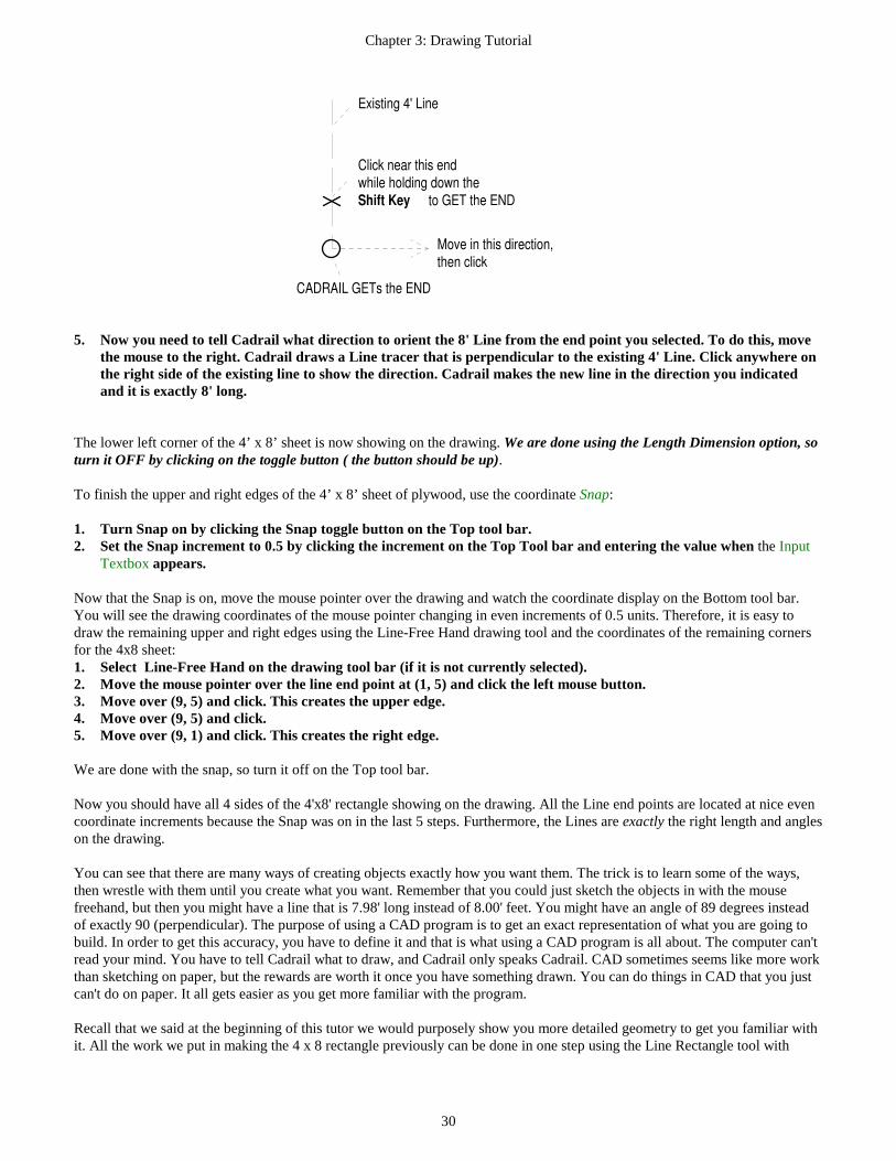
5. Now you need to tell Cadrail what direction to orient the 8' Line from the end point you selected. To do this, move
the mouse to the right. Cadrail draws a Line tracer that is perpendicular to the existing 4' Line. Click anywhere on the right side of the existing line to show the direction. Cadrail makes the new line in the direction you indicated and it is exactly 8' long.
The lower left corner of the 4’ x 8’ sheet is now showing on the drawing. We are done using the Length Dimension option, so turn it OFF by clicking on the toggle button ( the button should be up). To finish the upper and right edges of the 4’ x 8’ sheet of plywood, use the coordinate Snap: 1. Turn Snap on by clicking the Snap toggle button on the Top tool bar. 2. Set the Snap increment to 0.5 by clicking the increment on the Top Tool bar and entering the value when the Input
Textbox appears. Now that the Snap is on, move the mouse pointer over the drawing and watch the coordinate display on the Bottom tool bar. You will see the drawing coordinates of the mouse pointer changing in even increments of 0.5 units. Therefore, it is easy to draw the remaining upper and right edges using the Line-Free Hand drawing tool and the coordinates of the remaining corners for the 4x8 sheet: 1. Select Line-Free Hand on the drawing tool bar (if it is not currently selected). 2. Move the mouse pointer over the line end point at (1, 5) and click the left mouse button. 3. Move over (9, 5) and click. This creates the upper edge. 4. Move over (9, 5) and click. 5. Move over (9, 1) and click. This creates the right edge. We are done with the snap, so turn it off on the Top tool bar. Now you should have all 4 sides of the 4'x8' rectangle showing on the drawing. All the Line end points are located at nice even coordinate increments because the Snap was on in the last 5 steps. Furthermore, the Lines are exactly the right length and angles on the drawing. You can see that there are many ways of creating objects exactly how you want them. The trick is to learn some of the ways, then wrestle with them until you create what you want. Remember that you could just sketch the objects in with the mouse freehand, but then you might have a line that is 7.98' long instead of 8.00' feet. You might have an angle of 89 degrees instead of exactly 90 (perpendicular). The purpose of using a CAD program is to get an exact representation of what you are going to build. In order to get this accuracy, you have to define it and that is what using a CAD program is all about. The computer can't read your mind. You have to tell Cadrail what to draw, and Cadrail only speaks Cadrail. CAD sometimes seems like more work than sketching on paper, but the rewards are worth it once you have something drawn. You can do things in CAD that you just can't do on paper. It all gets easier as you get more familiar with the program. Recall that we said at the beginning of this tutor we would purposely show you more detailed geometry to get you familiar with it. All the work we put in making the 4 x 8 rectangle previously can be done in one step using the Line Rectangle tool with

Chapter 3: Drawing Tutorial
31
Ctrl+ to enter the dimensions. But we also need to learn the CAD basics like using the grid and snap and what things are named in Cadrail.
Tip: Have you saved your drawing recently? It is a good idea to save often. See Chapter 1 if you need instructions on saving. Change the name of the drawing now and then to create a backup (for example: MYPLAN2 then MYPLAN3). You might also want to click the Redraw button on the Top tool bar to refresh the screen.
The next step in our example plan is to start putting in some track. One of the easy ways of laying out an alignment is to define each end, then fill in the middle. This can be done by starting a plan using just the straight Lines at critical areas, then go back and turn the corners by filling in with circular curves or arcs. Optionally, put in the major curves at some of the restricting areas, then use Cadrail's special tools to fit in the connecting tangent lines. This is the approach we will use in the example plan. 1. Select the Layer: Track 1 on the Layer and Styles Toolbar. 2. Select the Circle-PC to Radius tool on the Drawing tool bar. 3. Make the left Circular Arc by first locating the PC (start of curve). Move to the PC and click the left mouse button.
Don't worry about accuracy for now. Just "eyeball it".
4. Now that the PC is fixed on the drawing, continue to define the circle by moving the mouse in the direction of the
radius point (this is the PC-Radius tool). Cadrail shows a circle tracer as you move. The tracer circle has a fixed point at the PC and your mouse position is defining the radius as you move. You can use this tracer to see the circle and how it fits in the layout. Move to about the center of the board vertically and click the left mouse button to fix the radius.
2. PC
3. Radius
4. PTThis is the segment
you want
Move
5. With two points fixed, the position of the circle is now fixed in space. All that's left is to locate the other end point of
the circular arc. The PC already fixed one end point, so now you need to set the PT end point. Move the mouse from the PC in the direction you want the arc (clockwise in our example) and Cadrail will draw an angle tracer that sweeps out the angle and arc you are creating. Your mouse position defines the angle to the PT from the radius point. Now click, and the PT is set.
You should now have a nice looking arc shown in your drawing. But, is it the size you wanted? Is it in the right location? You could have drawn the arc using the Radius Dimension option (just like the 8' perpendicular Line you made earlier). This would allow an exact radius of say 3' (36"). If you wanted the circle exactly in the center of the board, you could use the coordinate input options to locate the radius point at coordinate (3,3). You could use the Snap to locate the radius first, then the PC and PT (Radius to PC tool). Move the Arc using the Edit Freehand tool:

Chapter 3: Drawing Tutorial
32
1. Select the Edit Freehand Tool|tag=Selecting the Edit Freehand Tool. 2. To select the Circular Arc, move the mouse pointer over the Arc and press the left mouse button down. Cadrail
shows you the object it found by highlighting it briefly. 3. Continue holding the mouse button down and Drag the Arc to the new location. Cadrail will move the object as you
move the mouse (if you decide you don't want to move it after all, still holding the left button down, click the right mouse button to cancel the command).
4. Release the left mouse button at the new location to drop the object. This will fix the object coordinates and terminate the command.
The next step is to make the Arc on the right side of the drawing. You could draw it using the Circle tools, but we told you we would expose you to some advanced stuff in this tutorial so let’s just copy the existing circle on the left and then flip it to face the way we want: 1. Select Edit-Copy Object on the Drawing tool bar (be sure that no other object is selected so you are in CAD mode). 2. Press the left mouse button down on the existing arc. 3. Drag the Arc to the new location for the copied circle (just move it to the right for now) and then release the mouse
button at the new location. Cadrail makes a copy of the first arc at the new location, leaving the original arc unchanged.
Now lets flip the arc: 1. Select the Flip Left/Right drawing tool (be sure that no other object is selected so you are in CAD mode). 2. Click on the copied Arc and then Cadrail will flip it about a Y axis (vertical) to the direction we want.
Use the Freehand Edit tool to locate the flipped arc where you want it. You should now have two circular Arcs representing the two ends of the track oval. The next step is to connect the two Arcs with Lines on the top and bottom of the oval. This is easy with the Line Between Circles command: 1. Select the Line-Between Circles tool. 2. Click on the left circle at the approximate location for the PC of the top Line. 3. Click on the right circle at the approximate location for the PT of the top Line. Cadrail will construct a connecting
Line using the PC and PT points you selected at the closest of 4 possible tangent Lines between the two circles.
Click near the PC and PT,
this tangent Line is created
PC PT
Repeat the previous steps 1-3 for the Line on the bottom to complete the oval.

Chapter 3: Drawing Tutorial
33
In the last steps, when we used the Line between Circles tool, if you hold down the Ctrl key in step 3, Cadrail will automatically trim the unwanted portion of the arcs. You tell Cadrail to always trim automatically (without holding Ctrl+ ) by turning on Auto-Trim on the Top Tool bar. You can trim the Arc ends yourself with the Edit-Trim at End Point tool: 1. Select the Edit-Trim at End Point tool. We will divide the circular Arcs at the Line end points (PC or PT). 2. Click on one of the Arcs. Cadrail will highlight the object. 3. Click on the end point of the Line near where it intersects the circular Arc (PC or PT). You do not have to click
exactly on the end point. Anywhere on the correct half of the line will do. Cadrail divides the Arc at the Line end point. The result is two Arcs and one is the smaller portion that we don't want.
3. Click the Circle
4. Click here
Line end point
you want to Divide
for the
4. Select the Edit-Delete Object tool. 5. Click on the trimmed Arc. Cadrail will delete the Arc. Now you should have a perfect oval as shown below.
Note that because we just moved the Arcs into place with the mouse earlier, the Lines of the oval are not necessarily parallel to the outline of the board. It is important to understand that the points you click on the objects give Cadrail information about what direction the final objects should face. It you click on the opposite end of the arc in the last step 3 you will get different results. This will be more clear with other tools. To add the spur line into the center of the oval, use a switch figure from one of Cadrail's library files. The easiest way to insert a single figure into your drawing is to use the Figures toolbox: 1. In the Drawing Manager click the Library Tab at the top. 2. Click the Figure File Open button near the top of the Figures Tab, and then open the library drawing
HO_A100.CRW (see Example Layout 1). Once the drawing has loaded, all the Figures in that drawing are listed individually in the list box.
3. Drag and Drop the Switch (Turnout) Figure labeled A281 #4 into your drawing The switch goes on the lower end of the left Arc in our example. But, the lower line is in the way. Therefore, delete the lower Line of the oval. The Line has temporarily served its purpose to divide the Arc at the exact PC point. This end of the arc is at exactly the right place to allow a perfect tangent fit. All we have to do is align the switch to the end of the left Arc and fill in the blanks.

Chapter 3: Drawing Tutorial
34
IMPORTANT! Remember that when we made the two circles, we just placed them on the board freehand. Therefore, we must now assure that the switch has the correct orientation to match the end of the circle as a perfect tangent line. The Edit-Align Object tool does this nicely (if you know the switch has the proper orientation already you can skip Alignment and just Move the Figure, matching end points with Get End). 1. Select Edit-Align Object on the Drawing tool bar in CAD mode. 2. Click on the end point of the switch figure that will attach to the end of the arc. Cadrail automatically GETs the
end of the object in the Figure.
Align the switchat the ends
3. Click on the lower end point of the left Arc. 4. Move the mouse around the alignment point to get the switch orientation you want (away from the arc) and then
click the mouse. To check the last step, zoom in on the switch: 1. Select the Zoom in Fence button on the Top tool (or select it from View on the Main menu bar, or press the F2
shortcut key). 2. Select a corner for the Zoom window. 3. Select the opposite corner of the Zoom window rectangle. Cadrail will temporarily adjust the drawing size so that
the window you selected fills your current Cadrail application window. Does the switch still match at the end of the circle after Zooming In? It should if you want to maintain accuracy. A better way to make sure the endpoints match is to check the object coordinate values using the Drawing Manger. However, if the Align command was executed properly, and the visual clues Cadrail gave during the command looked good, then you can be fairly sure everything is exact without checking.
Extra Credit: use the Figure - Insert Turnout tool to place the Turnout (Switch) into your drawing with fewer drawing steps (Hint: no need to delete/recreate the Line).
Return to a larger View Size by clicking the Show All Objects button on the Top tool bar. You should now see the entire plan centered in the application window. We know that the end of the Arc and the end of the switch are properly aligned because we used the Line-Between Circles command and the Align command earlier. Therefore, use the Line tool with GET END to connect a Line from the end of the switch to the right arc lower end point (see the appendix if you need help with this tool). Our last step to finish the track work in this example is to extend the spur line from the switch. This is easy with the Line-Project tool: 1. Select the Line Tangent tool. 2. Press the left mouse button down on the diverging leg of the Turnout at the free end point while holding the <Shift>
key down. Cadrail will highlight the Line it found with a small circle around the end. 3. Drag the mouse pointer to the middle of the oval to begin creating the spur line. Cadrail will draw a tangent line
tracer as you move. When the new line tracer is the length you want for the spur, release the left mouse button at the opposite Line end point location. Cadrail then creates the new spur Line.
Congratulations! You have completed your first CAD layout with Cadrail. Compared with drawing on paper, using a CAD program can seem like a lot of work at first. In fact, it is. But, how many times have you drawn a layout on paper, then laid it out in real life and found the curve you put in doesn't match at the switch and the whole layout has to be readjusted? A little extra learning effort pays off handsomely in the long run.

Chapter 3: Drawing Tutorial
35
Example Layout 3 - Figure 8 with Elevations In this example, a simple figure eight will be drawn with elevations to show one track crossing over another. The overall plan will again be placed on a 4’ x 8’ sheet of plywood. At this point we could draw in the edges of the 4’ x 8’ board similar to the last example. However, it will be easy to copy the board outline created in the first example. To copy the first example, let’s define the board outline as a Figure (you should open your example plan 2): 1. Select Create Figure from the Drawing tool bar . 2. Click on one of the Lines that make the edges of the 4’ x 8’ board. 3. Continue defining the objects in the Figure by clicking on the remaining 3 sides of the board outline in clockwise
order. 4. After clicking on the fourth side of the board, tell Cadrail you are done with this Figure definition by pressing the
Right mouse button and select cancel (or the Esc key, or select the next command to be performed). Now that you have defined the board outline as a Figure, the next step is to make a copy of the Figure. But, first you need to increase the size of the Plan View so that there is empty space in the drawing window to copy the Figure into. Use RMB Drag and CMW Zoom or the Zoom tool and Scroll bars to adjust the view so that there is an empty space above the existing layout to place the 4’ x 8’ Figure. With the larger drawing size, there is plenty of room on the screen above the first example plan to copy the 4’ x 8’ board Figure: 1. Select Edit-Copy Object on the Drawing tool bar (be sure there is no object selected in the drawing when selecting
the tool as we want the tool in CAD mode). 2. Press the left mouse button down on the Line that makes the lower edge of the board outline. Cadrail should find
and highlight the Figure. 3. Drag the mouse to the upper area of the drawing. You will see an outline of the Figure move with you as you move
the mouse. When the Figure is clear of the first example layout in the upper area of the drawing, release the mouse button. Cadrail will copy all the objects in the Figure to the new location and create a second Figure definition.
Now you should have two 4’ x 8’ Figures on your drawing. Have you saved your drawing lately? You may want to save it with a new version number so that if something bad should happen to the new version, you still have an older version to fall back on. How about calling the new version of the drawing MYPLAN4.crw ? In this plan we will work in drawing units of inches (instead of feet as in the previous example). Go to the Options-Drawing Preferences (Main Menu bar) dialog box and select Inches for the drawing units. Click the OK button to accept the changes and close the dialog.. When you return to the drawing, turn on the Grid and note that the 8 feet side of the plywood rectangle is now 96 inches long. In this example, we will be more precise when placing the major circular arcs on the drawing than in the previous oval example. Assume we want to locate the Arcs of a figure 8 exactly 3 inches from the edge of the 4’x8’ board outline. This means the radius of the Arc needs to be (48-6)/2=21 inches.
3 units
3 units
21 units
21 units
One way to locate the Arc center or radius point would be to use coordinates or snap to locate it the proper amount from the corner of the 4’x8’ board. But, this requires you to manually add coordinates and some accuracy may be lost in rounding the

Chapter 3: Drawing Tutorial
36
coordinate values. Furthermore, if the lines were at an angle, it would be a difficult calculation. A better way, the CAD way, is to create the Arc center geometrically using the Cadrail tools. We know the Arc needs to be 3” from the edge and have a 21” radius so the Arc center point is located 24” ( 3 + 21 = 24 ) from the edge (it is in the center of the 48” or 4’ board). If we offset the board outline with two lines, the center of the Arc will be at the intersection of the lines:
24"
Intersection Point
1. Select the Edit-Offset Object drawing tool. 2. While holding down the <Shift>+<Ctrl> keys (to select the individual Line instead of the whole Figure), click on the
vertical Line that represents the left edge of the board. 3. When the Input Toolbar appears, enter a value of 24 for the offset distance. After you type the value press the Enter
key to accept what you typed (or click the OK button on the dialog box). 4. Click on the right side of the Line selected in step 2 to show Cadrail the location of the offset. Cadrail creates a new
parallel construction Line and it is exactly 24 units from the first Line. 5. Change these construction lines to a dashed line style by selecting the Dotted style and the Benchwork layer on the
Layer and Styles toolbox. Then select the CAD Edit - Change Properties drawing tool and click on the Lines to change their style to dashed.
Repeat the last steps to offset the bottom edge and the right edge of the 4x8. Now you have two crosses on the drawing and the intersections are the center locations we want for the new circular arcs. However, the intersection points do not yet exist in the drawing. To create a point at the intersection we must first divide one of the Lines at the intersection and then we can use this divided Line end point for the center of the new arc: 1. Select the Edit-Divide at Intersection tool. 2. Click on the horizontal construction Line. This is the Line that will be divided. 3. Select a vertical 24” offset construction Line. This Line forms the intersection point with the first Line. Cadrail then
divides the first Line selected at the intersection point. Repeat the previous 2 steps to form the other intersection point. Turn ON the Object and the End Point Display Label options to see the how the Line was divided in the last steps. You should see small end point circles at the intersections and there should be three Lines horizontally where the previous steps divided the original horizontal offset Line. You can see different object numbers for each of the three Lines. You can also see each object individually by selecting the object with the Edit Freehand Tool|tag=Selecting the Edit Freehand Tool Now that the intersection points have been established, you can create the arcs for the figure 8 and locate them exactly at the center of the board with exactly a 21” radius: We will create the arcs with one of the track layers so they can be distinguished from the bench work. Begin by drawing the arc on the left: 1. Select drawing layer Track 1 and style Solid 2 on the Layer and Styles Toolbar (if it is not already selected). Be sure
the layer is visible on the screen by turning it on. 2. Select the Circle-Radius to PC drawing tool.

Chapter 3: Drawing Tutorial
37
3. Select the Radius Dimension option button on the Bottom Tool bar to turn it on (refer to Example Layout 2) and then Input a value of 21 for the radius in the Dimension Text Box to the right of the button. Now, when you move the mouse pointer over the drawing area you will see the shape of the pointer has changed to indicate the Radius Dimension option is on.
3 units
PT
PC
1. Select the end point of the horizontal construction Line at the intersection point with the left vertical Line using Get End (Shift + Left mouse button). Cadrail will find the Line, find the end point of the Line nearest to where you clicked, and then draw a small circle highlight to indicate the end point it found.
2. Move the mouse to form an arc with the PC/PT at the approximate locations shown in the sketch. Since the dimension option for the radius of the circle is on, Cadrail will make the radius of the arc exactly 21 units.
Repeat the last 2 steps to create the Arc on the other side of figure 8. When you are done you may turn off the Radius Dimension option. Because of the way the lasts groups of steps were performed, the new Arcs are exactly 3” from the edge of the board. Check this by dividing one of the construction lines with one of the Arcs: 1. Select Edit-Divide at Intersection on the Drawing tool. 2. Click on one of the vertical construction Lines. 3. Select one of the Arcs near the intersection with the Line selected in step 2. Cadrail will divide the Line at the
intersection point. 4. Select the Edit Freehand Tool|tag=Selecting the Edit Freehand Tool. 5. Click on the small Line segment created in step 3 (if needed, Zoom In). Cadrail will show the Line data on the
Drawing Manager Object Tab. The Line length is 3.000 inches. Hopefully you are now getting more of a feel for how CAD works. There are many ways we could have made those last two Arcs. The important thing is they are now located at exact dimensions that we created in the drawing. In the second example layout, we never used exact dimensions for any of the track objects because they were drawn freehand with the mouse. Let’s quickly create the rest of the figure 8: 1. Select the Line-Between Circles Drawing tool. 2. Select one of the Arcs near the PT for one of the diagonal Lines of the figure 8. If you can’t click on the Arc near the
PT because the Arc you made is too short, you may need to use the Edit-Extend tool to lengthen the Arc. 3. Select the other Arc near the opposite Line PT. Cadrail will create the Line tangent to the two Arcs that has end
points nearest the PTs you selected in steps 2 and 3. Cadrail will automatically trim the ends of the Arcs to match the tangent Lines (when Auto-Trim is ON).
4. Create the opposite diagonal Line of the figure 8 following steps 2 and 3. The next step in our example is to add elevations or the Z axis dimensions to the drawing. In the figure 8, the Line that slopes diagonally upward and to the right will cross over the other Line. Because this is such a small length of track, we will have to immediately start rising in elevation at the intersection of the two lines. Then continue to rise around the Arc and back to the crossover. After the crossover, it is immediately back down. The grade or slope of the Lines will have to change at or near the

Chapter 3: Drawing Tutorial
38
crossover. Therefore, we must divide the Lines to create an end point where the grades will change. This type of grade change is called a vertical point of intersection (VPI). If we simply divide the two diagonal lines at the crossover point, two problems would arise. First, the track would have to make a sudden transition from up to down and this can derail the train. Second, Runrail would not work well on this plan because there would be four line directions at the intersection point without a switch. A better way is to have a short flat section at the crossover. This will help form a more gradual transition where the grades change.
Lets make the flat transition about 6” long and center it over the crossover (3” each side). To save time and effort we will just “eyeball” the dimensions in this step: 1. Select Edit-Divide at Point on the Drawing tool. 2. Click on one of the Lines approximately 3” from the crossover point. Cadrail will divide the Line near the point you
clicked on. 3. Repeat step 2 at the other 3 locations required. Now we can assign elevations to the figure 8. This is easy with the Profile Dialog once we first define a Figure for each grade up and down: 1. Select the Create Figure tool. 2. Select the upper left diagonal Line (see sketch). 3. Select the left Arc. 4. Select the lower left diagonal Line. 5. Press the right mouse button and select Cancel to stop defining the Figure. Repeat the last 5 steps to define the down grade Figure with the right Arc and diagonal Lines. Now give elevations to the end points of all the objects in the Figures using the Profile Dialog: 1. Select the Freehand Edit tool on the Drawing Toolbar 2. Select the left Figure (up grade) in the drawing. 3. Click the RMB in the drawing area to activate the RMB Popup Toolbar .. 4. After the Popup Toolbar appears, click the Profile dialog button on the Toolbar. 5. After the Profile dialog appears, enter values of 0 for elevation 1 and 4 for elevation 2. The grade value updates in
the dialog box as you enter the elevation values. With a vertical rise of 4” a grade of approximately 3 percent is produced in the example plan (your grade may vary).
Divide points for crossover lines

Chapter 3: Drawing Tutorial
39
Profile dialog showing the Tutor left upgrade Figure.
Repeat the last two steps for the down grade from 4” to 0”. Turn on the Show Elevations, Stations and Grades display labels and turn off the Objects labels to see each end point Elevation on the drawing screen. Select Options - Side View on the Main menu bar to see what you have done. After the side views appear, click the show all objects buttons for all three views to center the drawing in the view windows. Zoom in and out and scroll around to see the grade of the figure 8 rise up and cross over itself. Note that the Side view appears as it would when viewed from the side in real life. The circular arc appears to spiral in the vertical direction. Back in the drawing plan view, we can make the profile view continuous through the alignment of the two Figures that represent the loops at each end if we assign stationing to the Figures: 1. Select the left Figure (up grade). 2. Click the Right Mouse Button (RMB) in the drawing area and select the Profile item from the RMB Popup
Toolbar. 3. Enter a value of 100 for the Station. Now in the profile graph, look at the end point for the other end of the Figure
loop and note the value of 2+30.24 . 4. Select OK on the Profile dialog boxes to accept. Since the Show Elevations, Stations and Grades display labels were
turned on above, Cadrail will redraw the screen with the Stations shown for each end point in the Figures. Now that the left Figure has been given stationing you will see that the first endpoint in the Figure shows station 1+00.00 on the drawing screen. Zoom in and. in our example the other end of the Figure has station 2+30.24. At this time you can continue stationing around the alignment using the ending station of one Figure as the beginning station in the next: 1. Select the Create Figure tool. 2. Click on the small Line that forms the crossover between the up grade on the left and the down grade on the right
(the line slopes up from left to right) to define it as a Figure. 3. Click on the small Line in the Plan View and then open the Profile dialog using the RMB Popup Toolbar. When the
Profile dialog box appears, enter a beginning station of 230.24 (the end of the up grade Figure). Note the value for station 2 in the dialog box, you will need it later. In our drawing station 2 is 2+33.96 (your drawing may be slightly different). This is the beginning station 1 plus the length of the short Line: 230.24 + 3.72 = 233.96. Set Elevation 1 = 4 inches and Elevation 2 = 4 (this bridge is flat). Click the OK button to close the dialog box.
Be aware the exact station values in your drawing will be different than ours because we just clicked the divide points on the lines with the mouse. This is approximate and depends on where you click the mouse. So yours will be slightly different. 4. Select the Down grade in the drawing and open the Profile using RMB Popup Toolbar. 5. In the Profile dialog, enter Station 1 as 233.96. Set Elevation 1 = 4 inches and Elevation 2 = 0.
Enter the elevations
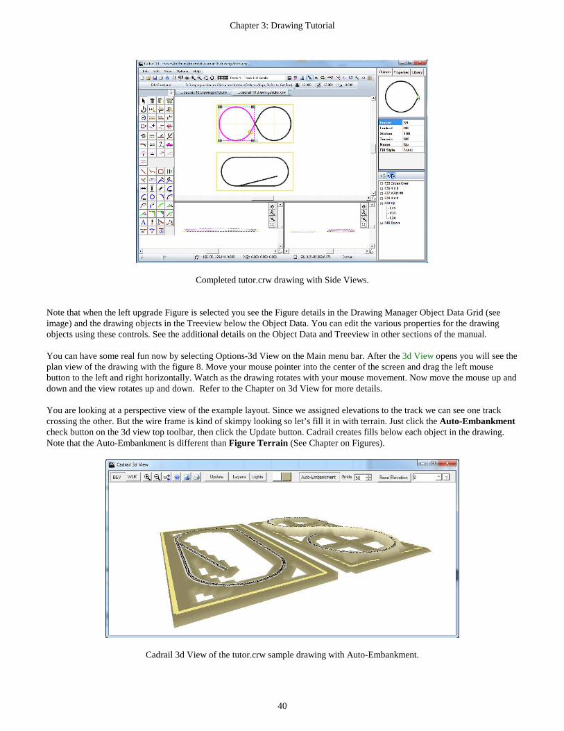
Chapter 3: Drawing Tutorial
40
Completed tutor.crw drawing with Side Views.
Note that when the left upgrade Figure is selected you see the Figure details in the Drawing Manager Object Data Grid (see image) and the drawing objects in the Treeview below the Object Data. You can edit the various properties for the drawing objects using these controls. See the additional details on the Object Data and Treeview in other sections of the manual. You can have some real fun now by selecting Options-3d View on the Main menu bar. After the 3d View opens you will see the plan view of the drawing with the figure 8. Move your mouse pointer into the center of the screen and drag the left mouse button to the left and right horizontally. Watch as the drawing rotates with your mouse movement. Now move the mouse up and down and the view rotates up and down. Refer to the Chapter on 3d View for more details. You are looking at a perspective view of the example layout. Since we assigned elevations to the track we can see one track crossing the other. But the wire frame is kind of skimpy looking so let’s fill it in with terrain. Just click the Auto-Embankment check button on the 3d view top toolbar, then click the Update button. Cadrail creates fills below each object in the drawing. Note that the Auto-Embankment is different than Figure Terrain (See Chapter on Figures).
Cadrail 3d View of the tutor.crw sample drawing with Auto-Embankment.

Chapter 3: Drawing Tutorial
41
Example 4: Using Styles and the 3d View In this example we will work with the drawing from the earlier examples to add detail and 3d structures (a completed tutor.crw drawing is included in the Cadrail folder that you can use here if you have not drawn your own tutor earlier). Furthermore, in this section we are not going to explain each tool in great detail. A lot of the information was presented in the earlier examples. 1. Open your tutor.crw drawing and save the drawing with a new name for a backup. 2. Open the Style Properties Editor by clicking the button on the Layer and Styles tool box. 3. Select Double Track in the drawing styles list at the left. After selection you will see the Style name in the text box at
the top center of the dialog box. 4. Now make the Line Width 0.1 inches and select Scalable. 5. Enter a centerline Offset Distance of 0.3 inches (HO scale). 6. Select a Fill Style from drop down list (solid). 7. Select a Fill color (light brown) 8. Close the dialog 9. Freeze the Benchwork Layer on the Layer and Styles toolbar. 10. Select the Layer named Track 1 and the Double Track line Style for the current property on the Layer and Styles
toolbar. 11. Select the Change Properties tool 12. Now drag a fence around the entire drawing to include all objects in both layouts (hold the Ctrl+ key to start the
fence). All Track 1 objects will be selected because the Benchwork Layer is Frozen. Now the track objects in the drawing should have the Double Track line style. You may need to Zoom In to see the ties.
Let’s put a fill in the 4 x 8 of the oval. Since the 4 x 8 Figure has already been created we can just use the Object Data Grid to make changes. 1. Un-check the Freeze property for the Benchwork layer on the Layer and Styles tool bar. 2. Select the Edit Freehand Tool|tag=Selecting the Edit Freehand Tool. 3. Select the 4 x 8 Figure in the drawing. 4. In the Drawing Manger Objects Tab use the Object Data Grid to select a Fill Style (gradient fill found right under
solid on the drop down list) and a Fill Color (green). Notice the drawing change in the Plan View. Something besides track would be nice now so we can add some buildings with little effort. Keeping the tutor drawing open in the Plan View, open the Building 3d HO.crw drawing located in your Cadrail folder. It will go into a second Plan View drawing tab, and the tutor drawing will still be open on another tab. Now we are ready to copy some buildings into the tutor drawing: 1. Select the Edit Freehand Tool|tag=Selecting the Edit Freehand Tool. 2. Highlight the depot (object number 1060F) in the buildings drawing (located between the roundhouse and
turntable in the drawing) by clicking on it. 3. Select Edit – Copy to clipboard from the Main Menu bar. 4. Select the drawing tab for the tutor drawing. 5. Select Edit – Paste from the Main Menu bar. A copy of the depot will appear in the center of the tutor drawing. 6. Move the depot along a section of track somewhere in the drawing. 7. Use the the Edit- Position- Move to Front/Back tool to bring one Figure on top of the others. Now repeat the same procedure and copy a couple of other buildings into the drawing. Save the drawing.

Chapter 3: Drawing Tutorial
42
Tutor3d.crw with 3D buildings and track styles in Plan View.
Open the 3D view and look at the drawing.
Tutor 3D view with buildings and track line style.
Note that the 3D shows some of the track and other pieces are covered by the 4 x 8. This is because the track and the board are at the same elevation. To help this we will raise the track slightly above the board. 1. Freeze the Benchwork and the Buildings layer in the drawing on the Layer and Styles tool bar. 2. Select the Edit Freehand Tool|tag=Selecting the Edit Freehand Tool. 3. Drag a fence around the track for the oval. You should be selecting the entire track for the oval including the spur
line. 4. While the track is selected, click the Create Figure button on the Edit Tool Group. Now all of the track in the oval
is one figure. 5. With the new track Figure still selected, click the Elevate button. Enter an elevation change of 2 (inches). 6. Unselect Layer Freeze for the Building and Benchwork layers. 7. Select the 4x8. 8. Click the Edit Elevate button. 9. Enter 1 inch change (we are raising this above zero so the terrain will fill around the board). 10. Repeat the procedure and elevate the buildings 1 inch to meet the 4 x 8.

Chapter 3: Drawing Tutorial
43
Now, click the Update button in the 3D view. You should now see the entire track. Select Layer Control on the 3D view and uncheck the Terrain for the Buildings layer. Close the Layer Control (move the mouse pointer away), select the Auto-Embankment check box on the 3D View top tool bar. Now click Update and look at the embankment terrain.
Tutor drawing with 3D buildings and Terrain.
Finally, you can easily add additional terrain using a Figure Terrain Grid|tag=3d Terrain Grid with the Terrain Fill Style option. Note this is not the same as the Auto-Embankment on the 3d view Top Toolbar. 1. Make sure the Benchwork layer is on Visible, then select the figure 8 layout 4 x8 outline Figure. 2. In the Object Data Grid, click the right column of the Terrain row and select ON from the Popup Toolbar.. 3. When the Input Toolbar appears enter a grid spacing of 1 foot, then click Ok. Now if you Double Click the Figure with Edit Freehand tool selected (or select Edit Terrain Toolbar from RMB Popup Menu) the Terrain Grid will be shown along with the Terrain Grid toolbar. You now enter the elevations for each grid square using the Terrain Toolbar to define the elevation, tool type, and then click the grid square to give it the toolbar elevation. See other sections of the manual for more details on Figure Terrain Grid.
Tutor3d.crw figure 8 with Figure Terrain Grid mountains.

44
Chapter 4: Your View of the Drawing Cadrail has many different options that allow you to define how much of your drawing appears on the screen and what information to show on the drawing. You may change your view at any time. You can look at your drawing from the overhead Plan View in the main drawing window. You can open additional Side Views. Finally, you can view the drawing in a 3D View which makes the drawing appear as it would in real life.
The Drawing Coordinate System For most people, the concept of assigning a coordinate system to what you see on the computer screen is one of the most difficult to visualize. Keep in mind that the computer screen size and the drawing coordinate system you use to represent dimensions in your drawing are completely different things. Your drawing dimensions represent how big you will build something in real life. To show this on the Computer, your life size drawing coordinate system must be reduced to fit on the screen (or printer paper). Cadrail can reduce (or enlarge) your drawing view on the screen by any factor. You may look at any rectangular window of your drawing at any time. Cadrail can do this because what it remembers about your drawing is simply a mathematical coordinate system and this coordinate system can be reproduced at any size on the screen. Therefore, sizing the drawing on the computer screen is simply a matter of telling Cadrail what drawing coordinate window to show. The concept of sizing the drawing on the screen is further complicated by the application window that Cadrail runs in on your operating system. Since you can resize the Cadrail application, you have a window on the drawing within a window on the computer screen. The outer window is the edge of the Cadrail application and your drawing is inside this window! The Plan View In Cadrail, the drawing background screen is defined as the Plan View. . This is the white picture box that you draw in and it can be re-sized within the visible Cadrail application window. When the drawing is shown in the Plan View, it appears as though you are looking down on what you are drawing.
Plan View
Side View
3 Dimensional View
Plan View
Side (Profile) View
X
Y
X or Y
Z
XY
Z
Your Drawing
Your Cadrail application window

Chapter 4: Your View of the Drawing
45
To tell Cadrail how big to make the drawing on the screen, you can specify the Plan View Width using View -View Width on the Main Menu bar or on the Bottom Tool bar. After the Input Toolbar appears, enter the values. The View Width defines how much of the drawing coordinate system to show in the drawing window. For example, if your layout was to be 8 feet long, then you could make the Plan View Width equal to 10 drawing units. This will leave 2 feet for the drawing borders. If you wanted to work in drawing units of inches, you would make the last example equal to 120 drawing units (10 feet x 12 inches/foot). Cadrail then fits the Plan View Width to the current application window. The maximum drawing Plan View size allowed in Cadrail is 999,999 units. The maximum drawing coordinate is positive or negative 9,999,999. You can define the lower left corner of the visible drawing plan view to any drawing coordinate that you like. By defining the view size and lower left corner coordinates of the drawing, you can look at any window in drawing space. In Cadrail, the X coordinate axis is defined on the Plan View horizontally from left to right. The Y axis extends vertically from bottom to top. There is a detailed example of how to set the View Size in Example 1 found in the Drawing Tutorial Chapter of this manual. You can easily navigate to a similar view as set above, using other features in Cadrail like the Zoom Tools and the drawing Scroll bars. These other methods are easier most of the time. However there are times when you need to set an exact value for the Plan View.
Changing Your View of the Drawing There are many ways to look at your drawing. In this section methods of defining the overhead or Plan View are described. The easiest way to move the drawing on the screen is using the Right Mouse Button to drag the drawing in any direction to the position you like. To Zoom the drawing plain view in and out, use the Center Mouse Wheel to size the drawing larger or smaller. You can also move your drawing view left, right, up or down using the Scroll bars on the bottom and right side of the Cadrail application. An additional option is to use the Keyboard Shortcut keys to change the view of the drawing. There are several ways of magnifying or reducing the size of the drawing on the screen. You can define a view size using the View-View Width dialog box found on the Main Menu bar and the Bottom Tool bar. You can quickly Zoom In or Out (magnify or reduce), or you can Scroll your view window Left, Right, Up or Down. All of the Zoom tools for changing your view are located on the Top Tool bar. The RMB Popup Toolbar . has some Zoom tools as well.
ZOOM IN FENCE Follow these steps to enlarge a selected area of the drawing. 1. Select the location of one corner of the Zoom window on the drawing Plan View.
2. Select the opposite corner of the Zoom window. Cadrail will temporarily re-size the Plan View so that the Zoom
window you select will fill your current application window on the screen. Cadrail will make the minimum dimension of the Zoom window you selected on the drawing match the minimum dimension of your current screen window.

Chapter 4: Your View of the Drawing
46
1.
2.
Move the Mouse
Zoom Window
ZOOM IN OR OUT You may magnify your drawing view by Clicking the Zoom In tool and reduce your view with the Zoom Out button on the Top Tool bar. You can also select Zoom In or Out from the View menu of the Main Menu bar. Click the button with the Right Mouse button to zoom smaller steps. Optionally, use the Center Mouse Wheel to Zoom In and Out or use the F5, F6, PgDn, PgUp shortcut keys. 1. Click the Zoom In button on the Top tool bar (if you need to, refer to the Top tool bar description earlier in this
chapter). 2. After you click, Cadrail will redraw the screen showing an enlarged or magnified plan view of the drawing. 3. Click the Zoom Out button. 4. Note that the drawing got smaller. You are back to your original size.
LAST VIEW Switch back to your last drawing view using the Last View feature (only valid if you have previously Zoomed In or Out). Last View may be selected from the Top Tool bar or from View on the Main Menu bar.
SHOW All OBJECTS If you select View-Show All Objects on the Main Menu bar or the Top Tool, Cadrail will enlarge the drawing view size to encompass all of the objects in your drawing. This tool can also be accessed on the RMB Popup Toolbar ..
DRAG SCREEN Press the Right Mouse Button down and drag the Plan View drawing area to the position you want.
REDRAW SCREEN You may tell Cadrail to Redraw the screen by selecting View- Redraw Screen on the Main Menu bar or Top Tool bar (or press the F7 shortcut key). Cadrail will clears the drawing screen, draws the objects, and the display options. The time it takes to redraw the screen will vary depending upon how many objects you have in your drawing and upon the active display features.
ZOOM TO OBJECT Change the Plan View Size to fit the size of the selected object. Optionally, press the F9 Shortcut Key.

Chapter 4: Your View of the Drawing
47
Setting Display Information for the Drawing. Cadrail has several features that allow you to show or hide parts of your drawing. You can choose optional information to be shown about the drawing objects using the Display Labels on the Top Toolbar). In addition, Layers allow you to organize the objects in the drawing into individual groups with different line colors on the screen. Then use the Layer and Style toolbars to make Layers visible or frozen.
Defining the Grid The Grid option on the Top tool bar lets you show a system of evenly spaced lines on your drawing. Each line in the Grid represents a single coordinate value extending across the drawing. To show the grid on the drawing, click the Grid toggle button to ON (pressed down). To specify the Grid increment (distance between each grid line), move the mouse pointer over the Grid increment display and then click the mouse. When the Input Text
Box appears, type the value into the text box, then press the Enter key to accept (or click the ^ button on the Text Box). When the grid is on, axis scales representing the drawing coordinate system are drawn on the screen.
Grid incrementPlan View
X axis
Y axis
To change the beginning coordinate value for the Grid Axis, set the coordinate of the drawing lower left corner using the View-View Width option on the Main Menu bar or the Top Tool bar. Grid increments in multiples of 1, 2, 5 and 10 work the best. If you specify a grid increment that will make the grid lines smaller than one eighth of an inch on the screen, Cadrail will display a message with the smallest allowable Grid increment for the current drawing view size. If you make the grid increment too large for your Plan View size, you may not see any Grid lines on the screen. The current Grid settings are saved with your drawing. Then, the next time you open the drawing, the Grid returns to the last saved settings.
Defining the Coordinate Snap Sometimes you may wish to have the mouse pointer move in even increments of some definable amount. The Snap option forces mouse movement in the drawing to the nearest Snap increment. You specify the Snap just like the Grid, click the Snap Increment display on the Top Tool and then when the Input Text Box appears, type a value for the Snap Increment (or spacing). Click the Snap button to toggle the Snap on or off. The snap increment operates independently of the grid increment and is saved with your drawing.
Ortho Mode Ortho Mode allows you to specify and exact angle when creating objects. To activate Ortho, click the button on the Top Tool bar. When the Input Text Box dialog box appears, type a value for the Angle. Click OK to accept. When Ortho is active, applicable tools will use the specified Ortho angle. For example, if you have Ortho set to 45 degrees, and draw a line, the line will be restricted to a 45 degree angle as you draw.

Chapter 4: Your View of the Drawing
48
Display Labels You tell Cadrail what object labels you want to see on the drawing screen by clicking the Display Label buttons located at the Top Tool bar. The Display Labels show various forms of information about the objects in a drawing. When the Label option is active you will see that feature on the drawing screen. To inactivate a label, click the button again. The current Display options are saved with your drawing. Therefore, when you open a drawing the Display options will be set to what they were when you last saved the drawing.
2.24
1+00.00
2.48
1+22.54
R=22 33 C 3.16 %
Radius
Object Number Grade
Station
Elevation
End Point
Objects Shows the Object number (i.e. 22L )
Radius value Shows the radius value and location for Circles
End Points Shows a small circle around all object end points
Stations, Elevation, Gradess
Shows stationing assigned to Figures, end point elevations (zero elevations are not shown on the screen), grade between object end points
Terrain Grid Show Figure Terrain with color fills.
Screen Display Label Descriptions.
Layer Visible and Layer Freeze Options You can tell Cadrail what drawing layers you want to see on the drawing screen using the Visible property on the Layer and Styles tool bar. When the Visible option for a layer is active you will see that layer on the screen. When a layer is Frozen, you will see the layer on the drawing screen, however you can not manipulate objects in that layer with the Drawing tools. To make all the Layers in a drawing Visible or Frozen, click the button at the top of the column. All the Layers in the column will toggle off or on as you click the button.
Visible and Freeze options

Chapter 4: Your View of the Drawing
49
Side Views You may look at your drawing from the Side (or profile) View by selecting Options - Side View on the Main menu bar (or press the Ctrl+E shortcut key). In the Side Views you see the X or Y axis horizontally in the window while the Z (elevation) axis is represented vertically.
Cadrail application window with Side Views. Drawing in the Side View Simple editing tools like move, copy, and edit object are supported in the Side View. You can draw in the side views with simple Line drawing tools like Line Freehand. You can even combine drawing in the three different views. For example, you could start a line by clicking one endpoint in the Plan View and then finish the line with the second end point clicked in the Side View. The Side Views have most of the same features found in the Plan View. For example, when the grid is on, it is shown in all views. You can Zoom In and Scroll the drawing using the individual button boxes in the window of each view.
Side View Controls.
Use the Border Divider to change window size. As you move your mouse pointer over the Divider bar, the pointer shape will change to a double arrow. At this time you can Drag the border to re-size it. When you are ready to close the Side View, simply select the item again (un-check it) on the menu Options – Side Views.
Scroll Bars
Side View Zoom Tools
Movable Dividers

50
Chapter 5: Figures Figures are a group or collection of objects in your Cadrail drawing. Once you have defined the objects in a Figure group, you can use the drawing tools to manipulate all of the objects in the Figure at once. A Figure may be a continuous alignment of connected objects or it can be a scattered collection of unrelated objects. You define the objects in a Figure using the Create Figure drawing tool. Add or Remove objects from a Figure definition with the Create and Remove tools. Detailed steps for using all of the Figure tools can be found in Appendix A. Step by step instructions for creating a Figure is given in the drawing tutorial Example Layout 3. A complete library of Figures for drawing railroads as well as manufactured track templates is supplied with Cadrail. These library files are described in the Appendix B. Selecting a Single Object in a Figure When you use the drawing tools, if you select a single object that is part of an existing Figure, Cadrail will select the entire Figure. If you would like to select only a single object instead of the Figure, you can cancel Figure selection by holding down the Ctrl+Shift keys on the keyboard and then clicking the object (with tools that do not have the Get End option you only need to press the Ctrl key). You can also use the Figures Treeview to select the individual objects. Using Figure Libraries Cadrail includes many Library drawings that are Cadrail drawings that you can copy into your own drawing. Groups of objects that make up something like a building or a manufactured section of track have been drawn with Cadrail and defined as Figures. You can open a Library drawing, edit the objects, or add your own details as you would any Cadrail drawing. You can also load just the Figures in any drawing into the Library Tab Figures Toolbox on the Drawing Manager. Then drag and drop Figures from the toolbox into your current drawing. See the Appendix for more information.
Tools for Creating and Manipulating Figures There are special tools to work with Figures on the Drawing Toolbar. You can also use the the Drawing Manager Object Data Grid and the Figures Treeview to edit and change Figures. Figure Drawing Tools To create a Figure group in your drawing, select the Create Figure tool button on the Drawing Toolbar and then click the objects you want included the figure. Optionally use the Edit Freehand Tool|tag=Selecting the Edit Freehand Tool button and select a Fence around the object group followed by clicking the Create Figure button on the Drawing Toolbar. You can add to a Figure with the Create Figure tool. Use Remove From Figure to remove an object from the figure definition (does not delete the object). To delete the Figure group definition, not the actual objects, you can use the Delete Figure Definition tool. See the Appendix for detailed descriptions of all the Figure tools. The Figures Library Tab You may quickly view the Figures in any drawing using the Drawing Manager Figures Toolbox. Furthermore, you may drag a Figure from the toolbox and drop it onto your drawing. A step by step sample of using the Figures toolbox can be found in the Drawing Tutorial Example 1.

Chapter 5: Figures
51
Defining Figure Properties with the Object Data Gri d and Treeview Figures have several unique properties in addition to those for the basic drawing objects. You define these special Figure properties using the the Drawing Manager Object Data Grid and Figures Treeview.
Highlight an object in the Figure by clicking the object in the Treeview (or click the object in the drawing using Shift + Ctrl to select just an object in the figure). The selected object will be highlighted graphically in the drawing and the object properties shown in the Drawing Manager Object Data Grid. You can use the Grid and Treeview to change the various object properties as described in other parts of this manual. Click the RMB on the Object Data Grid or Treeview for a Popup Menu with additional options like Delete Figure definition and Merge Child Figures. You can arrange the ordering of objects by dragging and dropping objects in the Treeview. Use the Fill Style options to define how to fill the inside of the Figure. You can choose the Figure fill pattern, color, opacity, or picture in the ODG. Use the Terrain option to create the elevation terrain grid as described in other areas of the Manual. The Profile item on the RMB menu shows Profile dialog where you can enter elevations and grades for a Figure alignment. Use the Object Data Grid to set the Turnout and Locked Properties for a Figure.
Drawing Manager Object Data Grid
Drawing Figures Treeview
Object Preview

Chapter 5: Figures
52
Re-ordering Objects in a Figure To change the ordering of Objects in a Figure, drag and drop the item in the Drawing Manager Figures Treeview. For example, if a Figure definition is L1-L3-L2 and you want to change the position of L2 and L3, drag the L3 item in the list and drop it on the L2 item (or drag the L2 item and drop it on the L3 item). The item you drag will replace the item where you drop and all other items will move down the list. Locked Property The Locked property found on the Object Data Grid allows you Lock an object to prevent changing the geometry with the drawing tools. This is helpful to maintain the proper size and shape of track sections and other objects that you want to remain constant. If you try to edit a Locked object using a tool that can change the object’s geometry you will be given a message reminding you the object is Locked. You can then elect to unlock the object or cancel the command. To change the Locked Property of an object, click the Locked property Grid row and select Locked from the Menu. Turnout Property The Turnout property of a Figure is a special feature which lets you draw railroad shapes and yards using a variety of Turnout Figure tools found on the Drawing tool bar. There are many ways of representing a railroad Turnout (or Switch) in a drawing. You can group objects you draw for the Turnout into a Figure and then easily copy and move the Turnout in your drawing. Cadrail's standard tools give you the flexibility to draw Turnouts anyway you like. However, both Runrail and the Turnout tools have special drawing requirements that must be met for proper operation. You just follow a simple set of rules when creating the Turnout and then set the Locked Property to Turnout using the Drawing Manager Data Grid. To set a Figure Locked Property to Turnout you must follow these rules when drawing the objects:
1. The first three objects in the Figure definition musts consist of 3 Line objects. 2. The 3 Line objects must have a common end point. 3. The ordering of the objects in the Figure definition must be as shown in the sketch.
1 2
3
You can find a variety of special tools for working with Turnout Figure on the Figures tool bar. Once you have drawn a turnout that follows the rules you can define the Figure as a Turnout object. When you set the turnout property, Cadrail checks rule 3 for compliance of the first two objects forming the straight leg of turnout, object 3 is the diverging leg. Wye Turnouts can be made for Runrail. However the wyes do not work properly with the Turnout tools. The Turnout Builder tab on the Shape Builder dialog is a special tool for creating Turnouts. Here you can simply enter the dimensions for a Turnout and Cadrail will create the drawing. Furthermore, you can easily create yards using turnouts any size you want using the Yard Builder tab on the Shape Builder.. See the Shape Builder section of the Manual for more. See the Railroad Design chapter of this manual for more information on how to draw Turnouts. Many of the library drawings supplied with Cadrail contain drawings of turnouts. These are regular Cadrail drawings that have been made using the geometry of manufactured track. You can open these drawings and edit them yourself or use any other drawing you create. You can also insert track Figures from any drawing into the drawing your currently working in using the Figures toolbox.

Chapter 5: Figures
53
Figure Name You can give a Figure a unique name using the Drawing Manager Object Data Grid. Type the Figure name into the grid text box. You can use any combination of characters. When the Figure Labels display option is on, you will see the Figure Name on the drawing screen. Fill Style The Fill Style is a Figure property that lets you fill an area with the color and pattern you specify. You can specify a pattern such as solid or hatched by selecting from the drop-down list on the Drawing Manager Object Data Grid. To leave an area empty or not filled, select the blank (or white) pattern in the list. To select a color for a filled area, click the Color button on the Drawing Manager Object Data Grid (ODG) after selecting the Figure with the the Edit Freehand Tool|tag=Selecting the Edit Freehand Tool tool. Use the Color dialog box to select from the colors shown. Select Fill Opacity in the ODG to set the transparent Opacity from 1 (clear) to 100 (solid).
Hatch Fill Style
Solid Fill
You can make the objects in your drawing appear on top using the menu item Edit- Position- Move to Front/Back tool. The options is also available on the drawing RMB Popup Toolbar . and Menus. Cadrail Fills a Figure by creating a polygon using the objects you have defined in the Figure. The polygon is based on the ordering of the objects in the Figure definition. You should define the Figure Objects in clockwise order around the perimeter of the figure. Do not define objects in a filled figure that are totally enclosed within the figure (for example a square within a square) or you will get irregular fill patterns. Instead use separate Figures for each area.
If gaps exist between the end points of the objects Cadrail will connect the end points with a straight line to create the Filled polygon. The fill will be shown in the Layer defined by the first object in the Figure definition. Therefore, if the Layer of the first object in the Figure Definition is not set to visible on the Layer and Style Properties tool bar, the fill will not be drawn. Select the Fill Child Figures item on the RMB Popup Menu of the Figures Treeview to fill all the sub or child figures in a multiple figure group. Clear the check box to clear the fills of all the child figures (you must check the box first).
Solid Fill
Irregular Fill

Chapter 5: Figures
54
Picture Fill A picture can be selected to fill the Figure area . To use this feature select the Picture item on the Fill dropdown list in the Drawing Manager Object Data Grid. A file open dialog will appear where you can specify the picture file name. Once you have selected the picture, the Input Toolbar will appear where you can specify the width of the picture in drawing scale units. This width will be the size of the picture object rectangle in the drawing, just like the length of a line or diameter of a circle. The Picture will fill the Figure outline. You can specify the size, rotation and transparency for the picture on the ODG.
3d Terrain Grid This Figure Fill type lets you create mountains and other terrain types in your 3d drawing. A grid will be created in the 2d Plan View the overall size of the figure and the terrain is drawn in the 3d view after setting the Terrain Layer Wires and Terrain option on the 3d View Layer Properties. To add Terrain to a Figure:
1. Select the the Edit Freehand Tool|tag=Selecting the Edit Freehand Tool tool on the Drawing Toolbar. 2. Select the Figure. 3. In the Drawing Manager Object Data Grid ., select the Figure Terrain option and set it to ON. 4. When the Input Toolbar appears enter the spacing of the grid squares in drawing units.
Caution: if you re -size the Figure the Terrain Grid rows and column totals will also be re-sized. You must be careful when re-sizing a Figure with a Terrain Grid because if you make the Figure smaller you will loose rows and columns from the grid as well as any elevations you have assigned to the squares that are removed.
Sample drawing Tutor 3d.crw with Terrain Grid selected.
To assign elevations to the grid squares:
1. Select Edit Freehand from the Drawing Toolbar. 2. Show the Terrain Toolbar by double clicking the Figure or by selecting the Figure and then select Edit Terrain
from the RMB Popup Toolbar .. 3. Select one of the Elevation buttons and enter a value next to the button, 4. Click the square that you want to change. You can click the squares one by one, or, you can use a Fence by
pressing the <Ctrl> key down and dragging a fence around many squares. Each square must be given a color to be drawn in the 3d view. Select the Auto-Color button n the toolbar and then Cadrail will choose colors based on the elevation of the square. Optionally, you can choose your own color and assign it to the grid squares by un-selecting Auto-Color and then selecting the Color button. After setting the Color button click the color display and choose a color from the dialog. Now click the grid square to give it the color.
Terrain Grid
Terrain Toolbar

Chapter 5: Figures
55
If you use the Clear tool and click a square then that grid square will not be drawn in the 3d view. Using clear allows you to make “holes” in the terrain grid for things like tunnel portals. When a square has been cleared it is drawn with a red X in the 2d plan view of the Terrain Grid. To un-clear a square just give it a color like white or any other (even if using Auto-Color). See the 3d example drawing in the drawing tutorials chapter of this manual.
3d view of example drawing Tutor 3d.crw Terrain Grid. You can use the Tree Symbols in combination with the Terrain. When you place a Tree Symbol over a Terrain grid the tree will be elevated to the same elevation as the Terrain. When you move a Tree the elevation is adjusted. Use the Elevate tool to select the Trees in a Fence and adjust to the terrain elevation. Set the Show Terrain option button on the Top Tool bar to show the Terrain fill colors in the drawing. Use the Show Elevation option on the Terrain Toolbar to show the elevations with the drawing. Profile Stations and Elevations Put to Work Figures can be assigned Stations on the Profile dialog . Acess the Profile Dialog by selecting the the Object with the Edit Freehand Tool|tag=Selecting the Edit Freehand Tool and then the Profile item on the drawing area RMB Popup Toolbar ..
Stationing Defined Stationing an alignment is the way engineers and surveyors tabulate distance. The word station is simply another word for length along the alignment. An alignment is a continuous reach of connected objects. You can assign a Station value to the first object in a Figure if you create a series of connected objects and then define the objects as a Figure in the order you want the stationing to increase. When defining a Figure that will be stationed, the order that objects are added to the Figure is important. You must begin the Figure definition with the object that will contain the end point for the beginning station. Furthermore, all objects in the Figure must form a continuous alignment. Each end point in one object must be the exact beginning point in the next object. If small gaps exist in the coordinates of the object end points, the resulting stations or grades may not be accurate.

Chapter 5: Figures
56
Stationing describes distance along an alignment from a reference point. The reference point is some arbitrary place on the alignment that can be called the beginning. All distances are summed as you move along the alignment from point to point, line to line and curve to curve. For example, if you start at some beginning point, and call this station 0, then travel along a line that is 50 feet long, the end point of the line is station 50. Next, from station 50, move along a curve that is 30 feet long, at the end of the curve you are at station 80. You have traveled a total of 80 feet from your starting reference point. The starting reference point could easily be called station 105.25, then at the end of the line and curve just described, you would be at station 185.25. Now, just to keep things interesting, there is a funny way of writing a station by splitting the hundreds from the tens and ones with a plus sign. In other words, station 105.25 is written 1+05.25. Station 50 is 0+50.00. Once you have assigned stationing to a Figure, you may output a detailed listing by using the Work Sheet. Cadrail works through the Figure one object at a time and sums the lengths, then adds the lengths to the beginning station. You may also display the stations on the screen by turning on the Station Labels option on the View Settings dialog box.
Elevations and Grades Defined Not only is the track going to move horizontally in the X and Y direction, it is also going to go up and down vertically in Elevation (the Z direction) . You may assign any arbitrary reference plane for elevation. In the real world this is normally sea level. On a model railroad there is probably no need to use four numbers all the time for elevation so just call the lowest elevation zero or 10 or something. Just knowing the elevation doesn't tell us a whole lot about how steep a particular section of track will be. For that we introduce the concept of grade. Grade or slope is defined as the rise over the run (the distance vertical divided by the distance horizontal). There is no reason for having it this way other than having it the same for all grades. Then you can relate one grade to the other and tell which is steeper. Grade units can be quantified in two ways: foot per foot or percent. In the foot per foot method, you simply divide the actual vertical rise by the horizontal run. So if you go up 1 foot and across 10 feet, you get a grade of 0.1 or 1/10 foot per foot. To express this grade in units of percent, multiply the foot per foot grade by 100. This means 0.1 foot per foot is a 10 percent grade. You can assign elevations to a Figure on a grade using the Profile dialog found on the Drawing Area RMB Popup Toolbar .. You may display the elevations on the screen by turning on the Elevation Display option.

57
Chapter 6: Printing Your Drawing Once you have created your drawing, you may print it on paper. The Print Drawing dialog allows you to specify any part of your drawing and any scale ratio for the printout. To activate the Print Drawing dialog box select File-Print on the Main menu bar, click the Print button on the Top Tool bar or press the Ctrl+P shortcut key to activate the Print Drawing dialog box. Print Drawing Dialog Box Many of the Print Drawing Dialog features are similar to those in the main drawing window.
The left side of the Print Drawing dialog box shows a preview of the drawing based on the Current Plan View you have defined in the Cadrail drawing screen. A paper outline is overlaid on the preview that represents the size and number of pages selected.
• Use the Left Mouse Button to Drag the paper outline over the drawing. • Resize the outline by dragging the handles. • Zoom in and Out using the Center Mouse Wheel. • Move the drawing by pressing the Right Mouse Button and Dragging.
A toolbar in the upper left of the Preview has buttons to Zoom In and Out on the preview drawing. You can set up a grid that is independent of those for the drawing screen and you can set different units. Cadrail prints your drawing on the paper to the Scale Ratio you have selected on the Print dialog box. With all these options, you can automatically make any scale printout of your drawing on multiple sheets of paper. Layout Tab At the top of the Print Drawing dialog box there are several Tabs that you use to select various groups of print options. Click the Tab to see the options available. You will want to be able to measure the paper printout with a scale ruler so that you can get approximate dimensions from the printout. To do this you must make the printout the proper size ratio or scale such that it works with your measuring device. Use
Zoom Tools Layout Tab Print Scale Ratio
Drag the Paper Outline Handles to change the scale ratio
Drag the Paper Outline to change the drawing view

Chapter 6: Printing Your Drawing
58
the Scale setting on the Print Drawing dialog box Layout Tab to specify the Scale ratio of your printout. With the Scale, you tell Cadrail to make 1 inch (or mm) on the paper equal to some ratio of drawing units. Then you can use a ruler to measure how many inches on the printout equals some number of units on your layout.
Edge of Paper (Landscape mode)
4"
4 drawing units = 4 inches on the paper (4 / page scale)
4'
With a page scale of 1" = 1 drawing unit:
Paper Page
Preview Window
For example, suppose your layout is 4' x 8' (4 feet wide by 8 feet long) drawn in units of feet . You probably would want to print the whole rectangle on an 8 1/2" x 11" sheet of paper. Furthermore, you want the 4x8 rectangle to be as large as possible and still fit on the paper. Therefore the question becomes how many inches on the printout will equal 4 feet and 8 feet on your layout. If you pick a page scale of 1" = 2 feet, the 4 foot width of the layout will be 2" on the printout ( 4 divided by 2 equals 2 or 4/2=2). This will be too small because the paper is over 8". If you try a scale of 1, then four feet on the layout will equal 4 inches on the paper. Following this logic you can deduce that using Landscape mode (rotates the view 90 degrees. or sideways) with a scale of 1/2 (0.5) will produce about the largest size on the paper for the 4' width on the paper ( 4/0.5 =8). However, the 8' length will be 16" at this scale (8/0.5=16) and that's too big for the paper! Therefore, a compromise is in order and a nice scale would be 1 inch on paper equals 1 drawing unit. Then the 8' length in the drawing is 8" on paper and the 4' width will be 4" on the paper. You may want to make a full size printout of your layout. Set the Page Scale to 1/12 to make 1 foot on the drawing equal to 12 inches of paper (or 1 foot, a 1:1 ratio). If your drawing represents inches, then select a Page Scale of 1 ( 1 inch on the drawing equals 1 inch on the paper). Using the previous example, you will need to use 6 pages to cover the 4' width of the layout and 9 pages to get the 8 foot length. This makes a total of 54 pages. The maximum number of pages allowed at one time is 100 (10 pages by 10 pages). You may specify exact coordinates of the lower left corner of the page using the text boxes on the bottom of the Layout Tab. Type the X and Y coordinates in the text. If you wish to make your printout scale in metric units instead of inches then select the millimeter (mm) option on the Printer Tab. When millimeters are selected, the scale will be 1 millimeter on paper equals X drawing units. Page Tab To specify the number of pages of paper to print on, select the Page Tab on the Print Drawing dialog box. Then use the Page Columns and Rows spin buttons to specify the number of pages. Watch the preview window to see the page outlines. You may add a heading with the drawing name and scale to the printout and/or a border around the paper by checking the Heading and Border boxes. To print multiple copies of each page of paper, set the number of copies using the Copies spin button. Printer Tab You may change the Printer type and Paper size and orientation by selecting the Printer Setup button on the Print Drawing dialog box Printer Tab. The Printer Setup dialog box operates the same in Cadrail as it does in any Windows program (see your Windows documentation).

59
Chapter 7: 3D View In the real world we see things in three directions and that’s where the term 3D begins life. In Cadrail’s 3D View you see your drawing as you would in real life. You can move around in the 3D model using your mouse. You can even run a train in the model and view the world from the cab of the train. Activate the 3D View window by selecting Options- 3D View on the Main Menu bar or click the 3D button on the Top Tool. 3D View Geometry Explained In the Plan View we only see a two-dimensional representation of the x and y directions. In 3D you see all directions x, y, and z at once.
Plan View
Profile View
3 Dimensional View
Plan View
Profile View
X
Y
X or Y
Z
XY
Z
When the 3D View first opens, the 3D drawing model is calculated for the active Cadrail drawing. If your drawing has many thousands of objects it will take some time to calculate. You may have to wait 5 or 10 minutes. The progress bar that appears on the screen shows the percentage of completion. Once the 3D model has been built from your drawing, you can view and move around in the model in real time.
3D View. If you edit objects in the original drawing, the 3d model will be out of date. You can click the Update button to re-calculate the 3D model.

Chapter 7: 3D View
60
Selecting your Overall View Point You can elect to view the 3d model as from a distance with the Birds Eye View (BEV) option. Alternately with the Walk thru option (WLK) gives a close up view of the scene and the degrees of freedom are slightly different:
BEV - Move left mouse button Left/Right - rotates model left/right - Move left mouse button Up/Down - rotates model up/down
WALK - Move left mouse button Left/Right - rotates your view left/right
- Move left mouse button Up/Down - rotates your view up/down Additional Views with Runrail Mode When Runrail is selected you will see the Runrail tool bar on the 3d View. Here additional viewpoints are available from the train engine. Select CAB view to see the screen from the inside of the engine looking out. Or select the OHV option for Overhead View that looks down on the train as it is running. When in CAB view mode, the scroll bar next to the CAB button is active and represents the view angle with relation to the engine. To look back rotate the angle to 180, look to the side 90, look front 0. Using the Lights The Lights option button on the 3d view top tool bar shows shading based on a fixed light source. When Lights are on the sides of objects will be shaded based on the light source direction. Setting the 3D Viewpoint with the Mouse One of the fun things about the 3D View is you can feel like you are flying around the scene by manipulating your view point. In Cadrail’s 3D View you manipulate your viewpoint by dragging the mouse on the main 3D window. To begin using the viewpoint controls, open the Tutor3D.crw drawing that is included in the Cadrail folder on your computer. Now open the 3D View window (if already open, click the update button) and Cadrail will calculate the 3D model and the show the view. The tutor drawing has been saved with the Layer Control already setup and Auto-Embankment is ON. You see the drawing from the plan view when the tutor drawing is first shown in the view window. This is the default view and you can return to this view at any time by clicking the Reset button on the 3D view toolbar. To change your viewpoint of the drawing, rotate the model by dragging the left mouse button in the main 3D View window. As you drag the mouse left and right horizontally on the screen the model will rotate with your movement. Now drag the left mouse button up and down and the model will rotate up and down (or tilt). You can move the model various ways with the other mouse buttons as shown in the table. When you move around in the 3D world you have to keep your bearings and move to the view you want a little at a time. Begin by rotating to the angle you want, then move into the view and try to get your eye level to that of the drawing. “Walk” around by moving left and right, in and out (RMB). Move your eye level up and down by dragging the center mouse wheel (press the wheel down and drag it). Any viewpoint can be shown by moving the mouse on the screen. See Also: Keyboard Shortcuts

Chapter 7: 3D View
61
Z
Y
X
Plan View Size
Left/Right
In/out
Up/Down
Rotate
Tilt
Drag LMB left or right Rotate Z axis
Drag LMB up or down Rotate X axis Drag RMB left or right Move Left or Right Drag RMB up or down Move In or Out
Scroll Center Wheel Zoom In or Out Drag Center Wheel Move Up or Down Shift+ mouse button Move 20 Percent Slower
Mouse Controls for Changing the 3D View
(LMB = Left Mouse Button, RMB = Right Mouse Button) Setting the 3D View with the Keyboard You can use the keyboard instead of the mouse to navigate the 3D view:
Description Shortcut (Hot Key) Move Left or Right Left/Right Arrow
Move In or Out Up/Down Arrow
Zoom In or Out Page Up/Down
Rotate about Z axis Home/End
Rotate about X axis (+) / (-)
See Also: Using the Mouse to set the View Printing the 3d View To print the current 3d window, click the print button on the top tool bar of the 3d view. The current view will be fit to the size paper you select. Saving the 3d View Image Select the Save Picture button on the 3d View toolbar to save the current window to a Picture file. When the Save Picture dialog appears, select whether to save to the Windows Clipboard or to a specified File.

Chapter 7: 3D View
62
Layer Control Set what you want to appear in the view using the Layer Control flyout toolbar. Just click the button and the toolbar pops up on the screen. Here you can specify what is drawn in the 3D View by Layer.
Cadrail 3d view Layer Control If you elect to show the Wires for a Layer, all objects for that layer will be drawn (similar to the Visible property in the Plan View). Putting an X in the Terrain column will generate Figure Auto-Terrain and Auto-Embankment for the Layer. Therefore you may want to turn off the wires for the contours in your drawing and turn on Auto-Terrain. Then you see the terrain but not the contour lines. For trees in the scenery layer you will turn off Auto-Terrain because you don’t want a mountain drawn under the tree branches. You won’t need terrain for bridges and buildings and on and on. Auto-Embankment Put an X in the Terrain column of the Layer Toolbar to generate Embankment Terrain below each object in the Layer. Cadrail creates filled areas below every object and projects the fill down to the base elevation or bottom of the view. You should add additional contour lines to your drawing to fill in the spaces with objects so Auto-Embankment can be created below them. The Line- Multiline tool is designed to draw contours. Use the 3d Top Toolbar numeric buttons to set the total mesh grid spaces you see in the 3D view. Specifying more mesh increments will add detail to your drawing (however, it takes longer to draw the mesh) while a smaller mesh spacing will make the mesh more rounded with flatter slopes. The Auto-Embankment Terrain is independent of any Figure Terrain that may be defined in the drawing. In general the Embankment is best for the railroad track embankment fills.
Base Elevation Use the Base Elevation feature to specify a minimum Embankment elevation. Check the Base Elevation option on the 3D View tool box and then enter the Base Elevation in the text box. Elevations below the Base Elevation will not be drawn. Creating a 3D Drawing If you want to see how your layout will go up and down, you must assign elevations to the end points of the objects in your drawing. There are many ways to give elevation to the drawing. One way is draw it that way when you first make the objects. A detailed example of using the 3D View can be found in Example Layout 3 and Example 4 of the Drawing Tutorial chapter of this manual.
Click to put an X in the column and turn it ON
Layer Control Toolbar

63
Chapter 8: More Tool and Dialog Boxes This chapter contains detailed information about several of Cadrail’s feature dialog boxes as well as a summary of miscellaneous topics.
Layer and Styles Tool Bar You can create and modify the Layer and Style Properties of a drawing using the Layer and Styles toolbars. There are two places in Cadrail where you can find the toolbar. First is the Flyout Properties toolbar accessed by clicking the Current (Layer and Style) Properties display on the Top Tool bar. Another view of the Layers and Styles tools that remains clickable on screen is found on the Drawing Manger Properties Tab Drawing Manager Properties Tab.
Current Properties The current properties that are set on the Layer and Styles tool bar will be assigned to the objects you create in a drawing. To select the Current drawing Property, first click on the Layer and Style Current Properties display on the Top Tool bar. After you click the Layer and Style Properties tool bar will appear on the screen. Click the Layer that you want on the left side and the Style on the right of the toolbox. After your selection, a sample is drawn in the Current Properties display of the combined Layer and Style. Use the Clone tool found on the drawing area Right Mouse Button (RMB) Popup Toolbar to set the current drawing properties to those of an Object selected in the drawing area. You may change an existing object’s Properties at any time using the Edit-Change Properties tool, (see the Appendix for a step by step example) or by using the Drawing Manager Object Data Grid. Visible, Freeze, and Off You can select individual drawing Layers to appear on the screen using the Visible property on the Layer and Styles toolbox. Click the left or green light on the target for Visible. Then you see and can edit Objects in that Layer. The middle yellow light is Freeze to see the layer but you cannot change or move Objects the Layer. Finally the right red target is OFF and you will not see that Layer on the screen. To select all the layers at once, click the All Layers buttons at the top of the toolbox.
Current Properties
Visible and Freeze Styles
Layers

Chapter 8: Tool and Dialog Boxes
64
Parent and Child Layer Structure Layers can be arranged using a Parent and Child tree structure to help organize topics. Child layers facilitate changing the Visible properties for multiple layers at once. A Parent layer is at the root or furthest left position in the tree view. Parents have a plus (+) sign which expands to show child layers when clicked. Drag and drop the items in the Layers tree to create the structure you want. As you drag a Layer in the Tree a highlight will show possible drop positions.
When setting the Visible property for a Layer, if the parent tree branch is expanded to show the children, when you change the Visible setting all child layers will also change to the parent setting. If the branch is closed and the children are not visible only the parent is changed. Defining Layer Properties When you start a new drawing Cadrail automatically creates and assigns names and colors for the default Layers in a new drawing. You can add, delete, or edit the default drawing Layers using the Edit Layer Dialog. To activate the Layers dialog box, Click the Edit Layers button on the Layer and Styles tool bar or double-click on the Layer & Style toolbar list. After opening the dialog, edit a Layer by selecting the Layer from the list on the left of the dialog. You can change the Layer Name at the top of the dialog box and you can specify a new color by clicking the Color button and selecting the new color on the Color dialog box. You can save a set of custom colors using the Color dialog. Note that some colors in Windows will have different shades for solid lines from that seen in filled areas depending on the color resolution of your monitor.
Layer Properties Editor. To create a new Layer in your drawing, click the Create New Layer button on the Layer Properties dialog box. Cadrail will add a new Layer to the Layers list in the drawing and you can then define the Name and Color as you would any other Layer. You can delete a Layer by clicking the Delete Layer button. Drag and Drop the Layers in the Layer List to change the ordering of the Layers in the tool bars.
Drag & Drop to reorder Layers in the list
Click to expand Child Layers
Drag and Drop to organize
Parents can have Child Layers

Chapter 8: Tool and Dialog Boxes
65
Be careful when combining Objects and Figures between two drawings. You should have the same Layers defined in both drawings. If you add a Figure from a drawing that contains Layers that have not been defined in the existing drawing, Cadrail will ask if you want to create a new Layer in the drawing. If you choose not to create a new layer, Cadrail will use the current layer set on the Current Properties (Top Toolbar). You can import the defined Layers from another drawing using the File- Import Layers and Styles item on the Main Menu bar. Defining Style Properties The style property lets you select from different line widths or patterns for an object. To change an existing style or create a new style in your drawing, Click the Edit Styles button on the Layer and Styles tool bar or double-click on the Layer & Style toolbar list of Styles.
Style Properties Editor. By selecting different options on the Styles Editor you can create many different types of lines. Each style begins with a basic shape that is Fixed, Flat, or Solid. Flat and Solid are scalable line styles whose size is defined in drawing units. Flat has only width, solid has width and height. The Flat and Solid styles scale up and down with the drawing objects as you zoom in and out. You define the size of the basic shapes in the Line Size area of the Style Properties dialog box using your drawing dimensions. Fixed styles are defined in monitor pixel units so they remain the same size on the screen no matter the scale of your drawing view. As you zoom in and out fixed line styles stay n pixels wide. Furthermore, scalable styles are the same size on screen or printer. Fixed size will vary from screen to printer since the pixel resolutions are different. You only see the difference between Flat and Solid styles in the Side and 3d view. Flat is 1 surface and Solid is 6 (a single flat rectangle or cube made of 6 rectangles).
Tip: If you have many objects you will speed up the 3d calculating time using flat or fixed styles instead of solid.
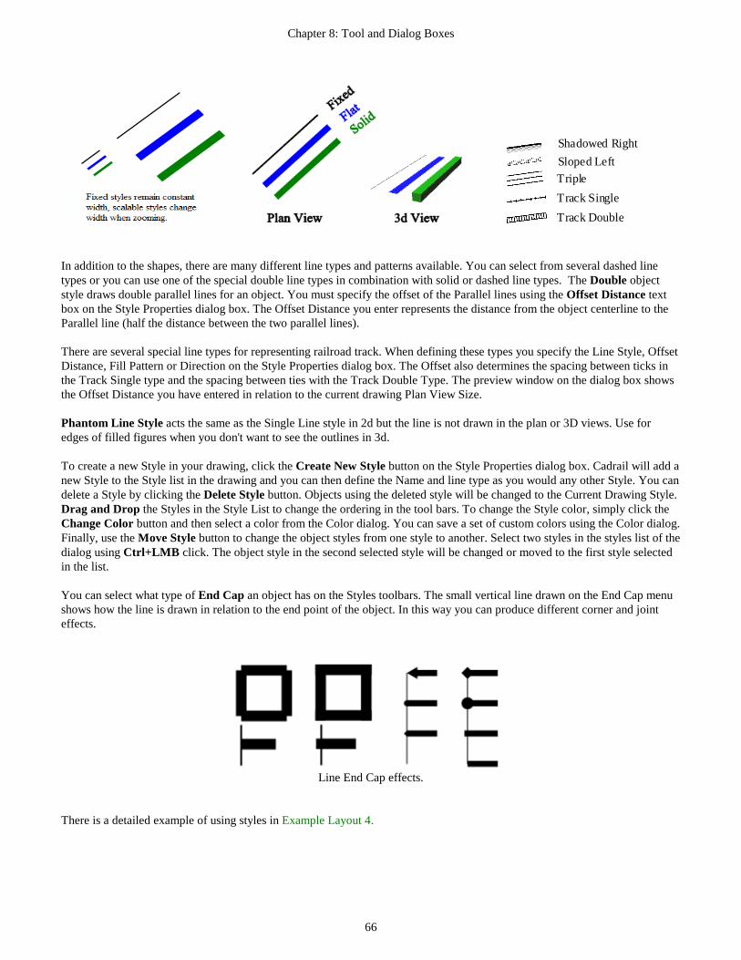
Chapter 8: Tool and Dialog Boxes
66
Shadowed Right
Sloped Left
Triple
Track Single
Track Double
In addition to the shapes, there are many different line types and patterns available. You can select from several dashed line types or you can use one of the special double line types in combination with solid or dashed line types. The Double object style draws double parallel lines for an object. You must specify the offset of the Parallel lines using the Offset Distance text box on the Style Properties dialog box. The Offset Distance you enter represents the distance from the object centerline to the Parallel line (half the distance between the two parallel lines). There are several special line types for representing railroad track. When defining these types you specify the Line Style, Offset Distance, Fill Pattern or Direction on the Style Properties dialog box. The Offset also determines the spacing between ticks in the Track Single type and the spacing between ties with the Track Double Type. The preview window on the dialog box shows the Offset Distance you have entered in relation to the current drawing Plan View Size. Phantom Line Style acts the same as the Single Line style in 2d but the line is not drawn in the plan or 3D views. Use for edges of filled figures when you don't want to see the outlines in 3d. To create a new Style in your drawing, click the Create New Style button on the Style Properties dialog box. Cadrail will add a new Style to the Style list in the drawing and you can then define the Name and line type as you would any other Style. You can delete a Style by clicking the Delete Style button. Objects using the deleted style will be changed to the Current Drawing Style. Drag and Drop the Styles in the Style List to change the ordering in the tool bars. To change the Style color, simply click the Change Color button and then select a color from the Color dialog. You can save a set of custom colors using the Color dialog. Finally, use the Move Style button to change the object styles from one style to another. Select two styles in the styles list of the dialog using Ctrl+LMB click. The object style in the second selected style will be changed or moved to the first style selected in the list. You can select what type of End Cap an object has on the Styles toolbars. The small vertical line drawn on the End Cap menu shows how the line is drawn in relation to the end point of the object. In this way you can produce different corner and joint effects.
Line End Cap effects.
There is a detailed example of using styles in Example Layout 4.

Chapter 8: Tool and Dialog Boxes
67
Drawing Manager Many useful functions are contained within the Drawing Manager on the right side of the Cadrail application window. At the top of the Drawing Manager are tabs to organize the functions. When you click a tab the Drawing Manager will show the features for the category. There is an Object tab where you can view and edit object data, a Properties Tab for setting Layer and Style Properties, and a Library Tab where you can open additional Cadrail drawings and then drag and drop the Figures into the current drawing Object Tab You will see three areas on the Drawing Manger when the Objects tab is selected. To see how they work, open the Tutor 3d.crw drawing located in you personal library folder on your computer. Next select the Objects Tab on the Drawing Manager at the right of the Cadrail application screen. Now select the Edit Freehand tool and click on the left arc of the figure 8 in the tutor3d drawing. After selecting the object a Preview drawing of the object is shown at the top of the Object Tab. In the center of the Objects Tab the Object Properties are shown in the Object Data Grid. See the illustration that follows.
Drawing Manager Objects Tab with library drawing Tutor3d.crw. Using the Object Data Grid After an object is selected in the Plan View or Drawing Tree, the object’s data is shown in the Drawing Manger Object Data Grid (ODG). Here you will see the object number, layer, style, coordinates, length, grade etc. The Object Data Grid is also accessed from the Plan View RMB Popup Toolbar .. Click an item in the right column of the Data Grid to change it. Depending on the object property type selected you may either edit the value in the grid cell or you are presented with a menu or dialog to choose the property. For objects you can change Layers and Styles or any other property. Figures let you set Fill Styles or set Elevations and Grades using the Profile dialog found on the RMB Popup Menu for the Object Data Grid. You can find more detailed descriptions of the Object Properties in the other parts of this manual.
Drawing Figures Tree
Object Data Grid
Preview
Objects Tab

Chapter 8: Tool and Dialog Boxes
68
The ODG cells use the same format to enter feet/inches as the numeric text boxes such as the Grid as described in other sections of the manual. You can enter feet and inches or decimal values. As you change geometry properties of a drawing object like lines or circles, the other properties will adjust and update. As you move the mouse pointer over geometry values the Tool Tip Help will appear with the values shown as feet and inches (when the drawing is set on feet or inch units). Using the Drawing Figures Treeview The Drawing Figures Tree is located at the bottom of the Drawing Manger Objects Tab. This view lists all the Figures in the current drawing in a Treeview. The Treeview is similar to that used on the Layer and Styles Properties Tab of the Drawing Manager previously described in this chapter. Select the Auto-Update button at the top of the Treeview to update the data as you edit the drawing. With large drawings it takes time to update the tree so you may want to turn off auto-updating and update manually using the Update button next to the Auto-Update button. When you expand the Treeview Branch for a Figure by clicking the plus sign at the left, the Objects that make up the Figure are listed and they are shown in the order they occur in the Figure Definition. As with the Layers Treeview, the Drawing Treeview allows you to Drag and Drop the Figures and Objects to arrange their order in the Figure. When you select an object in the Drawing Treeview it is highlighted in the Plan View drawing area and the Object Properties are shown in the Object Data Grid. This allows you to easily edit objects that are nested in complex Figures. In addition to editing Figures, you can use the Drawing Treeview to add objects to the current drawing by Dragging the Object from the Treeview and Dropping it into the Plan View drawing area. Finally, the Drawing Treeview has an RMB Popup Menu with items to Delete Figure Definitions and other tools. Properties Tab Click the Drawing Manger Properties Tab to show the drawing Layer and Styles toolbar. This toolbar operates the same as the Layer and Style Toolbar accessed on the Top Toolbar. See that section of the manual for additional information.
Drawing Manager - Properties Tab
Properties Tab
Layers Toolbar
Styles Toolbar
Object End Caps

Chapter 8: Tool and Dialog Boxes
69
Library Figures Tab You can open and show the Figures in a drawing using the Library Tab of the Drawing Manger. Once you open and drawing into the tool bar you can drag and drop the Figures into the current drawing in the Plan View.
Drawing Manager - Library Tab A step by step sample of using the Figures toolbox can be found in the Drawing Tutorial Example 1. See Also install Personal Drawing Library .
Opening a drawing into the Figures Toolbox Click the Open Figures Drawing button on the Figures Library Tab to open a Cadrail drawing and show all of the Figures in the toolbox. After the Open dialog appears, select a drawing. Cadrail will load a copy of all of the Figures from the selected drawing into the Figures toolbox (neither the original or current drawing is modified). To copy a Figure into your drawing, point to the Figure in the toolbox list and press the left mouse button down. While holding the button down, drag the figure into the drawing area to the approximate location for the Figure. Then, release the mouse button over the drawing area to copy the Figure into your current drawing. In other words, you drag a Figure from the toolbox list and drop it into the drawing.
Changing Properties of the new Figure When you copy a Figure into your drawing from the Figures toolbox it will maintain all of the properties the object had in the original drawing. If you have the Change Properties button selected on the toolbox, the new Figure will be given the properties that are currently set on the Layer and Styles Properties toolbox.
Click Open Figures Drawing button to load Figures.
Properties Option
Drag Border to Resize
Library Tab
Close Drawing Manager

Chapter 8: Tool and Dialog Boxes
70
Preferences Dialog Box You can specify default values for the various application and drawing properties on the Preferences dialog box. Activate the dialog by clicking the Options- Preferences item on the Main Menu bar. Near the top of the Preferences dialog box there are three Tabs that you can click to select various setups for your Drawing and the Cadrail program. Features involving the drawing setup will be saved with the drawing. So if you open the drawing on a different computer setup, you will still see the same drawing features. Program features that effect general Cadrail operation are saved with the Cadrail Program Setup. The saved Program Settings are applied each time you start Cadrail. Current Drawing Setup The Current Drawing Setup Tab on the Preferences Dialog is saved with your individual drawings. When you create an object, it will be assigned the default properties specified on the Drawing Preferences.
Drawing setup is changed on the Preferences dialog box.
Dimensional information is in Drawing Units. If you specify the Text to be 6 inches high, when you create new Text in the drawing it will be given that height in the drawing and it will scale up and down just like a line object does. The Drawing Position option should normally be set for Draw Figures Back to Front as defined with the Edit- Position- Move to Front/Back tool. The Foreground/Background Fill option is provided only for backward compatibility for Cadrail version 8 or before. New Drawing Template You can specify the drawing template that Cadrail will open whenever you create a new drawing using the New Drawing Template Tab on the Preferences Dialog box. If you elect to use the Default Template, .when you make a new drawing or when Cadrail starts up, Layers and Styles used in the drawing will be set to the default program values. If you would like to change these default values, you can simply create a drawing and set the Layers and Styles to what you want and then save that current drawing as the drawing template. Then when a new drawing is created it will simply be a copy of the Cadrail drawing that you saved as the template. All properties of the template drawing are copied including the objects. In this way you might draw a boarder and title block, save it as the template, and then with each new drawing you get your standard title sheet.

Chapter 8: Tool and Dialog Boxes
71
Specify a startup drawing template with the Preferences dialog. Cadrail Program Setup The Cadrail Preferences dialog box lets you activate features, select display colors and define the display font. You can activate the Preferences Dialog box by selecting Options- Cadrail Preferences from the Main Menu bar, or by clicking the Units button on the Bottom Tool Bar. There are several Tabs at the top of the dialog box that let you select a group of features. Click the Tab to see the related options. Click the Re-install Personal Drawing Library button to replace the Library files. When you exit the dialog the settings will be saved and applied the next time you start Cadrail.
Preferences Dialog with Program Setup Tab To change the color of screen display options, click the item in the list on the Program Setup Tab of the Preferences dialog box. Then click the specific color item on the Color dialog box that appears.

Chapter 8: Tool and Dialog Boxes
72
Select the Font you want to see for the drawing screen labels (such as the Grid Axis) by clicking the Font button on the Font Tab of the Preferences dialog box. You can have Cadrail save the drawing at the time interval you specify with the Auto-Save spin button. When the time interval has elapsed, Cadrail will automatically save the drawing after termination of any drawing tool. Select the *.BAK option on to create a backup copy of your drawing when the drawing is saved. Whenever you save your drawing the previous version will be copied in the source folder and renamed with the last three letters as BAK. The auto-save option saves the existing drawing file with its current name. You see the time of the last save in the file details. Auto-save is executed when the "cancel" state occurs such as selecting Cancel on the right mouse button popup menu or by completing a tool operation or by just selecting a new tool on the toolbar. Therefore autosave does not occur if the drawing has not changed or Cadrail is idle. When you use the .bak option a copy of the existing file is made in the same folder as the original before saving the newest version. Then the new version is saved as .crw. Therefore the first time you save a file no backup is made. When the file already exists on the drive then a .bak copy is made before saving the new version.. The Dimension Type allows you to specify how to display the distance shown for a Dimension Line. Some inadvertent conditions can require you to reset the personal application settings. There is an option for this in the menu item OPTIONS-PREFERENCES-Cadrail Setup Tab and check the item STARTUP WITH DEFAULT SETTINGS then click OK and restart Cadrail That will reset things back to the shipping defaults. The personal settings are saved in the windows setup so even if you un-install and install they may not be changed. If you need to delete your user settings, delete the Sandia Software folder C:\Documents and Settings\User\Local Settings\ApplicationData\Sandia_Software (exact path can differ with operating system version). Automatic Updates When you start Cadrail it will check for new updates from Sandia Software's web site. You can disable this feature using menu item OPTIONS – PREFERENCES -PROGRAM SETUP tab CHECK FOR UPDATES ON STARTUP. You can also check for updates manually using the menu item OPTIONS - CHECK FOR UPDATES. When the next version of Cadrail is available, you will be notified upon starting. When you update Cadrail, a complete installation package is downloaded from the internet that installs the update. New updates will create a new listing for the Cadrail update version in the Windows Control Panel - Uninstall Programs section. To un-install Cadrail you need to un-install each Cadrail version listed in the Windows Control Panel. The update installation is similar to the normal Cadrail installation. Download the file and run the installer by selecting Install on the update notification dialog.

Chapter 8: Tool and Dialog Boxes
73
Inputting Numbers with the Toolbars As you use Cadrail you will need to give it numeric values for dimensions and other things. There are several ways the tools allow you to enter a numeric value using a Text Box control. The Text Box is a standard Windows item where you click the mouse into the box to give it the Focus and then you type letters and numbers from the keyboard into the box. Cadrail takes this a step further by allowing you to use a special Format to enter numbers as either decimal values or as feet, inches, and fraction separated by spaces. Inputting a Numeric Value using a Text Box When you need to enter a number into Cadrail you will use a Text Box that allows several number formats such as Feet Inches and Fraction or Decimal value. Once you have typed the value into the Text Box you must tell Cadrail you are done by clicking the Enter button on the text box (you can also or press the Enter Key or for dialogs click the OK button). For some tools you just need to move the mouse pointer away from the box or click on another empty area of the application. For Example, to enter Feet, Inches, and Fraction into a Text Box you simply put a space between the values. You type 4 space 3 space 1/2 (where the space represents a blank space you type in) to represent 4 feet 3 and ½ inches or a decimal value of 4.2917 feet. You may also type in the decimal value 4.2917. If your drawing is in units of inches you just type in the Inches space Fraction. To enter an angle value you may enter the Degrees Minutes Seconds using spaces between the numbers. Tools like the Grid Increment on the Top Tool Bar will show two small buttons at the right of the Text Box. To enter the value
click the ̂ button. Get a Help box by clicking the ? button at the right of the text box (click again to hide the help). The help shows format examples and the current value you have entered. See the illustration.
Grid Increment Input Number Text Box with Popup Help shown. Input Toolbar Drawing Tools that require you to enter a numeric value will appear on the screen with various tools and options to let you input a specific values to Cadrail. The Input Toolbar is utilized to request a value from you. To enter the value(s) type in the corresponding Text Box(es) on the toolbar by clicking the box with the mouse pointer and then typing with the keyboard. The Input Toolbar allows you to convert feet, inches, and decimal drawing units as described previously in using Input Text Boxes.
Type the Value
Click to Enter the Value
Click to Show Help

Chapter 8: Tool and Dialog Boxes
74
Input Toolbar. When you are entering an angle with the Input Toolbar, you can elect to enter angles as decimal or Hours, Minutes, and Second degrees. Dimension Options The Dimension Options allow you to input an exact value for various object dimensions while you are drawing. When you select certain tools on the Drawing tool bar you will see the available Dimension buttons appear on the Bottom tool bar. For example, when you select the Line-Free Hand tool you will see the Length and Azimuth Dimension buttons.
The Dimension Options allow you to toggle the feature ON and OFF. To turn the feature on, click the button so it is highlighted and pressed down. To turn it off, click the button again. When you click the Dimension button on, a Text Box will appear to allow you to type the value for the Dimension. The value you enter will then be fixed and shown to the right of the button. When a Dimension Option is on, the Mouse Pointer will change (see Mouse Pointer in Chapter 1) to indicate the option that is active and the dimension will be applied when you create an object in the drawing. You draw with a tool normally and then Cadrail will substitute the Dimension value at the appropriate time. When a Dimension Option is Off, Cadrail will show the dimension value based on your current mouse position in the drawing. Every tool has different Dimension Options available. The available options will be shown on the Bottom tool bar after you have selected a drawing tool. The various Dimensions available include Length, Radius, Azimuth, Angle or Elevation. The options available for each tool are listed in the tool descriptions found in the Appendix.There is a detailed example of using the Dimension Options in the Tutor Example Layout 2. Object Number Input You may use the Object Number Input feature to specify an individual object while drawing instead of clicking on the object with the mouse. To specify an Object Number, use a drawing tool as you normally would. However, when you are asked to select an object, click the Edit- Input Object Number item on the Main Menu instead of clicking on the object in the drawing screen. When the Input Object dialog box appears, enter the Object Number. Cadrail will then use the object you entered in the drawing command. To see the Object Numbers on the screen, click the Object Number Display button at the right of the Cadrail application window.
Dimension Options

Chapter 8: Tool and Dialog Boxes
75
Specifying Mouse Pointer Coordinates With some drawing operations you may want to specify exact coordinates for the mouse position in the drawing instead of moving the mouse freehand. There are several options available in Cadrail that let you specify the mouse position with coordinates. You can enter X, Y, Z values for the Current Mouse Coordinates during any drawing operation by clicking the X, Y Coordinate display on the Bottom tool bar. Clicking the Bottom tool activates the Input Toolbar where you can enter values for the X, Y, and Z mouse coordinates. An example of entering coordinates can be found in the Drawing Tutorial Example Layout 2. The Change in X, Y Coordinates (Delta X, Y) for the mouse position can be activated by clicking the display on the Bottom tool bar. The X, Y values represent the distance to move the mouse in the drawing from the last point you set in the drawing. For example, if your last mouse click was at coordinate ( 10, 10) and you entered a change in the X direction of 5 drawing units and a change in the Y direction of -3, Cadrail will click the mouse at coordinate (15, 7) after you exit the Input Toolbar.
RMB Popup Toolbar The RMB (Right Mouse Button) Popup Toolbar is a smart tool that predicts which tools you need based on what you were doing when you opened the toolbar by clicking in the Plan View. Buttons shown on the Popup Toolbar will change depending on what Object is selected in the drawing area. If no object is selected, only the Cancel, Edit, Zoom, and Undo buttons are shown. When an object has been selected first using the Edit Freehand tool, additional buttons are shown like Delete, Copy, Change Properties, and Position. Furthermore, selecting a Figure shows tools related to Figure Objects. Simply click the RMB in the drawing Plan View to activate the RMB Popup toolbar. If you first select an object with the Edit-Freehand tool the toolbar will have features for that object type. You can choose the Edit Object button to show the Object Data Grid (ODG) below the Popup Toolbar Buttons. This ODG is the same as the one on the Drawing Manage Objects Tab. You can change object Layers and Styles, edit geometry, etc.
RMB Popup Toolbar with Optional Object Data Grid. You can Select a drawing object and open the RMB Popup Toolbar with one step by using Shift + RMB click on the object in the Plan View. To move the Popup Toolbar simply drag the Toolbar Top Header on the screen using the LMB. The Last Tool, Profile, and Clone tool buttons are only found on the RMB Toolbar.
: Last Tool : Clone Properties : Profile Dialog

Chapter 8: Tool and Dialog Boxes
76
Shape Builder Dialog Box Use the Shape Builder to create special shapes in your drawing. Activate the dialog using the menu OPTIONS-SHAPE BUILDER or clicking the SHAPE BUILDER button on the Labels tool bar. The dialog has TABS at the top that you click to create the various shapes.
Shape Builder Dialog Box.
CYLINDER TAB (Shape Builder) 1. Specify the Shape using the Dialog box. You can select any number of sides from 3 to 20 using the up/down arrows on the
dialog display. 2. Select the coordinate axis for the length of the shape using the drop-down list. 3. If you want the sides filled then select the Fill Sides option and specify the color. 4. Click the dimensions on the preview to specify the shape’s size in the Input Text Box. 5. Click the CREATE button on the dialog box. Cadrail will insert the yard at the center of the drawing.
TURNOUT BUILDER TAB (Shape Builder) 1. Select the location for the Turnout in the drawing. 2. After the Turnout Builder dialog box appears, click on each of the four dimensions for the Turnout. When you click on a
dimension, Input Toolbar will appear where you can enter the numerical value of the dimension. 3. After entering all four dimensions, click the CREATE button on the dialog box. Cadrail will insert the yard at the center of
the drawing.

Chapter 8: Tool and Dialog Boxes
77
YARD BUILDER TAB (Shape Builder)
1. Select the Number of Turnouts to add to the yard (not counting the first Turnout you clicked on in step 1) using the spin
button. 2. Select the Type of Turnout you want to use in the yard from the List of Turnouts at the bottom of the dialog box.
Optionally, open a different drawing to select a Turnout from by clicking the File Open button on the lower right of the dialog box.
3. You can elect to have Cadrail place the turnouts end to end to obtain minimum spacing between the yard tracks or you can enter the yard track offset between parallel yard tracks by clicking the offset value in the picture.
4. Optionally click the Length value on the picture to add Yard Lines. If you enter a value for Length, a Line will then be created at each Turnout.
5. Click the CREATE button on the dialog box. Cadrail will insert the yard at the center of the drawing.
Insert Picture
You can add a Picture object to your drawing by clicking the INSERT PICTURE button on the Top Tool bar. . . . . After clicking the File Open Dialog will appear where you can select the picture file you wish to insert into the drawing. You can select from JPG, GIF, BMP, PNG, and TIFF formats. After you select the file name, a second dialog is shown where you can input the scale width of the picture in the drawing. The horizontal width of the picture will be set to the distance you enter in the drawing scale. Once you have entered the scale width the Picture will be inserted at the center of the current drawing view window with the size you specified. After the Picture has been inserted you can use the Edit Freehand and other tools to move, rotate, and resize the object. To change the image for Picture Object in your drawing use the Drawing Manager Object Data Grid. See Figure Fill options for inserting a picture into a Figure. Cadrail’s Save Picture in Fence tool allows you to copy and save an area of the drawing screen. Pictures can also be shown inside the area of a Figure group of objects. See the Figures Chapter of this manual for details and how to use the Drawing Manager Object Data Grid. You can use the Picture Paint Dialog .to change image properties of your Pictures.
Picture Paint
You can change the brightness and other image properties with the Picture Paint dialog. Use the scrollbars to adjust the feature. Activate Picture Paint from the RMB Popup Toolbar ., In addition use the RMB Menus on the Drawing Manager Object Data Grid, or DM Figure Treeview (after first selecting a Picture).
New Turnout Figures New Yard Tracks

Chapter 8: Tool and Dialog Boxes
78
Using the Profile Dialog You can easily set elevations and stations for a Figure, Line, Arc, or Spiral with the Profile Dialog box.
Profile dialog box.
The Profile dialog allows you to enter elevations for both ends of a Figure or you can specify the elevation of one end along with a grade and Cadrail will calculate the other end. Show the Profile dialog by selecting an Object in the drawing area with the Edit Freehand tool on the Drawing Toolbar. Next click the Right Mouse Button (RMB) in the drawing area to show the Popup Toolbar. On the Menu select the Profile item to show the dialog. The Profile can also be shown using the RMB Popup Toolbars for the the Drawing Manager Object Data Grid or the Drawing Figures Treeview. A profile view of the Figure is shown with the Station and Elevation values in the linear scale diagram. The profile shows all elevations, lengths between stations, and grades. Simply type a value into any of the four text boxes on the dialog. The remaining values will automatically update as required. Of course, the Figure you edit must be a continuous alignment of connected objects or the numbers will not be valid. The sample shown here is one end of the figure eight drawn in the tutor example plan. The preview picture on the left side of the dialog box shows you end point 1 and 2. As you enter the elevations, Cadrail will update the grade on the dialog box. If you prefer, enter one elevation and a grade into the dialog box. Cadrail will calculate the opposite elevation for you, and update the dialog box. If a Figure has been selected, Cadrail will assign elevations to all the object end points in the figure. Cadrail will apply the grade that has been specified to each object in a Figure using the ordering that the objects occur in the Figure definition. A Figure must have matching end points (same x, y coordinate) or Cadrail can’t tell what direction in the alignment to assign end points. You may assign the same elevation to all points in a Figure by making Elevation 1 and 2 the same in the dialog box. Note: To minimize screen clutter, elevation labels are not shown for object end points with zero elevation. You can find a detailed example of using Stations and Elevations in the Drawing Tutorial Example Layout 3.

Chapter 8: Tool and Dialog Boxes
79
Importing, Exporting and Converting The File- Import and Export items on the Main menu bar let you save and open different types of File Formats To Open or Save another format:
1. Select the File menu item that corresponds to the type of operation you want. 2. Choose the name of the file in the File Open or File Save dialog box.
File Formats Cadrail saves your drawing using a special file format or language. Different file formats are normally distinguished for the user by the file name extension (three letters following the period in the name). Cadrail normally uses its own file format with the extension of CRW. Cadrail drawings are vector files. A vector file saves the coordinate geometry for each object. Then each object can be moved individually without affecting other objects. It can be the drawing resized and manipulated with no loss of information. On the other hand, .BMP, .GIF, .PNG and .JPG formats are BITMAP files. This mean it is map of the dots (pixels) in the image. The dots are similar to what you see in a newspaper print photo, but, much closer together. Each dot has a color and it is shown dot by dot on the computer screen. If you resize the image you will get distortion. Save your drawing background as a Windows Bitmap picture (bitmap) file using the Save Picture in Fence tool on the Drawing Toolbar. You can use Windows Paint (supplied with Windows) or other paint program to draw on a bitmap image. You can copy a selected Picture object to the Windows Clipboard using Edit – Copy to Windows Clipboard menu item. Once you have the image on the clipboard, you can paste the image into other programs that support bitmaps such as Windows Paint or Microsoft Word for Windows. To create a windows metafile format (.WMF) file, use the Save Picture in Fence tool and select the options to save file, then select the .WMF extension for the filename on the File Save dialog box. Cadrail does not print .PDF format directly. You can however install a PDF Printing utility that acts like a normal printer in Cadrail. The PDF software creates a PDF file instead of printing on a printer. There is free or low cost PDF Print Software available for this purpose.
DXF Format You may convert to the AutoCAD DXF vector format by importing (open and convert) or exporting (convert and save) the drawing. When you import a DXF file using the File-Import-Import DXF menu, Cadrail will convert the drawing to Cadrail's CRW format. The DXF format allows you to maintain layer information in programs that support this feature. When you export the Cadrail drawing, the units in the DXF file will be Engineering or Architectural Inches. Only the basic Cadrail objects are supported. Furthermore the treatment of Styles is different in AutoCAD. You should practice with a simple drawing. Consider other methods like printing to a PDF file. (requires PDF printer software) instead of DXF format. Merging Two Drawings You may merge an entire drawing into another using File-Import-Merge Cadrail on the Main Menu. When selected, the normal file open dialog will appear to allow you to select the drawing file you wish to merge into the drawing you are currently editing. You can select a single drawing or use the ctrl+ key to select multiple drawings. All the properties and coordinates of the files will remain unchanged. If you open a drawing file created in Cadrail versions 4 through 7 it will be automatically converted to Version 10 format . When you open a version 4 or 5 drawing, you will see the Convert dialog box that allows you to specify the units of the older

Chapter 8: Tool and Dialog Boxes
80
version drawing. Since Version 10 allows you to change units on the fly, you must first tell Cadrail the units of the older version file. The units you select will be shown on all grid or dimension displays. Once an earlier version of a drawing has been converted to version 10 format and saved, the earlier version of Cadrail will not be able to read the new file. Importing Layer and Style Properties Import Layers and Styles on the File menu of the Main Menu bar will allow you to add the Layer and Style definitions from another drawing into your current drawing. If the current drawing contains objects with Layers or Styles that do not exist in the imported drawing, the objects will be moved to Layer 0 or Style 0 in the current drawing. Personal Drawing Library Cadrail comes with track and other types of drawings that you can copy and use in your drawing. These library drawings are installed when you first start Cadrail. When you start the Cadrail application for the first time, you are given the option to install the Personal Drawing Librarys in your Personal Folder. If you accept installation the folder is named MyDocuments\Cadrail 10 Drawings (unless you specify a different folder name). You can re-install the library drawings anytime using the menu Optons - Preferences – Setup Tab and clicking the Click to re-install Personal Library button. This will replace the existing drawings if any so if you have edited them you need to make copy those before re-installing the Library. See the Appendix or more Library information.
Work Sheet The Work Sheet window gives you access to detailed coordinate and dimensional data about the objects in your drawing. To activate the Work Sheet, select Options-Work Sheet on the Main menu bar (or press the Ctrl+K shortcut key). There are two report types available on the Work Sheet: Select the report type using the TABS at the top of the dialog box. The lower half of the Work Sheet window includes a Spread Sheet Summary List of the information you generate. Once you have selected a report type, you may click the Show Report button to generate the Spread Sheet Summary. Materials Report Select the Materials Report type on the Work Sheet to generate a summary showing the total lengths of the objects in your drawing. A summary of the individual Figures is also produced.
Chapter 8: Tool and Dialog Boxes
81
Miscellaneous This section contains general information about Cadrail. Angle Units Angles may be entered as either degrees, minutes, seconds or as decimal degrees using the Input Toolbars. To use decimal units, simply enter the decimal value with a period (i.e. 45.5031). Distance Units You can work in units of inches, feet, meters, centimeters, or millimeters. Select the units you want to see at any time using the Preferences dialog box from the Options- Preferences menu. When entering numbers the Input Text Box allows you to enter decimal values or Feet Inches Fraction. Limits The maximum coordinate or number that Cadrail will accept is positive or negative 9,999,999. The maximum Plan View Width is 999,999. As you get more and more Objects in your drawing, it will take Cadrail longer to perform basic functions like Find and Redraw. This is normal with any CAD program. There is no limit to the total number of Objects, Layers or Styles you can have in your drawing other than the performance of your computer. Optimize Drawing Select this option on the Options menu of the Main Menu to remove the spaces left by all deleted objects and figures from your drawing. The object and figure numbers will change and the drawing file size will be smaller. In addition the drawing is scanned for corrupt figures and objects.
Save Current Window Settings You may save the position of the current windows you have open by selecting Options-Save Current Window Settings from the Main Menu bar. After saving, the next time you start up Cadrail the windows will be moved to their saved positions on the screen. Save Window Settings on Exit When Options-Save Window Settings is checked on the Main Menu, the position of the current Cadrail windows will be saved upon exiting the Cadrail application. The next time you start up Cadrail the windows will be moved to their saved positions on the screen. Trouble Shooting If you are having a problem with the Cadrail application operation, first look in the chapter titled Common Questions to see if your problem is listed. Then check the ReadMe.Txt file distributed with Cadrail for the latest information (you can view the file with Windows Notepad). If you are having problems running Cadrail on your system, try re-installing the program. Make sure you meet the minimum system requirements stated on the first page of the manual. Make sure you are not having a conflict with another application running in the background on your system such as an anti-virus program.

82
Chapter 9: Runrail Runrail is an operational simulation mode that allows you to run trains on your drawings. You may switch back and forth between Cadrail and Runrail by selecting the Runrail on the Top Tools Label tool bar. When in Runrail mode the Drawing Tool bar will show the Runrail tools.
Drawing Requirements The train in Runrail will run on any Line, Circle, or Spiral object in your drawing. Runrail will create track switches (turnouts) in your drawing using any Figures that have the Turnout Property on (see Figures Turnout Property). You can also create turnouts from Arcs with a connecting Tangent Line or two Arcs with a common end point. You do not have to define this type of turnout drawing as a Figure as long as the Line and/or Arcs are tangent to each other at a single common end point with the Arc. An object must only be used in one individual turnout in the drawing. If you use a single object as part of two different switches it will not work properly. Track alignment should be continuous (i.e. the end points between adjoining track objects must match) in order to run the train down the track. Just as with a real train, if there is a large gap in the track, the train will crash. Runrail requires matching end points to be within .01 units to find a connection. Gaps larger than this tolerance will be considered as a dead end track. One final drawing consideration is the number of objects you have in your drawing that represent things other than track. Although you may run trains on any object in any layer, basic search operations in Runrail are time dependent on the number of objects you have in your drawing. So if you have a lot of buildings, or the bench work, etc. in your drawing, Runrail will still have to determine if the train can run on these objects and this will begin to slow some program operations on large drawings. If you have many objects in the drawing, it will be helpful if you Freeze the Layers that do not contain track.
Runrail Toolbar Group
Switches, Un-Couple, Car Properties
Train Controls

Chapter 9: Runrail
83
Runrail Operations There are five basic train operations simulated in Runrail that will allow you to do most of what you can do with a real train: To start running the train: 1. Open a drawing 2. Select the Runrail tool group on the Drawing Tool bar. 3. Place the train at the location you want in the drawing. 4. Check that the Train Properties are set to the correct Length and Width for your model scale and drawing units. 5. Slide the Speed Scroll bar down to start the train moving. Detailed descriptions of additional tools follow.
Tutor 3d.crw drawing with Runrail train.
Place Train
You must Place the train on the track before you can run the train down the track:
1. Select the Place Train tool on the Runrail tool bar. 2. Click the mouse at the location in the drawing where you want to Place the Engine of the Train. Runrail will place
the engine and the cars on the track beginning at the point on the object you selected. Avoid placing the train on a switch.
. The engine may occupy any position within the cars of a train. If you wish to reverse the orientation of the train engine and cars with respect to the track, you may Point the train in the opposite direction.

Chapter 9: Runrail
84
Point Train To Point the Train in relation to the Engine: 1. Click the Point Train button on the Bottom tool bar. Runrail will re-draw the train facing the opposite direction
in relation to the engine (You must Place the train on the track before you can Point the Train).
Un-Couple Cars
After you have Placed a train on the track you may begin Un-coupling and Coupling the cars. You may split the train and arrange the engine and cars on the track in any order. (see Car Properties for more information). 1. Stop the train if it is running. 2. Select Un-Couple Cars from the Runrail Operation tool bar. 3. Move the mouse pointer to the joint between the cars or engine where you want to un-couple. 4. Click the left button on the mouse. Runrail will blink the cars to show the un-coupling. Cars won't move unless they are connected to the train that contains the Engine. Coupling cars back together again is performed by running the train into the cars you wish to couple with. Runrail will detect the overlap of the train with un-coupled cars and then re-couple the cars to the train.
Change Switch
Runrail searches for switches (Turnouts) in your drawing (see Drawing Requirements earlier in this chapter) when you switch to Runrail Mode. When a switch is found it is shown on the screen with a color highlight representing the current closed switch direction. The open object in the switch is a dark color. You may change any number of switches at any time. 1. Select Change Switch on the Runrail Operations tool bar. 2. Click the left mouse button on the switch you want to change.. Runrail will show the change by highlighting the
object the switch is set to. 3. Continue to click on additional switches or end the command by selecting another tool (or press the right mouse
button).
Reverse Train Direction Click the Reverse Direction Button on the Runrail tool bar to reverse the Train’s current direction of motion. In other words, this is the forward/reverse switch. The Direction the train moves on the track is not related to the position of the engine or the way the train is Pointing. You may reverse the train Direction at any time.

Chapter 9: Runrail
85
Find All Turnouts
Use Find All Trunouts after you edit the drawing to update the turnouts and other information Runrail needs. Click this button after editing or before running in Runrail.
Train Properties
The Train Properties dialog box is where you can organize the cars in the two trains. You can also specify the sizes of the cars. Activate the Train Properties dialog by clicking the button on the Runrail Tool bar.
Train Setup You can build a train full of cars in any order you like using the Train Tab on the Train Properties dialog. After a drawing is first created, a default Train is assembled and shown in the Train Properties dialog. This default train contains an Engine and 4 of the available cars. You can modify the Train makeup by selecting a car type in the list of available cars at the right of the dialog and then clicking Add Car to Train . The added car will then appear in the list on the left showing the Current Train cars and order. To remove a car, select it in the Current Train list and then click the Remove Car From Train button.
Train Properties Dialog Box.
If you want to start over with the default Train, click the Reset all Cars and Trains button. As you edit the objects in your drawing, the switches and train paths that have been previously saved with the drawing will be out of date. Click the Update all Switches and Paths button to have Cadrail reset things.

Chapter 9: Runrail
86
Car Setup Runrail lets you set any dimension for the Length of your rolling stock. on the Car Tab of the Train Properties dialog box. The coupler length may also be specified. Type the values in the text boxes on the dialog box.
Width
Car LengthCoupler Length
You should enter the real life car sizes for the Model Scale you use. Be sure to use the same units as the rest of your drawing. For example, a standard HO car size is around 6 inches or 0.5 feet. For this car you would enter a Car Length of 6 or 0.5 on the Car Properties dialog box. Width of the train is drawn by Cadrail as a simple ratio of the Length. The car properties that you specify are saved when you close the dialog. Speed Scrollbar The Speed Indicator on the Runrail tool bar shows the simulated speed of the train. Move the Speed Scroll bar to change the Speed. The speedometer units do not correspond to any scale representation of real or model trains.
Stop the Train Click the Stop the Train button on the Runrail Tool bar to stop the train from running. 3D Runrail You can view the train in the 3D View as you operate with Runrail. When the Runrail tool bar is active, a second Runrail tool bar will be visible on the 3D View tool bar. There are three different views available in 3D. First, the Bird’s Eye View (BEV) is just the normal view. Second is the Cab View where you look out at the track from the Cab of the Engine. Finally, you can look at the train from above with the Overhead View

87
Chapter 10: Railroad Design
Basic guidelines for drawing railroad layouts are presented in this chapter. However, one of the best ways to learn about railroad design is to pick up one of the well known railroad track planning books. These books provide a lot of information that we have not attempted to deal with in this manual. An excellent reference book for track planning is John Armstrong's "Track Planning for Realistic Operation". The first step in making a railroad track plan is to have some idea of the modeling scale you will use and what the overall dimensions of the layout will be. You should sketch some ideas on paper before moving to the computer (although you can sketch with Cadrail once you are familiar with the tools). Establish minimum criteria for your layout like the minimum curve radii, switch turnout angles and maximum grades. The type of rolling stock you will be using and methods of operation will play a factor in the design of the layout. For example, 18" minimum radius curves will be acceptable for short trains with small lengths of cars and engines. However, if you plan on running with the Big Boy locomotive pulling 30, 60' passenger cars you will need curves of 30" radius or larger (HO scale). What is the maximum grade you can use? If you are planning for one track to cross over another, there must be sufficient length of track to rise 3" to 4" (HO scale) without getting too steep for your models. Do you want a true reduction of scale from a real railroad (nearly impossible) or can you fudge a little in some cases (a 5 percent grade is rare in full scale railroads but you may need it in your model due to space limitations).
Model Railroad Scales and Clearances Before you draw a railroad alignment you need to establish minimum standards for curve radius, maximum grades and the offset distance between parallel sets of track.
Scale Ratio to Full Size
Ratio with HO Scale
Sharp Curve Radius (in.)
Normal Curve Radius (in.)
Broad Curve Radius (in.)
Z 1/220 0.396 7 9 12 N 1/160 0.544 9 12 15 TT 1/120 0.73 12 18 22 HO 1/87.1 1.00 18 24 36 OO 1/72 1.21 22 30 36 S 1/64 1.36 24 36 48 O 1/48 1.81 36 48 60 #1 1/32 2.72 48 66 84 G 1/22.5 3.17 54 76 86 G' 1/24 3.63 66 84 108
Model Railroad Sizes.

Chapter 10: Railroad Design
88
You will need to take extra caution when one track comes close to another. If there is insufficient clearance for two trains to pass, the cars will collide and derail. This is most critical around curves. When a railroad car is on a curve, the ends will be forced outside of the track width. Furthermore, the middle portion of the car is forced inside of the track. As the rolling stock increases in length, the offset between curves becomes more critical.
Scale Curves (in.) Straight (in.) N 1.6 1.0 TT 2.3 1.3 HO 3 1.8 S 4.5 2.5 O 6 3.5
Minimum clearances.
Advanced Railroad Drawing Techniques One way to create a railroad layout is to first draw all the outside dimensions or control objects (such as the outline of the room). Once the control objects are located correctly on the drawing, you can begin to fill in around them with the track. Use different drawing layers for each major group of objects if you want. Place the major curves of your layout first. For example, say you have drawn the outside of the room and your best guess for the outline of the bench work. You know the train will have to turn 90 degrees at one corner of the layout. Place a circle in this corner drawn to the radius that you think you need. Continue placing circular arcs in all the corners of the main line. You don't have to worry about the exact orientation at first because you will connect and trim the circles with straight lines later.
Bench work Outline
Major Circular Curves
Straight Tangents
Room Outline1.
2.
3.
4.
You should decide where your major yard ladders and sidings will be located early in your layout design. Use some of the library figures to copy a yard or two into your drawing. Drag these around to the locations you have in mind. Once the critical curves, yards and other obstacles have been located on the drawing, begin connecting things with straight lines. You will probably prefer to use broad curves to connect different areas on the layout (instead of straight lines). You can always tweak these connections for better effect at a later time. To locate smaller sidings, first locate the straight track. Then, add the branch line switch by dividing the main line and inserting a switch figure. You may prefer to just “rough in” the switch PI at first with straight sections until you know exactly where you want it, then add the exact switch figure later.

Chapter 10: Railroad Design
89
Constructing Tangent Lines There are 7 drawing tools to help make the connection between lines and circular curves: Line - Tangent Circle - Tangent Line - Between Circles Arc Fillet Line - Circle to Point Edit - Align A tangent line can be defined with a radius line through the circle radius point and the point where the circle connects with the tangent line (PC or PT). The angle between this radius line and a tangent line is always 90 degrees (a square corner ). At a 90 degree angle from the radius point, a tangent line provides the smoothest possible transition from a circular curve to a line. This line is a Tangent line by definition. You should note that, even though a tangent line is the best direct connection to a circular curve, if you want a truly uniform transition, a spiral easement should be applied between the curve and the line. Sometimes it is easy to create the tangent lines for a circular arc first, then see what radius circular arc can fit into the existing tangent lines. For example, if you have a 90 degree corner on your layout, and you have already drawn the edge of the bench work as two straight lines, you can use the Edit-Offset Object tool to create two parallel tangents in the corner, then use Arc Fillet to fit a circle to the new tangent lines.
2. Fit circular arc using Circle-Between Tangents
1. Create Tangent Lines
3. Trim Line ends using Edit-Trim (skip this step if Auto-Trim was ON).
using Edit-Offset
Reverse ( S-shaped ) Curves To make a reverse curve, first create three tangent lines, then fit in circular arcs or spirals with the Arc Fillet command. Or use the Circle - Line to Arc tool.

Chapter 10: Railroad Design
90
Compound Curves Use the Circle-Tangent Arc tool in combination with the Get End option to connect two circular arcs into a compound curve.
PC
PCC
PT
Use Align to match end pointsbetween two objects
c1 c2
r1
r2
and rotate tangentially
Curves for Loops To create a curve for a loop, first use the Arc Fillet tool to fit an arc to two tangent lines. Then use the Circle-Reverse tool to get the large side of the arc.
Circle-Between Tangents
Circle-Reverse
Curved Easements You can “ease” from a straight into a sharp curve using a large radius compound curve transition (or you can use a Spiral).
Large Radius Transition Curve
Creating uniform Angles You can use the Point - Distance/Azimuth or Distance/Angle tools to create precise angles repeatedly.

Chapter 10: Railroad Design
91
Bisecting Angles Create temporary objects in your drawing to construct more complex shapes.
1. Use Circle-Between Tangents to
make circular arc between
2. Use Point-at Radius to create a Point at the Circle radius
3. Use Line - Between End Points to create a
Line that is half of the angle
two tangent Lines
Double Track (Parallel lines) Cadrail offers two methods for making parallel lines. These can represent the two rails or the centerline of two main line tracks. The first method of creating parallel lines is to use the Edit-Offset tool on the Drawing tool bar. If you are drawing the rails, you would Offset the centerline on each side by half the distance between the rails. The second way to make parallel lines is to use the Parallel object style on the Layer and Styles Properties toolbox. The Parallel style causes Cadrail to draw two lines for the object on each side of the centerline. The Spiral Helix Stack circular arcs to make a circular helix that spirals in elevation. If several levels are planned use irregular angle sections (such as 170 degrees) so the end points are not all on top of each other to make editing easier.
1. Create two matching 180
degree circular arcs
with Angle Dimension Option.
using Circle - PC to Radius action
2. Copy the arcs for the desired
3. Define the arcs into a figure,
in the proper order.
1
2
3
4
number of levels.1
234
4. Move the arcs together usingAlign to match end points.
5. Use the Object Editor tool
to assign end point elevations to the Figure
at the desired grade.

Chapter 10: Railroad Design
92
Vertical Helix in 3D
Spiral Easements Sometimes you can create a circular curve, and then add spirals.
3. Use Edit-Extend to make
1. Use Circle - Between Tanents
2. Offset the Circle
4. Fit Spiral to tangent Line with
Spiral - Fit to Tangent drawing tool
to fit circular arc to tangent Lines
space for the Spiral
If you offset the tangent Lines, the Circular curve does not move.
3. Use Edit-Extend to make
1. Use Circle-Between Tangentsto fit circular arc to tangent Lines
2. Offset the tangent Lines
4. Fit Spiral to tangent Line with
Spiral-Between Tangents tool
to make space for the Spiral
space for the Spiral

Chapter 10: Railroad Design
93
Working with Elevations Draw your layout in three dimensions ( X, Y, Z ) to check that your grades and crossovers are adequate. Cadrail allows you to define a Z coordinate or Elevation for the object end points in your drawing. Locate some portion of your plan which will be the minimum elevation. This can be the lowest elevation of the table top, the elevation of the floor or any other arbitrary point you like. The main thing to consider is ease of use. If you pick some point on your layout and call this elevation zero, this may be the simplest method. First define the alignment into a Figure definition. Then use the Profile Dialog tools to calculate end point elevations along the alignment. Cadrail will calculate the elevations along the Figure based on either the elevation at each end of the Figure or the elevation of one end and the grade. Be sure the objects in the Figure are defined in the proper order and that all the end points match exactly. Once you have assigned elevations to the object end points, you may see the elevations in the Side views or in the 3D view of Cadrail. You may generate detailed X, Y, and Z coordinates at any spacing along the objects in your drawing using the Work Sheet Layout Report. You can draw and assign elevation to anything in your drawing. It does not have to be track (Cadrail does not know what the objects you draw represent in real life). You can give individual objects elevations or all the objects in a Figure. Therefore, you can add lines to your drawing to represent scenery contours and give these contour lines elevations. If the contours are close enough together, you can see what your mountains will look like in the 3D view. Use elevations to check the clearance at crossovers (bridges) for the train to pass beneath. Check that the grade produced by creating a rise at a bridge is not too steep for your models. A 4 percent grade is about the steepest most models can climb. Be sure to leave enough clearance at the crossover for the thickness of the bridge, the height of the cars and the height of the rails. In HO scale this requires from 3 to 4 inches of clearance. Building Your Layout Once you have drawn a perfect layout, you will still have to build it. This is where you can really put CAD to work or waste all the time you put into it. Keep in mind that you may absorb small errors when you build the layout. So, don’t spend so much time making accurate drawings of your layout that you never have any fun building and operating it. However, you must build the layout well enough that all that accuracy in your drawing really represents the full size model. One of the easiest ways to transfer your drawing onto the bench work is to make a full size printout and somehow trace through the paper or even lay the track on top of the paper. However, for large layouts this may become impractical due to the large numbers of little pieces of paper required. Furthermore, you may loose accuracy if you are not careful about taping all that paper together. You should establish your drawing coordinate system on your bench work to enable you to use the power of CAD. This simply amounts to making an X and Y axis baseline on the bench work. If you are clever, you should be able to make one of your main bench work edges (or even the walls of the room) into the baseline. You may wish to draw this in your drawing (if its not there already). Now whenever you use a printout or coordinates to locate something on the bench work, keep “checking in” to the baseline to make sure you haven’t slipped something by a small amount. When taping paper sections together, be sure to measure across several pieces of paper to check the overlap at the edges. In other words, if the distance of that yard ladder is 4.21 feet in Cadrail, measure one continuous length across several papers taped together to make sure it’s 4.21 feet in real life while you are taping it all together.

Chapter 10: Railroad Design
94
How to Draw Railroad Switches (Turnouts) Model railroad switches differ in two ways. First, the sharpness of the angle changes with the type of switch. Second, track length differs between type and scale of switch.
Switch Angle Ratio Angle in Degrees Snap 1" in 3" 18 No. 4 1" in 4" 14.25 No. 5 1" in 5" 11.31 No. 6 1" in 6" 9.5
The switch figures in the Cadrail libraries have been drawn as three straight lines with the proper angle at the PI. This complies with the requirements for setting the Figure Turnout property (see Figures, Turnout property). Then, when the Turnout property is set, you can use the Figure with the Shape Builder dialog (Options menu). You may represent your switches and track work any way you want (however you must follow the Turnout rules to set the Turnout property and use the Figure Turnout tools). Draw both rails if you want, or add the switch machine outlines. You can draw the switch with two lines and a circular curve. This is a best case representation of an actual switch. The most important thing is simply the angle of the switch and the ends of the track. What happens in between is not as important. You should purchase some of the manufacturer's switches that you plan to use. Printout any switch figures you make to full size and lay the actual switch on top to check what you have drawn. Once you have a prototype switch to work from, look at how the branch line is made. Note that, with most scales, it is not a perfect curve. Most switches have short sections of straight track on the curved (or turnout) side and through the switch points. Always keep in mind that in relation to your overall layout, what is important is how each switch fits together with the rest of the track. All the little details in between the ends of the switch are not important. You can make life a lot easier if you leave these un-important details out of your drawing so they won’t get in the way. The distance from the PI to the frog of the switch is termed the P.I.F. This distance is important when hand laying the track. But if you are using manufactured switches it is not important. Keep in mind that a manufactured switch may call itself a No. 4, but it may not have this exact angle at the PI.
No. 4 P.I.F. (in.) No. 6 P.I.F. (in.) N 1.312 1.969 TT 1.875 2.812 HO 2.625 3.938 S 3.5 5.25 O 5.0 7.5
PI to Frog Values
P.I.
P.I.F.
Frog
Small straight section
varies with manufacturer
Rail Ends
Switch Angle
When you use manufactured switches, the only critical factors in your drawing are the rail ends and the switch angle.

Chapter 10: Railroad Design
95
Drawing a Turnout The easiest way to draw a Turnout is to use the Shape Builder tool (Options menu). With the Turnout Builder tab you simply enter the actual dimensions into a dialog box and Cadrail will draw the Turnout Figure for you (See Figures, Turnouts). To draw a switch using an arc, follow this procedure: 1. Locate the rail ends for the straight leg of the switch (Line A-B in the following sketch). Use the length dimension option to
draw a Line for the straight leg with the length you measure from the real thing. Try to be accurate to within 1/32 of an inch. Use a good steel ruler to measure and be sure it is accurate. You may find that Cadrail prints more accurately than your ruler is marked so watch for small discrepancies.
2. Produce the turnout leg at the proper angle. Measure the turnout angle carefully with a large diameter protractor. This is the most likely chance for error. Try to measure within half of a degree. If what you measure is within half a degree of the theoretical switch angle (as listed in the previous table, i.e. No. 4 = 14.25 deg), use the theoretical angle value. Create the turnout leg with the Circle-Tangent command using the Angle Dimension option and Get End at end point B on the Line. Trial and error may be required with different radii to produce an Arc with a tangent that passes through end point C. Start with the equivalent radius from the following table.
3. Locate the rail ends at the turnout side of the switch. Create a Line tangent to the Arc with the Line-Tangent tool and Get End. Make a printout to check what your doing. You may need to adjust the Arc radius and tangent Line length several times before the printout matches the actual switch. The exact radius of the curve is not important, but make sure you have the proper angle. Finally, make sure the endpoint of the Line and Arc match exactly at end point B so that Runrail will operate properly.
4. Add a separate Line to reach beyond point B if required.
witch N HO S O 4 16 28 40 50 6 30 40 60 100 8 60 100 150 200
Equivalent Switch Radii (approximate) Be sure to make full size printouts of your switch as you are working to check what you are doing at each step. Make sure the end of the curved section matches the end of the straight leg at point B (see sketch) if you plan on operating Runrail on the switch.
A
C
B
Switch Angle
Arc at Angle, Radius

Chapter 10: Railroad Design
96
How to Draw Railroad Yards Railroad yards consist of a series of switches (Turnouts) stacked together with long sections of yard tracks on each switch. The easiest way to draw a yard is to use the Shape Builder (Options menu). The Yard Builder lets you specify track spacing and number of turnouts in a yard by simply entering the dimensions into a dialog box and then Cadrail will create the drawing for you. If you want to draw complex yard arrangements that the Yard Builder tool does not support, there are several additional Figure Turnout tools that will help. Drawing a Yard Ladder 1. Place the first base Turnout on the main line (use Figure- Insert Turnout tool or Edit - Align tool). 2. Use the Edit-Offset Object tool to make a parallel yard line by offsetting the main line.
2. Offset Main Line
1. Place Turnout & Main Line
3. Use the Figure - Turnout Ladder tool to place a new Turnout at the intersection of the base Turnout leg with the yard line. 4. Repeat steps 2 and 3 until you have all the Turnouts you need in the yard. 5. Make the final yard track by offsetting the last yard line and then using the Figure - Connect Turnout tool to create an arc
from the end of the Turnout to the final yard track.
3. TurnoutLadder tool
5. Connect Turnout tool4. TurnoutLadder tool
Squaring off a Yard 1. Draw a temporary line perpendicular to one of the yards lines where you want the yard to end. Use Get End if needed. 2. Use the Edit Extend tool in combination with the Extend to Object option (press the <Shift> key down and click on an
object with the mouse) to extend yard each line to the temporary perpendicular line.
1. Line - Perpendicular
2. Extend to Object

Chapter 10: Railroad Design
97
Placing a Turnout on a Yard Line Use the points of intersection (PI) to locate turnouts on yard lines: 1. Create the yard line PI by extending (or intersecting) the yard line to the projection of the line where the turnout will be
located. 2. Use the Align tool to place the Turnout PI on the yard line PI.
2. Align new Turnout at PI.
1. Create yard line Pointof Intersection (PI)
How to Draw a Siding The easiest way to draw a track siding is to use the Figure - Connect Turnout tool as described in the previous section on drawing yards. Siding using CAD: 1. Draw a Line in the drawing that is the length of the siding you want. Offset the Line by the centerline track spacing. 2. Copy a switch onto the end of one of the lines with the turnout facing to the other siding. 3. Create a Tangent Line from the end of the Arc on the switch.
1. Create Offset Lines2. Copy and Align aswitch to the end of theLine
3. Create aTangent Linefrom the turnout
4. Use the Arc Fillet tool to create a reverse Arc between the Tangent on the switch and the opposite siding Line. Use the
Dimension Option-Radius to set a fixed radius for the Arc, or use Get End to match the arc to the end of the switch. Once you have one end of a siding drawn, you can create any combination of yard and siding shapes.
4. Create Arc-BetweenTangents
5. Divide Tangents atthe Arc End Points.

Chapter 10: Railroad Design
98
How to Draw a Crossover The easiest way to draw a track crossover is to use the Figures - Crossover Turnouts tool as described in the Figure tools section of the Appendix. To create a typical switch crossover with CAD tools: 1. Create a line. 2. Offset the line by the spacing desired. 3. Align a switch to the end of one line with the turnout side pointing to the second line. Align the opposite hand switch to the
end of the second line. You should now have two switches with the turnout sides pointing to the center of a double crossover.
4. Use the Line Tangent tool to create a line from the end of the turnout side of the two switches such that you have the intersection of the X formed by the two new lines.
5. Use the Edit - Divide at Intersection tool to divide the lines at the intersection of the X, this creates the short line from the end of the switch to the intersection point. This is the magic intersection point you need and it is exact.
2. Offset Line
3. Align switches to end of Lines
4. Create two Tangent Lines
5. Intersect Tangent lines for Crossover Point 1. Create a Line
6. Copy the short line made in step 5 and then align it at the intersection point. 7. Copy, Flip and Align another switch to the end of the Line from the crossover intersection point. Now you have all the
parts to make any arrangement of crossovers
6. Copy Line section to crossover Point
7. Copy, Flip & Align Switch
8. If you plan on using Runrail on a full crossover you should delete the short lines forming the intersection point X and replace with single lines between the ends of two opposite switches. This lets Runrail know where to go at the X.

Chapter 10: Railroad Design
99
Drawing Artwork One thing that seems to get lost in the transition from drawing with pencil and paper to drawing with the computer is the ability to then add fine details that make a good drawing a work of art. CAD makes it easy to make complex and accurate shapes. However you must still work a little more to add that artistic touch. As with pencil and paper, CAD artwork takes creative thinking and a little practice. Cadrail has many options and features that let you add some of the fine details you need to start bringing your drawing to life. Line styles are one of the most valuable tools you have for adding detail. Using the Properties tool bar you can give the objects in your drawing many types of line styles. You can use one of the track lines styles for your track. Use dotted lines for hidden details. Filled Figures can represent roadways, water, or fields. Vary the line widths to create shadow effects around bench work and buildings. Add sloped lines to represent cuts and fills around the track or slopes on hills and streams. As you add 3d contours with the Figure - Polyline tool you can begin to see the terrain.
Double TrackLine Style
Figure-PolylineContours
Trees &Buildings
Sloped LineStyle
Filled Figures
Line Widths

100
Chapter 11: Common Questions Common issues that you may experience are addressed in this section. Be sure to visit our web site Cadrail.com for the latest.
Basic Drawing Questions
After I create an object (or copy a Figure from the Figure toolbox), it disappears from the screen and then Cadrail can't find it anymore.
When you create an object, it is assigned the Layer property that is currently set on the Layer and Styles Properties tool bar (on the Top tool bar). If you do not have the Layer Visible property turned ON on the Layer and Styles toolbox, it will not be visible on the screen and Cadrail will not operate on that object (Cadrail draws the object when first created but will not draw it in subsequent Redraws).
When I drop a Figure into my drawing from the Figures toolbox it is not given the Layer I want…
Select the Current Properties option on the Figures toolbox. Then when you copy a Figure from the toolbox it will be assigned the Layer and Style that you currently have set on the Properties toolbox.
You can change the Layers of all objects in a Figure after you copy it to your drawing using the Edit – Change Properties tool.
When I create an object, it jumps to a different size than what it should have been based on where I clicked on the screen.
Make sure that the Dimension Options are OFF on the Drawing Tool bar. These options allow you to create objects using the dimension you enter. You must be sure they are OFF (not selected) to draw objects using the locations where you click on the screen. When a Dimension Option is ON, the mouse pointer changes shape (from the standard arrow or cross) to indicate that feature is active.
Cadrail cannot find the object I want when I click on it.
There are several conditions that may cause this behavior. You may have the drawing Layer turned off or Frozen on the Layer and Styles toolbox. Then, even though the object is visible on the screen, Cadrail will not find or operate on the objects in that layer. Turn the object Layer ON and the Freeze OFF. You may have several objects on top of each other in the drawing. You can use the Input Object Number function on the Edit menu to manually enter an object number during any command that requires Cadrail to find an object. Some objects are difficult for Cadrail to locate due to geometry problems. If you have the Snap On and set to a large increment, when you click the mouse to indicate what object you want, the snap moves your click coordinates so far from the object that Cadrail can not find it. Turn the snap off and try again.
How long should my spirals be?
A good rule of thumb for spiral length is to use at least two times the length of your railroad cars.

Chapter 11: Common Questions
101
How do I create my own Figure Library?
You can Load any drawing into the Figures toolbox and use the drawing Figures in any other drawing. Track Figures supplied with Cadrail are just like any other Figure that you create. You can open the library drawings and edit them as you would any drawing. Open a sample track library and look at the Figures. To make your own library you just draw and define your Figures, save the drawing file, and then load that drawing into the Figures toolbox.
When I make a Filled Figure the pattern is irregular…
You must define the objects in a Filled Figure definition in a clockwise direction around the perimeter of the fill. See the section of this manual on Filled Figures for more information.
Runrail won’t work on my drawing…
The objects that you are using as track for Runrail must connect end to end or the train will assume this is a dead end track. The end points between connected objects must match within the tolerance set in the Runrail Properties dialog. After you edit your drawing you must select Find all Turnouts on the Runrail drawing tool group after editing. This allows Cadrail to update the drawing when you are done editing. - You may have a problem from two objects on top of each other in your drawing. You may only see one object on the screen, but, there is a second object underneath the first so Runrail is stopping on that object. You may have a very short object in the drawing you are not seeing but Runrail is stopping at that object. Turn on the Object Numbers and End Points on the Display Options to look for problem objects along the alignment. Make sure that no objects are used in more than one switch. If you have an object that is part of two switches it will not work properly.
I copied the Cadrail folder to another computer and now I get the message "Cadrail License File could not be found" when try to run the copy of Cadrail.
You can not just copy the Cadrail Program folder to another computer and run Cadrail. Cadrail must be installed by running the original setup program so it can setup Windows properly. You need to install Cadrail from your disc or the original file you downloaded.

Chapter 11: Common Questions
102
Setup Program Questions
Message “Can’t find Setup.Exe” or “Device Unavailable” when running setup. This message occurs when Windows can not find the Setup program on the distribution disc. Make sure you are typing the correct drive letter when giving the setup command. For example, if your disc drive is called drive D on your system, you
should type d:setup on the Windows Run command line. Verify that the distribution disc is readable by listing its files with Windows Explorer or similar program. Try to copy all the files to your hard drive. Try another computer. If the disc was damaged during shipment, call Technical Support for a replacement. Try using Windows Explorer to launch the Setup program (double click SETUP.EXE in the file listing of the distribution disk).
Message "File Name out of date" when running setup or starting Cadrail.
You may have older duplicate copies of the file named in the message installed on your system. If these are in memory during setup or prior to starting Cadrail this message may occur (if they use older/newer versions of the files from those on the Cadrail distribution disk). Make sure no other programs are running during Setup (you may have to restart Windows to completely remove the programs from memory). Search your entire hard drive for duplicate copies of the file named in any messages. Rename the file temporarily and then try installing Cadrail again.
I downloaded Cadrail from the internet and when I run the downloaded file it starts XXX program, not Cadrail Setup (or possibly gives a goofy error message).
Download the file into an empty folder on your system and run the file from that empty folder. If you download to your Windows internet download folder or the Windows desktop you may get many different setup program parts mixed together in those folders. So, when you try to run the Cadrail installation some other program that has been installed from in that download folder starts running.
Setup Program gives Cannot Continue message. If Cadrail is already installed on your system and you attempt to re-install the software, you may get an error message from the installation program saying that the installation can not continue and then a log file address for more details. This simply means Cadrail is already installed. On most systems, if Cadrail is already installed, you will get a dialog box (instead of the error message) asking you what you want to do: Repair Cadrail or Un-install Cadrail. On some systems you may get an error message instead of the dialog. If you really need to re-install Cadrail, just un-install it using Windows Control Panel and then re-install. If you downloaded Cadrail on the Internet and purchased the additional DVD/Manual, you do not need to re-install Cadrail from the disc. The additional drawings on the disc are not installed during the installation. This is by design. If you want them copied to your system from the disc you will need to do that manually (use Windows File Explorer to copy the DRAWINGS folder on the disc to your hard drive).
I have a new PC/Vista 64-bit system, when I attempt to install dotnetfx.exe, I get a error message that it's not for 64-bit operating systems.
You do not need to install the Microsoft .NET platform or the DirectX 9c with the Vista operating system as these are already included with Vista 32 or 64 bit. Just install the Cadrail program. Cadrail runs in 32 bit mode on 64 bit systems.

Chapter 11: Common Questions
103
When I start Cadrail the window is minimized in the task bar. You may have saved the application window as minimized. Click the Right Mouse Button on the Cadrail task bar icon and select Maximize. Cadrail should open onto the screen. Set Cadrail how you like it and then select the menu item OPTIONS – SAVE CURRENT SETTINGS.
My tool boxes will not move correctly or the 3d window is off the screen. Some inadvertent conditions can require you to reset the personal application settings. There is an option for this in the menu item OPTIONS-PREFERENCES-Cadrail Setup Tab and check the item STARTUP WITH DEFAULT SETTINGS then click OK and restart Cadrail That will reset things back to the shipping defaults. The personal settings are saved in the windows setup so even if you un-install and install they may not be changed. Finally you may need to delete your user settings by deleting the Sandia Software folder C:\Documents and Settings\User\Local Settings\ApplicationData\Sandia_Software (exact path can differ with operating system version).
Converting from Earlier Versions of Cadrail
When I open my older version Cadrail drawing in the new Version 10, all I see on the screen is a little dot.
There may be some giant objects in the old drawing that you did not realize were there. For example, you may have made a line by accident that is 9999999 feet long and you don't see the object in Version 5. When you open the drawing in version 10, Cadrail uses the Show All Objects feature and then you don't see anything on the screen because the view is so big. Turn on the object labels display and then zoom in on the "dots", that is where the drawing is at a large scale and more will be visible when you zoom. To correct the problem, delete the giant objects. Use the menu item Edit - Input Object Number with the Delete tool if you cant click on the object(s) to select it.
I'm having difficulty seeing the drawings I create and print in Cadrail 10. The lines are much too thin and faint. I printed a drawing I created in Cadrail 8 from Cadrail 8 and it came out OK.
Cadrail 9 and 10 have a new scalable line style. It is described in Chapter 8: Defining Style Properties. You may need to adjust the widths for some of your version 8 drawing line styles (Layer and Styles Properties tool bar click edit styles). You can choose the fixed width style as in version 8 and set a number of pixels for the width, or choose the scalable style and define a drawing width for the line style that scales up and down with the drawing. For example you can make a scalable line style that is 6" inches wide and use a single line to draw a wall 6" wide in your drawing. This width gets bigger and smaller on the screen with the rest of the drawing as you zoom in and out. Check out chapter 12 for more on the new features.
When I open my drawing all I see is a small dot on the screen.
You may have a giant object in the drawing that is making the view size enormous so all the objects are small. Turn on object labels and then zoom in on the "dots", that is the drawing at its small scale and will show up when you zoom into it. Try to delete the giant objects. Use the menu item Edit - Input Object Number with Delete tool if you cant click on it to delete it (or them you may have several). If you can make a fence around the good part of the drawing, create a figure and copy it to a new drawing, leaving the giant or bad objects behind.

Chapter 11: Common Questions
104
Printing Problems
Cadrail did not print my drawing correctly... Try printing some of the sample library plans. If you can print the sample plans, but not your drawing, then the problem exists in your drawing. Make sure that your Windows Printer driver is the correct one for the Printer you are using and that you have selected the proper paper size. Contact the Printer manufacturer to see if an updated Printer driver is available. Some printers give an option in the Printer Setup to print as RASTER or HPGL, use the HPGL setting for best results. Try turning off the Grid and all Display Labels. Turn off the Heading and Border options on the Print dialog box. Try turning Layers off one at a time to see if you can isolate the problem. You may have created a very large object in your drawing that you don’t see in your view window. Use Show All Objects on the Top Tool bar menu bar to have Cadrail show all the objects in your drawing. Look for any objects that are very big compared to your drawing objects (make sure you have all Layers turned ON in the Properties toolbox and turn on the object numbers and end points on the Display dialog box to help see objects). Delete any of these bad objects. If you can’t click on an object, use the Delete in Fence tool or the Input Object Number option. Caution: your good drawing objects may only appear as a little dot if you are at a big view size. Don't delete your good objects by mistake.
The lines on my printout are fuzzy, too light or missing… Your black and white printer may emulate colors using gray scale shading. The colors for the layers in your drawing will be printed in different shades of gray. Experiment by printing lines of each layer and line style to see the results produced by your printer. Some ink jet printers do not print red or light gray very well, try it and see. You may need to change gray to black etc.
When I print, I get multiple pages and the drawing is the wrong size. You must set the print scale and number of pages to print using the Print dialog box. Each page is shown in the preview window as reversed colored boxes superimposed over the drawing. The size of the drawing as printed on the pages will depend on the current Page Scale you have selected on the Print dialog box. If your current page scale is very small, you may not see the print pages in the preview window because they cover such a small area of the drawing. You may increase or decrease the rows and columns of pages to print by dragging the page outline handles or by using the number of pages options. See the Print Drawing chapter for more.
I don't see the Grid lines on my printout... By default, the Grid lines in Cadrail are a light gray color. Some printers don't print this color well. You can change the grid color to dark gray or black using color bar on the Program Setup Tab of the Preferences dialog (select Cadrail menu item Options - Preferences).
Chapter 12: What’s New
105
Chapter 12: What’s New in Version 10 Sandia Software has again brought new features using the latest Windows technology to Cadrail. In addition to this new major upgrade, we have continued to improve and make maintenance releases easily available through Cadrail’s new Automatic Updating. See the Support area of our web site for the latest details of version by version changes not listed here.
Version 10 New features: New Picture object:
• The Picture object has all properties and tools similar to the other Cadrail objects (lines, arcs, etc.) • To create a Picture, click the Insert Picture button located on the Top Tools Label toolbar. Cadrail will insert the
Picture at the center of the current view. Replace an existing picture with another using the Object Editor • Option for Transparency • The Picture Object has replaced the File – Trace feature of earlier Cadrail versions.
New Drawing Toolbar:
• Specify the button size and toolbar layout. Use the Toolbar Options dialog by clicking the Options button in the upper right of the toolbar.
• Move Drawing toolbar to the mouse location using ctrl + RMB . After a tool is selected the toolbar returns to home • All tools are now visible making it easier to select a tool. Several tools have been combined into one. • Ctrl+RMB moves drawing tool bar to click point. • New item on RMB Popup Toolbar to move drawing tool bar to click point • New button appears upper left when Drawing Toolbar is moved.. Button returns Drawing Toolbar to upper left home. • New shortcut key Ctrl+X returns Drawing Toolbar to upper left home.
New Auto Find: objects are highlighted when the mouse pointer passes over. Activate with on/off button (Labels toolbar). This feature makes it much easier to select objects in the drawing. New Auto-Select: creation tools will highlight the new object in freehand edit mode when auto select is on (Labels toolbar). Use the tool as you normally would and when complete the object will be highlighted in Freehand edit mode where you can move and drag the new object or you can continue to use the selected drawing tool. New Auto- Update: When you start Cadrail it will now check for new updates from Sandia's web site. You can disable this feature using menu item OPTIONS - PREFERENCES. On the Preferences dialog select the PROGRAM SETUP tab and un-check the item CHECK FOR UPDATES ON STARTUP. You can also check for updates manually using the menu item OPTIONS - CHECK FOR UPDATES. New Layers and Styles:
• new support for child (sub) layers • new layer tree with drag and drop, double click for editor • new properties tab on Drawing Manager with layers and styles
New Figures: fill a closed Figure with a Picture
• -similar to the Picture object however the Figure outline clips the image. • -specify in Object Editor-fill figure options dropdown list • -transparent color option
New Figures: 3d Terrain Grid fills a Figure with terrain in the 3d view.
• Select 3d Terrain Grid on the Figure Object Editor. • Use the Terrain toolbar to set color and elevations for the grid squares.

Chapter 12: What’s New
106
New Copy Picture/Text to/from Windows Clipboard: • This is different from Copy to Clipboard which is the Cadrail Vector objects like lines, arcs, spirals etc that can only
be pasted back into Cadrail, not another application. • Edit Menu - Copy to Windows Clipboard (Ctrl+K) copies picture or text object to Windows Clipboard to be used by
other programs. • Edit Menu - Paste (Ctrl+V) pastes Cadrail Vector object or Windows Clipboard Picture/Text into the drawing
New Save as Windows Metafile
• Great way to transfer drawing to other applications like MS Word etc. The metafile is a vector format that allows resizing with no loss of resolution.
• Optional file type when using Save Picture in Fence. New 3d View Save as Picture and Print View:
• Accessed with buttons on 3d view toolbar. • When saving a picture the picture will be the size of the form window when saved. The form window will be fit to the
page therefore the form window should be as large as possible to maximize print quality. New Tools (Drawing Toolbar):
• New Arc From 3 Points tool. • Save Picture In Fence:
o Drag a fence around drawing area to save to picture to clipboard or file. o Specify gif, jpg, bmp, png, tiff, wmf format. o By default the picture will be the size selected from the drawing area. If you want to specify the width, check
the Enter Picture Width checkbox and enter the width in pixels. This allows pictures up to 4000 pixels to be created of the selected area.
o Replaces menu File - Export - as Bitmap. Improved tools:
• Arc Fillet- press Alt key for reversed arc (concave ice-cream cone shaped). • Spiral Fillet- press Alt key for reversed spirals (concave ice-cream cone shaped). • Dimensions option for Decimal or Fraction display on Preferences - Program Setup tab. • Edit Layers and Edit Style dialog boxes are now resizable to allow a larger view of the lists. • Data between Points (Info) tool gives free hand points, or distance between objects. • All Edit tools now dual use when appropriate and located at the top of drawing tool bar • Arc between lines, line/arc, arc/arc tools have been combined into one tool - ARC FILLET based on objects selected • Line Rectangle/Line Multiple - alt+ to make figure, ctrl+ for elevation • Line between points tool eliminated - use Line with shift+ • Line Project tool eliminated. Instead use the Line Tangent. • Point on line, point on arc combined into on one tool POINT ON LINE or ARC based on object selected • Elevate and Popup tools now use a single object or a figure (was Figure only) • Figure Add tool combined with Figure Create. • Figure Polyline - combined with Line -Multiple use alt+ Line Multiple to create a Figure and ctrl + to enter elevation. • -Object/Figure editor:
o Fill child figures checkbox adds fill to all the child figures in a parent. o Merge Child Figures button (upper left of dialog) creates a single parent Figure.
Improved: Turnout, yard, shape builder combined into one Shape Builder dialog found on Options menu and labels tool bar. Behavior changed where you no longer click an object with the tool. Object is inserted in the drawing center. Improved: AutoTrim, AutoAlign, AutoSelect: check state saved with Cadrail program settings. Improved: Units label on bottom tool bar: click for preferences dialog which allows units to be changed

107
Appendix A: Drawing Tools Step by step instructions for each drawing tool are presented in this Appendix. Each section of this Appendix is arranged to match the Cadrail tool bars. You should read the first two chapters of this manual that cover basic mouse and program operations with Cadrail. When the instructions ask you to select something, normally you will use the mouse to click or drag something in your drawing, menus or tool bars. After you have created an object in your drawing, you can change its location or shape using Cadrail’s editing tools. To Edit an individual object that is part of a Figure definition, hold down the <Ctrl>+<Shift> key when clicking on the object with the mouse (you only need to hold down the <Ctrl> key with tools that do not use Get End). You can get Help on individual drawing tools by clicking the Right Mouse Button on the tool icon in the Drawing Tool bar.
Edit Tool Group The dual use Edit tools located on the top rows of the Drawing Tool bar can be operated using two different syntax methods. The first method, Freehand Edit Mode, follows standard Windows drag and drop drawing syntax. Normally you will first click on an object and then select a tool operation from the Drawing Tool bar. We call it freehand editing because this method uses the mouse pointer to locate points on the drawing and the mouse is slightly inaccurate. When you need to click 4.00000 you might be on 3.999287. However, freehand let you quickly move objects in your drawing and connect them together end to end. You can drag the object handles to resize and manipulate the objects in your drawing. Move objects on the screen by dragging and dropping the body of the object. The second method of editing with the dual use tools uses more traditional CAD editing syntax. With CAD Edit Mode you first select a specific tool, then click on the object and perform the tool function. It is the reverse of freehand editing where you first pick the object and then the tool. You can perform the same functions with either Freehand or CAD Edit Mode. The only difference is the ordering of the tool operation steps. The top rows of buttons on the Drawing Toolbar are dual use tools. The remaining tools operate in CAD mode only. The CAD tool syntax lets you quickly perform repetitive use of the same tool. The Drawing Manager Object Data Grid and the Drawing Treeview allow you to edit properties as you draw and should be used in conjunction with the drawing tools as needed. Freehand Edit Mode Operations Freehand edit mode allows you to change objects following standard Windows drag and drop drawing syntax using the mouse.
Selecting the Edit Freehand Tool To begin working in Edit Freehand Mode:
1. Click the Freehand Edit tool button on the Drawing Tool bar. Once the Edit Freehand tool has been selected, you can edit an object in the drawing Plan View by clicking it to select it. Once selected, handles will appear on the ends of the object. Drag the handles to change the shape of the object. The detailed functions are explained in the Working in Edit Freehand Mode section and an example is found in the Basic Drawing Chapter.

Appendix A: Edit Tools
108
Working in Edit Freehand Mode You can edit the objects in your drawing using the freehand mode. Freehand tools allow you to move the mouse pointer on the screen to indicate a location in the drawing. For example you drag a drawing object on the screen. This is an easy way to draw. Unfortunately, it is not very accurate because you are just using the accuracy of the mouse pointer location on the screen and this is not an exact value in the drawing (fortunately, Cadrail gives you lots of ways to specify exact values and those are covered elsewhere in the manual). After you have selected the Freehand Edit group on the Drawing Tool bar you can then use other tools to change an object:
1. Select the Edit Freehand Tool|tag=Selecting the Edit Freehand Tool (if Freehand Edit was selected previously you don’t need to select it again).
2. Click on an object that you have previously created in the drawing area. 3. Cadrail will highlight the object you select and handles will appear on the object. After selecting an object,
additional editing buttons will be enabled on the Drawing Tool bar to the right of the Freehand Edit Group button. 4. Now drag the object body in the drawing, or drag the handles to change the object, or click one of the additional
Edit buttons to perform that feature. Dragging Object Handles
If a Line, Circle, or Spiral is selected, the outside (green) handle allows you to move the end of the object in any direction. The middle (red) handle allows movement of the endpoint by rotating about the opposite end point. The inside handle (yellow) moves the endpoint tangentially while the remainder of the object is fixed. Freehand or Rotate Handles
Drag the Handles
Extend Handle
Drag the Handles
Radius Extend Rotate Freehand
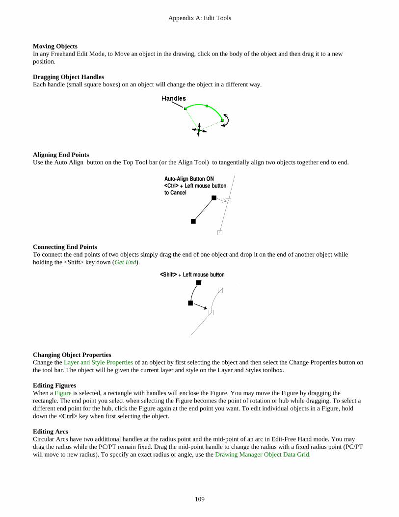
Appendix A: Edit Tools
109
Moving Objects In any Freehand Edit Mode, to Move an object in the drawing, click on the body of the object and then drag it to a new position. Dragging Object Handles Each handle (small square boxes) on an object will change the object in a different way.
Aligning End Points Use the Auto Align button on the Top Tool bar (or the Align Tool) to tangentially align two objects together end to end.
Auto-Align Button ON<Ctrl> + Left mouse buttonto Cancel
Connecting End Points To connect the end points of two objects simply drag the end of one object and drop it on the end of another object while holding the <Shift> key down (Get End).
<Shift> + Left mouse button
Changing Object Properties Change the Layer and Style Properties of an object by first selecting the object and then select the Change Properties button on the tool bar. The object will be given the current layer and style on the Layer and Styles toolbox. Editing Figures When a Figure is selected, a rectangle with handles will enclose the Figure. You may move the Figure by dragging the rectangle. The end point you select when selecting the Figure becomes the point of rotation or hub while dragging. To select a different end point for the hub, click the Figure again at the end point you want. To edit individual objects in a Figure, hold down the <Ctrl> key when first selecting the object. Editing Arcs Circular Arcs have two additional handles at the radius point and the mid-point of an arc in Edit-Free Hand mode. You may drag the radius while the PC/PT remain fixed. Drag the mid-point handle to change the radius with a fixed radius point (PC/PT will move to new radius). To specify an exact radius or angle, use the Drawing Manager Object Data Grid.

Appendix A: Edit Tools
110
Editing a Single Object If you selected a single object in the first steps (above), you can enter the drawing coordinates for the end points or enter various exact dimensions. Type the exact values for the object property into the dialog text boxes as you would any Windows Text Box (see your Windows Documentation for information on using text boxes). As you type values into the dialog text boxes, the remaining items will update to match the values you type. For example, if you enter the length of a Line, the X2 and Y2 coordinate values will change to match the length you entered while holding the angle of the Line constant. You can use the Object Data Grid to change the Layer or Style of an object by clicking the item and selecting from the list that pops up. Select any geometric property to change its value. When one value is changed, the others are updated as required. If you select a Figure, you can use the special tools for groups of objects. See the detailed description of using the Object Data Grid and Drawing Treeviewin other parts of the manual. Applying the Dual Use Edit Tools in Freehand Mode To Edit in Freehand mode, first select the Edit - Freehand button on the Drawing Tool and then select an object in the drawing. Next, click one of the dual use Edit buttons to perform the tool function such as deleting the selected object. Only the following tools operate in this Freehand Edit mode. The dual use Edit Freehand tools are all located in the top button rows of the Drawing Tool bar. To begin working in Edit Freehand Mode:
1. Select the Edit Freehand Tool|tag=Selecting the Edit Freehand Tool button on the Drawing Tool (if not already selected).
2. Click on an existing object in the drawing area. Cadrail will highlight the object it finds. 3. Next click the appropriate tool button for the function you want. The tools perform the same function as described in detail
under the CAD Edit mode section that follows. You can use the following tools in Freehand Edit mode:
DELETE
COPY
CHANGE PROPERTIES
ROTATE
SIZE
FLIP Up/down or left/right
REVERSE ARC
DIVIDE AT SPACING
DIVIDE INTO SEGMENTS
ELEVATE OBJECT
POP UP ELEVATION
CREATE FIGURE
REMOVE OBJECTS FROM
DELETE FIGURE DEFINITION
Freehand Editing Tools
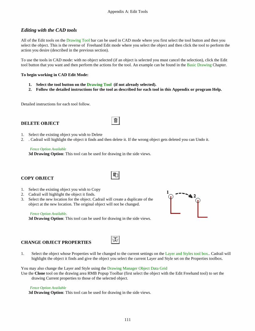
Appendix A: Edit Tools
111
Editing with the CAD tools All of the Edit tools on the Drawing Tool bar can be used in CAD mode where you first select the tool button and then you select the object. This is the reverse of Freehand Edit mode where you select the object and then click the tool to perform the action you desire (described in the previous section). To use the tools in CAD mode: with no object selected (if an object is selected you must cancel the selection), click the Edit tool button that you want and then perform the actions for the tool. An example can be found in the Basic Drawing Chapter. To begin working in CAD Edit Mode:
1. Select the tool button on the Drawing Tool (if not already selected). 2. Follow the detailed instructions for the tool as described for each tool in this Appendix or program Help.
Detailed instructions for each tool follow.
DELETE OBJECT 1. Select the existing object you wish to Delete 2. . Cadrail will highlight the object it finds and then delete it. If the wrong object gets deleted you can Undo it.
Fence Option Available 3d Drawing Option: This tool can be used for drawing in the side views.
COPY OBJECT 1. Select the existing object you wish to Copy 2. Cadrail will highlight the object it finds. 3. Select the new location for the object. Cadrail will create a duplicate of the
object at the new location. The original object will not be changed.
Fence Option Available. 3d Drawing Option: This tool can be used for drawing in the side views.
CHANGE OBJECT PROPERTIES 1. Select the object whose Properties will be changed to the current settings on the Layer and Styles tool box.. Cadrail will
highlight the object it finds and give the object you select the current Layer and Style set on the Properties toolbox.
You may also change the Layer and Style using the Drawing Manager Object Data Grid Use the Clone tool on the drawing area RMB Popup Toolbar (first select the object with the Edit Freehand tool) to set the
drawing Current properties to those of the selected object.
Fence Option Available 3d Drawing Option: This tool can be used for drawing in the side views.

Appendix A: Edit Tools
112
ROTATE OBJECT 1. Select the object to Rotate. The end point you select will become the point
of Rotation. 2. When the Input Toolbar appears, enter the rotation angle. For example,
suppose you start with a vertical line and enter an angle of 50 degrees, the line will be rotated 50 degrees in a clockwise direction. You are left with a line of the same length, but with an azimuth of 50 degrees. Suppose you start with a line that is 50 degrees, and then enter an angle of 20 degrees, you are left with a line that has azimuth 70 degrees. If a negative angle of rotation is entered, the figure is rotated counterclockwise.
3. Rotation occurs around the end point you clicked on when choosing the Figure. If you want to use the mouse for rotation (instead of inputting a number), use the Freehand Edit tools.
3d Drawing Option: This tool can be used for drawing in the side views.
SIZE OBJECT 1. Select an existing object. Cadrail will highlight the object it has found. 2. When the Input Toolbar box appears, enter the size ratio for the Object. Cadrail will enlarge or reduce the object by the
ratio you entered. 3d Drawing Option: This tool can be used for drawing in the side views.
FLIP LEFT/RIGHT UP/DOWN 1. Select a Line, Circle, Spiral, or Figure. 2. The selected object will be flipped around the axis selected. All points in a figure are flipped in relation to the end point
you selected when selecting that Figure. 3d Drawing Option: This tool can be used for drawing in the side views.
REVERSE ARC 1. Select an existing circular arc. 2. Cadrail will reverse the arc segment while the PC and PT remain fixed.
3d Drawing Option: This tool can be used for drawing in the side views.
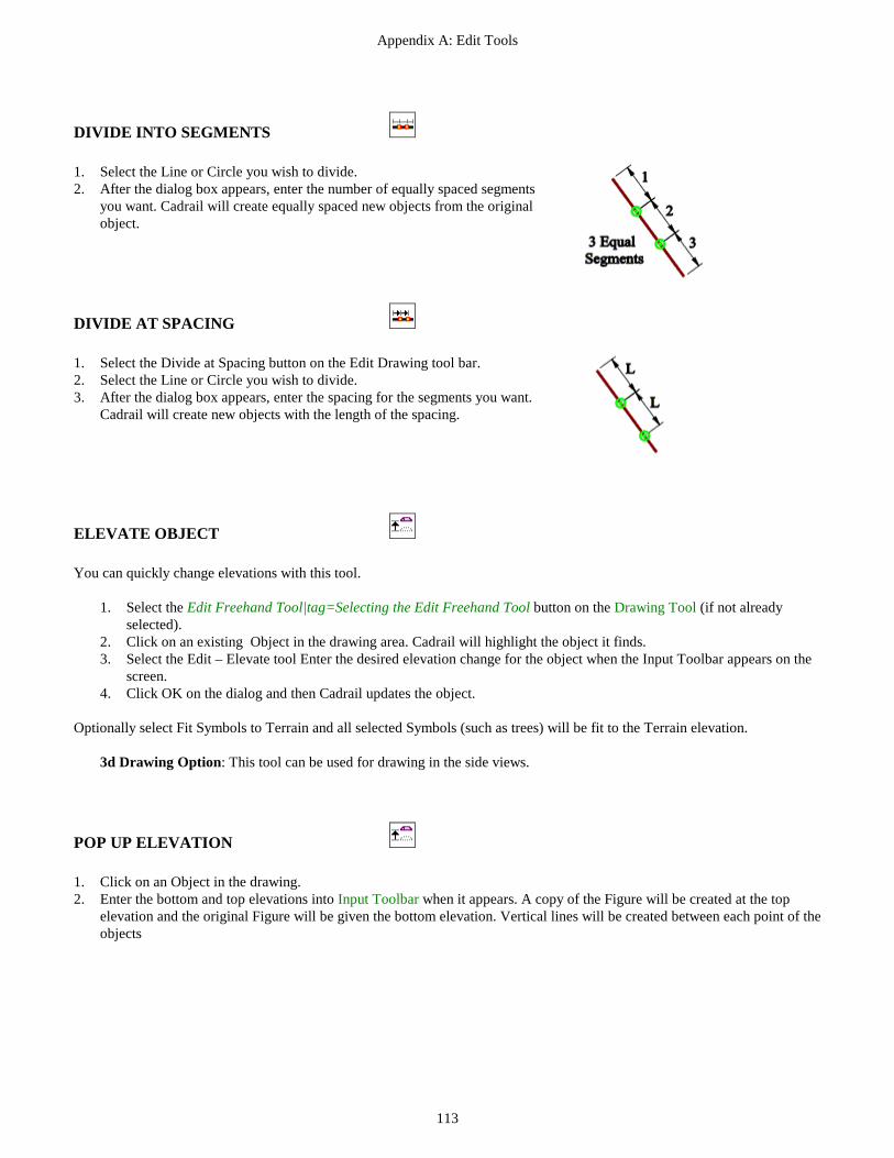
Appendix A: Edit Tools
113
DIVIDE INTO SEGMENTS 1. Select the Line or Circle you wish to divide. 2. After the dialog box appears, enter the number of equally spaced segments
you want. Cadrail will create equally spaced new objects from the original object.
DIVIDE AT SPACING 1. Select the Divide at Spacing button on the Edit Drawing tool bar. 2. Select the Line or Circle you wish to divide. 3. After the dialog box appears, enter the spacing for the segments you want.
Cadrail will create new objects with the length of the spacing.
ELEVATE OBJECT You can quickly change elevations with this tool.
1. Select the Edit Freehand Tool|tag=Selecting the Edit Freehand Tool button on the Drawing Tool (if not already selected).
2. Click on an existing Object in the drawing area. Cadrail will highlight the object it finds. 3. Select the Edit – Elevate tool Enter the desired elevation change for the object when the Input Toolbar appears on the
screen. 4. Click OK on the dialog and then Cadrail updates the object.
Optionally select Fit Symbols to Terrain and all selected Symbols (such as trees) will be fit to the Terrain elevation.
3d Drawing Option: This tool can be used for drawing in the side views.
POP UP ELEVATION 1. Click on an Object in the drawing. 2. Enter the bottom and top elevations into Input Toolbar when it appears. A copy of the Figure will be created at the top
elevation and the original Figure will be given the bottom elevation. Vertical lines will be created between each point of the objects

Appendix A: Edit Tools
114
CREATE or ADD TO FIGURE 1. Select an existing object for the first object in the Figure. 2. Select additional objects to add to the Figure. To stop, press the right mouse button or select another tool. If you select an existing figure for the first object, Cadrail will ask if you want to add objects to the existing figure or start a new figure that includes the existing figure. .
Fence Option Available 3d Drawing Option: This tool can be used for drawing in the side views.
REMOVE OBJECTS FROM FIGURE 1. Select an object in an existing Figure. Cadrail will highlight the Figure it has found. 2. Select the object you wish to Remove From the Figure. 3. Select additional objects to Remove. To stop removing from the Figure, press the right mouse button or select another tool.
3d Drawing Option: This tool can be used for drawing in the side views.
DELETE FIGURE DEFINITION 1. Select an object in an existing Figure. Cadrail will remove the Figure definition (the objects remain unchanged) .
Also available on Edit Tool bar. 3d Drawing Option: This tool can be used for drawing in the side views.
ALIGN OBJECT 1. Select the end point of an object. Cadrail automatically GETs the nearest
end point on the object you selected. 2. Select a Line, Circle, or Spiral end point. Cadrail will rotate the object you
selected in the first step so it is tangent to the second object. Furthermore, Cadrail will move the first object end point to the second end point.
3. Move the mouse around the alignment end point to get the object orientation you want and then click the mouse to fix location..
See Also: Auto-Align

Appendix A: Edit Tools
115
OFFSET OBJECT 1. Select a Line, Circle, Spiral, or Figure to offset. 2. Enter the offset distance when the Input Toolbar appears. 3. Click on the side of the existing object to locate the new offset object.
Optionally hold down the <Ctrl> key to specify the number of copies of the object to be offset.
4. Select the next object to offset or press the right mouse button to enter a new offset distance.
DIVIDE AT POINT 1. Click at the point where you want to divide a Line or Circle. Cadrail will divide the object into two separate objects using
the closest point to where you clicked.
DIVIDE AT INTERSECTION 1. Select the Line or Circle you wish to divide. 2. Select a second object that intersects the first. Cadrail will Divide the first
object selected at the intersection point with the second object that is nearest to where you clicked when selecting the second object. You may intersect two Lines, two Circles or a Line and Circle.
Note: If the point of intersection does not lie between the divide object end points, the divide object will be extended to the intersection with the second object.
TRIM AT END POINT 1. After Selecting the Trim Object tool on the Edit Drawing tool bar, select the
Line or Circle you wish to trim. 2. Select the Line, Circle or Spiral end point location for the trim. The second
trim object should be tangent to the object being trimmed. Cadrail will remove the portion of the object being trimmed that lies adjacent to the second trim object.
See Also: Auto-Trim

Appendix A: Edit Tools
116
EXTEND OBJECT 1. Select a Line end point. 2. Select the new location for the end point first selected. The opposite end
point will remain fixed while the selected endpoint is updated to the new location.
Dimension option: Length. Extend to Object Option Available
DATA BETWEEN POINTS (Info) 1. Click a free point or an Object (<Shift>+to Get Object endpoint, <Ctrl+ > to not select object where needed). 2. Click a second object or free point. 3. Information for the imaginary line between the two points is shown in the Drawing Manager Data Window. If you select an
object then a perpendicular line from the object is shown. Selecting a second object gives the distance between objects.
AUTO CREATE 1. Select an existing object for the first object in the Figure . 2. Cadrail will begin searching for objects that connect to the first object selected. When it finds a connecting object, Cadrail
will display a message asking if you want to add the object to the Figure. Select yes to add the object, select no to keep searching without adding the found object or select cancel to stop searching. Object end points must be within 0.1 units for a connection to be found. Figures
The direction Cadrail takes for the automatic search is indicated by the end point you select for the first object in the figure. Therefore, the second object Cadrail finds will be connected to the end point you first select.
INSERT TURNOUT 1. Select an existing Turnout to be Inserted. 2. Select the Insertion point on an existing Line in the drawing. 3. Move the mouse pointer around the Insertion point until you see the
orientation you want and then click the mouse.
Auto-Trim Available.

Appendix A: Edit Tools
117
SLIDE TURNOUT 1. Select a Turnout that you want to Slide. 2. Move the mouse pointer along the line projected from the Turnout leg selected
in step 1. 3. Select the new location for the Turnout.
Auto-Trim Available
CONNECT TURNOUT 1. Select a base Turnout in the drawing. 2. Select a Line or Circle in the drawing. Cadrail will create an new tangent
object from the end of the Turnout selected in step 1 to the object selected in step 2.The Arc will point in the direction of the End Point selected in step 2.
Auto-Trim Available
TURNOUT LADDER 1. Select a base Turnout leg in the drawing. The leg selected must be one of
the two forward legs of the Turnout. The direction the new Turnout faces will be determined by the selected base Turnout leg as shown in the sketch.
2. Select a yard Line in the drawing. The yard Line must be parallel to the opposite side of the Turnout leg selected in step 1.
Auto-Trim Available Option: Hold the Shift key down in Step 2 to specify a different Turnout type from
that selected in step 1.
CROSSOVER TURNOUTS 1. Select a base Turnout in the drawing. 2. Select a yard Line in the drawing. The yard Line must be parallel to the
opposite side of the Turnout leg selected in step 1 Auto-Trim Available

118
Line Tools Line drawing are used to create Lines in many different ways. The Line tool buttons are located in the center area of the Drawing Tool bar.
FREE HAND LINE 1. Select the beginning end point for the new line. 2. Select the second end point of the line.
Dimension option: Length and/or Azimuth. 3d Drawing Option: This tool can be used for drawing in the side views.
MULTIPLE 1. Select the beginning end point for the new line. . 2. Select the second end point of the line. 3. Continue selecting the second end point for additional lines. The second end
point becomes the first end point for the next Line. To start a new string of lines, press the right mouse button.
Dimension option: Length and/or Azimuth. Option: Hold <Ctrl> key down in step 1 to enter Elevation. Option: Hold <Alt> key down in step 1 to Create a Figure. 3d Drawing Option: This tool can be used for drawing in the side views.
RECTANGLE 1. Select the beginning corner for the new rectangle. 2. Select the opposite corner. Four individual lines are made to represent the
rectangle.
Dimension option: Length and/or Azimuth. Option: Hold <Ctrl> key down in step 1 to enter Height and Width. Option: Hold <Alt> key down in step 1 to Create a Figure.
3d Drawing Option: This tool can be used for drawing in the side views.

Appendix A: Line Tools
119
VERTICAL (z axis) 1. Select the location of the new line on the Plan View. 2. After the Input Toolbar appears, enter the Elevations for the Vertical line end points. If you use GET END for the first end
point location, that elevation will be used for the first end point.
Dimension option: Length
PERPENDICULAR 1. Select a point on an existing line. This will become the first end point of the
perpendicular line. 2. Select the second end point of the new line.
Dimension option: Length. Extend to Object Option Available
BETWEEN CIRCLES 1. Select the approximate line end point on an existing circle (PC). 2. Select the second approximate end point on a second existing circle (PT).
Cadrail will construct a tangent line between the two circles using the closest match to the two points you picked on the circles. Dimension option: Length. Auto-Trim Option Available.
CIRCLE TO POINT 1. Select the approximate line end point on an existing circle (PC) . 2. Select the second end point of the tangent line. Cadrail will construct a tangent
line to the circle using the second point.
Dimension option: Length. Auto-Trim Option Available.

Appendix A: Line Tools
120
TANGENT LINE 1. Select a Tangent point (or End Point) on an existing Arc or Spiral. 2. Move the mouse to the second End Point. Cadrail will force the new Line to
be Tangent to the existing object and trim the existing object at the tangent point.
Dimension option: Length. Auto-Trim Option Available. Extend to Object Available
DIMENSION LINES 1. Select the end point of an object in the drawing. 2. Select a second end point in the drawing. 3. Move the mouse to display the Dimension you desire and then click the mouse
to fix the Dimension. Note: you can change the Dimension properties with the Drawing Manager Object Data Grid. The default Dimension size is set in the Drawing Preferences dialog box.

121
Circle Tools Arcs and circles are easy to draw with Cadrail’s many tools located near the bottom of the Drawing Tool bar.
PC TO RADIUS 1. Select the PC point for the new circular arc. 2. Select the Radius point of the arc. 3. Select the PT point of the arc. The direction you move after setting the radius
point will determine the direction of the arc. Dimension option: Radius and/or Angle.
RADIUS TO PC 1. Select the Radius point of the new arc. 2. Select PC point of the arc. 3. Select the PT point of the arc. The direction you move after setting the radius
point will determine the direction of the arc
Dimension option: Radius and/or Angle.
FULL CIRCLE 1. Select the Radius point for the new circle. 2. Select a point on the circumference of the new Circle.
Dimension option: Radius.

Appendix A: Circle Tools
122
ARC FILLET (BETWEEN TANGENTS) 1. Select a Line or Arc for the first tangent. . 2. Select the second Line or Arc for the second tangent. 3. Move the mouse pointer around the selected objects. As you move Cadrail
shows the possible positions for the new Arc. Furthermore, Cadrail will vary the Arc radius as you move. Click to select the radius point of the new Arc. Press the Alt+key while moving to Reverse the arc (ice cream cone shaped).
Dimension option: Radius. Auto Trim AvailableExtend to Object Available
ARC FROM 3 POINTS 1. Select the first end point (PC) for the arc (or end point on an existing Line,
Arc, or Spiral). 2. Select the second end point (PT). 3. Move the mouse to the third point on the Arc. Cadrail creates an arc through
the 3 points as you move the mouse. Click to set the 3rd point and the arc.
Dimension option: Radius.
TANGENT ARC 1. Select the Tangent point (or end point) on an existing Line, Arc, or Spiral. 2. Move to the radius point of the Arc. 3. Move the mouse to the second End Point for the new Arc. Cadrail will force
the new Arc to be Tangent to the existing object. The existing object will be trimmed at the tangent point.
Dimension option: Length. Auto Trim Available Extend to Object Available
PROJECT ARC 1. Select an Arc end point. This will be the first end point for the new Arc. 2. Select the second end point of the new Arc by moving the mouse. The new
Arc will extend from the existing Arc.
Dimension option: Length. Extend to Object Available

123
Spiral Tools Spirals are a special shape that is like a line on one end and an arc on the other. These tool buttons are near the bottom of the Drawing Tool bar.
FREE HAND SPIRAL 1. Select the TS end point. 2. Select a second point on the Spiral tangent line in the direction of the Spiral
SC. 3. Select the SC of the Spiral by moving the second or free end to the location
you like.
Dimension option: Length and/or Radius.
PARALLEL TO TANGENT 1. Select the end point of an existing Circle or Spiral. This will be the SC of the
Spiral. 2. Select an existing Line that will be parallel to the TS tangent. Cadrail will
construct a spiral with a radius equal to that of the Circle at the SC. Because the radius is fixed, the TS may not lay on the existing line. Cadrail will pick the Spiral orientation that puts the TS closest to where you click on the tangent line.
FIT TO TANGENT 1. Select the end point of an existing Circle. This will be the SC of the Spiral. 2. Select an existing tangent Line that will contain the Spiral TS. Cadrail will
construct a spiral that matches the tangent Line at the TS. The Spiral radius at the SC will be adjusted depending on the tangent. Therefore, it is possible for the Spiral radius to be less than the Circle. Cadrail will pick the Spiral orientation with the TS point nearest to where you click on the tangent line in Step 2.

Appendix A: Spiral Tools
124
BETWEEN TANGENT LINES
1. Select the first tangent line. Click on the end of the tangent to indicate what quadrant to put the arc.
2. Select the second tangent line end point. 3. Move the mouse pointer around the tangent lines. You can choose to
place the Spirals in any of four possible quadrants made by the tangents. Cadrail will vary the radius as you move. Click to select the SC point of the new Spirals.
Dimension option: Radius. Auto-Trim Available
BETWEEN TANGENTS WITH ARC 1. Select the first tangent line. Click on the end of the tangent to indicate
what quadrant to put the arc. 2. Select the second tangent line end point. 3. Select the radius for the two Spirals. Cadrail will construct two equal
Spirals between the two tangents with a central Arc. As you move, the radius of the Spirals and Arc will vary. Press the Alt+key while moving to Reverse the Spirals and Arc (ice cream cone shaped).
Dimension option: Radius. Auto-Trim Available
TANGENT spiral 1. Select the Tangent point (or end point) on an existing Line, Arc, or Spiral. 2. Move the mouse to the second End Point for the new Spiral. Cadrail will force
the new Spiral to be Tangent to the existing object. The existing object will be trimmed at the tangent point.
Dimension option: Length and/or Radius. Auto-Trim Available

125
Symbol Tools
PLACE TEXT 1. Select the upper left location for the Text 2. Enter the desired Text when the Text Box and Text Editor Toolbar appears in the drawing area. 3. Enter the Text Height, Font, Bold, or Italic. The Text Height is in drawing units and will scale in relation to the drawing. .
Text Editing Toolbar in the Drawing Plan View.
TEXT STRINGClick here Text Height inDrawing Units
Rotation
To change existing text in your drawing Double Click the text
.
POINT SYMBOL 1. Select the Point Symbol from the Symbols pop up menu. 2. Select the Point location or click the Symbol location on an object. 3. If a flag or tree symbol was selected from the pop up menu, move the mouse pointer to rotate and size the Symbol.
Dimension option: Radius, Elevation. 3d Drawing Option: This tool can be used for drawing in the side views.
DISTANCE AZIMUTH 1. Select the first reference point location. 2. When Input Toolbar appears, enter the distance and the azimuth to the next
point (measured from first reference point). 3. Continue creating new points from the first reference point or cancel to start
over.
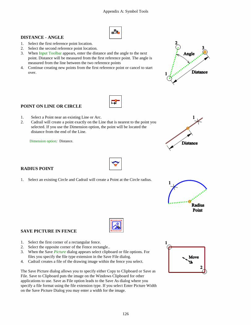
Appendix A: Symbol Tools
126
DISTANCE - ANGLE 1. Select the first reference point location. 2. Select the second reference point location. 3. When Input Toolbar appears, enter the distance and the angle to the next
point. Distance will be measured from the first reference point. The angle is measured from the line between the two reference points
4. Continue creating new points from the first reference point or cancel to start over.
POINT ON LINE OR CIRCLE 1. Select a Point near an existing Line or Arc. 2. Cadrail will create a point exactly on the Line that is nearest to the point you
selected. If you use the Dimension option, the point will be located the distance from the end of the Line.
Dimension option: Distance.
RADIUS POINT 1. Select an existing Circle and Cadrail will create a Point at the Circle radius.
SAVE PICTURE IN FENCE 1. Select the first corner of a rectangular fence. 2. Select the opposite corner of the Fence rectangle.. 3. When the Save Picture dialog appears select clipboard or file options. For
files you specify the file type extension in the Save File dialog. 4. Cadrail creates a file of the drawing image within the fence you select. The Save Picture dialog allows you to specify either Copy to Clipboard or Save as File. Save to Clipboard puts the image on the Windows Clipboard for other applications to use. Save as File option leads to the Save As dialog where you specify a file format using the file extension type. If you select Enter Picture Width on the Save Picture Dialog you may enter a width for the image.

127
Special Drawing Tools The following tools may be combined with other applicable drawing commands.
AUTO-ALIGN OPTION Auto-Align is used in combination with the Freehand Edit. The ON/OFF button for Auto-Align is located on the Top Tool bar. Use this tool to connect objects together end-to-end tangentially. The tool button can be ON (pressed down and highlighted) or OFF. When the button is on, whenever you drop one object on the end of another the objects will be aligned. You can cancel or activate Auto-Align temporarily by holding down the <Ctrl> key when selecting the Object to be aligned. If Auto-Align is ON alignment is canceled by holding down the <Ctrl> key. If Auto-Align is OFF, holding the <Ctrl> key will activate alignment (see Edit Freehand Tools-). To use Auto-Align:
1. Click the Edit Freehand button on the Drawing Tool bar (if not already selected). 2. Click on a Line, Arc, or Spiral object in the drawing area. Cadrail will highlight the object it finds. 3. Click the Auto-Align button so it is ON (pressed down and highlighted). If the buttons are already ON you can skip steps 1, 2 and 3.
Cross the bodies of the Objects near the ends
4. Drag an object to a second object in the drawing and then drop the end of the first object onto the end of a
second object so that the bodies of the objects cross. If the end points of the two objects are close together when you drop, the Alignment tool is activated. If the Align button is off, you can still activate alignment by holding down the <Ctrl> key when you drop the object (or if the Align button is on, you can cancel Alignment by holding down the <Ctrl> key).
5. Move the Mouse Pointer around the alignment point. As you move around the four possible 90 degree quadrants, the object will change its alignment position on the screen. The object follows the Mouse Pointer around the quadrants.
6. Click when the object on the screen is pointed in the direction that you want.
There is a detailed example of using the Auto-Align feature in the Tutorial Example Drawing 2. The CAD Edit -Align tool can also be used to align objects.. See its description in the Edit tools section of the manual.

Appendix A: Special Tools
128
AUTO-FIND OPTION This is a powerful option button located on the Labels toolbar that highlights the object the mouse pointer is over. Then if you click the mouse at that position the object highlighted is selected. If no object is selected in the drawing, the object data for the Auto-Find highlight object is shown in the Drawing Manager as you move the mouse. Other keyboard options can be used with Auto-Find. For example, GetEnd <Shift> will draw a small circle around the nearest end point. Using Cancel Figure Selection <Shift>+<Ctrl > highlights individual objects in a Figure instead of the entire Figure as you move the mouse.
AUTO-SELECT OPTION When Auto-Select is ON, on the Labels Tool bar, Cadrail will select and highlight the object that was just created by a drawing tool. You can then edit the object in Freehand Edit Mode or repeat the drawing tool.
AUTO-TRIM OPTION When Auto-Trim is ON on the Drawing Tool bar (Freehand Edit mode), Cadrail will trim the ends of any connecting Objects that overlap a tangent Object.
To use Auto-Trim: 1. Click the Auto-Trim button on the Drawing Tool bar (active when any tool group
besides Freehand Edit is selected). 2. Tools that cause tangent Objects to overlap (such as the CAD-Circle Between Tangents
tool) will trim off the overlap. You can cancel or activate Auto-Trimming temporarily by holding down the <Ctrl> key when performing the last tool step. When Auto-Trim is ON (item is checked on the Edit menu) trimming will be canceled by holding down the <Ctrl> key. If Auto-Trim is OFF, holding the <Ctrl> key will activate trimming for a single tool.
CANCEL FIGURE SELECTION Select a single object in an existing Figure by holding down the <Ctrl> +<Shift> key when clicking the object (with tools that do not have the Get End option you only need to press the Ctrl key).
CLONE PROPERTIES Change the current drawing default Layer and Style by selecting an Object with the Freehand Edit tool and then click the Right Mouse Button in the drawing area to show the RMB Popup Toolbar .. Select Clone on the menu to change the current drawing properties to those of the selected object.
GET END Sometimes you will want to tell Cadrail to Get the End of an object. Press the <Shift> key and the Left mouse button when selecting an object end point. Cadrail will substitute the exact object end point coordinates in the command. Cadrail will find the end point nearest to where you clicked on the object. The end point will be highlighted with a small circle.

Appendix A: Special Tools
129
GET OBJECT With some tools you may want to tell Cadrail to use an object instead of clicking a point in the drawing (also EXTEND TO OBJECT). Press the <Shift> key and the Left mouse button when selecting an object and Cadrail will use the object with the tool. For example, to extend an object to another object, use the extend tool but click an object while holding the <Shift> key for the second end point of the object.
LAST TOOL The Last Tool button on the RMB Popup Toolbar .shows the previous tool that was used. Select the button to return to the Last Tool just as if it was selected from the Drawing Tool Bar.
POSITION FRONT/BACK You can make one object appear on top of another on the drawing screen using the Edit – Position item on the Main Menu bar or the RMB Popup Toolbar ..
1. Select the object with the Edit Freehand Tool, and then select the Position Front or Back item from the menu.
RMB POPUP TOOLBAR PLAN VIEW There are additional tools and features found on the (Right Mouse Buttong) RMB Popup Toolbar . Click the RMB in the Plan View drawing area to show the toolbar.
SELECT IN FENCE Use a Fence to select a group of objects. The objects that are completely enclosed within the fence will be selected. If an object is within the fence and part of a Figure, the entire Figure will be selected. 1. Hold down the Ctrl key and press the Left mouse button at the first corner of a rectangular fence (it is not necessary to
hold Ctrl key with Freehand Edit). 2. Select the opposite corner of the Fence rectangle. Cadrail will select the objects that are totally enclosed within the fence.
UNDO/REDO To Undo the last drawing change, select Edit-Undo on the Main Menu. Cadrail will reverse the last drawing Action. A second method to Undo is to click for the RMB Popup Toolbar and then Click the Undo button on the toolbar. REDO the last Undo by selecting Edit-Redo on bar or on the RMB Popup Toolbar. Cadrail will reverse the last Undo drawing Action.

130
Appendix B: What’s On the DVD? An optional DVD is available with the Cadrail program and additional drawings.
About the Track Libraries While you design your layout, you may incorporate Figures from the Cadrail libraries. You can also develop your own libraries exactly the way you like them. The library Figures are simply Cadrail drawings that you can open and modify as you do any drawing. When you install Cadrail, some of the more common library files will be copied on to your hard drive and placed in the Cadrail folder. The remaining files are located on the Cadrail disc in the folder named DRAWINGS. There are Figures of generic railroad shapes that can be re-sized for any scale (the size of the generic Figures in the Libraries is HO unless stated otherwise) and Figures of manufactured products that represent a specific track section and should only be used for the specific scale they represent (if you re-size to another scale, you may lose some accuracy). Individual Figures are named by the Model Scale, Manufacturer’s brand name and part number. You can convert from one model scale to another by using a size ratio. For example, you may know that HO is approximately (see table for exact values) "half O". In other words everything on an O scale layout is around double the size as HO. Therefore, to convert an HO figure to O, select the Figure-Size command from the Drawing tool bar, use an X and Y factor of 1.81 (see table in the chapter Railroad Design Issues for exact ratios) and you have an O scale figure. The only dimension of real concern between scales is the curve radii. A 45 degree angle is a 45 degree angle in any scale. Track Name Conventions:
HO_A_100.CRW
A281 #4
Model Scale Manufacturer
Manufacturer
Manufacturer’s Part Number
Description
Example Figure Name :
Example Library File Name:
Track Code
Manufacturer Abbreviations:
• A - Atlas • E - Micro Engineering • G - LGB • L - Lionel • M - Marklin • R - Roco • S - Shinohara • W - Walthers

i
Index 3D Runrail, 86 3d shapes, 76 3d Terrain Grid, 43 3d View
Example Tutor, 40 3D View, 59 3d View Print, 61 3d View Save Picture, 61 About Manual, 2 Add To Figure, 114 align
cancel/activate, 127 Align, 24, 109, 114
Freehand Edit, 127 All Objects, 46 Angle
Units, 81 angles, 74, 90 Angles, 73 Arc, 18, 24 Arc from 3 points, 122 Arc Tools, 121 Arcs, 109 AUTO CREATE FIGURE, 116 Auto-Align, 127 Auto-Emankment, 43 Auto-Find, 128 Automatic Updates, 72 Auto-Save, 72 Auto-Select, 128 Auto-Terrain 3D View, 62 Auto-Trim, 128 Azimuth, 18 backup, 72 Base Elevation, 62 BETWEEN 2 CIRCLES
line, 119 BETWEEN 2 Tangents Spiral, 124 Bird’s Eye View, 86 bitmap, 20, 77, 79 BMP format, 79 bold, 72, 125 border, 58 Bottom Tool, 4 building the layout, 93 Cab View, 86 CAD Edit Mode, 111 Cadrail Preferences, 71 cancel, 128 Cars, 86 Change, 36
Coordinates, 75 change coordinates, 110 change file name, 12 change Layer, 110 Change Object, 67
Change Properties, 111 Change Properties, Figures
Toolbox, 69 change Style, 110 circle, 18 Circle, 24 CIRCLE TO POINT, 119 Circle Tools, 121 clearance, 88 clicking, 7 Clipboard, 79 Clone, 75 Clone Properties, 63, 111, 128 close drawing, 10 color, 71 Color Fill, 53 compound curve, 90 connect, 24
Align, 114 Connect Turnout, 117 convert, 79 Convert previous version, 103 coordinate, 10 Coordinate Input , 29 coordinate system, 44 coordinates, 75 Copy, 28, 111 create, 13 Create Figure, 35 CREATE FIGURE, 114 CREATE POLYLINE, 118 Create Text, 125 Creating, 13 Crossover, 98 Crossover Turnouts, 117 cube, 76 current properties, 63 cursor shapes, 8 curve, 90 cylinder, 76 Data Between Points, 116 default
preferences, 71 default settings, 72 Degrees Minutes, 73 Delete, 111 Delete Definition (Figure), 114 Delete Style, 66 delta, 19 Delta X, Y, 75 design guidlines, 87 dimension, 100 Dimension, 29 Dimension format, 72 Dimension Line, 120 Dimension Option
Mouse Pointer Shapes, 8 Dimension Options, 74 Dimension Size, 70 Direction, 84 Display, 48 Display Labels, 48 Distance
Units, 81 Distance - Angle, 126 Distance - Azimuth, 125 Divide, 36
Commands, 115 double, 91 Double line, 66 double-clicking, 7 download problems, 102 Drag Screen, 46 dragging, 7 drawing, 87 Drawing Figures Treeview, 68 Drawing Manager, 67 Drawing Preferences, 70 drawing setup, 70 Drawing Tabs, 10 Drawing Template, 70 Drawing Tool Bar, 11 Drawing Tutorial, 21 DXF, 79 easement, 19, 90, 92, 100 Edit, 15, 22, 107
tools, 107 Edit Figures, 68 Edit Freehand
Mouse Pointer Shapes, 8 Edit Freehand Mode, 107 Edit Freehand Tools, 15 Edit Freehand Tools, 22 Edit Object, 75, 110
Drawing Manager, 67 Edit Objects, 67 Edit Picture, 77 Edit Tool Group, 107 Editing, 13 electronic mail, 3 Elevate Object Tool, 113 Elevate Tree Symbols, 113 elevation, 62, 113
discussion, 93 example, 35 labels, 48
Elevation, 56 showing, 48
elevations, 37 Emankment, 43 end, 12
getting, snaping, 128

Appendix A: Special Tools
ii
end a command, 14 End Cap, 66 End Caps, 68 end points
labels, 48 Entering Numbers, 73 equipment, 1 Esc, 6 Exit, 12 Export, 79 Export PDF, 79 exporting, 79 extend
to object, 129 Extend
Mouse Pointer Shapes, 8 EXTEND, 116 extension, 12 Extents, 46 features, 5 feet, 73 Feet Inches Input, 73 fence, 129 Fence, 129 Figure, 20, 50, 100
cancel selection, 128 FIGURE
CREATE, 114 Figure Name, 53 Figure Tools, 116 Figure-Properties, 51 Figures, 27, 101 Figures Library, 69 Figures Tool Box, 50 Figures, Ordering, 68 file
Open, 9 file format, 79 File Open Dialog, 9 Fill Child Figures, 53 Fill Color, 53 fill Figure, 53 Fill Opacity, 53 filled Figure, 54 Fillet ARC, 122 Find All Turnouts, 85 Find, Auto, 128 fit to Tangent, 123 Fixed Line Style, 65 Flat Line Style, 65 Flip, 112 font
drawing, 70 screen, 72 Text, 125
format, 79 free hand Line, 118
FREE HAND Point, 125 Free HAND Spiral, 123 Freehand Edit Mode, 107, 110 Freehand Edit Tools, 15 Freeze, 17, 48 frog, 94 Front/Back, 129 Full CIRCLE, 121 get end, 128 Get End, 23, 128 Get Object, 129 GIF format, 79 grade, 37
Freehand Edit, 78 labels, 48
Grade defined, 56 showing, 48
grid , 26, 47 grid line printing, 104 group, 20, 50, 129 handle, 109 heading, 58 helix, 91 Help
Tech Support, 3 hot keys, 6 Hot Keys, 6, 61 image, 20, 77 import, 79 Import, 79 importing, 79 inch, 73 increment
Grid, 47 Snap, 47
Input Object Number, 74 Input Toolbar, 73 insert
Figure, 69 Insert Picture, 77 Insert Turnout, 116 install, 1 Installation problems, 102 Instruction Line, 5 intersect, 115 italic, 72, 125 join, 24 JPG format, 79 key board shortcuts, 6 keyboard, 6 keys
shortcut, 6, 61 label
screen, 48 Ladder, 117
drawing yards, 96
Landscape, 58 Last Tool, 75 Last View, 46 layer, 17, 64, 100 Layer, 111
delete, 64 new, 64
Layer and Styles, 36, 63 Layer Contol 3D View, 62 Layer Properties Tab, 68 Layer Structure, 64 Layers
Importing, 80 Layout Tab, 57 Length, 18, 29 length of curve, 19 Libraries , 130 Library Folder, 80 Library Tab
Drawing Manager, 69 Limits, 81 line
defined, 18 style,width, 65
Line Dimension format, 72 Line End Caps, 68 line size, 103 Line Tools, 118 load Figures, 69 Locked, 52 Main Menu, 4 Materials Report, 80 merge
drawing, 79 mesh, 62 monitor, 1 mountain, 43 Mouse Pointer Shapes, 8 Move Style, 66 moving, 7 MULTIPLE LINES , 118 name
drawing, 12 Figure, 53
new object, 14
new drawing, 12 New Drawing, 70 New Style, 66 North, 18 Numbers, Entering, 73 object da, 128 Object Data Grid, 67 object number, 17, 48 Object Number Input, 74 Object Tab
Drawing Manager, 67

Appendix A: Special Tools
iii
Object, Edit, 67 objects, 17 ODG
Popup Toolbar, 75 Offset, 36, 66 OFFSET, 115 old version, 103 Opacity, 53 open, 9 Open Figures, 69 operation, 82 operation, train, 82 Optimize Drawing, 81 Overhead View, 86 paper, 57 Paper size, 58 parallel, 66 parallel lines, 91 PARALLEL to Tangent, 123 Parent and Child Layers, 64 pattern, 53 PC, 19 PC to Radius, 121 PDF format, 79 perpendicular, 119
defined, 19 Personal Library, 80 PI, 94 Picture, 77 Picture fill (Figure), 54 Picture Format, 126 Picture Object, 20 Picture Paint, 77 Picture Size, 126 Picture, 3d View Save, 61 Place Train, 83 Plan View, 10, 44 PNG format, 79 Point on Line or Circle, 126 Point Tools, 125 Point Train, 84 pointing, 7 Polyline, 118 POP UP elevation, 113 Popup Menu, 129 Popup Toolbar, 75 Position Front/Back, 129 Preferences, 71 print, 57
3d View, 61 Print PDF, 79 Printer Setup, 58 printing problems, 104 Profile
Selecting, 75 Profile Dialog, 78 Project ARC, 122
properties, 63 Properties, 109
changing, 111 Figure, 51
Properties Tab, 68 Properties, Change, 67 PT, 19 questions
support, 3 Quick Edit Tools, 15 quit, 12 radius, 18
labels, 48 Radius Point, 126 Radius to PC, 121 railroad guidlines, 87 RECTANGLE, 118 Redo, 16, 129 Redraw, 46 Remove From Figure, 114 rename file, 12 Requirements, 1 resize
tool, 112 Reverse, 84 REVERSE ARC, 112 reverse curve, 89 RMB Popup Menu, 129 RMB Popup Toolbar, 75 rotate, 112 Rotate, 108
Mouse Pointer Shapes, 8 Runrail, 82 Runrail 3D, 86 Runrail problems, 101 save
auto, 71 Save, 72
drawing, 12 settings, 81
Save As, 12 Save Picture, 126 Save Picture 3d View, 61 SC, 19 scalable line style, 65 scale
model railroad, 87 print to, 57 tool, 112
segments, 113 selecting, 7 Send Front/Back, 129 settings, 72 setup
preferences, 71 Setup, 1 Setup problems, 102
Shape Builder, 76 shortcut, 6, 61 shortcut keys, 6 Show All Objects, 46 Side View
defined, 49 example, 39
Siding, 97 simulation, 82 size, 112
drawing, 45 Size Picture, 126 Slide Turnout, 117 slope, 56 snap, 47
to end, 128 to end point, 128
Snap, 30 Solid Line Style, 65 Spacing, 113 Speed, 86 spiral, 19, 92, 100 Spiral Tools, 123 station
defined, 55 example, 39 labels, 48
Stations, 39 Stop Train, 86 style, 65 Style, 17, 111 Style Delete, 66 Style Move, 66 Style New, 66 Style Properties Tab, 68 Styles, 63
Importing, 80 support, 3 switch, 95
drawing, 94 drawing yards, 96
Switch, 52 Builder, 76
switches, 84 Symbol, 125 Symbol Fit Terrain, 113 Symbols, 19 Tabs, 10 tangent
defined, 18 Tangent, 89 tangent ARC, 122 tangent lINE, 120 tangent SPIRAL, 124 Technical Support, 3 Template, 70 Terrain, 43, 62

Appendix A: Special Tools
iv
Terrain Fit Trees, 113 Terrain Grid, 43 text, 20 Text, 125 Text Box, 73 Text Height, 70 Text Help, 3 tips, 21 tool bar positions, 72 Top Tool, 5 Track Libraries , 130 Track Library, 80 train properties, 85 Train Speed, 86 transparency, 54 Transparent, 53 Trees Fit Terrain, 113 Treeview, Drawing, 68 Trim, 115, 128 Trouble Shooting, 81
TS, 19 turnout, 94, 130 Turnout, 95
connect, 117 crossover, 117 drawing yards, 96 insert, 116 property, 52 slide, 117
Turnout Builder, 76 Turnout Ladder, 117 turnouts
find all, 85 Turnouts, 84 TUTOR, 29 Tutorial, 21 Un-Couple, 84 Undo, 16, 129 units, 58, 70, 81 Units, Input, 73
Updates Automatic, 72 VERTICAL LINE, 119 View, 10, 26, 44 Visible, 17, 48, 63 window, 44 window settings, 81 window size, 72 wire mesh, 62 WMF file format, 79 WMF format, 79 Work Sheet, 80 yard, 97
drawing, 96 Yard, 117 Yard Builder, 77 yards, 52 Zoom In, 46 Zoom Out, 46 Zoom to Object, 46


![Efficient Simulation of Furniture Layout Taking into ...yamakawa/CASA2016/... · layout problem [2]. This method learns the re-lationship between furniture items from a set of example](https://static.fdocuments.net/doc/165x107/5f6faffc2c2d8f218827f48a/eficient-simulation-of-furniture-layout-taking-into-yamakawacasa2016.jpg)


