
CADD Standards - · PDF file- 2 - Print Production Introduction There has been a tremendous...
27
City of Lincoln November, 2005 Volume 1, Issue 1 PUBLIC WORKS & UTILITIES Working together to provide quality services to our community Print Production
-
Upload
phamnguyet -
Category
Documents
-
view
226 -
download
0
Transcript of CADD Standards - · PDF file- 2 - Print Production Introduction There has been a tremendous...

City of LincolnNovember, 2005
Volume 1, Issue 1
PUBLIC WORKS & UTILITIES Working together to provide quality services to our community
Print Production

- i -
Table of Contents PRINT PRODUCTION ..........................................2
INTRODUCTION ......................................................2 PRINT REQUIREMENTS...........................................2
WORKSPACE.........................................................3 INTRODUCTION ......................................................3
Lincolnv851.cfg................................................3 ProjNo.cfg........................................................3
PRINT DRIVERS....................................................4 INTRODUCTION ......................................................4
Table 1 .............................................................4 PEN COLOR ASSIGNMENTS..............................5
INTRODUCTION ......................................................5 Table 2 .............................................................5 Table 3 .............................................................5 Table 4 .............................................................5
LINE WEIGHT .......................................................6 INTRODUCTION ......................................................6
Table 5 .............................................................6 PENTABLES ...........................................................7
INTRODUCTION ......................................................7 Table 6 .............................................................7 BW_Pentable....................................................8 CR_Pentable ....................................................9 EC_Pentable ....................................................9 JG_Pentable.....................................................9 PM_Pentable....................................................9 RW_Pentable..................................................10 WW_Pentable.................................................10 TS_Pentable ...................................................11
BORDERS..............................................................12 INTRODUCTION ....................................................12
Figure 1..........................................................12 REFERENCE .........................................................13 ENHANCEMENTS..................................................13
Table 7 ...........................................................13 Figure 2..........................................................13 Figure 3..........................................................14 Figure 4..........................................................14
PLOTTING MACRO............................................15 INTRODUCTION ....................................................15 DESCRIPTION .......................................................15
Table 8 ...........................................................15 BATCH PLOT .......................................................16
INTRODUCTION ....................................................16 PRINTER SPECIFICATION...............................17
INTRODUCTION ....................................................17 Figure 5..........................................................18
BATCH JOB SET..................................................19 INTRODUCTION ....................................................19
Table 9 ...........................................................19 LOGICAL NAMING ............................................20
INTRODUCTION ....................................................20 STANDARD BASE FILE NAMING CONVENTION.....20
Table 10 .........................................................20 PDF COMPOSER .................................................21
INTRODUCTION ....................................................21

This page left blank intentionally

- 0 -
Print Production

- 1 -
This page left blank intentionally
- 2 -
Print Production
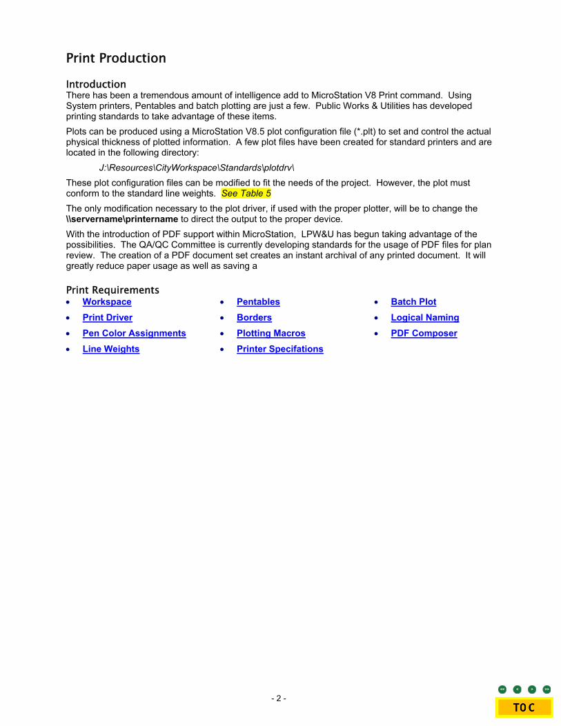
Introduction There has been a tremendous amount of intelligence add to MicroStation V8 Print command. Using System printers, Pentables and batch plotting are just a few. Public Works & Utilities has developed printing standards to take advantage of these items. Plots can be produced using a MicroStation V8.5 plot configuration file (*.plt) to set and control the actual physical thickness of plotted information. A few plot files have been created for standard printers and are located in the following directory:
J:\Resources\CityWorkspace\Standards\plotdrv\ These plot configuration files can be modified to fit the needs of the project. However, the plot must conform to the standard line weights. See Table 5 The only modification necessary to the plot driver, if used with the proper plotter, will be to change the \\servername\printername to direct the output to the proper device. With the introduction of PDF support within MicroStation, LPW&U has begun taking advantage of the possibilities. The QA/QC Committee is currently developing standards for the usage of PDF files for plan review. The creation of a PDF document set creates an instant archival of any printed document. It will greatly reduce paper usage as well as saving a
Print Requirements • Workspace • Print Driver • Pen Color Assignments • Line Weights
• Pentables • Borders • Plotting Macros • Printer Specifations
• Batch Plot • Logical Naming • PDF Composer
- 3 -
Workspace
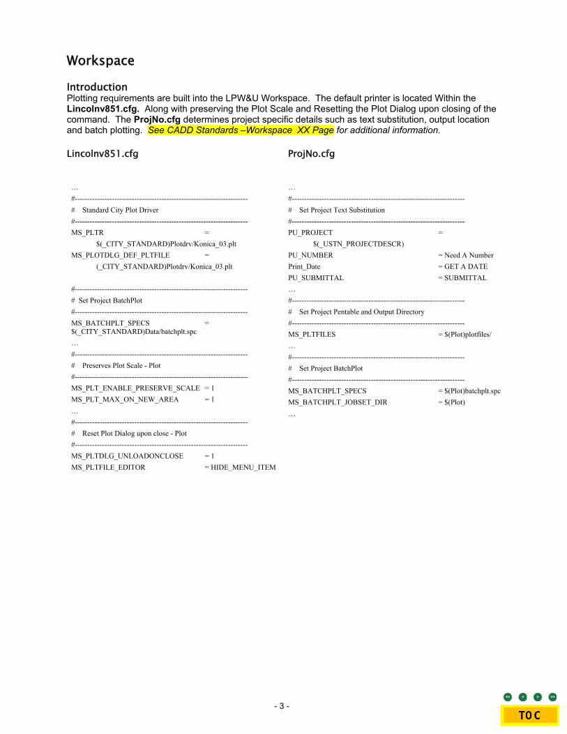
Introduction Plotting requirements are built into the LPW&U Workspace. The default printer is located Within the Lincolnv851.cfg. Along with preserving the Plot Scale and Resetting the Plot Dialog upon closing of the command. The ProjNo.cfg determines project specific details such as text substitution, output location and batch plotting. See CADD Standards –Workspace XX Page for additional information.
Lincolnv851.cfg
ProjNo.cfg
… #---------------------------------------------------------------------- # Standard City Plot Driver #---------------------------------------------------------------------- MS_PLTR = $(_CITY_STANDARD)Plotdrv/Konica_03.plt MS_PLOTDLG_DEF_PLTFILE = (_CITY_STANDARD)Plotdrv/Konica_03.plt #---------------------------------------------------------------------- # Set Project BatchPlot #---------------------------------------------------------------------- MS_BATCHPLT_SPECS = $(_CITY_STANDARD)Data/batchplt.spc … #---------------------------------------------------------------------- # Preserves Plot Scale - Plot #---------------------------------------------------------------------- MS_PLT_ENABLE_PRESERVE_SCALE = 1 MS_PLT_MAX_ON_NEW_AREA = 1 … #---------------------------------------------------------------------- # Reset Plot Dialog upon close - Plot #---------------------------------------------------------------------- MS_PLTDLG_UNLOADONCLOSE = 1 MS_PLTFILE_EDITOR = HIDE_MENU_ITEM
… #---------------------------------------------------------------------- # Set Project Text Substitution #---------------------------------------------------------------------- PU_PROJECT = $(_USTN_PROJECTDESCR) PU_NUMBER = Need A Number Print_Date = GET A DATE PU_SUBMITTAL = SUBMITTAL … #---------------------------------------------------------------------- # Set Project Pentable and Output Directory #---------------------------------------------------------------------- MS_PLTFILES = $(Plot)plotfiles/ … #---------------------------------------------------------------------- # Set Project BatchPlot #---------------------------------------------------------------------- MS_BATCHPLT_SPECS = $(Plot)batchplt.spc MS_BATCHPLT_JOBSET_DIR = $(Plot) …

- 4 -
Print Drivers
Customizing printer drivers
Not everyone wants the same default settings for printing as those in the delivered printer drivers. In these cases you can modify your printer driver to suit, using an ASCII text editor, such as Windows Notepad.
When you modify a sample printer driver, it is a good idea to retain the original file in its default location, and to save the modified file with a different name, in a separate directory. MicroStation provides you with a separate directory for this purpose — "…Workspace\standards\plotdrv". As well as customized printer drivers, you could use this directory to store copies of all printer drivers that you commonly use. This helps to ensure that your modified files are not over-written during a subsequent software update, or re-install.
Introduction Creating one all-encompassing plot driver seems to be Bentley’s goal with the introduction of the system printer in MicroStation V8. For the most part the Printer.plt does just fine, however there are just too many issues with all the variety of printers. Things like lineweight, margin size, halftoning and color output can and will create problems. We have found the most efficient way is to still individualize the Printer.plt to each specific system printer. Therefore we are able to specialize and conform to each printer to meet our standard. See Table 1 These printers look for a server printer. It is necessary to have standards for installing these printers. That way every person using the Printer.plt will be seeing and using the same printer. Provided with MicroStation standard installation are the following MicroStation plot drivers.
Accessing specific Windows system printers
When you select Windows Printer, prints are sent to the printer specified by the “sysprinter” record. If no name is supplied, then the default Windows system printer is used. You can, however, configure this printer driver to send prints to other accessible printers on your network. The recommended way to do this is to create a copy of “printer.plt” in which the other printer is named in the sysprinter record.
MicroStation Plot Driver RCSfile Revision Date HP1050C sieip04 B&W.plt hpglrtl.plt 7.25 08/12/2002 18:04 HP1050C sieip04 CO.plt hpglrtl.plt 7.25 08/12/2002 18:04 Konica_03.plt printer.plt 7.37 07/16/2002 19:42 Konica_05C.plt printer.plt 7.37 07/16/2002 19:42 PDF B&W.plt pdf.plt 1.1.2.21 12/23/2004 17:09
PDF Color.plt pdf.plt 1.1.2.21 12/23/2004 17:09
EMF.plt emf.plt 7.16.6.5 02/06/2004 20:55
Table 1
• Printer.plt LINE 290: sysprinter /name="\\DP\siecp03" /form='11" X 17"' /units=in /orientation=L ;/fullsheet /offset=(0.17,0.17)
• Hpglrtl.Plt LINE 47: default_outFile/auto_overwrite = \\CEIS\SIEIP04

- 5 -
Pen Color Assignments
pen
Defines the parameters that determine which pens to use to draw individual elements and specify the velocity, force and acceleration of each pen (when possible).
Syntax: pen(pen_number)=(<colors, weights, or levels>)[options]
Introduction Within each Print Driver, all pens are allowed to plot. num_pens = 255 Setting the number of pens to equal 255 allows for assigning values to any pen color. This allows for more consistency with color and halftoning. See Table 2 & 3 Standard Pen Color assignments are described with each of the PW&U MicroStation Print drivers. Pen Color 250-254 are slated for specific halftones. The difference between Black & White plotter and Color plotters is the controlling of Pen 0-250. See Table 4
Black and White Plot Pen / RGB Assignments Pen Assignment RGB Color Description
pen(1)=(0-250) /rgb=(0,0,0) black pen(251)=(251) /rgb=(204,204,204) fill - 20% Grey pen(252)=(252) /rgb=(179,179,179) fill - 30% Grey pen(253)=(253) /rgb=(153,153,153) fill - 40% Grey pen(254)=(254) pen(5)=(254)/rgb=(255,255,255) white
Table 2
Color Plot Pen / RGB Assignments Pen Assignment RGB Color Description
pen(250)=(250) /rgb=(0,0,0) black pen(251)=(251) /rgb=(204,204,204) fill - 20% Grey pen(252)=(252) /rgb=(179,179,179) fill - 30% Grey pen(253)=(253) /rgb=(153,153,153) fill - 40% Grey pen(254)=(254) pen(5)=(254)/rgb=(255,255,255) white
Table 3
Table 4

- 6 -
Line Weight
weight_strokes
Specifies the mapping of MicroStation line weights to line thicknesses in the printed output.
Syntax: weight_strokes(units)=(list)
Introduction Line Weight specifies the mapping of MicroStation line weights to line thicknesses in the printed output. Line weight is an index in the range 0 to 31 that designates the weight or thickness of the line used to draw or plot a graphic element. Each element has its own line weight. The standard line thickness or width of a plotted graphic element in inches or millimeters for Laser, Electrostatic, or Ink Jet plotters shall be as follows: See Table 5
Standard LPW&U Line Weights Weight Strokes(mm)=
0 0.125 1 0.187 2 0.250 3 0.310 4 0.375 5 0.437 6 0.500 7 0.563
8 0.625 9 0.688 10 0.750 11 0.813 12 0.875 13 0.938 14 1.000 15 1.063
16 1.125 17 1.188 18 1.250 19 1.313 20 1.375 21 1.438 22 1.500 23 1.563
24 1.625 25 1.688 26 1.750 27 1.813 28 1.875 29 1.938 30 2.000 31 2.063
Table 5
0
5
10
15
20
25
30

- 7 -
Pentables
Pen tables
Pen tables are ASCII text files that are created automatically when you use the Pen Table dialog boxes to create or modify pen tables. They contain instructions for resymbolizing the printed output of design files. The instructions are contained in sections within the pen table.
For each pen table section, there are element evaluation criteria and a set of output actions. During creation of printed output, the pen table tests for the presence of specific types of elements and related element characteristics. If such elements are detected, the pen table will modify, enhance or eliminate these elements or their characteristics depending on the intended output. Criteria tested for include:
o Element type
o Files
o Weight
o Level
o Color
o Fill Color
o Style
o Class
o MSLink number (in external database)
o Entity number (in external database)
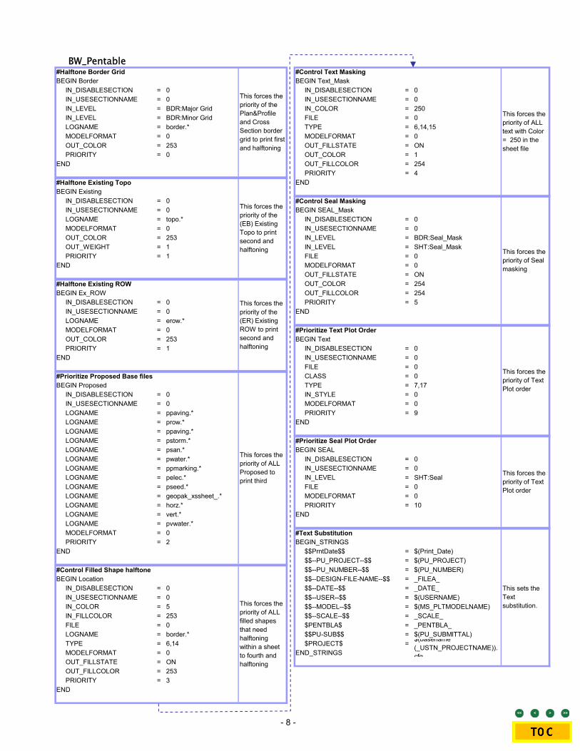
Introduction Provided in the MicroStation workspace downloads are the PW&U plot drivers. See Table 6 All printing requires one on the following Pentables. Each pentable controls print order, halftoning and text substitution. Discipline specific pentables enhance that specific discipline. Therefore it is necessary to use these specific pentables properly. The City of Lincoln provides a PENTABLE.TBL file to be included with the standard plotters. This file is located: J:\Resources\Bentley\Workspace\System\plotdrv/…
…\Resources\CityWorkspace\Standards\tables\Pen
Sheet's Directory Display Pentable \Construction and Removal (CS Construction) CR_Pentable.tbl \Details Standard BW_Pentable.tbl \General Standard BW_Pentable.tbl \Geometrics Standard BW_Pentable.tbl \Joints and Grades (JG) Joints & Grades JG_Pentable.tbl \Pavement Markings (PM) Pavement Markings PM_Pentable.tbl \Plan and Profile Standard BW_Pentable.tbl \ROW (RW) Right-of-Way RW_Pentable.tbl \Sediment and Erosion Control (EC) Sediment & Erosion EC_Pentable.tbl \Storm Drainage (SD) Storm Drainage SD_Pentable.tbl \Traffic Signal and Lighting (TS) Traffic TS_Pentable.tbl \Waste Water (WW) Waste Water WW_Pentable.tbl\Water Main (WT) Water WT_Pentable.tbl \Xsection Standard BW_Pentable.tbl Standard COLOR CO_Pentable.tbl
Table 6
The intention of the supplied pentables is to standardize the plotting output. BW_Pentable.tbl is the basis for all standard pentables. The difference between the BW_Pentable.tbl and the others is in the controlling that discipline specific output. Each discipline, when printed, should “stand out” from the rest of the sheet information.
- 8 -
BW_Pentable #Halftone Border GridBEGIN Border
IN_DISABLESECTION = 0IN_USESECTIONNAME = 0IN_LEVEL = BDR:Major GridIN_LEVEL = BDR:Minor GridLOGNAME = border.*MODELFORMAT = 0OUT_COLOR = 253PRIORITY = 0
END
#Halftone Existing TopoBEGIN Existing
IN_DISABLESECTION = 0IN_USESECTIONNAME = 0LOGNAME = topo.*MODELFORMAT = 0OUT_COLOR = 253OUT_WEIGHT = 1PRIORITY = 1
END
#Halftone Existing ROWBEGIN Ex_ROW
IN_DISABLESECTION = 0IN_USESECTIONNAME = 0LOGNAME = erow.*MODELFORMAT = 0OUT_COLOR = 253PRIORITY = 1
END
#Prioritize Proposed Base filesBEGIN Proposed
IN_DISABLESECTION = 0IN_USESECTIONNAME = 0LOGNAME = ppaving.*LOGNAME = prow.*LOGNAME = ppaving.*LOGNAME = pstorm.*LOGNAME = psan.*LOGNAME = pwater.*LOGNAME = ppmarking.*LOGNAME = pelec.*LOGNAME = pseed.*LOGNAME = geopak_xssheet_.*LOGNAME = horz.*LOGNAME = vert.*LOGNAME = pvwater.*MODELFORMAT = 0PRIORITY = 2
END
#Control Filled Shape halftoneBEGIN Location
IN_DISABLESECTION = 0IN_USESECTIONNAME = 0IN_COLOR = 5IN_FILLCOLOR = 253FILE = 0LOGNAME = border.*TYPE = 6,14MODELFORMAT = 0OUT_FILLSTATE = ONOUT_FILLCOLOR = 253PRIORITY = 3
END
This forces the priority of ALL Proposed to print third
This forces the priority of ALL filled shapes that need halftoning within a sheet to fourth and halftoning
This forces the priority of the Plan&Profile and Cross Section border grid to print first and halftoning
This forces the priority of the (EB) Existing Topo to print second and halftoning
This forces the priority of the (ER) Existing ROW to print second and halftoning
#Control Text MaskingBEGIN Text_Mask
IN_DISABLESECTION = 0IN_USESECTIONNAME = 0IN_COLOR = 250FILE = 0TYPE = 6,14,15MODELFORMAT = 0OUT_FILLSTATE = ONOUT_COLOR = 1OUT_FILLCOLOR = 254PRIORITY = 4
END
#Control Seal MaskingBEGIN SEAL_Mask
IN_DISABLESECTION = 0IN_USESECTIONNAME = 0IN_LEVEL = BDR:Seal_MaskIN_LEVEL = SHT:Seal_MaskFILE = 0MODELFORMAT = 0OUT_FILLSTATE = ONOUT_COLOR = 254OUT_FILLCOLOR = 254PRIORITY = 5
END
#Prioritize Text Plot OrderBEGIN Text
IN_DISABLESECTION = 0IN_USESECTIONNAME = 0FILE = 0CLASS = 0TYPE = 7,17IN_STYLE = 0MODELFORMAT = 0PRIORITY = 9
END
#Prioritize Seal Plot OrderBEGIN SEAL
IN_DISABLESECTION = 0IN_USESECTIONNAME = 0IN_LEVEL = SHT:SealFILE = 0MODELFORMAT = 0PRIORITY = 10
END
#Text SubstitutionBEGIN_STRINGS
$$PrntDate$$ = $(Print_Date)$$--PU_PROJECT--$$ = $(PU_PROJECT)$$--PU_NUMBER--$$ = $(PU_NUMBER)$$--DESIGN-FILE-NAME--$$ = _FILEA_$$--DATE--$$ = _DATE_$$--USER--$$ = $(USERNAME)$$--MODEL--$$ = $(MS_PLTMODELNAME)$$--SCALE--$$ = _SCALE_$PENTBLA$ = _PENTBLA_$$PU-SUB$$ = $(PU_SUBMITTAL)$PROJECT$ =
END_STRINGS
This forces the priority of ALL text with Color = 250 in the sheet file
$(basename (_USTN_PROJECTNAME)).cfg
This sets the Text substitution.
This forces the priority of Seal masking
This forces the priority of Text Plot order
This forces the priority of Text Plot order

- 9 -
CR_Pentable # Priortize Proposed Base Files
IN_DISABLESECTION = 0IN_USESECTIONNAME = 0LOGNAME = pstorm.*LOGNAME = prow .*LOGNAME = psan.*LOGNAME = pw ater.*LOGNAME = ppmarking.*LOGNAME = pelec.*LOGNAME = pseed.*LOGNAME = geopak_xssheet_.*LOGNAME = horz.*LOGNAME = vert.*MODELFORMAT = 0PRIORITY = 2
END
# Priortize Proposed Construction Base FilesBEGIN Construction
IN_DISABLESECTION = 0IN_USESECTIONNAME = 0IN_WEIGHT = 31-JanLOGNAME = ppaving.*CLASS = 0MODELFORMAT = 0OUT_WEIGHT = 6PRIORITY = 3
END
# Priortize Proposed Construction Pattern Base FilesBEGIN Construction_Pattern
IN_DISABLESECTION = 0IN_USESECTIONNAME = 0LOGNAME = quantities.*CLASS = 1MODELFORMAT = 0OUT_WEIGHT = 15PRIORITY = 3
END
This forces the priority of the Proposed Construction
Base f ile PATTERNS to print forth
This forces the priority of
ALL Proposed
Base to print third, w ith
the exception of
the Construction
Base f ile
This forces the priority of the Proposed Construction Base f ile to print forth
EC_Pentable #Prioritize Proposed Base FilesBEGIN Proposed
IN_DISABLESECTION = 0IN_USESECTIONNAME = 0LOGNAME = ppaving.*LOGNAME = pstorm.*LOGNAME = prow .*LOGNAME = psan.*LOGNAME = pw ater.*LOGNAME = ppmarking.*LOGNAME = pelec.*LOGNAME = geopak_xssheet_.*LOGNAME = horz.*LOGNAME = vert.*PRIORITY = 2
END
#Prioritize Proposed PSEED Base FilesBEGIN Seed
IN_DISABLESECTION = 0IN_USESECTIONNAME = 0LOGNAME = pseed.*CLASS = 0MODELFORMAT = 0OUT_WEIGHT = 6PRIORITY = 6
END
This forces the priority of
ALL Proposed
Base to print third, w ith
the exception of the
Erosion Control Base
f ile
This forces the priority of
Erosion Control
Proposed Base to print
Fourth
JG_Pentable #Prioritize Proposed Based filesBEGIN Proposed
IN_DISABLESECTION = 0IN_USESECTIONNAME = 0LOGNAME = pstorm.*LOGNAME = prow .*LOGNAME = psan.*LOGNAME = pw ater.*LOGNAME = ppmarking.*LOGNAME = pelec.*LOGNAME = pseed.*LOGNAME = geopak_xssheet_.*LOGNAME = horz.*LOGNAME = vert.*PRIORITY = 2
END
#Prioritize Proposed JOINTS Based f ilesBEGIN Joints
IN_DISABLESECTION = 0IN_USESECTIONNAME = 0IN_LEVEL = PP:JtsLOGNAME = ppaving.*OUT_COLOR = 253OUT_WEIGHT = 3PRIORITY = 3
END
#Prioritize Proposed GRADES Based filesBEGIN Grades
IN_DISABLESECTION = 0IN_USESECTIONNAME = 0IN_LEVEL = PP:GradesLOGNAME = ppaving.*OUT_WEIGHT = 2PRIORITY = 3
END
This forces the priority of
GRADES Proposed
Base to print Fourth
This forces the priority of
ALL Proposed
Base to print third, w ith
the exception of the
JOINTS & GRADE Base
f ile
This forces the priority of
JOINT Proposed
Base to print Fourth
PM_Pentable #Prioritize Proposed Base filesBEGIN Proposed
IN_DISABLESECTION = 0IN_USESECTIONNAME= 0LOGNAME = ppaving.*LOGNAME = pstorm.*LOGNAME = prow.*LOGNAME = psan.*LOGNAME = pwater.*LOGNAME = pelec.*LOGNAME = pseed.*LOGNAME = geopak_xssheet_.*LOGNAME = horz.*LOGNAME = vert.*PRIORITY = 2
END
#Prioritize Proposed PPMarking Base filesBEGIN Ppmarking
IN_DISABLESECTION = 0IN_USESECTIONNAME= 0LOGNAME = ppmarking.*OUT_WEIGHT = 6PRIORITY = 6
END
This forces the priority of
ALL Proposed
Base to print third, with the exception of
the Pavement Marking Base
file
This forces the priority of
Pavement Marking
Proposed Base to print
Fourth

- 10 -
RW_Pentable#Prioritize Proposed Base f ilesBEGIN Proposed
IN_DISABLESECTION = 0IN_USESECTIONNAME = 0LOGNAME = ppaving.*LOGNAME = pstorm.*LOGNAME = psan.*LOGNAME = pw ater.*LOGNAME = ppmarking.*LOGNAME = pelec.*LOGNAME = pseed.*LOGNAME = geopak_xssheet_.*LOGNAME = horz.*LOGNAME = vert.*MODELFORMAT = 0PRIORITY = 2
END
#Prioritize Proposed Base PROW Linew ork f ilesBEGIN Prow
IN_DISABLESECTION = 0IN_USESECTIONNAME = 0IN_WEIGHT = 31-JanIN_LEVEL = PR:ROWIN_LEVEL = PR:ROW TxIN_LEVEL = PR:Control AccessIN_LEVEL = PR:TEMP EsmtIN_LEVEL = PR:TEMP Esmt TxIN_LEVEL = PR:PERM Esmt TxIN_LEVEL = PR:PERM EsmtIN_LEVEL = PR:Lot NoIN_LEVEL = PR:Tract NoLOGNAME = prow .*CLASS = 0,4MODELFORMAT = 0OUT_WEIGHT = 6PRIORITY = 3
END
#Prioritize Proposed Base PROW Pattern f ilesBEGIN PROW_PATTERN
IN_DISABLESECTION = 0IN_USESECTIONNAME = 0LOGNAME = prow .*CLASS = 1,5MODELFORMAT = 0OUT_WEIGHT = 0PRIORITY = 3
END
This forces the priority of
Proposed Proposed
ROW Pattern Base to print
Fourth
This forces the priority of
ALL Proposed
Base to print third, w ith
the exception of the
Proposed ROW Base
f ile
This forces the priority of
Proposed Proposed
ROW Linew ork
Base to print Fourth
SD_Pentable#Prioritize Proposed Base f ilesBEGIN Proposed
IN_DISABLESECTION = 0IN_USESECTIONNAME = 0LOGNAME = ppaving.*LOGNAME = prow .*LOGNAME = psan.*LOGNAME = pw ater.*LOGNAME = ppmarking.*LOGNAME = pelec.*LOGNAME = pseed.*LOGNAME = geopak_xssheet_.*LOGNAME = horz.*LOGNAME = vert.*MODELFORMAT = 0PRIORITY = 2
END
#Prioritize Proposed Base PSTORM filesBEGIN Drainage
IN_DISABLESECTION = 0IN_USESECTIONNAME = 0IN_WEIGHT = 31-JanLOGNAME = pstorm.*MODELFORMAT = 0OUT_WEIGHT = 6PRIORITY = 3
END
#Prioritize Proposed Base PVSTORM filesBEGIN DrainageProfile
IN_DISABLESECTION = 0IN_USESECTIONNAME = 0LOGNAME = pstorm.*MODELFORMAT = 0PRIORITY = 3
END
This forces the priority of
ALL Proposed
Base to print third, w ith
the exception of the Storm
Drainage Base f ile
This forces the priority of
Proposed Proposed
Storm Drainage
Base to print Fourth
Forces the priority of Proposed
Storm Drainage Profile Base to
print Fourth
WW_Pentable #Prioritize Proposed Base f ilesBEGIN Proposed
IN_DISABLESECTION = 0IN_USESECTIONNAME = 0LOGNAME = ppaving.*LOGNAME = pstorm.*LOGNAME = prow .*LOGNAME = pw ater.*LOGNAME = ppmarking.*LOGNAME = pelec.*LOGNAME = pseed.*LOGNAME = geopak_xssheet_.*LOGNAME = horz.*LOGNAME = vert.*PRIORITY = 2
END
#Prioritize Proposed SANITARY Base filesBEGIN Sanitary
IN_DISABLESECTION = 0IN_USESECTIONNAME = 0LOGNAME = psan.*OUT_WEIGHT = 6PRIORITY = 6
END
This forces the priority of
ALL Proposed
Base to print third, w ith
the exception of the Waste Water Base
f ile
Forces the priority of Proposed
Waste Water to print Fourth
- 11 -
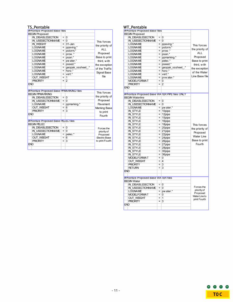
TS_Pentable#Prioritize Proposed Base f ilesBEGIN Proposed
IN_DISABLESECTION = 0IN_USESECTIONNAME = 0IN_WEIGHT = 31-JanLOGNAME = ppaving.*LOGNAME = pstorm.*LOGNAME = prow .*LOGNAME = psan.*LOGNAME = pw ater.*LOGNAME = pseed.*LOGNAME = geopak_xssheet_.*LOGNAME = horz.*LOGNAME = vert.*OUT_WEIGHT = 1PRIORITY = 2
END
#Prioritize Proposed Base PPMARKING filesBEGIN PPMARKING
IN_DISABLESECTION = 0IN_USESECTIONNAME = 0LOGNAME = ppmarking.*OUT_WEIGHT = 6PRIORITY = 3
END
#Prioritize Proposed Base PELEC filesBEGIN PELEC
IN_DISABLESECTION = 0IN_USESECTIONNAME = 0LOGNAME = pelec.*OUT_WEIGHT = 6PRIORITY = 3
END
This forces the priority of
ALL Proposed
Base to print third, w ith
the exception of the Traff ic Signal Base
f ile
This forces the priority of
Proposed Pavement
Marking Base to print Fourth
Forces the priority of Proposed
Electric Base to print Fourth
WT_Pentable #Prioritize Proposed Base f ilesBEGIN Proposed
IN_DISABLESECTION = 0IN_USESECTIONNAME = 0LOGNAME = ppaving.*LOGNAME = pstorm.*LOGNAME = prow .*LOGNAME = psan.*LOGNAME = ppmarking.*LOGNAME = pelec.*LOGNAME = pseed.*LOGNAME = geopak_xssheet_.*LOGNAME = horz.*LOGNAME = vert.*LOGNAME = pvw ater.*MODELFORMAT = 0PRIORITY = 2
END
#Prioritize Proposed Base WATER PIPE files ONLYBEGIN Waterline
IN_DISABLESECTION = 0IN_USESECTIONNAME = 0LOGNAME = pw ater.*IN_STYLE = 10pipeIN_STYLE = 12pipeIN_STYLE = 15pipeIN_STYLE = 16pipeIN_STYLE = 18pipeIN_STYLE = 20pipeIN_STYLE = 21pipeIN_STYLE = 22pipeIN_STYLE = 24pipeIN_STYLE = 26pipeIN_STYLE = 27pipeIN_STYLE = 28pipeIN_STYLE = 30pipeIN_STYLE = 36pipeMODELFORMAT = 0OUT_WEIGHT = 4PRIORITY = 3RETURN = 3
END
#Prioritize Proposed Base WATER filesBEGIN Water
IN_DISABLESECTION = 0IN_USESECTIONNAME = 0LOGNAME = pw ater.*MODELFORMAT = 0OUT_WEIGHT = 1PRIORITY = 3
END
Forces the priority of Proposed
Water Line to print Fourth
This forces the priority of
ALL Proposed
Base to print third, w ith
the exception of the Water Line Base file
This forces the priority of
Proposed Water Line
Base to print Fourth
- 12 -
Borders
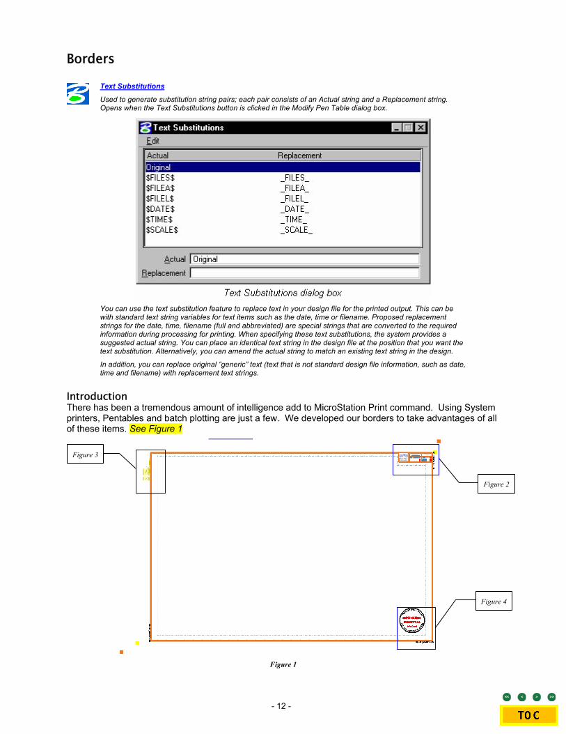
Text Substitutions
Used to generate substitution string pairs; each pair consists of an Actual string and a Replacement string. Opens when the Text Substitutions button is clicked in the Modify Pen Table dialog box.
You can use the text substitution feature to replace text in your design file for the printed output. This can be with standard text string variables for text items such as the date, time or filename. Proposed replacement strings for the date, time, filename (full and abbreviated) are special strings that are converted to the required information during processing for printing. When specifying these text substitutions, the system provides a suggested actual string. You can place an identical text string in the design file at the position that you want the text substitution. Alternatively, you can amend the actual string to match an existing text string in the design.
In addition, you can replace original “generic” text (text that is not standard design file information, such as date, time and filename) with replacement text strings.
Introduction There has been a tremendous amount of intelligence add to MicroStation Print command. Using System printers, Pentables and batch plotting are just a few. We developed our borders to take advantages of all of these items. See Figure 1
Figure 1
Figure 2
Figure 4
Figure 3

- 13 -
It is required to use the border files, listed below, as a reference attachment. These borders are provided through the BORDERS_V8.CEL library. The reason we supply the border files in both, is because of the GEOPAK Sheet Layout tool needs both to function properly. By using the borders as a reference file, whole projects can be updated rather quickly. Along with Text Substitution and halftoning, pentables will search each and every file for border references. When attaching a border file or afterwards, make certain the Logical Name is set appropriately
• BORDER_PGBK • BORDER_PLN
• BORDER_PNP • BORDER_XSEC
During the creation of sheet files, the mentioned borders are referenced to the active file. If creating sheets within GEOPAK, the GEOPAK Sheet Layout tool will assign the appropriate border as needed. See User Guide – GEOPAK Sheet Generation for further information.
Reference Manually creating a sheet file requires standardization. Begin by picking the Reference > Tool > Attach command. Select the appropriate file located under the standard directory location, …\Design\Sheets\. Logical Name should contain the word “BORDER”. Use the Default model and set the scale appropriately. No sheet file should be “rotated”. Use the MicroStation command Rotate View. This allows the user to modify their view of the sheet file. This way the sheet file will always be viewed properly and users do not develop knots in their neck. A quick check would be the City of Lincoln image in the upper right-hand corner. If this appears rotated, then there are problems.
Enhancements • Each border will have two Yellow points and two Orange points. One of each will be located in the
lower-left and upper-right corners of the border. These are used for placing fences and getting the correct scale. See Table 7
Piggy Back Plan Plan & Profile
Cross Section
Yellow 40:01:00 40:01:00 40:01:00 20:1H/10:1V Orange 20:01 20:01 20:01 10:1H/5:1V
Table 7
• Also within each sheet that correlate with the yellow and orange points are two shape set to a construction element. Batch printing will read and find the appropriate shape within each sheet and print these accordingly.
• Through out each border are MicroStation points. The most prevalent is the BORDER_PNP. These are to assist the user with placement of text, from Stationing to elevations to Sheet Numbers.
• The Title block has gone through significant changes. Each border will have these text items that include $$ --$$. By using the ProjNo.PCF file and the appropriate Pentable, there will be added intelligence to the borders. What may appear as gibberish in active view will print entirely
different. See Figure 2 o Project Numbers o Milestone Dates o Horizontal Scale o Drawing Number
Figure 2
- 14 -
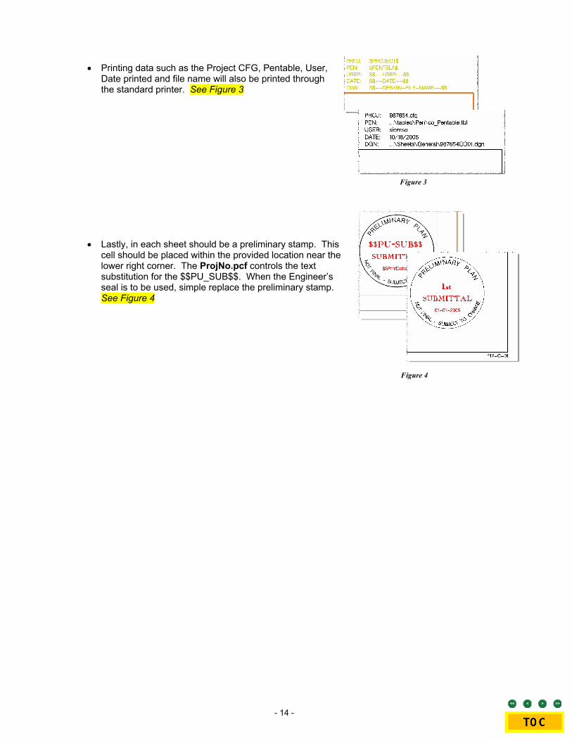
• Printing data such as the Project CFG, Pentable, User, Date printed and file name will also be printed through the standard printer. See Figure 3
Figure 3
• Lastly, in each sheet should be a preliminary stamp. This cell should be placed within the provided location near the lower right corner. The ProjNo.pcf controls the text substitution for the $$PU_SUB$$. When the Engineer’s seal is to be used, simple replace the preliminary stamp. See Figure 4
Figure 4

- 15 -
Plotting Macro
Introduction Provided in the MicroStation downloads are the various macros listed below. See Table 8 These macros are intended to give a user a straight forward command to get what they need.
Description These macros are rather simple key in commands disguised as MicroStation programming. Simply put, these commands request the user to “Place a Fence”. Upon placing a fence, the macro loads everything needed to complete the printing process. Next, loads the appropriate Print Drive. Followed by Attaching the necessary discipline specific Pentable. Finally, the macro opens the Print Dialog box ready to print.
Macro Print Driver Pentable HP1050c_BW.bas Hp1050C sieip04 B&W.plt BW_pentable.tbl HP1050c_CO.bas Hp1050C sieip04 CO.plt CO_pentable.tbl Konica03_BW.bas KONICA_03.plt CW_pentable.tbl Konica03_CR.bas KONICA_03.plt CR_pentable.tbl Konica03_EC.bas KONICA_03.plt EC_pentable.tbl Konica03_JG.bas KONICA_03.plt JG_pentable.tbl Konica03_PH.bas KONICA_03.plt PH_pentable.tbl Konica03_PM.bas KONICA_03.plt PM_pentable.tbl Konica03_PZ.bas KONICA_03.plt BW_pentable.tbl Konica03_RW.bas KONICA_03.plt RW_pentable.tbl Konica03_SD.bas KONICA_03.plt SD_pentable.tbl Konica03_TS.bas KONICA_03.plt TS_pentable.tbl Konica03_WT.bas KONICA_03.plt WT_pentable.tbl Konica03_WW.bas KONICA_03.plt WW_pentable.tbl Konica05_STD.bas KONICA_05c.plt CO_pentable.tbl PDF_BW.bas PDF B&W.plt CW_pentable.tbl PDF_CO.bas PDF Color.plt CO_pentable.tbl PDF_CR.bas PDF B&W.plt CR_pentable.tbl PDF_EC.bas PDF B&W.plt EC_pentable.tbl PDF_JG.bas PDF B&W.plt JG_pentable.tbl PDF_PH.bas PDF B&W.plt PH_pentable.tbl PDF_PM.bas PDF B&W.plt PM_pentable.tbl PDF_PZ.bas PDF B&W.plt BW_pentable.tbl PDF_RW.bas PDF B&W.plt RW_pentable.tbl PDF_SD.bas PDF B&W.plt SD_pentable.tbl PDF_TS.bas KONICA_03.plt TS_pentable.tbl PDF_WT.bas KONICA_03.plt WT_pentable.tbl PDF_WW.bas KONICA_03.plt WW_pentable.tbl
Table 8
- 16 -
Batch Plot
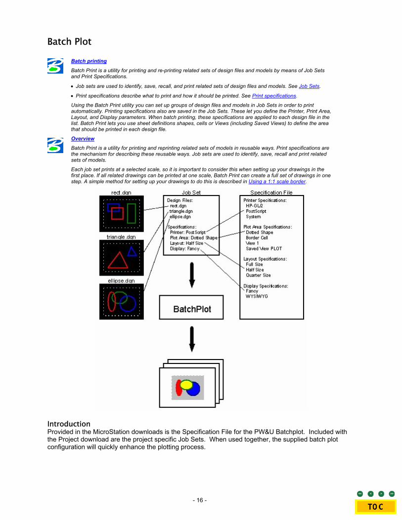
Batch printing
Batch Print is a utility for printing and re-printing related sets of design files and models by means of Job Sets and Print Specifications.
• Job sets are used to identify, save, recall, and print related sets of design files and models. See Job Sets.
• Print specifications describe what to print and how it should be printed. See Print specifications.
Using the Batch Print utility you can set up groups of design files and models in Job Sets in order to print automatically. Printing specifications also are saved in the Job Sets. These let you define the Printer, Print Area, Layout, and Display parameters. When batch printing, these specifications are applied to each design file in the list. Batch Print lets you use sheet definitions shapes, cells or Views (including Saved Views) to define the area that should be printed in each design file.
Overview
Batch Print is a utility for printing and reprinting related sets of models in reusable ways. Print specifications are the mechanism for describing these reusable ways. Job sets are used to identify, save, recall and print related sets of models.
Each job set prints at a selected scale, so it is important to consider this when setting up your drawings in the first place. If all related drawings can be printed at one scale, Batch Print can create a full set of drawings in one step. A simple method for setting up your drawings to do this is described in Using a 1:1 scale border.
Introduction Provided in the MicroStation downloads is the Specification File for the PW&U Batchplot. Included with the Project download are the project specific Job Sets. When used together, the supplied batch plot configuration will quickly enhance the plotting process.

- 17 -
Printer Specification
Using Print Specifications
Print specifications control the following aspects of printing:
• Printer (see Printer Specifications)
• Print Area (see Print Area specifications)
• Layout (see Layout specifications)
• Display (see Display specifications)
Using print specifications you can set up a system for printing the drawings for a particular project. Once set up, you do not need to enter the drawing file to create a print of it. You can produce a print of one or more drawings via Batch Print.
Managing Print Specifications
Using the Batch Print Specification Manager dialog box, you can create, copy, rename, and delete print specifications.
Introduction A Printer specification selects a MicroStation printer driver, a paper size, a paper orientation and specifies post-processing options LINCOLNV851.CFG: Line 135 MS_BATCHPLT_SPECS= $(_CITY_STANDARD)Data/batchplt.spc

- 18 -
Figure 5
BATCHPLT.SPC
• 11x17 PDF • 85x11 PDF • EMF • KONICA03
• 11x17 • 85x11
• Maximize
Print Attributes • Camera: OFF • Fast Fonts: OFF • Print Border: OFF • Construction: OFF • Fence Boundary: OFF • Ref Boundaries:OFF • Data Fields: OFF • Fill: ON • Tages: OFF • Dimensions: ON • Level Symbology: OFF • Text: ON • Displayset: As-is • Line Styles: On • Text Nodes: OFF • Fast Cells: OFF • Patterns: ON • Broken Association Symb: As-is • Fast Curves: OFF Pen Table Additional Options Filename: varies • Color Mode: As-is
• Construction • Erosion Control • Joints • Pavement Marking • Phasing • ROW • Standard • Standard Color • Storm Drainage • Traffic • Waste Water • Water Main
Erosion Control Pen Table Filename: ec_pentable.tbl
Joints Pen Table Filename: jg_pentable.tbl
Pavement Marking Pen Table Filename: pm_pentable.tbl
Phasing Pen Table Filename: ph_pentable.tbl
ROW Pen Table Filename: rw_pentable.tbl
Standard Pen Table Filename: bw_pentable.tbl
Standard Color Pen Table Filename: co_pentable.tbl
Storm Drainage Pen Table Filename: sd_pentable.tbl
Traffic Pen Table Filename: ts_pentable.tbl
Waste Water Pen Table Filename: ww_pentable.tbl
Water Main Pen Table Filename: wl_pentable.tbl
Printers Print Area Layout Display
Construction Pen Table Filename: cr_pentable.tbl

- 19 -
Batch Job Set
Job Sets
A job set is an ordered list of design files to be printed, along with references to the print specifications that control how they are printed. Job sets are stored in job set files (.job) with arbitrary names and locations. For example, a job set file named “myhouse.job” might represent the set of plans, elevations and detail sheets for a particular house. It lists all the master design files representing those plans, elevations and detail sheets, as well as the names of the specifications describing how they should be printed.
Batch Print lets you reassign the specifications assigned to a job set at any time, making it easy to print variations of the set. Files can be added, deleted or moved up or down within the job set.
Introduction Batch Print lets you reassign the specifications assigned to a job set at any time, making it easy to print variations of the set. Files can be added, deleted or moved up or down within the job set. ProjNo.PCF: Line 49 MS_BATCHPLT_JOBSET_DIR = $(Plot)
OUTPUT FORMAT Direct Print PDF Print aConstruction.job PDF Construction.job ...\Sheets\Construction and Removal\*.dgn aErosion.job PDF Erosion.job ...\Sheets\Sediment and Erosion Control\*.dgn aGeometrics.job PDF Geometrics.job ...\Sheets\Geometrics\*.dgn aJoints.job PDF Joints.job ...\Sheets\Joints and Grades\*.dgn aMisc.job PDF Misc.job ...\Sheets\Details\*.dgn & ...\Sheets\General\*.dgn aPavtMarking.job PDF PavtMarking.job ...\Sheets\Pavement Marking\*.dgn aPhasing.job PDF Phasing.job ...\Sheets\General\*.dgn aPlan&Profile.job PDF Plan&Profile.job ...\Sheets\Plan&Profile\*.dgn aROW.job PDF ROW.job ...\Sheets\ROW\*.dgn aStorm.job PDF Storm.job ...\Sheets\Storm Drainage\*.dgn aStorm.job PDF Traffic Signal.job ...\Sheets\Traffic Signals and Lighting\*.dgn aWasteWater.job PDF WasteWater.job ...\Sheets\Waste Water\*.dgn aWater.job PDF Water.job ...\Sheets\Water Main\*.dgn aXsection.job PDF Xsection.job ...\Sheets\XSection\*.dgn
Table 9

- 20 -
Logical Naming
Introduction A single MicroStation model or AutoCAD file can be attached to the current active model several times. MicroStation V8.5 distinguishes the different attachment instances by using a “logical name.” LPW&U also uses the logical name of a reference file to control plotting parameters such as gray scaling specific information of a sheet file that is in a reference file. Use the Logical Name Prefix listed in Table 10 as a prefix to the Logical Name defined in the “Attach Reference Settings” dialog box.
Standard Base File Naming Convention Each of the file names will follow a consistent naming convention following this example:
Table 10
Base Files Description Logical Name 123456 ER 00.dgn EXIST. RIGHT-OF-WAY EROW 123456 PR 00.dgn PROP. RIGHT-OF-WAY PROW 123456 PP 00.dgn PROP. PAVING PPAVING 123456 PD 00.dgn PROP. STORM DRAINAGE PSTORM 123456 VD 00.dgn PROP. STORM DRAINAGE – VERTICAL PvSTORM 123456 PS 00.dgn PROP. WASTE WATER PSAN 123456 VS 00.dgn PROP. WASTE WATER-VERTICAL PvSAN 123456 PW 00.dgn PROP. WATER PWATER 123456 VW 00.dgn PROP. WATER – VERTICAL PvWATER 123456 PM 00.dgn PROP. PAVEMENT MARKINGS AND SIGNS PPMARKING 123456 PE 00.dgn PROP. ELECTRICAL PELEC 123456 PH 00.dgn PROP. HORIZONTAL ALIGNMENT HORZ 123456 VH 00.dgn PROP./EXIST. VERTICAL ALIGNMENT VERT 123456 PG 00.dgn PROP. GEOPAK PATTERN 123456 PX 00.dgn PROP X-SECTION (BASE) 123456 PZ 00.dgn REMOVAL QUANTITIES REMOVAL 123456 PQ 00.dgn PROP. QUANTITIES 123456 PC 00.dgn PROP. SEDIMENT AND EROSION CONTROL PSEED 123456 EB 00.dgn EXIST. TOPO (SURVEY BASE) TOPO 123456 PT 00.dgn PROP. TRAFFIC CONTROL PTRAFFIC 123456 PF 00.dgn PROP. CONSTRUCTION PHASING PPHASING 123456 WK_2D.dgn Working File 2D - NOT USED FOR PRODUCTION 123456 WK_3D.dgn Working File 3D - NOT USED FOR PRODUCTION
Time Charge Number File Abbr.
Number
File Type
File: Exist./ Prop.
123456 XX 00.dgn
NOTE: For archiving purpose, use progressive numbering from 00 to 99, keeping 00 the most current. Exception would be the Cross Section base file. The major roadway will be 00 and smaller, lesser roadways will follow.

- 21 -
PDF Composer
Introduction to MicroStation PDF Composer
MicroStation PDF Composer is a Windows application for publishing PDF documents from plots and plot sets. MicroStation PDF Composer can publish PDF documents from drawing sets in a single step.
Using PDF Composer's Design Script extensions, you can publish PDF documents that contain audio or video instructions, bookmarks, internal PDF document links, Web URL Links, and attachments that contain project specifications. PDF Composer's configuration command enables you to publish PDF documents that contain Engineering Links, Searchable text, and Levels/Files (Optional Content). Including Levels/Files (Optional Content) in the PDF file enables users to turn on/off levels and references when viewing the file.
Introduction The City is currently looking into and developing procedures for the PDF Composer software. There will be more information in the future.

- 22 -
This page left blank intentionally