CADD Editing Manual - North Dakota Department of Transportation

CADD Manual In reference to the FDOT Design Manual (FDM)
TOPIC NUMBER: 625-050-001
Publish Date: April 5, 2018
PRODUCTION SUPPORT CADD OFFICE TALLAHASSEE, FLORIDA
http://www.fdot.gov/cadd/
State of Florida
Department of Transportation

[THIS PAGE INTENTIONALLY LEFT BLANK]

i
Contents
TOPIC NUMBER: 625-050-001 ............................................................................................................................ 1-1
.......................................................................................................................................................... 1-1
INTRODUCTION .................................................................................................................................................. 1-1
1.1 PURPOSE .......................................................................................................................................................... 1-1 1.2 AUTHORITY ...................................................................................................................................................... 1-1 1.3 SCOPE .............................................................................................................................................................. 1-1 1.4 DEFINITIONS .................................................................................................................................................... 1-1 1.5 ORGANIZATION ............................................................................................................................................... 1-7 1.6 REFERENCES .................................................................................................................................................... 1-7 1.7 ROLES AND RESPONSIBILITIES ......................................................................................................................... 1-8
CADD Office .............................................................................................................................................. 1-8 CADD Managers ....................................................................................................................................... 1-8 CADD Technical Advisory Committees (TACs) .......................................................................................... 1-8
.............................................................................................................................................................................. 1-9 1.8 DISTRIBUTION .................................................................................................................................................. 1-9 1.9 TRAINING ......................................................................................................................................................... 1-9 1.10 LINKS AND FORMS ......................................................................................................................................... 1-9
CADD Quick Links ................................................................................................................................... 1-9 Suggestions, Comments, or Questions for the CADD Manual ............................................................. 1-10 Compliance Certification Checklist ......................................................................................................... 1-1
.......................................................................................................................................................... 2-1
CADD COMPUTER SYSTEMS ................................................................................................................................ 2-1
2.1 PURPOSE .......................................................................................................................................................... 2-1 2.2 SCOPE .............................................................................................................................................................. 2-1 2.3 PROCUREMENT OF CADD HARDWARE AND SOFTWARE ................................................................................. 2-1 2.4 MINIMUM SYSTEM REQUIREMENTS ............................................................................................................... 2-1 2.5 OPTIMAL CADD HARDWARE AND SOFTWARE REQUIREMENTS ...................................................................... 2-1
.......................................................................................................................................................... 3-1
CADD SOFTWARE, DEVELOPMENT AND DISTRIBUTION ...................................................................................... 3-1
3.1 PURPOSE .......................................................................................................................................................... 3-1 3.2 SCOPE .............................................................................................................................................................. 3-1 3.3 SUPPORTED CADD PLATFORMS ....................................................................................................................... 3-1 3.4 DEVELOPMENT ................................................................................................................................................ 3-1
Development or Acquisition ..................................................................................................................... 3-2 3.5 CADD SOFTWARE AND UPDATES ..................................................................................................................... 3-2
CADD Software Testing ............................................................................................................................ 3-2 CADD Software Releases .......................................................................................................................... 3-2 CADD Software Distribution and Downloads ........................................................................................... 3-2
.......................................................................................................................................................... 4-1
CADD SUPPORT .................................................................................................................................................. 4-1
(CUSTOMER SUPPORT GUIDE) ............................................................................................................................ 4-1
4.1 PURPOSE .......................................................................................................................................................... 4-1 4.2 SCOPE .............................................................................................................................................................. 4-1 4.3 OVERVIEW ....................................................................................................................................................... 4-1 4.4 SYSTEM SUPPORT ............................................................................................................................................ 4-2
Hierarchy of Systems Support .................................................................................................................. 4-2 4.5 OPERATIONAL SUPPORT .................................................................................................................................. 4-2

ii
Hierarchy of Operational Support ............................................................................................................ 4-2 Reporting of CADD Issues ......................................................................................................................... 4-3
4.6 TRAINING SUPPORT ......................................................................................................................................... 4-4
.......................................................................................................................................................... 5-1
CADD PROJECT DEVELOPMENT PROCESSES ........................................................................................................ 5-1
5.1 PURPOSE .......................................................................................................................................................... 5-1 5.2 SCOPE .............................................................................................................................................................. 5-1 5.3 PROJECT DEVELOPMENT & ENVIRONMENT .................................................................................................... 5-1
Project CADD Deliverables ....................................................................................................................... 5-1 5.4 RIGHT OF WAY MAPPING ................................................................................................................................ 5-2
Project CADD Deliverables ....................................................................................................................... 5-2 5.5 SURVEY ............................................................................................................................................................ 5-3
Project CADD Deliverables ....................................................................................................................... 5-3 Data File Created by Surveying ................................................................................................................ 5-3 FDOT Standard Survey Feature Tables ..................................................................................................... 5-4
5.5.3.1 FDOT Standard Field Survey Zones for Points & Linear Features / Figures .......................................................... 5-4 5.5.3.2 Survey Feature Codes .......................................................................................................................................... 5-4 5.5.3.3 Application Feature Tables .................................................................................................................................. 5-4
Survey Cell Libraries ................................................................................................................................. 5-6 Feature List files ....................................................................................................................................... 5-6 Translation Table ..................................................................................................................................... 5-6 County Mapping ....................................................................................................................................... 5-7 Utility Quality Levels ................................................................................................................................ 5-8
5.6 GEOTECHNICAL ................................................................................................................................................ 5-9 5.7 TRAFFIC DATA .................................................................................................................................................. 5-9 5.8 TYPICAL SECTIONS PACKAGE ........................................................................................................................... 5-9 5.9 DRAINAGE ...................................................................................................................................................... 5-10 5.10 TRAFFIC CONTROL PLAN .............................................................................................................................. 5-10 5.11 PAVEMENT .................................................................................................................................................. 5-10 5.12 UTILITIES ...................................................................................................................................................... 5-10
.......................................................................................................................................................... 6-1
CADD STANDARDS .............................................................................................................................................. 6-1
6.1 PURPOSE .......................................................................................................................................................... 6-1 6.2 SCOPE .............................................................................................................................................................. 6-1 6.3 GENERAL .......................................................................................................................................................... 6-1 6.4 3D MODELING STANDARDS ............................................................................................................................. 6-2
Corridor Frequency Interval Spacing for 3D Design ................................................................................. 6-2 6.5 DATABASE (DDB) RESOURCES .......................................................................................................................... 6-2
MicroStation ............................................................................................................................................ 6-2 AutoCAD ................................................................................................................................................... 6-3
6.6 SEED / SHEET TEMPLATE FILES ......................................................................................................................... 6-3 MicroStation Seed Files ............................................................................................................................ 6-3 AutoCAD Sheet Template Files ................................................................................................................. 6-4
6.7 STANDARD DESIGN LIBRARIES / TEMPLATES ................................................................................................... 6-5 MicroStation Design Libraries .................................................................................................................. 6-5 AutoCAD Design Template Files ............................................................................................................... 6-6
6.8 CELL LIBRARIES / BLOCK DRAWINGS ................................................................................................................ 6-6 6.9 STANDARD FILE NAMES ................................................................................................................................... 6-8
Standard Design File Naming Convention ................................................................................................ 6-8 6.9.1.1 Structures Standard Design File Naming Convention .......................................................................................... 6-9 6.9.1.2 Architectural Standard Design File Naming Convention .................................................................................... 6-10 6.9.1.3 Architectural Standard Sheet Naming Convention ............................................................................................ 6-11
Standard Design Filename Tables .......................................................................................................... 6-13
iii
Typical File Name Extensions ................................................................................................................. 6-13 6.10 STANDARD CADD RULES .............................................................................................................................. 6-15
CADD Standard Rule Tables ................................................................................................................. 6-16 Exceptions to the Standard Rules......................................................................................................... 6-16
6.11 STANDARD CADD LEVELS / LAYERS .............................................................................................................. 6-16 Levels / Layers Naming & Designation Convention ............................................................................. 6-16
6.11.1.1 Structures Standard Level / Layer and Symbology .......................................................................................... 6-17 6.11.1.2 Architectural Level/Layers and Symbology ..................................................................................................... 6-18 6.11.1.3 Survey Level / Layer and Symbology Standards .............................................................................................. 6-19
Minimum Requirement for Percentage of Compliance........................................................................ 6-19 6.12 STANDARD CADD SYMBOLOGY ................................................................................................................... 6-19
Color ..................................................................................................................................................... 6-19 6.12.1.1 Structures Colors ............................................................................................................................................. 6-20
Line Styles / Linetypes (Standard Symbols) .......................................................................................... 6-20 6.12.2.1 Custom Line Styles/Linetypes (Standard Symbols) Table ................................................................................ 6-21
Line Weight .......................................................................................................................................... 6-22 6.13 TEXT ............................................................................................................................................................. 6-23
True Type Fonts (TTF) ........................................................................................................................... 6-23 6.13.1.1 Structures Special Symbols .............................................................................................................................. 6-24
Text Size and Spacing ........................................................................................................................... 6-24 6.13.2.1 Architectural Text Type, Size and Line Weight ................................................................................................ 6-25 6.13.2.2 Structures Text Sizes and Weights ................................................................................................................... 6-26
6.14 STANDARD ABBREVIATIONS ........................................................................................................................ 6-26 6.15 SHEET NUMBERS ......................................................................................................................................... 6-27 6.16 PRINTS ......................................................................................................................................................... 6-28
Print Drivers ......................................................................................................................................... 6-28 6.16.1.1 MicroStation Half-Toning ................................................................................................................................ 6-28 6.16.1.2 Quality and Reproduction ............................................................................................................................... 6-28
Print Resource Files .............................................................................................................................. 6-29 6.16.2.1 MicroStation .................................................................................................................................................... 6-29 6.16.2.2 AutoCAD Civil 3D ............................................................................................................................................. 6-30
Print Borders ........................................................................................................................................ 6-30 Print Image Files .................................................................................................................................. 6-30
6.16.4.1 Print Image File Naming Convention ............................................................................................................... 6-30 6.16.4.2 Print Image File Naming Format ...................................................................................................................... 6-31
.......................................................................................................................................................... 7-1
CADD PRODUCTION ............................................................................................................................................ 7-1
7.1 PURPOSE .......................................................................................................................................................... 7-1 7.2 SCOPE .............................................................................................................................................................. 7-1 7.3 ACCOUNTABILITY ............................................................................................................................................. 7-1 7.4 PRE-PRODUCTION ........................................................................................................................................... 7-1
Create Project........................................................................................................................................... 7-1 Standard Project Folder ........................................................................................................................... 7-2
7.4.2.1 Standard Project Folder Structure ....................................................................................................................... 7-2 7.5 PRODUCTION ................................................................................................................................................... 7-5 7.6 SUPPORTED SOFTWARE BY CONTRACT PLANS SET COMPONENTS ................................................................. 7-6
Roadway .................................................................................................................................................. 7-6 7.6.1.1 GEOPAK, OPENROADS, CIVIL3D ........................................................................................................................... 7-6
Signing and Pavement Marking ............................................................................................................... 7-6 7.6.2.1 Sign Design........................................................................................................................................................... 7-6 7.6.2.2 Turn Radius Design .............................................................................................................................................. 7-7
Signalization ............................................................................................................................................. 7-7 Intelligent Transportation Systems .......................................................................................................... 7-7 Lighting .................................................................................................................................................... 7-7
7.6.5.1 Lighting Design Software ..................................................................................................................................... 7-7 Landscape ................................................................................................................................................ 7-8

iv
Architectural ............................................................................................................................................ 7-8 7.6.7.1 Architectural Adopted CADD File Format ............................................................................................................ 7-9 7.6.7.2 Architectural Adopted CADD Standards .............................................................................................................. 7-9 7.6.7.3 Architectural Projects .......................................................................................................................................... 7-9 7.6.7.4 Delineation between Architectural & Engineering Plans ................................................................................... 7-10 7.6.7.5 Architectural Scale Chart ................................................................................................................................... 7-11
Structures ............................................................................................................................................... 7-11 7.6.8.1 Structures Borders and Scales ........................................................................................................................... 7-12 7.6.8.2 Structures Dimension Settings ........................................................................................................................... 7-13 7.6.8.3 Existing Bridge Plans .......................................................................................................................................... 7-13
Toll Facilities ........................................................................................................................................... 7-13 7.7 REFERENCE FILES ........................................................................................................................................... 7-14
MicroStation Referencing ...................................................................................................................... 7-14 AutoCAD Referencing ............................................................................................................................. 7-14 Sharing of CADD Files ............................................................................................................................. 7-15
7.8 PROJECT JOURNAL ......................................................................................................................................... 7-15 7.9 EXISTING AS BUILT PLAN SHEETS ................................................................................................................... 7-15 7.10 PROFESSIONAL OF RECORD NOTE ............................................................................................................... 7-16
.......................................................................................................................................................... 8-1
CADD DELIVERY .................................................................................................................................................. 8-1
8.1 PURPOSE .......................................................................................................................................................... 8-1 8.2 SCOPE .............................................................................................................................................................. 8-1 8.3 RECEIPT AND ACCEPTANCE OF ELECTRONIC DATA .......................................................................................... 8-1 8.4 PRODUCTION DELIVERABLE FILES .................................................................................................................... 8-2
Plans Component PDF Files ...................................................................................................................... 8-2 8.4.1.1 Early Work Sheets of Plan Sets ............................................................................................................................ 8-3 8.4.1.2 Plans Component PDF Deviation ......................................................................................................................... 8-3
3D Model PDF Files .................................................................................................................................. 8-4 Specifications PDF Files ............................................................................................................................ 8-4 CAD ZIP Files ............................................................................................................................................. 8-4
8.4.4.1 Engineering Data ................................................................................................................................................. 8-5 8.4.4.2 3D Deliverables - Automated Machine Guidance in Construction ...................................................................... 8-5
Merging External Project Files ................................................................................................................. 8-7 Reviewing the Project .............................................................................................................................. 8-7 Sign and Seal Project Files ........................................................................................................................ 8-8
8.4.7.1 Digital Certificates................................................................................................................................................ 8-9 8.4.7.2 Multiple Signature Sheets .................................................................................................................................... 8-9 8.4.7.3 Securing the Project for Delivery ......................................................................................................................... 8-9
Legacy Electronic Signature Projects...................................................................................................... 8-10 Media Requirements for Delivery .......................................................................................................... 8-10
Compliance Certification Checklist ....................................................................................................... 8-10 8.5 SPECIFICATIONS ............................................................................................................................................. 8-11 8.6 FINAL PLANS OFFICE ...................................................................................................................................... 8-13 8.7 REVISIONS ...................................................................................................................................................... 8-14 8.8 RE-LET PROJECTS AND ROLL BACK REVISIONS ............................................................................................... 8-14 8.9 STRUNG PROJECTS ......................................................................................................................................... 8-14 8.10 AS-BUILT PROJECTS ..................................................................................................................................... 8-15 8.11 DESIGN BUILD PROJECTS ............................................................................................................................. 8-15 8.12 PROJECT STORAGE AND ARCHIVAL.............................................................................................................. 8-15

v
.......................................................................................................................................................... 9-1
QUALITY ASSURANCE AND QUALITY CONTROL ................................................................................................... 9-1
9.1 PURPOSE .......................................................................................................................................................... 9-1 9.2 AUTHORITY ......................................................................................................................................................... 9-1 9.3 QA MONITORING PLAN......................................................................................................................................... 9-1 9.4 ACCOUNTABILITY .................................................................................................................................................. 9-2 9.5 ANNUAL QUALITY ASSURANCE REVIEWS (QAR) ......................................................................................................... 9-2 9.6 AUTOMATED QUALITY CONTROL (QC) SOFTWARE...................................................................................................... 9-2

vi
[THIS PAGE INTENTIONALLY LEFT BLANK]
CADD Manual Publish Date: April 5, 2018
Topic No. 625-050-001
1-1
INTRODUCTION
1.1 PURPOSE
The CADD Manual addresses the requirements to utilize Computer Aided Design and Drafting (CADD) for
production and delivery of digital project data for the Florida Department of Transportation (Department). In
addition to software and configuration requirements, it identifies tools, techniques, applications, standards and
procedures that are used to produce a consistent and quality CADD product for the Department.
The CADD Manual establishes minimum CADD standards to ensure a consistent, predicable and repeatable
CADD data set for Department’s projects. The CADD Manual also serves to provide professional services
administrators, project managers, consultants, in-house designers, and others a procedure to be incorporated by
reference into scopes and other contract documents for services.
1.2 AUTHORITY
Florida Statutes (F.S.), Title IV, Chapter 20, Section 20.23(3) (a)
Florida Statutes (F.S.), Title XXVI, Chapter 334, Section 334.048(3)
1.3 SCOPE
The CADD Manual is to be used by all personnel producing projects utilizing CADD for the Department. It is
to be referenced in contracts requiring engineering plans and 3D Models preparation utilizing CADD. This
manual affects all offices of the Department and all consultants, contractors and others who utilize CADD
applications. The Districts are monitored for critical requirement to meet the Department’s CADD Quality
Assurance objectives.
1.4 DEFINITIONS
The following definitions used in the CADD Manual relate to electronically generated project data and
deliverables for consistency of understanding and interpretation of processes and criteria contained within.
3D Design: The process of creating 3D Models for a project.
3D Engineered Model Quality Control Checklist: A draft document that contains the data producers’ written
assurances that the 3D deliverable items required by the Department’s CADD Manual are included in the
delivered project data and that certain Quality Control functions were performed.
3D Model: A 3D model is a digital graphical representation of proposed facility/site data consisting of X, Y,
and Z coordinates for producing objects in three dimensions to communicate design intent useful for
visualization, analysis, animation, simulation, plans, specifications, estimates production, and life-cycle asset
management. An accurately designed 3D model will be tied to a defined coordinate system.
Alpha Testing: Initial testing of CADD software products or enhancements by the development staff and
testing by the support staff outside of the development environment.

CADD Manual Publish Date: April 5, 2018
Topic No. 625-050-001
1-2
Authentication: For Digital Signature, Authentication is the process where Digital Signatures are compared
with identity data held by the issuer of a Digital Certificate (the Certificate Authority) to validate the identify
of a Signatory; and that a document that has been signed with a Digital Signature has not been modified since
signing. This is an automated process of the document software (such as with Adobe Reader or Acrobat) that
provides feedback to the user that the file being examined is signed, the signatures are valid, and the document
is unmodified since the Signatory signed it.
Automated Machine Guidance (AMG): Automated machine guidance is a process in which construction
equipment is linked directly to the operation of machinery with a high level of precision, improving the speed
and accuracy of construction processes. The AMG can utilize the GPS or robotic total stations for positioning
information.
Beta Testing Coordinator: An individual responsible for facilitating the beta testing of CADD software.
Beta Testing: Secondary testing of CADD software products performed in a production-like environment by
end-users.
Bid Set: A sub-set of files consisting of data derived from the overall Project Data Set containing only those
files needed for the advertisement and letting of a project. The files needed for the Bid Set remain in their
source folder structure derived from the Project Data set. For Digital Delivery projects, the data in the Bid Set
is usually compiled manually and put in a ZIP file with a naming convention defined later in this chapter.
ByLayer (AutoCAD)– A property that, when turned on, causes the object on a particular layer to retrieve its
definition from the Layer Properties of that layer, such as Color, Linetype, and Line weight.
ByLevel (MicroStation)– A setting that, when turned on, causes the element on a particular level to retrieve
its definition from the Level Symbology of that layer, such as Color, Line Style, and Line Weight defined by
the Level Symbology.
CADD - (Acronym for: Computer Aided Design and Drafting) Software and methods used to design and
represent objects graphically on the computer. CADD facilitates the visual presentation of Engineering Data.
CADD Community: The CADD Community encompasses all CADD users, (i.e. department, consultants,
contractors, and other agencies) utilizing Department supported CADD platforms and custom software.
CADD Hardware: The workstations, servers, printers and all other computer equipment used in the
Department’s design production effort.
CADD Manager - The CADD Manager is responsible for (1) support of the core CADD software products in
the work units and (2) a variety of Final Plans functions including but not limited to the receipt, acceptance,
and management of digital deliveries of project data.
CADD Production: The development of projects utilizing CADD applications, software and discipline-based
processes.
CADD Software: Any software procured, developed, distributed and supported by CADD.
CADD Support - The technical and operational activity necessary to ensure that a production environment is
maintained, which includes:
a) Selection, development and distribution of production CADD software, related procedures, criteria and
standard operating instructions,
b) Provision of training opportunities for CADD users,
c) Management of design data produced with the CADD software,
d) Statewide procurement of: CADD software, training services, and software development assistance.
CADD TAC - (Acronym for: Computer Aided Design and Drafting Technical Advisory Committee) A
discipline-based group sanctioned by the Statewide CADD Coordinator consisting of District and Central
Office representatives charged to meet and work on statewide technical issues dealing with CADD
applications, procedures, testing, training, and implementation.
Calculations Folder: Excel files, Portable Document Format (PDF) files and any associated quantity backup
data for the plan summary boxes.
Certificate Authority: The 3rd party entity that issues the Digital Certificate to the professional signatory and
validates the identity of the signatory.

CADD Manual Publish Date: April 5, 2018
Topic No. 625-050-001
1-3
Compliance Certification Checklist: A draft document that contains the data producers’ written assurances
that items required by the Department’s CADD Manual are included in the delivered project data and that
certain Quality Control functions were performed.
Compliance Indicator: Evidence that the critical requirements which are being applied are producing the
desired result.
Component – A categorization of design plans as defined in the FDOT Design Manual (FDM) 302.5. The
list of plans components for Digital Delivery is comprised of the following:
1. Roadway
2. Signing and Pavement Marking
3. Signalization
4. Intelligent Transportation System (ITS)
5. Lighting
6. Landscape
7. Architectural
8. Structures
9. Toll Facilities
The plans components do not directly correspond to the project’s folder structure. For example, drainage files
have a \drainage\ folder below the root level project folder, but might be included as part of the Roadway
Plans Component.
Composite PDF: A document containing the plan sheet images composing the plans set in their index order.
This document must be in Adobe Portable Document Format (PDF) format and reside in the project's root
folder.
Design File – An electronic CADD file that conforms to MicroStation® (DGN) or AutoCAD® (DWG)
graphics formats.
Design Quantities and Estimates System (DQE). An application for FDOT Estimators used to produce
Construction Cost Estimates. It is also used to maintain pay items and the Basis of Estimates.
Digital Certificate: In cryptography, a digital certificate uses a digital signature to bind together a public key
with an identity — information such as the name of a person or an organization, their address, and so forth.
The certificate can be used to verify that a public key belongs to an individual. The signatures on a certificate
are attestations by the certificate signer that the identity information and the public key belong together.
The type of Digital Certificates used for the Department’s design work must meet the Federal Government’s
Access Certificates for Electronic Services (ACES) program. The Department currently uses IdenTrust to
provide those digital certificates: http://www.identrust.com/government/index.html
Digital Delivery: A method to deliver project data which relies upon creating a compressed archive (ZIP file)
of project data, PDF files of Plans and Specifications documents. Plans and Specifications are signed and sealed
with a Digital Signature.
Digital Signature Appearance: A graphical representation that appears on an electronic document indicating
that a digital signature has been applied. As a minimum, the appearance must contain the name of the signatory
and a date-time stamp at the instant of signature. When a digital signature is used as an application of a
professional’s signature and seal, specific language must accompany the digital signature appearance. See the
Department’s FDM 303 Exhibits for further explanation and examples. When the digital signature is an
application of a professional engineer’s signature and seal, The Signature Appearance is not proof of
authenticity, only that a signature was applied. Authenticity is proven through the Validation process (see
Validation definition).
Digital Signature: Cryptographic data applied to an electronic file which is unique to the signatory, and is
very difficult to forge. In addition, the digital signature assures that any changes made to the data or electronic
file that has been signed cannot go undetected. A Digital Signature is much the same as a conventional
handwritten signature that identifies a person signing the document. While traditional signatures are on paper,
every digital signature stores information that will identify the person signing. There can also be information
about changes made to a digitally signed document since the first signature was applied. In Digital Delivery,
Digital Signatures are applied to Signature Sheet(s) in the plans or may be applied to documents that
Professional(s) of Records are taking responsibility for.

CADD Manual Publish Date: April 5, 2018
Topic No. 625-050-001
1-4
Digital Signature Root Certificate: Cryptographic information installed on a computer that identifies the
Certificate Authority and allows the identity of the Signatory to be validated against the identity records held
by the Certificate Authority. This process usually requires a connection to the Internet.
Digital Terrain Model (DTM): A DTM is a digital topographic model of the earth’s surface minus objects
such as trees, vegetation, and structures that can be manipulated through computer-aided design programs. All
elements of the DTM are spatially related to one another in three dimensions.
Digitally Created Seal: An image of a seal created by electronic means and placed in an electronically
produced document. In the CADD environment digitally created seals are usually placed by inserting a block
/ cell resembling an embossed seal. These may also be produced by means of a “stamp tool” in PDF editing
software. The digitally created seal is an image to further communicate the idea that the adjoining digital
signature appearance is the application of professional license. The digitally created seal is only an image and
has no means of validation whatsoever. A digitally created seal is not to be confused with a digital certificate
or digital signature. (For engineering seals see Florida Administrative Code (F.A.C.) 61G15-23.002 Seals
Acceptable to the Board).
Drawing Units (AutoCAD) – The real-world units used in a AutoCAD drawing that represents the
measurement system used to construct the real-world design, such as US Survey Feet.
Early Works: Sheets inserted into the plan set that were prepared early in or prior to the design process. See
section 8.10.1 of this document. Project CD: Media (CD, DVD, USB, etcetera) containing all data associated
with a project. The contents must include the entirety of the Project Folder / Project Data Set.
Engineering Data: Those electronic files that represent the critical geometric and quantitative controls or
other data supporting the graphical representation (design) of a project.
File Checker: An application to assist with the verification of Quality Control (QC) compliance to Delivery
standards, such as folder structure, file naming, etcetera.
Font Library – A file in which text characters styles, symbols, or patterns are stored.
Global Origin (MicroStation) – Origin location of the Cartesian coordinate system in the design plane
coordinates (UORs) for MicroStation files. When design plane positions are specified or reported in working
units, they are relative to the global origin.
Journal: Electronic file(s) that document development, correspondence, decisions made, methodology used,
exceptions to standards, or other descriptive information about the project. The Electronic Journal includes
details that must give future users insight about the project data.
Layer Symbology (AutoCAD) – The definition of the properties an object inherits when placed on a layer
using the “ByLayer” property. The layer definition contains properties such as Color, Linetype, and Line
weight.
Letting: The process of advertising, selection, and award of a contract for the construction of a project.
Level / Layer – Data in the design file segregated into drawing levels or layers.
Level Symbology (MicroStation) – The definition of the symbology an element inherits when placed on a
level using the “ByLevel” setting. The level definition contains symbology such as Color, Line Style, and Line
Weight
Line Style (MicroStation) – Part of the symbology of an element: for example, whether a line is represented
a solid or continuous, composed of dashes, dots and dashes, and so on. Each element has its own line style.
Line weight (AutoCAD) – The thickness of a line used for display or print purposes defined in millimeters.
Line Weight (MicroStation) – An index that designates the thickness of the lines used to draw or print a
graphic element. Each element has its own line weight.
Linetype (AutoCAD) – Part of the property of an object: for example, whether a line is represented by a
continuous line or a series of dots and/or dashes and spaces.
Master Units (MicroStation) – The largest unit in common use in a design file, usually represented in US
Survey Feet for most of the Department’s seed files.
OIT Personnel Supporting CADD: OIT personnel assigned to support the CADD program to perform the
role of management and related tasks of the Department’s IT infrastructure.
CADD Manual Publish Date: April 5, 2018
Topic No. 625-050-001
1-5
Plans Change: FDM 131.2 definition) Modifications to the plans, specifications or quantities after District
Estimates Office changes the Project Preconstruction (PrP) Workflow/Phase and before the Plans are sent to
Tallahassee are referred to as Plan Changes. Plan Changes include revision, deletion, or addition of data on
individual sheets, or adding and deleting entire sheets.
Changes are not noted in the Revision Block on the sheets.
Project: Projects are identified by the Department through the Financial Project Identification Number (FPID)
which becomes the name of the project’s root folder. Note that multiple deliveries can occur for a single
project, each representing the status of the project at the time of delivery.
Project Component: All electronic files that represent and support a delivery by a discipline as part of a
project.
Project Data Set: All of the files used or produced during the development of the project and placed in the
Project Folder structure.
Project Discipline Folder: The data structure and organization of electronic files on the storage media, as a
sub-folder of the project’s root folder.
Project Folder: The parent folder of a project containing all project component Folders and data (see Project
Root Folder).
Project Manager: The person responsible for ensuring that the scope of work is accomplished for a project
and the receipt, acknowledgment, validation and acceptance of the project data.
Project Root Folder: The file system folder that contains all of the projects’ files and folders. The project
root folder should not contain files that do not pertain to the project, nor should files that are part of the project
reside outside of the project root folder, or one of its sub-folders.
Properties (AutoCAD) – The settings applied to an element for visualization/printing purposes, such as Color,
Linetype, Line weight, Transparency, etcetera.
Quality Assurance (QA): The planned, coordinated and continued activities performed to measure processes
against predetermined critical requirements.
Quality Assurance (QA) Monitoring Plan: A QA work plan for CADD developed with District input that
identifies what, where, when and how monitoring, reporting, tracking and follow up are to be performed.
Quality Control (QC) Reports: Reports that must be included with the final project delivery, including the
Compliance Certification Checklist Report and all reports listed therein. Some reports are produced by
software within the Department’s CADD Software Suite.
Quality Control (QC): The planned, integrated activities performed during work processes to ensure
completeness, accuracy, proper decision making, and conformance with all other valid requirements.
Reference File: A design file or other file type that is attached to and viewed simultaneously with the active
design file.
Resolution: The number of addressable points across a given area. For example, printer resolution is measured
in lines or dots per inch, while screen resolution is usually given indicating the number of pixels across the
width and height of the largest image that can be displayed. MicroStation design files have a user-definable
resolution, called Units of Resolution (UORs).
Revision Set: The set of files that includes only the changed files from one revision to the next.
Revision: FDM 131.2.2 defines a design revision as a modification to the Plans, Specifications & Estimates
(PS&E) Submittal after it has been accepted by Final Plans.
Seed File: A predefined settings file used to create a new design files or cell libraries.
Seed Project: A predefined folder structure that contains all folders listed further in this chapter, as well as
other project configuration files. The “seed” is the beginning structure of a project which gets populated with
data as the project development occurs.

CADD Manual Publish Date: April 5, 2018
Topic No. 625-050-001
1-6
Sheet Navigator: An application which runs within MicroStation, allowing users to browse and open
MicroStation files containing sheets for verification or editing. Its purpose is to 'tag' sheets with data that
supports later processes for both Indexing and Printing. It is a foundation utility for delivery processes and
should be run against every MicroStation design file containing sheets.
Sheet Set Organizer (SSO): An application which runs in conjunction with AutoCAD’s Sheet Set Manager.
Its purpose is to combine and organize DST files created by Sheet Set Manager. It updates fields in DWG files
with data that supports later indexing and printing. It is a foundation utility for subsequent delivery processes
using AutoCAD Civil 3D, ensuring sheet data can be extracted properly.
Sheet: A single page in a multipage PDF.
Signatory: The person or professional who secures files in a delivery using electronic cryptographic means
such as Digital Signature. If the signatory is a professional, signatures will be governed by the rules defined by
the Florida Boards of Professional Regulation. A professional may have multiple signatories for a project as
needed by the revision process.
Signature Sheet(s): The Digital Delivery process uses a Signature Sheet to define a professional’s area of
responsibility for portions of the document being digitally signed. Signature Sheet(s), in the case of a plans set,
is one or more sheets following a Key sheet which bears the digital signatures of the Professional(s) of Records.
The Signature Sheet is a convenient location for placing a digital signature appearance when there are multiple
individuals signing a plan set. By placing a digital signature on the signature sheet of a plans set, the
Professional(s) of Record associates his/her professional signature with the entire plan set (for example:
61G15-23.004); therefore, notation must be provided on the signature sheet for a scope delineating the extent
of the Professional’s responsibility and an index of the specific sheets in the plan set for which the Professional
is accepting responsibility (also 61G15-30.003 Minimum Requirements for Engineering Documents).
(See the Department’s FDM 302 with Exhibis 302-1 & 302-2 and Chapter 303 with Exhibits 303-1 & 303-2,
for further explanation and examples.)
Signing and Sealing: Digital Signature relies upon Public Key Infrastructure to embed secure data into a file
the Signatory is signing, or signing and sealing. Any restriction upon the scope of responsibility, usability, or
reliability of the file being signed must show with the appearance of the digital signature in that document.
Standard Operating Instructions: Instructions for operating CADD applications intended to help guide the
user in CADD production activities.
Statewide CADD Coordinator – Individual in the Central Office responsible for coordinating amongst the
Districts to implement a uniform policy and standards for CADD operations for the Department.
Strung Project: Two or more projects let in the same contract.
Sub-Consultant: A consultant, separate from the primary consultant, who performs work for a project under
the hire of a prime consultant.
Sub-Delivery: A delivery of files made by a sub consultant to a consultant, prime consultant or project
manager, where that delivery is only a portion of the overall project.
Supporting CADD Files – Any file, including Resource Files (such as fonts, line styles, pen tables, cell / block
libraries, etcetera.) required to produce the printable sheet images of a plan set.
Surface: A surface, in the context of 3D engineered models, represents an element of design such as existing
ground, final grading, or pavement in three-dimensional workspace. All elements of the surface are spatially
oriented to one another.
Symbol – A character placed from a TrueType font, MicroStation font library, or AutoCAD font file.
Symbology (MicroStation) – The settings applied to an element for visualization/printing purposes, such as
Color, Line Style, Line Weight, Transparency, etcetera.
Text Attributes / Properties – The color, weight, font, height and width of text.
Text Element / Objects – Text in (MicroStation / AutoCAD) design files as a distinct type of element.

CADD Manual Publish Date: April 5, 2018
Topic No. 625-050-001
1-7
Units of Resolution (UORs) (MicroStation) – The distance between adjacent points in a MicroStation design
plane. There are a very large number of fixed discrete positions or UORs along each coordinate axis that are
defined as real world coordinates by master units and sub-units (collectively, working units).
Validation: Validation is done in Digital Signature; however, the validating application will compare hashes
embedded cryptically within the file against ones calculated “on the fly” to see if a document has changed.
The Validation extends to the hosting application verifying the identity of Signatory by using the Root
Certificate to contact the Certificate Authority over the internet and checking identity records to ascertain the
authenticity of the Signatory.
Working Area (MicroStation) – Size, in working units square, of design plane.
Working Units (MicroStation) – The real-world units in MicroStation that the design plane is configured to,
such as US Survey Feet.
1.5 ORGANIZATION
The Department’s Production Support CADD Office, with input from the districts and industry, will develop
and maintain procedures and standards for the Department’s CADD production and related activities.
The following chapters are included:
Chapter 1 INTRODUCTION: Describes and implements the CADD Manual.
Chapter 2 CADD COMPUTER SYSTEMS: Establishes the minimum requirements for procurement,
maintenance and technical support of the Department’s CADD systems.
Chapter 3 CADD SOFTWARE DEVELOPMENT AND DISTRIBUTION: Establishes how the
Department’s CADD software is developed, tested, approved and distributed.
Chapter 4 CADD SUPPORT: Establishes the Department’s CADD support structure and services, including
the statewide training.
Chapter 5 CADD PROJECT DEVELOPMENT PROCESSES: Establishes the initial steps and processes
for preparing the final Computer Aided Design and Drafting (CADD) projects for the Department.
Chapter 6 CADD STANDARDS: Establishes the the Department’s critical CADD Production Standards to
be used in the production of the Department’s CADD projects.
Chapter 7 CADD PRODUCTION: Establishes the minimum CADD project production requirements for the
Department’s CADD projects.
Chapter 8 CADD DELIVERY: Establishes the minimum requirements and functions necessary for
Department’s CADD project delivery process.
Chapter 9 QUALITY CONTROL & QUALITY ASSURANCE: Establishes the minimum requirements
and functions necessary for Department’s CADD project review process.
1.6 REFERENCES
Construction Project Administration Manual (CPAM) Topic No. 700-000-000
FDOT Design Manual, Topic No. 625-000-002
Federal Highway Administration - 3D Modeling
Florida Administrative Code, Chapter 1B-26.003(10) Electronic Storage Media
FDOT Roadway Design and 3D Modeling Training Guide
Florida Permanent Reference Network (FPRN)
Florida Statutes
General Tolling Requirements (GTR)
IdenTrust

CADD Manual Publish Date: April 5, 2018
Topic No. 625-050-001
1-8
Information Technology Resource User's Manual, Topic No. 325-000-002
LandXML
MicroStation Basics for Construction
Project Development and Environment Manual (PD&E Manual), Topic No. 650-000-001
Quality Management, Topic No. 001-260-001
Standard Plans
Standard Operating System, Topic No. 025-020-002
Structures Manual, Topic No. 625-020-018
Surveying and Mapping Procedure, Topic 550-030-101
Surveying and Mapping Handbook
1.7 ROLES AND RESPONSIBILITIES
CADD Office
The CADD Office establishes policies, procedures, and standards to provide automation and quality assurance
for the production requirements of CADD projects.
The CADD Office is responsible for the publication of the departments CADD Manual.
The CADD Office provides software customization, training and support for CADD applications and
recommended application workflows to the department’s CADD community.
The CADD Office coordinates with CADD Managers and CADD Technical Advisory Committees (TACs) on
revision, additions, issues, etc. to the CADD Manual and CADD Software.
CADD Managers
CADD Managers in department offices ensure adherence of the policies, procedures, and standards of the CADD
Manual.
The CADD Manager is responsible for communicating needs regarding application development, customization,
support, training, quality control, document management, etc. to the CADD Office. This includes identified
application issues reported by the CADD Community.
CADD Managers assists the CADD Office in developing CADD policies, procedures, and standards and provide
reviews to the CADD manual.
CADD Manager help develop CADD users in specialized application areas and identify members for
consideration for the various CADD Technical Advisory Committees (TACs).
CADD Technical Advisory Committees (TACs)
CADD TAC’s are organized by CADD application disciplines; i.e. roadway, drainage, traffic, structures,
construction, etc.. TAC’s meet on a regular basis, usually quarterly, to discuss CADD topics related to their
discipline. General guidelines for department TACs can be found at the following link:
https://fldot.sharepoint.com/sites/FDOT-Design/CADD/TACS/TacPages/Guidelines.aspx
District and the Central Office are each represented on the TACs by knowledgeable and proficient CADD users.
TACs are empowered to advance and improve the CADD policies, procedures, and standards and to identify
application issues and needs for their specific discipline. TAC recommendations for revisions and additions are
processed through the TACs and provided to the CADD Office and the CADD Managers.

CADD Manual Publish Date: April 5, 2018
Topic No. 625-050-001
1-9
1.8 DISTRIBUTION
The CADD Manual is distributed in electronic form and may be downloaded from the Production Support
CADD Office website: http://www.fdot.gov/cadd/downloads/publications/publications.shtm
1.9 TRAINING
Training issues and opportunities are identified within Chapter 4 of this document.
1.10 LINKS AND FORMS
This chapter contains CADD Quick Links and the standard forms found in this document:
CADD Quick Links
CAD Layer Guidelines
CADD Links
CADD Software Currently Supported
CADD Software Downloads
CADD Support Community
CADD Support Email
CADD Technical Advisory Committees (TACs)
CADD Training Course Guides
FDOT Roadway Design and 3D Modeling Training Guide
CADD Training Webinars - Live
CADD Training Webinars - Posted
CADD Website
Conferences, Events, & Presentations
FDOT 3D Deliverables Support Resource
FDOT CADD Custom Line Styles/Linetypes (Standard Symbols)
Standard Symbols - FY 2018-19 Standard Plans (Index 002 Revision to reference CADD Manaual)
FDOT CADD Standard Filenames
FDOT CADD Standard Rule Tables - Appendix A
FDOT Approved Digital Certificate Authorities
FDOT Construction Publications
FDOT Contact Mailer
FDOT Contact Management Alert System
How to use FDOT Contact Management
FDOT Design Manual (FDM)
FDOT Plans, Specifications & Estimates (PS&E)
FDOT Standard Abbreviations - FY 2018-19 Standard Plans
FDOT Structures Manual

CADD Manual Publish Date: April 5, 2018
Topic No. 625-050-001
1-10
FDOT Training YouTube Channel
General Tolling Requirements (GTR)
Geospatial County Maps
GoToMeeting
Hardware Minimum Configuration Standards
IdenTrust
LandXML
MicroStation Basics for Construction
National CAD Standard
Project Development and Environment (PD&E) Manual
QC Review for 3D Engineering Models Webinar & QC Checklist
Request CADD Support
Survey & Mapping Office Documents and Publications
Survey Feature Codes Table
Unicode Mapping Standard
Uniform Drawing System (UDS)
U.S. CADD/GIS Technology Center
Suggestions, Comments, or Questions for the CADD Manual
Chapter 1 of this document authorizes the development and implementation of the CADD Manual and is the
only chapter subject to the Executive Review Process. Substantive revisions to this chapter that result in policy
change must be coordinated with the Executive Committee in accordance with Procedure No. 025-020-002,
Standard Operating System.
The remaining chapters of this document will be updated and approved by the Statewide CADD Coordinator
with input from the Districts and offices within the Central Office that may be affected. All updates must be
coordinated with the Forms and Procedures Office prior to distribution to ensure conformance with and
incorporation into the Department’s Standard Operating System.
The Suggestion and Comment sheet displayed below provide an opportunity for feedback regarding the CADD
Manual. All proposed changes, either in draft or final form, will be reviewed for implementation.

CADD Manual Publish Date: April 5, 2018
Topic No. 625-050-001
1-11
State of Florida Department of Transportation
SUGGESTIONS, COMMENTS, OR QUESTIONS
for the CADD Manual
NAME OF FDOT DEPARTMENT / FIRM & ADDRESS:
_____________________________________________________________________________________________
_____________________________________________________________________________________________
_____________________________________________________________________________________________
_____________________________________________________________________________________________
NAME OF PERSON(S) RESPONSIBLE FOR SUGGESTIONS / COMMENTS:
_____________________________________________________________________________________________
_____________________________________________________________________________________________
TELEPHONE NO: ( ) _____ - _________
FAX NO: ( ) _____ - _________
E-MAIL: ____________________________________________________________________________________
SUGGESTION, COMMENT, or QUESTION:
(Comments or Suggestions may be attached as marked up copies of pages from the manual.)
_____________________________________________________________________________________________
_____________________________________________________________________________________________
_____________________________________________________________________________________________
_____________________________________________________________________________________________
_____________________________________________________________________________________________
_____________________________________________________________________________________________
_____________________________________________________________________________________________
_____________________________________________________________________________________________
_____________________________________________________________________________________________
_____________________________________________________________________________________________
_____________________________________________________________________________________________
Submit Comments or Suggestions or Questions to:
E-mail:
Request CADD Support: https://fdotservicedesk.dot.state.fl.us/
Mail: FLORIDA DEPARTMENT OF TRANSPORTATION
PRODUCTION SUPPORT CADD OFFICE
605 SUWANNEE STREET, MS 40
TALLAHASSEE, FLORIDA 32399-0450
Phone: PRODUCTION SUPPORT CADD OFFICE
(850) 414-4380

CADD Manual Publish Date: April 5, 2018
Topic No. 625-050-001
1-12
[THIS PAGE INTENTIONALLY LEFT BLANK]

1-1
Compliance Certification Checklist
(See Section 8.4.6 of this document)
COMPLIANCE CERTIFICATION CHECKLIST
1. Have Project Journal(s) been created containing all necessary project information?
2. Is the listing of the software packages and versions used to create all delivered files included in
the journal?
3. Are all the native files generated by the CADD/Design software in checklist item 2 included in
the delivery package?
4. Are design files compliant with the Department’s CADD Standards for folder structure, file
naming, and element symbology?
5. Does the submittal include all user-created CADD System resource files (line styles/linetypes,
fonts, etcetera) that may have been used with the project?
6. Has the QC software been run against the design files? Are the resultant QC Reports of
compliance included in the delivery submittal? Has FileChecker been run to verify folder
structure, file naming standard, etcetera?
7. Have the prescribed engineering data files been created and submitted for the control,
alignments, profiles, and surfaces in the formats? Is this information stored in the appropriate
directories?
8. Were Multi-line (GEN) general file format files created and included for the surfaces
representing the cross sections? Have LandXML files of the critical geometrics and surfaces
been produced and delivered?
9. Have images for the plans been checked and included for all sheets in the plan set? PDF
format? Checked for sheet size, scale, and rotation/orientation?
10. Are the files representing the plans, referenced by the Department’s FDM 130, signed and
sealed? Is the Electronic Plan Note on each sheet?
11. Has Digital Signature been applied to the correct files signed with the appropriate Digital
Certificate and independently validated?
12. Has the final media for submission been properly labeled and re-checked to make sure the data
is readable and can be authenticated?
13. For projects that were scoped for 3D Design deliverables, have the 3D surface models (Ground
and Top) been delivered in the formats prescribed?
FPID: ______________________________________________________________________________
Date of Scope: _______________________________________________________________________
Certified by EOR: ____________________________________________________________________

1-2
[THIS PAGE INTENTIONALLY LEFT BLANK]
CADD Manual Publish Date: April 5, 2018
Topic No. 625-050-001
CADD COMPUTER SYSTEMS - PURPOSE 2-1
CADD COMPUTER SYSTEMS
2.1 PURPOSE
This chapter establishes the minimum requirements for procurement, maintenance and technical support of the
Florida Department of Transportation (Department’s) Computer Aided Design and Drafting (CADD) systems.
2.2 SCOPE
These requirements apply to all computer technology and services within the responsibility of the Production
Support CADD Office (CADD), the CADD Managers of each District, Office of Information Technology (OIT),
and Information Technology (IT) personnel assigned to support the CADD program.
2.3 PROCUREMENT OF CADD HARDWARE AND
SOFTWARE
The CADD Managers and OIT personnel evaluate the needs for computer hardware to provide recommendations
for procurement of any of the Department’s CADD hardware where appropriate, and do so in accordance with
Information Technology Resource User's Manual, Topic No. 325-000-002. The Production Support CADD
Office participates with OIT in the development of the Information Technology Resource Standards and
evaluation of hardware to be procured for use in CADD.
The Production Support CADD Office, in conjunction with the Technical Advisory Committees (TACs) and
CADD Managers, reviews the statewide CADD software needs to support the Department’s production efforts.
2.4 MINIMUM SYSTEM REQUIREMENTS
The Department’s CADD Software is developed, tested and configured the Department’s hardware
configurations.
The Department’s Hardware Minimum Configuration Standards is available from the Department’s Office
of Information Technology (OIT) intranet website.
https://fldot.sharepoint.com/sites/FDOT-OIS/Internal/OpGov/SitePages/HwMinConfig.aspx
Other software configurations may operate with the Department’s CADD Software. Use and support of the
Department’s CADD Software on other configurations are the sole responsibility of the user.
CADD Workstations should operate with current supported versions of the Department’s CADD Software for
the Department’s projects, unless otherwise exempted by either the project’s Scope of Services or a written
exemption by the Department’s Project Manager.
2.5 OPTIMAL CADD HARDWARE AND SOFTWARE
REQUIREMENTS
http://www.fdot.gov/cadd/main/Version/CurrentVersions.shtm

CADD Manual Publish Date: April 5, 2018
Topic No. 625-050-001
CADD COMPUTER SYSTEMS - OPTIMAL CADD HARDWARE AND SOFTWARE REQUIREMENTS 2-2
[THIS PAGE INTENTIONALLY LEFT BLANK]

CADD Manual Effective: January, 2018
Topic No. 625-050-001 Update: February 1, 2018
CADD SOFTWARE, DEVELOPMENT AND DISTRIBUTION - PURPOSE 3-1
CADD SOFTWARE, DEVELOPMENT AND
DISTRIBUTION
3.1 PURPOSE
This chapter establishes how Florida Department of Transportation (Department) Computer Aided Design and
Drafting (CADD) software is developed, tested, approved and distributed.
3.2 SCOPE
This chapter applies to the Department’s supported CADD Software products procured or developed to produce
the Department’s projects and covers the steps used to develop, test, approve and distribute these CADD
Software products. This CADD Software is the responsibility of the Production Support CADD Office (CADD)
and other designated offices.
3.3 SUPPORTED CADD PLATFORMS
The Department supports both Autodesk’s AutoCAD and Bentley’s MicroStation CADD platforms. Civil Design software applications for both Autodesk and Bentley; e.g. Civil 3D, PowerGEOPAK, OpenRoads,
etc. are supported by the CADD Office for the CADD Community. All efforts are made to support development
and training of CADD Software whether Autodesk or Bentley software is used so the resulting contract
deliverable products are transparent for the end users of CADD projects.
Other CADD related software for specific applications are used and supported by the department for discipline
specific needs. Current software supported by the CADD office can be found at the following website:
CADD Software Currently Supported
3.4 DEVELOPMENT
Development by the CADD office encompasses department specific CADD software applications,
enhancements to existing CADD software (added features), and the maintenance releases (bug fixes) of CADD
software. Development is based upon needs identification and may include the purchase of commercial software
when appropriate.
CADD software needs are communicated to the CADD Office by user requests or by CADD Technical Advisory
Committee(s) (TACs) or the CADD Community. The CADD Office also identifies needs based upon
experiences with CADD support activities and the evolution of trends in the CADD software industry.
Development requests are managed by the CADD Office and coordinated through TAC(s), CADD Managers
and OIT personnel assigned to support CADD.

CADD Manual Effective: January, 2018
Topic No. 625-050-001 Update: February 1, 2018
CADD SOFTWARE, DEVELOPMENT AND DISTRIBUTION - 3-2
Development or Acquisition
The department’s Production Support CADD Office will decide whether to develop CADD software in-house,
contract for development services, or purchase a CADD software commodity. The CADD Office will keep the
user community informed as to procurement status (including training and implementation schedules) of major
CADD development projects of statewide interest.
3.5 CADD SOFTWARE AND UPDATES
The CADD Office, with input from Central Office Design, Districts Design and the CADD community, develops
and maintains the Department’s CADD Standards for CADD production and related activities. The Production
Support CADD Office delivers the Department’s CADD Software to reflect those standards and maintains the
CADD Manual in coordination with the CADD Software to document those standards.
CADD Software Testing
The CADD Office performs alpha testing of CADD software products during software development prior to the
scheduled quarterly releases. At times beta testing is performed prior to major releases of CADD software. The
beta testing by the CADD Community will be managed by the CADD Office and specific users will be selected
and approved by the CADD Office, CADD Manager or CADD IT Services. The request for approval to proceed
with beta testing, based on the appropriate recommendation, will be initialized by the CADD Office.
CADD Software Releases
The Department’s CADD Software is upgraded quarterly including file changes, new files and application
enhancements that have occurred since the last release. Notification of new releases and updates are posted on
the CADD Website.
CADD Software Distribution and Downloads
Quarterly CADD Software releases are approved by the CADD Office and for internal FDOT CADD users, a
Service Request is opened with the FDOT Service Desk when new releases are posted to notify IT Services and
CADD Managers. The District IT Services, in coordination with the CADD Managers, are responsible for
distributing the approved software for production use to the end users..
The CADD community is notified via the Department’s Contact Mailer application, announced during training
sessions, email, phone support, or other venues as appropriate.
The Department’s CADD Software Downloads are available from the Production Support CADD Office
website: CADD Software Downloads

CADD Manual Publish Date: April 5, 2018
Topic No. 625-050-001
CADD SUPPORT - PURPOSE 4-1
CADD SUPPORT
(CUSTOMER SUPPORT GUIDE)
4.1 PURPOSE
This chapter establishes the primary components of Florida Department of Transportation (Department)
Computer Aided Design and Drafting (CADD) support structure and services, including the statewide training,
and defines the applications and tools supported by the Production Support CADD Office.
4.2 SCOPE
This chapter applies to CADD Community to establish the hierarchy of CADD-related support roles and
responsibilities from the peer level to the statewide level of the CADD Office, the District CADD support
function, and the CADD Technical Advisory Committees (TAC).
4.3 OVERVIEW
The Department supports a core group of CADD software products for in-house production as specified herein.
The CADD Community support is generally limited to the Department developed CADD software modules,
interfaces, and configurations. The statewide CADD support is coordinated through the Production Support
CADD Office. Currently supported versions of CADD software products can be found on the Production Support
CADD websites:
• CADD Software Currently Supported
• CADD Software Downloads & Installation Requirements
Most of the core CADD software products are commercial programs that the Department has purchased a license
to use. Note that the Department makes no warranty, expressed or implied, as to the documentation, functionality
or performance of these or other Department developed programs described herein.
The primary components of CADD Support structure include:
❖ Systems Support
❖ Operational Support
❖ Training Support
The Department maintains a self-serve FDOT Contact Management Alert System for email notifications on
specific Departmental topics of interest. Users can Register and Sign up for notices sent out for CADD software
releases, CADD Training, CADD Notifications, etc. by selecting the options for “CADD”. For “How to…”
assistance select How to use FDOT Contact Management help document or FDOT Contact Mailer webinar.

CADD Manual Publish Date: April 5, 2018
Topic No. 625-050-001
(CUSTOMER SUPPORT GUIDE) - SYSTEM SUPPORT 4-2
4.4 SYSTEM SUPPORT
The Production Support CADD Office manages and coordinates the testing, selection, procurement, and
maintenance of the supported CADD systems with assistance from the district CADD Managers and/or OIT
personnel assigned to support CADD.
Hierarchy of Systems Support
➢ First Level: The First Level of Systems Support is the District staff. The CADD Manager and/or
District CADD IT contact are the primary liaisons with the Production Support CADD Office for
addressing CADD systems issues. District CADD systems support activities involving the CADD
Manager and/or OIT personnel include the following:
• Assist with identifying the users’ hardware and software needs.
• Distribute and setup equipment and CADD software.
• Provide input for the statewide procurement.
• Provide day-to-day technical support of the computer hardware and CADD software systems
used in the District.
➢ Second Level: The Second Level of Systems Support is the OIT staff. The OIT support responsibilities
include the following:
• Manage the budget for procurement of CADD hardware.
• Procure CADD hardware and maintenance.
• Provide inventory management associated with the statewide CADD hardware.
• Provide as-needed technical support of the hardware.
4.5 OPERATIONAL SUPPORT
The Production Support CADD Office manages and coordinates the development, enhancement and support of
the CADD software applications used by the engineering community to perform the Department’s CADD
production with assistance from the district CADD Managers and/or OIT personnel assigned to support CADD.
Hierarchy of Operational Support
➢ First Level: The First Level of Operational Support is through your own Peer Support.
Second Level: The Second Level of Operational Support is through the Technical Advisory Committee
(TAC) Members Support, who represents the districts and disciplines on task teams to communicate
and resolve support issues of statewide interest. Contat information can be found on the Production
Support CADD Office website: CADD Technical Advisory Committees (TACs)
➢ Third Level: The Third Level of Operational Support is District Support Staff, including, but not
limited to your: CADD Managers, CADD IT contacts, and engineering services personnel. These
support personnel, collectively, are responsible for supporting the core CADD software products for
each respective district.
➢ Fourth Level: The Fourth Level of Operational Support is the Production Support CADD Office
support staff. The Production Support CADD Office is responsible for the Department’s CADD
application development, enhancements, and support to provide or procure required vendor services, as
necessary, for user assistance.

CADD Manual Publish Date: April 5, 2018
Topic No. 625-050-001
(CUSTOMER SUPPORT GUIDE) - OPERATIONAL SUPPORT 4-3
Reporting of CADD Issues
When reporting CADD issues, requests or comments the following information (where applicable) is needed
for CADD Support staff to assist:
▪ Your Contact information (include both phone and e-mail)
▪ CADD Software platform and version, configuration and/or related applications used
▪ Description of issue & how to reproduce (attach applicable files, screen shots, etc.)
▪ Impact to your workflow
▪ Best time to contact you
The Department offers the following venues, managed and coordinated with the Production Support CADD
Office, to report CADD issues, requests or comments:
➢ Request CADD Support
User Support portal to directly input an issue ticket into the Department’s service desk. This requires a one-
time request to create a user login account. Your ticket will be routed to the next available CADD Support
staff who will contact you for assistance. Once entered the user may login at any time to check the status of
their open issues.
Note The CADD Service Desk can be accessed from inside MicroStation from the FDOT Menu under the Standards option.
➢ FDOT CADD Support Community
The CADD Office facilitates an online MicroStation discussion group accessing the CADD community
resources for solutions to issues. Along with the CADD Community, the CADD Support staff monitors this
site through an automated alert system to respond to incoming issues.
➢ CADD Support Email
Support emails received at this address are routed to the whole CADD Support staff to address by the first
available. This email should always be included with any direct email request, comment or suggestion in the
case the individual CADD Support staff is out of the office or unavailable.
Note Feedback! – User comments and suggestions are critical in keeping support efforts in-line with future CADD user needs.
➢ CADD Technical Advisory Committees (TACs)
The CADD Office facilitates statewide self-directed work teams representing all CADD users of CADD
systems and programs in a functional area or discipline. For issues that involve requests for changes in the
way of doing business or enhancements. This links to the CADD Office – TAC website reflecting contact
information.
➢ By Phone – (850) 414-4380 (Main)
Production Support Office main reception line with someone to route your call to the first available CADD
Support staff.

CADD Manual Publish Date: April 5, 2018
Topic No. 625-050-001
(CUSTOMER SUPPORT GUIDE) - TRAINING SUPPORT 4-4
4.6 TRAINING SUPPORT
The Department through the Production Support CADD Office manages and coordinates the provision of CADD
technical materials and training to assist in maintaining user proficiency with assistance from the district CADD
Managers and/or OIT personnel assigned to support CADD.
The CADD Training Plan will encompass the core CADD Software and CADD production procedures. The
District CADD Managers, District and Unit Training Coordinators, and/or OIT personnel assigned to support
CADD are responsible for respective District CADD training coordination.
Training instructors will be pulled from the Department’s Central Office experts or from the augmented Training
Support Contracts specifically setup for this training. The CADD Training Plan will cover all Software platforms
and will offer three (3) areas of training format opportunities:
❖ CADD Regional Training – Full scheduled workflow instructor-led curriculum covering the
standard CADD production workflow topics scheduled within the Districts. Participation is credited
to each Departmental staff training records upon completion of courses.
❖ CADD Academy Training – Full scheduled workflow web-based curriculum set in the
Department’s statewide Learning Curve system. Participation is credited to each Departmental staff
training records upon completion of course modules.
❖ District Project Based Training – One (1) Week per district of Project based hands-on training
coordinated by each district with the Production Support CADD Office to schedule as needed.
The Production Support CADD Office offers other opportunities and resources for training users in the
Department’s CADD Software including, but not limited to:
CADD Support Community – Online discussion of ongoing MicroStation issues monitored and used by the
CADD office. Autodesk Discussion Groups access is provided on the software Help ribbon.
CADD Training Course Guides - Full line of training for the Department’s CADD Software used within the
course or self-help for the individual user and complete with data sets.
CADD Training Webinars - Live – Online registration for GOTO Webinars addressing the hottest topics and
most frequently asked questions.
CADD Training Webinars - Posted - List of FDOT CADD Webinar, also found on FDOT Training YouTube
Channel.
FDOT Training YouTube Channel – The CADD Office offers all the current recorded webinars and training
for all users to access via YouTube. These match what is available from the CADD Office website.
GoToMeeting - Daily one-on-one support, utilizing the GoToMeeting software to connect with any user
computer for instant assistance. GoTo Meeting can also be access from the FDOT Menu within a design
software session.
CADD Links - List of the on-line resources used when researching CADD issues.
Conferences, Events, & Presentations - The CADD Office offers seminars at various Conferences and events
throughout the state, such as, the FDOT Transportation Symposium, etc.

CADD Manual Publish Date: April 5, 2018
Topic No. 625-050-001
CADD PROJECT DEVELOPMENT PROCESSES - PROJECT DEVELOPMENT & ENVIRONMENT 5-1
CADD PROJECT DEVELOPMENT
PROCESSES
5.1 PURPOSE
This chapter defines the initial steps and processes for preparing the final Computer Aided Design and Drafting
(CADD) projects in reflection of the FDOT Design Manual (FDM) for the Florida Department of Transportation
(Department).
5.2 SCOPE
These processes impact anyone preparing contract deliverables for Department projects.
5.3 PROJECT DEVELOPMENT & ENVIRONMENT
Project Development and Environment (PD&E) study is the process for considering and evaluating
environmental impacts as required by the National Enviornmental Policy Act (NEPA) and applicable laws and
regulations for federal projects and other regulations for state funded projects. PD&E study is used to find the
most appropriate design concept that meets the purpose and need for the project. Project alternatives are
developed during the PD&E study to a level of engineering sufficient to address the purpose and need for the
project and evaluate environmental impacts.
PD&E study involves production of design concepts to depict the extent of the proposed improvements and
potential impacts, and present complex technical information in a comprehensible and visual manner to the
public. Project alternatives and design concepts are developed using CADD Standards, where appropriate, to
facilitate a seamless transfer of PD&E CADD files to the final design phase. The objective of using CADD
Standards in PD&E is to minimize duplicative work and rework of concept plans in the design phase.
The PD&E process is documented in the PD&E Manual which is available online at:
http://www.fdot.gov/environment/publications.shtm
Project CADD Deliverables
Preliminary design performed during PD&E study may include preparation of:
• Base map
• Digital terrain model or 3D surface
• Alternative alignments
• Alternative concept layouts/plans
• Intersection/Interchange concepts
• Profiles
• Typical Sections
• Drainage maps
• Conceptual drainage and stormwater pond plans
• Preliminary structure plans for bridges, wall, and noise barriers
• Utilities

CADD Manual Publish Date: April 5, 2018
Topic No. 625-050-001
CADD PROJECT DEVELOPMENT PROCESSES - RIGHT OF WAY MAPPING 5-2
• GIS-kmz files
• Visualization files
Design files shall be created to the Department’s CADD Standards.
Concept plans, calculations, data and files that are used to develop project alternatives should be placed under
the \pde\ discipline folder, which is the Department’s standard folder for concept plans and files created during
PD&E. Additional sub-folders may be created under the \pde\ discipline folder to segregate and further organize
data.
Data and files used to prepare preliminary design of the preferred alternative for a PD&E project with concurrent
Design phase should be included in the respective disciplines folders such as roadway, survey, drainage, utility,
and structure.
5.4 RIGHT OF WAY MAPPING
The Surveying and Mapping Office through spatial technology expertise supports surveying and mapping
activities statewide of Florida's transportation system by providing policies, procedures, guidelines, and training.
This office provides expertise in Aerial Surveying and Mapping, Location Surveying, Right of Way Mapping,
and Geographic Mapping which includes distributing aerial photography, producing the Florida Official
Transportation Map, and providing Geographic Information Systems (GIS) support for engineering and
operations.
The Department’s Surveying and Mapping Procedure, Topic 550-030-101 and the Surveying and Mapping
Handbook governs the requirements for Right of Way Mapping procedure for the Department’s projects.
The following is a link to the Surveying & Mapping Office Documents and Publications:
http://www.dot.state.fl.us/surveyingandmapping/doc_pubs.shtm
(CURRENTLY UNDER DEVELOPMENT)
Project CADD Deliverables
Right of Way Mapping may have a number of component sets for a particular project as defined in
chapter/activity 29 of the FDOT General Scope of Services. These componets may include control survey maps,
right of way maps, maintenance maps, sketches, other miscellaneous survey maps, and legal descriptions as
required for this project in accordance with all applicable DEPARTMENT Manuals, Procedures, Handbooks,
District specific requirements, and Florida Statutes. All data delivered to the Department should be placed under
the \rwmap\ discipline folder, which the Department’s standard folder structure is included for this purpose.
Additional sub-folders may be created under the \rwmap\ discipline folder to segregate and further organize data.
A complete set of Right of Way Maps may include the following:
1. R/W Map Master Design File
2. Cover Sheet
3. Key Map Sheet
4. Detail Sheet
5. Project Network Control Tabulation Sheet
6. R/W Tabulation Sheet
(CURRENTLY UNDER DEVELOPMENT)

CADD Manual Publish Date: April 5, 2018
Topic No. 625-050-001
CADD PROJECT DEVELOPMENT PROCESSES - SURVEY 5-3
5.5 SURVEY
The Surveying and Mapping Office through spatial technology expertise supports surveying and mapping
activities statewide of Florida's transportation system by providing policies, procedures, guidelines, and training.
This office provides expertise in Aerial Surveying and Mapping, Location Surveying, Right of Way Mapping,
and Geographic Mapping which includes distributing aerial photography, producing the Florida Official
Transportation Map, and providing Geographic Information Systems (GIS) support for engineering and
operations.
The Department’s Surveying and Mapping Procedure, Topic 550-030-101 and the Surveying and Mapping
Handbook governs the requirements for surveying procedure for the Department’s projects.
The following is a link to the Surveying & Mapping Office Documents and Publications:
http://www.dot.state.fl.us/surveyingandmapping/doc_pubs.shtm.
(CURRENTLY UNDER DEVELOPMENT)
Project CADD Deliverables
A Survey may have a number of component sets for a particular project as defined in chapter/activity 27 of the
FDOT General Scope of Services. These components support a digital survey/document as defined by chapter
5J-17, F.A.C. and as required for this project in accordance with all applicable DEPARTMENT Manuals,
Procedures, Handbooks, District specific requirements, and Florida Statutes.
The digtal survey/document CADD file(s) may consist of a Control Survey as defined above in chapter 5.4;
supporting Right of Way Mapping, a single file for Design Survey purposes or a number of discipline specific
files also for Design Survey purposes. Due to the transition of Roadway Design from Critera based to 3D
Modeling Surveying is required to support both legacy survey deliverables and a single digital Design Survey
file when applicable.
Note All “Signed and Sealed” digital surveys must be accompanied by a Survey Report as per Rule Chapter 5J-17, F.A.C.
A Design Survey CADD deliverable may include the following files;
1. Existing Drainage file (DREXRD)
2. Existing Surface/Terrain Model (GDTMRD)
3. Existing Topography (TOPORD, TREERD)
4. Existing Utilities (UTEXRD, UTVHRD)
5. Project Control (CTLSRD)
6. Survey Development Model (SURVRD)
The SURVRD (Suvey Development Model) when created as a Design Survey for a MicroStation SS4 Corridor
Modeling (3D) project can serve as a complete survey database, single file delivery. This is noted in the Survey
Standard File Names spreadsheet referenced in chapter 6.9.2
Note The SURVRD file is a critical file for MicroStation SS4 Corridor Modeling (3D) projects only.
Data File Created by Surveying
Additional geometry input files are also created for delivery to design. For example: files of existing points,
profiles, survey chains, alignments, surfaces, etcetera, should be created in LandXML 1.2 format. For
information about LandXML see: http://www.LandXML.org . All data delivered to the Department should be
placed under the \survey\ discipline folder, which the Department’s standard folder structure is included for this
purpose. Additional sub-folders may be created under the \survey\ discipline folder to segregate and further
organize data. For example: the case where a CAiCE project is placed within the project folder structure under
the \survey\ discipline folder for delivery.

CADD Manual Publish Date: April 5, 2018
Topic No. 625-050-001
CADD PROJECT DEVELOPMENT PROCESSES - SURVEY 5-4
FDOT Standard Survey Feature Tables
5.5.3.1 FDOT Standard Field Survey Zones for Points & Linear Features / Figures
Zone Points / Chains Description
Zone 1 Topo/DTM Pavement, Sidewalks, Trees, Fences, Buildings, Signs, etc.
Zone 2 Drainage Drainage Structures, Culverts, Inlets, End Walls, etc.
Zone 3 Utilities Poles, Service Cabinets, Man Holes, Aerial and Underground Utilities, etc.
Zone 4 Aerial Structure Superstructures, Bridges and Railroad Overpasses
Zone 5 Primary-Secondary Control Baseline Control (BLC)
Horizontal and Vertical Project Control, Traverse Line and Points
Zone 6 Monumentation Reference Lines,
Baseline Survey Field (BL) Alignment, Property and Boundary Ties (Found or Set)
Zone 7 Cross Section Check Cross Section Point and Chains to verify DTM
Zone 8 [User Defined]
Zone 9 Mapping Features Featurized Mapping Elements (Points or Chains)
5.5.3.2 Survey Feature Codes
Survey Feature Codes Table
Note Features are not limited to one * Field Survey Zone.
5.5.3.3 Application Feature Tables
➢ CAiCE
CAiCE and GEOPAK applications use a feature table to look-up appropriate element symbology for given
objects as defined by their “feature” found in the survey. AutoCAD Civil 3D application uses similar
technology.
For CAiCE, the feature table with an ftb extenslion is located in the x:\FDOTSS4\CAiCE\FTB\ folder, where
“x” is the workstation drive letter. The CAiCE feature table correlates the level numbers (200+ through 9xxx)
used within CAiCE to: the level names corresponding to the MicroStation DGN file, the SMD features used
by GEOPAK Survey, and the layer names in the description key/figure prefix database used by AutoCAD
Civil 3D.
A corresponding feature table with an ftm extension is also loaded to the x:\FDOTSS4\CAiCE\FTB\ folder
to control symbology on alignment chains (Geometry Chains with stationing). This table is used by the
Settings > Object Display > Geometry Chains command in CAiCE to control the proper symbology of
alignment stationing, station tics, and station labels based upon scale.
CAiCE feature tables are provided for existing topography, utilities and drainage features. The tables
included for Roadway Design are:
FDOT_SS4.FTB - Feature table containing existing features used by Roadway Design.
FDOT_SS4.FTM - Corresponding table for controlling alignment / chain symbology and bearing /
distance chain labeling (attaches automatically when FDOT_SS4.FTB is attached).
FDOT_SS4.TBL – CAiCE format of the Feature Codes used by Roadway Design
Note The name of the ftm feature table must match the name of the active .ftb feature table in use during a CAiCE session.

CADD Manual Publish Date: April 5, 2018
Topic No. 625-050-001
CADD PROJECT DEVELOPMENT PROCESSES - SURVEY 5-5
➢ GEOPAK Survey and Bentley Survey
The GEOPAK Survey application uses a feature table called fdot_ss4.smd. This feature table is installed
into the x:\FDOTSS4\geopak\databases\ folder by the CADD Software Install routine (‘x’ is the drive
letter where the CADD Software is installed). The fdot_ss4.smd should be used when processing field
measurement OBS files, importing CAiCE KCP files, reading GEOPAK Input files and visualizing features
with the Survey Display dialogue box or the COGO Navigator. The fdot_ss4rw.smd feature table is the Right
of Way counterpart feature table and should be used when importing or visualizing Right of Way features or
products such as the TOPORW##.dgn file.
The Bentley Survey application (formerly known as Data Acquisition) uses a XML version of the GEOPAK
SMD files named Survey_display.xml and ROW_Display.xml. Both feature files can be found in the
x:\FDOTSS4\geopak\databases\ folder and are imbedded in the FDOT_SurveyFeatures_RD.dgnlib and
FDOT_SurveyFeatures_RW.dgnlib respectively. It is NOT necessary to attach these feature files when
working within the FDOT workspace.
Note AutoCAD Civil 3D DESCRIPTI0N KEYS for translating point objects are found imbedded in the individual templates provided in the Department’s AutoCAD State Kit and are not separate resource files. The FIGURE PREFIX DATABASE for translating chains into AutoCAD figures is delivered as part of the Department’s State Kit for AutoCAD.
Both GEOPAK and CAiCE use the similar cell libraries for survey graphics. The cell libraries (syeng.cel for
Roadway design and rweng.cel for Right of Way) should be referenced from the
x:\FDOTSS4\RESOURCES\Cell\ folder. (x:\FDOT2015.C3D\DATA\BLOCKS\ROW.DWG for AutoCAD)
➢ AutoCAD Civil 3D
Standard survey files developed for Autodesk workflows are created by using the FDOT2015.C3D software
in conjunction with the Department’s standard surveying templates provided by the FDOT2015.C3D
software install routine. These standard surveying templates are installed into the
x:\FDOT2015.C3D\Data\Templates\ folder by the FDOT2015.C3D software Install routine (‘x’ is the
drive letter where the FDOT2015.C3D software is installed).
The LandXMLGrouper is also provided by the FDOT2015.C3D software install routine. The
LandXMLGrouper routine presorts XML files exported from EFB or CAiCE into point and figure groups
that can be used for building standard surveying deliverables similar to the CAiCE theme viewer.
Note AutoCAD Civil 3D surveying deliverables must be developed within AutoCAD to be compatible with AutoCAD workflows. Surfaces and Alignments are specific formats within AutoCAD. Point objects and figures (chains) are also specific to AutoCAD. Converting Surveying deliverable MicroStation DGN files to DWG or vice versa will not create an acceptable deliverable in the current workflows for either MicroStation or AutoCAD products.
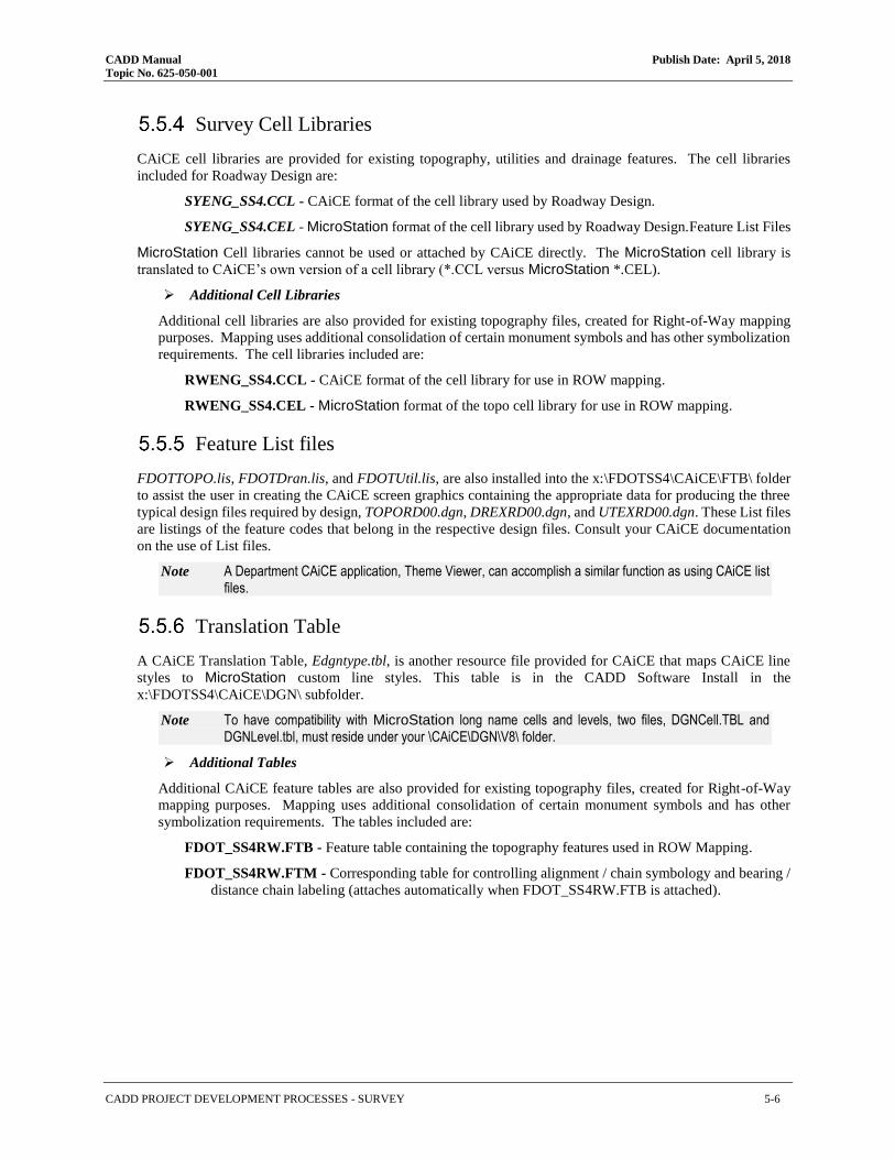
CADD Manual Publish Date: April 5, 2018
Topic No. 625-050-001
CADD PROJECT DEVELOPMENT PROCESSES - SURVEY 5-6
Survey Cell Libraries
CAiCE cell libraries are provided for existing topography, utilities and drainage features. The cell libraries
included for Roadway Design are:
SYENG_SS4.CCL - CAiCE format of the cell library used by Roadway Design.
SYENG_SS4.CEL - MicroStation format of the cell library used by Roadway Design.Feature List Files
MicroStation Cell libraries cannot be used or attached by CAiCE directly. The MicroStation cell library is
translated to CAiCE’s own version of a cell library (*.CCL versus MicroStation *.CEL).
➢ Additional Cell Libraries
Additional cell libraries are also provided for existing topography files, created for Right-of-Way mapping
purposes. Mapping uses additional consolidation of certain monument symbols and has other symbolization
requirements. The cell libraries included are:
RWENG_SS4.CCL - CAiCE format of the cell library for use in ROW mapping.
RWENG_SS4.CEL - MicroStation format of the topo cell library for use in ROW mapping.
Feature List files
FDOTTOPO.lis, FDOTDran.lis, and FDOTUtil.lis, are also installed into the x:\FDOTSS4\CAiCE\FTB\ folder
to assist the user in creating the CAiCE screen graphics containing the appropriate data for producing the three
typical design files required by design, TOPORD00.dgn, DREXRD00.dgn, and UTEXRD00.dgn. These List files
are listings of the feature codes that belong in the respective design files. Consult your CAiCE documentation
on the use of List files.
Note A Department CAiCE application, Theme Viewer, can accomplish a similar function as using CAiCE list files.
Translation Table
A CAiCE Translation Table, Edgntype.tbl, is another resource file provided for CAiCE that maps CAiCE line
styles to MicroStation custom line styles. This table is in the CADD Software Install in the
x:\FDOTSS4\CAiCE\DGN\ subfolder.
Note To have compatibility with MicroStation long name cells and levels, two files, DGNCell.TBL and DGNLevel.tbl, must reside under your \CAiCE\DGN\V8\ folder.
➢ Additional Tables
Additional CAiCE feature tables are also provided for existing topography files, created for Right-of-Way
mapping purposes. Mapping uses additional consolidation of certain monument symbols and has other
symbolization requirements. The tables included are:
FDOT_SS4RW.FTB - Feature table containing the topography features used in ROW Mapping.
FDOT_SS4RW.FTM - Corresponding table for controlling alignment / chain symbology and bearing /
distance chain labeling (attaches automatically when FDOT_SS4RW.FTB is attached).

CADD Manual Publish Date: April 5, 2018
Topic No. 625-050-001
CADD PROJECT DEVELOPMENT PROCESSES - SURVEY 5-7
➢ Special Characters
CAiCE does not support True Type Fonts. CAiCE Font(s) 48 & 58 must be replaced by True Type Fonts in
MicroStation if the CDG2V8 Macro is used for importing CAiCE data.
CAiCE font 48 and translating to MicroStation - Font 48 does not use the standard ASCII table for
all special characters. In particular, the degree symbol ( ° ) for MicroStation requires that CAiCE
place the Caret Symbol ( ^ ) in CAiCE text strings so MicroStation will look correct when data is
translated to MicroStation graphics. To force CAiCE to substitute the ( ^ ) for the degree ( ° ),
CAiCE needs to be set by selecting the menu options: Settings > Special Characters and set the
ASCII value of 94 to represent degrees as shown in the figure to the right.
Right of Way project font 58 in MicroStation - If exporting to a Right of Way map, CAiCE needs to
be set by selecting the menu items: Settings > Special Characters and set the ASCII value 33 to the
Delta symbol as shown in the figure to the right.
County Mapping
The production of County Maps is an internal function of the Department’s Surveying and Mapping Office. This
documentation refers to the graphical symbology standards used for the production of those maps. For
information regarding file naming conventions and other standards in use during the production of the
Department’s County maps, contact the Geographic Mapping Office in the Department’s Surveying and
Mapping Office at (850) 414-4111.
http://www.fdot.gov/geospatial/countymap.shtm

CADD Manual Publish Date: April 5, 2018
Topic No. 625-050-001
CADD PROJECT DEVELOPMENT PROCESSES - SURVEY 5-8
Utility Quality Levels
Chapter 556, F.S. incorporate locates as described in the 1999 Utility Accommodation Manual (UAM), Section
11.3 Locates. These are no longer described in the UAM.
The following identifies the level of utility locates in ascending order:
Level “D” -Existing Records
Level “C” -Surface Visible Feature Survey
Level “B” -Designating
Level “A” –Locating
Level “D” locates are information obtained solely from a review of utility records. The comprehensiveness and
accuracy of such information is highly limited. Even when existing information for a utility in a particular area
is accurate, there are often other underground systems that are not shown on any records. Level “D” may be
appropriate for use early in the development of a project to determine the presence of utilities.
Level “C” locates are information obtained to augment Level “D” information. This involves topographic
surveying of visible, above ground utility features such as poles, hydrants, valve boxes, circuit breakers, etc.
Level “C” may be appropriately used early in the development of a project and will provide better data than
Level “D” information alone. Designers can not be sure their design is appropriate nor can construction proceed
without caution when using information for underground utilities that is based only on Level “D” and “C”
locates.
Level “B” locates are information obtained through the use of designating technologies (e.g. geophysical
prospecting technologies). This is an application using scanning technologies, most of which have very specific
capabilities and limitations that vary with site conditions. Applying a variety of techniques is essential to the
process of preparing a comprehensive horizontal map of utilities and other underground structures on the site.
Designating technologies are capable of providing reasonable horizontal information but provide limited vertical
information.
Level “A” locates provide the highest level of accuracy of utility locations in three dimensions. This level may
apply manual, mechanical or nondestructive (e.g., vacuum excavation) methods to physically expose utilities for
measurement and data recording. Levels “B”, “C”, and “D” locates are incorporated in Level “A” locates. The
designer should obtain Level “A” locates at highway/utility conflict points where verified information is
necessary.

CADD Manual Publish Date: April 5, 2018
Topic No. 625-050-001
CADD PROJECT DEVELOPMENT PROCESSES - TYPICAL SECTIONS PACKAGE 5-9
5.6 GEOTECHNICAL
Geotechnical Plans are included in the Roadway Plan Set as Soil Survey, Soil Boring and Bridge Data Sheets.
Geotechnical information must also be delivered (CSV format) as shown in the examples below. The
Department has adopted the following standard file naming convention for CSV file imports for the Geotechnical
Utility in GEOPAK:
Borehole - Boreholetpk.brh - Borehole location data, seasonal high water & design high water data.
Material - Material.mtl - Strata Data and Core data.
Standard Penetration Test (SPT) boring information may be drawn using the Department’s Report a Core Boring
Tool.
➢ Example: Boreholetpk.brh
Format: borehole_name,alignment_name,station,offset,water_elev_type,water_elev_0,water_elev_0_date,water_elev_24,water_elev_24_date
Examples: Borehole-01,CLCON,78+00.00,15,0,3,8/9/2007,5,8/10/2007
Borehole-02,CLCON,80+00.00,3,0,2,8/20/2007,4,8/21/2007
Borehole-03,CLCON,83+00.00,3,0,3,8/23/2007,5,8/24/2007
Borehole-04,CLCON,85+00.00,4,0,2,8/24/2007,4,8/25/2007
➢ Example: Material.mtl
Format: borehole_name,material_name,doc_or_se,type_of_elev
Examples: Borehole-01,1,10,DOC Borehole-03,2,6,DOC
Borehole-02,1,5,DOC Borehole-04,1,2,DOC
Borehole-02,2,7,DOC Borehole-04,2,5,DOC
Borehole-02,3,9,DOC Borehole-04,3,7,DOC
Borehole-03,1,3,DOC Borehole-04,4,10,DOC
➢ Soil Survey
The plans must include the information about the soil classification on the soil survey sheet and by showing
the boring data soil boxes on the crosssection sheets.
➢ Soil Boring Data
The soil boring data must be provided to the Roadway designer in a format to facilitate the drawing of the
data on the crosssection sheets.
5.7 TRAFFIC DATA
(CURRENTLY UNDER DEVELOPMENT)
5.8 TYPICAL SECTIONS PACKAGE
(CURRENTLY UNDER DEVELOPMENT)

CADD Manual Publish Date: April 5, 2018
Topic No. 625-050-001
CADD PROJECT DEVELOPMENT PROCESSES - UTILITIES 5-10
5.9 DRAINAGE
CADD provides software resources for Drainage plans preparation using GEOPAK and Civil 3D. Some Districts
utilize other Drainage analysis and design applications, such as Automated Storm Sewer Analysis and Design
(ASAD). The Drainage databases produced by drainage design applications must be delivered with the project.
Listed below are files created by Roadway that are to be treated as Drainage files:
DRDTRD##.DGN - Drainage Detail Sheets
DREXRD##.DGN - Drainage Existing Structures
DRFLRD##.DGN - Flood Data Form
DRMPRD##.DGN - Drainage Map (if required in the FDM) included in the final submittal
DRPRRD##.DGN - Drainage Proposed Structures
DRXSRD##.DGN - Drainage Structure Cross Sections
SUMDRD##.DGN - Summary of Drainage Structures
5.10 TRAFFIC CONTROL PLAN
(CURRENTLY UNDER DEVELOPMENT)
5.11 PAVEMENT
(CURRENTLY UNDER DEVELOPMENT)
5.12 UTILITIES
(CURRENTLY UNDER DEVELOPMENT)
There are three Utility file coordination options available for the UAO to share files with the Department:
❖ Exchange of design files (DGN or DWG) – the preferred option
❖ Create American Standard Code for Information Interchange (ASCII) files
❖ Import of Geographic Information System (GIS) data
➢ Sharing of Design Files
Design files are created to the Department’s CADD Standards and returned to the District for review. The
UAO will use these files as references to create the existing or proposed utility files. These files (existing or
proposed) would also be submitted back to the District. It is the District’s responsibility to coordinate with
the UAO for delivery of design files. For AutoCAD DWG files, all line work for utilities should be
preferably in 3D and saved as polylines or feature line objects.
➢ ASCII Input File
The second option is the ASCII file that can be created from existing or proposed utilities. The ASCII file
format will be either LandXML or GEOPAK input format for Station/Offset/Elevation or
Northing/Easting/Elevation (State Plane coordinates). These files must contain information pertinent to the
location of the utility, as well as the type of utility and where it is located referenced to the (survey baseline)
alignment or state plane coordinates.

CADD Manual Publish Date: April 5, 2018
Topic No. 625-050-001
CADD PROJECT DEVELOPMENT PROCESSES - UTILITIES 5-11
➢ Geographic Information System (GIS) File
In the event that a UAO maintains a GIS database of utility data, that data may be exchanged in GIS shape
files.
➢ Utility Coordination

CADD Manual Publish Date: April 5, 2018
Topic No. 625-050-001
CADD PROJECT DEVELOPMENT PROCESSES - UTILITIES 5-12

CADD Manual Publish Date: April 5, 2018
Topic No. 625-050-001
CADD PROJECT DEVELOPMENT PROCESSES - UTILITIES 5-13
➢ Exchange of Design Files
After the Department’s District Utilities Office (via Utility Coordinator) has received the current phase
submittal from the Designer, they must contact the involved utilities and notify them of the phase submittal.
The UAO will then receive the phase documents from the Department that must contain the Roadway Plans,
the necessary CADD files and any Utility Relocation Agreements and Schedules. The required electronic
files include the proposed roadway design; the existing topography, the existing and proposed R/W and the
existing utilities gathered from the survey and previously supplied data.
No editing of any files provided by the Department will be accepted. The UAO will be placing data into
newly created files. File naming standards must be maintained at all times.
➢ Utility Work by Highway Contractor Agreement Plans
Major highway construction elements such as pavement areas, bridges, drainage structures, right of way, lane
widths, control of access limits and highway-straight-line numbers should appear in the Utility Work by
Highway Contractor Agreement Plans.
The Department’s plans marked by the UAO will use the following color code:
• Red: Existing utilities either (a) To be removed or relocated horizontally or (b) to be placed out-
of-service (deactivated) but left in place.
• Green: Existing utilities to remain in place with no adjustment.
• Brown: Either (a) Existing utilities to be adjusted vertically but to remain in the same horizontal
alignment, or (b) Completely new utilities to be installed.
One set of the plans should be returned to the Department with each copy of the Utility Agreement.
➢ ASCII Files of Utility Data
ASCII Files of utility data are to be exchanged in the LandXML format which is ubiquitous with most civil
design and GIS software. Information about LandXML can be found at: http://www.LandXML.org.
➢ The File Naming Convention for this ASCII files must be:
utilex##.xml for Existing Utilities
utilpr##.xml for Proposed Utilities
➢ Alternately, ASCII files of Utility Data File Naming Convention must be:
utilex##.inp for Existing Utilities. Note the inp extension for GEOPAK input
utilpr##.inp for Proposed Utilities. Note the inp extension for GEOPAK input
Where ## will be a sequencing number (01, 02, 03, etcetera).
Each electronic ASCII report file must be stored on media according to the Department’s CADD Deliverable
Standards. If the provider does not have capability to deliver in LandXML format, a GEOPAK Input format
file will also be an acceptable substitute. When delivery is made in GEOPAK Input format, the ASCII report
must be accompanied by a printed hardcopy.
➢ Utility Scanned Images
If the Utilities are handled through a Joint Utility Agreement and electronic files are not provided to the
District for the Utility plans, the paper plans must be scanned. The format must be a published format with a
minimum resolution of 300DPI. The required formats are PDF or Group 4 TIFF.

CADD Manual Publish Date: April 5, 2018
Topic No. 625-050-001
CADD PROJECT DEVELOPMENT PROCESSES - UTILITIES 5-14
[THIS PAGE INTENTIONALLY LEFT BLANK]
CADD Manual Publish Date: April 5, 2018
Topic No. 625-050-001
CADD STANDARDS - GENERAL 6-1
CADD STANDARDS
6.1 PURPOSE
This chapter defines the Florida Department of Transportation (Department’s) critical Computer Aided Design
& Drafting (CADD) Production Standards to be used in the production of the Department’s CADD projects.
6.2 SCOPE
These Production Standards apply to all projects produced by and for the Department using CADD in addition
to the Department’s custom criteria, standards and procedures of the various disciplines within the Department.
6.3 GENERAL
The Department develops CADD Standards through the Production Support CADD Office for production of
Florida transportation plans to be delivered with the aid of the CADD Software Suite. The Production Support
CADD Office manages and coordinates these CADD Standards through customizations within the Department’s
approved CADD software platforms and the tools contained in the CADD Software Suite.
The CADD Software Suite includes standard design libraries / templates to propagate the CADD Standards
definitions of levels / layers and symbology (color, line styles / linetypes, weights), multi-line styles, text styles,
dimension styles, cells, element templates, menu customizations, customized tools, tool boxes, and tasks for two
platforms: MicroStation and AutoCAD. The Department’s custom CADD resource definitions for CADD
drawings are consistent between the MicroStation and AutoCAD platforms. The following are examples of
platform conventions:
MicroStation AutoCAD
Database file Database file
Seed file Sheet Template
Design Library Design Template
Cell Library Block Drawing
Cell Name Block Name
Print Configuration Print Configuration
File Name File Name
Level Name Layer Name
Color Color
Line Style Linetype
Line Weight Line Weight
Projects will be maintained and updated with the latest available and CADD Software Currently Supported
versions published on the Production Support CADD Office. Exceptions must be approved by the Department's
Project Manager and must be documented and delivered as part of the Department’s project.

CADD Manual Publish Date: April 5, 2018
Topic No. 625-050-001
CADD STANDARDS - DATABASE (DDB) RESOURCES 6-2
6.4 3D MODELING STANDARDS
Corridor Frequency Interval Spacing for 3D Design
Design software used by the Department samples the 3D corridor models at user defined intervals in order to
create surfaces. To ensure reasonable fidelity in surface models for AMG operations, maximum sampling
intervals are described below:
Note The designer may choose to sample more frequently to more accurately represent his design model, although, there is a limiting return (larger files and poorer computer performance) if sampling too frequently. Designers must balance these competing consequences when deciding appropriate sampling frequency for their projects.
Facility Design Speed < 45
MPH Design Speed > 45 MPH
Rural Sections maximum corridor interval
Tangents 20 feet 20 feet
Curves 10 feet 10 feet
Intersections 5 feet 5 feet
Urban Sections maximum corridor interval
Tangents 10 feet 20 feet
Curves 5 feet 10 feet
Intersections 2 feet 5 feet
Additional sampling intervals will normally be needed at critical regions in horizontal geometry stations (i.e.
PC’s, PT’s), superelevation transition locations, and at profile geometry critical locations (i.e. PVC’s, PVT’s,
and profile high/low points). The designer must also add sampling at other critical regions along the corridor,
such as changes of typical section, critical drainage locations, approach and interior to intersections, and median
crossovers.
6.5 DATABASE (DDB) RESOURCES
MicroStation
For MicroStation projects the Department’s CADD Software Suite includes a GEOPAK Design and Computation (D&C) Manager database file, FDOTXXX.ddb, located in the \FDOTXXX\geopak\databases\
folder, where ‘XXX’ or ‘XXXX’ represent the versioning of the Department’s CADD Software Suite. This
database is set up specifically to create drawing elements and attach pay item data according to the Department’s
CADD Standards.
These resources may need to be modified for project specific items or to comply with District standards. If the
GEOPAK D&C Manager FDOTXXX.ddb database is customized, a copy of this project specific custom
database must be saved into the project folder in the \symb\ sub-folder to ensure the modified database will be
delivered with the project; likewise, a modified copy of the AutoCAD AECMerge.XML file must be saved to the
\symb\ project sub-folder.

CADD Manual Publish Date: April 5, 2018
Topic No. 625-050-001
CADD STANDARDS - SEED / SHEET TEMPLATE FILES 6-3
When modifying project specific database resource, the following naming convention must be used:
Project Financial Project Identification Number[Discipline Designation].ddb
Where Discipline Designation would be one of the following:
dr (drainage)
it (intelligent transportation system)
ld (landscape)
lt (lighting)
rd (roadway)
sg (signalization)
sp (signing and pavement markings)
ut (utilities)
Example: Modified Signalization DDB: 19728125201sg.ddb stored in \19728125201\symb\ subfolder.
AutoCAD
For Autodesk projects the Department’s CADD Software Suite includes an Entity Manager Pay Item Database file, EntityManagerPayitemDatabase.txt, located in the \FDOT20XX.C3D\APPS\EntityManager
folder, where ‘XX’ represents the versioning of the Department’s CADD Software Suite. This database is set
up specifically to create drawing entities and attach pay item data according to the Department’s CADD
Standards.
These resources may need to be modified for project specific items or to comply with District standards. If the
Payitemdb database is customized, a copy of this custom database must be saved into the project folder in the
\symb\ project sub-folder to ensure the modified database will be delivered with the project. When modifying
project specific database resources, the following naming convention must be used:
Project Financial Project Identification Number[Discipline Designation].xml
Where Discipline Designation would be one of the following:
dr (drainage)
it (intelligent transportation system)
ld (landscape)
lt (lighting)
rd (roadway)
sg (signalization)
sp (signing and pavement markings)
u (utilities)
Example: Modified Signalization XML: 19728125201sg.xml stored in \19728125201\symb\ project subfolder.
6.6 SEED / SHEET TEMPLATE FILES
MicroStation Seed Files
MicroStation uses “seed” files to create all design files. Working units and global origin are two of the most
important settings in the seed file. Working units are expressed as master units and sub-units. All standard seed
files for MicroStation have been defined based on a master unit of “Survey Feet” with a sub unit of “Survey
Inches.” The global origin is located at the center of the design plane for all seed files.
The resolution in MicroStation files is defined per the master unit and determines the size (working area) of the
design plane, which must encompass an area large enough for any State Plane coordinate zone in Florida. The
resolution is set to 304800 units of resolution (UORs) per Survey Foot.

CADD Manual Publish Date: April 5, 2018
Topic No. 625-050-001
CADD STANDARDS - SEED / SHEET TEMPLATE FILES 6-4
Set the geographic coordinate system to the appropriate Florida State Plane Zone in production drawings derived
from the seed files.
Discipline Seed Filename Description
Right of Way rwseed2d.dgn Right of Way Seed File
Roadway fdotseed2d.dgn Roadway 2D Seed File
Roadway fdotseed3d.dgn Roadway 3D Seed File
Roadway fdotseedkeymap.dgn Roadway Key Map Seed File
Roadway fdotseedxs.dgn Roadway Cross Section Seed File
Structures structuresseed.dgn Structures Seed File
Structures structuresseed3d.dgn Structures 3D Seed File
fdotmaster.dwt FDOT Master
AutoCAD Sheet Template Files
The FDOT Standard Sheet Borders used for plan production for all disciplines are listed below. The user
accesses these files when using any of the AutoCAD Create Sheets wizard. Upon selection of the appropriate
sheet template, a drawing scale is selected. Each Sheet Template file contains sheet layouts at designated scales
along with fields in the border that can be automatically updated with project information, such as Sheet Title,
Sheet Number, County, Etc. The Crosssection sheet templates update with the appropriate material volume when
sections sheets are created based on the material list selected in AutoCAD.
Discipline Template Filename Description
Right of Way CSCOVR.dwt Control Survey Cover Sheet
Right of Way CSDETL.dwt Control Survey Detail Sheet
Right of Way MMCOVR.dwt Maintenance Map Cover Sheet
Right of Way MMDETL.dwt Maintenance Map Detail Sheet
Right of Way RWCOVR.dwt Right of Way Cover Sheet
Right of Way RWDETL.dwt Right of Way Detail Sheet
Right of Way RWPS.dwt Right of Way Parcel Sketch Sheet
Right of Way RWSHT.dwt Right of Way Sheet
Right of Way RWSPS.dwt Right of Way Specific Purpose Survey Sheet
Right of Way RWTAB.dwt Right of Way Tabulation Sheet
Roadway CTLSRD.dwt Reference Points Horizontal Vertical Control Sheet Border
Roadway SHDrainMap.dwt FDOT Drainage Map Sheet Border
Roadway SHPLAN.dwt FDOT Sheet Border
Roadway SHPlanDual.dwt FDOT Dual Plan View Sheet Border
Roadway SHPlanDual-Top.dwt FDOT Dual Plan View Sheet Border
Roadway SHPlanProfOpt.dwt FDOT Plan Profile Optional Sheet Border
Roadway SHPlanProfOpt-Intersection.dwt FDOT Plan Profile Optional Intersection Sheet Border
Roadway SHPlanProfStd.dwt FDOT Plan Profile Standard Sheet Border
Roadway SHProfDual.dwt FDOT Dual Profile Sheet Border
Roadway SHProfDualOpt.dwt FDOT Dual Profile Optional Sheet Border
Roadway SHProfile.dwt FDOT Profile Sheet Border
Roadway SHProfOpt.dwt FDOT Profile Optional Sheet Border
Roadway SHXSC.dwt FDOT Cross Section 2' Grid Sheet Border
Roadway SHXSC1EW2.dwt FDOT Cross Section 2 Material Sheet Border
Roadway SHXSC1EW3.dwt FDOT Cross Section 3 Material Sheet Border
Roadway SHXSC1EW3-Overbuild.dwt FDOT Cross Section 2 Material with Overbuild Sheet Border
Roadway SHXSC2EW2.dwt FDOT Dual Vertical Cross Section 2 Material Sheet Border
Roadway SHXSG.dwt FDOT Cross Section 1' Grid Sheet Border
Roadway SHXSG1EW2.dwt FDOT Cross Section 1' Grid 2 Material Sheet Border
Roadway SHXSG1EW3.dwt FDOT Cross Section 1' Grid 3 Material Sheet Border
Roadway SHXSG2EW2.dwt FDOT Dual Vertical Cross Section 1' Grid 2 Material Sheet Border
Structures StructuresKeySheetTemplate.dwt Structures Key Sheet
Structures StructuresPlanProfile.dwt Structures Plan & Profile

CADD Manual Publish Date: April 5, 2018
Topic No. 625-050-001
CADD STANDARDS - STANDARD DESIGN LIBRARIES / TEMPLATES 6-5
6.7 STANDARD DESIGN LIBRARIES / TEMPLATES
CADD Standard Design Library (dgnlib) / Design Template (dwt) files have been customized containing data
that is shared throughout the Department’s standard files and amoung users. These shared resources consist of,
but not limited to, the Department’s standard Cells, Levels, Styles, and Features.
MicroStation Design Libraries
Type Design Library Name (DGNLIB) Description
Civil_Cells FDOT_Approach.dgnlib FDOT Approaches
Civil_Cells FDOT_BusTurnOut.dgnlib FDOT Bus Turn Outs
Civil_Cells FDOT_Circulatory.dgnlib FDOT Circulatory
Civil_Cells FDOT_CurbGutterMaker.dgnlib FDOT Curb & Gutter Maker
Civil_Cells FDOT_CurbTransitions.dgnlib FDOT Curb Transitions
Civil_Cells FDOT_DirectionalMedianOpenings.dgnlib FDOT Directional Median Openings
Civil_Cells FDOT_Driveways.dgnlib FDOT Driveways
Civil_Cells FDOT_FDM_Exhibits.dgnlib FDOT Design Manual Exhibits
Civil_Cells FDOT_Intersections.dgnlib FDOT Intersections
Civil_Cells FDOT_Ponds.dgnlib FDOT Ponds
Civil_Cells FDOT_RampTerminals.dgnlib FDOT Ramp Terminals
Civil_Cells FDOT_SidewalkCurbRamps.dgnlib FDOT Sidewalks, Curbs, & Ramps
Civil_Cells FDOT_Templates.dgnlib FDOT Templates
Features FDOT_CivilFeatures_RD.dgnlib FDOT Civil Features for Roadway
Features FDOT_CivilFeatures_RW.dgnlib FDOT Civil Features for Right of Way
Features FDOT_CivilFeatures_TC.dgnlib FDOT Civil Features for Traffic Control
Features FDOT_CivilFeatures_TP.dgnlib FDOT Civil Features for Traffic Plans
Features FDOT_CivilFeatures_UT.dgnlib FDOT Civil Features for Utilities
Features FDOT_ElementTemplates.dgnlib FDOT Element Templates
Features FDOT_SUE_Drainage.dgnlib FDOT Subsurface Utility Engineering for Drainage
Features FDOT_SUE_Utilities.dgnlib FDOT Subsurface Utility Engineering for Utilities
Features FDOT_SurveyFeatures_RD.dgnlib FDOT Survey Features for Roadway
Features FDOT_SurveyFeatures_RW.dgnlib FDOT Survey Features for Right of Way
General CivilCommands.dgnlib Civil Commands
General FDOT_DesignGeometricsCriteria.dgnlib FDOT Design Geometrics Criteria
General FDOTtoolboxes.dgnlib FDOTtoolboxes
General GeoTech.dgnlib Geotechnical
Levels countymappinglevels.dgnlib County Mapping Levels with Symbology
Levels fdot_common_levels.dgnlib FDOT Common Levels with Symbology
Levels fdot_v8_levels.dgnlib FDOT V8 Levels with Symbology
Levels Photogrammetry_levels.dgnlib Photogrammetry with Symbology
Levels rwlevels.dgnlib Right of Way Levels with Symbology
Levels strlevels.dgnlib Structurres Levels with Symbology
Levels survey_levels.dgnlib Survey Levels with Symbology
Levels v7_levels.dgnlib v7 Levels with Symbology
Styles FDOT_PrintStyles.dgnlib FDOT Print Styles
Styles FDOT_Styles.dgnlib FDOT Styles
Styles rwstyles.dgnlib Right of Way Styles

CADD Manual Publish Date: April 5, 2018
Topic No. 625-050-001
CADD STANDARDS - CELL LIBRARIES / BLOCK DRAWINGS 6-6
AutoCAD Design Template Files
AutoCAD also uses “template” files to create design files. Drawing units are also US Survey Feet and the
geographic coordinate system for production drawings derived from templates must be set for the project’s State
Plane Zone. Templates are style based AutoCAD drawings.
Template Description
fdotmaster.dwt Master Template
keysht.dwt Key Sheets
planrd.dwt Sheet Border for Details, Typical Sections & Summary Boxes
rwdtrd.dwt Right of Way Detail for Roadway
rweng10.dwt Right of Way
spst10.dwt Structures
StructuresTemplateDetail.dwt Structural Details
StructuresTemplatePlan.dwt Structural Plans
survey.dwt Survey Development Model
toporw.dwt Existing Topography for Right of Way
TypSectionPkg.dwt Typical Section Package
utadrd.dwt Utilities Adjustment
utprrd.dwt Utilities Proposed
6.8 CELL LIBRARIES / BLOCK DRAWINGS
Cells / Blocks are frequently used as repeated components of drawings made up of complex symbols, notations,
details, or parts of drawings that can be inserted into one or many other drawings. Cells are defined and stored
in MicroStation design files called a Cell Libraries with a .cel file extension and in AutoCAD are called Blocks
Drawings.
Cells / Blocks have been grouped by disciplinary usage into the Department’s Standard Cell Libraries / Block
Drawings and are delivered with the CADD Software Suite. MicroStation Cell Libraries are delivered under the
FDOTXXX\RESOURCES\Cell\ subfolder. AutoCAD Block Drawings delivered in the FDOT State Kit under
the FDOTXXXX.C3D\Data\Blocks\ subfolder.
➢ Standard Cell Libraries / Block Drawings
Note Select links to open complete cell listings for each Cell Library.
MicroStation
CELL LIBRARIES
AutoCAD
BLOCK DRAWINGS DESCRIPTION
FDOT Cell Libraries - Master Master listing of all FDOT Cells
alphabet.cel Alphabet & Numbers
arrows.cel arrows.dwg Distance & GuidSIGN Arrows
Drain_Bottom3D.cel (AutoCAD Drainage Parts) Drainage Bottom (3 Dimensional used for SUDA)
Drain_Curbs3D.cel (AutoCAD Drainage Parts) Drainage Curbs (3 Dimensional used for SUDA)
Drain_Grate3D.cel (AutoCAD Drainage Parts) Drainage Grate (3 Dimensional used for SUDA)
Drain_Junction3D.cel (AutoCAD Drainage Parts) Drainage Junction (3 Dimensional used for SUDA)
Drain_Nodes3D_EX.cel (AutoCAD Drainage Parts) Drainage Nodes (3 Dimensional used for SUDA)
Drain_Outlet3D.cel (AutoCAD Drainage Parts) Drainage Outlet (3 Dimensional used for SUDA)
DrainXS.cel DrainXS.dwg Drainage Structure Cross Sections
drplan.cel drplan.dwg Drainage Proposed
drplan_ex.cel drplan_ex.dwg Drainage Existing
ftpsigns.cel ftpsigns.dwg Florida Traffic Plans Signs
geotech.cel geotech.dwg Geotechnical
its.cel its.dwg Intelligent Transportation Systems Signs
Landscape.cel landscape.dwg Landscape
Lighting.cel lighting.dwg Lighting
Mutcd.cel mutcd.dwg Manual on Uniform Traffic Control Devices
PavementMarkings.cel pavementmarkings.dwg Pavement Markings

CADD Manual Publish Date: April 5, 2018
Topic No. 625-050-001
CADD STANDARDS - CELL LIBRARIES / BLOCK DRAWINGS 6-7
MicroStation
CELL LIBRARIES
AutoCAD
BLOCK DRAWINGS DESCRIPTION
Photogrammetry.cel Photo.dwg Photogrammetry
Roadway.cel Roadway.dwg Roadway
row.cel ROW.dwg Right of Way
rweng.cel rweng.dwg Survey Symbols for Right of Way
Seals.cel Seals.dwg Professional Seals for Digital Signatories
Signalization.cel signalization.dwg Signalization
SignalPoles.cel signalpoles.dwg Signal Poles
syeng.cel syeng.dwg Survey Symbols for Roadway
TollPlaza.cel TollPlaza.dwg Toll Plaza Signs
tplabels.cel tplabels.dwg Traffic Plans Labels
TrafficControlPlans.cel TrafficControlPlans.dwg Traffic Control Plans
TrafficControlTypicals.cel TrafficControlTypicals.dwg Traffic Control Typicals
transit.cel Bus Lane Stops and Crossings
TTF_StdDataTables.cel TTF_StdDataTables.dwg Structures Standard Data Tables
TTF_v8structures.cel TTF_v8Structures.dwg Structures
TypicalSection.cel TypicalSections. dwg Typical Sections
utilities.cel utilities.dwg Utilities
Utilities3D.cel (AutoCAD Parts) Utilities (3 Dimensional)
v8structurespatterns.cel Patterns for Structures
XMSuperSection.cel Structures for Super sections
xsections.cel Cross Sections
➢ Standard Dynamic Cell Libraries / Block Drawings
(Select links to open complete listings within each Cell Library.)
MicroStation
DYNAMIC CELL LIBRARIES AutoCAD
DYNAMIC BLOCKS DESCRIPTION
BoreHOLE.dwg Bore Holes
Master Table Drawing.dwg Master of All Summary Tables
Sheet Border.dwg Sheet Borders
SheetPOR-Consultant.dwg Professional of Record for Consultants
➢ Standard Civil Cell Libraries / Block Drawings
(Select links to open complete listings within each Cell Library.)
MicroStation
CIVIL CELL LIBRARIES AutoCAD
CIVIL BLOCKS DESCRIPTION
Bus Bay with Type F Curb.dwg Bus Bay with Type F Curb
CurbGutter.dwg Curb & Gutter
Driveway.dwg Driveway
Mast Arm Assemblies.dwg Mast Arm Assemblies
Tapered TurnLane with Type F Curb.dwg Tapered TurnLane with Type F Curb
Traffic Separator with Tapered Median.dwg Traffic Separator with Tapered Median

CADD Manual Publish Date: April 5, 2018
Topic No. 625-050-001
CADD STANDARDS - STANDARD FILE NAMES 6-8
6.9 STANDARD FILE NAMES
The Departmtent has defined a standard file naming convention for the design files for use in the Department’s
CADD projects wih specific standard file name lists for each discipline. These Standard filenames are stored
within the specified discipline folder of the Department’s project folder structure. Detailed listings are provided
later in this document.
In the event a non-standard file name is required for the project, either the Project Manager or the District CADD
Manager will be consulted to determine and approve of a proper filename to utilize.
The Department also identifies these standard design files as either “critical” or “non-critical.” Critical files are
frequently used in downstream applications, shared across disciplines, and used in quantifying pay items. These
“critical” files must meet a minimum compliancy for CADD symbology.
Standard Design File Naming Convention
The Department utilizes standard naming conventions for design files and provides applications that depend on
these naming conventions being met. The naming convention also confers information to downstream users
about the data contained within the design file. The Department delivers a CreateFiles application to assist in
producing Design files with the standard naming convention.
➢ Standard design filename format: AAAABB##.ext
AAAA = Abbreviated File Description, specific for each Discipline.
BB = Discipline Designation,
## = A file Sequence Number (a padded integer, i.e. “00”, “01”, “02” … “99”,
used to sequence additional files of the same Description + Denotation),
.ext = File extension indicating the type of file.
For Example: The first proposed Roadway cross section file would be named: rdxsrd01.dgn
The first six (6) characters of the standard design file naming convention described above are also critical
triggers for QC software and symbology filters. If it is necessary to add additional identifying information
in the design filename, this descriptive information should be inserted after the discipline denotation “BB”
and preceding the sequence number “##”.
For Example: rdxsrd-rampA-01.dgn, might indicate this proposed cross section file includes Ramp A.
➢ Special Characters
Letters (A-Z, a-z), numbers (0-9), dashes (-), and underscores (_) characters are the only legal characters in
file names. Characters and spaces that interfere with operating system path specifications or XML
interpretation such as: (/ \ . : ;, < & # >”) must be avoided.
➢ Large Projects
Very large projects might also necessitate the need to exceed two-digit sequence numbers (100+); otherwise
the sequence should be limited to two digits.
➢ Duplicate Files
There must not be duplicate CADD (DGN, DWG, etcetera) design file names within a project folder
structure. This is necessary to ensure proper reference attachments in CADD files. The FileChecker
application can be used to help find duplicate filenames within the project folder structure.
Note MicroStation and AutoCAD, as part of their search sequence, will use the first occurrence of a file name found as they traverse a folder structure looking for reference attachments with no paths.
Duplicate file names for source attachments can “corrupt” data references. Always use the “relative path” option, but never “full” or “no path” when attaching references.

CADD Manual Publish Date: April 5, 2018
Topic No. 625-050-001
CADD STANDARDS - STANDARD FILE NAMES 6-9
6.9.1.1 Structures Standard Design File Naming Convention
The Department identifies structural project design files with additional File Naming attributes to address
and document specific bridge information.
➢ Standard file names for Bridges format: B#AAAA…##.[ext]
Where: B# = Bridge Plans Sequence Number, AAAA… = Abbreviated File Description, ## = Sequence Number.
For Example: First EndBent sheet of Bridge 1 in a plan set would be named B1EndBent01.dgn
Files created by Structures remain in the \struct\ discipline folder, the sheet numbers must be prefixed with
the target discipline’s sheet prefixes.
The Department delivers the Create File/Project applications within the CADD Software Suite to ensure
files are named to Department CADD Standards.
Files containing Data Table cells (previously semi-standards) should be named B#DataTable##.dgn and
should be placed in the plans with the corresponding component detail sheet. Files marked as Geotech are
listed to show the order of placement within the Structures plans component only. All Geotech files should
be located in the \Geotech\ discipline folder and should follow Geotechnical Standards listed in this
document.
The table below defines the Department’s Structures standard file names; each must include sequence
numbering. Sheet Order is the default, but is modifiable to suit project specific requirements.
Note See Section 6.7.2 of this document for more information about Standard File Names. See Appendix A for the complete listing of level/symbology standards for each applicable CADD Standard Rule. See Structures Detailing Manual Volume 2, Chapter 3 for complete details on sheet numbering instructions.
Sheet Order reflects placement within the Structures Component of the Contract Plan Set.
➢ Non-Bridge Related Filenames:
Create the following non-bridge related files in the Structures workspace using Structures seed files. Include
mast arm and overhead sign structure sheets in the Roadway plans. Include the sheets for all other listed items
in the Roadway plans when no Structures plans are present.
➢ Resource Files
Files created for the Structures discipline must use the resource files included with the Department’s CADD
Software packages. All files created for Structures Plans sheets must be created from the supplied Structures
Seed or Template files. The Structures Seed/Template files for the FDOT Structures Workspace differs from
other Seed files in both working units and unit labeling.
The StrLevels.dgnlib library file contains the definitions for Levels, Text, & Dimension styles in
MicroStation.
The StructuresTemplateDetail.dwt and StructuresTemplatePlan.dwt template files contain the definitions
Levels, Text, & Dimension Styles in AutoCAD.
For V8 format MicroStation files, working units DO NOT define design plane size, only the method of
measurement. Therefore, the design plane is the same size for all seed files.

CADD Manual Publish Date: April 5, 2018
Topic No. 625-050-001
CADD STANDARDS - STANDARD FILE NAMES 6-10
6.9.1.2 Architectural Standard Design File Naming Convention
AutoCAD files are 3D for large plans, elevations or sections that contain the physical building components
(walls, doors, water piping, beams…). These files are drawn in Model Space at full scale. These files are
referenced in whole or part into sheet files where text and dimensions are added, then printed.
➢ Architectual Naming Components:
• Architectural Projects Identifier
• Discipline Codes
• Drawing Type Codes (General and Discipline related)
• File Sequence Number
Note Architectural Projects Identifier: A _-_ _ _.dwg Add “A” before Discipline Code as published in National CAD Standards. This distinguishes Building drawings from Roadway and Structures Plans.
Examples: Project Identifiers, Codes and File Sequence Numbers. For more detailed information refer to
National CAD Standards.
➢ Architectural Project Identifier
A _-_ _ _.dwg Architectural, this differentiates architectural building projects from bridges and
roadway projects.
➢ Discipline Code
_A-_ _ _.dwg .............................................................................................................. Architectural
_C-_ _ _.dwg ............................................................................................................................ Civil
_Z-_ _ _.dwg ......................................................................................... Contractor/Shop Drawings
_Q-_ _ _.dwg .................................................................................................................. Equipment
_ E-_ _ _.dwg ..................................................................................................................... Electrical
_A-_ _ _.dwg .............................................................................................................. Architectural
_C-_ _ _.dwg ............................................................................................................................ Civil
_Z-_ _ _.dwg ......................................................................................... Contractor/Shop Drawings
_Q-_ _ _.dwg .................................................................................................................. Equipment
_ M-_ _ _.dwg ................................................................................................................Mechanical
_ X-_ _ _.dwg ...................................................................................................... Other Disciplines
_ P-_ _ _.dwg .................................................................................................................... Plumbing
_ D-_ _ _.dwg ...................................................................................................................... Process
_ R-_ _ _.dwg ................................................................................................................... Resources
_ S-_ _ _.dwg ................................................................................................................... Structural
_ T-_ _ _.dwg .................................................................................................. Telecommunications

CADD Manual Publish Date: April 5, 2018
Topic No. 625-050-001
CADD STANDARDS - STANDARD FILE NAMES 6-11
➢ Drawing Type Code (general and discipline related)
_ _-FP _.dwg .................................................................................................................... Floor Plan
_ _-SP _.dwg ....................................................................................................................... Site Plan
_ _-DP _.dwg ........................................................................................................... Dimension Plan
_ _ -XP _.dwg .............................................................................................................. Existing Plan
_ _-EL _.dwg ..................................................................................................................... Elevation
_ _-SC _.dwg ........................................................................................................................ Section
_ _-DT _.dwg .......................................................................................................................... Detail
_ _-CP _.dwg ................................................................................................................ Ceiling Plan
_ _-EP _.dwg ............................................................................................................... Enlarged Plan
_ _-NP _.dwg .................................................................................................................. Finish Plan
_ _-RP _.dwg ............................................................................................................. Furniture Plan
_ _-SH _.dwg .................................................................................................................... Schedules
_ _-3D _.dwg ............................................................................................................... Isometric/3D
_ _-DG _.dwg ..................................................................................................................... Diagrams
➢ File Sequence Number
_ _-_ _ 1.dwg ...................................................................................... 1st drawing file in sequence
_ _-_ _ 2.dwg .................................................................................... 2nd drawing file in sequence
_ _-_ _ 3.dwg ..................................................................................... 3rd drawing file in sequence
6.9.1.3 Architectural Standard Sheet Naming Convention
A sheet file is a border sheet with dimensions and/or text added to a portion of a referenced model space file.
Plotted sheet files make up the plans set.
➢ Naming Components
• Architectural Projects Identifier
• Discipline Code
• Sheet Type Code
• Sheet Sequence Number
Examples: Project Identifiers, Codes and Sheet File Sequence Numbers. For more detailed information refer
to National CAD Standards.
➢ Architectural Project Identifier
A _-_ _ _.dwg .. Architectural, this differentiates Architectural building projects from bridges
and Roadway projects.

CADD Manual Publish Date: April 5, 2018
Topic No. 625-050-001
CADD STANDARDS - STANDARD FILE NAMES 6-12
➢ Discipline Code
_A-_ _ _.dwg .............................................................................................................. Architectural
_C-_ _ _.dwg ............................................................................................................................ Civil
_Z-_ _ _.dwg ......................................................................................... Contractor/Shop Drawings
_Q-_ _ _.dwg .................................................................................................................. Equipment
_ E-_ _ _.dwg ..................................................................................................................... Electrical
_ F-_ _ _.dwg ........................................................................................................... Fire Protection
_ G-_ _ _.dwg ..................................................................................................................... General
_ B-_ _ _.dwg .............................................................................................................. Geotechnical
_ H-_ _ _.dwg ................................................................................................. Hazardous Materials
_ I-_ _ _.dwg ....................................................................................................................... Interiors
_ M-_ _ _.dwg ................................................................................................................Mechanical
_ X-_ _ _.dwg ...................................................................................................... Other Disciplines
_ P-_ _ _.dwg .................................................................................................................... Plumbing
_ D-_ _ _.dwg ...................................................................................................................... Process
_ R-_ _ _.dwg ................................................................................................................... Resources
_ S-_ _ _.dwg ................................................................................................................... Structural
_ T-_ _ _.dwg .................................................................................................. Telecommunications
➢ Drawing Type Code (general and discipline related)
_ _-0 _ _.dwg ................................................................................... General (symbols, legend, notes…)
_ _-1 _ _.dwg .......................................................................................................................... Floor Plan
_ _-2 _ _.dwg ............................................................................................................................ Elevation
_ _-3 _ _.dwg .............................................................................................................................. Sections
_ _-4 _ _.dwg ........................................................................................................................ Large Scale
_ _-5 _ _.dwg ................................................................................................................................ Details
_ _-6 _ _.dwg .................................................................................................... Schedules and Diagrams
_ _-7 _ _.dwg ...................................................................................................................... User Defined
_ _-8 _ _.dwg ...................................................................................................................... User Defined
_ _-9 _ _.dwg .............................................................................. 3D Views (isometrics, perspectives…)
➢ File Sequence Number
_ _-_ 01.dwg ......................................................................................................... 1st sheet in sequence
_ _-_ 02.dwg ....................................................................................................... 2nd sheet in sequence
_ _-_ 03.dwg ........................................................................................................ 3rd sheet in sequence
➢ Detail File Name Format
The Detail File Name includes the sheet identifier and the
detail identification number. Sheet Identifier is the sheet
file that the detail is placed in. The detail identification
number represents the location of the detail within the
sheet file border.
➢ Schedule File Name Format
The Schedule File Name includes the sheet identifier
and the schedule identification number. Sheet Identifier
is the sheet file that the detail is placed in. The detail
identification number represents the location of the
schedule within the sheet file border.

CADD Manual Publish Date: April 5, 2018
Topic No. 625-050-001
CADD STANDARDS - STANDARD FILE NAMES 6-13
Standard Design Filename Tables
The Department has defined a list of Standard Design File Names within each discipline. Standard model names
are also provided. Shared files between two discipline groups must have the creation and ownership of these files
coordinated between these groups.
The file types listed in the following tables may be used by other disciplines, and the first four characters of the
file name are consistent between disciplines, but the fifth and sixth characters vary to reflect the discipline name.
Standard Model names are also provided in the table; however, it is not mandatory to use more than the default
model of those listed in this tables.
Select the links below to open an excel spreadsheet of the complete listing of applicable Standard File Names:
File Names by Component
01 Roadway File Names
02 Signing & Pavement Marking File Names
03 Signalization File Names
04 Intelligent Transportation Systems (ITS) File Names
05 Lighting File Names
06 Landscape File Names
07 Architectural (See section 6.9.1.2 and 6.9.1.3 of this document.)
08 Structures File Names
09 Toll Facilities (See section 7.6.9 of this document.)
10 Utilities File Names
Construction File Names
Drainage File Names
Environmental Management (EMO) File Names
Geotechnical File Names
Right of Way (ROW) File Names
Survey File Names
Typical File Name Extensions
Extension File Description Saved-in Folder
.3pc 3 Port Criteria Files Most appropriate discipline folder
.pdf Files for the PLANS Root project folder for fpid-PLANS.pdf for Digital Delivery.
.pdf Files for the SPECS \specs\ sub-folder for fpid-SPECS.pdf
.dxf AutoCAD ASCII Drawing Interchange File Most appropriate discipline folder
.dwg AutoCAD Design Files Most appropriate discipline folder
.dst AutoCAD Drawing Sheet Set \eng_data\ sub-folder for the discipline
.dwt AutoCAD Drawing Template \seed\ sub-folder of the project
.lin AutoCAD Linetype \symb\ sub-folder of the project
.pc3 AutoCAD Printer Configuration Most appropriate discipline folder or \symb\ sub-folder of the project
.shx AutoCAD Shape Compiled \symb\ sub-folder of the project
.shp AutoCAD Shape Files are ASCII Files \symb\ sub-folder of the project
.stb AutoCAD Plot Style Tables Most appropriate discipline folder or \symb\ sub-folder of the project
.csv Comma Separated Values Most appropriate discipline folder
.gpk Coordinate Geometry Database Files Most appropriate discipline folder
.alg Corridor Modeling Alignment Database Most appropriate discipline folder
.xlp Corridor Modeling Cross Section Labeling Preference File Most appropriate discipline folder
.xin Corridor Modeling Drafting Standards Most appropriate discipline folder

CADD Manual Publish Date: April 5, 2018
Topic No. 625-050-001
CADD STANDARDS - STANDARD FILE NAMES 6-14
Extension File Description Saved-in Folder
.rdp Corridor Modeling Roadway Design Preference File Most appropriate discipline folder
.ird Corridor Modeling Roadway Designer Database Most appropriate discipline folder
.dtm Corridor Modeling Surface Database Most appropriate discipline folder
.itl Corridor Modeling Template Library Most appropriate discipline folder
.hmr Descartes Raster Image Files Most appropriate discipline folder
.gpk GEOPAK COGO Database Most appropriate discipline folder
.x GEOPAK Criteria Files Most appropriate discipline folder
.ddb GEOPAK D&C Manager Database Files Most appropriate discipline folder
.gdf GEOPAK Drainage File Most appropriate discipline folder
.dlb GEOPAK Drainage Library Most appropriate discipline folder
.inp GEOPAK Input Files Most appropriate discipline folder
.prj GEOPAK Project Manager Project File Most appropriate discipline folder
.tin GEOPAK Surface Database Most appropriate discipline folder
.gif Graphics Interchange Format Most appropriate discipline folder
.jpeg,/.jpg Joint Photographic Experts Group Most appropriate discipline folder
.log Log File Most appropriate discipline folder
.xls(x) Microsoft Excel Spreadsheets Most appropriate discipline folder
.doc(x) Microsoft Word Documents Most appropriate discipline folder
.rsc MicroStation & GEOPAK Resource Files \eng_data\ sub-folder for discipline
.cel MicroStation Cell Libraries \cell\ sub-folder of the project folder
.dgn MicroStation Design Files Most appropriate discipline folder
.tbl MicroStation Pen Tables \eng_data\ sub-folder for discipline
.plt MicroStation Print Drivers \eng_data\ sub-folder for discipline
.pset MicroStation Print Organizer Print Set Most appropriate discipline folder
.pcf MicroStation Project Configuration Project Root folder
.dgnlib MicroStation Standards Database \symb\ if copied to local project
.sid Multi-resolution Seamless Image Database Most appropriate discipline folder
.ps Postscript Sheet Image Files \eng_data\ sub-folder for discipline
.xcp QC Exception Files \eng_data\ sub-folder for discipline
.txt QC Reports, QC ”Folder Name” \eng_data\ sub-folder for discipline
.tif Tagged Image File Most appropriate discipline folder
.htm/.html Web Pages Project Root folder and \data\ sub-folder
.xml XML Files Most appropriate discipline folder

CADD Manual Publish Date: April 5, 2018
Topic No. 625-050-001
CADD STANDARDS - STANDARD CADD RULES 6-15
6.10 STANDARD CADD RULES
The Department provides Standard Rules defining a prescribed group of levels / symbology to be validated for
each Standard Design File by the Quality Control (QC) process. Specific CADD standard “rules” are
automatically associated with each of the Department’s CADD standard design file names within the CADD
applications. These rules are defined related to a given discipline, or purpose for the file. These CADD standard
rules facilitate the QC software to check each of the standard design files for compliancy to the specification
found in these rules.
➢ Standard CADD Rules & Descriptions
Standard Rule Description
algnrd Alignment Design autosp AutoTURN cliprd Clip Border drdtrd Drainage Detail drexrd Drainage Existing drmprd Drainage Map drprrd Drainage Proposed drxsrd Drainage Cross Section dsgnld Landscaping Design dsgnlt Lighting Design dsgnrd Roadway Design dsgnsg Signalization Design dsgnsp Signing & Pavement Marking Design dtmrd Digital Terrain (Proposed)
gdtmrd Digital Terrain (Existing) geotech Geotechnical gisalgn Geographical Information System Alignment gispar Geographical Information System Parcels
gisrwdt Geographical Information System Right of Way Lines gswksp GuidSIGN irrgld Irrigation itssp Intelligent Transportation System
keysht Key Sheets msarsp Mast Arm Details open All Levels and Symbology Accepted
pdxsrd Pond Cross Section planrd Roadway Plan Sheet plprrd Roadway Plan / Profile Sheet qtdsrd Quantity Computation rdxsrd Roadway Cross Section rdxssp Signing & Pavement Cross Section rwdtrd Right of Way Detail for Roadway
rweng10 Right of Way spst10 Structural survrd Survey Development Model tcdsrd Traffic Control topord Existing Topography for Roadway typdrd Typical Section Data utadrd Utilities Adjustment utexrd Utilities Existing utprrd Utilities Proposed

CADD Manual Publish Date: April 5, 2018
Topic No. 625-050-001
CADD STANDARDS - STANDARD CADD LEVELS / LAYERS 6-16
CADD Standard Rule Tables
CADD Standard Rule Tables - Appendix A has comprehensive listings of the Department’s CADD Sandard
Rules with the associated CADD Standard Levels and Symbology.
The Appendix A can be downloaded from the link below:
FDOT CADD Standard Rule Tables - Appendix A
Exceptions to the Standard Rules
Exceptions are a deviation from those Standard Rules for any given project folder. For example, if a municipality
required a special symbology for an element not covered in a Standard Rule, that element could be drawn with
the special symbology and all occurrences of that symbology would be counted as one exception. The
Department allows up to 10 exceptions per standard design file before the compliance threshold begins to
diminish.
6.11 STANDARD CADD LEVELS / LAYERS
The Department’s CADD Software Suite includes standard design libraries / templates to propagate the CADD
standards definitions of (MicroStation) Levels / (AutoCAD) Layers and symbology (color, line styles / linetypes,
weights). The MicroStation Libraries are delivered under the \FDOTXXX\RESOURCES\dgnlibs\ folder and
the AutoCAD templates are delivered under the FDOTXXXX.C3D\Data\Templates\ folder.
The Department’s Level / Layer standards for projects define specific “ByLevel” Color, Style / Linetype and
Weight Symbology for graphic elements for both the Bentley and Autodesk platforms. In nearly every instance,
the names for Level / Layer, Color, Line Style / Linetype, etc. are the same between the platforms for consistency.
The Department’s CADD Software Suite also includes a Microsoft Excel MasterStandards.xlsx file documenting
these CADD Standards which is also used by the productivity tools for both MicroStation and AutoCAD
platforms, such as QCInspector (QC checking of design files during the Department’s plans preparation process).
Levels / Layers Naming & Designation Convention
The Department’s standard design libraries / templates define standard (MicroStation) Level / (AutoCAD) Layer
names. Designers must use these standard Levels / Layers in the Department’s plans production of all CADD
standard design files. The following describes the Department’s basic Level / Layer naming convention:
The format of the Level / Layer Name convention is: object_sv (maximum of 18 characters)
Where: (object) = Element Type
Note Level / Layer names with no “_sv” suffix are assumed to be “_pp” (Proposed state & Plan view).
Example: With this one can determine the following about the example Level / Layer names below: gas - Proposed state & Plan view elements for “gas” related items
gas_ep - Existing state & Plan view elements for “gas” related items
gas_px - Proposed state & Cross Section view elements for “gas” related items
(s) = State Designations (v) = View Designations
p (Proposed) p (Plan)
d (Drafting element) r (Profile)
e (Existing) x (Cross Section)
m (Model)

CADD Manual Publish Date: April 5, 2018
Topic No. 625-050-001
CADD STANDARDS - STANDARD CADD LEVELS / LAYERS 6-17
The Department’s CADD standard Levels / Layers are also classified as either Critical or Non-Critical for
purposes of the QC processes to verify compliancy of design files.
Non-Critical Levels / Layers are only checked in the QC process for compliancy with valid standard Level /
Layer names only.
Critical Levels / Layers are relied upon and used by downstream applications (or other disciplines) and are
checked in the QC process for compliancy with both valid standard level names along with “ByLevel” /
“ByLayer” settings for symbology (Color, Line Style, and Weight).
The CADD standard rules, documented in the MasterStandards.xlsx resource file and in Appendix A, contain a
Critical Level column that defines each level with the following designations:
[blank] Denotes Non-Critical Levels where ONLY valid Standard Level
Name is checked in the QC process.
X Denotes Critical Levels where valid Standard Level Name and
ByLevel setting for Symbology (color, line style, and weight) are
checked in the QC process.
3 Digit String Denotes Critical Level with partial checking in the QC process on
whether to check (1= true) or not to check (0=false) specific
symbology components: (Color, Line Style, Weight)
(1st digit = Color, 2nd digit = Line Style, 3rd digit = Weight)
Example:
100 – Denotes to check only color (common for structures files)
010 – Denotes to check only line style
101 – Denotes check both color & weight, but not line style
6.11.1.1 Structures Standard Level / Layer and Symbology
For the MicroStation FDOT Structures Workspace, element Level/Symbology Standards are defined in the
StrLevels.dgnlib Structures Level Library and must be selected from the MicroStation level picker. Each
level contains a defined color, line weight, line style, and print property. Color must remain set to BYLEVEL
(except where indicated with ** in the table below), line weight & line style may be modified as needed.
For AutoCAD, FDOT Structures object Layer Property Standards are defined in the
StructuresTemplateDetail.dwt and StructuresTemplatePlan.dwt template files and must be selected from the
AutoCAD layer selector. Each layer contains a defined color, line weight, linetype, and print property. Color
must remain set to ByLayer (except where indicated with ** in the table below), line weight & line style
may be modified as needed. User created Levels ARE NOT acceptable. If additional Levels/Layers are
needed, contact the Structures Design Office. The Level named “Default” (in MicroStation) or Layer 0 (in
AutoCAD) is not QC compliant and is not to be used for drawing elements. If a discrepancy occurs, the
StrLevels.dgnlib Structures Level Library or StructuresTemplate file supersedes the symbology table on the
following pages.

CADD Manual Publish Date: April 5, 2018
Topic No. 625-050-001
CADD STANDARDS - STANDARD CADD LEVELS / LAYERS 6-18
6.11.1.2 Architectural Level/Layers and Symbology
Refer to the National CADD Standards and Layer Symbology produced by the U.S. CADD/GIS Technology
Center, US Army Engineer Research and Development Center for Symbology standards. These standards
include space file names, sheet file names, detail file names, schedule file names, abbreviations, symbols,
layers, linetypes, and text styles.
All drawings must be drawn at Full Scale 1:1 in Modelspace using Architectural Units. Text and dimensions
should be added in Modelspace. The Titleblock Sheet should be in Paperspace and viewport scaled for
scalable printing.
All layer names must follow the format detailed in the National CAD Standards. Below is a brief description
of the layer naming convention.
➢ Examples: Codes, Groups and Fields
• Discipline Code • 1st Optional Minor Group A- - - Architectural - -FULL- Full height
E- - - Electrical - -DIMS- Dimension
F- - - Fire Protection ETC. M- - - Mechanical • 2nd Optional Minor Group ETC. - - -IDEN- Identification
• Major Group - - -PATT- Pattern
-WALL- - Walls ETC. -DOOR- - Doors • Status Field -LITE- - Lighting fixtures - - -N New work
-COLS- - Columns - - -D Demolition
ETC. - - -T Temporary work - - -F Future work ETC.
Discipline Code
Major Group
1st Optional Minor Group
Status Field
2nd Optional Minor Group
A-WALL-FULL-DEMO-E

CADD Manual Publish Date: April 5, 2018
Topic No. 625-050-001
CADD STANDARDS - STANDARD CADD SYMBOLOGY 6-19
6.11.1.3 Survey Level / Layer and Symbology Standards
Refer to the Standard Rule Tables in Appendix A for the listing of the R / W (RWENG10) elements and their
symbology. The list of elements shown may not contain all of the elements that appear within a R / W map,
as this list would be extensive. The elements shown are those that are required for specific types of R / W
maps.
All R / W Levels are ‘Critical’ levels, meaning that the attributes: Level, Color, Style and Weight will all be
checked for QC compliancy. The exception is for Text levels, where the Style attribute will be set as Non-
Critical and excluded from compliance checking.
R/W elements must match the standard symbology for the R/W file they reside in. Non-R/W elements will
be drawn in the symbology of their intended file type. For example: edge of pavement drawn in
RWDETL01.DGN would be given the symbology as if drawn for DSGNRD01.DGN. All R/W level
symbology must use ByLevel settings
Minimum Requirement for Percentage of Compliance
The Department’s standard design files are also classified as either Critical or Non-Critical for the purpose of
verifying the compliance threshold. Non-critical Design Files must meet a minimum 80% compliance threshold
for CADD Standard Levels / Layers. Critical Design Files must meet a minimum 95% compliance threshold for
CADD Standard Levels / Layers. If critical files do not meet threshold requirements, a written variance from the
Department’s Project Manager with supporting documentation must be included within the Project Journal.
Note The threshold percentage is calculated as the number of graphical elements in the design file on the prescribed level symbology divided by the total number of elements in that design file.
6.12 STANDARD CADD SYMBOLOGY
Color
The Department uses a standard color table (FDOTColor.tbl) in MicroStation to visually recognize elements in
files and for consistency in color printing. The standard color table is a modified version of the default
MicroStation color table (color.tbl) which defines 256 colors for CADD elements. The Department’s standard
color table customizes colors by remapping the RGB values for various MicroStation color index numbers.
In MicroStation, the standard color table (FDOTColor.tbl) is preset in the FDOT Workspace variable
MS_DEFCTBL and is attached in the standard seed files. AutoCAD uses RGB values shown in the color tables.
Note Structures discipline uses the default MicroStation Color Table (color.tbl).
MicroStation Color Index
color.tbl (AutoCAD Index)
RGB Value
FDOTColor.tbl (AutoCAD Index)
Color RGB Value
MicroStation Color Index
color.tbl (AutoCAD Index)
RGB Value
FDOTColor.tbl (AutoCAD Index)
RGB Value
0 (7) 255,255,255 (7) 255,255,255 27 240,0,0 240,0,0
1 (5) 0,0,255 (5) 0,0,255 28 240,240,0 240,240,0
2 (3) 0,255,0 (3) 0,255,0 29 240,0,240 240,0,240
3 (1) 255,0,0 (1) 255,0,0 30 240,122,0 240,122,0
4 (2) 255,255,0 (2) 255,255,0 31 0,255,255 0,255,255
5 (6) 255, 0,255 (6) 255, 0,255 32 225,225,225 225,225,225
6 255,127,0 255,165,0 33 0,0,225 0,0,225
7 (4) 0,255,255 (4) 0,255,255 34 225,225,0 225,225,0
8 64,64,64 148,0,211 35 225,0,0 225,0,0
9 192,192,192 140,88,44 36 225,225,0 225,225,0
10 254,0,96 200,176,125 37 225,0,225 225,0,225
11 160,224,0 192,192,192 38 225,117,0 225,117,0
12 0,254,160 255,192,203 39 0,225,225 0,225,225
13 128,0,160 0,100,0 46 225,117,0 225,117,0

CADD Manual Publish Date: April 5, 2018
Topic No. 625-050-001
CADD STANDARDS - STANDARD CADD SYMBOLOGY 6-20
14 176,176,176 176,176,176 55 0,210,210 0,210,210
15 0,240,240 0,240,240 68 195,195,0 195,195,0
16 240,240,240 240,240,240 71 0,195,195 0,195,195
17 0,0,240 0,0,240 84 180,180,0 180,180,0
18 0,240,0 0,240,0 86 180,102,0 180,102,0
19 240,0,0 240,0,0 99 165,0,0 165,0,0
20 240,240,225 225,225,225 100 165,165,0 165,165,0
21 240,0,240 240,0,240 142 135,87,0 135,87,0
22 240,122,0 240,122,0 150 120,82,0 120,82,0
23 0,240,240 0,240,240 152 120,120,120 120,120,120
24 240,240,240 240,240,240 154 0,120,0 0,120,0
25 0,0,240 0,0,240 157 120,0,120 120,0,120
26 0,240,0 0,240,0 255 (250) 0,0,0 (250) 0,0,0
6.12.1.1 Structures Colors
Colors depend on the color table attached to the design file. Therefore, it is important that "color.tbl"
provided by Bentley (shipped with MicroStation) is attached to all structures design files.
Line Styles / Linetypes (Standard Symbols)
MicroStation Line Style (or AutoCAD Linetype) is part of the symbology of graphic elements, which defines a
line’s appearance. Each element has its own Line Style / Linetype which can be set to a standard line Style /
Linetype or to a Custom Line Style / Linetype.
Standard MicroStation Line Styles are based on output device coordinates, therefore are not truly “what you see
is what you get”. Custom Line Styles should be used instead of MicroStation line patterning.
style(0) = continuous
style(1) = (0.02, 0.04), for ACAD - DGN1
style(2) = (0.08, 0.04), for ACAD - DGN2
style(3) = (0.15, 0.05), for ACAD - DGN3
style(4) = (0.200, 0.053, 0.03, 0.053), for ACAD – DGN4
style(5) = (0.056, 0.056), for ACAD - DGN5
style(6) = (0.32, 0.056, 0.048, 0.056, 0.048,0.056), for ACAD – DGN6
style(7) = (0.59, 0.053, 0.03, 0.053), for ACAD – DGN7

CADD Manual Publish Date: April 5, 2018
Topic No. 625-050-001
CADD STANDARDS - STANDARD CADD SYMBOLOGY 6-21
6.12.2.1 Custom Line Styles/Linetypes (Standard Symbols) Table
FDOT CADD Custom Line Styles/Linetypes (Standard Symbols)
Standard Symbols - FY 2018-19 Standard Plans (Index 002 Revision to reference CADD Manaual)
Some MicroStation Line Styles shown containing leaders and some complex markings and striping needed
to be place to scale are not created as AutoCAD Linetypes for the FDOT State Kit for AutoCAD. Tools such
as Entity Manager, Place Block Group and the Pavement Marking tool can create these types of additional
striping for AutoCAD.
To set custom line style scale, select the MicroStation menu option:
Element > Line Styles > Custom:
In most instances, the MicroStation Custom Line Style name will match the AutoCAD Linetypes, which are
defined for AutoCAD in the file FDOT.lin located in the \FDOTXXX.C3D\Support\linetype\ folder.
MicroStation Line Style
AutoCAD Linetype
0 Continuous
1 DGN1
2 DGN2
3 DGN3
4 DGN4
5 DGN5
6 DGN6
7 DGN7
The Department includes Standard Custom Line Style / Linetype resource files in both the CADD Software
Suite for Bentley and the FDOT State Kit for Autodesk.
FDOT Custom Line Style
Resource Files for MicroStation
FDOT Custom Linetype
Resource Files for AutoCAD
FDOT_3D.rsc FDOT.LIN
FDOT_MOT.rsc
FDOT_Rdwy.rsc
FDOT_Road.rsc
FDOT_ROW.rsc
FDOT_Striping.rsc

CADD Manual Publish Date: April 5, 2018
Topic No. 625-050-001
CADD STANDARDS - STANDARD CADD SYMBOLOGY 6-22
The Department’s Standard Custom Line Style / Linetypes can be complex and contain arrangements of line
segments and / or symbols. Users must not modify the Department’s Standard Custom Line Style / Linetypes
resource files.
If Non-Standard Custom Line Style / Linetypes are required for a design, other resource files are allowed to
be user-defined, but they must be delivered in the \symb\ sub-folder of the FDOT Project folder structure, or
the Non-Standard Custom Line Style / Linetype definitions must be embedded in the design file.
Note The user must not create conflicting custom line styles / linetypes with the same name as a Department Standard Line Style / Linetype. User created resource files must be unique in both name and appearance.
Line Weight
Line weight for MicroStation is defined by index value in the range of 0 to 31 that selects the stroke width (or
thickness) of the line used to draw and print a graphic element. Each element has its own line weight. The
standard line thickness (width) of a printed element is usually in inches on the paper defined by a print driver
file.
Printed output from the design file must be of a quality legible on 2nd generation copies. Line weights /
thicknesses in the following table are default settings (also set in Department delivered print drivers). These may
need to be user-adjusted depending on hardware to produce the required quality of printed documents.
MicroStation / AutoCAD Line Weight Mapping Available AutoCAD Line Weights
MS Weight MS Plot(inches) AutoCAD (inches) AutoCAD (mm) inches mm
0 0.003 0.004 0.09 0 0.000
1 0.006 0.006 0.15 0.002 0.050
2 0.009 0.008 0.20 0.004 0.090
3 0.012 0.012 0.30 0.005 0.130
4 0.015 0.014 0.35 0.006 0.150
5 0.018 0.016 0.40 0.007 0.180
6 0.021 0.021 0.53 0.008 0.200
7 0.024 0.024 0.60 0.01 0.250
8 0.027 0.028 0.70 0.012 0.300
9 0.030 0.031 0.80 0.014 0.350
10 0.033 0.035 0.90 0.016 0.400
11 0.036 0.035 0.90 0.02 0.500
12 0.039 0.039 1.00 0.021 0.530
13 0.042 0.042 1.06 0.024 0.600
14 0.045 0.047 1.20 0.028 0.700
15 0.048 0.047 1.20 0.031 0.800
16 0.051 0.055 1.40 0.035 0.900
17 0.054 0.055 1.40 0.039 1.000
18 0.057 0.055 1.40 0.042 1.060
19 0.106 0.083 2.11 0.047 1.200
20 0.105 0.083 2.11 0.055 1.400
21 0.110 0.083 2.11 0.062 1.580
22 0.115 0.083 2.11 0.079 2.000
23 0.120 0.083 2.11 0.083 2.110
24 0.125 0.083 2.11
25 0.130 0.083 2.11
26 0.135 0.083 2.11
27 0.140 0.083 2.11
28 0.145 0.083 2.11
29 0.150 0.083 2.11
30 0.155 0.083 2.11

CADD Manual Publish Date: April 5, 2018
Topic No. 625-050-001
CADD STANDARDS - TEXT 6-23
6.13 TEXT
The Department delivers a set of True Type Font (TTF) files to ensure text uniformity between applications
supporting TTF fonts and legibility of CADD drawings. The Department’s CADD Software Suite delivers a set
of proportional and uniformed spaced True Type Font files using vertical and slanted characters, the detail of
which is reflected in the table below. These font files have additional characters added into the gaps of the
Unicode definition, so engineering symbols like: ¡, ¥, £, ¬ and fraction combinations are supported in the
FDOT fonts directly. The MicroStation based zdotfont.rsc and structuresfont.rsc resource files are also
delivered with the CADD Software to maintain legacy compatibility for older CADD files predating the use of
True Type fonts.
Although not recommended, MicroStation can utilize fonts contained within MicroStation RSC, AutoCAD
SHX, and True Type Font files. MicroStation will read multiple font resource files according to the paths set by
the MS_FONTPATH configuration variable in the selected workspace, and True Types Fonts registered with
the Windows operating system. Within a MicroStation design file, font resources are compiled into a list of
fonts from all the resource files that are found. The MstnFontConfig.xml file located by the
MS_FONTCONFIGFILE variable determines if duplicate font names are displayed in font selection and lists
how to resolve duplicate font names; likewise, AutoCAD can utilize multiple font sources. It is strongly
recommended to use the FDOT True Type fonts exclusively.
True Type Fonts (TTF)
The Department’s TTF files contain special characters used by designers that are not normally found in standard
publishing fonts. (See the Unicode Mapping Standard: http://www.unicode.org/charts/)
Note If the FDOT TTF files are registered with the Windows operating system, the fonts may be used in any standard Windows program like Word, Excel, or any other applications supporting TTF.
Font Description
FDOT Standard slanted proportional spaced font used for most annotations
FDOT Bold Bold version of the FDOT font
FDOT Heavy Heavier Bold version of the FDOT font
FDOT Imprint Chiseled font (Used mainly within the FDOT sheet border)
FDOT Imprint Bold Bold version of FDOTImprint font (Used mainly within the FDOT sheet border)
FDOT Mono Standard mono-spaced font (Used mainly in tables to keep characters aligned vertically)
FDOT Mono Bold Bold version of FDOTMono font
FDOT Mono Heavy Heavier Bold version of FDOTMono font
FDOT Vert Non-slanted proportional spaced version of FDOT font (Used mainly by Right Of Way discipline)
FDOT Vert Bold Bold version of FDOTVert font (Used mainly by ROW)
FDOT Vert Heavy Heavier Bold version of FDOTVert font (Used mainly by ROW)
FDOT Vert Mono Mono-spaced version for FDOTVert font (Used mainly in tables used mainly by ROW)
FDOT Vert Mono Bold Bold version of FDOTVertMono font (Used mainly by ROW)
FDOT Vert Mono Heavy Heavier Bold version of FDOTVertMono font (Used mainly by ROW)

CADD Manual Publish Date: April 5, 2018
Topic No. 625-050-001
CADD STANDARDS - TEXT 6-24
6.13.1.1 Structures Special Symbols
Special symbol characters are provided in the Department’s true type font files. These characters may be
accessed via the Insert Symbol tool provided in the MicroStation Text Editor/Word Processor or AutoCAD
MText editor dialog.
These characters include, but are not limited to: fractions, mathematical symbols, survey symbols, boring
symbols, Greek letters, Super/Sub Scripts.
Text Size and Spacing
The Department employs standard text sizes to ensure uniformity and legibility on CADD drawings and for
printed output. The appropriate text size is dependent on the plot scale selected. Since the most important issue
with text is legibility, the font, weight and text size may vary when necessary. Text line spacing should be, on
average, three-fourths of the text height.
The Department’s CADD Software Suite provides several Text Levels and Text Styles for designers to choose
as a starting point to create text to fit their needs. Text Levels can be identified by the Level / layer naming
convention beginning with the string “Text” (i.e. TextBLStation, TextLable, TextNotes).
The following table should be used as a guideline for standard text size definitions for plans at given scales.
➢ Text for B-Size Plans (11” x 17” paper)
Scale 1”=1’ 1”=20’ 1”=40’ 1”=50’ 1”=100’ 1”=200’ 1”=400’ 1”=500’
Minimum 0.06 1.2 2.4 3 6 12 24 30
Desired 0.07 1.4 2.8 3.5 7 14 28 35
Maximum 0.125 2 4 5 10 20 40 50
➢ Text for D-Size Maps (24” x 36” paper)
Scale 1”=1’ 1”=20’ 1”=40’ 1”=50’ 1”=100’ 1”=200’ 1”=400’ 1”=500’
Minimum 0.08 1.6 3.2 4 8 16 32 40
Desired 0.10 2 4 5 10 20 40 50

CADD Manual Publish Date: April 5, 2018
Topic No. 625-050-001
CADD STANDARDS - TEXT 6-25
6.13.2.1 Architectural Text Type, Size and Line Weight
Use the following table to determine the appropriate line weight for each text height. Text line weights are
applicable for text places in model and sheet files. Text heights in this chart are used for text in sheet files
that are places in paper space.
Note Sizes shown are a 1:1 ratio.
Text Type Line Weight (In)
All Scales Height (In) 1:1 Scale
Special Small/Revisions 0.007 in 3/32”
Annotation 0.010 in 1/8”
View/Sheet/Sect Titles 0.014 in 5/32”
Large 0.020 in 3/16”
The following charts are intended to aid the user in determining the appropriate text size when placing
common text. Scale for placing the border and text on a drawing based on the actual size of the drawing.
Calculations are based on a 9 1/2" x 15 1/2" drawing area inside the border.
Note For text placed in model files, text in paper space at 1:1
Text Size for Sheets Using Architectural Scales
Drawing Scale
Text Size
3/32" 1/8" 5/32" 3/16"
Full size 3/32" 1/8" 5/32" 3/16"
6” = 1’-0” 3/16" 1/4" 5/16" 3/8"
3” = 1’-0” 3/8" 1/2" 5/8" 3/4"
1 ½” = 1’-0” 3/4" 1" 1 1/4" 1 1/2"
1” = 1’-0” 1 1/8" 1 1/2" 1 7/8" 2 1/4"
¾” = 1’-0” 1 1/2" 2" 2 1/2" 3"
½” = 1’-0” 2 1/4" 3" 3 3/4" 4 1/2"
3/8” = 1’-0” 3" 4" 5" 6"
¼” = 1’-0” 4 1/2" 6" 7 1/2" 9"
3/16" = 1'-0" 6" 8" 10" 1'
1/8” = 1’-0” 9" 1'-0" 1-3" 1'-6"
3/32" = 1'-0" 1' 1-4" 1'-8" 2'
1/16” = 1’-0” 1'-6" 2' 2'-6" 3'
Note For text placed in model files, text in paper space at 1:1
Text Size for Sheets Using Engineering Scales
Drawing Scale
Text Size
3/32" 1/8" 5/32" 3/16"
1” = 5’ 5 5/8" 7 1/2" 9 3/8" 11 1/4"
1” = 10’ 11 1/4" 1'-3" 1'-6 3/4" 1'-10 1/2"
1” = 20’ 1'-10 1/2" 2'-6" 3'-1 1/2" 3'-9"
1” = 30’ 2'-9 3/4" 3'-9" 4'-8 1/4" 5'-7 1/2"
1” = 40’ 3'-9 1/2" 5' 6'-3" 7'-6"
1” = 50’ 4'-8 1/4" 6'-3" 7'-9 3/4" 9'-4 1/2"
1” = 100’ 9'-4 1/2" 12'-6" 15'-7 1/2" 18'-9"
1” = 200’ 18'-9" 25' 31'3" 37'-6"
1” = 500’ 46'-10 1/2" 62'-6" 78'-1 1/2" 93'-9"
1” = 1000’ 93'-9" 125' 156'-3" 187'-6"
1” = 1250’ 117'-2 1/4" 156'-3" 195'-3 3/4" 234'-4 1/2"
1” = 2500’ 234'-4 1/2" 306'-6" 390'-7 1/2" 468'-9"
1” = 5000’ 468'-9" 625' 781'-3" 937'-6"

CADD Manual Publish Date: April 5, 2018
Topic No. 625-050-001
CADD STANDARDS - STANDARD ABBREVIATIONS 6-26
6.13.2.2 Structures Text Sizes and Weights
The standard annotation text size for structures drawings is .0063’ on a printed sheet. Standard text sizes are
provided as custom text styles delivered either via the StrsLevels.dgnlib (MicroStation) or Structures
Template (AutoCAD) files.
The automatic Annotation Scaling service provided by both CADD platforms should be used for all
annotations where possible. The Structures Design Office (SDO) uses special, custom fonts in its drawings
and CADD programs; specifically, the FDOT and FDOTMono true type fonts (ttf). These fonts are stored in
the FDOT.ttf and FDOTMono.ttf files supplied with the Department’s CADD Software.
The zDOTFont.rsc and StructuresFont.rsc resource files are delivered in the MicroStation CADD Software
Suite providing support for legacy MicroStation fonts 168, 169, 68, and 69. Legacy MicroStation fonts should
not be used for new production work.
6.14 STANDARD ABBREVIATIONS
FDOT Standard Abbreviations - FY 2018-19 Standard Plans
TITLE FONT SIZE (Ft) Revisions FDOT .0050
Initials FDOT .0058
Annotation/Table Data FDOT .0063
View/Sheet/Sect Titles FDOTBold .0080
Large FDOTBold .0084
Larger FDOTBold .0100

CADD Manual Publish Date: April 5, 2018
Topic No. 625-050-001
CADD STANDARDS - SHEET NUMBERS 6-27
6.15 SHEET NUMBERS
Roadway plans are typically the primary component of the Department’s project plans set containing multiple
plan components and can have non-prefixed sheet numbers (1, 2, 3, etcetera). Other disciplines can also be the
primary plans component - only in the absence of a Roadway plan component. For example: A Lighting only
project may omit the plans component prefix and use the numbering format of 1, 2, 3, etcetera.
Sheet Navigator uses sheet number prefixes to determine the plans component each sheets belongs to. Sheet
numbers used in the title blocks of plan sheets are composed of multiple parts using
the syntax: AAA-####Z, where:
• AAA - Represents the sheet number prefix, using multiple alpha characters.
Refer to the FDOT Design Manual (FDM) and FDOT Structures Manual.
• ####(Z) - Defines the numeric order of the sheets within the Plans Component. The optional (Z)
suffix allows for the insertion of appended sheets after the project has started, such as the case during
revisions. A single alpha character suffix, A-Z, is added for each subsequent sheet inserted for a
revised sheet.
Example Sheet Numbers: S-001A, S-001B, PNC-01, A-15, A-16, T-1, T-2, and 1, 2, 3, etcetera.
Note Structures and Architecture disciplines have extended the sheet numbering schema and the respective discipline instructions should be consulted for additional guidance. These are found in their respective sections later in this document.
Sheet Number Prefix:
Prefix Component
CTL Roadway Plans – Early Works - Project Control Sheets
GR Roadway Plans – Early Works - Soil Survey and Report of Core Borings normally associated
with the roadway plans set (including miscellaneous structures but excluding bridges and walls)
TR Roadway Plans – Early Works - Tree Survey Sheets
UTV Roadway Plans – Early Works - Verified Utility Locate Sheets
[No prefix] Roadway Plans – (Typical - only an integer is used for most of these sheet numbers)
SQ Roadway Plans – Summary of Quantities (Tabulation of Quantities)
TD Roadway Plans – Tree Disposal Plans
S Signing and Pavement Marking Plans
T Signalization Plans
IT Intelligent Transportation System (ITS) Plans
L Lighting Plans
LD Landscape Plans
A Architectural Plans
B Structures – Common Sheets
BQ Structures – Bridge Quantity Sheets
B1, B2, B3… Structures – 1st, 2nd, 3rd… Bridge sheets
BW Structures – Bridge Walls
BX1, BX2, BX3… Structures – Existing Bridge Plans
BP Structures – Pedestrian Bridge Data Sheets
Toll Facilities
U Utility Work by Highway Contractor Agreement Plans

CADD Manual Publish Date: April 5, 2018
Topic No. 625-050-001
CADD STANDARDS - PRINTS 6-28
6.16 PRINTS
All printing will be generated from the native design files. All print images (PDFs) are produced to scale to
match the native application.
Note Not all printer hardware will print paper sheets exactly to scale, even if the source design file, or a resulting print image file (PDF) is to scale.
The Department’s standard sheet borders are defined for the disciplines. Sample print drivers are also provided
to generate “drawn to scale” print images for the printer hardware supported. Standard sheet borders delivered
with the CADD software comply with the Department’s sheet appearance formats, as defined in the FDM and
other controlling procedures.
Print Drivers
The example print driver files and the sheet settings provided with the CADD Software are used to generate
prints to scale. These driver files are considered “examples,” due to the various site-specific configurations and
types of printers that may be encountered. The print driver files were tested and work with the printers for which
they were developed, so one may have to make adjustments if their equipment varies.
Each printer has its own “printable” area defined for a paper size which may differ slightly from printer model
to printer model. It is the sole responsibility of the person performing the prints to ensure hardcopy printing is
operating acceptably for their hardware. All MicroStation print driver files supplied by the Department have
raster printing enabled. AutoCAD uses Page Setups and Plot Style tables.
Note See Section 6.11.2 of this document for a list of MicroStation print driver files delivered by the Department.
6.16.1.1 MicroStation Half-Toning
The color 20 is used to define half-toning in the Department’s MicroStation printer driver files. Half-toning
of the minor grid lines on the crosssection sheets, the profile portion of the plan / profile sheet and the profile
sheet is shown in the FDM, Part 3 Exhibits. The Department’s Project Manager must approve half-toning
of any other graphical elements in the design files.
Some Districts have specified half-toning of certain reference files from one discipline to another. For
example, the topography file could be half-toned when referenced to the proposed design. This must be
approved on a per District basis. A pen table can be set up to equate any referenced file to color 20, thus half-
toning the entire reference file at print time.
6.16.1.2 Quality and Reproduction
Printed output from the design files or plan sheet image file PDF’s must be legible and of a quality to be
reproducible on 2nd generation copies. Line weights as defined in Chapter 3 are default settings, but may
need to be adjusted, depending on printer hardware, to produce the required quality of hard-copy printed
documents.

CADD Manual Publish Date: April 5, 2018
Topic No. 625-050-001
CADD STANDARDS - PRINTS 6-29
Print Resource Files
6.16.2.1 MicroStation
The Department’s CADD Software Suite supplies several MicroStation print configuration example files to
generate prints to scale using the sheet cells (also provided with the CADD Software) on those specific
printers. All print configuration files supplied have raster printing enabled. These print configuration files are
examples due to various site-specific configurations and the types of printers that might be encountered.
The table below lists the print configuration file names and the type of printer on which it was developed /
tested. Each printer has its own printable area on the paper for which it can print. For this reason, if a specific
printer is not listed below, the print configuration file may require modification by the user to be used for
another printer.
PRINT RESOURCE FILES
PRINTER DESCRIPTION
36x24.pro N / A Controls postscript image/print output
Color.plt Color 11x17 (Raster Capable) Uses FDOT.TBL pen table and PSCRIPT.PRO prolog file.
Color_FDOTPDF.pltcfg N/A Creates a color Portable Document Format (PDF) file. (Raster Capable) Uses FDOT.TBL pen table.
Color_Keysheet.pltcfg ANY To be used when printing key sheets containing maps with filled shapes.
FDOT.tbl N/A Pen table that also enters username, date time, and sheet border path.
FDOT_GrayExisting.tbl N\A Pen table that enters username, date time, sheet border path, and applies gray scale to files named like: TOPO*, UTEX*, and DREX*
FDOTbatchplt.spc N/A Batch print specification file customized for the Department’s print configuration files. (Only used with old Batch Print dialog). This print configuration file is being replaced with Print Styles in MicroStation V8i)
FDOTPDF.plt N/A Creates a .PDF file. (Raster Capable) Uses FDOT.TBL pen table.
FDOTprinter.plt Windows Printer Copy of Bentley's PRINTER.PLT with weights and styles set to CADD standards. Uses FDOT.TBL pen table.
HP1055.plt HP 1055 CM Monochrome 36x24 (Raster Capable) Uses 36x24.PRO prolog file.
HP1055C.plt HP 1055 CM Color 36x24 (Raster Capable) Uses 36x24.PRO prolog file.
HP5000.plt HP 5000 GN Monochrome 11x17 (Raster Capable) Uses FDOT.TBL pen table and HPTTABL1.PRO prolog file.
HP5000Legal.plt HP 5000 GN Monochrome 8.5x14 (Raster Capable) Uses FDOT.TBL pen table and HPTLEGAL.PRO prolog file.
HP5000Letter.plt HP 5000 GN Monochrome 8.5x11 (Raster Capable) Uses FDOT.TBL pen table and HPTLETTER.PRO prolog file.
hpglrtl.pltcfg Large Format Intended for use when printing large format monochrome sheets. (Raster Capable)
hpglrtl_c.pltcfg Large Format Intended for use when printing large format color sheets. (Raster Capable)
PostScript.plt N/A Creates postscript image file. (Raster Capable) Uses FDOT.TBL pen table and HPTTABL1.PRO prolog file.
Postscript36x24.plt N/A Creates postscript image file. (Raster Capable) Uses FDOT.TBL pen table and 36x24.PRO prolog file.
pscript.pro N/A Controls postscript image / print output
XeroxN40.plt XEROX
Docuprint N4025 Monochrome 11x17 (Raster Capable) Uses FDOT.TBL pen table and HPTTABL1.PRO prolog file.

CADD Manual Publish Date: April 5, 2018
Topic No. 625-050-001
CADD STANDARDS - PRINTS 6-30
6.16.2.2 AutoCAD Civil 3D
The Department’s CADD Software Suite supplies several AutoCAD print configuration files to generate
prints to the Departments print standards.
PRINT RESOURCE FILES
DESCRIPTION
FDOT.stb Controls the color mapping of display objects to print objects.
FDOTPDF.pc3 Predefined pdf plot settings such as paper size/orientation, margins, plotter name.
FDOTPDF.pmp Used to define custom paper sizes.
Print Borders
For MicroStation printing, the Department’s standard sheet files have a print border embedded for each sheet.
The defined search criteria for constituting a print area on a sheet is illustrated in the table below.
Note PlotBorder_dp and ShtPlotBorder_c are the current print border level symbology used in the CADD Software. Typical print border dimension for 11x17 plan sheet prints: 16.5” x 10.6”.
Border 1 Border 2 Border 3 Border 4 Border 5
Type Shape Shape Shape
Level PlotBorder_dp PlotBorderSht PlotShape ShtPlotBorder_c 51
Color BYLEVEL BYLEVEL BYLEVEL BYLEVEL 3
For AutoCAD printing, the Department prints sheets defined in Layout tabs, no search criteria is required.
Print Image Files
The PDF print capability provided by both Bentley and Autodesk is the required print format for plans.
When PDF files are produced, the user must ensure that no encryption or other PDF security is embedded in
the PDF so those print files may be subsequently manipulated (such as rotation to proper viewing orientation,
combining into larger multi-page PDF documents, or digitally signing and sealing later in the production
process). Note that once a file is digitally signed and sealed, it cannot be manipulated later without
invalidating the signatures already applied.
6.16.4.1 Print Image File Naming Convention
MicroStation projects use the application Sheet Navigator to extract the sheet and title block data from design
files containing sheets. The source design file name and data extracted from those files yields resulting PDF
print file names (and defines the sheet’s relationship to the plans component of the project). Sheet Navigator
uses the SheetInfo.xml control file to determine the component order for sheets in the plans set, mining their
location in the project folder structure and the sheet number prefix. The Sheetinfo.xml control file defines
the standard search criteria to identify sheets in a project and is located in the CADD Software \mdlapps\
sub-folder.
AutoCAD Civil 3D projects use a similar tool called Sheet Set Organizer (SSO). SSO also uses the source
design file name and data extracted from the sheet layouts in drawings assigned to AutoCAD’s Sheet Set
Manager (.dst) files for names and organizes plans components of the project.
PDF files are the required format for producing an electronic image of Plans for Digital Delivery. Multi-
sheet PDF files representing Plans and / or Specifications have been ruled acceptable to the Boards of
Professional Regulation and may be signed and sealed with single or multiple digital signatures. Provisions
were made to resolve any potential ambiguity regarding who is responsible for content by using a Signature
Sheet (see the Department’s FDM 303) for each file signed with a Digital Signature. If more than one
professional must sign any given file, a Signature Sheet must appear in that Plans Set (or Component Set) to
bear the appearance of each Signatory and include a definition of the portions of that Set each Signatory is
taking responsibility for. Data producers are no longer required to retain or sign single files representing
each individual sheet of a Plans set.

CADD Manual Publish Date: April 5, 2018
Topic No. 625-050-001
CADD STANDARDS - PRINTS 6-31
6.16.4.2 Print Image File Naming Format
Applications that support printing, such as Sheet Set Organizer implement a file naming scheme for PDF
files it manages that removes ambiguity about which sheet the file represents (regardless of the sheet-
numbering scheme used in the design file) and supports more complex sheet numbering being expected by
some disciplines. Digital Delivery does not require individual sheet image files to be delivered, however.
If individual sheets are printed to PDF and retained, they must follow the naming convention shown below:
EX: 01_BB1-1A_keysrd01.extension
Plans Component Code Sheet # Parent Drawing File Name
Note Image file extension must be Portable Document files (PDF) and Tagged Image Format files (TIF).
• Plans Component Code - [01] The first two numbers represent the Plans Component with zero (0)
padding (for file name sorting purposes). The Department’s Standard Plans Component codes (as
corresponding to the FDM 302.5) are as follows:
01 – Roadway
02 – Signing and Pavement Marking
03 – Signalization
04 – Intelligent Transportation Systems (ITS)
05 – Lighting
06 – Landscape
07 – Architectural
08 – Structures
09 – Toll Facilities
10 – Utility Work by Highway Contractor Agreement Plans
99 – Unknown (used by Sheet Navigator if it cannot determine the Plans Component)
• Sheet # - After the Plans Component Code, an underscore (_) is inserted as a separator, followed by the
actual sheet number (BB1-1A) appearing in the title block of the sheet.
• Parent Drawing File Name - After the Sheet #, an underscore (_) is inserted as a separator followed by
the name of the source design file (keysrd01).

CADD Manual Publish Date: April 5, 2018
Topic No. 625-050-001
CADD STANDARDS - PRINTS 6-32
[THIS PAGE INTENTIONALLY LEFT BLANK]

CADD Manual Publish Date: April 5, 2018
Topic No. 625-050-001
CADD PRODUCTION - PRE-PRODUCTION 7-1
CADD PRODUCTION
7.1 PURPOSE
This chapter establishes the minimum CADD project production requirements for the Florida Department of
Transportation (Department’s) Computer Aided Design and Drafting (CADD) projects in accordance with the
Department’s plans preparation procedures and practices set out in the FDOT Design Manual (FDM).
7.2 SCOPE
These procedures are applicable to the CADD applications utilized by and for the Department in the production
process. They are intended to complement and support the policies, procedures and standards of the Department
in accordance with Procedure No. 025-020-002, Standard Operating System.
7.3 ACCOUNTABILITY
These procedures do not exempt the professional from performing responsible engineering, surveying and
mapping or architecture. The policies and procedures of the Department and appropriate professional practice
take precedence when providing professional services for the Department. The professional must have the final
responsibility for the accuracy of all input and output of CADD applications.
7.4 PRE-PRODUCTION
Pre-production activities involve the creation of a “seed” project to provide a framework for meeting the
Department’s CADD standards and delivery requirements. Activities include the creation of the Project folder
structure. The project must begin correctly so the Department’s standards for Delivery can be met.
The Department’s CADD Software Suite contains a tool to help create a Project folder structure with the
appropriate project information. The newly generated Project folder structure and its content are referred to as
the “seed project”.
For creating a “seed project” the Create Project application can be used to enter key financial, administrative
and location data into the project as project identification information. This project identification information is
contained in an XML file format (ProjectID.xml) stored in the \_meta_info\ sub-folder of the project.
Create Project
The Create Project application creates the Project Folder structure and prompts the user for additional project
specific information. The project folder contains standard sub-folder names for defined disciplines along with
support and resource files specific to the project.
Digital Delivery allows unused sub-folders of the project folder to be deleted if they remain empty. Sub-folders
have a purpose for the file content they will receive. For example, a cell library developed for a specific project
has a dedicated holding sub-folder named \Cell\ in the standard project folder structure.
The \_meta_info\ sub-folder is used by the FDOT Workspace to establish the top level of the project folder
structure and for other purposes. The \_meta_info\ sub-folder is required and must not be removed for delivery.
Note An exception - Specifications Only Projects do not have a \_meta_info\ sub-folder.

CADD Manual Publish Date: April 5, 2018
Topic No. 625-050-001
CADD PRODUCTION - PRE-PRODUCTION 7-2
Standard Project Folder
The data for each of the Department’s projects is organized and delivered using a standard Project Folder
structure defined in this chapter. The Project Folder (Project Root Folder) must be named the Department’s
FPID, using all eleven digits. New projects should be created using tools developed and provided by the CADD
and delivered with the CADD Software Suite. The Department provides an application called CreateProject can
be used to initiate the Project folder structure. The Department also provides an application FileChecker to help
confirm the Project folder structure during QC processes.
7.4.2.1 Standard Project Folder Structure
The Department’s standard project folder structure and file naming conventions are based on the anticipated
workflow of the Department’s projects and the usual separation of work. Digital Delivery allows any unused
(empty) sub-folder to be deleted with the exception of the \_meta_info\ sub-folder.
The following table displays the standard project folder structure with a descriptive purpose:
Folder Names Purpose
Project Name (FPID) Root Project Folder: contains fpid-PLANS.PDF _meta_info Files used by the FDOT Workspace (Do Not Remove. Required sub-folder.) _Shortcuts Data shortcuts (data for AutoCAD projects only - not used by MicroStation)
3DDeliverables Copies of specific Design Files for Contractor convenience for 3D models, includes LandXML files of critical geometrics and surfaces
admin Administrative documents (email, correspondence, etcetera) eng_data Typically contain QC reports arch Architectural design files eng_data Typically contain QC reports brinspect Bridge Inspection files eng_data Typically contain QC reports
calculations Excel files, PDF files and any associated quantity backup data for the Plan Summary Boxes for Roadway and Structures
Cell (or Block) Project specific cell libraries (or project block libraries created for AutoCAD) concepts Various preliminary concepts eng_data Typically contain QC reports const Construction files (i.e.: “As-Builts”) eng_data Typically contain QC reports
data Project data files (i.e. journals, material backgrounds for rendering, pen tables, print configuration files,
etcetera) drainage Drainage design files eng_data Typically contain QC reports and calculations emo Environmental Management files eng_data Typically contain QC reports estimates Estimates files eng_data Typically contain QC reports geotech Geotechnical data files eng_data Typically contain QC reports
GIS Geographic Information System Deliverables ITS Intelligent Transportation Systems design files eng_data Typically contain QC reports landscp Landscape design files eng_data Typically contain QC reports lighting Lighting design files eng_data Typically contain QC reports maint Maintenance department (This is not Maintenance of Traffic). eng_data Typically contain QC reports material Other Materials data files eng_data Typically contain QC reports out Other miscellaneous Output files permits Permits for various items (i.e.: ponds, driveways, mailboxes, etcetera)

CADD Manual Publish Date: April 5, 2018
Topic No. 625-050-001
CADD PRODUCTION - PRE-PRODUCTION 7-3
Folder Names Purpose eng_data Typically contain QC reports planning Planning files eng_data Typically contain QC reports preestim Preliminary estimates files eng_data Typically contain QC reports roadway Roadway design files eng_data Typically contain QC reports rwmap Right of Way Mapping files eng_data Typically contain QC reports seed Project specific seed files signals Signalization design files eng_data Typically contain QC reports signing Signing and Pavement Marking design files eng_data Typically contain QC reports specs Source files used to create the Specifications Package* eng_data Typically contain QC reports struct Structure design files eng_data Typically contain QC reports survey Survey database and surveying design files eng_data Typically contain QC reports symb Project specific resource files for fonts and custom line styles trafops Traffic Operations data files eng_data Typically contain QC reports utils Utility data and design files eng_data Typically contain QC reports
➢ Calculations Project Folder
This Project sub-folder contains the Excel summary box templates and custom spreadsheets, PDF or TIFF
files of hand drawn sketches and calculations, PDF files generated from other programs (i.e. Mathcad), and
any associated quantity backup data for the Plan Summary Boxes for Roadway and Structures.
Subfolders specific for Roadway and Structures may be created under the
\Calculations\ sub-folder to aide in organization of documentation. Under the
Project \Calculations\ Structure sub-folder, separate sub-folders may be created
for each bridge and/or structure in the project.
➢ Discipline Sub-Folders
Discipline sub-folders of a project are generally defined for the division of work and the files they typically
would contain. Roadway designers would typically place files they create and “own” under the \Roadway\
sub-folder of the project, Surveyors under the \Survey\ sub-folder, and so forth. In some cases, disciplines
may have work that overlaps with other areas of a design. For example, if a Roadway designer develops the
drainage sheets, the files produced would, by the above convention, go in the \Roadway\ folder rather than
the \Drainage\ folder as the “Roadway” designer is the owner of the work. However, if so desired, those files
could have been put in the \Drainage\ sub-folder instead, but file management permissions (for access control
systems such as Vault, ProjectWise, Falcon/DMS, and etcetera) must be taken into consideration.
➢ Engineering Data Sub-Folders:
Each discipline sub-folder contains an additional sub-folder named \eng_data\. These sub-folders are
designated to hold the QC reports (produced by the QC tools) and certain other files.
Note Plan sheets are not required to be printed to the \eng_data\ sub-folder, but may instead be printed directly to a multi-sheet PDF of the plans (stored in the root folder of the project). Remember that empty sub-folders can be deleted in Digital Delivery.

CADD Manual Publish Date: April 5, 2018
Topic No. 625-050-001
CADD PRODUCTION - PRE-PRODUCTION 7-4
Engineering Data delivered with each project must be located in the \eng_data\ sub- folder and include:
• ASCII files containing Q/C reports
• All computer input and output files used in the design (in native file formats for the software used
and printed to PDF format)
• All supplemental design hand calculations (scanned and saved in PDF or TIFF file formats)
• Soil boring data
• Image files of the plan sheets for the drainage design, if applicable
• Quality Control Reports
• Engineering Data output files including Drainage network(s) LandXML as applicable
• Design Reports, including drainage databases used for reports
• All supplemental hand calculations (scanned and saved in PDF format)
• Other data pertinent to the overall drainage design
The sheet image from the design files and image files of all other output files from the design and/or analysis
programs must be in PDF format. The PDF of the plan sheets must follow the conventions of Digital
Delivery. Computer input and output files include files used for all aspects of analysis and design.
➢ Custom Sub-Folders:
In some cases, it is desirable to create “non-standard” or custom sub-folders for additional segregation of
work. This is common when multiple parties work in a single discipline. In these cases, the data must be
managed, especially when subdivision of the files into additional sub-folders just makes sense. These
additional sub-folders can be created under the discipline standard project sub-folders to accommodate these
circumstances, but must not to be created under the root folder for the project. These custom sub-folders must
adhere to the restrictions for sub-folder names as defined below:
• Certain special characters are not recognized by some programs for sub-folder names and must be
avoided (even if they are valid characters for Windows folder names). Characters that interfere with
operating system path specifications or XML interpretation such as: (/ \ . : ;, < & # >”) must be
avoided.
• Letters (A-Z, a-z), numbers (0-9), dashes (-), and underscores (_) characters are the only legal
characters for sub-folder names.
• Spaces must not to be used in any folder or file name for the Department projects.
• Sub-folder names must not exceed 16 characters. File names may exceed 16 characters, but should
be kept as concise as possible to help meet full path length restrictions.
Note Examples of characters that should NEVER be used in sub-folder (or file) names include the characters: &, %, |, $, ?, <, >, !, even if permissible by the Windows Operating System). Some characters represent escape sequences to certain programs and will cause problems.
• Full path lengths are also generally limited to 1024 characters (or less) total by some software.
Overall path length (path plus filename) must be taken into account when creating folders (and file)
names and may limit the number of sub-folder levels below the project level folder.

CADD Manual Publish Date: April 5, 2018
Topic No. 625-050-001
CADD PRODUCTION - PRODUCTION 7-5
7.5 PRODUCTION
During the production phase, tasks are performed prior to the creation of the media for delivery of the data
meeting the Department’s delivery requirements. The Department provides several applications and resources
to aid the user to meet the Department’s specific requirements.
➢ Tasks Performed During the Production Phase Include:
• Follow the folder structure and file naming requirements for Delivery.
• Produce CADD design files to the Department’s CADD Standards, using the workspaces and
resources provided.
• Assemble any non-standard user created CADD resources, such as custom created cell libraries, in
appropriate folders and document their use.
• Document all approved deviations from the Department’s CADD Standards in the Project Journal
file(s), including important applications, methods and decisions made during design. This is
important for downstream users of data to follow in the designer’s footsteps.
• Create required Engineering Data and output files.
• Generate Quality Control (QC) Reports for all design files using the CADD QC tool provided.
These reports indicate compliance to file naming and CADD element symbology standards.
• Merge any external project files into the project folder structure, including all files from sub-
consultants, external reference files, scanned images for sheets (if any) and specifications
documents.
• Bundle any non-standard graphics dependent resource files into the project sub-folders:
o \symb\ - to include user created fonts, shape files and/or line styles/linetypes
o \cell\ - to include project specific / user created cell or block libraries
• Check for any duplication of files and resolve. Remove non-essential file duplication. Remove non-
essential “junk” files.
• Review the project for completeness, accuracy, and compliance with delivery standards. The
application FileChecker is provided to help assist with this task.
• Create any files needed to support 3D modeling as required by the scope and to communicate design
intention to the contractor.

CADD Manual Publish Date: April 5, 2018
Topic No. 625-050-001
CADD PRODUCTION - SUPPORTED SOFTWARE BY CONTRACT PLANS SET COMPONENTS 7-6
7.6 SUPPORTED SOFTWARE BY CONTRACT PLANS SET
COMPONENTS
Roadway
Roadway Plans are usually the lead component of the Department’s CADD projects with all other components
as subset components. However other components may hold the lead.
7.6.1.1 GEOPAK, OPENROADS, CIVIL3D
Signing and Pavement Marking
Signing and Pavement Marking Plans are usually a component set of Roadway Plans. However, if the Signing
and Pavement Marking Plans are the lead plan set, then the standards set in the Roadway Standards, pertaining
to elements that are specific to the lead plan set, will apply to the Signing and Pavement Marking plan set (i.e.,
Traffic Control files and elements, preliminary estimate sheets, etcetera).
The Department’s projects requiring minor Signing and Pavement Marking construction work may include these
features detailed on sheets in the Roadway Plans. If this is the case, the Signing and Pavement Markings element
symbology standards apply. However, an exception to the Standard Rules must be created and documented in
the Roadway discipline journal file.
When prepared as component plans, Signing and Pavement Parking plans will be assembled as a separate plan
set complete with a key sheet, tabulation of quantities and all other relevant Signing and Pavement Marking
sheets. The sheets must be numbered consecutively, with sheet numbers prefixed by the letter “S”.
7.6.2.1 Sign Design
The Draw Sign program is a MicroStation application that draws sign panels and posts and determines the
corresponding pay item of the assembly based on the wind load and post properties. The Draw Sign program
requires use of the GEOPAK and GEOPAK Design and Computation (D&C) Manager database
(FDOTXXX.ddb) to provide automated pay item association. (XXX reflects the current version of database.)
The Department’s Signs application (FDOT Signs) included in the State Kit for AutoCAD, provides similar
functionality. It requires the project's pay item database (payitemdb.xml), also used by Entity Manager, to
provide automated pay item associations.
GuidSIGN is the standard sign design software used by the Department. However, using GuidSIGN is not
required and other sign design programs available in the industry may be used. The Department’s
Level/Symbology Standards must still be met regardless of the software used.
GuidSIGN is a tool to create sign panels. Sign panel design and creation require two (2) separate files:
GSWKSP##.dgn (DWG) for sign panel design and the worksheet and the DSGNSP##.dgn (DWG)
file for sign panel placement on the project. There is no limit in the number of sign panels that can be placed
in a file.

CADD Manual Publish Date: April 5, 2018
Topic No. 625-050-001
CADD PRODUCTION - SUPPORTED SOFTWARE BY CONTRACT PLANS SET COMPONENTS 7-7
7.6.2.2 Turn Radius Design
Transoft AutoTURN and Autodesk Vehicle Tracking are the standard turn radius design softwares used by
the Department. However, using AutoTURN or Vehicle Tracking is not required. Other vehicle wheel path
design software available in the industry may be used for designing the turning movements of roadway
intersections. The Department’s Level/Symbology Standards must still be met regardless of the software
used.
Signalization
Signalization Plans are usually a component set of Roadway Plans. However, if the Signalization Plans are the
lead plan set, then the standards set in Roadway Standards, pertaining to elements that are specific to the lead
plan set will apply to the Signalization plan set (i.e., Traffic Control files and elements, preliminary estimate
sheets, etcetera)
The Department’s projects requiring minor signalization construction work may include these features detailed
on sheets in the Roadway Plans. If this is the case, the Signalization Element Level/Symbology Standards within
this Section will still apply. However, an exception to the Standard Rules must be created and documented in
the Roadway discipline journal file.
When prepared as component plans, Signalization Plans will be assembled as a separate plan set complete with
a key sheet, tabulation of quantities and all other relevant signalization sheets. The sheets must be numbered
consecutively, with sheet numbers prefixed by the letter “T”. The Signalization Plans show the construction
details, signal phasing and other relevant data.
Intelligent Transportation Systems
Intelligent Transportation Systems (ITS) Plans are usually a component set of Roadway Plans. The Department’s
Projects with minor ITS involvement may include these features on various applicable sheets in the Roadway
plans set. They can also be shown in the Signalization plans set or on applicable Signalization sheets.
Lighting
Highway Lighting Plans are usually a component set of Roadway Plans. However, if the Highway Lighting Plans
are the lead plan set, then the standards set in, Roadway Standards, pertaining to elements that are specific to the
lead plan set will apply to the Highway Lighting plan set (i.e., Traffic Control files and elements, preliminary
estimate sheets, etcetera).
When prepared as component plans, Highway Lighting Plans will be assembled as a separate plan set complete
with a key sheet, tabulation of quantities and all other relevant lighting sheets. The sheets must be numbered
consecutively, with sheet numbers prefixed by the letter “L”.
7.6.5.1 Lighting Design Software
AGI32 Lighting Software is the standard Lighting Design software used by the Department. However, using
AGI32 is not required. Other Lighting design software available in the industry may be used for the Lighting
Design. If AGI32 is not used, the Department’s Level/Symbology Standards must still be met to be compliant
with CADD Standard Rules and Digital Delivery.

CADD Manual Publish Date: April 5, 2018
Topic No. 625-050-001
CADD PRODUCTION - SUPPORTED SOFTWARE BY CONTRACT PLANS SET COMPONENTS 7-8
Landscape
Landscape means any vegetation, mulches, irrigation systems and any site amenities, such as, street furniture,
decorative paving, fences and lighting (excluding public utility streets and area lighting). Landscape plans may
be a component set of Roadway Plans, or be prepared independently.
The Department’s Projects with minor Landscaping may include landscaping features on separate sheets in the
Roadway Plans set or landscaping features may be detailed on the Roadway plans sheets.
When prepared as component plans, Landscape Plans will be assembled as a separate plan set complete with a
key sheet, tabulation of quantities and all other relevant Landscape sheets. The sheets must be numbered
consecutively with the sheet numbers prefixed by the letters “LD”.
A complete set of Landscape plans may include the following:
Key Sheet
Tabulation of Quantities
Planting Sheets
Irrigation Layout
Details Sheet
Other relevant plan sheets as required Pay Items Notes, General Notes or Maintenance Notes
and Schedules.
These sub-components should be listed on the Landscape Plans Key Sheet under the “Components of Contract
Plan Sets” heading.
Note Hardscape Design files must use the same symbology standards as the Landscape Design file.
Architectural
Architectural plans consist of all sheets pertaining to Architectural (Building) design, and their component plans.
These plans may be comprised of any/all of:
• General Plans
• Hazardous Materials Plans
• Survey Plans (Following the Survey CADD Standards)
• Geotechnical Plans (Following the Geotechnical CADD Standards)
• Civil Plans (Following the Roadway CADD Standards)
• Landscape Plans (Following the Landscape CADD Standards)
• Structural Plans
• Architectural Plans
• Interior Plans
• Fire Protection Plans
• Plumbing Plans
• Mechanical Plans
• Electrical Plans
The bullets above represent an Architectural plan set on a Department Project where the building is the focal
point of the project. Architectural (often referred to as “Building”) projects within the Right of Way typically
do not include Survey, Civil, Geotechnical, or Landscape plans. These disciplines are normally included in the
Roadway Plans. However, when present in the Architectural plans, the Department’s CADD Standards of the
appropriate discipline must be used.
Bascule Bridge Control House Architectural plans are to be prepared using the Department’s Structures CADD
Standards.

CADD Manual Publish Date: April 5, 2018
Topic No. 625-050-001
CADD PRODUCTION - SUPPORTED SOFTWARE BY CONTRACT PLANS SET COMPONENTS 7-9
7.6.7.1 Architectural Adopted CADD File Format
The Department has adopted AutoCAD as the Standard platform format for Architectural projects. All
CADD files for Architectural plan sets, including those disciplines within the building (i.e. plumbing,
mechanical, electrical and structural) will be submitted in AutoCAD (.dwg) format. Plans outside the building
envelope must follow the Department’s CADD Standard format for the discipline.
7.6.7.2 Architectural Adopted CADD Standards
The Department has adopted the US National CAD Standards as the standard format for Building Projects.
This Section is a synopsis of the US National CAD Standards. More information can be found at:
National CAD Standard
National Institute of Building Sciences
1090 Vermont Ave., NW, Suite 700
Washington, D.C. 20005-4905
(202) 289-7800
Website: http://www.nationalcadstandard.org/ncs6/
National CAD Standard also includes chapters from the following organizations:
U.S.CADD/GIS Technology Center
US Army Engineer Research and Development Center
Attn: CEERD-ID (S. Spangler)
3909 Halls Ferry Road
Vicksburg, MS 39180-6199
Website: http://www.erdc.usace.army.mil/
CAD Layer Guidelines
American Institute of Architects (AIA)
1735 New York Ave, NW
Washington, D.C. 20006
Website: www.aia.org
Uniform Drawing System (UDS)
Construction Specifications Institute
601 Madison Street
Alexandria, Va. 22314-1791
800-689-2900
Website: http://www.csinet.org
7.6.7.3 Architectural Projects
Architectural standards apply to the building and building related disciplines outlined in the following list of
project types.
➢ Building Projects:
• Work Program Projects
o Rest Areas
o Weigh Stations
• Fixed-Capital Outlay (FCO) Projects
o Office Buildings
o Construction & Maintenance Facilities
o Other ‘Off Right of Way (ROW)’ Facilities
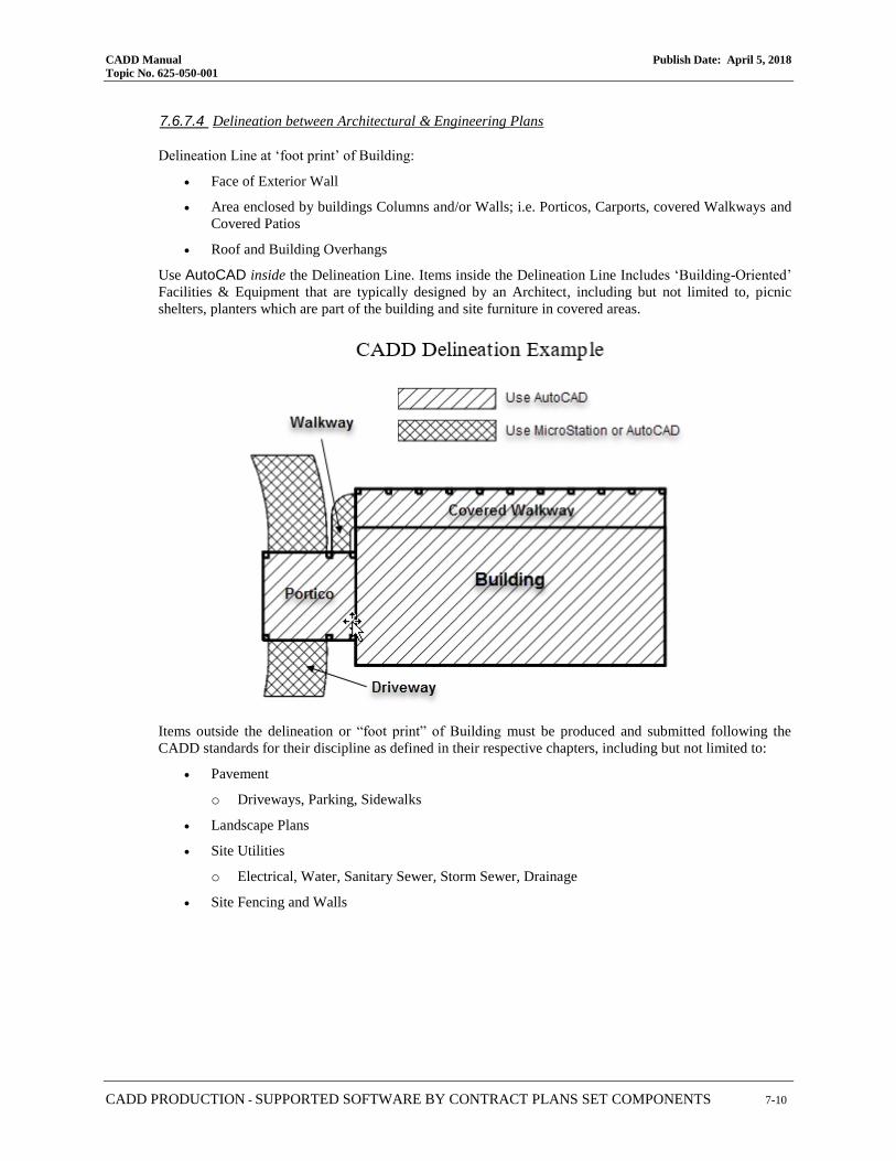
CADD Manual Publish Date: April 5, 2018
Topic No. 625-050-001
CADD PRODUCTION - SUPPORTED SOFTWARE BY CONTRACT PLANS SET COMPONENTS 7-10
7.6.7.4 Delineation between Architectural & Engineering Plans
Delineation Line at ‘foot print’ of Building:
• Face of Exterior Wall
• Area enclosed by buildings Columns and/or Walls; i.e. Porticos, Carports, covered Walkways and
Covered Patios
• Roof and Building Overhangs
Use AutoCAD inside the Delineation Line. Items inside the Delineation Line Includes ‘Building-Oriented’
Facilities & Equipment that are typically designed by an Architect, including but not limited to, picnic
shelters, planters which are part of the building and site furniture in covered areas.
Items outside the delineation or “foot print” of Building must be produced and submitted following the
CADD standards for their discipline as defined in their respective chapters, including but not limited to:
• Pavement
o Driveways, Parking, Sidewalks
• Landscape Plans
• Site Utilities
o Electrical, Water, Sanitary Sewer, Storm Sewer, Drainage
• Site Fencing and Walls

CADD Manual Publish Date: April 5, 2018
Topic No. 625-050-001
CADD PRODUCTION - SUPPORTED SOFTWARE BY CONTRACT PLANS SET COMPONENTS 7-11
7.6.7.5 Architectural Scale Chart
The following chart is intended to aid the user in determining the appropriate scale for placing the border and
text on a drawing based on the actual size of the drawing. Calculations are based on a 9 1/2" x 15 1/2"
drawing area inside the border.
Note Sheet files must be assembled in paper space & printed at 1:1
Drawing Scales for Sheets
Architectural Scales Engineering Scales
Drawing Scale Plot Scale Drawing Scale Plot Scale
Full size 1 1” = 5’ 60
6” = 1’-0” 2 1” = 10’ 120
3” = 1’-0” 4 1” = 20’ 240
1 ½” = 1’-0” 8 1” = 30’ 360
1” = 1’-0” 12 1” = 40’ 480
¾” = 1’-0” 16 1” = 50’ 600
½” = 1’-0” 24 1” = 100’ 1200
3/8” = 1’-0” 32 1” = 200’ 2400
¼” = 1’-0” 48 1” = 500’ 6000
3/16" = 1'-0" 64 1” = 1000’ 12000
1/8” = 1’-0” 96 1” = 1250’ 15000
3/32" = 1'-0" 128 1” = 2500’ 30000
1/16” = 1’-0” 192 1” = 5000’ 60000
➢ FORMULAS:
AS = 12 x Drawing Scale, Ex. 1" = 10', then 12 x 10 = 120, Therefore AS = 120.
Structures
The use and generation of CADD files by Structures in regards to the Department’s Projects must be in
accordance with the general standards for all disciplines, unless superseded by instructions contained within this
section. The following table defines the resource files and features used for the FDOT Structures Workspace.
FDOT Structures Manual
Feature Bentley Autodesk
Color Table Color.tbl Not Applicable
Font Files FDOT*.ttf FDOT*.ttf
Level Definitions Strslevels.dgnlib StructuresTemplateDetail.dwt
StructuresTemplatePlan.dwt
Main Cell/Block Library TTF_V8Structures.cel Structures.dwg
Models Allowed Yes Not Applicable
QC Rule Spst10 Spst10
Seed/Template Files StructuresSeed.dgn
StructuresSeed3d.dgn StructuresTemplateDetail.dwt
StructuresTemplatePlan.dwt
Text / Dimension Styles Definitions
Strslevels.dgnlib StructuresTemplateDetail.dwt
StructuresTemplatePlan.dwt

CADD Manual Publish Date: April 5, 2018
Topic No. 625-050-001
CADD PRODUCTION - SUPPORTED SOFTWARE BY CONTRACT PLANS SET COMPONENTS 7-12
7.6.8.1 Structures Borders and Scales
➢ Borders:
Draw all elements at "Full Size" completely before placing text or dimensions. Sheets that reside in the
Structures Component of the plan set must use the Structures Border cell “Sheet-Border”. Sheets requiring
Structures design that reside within other discipline components of the plan set (Roadway, Lighting, etcetera)
must use the Border Roadway w/Initials cell “Sheet-Rdwy”.
Show the scale of the drawing and related details inside the display area of the file, but outside of the Sheet
Border area. This is helpful to all users who work on the file.
➢ Scales:
The following chart is intended to aid the user in determining the appropriate scale for placing the border and
text on a drawing based on the actual size of the drawing. Calculations are based on a 9.60" x 15.40” drawing
area inside the border.
• Architect’s Scales
Drawing Scale Active Scale (AS) Height (FT.) Width (FT.)
1/16" = 1' 192 153.59 246.39
3/32" = 1' 128 102.40 164.26
1/8" = 1' 96 76.80 123.20
3/16" = 1' 64 51.20 82.13
1/4" = 1' 48 38.40 61.60
3/8" = 1' 32 25.60 41.07
½" = 1' 24 19.20 30.80
3/4" = 1' 16 12.80 20.53
1" = 1' 12 9.60 15.40
1 ½" = 1' 8 6.40 10.27
3" = 1' 4 3.20 5.13
6" = 1' 2 1.60 2.57
1 = 1 1 .80 1.28
• FORMULAS: Architect’s Scale:
AS = 12 / Drawing Scale (Ex. 1/4" = .25in., then 12/.25 = 48, Therefore AS = 48)
W = Sheet Width (in.) / Drawing Scale (Ex. 1/4" = .25in., then 15.36/.25 = 61.44, Therefore W = 61.44)
H = Sheet Height (in.) / Drawing Scale (Ex. 1/4" = .25in., then 9.72/.25 = 38.88, Therefore H = 38.88)
• Engineer’s Scales
Drawing Scale Active Scale (AS) Height (FT.) Width (FT.)
1” = 500’ 6000 4799.81 7699.69
1” = 400’ 4800 3839.85 6159.75
1” = 300’ 3600 2879.88 4619.82
1” = 250’ 3000 2399.90 3849.85
1” = 200’ 2400 1919.92 3079.88
1” = 150’ 1800 1439.94 2309.91
1” = 120’ 1440 1161.95 1847.93
1” = 100’ 1200 959.96 1539.94
1” = 80’ 960 767.97 1231.95
1” = 60’ 720 575.98 923.96
1” = 50’ 600 479.98 769.97
1” = 40’ 480 383.98 615.98
1” = 30’ 360 287.99 461.98
1” = 20’ 240 191.99 307.99
1” = 15’ 180 143.99 230.99
1” = 10’ 120 96.00 153.99

CADD Manual Publish Date: April 5, 2018
Topic No. 625-050-001
CADD PRODUCTION - SUPPORTED SOFTWARE BY CONTRACT PLANS SET COMPONENTS 7-13
• FORMULAS: Engineer’s Scale:
AS = 12 x Drawing Scale (Ex. 1”=500’, then 12 x 500 = 6000, Therefore AS = 6000)
W = Sheet Width (in.) x Drawing Scale (Ex. 1”=500’, then 15.36 x 500 = 7680, Therefore W = 7680)
H = Sheet Height (in.) x Drawing Scale (Ex. 1”=500’, then 9.72 x 500 = 4860, Therefore H = 4860)
7.6.8.2 Structures Dimension Settings
Dimension styles are defined in the strslevels.dgnlib (MicroStation) or Structures Template files
(AutoCAD). Styles are provided for Dimensioning and Notes for various terminators and leaders. Make
every effort to use automatic dimensioning with element association enabled.
7.6.8.3 Existing Bridge Plans
Existing Bridge plan sheets must be submitted in PDF format, not DGN, and manually inserted into the plans
using sheet numbers. The January 2017 FDOT Structures Manual Section 3.1 B states the following:
“….At the end of the plan set, place all existing bridge sheets for each bridge in one PDF file named
"B1ExistingPlans.pdf" for the first bridge (number sheets sequentially "BX1-1", "BX1-2", etc.) and
"B2ExistingPlans.pdf" for the second bridge, etc."
Traditionally existing Bridge Plans have been made as a part of the contract documents and therefore should
be made part of the plans set; likewise, the PDF file(s) representing the existing Bridge Plans would reside
in the \struct\ project folder.
Note The person responsible for assembling the plan set including existing bridge plans may wish to apply a stamp on each existing bridge plan sheet that indicates “FOR INFORMATION ONLY” and the current contract FPID being designed.
Toll Facilities
As per the FDM 301, Toll Facility Plans should be prepared in accordance with the Florida’s Turnpike Enterprise
current General Tolling Requirements (GTR) found at the following link:
http://www.floridasturnpike.com/design/gtr.html
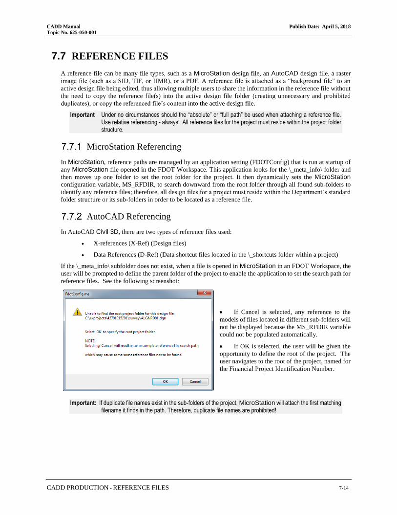
CADD Manual Publish Date: April 5, 2018
Topic No. 625-050-001
CADD PRODUCTION - REFERENCE FILES 7-14
7.7 REFERENCE FILES
A reference file can be many file types, such as a MicroStation design file, an AutoCAD design file, a raster
image file (such as a SID, TIF, or HMR), or a PDF. A reference file is attached as a “background file” to an
active design file being edited, thus allowing multiple users to share the information in the reference file without
the need to copy the reference file(s) into the active design file folder (creating unnecessary and prohibited
duplicates), or copy the referenced file’s content into the active design file.
Important Under no circumstances should the “absolute” or “full path” be used when attaching a reference file. Use relative referencing - always! All reference files for the project must reside within the project folder structure.
MicroStation Referencing
In MicroStation, reference paths are managed by an application setting (FDOTConfig) that is run at startup of
any MicroStation file opened in the FDOT Workspace. This application looks for the \_meta_info\ folder and
then moves up one folder to set the root folder for the project. It then dynamically sets the MicroStation
configuration variable, MS_RFDIR, to search downward from the root folder through all found sub-folders to
identify any reference files; therefore, all design files for a project must reside within the Department’s standard
folder structure or its sub-folders in order to be located as a reference file.
AutoCAD Referencing
In AutoCAD Civil 3D, there are two types of reference files used:
• X-references (X-Ref) (Design files)
• Data References (D-Ref) (Data shortcut files located in the \_shortcuts folder within a project)
If the \_meta_info\ subfolder does not exist, when a file is opened in MicroStation in an FDOT Workspace, the
user will be prompted to define the parent folder of the project to enable the application to set the search path for
reference files. See the following screenshot:
• If Cancel is selected, any reference to the
models of files located in different sub-folders will
not be displayed because the MS_RFDIR variable
could not be populated automatically.
• If OK is selected, the user will be given the
opportunity to define the root of the project. The
user navigates to the root of the project, named for
the Financial Project Identification Number.
Important: If duplicate file names exist in the sub-folders of the project, MicroStation will attach the first matching filename it finds in the path. Therefore, duplicate file names are prohibited!

CADD Manual Publish Date: April 5, 2018
Topic No. 625-050-001
CADD PRODUCTION - EXISTING AS BUILT PLAN SHEETS 7-15
Sharing of CADD Files
Every project utilizes the standard folder structure regardless of the project requirements. Data for each discipline
is maintained in their respective sub-folder. If a discipline requires information from another discipline, the
needed file(s) must be referenced from the original folder, not copied.
For example, the Signing and Pavement Marking design file (DSGNSP) references the Roadway design file
(DSGNRD) and the Topography file (TOPORD). These files should not be copied into the Signing and Pavement
Marking discipline sub-folder.
7.8 PROJECT JOURNAL
A Project Journal must be produced for all projects to document details on project data, design aspects, processes
and decisions made during the development that would communicate important information to a down-stream
user of the project data. The Journal must be delivered with the Project in either MS Word (.doc or .docx), text
(.txt), or Acrobat (.pdf) formats.
The Project Journal file(s) may be delivered to document the activities for a given discipline (i.e. a Surveyor’s
Journal), or may be created to document a particular production activity (i.e. creating cross sections). Journal
file entries should document alternate methods employed, variant decisions made, problems encountered, setting
selected, fixes included or other issues encountered during the production process outside the normal course of
operations.
For example: If custom line styles were created, the justification for the custom line style and the resource file
name containing the custom line style should be documented in the Journal. Any information that would help in
the regeneration of CADD files and / or prints should be recorded. The critical geometry information, database,
controlling alignment(s) and profile names, relevant survey and cross section information and the methodology
used to obtain the final geometric controls in the CADD product should be recorded.
7.9 EXISTING AS BUILT PLAN SHEETS
In some cases, designers have no choice but to scan pre-existing hardcopy sheets to create digital sheet files. For
example, some plan sheets may already exist as hardcopies and were signed & sealed conventionally by wet ink
signature and impression seal at some time in the past. This might occur when either pre-existing plans are
incorporated into the current delivery, or some professional discipline does not have legal authority to sign and
seal their plans digitally. In such cases, those plan sheets should be scanned to an acceptable PDF format
according to FDM 130.

CADD Manual Publish Date: April 5, 2018
Topic No. 625-050-001
CADD PRODUCTION - PROFESSIONAL OF RECORD NOTE 7-16
7.10 PROFESSIONAL OF RECORD NOTE
For those sheets that are digitally signed and sealed by a Professional Engineer, the following note must be placed
legibly on the sheet, typically along the right-hand border of the sheet opposite of the binding location:
Note See the FDM 130, for further information.
“THE OFFICIAL RECORD OF THIS SHEET IS THE ELECTRONIC FILE DIGITALLY SIGNED AND SEALED UNDER RULE 61G15-23.004, F.A.C.”
Note For additional information about Professional of Record Note and Signature Sheets also see the FDM Part 3, Chapter 302 & 303.
The regulatory Board Rule number referenced is determined by the discipline of the professional that is signing
and sealing:
❖ Surveyors and Mappers, the Rule is 5J-17.062, F.A.C.
❖ Geologists, the Rule is 61G16-2.005, F.A.C.
❖ Landscape Architects, the Rule is 61G10-11.011, F.A.C.
❖ Registered Architects, the Rule is 61G1-16.005, F.A.C.
Sheets that are signed by multiple Signatories of different professional types (such as an Architect and an
Engineer) will not bear the note unless it can be combined and fit legibly on the border. In such a case, the note
might read:
“THE OFFICIAL RECORD OF THIS SHEET IS THE ELECTRONIC FILE DIGITALLY SIGNED AND SEALED UNDER RULE 61G15-23.004, F.A.C., AND RULE 61G1-16.005, F.A.C.”
Signatory Sheets have similar notes placed within the body of the sheet within the section for each Signatory,
and will not have the note placed along the sheet border. See examples in the FDM 303.
The Professional of Record Note may be placed on the sheet at any time during the plans production process,
however has no force or effect until the sheet is actually signed and sealed.
MicroStation
CELL LIBRARIES AutoCAD
BLOCK DRAWINGS DESCRIPTION
Seals.cel Seals.dwg Professional Seals for Digital Signatories

CADD Manual Publish Date: April 5, 2018
Topic No. 625-050-001
CADD DELIVERY - RECEIPT AND ACCEPTANCE OF ELECTRONIC DATA 8-1
CADD DELIVERY
8.1 PURPOSE
This chapter establishes the minimum requirements and functions necessary for Florida Department of
Transportation (Department) Computer Aided Design and Drafting (CADD) project review and delivery process.
8.2 SCOPE
This chapter outlines the Department’s functions to review, package, and distribute electronic files included in a
CADD project for the Department.
8.3 RECEIPT AND ACCEPTANCE OF ELECTRONIC DATA
The Project Manager is responsible for ensuring that the terms of the scope of services of a project have been
met, including the assurance that the Department’s Quality Control (QC) requirements were fulfilled during
production of the electronic data.
➢ Translation of Files
The Department requires MicroStation DGN format (V8 and higher) or AutoCAD .DWG format (2014 or
higher) for the delivery of all design files, except as specifically defined herein this document for specific
disciplines.
The data producer is solely responsible for any translation required for delivery to the Department, including
the accuracy of translation of the design files and adherence to the standards and specifications, and the
validity of the geometric elements contained in the CADD Manual.
➢ Receipt of Data
The Project Manager must receive electronic data under a letter of transmittal.
➢ Acceptance
The Project Manager ensures that the delivery is checked for completeness and meets the terms, conditions
and requirements outlined herein. Once the delivery has been determined to be compliant, a record of
acceptance must be made.
➢ Validation
Upon receipt of the delivery media, the Department will validate all digitally signed files.

CADD Manual Publish Date: April 5, 2018
Topic No. 625-050-001
CADD DELIVERY - PRODUCTION DELIVERABLE FILES 8-2
8.4 PRODUCTION DELIVERABLE FILES
Plans will be divided by plans components. The Department’s Standard Plans Component codes (corresponding
to the component order defined in the FDM 301 are as follows:
01 – Roadway Plans
02 – Signing and Pavement Marking Plans
03 – Signalization Plans
04 – Intelligent Transportation System Plans
05 – Lighting Plans
06 – Landscaping Plans
07 – Architectural Plans
08 – Structures Plans
09 – Toll Facilities
10 – Utility Work by Highway Contractor Agreement Plans
Plans Component PDF Files
Each plan component will be delivered as a separate PDF file. Component file PDFs will have one of the
applicable file names from the table below.
fpid-PLANS-01-ROADWAY.PDF fpid-PLANS-06-LANDSCAPE.PDF
fpid-PLANS-02-SIGNINGMARKING.PDF fpid-PLANS-07-ARCHITECHTURAL.PDF
fpid-PLANS-03-SIGNALIZATION.PDF fpid-PLANS-08-STRUCTURES.PDF
fpid-PLANS-04-ITS.PDF fpid-PLANS-09-TOLLFACILITIES.PDF
fpid-PLANS-05-LIGHTING.PDF fpid-PLANS-10-UTILITYWORK.PDF
Each Plans Component PDF will contain all of the sheets in that component set in consecutive order and suitable
for inclusion into the overall plan set. The only exception to this requirement is Early Work sheets discussed in
Section 8.10.1 of this document.
Each Plans Component PDF will have its own key sheet. In the event that there is more than one professional
of record signing a plan component, a signature sheet(s) will be inserted directly behind the key sheet to contain
the digital signatures. If a plan component or an early work sheet has only one professional of record signing,
then NO signature sheet will accompany that component or Early Work sheet. In the instance of a single signer
the digital signature appearance will be placed on the lead sheet in the set in the same location as a physical wet-
ink signature and seal would appear; on the key sheet for a component set or the first sheet for an Early Work
sheet set.
Produce Plan Component PDF’s and Early Works Sheets in Black and White or Grayscale, unless color PDFs
are required. Production of the PDF in color enlarges the file size considerably. All plans sheets must be
produced in the PDF in the same reading orientation, preferably Landscape, with the title block displaying at the
bottom of the sheet.
Note For strung projects, each “Lead” and “Goes-with” Project dataset and Bid Set data is delivered separately. Each “lead” and “Goes-with” will have its own set of PDFs, fpid-CADD.ZIP, etcetera.

CADD Manual Publish Date: April 5, 2018
Topic No. 625-050-001
CADD DELIVERY - PRODUCTION DELIVERABLE FILES 8-3
8.4.1.1 Early Work Sheets of Plan Sets
Portions, certain Early Works sheets, of a plan set that are delivered early in the project development cycle
as per the FDM 130.2.1 and FDM 302.6.1 may be digitally signed at the time of sheet development. In so
doing, the professional of record signs said Early Works sheets only once when those sheets are completed,
unless subsequent changes are made to the sheets.
Early Works may only be provided in one of four instances; Project Control, Geotechnical Core Borings,
Verification of Underground Utilities Survey, or a Tree Survey. Each Early Work set is provided as a separate
multi-sheet PDF file. Those PDF files will be named accordingly using the following file naming convention:
Project Control: <fpid>-PLANS-<component code>-<component>-PC.PDF
Geotechnical Core Borings: <fpid>-PLANS-<component code>-<component>-COREBORINGS.PDF
Underground Utilities: <fpid>-PLANS-<component code>-<component>-VERIFIEDUTILITIES.PDF
Tree Survey: <fpid>-PLANS-<component code>-<component>-TREESURVEY.PDF
Typically, these are delivered with the roadway component. An example where the primary plans component
is roadway (01-ROADWAY), early works are delivered is shown in the following table:
fpid-PLANS-01-ROADWAY-PC.PDF
fpid-PLANS-01-ROADWAY-COREBORINGS.PDF
fpid-PLANS-01-ROADWAY-VERIFIEDUTILITIES.PDF
fpid-PLANS-01-ROADWAY-TREESURVEY.PDF
As another example, if the primary plans component is structures (08-STRUCTURES), then the early work
sheets will be named as shown in the following table:
fpid-PLANS-08-STRUCTURES-PC.PDF
fpid-PLANS-08-STRUCTURES-COREBORINGS.PDF
fpid-PLANS-08-STRUCTURES-VERIFIEDUTILITIES.PDF
fpid-PLANS-08-STRUCTURES-TREESURVEY.PDF
And likewise other plans components.
8.4.1.2 Plans Component PDF Deviation
In the rare event that the complexity and sheer size of a project dictates that the project be further subdivided
than by the means provided by the above file names, an approval may be granted as follows:
• A request to deviate from the required process must be made in writing by the District Plans,
Specification & Estimates Engineer to the Central Office, Program Management Office.
• The request must be specific regarding the proposed file structure and delivery method that will be used
for the project in question.
• The request should be made as early in the design phase as practical, but no later than Phase III Plans
Submittal.
• Central Office, Program Management Office will grant approval if the need for deviation is
demonstrated and the proposed process is acceptable.
• An approval granted on one project may not be construed as to extend to other projects regardless of
similar circumstances. Approvals are granted on a project by project basis.

CADD Manual Publish Date: April 5, 2018
Topic No. 625-050-001
CADD DELIVERY - PRODUCTION DELIVERABLE FILES 8-4
3D Model PDF Files
All projects modeled in 3D will deliver a separate 3D PDF file. Project file PDFs will have the file name as
shown below.
• fpid-3DMODEL.PDF
Specifications PDF Files
• fpid-SPECS.PDF – Specifications PDF format file delivered separate from the project folder
structure. This file is signed and sealed with Digital Signature.
• fpid-SPECS-SUPP##.PDF – Supplemental Specifications file signed and sealed with Digital
Signature.
Note Refer to Chapter 5.7.1.3, Specifications Standards - Technical Special Provisions (TSPs) in the Bid Set.
CAD ZIP Files
An archive of the Project folder structure containing the CADD files (Native DGN’s / DWG’s of the platform
used to design the project) and supporting data files from which the final plans were developed will be delivered
in the format of a ZIP file (fpid-CADD.ZIP). This ZIP file is not signed and sealed and is delivered as a separate
file outside of the project folder structure.
The designer must determine which files should be included inside the fpid-CADD.ZIP file to support the plans
and facilitate the contractor constructing the project. The folder structure inside fpid-CADD.ZIP closely
resembles the Project Folder structure (as a sub-set), where files found in fpid-CADD.ZIP would be found at the
same path as in the project Folder structure.
As a minimum, the fpid-CADD.ZIP should include:
• CADD Drawing Files (DGNs, DWGs, etcetera)
• Engineering Data Files (described later in this chapter and prior chapters)
• Summary of Quantity Sheet Backup Drawings (includes data such as, shapes and area identifications)
• 3D Deliverable Files (a culling out of selected CADD and other files from the Project CD specifically for the contractor)
DO NOT include the following files (and their variants) in the fpid-CADD.ZIP:
• fpid-PLANS-<component code>-<component>.PDF
• fpid-PLANS-<component code>-<component>-REV##.PDF
• fpid-SPECS[-].PDF
• fpid-SPECS-SUPP##.PDF
Note Because fpid-CADD.ZIP does not represent the entire Digital Delivery, certain tools, such as FileChecker, should not be run against only the contents within fpid-CADD.ZIP. FileChecker should only be run against the full Project folder structure containing all of the Digital Delivery.

CADD Manual Publish Date: April 5, 2018
Topic No. 625-050-001
CADD DELIVERY - PRODUCTION DELIVERABLE FILES 8-5
8.4.4.1 Engineering Data
In addition to the delivery of the files produced during development, the Department requires the inclusion
of certain Engineering Data files for critical geometrics in the design. These can include the alignments,
profiles, cross sections, and surfaces. Critical roadway geometric items, such as the centerlines and profiles
of the proposed mainline, side streets, special ditches, and utilities, must be included.
Project design documentation (like pavement design report, typical section package, exceptions, variations,
architectural calculations, drainage calculations, lighting design analysis report, permits, geotechnical
reports, structural calculations, toll facility calculations, utility schedules, etcetera) will be delivered per
FDOT Design Manual (FDM) 111.7. Some districts specify these documents be delivered under \admin\ or
\calcs\ specific project folders.
➢ Plan Summary Boxes and Quantity Files
The Plan Summary Boxes and supporting quantity calculations files must be delivered according to the
guidelines and formats defined by MicroStation Basics for Construction.
➢ Structures Engineering Data
Under the project \struct\ folder, create separate sub-folders for each bridge and/or structure in the project.
Name these sub-folders using the sheet prefix and bridge numbers (when applicable) and locate the
MicroStation design files for each bridge under these sub-folders. (e.g...\struct\B\; \struct\B1-######\)
Under each bridge and/or structure sub-folder, create an \eng_data\ sub-folder for the Engineering Data
related to the design of the project. (e.g...\struct\B\eng_data\; \struct\B1-######\eng_data\). Computer input and output files include files used for all aspects of bridge, retaining wall, and/or miscellaneous structures design. These include, but are not limited to, files generated from the following computer programs:
• FDOT Structural Software • FBPier
• GTStrudl • LEAP Software
• STADD • BD2
• RISA • MDX
• Mathcad Spreadsheets • BC
• Excel Spreadsheets • Adapt
Under each of the \eng_data\ sub-folders for each bridge and/or structure in the
project, create subfolders for the applicable programs with two sub-folders:
\PDF\ and \Native\. Place the appropriate input and output files in each sub-
folder. Only sign and seal these PDF files when required by Contract.
Note For quantity calculations see Section 6.7.2.1 of this document.
8.4.4.2 3D Deliverables - Automated Machine Guidance in Construction
The project CADD.zip file includes a 3DDeliverables folder. This folder includes files provided to the
contractor for Automated Machine Guidance (AMG) in Construction. The Department has adopted basic
CADD and LandXML formats as the standard for delivery. These are typically not application files, e.g.
GEOPAK, OpenRoads or Civil3D. Contractors have requested the Department isolate the CADD and
LandXML files they would typically need with a consistent name scheme.

CADD Manual Publish Date: April 5, 2018
Topic No. 625-050-001
CADD DELIVERY - PRODUCTION DELIVERABLE FILES 8-6
The following table describes the file(s) to be provided for construction.
3D DELIVERABLES SUPPORTING AMG for 3D PROJECTS (Store in project folder: 3DDeliverables)
File Name Description
Design Alignments and Profiles
AMG-ALGN##.xml All Alignments and Profiles exported from the \Roadway\ALGNRD, PROF or
model files and \Roadway\DSGNRD or CORRRD files in LandXML format.
2D Proposed Planimetrics Design
AMG-2DSGN##.dwg/dgn 2D proposed Roadway design exported from the \Roadway\DSGNRD file.
(Production of this file for construction is at the designer’s discretion.)
AMG-2DRPR##.dwg/dgn 2D proposed Drainage design exported from the \Roadway\DRPRRD file.
(Production of this file for construction is at the designer’s discretion.)
AMG-2PDPL##.dwg/dgn 2D proposed Pond design exported from the \Roadway\PDPLRD file.
(Production of this file for construction is at the designer’s discretion.)
2D Existing Survey (Note: These are being considered to merge into a single survey Planimetrics file)
AMG-2TOPO##.dwg/dgn 2D proposed existing Topography exported from the \Survey\TOPORD file.
(Production of this file for construction is at the designer’s discretion.)
AMG-2DREX##.dwg/dgn 2D proposed existing Drainage exported from the \Survey\DREXRD file.
(Production of this file for construction is at the designer’s discretion.)
AMG-2UTEX##.dwg/dgn
2D proposed existing Utilities exported from the \Survey\UTEXRD file.
(Production of this file for construction is at the designer’s discretion.)
3D Existing Survey Surfaces
AMG-3SURFACEEX##.xml
3D existing terrain surface to be exported from the \Survey\GDTMRD file as
LandXML format.
(Production of this file for construction is at the designer’s discretion. This file
will be produced if the 3D Existing Surface dwg/dgn file(s) are not produced.)
AMG-3SURFACEEX##. dwg/dgn
3D existing terrain surface to be exported from the \Survey\GDTMRD file.
(Production of this file for construction is at the designer’s discretion. This file
will be produced if the 3D Existing Surface LandXML file(s) are not produced.)
3D Proposed Surfaces
AMG-3SURFACEPR##.xml 3D proposed finished (top) surface to be exported as LandXML format from the
\Roadway\MODLRD file.
AMG-3SURFACEEW##.xml
3D proposed finished (bottom) surface to be exported as LandXML format from
the \Roadway\MODLRD file. This file will be used to generate surface to
surface earthwork volumes.
3D Proposed Break Lines
AMG-3DSGN##.dwg/dgn
3D proposed Roadway design exported from the \Roadway\DSGNRD file.
(Production of this file for construction is at the designer’s discretion. This file
will be produced if the 3D Proposed Surface(s) LandXML file(s) is not
produced. Geometric elements should be in vector.)
Note All 3D Deliverable files should be set to ‘READ ONLY’. For more infomation on creating these files see Chapter 10 of FDOT Roadway Design and 3D Modeling training guide:
FDOT Roadway Design and 3D Modeling Training Guide
For the supporting documentation on 3D Deliverable files for Automated Machine Guidance see
FDOT 3D Deliverables Support Resource

CADD Manual Publish Date: April 5, 2018
Topic No. 625-050-001
CADD DELIVERY - PRODUCTION DELIVERABLE FILES 8-7
Merging External Project Files
Files must be merged into the main Project folder structure prior to the project delivery. These include CADD
system dependency files, and files provided from outside sources, such as those produced by sub-consultants.
➢ CADD System Dependency Files:
Certain CADD references might reside external to the project folder during the production phase. Before
delivery to the Department, these files must be placed in the appropriate locations within the Project folder
structure. It is strongly recommended that these files be included in the Project folder structure early on in
project development and verified that referencing functions work properly.
Note Reference files must also be attached without the “save full path” option, and should be located by their relative paths from the root of the Project folder.
For printing purposes, any user created custom line style/linetype, font resource, and cell / block library files
used for the project must be included with the project in the sub-folder \symb\. In addition, any external
design files that are referenced, such as sheet border files, must be copied to the project folder. This allows
the view or recreation of prints matching the original delivery for future customers of the data.
Note The designer does not need to include the Department’s standard CADD resources delivered in the Department’s CADD Software (either MicroStation or AutoCAD resources). However, the Department’s CADD Software version information must be provided in the Project Journal.
➢ Files from Outside Sources:
Files that come from an outside source include files produced by a sub-consultant. Files from sub-consultants
must be delivered to the primary consultant, or the Department’s designer, following the same requirements
for Delivery.
➢ Merging Previously Digitally Signed Documents:
Once a document is signed using a digital certificate, the document is valid when it is completely unaltered.
Merging two or more documents together, even if those documents are signed and completely valid
independently, produce a completely new document - thus an altered document. When merging previously
signed documents, the PDF editing software will strip off all digital signatures that have been applied.
In situations where it is necessary to merge previously digitally signed documents, retain the original signed
documents from which the merged document is produced. If it is necessary for the merged document to be
signed, then it must be signed by the original signatories or their successors.
Reviewing the Project
All Department Project deliveries must be provided to the Department’s Project Manager, unless an alternate
agreement is reached, along with a Compliance Certification Checklist (or similar document). A basic
Compliance Certification Checklist, sample found in Section 1.10.2 of this document, may be employed to help
the data producer consider critical items in their QC review for delivery.
Note Department’s Districts may use a more comprehensive Compliance Certification Checklist in their QA process than the example in this document. The Department prefers this or similar documentation of QC compliance be submitted digitally and included in the \admin\ or \data\ project sub-folders.
The Department’s CADD Software Suite provides tools (including QC Inspector and FileChecker) to help ensure
quality control which helps enable a successful review. One must use due diligence to make sure all delivery
requirements are met. It is the responsibility of the producer to perform a thorough review. This procedure does
not prescribe every potential item that might need to be checked.
➢ Example: Some items to review would include:
• Take particular care to look for missing sheets, gaps in the sheet numbering, duplicate sheet
numbering, etcetera. Check for misspellings in sheet borders and other grammatical errors.

CADD Manual Publish Date: April 5, 2018
Topic No. 625-050-001
CADD DELIVERY - PRODUCTION DELIVERABLE FILES 8-8
• Take particular care to find multiple files in the Project folder structure with the same file name, but
different content, which must be resolved. Likewise, find files with the same content, but different
filenames (which could occur as with the case of the files beginning with “AMG…” as described
previously).
• Make certain the Professional of Record Note appears on plan sheets indicating the source of the
official record.
• Ascertain whether the Component PDF’s and Early Works Sheets contains all sheets, in a properly
indexed order, and is scaled and rotated properly.
• Validate the digital signatures of signed files.
• Confirm that the Project Journal(s) are complete and accurate.
Sign and Seal Project Files
The Department requires a Digital Delivery process for the submittals of all CADD projects. This process uses
Digital Signature for documents and complies with Florida Administrative Code governing the specific
discipline for the professional signing those documents. Digital Delivery comprises two parts:
❖ One Part that represents the work product of design in the full project directory structure.
❖ One Part extracted from the full project directory structure that is provided to contractors as defined
herein.
The Department uses Digital Signature to secure files as defined in Florida Statutes 668.003. Digital Signature
is a “paperless” process that relies upon the intrinsic ability of the files themselves to encode cryptographic
security features using a Digital Certificate issued to the Professional of Record.
Regulated transactions, such as the development and submission of engineering plans, specifications, reports,
and surveys, require high assurance when signing documents. When documents are distributed electronically it
is important that recipients can:
❖ Verify document authenticity – confirming the identity of each person signing the document
❖ Verify document integrity – confirming that the document has not been altered
Certificate-based signatures provide both of these security services. The Department chose to use certificate-
based digital signature infrastructure using third party certificate authorities to provide independent identity
validation. Once certificate-based digital IDs are acquired by professional Signatories, PDF software can be
used to sign PDF files and validate files received from others. In addition, the Department provides a tool, XML
Signer, to digitally sign any XML based file with a Digital Certificate. Likewise, any applications that support
Digital Signature with public key infrastructure can be used to sign their respective files.
Digital Signature allows one to:
➢ Sign Documents:
• Sign PDF files using certificate IDs
• Place a signature box anywhere on the appropriate page or sheet
• Add multiple signatures to a document or page
• Add a time stamp to the document
• Certify a document with a visible (or hidden) signature to enable recipients to verify authenticity
with or without seeing a visible signature on the currently viewed page
• Automatically embed certificate data to support long-term validation
➢ Validate Documents:
• Validate all signatures, confirming the identity of everyone signing the document
• Validate document integrity by tracking all previously signed versions of a document to verify
changes made during the document’s lifecycle

CADD Manual Publish Date: April 5, 2018
Topic No. 625-050-001
CADD DELIVERY - PRODUCTION DELIVERABLE FILES 8-9
➢ Set Privileges and Permissions for Others:
• Certify a document while leaving portions available for form filling, additional signatures, or
comments
• Lock a PDF document with a Certificate ID to restrict editing or copying
Note Architectural Signing and Sealing - The Florida Department of Business and Professional Regulation (BPR) approved Architects to electronically sign and seal Plans and Specifications. Architects must use Digital Signature.
8.4.7.1 Digital Certificates
An Access Certificate for Electronics Services (ACES) digital certificate is used to ensure identity,
authenticity and accountability in citizen-to-government, business-to-government, and government-to-
government electronic transactions. An ACES digital certificate is an electronic identity issued by a
Certification Authority that establishes an individual’s identity per the Federal Government Services
Administration (GSA) standards when using electronic transactions. There are several 3rd party Certificate
Authorities that issue ACES certificates. The Department internally uses ACES certificates issued by
IdenTrust: http://www.identrust.com/fdot/index.html. The Department’s Office of Information Technology
(OIT) has recently adopted additional Certificate Authorities found here:
http://www.fdot.gov/it/ApprovedDigitalCertificateAuthorities.shtm
When applying Digital Signatures, many software applications allow the signature to have an “appearance.”
As a minimum, use an appearance with the text name of the Signatory and the date-time stamp at the instant
of signing. (See FDM 303.4)
❖ Do not include any additional watermark or overlay.
❖ Do not include an image of the “wet ink” signature of the Signatory (a violation of Board rules).
❖ Do not include company logos, or other images within the Digital Signature appearance.
The reason (text) for signing may be placed in a text block within the drawing where more space is available.
The image of an impression seal may also be included, but is not part of the Digital Signature itself. For the
Department’s Plans are provided with the CADD Software Suite that contain images of seals and may be
found in the Seals.cel or Seals.dwg Cell / Block Library(s).
ACES Digital Certificates uniquely identify an individual. As such, these certificates must be closely guarded
against unauthorized usage. Digital Certificates used for signing and sealing must be “Under the sole control
of the person using it”, as stated in Florida Administrative Code 61G15-23.004and others. Install certificates
using “High” security options and disallow exportation of certificates from the primary Professional of
Record (POR) workstation. The POR may not “delegate” the use of a digital certificate by sharing a
certificate, sharing a password, or otherwise compromising sole possession and use of the certificate.
8.4.7.2 Multiple Signature Sheets
In situations where there are multiple signatories for a plan set where there are too many to list on a single
signature sheet, multiple signature sheets may be added to the plan set. All signature sheets for a given
component must be placed successively after the component Key Sheet.
Please refer to the Department’s FDM Chapter 303 for examples:
http://www.fdot.gov/roadway/FDM/
Note Finished sheets digitally signed and sealed must bear the Professional of Record Note as shown in the Department’s FDM Exhibits. The note must be applied before signing and sealing and final delivery.
8.4.7.3 Securing the Project for Delivery
Digitally signed documents have the security key information embedded in the files themselves. Digitally
signed files are secured and authenticated using commercially available software (Adobe, Bluebeam, and
etcetera).

CADD Manual Publish Date: April 5, 2018
Topic No. 625-050-001
CADD DELIVERY - PRODUCTION DELIVERABLE FILES 8-10
Legacy Electronic Signature Projects
Provenance and uninterrupted legal record of the project data must occur, whether it be by product or
management practice. Therefore, it is important that both the data producer and the Department make a sensible
effort to ensure the documents supporting the digital signing and sealing of files by a professional signatory and
the securing of the delivery be preserved in a manner consistent with those responsibilities under the rules of the
Boards of Professional Regulation in Florida.
For projects that were once performed under the old Electronic Delivery process, the Department will maintain
the paper copies of tention Signature and Manifest documents until it is determined how these records may be
preserved in other media that meets the requirements of the Florida Boards of Professional Regulation.
Media Requirements for Delivery
All electronic projects submitted to the Department must be on write protected physical media (CD-ROM or
DVD-ROM) unless otherwise approved by the Department’s District Plans, Specifications & Estimates (PS&E)
Manager or Program Management Administrator. Use only 1st Class archival quality writable media.
If the project is too large to fit on one CD/DVD, then the process for delivery to the Department’s must be
reviewed with the Department’s Project Manager before splitting the project on multiple CD/DVDs or choosing
an alternate media. If approved by the appropriate authority other means of transmission of data, such as File
Transfer Protocol (ftp) or File Transfer Appliance (FTA) may be used.
All Physical Project Media Must have a Project Identification Label with the Following:
• Financial Project ID Number of Project
• Project Description (including County and State Road numbers, local road designation)
• Firm or District Performing the Work
• Name of the Department and Consultant Project Manager(s)
• Creation Date of the Media
• Disk (#) of (Total #) (if multiple ROMs are needed)
• Delivery Type Label (Project CD, Bid CD, etcetera)
• Anticipated Letting Date for the Project
With the increase of storage capacity and more cost efficiency of USB removable memory drives (thumb drives),
use of this media will grow in popularity for the Department’s Deliveries.
➢ If memory drives are used:
• The physical drive must be labeled with the Project Identification (fpid) number and District as
a minimum.
• A text file must be included on the media’s root folder (not Project folder) containing the Project
Identification label information and Transmittal Letter containing the same.
Compliance Certification Checklist
All Department Project deliveries must be provided to the Department’s Project Manager, unless an alternate
agreement is reached, along with a Compliance Certification Checklist (or similar document).
Note Department’s Districts may use a more comprehensive form in their QA process than the following example. The Department prefers this or similar documentation of QC compliance be submitted digitally and included in the \admin\ or \data\ project sub-folders.
All electronic data submittals are to be transmitted to the Department’s Project Manager. At a minimum, the
questions provided in the sample form found in Section 1.10 of this document must be addressed before
submittal, and this (or a similar checklist) will be given to the Project Manager along with the submittal.

CADD Manual Publish Date: April 5, 2018
Topic No. 625-050-001
CADD DELIVERY - SPECIFICATIONS 8-11
8.5 SPECIFICATIONS
Specifications must be prepared in accordance with the Program Management policies and procedures. Statewide
implemented specifications files are distributed by the State Specifications Office through the District
Specifications Offices.
For Digital Delivery Bid Sets, the Specification files are copied from the \specs\ sub-folder structure for delivery.
Specification file naming convention for Digital Delivery submittals is: fpid-SPECS[-].pdf:
fpid = full (11digit) Financial Project Identification Number without dashes.
SPECS = item description
[-] = any additional naming specific to the project (optional)
Supplement file naming convention for submittals is: fpid-SPECS-SUPP##[-].pdf, where:
fpid = full (11digit) Financial Project Identification Number without dashes,
SPECS = item description
SUPP = Identifier
## = sequential numbering of the supplements: 01, 02, 03, etcetera
[-] = any additional naming specific to the project (optional)
BOE# = Bases of Estimates – Pay Item number
TSP = Technical Special Provision
Original Delivery Supplement1 Supplement2
fpid-SPECS[-].PDF fpid-SPECS-SUPP01[-].PDF fpid-SPECS-SUPP02[-].PDF
fpid-SPECS-TSP[BOE#][-].PDF fpid-SPECS-TSP[BOE#]-SUPP01[-].PDF fpid-SPECS-TSP[BOE#]-SUPP02[-].PDF
For Example: Begin with the FPID number, then the item description (SPECS), then supplement number
(SUPP##), and finally any naming [-] specific to the project (optional).
This file naming convention allows project files to collate as sorted and combined in a single folder. Text,
numbers and dashes are allowed. Characters that interfere with operating system path specifications or XML
paths must be excluded, such as underline and spaces and (/ \ . : , < & # >).
➢ Technical Special Provisions
When the use of a Technical Special Provision (TSP) is authorized by the District Specifications Office, the
PDF of the TSP file(s) is individually signed and sealed and also becomes part of the overall project’s
Specifications package.
For Digital Delivery, certificate based Digital Signature must be used.
The TSP must include the electronic statement incorporated on the TSP cover page. When a TSP is manually
signed and sealed, it must be scanned in grey scale for seal visibility and no electronic statement is needed.
When TSPs are combined into the overall Specification package, the Signatory(s) of the TSPs do not have to
re-sign the combined documents. Add the image of the seal to the cover page of each TSP. The individual
files for each TSP must be digitally signed and sealed.
➢ File Structure (Specs Only Projects)
• Specifications Folder Structure
• Supplemental Specifications Folder Structure
• Technical Special Provisions (TSP)*

CADD Manual Publish Date: April 5, 2018
Topic No. 625-050-001
CADD DELIVERY - SPECIFICATIONS 8-12
Note If a TSP is applicable to the project, then the folder for TSP(s) would apply to both the Project CD and Bid CD data set. Multiple TSP files may exist in the delivery.
The Specification Package is delivered as fpid-SPECS.pdf. Subsequent TSPs are delivered as
fpid-SPECS-TSP[BOE#].pdf as shown in Chapter 5.8.
1. Create the project folder using all eleven digits of fpid Number. (i.e., 12345678900).
2. Inside the created (project) \FPID\ folder. This is where the Specifications package file
(fpid-SPECS[-].pdf) is placed.
3. For Supplements, continue to use the ORIGINAL \FPID\ folder created in Step 1.
4. For Supplements. This is where the Supplement package file (fpid-SPECS-SUPP##[-].pdf) is
placed.
5. Use digital signature to sign and seal the Supplement package file (fpid-SPECS-SUPP##[-].pdf).
Note DO NOT re-submit the entire Specification package for a Supplemental.
fpid
fpid-SPECS[-].pdf fpid-SPECS-TSP[BOE#][-].pdf fpid-SPECS-TSP[BOE#][-].pdf
Example of a
Specifications Only Package
Folder Structure
Note: The fpid is the Project’s Financial
Project Identification Number
fpidSUPP#
fpid-SPECS-SUPP##[-].pdf fpid-SPECS-TSP[BOE#]-SUPP##[-].pdf fpid-SPECS-TSP[BOE#]-SUPP##[-].pdf
Example of a
Supplemental Specifications Only Package Folder
Structure
Note: The fpid is the Project’s Financial Project
Identification Number

CADD Manual Publish Date: April 5, 2018
Topic No. 625-050-001
CADD DELIVERY - FINAL PLANS OFFICE 8-13
8.6 FINAL PLANS OFFICE
Final Plans is division of the Program Management Office responsible within the Department for preparing and
posting project deliverables for contract letting documents. This includes the packaging of all CADD data for
the Plans, Specifications and Estimates (PS&E) Submittal contained in a project.
Final Plans involves the review and acceptance of a Delivery and making that Delivery available to the
Department’s internal services for posting. Functions include: receipt and authentication of delivery media and
placement of project data into systems for general use.
Upon receipt of the secured Delivery package and the accompanying documents, the Compliance Certification
Checklist(s) must also be reviewed for completion and the signed files must be opened and authenticated.
Note Following the requirements within this manual does not guarantee an acceptable work product, as this procedure does not address the quality of the engineering or survey work performed.
Once the Delivery is accepted, the electronic project will be imported into the Department’s file management
systems for subsequent use. (See FDM 131.5 Retention of Electronic Documents). Various stakeholders such as
Construction and Maintenance have access to submittals via the Department’s file management system
➢ Contract Packaging
Final Plans must coordinate regarding contract packaging requirements for a delivery for a letting found in the
FDOT Design Manual.
The Contract Package is made available to contractors for bidding during the advertisement period and generally
includes:
• Plans Component PDF file(s) representing the Plans Set
• Specifications PDF file(s)
• Archival native CADD ZIP file (including Automated Machine Guidance files)
➢ Publication and Distribution
Final Plans is responsible for publication and distribution of electronic data in accordance with procedures or
requests, including but not limited to publishing electronic data to different media.
➢ Archive and Security of Data
Final Plans must insure that prescribed safeguards for the data have been met and the archival package for data
includes all electronic data available for a project. The data must be preserved where it can be retrieved at future
dates, meeting records retention standards set for such data.
Please use the hyperlink below for additional information regarding the Department’s Plans, Specifications and
Estimates (PS&E).
http://www.fdot.gov/programmanagement/FinalPlans/

CADD Manual Publish Date: April 5, 2018
Topic No. 625-050-001
CADD DELIVERY - STRUNG PROJECTS 8-14
8.7 REVISIONS
Revisions to the Department’s projects require the files that have changed since the previous delivery. Revision
files use the original file name with a “-REV##” suffix after the file type; CADD, PLANS, SPECS.
As an example, the first revision to a Roadway Component will be named as follows:
fpid-PLANS -01-ROADWAY-REV01.PDF
The first revision to Project Control, Early Work sheets as part of a Roadway Component, for example, will be
named as follows:
fpid-PLANS -01-ROADWAY-PNC-REV01.PDF
A second revision will have a “REV02” suffix, third revision will have a “REV03” suffix, and so forth.
The designer must deliver:
❖ Ensure the Department has a complete copy of the original Delivery:
o The native CADD files delivery fpid-CADD.ZIP
o The plan component PDF files fpid-PLANS-[component code-component].PDF
o The initial specifications document fpid-SPECS.PDF
o The initial Technical Special Provisions fpid-SPECS-TSP[BOE#].PDF
❖ The Revision: (The Bid Set must only contain the changed files in the revision/supplement.)
o fpid-CADD-REV01.ZIP
o fpid-PLANS-[component code-component]REV01.PDF
o fpid-SPECS-SUPP01.PDF
o fpid-SPECS-TSP[BOE#]-SUPP01.PDF.
❖ The complete Project folder structure with all contemporary files included.
8.8 RE-LET PROJECTS AND ROLL BACK REVISIONS
In rare cases, the Department must Re-Let a project. If no revisions have occurred to the project set for Re-
Letting, the Department will simply re-advertise and Let the project with the submitted Project CD or Bid Set
CD data. However, if a revision has been applied to the project set for Re-Letting, then the revision is no longer
relevant. The Re-Let project is essentially an original letting all over again. In this case, the data producer may
be asked to Roll Back the revision indexing as if the Delivery were an original Delivery. This could involve
updating the plan sheets to remove the revision enumerations. The changes to plans that were once identified as
a revision are now considered simply a plan change.
8.9 STRUNG PROJECTS
Digital Delivery requires that each “Lead” and “Goes-with” project to be delivered as separate datasets under
their own fpid, and never combined or intermingled in their respective project folder structures. Strung projects
are delivered in separate folders just as individual projects in the above procedure. These ARE NOT combined
under a folder with an ETC suffix.
CADD Manual Publish Date: April 5, 2018
Topic No. 625-050-001
CADD DELIVERY - PROJECT STORAGE AND ARCHIVAL 8-15
8.10 AS-BUILT PROJECTS
As-Built Project CD shall include all files in the latest native version of CADD software the drawings were
produced in along with a PDF set of prints and a complete set in AutoCAD DWG files.
Example: If the project CD was produced using Revit, the submittal will include all files in Revit RVT,
AutoCAD DWG and a complete set of PDF files.
8.11 DESIGN BUILD PROJECTS
The Scope of Services between the designer and contractor defines the deliverables to one another. If either
party is bound by agreement to make a delivery of data to the Department, then the guidance for Digital
Delivery should be applied.
8.12 PROJECT STORAGE AND ARCHIVAL
FDOT uses Autodesk Vault software to manage and store files used for the design of transportation projects. All
CADD drawing files and related engineering documentation for each project are stored within the Vault system
organized by folders named to match the Financial Project Number. Each district maintains a “production” Vault
for active projects where different design disciplines have corresponding read/write permissions for discipline
folders. Each district also maintains a “archive” Vault to store projects once they have been completed and
delivered, this Vault is “readonly” for all users. CONSTRUCTION
Construction has many Publications that are utilized by both Department staff and external customers. These
include manuals, forms, procedures, and reports. Please use the hyperlinks below to view the most recent
versions of these resources.
http://www.fdot.gov/construction/PublicationsMain.shtm

CADD Manual Publish Date: April 5, 2018
Topic No. 625-050-001
CADD DELIVERY - PROJECT STORAGE AND ARCHIVAL 8-16
[THIS PAGE INTENTIONALLY LEFT BLANK]

CADD Manual Publish Date: April 5, 2018
Topic No. 625-050-001
- QA Monitoring Plan 9-1
QUALITY ASSURANCE AND QUALITY
CONTROL
9.1 PURPOSE
This section establishes the basis for Quality Assurance (QA) monitoring of the Florida Department of
Transportation (Department) District Computer Aided Design and Drafting (CADD) functions, including the
areas of responsibility, frequency of monitoring and reporting methods.
Offices under the direction of the Department’s Chief Engineer are responsible for determining the critical QA
requirements for their functional areas and develop plans to monitor those requirements. The Production Support
CADD Office defines the critical Quality requirements for deliverables in this Manual. These include standard
file formats and components for data delivery, adherence to a standard Project folder structure, file naming
conventions and CADD Standards for electronic files. CADD also establishes a QA monitoring plan for CADD
to facilitate compliance with these deliverable requirements.
Each central office function has the responsibility of monitoring the implementation of policies, procedures and
standards established for their respective processes. This Manual applies to all CADD functions and will be
monitored.
9.2 Authority
Florida Statutes (F.S.), Title IV, Chapter 20, Section 20.23(3)(a) states that the Department must ensure quality
and monitor implementation of policies and procedures.
Quality Assurance and Quality Control Policy, Topic No. 001-260-001 states that it is the policy of the
Department to use a systematic but flexible approach to QA and Quality Control (QC) to monitor work processes
to implement laws, rules, procedures, policies and standards. This is intended to ensure compliance and quality
performance by the Central Office and District units responsible for the delivery of transportation products,
services and information.
9.3 QA Monitoring Plan
The QA Monitoring Plan identifies the critical areas of CADD to be monitored, critical requirements and the
criteria to measure process compliance. Compliance indicators will be used by the CADD to determine how
well the process is performing.
The monitoring plan provides the method for monitoring CADD processes, the frequency of team visits, the
method for reporting and sharing monitored results with the districts, and the method for tracking and eliminating
non-compliance issues.
The plan covers the major delivery requirements in this Manual, but users are reminded that quality CADD
production is the result of performing many individual CADD activities correctly and in accordance with the
current criteria and standards.
Note The CADD Quality Assurance Monitoring Plan is published on the Department’s SharePoint per Department policy for internal use only.

CADD Manual Publish Date: April 5, 2018
Topic No. 625-050-001
QUALITY ASSURANCE AND QUALITY CONTROL - Automated Quality Control (QC) Software 9-2
9.4 Accountability
Production units must follow the procedures for preparing plans and maps. Each district must establish quality
compliance indicators for all projects and monitor performance and compliance using those indicators.
Consultants are agents of the Department and are responsible for the quality of projects they prepare. They must
comply with the Department’s CADD Manual and must perform QC activities to ensure the completeness and
accuracy of services performed for the Department.
9.5 Annual Quality Assurance Reviews (QAR)
CADD QARs will be conducted per Department requirements. The CADD will report the results of these
reviews to the District Secretary. Measuring compliance with the critical requirements as outlined in the CADD
Quality Assurance Monitoring Plan will be the purpose of these reviews.
The CADD QARs are to monitor the districts’ individual QC Plans. QA also encourages continuous
improvement through sharing both ideas and improved technology advances.
Districts will be expected to ensure that their own Process Management Plan is in place for Delivery and that
projects comply with that process.
The QAR of the Districts’ will be conducted periodically following the CADD QA monitoring plan. Reports are
distributed to the District Secretaries and other affected offices.
9.6 Automated Quality Control (QC) Software
Each district must maintain an established review process to determine and report the quality and compliance
levels of project data. Each district is also responsible for having a management plan for quality control of the
Delivery with the expectation that quality control plans comply with this Manual.
The Department provides tools to help ensure the creation of a standard Project folder structure, standard file
names and the standard level symbology for all design files. The Department provides QC software to check a
design file’s adherence to the Department’s level-symbology standards at any time during the production phase
of the project. Tools are listed below:
FileChecker – Provides reporting for certain portions of the Delivery compliance with standards and
business rules.
QC Software – The QC Inspector contains tools used to check, correct and report the compliancy of elements
within any design file against the Department’s CADD Standards. All checking and reporting is
performed in real time and the results recorded into reporting documents that are saved to the current
active project.
➢ Quality Control of Corridor Models and Extracted Surface
3D Design for roadways is intended to produce output of a corridor model from which surfaces may be
derived. It is incumbent upon the designer to verify these corridor and surface models representing their
design intent so the resulting models and data derived from them can be relied upon. The previous Section
describes maximum sampling intervals for developing corridor models based upon facility and design speed;
however more frequent sampling may be required to achieve the desired accuracy or resolution of the 3D
model.

CADD Manual Publish Date: April 5, 2018
Topic No. 625-050-001
QUALITY ASSURANCE AND QUALITY CONTROL - Automated Quality Control (QC) Software 9-3
There are several methods that can be used to check the “quality” of the proposed models and surfaces, and
many checks rely upon visualization techniques on the data. These can include:
• Visual inspection through examining the models/surfaces using 3D perspective views and
orbits. The Z (elevation) can sometimes be exaggerated during these operations to show
discontinuity in the surfaces where problems might lie.
• Visual Inspection through examining the models/surfaces using drive through and fly through view
manipulations and animations. Other simulation techniques can be employed also.
• Contouring the surface models and examining the resulting contours.
• Surface display by means of rendered/stylized surfaces (and solids). In some software these views
can be thematically colored and or shaded, indicating slope or elevation change.
• Cross Section and Profile extraction – Do these extractions corroborate the contract plans? Equally,
are plan sections and profiles contemporary with the model?
• “Rain Drop” analysis to see where water distributed over a surface would flow or accumulate if the
surface were treated as if it were impervious and perfectly smooth.
• Representing elements in either wire-frame or as solid bodies, where they can be examined for
conflict or “interference” relative to neighboring or crossing elements.
• Use of temporary dimensioning and labels to test the models elements for appropriate length,
elevation, slope, etcetera.
• Design geometrics can also be checked against the defined tables found in the FDM for sight
distance, K-value, rate of curvature, cross slope, curve widening, etc...
• Visualization can be embellished with applications of various rendering materials, lighting, and
shading.
• QC Review for 3D Engineering Models Webinar & QC Checklist