CADD Guidelines Manual - Tampa Bay Water
43
S:\STANDARDS\CADD_Guidelines\CADD_Guidelines_Manual.doc 1 CADD Guidelines Manual 2575 Enterprise Road Clearwater, FL 33763-1104 Phone: 727.796.2355 Fax: 727.791.2388 Effective OCTOBER 06, 2010 Revised 02-15-2013
Transcript of CADD Guidelines Manual - Tampa Bay Water
S:\STANDARDS\CADD_Guidelines\CADD_Guidelines_Manual.doc 1
CADD Guidelines Manual
2575 Enterprise Road Clearwater, FL 33763-1104
Phone: 727.796.2355 Fax: 727.791.2388
Effective OCTOBER 06, 2010
Revised 02-15-2013
S:\STANDARDS\CADD_Guidelines\CADD_Guidelines_Manual.doc 2
TABLE OF CONTENTS
SECTION 1 - INTRODUCTION
1.1 PURPOSE
1.2 SCOPE
1.3 DISTRIBUTION
1.4 PROCEDURE FOR REVISIONS AND UPDATES
SECTION 2 - TAMPA BAY WATER CADD SOFTWARE
2.1 GENERAL
2.2 PROCUREMENT OF ENGINEERING/CADD HARDWARE AND
SOFTWARE
2.3 SOFTWARE PROGRAMS
2.4 PRODUCT SUPPORT
2.5 TRANSLATION OF FILES
SECTION 3 - AUTOCAD RESOURCE AND SUPPORT FILES
3.1 GENERAL
3.2 DRAWING TEMPLATE
3.3 TEXT STYLE
3.4 FONT
3.3.1 Document and Figure Sheet Fonts
3.3.2 Engineering Sheet Fonts
3.5 TEXT SIZES
3.3.1 Cover Sheet
3.3.2 Title Block
3.3.3 Detail Sheet
3.3.4 Figures
3.6 LINETYPES
3.7 PLOT STYLE & LINE WEIGHTS
3.3.1 Color Table Selection
3.8 PRINTER DRIVERS
SECTION 4 - PROJECT DIRECTORY STRUCTURE
4.1 GENERAL
4.2 DATA DIRECTORY STRUCTURE
4.3.1 Project Data Directory Structure
S:\STANDARDS\CADD_Guidelines\CADD_Guidelines_Manual.doc 3
4.3.2 Finalize Data Directory Structure
4.3 CADD DRAWING FILE NAMES
4.3.1 Professional Codes
4.3.2 Drawing Codes
SECTION 5 - FILE LAYER STANDARDS
5.1 GENERAL
5.2 LAYER NAMING
SECTION 6 - DELIVERY PROCEDURE
6.1 GENERAL
6.2 PROJECT DOCUMENTS DELIVERED
6.3.1 AUTOCAD ENGINEERING DRAWINGS
6.3.2 RETURNED ENGINEERING DRAWINGS
SECTION 7 - DEFINITION & FILE FORMATS
7.1 DEFINITIONS
7.2 FILE FORMATS
7.3 AUTOCAD FILE FORMATS
7.4 MICROSTATION FORMATS
SECTION 8 - TEMPLATES
8.1 COVER SHEET
8.2 TITLE BLOCK
8.3 DETAIL SHEET 1
8.4 DETAIL SHEET 2
8.5 DETAIL SHEET 3
8.6 DETAIL SHEET 4
8.7 DETAIL SHEET 5
8.8 DETAIL SHEET 6
8.9 DETAIL SHEET 7
S:\STANDARDS\CADD_Guidelines\CADD_Guidelines_Manual.doc 4
SECTION 1 - INTRODUCTION Computer-Aided Design and Drafting Manual
1.1 PURPOSE
Tampa Bay Water is a special district created by an interlocal agreement to supply wholesale water
year round to its member of governments, who in turn provide water to people in the tri-county
area. It is Tampa Bay Water’s and its member of government’s responsibility for planning and
development of Tampa Bay Water’s infrastructure for future growth of the service area.
This manual sets forth standards and procedures to be used for all technical and engineering
drawings, or Computer-Aided Design & Drafting (CADD) files and drawings, and related work
performed for Tampa Bay Water. These standards must be followed to ensure a quality product.
Many individuals from different departments reference these guidelines to support their needs. All
Computer-Aided Design (CAD) services shall be performed under the supervision of a Florida
licensed Professional Engineer, Architect or Surveyor whose responsibilities shall include seeing that
all services are in compliance with the current Florida State Statues.
The CADD Guidelines create a balanced intergraded system establishing minimum requirements
that must be met for Tampa Bay Water CADD projects, to protect the safety and general welfare to
the people of the service area. While the Tampa Bay Water CADD Guidelines provide a standard
for all CADD projects, situations will occur where these guidelines can NOT apply. If variances
from the CADD Guidelines are required to a project, the variables must be approved in writing by
the Tampa Bay Water Project Manager and documented.
1.2 SCOPE
The CADD Guidelines Manual is to be used by all in-house personnel producing engineering
projects. It is to be included in all contracts requiring engineering plans preparation. This manual will
affect Tampa Bay Water and all consultants, contractors and others who utilize engineering CADD
applications, or engineering data produced by these applications.
S:\STANDARDS\CADD_Guidelines\CADD_Guidelines_Manual.doc 5
1.3 DISTRIBUTION
The CADD Guidelines Manual is distributed in electronic form and may be downloaded from the
following website:
http://www.tampabaywater.org/documents/working/CADD_Guidelines_Manual.pdf
1.4 PROCEDURES FOR REVISIONS AND UPDATES
Users of the CADD Guidelines are encouraged to send comments and suggestions for changes or
improvements to: [email protected]. The comments and suggestions will be reviewed by
staff before approval, with a revision number and date. After approval, all updates shall be posted at
the link above with the revision number and date.
.
S:\STANDARDS\CADD_Guidelines\CADD_Guidelines_Manual.doc 6
SECTION 2 - SYSTEM REQUIREMENTS
2.1 GENERAL
This section establishes the minimum requirements for procurement, maintenance, and technical
support of Tampa Bay Water’s Engineering/CADD hardware and software systems. The Tampa Bay
Water CADD software is updated on a bi-yearly basis, and distributed to the proper computers and
users.
2.2 PROCUREMENT OF ENGINEERING/CADD HARDWARE AND SOFTWARE
The CADD Users and IT personnel will annually evaluate the needs for computer hardware, and to
provide recommendations for procurement of any CADD hardware where appropriate, to insure
consistency with current technology. The IT department will begin an evaluation of hardware to be
procured for use in CADD.
2.3 SOFTWARE PROGRAMS
There are multiple software programs used by Tampa Bay Water; AutoCAD, MicroStation, Bentley
View, and Design Review. AutoCAD and MicroStation are commercial programs that Tampa Bay Water
has purchased a license(s) to be used. Tampa Bay Water is not responsible for the use of any software
used by a consultant or any other agency, company, or member of government.
2.4 PRODUCT SUPPORT
Currently, Windows operating system, AutoCAD version 2010 is the required software. Other software
(MicroStation V8) can be used, but is not accepted as a final deliverable for Tampa Bay Water projects.
Staff from the IS Support department maintains all CADD software licenses, updates to the CADD
server, and installations of the software. If support is needed, contact IS Support Department.
2.5 TRANSLATION OF FILES
Tampa Bay Water requires AutoCAD version 2010 format for the delivery of all CADD design files
except when specified by the Project Manager. The data producer is solely responsible for any translation
required to convert non-AutoCAD files to the AutoCAD design format (dwg). All translated design files
shall conform to the file naming convention and symbology standards adopted by Tampa Bay Water for
electronic plans as specified herein and mandated by the CADD Guidelines Manual. Specifically,
MicroStation conversions to AutoCAD shall maintain the Layer Name structures, line weights and
widths, X-references, Blocks and legible text. It is the responsibility of the data producer to ensure
correct translation of the design files, including adherence to the specifications contained herein and the
validity of the geometric elements.
S:\STANDARDS\CADD_Guidelines\CADD_Guidelines_Manual.doc 7
SECTION 3 - AUTOCAD RESOURCE AND SUPPORT FILES
3.1 GENERAL
Tampa Bay Water requires a uniform or balanced project layout of fonts, text styles, symbols,
linetypes, colors, line weight, title blocks, detail sheets, and plots. The resource and support file
standards herein are a minimum requirement that shall be followed for all Tampa Bay Water CADD
projects, but are subject to change. Variances shall occur due to project requirements, but must be
signed and approved in writing by the Project Manager.
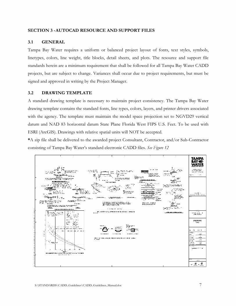
3.2 DRAWING TEMPLATE
A standard drawing template is necessary to maintain project consistency. The Tampa Bay Water
drawing template contains the standard fonts, line types, colors, layers, and printer drivers associated
with the agency. The template must maintain the model space projection set to NGVD29 vertical
datum and NAD 83 horizontal datum State Plane Florida West FIPS U.S. Feet. To be used with
ESRI (ArcGIS). Drawings with relative spatial units will NOT be accepted.
*A zip file shall be delivered to the awarded project Consultant, Contractor, and/or Sub-Contractor
consisting of Tampa Bay Water’s standard electronic CADD files. See Figure 12
S:\STANDARDS\CADD_Guidelines\CADD_Guidelines_Manual.doc 8
Figure 12
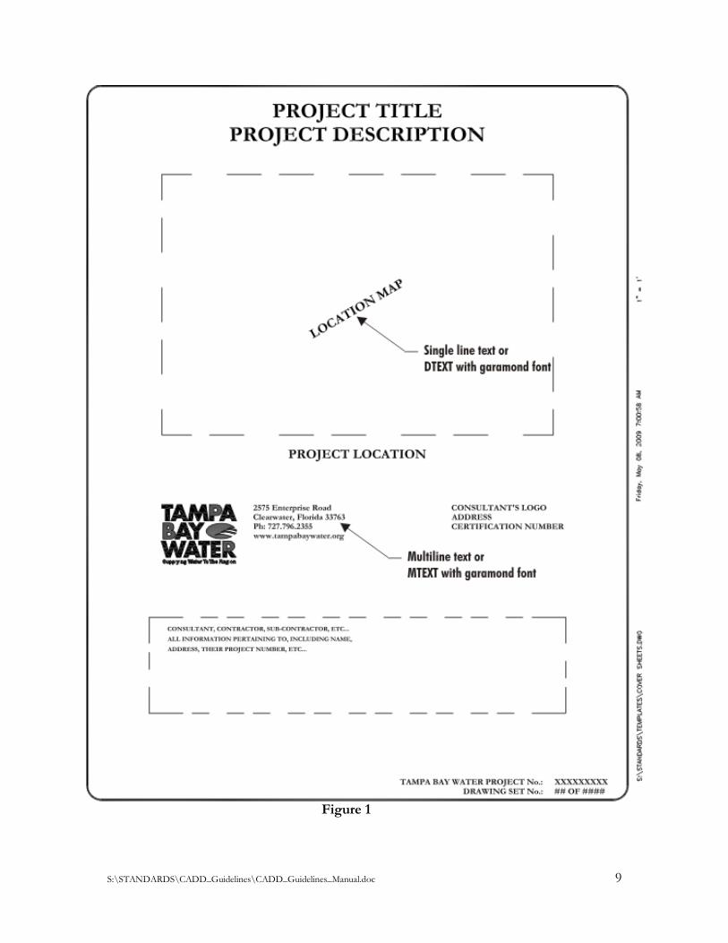
3.3 TEXT STYLE
In AutoCAD there are two different types of text, single-line and multiline text. Single-line text shall
be used for simple entries, single line labeling, leader lines, and vertical text and not used for notes,
tables, paragraphs, and labels & leader lines with multiple lines. Multiline text shall be used for long
and complex entries, notes, tables, paragraphs, and labels and leader lines with multiple lines to
maintain proper alignment, justification, and spacing. See Figure 1
3.4 FONT
There are many different prefaces of font types in addition to the different types of fonts, TrueType
fonts, SHX fonts, Adobe fonts, Mac and PC Postscript fonts, and cross platform fonts. All these
prefaces contain many groups of fonts. The font may be book, regular, heavy, bold, light, italic, bold
italic, and underlined.
For example Futura: Futura Bk BT, Futura HV BT, Futura LT BT, Futura LTCn Bt, and Futura
XBlkCnIt BT.
3.4.1 Document and Figure Sheet Fonts
Tampa Bay Water’s standard fonts are Garamond and Futura. For examples of spacing, size,
layouts, and uses of documents that are not engineering drawings, refer to the Tampa Bay
Water Identity Manual.
3.4.2 Engineering Sheet Fonts
Tampa Bay Water requires Garamond to be used in the title blocks, detail titles, and project
titles; Futura to be used for notes, labels, and dimensions. See Figures 1 and 2
S:\STANDARDS\CADD_Guidelines\CADD_Guidelines_Manual.doc 9
Figure 1

S:\STANDARDS\CADD_Guidelines\CADD_Guidelines_Manual.doc 10
Figure 2
S:\STANDARDS\CADD_Guidelines\CADD_Guidelines_Manual.doc 11
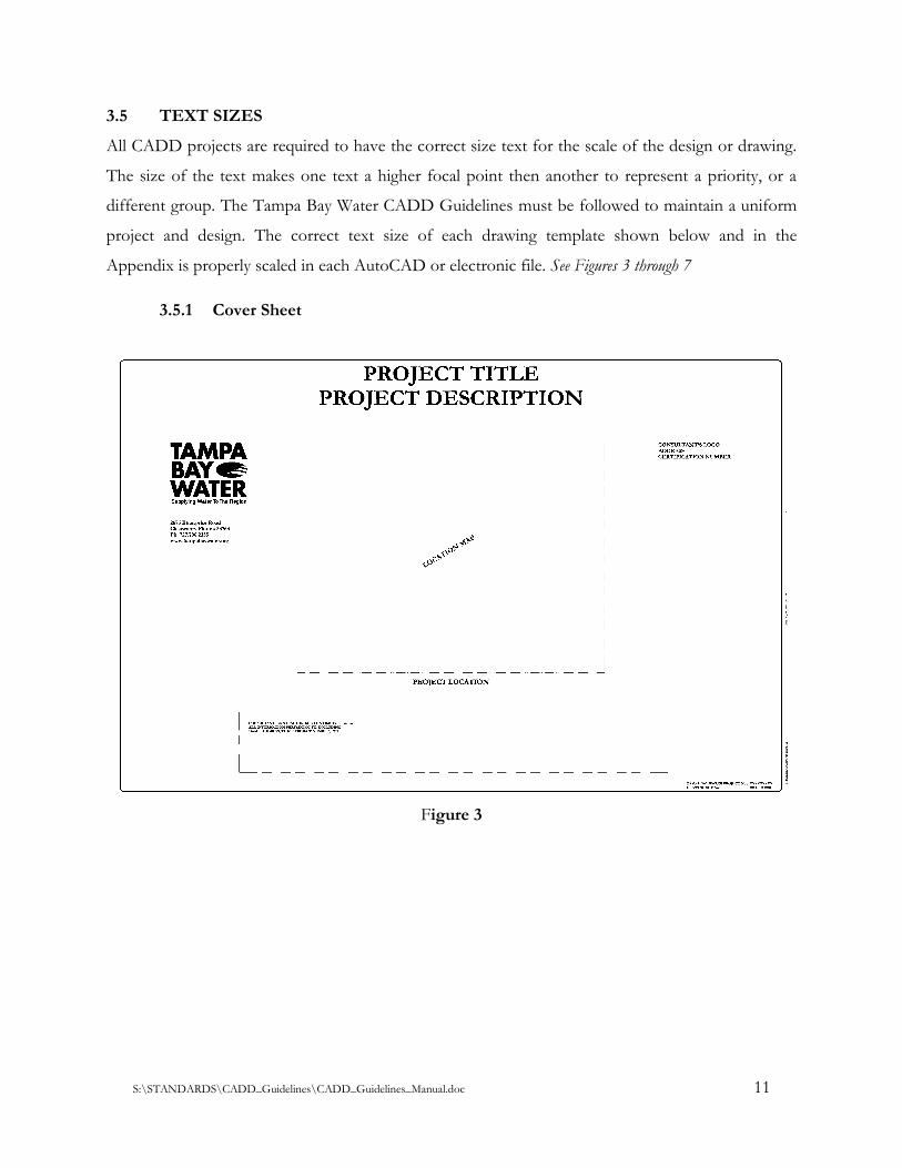
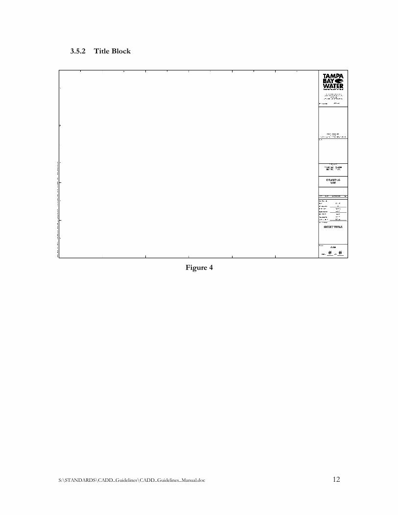
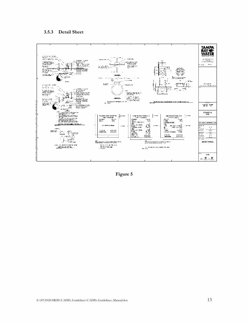
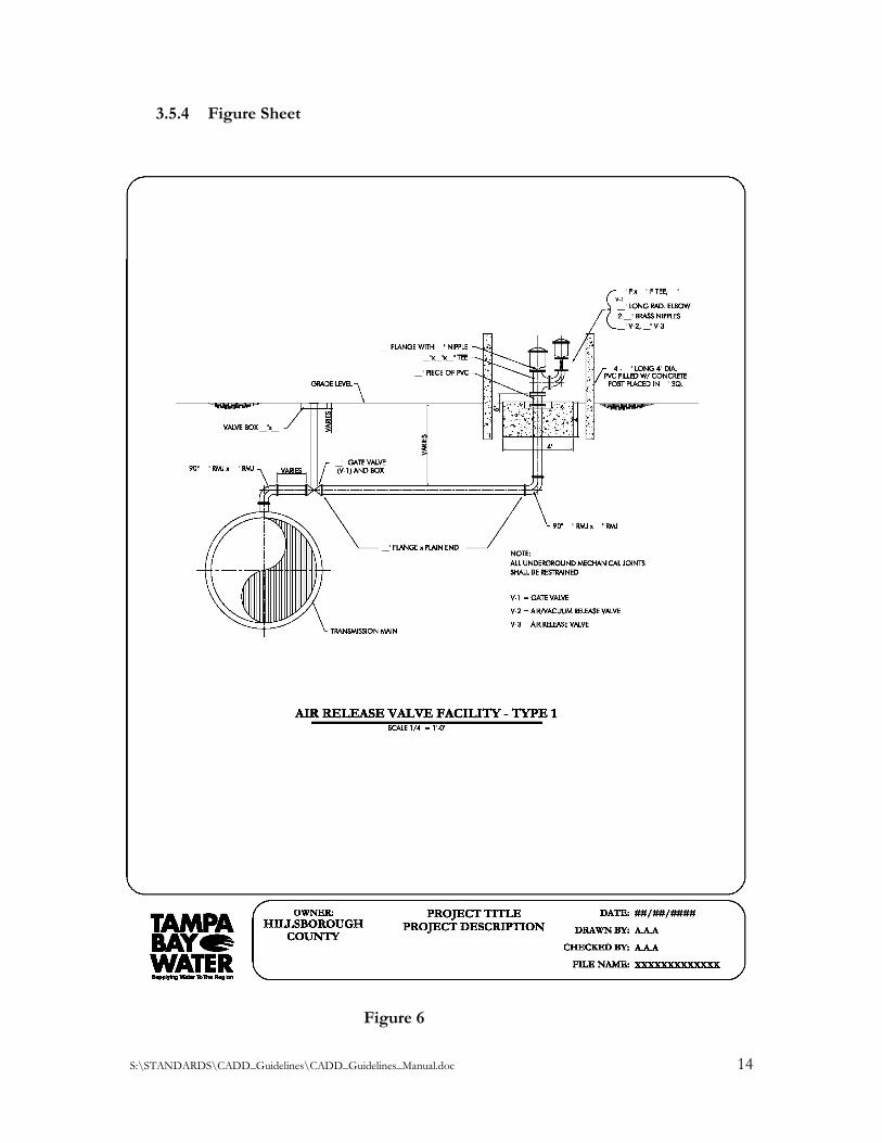
3.5 TEXT SIZES
All CADD projects are required to have the correct size text for the scale of the design or drawing.
The size of the text makes one text a higher focal point then another to represent a priority, or a
different group. The Tampa Bay Water CADD Guidelines must be followed to maintain a uniform
project and design. The correct text size of each drawing template shown below and in the
Appendix is properly scaled in each AutoCAD or electronic file. See Figures 3 through 7
3.5.1 Cover Sheet
Figure 3
S:\STANDARDS\CADD_Guidelines\CADD_Guidelines_Manual.doc 12
3.5.2 Title Block
Figure 4
S:\STANDARDS\CADD_Guidelines\CADD_Guidelines_Manual.doc 13
3.5.3 Detail Sheet
Figure 5
S:\STANDARDS\CADD_Guidelines\CADD_Guidelines_Manual.doc 14
3.5.4 Figure Sheet
Figure 6
S:\STANDARDS\CADD_Guidelines\CADD_Guidelines_Manual.doc 15
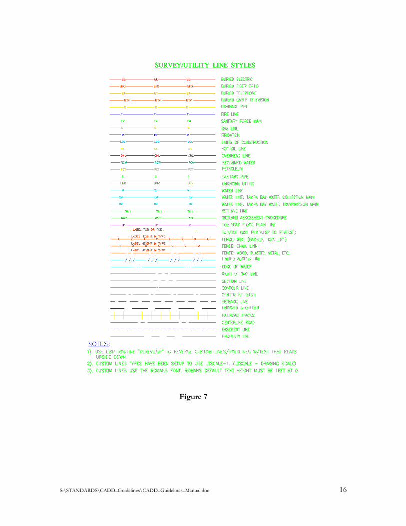
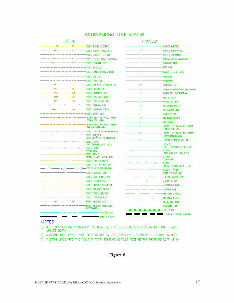
3.6 LINETYPES
A linetype is a repeating pattern of dashes, dots, and blank spaces displayed in a line or curve, used
to distinguish the difference between elements in a drawing. For example different linetypes display
graphical difference between a boundary line and power line by the different repeating design but
they can be the same color. See Figure 7 thru 8.
S:\STANDARDS\CADD_Guidelines\CADD_Guidelines_Manual.doc 16
Figure 7
S:\STANDARDS\CADD_Guidelines\CADD_Guidelines_Manual.doc 17
Figure 8
S:\STANDARDS\CADD_Guidelines\CADD_Guidelines_Manual.doc 18
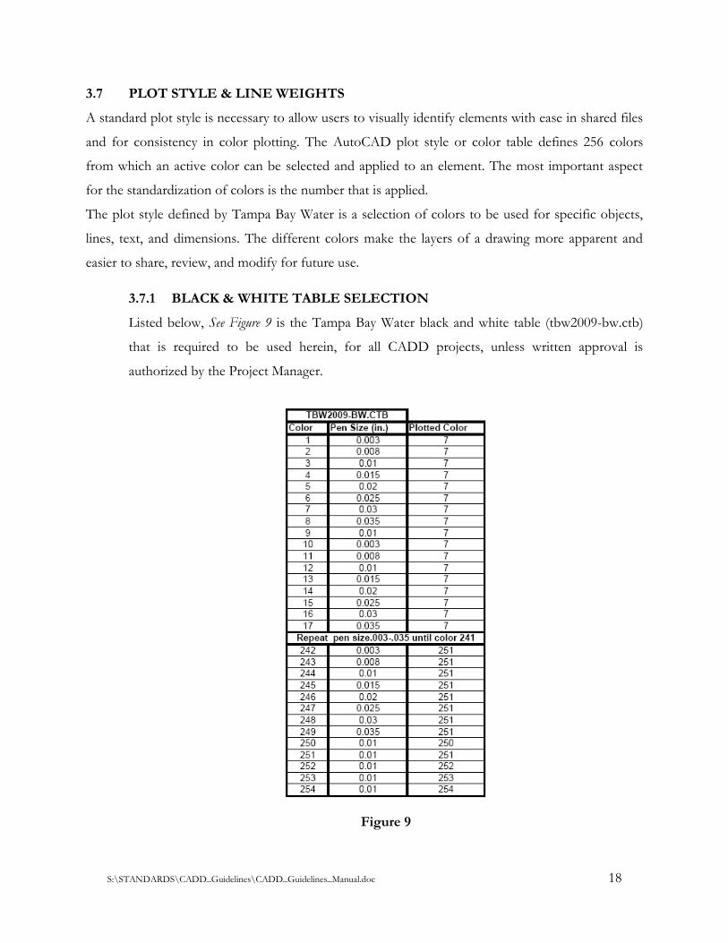
3.7 PLOT STYLE & LINE WEIGHTS
A standard plot style is necessary to allow users to visually identify elements with ease in shared files
and for consistency in color plotting. The AutoCAD plot style or color table defines 256 colors
from which an active color can be selected and applied to an element. The most important aspect
for the standardization of colors is the number that is applied.
The plot style defined by Tampa Bay Water is a selection of colors to be used for specific objects,
lines, text, and dimensions. The different colors make the layers of a drawing more apparent and
easier to share, review, and modify for future use.
3.7.1 BLACK & WHITE TABLE SELECTION
Listed below, See Figure 9 is the Tampa Bay Water black and white table (tbw2009-bw.ctb)
that is required to be used herein, for all CADD projects, unless written approval is
authorized by the Project Manager.
Figure 9
S:\STANDARDS\CADD_Guidelines\CADD_Guidelines_Manual.doc 19
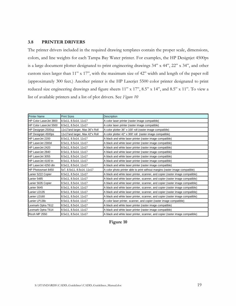
3.8 PRINTER DRIVERS
The printer drivers included in the required drawing templates contain the proper scale, dimensions,
colors, and line weights for each Tampa Bay Water printer. For examples, the HP Designjet 4500ps
is a large document plotter designated to print engineering drawings 34” x 44”, 22” x 34”, and other
custom sizes larger than 11” x 17”, with the maximum size of 42” width and length of the paper roll
(approximately 300 feet.) Another printer is the HP Laserjet 5500 color printer designated to print
reduced size engineering drawings and figure sheets 11” x 17”, 8.5” x 14”, and 8.5” x 11”. To view a
list of available printers and a list of plot drivers. See Figure 10
Printer Name Print Sizes Description
HP Color LaserJet 3800 8.5x11, 8.5x14, 11x17 A color laser printer (raster image compatible)
HP Color LaserJet 5500 8.5x11, 8.5x14, 11x17 A color laser printer (raster image compatible)
HP Designjet 2500cp 11x17and larger, Max 36"x Roll A color plotter 36" x 100' roll (raster image compatible)
HP Designjet 4500ps 11x17and larger, Max 42"x Roll A color plotter 42" x 300' roll (raster image compatible)
HP LaserJet 2200 8.5x11, 8.5x14, 11x17 A black and white laser printer (raster image compatible)
HP LaserJet 2300d 8.5x11, 8.5x14, 11x17 A black and white laser printer (raster image compatible)
HP LaserJet 2420 8.5x11, 8.5x14, 11x17 A black and white laser printer (raster image compatible)
HP LaserJet 2840 8.5x11, 8.5x14, 11x17 A black and white laser printer (raster image compatible)
HP LaserJet 3055 8.5x11, 8.5x14, 11x17 A black and white laser printer (raster image compatible)
HP LaserJet 4100 tn 8.5x11, 8.5x14, 11x17 A black and white laser printer (raster image compatible)
HP LaserJet 4250 dtn 8.5x11, 8.5x14, 11x17 A black and white laser printer (raster image compatible)
HP Photosmart 8450 5x7, 8.5x11, 8.5x14, 11x17 A color photo printer able to print without margins (raster image compatible)
Lanier 5222 Copier 8.5x11, 8.5x14, 11x17 A black and white laser printer, scanner, and copier (raster image compatible)
Lanier 5485 8.5x11, 8.5x14, 11x17 A black and white laser printer, scanner, and copier (raster image compatible)
Lanier 5635 Copier 8.5x11, 8.5x14, 11x17 A black and white laser printer, scanner, and copier (raster image compatible)
Lanier 5645 8.5x11, 8.5x14, 11x17 A black and white laser printer, scanner, and copier (raster image compatible)
Lanier LD135 8.5x11, 8.5x14, 11x17 A black and white laser printer, scanner, and copier (raster image compatible)
Lanier LD160 8.5x11, 8.5x14, 11x17 A black and white laser printer, scanner, and copier (raster image compatible)
Lanier LP138c 8.5x11, 8.5x14, 11x17 A color laser printer, scanner, and copier (raster image compatible)
Lexmark Optra T612 8.5x11, 8.5x14, 11x17 A black and white laser printer (raster image compatible)
Lexmark Optra T614 8.5x11, 8.5x14, 11x17 A black and white laser printer (raster image compatible)
Ricoh MP 2550 8.5x11, 8.5x14, 11x17 A black and white laser printer, scanner, and copier (raster image compatible)
Figure 10
S:\STANDARDS\CADD_Guidelines\CADD_Guidelines_Manual.doc 20
SECTION 4 - DIRECTORY STRUCTURE
4.1 GENERAL
Many projects are designed, built, and referenced over a long period of time and must stay
organized. To maintain organization, each project must have its own project number and name
placed in a directory system with files and folders. Projects may have the same or similar names,
causing confusion and poor management. To resolve this issue a unique alphanumeric character
system assigned to each file was created and must be followed.
4.2 DATA DIRECTORY STRUCTURE
The engineering drawing files shall be organized and maintained in a standard file directory
structure. The file folder shall be spelled without any spaces, requiring the use of underline spaces
and/or dashes between numbers, words, and names. The reason for no spacing is due to programs
creating %% for every space between a character in a directory or name. The discipline of sub-
directory folders and files varies between Project Managers, and must meet the Project Manager’s
requirements.
4.2.1 PROJECT DATA DIRECTORY STRUCTURE
The project engineering drawing files shall be organized in a standard file directory structure.
The project folders are required to be established in a hierarchy structure with the project
name as the primary or parent folder. Then the project number as the first sub-folder or
child, followed by the Project Manager’s directory structure requirements.
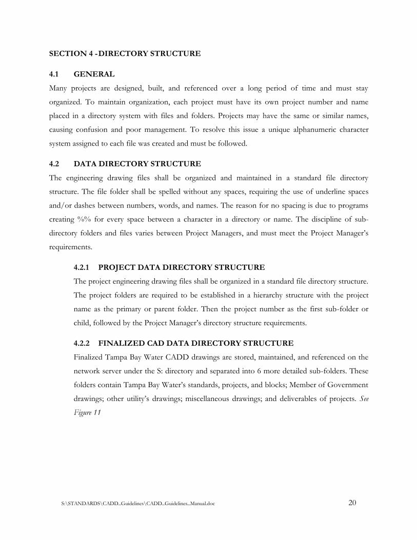
4.2.2 FINALIZED CAD DATA DIRECTORY STRUCTURE
Finalized Tampa Bay Water CADD drawings are stored, maintained, and referenced on the
network server under the S: directory and separated into 6 more detailed sub-folders. These
folders contain Tampa Bay Water’s standards, projects, and blocks; Member of Government
drawings; other utility’s drawings; miscellaneous drawings; and deliverables of projects. See
Figure 11
S:\STANDARDS\CADD_Guidelines\CADD_Guidelines_Manual.doc 21
Figure 11
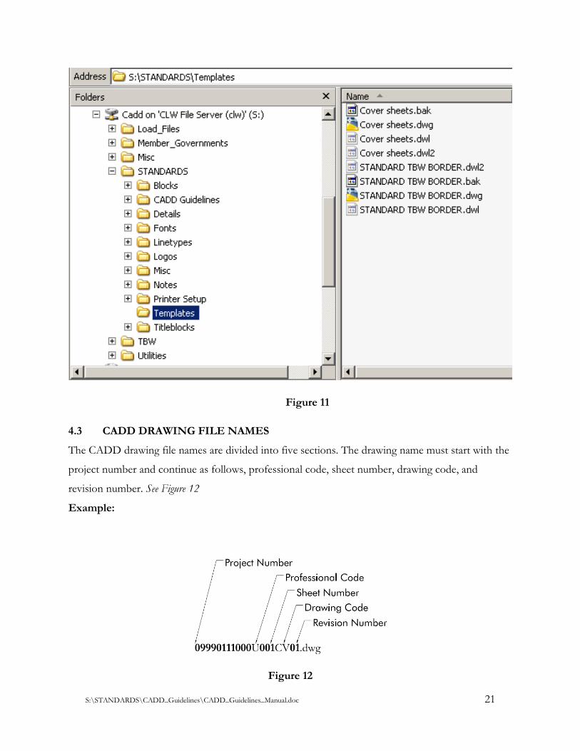
4.3 CADD DRAWING FILE NAMES
The CADD drawing file names are divided into five sections. The drawing name must start with the
project number and continue as follows, professional code, sheet number, drawing code, and
revision number. See Figure 12
Example:
Figure 12
S:\STANDARDS\CADD_Guidelines\CADD_Guidelines_Manual.doc 22
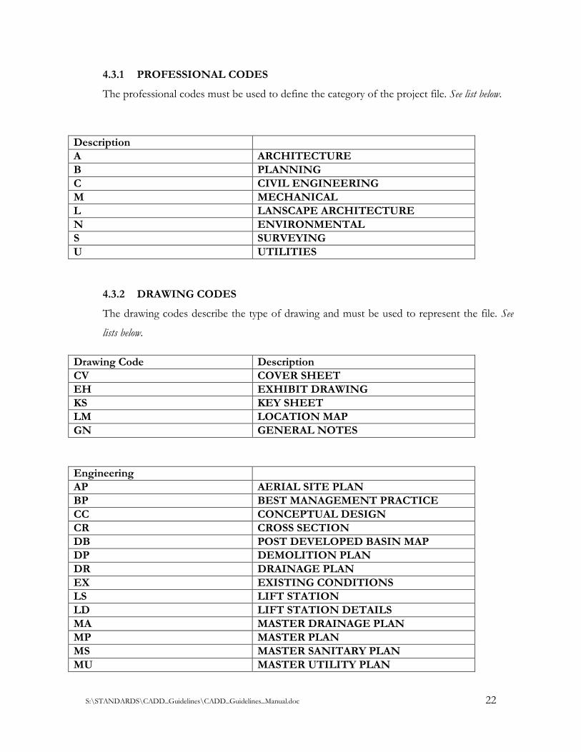
4.3.1 PROFESSIONAL CODES
The professional codes must be used to define the category of the project file. See list below.
Description
A ARCHITECTURE
B PLANNING
C CIVIL ENGINEERING
M MECHANICAL
L LANSCAPE ARCHITECTURE
N ENVIRONMENTAL
S SURVEYING
U UTILITIES
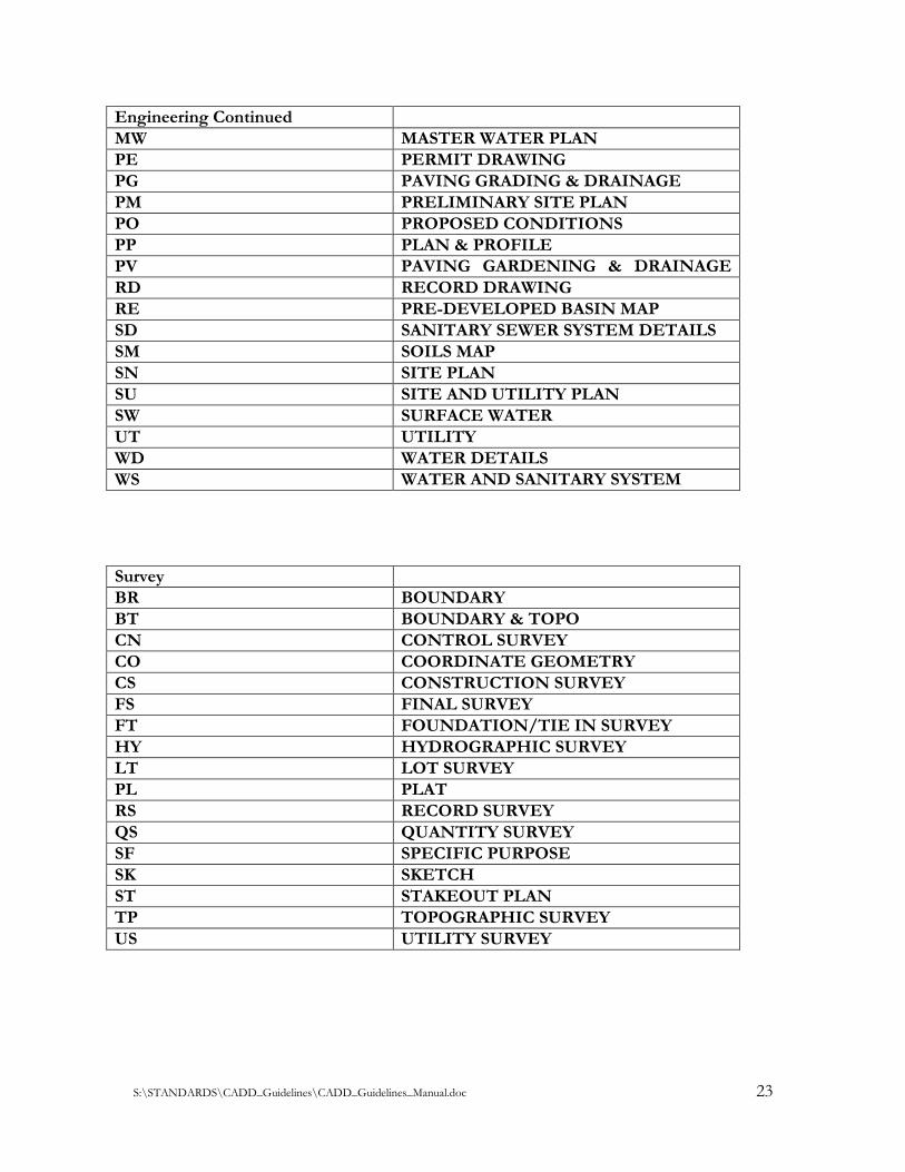
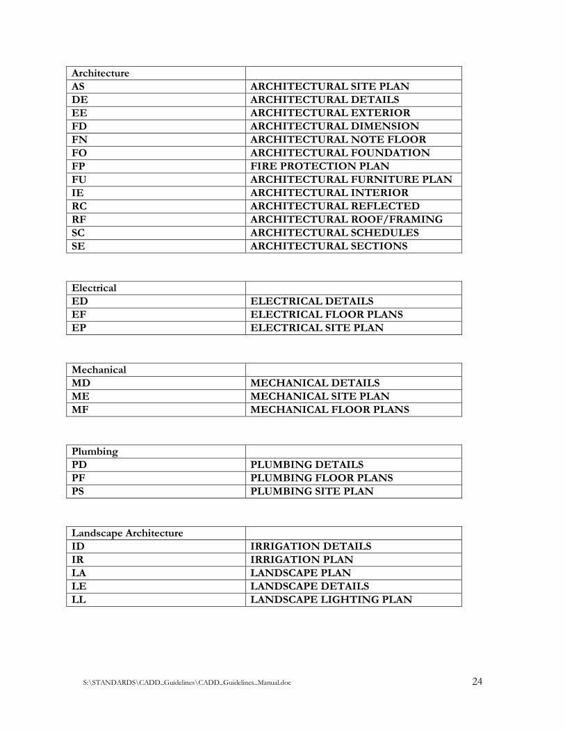
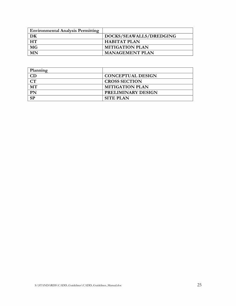
4.3.2 DRAWING CODES
The drawing codes describe the type of drawing and must be used to represent the file. See
lists below.
Drawing Code Description
CV COVER SHEET
EH EXHIBIT DRAWING
KS KEY SHEET
LM LOCATION MAP
GN GENERAL NOTES
Engineering
AP AERIAL SITE PLAN
BP BEST MANAGEMENT PRACTICE
CC CONCEPTUAL DESIGN
CR CROSS SECTION
DB POST DEVELOPED BASIN MAP
DP DEMOLITION PLAN
DR DRAINAGE PLAN
EX EXISTING CONDITIONS
LS LIFT STATION
LD LIFT STATION DETAILS
MA MASTER DRAINAGE PLAN
MP MASTER PLAN
MS MASTER SANITARY PLAN
MU MASTER UTILITY PLAN
S:\STANDARDS\CADD_Guidelines\CADD_Guidelines_Manual.doc 23
Engineering Continued
MW MASTER WATER PLAN
PE
PG
PERMIT DRAWING
PG PAVING GRADING & DRAINAGE
PM PRELIMINARY SITE PLAN
PO PROPOSED CONDITIONS
PP PLAN & PROFILE
PV PAVING GARDENING & DRAINAGE
DETAILS RD RECORD DRAWING
RE PRE-DEVELOPED BASIN MAP
SD SANITARY SEWER SYSTEM DETAILS
SM
SP
SOILS MAP
SN SITE PLAN
SU SITE AND UTILITY PLAN
SW SURFACE WATER
UT UTILITY
WD WATER DETAILS
WS WATER AND SANITARY SYSTEM
PLAN
Survey
BR BOUNDARY
BT BOUNDARY & TOPO
CN CONTROL SURVEY
CO COORDINATE GEOMETRY
CS CONSTRUCTION SURVEY
FS FINAL SURVEY
FT FOUNDATION/TIE IN SURVEY
HY HYDROGRAPHIC SURVEY
LT LOT SURVEY
PL PLAT
RS RECORD SURVEY
QS QUANTITY SURVEY
SF SPECIFIC PURPOSE
SK SKETCH
ST STAKEOUT PLAN
TP TOPOGRAPHIC SURVEY
US UTILITY SURVEY
S:\STANDARDS\CADD_Guidelines\CADD_Guidelines_Manual.doc 24
Architecture
AS ARCHITECTURAL SITE PLAN
DE ARCHITECTURAL DETAILS
EE ARCHITECTURAL EXTERIOR
ELEVATIONS FD ARCHITECTURAL DIMENSION
FLOOR PLAN FN ARCHITECTURAL NOTE FLOOR
PLAN FO ARCHITECTURAL FOUNDATION
PLAN FP FIRE PROTECTION PLAN
FU ARCHITECTURAL FURNITURE PLAN
IE ARCHITECTURAL INTERIOR
ELEVATIONS RC ARCHITECTURAL REFLECTED
CEILING PLAN RF ARCHITECTURAL ROOF/FRAMING
PLAN SC ARCHITECTURAL SCHEDULES
SE ARCHITECTURAL SECTIONS
Electrical
ED ELECTRICAL DETAILS
EF ELECTRICAL FLOOR PLANS
EP ELECTRICAL SITE PLAN
Mechanical
MD MECHANICAL DETAILS
ME MECHANICAL SITE PLAN
MF MECHANICAL FLOOR PLANS
Plumbing
PD PLUMBING DETAILS
PF PLUMBING FLOOR PLANS
PS PLUMBING SITE PLAN
Landscape Architecture
ID IRRIGATION DETAILS
IR IRRIGATION PLAN
LA LANDSCAPE PLAN
LE LANDSCAPE DETAILS
LL LANDSCAPE LIGHTING PLAN
S:\STANDARDS\CADD_Guidelines\CADD_Guidelines_Manual.doc 25
Environmental Analysis Permitting
DK DOCKS/SEAWALLS/DREDGING
HT HABITAT PLAN
MG MITIGATION PLAN
MN MANAGEMENT PLAN
Planning
CD CONCEPTUAL DESIGN
CT CROSS SECTION
MT MITIGATION PLAN
PN PRELIMINARY DESIGN
SP SITE PLAN
S:\STANDARDS\CADD_Guidelines\CADD_Guidelines_Manual.doc 26
SECTION 5 - FILE LAYER STANDARDS
5.1 GENERAL
Layers are the foundation of an engineering drawing and its uses. This section will describe how
layers functions and shall be used. Layering a drawing can manipulate the drawing and make it
appear different, and can create structure for a design. Layers allow different objects to be selected,
become visible, invisible, printed, exported, grouped etc.
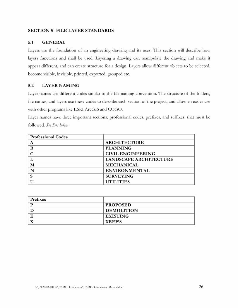
5.2 LAYER NAMING
Layer names use different codes similar to the file naming convention. The structure of the folders,
file names, and layers use these codes to describe each section of the project, and allow an easier use
with other programs like ESRI ArcGIS and COGO.
Layer names have three important sections; professional codes, prefixes, and suffixes, that must be
followed. See lists below
Professional Codes
A ARCHITECTURE
B PLANNING
C CIVIL ENGINEERING
L LANDSCAPE ARCHITECTURE
M MECHANICAL
N ENVIRONMENTAL
S SURVEYING
U UTILITIES
Prefixes
P PROPOSED
D DEMOLITION
E EXISTING
X XREF’S
S:\STANDARDS\CADD_Guidelines\CADD_Guidelines_Manual.doc 27
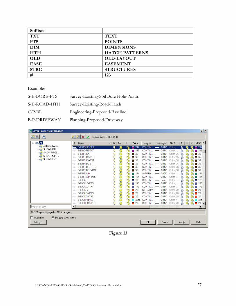
Suffixes
TXT TEXT
PTS POINTS
DIM DIMENSIONS
HTH HATCH PATTERNS
OLD OLD-LAYOUT
EASE EASEMENT
STRC STRUCTURES
# 123
Examples:
S-E-BORE-PTS Survey-Existing-Soil Bore Hole-Points
S-E-ROAD-HTH Survey-Existing-Road-Hatch
C-P-BL Engineering-Proposed-Baseline
B-P-DRIVEWAY Planning-Proposed-Driveway
Figure 13
S:\STANDARDS\CADD_Guidelines\CADD_Guidelines_Manual.doc 28
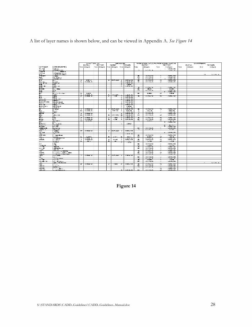
A list of layer names is shown below, and can be viewed in Appendix A. See Figure 14
Figure 14
S:\STANDARDS\CADD_Guidelines\CADD_Guidelines_Manual.doc 29
SECTION 6 - PROJECT DELIVERY PROCEEDURES
6.1 GENERAL
This section addresses engineering drawings that are required to be delivered to Tampa Bay Water
prior to a project’s final acceptance. The drawings (.dwg) shall be reviewed and commented by the
Engineer and Tampa Bay Water staff, to meet the requirements in the CADD Guidelines Manual.
6.2 PROJECT DOCUMENTS DELIVERED
Electronic formats and templates of fonts, title blocks, line types, and line weights shall be delivered
by Tampa Bay Water to the Contractor, as a standards package prior to the beginning of a project,
that must be followed and applied, throughout the project engineering drawings. The engineering
drawings shall be delivered by the Contractor to Tampa Bay Water with all fonts, title blocks, X-ref.
files, and blocks to complete the .dwg files and meet final acceptance.
6.2.1 STANDARD AUTOCAD ENGINEERING DRAWINGS DELIVERED
Three paper 22” x 34” size sets of drawings, or other size stated by Tampa Bay Water
(OWNER), each signed and sealed by the Engineer(s) of Record, shall be delivered to the
OWNER. In addition, one electronic file of each drawing in Win. OS - AutoCAD 2010
format shall be provided to the OWNER in the most logical format listed by judging the size
of the project. The formats are CD, DVD, Blu-Ray DVD, Flash Cards or memory sticks,
USB Drive, and/or portable Hard Drive.
6.2.2 RETURNED ENGINEERING DRAWINGS
It is the responsibility of the Contractor to review and confirm the engineering drawings
meet Tampa Bay Water’s CADD Guidelines Manual. After the project engineering drawings
are delivered to Tampa Bay Water, the drawing shall be reviewed by Tampa Bay Water staff
for approval. If the drawings do not meet Tampa Bay Water’s CADD Guidelines Manual,
the drawing shall be commented with corrections in writing, and sent back to the Contractor
to be corrected and redelivered to Tampa Bay Water at the Contractor’s expense.
S:\STANDARDS\CADD_Guidelines\CADD_Guidelines_Manual.doc 30
SECTION 7 - DEFINITIONS AND FILE FORMATS
7.1 DEFINITIONS
The AutoCAD definitions described below are listed to serve as a quick reference, and allow users
to better understand CADD terminology.
ANSI (American National Standards Institute) – Coordinator of voluntary standards
development for both private and public sectors in the United States. Standards pertain
to programming languages, Electronic Data Interchange (EDI), telecommunications,
and the physical properties of diskettes, cartridges, and magnetic tapes.
Block – A generic term for one or more objects that are combined to create a single
object. Commonly used for either block definition or block reference. (Block definition – The
name, base point, and set of objects that are combined and stored in the symbol table of
a drawing.
CADD (Computer Aided Design and Drafting) – A Software and methods used to
analyze and represent designs graphically.
CADD Hardware – The workstations, servers, printers, plotters and all other computer
equipment used in Tampa Bay Water’s production effort.
CMYK (Cyan, Magenta, Yellow, and Key Color) – A system of defining colors by
specifying the percentages of cyan, magenta, yellow, and the key color, which is typically
black. (typically used in printing devices)
Electronic Project – All electronic files, reports, documents, databases, images and
other electronic information representing a complete contract document package for a
Department construction project. Sometimes called a CADD project.
Engineering Data – The digital files which support or represent the intent of the
engineering design, or the engineering analysis.
Font – A character set, comprising letters, numbers, punctuation marks, and symbols of
a distinctive proportion and design.
S:\STANDARDS\CADD_Guidelines\CADD_Guidelines_Manual.doc 31
Freeze – A setting that suppresses the display of an object on selected layers. Objects on
frozen layers are not displayed, regenerated, or plotted. Freezing layers shortens
regenerating time.
Geometry – All graphical objects such as lines, circles, arcs, polylines, and dimensions.
Nongraphical objects, such as linetypes, lineweights, text styles, and layers are not
considered geometry.
CADD Software – Any software procured, developed, distributed and supported by IS
Support.
CADD Support – The technical and operational support necessary to ensure that a
production environment is maintained within Tampa Bay Water, which includes: (a)
Selection, development and distribution of production software, related procedures,
criteria and standard operating instructions, (b) Providing training opportunities to
CADD users. (c) Managing engineering data produced with the software.
CADD Server – A computer dedicated to the management of Tampa Bay Water’s
Engineering / CADD applications.
CADD Systems – All of the CADD hardware and CADD software that support the
CADD production effort.
CADD Workstation – A computer running CADD software used for the development
of CADD drawings and documents.
Layer – A logical grouping of data that are like transparent acetate overlays on a
drawing. You can view layers individually of in combination.
Leader Line Text – A leader object is a line or spline with an arrowhead at one end and
a multiline text object at the other.
Linetypes – How a line of type of curve is displayed. For example, a continuous line has
a different linetype than a dashed line. Also called line font.
Lineweight – A width value that can be assigned to all graphical objects except
S:\STANDARDS\CADD_Guidelines\CADD_Guidelines_Manual.doc 32
TrueType fonts and raster images.
Multiline Text – MTEXT command to create one or more paragraphs of text that can
be modified as a single object.
Object – One or more graphical elements, such as text, dimensions, lines, circles, or
polylines, treated as a single element for creation, manipulation, and modification.
Plot Style – An object property that specifies a set of overrides for color, dithering, gray
scale, pen assignments, screening, linetype, lineweight, endstyles, joinstyles, and fill styles.
Plot styles are applied at plot time.
Reference – A definition, known as an external reference or block reference, that is
used and stored in the drawing. See also block (block) and external reference(xref)
RGB (Red, Green, and Blue) – A system of defining colors by specifying percentages
of red, green, and blue. (typically used in lighting devices)
Single-Line Text – The TEXT command to create one or more lines of text, ending
each line with an ENTER command. Each text line is an independent object that can be
rotated, reformed, or otherwise modified.
Substitute Font – If a font is not currently on your system, AutoCAD accommodates
that font by substituting it with another font.
Symbol – A representation of an item commonly used in drawings. In AutoCAD
symbols are inserted in drawings as blocks.
Template Drawing – Drawing file with preestablished settings for new drawings such
as acad.dwt and acadiso.dwt; however, any drawing can be used as a template.
Text Style – A named, saved collection of settings that determines the appearance of
text characters-for example, stretched, compressed, oblique, mirrored, or set in a vertical
column.
Tilemode – A system variable that controls whether viewports can be created as
S:\STANDARDS\CADD_Guidelines\CADD_Guidelines_Manual.doc 33
movable, resizable objects (layout viewports), or as non-overlapping display elements
that appear side-by-side (model viewports.) See also viewport.
Viewport – A bounded area that displays some portion of the model space of a drawing.
The TILEMODE system variable determines the type of viewport created.
World Coordinate System (WCS) – A coordinate system used as the basis for defining
all objects and other coordinate systems.
7.2 FILE FORMATS
*.PLT (Plot) – File format used by applications to print 2D drawings.
*.PS (PostScript) – PostScript is primarily designed to present publication-quality text.
A PostScript file consists of a set of images of pages.
*.XML (Extensible Markup Language) – A general-purpose specification for
creating custom markup languages.
*.RPT (Report) – An Output file, or report, created by Crystal Reports reporting
software; can include data from multiple data sources and many different types of
databases.
7.3 AUTOCAD FORMATS
The AutoCAD formats describe each abbreviation and the section of AutoCAD it affects.
*.CTB (Custody Toolbox Data) – A file format is an AutoCAD color-dependent plot
style table. Plot style tables contain user-defined plot styles.
*.DSD (Drawing Set Descriptions) – A file format for saving a description of a
drawing set that has been assembled using the Published dialog box.
*.DST (Sheet Set Data) – The XML file format used to store the associations and
information that define a sheet set.
*.DWF (Design Web Format) – A highly compressed file format that is created from a
DWG file. DWF files are easy to published and view on the web.
S:\STANDARDS\CADD_Guidelines\CADD_Guidelines_Manual.doc 34
*.DWG (Drawing) – Standard file format for saving vector graphics from within
AutoCAD.
*.DXF (Drawing Interchange Format) – An ASCII or binary file format of an
AutoCAD drawing file for exporting AutoCAD drawings to other applications or for
importing drawings from other applications.
7.4 MICROSTATION FORMATS
The MicroStation formats describe each abbreviation and the section of MicroStation it affects.
*.CEL (Cell) – A complex element composed of a group of primary elements or other
complex elements. Cells are stored in a cell library.
*.DGN (Design) – The standard file format for saving vector graphics or CAD designs
from within Bentley Systems, MicroStation.
*.RSC (Resource) – The resource file format for font in MicroStation
*.TBL (Table) – The color palettes created in MicroStation for an elements print size
and color.
S:\STANDARDS\CADD_Guidelines\CADD_Guidelines_Manual.doc 35
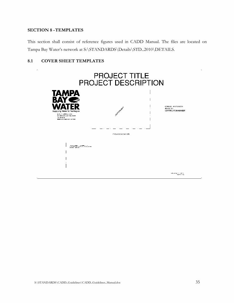
SECTION 8 - TEMPLATES
This section shall consist of reference figures used in CADD Manual. The files are located on
Tampa Bay Water’s network at S:\STANDARDS\Details\STD_2010\DETAILS.
8.1 COVER SHEET TEMPLATES
S:\STANDARDS\CADD_Guidelines\CADD_Guidelines_Manual.doc 36
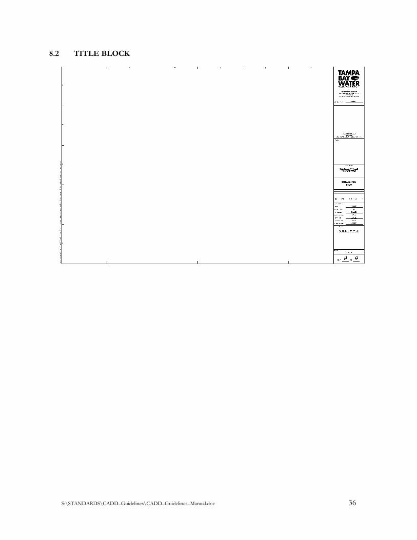
8.2 TITLE BLOCK
S:\STANDARDS\CADD_Guidelines\CADD_Guidelines_Manual.doc 37
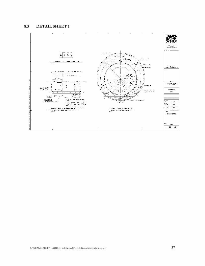
8.3 DETAIL SHEET 1
S:\STANDARDS\CADD_Guidelines\CADD_Guidelines_Manual.doc 38
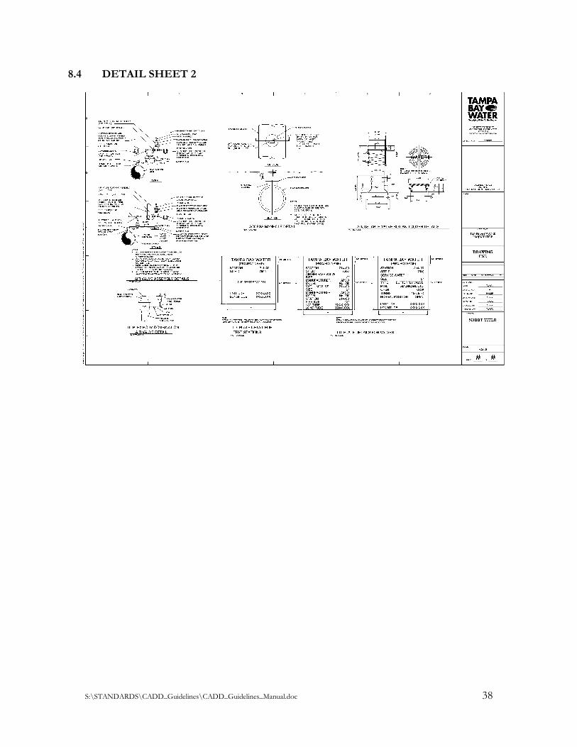
8.4 DETAIL SHEET 2
S:\STANDARDS\CADD_Guidelines\CADD_Guidelines_Manual.doc 39
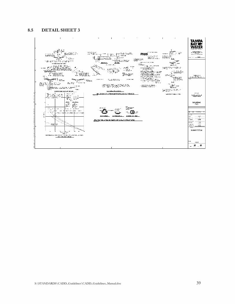
8.5 DETAIL SHEET 3
S:\STANDARDS\CADD_Guidelines\CADD_Guidelines_Manual.doc 40
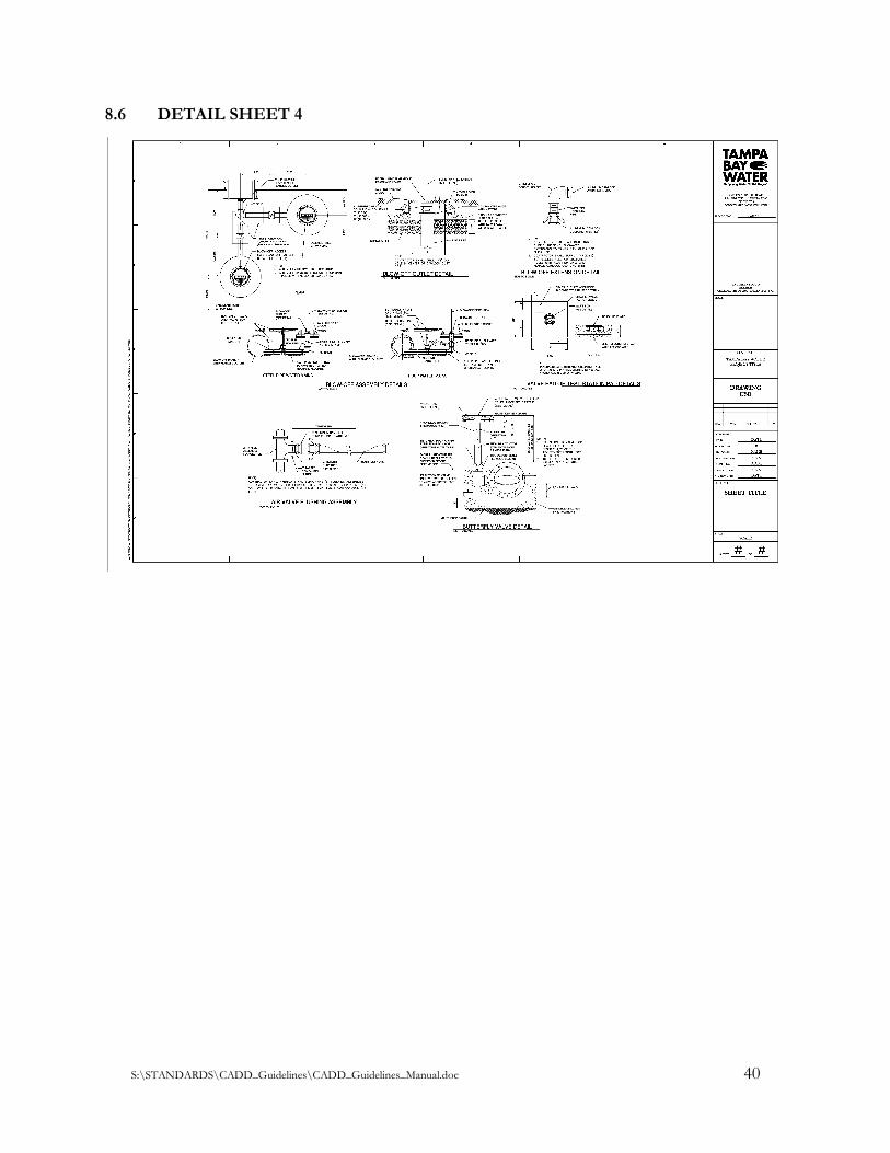
8.6 DETAIL SHEET 4
S:\STANDARDS\CADD_Guidelines\CADD_Guidelines_Manual.doc 41
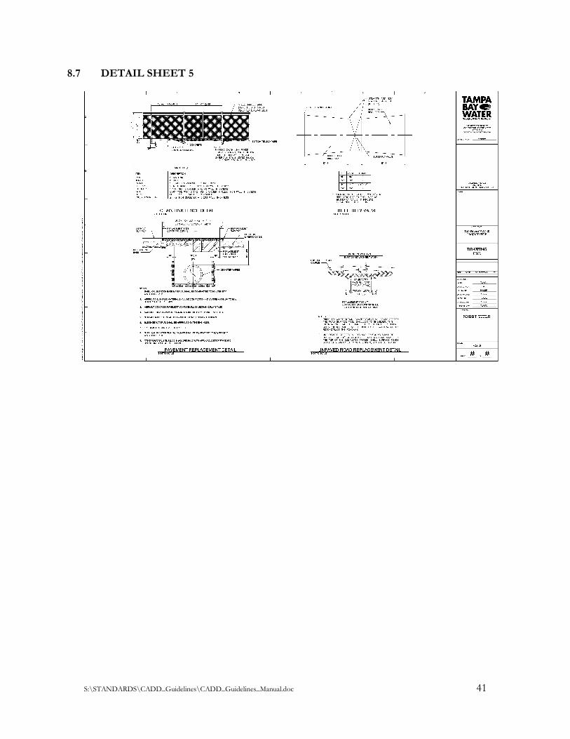
8.7 DETAIL SHEET 5
S:\STANDARDS\CADD_Guidelines\CADD_Guidelines_Manual.doc 42
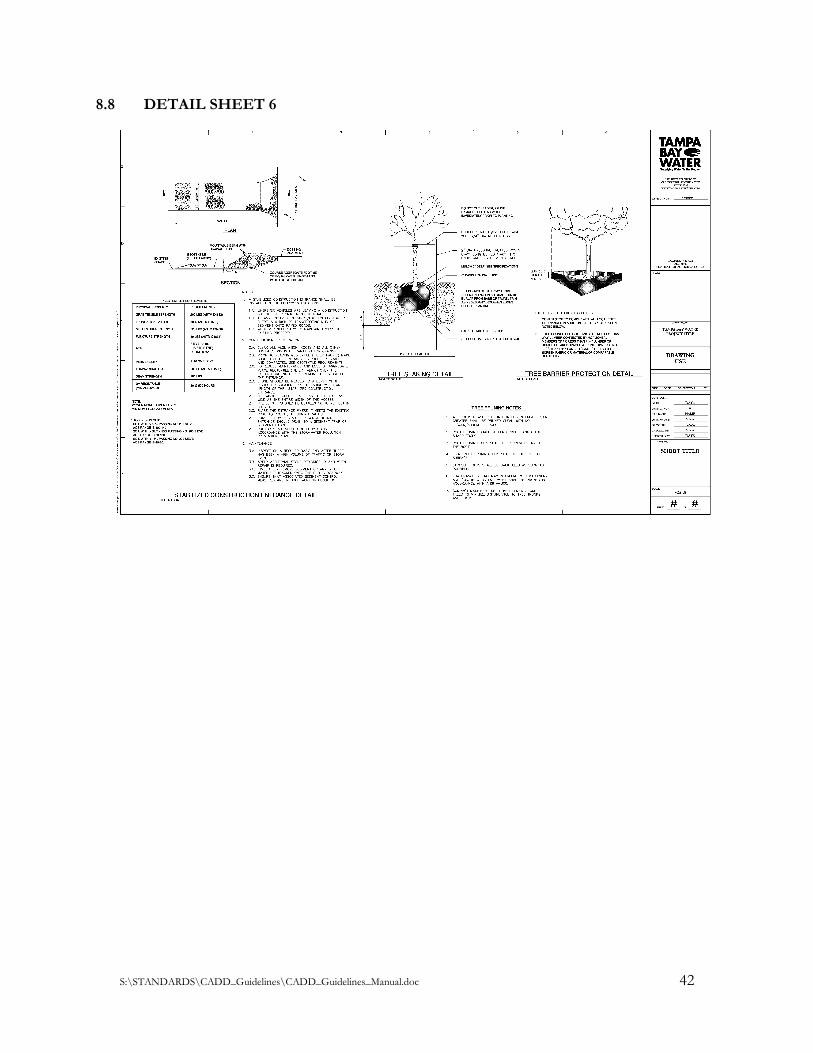
8.8 DETAIL SHEET 6
S:\STANDARDS\CADD_Guidelines\CADD_Guidelines_Manual.doc 43
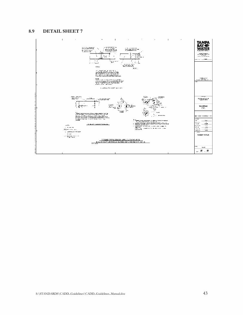
8.9 DETAIL SHEET 7