CAD/CAM/CAE Computer Aided Design/Computer …CAD/CAM/CAE Computer Aided Design/Computer Aided...
32
CAD/CAM/CAE Computer Aided Design/Computer Aided Manufacturing/Computer Aided Manufacturing Part-9 CNC Fundamentals
Transcript of CAD/CAM/CAE Computer Aided Design/Computer …CAD/CAM/CAE Computer Aided Design/Computer Aided...
CAD/CAM/CAEComputer Aided Design/Computer Aided
Manufacturing/Computer Aided Manufacturing
Part-9CNC Fundamentals
CNC Fundamentals
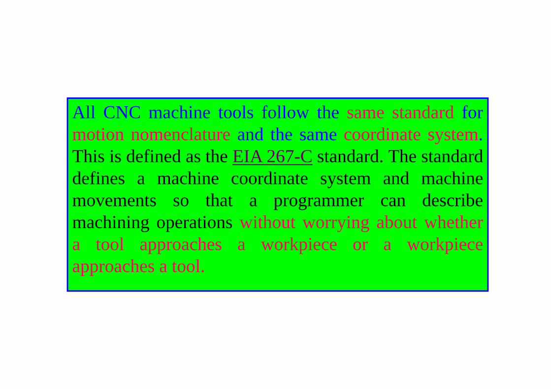
All CNC machine tools follow the same standard formotion nomenclature and the same coordinate system.This is defined as the EIA 267-C standard. The standarddefines a machine coordinate system and machinemovements so that a programmer can describemachining operations without worrying about whethera tool approaches a workpiece or a workpieceapproaches a tool.
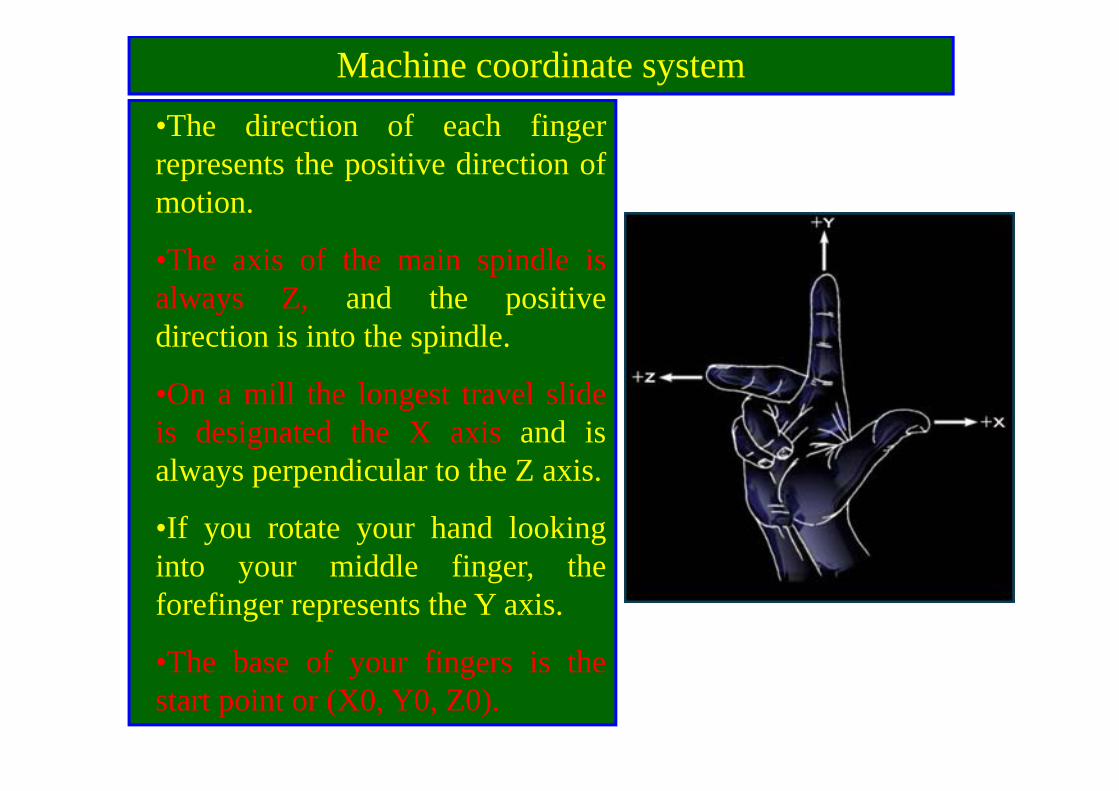
Machine coordinate system•The direction of each fingerrepresents the positive direction ofmotion.
•The axis of the main spindle isalways Z, and the positivedirection is into the spindle.
•On a mill the longest travel slideis designated the X axis and isalways perpendicular to the Z axis.
•If you rotate your hand lookinginto your middle finger, theforefinger represents the Y axis.
•The base of your fingers is thestart point or (X0, Y0, Z0).
Axis and motion nomenclature – Rotary motion designation
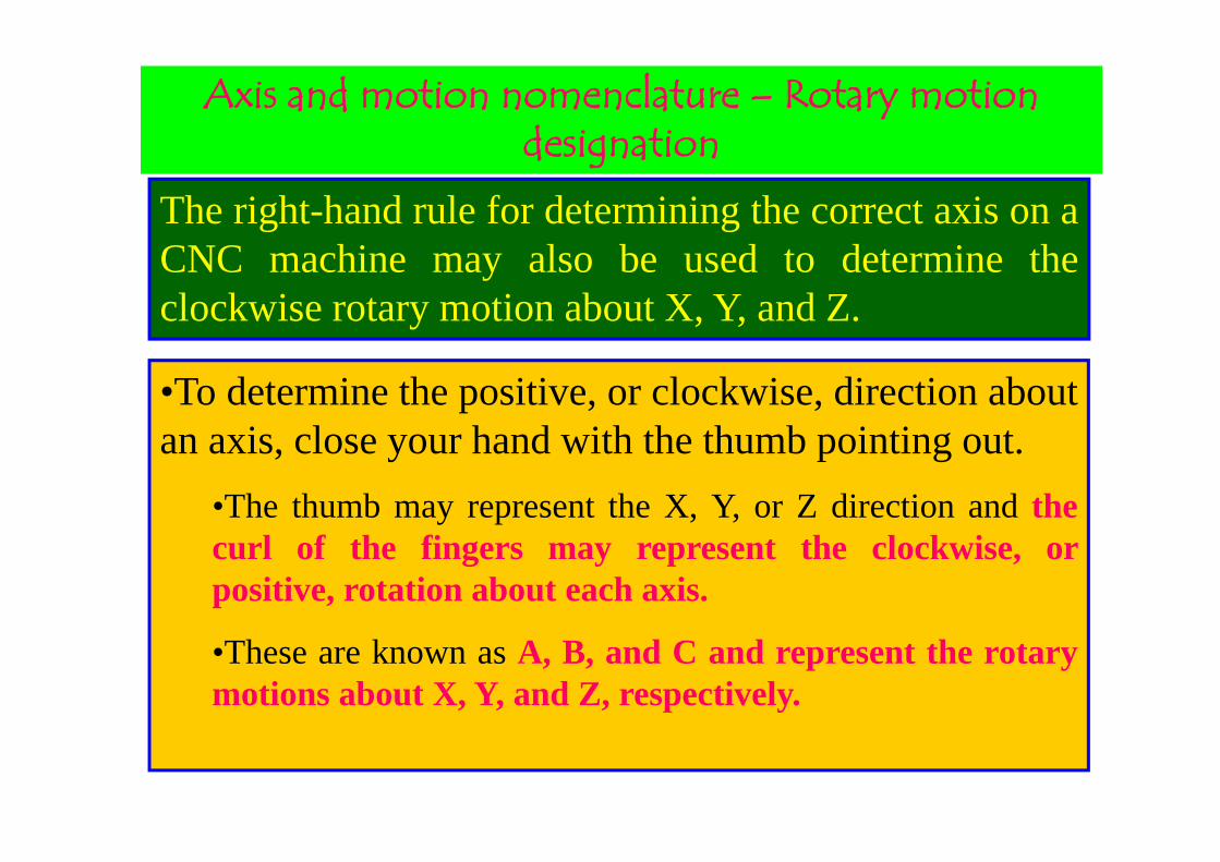
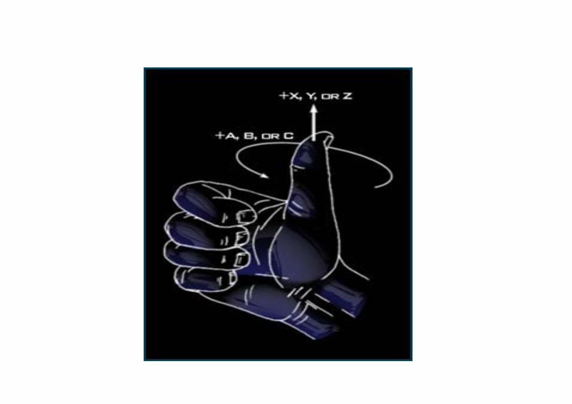
The right-hand rule for determining the correct axis on aCNC machine may also be used to determine theclockwise rotary motion about X, Y, and Z.
•To determine the positive, or clockwise, direction aboutan axis, close your hand with the thumb pointing out.
•The thumb may represent the X, Y, or Z direction and thecurl of the fingers may represent the clockwise, orpositive, rotation about each axis.
•These are known as A, B, and C and represent the rotarymotions about X, Y, and Z, respectively.

Axis and motion nomenclature – CNC mill
On this gantry mill the spindle travels along the X Axis. Thetravel direction of the table designates the Y Axis. The Z Axis isdesignated by the stationary vertical column.
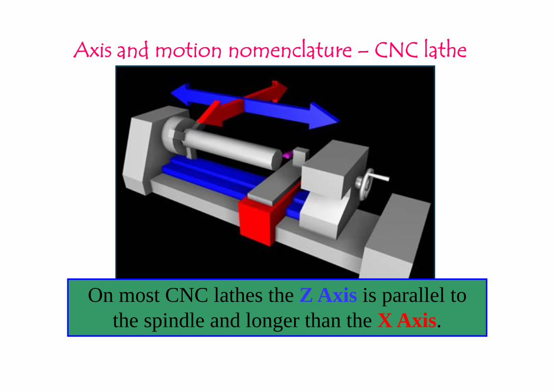
Axis and motion nomenclature – CNC lathe
On most CNC lathes the Z Axis is parallel to the spindle and longer than the X Axis.
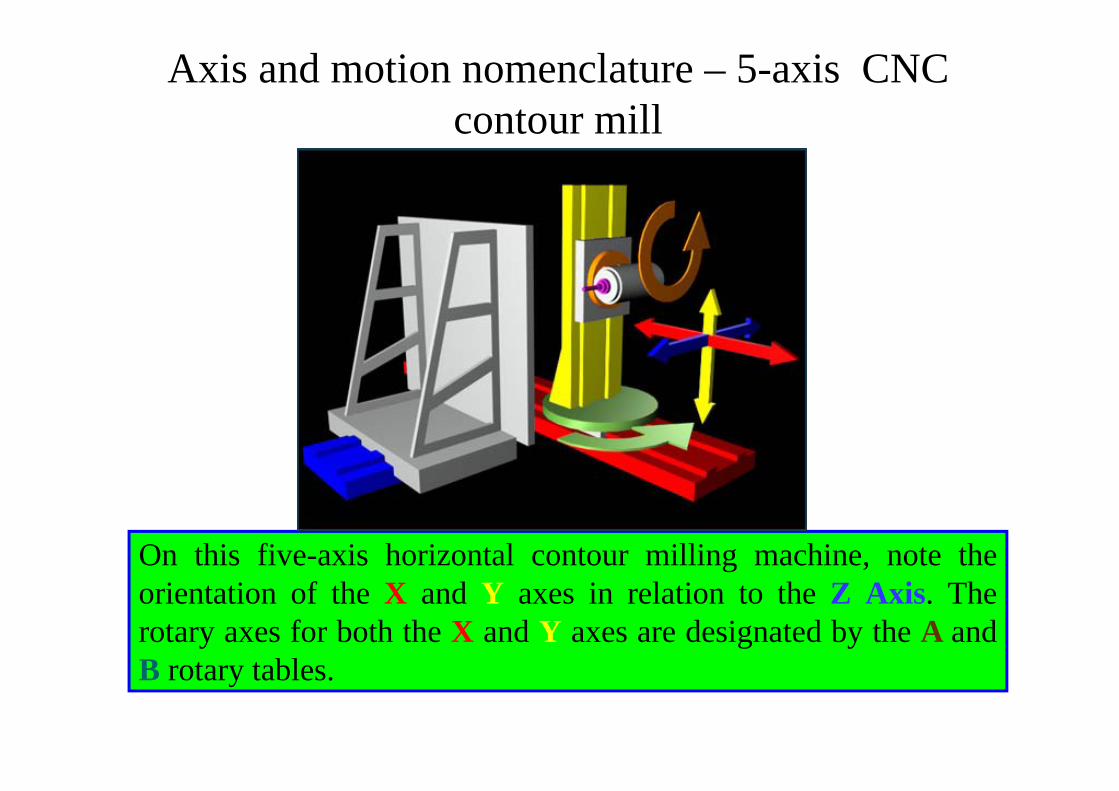
Axis and motion nomenclature – 5-axis CNC contour mill
On this five-axis horizontal contour milling machine, note theorientation of the X and Y axes in relation to the Z Axis. Therotary axes for both the X and Y axes are designated by the A andB rotary tables.

Axis and motion nomenclature – vertical CNC knee mill
On a common vertical knee CNC mill the spindle isstationary while the rest of the components moveaccording to their axis designations (X, Y, and Z).
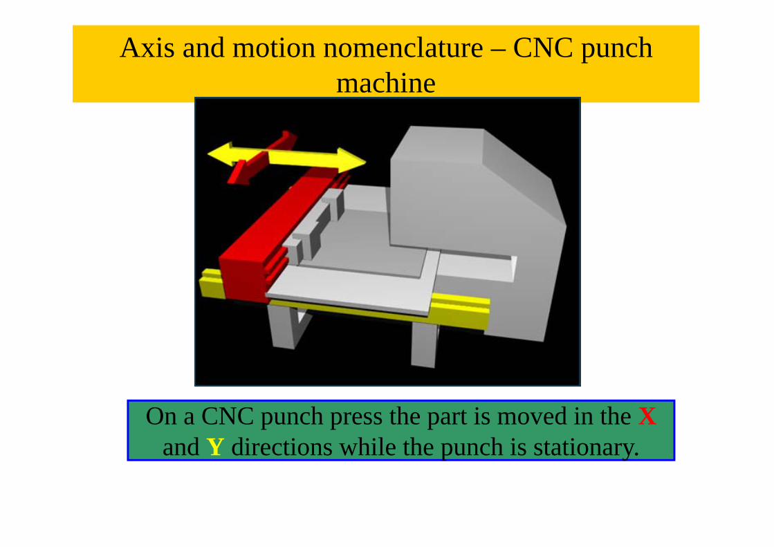
Axis and motion nomenclature – CNC punch machine
On a CNC punch press the part is moved in the X and Y directions while the punch is stationary.

CNC milling fundamentals – The three Cartesian planes
The three planes in the Cartesian coordinate system are XY,XZ, and YZ. These are referred to as G17, G18, and G19,respectively, on the mill.
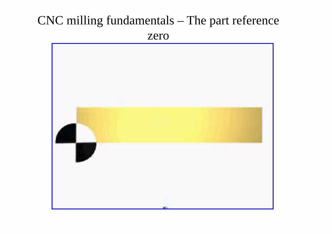
CNC milling fundamentals – The part reference zero
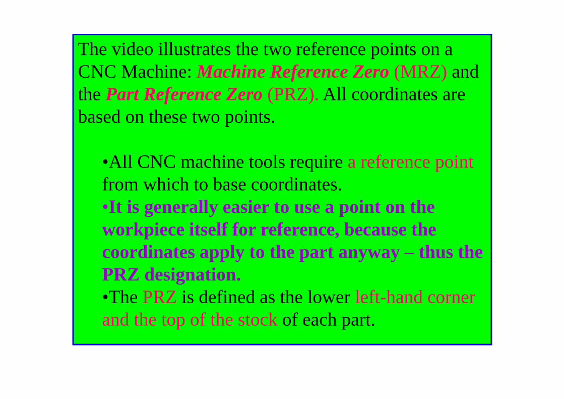
The video illustrates the two reference points on a CNC Machine: Machine Reference Zero (MRZ) and the Part Reference Zero (PRZ). All coordinates are based on these two points.
•All CNC machine tools require a reference pointfrom which to base coordinates. •It is generally easier to use a point on the workpiece itself for reference, because the coordinates apply to the part anyway – thus the PRZ designation.•The PRZ is defined as the lower left-hand corner and the top of the stock of each part.
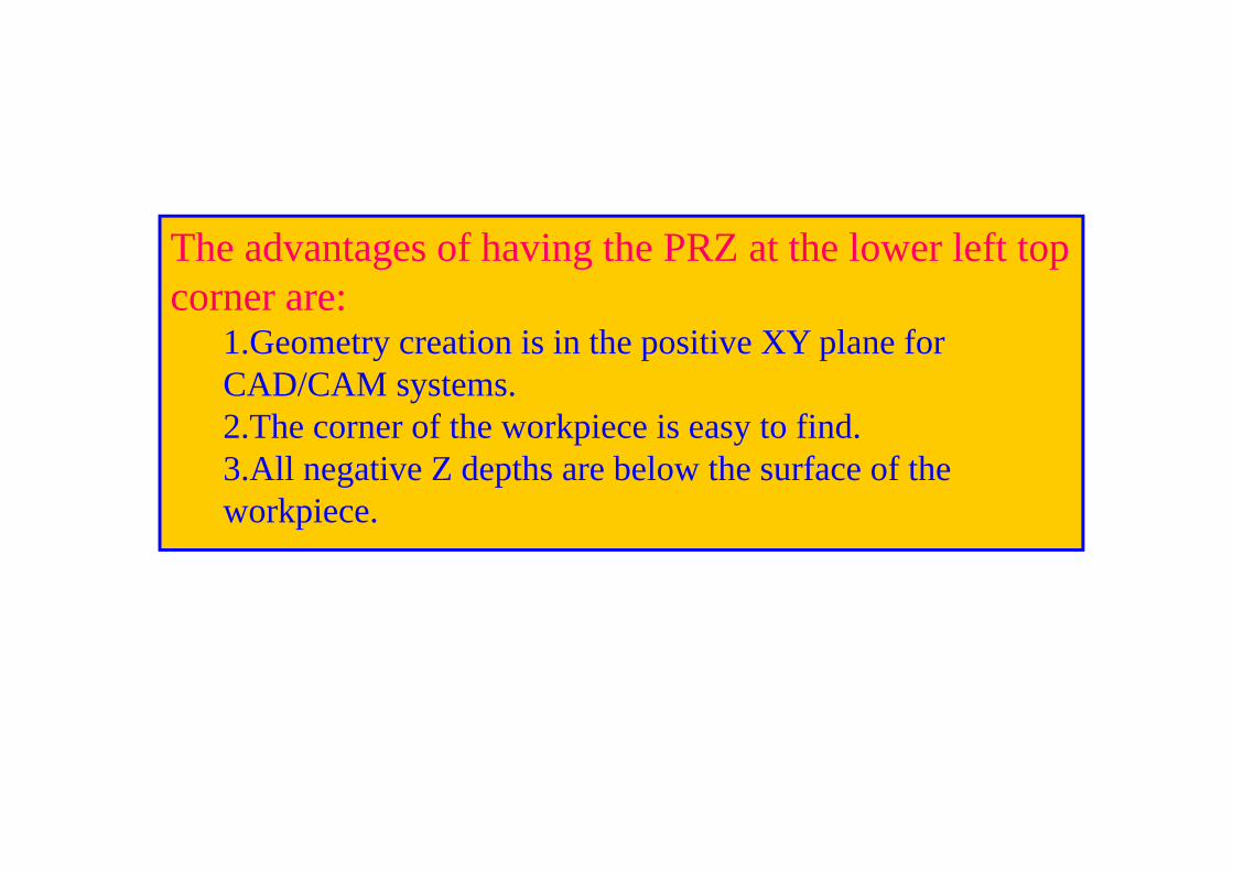
The advantages of having the PRZ at the lower left top corner are:
1.Geometry creation is in the positive XY plane for CAD/CAM systems. 2.The corner of the workpiece is easy to find. 3.All negative Z depths are below the surface of the workpiece.

The Cartesian graph
Cartesian coordinates wereinvented by René Descartes,who is famous for the phrase"I think, therefore I am."Most Cartesian graphs formilling and turning use athree-axis coordinate system,denoted by the X, Y, and Zaxes. These coordinates areused to instruct the machinetool where to move on theworkpiece.
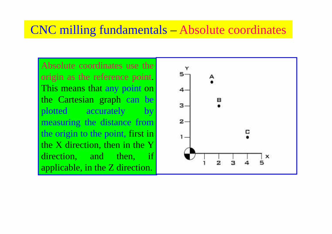
CNC milling fundamentals – Absolute coordinates
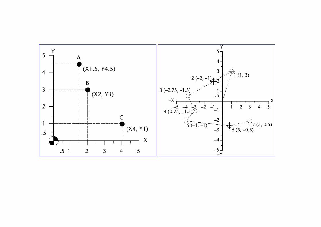
Absolute coordinates use theorigin as the reference point.This means that any point onthe Cartesian graph can beplotted accurately bymeasuring the distance fromthe origin to the point, first inthe X direction, then in the Ydirection, and then, ifapplicable, in the Z direction.
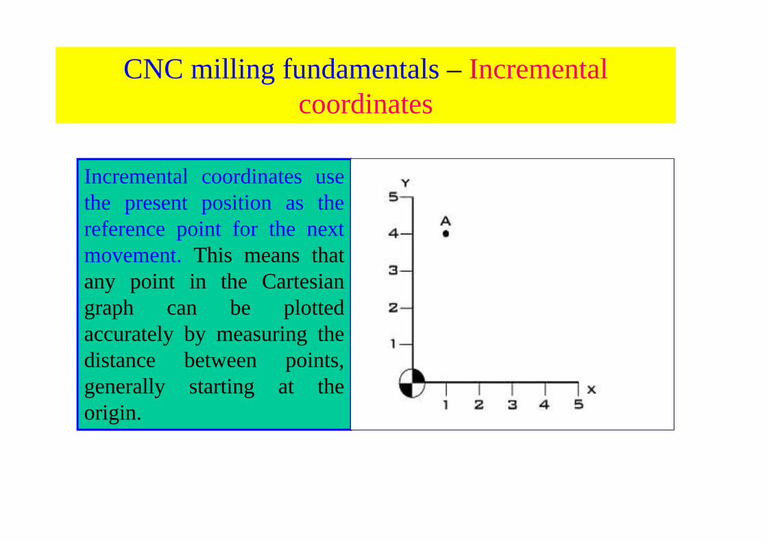
Incremental coordinates usethe present position as thereference point for the nextmovement. This means thatany point in the Cartesiangraph can be plottedaccurately by measuring thedistance between points,generally starting at theorigin.
CNC milling fundamentals – Incremental coordinates
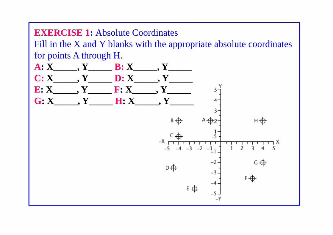
EXERCISE 1: Absolute CoordinatesFill in the X and Y blanks with the appropriate absolute coordinatesfor points A through H.A: X_____, Y_____ B: X_____, Y_____C: X_____, Y_____ D: X_____, Y_____E: X_____, Y_____ F: X_____, Y_____G: X_____, Y_____ H: X_____, Y_____

EXERCISE 2: Incremental CoordinatesFill in the X and Y blanks with the appropriate incrementalcoordinates for points A through H.A: X_____, Y_____ B: X_____, Y_____C: X_____, Y_____ D: X_____, Y_____E: X_____, Y_____ F: X_____, Y_____G: X_____, Y_____ H: X_____, Y_____
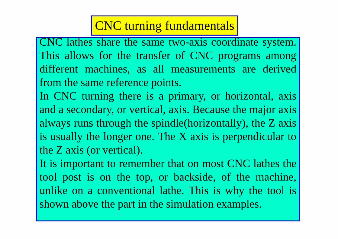
CNC lathes share the same two-axis coordinate system.This allows for the transfer of CNC programs amongdifferent machines, as all measurements are derivedfrom the same reference points.In CNC turning there is a primary, or horizontal, axisand a secondary, or vertical, axis. Because the major axisalways runs through the spindle(horizontally), the Z axisis usually the longer one. The X axis is perpendicular tothe Z axis (or vertical).It is important to remember that on most CNC lathes thetool post is on the top, or backside, of the machine,unlike on a conventional lathe. This is why the tool isshown above the part in the simulation examples.
CNC turning fundamentals
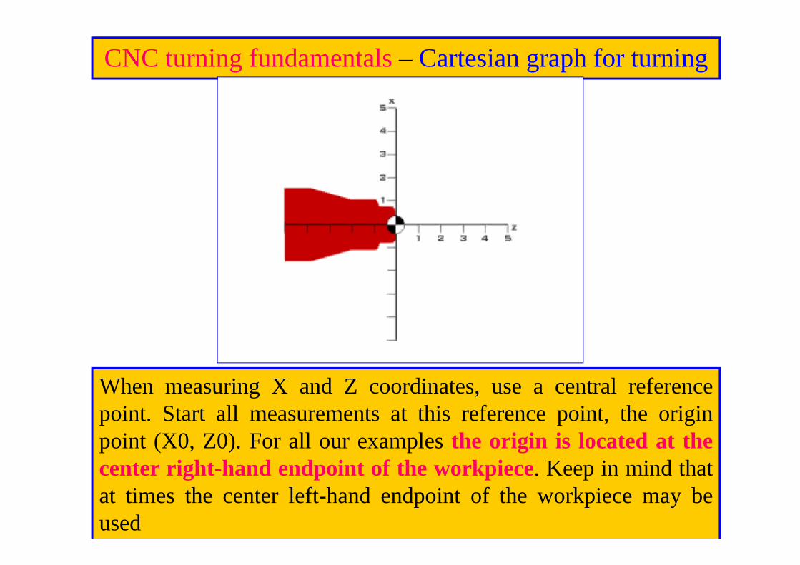
CNC turning fundamentals – Cartesian graph for turning
When measuring X and Z coordinates, use a central referencepoint. Start all measurements at this reference point, the originpoint (X0, Z0). For all our examples the origin is located at thecenter right-hand endpoint of the workpiece. Keep in mind thatat times the center left-hand endpoint of the workpiece may beused
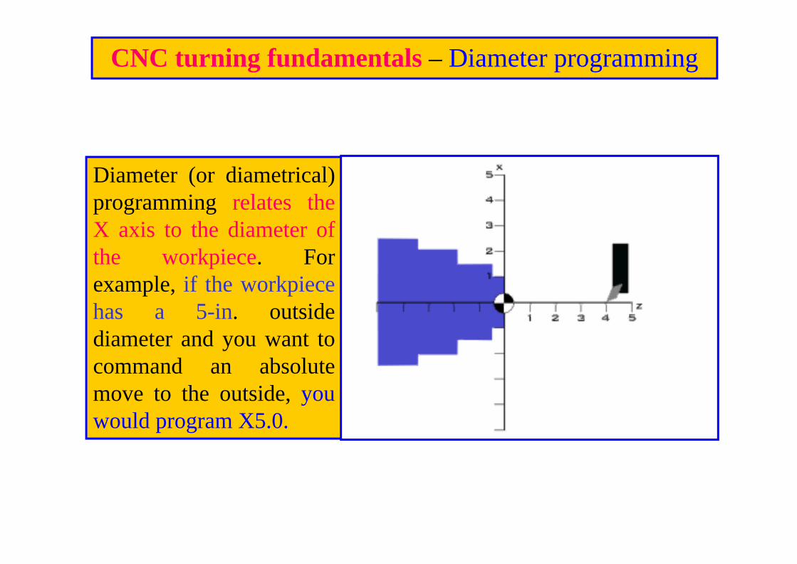
Diameter (or diametrical)programming relates theX axis to the diameter ofthe workpiece. Forexample, if the workpiecehas a 5-in. outsidediameter and you want tocommand an absolutemove to the outside, youwould program X5.0.
CNC turning fundamentals – Diameter programming
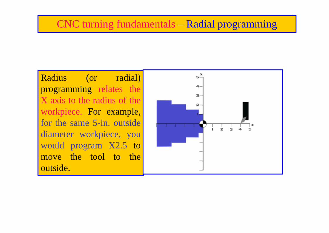
CNC turning fundamentals – Radial programming
Radius (or radial)programming relates theX axis to the radius of theworkpiece. For example,for the same 5-in. outsidediameter workpiece, youwould program X2.5 tomove the tool to theoutside.
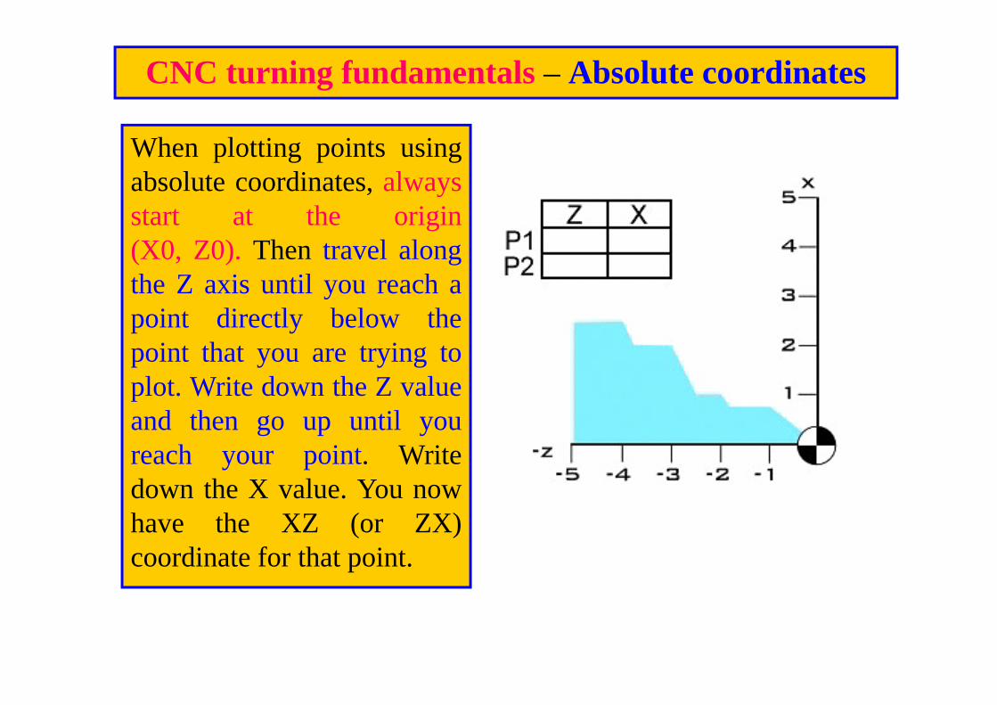
CNC turning fundamentals – Absolute coordinates
When plotting points usingabsolute coordinates, alwaysstart at the origin(X0, Z0). Then travel alongthe Z axis until you reach apoint directly below thepoint that you are trying toplot. Write down the Z valueand then go up until youreach your point. Writedown the X value. You nowhave the XZ (or ZX)coordinate for that point.

CNC turning fundamentals – Incremental coordinates
The second method forfinding points in aCartesian coordinatesystem is by usingincremental coordinates.Incremental, or relative,coordinates use eachsuccessive point tomeasure the nextcoordinate. Instead ofconstantly referring backto the origin, theincremental methodrefers to the previouspoint

EXERCISE 1: Using Incremental Coordinates.Find the diametrical X and Z coordinates for pointsA through E.A: X_____, Z_____ B: X_____, Z_____C: X_____, Z_____ D: X_____, Z_____E: X_____, Z_____

EXERCISE 2: Using Absolute CoordinatesFind the X and Z coordinates for points A through E.A: X_____, Z_____ B: X_____, Z_____C: X_____, Z_____ D: X_____, Z_____E: X_____, Z_____
End of part - 9