CAD Modelling Homework - Design & Technology...
28
CAD Modelling Homework
Transcript of CAD Modelling Homework - Design & Technology...

CAD Modelling
Homework

1 2 3
4 5 6
Below is an engineering component designed using Autodesk Inventor.
Look at the screenshots & identify the tool used to achieve
the result at each stage
1)
2)
3)
4)
5)
6)
1

Below is an engineering component designed using Autodesk Inventor.
Look at the screenshots & identify the tool used to achieve
the result at each stage.
1)
2)
3)
4)
5)
6)
7)
8)
9)
1 2 3
4 5 6
7 8 9
2

Below is an engineering component designed using Autodesk Inventor.
Look at the screenshots & identify the tool used to achieve
the result at each stage.
1)
2)
3)
4)
5)
6)
7)
8)
9)
1 2 3
4 5 6
7 8 9
3

Below is an engineering component designed using Autodesk Inventor.
Look at the screenshots & identify the tool used to achieve
the result at each stage.
1)
2)
3)
4)
5) What is the purpose of the vertical line in slide 1
1 2 3
4
4

Modelling stages using Autodesk Inventor
Engineering Drawing of Pulley Bracket
Stage 1 Stage 2 Stage 3 Stage 4
Stage 5
Stage 6
A bracket is shown in the
Engineering Drawing above.
The stages required to model
the bracket are shown in the
table.
Stage I was drawn using the
3D modelling software and
using the sizes shown in the
Engineering drawing.
A) Describe with reference to
the correct dimensions , how
you would complete the model
from step 2 to
step 6 you should use
sketches to support your
5

Modelling stages using Autodesk Inventor
Engineering Drawing of a Cast Bracket
Stage 1 Stage 2 Stage 3 Stage 4
Stage 5
Stage 6
A bracket is shown in the
Engineering Drawing above.
The stages required to model
the bracket are shown in the
table.
Stage I was drawn using the
3D modelling software and
using the sizes shown in the
Engineering drawing.
A) Describe with reference to
the correct dimensions , how
you would complete the model
from step 2 to step 6 you
should use sketches to
support your answer.
6

Desktop Publishing
Homework

7
..
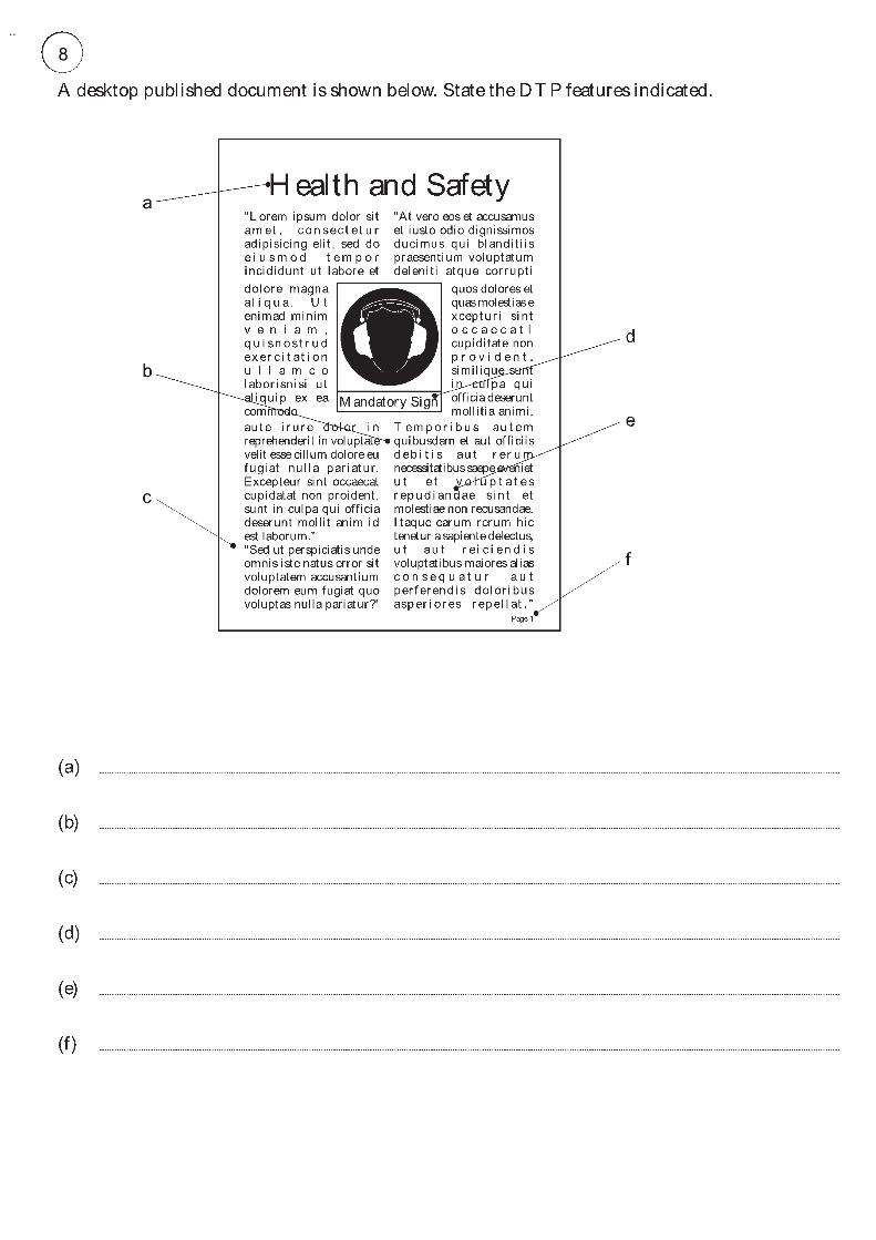
8

9
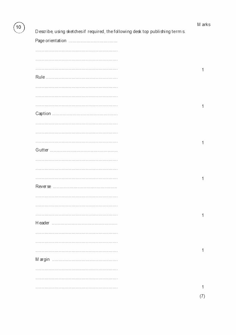
10

Symbol Recognition
Homework

1 2 3 4
5 6 7 8
9 10 11 12
13 14 15 16
17 18 19 20
Write down what the symbols shown below represent : 11
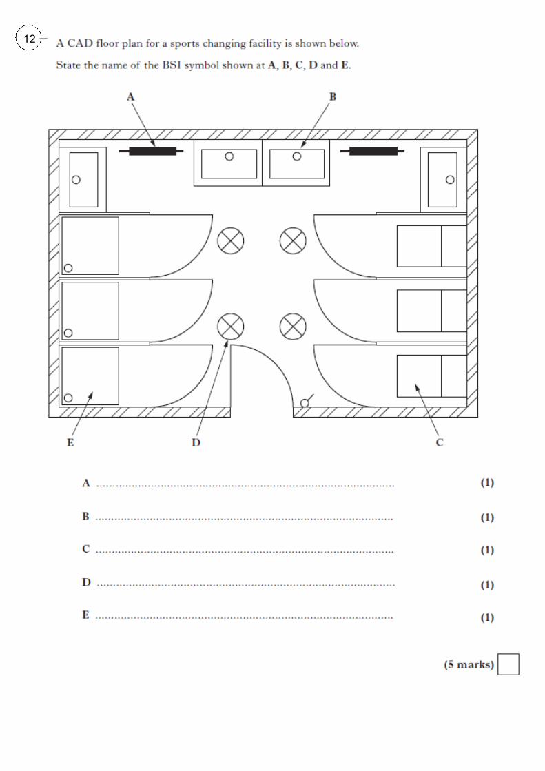
12
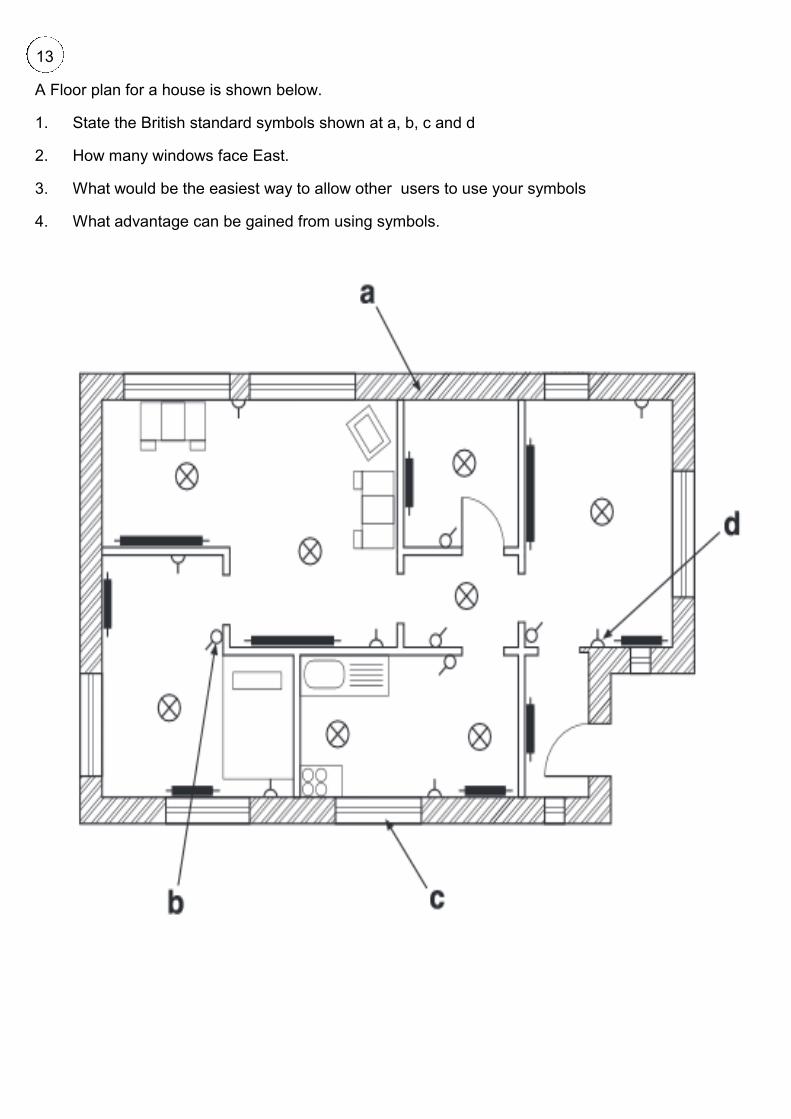
A Floor plan for a house is shown below.
1. State the British standard symbols shown at a, b, c and d
2. How many windows face East.
3. What would be the easiest way to allow other users to use your symbols
4. What advantage can be gained from using symbols.
13

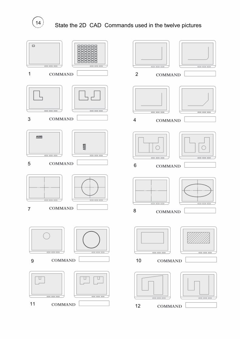
CAD Commands
Homework
1 2
3 4
5 6
7 8
9 10
11 12
State the 2D CAD Commands used in the twelve pictures 14

15

16

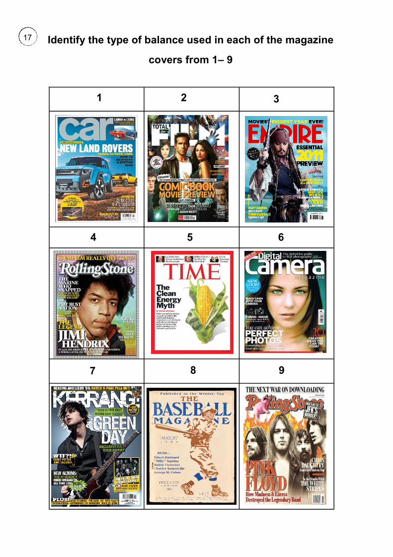
Design Principles and
Elements Homework
1 2 3
4 5 6
7 9 8
Identify the type of balance used in each of the magazine
covers from 1– 9
17

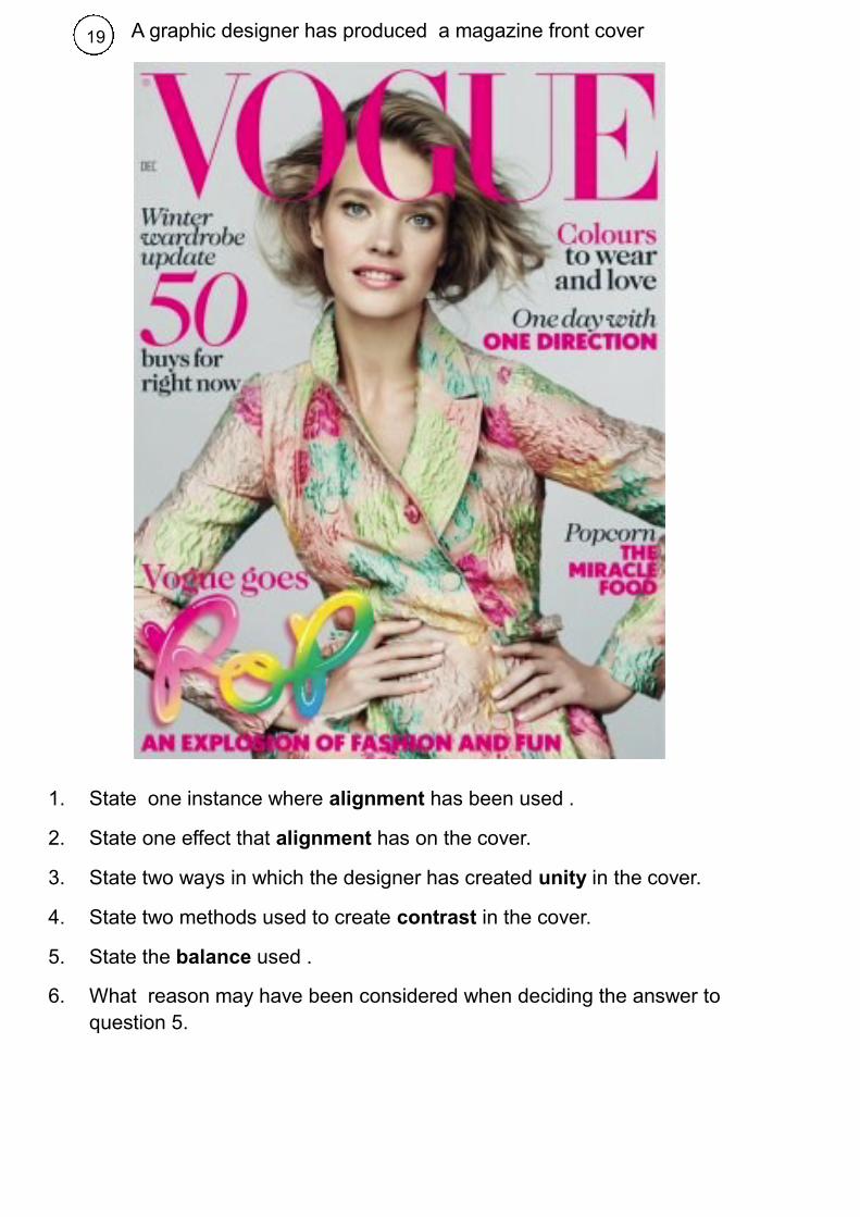
A graphic designer has produced a magazine front cover
1. State one instance where alignment has been used .
2. State one effect that alignment has on the cover.
3. State two ways in which the designer has created unity in the cover.
4. State two methods used to create contrast in the cover.
5. State the balance used .
6. What reason may have been considered when deciding the answer to
question 5.
18
A graphic designer has produced a magazine front cover
1. State one instance where alignment has been used .
2. State one effect that alignment has on the cover.
3. State two ways in which the designer has created unity in the cover.
4. State two methods used to create contrast in the cover.
5. State the balance used .
6. What reason may have been considered when deciding the answer to
question 5.
19

The following names below are associated with Design Principles and Ele-
ments:
1) Line
2) White space
3) Colour
4) Balance
5) Unity
6) Shape
Identify the what is an element and what is a principle.
Chose one Element and one principle and describe them you can use a
sketch.
Thumbnails and visuals are necessary when designing DTP
documents.
What stage are they used?
What is the differences between them? you can use a sketch to help
explain the difference.
20

Interpretation of Views
Homework
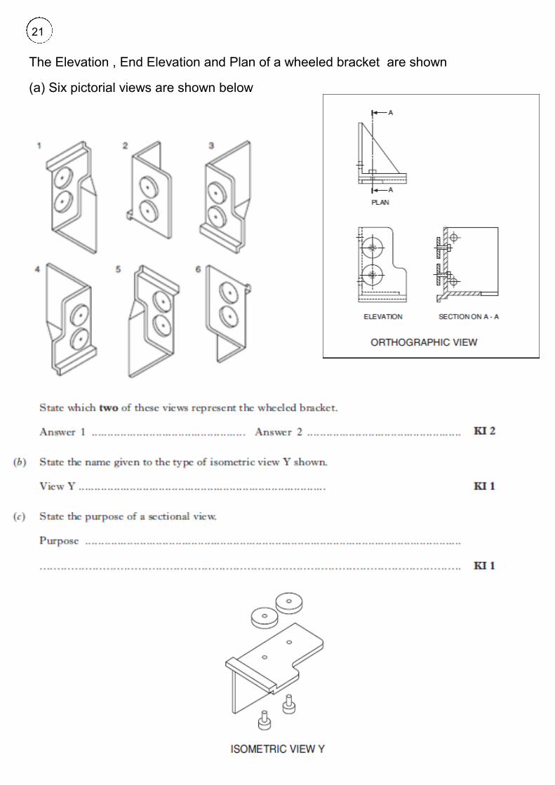
The Elevation , End Elevation and Plan of a wheeled bracket are shown
(a) Six pictorial views are shown below
21

22


![S4Net: Single stage salient-instance segmentation · rather than instance segments. 2.3 Semantic instance segmentation Earlier semantic instance segmentation methods [22–24, 54]](https://static.fdocuments.net/doc/165x107/5fa63c2f83ae5a0cdb44c66e/s4net-single-stage-salient-instance-segmentation-rather-than-instance-segments.jpg)