CAD Mechanical – Part 1jhstechnology.weebly.com/uploads/5/7/6/5/57654325/m… · ·...
15
JONESBORO HIGH SCHOOL ENGINEERNG AND TECHNOLOGY CAD Mechanical Part 1 Assignment 1 Page 1 In this assignment you will learn to identify important terminology and functions of AutoCAD, to begin a new drawing and save data in the proper subdirectory, to use pull-down menus and or tool bars, and scale for the drawing assignments, and draw horizontal lines, vertical lines, dimension lines, and change layers. Detailed instructions will be given for the activities in assignment 1. When this assignment is completed, you will complete three more drawings using the same procedures as performed in the first one. Examples of these drawings are printed on goldenrod paper at the end of this assignment and can be identified as: Sheet Metal Pattern C1 Template for Letter T C2 Template for Letter E C3 Anvil Gasket C4 1. Select the Windows icon at the bottom left of the screen: 2. Select “All Programs” 3. Select “Autodesk” 4. Select “AutoCAD 2016 – English” 5. Select “AutoCAD 2016” – English” Note: This is a big program and it takes time to load. Note: If a pop ask for you to make a selection, choose the one that is recommended. CAD Mechanical – Part 1 Lesson 1 Beginning Drawing Objectives Getting Started
Transcript of CAD Mechanical – Part 1jhstechnology.weebly.com/uploads/5/7/6/5/57654325/m… · ·...

JONESBORO HIGH SCHOOL ENGINEERNG AND TECHNOLOGY
CAD Mechanical Part 1 Assignment 1 Page 1
In this assignment you will learn to identify important terminology and functions of AutoCAD,
to begin a new drawing and save data in the proper subdirectory, to use pull-down menus and or
tool bars, and scale for the drawing assignments, and draw horizontal lines, vertical lines,
dimension lines, and change layers.
Detailed instructions will be given for the activities in assignment 1. When this assignment is
completed, you will complete three more drawings using the same procedures as performed in
the first one. Examples of these drawings are printed on goldenrod paper at the end of this
assignment and can be identified as:
Sheet Metal Pattern C1
Template for Letter T C2
Template for Letter E C3
Anvil Gasket C4
1. Select the Windows icon at the bottom left of the screen:
2. Select “All Programs”
3. Select “Autodesk”
4. Select “AutoCAD 2016 – English”
5. Select “AutoCAD 2016” – English” Note: This is a big program and it takes time to load.
Note: If a pop ask for you to make a selection, choose the one that is recommended.
CAD Mechanical – Part 1 Lesson 1
Beginning Drawing
Objectives
Getting Started

JONESBORO HIGH SCHOOL ENGINEERNG AND TECHNOLOGY
CAD Mechanical Part 1 Assignment 1 Page 2
6. Select “Open Files…”.
7. Click on “Drawing (*.dwg)) in Files of type and change to “Drawing Template (*.dwt)”.
8. Navigate by choosing “Look in” to “Distribution” or (002LJTDist (\\svoc01) (Z:) (Note: IF the
Distribution folder is not available, navigate to http://jhstechnology.weebly.com/mechanical-
cad.html and download all files to your U: drive. Then navigate to your U: drive in place of the
Distribution folder.)
JONESBORO HIGH SCHOOL ENGINEERNG AND TECHNOLOGY
CAD Mechanical Part 1 Assignment 1 Page 3
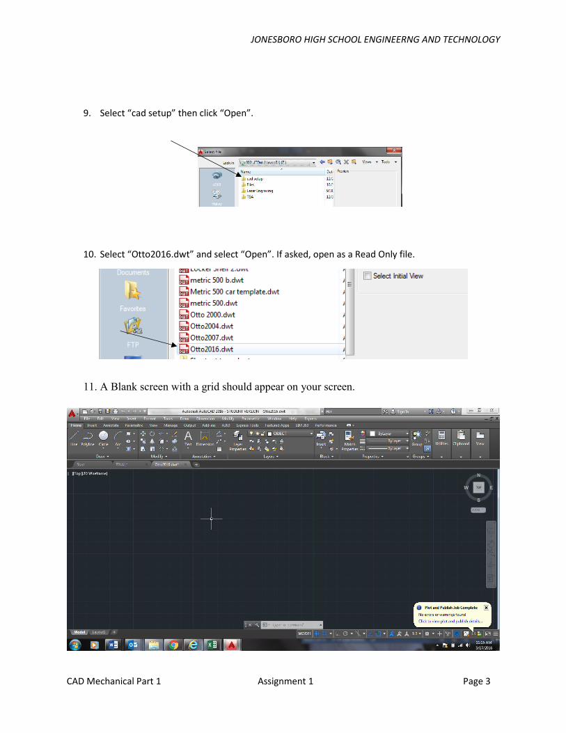
9. Select “cad setup” then click “Open”.
10. Select “Otto2016.dwt” and select “Open”. If asked, open as a Read Only file.
11. A Blank screen with a grid should appear on your screen.
JONESBORO HIGH SCHOOL ENGINEERNG AND TECHNOLOGY
CAD Mechanical Part 1 Assignment 1 Page 4
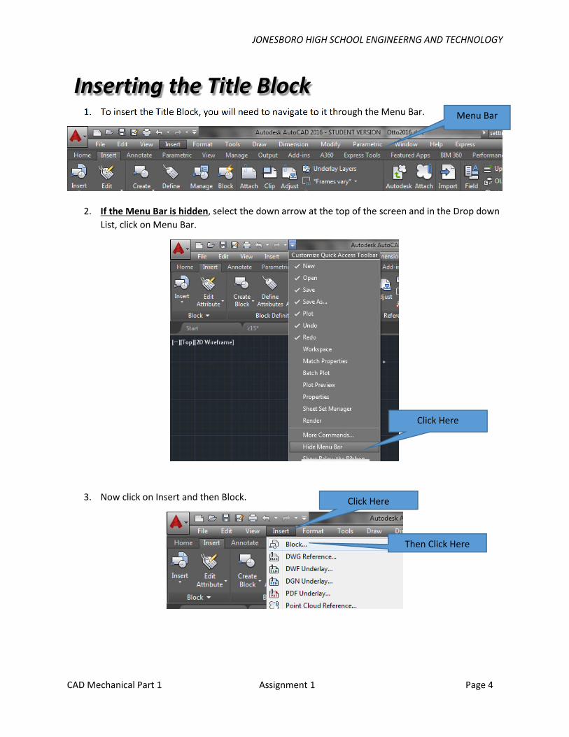
1. To insert the Title Block, you will need to navigate to it through the Menu Bar.
2. If the Menu Bar is hidden, select the down arrow at the top of the screen and in the Drop down
List, click on Menu Bar.
3. Now click on Insert and then Block.
Inserting the Title Block Menu Bar
Click Here
Click Here
Then Click Here

JONESBORO HIGH SCHOOL ENGINEERNG AND TECHNOLOGY
CAD Mechanical Part 1 Assignment 1 Page 5
4. A Pop Up window will appear.
5. Make sure your Pop up window is set up exactly the same and press OK.
12.
13.
1. When you click the OK button, type the information into the title block dialog box as
illustrated and then click OK:
Setting Up the Title Block

JONESBORO HIGH SCHOOL ENGINEERNG AND TECHNOLOGY
CAD Mechanical Part 1 Assignment 1 Page 6
2. You will notice that a title block (including borderlines) with the drawing information
appears on the computer screen. You will draw the assignment inside the borderlines.
5. If it is easier for you, refer to the drawing entitled “Sheet Metal Pattern,” from the
drawing folder in the distribution folder at this time .Use it for interpreting the
required dimensions for the assignment. Keep the drawing available as you read
instructions from this manual.
6. You will need to become familiar with the AutoCAD ribbon menus and the tabs. It is
also imperative that you to become familiar with the command prompt at the bottom of
the screen. If you know the name of a command you are using, it is often quicker to type
the command at the command prompt rather than waste time searching menus.

JONESBORO HIGH SCHOOL ENGINEERNG AND TECHNOLOGY
CAD Mechanical Part 1 Assignment 1 Page 7
7. In the command prompt window type snap and press the Enter key. Change the snap
from 1/8th to 1/2 inch. By changing the snap, it simply means that each time you move
the mouse, the cross hair on the screen will move 1/2 inch instead of 1/8 inch. The snap
will remain the same until changed again by the user.
8. In the command line, type “Grid”. Select “On”.
9. From the Home tab on the left side, you are now going to select the line tool icon.
10. This icon enables you to draw lines. You will begin the sheet metal pattern drawing by
selecting the first point in the lower left corner above the title block area. Draw the
first line up 5” as noted on the Drawing C1. Select the first point of the line by
Information Time-Out There are three ways to view your coordinates.
Relative, based on the last point clicked. Example: 2 1/64<, 5, 0
Absolute, based on an origin of 0, 0. Example: 3, 2 7/8, 0
Direct Distance Entry, based on the last point clicked plus the user moving in the
correct direction and keying in the distance.
It is best to work in the Relative mode. The coordinate’s mode can be changed by pressing
the F6 key and observing the coordinates display in the lower left corner of the screen.

JONESBORO HIGH SCHOOL ENGINEERNG AND TECHNOLOGY
CAD Mechanical Part 1 Assignment 1 Page 8
pressing the left mouse button. When the line reaches 5”, press the left mouse button
again to complete the line. Move the mouse to the right 2” for the next point as
illustrated below:
Observe the relative coordinate display on the screen as you draw: 1 ½ means 1 ½
inches.

JONESBORO HIGH SCHOOL ENGINEERNG AND TECHNOLOGY
CAD Mechanical Part 1 Assignment 1 Page 9
11. Using the measurements from the drawing, continue the drawing
12. Connect the lines for each segment by pressing the left mouse button. When you close
the drawing after the last line segment, press either the Enter or ESC keys. When
completed, the drawing should appear as illustrated below:

JONESBORO HIGH SCHOOL ENGINEERNG AND TECHNOLOGY
CAD Mechanical Part 1 Assignment 1 Page 10
13. In the next part of the assignment, you will learn to change layers and place dimensions
onto the drawing as illustrated on the sample drawing C1.
14. You will need to change to the dimension layer by selecting this layer from the object
properties menu bar. You will change from the object layer to the dimension layer by
clicking the scroll-down arrow or triangle and selecting the dimension layer. The
dimension layer will now be the current layer.
15. Click on “Object” on the Ribbon bar.
16. Select “DIMENSION”.
17. You will need to change the snap back to 1/8th from 1/2 inch. Do this at the command
prompt by typing snap and pressing the enter key. Then make the change.
18. You are going to make linear dimensions for both horizontal and vertical dimensions.
You will first do the horizontal dimensions across the top of the drawing.

JONESBORO HIGH SCHOOL ENGINEERNG AND TECHNOLOGY
CAD Mechanical Part 1 Assignment 1 Page 11
19. Dimensions should be drawn 3/8’s from the object and 3/8’s apart from one another.
20. Select the linear dimension icon from the dimension toolbar. Move the mouse to the
upper left corner of the drawing. A small purple square will snap onto the endpoint of
the drawing. This is the osnap feature. Osnap means object snap. The snap will jump
to any intersection on the object where you move the mouse near as illustrated below:
21. Select the first extension line end point as indicated above and then select the second
point for the extension lines. These points are selected by clicking the left mouse
button. When the second point is confirmed, move the cursor with the mouse above the
drawing to a location of 3/8” to locate the dimension line as illustrated below:
3/8
3/8

JONESBORO HIGH SCHOOL ENGINEERNG AND TECHNOLOGY
CAD Mechanical Part 1 Assignment 1 Page 12
22. Repeat the command by pressing either the space bar or the enter key and locating the
points until all of the horizontal dimensions are completed.
23. Repeat these steps for the vertical dimensions. The second end point for the second
extension line should be selected at the point indicated below:
24. The extension lines for the vertical dimensions need to be selected from the inside
points of the drawing when applicable in order to draw the extension line long enough.
Continue all points until all vertical lines are drawn. Remember that all points are
selected with the left mouse button. To repeat the command for another dimension,
remember to press either the space bar or the enter key. This saves keystrokes and
allows you the opportunity to repeat the dimension command.

JONESBORO HIGH SCHOOL ENGINEERNG AND TECHNOLOGY
CAD Mechanical Part 1 Assignment 1 Page 13
25. The completed drawing should appear as illustrated below:
26. Select save from the pull down menu or the save icon.
27. When the save options appear, you must navigate to your assigned class folder on the
lab’s network server. If you do not place the file in the correct location, you will receive
read only messages and the file will not be saved. Click the drop down arrow to the right
of the Save In Window. A menu tree will appear. Select Computer. Locate the 002LJT
U: Drive Folder assigned to you and click it.

JONESBORO HIGH SCHOOL ENGINEERNG AND TECHNOLOGY
CAD Mechanical Part 1 Assignment 1 Page 14
28. Create a New Folder and name it Mechanical CAD.
29. Click the File name window and name the file C1 (LAST NAME FIRST
INITIAL)(PERIOD). Click the save button and the file should be saved.
30. Make sure that Files of type has AutoCAD 2013 (*.dwg) is selected.
31. If you need to change Files of type: click on the bar next to it and a menu list of file types
will appear. Click on AutoCAD 2013 Drawing (*.dwg)
32. Complete drawings C2, C3 and C4 before answering the questions or proceeding to
Activity 2.
Instructions: Copy the following terms into your notebook and define them.
Ribbon
Line
Vertical
Object Layer
Crosshair
Save
Save As
Border
Snap
Osnap
Terms to Know

JONESBORO HIGH SCHOOL ENGINEERNG AND TECHNOLOGY
CAD Mechanical Part 1 Assignment 1 Page 15
Border Layer
Ortho
Coordinate Display
Home
Horizontal
Layer Control
Template .dwt
Drawing .dwg
Dimension Layer