Cabling Color
61
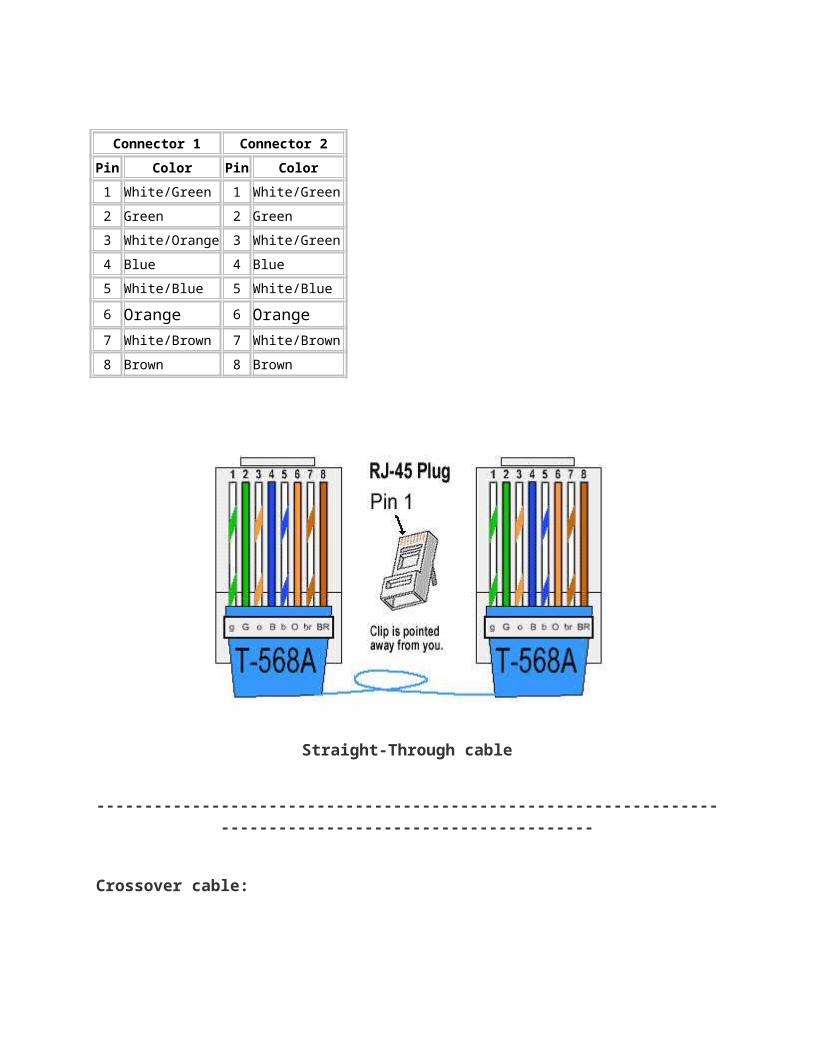
Connector 1 Connector 2 Pin Color Pin Color 1 White/Green 1 White/Green 2 Green 2 Green 3 White/Orange 3 White/Green 4 Blue 4 Blue 5 White/Blue 5 White/Blue 6 Orange 6 Orange 7 White/Brown 7 White/Brown 8 Brown 8 Brown Straight-Through cable ----------------------------------------------------------------- --------------------------------------- Crossover cable:
-
Upload
connie-marie-samiano-magno -
Category
Documents
-
view
112 -
download
1
Transcript of Cabling Color
Connector 1 Connector 2
Pin Color Pin Color
1 White/Green 1 White/Green
2 Green 2 Green
3 White/Orange 3 White/Green
4 Blue 4 Blue
5 White/Blue 5 White/Blue
6 Orange 6 Orange7 White/Brown 7 White/Brown
8 Brown 8 Brown
Straight-Through cable
--------------------------------------------------------------------------------------------------------
Crossover cable:

Connector 1 Connector 2
Pin Color Pin Color
1 White/Green 1 White/ Orange
2 Green 2 Orange
3 White/Orange 3 White/Green
4 Blue 4 Blue
5 White/Blue 5 White/Blue
6 Orange 6 Green
7 White/Brown 7 White/Brown
8 Brown 8 Brown
Crossover cable
------------------------------------------------
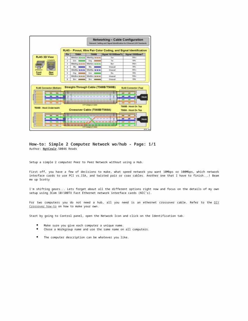
How-to: Simple 2 Computer Network wo/hub - Page: 1/1Author: NgtCrwlr.50046 Reads
Setup a simple 2 computer Peer to Peer Network without using a Hub.
First off, you have a few of decisions to make, what speed network you want 10Mbps or 100Mbps, which network interface cards to use PCI vs.ISA, and twisted pair or coax cables. Another one that I have to finish...! Beam me up Scotty
I'm shifting gears... Lets forget about all the different options right now and focus on the details of my own setup using 3Com 10/100TX Fast Ethernet network interface cards (NIC's).
For two computers you do not need a hub, all you need is an ethernet crossover cable. Refer to the DIY Crossover how-to on how to make your own.
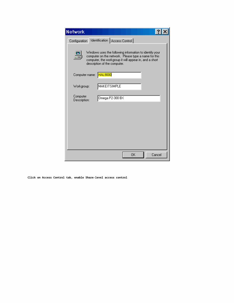
Start by going to Control panel, open the Network Icon and click on the Identification tab.
Make sure you give each computer a unique name.
Chose a Workgroup name and use the same name on all computers.
The computer description can be whatever you like.
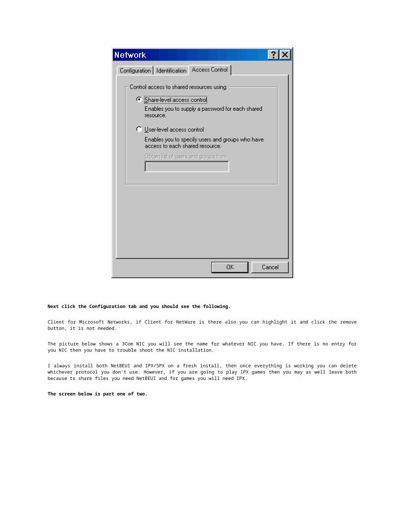
Click on Access Control tab, enable Share-level access control
Next click the Configuration tab and you should see the following.
Client for Microsoft Networks, if Client for NetWare is there also you can highlight it and click the remove button, it is not needed.
The picture below shows a 3Com NIC you will see the name for whatever NIC you have. If there is no entry for you NIC then you have to trouble shoot the NIC installation.
I always install both NetBEUI and IPX/SPX on a fresh install, then once everything is working you can delete whichever protocol you don't use. However, if you are going to play IPX games then you may as well leave both because to share files you need NetBEUI and for games you will need IPX.
The screen below is part one of two.
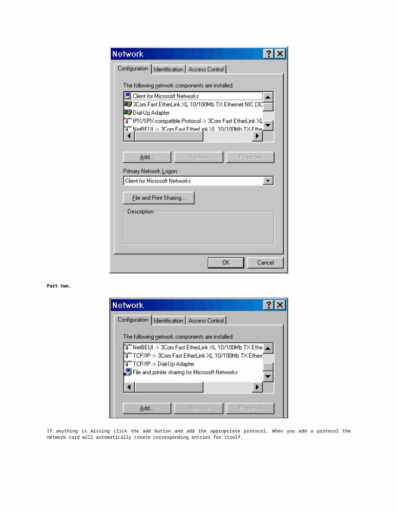
Part two.
If anything is missing click the add button and add the appropriate protocol. When you add a protocol the network card will automatically create corresponding entries for itself.
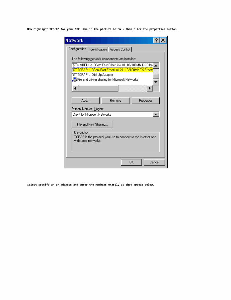
Now highlight TCP/IP for your NIC like in the picture below - then click the properties button.
Select specify an IP address and enter the numbers exactly as they appear below.

On the second and third machines use the same numbers except increment the last digit for each machine. Example the second machine would be 192.168.0.2 and a third machine would be 192.168.0.3
The subnet Mask stays the same for all machines and in this example we are using 255.255.255.0
Next click on DNS Configuration and Enable DNS
For Host enter the name you gave this machine in the first step under the Identification tab. On the other machines use the unique name given to each machine from step one
Enter 192.168.0.1 into the field with the dots and click the add button. Use this same number for all machines in the network.
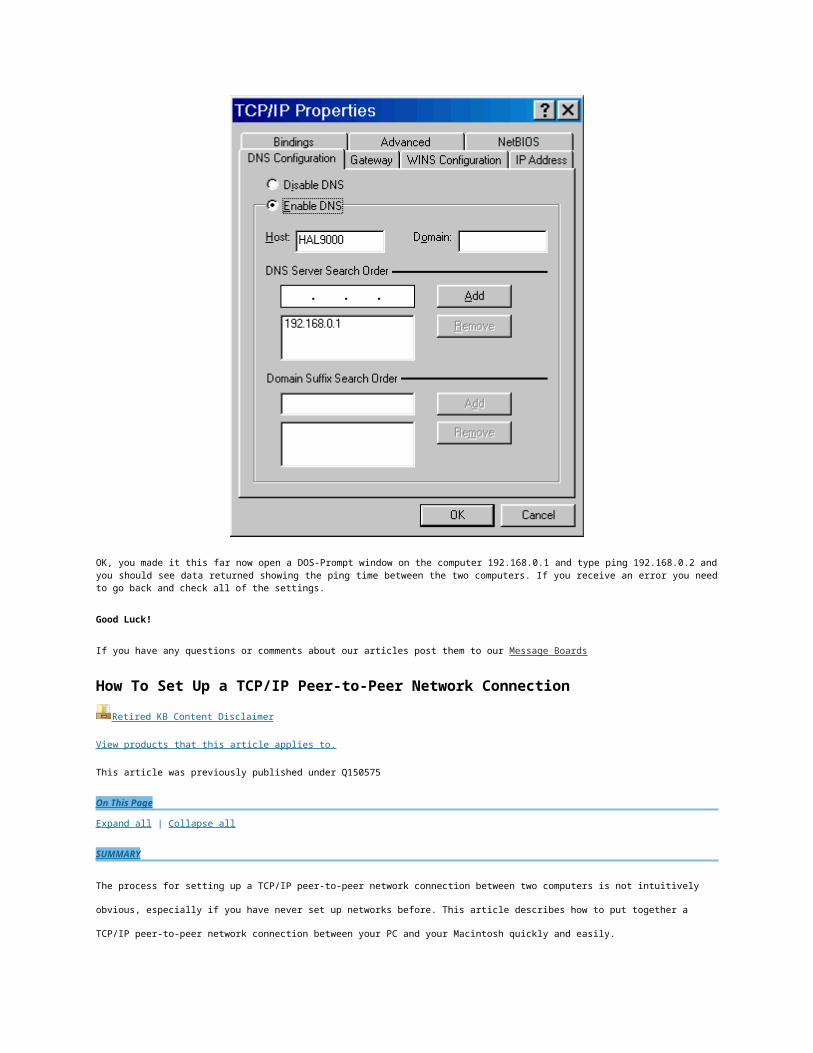
OK, you made it this far now open a DOS-Prompt window on the computer 192.168.0.1 and type ping 192.168.0.2 and you should see data returned showing the ping time between the two computers. If you receive an error you need to go back and check all of the settings.
Good Luck!
If you have any questions or comments about our articles post them to our Message Boards
How To Set Up a TCP/IP Peer-to-Peer Network Connection
Retired KB Content Disclaimer
View products that this article applies to.
This article was previously published under Q150575
On This Page
Expand all | Collapse all
SUMMARY
The process for setting up a TCP/IP peer-to-peer network connection between two computers is not intuitively obvious, especially if
you have never set up networks before. This article describes how to put together a TCP/IP peer-to-peer network connection
between your PC and your Macintosh quickly and easily.
Back to the top
MORE INFORMATION
General Physical Network Connection Issues
There are three common types of network cabling: Twisted Pair, ThinNet, and ThickNet.
If you are using twisted-pair, which is thin wire with wide phone connectors (RJ-45), both your PC and Macintosh need to be plugged
into a network hub so power is flowing through the network cable to carry data. Depending on the manufacturer and model, hubs
usually allow between four and 20 machines to network.
Typically no extra hardware is required if you are using either ThinNet, which looks like Cable TV wiring with a round plug, or
ThickNet, which is heavy, 1/4 inch cable with D-shell 15-pin connectors. The network cards can be connected to each other directly.
Several newer Macintosh models have a built-in network connector called FriendlyNet. You are required to obtain a network
transceiver, such as Asante's 10T Adapter, to use one of the cables mentioned above.
Back to the top
Choosing IP Addresses for Your Machines
For simplicity, use class B IP addresses for your peer-to-peer network. The specifications for class B IP addresses are as follows:
The first digit of the IP address must be between 128 to 191 inclusively.
The subnet mask is: 255.255.0.0
The first two digits of the IP address must match on both machines. For example:
machine1: 150.100.100.10
machine2: 150.100.250.20
NOTE: When creating an IP address, avoid using 0 or 255 for any of the digits because these numbers are reserved for special use.
Here's a good example of a set of IP address to use:
Macintosh: 150.100.100.10
PC Running Windows NT or Windows 95: 150.100.100.20
Back to the top
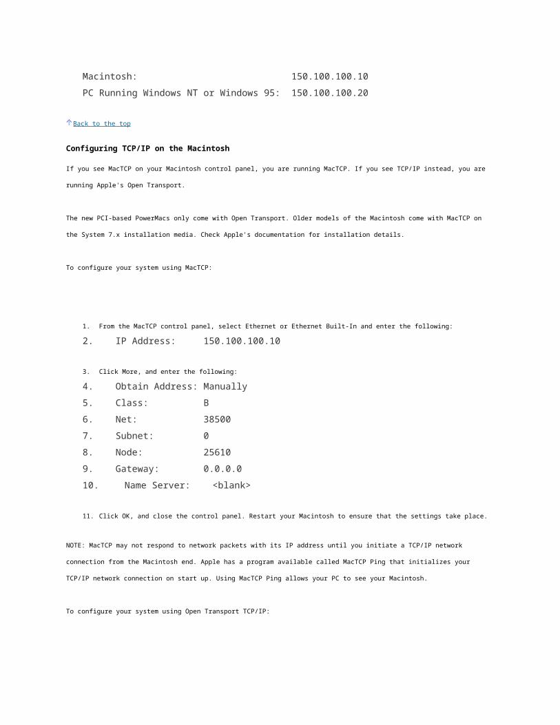
Configuring TCP/IP on the Macintosh
If you see MacTCP on your Macintosh control panel, you are running MacTCP. If you see TCP/IP instead, you are running Apple's
Open Transport.
The new PCI-based PowerMacs only come with Open Transport. Older models of the Macintosh come with MacTCP on the System 7.x
installation media. Check Apple's documentation for installation details.
To configure your system using MacTCP:
1. From the MacTCP control panel, select Ethernet or Ethernet Built-In and enter the following:
2. IP Address: 150.100.100.10
3. Click More, and enter the following:
4. Obtain Address: Manually
5. Class: B
6. Net: 38500
7. Subnet: 0
8. Node: 25610
9. Gateway: 0.0.0.0
10. Name Server: <blank>
11. Click OK, and close the control panel. Restart your Macintosh to ensure that the settings take place.
NOTE: MacTCP may not respond to network packets with its IP address until you initiate a TCP/IP network connection from the
Macintosh end. Apple has a program available called MacTCP Ping that initializes your TCP/IP network connection on start up. Using
MacTCP Ping allows your PC to see your Macintosh.
To configure your system using Open Transport TCP/IP:
1. Go to the TCP/IP control panel, and enter the following settings:
2. Connect Via: ethernet
3. Configure: manually
4. IP Address: 150.100.100.10
5. Domain Name: <blank>
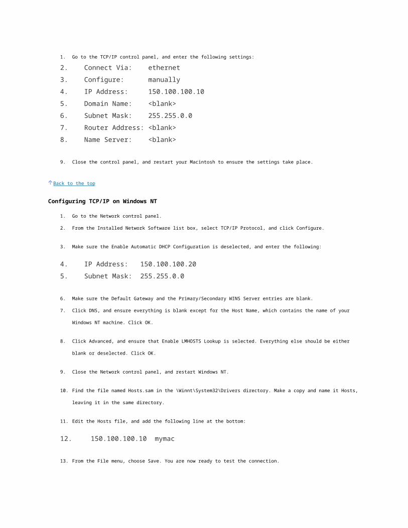
6. Subnet Mask: 255.255.0.0
7. Router Address: <blank>
8. Name Server: <blank>
9. Close the control panel, and restart your Macintosh to ensure the settings take place.
Back to the top
Configuring TCP/IP on Windows NT
1. Go to the Network control panel.
2. From the Installed Network Software list box, select TCP/IP Protocol, and click Configure.
3. Make sure the Enable Automatic DHCP Configuration is deselected, and enter the following:
4. IP Address: 150.100.100.20
5. Subnet Mask: 255.255.0.0
6. Make sure the Default Gateway and the Primary/Secondary WINS Server entries are blank.
7. Click DNS, and ensure everything is blank except for the Host Name, which contains the name of your Windows NT
machine. Click OK.
8. Click Advanced, and ensure that Enable LMHOSTS Lookup is selected. Everything else should be either blank or
deselected. Click OK.
9. Close the Network control panel, and restart Windows NT.
10. Find the file named Hosts.sam in the \Winnt\System32\Drivers directory. Make a copy and name it Hosts, leaving it in the
same directory.
11. Edit the Hosts file, and add the following line at the bottom:
12. 150.100.100.10 mymac
13. From the File menu, choose Save. You are now ready to test the connection.
Back to the top
Configuring TCP/IP on Windows 95
1. From the Network control panel, select TCP/IP, and click Properties.
2. Go to WINS Configuration, and select Disable WINS resolution.
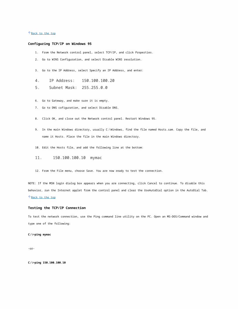
3. Go to the IP Address, select Specify an IP Address, and enter:
4. IP Address: 150.100.100.20
5. Subnet Mask: 255.255.0.0
6. Go to Gateway, and make sure it is empty.
7. Go to DNS cofiguration, and select Disable DNS.
8. Click OK, and close out the Network control panel. Restart Windows 95.
9. In the main Windows directory, usually C:\Windows, find the file named Hosts.sam. Copy the file, and name it Hosts. Place
the file in the main Windows directory.
10. Edit the Hosts file, and add the following line at the bottom:
11. 150.100.100.10 mymac
12. From the File menu, choose Save. You are now ready to test the connection.
NOTE: If the MSN login dialog box appears when you are connecting, click Cancel to continue. To disable this behavior, run the
Internet applet from the control panel and clear the UseAutoDial option in the AutoDial Tab.
Back to the top
Testing the TCP/IP Connection
To test the network connection, use the Ping command line utility on the PC. Open an MS-DOS/Command window and type one of
the following:
C:\>ping mymac
-or-
C:\>ping 150.100.100.10
Replace 150.100.100.10 and mymac with whatever you set in the Hosts file. Using mymac causes the TCP/IP service to look up the
name in the Hosts file to resolve it to an IP address. The expected output from Ping looks like the following:
C:\>ping 150.100.100.10
Pinging 150.100.100.10 with 32 bytes of data:
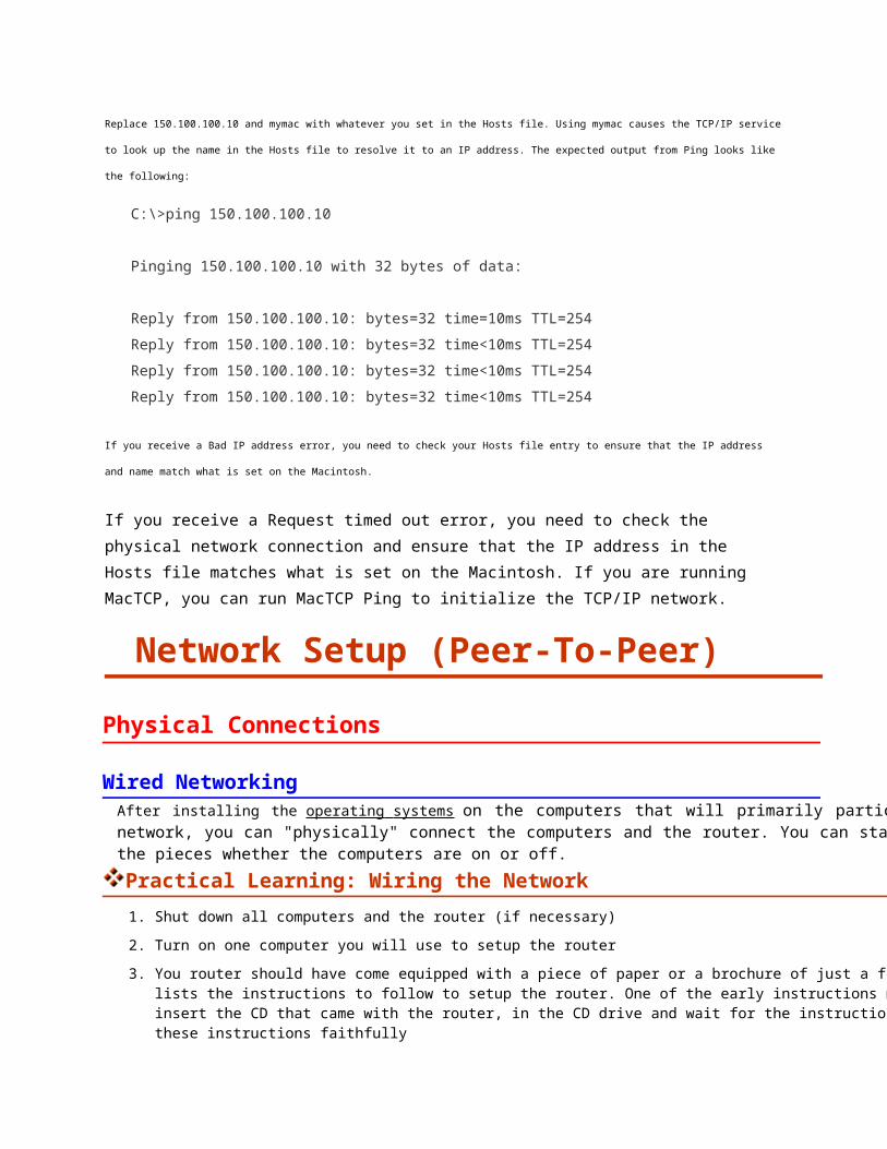
Reply from 150.100.100.10: bytes=32 time=10ms TTL=254
Reply from 150.100.100.10: bytes=32 time<10ms TTL=254
Reply from 150.100.100.10: bytes=32 time<10ms TTL=254
Reply from 150.100.100.10: bytes=32 time<10ms TTL=254
If you receive a Bad IP address error, you need to check your Hosts file entry to ensure that the IP address and name match what is
set on the Macintosh.
If you receive a Request timed out error, you need to check the physical network connection and ensure
that the IP address in the Hosts file matches what is set on the Macintosh. If you are running MacTCP,
you can run MacTCP Ping to initialize the TCP/IP network.
Network Setup (Peer-To-Peer)
Physical Connections
Wired NetworkingAfter installing the operating systems on the computers that will primarily participate in the network, you can "physically" connect the computers and the router. You can start connecting the pieces whether the computers are on or off.
Practical Learning: Wiring the Network
1. Shut down all computers and the router (if necessary)
2. Turn on one computer you will use to setup the router
3. You router should have come equipped with a piece of paper or a brochure of just a few pages that lists the instructions to follow to setup the router. One of the early instructions may ask you to insert the CD that came with the router, in the CD drive and wait for the instructions. Follow these instructions faithfully
4. After setting up and configuring the router, turn it off and turn off the computer you used to set it up (this step is optional)
5. Connect each of the other computers to the router using an RJ-45 cable for each connection:
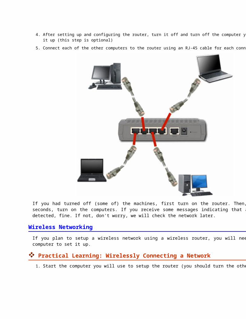
If you had turned off (some of) the machines, first turn on the router. Then, after a few seconds, turn on the computers. If you receive some messages indicating that a network was detected, fine. If not, don't worry, we will check the network later.
Wireless Networking
If you plan to setup a wireless network using a wireless router, you will need to use one computer to set it up.
Practical Learning: Wirelessly Connecting a Network
1. Start the computer you will use to setup the router (you should turn the others off):
2. Most, if not all, wireless routers come with very easy to follow instructions. Most of them usually ask you to first insert the CD that
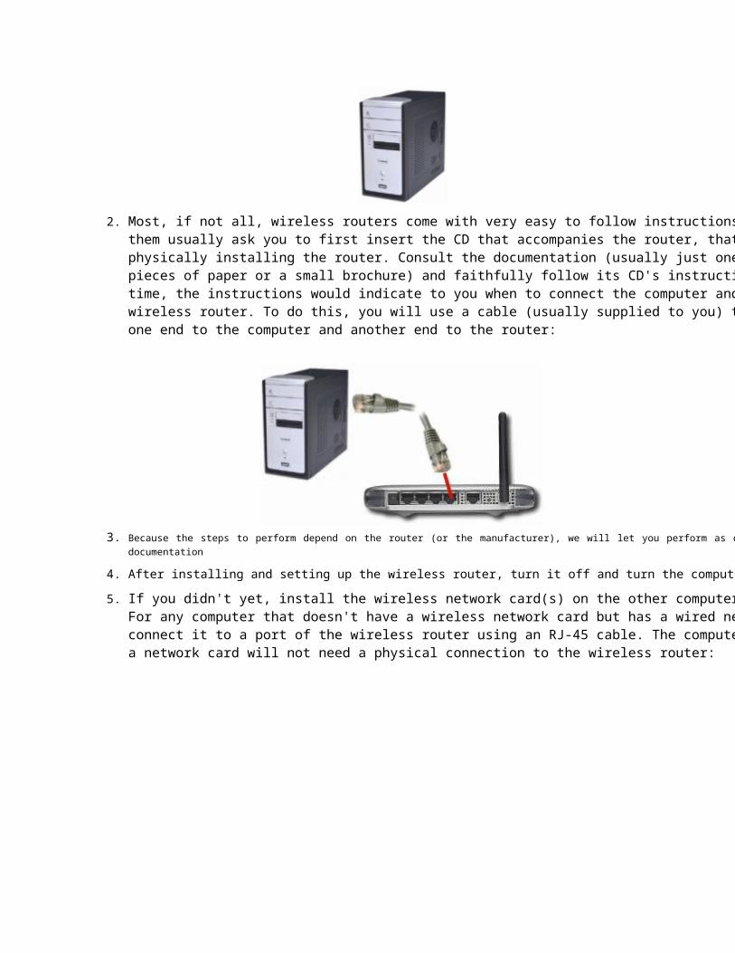
accompanies the router, that is, before physically installing the router. Consult the documentation (usually just one or a few pieces of paper or a small brochure) and faithfully follow its CD's instructions. At one time, the instructions would indicate to you when to connect the computer and the wireless router. To do this, you will use a cable (usually supplied to you) to connect one end to the computer and another end to the router:
3. Because the steps to perform depend on the router (or the manufacturer), we will let you perform as described by their documentation
4. After installing and setting up the wireless router, turn it off and turn the computer off
5. If you didn't yet, install the wireless network card(s) on the other computer(s).For any computer that doesn't have a wireless network card but has a wired network card, connect it to a port of the wireless router using an RJ-45 cable. The computers that have a network card will not need a physical connection to the wireless router:
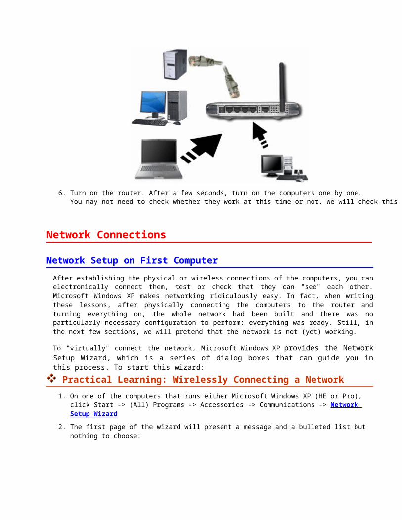
6. Turn on the router. After a few seconds, turn on the computers one by one.You may not need to check whether they work at this time or not. We will check this later
Network Connections
Network Setup on First Computer
After establishing the physical or wireless connections of the computers, you can electronically connect them, test or check that they can "see" each other. Microsoft Windows XP makes networking ridiculously easy. In fact, when writing these lessons, after physically connecting the computers to the router and turning everything on, the whole network had been built and there was no particularly necessary configuration to perform: everything was ready. Still, in the next few sections, we will pretend that the network is not (yet) working.
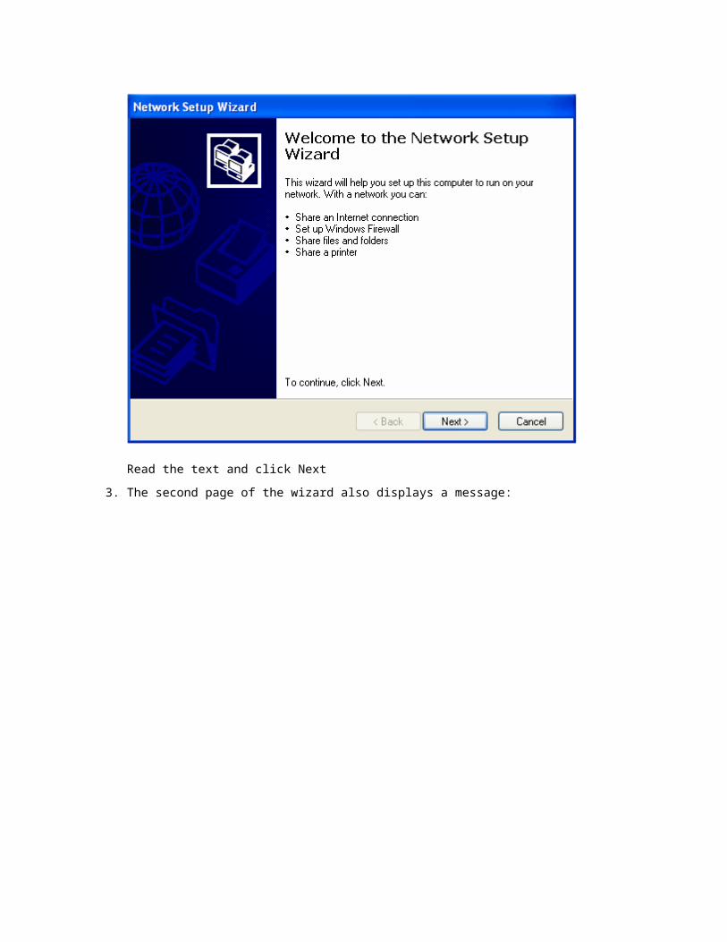
To "virtually" connect the network, Microsoft Windows XP provides the Network Setup Wizard, which is a series of dialog boxes that can guide you in this process. To start this wizard:
Practical Learning: Wirelessly Connecting a Network
1. On one of the computers that runs either Microsoft Windows XP (HE or Pro), click Start -> (All) Programs -> Accessories -> Communications -> Network Setup Wizard
2. The first page of the wizard will present a message and a bulleted list but nothing to choose:
Read the text and click Next
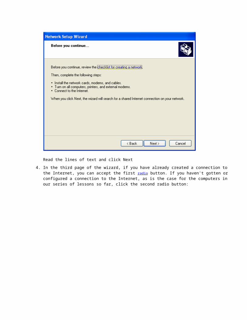
3. The second page of the wizard also displays a message:
Read the lines of text and click Next
4. In the third page of the wizard, if you have already created a connection to the Internet, you can accept the first radio button. If you haven't gotten or configured a connection to the Internet, as is the case for the computers in our series of lessons so far, click the second radio button:
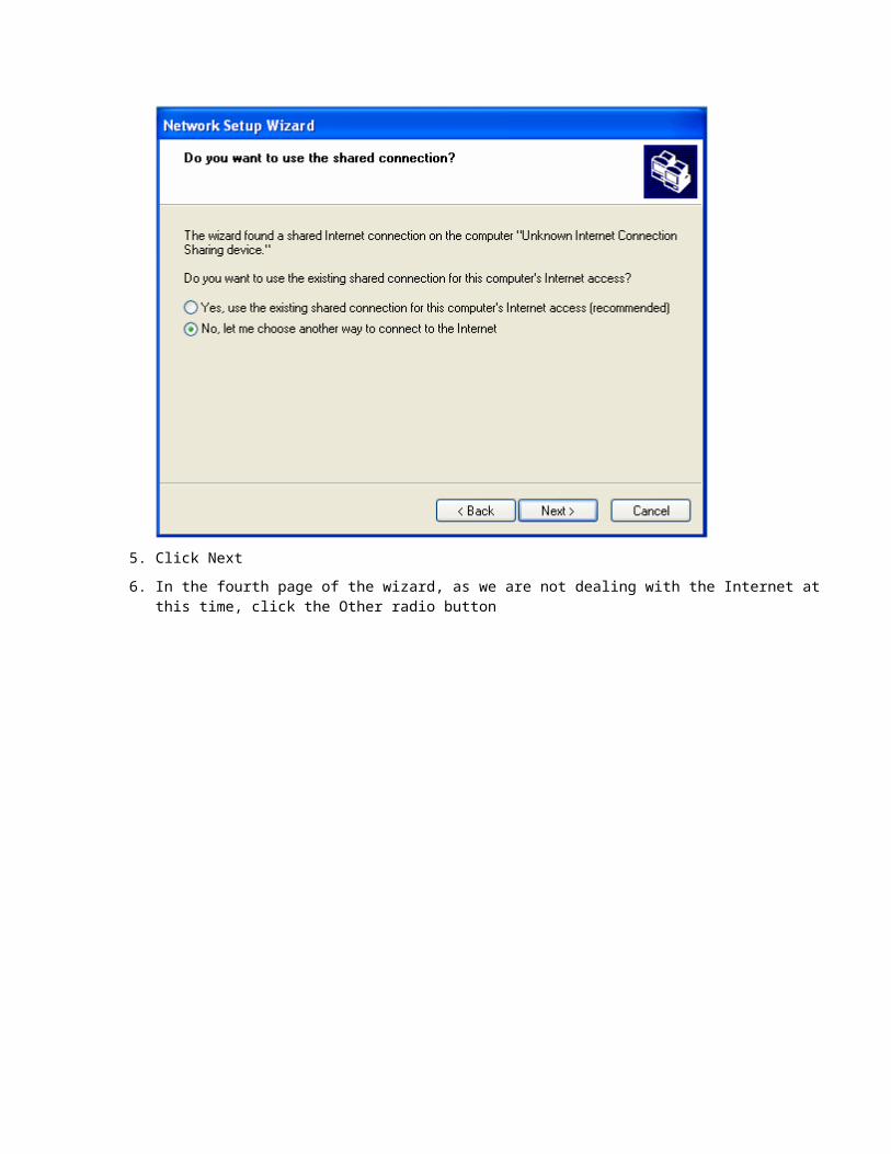
5. Click Next
6. In the fourth page of the wizard, as we are not dealing with the Internet at this time, click the Other radio button
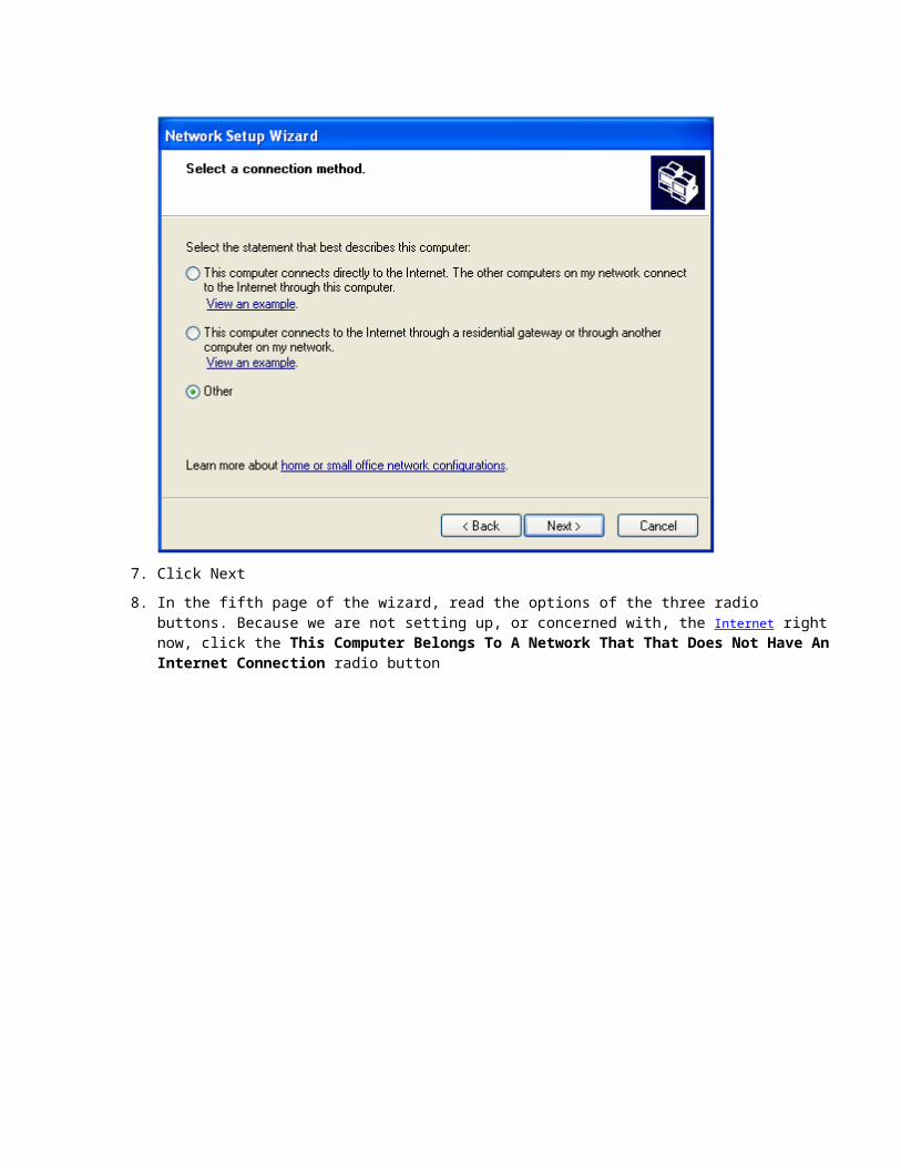
7. Click Next
8. In the fifth page of the wizard, read the options of the three radio buttons. Because we are not setting up, or concerned with, the Internet right now, click the This Computer Belongs To A Network That That Does Not Have An Internet Connection radio button
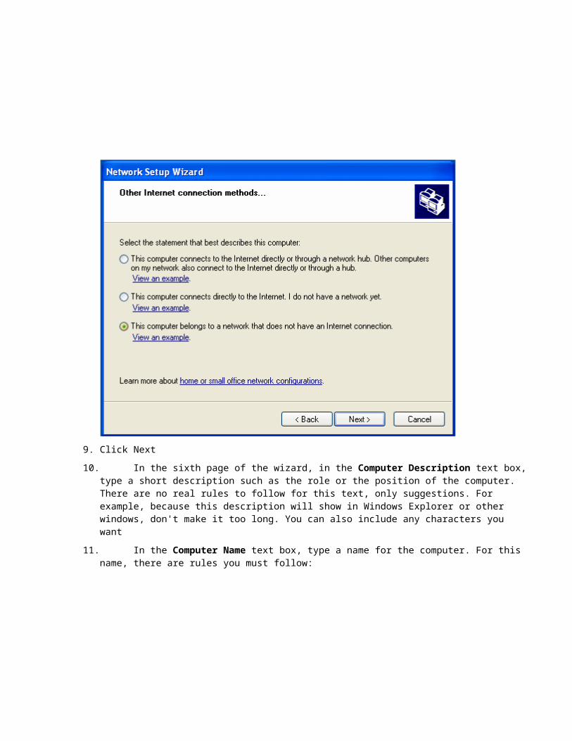
9. Click Next
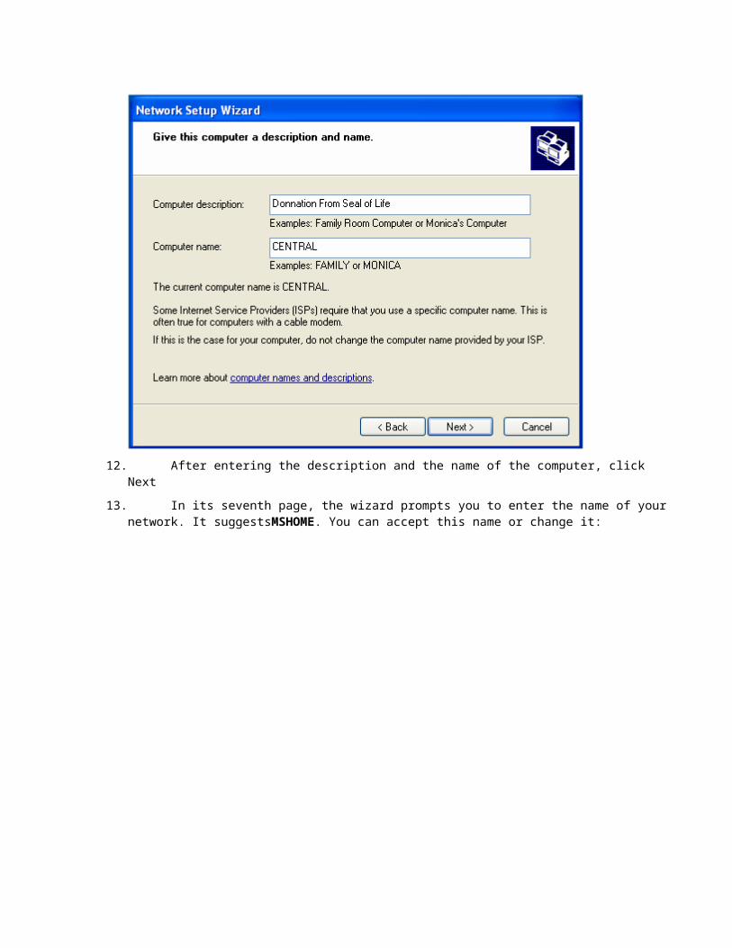
10. In the sixth page of the wizard, in the Computer Description text box, type a short description such as the role or the position of the computer. There are no real rules to follow for this text, only suggestions. For example, because this description will show in Windows Explorer or other windows, don't make it too long. You can also include any characters you want
11. In the Computer Name text box, type a name for the computer. For this name, there are rules you must follow:
12. After entering the description and the name of the computer, click Next
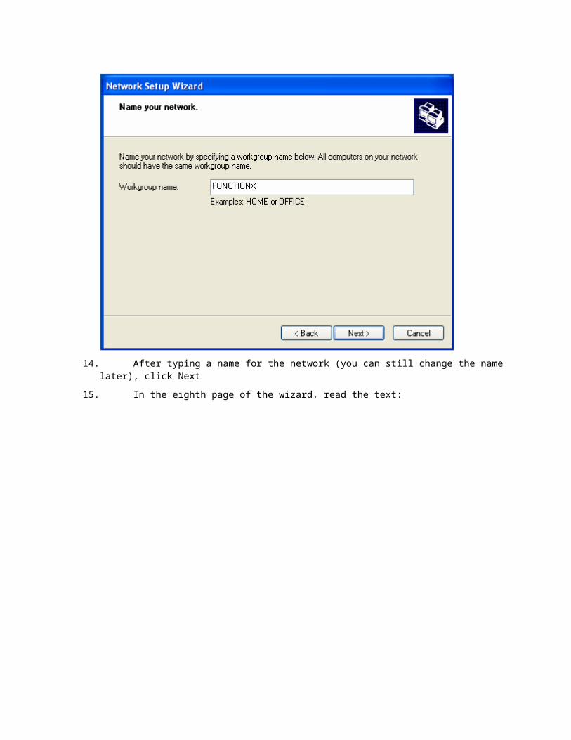
13. In its seventh page, the wizard prompts you to enter the name of your network. It suggestsMSHOME. You can accept this name or change it:
14. After typing a name for the network (you can still change the name later), click Next
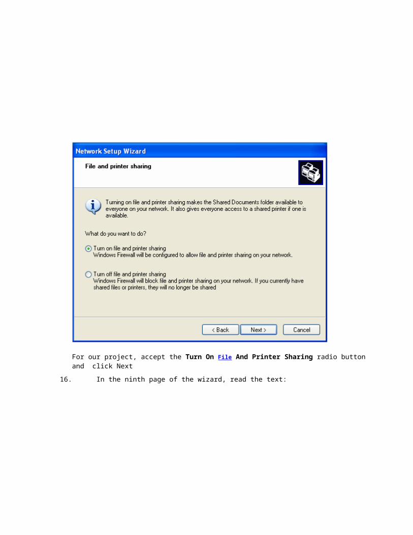
15. In the eighth page of the wizard, read the text:
For our project, accept the Turn On File And Printer Sharing radio button and click Next
16. In the ninth page of the wizard, read the text:
Click Next
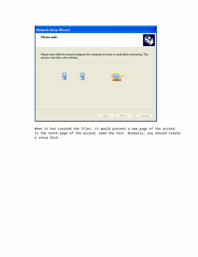
17. After clicking Next, the wizard will start creating the files used to setup a network, based on your previous selections:
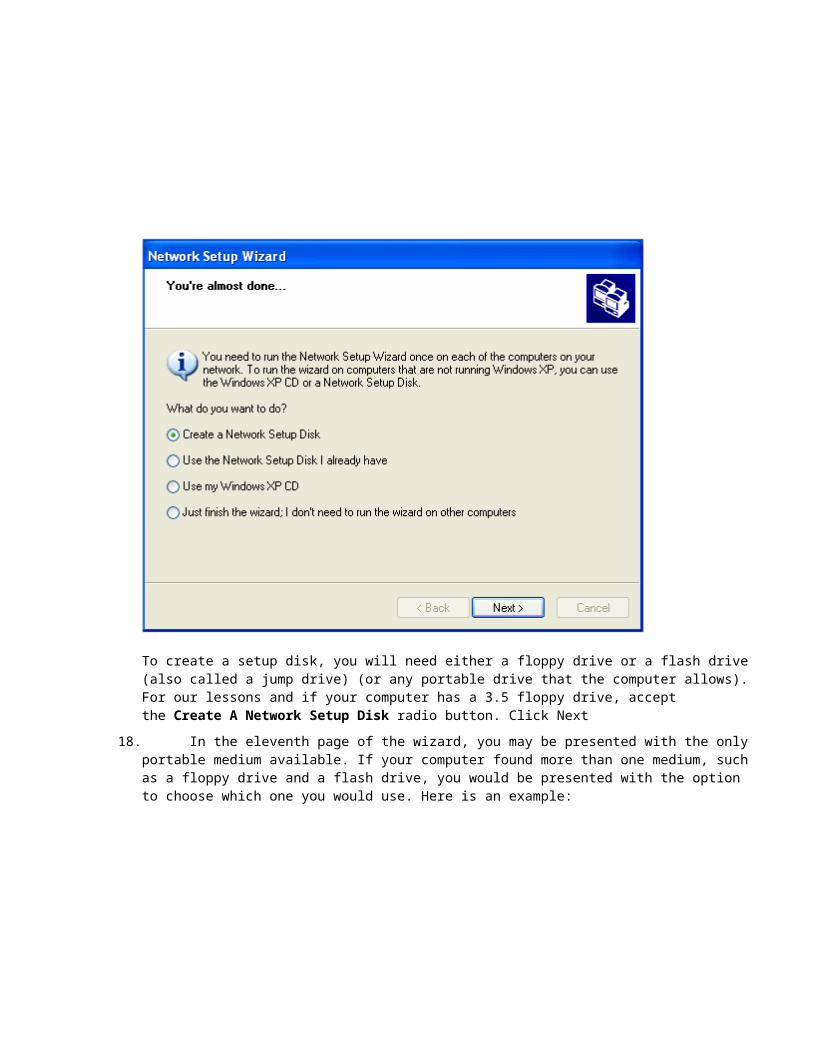
When it has created the files, it would present a new page of the wizard.In the tenth page of the wizard, read the text. Normally, you should create a setup disk:

To create a setup disk, you will need either a floppy drive or a flash drive (also called a jump drive) (or any portable drive that the computer allows).For our lessons and if your computer has a 3.5 floppy drive, accept the Create A Network Setup Disk radio button. Click Next
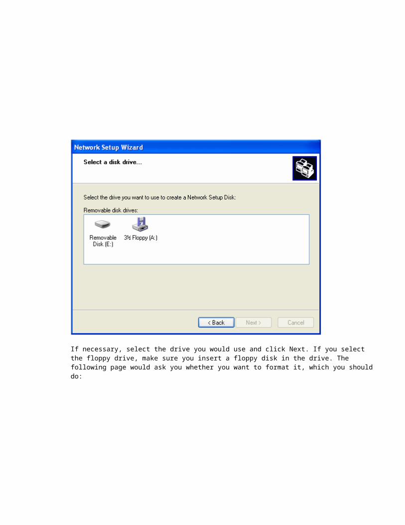
18. In the eleventh page of the wizard, you may be presented with the only portable medium available. If your computer found more than one medium, such as a floppy drive and a flash drive, you would be presented with the option to choose which one you would use. Here is an example:
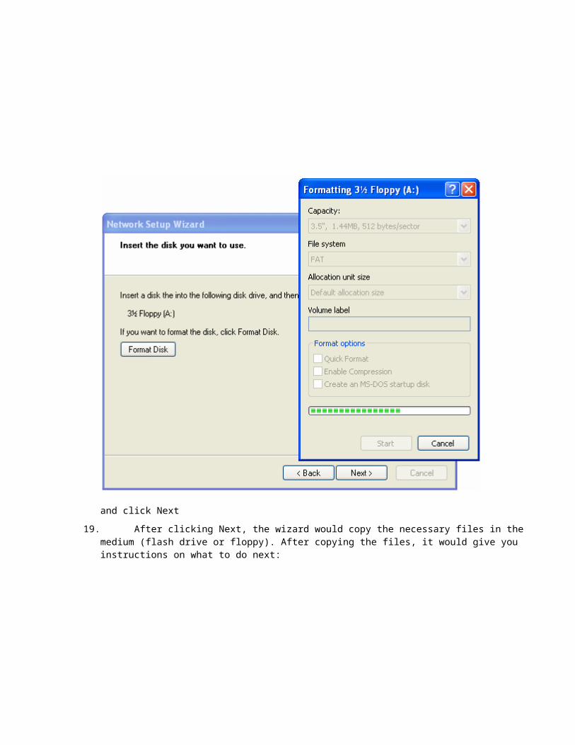
If necessary, select the drive you would use and click Next. If you select the floppy drive, make sure you insert a floppy disk in the drive. The following page would ask you whether you want to format it, which you should do:
and click Next
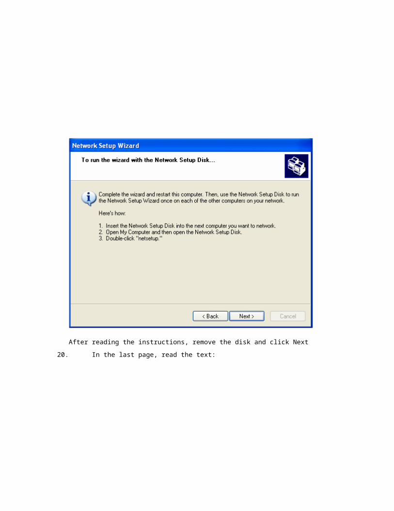
19. After clicking Next, the wizard would copy the necessary files in the medium (flash drive or floppy). After copying the files, it would give you instructions on what to do next:
After reading the instructions, remove the disk and click Next
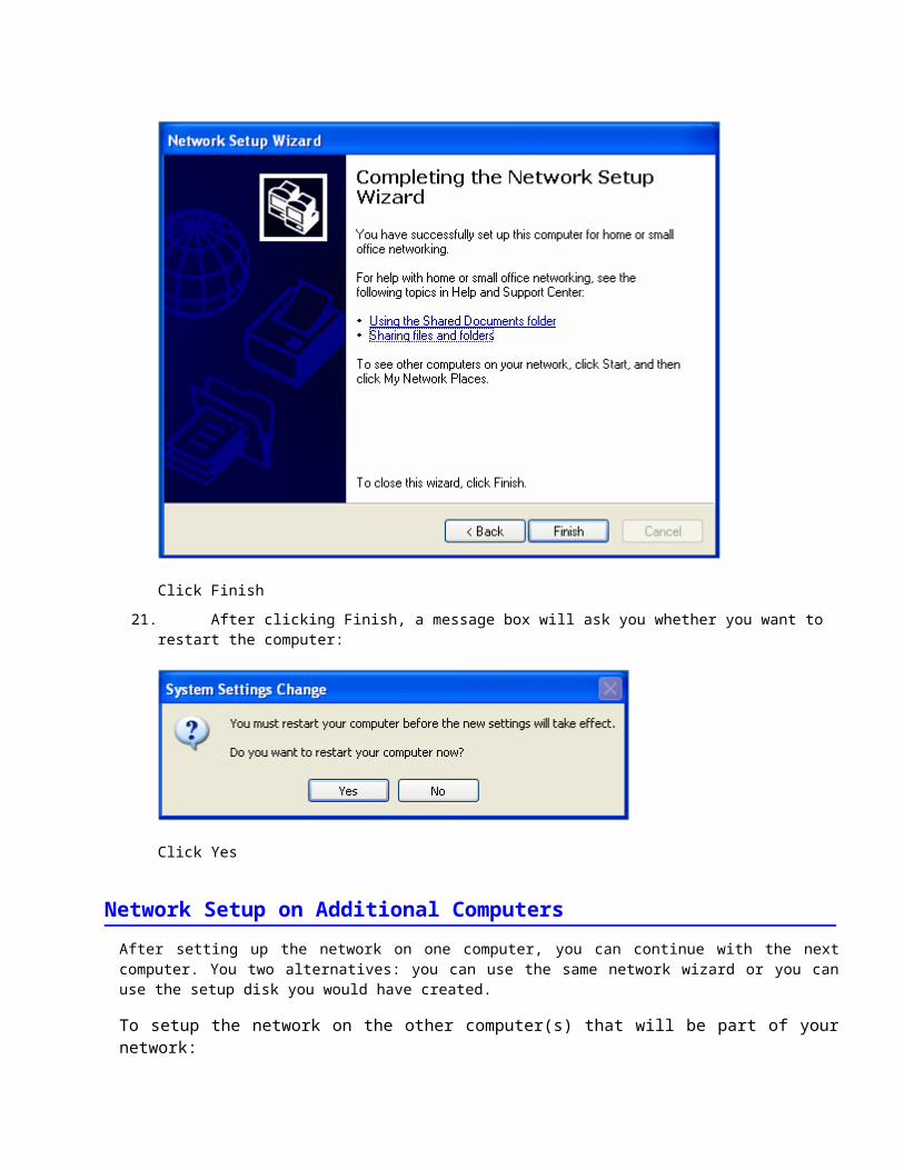
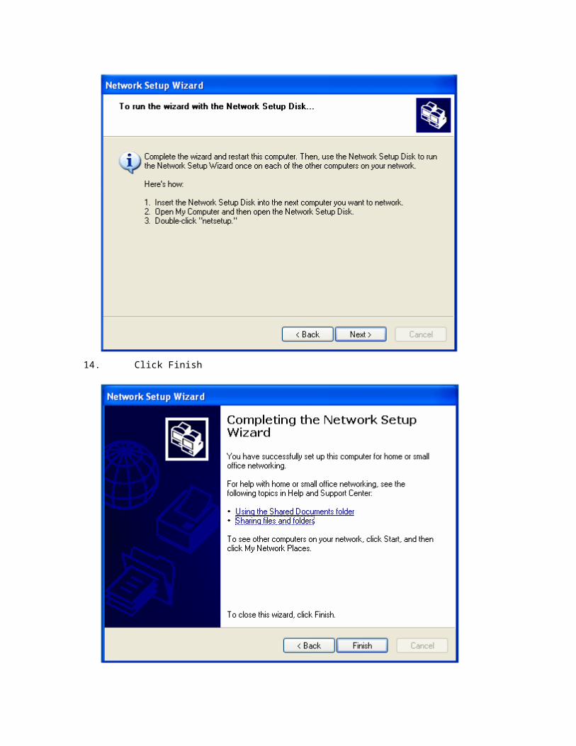
20. In the last page, read the text:
Click Finish
21. After clicking Finish, a message box will ask you whether you want to restart the computer:
Click Yes
Network Setup on Additional Computers
After setting up the network on one computer, you can continue with the next computer. You two alternatives: you can use the same network wizard or you can use the setup disk you would have created.
To setup the network on the other computer(s) that will be part of your network:
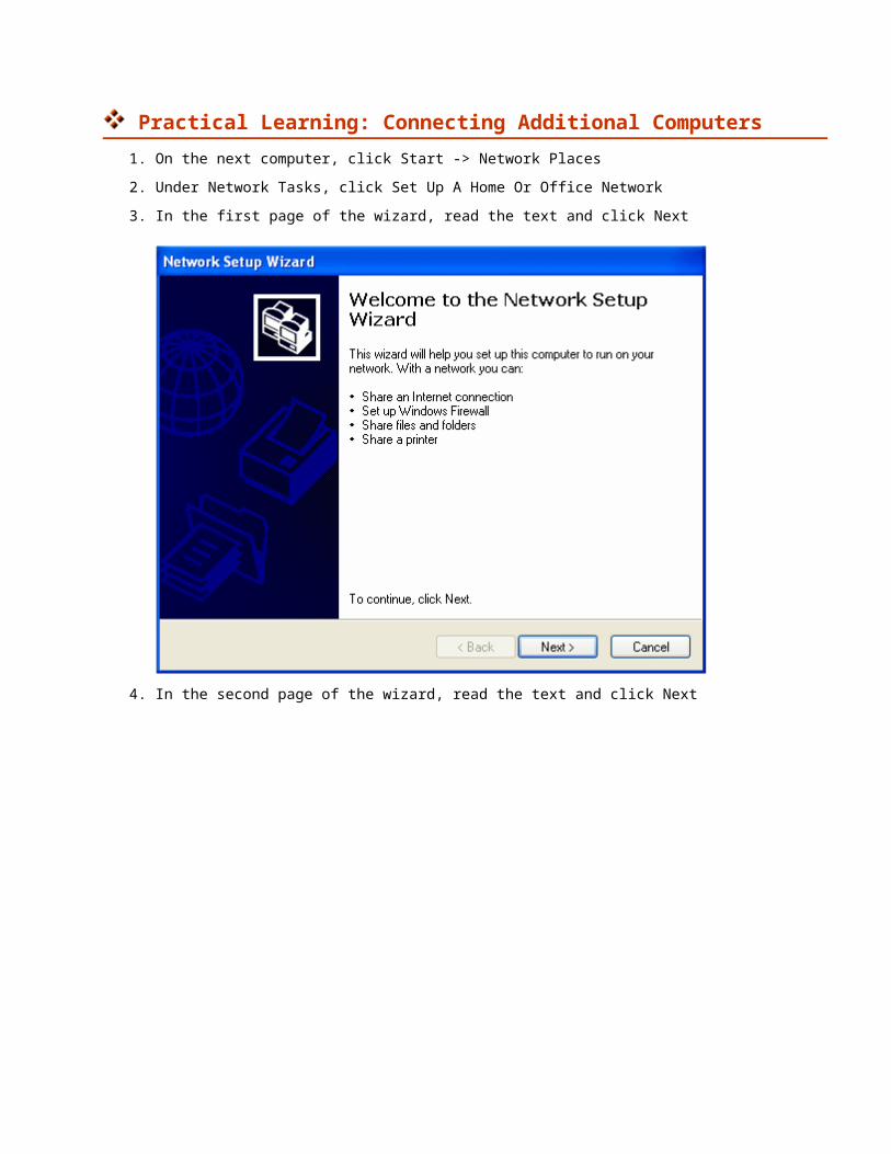
Practical Learning: Connecting Additional Computers
1. On the next computer, click Start -> Network Places
2. Under Network Tasks, click Set Up A Home Or Office Network
3. In the first page of the wizard, read the text and click Next
4. In the second page of the wizard, read the text and click Next
5. In the third page of the wizard, accept the first radio button and click Next
6. In the fourth page of the wizard, in the Computer Description text box, type a short
description that can define or indicate what this computer is used for
7. In the Computer Name text box, type a name that will distinguish this computer in the network. One of the rules you must observe is that the name must be unique in the network. This means that you cannot use the same name you have already given to another computer in the same network:
8. After entering the description and the name of the computer, click Next
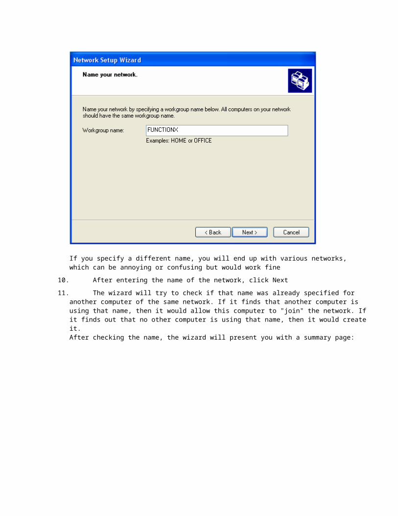
9. In the fifth page of the wizard, it is somewhat important (but it is not a requirement) that you enter the same name you specified for the network of the first computer:

If you specify a different name, you will end up with various networks, which can be annoying or confusing but would work fine
10. After entering the name of the network, click Next
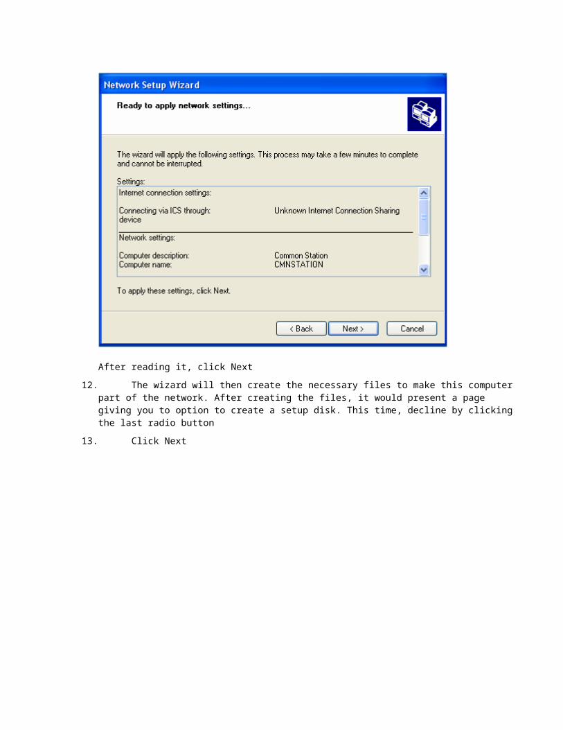
11. The wizard will try to check if that name was already specified for another computer of the same network. If it finds that another computer is using that name, then it would allow this computer to "join" the network. If it finds out that no other computer is using that name, then it would create it.After checking the name, the wizard will present you with a summary page:

After reading it, click Next
12. The wizard will then create the necessary files to make this computer part of the network. After creating the files, it would present a page giving you to option to create a setup disk. This time, decline by clicking the last radio button
13. Click Next

14. Click Finish
15. You will be asked whether you want to restart the computer or not. Click Yes
As an alternative, and as instructed when creating the setup disk:
1. On the other computer, put the setup disk in the drive
2. Using Windows Explorer, My Computer or another file utility or viewer, access the drive that contains the disk you created and double-click the file it contains
3. Follow the instructions on the screen. They are pretty much self-explanatory
4. When asked to restart the computer, do so
Viewing Network Connections
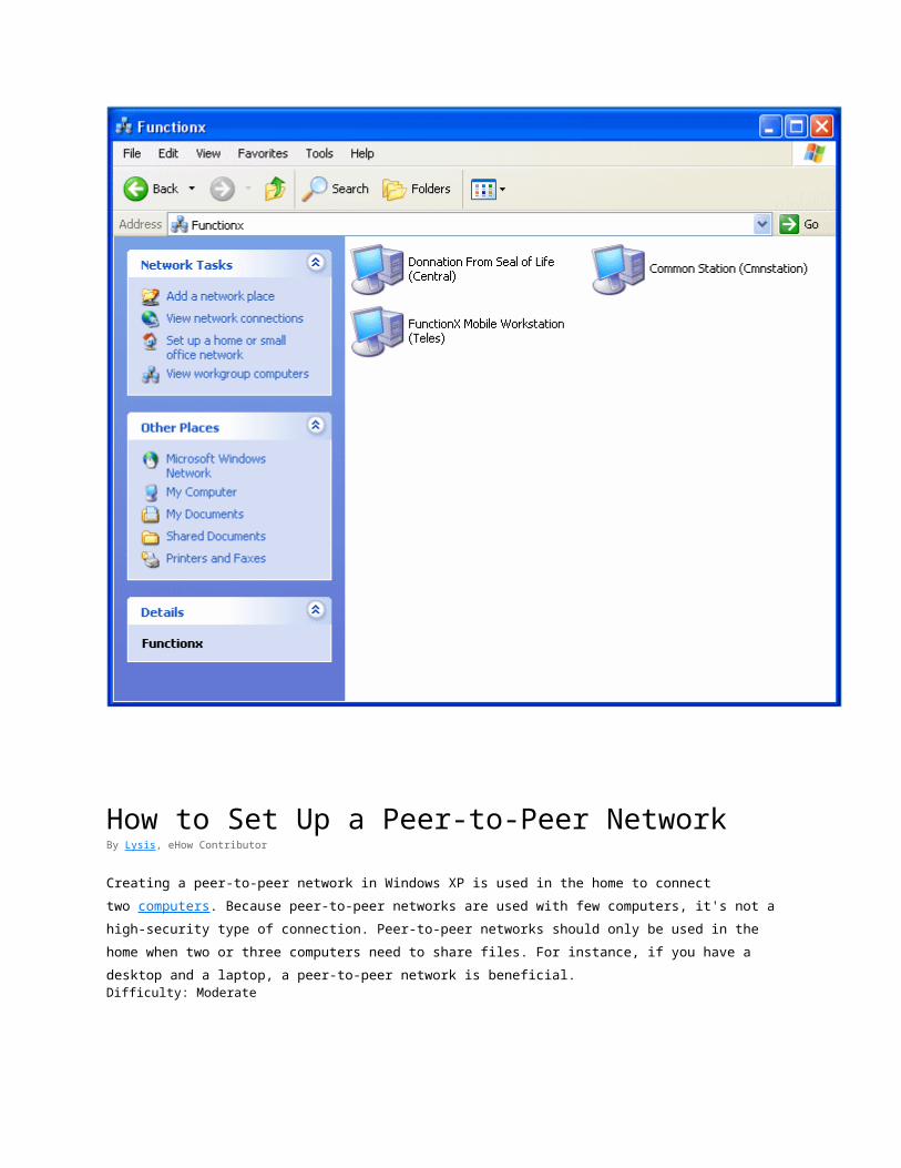
My Network Places
Once you have built a computer network, from time to time, you will need to check what computers are available and/or what files or folders have been shared. To assist you with this, Microsoft Windows XP provides a window named My Network Places.
To view the available connected computers:
Practical Learning: Viewing the Connected Computers
1. On one of the computers, click Start -> My Network Places.If you don't see that option in the right column of the Start menu, depending of your configuration, click Start -> Settings -> Network Connections. Then, under Other Places, click My Network Places.As an alternative, you can click Start -> Control Panel or Start -> Settings -> Control Panel. Under Other Places, click My Network Places.
2. Under Network Tasks, click View Workgroup Computers
How to Set Up a Peer-to-Peer NetworkBy Lysis, eHow Contributor
Creating a peer-to-peer network in Windows XP is used in the home to connect two computers. Because peer-to-
peer networks are used with few computers, it's not a high-security type of connection. Peer-to-peer networks should
only be used in the home when two or three computers need to share files. For instance, if you have a desktop and a
laptop, a peer-to-peer network is beneficial.Difficulty: Moderate
InstructionsThings You'll Need:
1 Ethernet cable for each computer
1. 1
Set the IP addresses of the computers. In Windows XP, the IP addresses are set in the "Network
Connections" folder in the Control Panel. In this folder, right-click the "Local Network" and select
"Properties." The easiest way to assign IP addresses is using the 192.168.0.x format. Replace "x" with
a number from 1 to 254. Each computer needs a different IP address. Set the subnet mask to
255.255.255.0.
2. 2
Attach the cables to the network card of the computer. Connect each cable to the hub. This part of the
setup connects the computers physically. When you browse the network, you should be able to see the
other computer since the IP addresses are in the same range.
3. 3
Right-click a folder to share and select "Sharing." In this screen, select "Share this Folder." You can
also give the folder an alias in the labeled text box. This is the name the other computer displays when
you browse shared folders on the network. Since this is a small, peer-to-peer network, there is no need
to set permissions.
4. 4
Right-click any printers you wish to share and select "Properties." In the properties screen of the
printer, enable sharing. This setting makes printing capable to the printer from one machine to the
other
Read more: How to Set Up a Peer-to-Peer Network | eHow.com http://www.ehow.com/how_5312785_set-up-peertopeer-network.html#ixzz16RkiLRPr
How to Make a Category 5 / Cat 5E Patch Cable
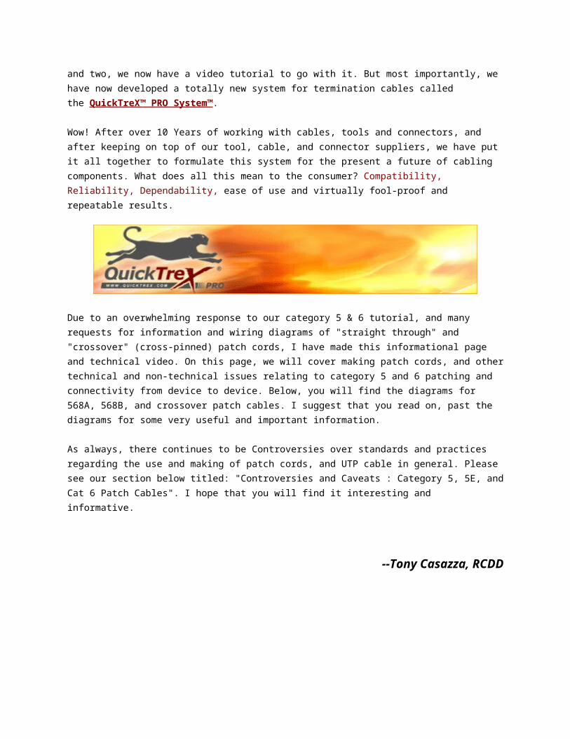
LANshack.com was the very first ecommerce website to offer free online tutorials for cable connections. To say that our articles have been popular over the span of many years would be an understatement. But time marches on and we now have three major updates. For one, we have updated this very popular tutorial, and two, we now have a video tutorial to go with it. But most importantly, we have now developed a totally new system for termination cables called the QuickTreX™
PRO System™.
Wow! After over 10 Years of working with cables, tools and connectors, and after keeping on top of our tool, cable, and connector suppliers, we have put it all together to formulate this system for the present a future of cabling components. What does all this mean to the
consumer? Compatibility, Reliability, Dependability, ease of use and virtually fool-proof and repeatable results.
Due to an overwhelming response to our category 5 & 6 tutorial, and many requests for information and wiring diagrams of "straight through" and "crossover" (cross-pinned) patch cords, I have made this informational page and technical video. On this page, we will cover making patch cords, and other technical and non-technical issues relating to category 5 and 6 patching and connectivity from device to device. Below, you will find the diagrams for 568A, 568B, and crossover patch cables. I suggest that you read on, past the diagrams for some very useful and important information.
As always, there continues to be Controversies over standards and practices regarding the use and making of patch cords, and UTP cable in general. Please see our section below titled: "Controversies and Caveats : Category 5, 5E, and Cat 6 Patch Cables". I hope that you will find it interesting and informative.
--Tony Casazza, RCDD
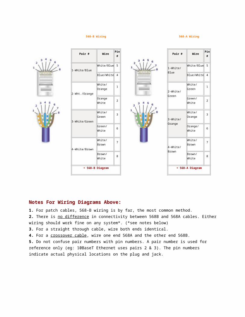
568-B Wiring
Pair # Wire Pin #
1-White/Blue
White/Blue 5
Blue/White 4
2-Wht./Orange
White/Orange 1
Orange White 2
3-White/Green
White/Green 3
Green/White 6
4-White/Brown
White/Brown 7
Brown/White 8
568-A Wiring
Pair # Wire Pin #
1-White/Blue
White/Blue 5
Blue/White 4
2-White/Green
White/Green 1
Green/White 2
3-White/Orange
White/Orange 3
Orange/White 6
4-White/Brown
White/Brown 7
Brown/White 8
< 568-B Diagram < 568-A Diagram
Notes For Wiring Diagrams Above:1. For patch cables, 568-B wiring is by far, the most common method.2. There is no difference in connectivity between 568B and 568A cables. Either wiring should work fine on any system*. (*see notes below)3. For a straight through cable, wire both ends identical.4. For a crossover cable, wire one end 568A and the other end 568B.5. Do not confuse pair numbers with pin numbers. A pair number is used for reference only (eg: 10BaseT Ethernet uses pairs 2 & 3). The pin numbers indicate actual physical locations on the plug and jack.
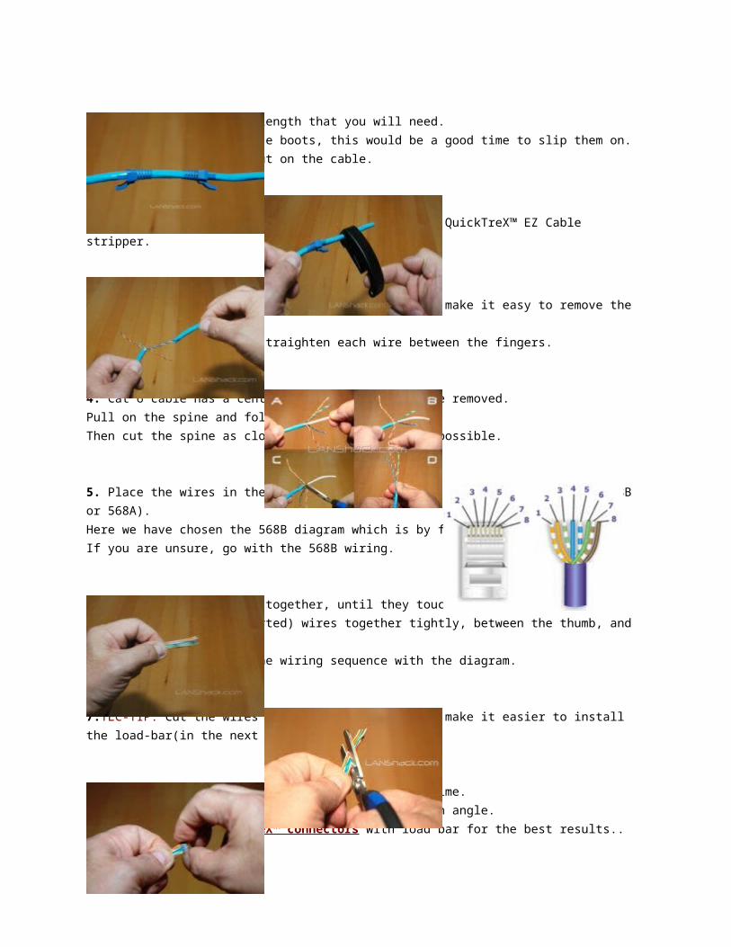
Patch Cable Assembly Instructions
1. Cut the cable to the length that you will need.If you are planning to use boots, this would be a good time to slip them on.Place each boot facing out on the cable.
2. Skin the cable about 1.5down. For fast and dependable skinning we recommend our QuickTreX™ EZ Cable stripper.
3. Remove all of the twists in the cables pairs.TEC-TIP: Use a piece of the removed insulation to make it easy to remove the twists from each pair.Un-twist each pair, and straighten each wire between the fingers.
4. Cat 6 cable has a center spine that needs to be removed.Pull on the spine and fold the pairs back.Then cut the spine as close to the cables end as possible.
5. Place the wires in the order of one of the two diagrams shown above (568B or 568A).Here we have chosen the 568B diagram which is by far the most popular.If you are unsure, go with the 568B wiring.
6.Bring all of the wires together, until they touch.Hold the grouped (and sorted) wires together tightly, between the thumb, and the forefinger.At this point, recheck the wiring sequence with the diagram.
7.TEC-TIP: Cut the wires on a very sharp angle to make it easier to install the load-bar(in the next step).
8.Insert the loadbar on the wires one wire at a time. This is why we recommended cutting the wires on an angle.We recommend our QuickTreX™ connectors with load bar for the best results..
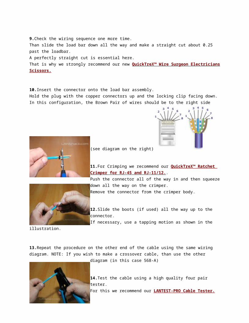
9.Check the wiring sequence one more time.Than slide the load bar down all the way and make a straight cut about 0.25 past the loadbar.A perfectly straight cut is essential here.That is why we strongly recommend our new QuickTreX™ Wire Surgeon Electricians Scissors.
10.Insert the connector onto the load bar assembly.Hold the plug with the copper connectors up and the locking clip facing down.In this configuration, the Brown Pair of wires should be to the right side
(see diagram on the right)
11.For Crimping we recommend our QuickTreX™ Ratchet Crimper for RJ-45 and RJ-11/12..Push the connector all of the way in and then squeeze down all the way on the crimper.Remove the connector from the crimper body.
12.Slide the boots (if used) all the way up to the connector. If necessary, use a tapping motion as shown in the illustration.
13.Repeat the procedure on the other end of the cable using the same wiring diagram. NOTE: If you wish to make a crossover cable, than use the other diagram (in this case 568-A)
14.Test the cable using a high quality four pair tester.

For this we recommend our LANTEST-PRO Cable Tester.
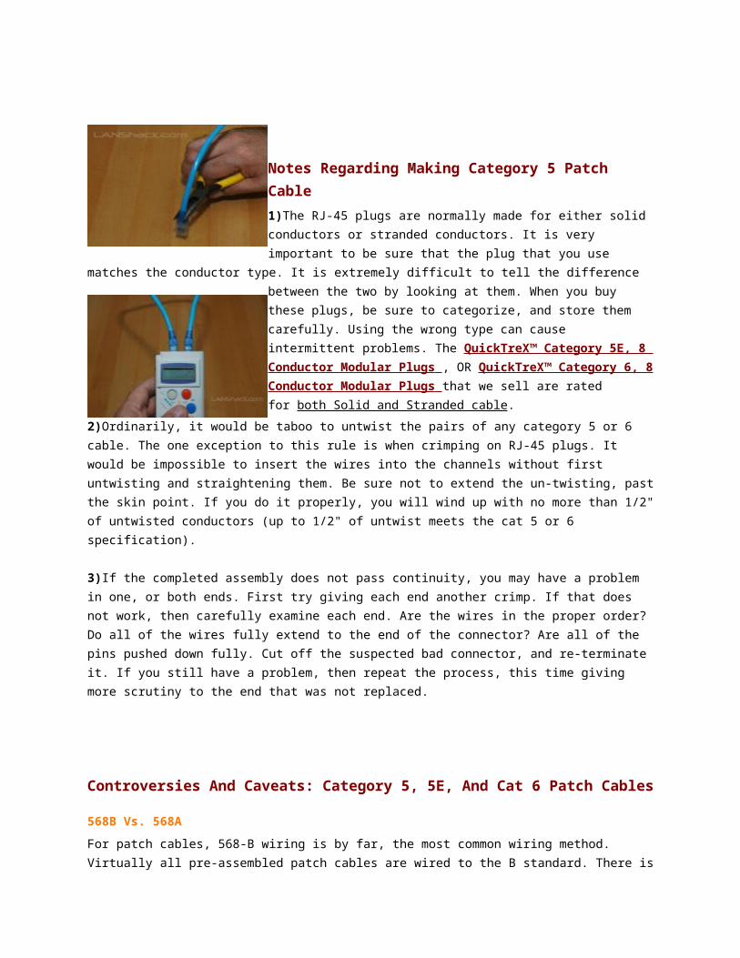
Notes Regarding Making Category 5 Patch Cable1)The RJ-45 plugs are normally made for either solid conductors or stranded conductors. It is very important to be sure that the plug that you use matches the conductor type. It is extremely difficult to tell the difference between the two by looking at them. When you buy these plugs, be sure to categorize, and store them carefully. Using the wrong type can cause intermittent problems. The QuickTreX™ Category 5E, 8 Conductor Modular Plugs , OR QuickTreX™ Category 6, 8 Conductor Modular Plugs that we sell are rated for both Solid and Stranded cable.
2)Ordinarily, it would be taboo to untwist the pairs of any category 5 or 6 cable. The one exception to this rule is when crimping on RJ-45 plugs. It would be impossible to insert the wires into the channels without first untwisting and straightening them. Be sure not to extend the un-twisting, past the skin point. If you do it properly, you will wind up with no more than 1/2" of untwisted conductors (up to 1/2" of untwist meets the cat 5 or 6 specification).
3)If the completed assembly does not pass continuity, you may have a problem in one, or both ends. First try giving each end another crimp. If that does not work, then carefully examine each end. Are the wires in the proper order? Do all of the wires fully extend to the end of the connector? Are all of the pins pushed down fully. Cut off the suspected bad connector, and re-terminate it. If you still have a problem, then repeat the process, this time giving more scrutiny to the end that was not replaced.
Controversies And Caveats: Category 5, 5E, And Cat 6 Patch Cables
568B Vs. 568A
For patch cables, 568-B wiring is by far, the most common wiring method. Virtually all pre-assembled patch cables are wired to the B standard. There is no difference in connectivity between 568B and 568A cables. Therefore, a 568B patch cable should work fine on a 568A cabling system, and visa-versa.
Re-Use Of Old Cables
We have seen this happen time and time again. Perfectly good patch cables that have been working fine for years, get removed from their installation, and re-installed on the same, or different network. The result can be a nightmare. What happens is that the cable, over time, adapts to the way that it is bent in it's original installation. When these cables are removed and re-installed, they can either completely lose their connection, or develop intermittent problems. This is due to stresses that may be opposite to what they were originally subject
to. If the integrity of your network is more valuable than the price of new patch cables, then we strongly suggest that you use brand new cables for all closet cleanups, network moves, etc.
Stranded Vs. Solid Wire
Almost all patch cables that are made have stranded wire. Stranded wire is normally specified for use in patch cables due to its superior flexibility. There has been some talk recently, in the technical sector of the structured wiring community, regarding the possible use of solid conductors for patch cables. The reason for the spotlight on solid wire is that it is supposedly more stable, under a variety of conditions. Please note that we now offer custom Solid copper category 5E patch cables in Plenum insulation in lengths of up to 295 feet. These cables are suitable for use in air handling (Plenum) ceilings and environments.
Featured Product!
QuickTreX™ Wire Surgeon Electricians Scissors
SKU # QC-X9XLMSRP $34.00
Your Price $24.95
Choose Options
Quantity:
QuickTreX™ Wire Surgeon Electricians Scissors
Crafted in Germany of durable ice-tempered Solingen stainless steel that holds up under extreme use.
This wire shear is precision designed for clean cutting and specially ground for use with wire, braiding, etc. Slight serrations on the blade prevent wire slippage and make dependable precise cuts possible.
The ergonomically designed soft rubber handle provides fatigueless use suitable for right or left-handed people.Whether you are a professional or amateur, you will agree that these are the best wire cutting scissors that you have ever used!.
Discounts: (discounted at checkout) 4 or more @ 5% off
Availability: Usually ships within 1 to 2 days.
Urgent Orders: Read Information
We have all the plugs and the boots that you'll need to make your own
cable.
LANshack.com sells all of thevery best tools, testers and toolkitsfor installing and troubleshooting
UTP copper cabling.
We also carryof Fiber Optic
Test Instruments.
Share one Network Cable for two Network Devices: Network Splitter (Pair), Network Splitter Kit (Includes Cables) or Run Voice & Data over one CAT5 Cable: Voice/Data Splitter.
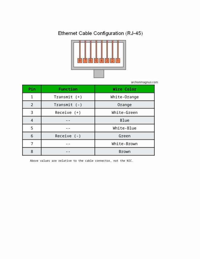
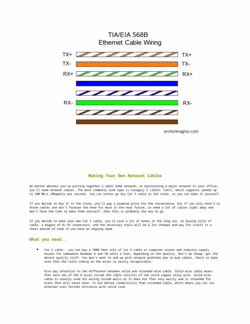
Pin Function Wire Color
1 Transmit (+) White-Orange
2 Transmit (-) Orange
3 Receive (+) White-Green
4 -- Blue
5 -- White-Blue
6 Receive (-) Green
7 -- White-Brown
8 -- Brown
Above values are relative to the cable connector, not the NIC.

Making Your Own Network Cables
No matter whether you're putting together a small home network, or maintaining a major network in your office, you'll need network cables. The most commonly used type is Category 5 (short: Cat5), which supports speeds up to 100 Mb/s (Megabits per second). You can either go buy Cat 5 cable in the store, or you can make it yourself.
If you decide to buy it in the store, you'll pay a premium price for the convenience, but if you only need 2 or three cables and don't foresee the need for more in the near future, or need a lot of cables right away and don't have the time to make them yourself, then this is probably the way to go.
If you decide to make your own Cat 5 cable, you'll save a lot of money in the long run, as buying rolls of cable, a baggie of RJ-45 connectors, and the necessary tools will be a lot cheaper and pay for itself in a short period of time if you have an ongoing need.
What you need...
Cat 5 cable - you can buy a 1000 feet roll of Cat 5 cable at computer stores and industry supply houses for somewhere between 6 and 10 cents a foot, depending on the quality. Don't be cheap, get the decent quality stuff. You don't want to end up with network problems due to bad cables. Check to make sure that the color-coding on the wires is easily recognizable.
Also pay attention to the difference between solid and stranded wire cable. Solid wire cable means that each one of the 8 wires inside the cable consists of one solid copper alloy wire. Solid wire cable is usually used for wiring inside walls as it does not flex very easily and is intended for wires that will never move. It has better conductivity than stranded cable, which means you can run ethernet over farther distances with solid core.
Stranded wire cable means that each one of the 8 wires inside the cable consists of a few dozen very fine hair-like strands that bend and flex very easily. Stranded wire cable is usually used for
making patch cables because of its flexibility (the wires won't break as easily from being moved around and twisted frequently).
RJ-45 connectors - They usually come in bags of 50, 100 etc. and cost less than a quarter each. Pay attention to the type of RJ-45 connector you get and make sure it is intended for the type of Cat5 wire you're using. There are two different kind of RJ-45 connectors, depending on whether you use them with solid or stranded wire cable as mentioned above. Using the wrong kind with the wrong cable will most likely result in a bad connection.
Crimping tool - While this is the expensive part of making your own cables, it's only a one-time startup cost. They run anywhere from 10 to 50 bucks depending on the quality and features. Keep in mind that the crimpers will pay for themselves after you make a few cables. A good crimping tool has a pair of wire cutters built in, as well as a blade to strip insulation. It also might support crimping of other connectors such as RJ-11.
Diagonal Cutter Pliers - You'll need a pair of these to cut the wires in case the crimper doesn't come with a built-in wire cutter.
What type of cable do you want to make? This page: Straight through cables
<< previous page
There are two types of network cables commonly used in PC networks - Straight-through and cross-over.
Cross-over: A cross-over cable is used to connect two computers via their NICs, without using a hub or switch. (Note: You can only connect two computers at one time, connecting three or more will require a hub or switch of some sort).
Straight-through: A straight-through network cable is just what the name implies, a cable that passes data straight through from one end to another. Straight-through cables are used for a variety of connections. (e.g. connecting a computer to a hub or switch, connecting a computer to a cable/ISDN/DSL modem, and linking switches and hubs together.)
Let's start with a straight-through cable and then we'll get fancy with a cross-over cable.
Cutting, Stripping, And Sorting The Wires
Cut a piece of Cat 5 as long as you need. When you cut, remember the old saying: Measure twice, cut once. Make sure the cut on each end is clean and straight.
Strip about an inch of the insulation off the cable. Cut it back nice and square. Some crimping tools such as the one used in this article come with a built-in wire stripper. You put the cable in to a stop on one side of the cutter. It will cut the jacket the right length to make a perfect crimp.
It is extremely important that you only cut the plastic insulation/jacket and not the wire. Damaging one of the 8 wires, even if you just nick it or partially cut it, will ruin your cable.
Untwist the wires. You'll notice that there are 4 pairs of multi-colored wires inside. Sort the pairs by color. You should end up with wires color coded as follows: blue/blue-white, orange/orange-white, green/green-white, brown/brown-white.
Note: Some Cat 5 cable skimps on the color-coding and you will have to keep the track of which wire was wrapped around which. If at all possible, check the cable before you buy and make sure the color-coding is easy to recognize. If not, you'll be cursing up a storm later and wish you would have spent the extra 5 bucks on the better cable.
Now align the wires in the following order from left to right. The order is important since there is a wiring standard defined by the Telecommunications Industry Association (TIA) http://www.tiaonline.org. It's called the EIA/TIA-568 Commercial Building Telecommunications Wiring Standard, and you can find more information on it here:http://www.digital-delivery.com/Standards.htm#s5
WHITEORANGE
ORANGE
WHITEGREEN
BLUE
WHITEBLUE
GREEN
WHITEBROWN
BROWN
Get the wires lined up and nice and straight. Then clip off the top millimeter so that they are all the same length and stick out about half an inch from the insulated part.

Attaching the RJ-45 Connector
<< previous page
The best way to insert the cable into the RJ-45 connector is this:
Hold an RJ-45 connector so that the plastic release clip is facing away from you, and the opening for the wires is pointing down.
While squeezing the cable so that the jacket does not move on the wires, insert the sorted and aligned wires carefully into the RJ-45 connector partway. You'll feel some resistance as the wires enter the grooves in the connector.
Looking at the side of the connector that's facing you (should be the one without the clip), verify that the wires are still in the correct order. Sometimes the act of pushing the wires into the connector can cause the order of the wires to be switched at the last moment. Use a magnifying glass if needed.
Push the wires the remaining way into the connector. Make sure that the wires have gone all the way into the connector and are touching the end of the RJ-45 connector. You should see a line of 8 bare wire ends. If one is missing and that individual wire hasn't gone far enough into the connector, pull the wires out, line up the ends and put them in again. You can't see this problem from the side - you can only see it from the end.
Now push the jacket as far as it will go into the connector.
Getting all of the wires lined up and inserted correctly can be a little tricky, so take your time. This gets easier as you get the feel of it.
If everything went well, it should look like this:
Right:

See how the end of the insulation sits snug inside the RJ-45, and how the wires go all the way to the end?
Below are two examples how it should NOT look. In the example on the left the wires were left too long, which leaves wires unprotected between the RJ-45 and the insulation. In the example on the right, the wires were cut too short and now don't reach far enough to make contact.
Wrong!
Double-check one last time that the wires are aligned correctly and all the way in. Then insert the RJ-45 connector into the
appropriate opening of the crimping tool. Give the handle a nice, tight squeeze without crushing the RJ-45. If you have purchased a pair of ratchet type crimpers you will know that you are done when they release. If you bought a cheap-o pair, check to make sure that all of the little metal contacts are even and at the same height below the plastic of the plug.

Now repeat this entire procedure to put an RJ-45 plug on the other end of the cable. Use the exact same wiring scheme as on the first end, which will make it a straight-through cable.
Note: If you decided to spend a couple extra bucks on the strain relief sleeves, be sure to put them on and facing the correct direction before you crimp the second end.
A cross-over cable
<< previous page
The cross-over cable can be made using the same steps as the straight-through cable. The only difference is the order in which the wires are put into the second connector. On the straight-through cable you use the exact same order of wires. On a cross-over cable you use a different order on each end.
The first end uses the same color scheme as a straight-through cable:
WHITEORANGE
ORANGE
WHITEGREEN
BLUE
WHITEBLUE
GREEN
WHITEBROWN
BROWN
The second end uses the following color scheme:
WHITEG
GREEN
WHITEO
BLUE
WHITEB
ORANGE
WHITEB
BROWN

REEN
RANGE
LUE
ROWN
If you take a close look and compare the two ends, you'll notice how the green and the orange pair trade places, which makes it a cross-over cable.
Note: When you make a cross-over cable, mark it to distinguish it from your straight-through cables. You can put colored tape on it, use a marker, use a different color cable, whatever works for you. If you don't, eventually you'll get it mixed in with your other cables and lose your mind trying to figure out why your connection to the network is hosed.
Test It
Once your cable is finished, you should test it to make sure it works. For $20-30 you can purchase a cable tester. Insert the two ends of the cable into the jacks on the tester and watch the lights. If they all light up, you have a good connection for each wire and the cable checks out.