CableCop 300 Cable detection system - Farnell
24
3.348.736.02 1/2.96 CableCop 300 Cable detection system Operating Instructions GOSSEN METRAWATT CAMILLE BAUER GOSSEN METRAWATT CAMILLE BAUER
Transcript of CableCop 300 Cable detection system - Farnell

3.348.736.021/2.96
CableCop 300Cable detection system
Operating Instructions
GOSSEN
M
ETRA
WATT
CAMILL
E BAUER
GOSSEN
M
ETRA
WATT
CAMILL
E BAUER

2 GOSSEN-METRAWATT
Safety notes
Caution!!Before you use the cable detection system CableCop 300, carefully read these op-erating instructions and follow the generally relevant safety specifications according to DIN VDE while operating the system.When properly used, the safety of both the unit and the user is ensured. Their safety is not ensured, however, if the unit is misused or carelessly handled
Before you use an electrical device, always make a performance test to verify that the de-vice is operating properly.
Preferrably connect the signal generator S330 between phase and neutral. Before you connect the signal generator between phase and neutral, absolutely check the ground re-sistance according to DIN VDE 0100. With incorrect grounding, all parts connected to ground could carry voltage should there be a fault.
Prior to connecting the signal generator S330 to current or voltage circuits, check that the maximum permissible voltage for the signal generator is not exceeded.
Prior to connecting the transmitter T320, verify that the circuits or lines to be tested do not carry current or voltage.
Avoid direct contact with non-insulated live lines. Eventually wear suitable insulating gloves as well as goggles.
Disconnect the transmitter T320 from the measuring circuit before you replace the bat-tery.
GOSSEN-METRAWATT 3
ContentsPage
1 Applications, function principle . . . . . . . . . . . . . . . . . . . . . . . . . . . . . . . . . . . . . . . . . . 4
2 Description of the units . . . . . . . . . . . . . . . . . . . . . . . . . . . . . . . . . . . . . . . . . . . . . . . . 52.1 Receiver R300 . . . . . . . . . . . . . . . . . . . . . . . . . . . . . . . . . . . . . . . . . . . . . . . . . . . . . . . . . . . . . . . 52.2 Signal generator S330 for live lines . . . . . . . . . . . . . . . . . . . . . . . . . . . . . . . . . . . . . . . . . . . . . . . . 62.3 Transmitter T320 for electrically dead circuits . . . . . . . . . . . . . . . . . . . . . . . . . . . . . . . . . . . . . . . . . 7
3 Measurements on live lines with the signal generator S330 . . . . . . . . . . . . . . . . . . . . 83.1 Closed circuit mode . . . . . . . . . . . . . . . . . . . . . . . . . . . . . . . . . . . . . . . . . . . . . . . . . . . . . . . . . . . . 83.2 General procedures for live lines . . . . . . . . . . . . . . . . . . . . . . . . . . . . . . . . . . . . . . . . . . . . . . . . . . . 93.3 Locating switches, e.g. in building installations . . . . . . . . . . . . . . . . . . . . . . . . . . . . . . . . . . . . . . . 103.4 Locating lines in ceilings, walls and floors . . . . . . . . . . . . . . . . . . . . . . . . . . . . . . . . . . . . . . . . . . . 103.5 Locating short circuits between phase and protective conductor starting from a switchboard . . . . . . 113.6 Locating ground faults in three-phase systems . . . . . . . . . . . . . . . . . . . . . . . . . . . . . . . . . . . . . . . 123.7 Locating buried lines or underground cables up to a depth of approx. 3 m . . . . . . . . . . . . . . . . . . . 133.8 Tracing lines in conduits . . . . . . . . . . . . . . . . . . . . . . . . . . . . . . . . . . . . . . . . . . . . . . . . . . . . . . . 143.9 Tracing coaxial cables . . . . . . . . . . . . . . . . . . . . . . . . . . . . . . . . . . . . . . . . . . . . . . . . . . . . . . . . . 15
4 Measurements on electrically dead lines with the transmitter T320 . . . . . . . . . . . . . 164.1 Open circuit mode . . . . . . . . . . . . . . . . . . . . . . . . . . . . . . . . . . . . . . . . . . . . . . . . . . . . . . . . . . . . 164.2 General procedures for electrically dead lines . . . . . . . . . . . . . . . . . . . . . . . . . . . . . . . . . . . . . . . . 164.3 Locating lines and line interruptions in ceilings, walls and floors . . . . . . . . . . . . . . . . . . . . . . . . . . . 174.4 Tracing the entire building installation . . . . . . . . . . . . . . . . . . . . . . . . . . . . . . . . . . . . . . . . . . . . . . 184.5 Tracing water and heating pipe lines and conduits . . . . . . . . . . . . . . . . . . . . . . . . . . . . . . . . . . . . . 184.6 Tracing socket outlets and switches within the building installation . . . . . . . . . . . . . . . . . . . . . . . . . 194.7 Tracing bottlenecks in tubing or conduits . . . . . . . . . . . . . . . . . . . . . . . . . . . . . . . . . . . . . . . . . . . 204.8 Locating faults on an electric floor heating system . . . . . . . . . . . . . . . . . . . . . . . . . . . . . . . . . . . . . 214.9 Locating underground lines (also in the case of a broken cable) . . . . . . . . . . . . . . . . . . . . . . . . . . . 22
5 Technical Data . . . . . . . . . . . . . . . . . . . . . . . . . . . . . . . . . . . . . . . . . . . . . . . . . . . . . . 235.1 General information . . . . . . . . . . . . . . . . . . . . . . . . . . . . . . . . . . . . . . . . . . . . . . . . . . . . . . . . . . . 235.2 Receiver R300 . . . . . . . . . . . . . . . . . . . . . . . . . . . . . . . . . . . . . . . . . . . . . . . . . . . . . . . . . . . . . . 235.3 Signal generator S330 . . . . . . . . . . . . . . . . . . . . . . . . . . . . . . . . . . . . . . . . . . . . . . . . . . . . . . . . . 235.4 Transmitter T320 . . . . . . . . . . . . . . . . . . . . . . . . . . . . . . . . . . . . . . . . . . . . . . . . . . . . . . . . . . . . 23
6 Maintenance . . . . . . . . . . . . . . . . . . . . . . . . . . . . . . . . . . . . . . . . . . . . . . . . . . . . . . . 246.1 Battery . . . . . . . . . . . . . . . . . . . . . . . . . . . . . . . . . . . . . . . . . . . . . . . . . . . . . . . . . . . . . . . . . . . . 246.2 Fuse link . . . . . . . . . . . . . . . . . . . . . . . . . . . . . . . . . . . . . . . . . . . . . . . . . . . . . . . . . . . . . . . . . . . 24
7 Repair and replacement parts service . . . . . . . . . . . . . . . . . . . . . . . . . . . . . . . . . . . . 24

4 GOSSEN-METRAWATT
1 Applications, function principle
The cable detection system CableCop 300 permits both electrically dead and live lines in cir-cuits up to 300 V to be reliably detected. An interruption of the power supply, or a discon-necton of equipment containing sensitive electronic parts, is not required. In particular, the following applications are possible:
• Location of lines in ceilings, walls and floors
• Location of line interruptions, switches and fuses
• Location of short circuits
• Location of earth faults in three-phase systems
• Detection of bottlenecks in conduits
• Tracing of underground cables that are buried in the ground up to a depth of 3 m
• Tracing of conduits, water and heating pipe lines
• Sorting of installed lines
The cable detection system consists of a signal generator for live lines and a transmitter for electrically dead lines as well as a receiver.
Signal generator and transmitter feed high-frequency electromagnetic signals into the line to be tested. Along the line, these signals are converted into acoustical and optical signals by the receiver. The signal strength is a measure for the location of the line.
Two basic operating modes are to be distinguished hereby:
Closed-circuit mode :
In this mode, live lines are tested with a potential of a maximum of 300 V to ground.
The signal current of the signal generator, for example, is fed into the phase of the line to be tested and flows back to the signal generator through neutral conductor across the trans-former. This "two-pole" application corresponds to a closed circuit, whereby the energy for the generation of the signals is directly derived from the system.In the case of a shorted line, the current flow in the circuit to be measured is interrupted, a 9-V battery can, for example, be connected into the measuring circuit as a substitute power supply.The receiver evaluates the magnetic component of the signal.
Open-circuit mode :
In this operating mode, only electrically dead lines may be tested.
One output of the transmitter is connected to the line to be tested, the second output to ground. This "single-pole" application corresponds to the principle of a radio transmitter. The connected line hereby becomes the antenna of the transmitter, the ground serves as refer-ence potential. The energy for the generation of the signals is provided by the internal bat-tery.The receiver evaluates the electrical component of the signal.

GOSSEN-METRAWATT 5
2 Description of the units
2.1 Receiver R300
The receiver R300 has two built-in detectors which receive the different signals from the sig-nal generator for live and electrically dead lines.
These signals are indicated both optically and acoustically:
– Optically by a diode assembly with which up to 10 diodes light as a function of the signal strength. A red filter permits reading also in the case of direct incidence of sunlight.
– Acoustically by a sound generator.
GOSSEN
M
ETRA
WATT
CAMILL
E BAUER
GOSSEN
M
ETRA
WATT
CAMILL
E BAUER
RECEIVEREMPFÄNGER
R300
OFFx1x10x100
!OFF
10•8•6•4•2•
2
5
1
4
3
7
61 Mode selector switch
– Open: for transmitter T320– Closed: for signal generator S330
or for locating broken lines2 Thumb wheel
– ON/OFF switch– Vernier sensitivity setting– Stop position highest sensitivity
3 Standby LEDLights provided the battery is inserted and charged
4 Range selector switch for coarse sensitivity setting, amplification: 1, 10 or 100
5 Diode assembly for indication of the signal strength
6 Detectors7 Battery compartment
The battery must be inserted with correctpolarity or else the compartment cannot be closed.

6 GOSSEN-METRAWATT
2.2 Signal generator S330 for live lines
The signal generator S330 sends high-frequency electromagnetic signals which the sensor R300 can locate along the line to be tested. For this purpose, the signal generator must be connected to this line as well as to a return line. The signal generator is designed for lines having AC or DC voltages from 9 to 300 V.
The signal power of this unit can be switched to a lower power so that circuits protected by residual-current circuit breakers can also be connected.
GOSSEN
M
ETRA
WATT
CAMILL
E BAUER
GOSSEN
M
ETRA
WATT
CAMILL
E BAUER
SIGNALGENERATOR
S330
F 250mA 380V
max. 300V
9 - 300 V!
1
2
4
3
1 Standby LEDLights when the line is live
2 Power selector switch– Switch set to the top position: high power– Switch set to the bottom position: low power
3 Battery compartmentWhen withdrawn, the signal generator isdisconnected from the connected circuit
4 Sockets for test leads

GOSSEN-METRAWATT 7
2.3 Transmitter T320 for electrically dead circuits
The transmitter T320 sends high-frequency electromagnetic signals the electric or magnetic component of which can be detected along the line to be tested by the sensor R300. For this purpose, one socket of the transmitter must be connected to this line. The second socket must be connected to ground.
The unit requires a 9-V battery for the power supply.
An additional, external power source, e.g. a 24-V NiCd storage battery, leads to a increase in performance.Storage batteries in the battery compartment are not charged via the external power source.
Caution!!The transmitter can only be used for electrically dead lines.When using power supplies to increase the performance, only power supplies with safe electrical isolation must be used.
GOSSEN
M
ETRA
WATT
CAMILL
E BAUER
GOSSEN
M
ETRA
WATT
CAMILL
E BAUER
TRANSMITTERSENDER
T320
NUR FÜR SPAN-NUNGSLOSESTROMKREISE!UNENERGIZEDCIRCUITS ONLY!
F 2A 250V
OFFON
!
1 ON/OFF switch2 Standby LED
Lights provided a battery is inserted and charged
3 Power selector switch, three-stage4 Battery compartment
When withdrawn, the transmitter isdisconnected from the connected circuit
5 Sockets for test leads6 Battery compartment
The battery must be inserted with correct polarity or else the compartment cannot be closed
7 Socket for external voltage supply for anincrease in performance
2
3
1
4
7
5
6

8 GOSSEN-METRAWATT
3 Measurements on live lines with the signal generator S330
3.1 Closed-circuit mode
In this operating mode, live lines are tested with a potential having a maximum of 300 V to ground.
The load current normally flows in the phase in opposite direction to the neutral conductor, see connection A. This way, the also opposite magnetic fields are weakened, causing a loss in signal strength in the receiver. The depth of detection is reduced. The same applies when the current flows back across the protective conductor, see connection B.
This effect is eliminated by separating the current paths. While one socket is connected to the line to be tested, the return line should not lie within the same cable or cable channel. As a solution, apply the return line to a remote socket outlet via a cable-reel, the other one to a separate ground such as, for example, central heating, water pipe line or sprinkler system.
A B
A B

GOSSEN-METRAWATT 9
3.2 General procedure for live lines
Signal generator If the measuring circuit has no residual-current circuit breaker, select the highest signal
amplification.
Caution!!Before you connect the signal generator to live lines, verify that not more than 300 V DC or AC voltage are applied.
Connect the sockets of the signal generator in line with the application at a time. The diode of the signal generator must always light after connection of the test leads, other-wise the measuring circuit is not closed and no current flows.
Receiver Insert the battery. Select the closed circuit mode. First set the range selector switch 4 to the lowest amplification x1. Switch the unit on by means of the thumb wheel 1 and set the vernier sensitivity to
stage 5. The standby LED must light.
NoteThe sensitivity should generally be chosen in such a way that as much as possible a medium range of the diode assembly is controlled for measured signals (diodes 4 to 6 light). With control up to the tenth diode, signal fluctuations can no longer be val-uated unambigously.
Alignment of the receiver when using the signal generator S330The test head must be held vertical to the line as the electro-magnetic component is to be captured when measuring on closed circuits. Here, the direction of the current is shown by arrows in the con-ductor and the spreading direction of the electromagnetic com-ponent by circular arrows.

10 GOSSEN-METRAWATT
3.3 Locating switches, e.g. in a building installation
Connection: Connect one socket of the signal generator to the neutral conductor, the other one to the phase of the same socket outlet.
Locating: Hold the head of the receiver to every switch in the fuse box.The associated switch is located by the strongest signal.
3.4 Locating lines in ceilings, walls and floors Connection: Connect one socket of the signal generator to a separate ground, the
other one to the phase of the same socket outlet. Locating: Move the head of the receiver in vertical direction along the point at which
you expect the line.

GOSSEN-METRAWATT 11
3.5 Locating short circuits between phase and protective conductor starting from a switchboard
Caution!!Since voltage could be applied to the lines to be tested, act very carefully:– First find out, whether voltage is applied in spite of the short circuit.– When testing the voltage with the aid of the standby LED of the signal generator,
you always should connect the ground first.– Only when there is no voltage applied:
Connect the signal generator and the auxiliary voltage source.
Connection: Connect one socket of the signal generator to ground, the second socket to the phase via an auxiliary voltage source, e.g. a battery of at least 9 V. A precondition for this is that the protective conductor of the building installation is also grounded. Alternatively, one of the test leads can be connected directly to the protective conductor of the building in-stallation instead of to ground.
Locating: Move the head of the receiver in vertical position along the point at which you expect the line. Follow the signal up to the point of the short circuit. Here, the signal disappears as the signal current flows back to the signal generator across the short circuit.
9 V

12 GOSSEN-METRAWATT
3.6 Locating ground faults in three-phase systems
Caution!!Since voltage may be applied to the lines to be tested, act very carefully:– First find out whether voltage is applied in spite of the short circuit.– When testing the voltage with the aid of the standby LED of the signal generator,
you always should connect the ground first.– Only when there is no voltage applied:
Connect the signal generator and the auxiliary voltage source.
Getting started: First test the voltages of the individual phases to ground. The phase hav-ing the lowest voltage probably has a ground fault.
Connection: Connect the socket of the signal generator to a grounded AC or DC power source, the other one to the faulty phase.
Locating: Move the head of the receiver in a vertical position along the point at which you suspect the line. Follow the signal up to the point of the ground fault. From here on, the signal gets weaker as the main portion of the signal current flows back to the signal generator across the ground fault.
e.g. 220 V~

GOSSEN-METRAWATT 13
3.7 Locating of buried lines or underground cables up to a depth of approximately 3 m Connection: Connect the socket of the signal generator to a separate ground, e.g. di-
rectly to an auxiliary earth electrode, the other one to the phase of the line running underground.In the case of an electrically dead cable, a DC or AC source can be con-nected between socket and separate ground.
Signal generator: Switch the signal generator on and select the highest power. Receiver: When searching for a line, proceed as described under "General proce-
dures for live lines" on page 9.
The soil has a minor influence on the generated magnetic field. The signal portion returning via the limitedly conducting earth causes a weakening of the total signal strength to be measured. The signal strength generally depends upon the horizontal position, the depth of the cable, the conductivity of the soil as well as the type of soil.
Instead of a separate earth, a return line running above ground can be used, e.g. a cable-reel. This way, the signal strength can rise by half.
NoteWhen using a separate above-ground return line, note that the distance between forward and return line must be greater than the depth of the underground cable, but at least 2 m.

14 GOSSEN-METRAWATT
3.8 Tracing lines in conduits
NoteNote that the magnetic field on the line to be tested can also influence neighbouring conduits. That is why the receiver should be held at least 2 m away from the next switch box.Conduits of steel having thick walls attenuate the signal to be traced while conduits of plastics or aluminium do not impair the signal.
Connection: Connect one socket of the signal generator to a separate earth, the other one to a live line.
Locating: When searching for a line, proceed as described under "General proce-dures for live lines" on page 9.
GOSSEN-METRAWATT 15
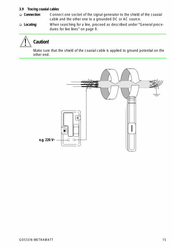
3.9 Tracing coaxial cables Connection: Connect one socket of the signal generator to the shield of the coaxial
cable and the other one to a grounded DC or AC source. Locating: When searching for a line, proceed as described under "General proce-
dures for live lines" on page 9.
Caution!!Make sure that the shield of the coaxial cable is applied to ground potential on the other end.
e.g. 220 V~

16 GOSSEN-METRAWATT
4 Measuring on electrically dead lines with the transmitter T320
4.1 Open circuit mode
Only lines carrying no current and no voltage must be tested in this operating mode.
Connect one output of the transmitter to the line to be tested, the second output to ground.
4.2 General procedures for electrically dead lines
Transmitter Install the battery. Select a medium signal amplification. Switch the transmitter on. The standby LED must light.
Caution!! Make sure that the line to be measured is electrically dead.
Connect the sockets of the transmitter in line with the application at a time.
Receiver Install the battery. Select the open circuit mode. At first set the range selector switch 4 to the lowest amplification x1. Switch the unit on via the thumb wheel 1 and set the vernier sensitivity to stage 5.
The standby LED must light.
NoteThe sensitivity should generally be chosen in such a way that for the signals meas-ured a medium range of the diode assembly is controlled (diodes 4 and 6 light). With control up to the tenth diode, signal variations can no longer be valuated unambig-ously.
GOSSEN-METRAWATT 17
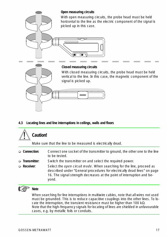
4.3 Locating lines and line interruptions in ceilings, walls and floors
Caution!!Make sure that the line to be measured is electrically dead.
Connection: Connect one socket of the transmitter to ground, the other one to the line to be tested.
Transmitter: Switch the transmitter on and select the required power. Receiver: Select the open circuit mode. When searching for the line, proceed as
described under "General procedures for electrically dead lines" on page 16. The signal strength decreases at the point of interruption and be-yond.
NoteWhen searching for line interruptions in multiwire cables, note that all wires not used must be grounded. This is to reduce capacitive couplings into the other lines. To lo-cate the interruption, the transient resistance must be higher than 100 kΩ. Note that the high-frequency signals for locating of lines are shielded in unfavourable cases, e.g. by metallic foils or conduits.
Open measuring circuitsWith open measuring circuits, the probe head must be held horizontal to the line as the electric component of the signal is picked up in this case.
Closed measuring circuitsWith closed measuring circuits, the probe head must be held vertical to the line. In this case, the magnetic component of the signal is picked up.

18 GOSSEN-METRAWATT
4.4 Tracing the entire building installation
Caution!!At first, disconnect the electric system on principle. *
Getting started: Remove the bridge between PE and N in the main distribution board. Connection: Connect one socket of the transmitter to PE and the other one to the N
terminal in the main distribution board. Transmitter: Switch the transmitter on and select the required power. Receiver: Choose the open circuit mode. When searching for the line, proceed as
described under "General procedures for electrically dead lines" on page 16. You now can trace the neutral conductor in the entire building instal-lation.
Caution!!The connection between PE and N must absolutely be restored after the measure-ment. *
4.5 Tracing water and heating pipe lines and conduits
Caution!!At first, disconnect the electric system on principle. *
Getting started: Disconnect the pipes from the ground connection Connection: Connect one test socket to ground, e.g. to the foundation earth elec-
trode or to the safety contact of the socket outlet, the other socket to the corresponding pipe.
Transmitter: Switch the transmitter on and select the required power. Receiver: Select the open circuit mode. When searching for the line, proceed as
described under "General procedures for electrically dead lines" on page 16.
Caution!!The original ground connection must absolutely be restored after themeasurement. *
* Must only be performed by an expert who, based on his education, knowledge and experience as well as the knowledge of relevant specifications, can understand the work he his charged with and who can recognize eventual dangers.

GOSSEN-METRAWATT 19
4.6 Tracing socket outlets and switches within the building installation
Caution!!Disconnect the circuit by interruption in the distribution board.
Precondition: Neutral conductor and protective conductor each must be connected. Connection: Connect one socket of the transmitter to the protective conductor, the
other one to the phase. Transmitter: Switch the transmitter on and select the required power. Receiver: When searching for the line, proceed as described under "General proce-
dures for electrically dead lines" on page 16.
20 GOSSEN-METRAWATT
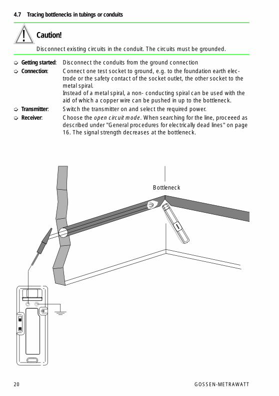
4.7 Tracing bottlenecks in tubings or conduits
Caution!!Disconnect existing circuits in the conduit. The circuits must be grounded.
Getting started: Disconnect the conduits from the ground connection Connection: Connect one test socket to ground, e.g. to the foundation earth elec-
trode or the safety contact of the socket outlet, the other socket to the metal spiral. Instead of a metal spiral, a non- conducting spiral can be used with the aid of which a copper wire can be pushed in up to the bottleneck.
Transmitter: Switch the transmitter on and select the required power. Receiver: Choose the open circuit mode. When searching for the line, proceeed as
described under "General procedures for electrically dead lines" on page 16. The signal strength decreases at the bottleneck.
Bottleneck

GOSSEN-METRAWATT 21
4.8 Locating faults on an electric floor heating system
Caution!!Make sure that the heating wire to be measured carries neither current nor voltage.
Getting started: Interrupt the connection of the shield matting and/or the coaxial shield braiding to ground, if available.
Connection: Connect one test socket to ground, e.g. to the safety contact of the socket outlet, the other socket to the heating wire.
Transmitter: Switch the transmitter on and select the required power. Take into ac-count here that the corresponding shielding causes a signal attenuation.
Receiver: When searching for the line, proceed as described under "General proce-dures for electrically dead lines" on page 16. The signal strength de-creases when the broken wire is reached.
Caution!!The connection of the shield matting and/or the coaxial shield braiding to ground must absolutely be restored after the measurement.

22 GOSSEN-METRAWATT
4.9 Locating underground lines (also in the case of a broken cable)
Caution!!Make sure that the line to be measured or the circuit to be measured is electrically dead.When using power supplies to increase the performance, only power supplies with safe electrical isolation must be used.
Connection: Connect one socket of the transmitter to the line running underground and the other one to the ground of the circuit to be tested.Neutral conductor and protective conductor must also be grounded to prevent capacitive couplings into the transmitting signal.
Transmitter: Switch the transmitter on and select the required power. Depending upon the location of the line, it may be required to increase the power of the transmitter via an external 24 V voltage source.
Receiver: Select the closed circuit mode here, regardless of the line being broken or not. Otherwise, search for the line as described under "General proce-dures for electrically dead lines" on page 16.
Even in the case of a broken cable, a sufficient signal current for location of the line normally flows through the soil here. If, however, no current flow takes place, it is also possible to measured in the open circuit mode.

GOSSEN-METRAWATT 23
5 Technical Data
5.1 General information
5.2 Receiver R300
5.3 Signal generator S330
5.4 Transmitter T320
Operating temperature −20 °C to +50 °C
Storage temperature −40 °C to +65 °C
Mode selection closed measuring circuit, live line max. 300 V
open measuring circuit, electrically dead line
Range selection Amplification: x 1, x 10 or x 100
with vernier amplification setting via thumb wheel
Battery 9 V flat cell battery 6LR61 or 6LF22 to IEC 68-2
Display 10 LED display with chroma filter
Material of case ABS 911 low inflammability
Weight 176 g incl. battery
Operating voltage 9 V ... 300 V AC/DC
Operating frequency 32 768 kHz
Signal Clock cycle 0.5 s; 2 pulses of 0.0625 s duration each
Mode selection Amplitude selectable Low (< 35 mA) High (70 mA)
Power consumption Peak value 4 mAs 6 mAs
Fuse Quick-acting, 250 mA/380 V, 6.3 x 32 mm
Material of case ABS 911 low inflammability
Weight 108 g
Operating frequency 32 768 kHz
Signal Clock cycle 0.5 s; 2 pulses of 0.0625 s duration each
Mode selection Selectable Low Medium High
Power consumption 9 V lead Peak value 3.0 As 1.8 As 1.0 As
Average 187 mA 106 mA 62.5 mA
24 V lead Peak value 18.0 As 6.0 As 3.0 As
Average 500 mA 312 mA 175 mA
Voltage 9 V lead Peak value 6.5 Vs 13.0 Vs 31.0 Vs
24 V lead Peak value 22.0 Vs 45.0 Vs 105.0 Vs
Fuse Quick-acting, 2 A/250 V, 6.3 x 32 mm
Battery 9 V flat cell battery 6LR61 or 6LF22 to IEC 68-2
Material of case ABS 911 low inflammability
Weight 182 g incl. battery

GOSSEN
M
ETRA
WATT
CAMILL
E BAUER
GOSSEN
M
ETRA
WATT
CAMILL
E BAUER
Printed in Germany ⋅ Subject to change without notice
GOSSEN-METRAWATT GMBHD-90327 Nürnberg
Company address:Thomas-Mann-Straße 16 – 20D-90471 NürnbergTelefon (09 11) 86 02 – 0Telefax (09 11) 86 02 – 6 69
6 Maintenance
6.1 Battery
If the standby LED of transmitter T320 or receiver does not light after turn-on, the battery is probably discharged. A discharged or deteriorating battery must not be left in the battery compartment.
Replacing the battery Disconnect the transmitter from the line. Press against the strap of the battery compartment and lift it upwards. Replace the bat-
tery. The battery compartment can only be closed again when the battery is installed with correct polarity.
6.2 Fuse link
The fuse holders of signal generator and transmitter are arranged at the front and are marked with the battery symbol.
Replacing the fuse link Disconnect the signal generator from the line. Withdraw the fuse holder and replace the fuse.
Caution!!Absolutely verify that only the specified fuse is installed! The use of a fuse of other cutout characteristics, other nominal current or other switching capacity endangers the user, and moreover, there is danger of damaging protective diodes, resistors or other components.
7 Repair and replacement parts service
In case of need, please contact:GOSSEN-METRAWATT GMBHServiceThomas-Mann-Straße 16 - 20D – 90471 NürnbergTelefon (09 11) 86 02 – 4 10 / 4 11Telefax (09 11) 86 02 – 2 53Telex 6 23 729 gome d
This address is for the Federal Republic of Germany only. Our representatives or establishments are at your disposal abroad.