cable testing and intallation
120
TESTING AND COMMISSIONING PROCEDURE FOR ELECTRICAL INSTALLATION IN GOVERNMENT BUILDINGS OF THE HONG KONG SPECIAL ADMINISTRATIVE REGION 2007 EDITION ARCHITECTURAL SERVICES DEPARTMENT THE GOVERNMENT OF THE HONG KONG SPECIAL ADMINISTRATIVE REGION
-
Upload
manishgoswami66 -
Category
Engineering
-
view
176 -
download
0
Transcript of cable testing and intallation
TESTING AND COMMISSIONING PROCEDURE
FOR
ELECTRICAL INSTALLATION
IN
GOVERNMENT BUILDINGS
OF
THE HONG KONG SPECIAL ADMINISTRATIVE REGION
2007 EDITION
ARCHITECTURAL SERVICES DEPARTMENT THE GOVERNMENT OF THE HONG KONG SPECIAL ADMINISTRATIVE REGION
PREFACE
This Testing and Commissioning (T & C) Procedure aims to lay down theminimum testing and commissioning requirements to be carried out on electricalinstallation in Government Buildings of the Hong Kong Special Administrative Region(HKSAR). Such requirements are applicable to both new installations upon completion andexisting ones after major alteration.
The present edition was developed based on its 2002 edition by the ElectricalSpecialist Support Group that was established under the Building Services BranchTechnical Information and Research & Development Committee. With the benefit ofinformation technology, electronic version of this new edition is to be viewed on and freefor download from the Architectural Services Department (ArchSD) Internet homepage. Aspart of the Government’s efforts to limit paper consumption, hard copies of this T & CProcedure will not be put up for sale.
The Architectural Services Department welcomes comments on its contents atanytime since the updating of this T & C Procedure is a continuous process to tie in withtechnological advances.
DISCLAIMER
This T & C Procedure is solely compiled for use on electrical installation carriedout for or on behalf of the ArchSD in Government buildings of the HKSAR.
There are no representations, either expressed or implied, as to the suitability of thisT & C Procedure for purposes other than that stated above. The material contained in this T& C Procedure may not be pertinent or fully cover the extent of the installation in non-government buildings. Users who choose to adopt this T & C Procedure for their works areresponsible for making their own assessments and judgement of all information containedhere. The Architectural Services Department does not accept any liability and responsibilityfor any special, indirect or consequential loss or damage whatsoever arising out of or inconnection with the use of this T & C Procedure or reliance placed on it.
Table of ContentsPage 1 of 5
EE_TCP2007 Edition
TABLE OF CONTENTSPage
1. Introduction 1
2. Objectives of the Testing and Commissioning (T&C) Works 1
3. Scope of the T&C Works 2
3.1 Preliminary Steps for Testing and Commissioning (T&C)Works
2
3.2 Testing and Inspection during Construction 2
3.3 Statutory Test and Inspection 3
3.4 Functional Performance Tests 3
3.5 Documentation and Deliverables 3
4. Testing and Commissioning (T&C) Procedures 4
4.1 Tests and Inspections during Construction 4
4.2 Statutory Inspection and Test for Low Voltage Installations 4
4.2.1 Inspection before Test 44.2.2 Sequence of Tests 54.2.3 Conductor Continuity 64.2.4 Insulation Resistance 74.2.5 Polarity 84.2.6 Earth Electrode Resistance 84.2.7 Earth Fault Loop Impedance 94.2.8 Functions of All Devices including Protective Devices 94.2.9 Additional Check for Installation in Hazardous
Environment10
4.3 Statutory Inspection and Test for High Voltage Installations 11
4.3.1 Inspection before Test 114.3.2 Safety 114.3.3 Testing Requirements 11
4.4 Functional Test of System /Equipment 11
4.4.1 Lightning Protection System 114.4.2 Circuitry Check 12
Table of ContentsPage 2 of 5
EE_TCP2007 Edition
TABLE OF CONTENTSPage
4.4.3 Charger and Battery Set 124.4.4 Lighting Installation 134.4.5 Digital Multifunction Power Meter 14
4.4.6 Digital Power Analyzer 144.4.7 Busbar Trunking System 154.4.8 Equipment and Appliances 154.4.9 Any Other Tests that are Considered Necessary to
Meet the Design Intent15
4.5 Assessment of Any Characteristics of Equipment Likely to haveHarmful Effects
16
4.6 Test and Inspection for Low Voltage Cubicle Switchboard 16
4.6.1 Visual Inspection 164.6.2 Site Test before Connection of Incoming Supply 174.6.3 Site Test after Connection of Incoming Supply 18
4.7 Power Energization 18
4.7.1 Notification of Completion 184.7.2 Preliminary Steps for Power Energization 194.7.3 Switch On Process 19
4.8 Calibrated Equipment 20
Annex
Annex I Testing and Commissioning Certificate on Electrical Installation
Annex II Testing and Commissioning Progress Chart for Electrical Installation
Annex III Testing and Commissioning Certificate on Low Voltage CubicleSwitchboard (LVSB) Installation
Annex IV Testing and Commissioning Progress Chart for Low Voltage CubicleSwitchboard (LVSB) Installation
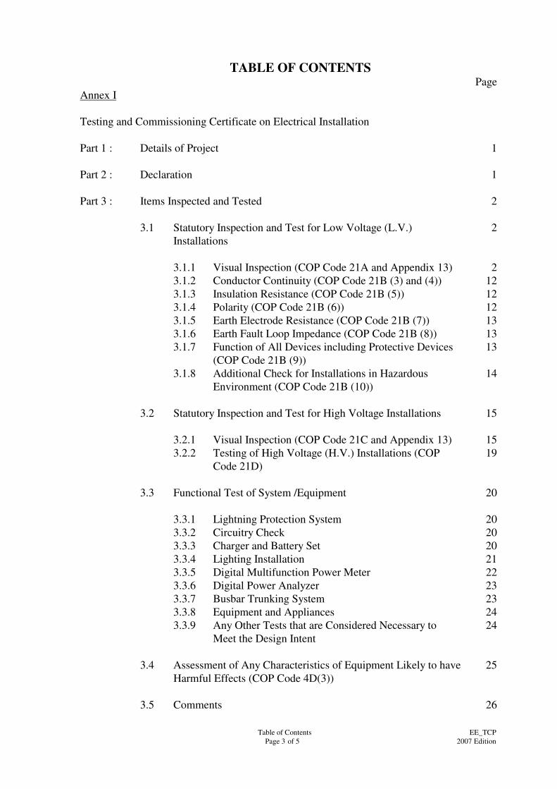
Table of ContentsPage 3 of 5
EE_TCP2007 Edition
TABLE OF CONTENTSPage
Annex I
Testing and Commissioning Certificate on Electrical Installation
Part 1 : Details of Project 1
Part 2 : Declaration 1
Part 3 : Items Inspected and Tested 2
3.1 Statutory Inspection and Test for Low Voltage (L.V.)Installations
2
3.1.1 Visual Inspection (COP Code 21A and Appendix 13) 23.1.2 Conductor Continuity (COP Code 21B (3) and (4)) 123.1.3 Insulation Resistance (COP Code 21B (5)) 123.1.4 Polarity (COP Code 21B (6)) 123.1.5 Earth Electrode Resistance (COP Code 21B (7)) 133.1.6 Earth Fault Loop Impedance (COP Code 21B (8)) 133.1.7 Function of All Devices including Protective Devices
(COP Code 21B (9))13
3.1.8 Additional Check for Installations in HazardousEnvironment (COP Code 21B (10))
14
3.2 Statutory Inspection and Test for High Voltage Installations 15
3.2.1 Visual Inspection (COP Code 21C and Appendix 13) 153.2.2 Testing of High Voltage (H.V.) Installations (COP
Code 21D)19
3.3 Functional Test of System /Equipment 20
3.3.1 Lightning Protection System 203.3.2 Circuitry Check 203.3.3 Charger and Battery Set 203.3.4 Lighting Installation 213.3.5 Digital Multifunction Power Meter 223.3.6 Digital Power Analyzer 233.3.7 Busbar Trunking System 233.3.8 Equipment and Appliances 243.3.9 Any Other Tests that are Considered Necessary to
Meet the Design Intent24
3.4 Assessment of Any Characteristics of Equipment Likely to haveHarmful Effects (COP Code 4D(3))
25
3.5 Comments 26
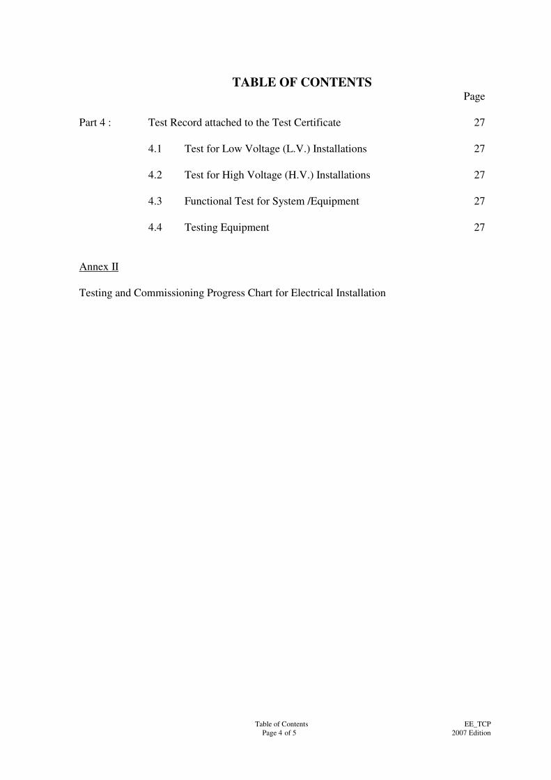
Table of ContentsPage 4 of 5
EE_TCP2007 Edition
TABLE OF CONTENTSPage
Part 4 : Test Record attached to the Test Certificate 27
4.1 Test for Low Voltage (L.V.) Installations 27
4.2 Test for High Voltage (H.V.) Installations 27
4.3 Functional Test for System /Equipment 27
4.4 Testing Equipment 27
Annex II
Testing and Commissioning Progress Chart for Electrical Installation
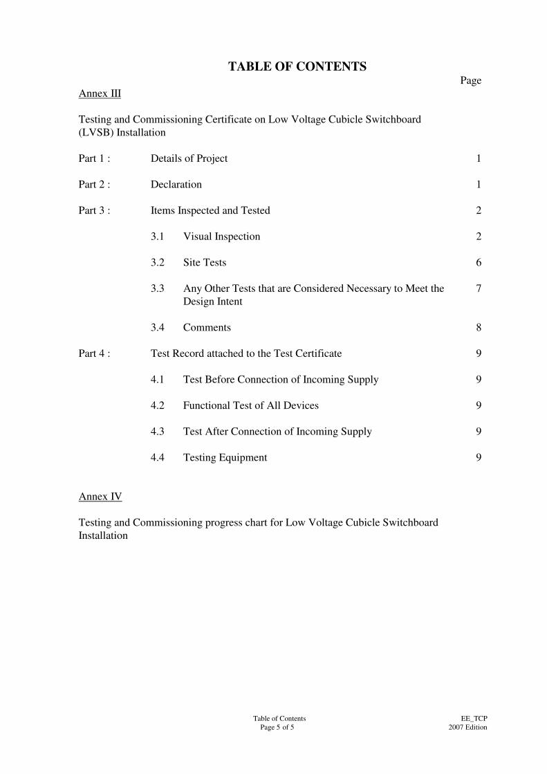
Table of ContentsPage 5 of 5
EE_TCP2007 Edition
TABLE OF CONTENTSPage
Annex III
Testing and Commissioning Certificate on Low Voltage Cubicle Switchboard(LVSB) Installation
Part 1 : Details of Project 1
Part 2 : Declaration 1
Part 3 : Items Inspected and Tested 2
3.1 Visual Inspection 2
3.2 Site Tests 6
3.3 Any Other Tests that are Considered Necessary to Meet theDesign Intent
7
3.4 Comments 8
Part 4 : Test Record attached to the Test Certificate 9
4.1 Test Before Connection of Incoming Supply 9
4.2 Functional Test of All Devices 9
4.3 Test After Connection of Incoming Supply 9
4.4 Testing Equipment 9
Annex IV
Testing and Commissioning progress chart for Low Voltage Cubicle SwitchboardInstallation
Page 1 of 21EE_TCP
2007 Edition
Testing and Commissioning Procedure forElectrical Installation
1. Introduction
The procedures stated in this document cover the activities in preliminary tests andinspections, functional performance tests and the commissioning of newly completedinstallations and existing ones after major alteration. They are so compiled to facilitatethe work of Project Building Services Engineer (PBSE) and Project Building ServicesInspector (PBSI) in the following aspects with respect to testing and commissioning(T&C):
(i) To vet and approve the T&C procedures proposed and submitted by theContractor;
(ii) To witness those T&C procedures as specified; and
(iii) To accept the T&C certificates and other supporting data.
The Contractor shall carry out the T & C works as detailed in this document.Supplementary T&C plans may be proposed by the Contractor as appropriate andagreed by PBSE, e.g. for special equipment supplied and/or installed by the Contractor.
The administrative requirements for T & C works are in general as specified in thelatest General Specification for Electrical Installation (the General Specification) issuedby the Building Services Branch of the Architectural Services Department. If there isany discrepancy between this procedure and the General Specification, the GeneralSpecification shall take precedence.
“Major Alteration” of an existing electrical installation means alteration involving workon any distribution board or electrical equipment having an electrical current ratingexceeding 100A single phase or 60A three phases in an existing electrical installation.
This procedure is also intended to lay down the minimum testing and commissioningrequirements to be carried out by the Contractor on a new Low Voltage CubicleSwitchboard Installation upon completion or on an existing Low Voltage CubicleSwitchboard Installation after a major alteration involving modification of the mainbusbar such as upgrading, reposition and extension.
2. Objectives of the Testing and Commissioning (T&C) Works
The objectives of the T & C works are:
(i) To verify proper functioning of the equipment/system after installation; and
(ii) To verify that the performance of the installed equipment/systems meet withthe specified design intent through a series of tests and adjustments.
(iii) To capture and record performance data of the whole installation as thebaseline for future operation and maintenance.
Page 2 of 21EE_TCP
2007 Edition
For the avoidance of doubt, depending on the specific demands of individualinstallation, the PBSE may require additional or substitute T & C works in regard to anyelements in the installation other than those indicated in this Procedure.
3. Scope of the Testing and Commissioning (T&C) Works
3.1 Preliminary Steps for Testing and Commissioning
Before carrying out T&C, the Contractor shall take the following steps:
(a) Submit draft T&C procedures to the PBSE for approval. The draftT&C procedures shall include essential procedures mentioned in thisprocedure plus additional T&C procedures required for specificinstallations as well as manufacturer’s recommendation;
(b) Obtain design drawings and specifications and to be thoroughlyacquainted with the design intent;
(c) Obtain copies of approved shop drawings and equipment schedules;
(d) Review approved shop drawings and equipment schedules;
(e) Check manufacturer’s operating instructions and statutoryrequirements;
(f) Physically inspect the installation and equipment to determinevariations from designs and/or specifications.
(g) Check individual components, e.g. key switches, control equipment,circuit breaker status, etc. for proper position and settings forcompleteness of installation.
(h) Check inclusion of manufacturer’s typical equipment testing data orfactors before T&C of particular equipment.
3.2 Testing and Inspection during Construction
The purpose of these tests is to ensure that all components and systems are in asatisfactory and safe condition before start up. Preliminary adjustment andsetting of equipment at this stage shall also be carried out at the same time topave way for the coming functional performance tests.
Before carrying out any test, the Contractor shall ensure that the installationcomplies with all relevant statutory requirements and regulations. The T&Cworks shall comply with all site safety regulatory requirements currently inforce, including but not limited to:
(i) Electricity Ordinance, Chapter 406, and other subsidiary legislationherein;
Page 3 of 21EE_TCP
2007 Edition
(ii) The Code of Practice for the Electricity (Wiring) Regulations (COP)
(iii) IEC 60364 “Electrical Installations of Building”
(iv) Electricity supply rules of the relevant power supply companies
3.3 Statutory Test and Inspection
The statutory test and inspection herein stated in this T&C procedure shall referto the Regulations Nos. 19, 20, 21 and 22 of the Electricity (Wiring)Regulations under the Electricity Ordinance Chapter 406E.
3.4 Functional Performance Tests
The purpose of functional performance tests is to demonstrate that theequipment/installation can meet the functional and performance requirementsas specified in the General/Particular Specifications. Functional performancetest should proceed from the testing of individual components to the testing ofdifferent systems in the installation.
The Contractor may have to make temporary modifications as the testproceeds. The specific tests required and the order of tests will vary dependingon the type and size of systems, number of systems, sequence of construction,interface with other installations, relationship with the building elements andother specific requirements as indicated in the General/ParticularSpecifications. The testing of systems may have to be carried out in stagesdepending on the progress of work or as proposed by the Contractor.
Part of the tests may be required to be carried out in suppliers’ premises inaccordance with the provisions in the General/Particular Specification.
Any performance deficiencies revealed during the functional performance testsmust be evaluated to determine the cause and whether they are part of thecontractual obligations. After completion of the necessary corrective measures,the Contractor shall repeat the tests.
If any test cannot be completed because of circumstances that are beyond thecontrol of the Contractor, it shall be properly documented and reported to thePBSE, who shall then liaise with the relevant parties to resolve the situation.The Contractor shall resume his testing work immediately upon the attainmentof a suitable testing environment.
3.5 Documentation and Deliverables
The Contractor shall submit his proposed T&C procedures together with theTesting and Commissioning Progress Chart shown in Annex I to Annex IV,where applicable, to PBSE for approval.
All inspection and T&C results shall be recorded by the Contractor in theappropriate test record forms, the reference of which is shown against eachindividual test. Sample of these forms can be found in Annex I and Annex III.
Page 4 of 21EE_TCP
2007 Edition
Data recorded in other formats may also acceptable subject to agreementbetween the PBSE and the Contractor. Upon completion of all the requiredT&C works, the Contractor’s project engineer shall complete and sign thetesting and commissioning certificate as shown in Part 1 and 2 of Annex Iand/or Annex III to the effect that the agreed T&C works have been dulycarried out.
Functional test reports covering all measured data, data sheets, and acomprehensive summary describing the operation of the system at the time ofthe functional tests shall be prepared and submitted to the PBSE. Deviations inperformance from the General/Particular Specifications or the design intentshould be recorded, with a description and analysis included.
Where required in the General/Particular Specification, the Contractor shallconduct a final evaluation of the performance of the Electrical Installation, theresults of which shall be included in the commissioning report.
The Contractor shall sign work completion certificate(s) and issue to the PBSEafter completion of the electrical installation or any work subsequent to repair,alteration or addition to an existing installation. This should be done before theinstallation is energized.
4. Testing and Commissioning (T&C) Procedures
4.1 Tests and Inspections during Construction
For those tests to be carried out on different systems of the installation duringconstruction to ensure their suitability for operating at the design conditions,certificates of such tests shall be issued together with certificates of any worktests.
The Contractor shall submit the details of the tests and inspection duringconstruction to PBSE for approval on commencement of the installation work.
The tests and inspection shall include, but not limited to, the followings:
(a) Visual inspection;
(b) Earth electrode resistance; and
(c) Continuity of protective conductor.
Details of these tests shall be in accordance with relevant sections of thisprocedure.
4.2 Statutory Inspection and Test for Low Voltage Installations
4.2.1 Inspection before Test
A visual inspection shall be made to verify that the electrical
Page 5 of 21EE_TCP
2007 Edition
installation /equipment as installed is correctly selected and erected inaccordance with the COP Code 21A and COP Appendix 13, and thatthere is no apparent damage. The visual inspection shall include acheck on the following items, where appropriate:
(a) Adequacy of working space, access, and maintenancefacilities;
(b) Connections of conductors;
(c) Identification of conductors;
(d) Adequacy of the sizes of conductor in relation to currentcarrying capacity and voltage drop;
(e) Correct connections of all equipment with special attention tosocket outlets, lampholders, isolators, switches, residualcurrent devices, miniature circuit breakers, and protectiveconductors,
(f) Presence of fire barriers and protection against thermaleffects;
(g) Methods of protection against direct contact with live parts(including measurement of distances where appropriate), i.e.protection by insulation of live parts, or protection by barriersor enclosures;
(h) Presence of appropriate devices for isolation and switching;
(i) Choice and setting of protective and indicative devices;
(j) Labelling of circuits, fuses, protective devices, switches,isolators and terminals;
(k) Selection of equipment and protective measures appropriate toadverse environmental conditions;
(l) Presence of danger and warning notices;
(m) Presence of diagrams, instructions and other similarinformation;
(n) Connection of single pole devices for protection or switchingin phase conductors only;
(o) Method of protection against indirect contact;
(p) Prevention of mutual detrimental influence;
(q) Presence of undervoltage protective devices;
Page 6 of 21EE_TCP
2007 Edition
(r) Erection method; and
(s) Any other appropriate inspection as listed in COP Appendix13.
4.2.2 Sequence of Tests
The following items, where relevant, are to be tested preferably in thesequence indicated below:
(a) Continuity of protective conductors, including main andsupplementary equipotential bonding,
(b) Continuity of ring final circuit conductors,
(c) Insulation resistance,
(d) Polarity,
(e) Earth electrode resistance,
(f) Earth fault loop impendance,
(g) Functions of all protective devices,
(h) Functions of all items of equipment.
In the event of any test indicating failure to comply, that test and thosepreceding, the results of which may have been influenced by the faultindicated, shall be repeated after the fault has been rectified.
4.2.3 Conductor Continuity
(a) Continuity of Protective Conductors
The test shall be in accordance with COP Code 21B (3).
Every protective conductor, including all conductors and anyextraneous conductive parts used for equipotential bondingshould be tested for continuity. The test should be made byconnecting together the neutral and protective conductors atthe mains position and checking between earth and neutral atevery outlet by a continuity tester, which should show areading near zero.
(b) Continuity of Ring Final Circuit
The test shall be in accordance with COP Code 21B (4).
The ring circuit should be tested from the distribution board.
Page 7 of 21EE_TCP
2007 Edition
The ends of the two cables forming the phase conductorshould be separated, and a continuity test should show areading near zero between the two; the same tests to be madebetween the two cables that form the neutral conductor, andbetween the two cables that form the protective conductor.
The testing method in above paragraph is only applicablewhen the ring circuit has been inspected throughout, prior tothe test, to ascertain that no interconnection (multi-loops)exists on the ring circuit. Otherwise, the testing methodsstipulated in Part 3 of the Guidance Note 3 to BS7671, shouldbe adopted instead.
4.2.4 Insulation Resistance
The test shall be in accordance with COP Code 21B (5).
A suitable direct current (d.c.) insulation tester should be used tomeasure insulation resistance. Care should be taken to ensure that theinsulation of the equipment under test could withstand the test voltagewithout damage.
To carry out this test, it is acceptable to divide large installation intosections with groups of outlets, each group containing not less than 50outlets. The term outlet in this case includes every point andevery switch. A socket outlet or appliance or luminaire incorporating aswitch is regarded as one outlet.
When measured with all fuse links in place, all switches and circuitbreakers (including, if practicable, the main switch) closed and allpoles or phases of the wiring electrically connected together, theinsulation resistance to earth should not be less than the appropriatevalues given in Table 21 (1) of COP. For best practice, the insulationresistance shall not be lower than 1.0 mega ohm for low voltageinstallation under a test voltage of d.c. 500V.
When measured between all conductors connected to any one phase orpole of the supply and, in turn, all conductors connected to each otherphase or pole, the insulation resistance should not be less than theappropriate values in Table 21(1) of COP. For best practice, theinsulation resistance shall not be lower than 1.0 mega ohm for lowvoltage installation under a test voltage of d.c. 500V.
For the sake of enhanced safety, when the value of insulationresistance measured is near the minimum values as required in thisT&C procedure, or at a relatively low valves where consideredabnormal to trade’s practice, the concerned circuit /installation shall bere-checked to improve and re-test shall be conducted afterward.
In carrying out the test:
Page 8 of 21EE_TCP
2007 Edition
(a) wherever practicable, all lamps should be removed and allcurrent using equipment should be disconnected and all localswitches controlling lamps or other equipment should beclosed;
(b) where the removal of lamps and/or the disconnection ofcurrent using equipment is impracticable, the local switchescontrolling such lamps and/or equipment should be open;
(c) electronic devices connected in the installation should beisolated or short circuited where appropriate so that they arenot damaged by the test voltage.
(d) where the circuits contain voltage sensitive devices, the testshould measure the insulation resistance to earth with all liveconductors (including the neutral) connected together.
The sequence of test shall be as follows:
(1) Main switch/switchboard and outgoing circuits with sub-mainswitches being isolated;
(2) Sub-main switches/switchboards and outgoing circuits withfinal circuits boards being isolated; and
(3) Final circuit boards and final circuits.
Where equipment is disconnected for the test and the equipment hasexposed conductive parts require to be connected to protectiveconductors, the insulation resistance between the exposed conductiveparts and all live parts of the equipment should be measured separatelyand should have a minimum insulation resistance not less than 0.5MegaOhm.
For Site Built Assemblies, the insulation applied to the live parts ofthe assemblies for protection against direct contact shall be tested withan applied voltage equivalent to that specified in the appropriateRegulation and/ or COP for similar factory-built equipment. Thesupplementary insulation of Site Built Assemblies for protectionagainst indirect contact shall be tested for degree of protection not lessthan IP 2X, and the insulation enclosure shall be tested with an appliedvoltage equivalent to that specified in the appropriate Regulation and/or COP for similar factory-built equipment.
4.2.5 Polarity
The test shall be in accordance with COP Code 21B (6).
A test of polarity should be carried out to verify that:
(a) every fuse and single-pole control and protective device is
Page 9 of 21EE_TCP
2007 Edition
connected in the phase conductor only,
(b) centre-contact bayonet and Edison-type screw lampholders toIEC 60238 in circuits having an earthed neutral conductor,have their outer or screwed contacts connected to that neutralconductor, and
(c) wiring has been correctly connected to socket outlets andsimilar accessories.
4.2.6 Earth Electrode Resistance
The test shall be in accordance with COP Code 21B (7).
A proper earth electrode resistance tester should be used to measureearth electrode resistance. An alternating current at 50 Hz of a steadyvalue is passed between the earth electrode T and an auxiliary earthelectrode T1 placed at a separation distance recommended by themanufacturer of the tester but in any case should not be less than 20metres away. A second auxiliary earth electrode T2, which may be ametal spike driven into the ground, is then inserted half-way betweenT and T1, and the voltage drop between T and T2, divided by thecurrent flowing between T and T1, gives a measured earth electroderesistance of earth electrode T.
For an electrical installation having four or more earth electrodeswhich are installed more or less in line, following a general directionnot exceeding 15 deviation and with separation between adjacentelectrodes not less than the recommended distance by themanufacturer of the tester but in any case not less than 20 metres,these electrodes can be used in turn as the auxiliary electrodes for thepurpose of measuring the earth electrode resistances.
The following alternative method for measuring the earth electroderesistance may be used if the electricity supply is connected. A loopimpedance tester should be connected between the phase conductor atthe origin of the installation and the earth electrode with the test linkopen, and a test performed. This impedance reading could be treatedas the electrode resistance.
4.2.7 Earth Fault Loop Resistance
The test shall be in accordance with COP Code 21B (8).
The earth fault loop impedance should be measured by a phase-earthloop tester with a scale calibrated in ohms.
The earth fault loop impedance should not exceed the requirements ofCOP Code 11.
Before the test begins, it is essential to establish, by inspection, that
Page 10 of 21EE_TCP
2007 Edition
the earthing conductor and all relevant earth connections are in place,and that the bonding connection to electricity supplier’s earthingfacilities is disconnected. Measures should be taken, during theimpedance tests especially when the earth leakage protective devicesare effectively removed for the duration of the tests, to ensure that theinstallation is not being used other than by person(s) carrying out thetests.
4.2.8 Functions of All Devices including Protective Devices
The test shall be in accordance with COP Code 21B (9).
Functional Test of Residual Current Device (RCD):
(a) Function of residual current devices should be checked by aresidual current device tester simulating an earth fault inorder to verify its effective operation. The in-built test buttonshould also be tested for proper functioning. One of thetesting methods is specified in subparagraph (b) and (c)below. Other testing methods complying with relevantnational/international standards are also acceptable.
(b) The test should be made on the load side of the RCD betweenthe phase conductor of the protected circuit and the associatedcircuit protective conductor. The load should be disconnectedduring the test.
(c) For general purpose RCDs to IEC 61008 or RCBOs toIEC61009, with a leakage current flowing equivalent to 50%of the rated tripping current of the RCD, the device shouldnot open. When a leakage current is flowing equivalent to100% of the rated tripping current of the RCD, the deviceshould open in less than 300 ms unless it is of Type S (orselective) which incorporates an intentional time delay, whenit should trip within the time range from 130 ms to 500 ms.
Function of other protective devices, such as miniature circuitbreakers, moulded case circuit breakers, air circuit breakers, fusedswitches, switch-fuses and protective relays etc. should be checked byhand operation as appropriate.
Function of all items of equipment such as isolators, switches andindicative devices should be checked by hand operation.
4.2.9 Additional Check for Installation in Hazardous Environment
The following additional check, where appropriate, shall be carried outfor installations in hazardous environment in accordance with COPCode 21B (10):
(a) Where appropriate, the area involved should be checked to
Page 11 of 21EE_TCP
2007 Edition
ensure ‘gas free’ condition before insulation and earth faultloop impedance test are carried out.
(b) All equipment should be suitably protected according to thetypes of protection under COP Code 15. The integrity of thetype of protection provided for the equipment should not bejeopardised by the method of installation. No alteration thatmay invalidate the conditions of protection can be used.
(c) Equipment should be kept clean and free from accumulationof dust, foreign particles and deleterious substances.Equipment is kept free from condensation.
(d) All lamps, fuses and replaceable parts should be checked sothat correct rating and types are being used.
(e) The surface temperature of all equipment should beappropriate to the type of protection being provided.
4.3 Statutory Inspection and Test for High Voltage Installations
4.3.1 Inspection before Test
The inspection shall be in accordance with COP Code 21C.
Inspection of H.V. installations should follow those for L.V.installations listed in section 3.5 of this procedure with additionalchecks on the following items where relevant:
(a) provision of suitable locking facilities for every entry to anH.V. switchroom/substation;
(b) continuity of protective conductors especially the bonding ofall exposed conductive parts; and
(c) provision of padlock facilities for shutters, key boxes etc.
4.3.2 Safety
Precautionary measures should be taken and the methods of testsshould be such that no danger to persons or property can occur even ifthe circuit being tested is defective.
Before carrying out the T&C for high voltage installations, theContractor shall submit risk assessment, safety plan andimplementation procedure to PBSE for approval.
4.3.3 Testing Requirements
Testing for High Voltage installations should be referred to relevant
Page 12 of 21EE_TCP
2007 Edition
recognized standards, manufacturers’ recommendation, operations andmaintenance instructions.
The Contractor shall responsible to submit a full T&C plan withinspection and test details to PBSE for approval.
4.4 Functional Test of System /Equipment
4.4.1 Lightning Protection System
The whole lightning protection system shall be tested for continuitybetween air terminations and earthing terminations and the resistanceshall be recorded.
The earth termination resistance shall be tested and recorded. Eachearth termination shall have a resistance to earth not exceeding theproduct given by 10 times the number of earth terminations to beprovided. The whole of the lightning protection system shall have acombined resistance to earth not exceeding 10 .
Where the steel work of the structure is used as down conductor, thecontinuity of the steel work shall be tested and recorded.
Locations of all earth electrodes and down tape routing shall bechecked to be clear of any dangerous goods store, diesel tanks andinflammable stores, etc.
All connections at terminations, tee off points and earth electrodesshall be checked for tightness.
4.4.2 Circuitry Check
All circuits shall be verified through switching operation to ensure thatthe circuits are installed in accordance with the designated circuit. Thetests shall include but not be limited to the following:
(a) on/off switching of the lighting circuit to ensure that thelighting circuit is installed corresponding to the lightingswitch, protective device and labelling;
(b) switching of the general power circuit to ensure that thecircuit corresponds to the protective device such as RCD,RCBO and MCB, and that the protective device performs inaccordance with the designated duty;
(c) switching of the main switch / isolator to ensure thecorresponding circuit is properly controlled by the mainswitch / isolator;
(d) switching of all sub-main and main distribution circuits, e.g.busducts, cable feeders, underground cables, etc. to ensure the
Page 13 of 21EE_TCP
2007 Edition
correct isolation of the connected circuit;
(e) switching of all changeover switches to ensure the changingover sequence corresponds to the design criteria;
(f) ensuring all the protective devices perform properly againstthe designated circuit.
4.4.3 Charger and Battery Set
The following inspections and tests shall be carried out aftercompletion of the installation of the respective system and theconnection of the permanent supply cable:
(a) inspection of the charger for correct connection to the mainssupply through a suitable rated fuse;
(b) inspection of the batteries proper connections;
(c) inspection of instruments, indicating lamps, fuses, relays andlabels on battery charger;
(d) for initial set-up, the batteries shall be charged at the manualhighest rate until the charging current remains constant. Thestarting and finishing time are recorded. The capacity ofcharger is checked for capability of recharging the batteriesfrom fully discharged to fully charged within the specifiedduration;
(e) the charger output on load with batteries disconnected shallbe measured. This should be between 110% and 115% of thenormal batteries voltage and within the operating voltagelimits of all connected devices;
(f) the charger current on load with battery disconnected shall bemeasured. This should be less than the maximumrecommended continuous charge current for the batteries;
(g) on interruption of mains input to the charger, the properoperation of connected devices on standby batteries shall bechecked. In the case of switch tripping in Switchboard, mainsinput shall be interrupted to check whether the capacity of thebatteries is adequate to trip the associated air circuit breakerconsecutively at least 20 times or up to twenty air circuitbreakers simultaneously, whichever the greater;
(h) the correct function of charger fail/mains fail/batterydisconnected/boost charge/trickle charge indications asspecified shall be checked.
4.4.4 Lighting Installation
Page 14 of 21EE_TCP
2007 Edition
Lighting installation shall be tested in terms of its light quality andcontrol as following:
(a) Before carrying out the lighting measurement and test, allluminaries shall be checked against the specified colourtemperature, beaming angle of spot lamp and aiming anglefor exterior floodlights.
(b) The aiming angle of external lighting or planter lighting shallbe commissioned so as not to create glare or any obstructivelight to external environment.
(c) Before commissioning and /or setting of lighting controldevices which including but not limited to timer switch,occupancy sensor, photocell and infra-red sensor, theContractor shall submit commissioning /setting proposal toPBSE for approval.
(d) Illumination level of lighting installation for individual areas/rooms shall be measured to verify the light output. TheContractor shall submit the proposed locations and heightlevels for carrying out the measurement of illuminance levelto PBSE for approval before commencement ofmeasurement. Presentation of the measurement result shall bein the form of marked up layout plan for the particular area.
(e) Base on the measured illuminance results for individual areas/rooms, the lighting uniformity of the respective areas /roomsshall be evaluated in terms of minimum to averageilluminance ratio and/ or any other uniformity ratio asrequired by the PBSE.
(d) All grouping of luminaries shall be tested by hand operationof the corresponding switches or timers.
(e) For lighting installation with interface connection to buildingmanagement system (BMS), or central control andmonitoring system (CCMS) or similar central computercontrol system, the Contractor shall co-ordinate with othercontractors responsible for such computer control system, ifrequired, to demonstrate proper control function of thelighting installation.
4.4.5 Digital Multifunction Power Meter
The digital multifunction power meter shall be tested to verify themeasurement, recording and interfacing functions as required in theGeneral Specification.
Prior to the test for every digital multifunction power meter, the
Page 15 of 21EE_TCP
2007 Edition
Contractor shall provide manufacturer’s calibration certificate for eachmeter for checking on the accuracy.
The Contractor shall provide testing kit to verify the reading accuracyof the digital multifunction power meter.
For installation of digital multifunction power meter with connectionto building management system (BMS), or central control andmonitoring system (CCMS) or similar central computer monitoringsystem, the Contractor shall co-ordinate with other contractorresponsible for such computer monitoring system, if required, todemonstrate proper functioning and interfacing of the meter.
For installation of digital multifunction power meter without externalconnection to building management system or CCMS, the interfacefunctions including digital and analogue output shall be tested bymeans of plugging in communication module provided by theContractor.
The replacement mechanism of the meter shall be tested. The test shalldemonstrate that the replacement of the meter does not require theswitching off of the respective switchgear. Current transformersshorting block to prevent open circuiting the current transformers shallalso be tested.
4.4.6 Digital Power Analyzer
The testing requirement for digital power analyser shall be inaccordance to section 3.9.5.
In addition to test requirement as stipulated in section 3.9.5, the eventalarm function and waveform capture function of the digital poweranalyser shall also be tested. The Contractor shall propose simulatedtest method for PBSE’s approval.
4.4.7 Busbar Trunking System
In general, busbar trunking system shall be certified by testinglaboratories or organizations as stated in the COP. It shall be typetested in accordance with Clause 8.1.1 of IEC 60439-2. Theverification of short-circuit strength shall be carried out by anIndependent Short Circuit Testing Organization.
Short-circuit test on the phase and neutral busbars shall be carried outin accordance with Clause 8.2.3 of IEC 60439-1 to the value of short-circuit current specified in the General Specification.
The busbar insulation shall be tested in accordance with Clause 8.2.2of IEC 60439-1. All test certificates shall be presented duringinspection and testing.
Page 16 of 21EE_TCP
2007 Edition
The busbar trunking system shall also be tested to verify its continuity,insulation resistance, polarity, earth fault loop impedance and otherparameters as appropriate after installation.
For installation of busbar trunking with long run, phase transpositionof busbar in accordance with manufacturer’s recommendation shall bechecked.
Plug-in tap-off unit of busbar trunking system shall be tested to verifyproper and safe operation. Mechanical interlock, quick fastening andquick releasing mechanism of the tap-off unit shall be tested. Positiveearth connection of tap-off unit shall be checked.
After power energization of the busbar trunking system, infraredscanning at connecting joints shall be carried out to check forabnormal rise in temperature at joints. The Contractor shall submitproposal of the test methodology and propose testing points for PBSEapproval prior to the test.
4.4.8 Equipment and Appliances
Testing on electrical equipment and appliances supplied within theelectrical installation, e.g. meters, fans, etc. shall be carried out inaccordance with the relevant sections of other Building ServicesBranch Testing and Commissioning Procedures for other buildingservices installations and manufacturer’s recommended testingprocedures.
4.4.9 Any Other Tests that are Considered Necessary to Meet the DesignIntent
For any other system /equipment that are not covered by this T&CProcedure, the contractor shall submit full details of testingrequirements as recommended by the relevant manufacturer to PBSEfor approval.
4.5 Assessment of Any Characteristics of Equipment Likely to have HarmfulEffects
Before carrying out the T&C, the Contractor shall conduct assessment for anycharacteristics of equipment likely to have harmful effects upon other electricalequipment or other services, or impair the supply. Those characteristicsinclude the following:
(a) Overvoltages;
(b) Undervoltages;
(c) Fluctuating loads;
(d) Unbalanced loads;
Page 17 of 21EE_TCP
2007 Edition
(e) Power factor;
(f) Starting currents;
(g) Harmonic currents;
(h) Direct current (d.c.) feedback;
(i) High frequency oscillations; and
(j) Necessity for additional connection to earth.
The Contractor shall, after conduct the assessment, submit an assessment reportto PBSE for consideration.
4.6 Test and Inspection for Low Voltage Cubicle Switchboard (LVSB)
The following sections stipulated the additional inspection and testingrequirements for LVSB installation. For comprehensive testing andcommissioning, the Contractor shall also refer to relevant sections of this T&CProcedure and carry out inspection /test accordingly.
4.6.1 Visual Inspection
Visual inspection shall be carried out for the proper installation of theLVSB Installation in accordance with the Specification. The followingcomponents shall be included:
(a) construction of type tested assembly;
(b) main busbars and droppers/risers;
(c) air circuit breakers/fuse switches;
(d) power factor correction capacitor bank;
(e) harmonic filter;
(f) automatic Changeover Switch;
(g) instrumentation and protection devices;
(h) incoming/outgoing busbars and cables;
(i) portable earthing equipment;
(j) operating handles/keys;
(k) hydraulic truck;
Page 18 of 21EE_TCP
2007 Edition
(l) rubber insulation mat.
4.6.2 Site Test before Connection of Incoming Supply
The following tests shall be carried out on site after completion ofinstallation of the LVSB and before the connection of the incomingsupply cable:
(a) Dielectric Test
Dielectric test shall be carried out to verify the dielectricproperties of the LVSB. The test requirements shall be inaccordance to IEC 60439-1.
(b) Insulation Test
This shall be carried out by means of a 1000V insulationtester or similar instrument.
(c) Secondary Injection Test
This shall be carried out using a.c. and shall check(approximately) that protection relays or devices function inaccordance with their performance curves by a test at thelowest setting and two further tests of current and timing.
(d) Primary Injection Test
This shall be carried out to prove the correct operation ofprotective devices or system when set at the agreed setting.
(e) Polarity Check for Current Transformer (C.T.)
This shall be carried out to ensure that all C.T. are correctlyconnected.
(f) Functional Test of All Devices
This shall be carried out to ensure that all devices can operateproperly as intended.
The equipment to be tested shall include, but not limited to,all circuit breakers, isolating switches, changeover switches,contactors, interlocking facilities, protective relays, earthleakage tripping devices, metering facilities and instruments.
(g) Contact Resistance Test
This shall be carried out by means of "Ductor" tester orsimilar instrument to ensure that contacts and joints forswitchgears, cables, busbars as well as the contacts and joints
Page 19 of 21EE_TCP
2007 Edition
for outgoing cables and busbars are maintained in goodcondition.
(h) Temperature Rise Limits Test
This shall be carried out as defined in IEC 60439-1.
With the prior approval by the PBSE, the primary injection test andtemperature rise limits test can be carried out in factory due to siteconstraints.
4.6.3 Site Test After Connection of Incoming Supply
The following tests shall be carried out after the incoming supplycables are connected and the “Switchboard” successfullycommissioned on no load:
(a) phase-to-phase voltage test;
(b) phase-to-neutral voltage test;
(c) phase-to-earth voltage test;
(d) neutral-to-earth voltage test;
(e) phase sequence test on each and every outgoing circuit.
4.7 Power Energization
4.7.1 Notification of Completion
After the proper testing and commissioning of the electricalinstallation, the Contractor shall notify the appropriate Authority,through the PBSE, on the completion of the installation and itsreadiness for inspection and testing.
4.7.2 Preliminary Steps for Power Energization
The followings shall be checked before power energization:
(a) busbar chambers, main and sub-main switch connections i.e.bolts and nuts tightness;
(b) earthing connections at compartments, all switches and earthelectrodes;
(c) clearance of live parts from direct contact with or anylikelihood of contact with tools, spurious bare conductorsremaining in switches, air circuit breakers (ACB) and switchcubicles;
Page 20 of 21EE_TCP
2007 Edition
(d) polarity, phase sequence of all switches and relevant fuseratings;
(e) stand-by battery supply and the operation of shunt tripmechanism;
(f) settings of overcurrent, earth fault relays and currenttransformer (C.T.) polarity;
(g) vacuum cleaning of switches and ACBs;
(h) provision of danger and warning signs.
(i) Certified Work Completion Certificate in accordance to therequirement of COP Code 19.
4.7.3 Switch On Process
Whenever there is any break of time e.g. the next day, in carrying outthe switch on process, re-test of insulation resistance is required. Thefollowing procedures shall be followed in the switch on process:
(a) switch on the main switch/ACB with all other sub-mainswitches off;
(b) if normal, switch on other sub-main switches one by one withall other outgoing switches off;
(c) if normal, then switch on all other out-going switches one byone;
(d) observe the disc of the overcurrent (o/c) and earth faultprotection relays for any movement for IDMT relays or fordigital protection relays check whether there are any faultindications;
(e) keep vigilance for about 30 minutes to see if any smell orabnormal noise being generated.
4.8 Calibrated Equipment
4.8.1 The Contractor shall supply the calibrated equipment relevant forT&C of the electrical installation as stipulated in the particularspecification of the contract or the General Specification whicheverappropriate. The equipment shall be calibrated by the recognizedlaboratories accredited with the Hong Kong Laboratory AccreditationScheme (HKOLAS) or other worldwide-recognised laboratoriesduring the active period of the contract.
4.8.2 A list of equipment proposed by the contractor to be used for T&Cmust be agreed with the PBSE prior to T&C. All equipment requiring
Page 21 of 21EE_TCP
2007 Edition
periodic calibration shall have this carried out before the workcommences. Data sheets of such testing instrument showingmanufacturer’s name, model number, latest date of calibration andcorrection factors shall be submitted to the PBSE for record. If anyitem requires re-checking the accuracy because of the time that haselapsed since the previous calibration, this shall be carried out prior tocommencing the work.
Annex I
Architectural Services Department Annex I Issue Date: 17 Dec 2007BSB– Standard Form No:PBS/SR.062(2007) Page 1 of 40 Revision Date: -
EE_TCP (2007 Edition)
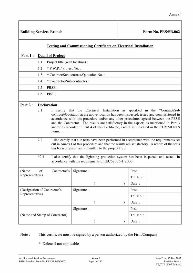
Building Services Branch Form No. PBS/SR.062
Testing and Commissioning Certificate on Electrical Installation
Part 1 : Detail of Project
1.1 Project title (with location) :
1.2 * P.W.P. / Project No. :
1.3 * Contract/Sub-contract/Quotation No. :
1.4 * Contractor/Sub-contractor :
1.5 PBSE :
1.6 PBSI :
Part 2 : Declaration2.1 I certify that the Electrical Installation as specified in the *Contract/Sub
contract//Quotation at the above location has been inspected, tested and commissioned inaccordance with this procedure and/or any other procedures agreed between the PBSEand the Contractor. The results are satisfactory in the aspects as mentioned in Part 3and/or as recorded in Part 4 of this Certificate, except as indicated in the COMMENTSitems.
2.2 I also certify that site tests have been performed in accordance with the requirements setout in Annex I of this procedure and that the results are satisfactory. A record of the testshas been prepared and submitted to the project BSE.
*2.3 I also certify that the lightning protection system has been inspected and tested, inaccordance with the requirements of IEC62305-1:2006.
Signature - Post :
Tel. No. :
(Name of Contractor’sRepresentative)
( ) Date :
Signature - Post :
Tel. No. :
(Designation of Contractor’sRepresentative)
( ) Date :
Signature - Post :
Tel. No. :(Name and Stamp of Contractor)
( ) Date :
Note : This certificate must be signed by a person authorized by the Firm/Company
* Delete if not applicable
Annex I
Signature - Post :
Tel. No. :Tested / Checked by :(Name of Contractor’s Representative)
( ) Date :
Signature - Post :
Tel. No. :Witnessed by :(Name(s) of *PBSE/PBSI)
( ) Date :
Architectural Services Department Annex I Issue Date: 17 Dec 2007BSB– Standard Form No:PBS/SR.062(2007) Page 2 of 40 Revision Date: -
EE_TCP (2007 Edition)
Items tested /checked byContractor
Items witnessedby
PBSE/PBSI
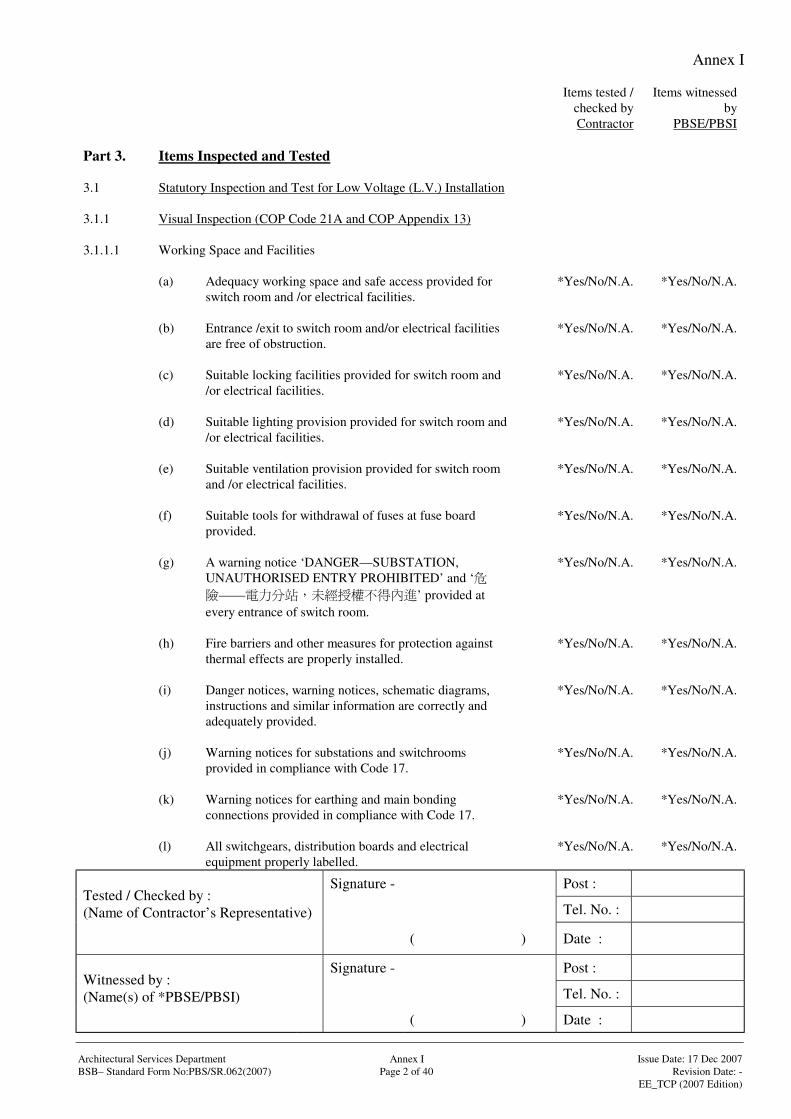
Part 3. Items Inspected and Tested
3.1 Statutory Inspection and Test for Low Voltage (L.V.) Installation
3.1.1 Visual Inspection (COP Code 21A and COP Appendix 13)
3.1.1.1 Working Space and Facilities
(a) Adequacy working space and safe access provided forswitch room and /or electrical facilities.
*Yes/No/N.A. *Yes/No/N.A.
(b) Entrance /exit to switch room and/or electrical facilitiesare free of obstruction.
*Yes/No/N.A. *Yes/No/N.A.
(c) Suitable locking facilities provided for switch room and/or electrical facilities.
*Yes/No/N.A. *Yes/No/N.A.
(d) Suitable lighting provision provided for switch room and/or electrical facilities.
*Yes/No/N.A. *Yes/No/N.A.
(e) Suitable ventilation provision provided for switch roomand /or electrical facilities.
*Yes/No/N.A. *Yes/No/N.A.
(f) Suitable tools for withdrawal of fuses at fuse boardprovided.
*Yes/No/N.A. *Yes/No/N.A.
(g) A warning notice ‘DANGER—SUBSTATION,UNAUTHORISED ENTRY PROHIBITED’ and ‘
—— ’ provided atevery entrance of switch room.
*Yes/No/N.A. *Yes/No/N.A.
(h) Fire barriers and other measures for protection againstthermal effects are properly installed.
*Yes/No/N.A. *Yes/No/N.A.
(i) Danger notices, warning notices, schematic diagrams,instructions and similar information are correctly andadequately provided.
*Yes/No/N.A. *Yes/No/N.A.
(j) Warning notices for substations and switchroomsprovided in compliance with Code 17.
*Yes/No/N.A. *Yes/No/N.A.
(k) Warning notices for earthing and main bondingconnections provided in compliance with Code 17.
*Yes/No/N.A. *Yes/No/N.A.
(l) All switchgears, distribution boards and electricalequipment properly labelled.
*Yes/No/N.A. *Yes/No/N.A.
Annex I
Signature - Post :
Tel. No. :Tested / Checked by :(Name of Contractor’s Representative)
( ) Date :
Signature - Post :
Tel. No. :Witnessed by :(Name(s) of *PBSE/PBSI)
( ) Date :
Architectural Services Department Annex I Issue Date: 17 Dec 2007BSB– Standard Form No:PBS/SR.062(2007) Page 3 of 40 Revision Date: -
EE_TCP (2007 Edition)
Items tested /checked byContractor
Items witnessedby
PBSE/PBSI
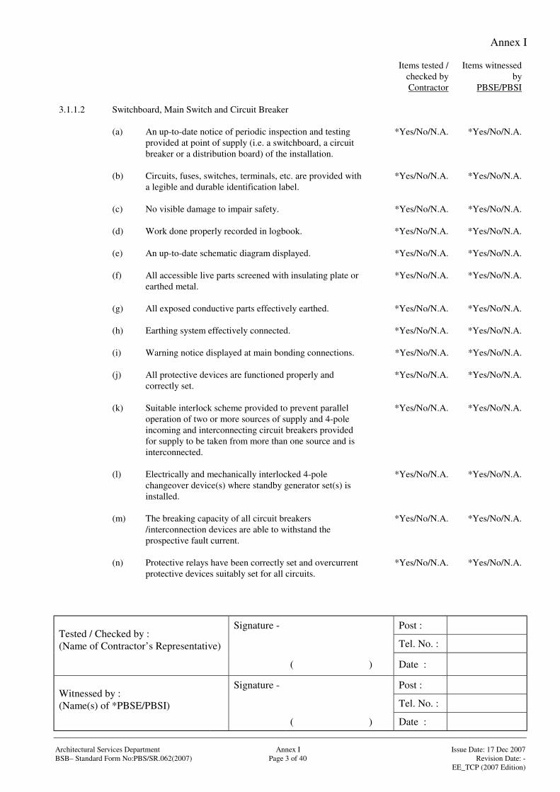
3.1.1.2 Switchboard, Main Switch and Circuit Breaker
(a) An up-to-date notice of periodic inspection and testingprovided at point of supply (i.e. a switchboard, a circuitbreaker or a distribution board) of the installation.
*Yes/No/N.A. *Yes/No/N.A.
(b) Circuits, fuses, switches, terminals, etc. are provided witha legible and durable identification label.
*Yes/No/N.A. *Yes/No/N.A.
(c) No visible damage to impair safety. *Yes/No/N.A. *Yes/No/N.A.
(d) Work done properly recorded in logbook. *Yes/No/N.A. *Yes/No/N.A.
(e) An up-to-date schematic diagram displayed. *Yes/No/N.A. *Yes/No/N.A.
(f) All accessible live parts screened with insulating plate orearthed metal.
*Yes/No/N.A. *Yes/No/N.A.
(g) All exposed conductive parts effectively earthed. *Yes/No/N.A. *Yes/No/N.A.
(h) Earthing system effectively connected. *Yes/No/N.A. *Yes/No/N.A.
(i) Warning notice displayed at main bonding connections. *Yes/No/N.A. *Yes/No/N.A.
(j) All protective devices are functioned properly andcorrectly set.
*Yes/No/N.A. *Yes/No/N.A.
(k) Suitable interlock scheme provided to prevent paralleloperation of two or more sources of supply and 4-poleincoming and interconnecting circuit breakers providedfor supply to be taken from more than one source and isinterconnected.
*Yes/No/N.A. *Yes/No/N.A.
(l) Electrically and mechanically interlocked 4-polechangeover device(s) where standby generator set(s) isinstalled.
*Yes/No/N.A. *Yes/No/N.A.
(m) The breaking capacity of all circuit breakers/interconnection devices are able to withstand theprospective fault current.
*Yes/No/N.A. *Yes/No/N.A.
(n) Protective relays have been correctly set and overcurrentprotective devices suitably set for all circuits.
*Yes/No/N.A. *Yes/No/N.A.
Annex I
Signature - Post :
Tel. No. :Tested / Checked by :(Name of Contractor’s Representative)
( ) Date :
Signature - Post :
Tel. No. :Witnessed by :(Name(s) of *PBSE/PBSI)
( ) Date :
Architectural Services Department Annex I Issue Date: 17 Dec 2007BSB– Standard Form No:PBS/SR.062(2007) Page 4 of 40 Revision Date: -
EE_TCP (2007 Edition)
Items tested /checked byContractor
Items witnessedby
PBSE/PBSI
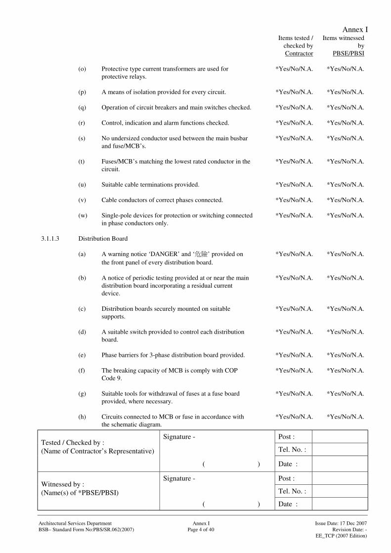
(o) Protective type current transformers are used forprotective relays.
*Yes/No/N.A. *Yes/No/N.A.
(p) A means of isolation provided for every circuit. *Yes/No/N.A. *Yes/No/N.A.
(q) Operation of circuit breakers and main switches checked. *Yes/No/N.A. *Yes/No/N.A.
(r) Control, indication and alarm functions checked. *Yes/No/N.A. *Yes/No/N.A.
(s) No undersized conductor used between the main busbarand fuse/MCB’s.
*Yes/No/N.A. *Yes/No/N.A.
(t) Fuses/MCB’s matching the lowest rated conductor in thecircuit.
*Yes/No/N.A. *Yes/No/N.A.
(u) Suitable cable terminations provided. *Yes/No/N.A. *Yes/No/N.A.
(v) Cable conductors of correct phases connected. *Yes/No/N.A. *Yes/No/N.A.
(w) Single-pole devices for protection or switching connectedin phase conductors only.
*Yes/No/N.A. *Yes/No/N.A.
3.1.1.3 Distribution Board
(a) A warning notice ‘DANGER’ and ‘ ’ provided onthe front panel of every distribution board.
*Yes/No/N.A. *Yes/No/N.A.
(b) A notice of periodic testing provided at or near the maindistribution board incorporating a residual currentdevice.
*Yes/No/N.A. *Yes/No/N.A.
(c) Distribution boards securely mounted on suitablesupports.
*Yes/No/N.A. *Yes/No/N.A.
(d) A suitable switch provided to control each distributionboard.
*Yes/No/N.A. *Yes/No/N.A.
(e) Phase barriers for 3-phase distribution board provided. *Yes/No/N.A. *Yes/No/N.A.
(f) The breaking capacity of MCB is comply with COPCode 9.
*Yes/No/N.A. *Yes/No/N.A.
(g) Suitable tools for withdrawal of fuses at a fuse boardprovided, where necessary.
*Yes/No/N.A. *Yes/No/N.A.
(h) Circuits connected to MCB or fuse in accordance withthe schematic diagram.
*Yes/No/N.A. *Yes/No/N.A.
Annex I
Signature - Post :
Tel. No. :Tested / Checked by :(Name of Contractor’s Representative)
( ) Date :
Signature - Post :
Tel. No. :Witnessed by :(Name(s) of *PBSE/PBSI)
( ) Date :
Architectural Services Department Annex I Issue Date: 17 Dec 2007BSB– Standard Form No:PBS/SR.062(2007) Page 5 of 40 Revision Date: -
EE_TCP (2007 Edition)
Items tested /checked byContractor
Items witnessedby
PBSE/PBSI
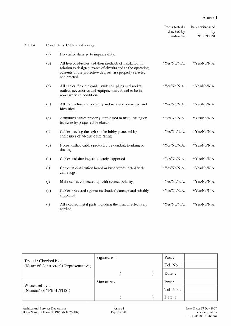
3.1.1.4 Conductors, Cables and wirings
(a) No visible damage to impair safety.
(b) All live conductors and their methods of insulation, inrelation to design currents of circuits and to the operatingcurrents of the protective devices, are properly selectedand erected.
*Yes/No/N.A. *Yes/No/N.A.
(c) All cables, flexible cords, switches, plugs and socketoutlets, accessories and equipment are found to be ingood working conditions.
*Yes/No/N.A. *Yes/No/N.A.
(d) All conductors are correctly and securely connected andidentified.
*Yes/No/N.A. *Yes/No/N.A.
(e) Armoured cables properly terminated to metal casing ortrunking by proper cable glands.
*Yes/No/N.A. *Yes/No/N.A.
(f) Cables passing through smoke lobby protected byenclosures of adequate fire rating.
*Yes/No/N.A. *Yes/No/N.A.
(g) Non-sheathed cables protected by conduit, trunking orducting.
*Yes/No/N.A. *Yes/No/N.A.
(h) Cables and ductings adequately supported. *Yes/No/N.A. *Yes/No/N.A.
(i) Cables at distribution board or busbar terminated withcable lugs.
*Yes/No/N.A. *Yes/No/N.A.
(j) Main cables connected up with correct polarity. *Yes/No/N.A. *Yes/No/N.A.
(k) Cables protected against mechanical damage and suitablysupported.
*Yes/No/N.A. *Yes/No/N.A.
(l) All exposed metal parts including the armour effectivelyearthed.
*Yes/No/N.A. *Yes/No/N.A.
Annex I
Signature - Post :
Tel. No. :Tested / Checked by :(Name of Contractor’s Representative)
( ) Date :
Signature - Post :
Tel. No. :Witnessed by :(Name(s) of *PBSE/PBSI)
( ) Date :
Architectural Services Department Annex I Issue Date: 17 Dec 2007BSB– Standard Form No:PBS/SR.062(2007) Page 6 of 40 Revision Date: -
EE_TCP (2007 Edition)
Items tested /checked byContractor
Items witnessedby
PBSE/PBSI
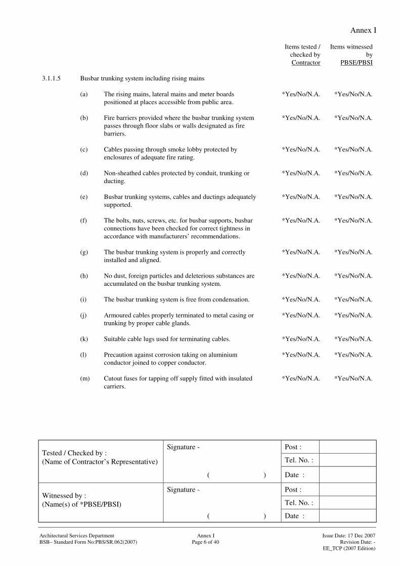
3.1.1.5 Busbar trunking system including rising mains
(a) The rising mains, lateral mains and meter boardspositioned at places accessible from public area.
*Yes/No/N.A. *Yes/No/N.A.
(b) Fire barriers provided where the busbar trunking systempasses through floor slabs or walls designated as firebarriers.
*Yes/No/N.A. *Yes/No/N.A.
(c) Cables passing through smoke lobby protected byenclosures of adequate fire rating.
*Yes/No/N.A. *Yes/No/N.A.
(d) Non-sheathed cables protected by conduit, trunking orducting.
*Yes/No/N.A. *Yes/No/N.A.
(e) Busbar trunking systems, cables and ductings adequatelysupported.
*Yes/No/N.A. *Yes/No/N.A.
(f) The bolts, nuts, screws, etc. for busbar supports, busbarconnections have been checked for correct tightness inaccordance with manufacturers’ recommendations.
*Yes/No/N.A. *Yes/No/N.A.
(g) The busbar trunking system is properly and correctlyinstalled and aligned.
*Yes/No/N.A. *Yes/No/N.A.
(h) No dust, foreign particles and deleterious substances areaccumulated on the busbar trunking system.
*Yes/No/N.A. *Yes/No/N.A.
(i) The busbar trunking system is free from condensation. *Yes/No/N.A. *Yes/No/N.A.
(j) Armoured cables properly terminated to metal casing ortrunking by proper cable glands.
*Yes/No/N.A. *Yes/No/N.A.
(k) Suitable cable lugs used for terminating cables. *Yes/No/N.A. *Yes/No/N.A.
(l) Precaution against corrosion taking on aluminiumconductor joined to copper conductor.
*Yes/No/N.A. *Yes/No/N.A.
(m) Cutout fuses for tapping off supply fitted with insulatedcarriers.
*Yes/No/N.A. *Yes/No/N.A.
Annex I
Signature - Post :
Tel. No. :Tested / Checked by :(Name of Contractor’s Representative)
( ) Date :
Signature - Post :
Tel. No. :Witnessed by :(Name(s) of *PBSE/PBSI)
( ) Date :
Architectural Services Department Annex I Issue Date: 17 Dec 2007BSB– Standard Form No:PBS/SR.062(2007) Page 7 of 40 Revision Date: -
EE_TCP (2007 Edition)
Items tested /checked byContractor
Items witnessedby
PBSE/PBSI
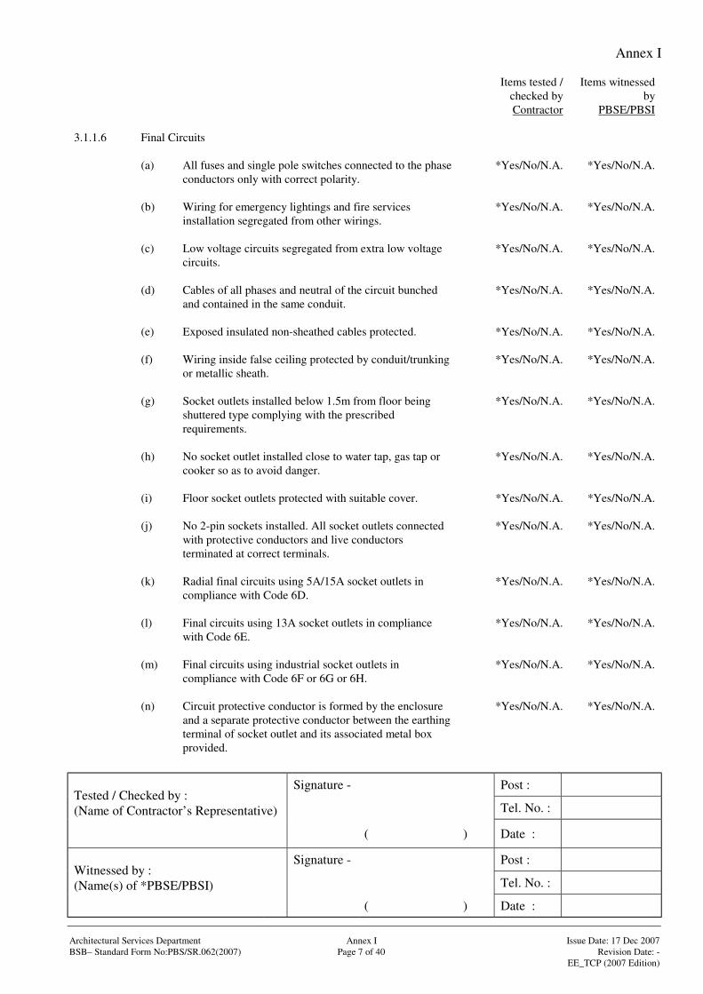
3.1.1.6 Final Circuits
(a) All fuses and single pole switches connected to the phaseconductors only with correct polarity.
*Yes/No/N.A. *Yes/No/N.A.
(b) Wiring for emergency lightings and fire servicesinstallation segregated from other wirings.
*Yes/No/N.A. *Yes/No/N.A.
(c) Low voltage circuits segregated from extra low voltagecircuits.
*Yes/No/N.A. *Yes/No/N.A.
(d) Cables of all phases and neutral of the circuit bunchedand contained in the same conduit.
*Yes/No/N.A. *Yes/No/N.A.
(e) Exposed insulated non-sheathed cables protected. *Yes/No/N.A. *Yes/No/N.A.
(f) Wiring inside false ceiling protected by conduit/trunkingor metallic sheath.
*Yes/No/N.A. *Yes/No/N.A.
(g) Socket outlets installed below 1.5m from floor beingshuttered type complying with the prescribedrequirements.
*Yes/No/N.A. *Yes/No/N.A.
(h) No socket outlet installed close to water tap, gas tap orcooker so as to avoid danger.
*Yes/No/N.A. *Yes/No/N.A.
(i) Floor socket outlets protected with suitable cover. *Yes/No/N.A. *Yes/No/N.A.
(j) No 2-pin sockets installed. All socket outlets connectedwith protective conductors and live conductorsterminated at correct terminals.
*Yes/No/N.A. *Yes/No/N.A.
(k) Radial final circuits using 5A/15A socket outlets incompliance with Code 6D.
*Yes/No/N.A. *Yes/No/N.A.
(l) Final circuits using 13A socket outlets in compliancewith Code 6E.
*Yes/No/N.A. *Yes/No/N.A.
(m) Final circuits using industrial socket outlets incompliance with Code 6F or 6G or 6H.
*Yes/No/N.A. *Yes/No/N.A.
(n) Circuit protective conductor is formed by the enclosureand a separate protective conductor between the earthingterminal of socket outlet and its associated metal boxprovided.
*Yes/No/N.A. *Yes/No/N.A.
Annex I
Signature - Post :
Tel. No. :Tested / Checked by :(Name of Contractor’s Representative)
( ) Date :
Signature - Post :
Tel. No. :Witnessed by :(Name(s) of *PBSE/PBSI)
( ) Date :
Architectural Services Department Annex I Issue Date: 17 Dec 2007BSB– Standard Form No:PBS/SR.062(2007) Page 8 of 40 Revision Date: -
EE_TCP (2007 Edition)
Items tested /checked byContractor
Items witnessedby
PBSE/PBSI
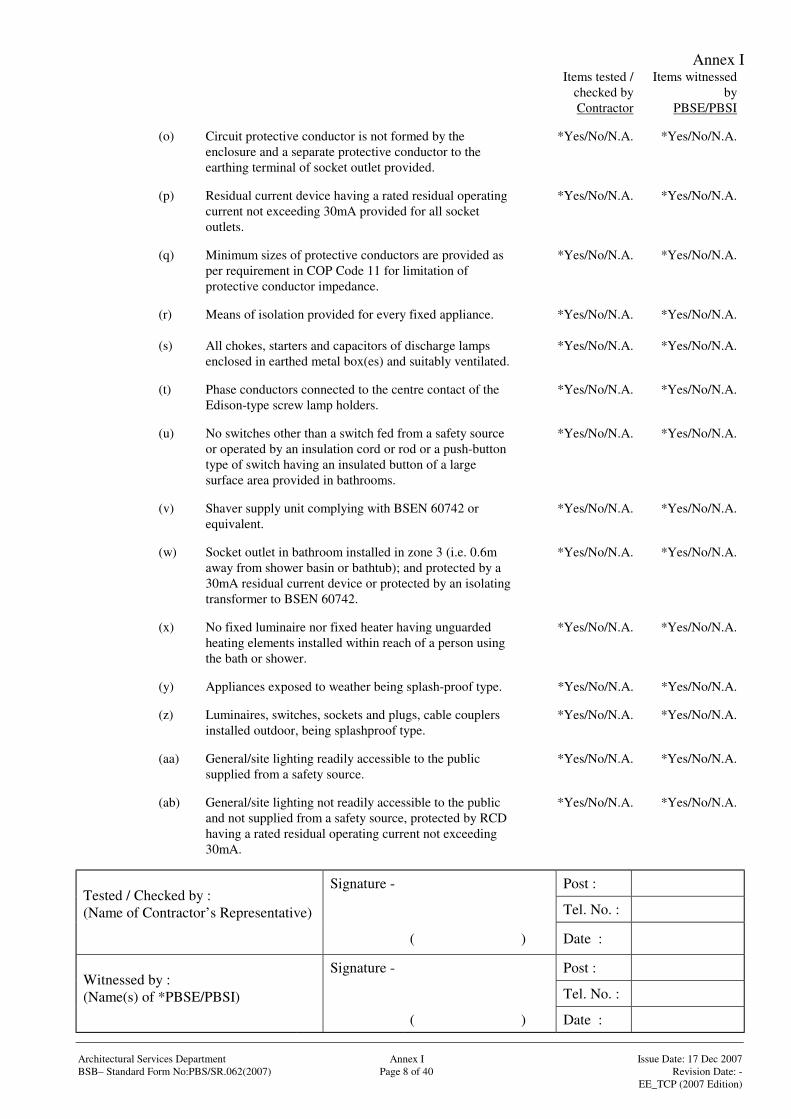
(o) Circuit protective conductor is not formed by theenclosure and a separate protective conductor to theearthing terminal of socket outlet provided.
*Yes/No/N.A. *Yes/No/N.A.
(p) Residual current device having a rated residual operatingcurrent not exceeding 30mA provided for all socketoutlets.
*Yes/No/N.A. *Yes/No/N.A.
(q) Minimum sizes of protective conductors are provided asper requirement in COP Code 11 for limitation ofprotective conductor impedance.
*Yes/No/N.A. *Yes/No/N.A.
(r) Means of isolation provided for every fixed appliance. *Yes/No/N.A. *Yes/No/N.A.
(s) All chokes, starters and capacitors of discharge lampsenclosed in earthed metal box(es) and suitably ventilated.
*Yes/No/N.A. *Yes/No/N.A.
(t) Phase conductors connected to the centre contact of theEdison-type screw lamp holders.
*Yes/No/N.A. *Yes/No/N.A.
(u) No switches other than a switch fed from a safety sourceor operated by an insulation cord or rod or a push-buttontype of switch having an insulated button of a largesurface area provided in bathrooms.
*Yes/No/N.A. *Yes/No/N.A.
(v) Shaver supply unit complying with BSEN 60742 orequivalent.
*Yes/No/N.A. *Yes/No/N.A.
(w) Socket outlet in bathroom installed in zone 3 (i.e. 0.6maway from shower basin or bathtub); and protected by a30mA residual current device or protected by an isolatingtransformer to BSEN 60742.
*Yes/No/N.A. *Yes/No/N.A.
(x) No fixed luminaire nor fixed heater having unguardedheating elements installed within reach of a person usingthe bath or shower.
*Yes/No/N.A. *Yes/No/N.A.
(y) Appliances exposed to weather being splash-proof type. *Yes/No/N.A. *Yes/No/N.A.
(z) Luminaires, switches, sockets and plugs, cable couplersinstalled outdoor, being splashproof type.
*Yes/No/N.A. *Yes/No/N.A.
(aa) General/site lighting readily accessible to the publicsupplied from a safety source.
*Yes/No/N.A. *Yes/No/N.A.
(ab) General/site lighting not readily accessible to the publicand not supplied from a safety source, protected by RCDhaving a rated residual operating current not exceeding30mA.
*Yes/No/N.A. *Yes/No/N.A.
Annex I
Signature - Post :
Tel. No. :Tested / Checked by :(Name of Contractor’s Representative)
( ) Date :
Signature - Post :
Tel. No. :Witnessed by :(Name(s) of *PBSE/PBSI)
( ) Date :
Architectural Services Department Annex I Issue Date: 17 Dec 2007BSB– Standard Form No:PBS/SR.062(2007) Page 9 of 40 Revision Date: -
EE_TCP (2007 Edition)
Items tested /checked byContractor
Items witnessedby
PBSE/PBSI
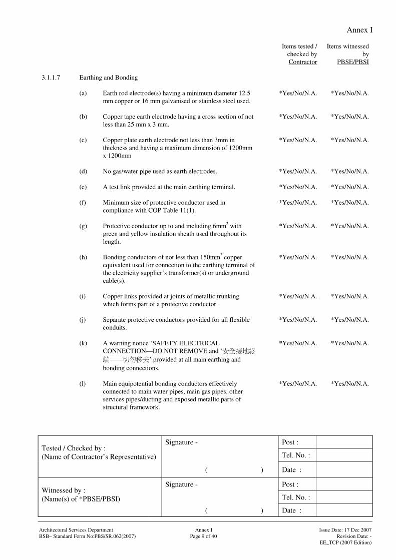
3.1.1.7 Earthing and Bonding
(a) Earth rod electrode(s) having a minimum diameter 12.5mm copper or 16 mm galvanised or stainless steel used.
*Yes/No/N.A. *Yes/No/N.A.
(b) Copper tape earth electrode having a cross section of notless than 25 mm x 3 mm.
*Yes/No/N.A. *Yes/No/N.A.
(c) Copper plate earth electrode not less than 3mm inthickness and having a maximum dimension of 1200mmx 1200mm
*Yes/No/N.A. *Yes/No/N.A.
(d) No gas/water pipe used as earth electrodes. *Yes/No/N.A. *Yes/No/N.A.
(e) A test link provided at the main earthing terminal. *Yes/No/N.A. *Yes/No/N.A.
(f) Minimum size of protective conductor used incompliance with COP Table 11(1).
*Yes/No/N.A. *Yes/No/N.A.
(g) Protective conductor up to and including 6mm2 withgreen and yellow insulation sheath used throughout itslength.
*Yes/No/N.A. *Yes/No/N.A.
(h) Bonding conductors of not less than 150mm2 copperequivalent used for connection to the earthing terminal ofthe electricity supplier’s transformer(s) or undergroundcable(s).
*Yes/No/N.A. *Yes/No/N.A.
(i) Copper links provided at joints of metallic trunkingwhich forms part of a protective conductor.
*Yes/No/N.A. *Yes/No/N.A.
(j) Separate protective conductors provided for all flexibleconduits.
*Yes/No/N.A. *Yes/No/N.A.
(k) A warning notice ‘SAFETY ELECTRICALCONNECTION—DO NOT REMOVE and ‘
—— ’ provided at all main earthing andbonding connections.
*Yes/No/N.A. *Yes/No/N.A.
(l) Main equipotential bonding conductors effectivelyconnected to main water pipes, main gas pipes, otherservices pipes/ducting and exposed metallic parts ofstructural framework.
*Yes/No/N.A. *Yes/No/N.A.
Annex I
Signature - Post :
Tel. No. :Tested / Checked by :(Name of Contractor’s Representative)
( ) Date :
Signature - Post :
Tel. No. :Witnessed by :(Name(s) of *PBSE/PBSI)
( ) Date :
Architectural Services Department Annex I Issue Date: 17 Dec 2007BSB– Standard Form No:PBS/SR.062(2007) Page 10 of 40 Revision Date: -
EE_TCP (2007 Edition)
Items tested /checked byContractor
Items witnessedby
PBSE/PBSI
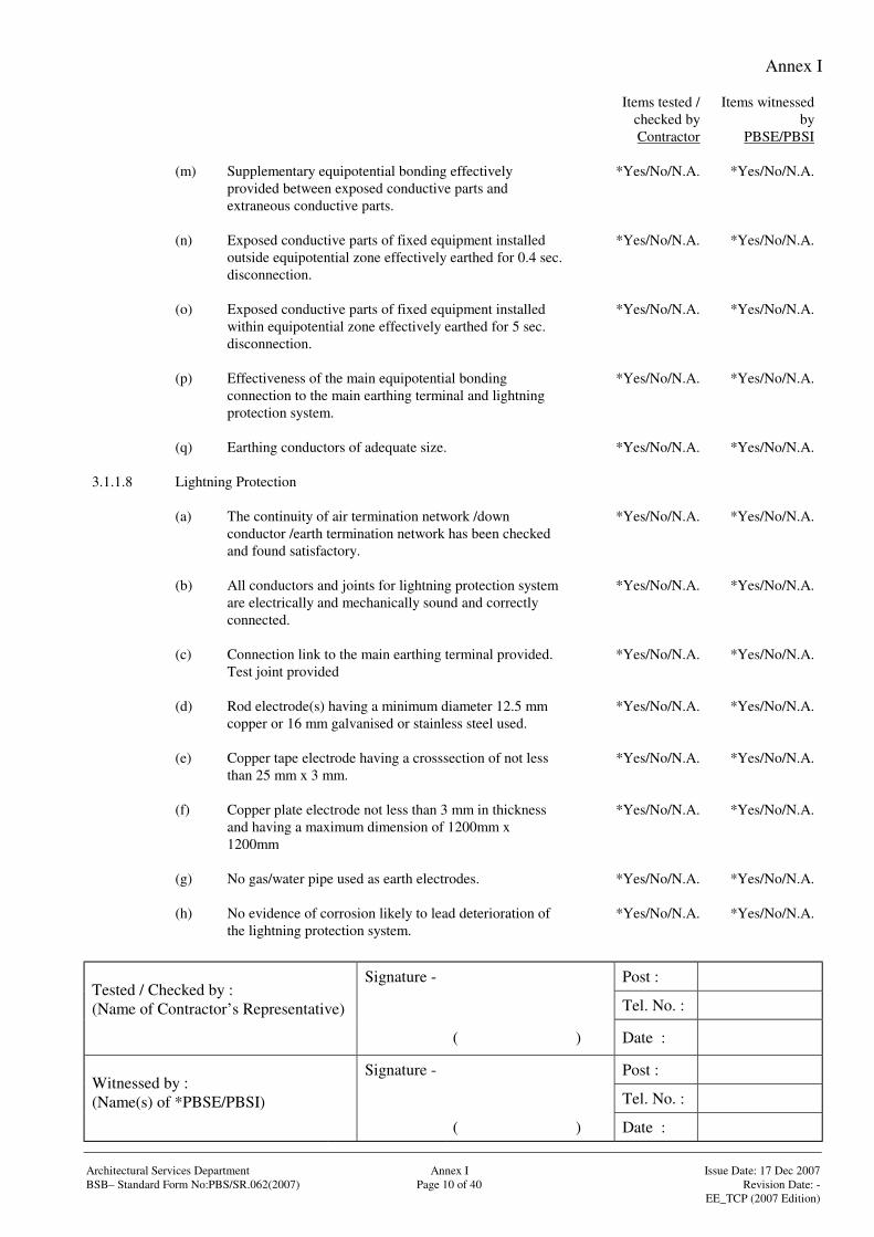
(m) Supplementary equipotential bonding effectivelyprovided between exposed conductive parts andextraneous conductive parts.
*Yes/No/N.A. *Yes/No/N.A.
(n) Exposed conductive parts of fixed equipment installedoutside equipotential zone effectively earthed for 0.4 sec.disconnection.
*Yes/No/N.A. *Yes/No/N.A.
(o) Exposed conductive parts of fixed equipment installedwithin equipotential zone effectively earthed for 5 sec.disconnection.
*Yes/No/N.A. *Yes/No/N.A.
(p) Effectiveness of the main equipotential bondingconnection to the main earthing terminal and lightningprotection system.
*Yes/No/N.A. *Yes/No/N.A.
(q) Earthing conductors of adequate size. *Yes/No/N.A. *Yes/No/N.A.
3.1.1.8 Lightning Protection
(a) The continuity of air termination network /downconductor /earth termination network has been checkedand found satisfactory.
*Yes/No/N.A. *Yes/No/N.A.
(b) All conductors and joints for lightning protection systemare electrically and mechanically sound and correctlyconnected.
*Yes/No/N.A. *Yes/No/N.A.
(c) Connection link to the main earthing terminal provided.Test joint provided
*Yes/No/N.A. *Yes/No/N.A.
(d) Rod electrode(s) having a minimum diameter 12.5 mmcopper or 16 mm galvanised or stainless steel used.
*Yes/No/N.A. *Yes/No/N.A.
(e) Copper tape electrode having a crosssection of not lessthan 25 mm x 3 mm.
*Yes/No/N.A. *Yes/No/N.A.
(f) Copper plate electrode not less than 3 mm in thicknessand having a maximum dimension of 1200mm x1200mm
*Yes/No/N.A. *Yes/No/N.A.
(g) No gas/water pipe used as earth electrodes. *Yes/No/N.A. *Yes/No/N.A.
(h) No evidence of corrosion likely to lead deterioration ofthe lightning protection system.
*Yes/No/N.A. *Yes/No/N.A.
Annex I
Signature - Post :
Tel. No. :Tested / Checked by :(Name of Contractor’s Representative)
( ) Date :
Signature - Post :
Tel. No. :Witnessed by :(Name(s) of *PBSE/PBSI)
( ) Date :
Architectural Services Department Annex I Issue Date: 17 Dec 2007BSB– Standard Form No:PBS/SR.062(2007) Page 11 of 40 Revision Date: -
EE_TCP (2007 Edition)
Items tested /checked byContractor
Items witnessedby
PBSE/PBSI
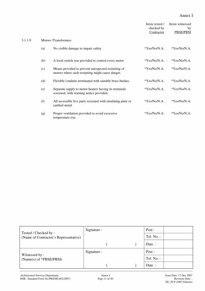
3.1.1.9 Motors /Transformers
(a) No visible damage to impair safety. *Yes/No/N.A. *Yes/No/N.A.
(b) A local switch was provided to control every motor *Yes/No/N.A. *Yes/No/N.A.
(c) Means provided to prevent unexpected restarting ofmotors where such restarting might cause danger.
*Yes/No/N.A. *Yes/No/N.A.
(d) Flexible conduits terminated with suitable brass bushes. *Yes/No/N.A. *Yes/No/N.A.
(e) Separate supply to motor heaters having its terminalsscreened, with warning notice provided.
*Yes/No/N.A. *Yes/No/N.A.
(f) All accessible live parts screened with insulating plate orearthed metal.
*Yes/No/N.A. *Yes/No/N.A.
(g) Proper ventilation provided to avoid excessivetemperature rise.
*Yes/No/N.A. *Yes/No/N.A.
Annex I
Signature - Post :
Tel. No. :Tested / Checked by :(Name of Contractor’s Representative)
( ) Date :
Signature - Post :
Tel. No. :Witnessed by :(Name(s) of *PBSE/PBSI)
( ) Date :
Architectural Services Department Annex I Issue Date: 17 Dec 2007BSB– Standard Form No:PBS/SR.062(2007) Page 12 of 40 Revision Date: -
EE_TCP (2007 Edition)
Items tested /checked byContractor
Items witnessedby
PBSE/PBSI
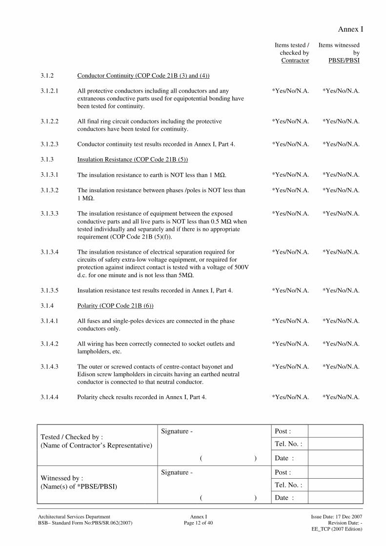
3.1.2 Conductor Continuity (COP Code 21B (3) and (4))
3.1.2.1 All protective conductors including all conductors and anyextraneous conductive parts used for equipotential bonding havebeen tested for continuity.
*Yes/No/N.A. *Yes/No/N.A.
3.1.2.2 All final ring circuit conductors including the protectiveconductors have been tested for continuity.
*Yes/No/N.A. *Yes/No/N.A.
3.1.2.3 Conductor continuity test results recorded in Annex I, Part 4. *Yes/No/N.A. *Yes/No/N.A.
3.1.3 Insulation Resistance (COP Code 21B (5))
3.1.3.1 The insulation resistance to earth is NOT less than 1 MΩ. *Yes/No/N.A. *Yes/No/N.A.
3.1.3.2 The insulation resistance between phases /poles is NOT less than1 MΩ.
*Yes/No/N.A. *Yes/No/N.A.
3.1.3.3 The insulation resistance of equipment between the exposedconductive parts and all live parts is NOT less than 0.5 MΩ whentested individually and separately and if there is no appropriaterequirement (COP Code 21B (5)(f)).
*Yes/No/N.A. *Yes/No/N.A.
3.1.3.4 The insulation resistance of electrical separation required forcircuits of safety extra-low voltage equipment, or required forprotection against indirect contact is tested with a voltage of 500Vd.c. for one minute and is not less than 5MΩ.
*Yes/No/N.A. *Yes/No/N.A.
3.1.3.5 Insulation resistance test results recorded in Annex I, Part 4. *Yes/No/N.A. *Yes/No/N.A.
3.1.4 Polarity (COP Code 21B (6))
3.1.4.1 All fuses and single-poles devices are connected in the phaseconductors only.
*Yes/No/N.A. *Yes/No/N.A.
3.1.4.2 All wiring has been correctly connected to socket outlets andlampholders, etc.
*Yes/No/N.A. *Yes/No/N.A.
3.1.4.3 The outer or screwed contacts of centre-contact bayonet andEdison screw lampholders in circuits having an earthed neutralconductor is connected to that neutral conductor.
*Yes/No/N.A. *Yes/No/N.A.
3.1.4.4 Polarity check results recorded in Annex I, Part 4. *Yes/No/N.A. *Yes/No/N.A.
Annex I
Signature - Post :
Tel. No. :Tested / Checked by :(Name of Contractor’s Representative)
( ) Date :
Signature - Post :
Tel. No. :Witnessed by :(Name(s) of *PBSE/PBSI)
( ) Date :
Architectural Services Department Annex I Issue Date: 17 Dec 2007BSB– Standard Form No:PBS/SR.062(2007) Page 13 of 40 Revision Date: -
EE_TCP (2007 Edition)
Items tested /checked byContractor
Items witnessedby
PBSE/PBSI
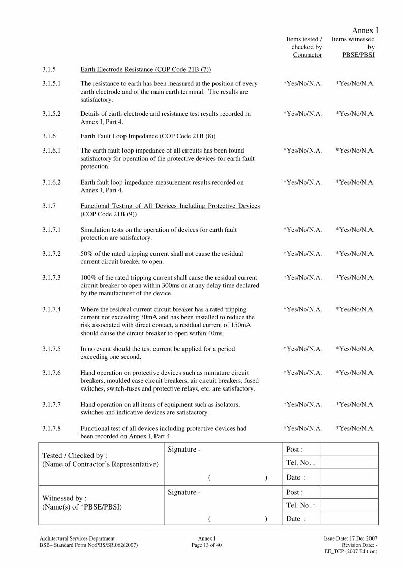
3.1.5 Earth Electrode Resistance (COP Code 21B (7))
3.1.5.1 The resistance to earth has been measured at the position of everyearth electrode and of the main earth terminal. The results aresatisfactory.
*Yes/No/N.A. *Yes/No/N.A.
3.1.5.2 Details of earth electrode and resistance test results recorded inAnnex I, Part 4.
*Yes/No/N.A. *Yes/No/N.A.
3.1.6 Earth Fault Loop Impedance (COP Code 21B (8))
3.1.6.1 The earth fault loop impedance of all circuits has been foundsatisfactory for operation of the protective devices for earth faultprotection.
*Yes/No/N.A. *Yes/No/N.A.
3.1.6.2 Earth fault loop impedance measurement results recorded onAnnex I, Part 4.
*Yes/No/N.A. *Yes/No/N.A.
3.1.7 Functional Testing of All Devices Including Protective Devices(COP Code 21B (9))
3.1.7.1 Simulation tests on the operation of devices for earth faultprotection are satisfactory.
*Yes/No/N.A. *Yes/No/N.A.
3.1.7.2 50% of the rated tripping current shall not cause the residualcurrent circuit breaker to open.
*Yes/No/N.A. *Yes/No/N.A.
3.1.7.3 100% of the rated tripping current shall cause the residual currentcircuit breaker to open within 300ms or at any delay time declaredby the manufacturer of the device.
*Yes/No/N.A. *Yes/No/N.A.
3.1.7.4 Where the residual current circuit breaker has a rated trippingcurrent not exceeding 30mA and has been installed to reduce therisk associated with direct contact, a residual current of 150mAshould cause the circuit breaker to open within 40ms.
*Yes/No/N.A. *Yes/No/N.A.
3.1.7.5 In no event should the test current be applied for a periodexceeding one second.
*Yes/No/N.A. *Yes/No/N.A.
3.1.7.6 Hand operation on protective devices such as miniature circuitbreakers, moulded case circuit breakers, air circuit breakers, fusedswitches, switch-fuses and protective relays, etc. are satisfactory.
*Yes/No/N.A. *Yes/No/N.A.
3.1.7.7 Hand operation on all items of equipment such as isolators,switches and indicative devices are satisfactory.
*Yes/No/N.A. *Yes/No/N.A.
3.1.7.8 Functional test of all devices including protective devices hadbeen recorded on Annex I, Part 4.
*Yes/No/N.A. *Yes/No/N.A.
Annex I
Signature - Post :
Tel. No. :Tested / Checked by :(Name of Contractor’s Representative)
( ) Date :
Signature - Post :
Tel. No. :Witnessed by :(Name(s) of *PBSE/PBSI)
( ) Date :
Architectural Services Department Annex I Issue Date: 17 Dec 2007BSB– Standard Form No:PBS/SR.062(2007) Page 14 of 40 Revision Date: -
EE_TCP (2007 Edition)
Items tested /checked byContractor
Items witnessedby
PBSE/PBSI
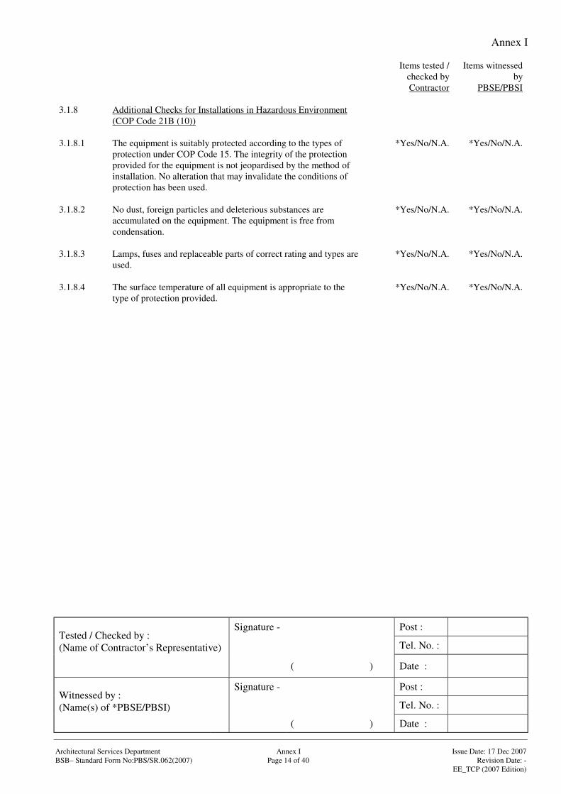
3.1.8 Additional Checks for Installations in Hazardous Environment(COP Code 21B (10))
3.1.8.1 The equipment is suitably protected according to the types ofprotection under COP Code 15. The integrity of the protectionprovided for the equipment is not jeopardised by the method ofinstallation. No alteration that may invalidate the conditions ofprotection has been used.
*Yes/No/N.A. *Yes/No/N.A.
3.1.8.2 No dust, foreign particles and deleterious substances areaccumulated on the equipment. The equipment is free fromcondensation.
*Yes/No/N.A. *Yes/No/N.A.
3.1.8.3 Lamps, fuses and replaceable parts of correct rating and types areused.
*Yes/No/N.A. *Yes/No/N.A.
3.1.8.4 The surface temperature of all equipment is appropriate to thetype of protection provided.
*Yes/No/N.A. *Yes/No/N.A.
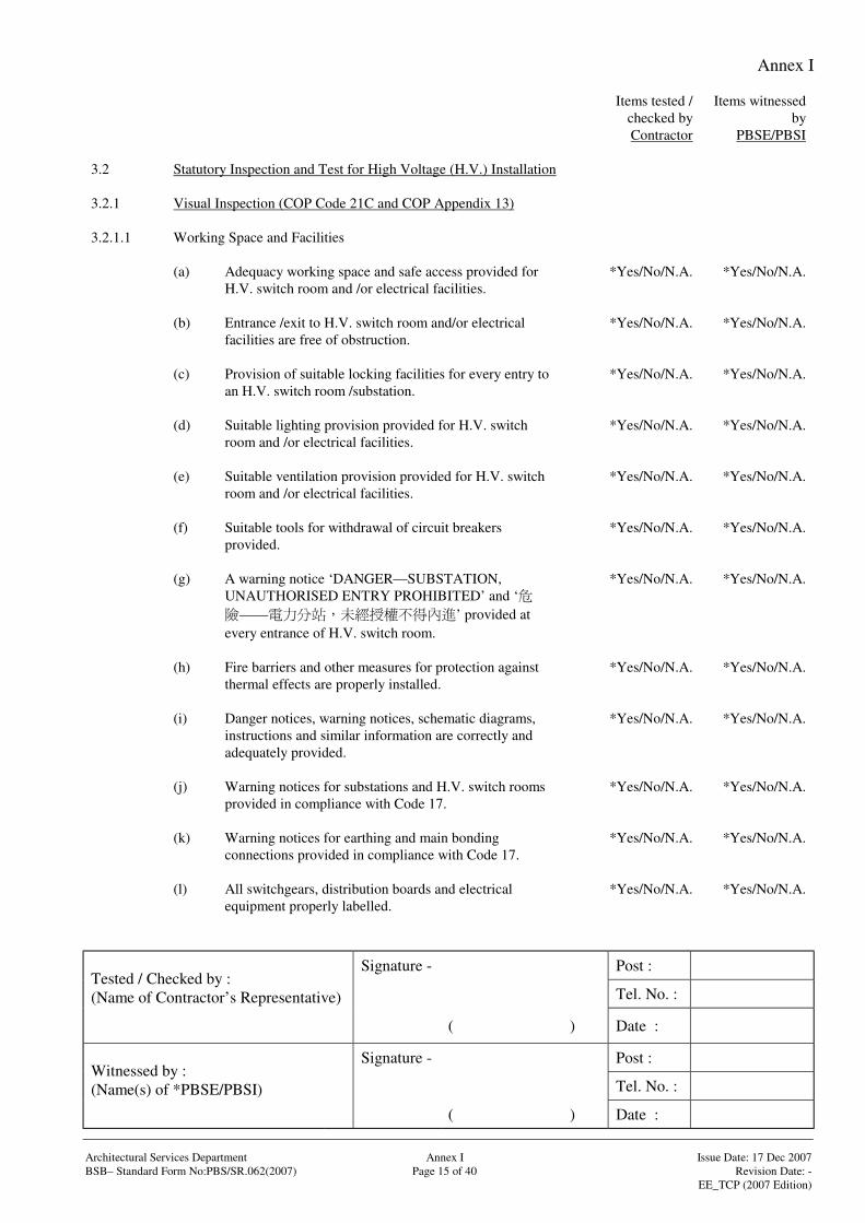
Annex I
Signature - Post :
Tel. No. :Tested / Checked by :(Name of Contractor’s Representative)
( ) Date :
Signature - Post :
Tel. No. :Witnessed by :(Name(s) of *PBSE/PBSI)
( ) Date :
Architectural Services Department Annex I Issue Date: 17 Dec 2007BSB– Standard Form No:PBS/SR.062(2007) Page 15 of 40 Revision Date: -
EE_TCP (2007 Edition)
Items tested /checked byContractor
Items witnessedby
PBSE/PBSI
3.2 Statutory Inspection and Test for High Voltage (H.V.) Installation
3.2.1 Visual Inspection (COP Code 21C and COP Appendix 13)
3.2.1.1 Working Space and Facilities
(a) Adequacy working space and safe access provided forH.V. switch room and /or electrical facilities.
*Yes/No/N.A. *Yes/No/N.A.
(b) Entrance /exit to H.V. switch room and/or electricalfacilities are free of obstruction.
*Yes/No/N.A. *Yes/No/N.A.
(c) Provision of suitable locking facilities for every entry toan H.V. switch room /substation.
*Yes/No/N.A. *Yes/No/N.A.
(d) Suitable lighting provision provided for H.V. switchroom and /or electrical facilities.
*Yes/No/N.A. *Yes/No/N.A.
(e) Suitable ventilation provision provided for H.V. switchroom and /or electrical facilities.
*Yes/No/N.A. *Yes/No/N.A.
(f) Suitable tools for withdrawal of circuit breakersprovided.
*Yes/No/N.A. *Yes/No/N.A.
(g) A warning notice ‘DANGER—SUBSTATION,UNAUTHORISED ENTRY PROHIBITED’ and ‘
—— ’ provided atevery entrance of H.V. switch room.
*Yes/No/N.A. *Yes/No/N.A.
(h) Fire barriers and other measures for protection againstthermal effects are properly installed.
*Yes/No/N.A. *Yes/No/N.A.
(i) Danger notices, warning notices, schematic diagrams,instructions and similar information are correctly andadequately provided.
*Yes/No/N.A. *Yes/No/N.A.
(j) Warning notices for substations and H.V. switch roomsprovided in compliance with Code 17.
*Yes/No/N.A. *Yes/No/N.A.
(k) Warning notices for earthing and main bondingconnections provided in compliance with Code 17.
*Yes/No/N.A. *Yes/No/N.A.
(l) All switchgears, distribution boards and electricalequipment properly labelled.
*Yes/No/N.A. *Yes/No/N.A.
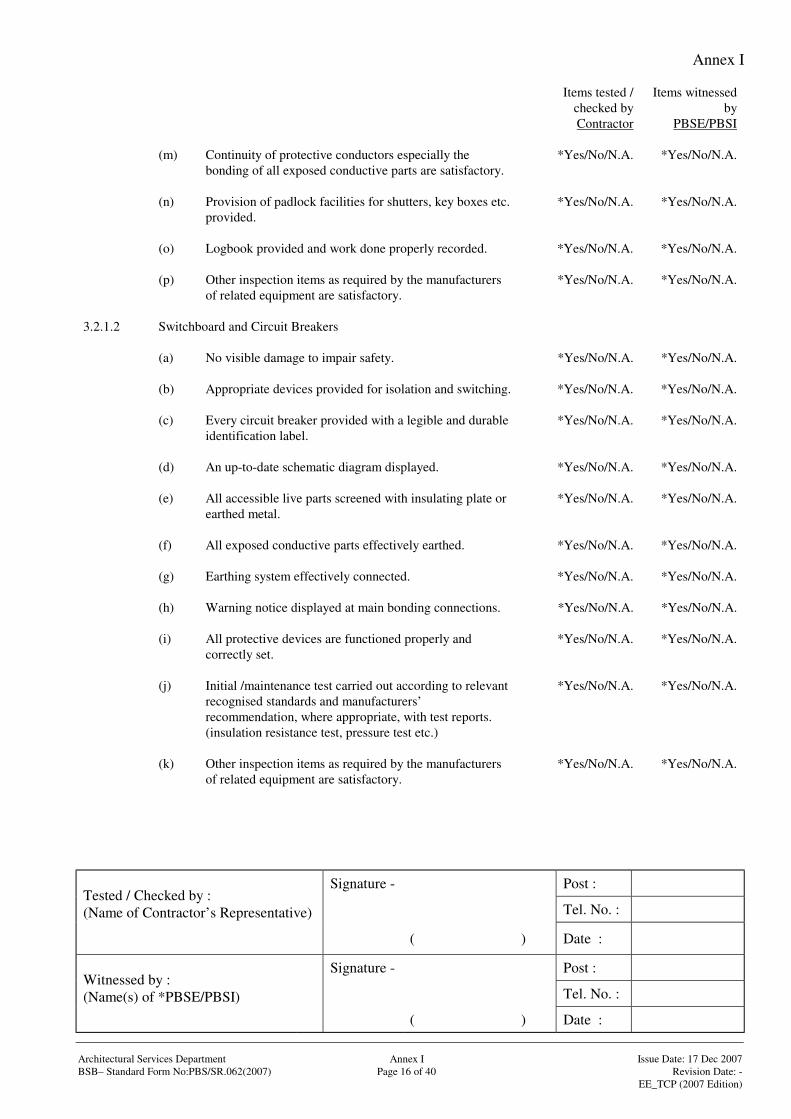
Annex I
Signature - Post :
Tel. No. :Tested / Checked by :(Name of Contractor’s Representative)
( ) Date :
Signature - Post :
Tel. No. :Witnessed by :(Name(s) of *PBSE/PBSI)
( ) Date :
Architectural Services Department Annex I Issue Date: 17 Dec 2007BSB– Standard Form No:PBS/SR.062(2007) Page 16 of 40 Revision Date: -
EE_TCP (2007 Edition)
Items tested /checked byContractor
Items witnessedby
PBSE/PBSI
(m) Continuity of protective conductors especially thebonding of all exposed conductive parts are satisfactory.
*Yes/No/N.A. *Yes/No/N.A.
(n) Provision of padlock facilities for shutters, key boxes etc.provided.
*Yes/No/N.A. *Yes/No/N.A.
(o) Logbook provided and work done properly recorded. *Yes/No/N.A. *Yes/No/N.A.
(p) Other inspection items as required by the manufacturersof related equipment are satisfactory.
*Yes/No/N.A. *Yes/No/N.A.
3.2.1.2 Switchboard and Circuit Breakers
(a) No visible damage to impair safety. *Yes/No/N.A. *Yes/No/N.A.
(b) Appropriate devices provided for isolation and switching. *Yes/No/N.A. *Yes/No/N.A.
(c) Every circuit breaker provided with a legible and durableidentification label.
*Yes/No/N.A. *Yes/No/N.A.
(d) An up-to-date schematic diagram displayed. *Yes/No/N.A. *Yes/No/N.A.
(e) All accessible live parts screened with insulating plate orearthed metal.
*Yes/No/N.A. *Yes/No/N.A.
(f) All exposed conductive parts effectively earthed. *Yes/No/N.A. *Yes/No/N.A.
(g) Earthing system effectively connected. *Yes/No/N.A. *Yes/No/N.A.
(h) Warning notice displayed at main bonding connections. *Yes/No/N.A. *Yes/No/N.A.
(i) All protective devices are functioned properly andcorrectly set.
*Yes/No/N.A. *Yes/No/N.A.
(j) Initial /maintenance test carried out according to relevantrecognised standards and manufacturers’recommendation, where appropriate, with test reports.(insulation resistance test, pressure test etc.)
*Yes/No/N.A. *Yes/No/N.A.
(k) Other inspection items as required by the manufacturersof related equipment are satisfactory.
*Yes/No/N.A. *Yes/No/N.A.
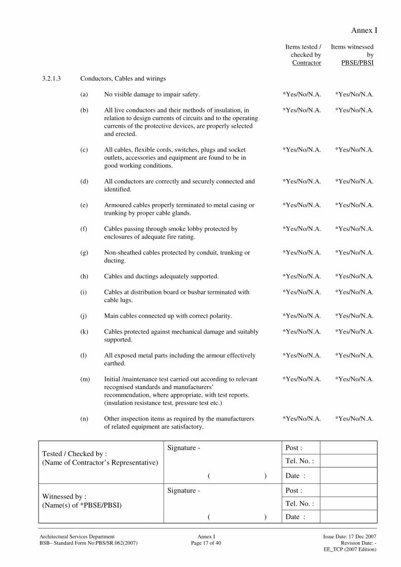
Annex I
Signature - Post :
Tel. No. :Tested / Checked by :(Name of Contractor’s Representative)
( ) Date :
Signature - Post :
Tel. No. :Witnessed by :(Name(s) of *PBSE/PBSI)
( ) Date :
Architectural Services Department Annex I Issue Date: 17 Dec 2007BSB– Standard Form No:PBS/SR.062(2007) Page 17 of 40 Revision Date: -
EE_TCP (2007 Edition)
Items tested /checked byContractor
Items witnessedby
PBSE/PBSI
3.2.1.3 Conductors, Cables and wirings
(a) No visible damage to impair safety. *Yes/No/N.A. *Yes/No/N.A.
(b) All live conductors and their methods of insulation, inrelation to design currents of circuits and to the operatingcurrents of the protective devices, are properly selectedand erected.
*Yes/No/N.A. *Yes/No/N.A.
(c) All cables, flexible cords, switches, plugs and socketoutlets, accessories and equipment are found to be ingood working conditions.
*Yes/No/N.A. *Yes/No/N.A.
(d) All conductors are correctly and securely connected andidentified.
*Yes/No/N.A. *Yes/No/N.A.
(e) Armoured cables properly terminated to metal casing ortrunking by proper cable glands.
*Yes/No/N.A. *Yes/No/N.A.
(f) Cables passing through smoke lobby protected byenclosures of adequate fire rating.
*Yes/No/N.A. *Yes/No/N.A.
(g) Non-sheathed cables protected by conduit, trunking orducting.
*Yes/No/N.A. *Yes/No/N.A.
(h) Cables and ductings adequately supported. *Yes/No/N.A. *Yes/No/N.A.
(i) Cables at distribution board or busbar terminated withcable lugs.
*Yes/No/N.A. *Yes/No/N.A.
(j) Main cables connected up with correct polarity. *Yes/No/N.A. *Yes/No/N.A.
(k) Cables protected against mechanical damage and suitablysupported.
*Yes/No/N.A. *Yes/No/N.A.
(l) All exposed metal parts including the armour effectivelyearthed.
*Yes/No/N.A. *Yes/No/N.A.
(m) Initial /maintenance test carried out according to relevantrecognised standards and manufacturers’recommendation, where appropriate, with test reports.(insulation resistance test, pressure test etc.)
*Yes/No/N.A. *Yes/No/N.A.
(n) Other inspection items as required by the manufacturersof related equipment are satisfactory.
*Yes/No/N.A. *Yes/No/N.A.
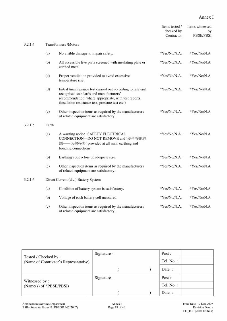
Annex I
Signature - Post :
Tel. No. :Tested / Checked by :(Name of Contractor’s Representative)
( ) Date :
Signature - Post :
Tel. No. :Witnessed by :(Name(s) of *PBSE/PBSI)
( ) Date :
Architectural Services Department Annex I Issue Date: 17 Dec 2007BSB– Standard Form No:PBS/SR.062(2007) Page 18 of 40 Revision Date: -
EE_TCP (2007 Edition)
Items tested /checked byContractor
Items witnessedby
PBSE/PBSI
3.2.1.4 Transformers /Motors
(a) No visible damage to impair safety. *Yes/No/N.A. *Yes/No/N.A.
(b) All accessible live parts screened with insulating plate orearthed metal.
*Yes/No/N.A. *Yes/No/N.A.
(c) Proper ventilation provided to avoid excessivetemperature rise.
*Yes/No/N.A. *Yes/No/N.A.
(d) Initial /maintenance test carried out according to relevantrecognised standards and manufacturers’recommendation, where appropriate, with test reports.(insulation resistance test, pressure test etc.)
*Yes/No/N.A. *Yes/No/N.A.
(e) Other inspection items as required by the manufacturersof related equipment are satisfactory.
*Yes/No/N.A. *Yes/No/N.A.
3.2.1.5 Earth
(a) A warning notice ‘SAFETY ELECTRICALCONNECTION—DO NOT REMOVE and ‘
—— ’ provided at all main earthing andbonding connections.
*Yes/No/N.A. *Yes/No/N.A.
(b) Earthing conductors of adequate size. *Yes/No/N.A. *Yes/No/N.A.
(c) Other inspection items as required by the manufacturersof related equipment are satisfactory.
*Yes/No/N.A. *Yes/No/N.A.
3.2.1.6 Direct Current (d.c.) Battery System
(a) Condition of battery system is satisfactory. *Yes/No/N.A. *Yes/No/N.A.
(b) Voltage of each battery cell measured. *Yes/No/N.A. *Yes/No/N.A.
(c) Other inspection items as required by the manufacturersof related equipment are satisfactory.
*Yes/No/N.A. *Yes/No/N.A.
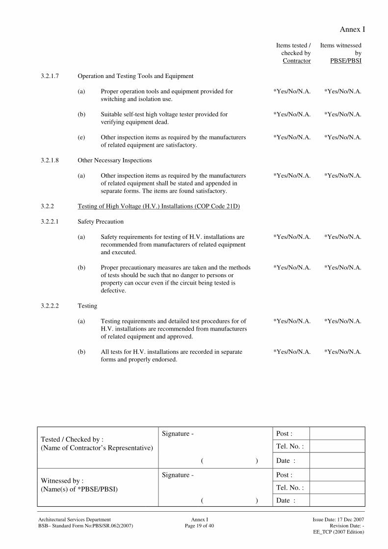
Annex I
Signature - Post :
Tel. No. :Tested / Checked by :(Name of Contractor’s Representative)
( ) Date :
Signature - Post :
Tel. No. :Witnessed by :(Name(s) of *PBSE/PBSI)
( ) Date :
Architectural Services Department Annex I Issue Date: 17 Dec 2007BSB– Standard Form No:PBS/SR.062(2007) Page 19 of 40 Revision Date: -
EE_TCP (2007 Edition)
Items tested /checked byContractor
Items witnessedby
PBSE/PBSI
3.2.1.7 Operation and Testing Tools and Equipment
(a) Proper operation tools and equipment provided forswitching and isolation use.
*Yes/No/N.A. *Yes/No/N.A.
(b) Suitable self-test high voltage tester provided forverifying equipment dead.
*Yes/No/N.A. *Yes/No/N.A.
(e) Other inspection items as required by the manufacturersof related equipment are satisfactory.
*Yes/No/N.A. *Yes/No/N.A.
3.2.1.8 Other Necessary Inspections
(a) Other inspection items as required by the manufacturersof related equipment shall be stated and appended inseparate forms. The items are found satisfactory.
*Yes/No/N.A. *Yes/No/N.A.
3.2.2 Testing of High Voltage (H.V.) Installations (COP Code 21D)
3.2.2.1 Safety Precaution
(a) Safety requirements for testing of H.V. installations arerecommended from manufacturers of related equipmentand executed.
*Yes/No/N.A. *Yes/No/N.A.
(b) Proper precautionary measures are taken and the methodsof tests should be such that no danger to persons orproperty can occur even if the circuit being tested isdefective.
*Yes/No/N.A. *Yes/No/N.A.
3.2.2.2 Testing
(a) Testing requirements and detailed test procedures for ofH.V. installations are recommended from manufacturersof related equipment and approved.
*Yes/No/N.A. *Yes/No/N.A.
(b) All tests for H.V. installations are recorded in separateforms and properly endorsed.
*Yes/No/N.A. *Yes/No/N.A.
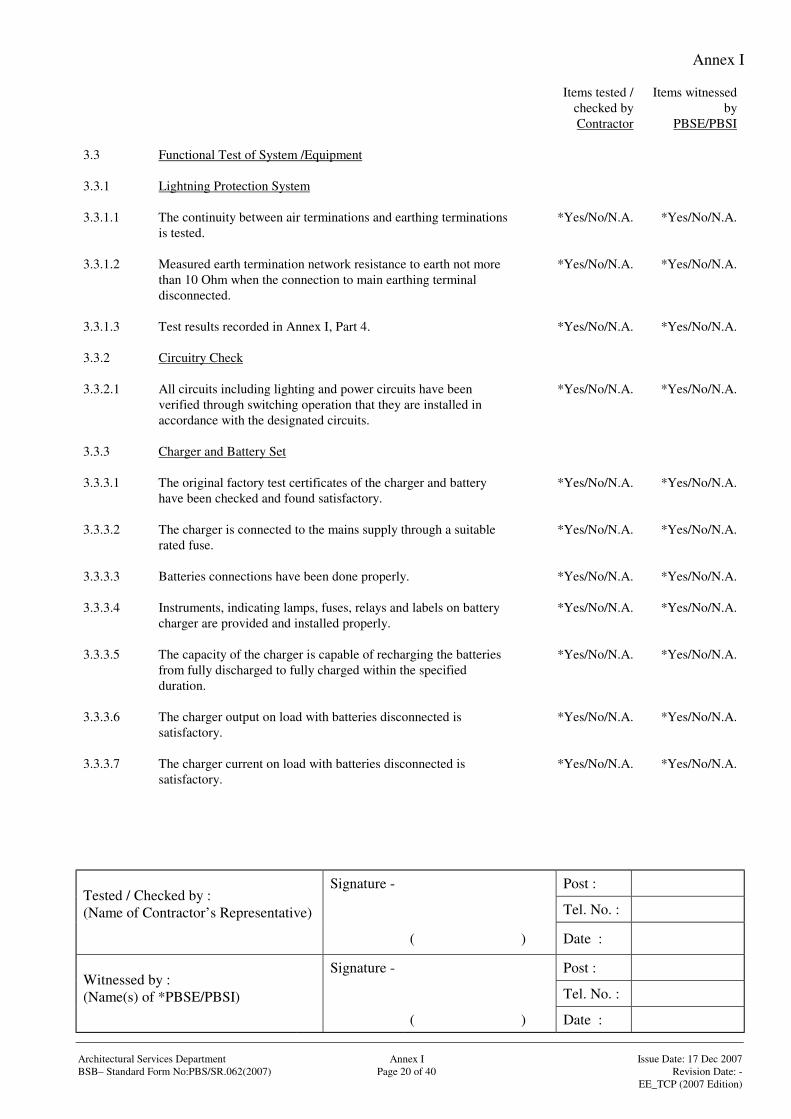
Annex I
Signature - Post :
Tel. No. :Tested / Checked by :(Name of Contractor’s Representative)
( ) Date :
Signature - Post :
Tel. No. :Witnessed by :(Name(s) of *PBSE/PBSI)
( ) Date :
Architectural Services Department Annex I Issue Date: 17 Dec 2007BSB– Standard Form No:PBS/SR.062(2007) Page 20 of 40 Revision Date: -
EE_TCP (2007 Edition)
Items tested /checked byContractor
Items witnessedby
PBSE/PBSI
3.3 Functional Test of System /Equipment
3.3.1 Lightning Protection System
3.3.1.1 The continuity between air terminations and earthing terminationsis tested.
*Yes/No/N.A. *Yes/No/N.A.
3.3.1.2 Measured earth termination network resistance to earth not morethan 10 Ohm when the connection to main earthing terminaldisconnected.
*Yes/No/N.A. *Yes/No/N.A.
3.3.1.3 Test results recorded in Annex I, Part 4. *Yes/No/N.A. *Yes/No/N.A.
3.3.2 Circuitry Check
3.3.2.1 All circuits including lighting and power circuits have beenverified through switching operation that they are installed inaccordance with the designated circuits.
*Yes/No/N.A. *Yes/No/N.A.
3.3.3 Charger and Battery Set
3.3.3.1 The original factory test certificates of the charger and batteryhave been checked and found satisfactory.
*Yes/No/N.A. *Yes/No/N.A.
3.3.3.2 The charger is connected to the mains supply through a suitablerated fuse.
*Yes/No/N.A. *Yes/No/N.A.
3.3.3.3 Batteries connections have been done properly. *Yes/No/N.A. *Yes/No/N.A.
3.3.3.4 Instruments, indicating lamps, fuses, relays and labels on batterycharger are provided and installed properly.
*Yes/No/N.A. *Yes/No/N.A.
3.3.3.5 The capacity of the charger is capable of recharging the batteriesfrom fully discharged to fully charged within the specifiedduration.
*Yes/No/N.A. *Yes/No/N.A.
3.3.3.6 The charger output on load with batteries disconnected issatisfactory.
*Yes/No/N.A. *Yes/No/N.A.
3.3.3.7 The charger current on load with batteries disconnected issatisfactory.
*Yes/No/N.A. *Yes/No/N.A.
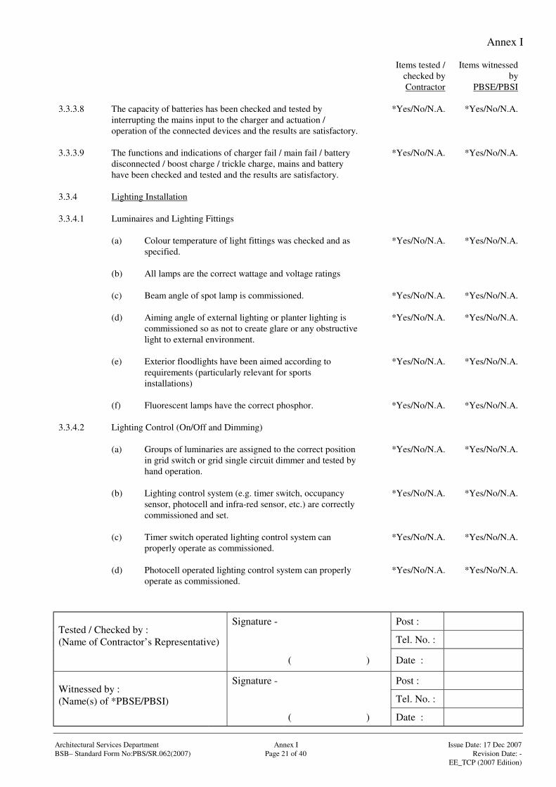
Annex I
Signature - Post :
Tel. No. :Tested / Checked by :(Name of Contractor’s Representative)
( ) Date :
Signature - Post :
Tel. No. :Witnessed by :(Name(s) of *PBSE/PBSI)
( ) Date :
Architectural Services Department Annex I Issue Date: 17 Dec 2007BSB– Standard Form No:PBS/SR.062(2007) Page 21 of 40 Revision Date: -
EE_TCP (2007 Edition)
Items tested /checked byContractor
Items witnessedby
PBSE/PBSI
3.3.3.8 The capacity of batteries has been checked and tested byinterrupting the mains input to the charger and actuation /operation of the connected devices and the results are satisfactory.
*Yes/No/N.A. *Yes/No/N.A.
3.3.3.9 The functions and indications of charger fail / main fail / batterydisconnected / boost charge / trickle charge, mains and batteryhave been checked and tested and the results are satisfactory.
*Yes/No/N.A. *Yes/No/N.A.
3.3.4 Lighting Installation
3.3.4.1 Luminaires and Lighting Fittings
(a) Colour temperature of light fittings was checked and asspecified.
*Yes/No/N.A. *Yes/No/N.A.
(b) All lamps are the correct wattage and voltage ratings
(c) Beam angle of spot lamp is commissioned. *Yes/No/N.A. *Yes/No/N.A.
(d) Aiming angle of external lighting or planter lighting iscommissioned so as not to create glare or any obstructivelight to external environment.
*Yes/No/N.A. *Yes/No/N.A.
(e) Exterior floodlights have been aimed according torequirements (particularly relevant for sportsinstallations)
*Yes/No/N.A. *Yes/No/N.A.
(f) Fluorescent lamps have the correct phosphor. *Yes/No/N.A. *Yes/No/N.A.
3.3.4.2 Lighting Control (On/Off and Dimming)
(a) Groups of luminaries are assigned to the correct positionin grid switch or grid single circuit dimmer and tested byhand operation.
*Yes/No/N.A. *Yes/No/N.A.
(b) Lighting control system (e.g. timer switch, occupancysensor, photocell and infra-red sensor, etc.) are correctlycommissioned and set.
*Yes/No/N.A. *Yes/No/N.A.
(c) Timer switch operated lighting control system canproperly operate as commissioned.
*Yes/No/N.A. *Yes/No/N.A.
(d) Photocell operated lighting control system can properlyoperate as commissioned.
*Yes/No/N.A. *Yes/No/N.A.
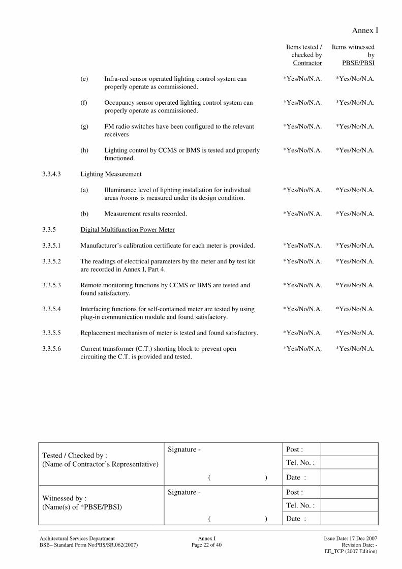
Annex I
Signature - Post :
Tel. No. :Tested / Checked by :(Name of Contractor’s Representative)
( ) Date :
Signature - Post :
Tel. No. :Witnessed by :(Name(s) of *PBSE/PBSI)
( ) Date :
Architectural Services Department Annex I Issue Date: 17 Dec 2007BSB– Standard Form No:PBS/SR.062(2007) Page 22 of 40 Revision Date: -
EE_TCP (2007 Edition)
Items tested /checked byContractor
Items witnessedby
PBSE/PBSI
(e) Infra-red sensor operated lighting control system canproperly operate as commissioned.
*Yes/No/N.A. *Yes/No/N.A.
(f) Occupancy sensor operated lighting control system canproperly operate as commissioned.
*Yes/No/N.A. *Yes/No/N.A.
(g) FM radio switches have been configured to the relevantreceivers
*Yes/No/N.A. *Yes/No/N.A.
(h) Lighting control by CCMS or BMS is tested and properlyfunctioned.
*Yes/No/N.A. *Yes/No/N.A.
3.3.4.3 Lighting Measurement
(a) Illuminance level of lighting installation for individualareas /rooms is measured under its design condition.
*Yes/No/N.A. *Yes/No/N.A.
(b) Measurement results recorded. *Yes/No/N.A. *Yes/No/N.A.
3.3.5 Digital Multifunction Power Meter
3.3.5.1 Manufacturer’s calibration certificate for each meter is provided. *Yes/No/N.A. *Yes/No/N.A.
3.3.5.2 The readings of electrical parameters by the meter and by test kitare recorded in Annex I, Part 4.
*Yes/No/N.A. *Yes/No/N.A.
3.3.5.3 Remote monitoring functions by CCMS or BMS are tested andfound satisfactory.
*Yes/No/N.A. *Yes/No/N.A.
3.3.5.4 Interfacing functions for self-contained meter are tested by usingplug-in communication module and found satisfactory.
*Yes/No/N.A. *Yes/No/N.A.
3.3.5.5 Replacement mechanism of meter is tested and found satisfactory. *Yes/No/N.A. *Yes/No/N.A.
3.3.5.6 Current transformer (C.T.) shorting block to prevent opencircuiting the C.T. is provided and tested.
*Yes/No/N.A. *Yes/No/N.A.
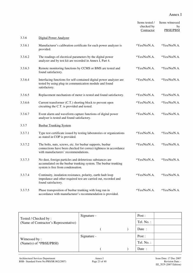
Annex I
Signature - Post :
Tel. No. :Tested / Checked by :(Name of Contractor’s Representative)
( ) Date :
Signature - Post :
Tel. No. :Witnessed by :(Name(s) of *PBSE/PBSI)
( ) Date :
Architectural Services Department Annex I Issue Date: 17 Dec 2007BSB– Standard Form No:PBS/SR.062(2007) Page 23 of 40 Revision Date: -
EE_TCP (2007 Edition)
Items tested /checked byContractor
Items witnessedby
PBSE/PBSI
3.3.6 Digital Power Analyzer
3.3.6.1 Manufacturer’s calibration certificate for each power analyzer isprovided.
*Yes/No/N.A. *Yes/No/N.A.
3.3.6.2 The readings of electrical parameters by the digital poweranalyzer and by test kit are recorded in Annex I, Part 4.
*Yes/No/N.A. *Yes/No/N.A.
3.3.6.3 Remote monitoring functions by CCMS or BMS are tested andfound satisfactory.
*Yes/No/N.A. *Yes/No/N.A.
3.3.6.4 Interfacing functions for self-contained digital power analyzer aretested by using plug-in communication module and foundsatisfactory.
*Yes/No/N.A. *Yes/No/N.A.
3.3.6.5 Replacement mechanism of meter is tested and found satisfactory. *Yes/No/N.A. *Yes/No/N.A.
3.3.6.6 Current transformer (C.T.) shorting block to prevent opencircuiting the C.T. is provided and tested.
*Yes/No/N.A. *Yes/No/N.A.
3.3.6.7 Event alarm and waveform capture functions of digital poweranalyser is tested and found satisfactory.
*Yes/No/N.A. *Yes/No/N.A.
3.3.7 Busbar Trunking System
3.3.7.1 Type test certificate issued by testing laboratories or organizationsas stated in COP is provided.
*Yes/No/N.A. *Yes/No/N.A.
3.3.7.2 The bolts, nuts, screws, etc. for busbar supports, busbarconnections have been checked for correct tightness in accordancewith manufacturers’ recommendations.
*Yes/No/N.A. *Yes/No/N.A.
3.3.7.3 No dust, foreign particles and deleterious substances areaccumulated on the busbar trunking system. The busbar trunkingsystem is free from condensation.
*Yes/No/N.A. *Yes/No/N.A.
3.3.7.4 Continuity, insulation resistance, polarity, earth fault loopimpedance and other required test are carried out, recorded andfound satisfactory.
*Yes/No/N.A. *Yes/No/N.A.
3.3.7.5 Phase transposition of busbar trunking with long run inaccordance with manufacturer’s recommendation is provided.
*Yes/No/N.A. *Yes/No/N.A.
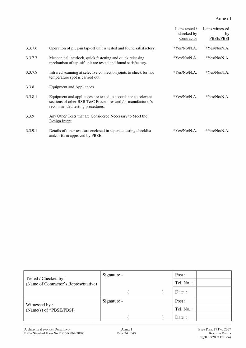
Annex I
Signature - Post :
Tel. No. :Tested / Checked by :(Name of Contractor’s Representative)
( ) Date :
Signature - Post :
Tel. No. :Witnessed by :(Name(s) of *PBSE/PBSI)
( ) Date :
Architectural Services Department Annex I Issue Date: 17 Dec 2007BSB– Standard Form No:PBS/SR.062(2007) Page 24 of 40 Revision Date: -
EE_TCP (2007 Edition)
Items tested /checked byContractor
Items witnessedby
PBSE/PBSI
3.3.7.6 Operation of plug-in tap-off unit is tested and found satisfactory. *Yes/No/N.A. *Yes/No/N.A.
3.3.7.7 Mechanical interlock, quick fastening and quick releasingmechanism of tap-off unit are tested and found satisfactory.
*Yes/No/N.A. *Yes/No/N.A.
3.3.7.8 Infrared scanning at selective connection joints to check for hottemperature spot is carried out.
*Yes/No/N.A. *Yes/No/N.A.
3.3.8 Equipment and Appliances
3.3.8.1 Equipment and appliances are tested in accordance to relevantsections of other BSB T&C Procedures and /or manufacturer’srecommended testing procedures.
*Yes/No/N.A. *Yes/No/N.A.
3.3.9 Any Other Tests that are Considered Necessary to Meet theDesign Intent
3.3.9.1 Details of other tests are enclosed in separate testing checklistand/or form approved by PBSE.
*Yes/No/N.A. *Yes/No/N.A.
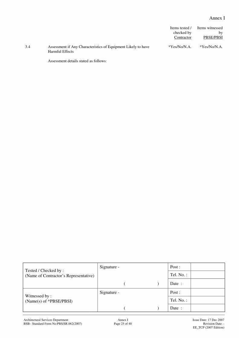
Annex I
Signature - Post :
Tel. No. :Tested / Checked by :(Name of Contractor’s Representative)
( ) Date :
Signature - Post :
Tel. No. :Witnessed by :(Name(s) of *PBSE/PBSI)
( ) Date :
Architectural Services Department Annex I Issue Date: 17 Dec 2007BSB– Standard Form No:PBS/SR.062(2007) Page 25 of 40 Revision Date: -
EE_TCP (2007 Edition)
Items tested /checked byContractor
Items witnessedby
PBSE/PBSI
3.4 Assessment if Any Characteristics of Equipment Likely to haveHarmful Effects
*Yes/No/N.A. *Yes/No/N.A.
Assessment details stated as follows:
Annex I
Signature - Post :
Tel. No. :Tested / Checked by :(Name of Contractor’s Representative)
( ) Date :
Signature - Post :
Tel. No. :Witnessed by :(Name(s) of *PBSE/PBSI)
( ) Date :
Architectural Services Department Annex I Issue Date: 17 Dec 2007BSB– Standard Form No:PBS/SR.062(2007) Page 26 of 40 Revision Date: -
EE_TCP (2007 Edition)
Items tested /checked byContractor
Items witnessedby
PBSE/PBSI
3.5 Comments *Yes/No/N.A. *Yes/No/N.A.
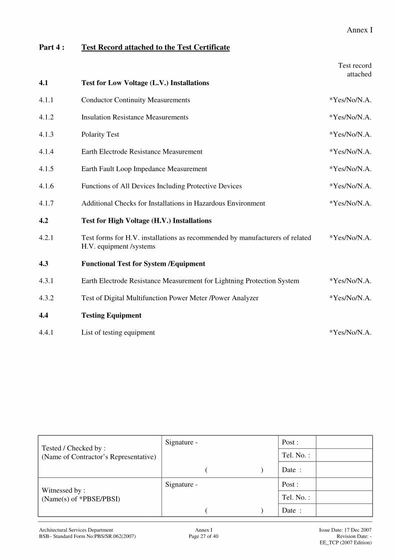
Annex I
Signature - Post :
Tel. No. :Tested / Checked by :(Name of Contractor’s Representative)
( ) Date :
Signature - Post :
Tel. No. :Witnessed by :(Name(s) of *PBSE/PBSI)
( ) Date :
Architectural Services Department Annex I Issue Date: 17 Dec 2007BSB– Standard Form No:PBS/SR.062(2007) Page 27 of 40 Revision Date: -
EE_TCP (2007 Edition)
Part 4 : Test Record attached to the Test Certificate
Test recordattached
4.1 Test for Low Voltage (L.V.) Installations
4.1.1 Conductor Continuity Measurements *Yes/No/N.A.
4.1.2 Insulation Resistance Measurements *Yes/No/N.A.
4.1.3 Polarity Test *Yes/No/N.A.
4.1.4 Earth Electrode Resistance Measurement *Yes/No/N.A.
4.1.5 Earth Fault Loop Impedance Measurement *Yes/No/N.A.
4.1.6 Functions of All Devices Including Protective Devices *Yes/No/N.A.
4.1.7 Additional Checks for Installations in Hazardous Environment *Yes/No/N.A.
4.2 Test for High Voltage (H.V.) Installations
4.2.1 Test forms for H.V. installations as recommended by manufacturers of relatedH.V. equipment /systems
*Yes/No/N.A.
4.3 Functional Test for System /Equipment
4.3.1 Earth Electrode Resistance Measurement for Lightning Protection System *Yes/No/N.A.
4.3.2 Test of Digital Multifunction Power Meter /Power Analyzer *Yes/No/N.A.
4.4 Testing Equipment
4.4.1 List of testing equipment *Yes/No/N.A.
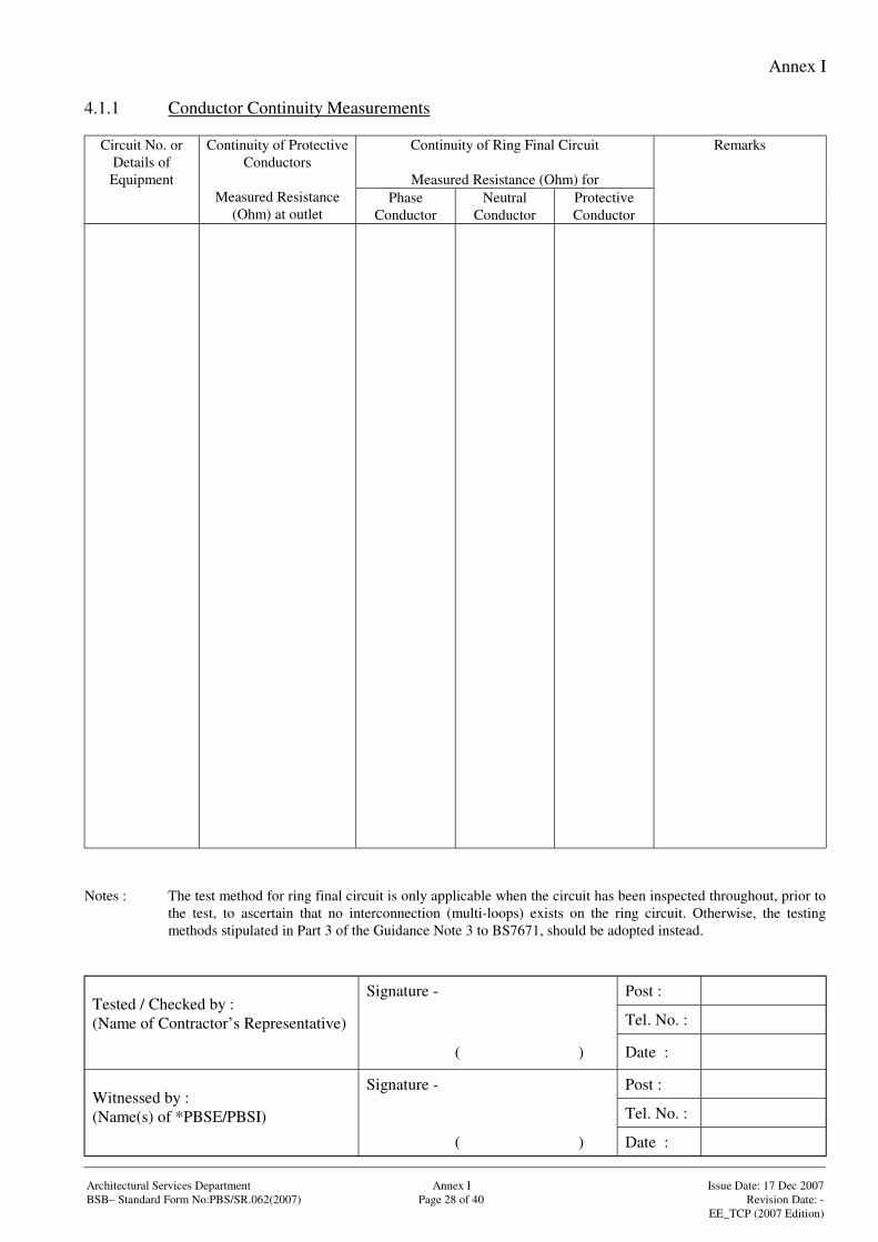
Annex I
Signature - Post :
Tel. No. :Tested / Checked by :(Name of Contractor’s Representative)
( ) Date :
Signature - Post :
Tel. No. :Witnessed by :(Name(s) of *PBSE/PBSI)
( ) Date :
Architectural Services Department Annex I Issue Date: 17 Dec 2007BSB– Standard Form No:PBS/SR.062(2007) Page 28 of 40 Revision Date: -
EE_TCP (2007 Edition)
4.1.1 Conductor Continuity Measurements
Continuity of Ring Final Circuit
Measured Resistance (Ohm) for
Circuit No. orDetails ofEquipment
Continuity of ProtectiveConductors
Measured Resistance(Ohm) at outlet
PhaseConductor
NeutralConductor
ProtectiveConductor
Remarks
Notes : The test method for ring final circuit is only applicable when the circuit has been inspected throughout, prior tothe test, to ascertain that no interconnection (multi-loops) exists on the ring circuit. Otherwise, the testingmethods stipulated in Part 3 of the Guidance Note 3 to BS7671, should be adopted instead.
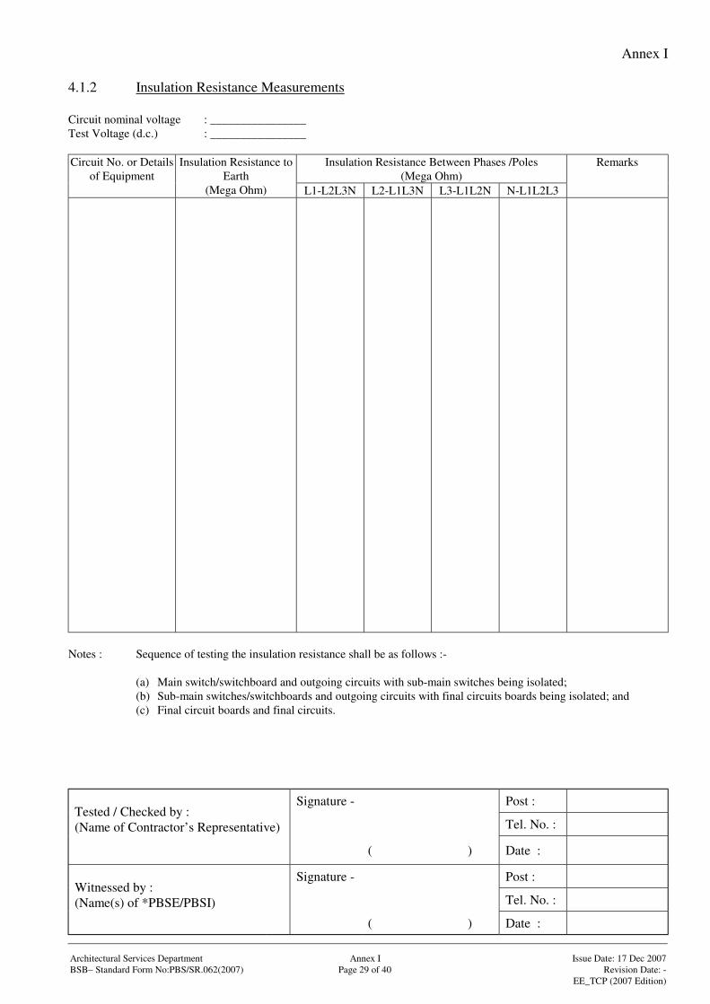
Annex I
Signature - Post :
Tel. No. :Tested / Checked by :(Name of Contractor’s Representative)
( ) Date :
Signature - Post :
Tel. No. :Witnessed by :(Name(s) of *PBSE/PBSI)
( ) Date :
Architectural Services Department Annex I Issue Date: 17 Dec 2007BSB– Standard Form No:PBS/SR.062(2007) Page 29 of 40 Revision Date: -
EE_TCP (2007 Edition)
4.1.2 Insulation Resistance Measurements
Circuit nominal voltage : ________________Test Voltage (d.c.) : ________________
Insulation Resistance Between Phases /Poles(Mega Ohm)
Circuit No. or Detailsof Equipment
Insulation Resistance toEarth
(Mega Ohm) L1-L2L3N L2-L1L3N L3-L1L2N N-L1L2L3
Remarks
Notes : Sequence of testing the insulation resistance shall be as follows :-
(a) Main switch/switchboard and outgoing circuits with sub-main switches being isolated;(b) Sub-main switches/switchboards and outgoing circuits with final circuits boards being isolated; and(c) Final circuit boards and final circuits.
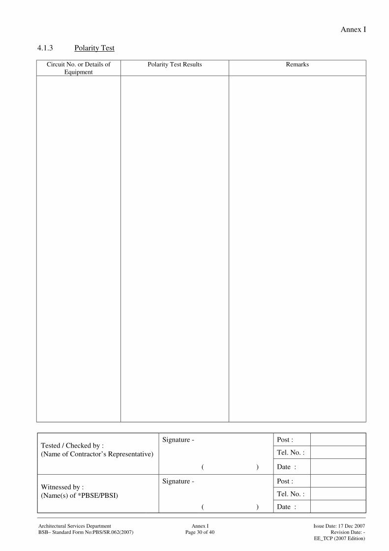
Annex I
Signature - Post :
Tel. No. :Tested / Checked by :(Name of Contractor’s Representative)
( ) Date :
Signature - Post :
Tel. No. :Witnessed by :(Name(s) of *PBSE/PBSI)
( ) Date :
Architectural Services Department Annex I Issue Date: 17 Dec 2007BSB– Standard Form No:PBS/SR.062(2007) Page 30 of 40 Revision Date: -
EE_TCP (2007 Edition)
4.1.3 Polarity Test
Circuit No. or Details ofEquipment
Polarity Test Results Remarks
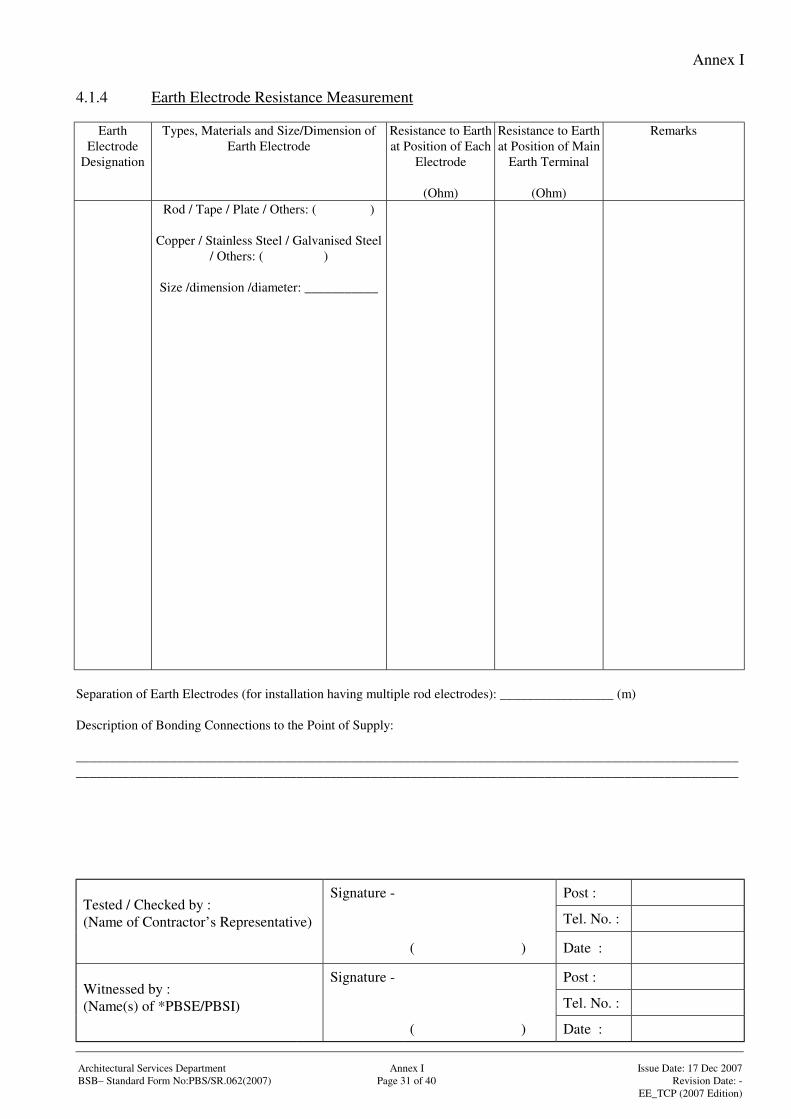
Annex I
Signature - Post :
Tel. No. :Tested / Checked by :(Name of Contractor’s Representative)
( ) Date :
Signature - Post :
Tel. No. :Witnessed by :(Name(s) of *PBSE/PBSI)
( ) Date :
Architectural Services Department Annex I Issue Date: 17 Dec 2007BSB– Standard Form No:PBS/SR.062(2007) Page 31 of 40 Revision Date: -
EE_TCP (2007 Edition)
4.1.4 Earth Electrode Resistance Measurement
EarthElectrode
Designation
Types, Materials and Size/Dimension ofEarth Electrode
Resistance to Earthat Position of Each
Electrode
(Ohm)
Resistance to Earthat Position of Main
Earth Terminal
(Ohm)
Remarks
Rod / Tape / Plate / Others: ( )
Copper / Stainless Steel / Galvanised Steel/ Others: ( )
Size /dimension /diameter: ___________
Separation of Earth Electrodes (for installation having multiple rod electrodes): _________________ (m)
Description of Bonding Connections to the Point of Supply:
______________________________________________________________________________________________________________________________________________________________________________________________________
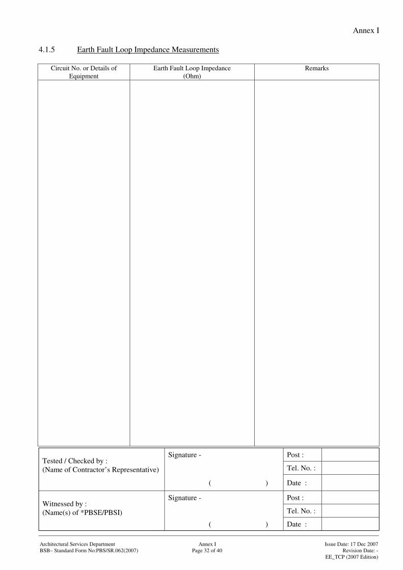
Annex I
Signature - Post :
Tel. No. :Tested / Checked by :(Name of Contractor’s Representative)
( ) Date :
Signature - Post :
Tel. No. :Witnessed by :(Name(s) of *PBSE/PBSI)
( ) Date :
Architectural Services Department Annex I Issue Date: 17 Dec 2007BSB– Standard Form No:PBS/SR.062(2007) Page 32 of 40 Revision Date: -
EE_TCP (2007 Edition)
4.1.5 Earth Fault Loop Impedance Measurements
Circuit No. or Details ofEquipment
Earth Fault Loop Impedance(Ohm)
Remarks
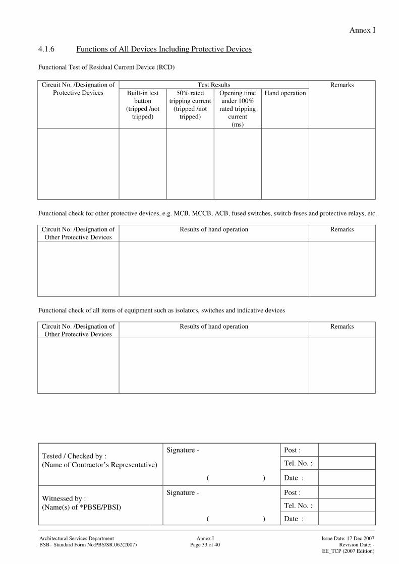
Annex I
Signature - Post :
Tel. No. :Tested / Checked by :(Name of Contractor’s Representative)
( ) Date :
Signature - Post :
Tel. No. :Witnessed by :(Name(s) of *PBSE/PBSI)
( ) Date :
Architectural Services Department Annex I Issue Date: 17 Dec 2007BSB– Standard Form No:PBS/SR.062(2007) Page 33 of 40 Revision Date: -
EE_TCP (2007 Edition)
4.1.6 Functions of All Devices Including Protective Devices
Functional Test of Residual Current Device (RCD)
Test ResultsCircuit No. /Designation ofProtective Devices Built-in test
button(tripped /not
tripped)
50% ratedtripping current
(tripped /nottripped)
Opening timeunder 100%
rated trippingcurrent
(ms)
Hand operationRemarks
Functional check for other protective devices, e.g. MCB, MCCB, ACB, fused switches, switch-fuses and protective relays, etc.
Circuit No. /Designation ofOther Protective Devices
Results of hand operation Remarks
Functional check of all items of equipment such as isolators, switches and indicative devices
Circuit No. /Designation ofOther Protective Devices
Results of hand operation Remarks
Annex I
Signature - Post :
Tel. No. :Tested / Checked by :(Name of Contractor’s Representative)
( ) Date :
Signature - Post :
Tel. No. :Witnessed by :(Name(s) of *PBSE/PBSI)
( ) Date :
Architectural Services Department Annex I Issue Date: 17 Dec 2007BSB– Standard Form No:PBS/SR.062(2007) Page 34 of 40 Revision Date: -
EE_TCP (2007 Edition)
4.1.7 Additional Checks for Installations in Hazardous Environment
Notes: Details of additional checks for installations in hazardous environment shall be recorded in this form whereasappropriate.
Annex I
Signature - Post :
Tel. No. :Tested / Checked by :(Name of Contractor’s Representative)
( ) Date :
Signature - Post :
Tel. No. :Witnessed by :(Name(s) of *PBSE/PBSI)
( ) Date :
Architectural Services Department Annex I Issue Date: 17 Dec 2007BSB– Standard Form No:PBS/SR.062(2007) Page 35 of 40 Revision Date: -
EE_TCP (2007 Edition)
4.2 Test for High Voltage (H.V.) Installations
Notes: Details of test requirements as recommended by manufacturers of relative H.V. equipment /systems shall bestated and appended here. Test results of respective requirements shall also be recorded and appended in thisform whereas appropriate.
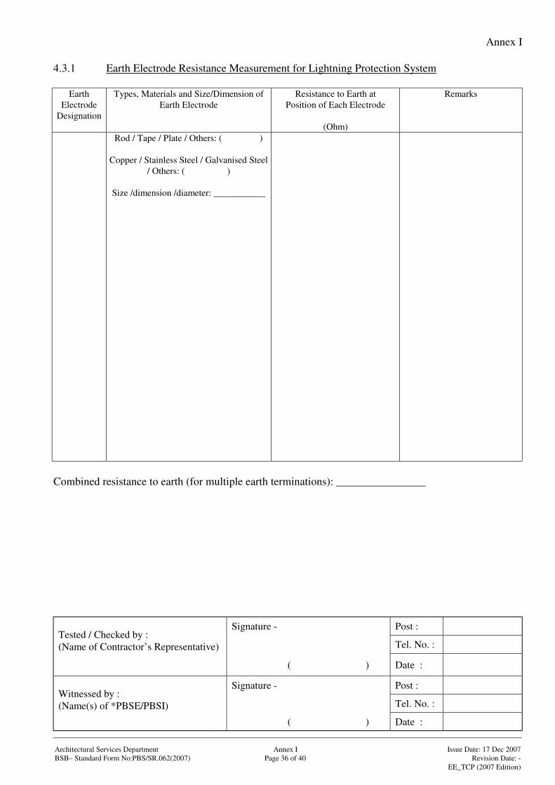
Annex I
Signature - Post :
Tel. No. :Tested / Checked by :(Name of Contractor’s Representative)
( ) Date :
Signature - Post :
Tel. No. :Witnessed by :(Name(s) of *PBSE/PBSI)
( ) Date :
Architectural Services Department Annex I Issue Date: 17 Dec 2007BSB– Standard Form No:PBS/SR.062(2007) Page 36 of 40 Revision Date: -
EE_TCP (2007 Edition)
4.3.1 Earth Electrode Resistance Measurement for Lightning Protection System
EarthElectrode
Designation
Types, Materials and Size/Dimension ofEarth Electrode
Resistance to Earth atPosition of Each Electrode
(Ohm)
Remarks
Rod / Tape / Plate / Others: ( )
Copper / Stainless Steel / Galvanised Steel/ Others: ( )
Size /dimension /diameter: ___________
Combined resistance to earth (for multiple earth terminations): ________________
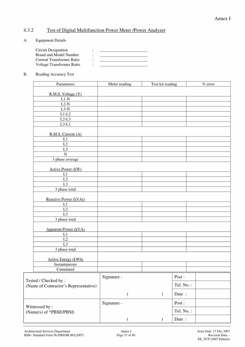
Annex I
Signature - Post :
Tel. No. :Tested / Checked by :(Name of Contractor’s Representative)
( ) Date :
Signature - Post :
Tel. No. :Witnessed by :(Name(s) of *PBSE/PBSI)
( ) Date :
Architectural Services Department Annex I Issue Date: 17 Dec 2007BSB– Standard Form No:PBS/SR.062(2007) Page 37 of 40 Revision Date: -
EE_TCP (2007 Edition)
4.3.2 Test of Digital Multifunction Power Meter /Power Analyzer
A. Equipment Details
Circuit Designation : _______________________Brand and Model Number : _______________________Current Transformer Ratio : _______________________Voltage Transformer Ratio : _______________________
B. Reading Accuracy Test
Parameters Meter reading Test kit reading % error
R.M.S. Voltage (V)L1-NL2-NL3-NL1-L2L2-L3L3-L1
R.M.S. Current (A)L1L2L3N
3 phase average
Active Power (kW)L1L2L3
3 phase total
Reactive Power (kVAr)L1L2L3
3 phase total
Apparent Power (kVA)L1L2L3
3 phase total
Active Energy (kWh)Instantaneous
Cumulated
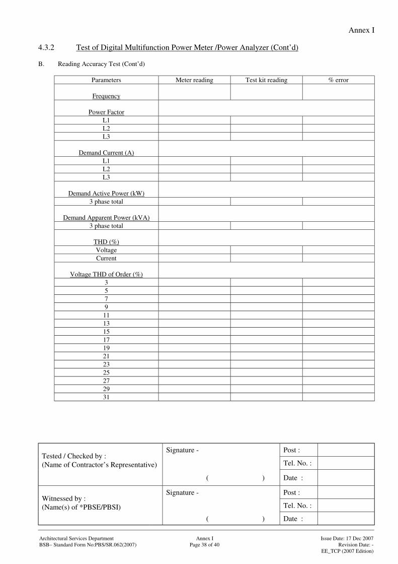
Annex I
Signature - Post :
Tel. No. :Tested / Checked by :(Name of Contractor’s Representative)
( ) Date :
Signature - Post :
Tel. No. :Witnessed by :(Name(s) of *PBSE/PBSI)
( ) Date :
Architectural Services Department Annex I Issue Date: 17 Dec 2007BSB– Standard Form No:PBS/SR.062(2007) Page 38 of 40 Revision Date: -
EE_TCP (2007 Edition)
4.3.2 Test of Digital Multifunction Power Meter /Power Analyzer (Cont’d)
B. Reading Accuracy Test (Cont’d)
Parameters Meter reading Test kit reading % error
Frequency
Power FactorL1L2L3
Demand Current (A)L1L2L3
Demand Active Power (kW)3 phase total
Demand Apparent Power (kVA)3 phase total
THD (%)VoltageCurrent
Voltage THD of Order (%)3579
1113151719212325272931
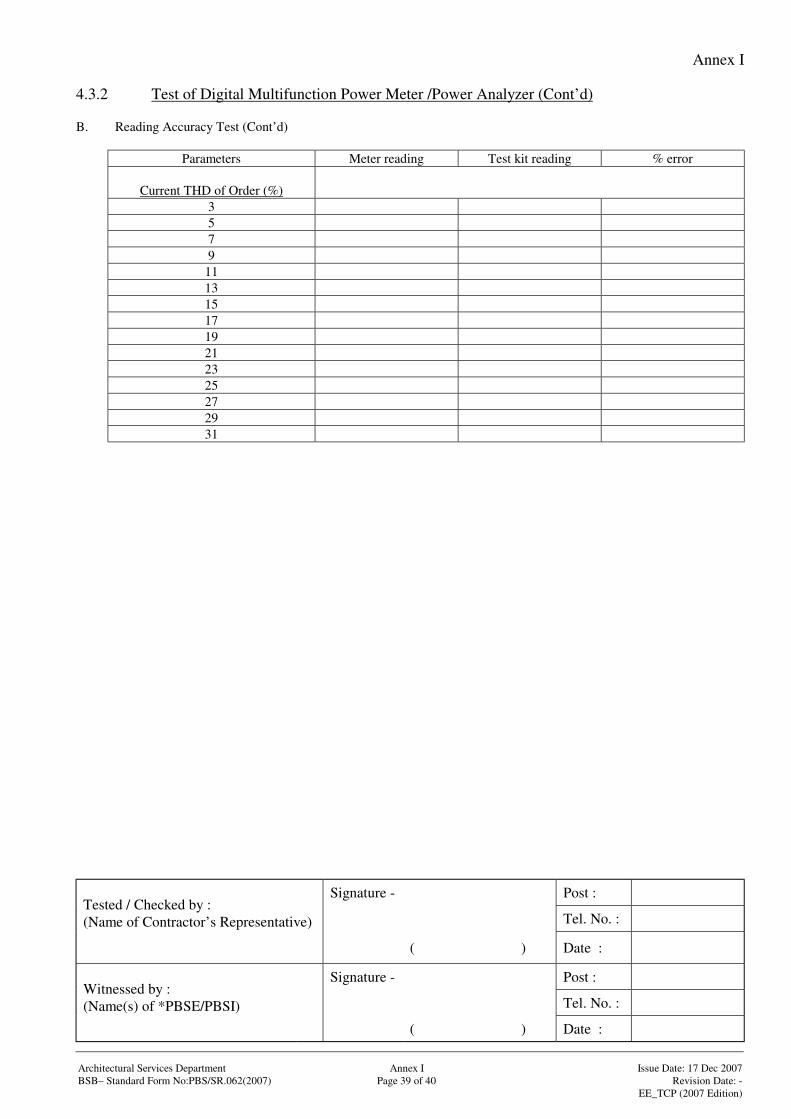
Annex I
Signature - Post :
Tel. No. :Tested / Checked by :(Name of Contractor’s Representative)
( ) Date :
Signature - Post :
Tel. No. :Witnessed by :(Name(s) of *PBSE/PBSI)
( ) Date :
Architectural Services Department Annex I Issue Date: 17 Dec 2007BSB– Standard Form No:PBS/SR.062(2007) Page 39 of 40 Revision Date: -
EE_TCP (2007 Edition)
4.3.2 Test of Digital Multifunction Power Meter /Power Analyzer (Cont’d)
B. Reading Accuracy Test (Cont’d)
Parameters Meter reading Test kit reading % error
Current THD of Order (%)3579
1113151719212325272931
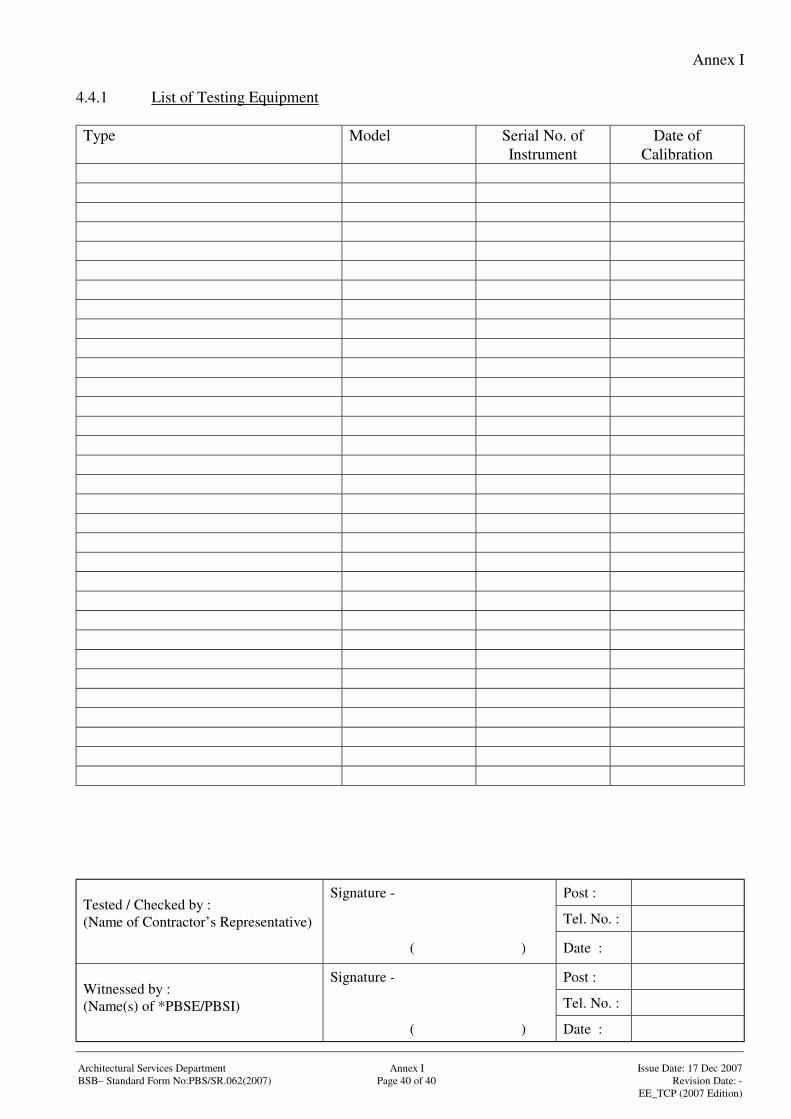
Annex I
Signature - Post :
Tel. No. :Tested / Checked by :(Name of Contractor’s Representative)
( ) Date :
Signature - Post :
Tel. No. :Witnessed by :(Name(s) of *PBSE/PBSI)
( ) Date :
Architectural Services Department Annex I Issue Date: 17 Dec 2007BSB– Standard Form No:PBS/SR.062(2007) Page 40 of 40 Revision Date: -
EE_TCP (2007 Edition)
4.4.1 List of Testing Equipment
Type Model Serial No. ofInstrument
Date ofCalibration
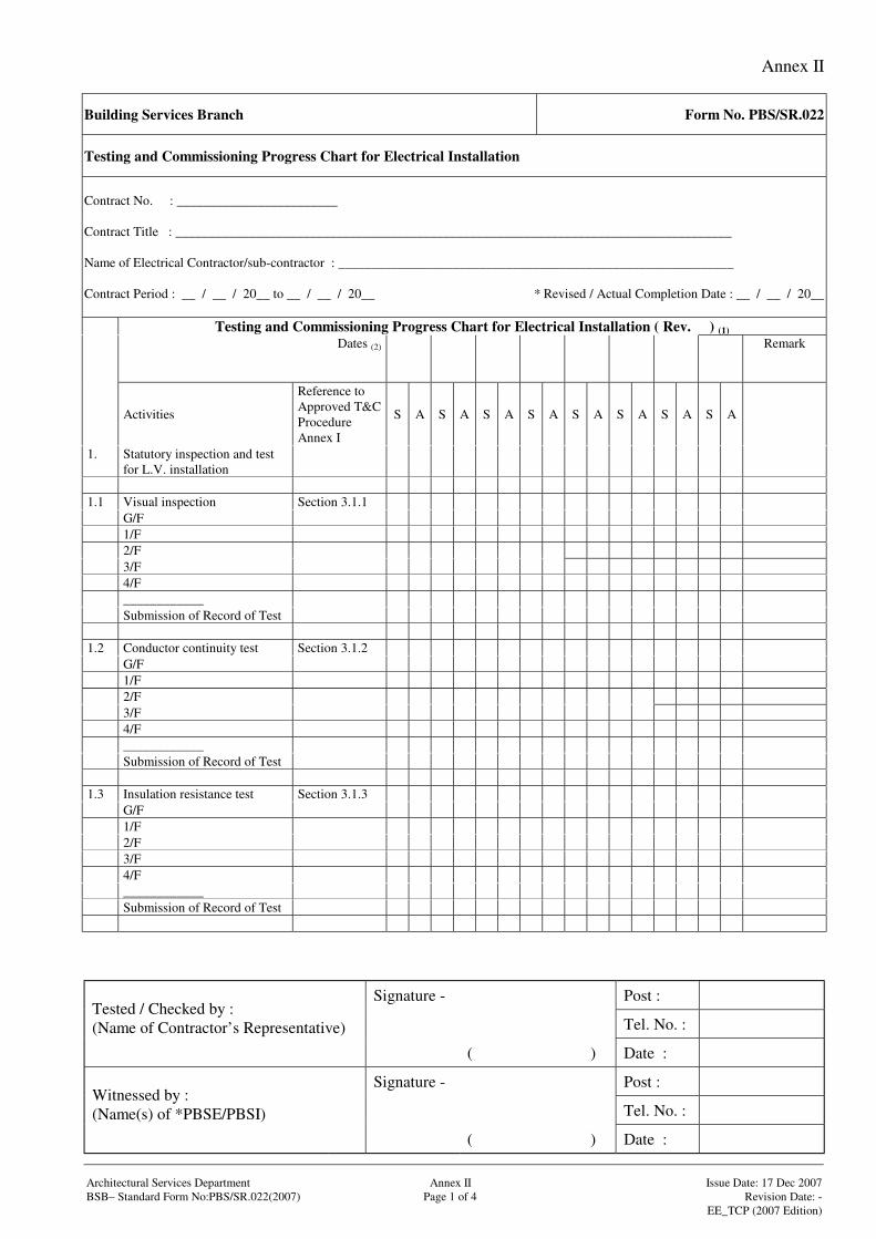
Annex II
Signature - Post :
Tel. No. :Tested / Checked by :(Name of Contractor’s Representative)
( ) Date :
Signature - Post :
Tel. No. :Witnessed by :(Name(s) of *PBSE/PBSI)
( ) Date :
Architectural Services Department Annex II Issue Date: 17 Dec 2007BSB– Standard Form No:PBS/SR.022(2007) Page 1 of 4 Revision Date: -
EE_TCP (2007 Edition)
Building Services Branch Form No. PBS/SR.022
Testing and Commissioning Progress Chart for Electrical Installation
Contract No. : ________________________
Contract Title : ___________________________________________________________________________________
Name of Electrical Contractor/sub-contractor : ___________________________________________________________
Contract Period : __ / __ / 20__ to __ / __ / 20__ * Revised / Actual Completion Date : __ / __ / 20__
Testing and Commissioning Progress Chart for Electrical Installation ( Rev. ) (1)
Dates (2) Remark
Activities
Reference toApproved T&CProcedureAnnex I
S A S A S A S A S A S A S A S A
1. Statutory inspection and testfor L.V. installation
1.1 Visual inspection Section 3.1.1G/F1/F2/F3/F4/F____________Submission of Record of Test
1.2 Conductor continuity test Section 3.1.2G/F1/F2/F3/F4/F____________Submission of Record of Test
1.3 Insulation resistance test Section 3.1.3G/F1/F2/F3/F4/F____________Submission of Record of Test
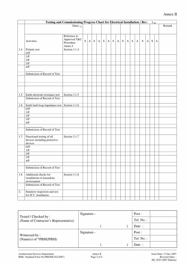
Annex II
Signature - Post :
Tel. No. :Tested / Checked by :(Name of Contractor’s Representative)
( ) Date :
Signature - Post :
Tel. No. :Witnessed by :(Name(s) of *PBSE/PBSI)
( ) Date :
Architectural Services Department Annex II Issue Date: 17 Dec 2007BSB– Standard Form No:PBS/SR.022(2007) Page 2 of 4 Revision Date: -
EE_TCP (2007 Edition)
Testing and Commissioning Progress Chart for Electrical Installation ( Rev. ) (1)
Dates (2) Remark
Activities
Reference toApproved T&CProcedureAnnex I
S A S A S A S A S A S A S A S A
1.4 Polarity test Section 3.1.4G/F1/F2/F3/F4/F____________Submission of Record of Test
1.5 Earth electrode resistance test Section 3.1.5Submission of Record of Test
1.6 Earth fault loop impedance test Section 3.1.6G/F1/F2/F3/F4/F____________Submission of Record of Test
1.7 Functional testing of alldevices including protectivedevices
Section 3.1.7
G/F1/F2/F3/F4/F____________Submission of Record of Test
1.8 Additional checks forinstallations in hazardousenvironment
Section 3.1.8
Submission of Record of Test
2. Statutory inspection and testfor H.V. installation
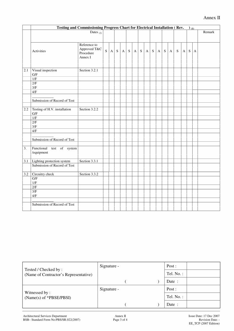
Annex II
Signature - Post :
Tel. No. :Tested / Checked by :(Name of Contractor’s Representative)
( ) Date :
Signature - Post :
Tel. No. :Witnessed by :(Name(s) of *PBSE/PBSI)
( ) Date :
Architectural Services Department Annex II Issue Date: 17 Dec 2007BSB– Standard Form No:PBS/SR.022(2007) Page 3 of 4 Revision Date: -
EE_TCP (2007 Edition)
Testing and Commissioning Progress Chart for Electrical Installation ( Rev. ) (1)
Dates (2) Remark
Activities
Reference toApproved T&CProcedureAnnex I
S A S A S A S A S A S A S A S A
2.1 Visual inspection Section 3.2.1G/F1/F2/F3/F4/F____________Submission of Record of Test
2.2 Testing of H.V. installation Section 3.2.2G/F1/F2/F3/F4/F____________Submission of Record of Test
3. Functional test of system/equipment
3.1 Lighting protection system Section 3.3.1Submission of Record of Test
3.2 Circuitry check Section 3.3.2G/F1/F2/F3/F4/F____________Submission of Record of Test
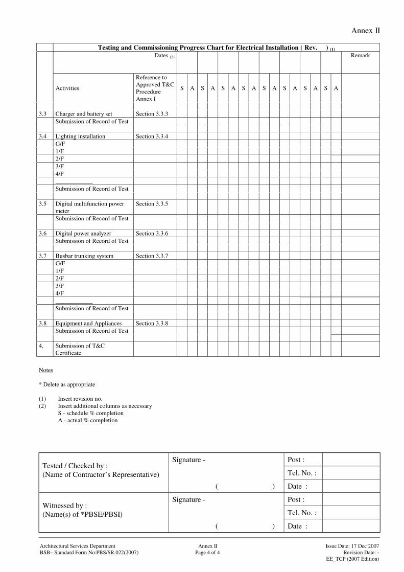
Annex II
Signature - Post :
Tel. No. :Tested / Checked by :(Name of Contractor’s Representative)
( ) Date :
Signature - Post :
Tel. No. :Witnessed by :(Name(s) of *PBSE/PBSI)
( ) Date :
Architectural Services Department Annex II Issue Date: 17 Dec 2007BSB– Standard Form No:PBS/SR.022(2007) Page 4 of 4 Revision Date: -
EE_TCP (2007 Edition)
Testing and Commissioning Progress Chart for Electrical Installation ( Rev. ) (1)
Dates (2) Remark
Activities
Reference toApproved T&CProcedureAnnex I
S A S A S A S A S A S A S A S A
3.3 Charger and battery set Section 3.3.3Submission of Record of Test
3.4 Lighting installation Section 3.3.4G/F1/F2/F3/F4/F____________Submission of Record of Test
3.5 Digital multifunction powermeter
Section 3.3.5
Submission of Record of Test
3.6 Digital power analyzer Section 3.3.6Submission of Record of Test
3.7 Busbar trunking system Section 3.3.7G/F1/F2/F3/F4/F____________Submission of Record of Test
3.8 Equipment and Appliances Section 3.3.8Submission of Record of Test
4. Submission of T&CCertificate
Notes
* Delete as appropriate
(1) Insert revision no.(2) Insert additional columns as necessary
S - schedule % completionA - actual % completion
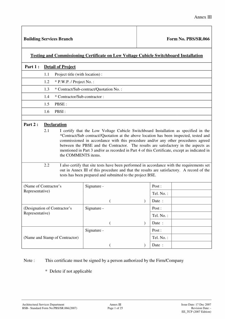
Annex III
Architectural Services Department Annex III Issue Date: 17 Dec 2007BSB– Standard Form No:PBS/SR.066(2007) Page 1 of 25 Revision Date: -
EE_TCP (2007 Edition)
Building Services Branch Form No. PBS/SR.066
Testing and Commissioning Certificate on Low Voltage Cubicle Switchboard Installation
Part 1 : Detail of Project
1.1 Project title (with location) :
1.2 * P.W.P. / Project No. :
1.3 * Contract/Sub-contract/Quotation No. :
1.4 * Contractor/Sub-contractor :
1.5 PBSE :
1.6 PBSI :
Part 2 : Declaration2.1 I certify that the Low Voltage Cubicle Switchboard Installation as specified in the
*Contract/Sub contract//Quotation at the above location has been inspected, tested andcommissioned in accordance with this procedure and/or any other procedures agreedbetween the PBSE and the Contractor. The results are satisfactory in the aspects asmentioned in Part 3 and/or as recorded in Part 4 of this Certificate, except as indicated inthe COMMENTS items.
2.2 I also certify that site tests have been performed in accordance with the requirements setout in Annex III of this procedure and that the results are satisfactory. A record of thetests has been prepared and submitted to the project BSE.
Signature - Post :
Tel. No. :
(Name of Contractor’sRepresentative)
( ) Date :
Signature - Post :
Tel. No. :
(Designation of Contractor’sRepresentative)
( ) Date :
Signature - Post :
Tel. No. :(Name and Stamp of Contractor)
( ) Date :
Note : This certificate must be signed by a person authorized by the Firm/Company
* Delete if not applicable
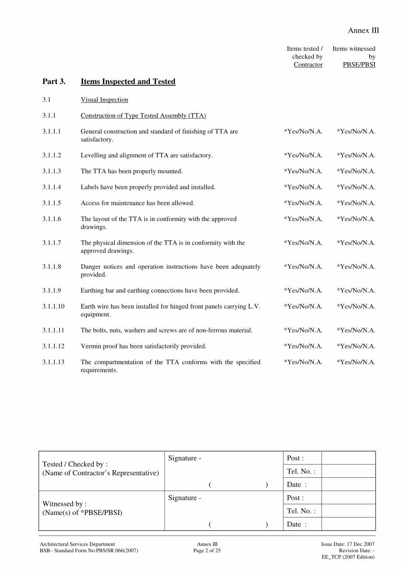
Annex III
Signature - Post :
Tel. No. :Tested / Checked by :(Name of Contractor’s Representative)
( ) Date :
Signature - Post :
Tel. No. :Witnessed by :(Name(s) of *PBSE/PBSI)
( ) Date :
Architectural Services Department Annex III Issue Date: 17 Dec 2007BSB– Standard Form No:PBS/SR.066(2007) Page 2 of 25 Revision Date: -
EE_TCP (2007 Edition)
Items tested /checked byContractor
Items witnessedby
PBSE/PBSI
Part 3. Items Inspected and Tested
3.1 Visual Inspection
3.1.1 Construction of Type Tested Assembly (TTA)
3.1.1.1 General construction and standard of finishing of TTA aresatisfactory.
*Yes/No/N.A. *Yes/No/N.A.
3.1.1.2 Levelling and alignment of TTA are satisfactory. *Yes/No/N.A. *Yes/No/N.A.
3.1.1.3 The TTA has been properly mounted. *Yes/No/N.A. *Yes/No/N.A.
3.1.1.4 Labels have been properly provided and installed. *Yes/No/N.A. *Yes/No/N.A.
3.1.1.5 Access for maintenance has been allowed. *Yes/No/N.A. *Yes/No/N.A.
3.1.1.6 The layout of the TTA is in conformity with the approveddrawings.
*Yes/No/N.A. *Yes/No/N.A.
3.1.1.7 The physical dimension of the TTA is in conformity with theapproved drawings.
*Yes/No/N.A. *Yes/No/N.A.
3.1.1.8 Danger notices and operation instructions have been adequatelyprovided.
*Yes/No/N.A. *Yes/No/N.A.
3.1.1.9 Earthing bar and earthing connections have been provided. *Yes/No/N.A. *Yes/No/N.A.
3.1.1.10 Earth wire has been installed for hinged front panels carrying L.V.equipment.
*Yes/No/N.A. *Yes/No/N.A.
3.1.1.11 The bolts, nuts, washers and screws are of non-ferrous material. *Yes/No/N.A. *Yes/No/N.A.
3.1.1.12 Vermin proof has been satisfactorily provided. *Yes/No/N.A. *Yes/No/N.A.
3.1.1.13 The compartmentation of the TTA conforms with the specifiedrequirements.
*Yes/No/N.A. *Yes/No/N.A.
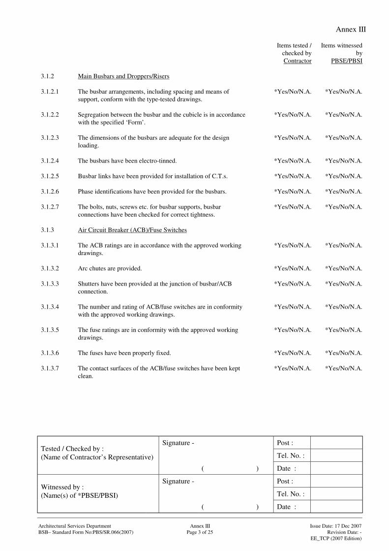
Annex III
Signature - Post :
Tel. No. :Tested / Checked by :(Name of Contractor’s Representative)
( ) Date :
Signature - Post :
Tel. No. :Witnessed by :(Name(s) of *PBSE/PBSI)
( ) Date :
Architectural Services Department Annex III Issue Date: 17 Dec 2007BSB– Standard Form No:PBS/SR.066(2007) Page 3 of 25 Revision Date: -
EE_TCP (2007 Edition)
Items tested /checked byContractor
Items witnessedby
PBSE/PBSI
3.1.2 Main Busbars and Droppers/Risers
3.1.2.1 The busbar arrangements, including spacing and means ofsupport, conform with the type-tested drawings.
*Yes/No/N.A. *Yes/No/N.A.
3.1.2.2 Segregation between the busbar and the cubicle is in accordancewith the specified ‘Form’.
*Yes/No/N.A. *Yes/No/N.A.
3.1.2.3 The dimensions of the busbars are adequate for the designloading.
*Yes/No/N.A. *Yes/No/N.A.
3.1.2.4 The busbars have been electro-tinned. *Yes/No/N.A. *Yes/No/N.A.
3.1.2.5 Busbar links have been provided for installation of C.T.s. *Yes/No/N.A. *Yes/No/N.A.
3.1.2.6 Phase identifications have been provided for the busbars. *Yes/No/N.A. *Yes/No/N.A.
3.1.2.7 The bolts, nuts, screws etc. for busbar supports, busbarconnections have been checked for correct tightness.
*Yes/No/N.A. *Yes/No/N.A.
3.1.3 Air Circuit Breaker (ACB)/Fuse Switches
3.1.3.1 The ACB ratings are in accordance with the approved workingdrawings.
*Yes/No/N.A. *Yes/No/N.A.
3.1.3.2 Arc chutes are provided. *Yes/No/N.A. *Yes/No/N.A.
3.1.3.3 Shutters have been provided at the junction of busbar/ACBconnection.
*Yes/No/N.A. *Yes/No/N.A.
3.1.3.4 The number and rating of ACB/fuse switches are in conformitywith the approved working drawings.
*Yes/No/N.A. *Yes/No/N.A.
3.1.3.5 The fuse ratings are in conformity with the approved workingdrawings.
*Yes/No/N.A. *Yes/No/N.A.
3.1.3.6 The fuses have been properly fixed. *Yes/No/N.A. *Yes/No/N.A.
3.1.3.7 The contact surfaces of the ACB/fuse switches have been keptclean.
*Yes/No/N.A. *Yes/No/N.A.
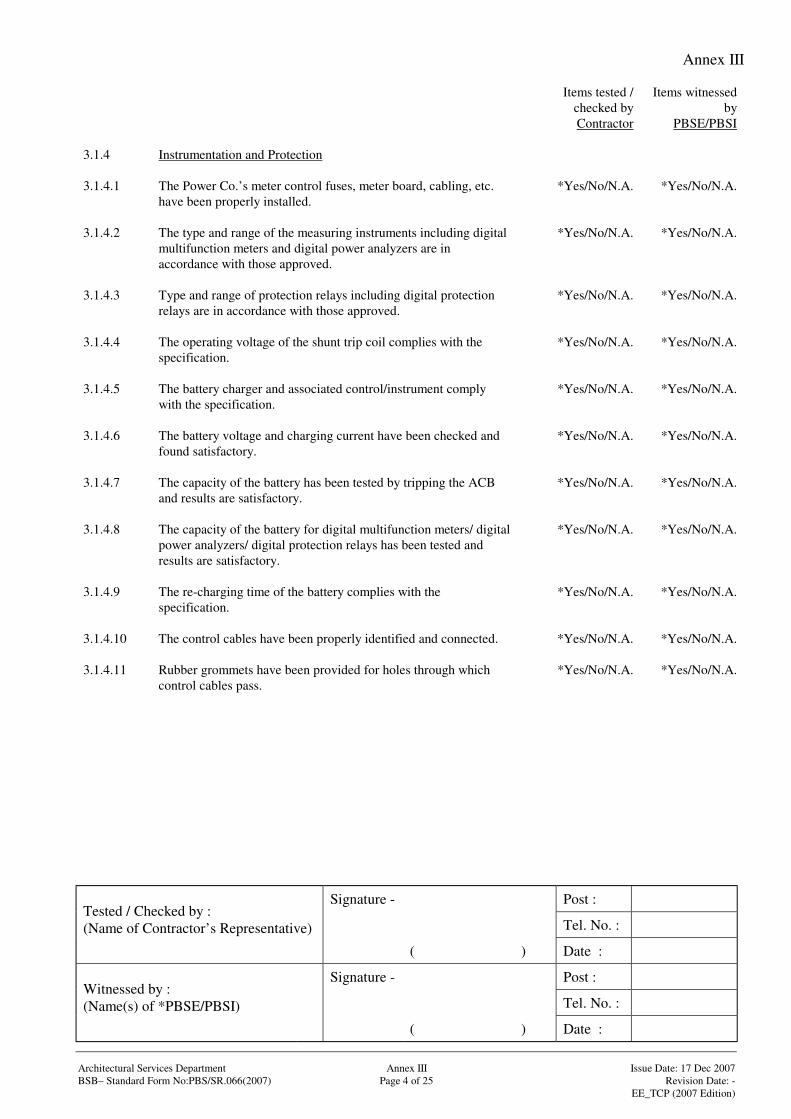
Annex III
Signature - Post :
Tel. No. :Tested / Checked by :(Name of Contractor’s Representative)
( ) Date :
Signature - Post :
Tel. No. :Witnessed by :(Name(s) of *PBSE/PBSI)
( ) Date :
Architectural Services Department Annex III Issue Date: 17 Dec 2007BSB– Standard Form No:PBS/SR.066(2007) Page 4 of 25 Revision Date: -
EE_TCP (2007 Edition)
Items tested /checked byContractor
Items witnessedby
PBSE/PBSI
3.1.4 Instrumentation and Protection
3.1.4.1 The Power Co.’s meter control fuses, meter board, cabling, etc.have been properly installed.
*Yes/No/N.A. *Yes/No/N.A.
3.1.4.2 The type and range of the measuring instruments including digitalmultifunction meters and digital power analyzers are inaccordance with those approved.
*Yes/No/N.A. *Yes/No/N.A.
3.1.4.3 Type and range of protection relays including digital protectionrelays are in accordance with those approved.
*Yes/No/N.A. *Yes/No/N.A.
3.1.4.4 The operating voltage of the shunt trip coil complies with thespecification.
*Yes/No/N.A. *Yes/No/N.A.
3.1.4.5 The battery charger and associated control/instrument complywith the specification.
*Yes/No/N.A. *Yes/No/N.A.
3.1.4.6 The battery voltage and charging current have been checked andfound satisfactory.
*Yes/No/N.A. *Yes/No/N.A.
3.1.4.7 The capacity of the battery has been tested by tripping the ACBand results are satisfactory.
*Yes/No/N.A. *Yes/No/N.A.
3.1.4.8 The capacity of the battery for digital multifunction meters/ digitalpower analyzers/ digital protection relays has been tested andresults are satisfactory.
*Yes/No/N.A. *Yes/No/N.A.
3.1.4.9 The re-charging time of the battery complies with thespecification.
*Yes/No/N.A. *Yes/No/N.A.
3.1.4.10 The control cables have been properly identified and connected. *Yes/No/N.A. *Yes/No/N.A.
3.1.4.11 Rubber grommets have been provided for holes through whichcontrol cables pass.
*Yes/No/N.A. *Yes/No/N.A.
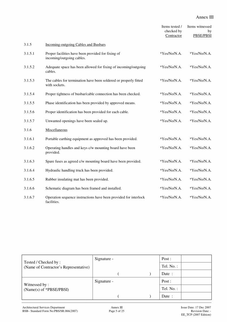
Annex III
Signature - Post :
Tel. No. :Tested / Checked by :(Name of Contractor’s Representative)
( ) Date :
Signature - Post :
Tel. No. :Witnessed by :(Name(s) of *PBSE/PBSI)
( ) Date :
Architectural Services Department Annex III Issue Date: 17 Dec 2007BSB– Standard Form No:PBS/SR.066(2007) Page 5 of 25 Revision Date: -
EE_TCP (2007 Edition)
Items tested /checked byContractor
Items witnessedby
PBSE/PBSI
3.1.5 Incoming-outgoing Cables and Busbars
3.1.5.1 Proper facilities have been provided for fixing ofincoming/outgoing cables.
*Yes/No/N.A. *Yes/No/N.A.
3.1.5.2 Adequate space has been allowed for fixing of incoming/outgoingcables.
*Yes/No/N.A. *Yes/No/N.A.
3.1.5.3 The cables for termination have been soldered or properly fittedwith sockets.
*Yes/No/N.A. *Yes/No/N.A.
3.1.5.4 Proper tightness of busbar/cable connection has been checked. *Yes/No/N.A. *Yes/No/N.A.
3.1.5.5 Phase identification has been provided by approved means. *Yes/No/N.A. *Yes/No/N.A.
3.1.5.6 Proper identification has been provided for each cable. *Yes/No/N.A. *Yes/No/N.A.
3.1.5.7 Unwanted openings have been sealed up. *Yes/No/N.A. *Yes/No/N.A.
3.1.6 Miscellaneous
3.1.6.1 Portable earthing equipment as approved has been provided. *Yes/No/N.A. *Yes/No/N.A.
3.1.6.2 Operating handles and keys c/w mounting board have beenprovided.
*Yes/No/N.A. *Yes/No/N.A.
3.1.6.3 Spare fuses as agreed c/w mounting board have been provided. *Yes/No/N.A. *Yes/No/N.A.
3.1.6.4 Hydraulic handling truck has been provided. *Yes/No/N.A. *Yes/No/N.A.
3.1.6.5 Rubber insulating mat has been provided. *Yes/No/N.A. *Yes/No/N.A.
3.1.6.6 Schematic diagram has been framed and installed. *Yes/No/N.A. *Yes/No/N.A.
3.1.6.7 Operation sequence instructions have been provided for interlockfacilities.
*Yes/No/N.A. *Yes/No/N.A.
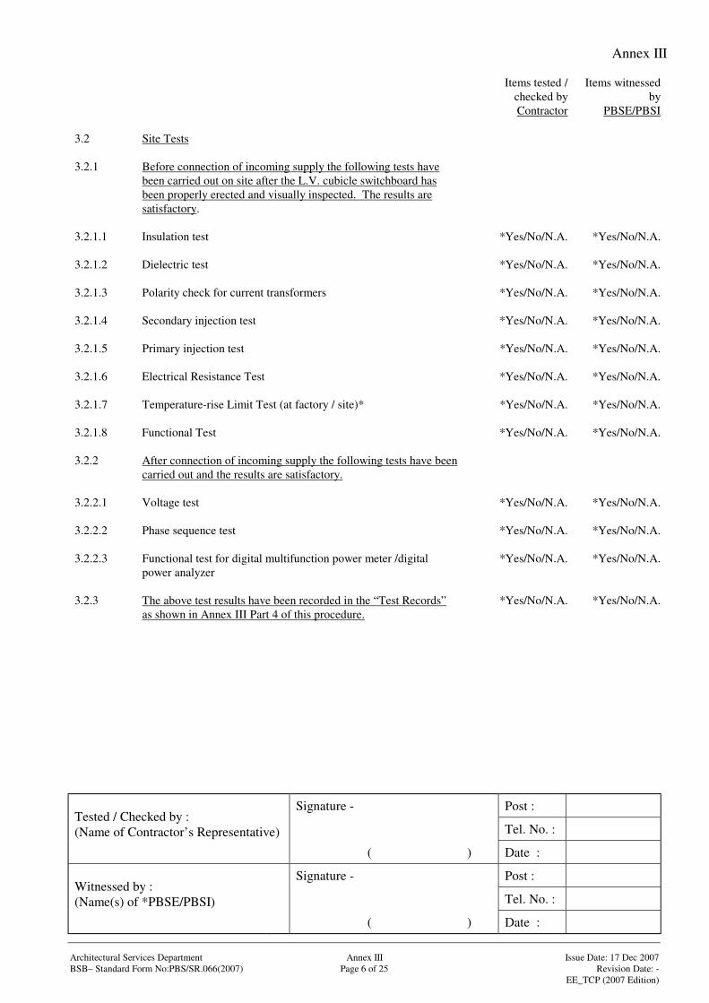
Annex III
Signature - Post :
Tel. No. :Tested / Checked by :(Name of Contractor’s Representative)
( ) Date :
Signature - Post :
Tel. No. :Witnessed by :(Name(s) of *PBSE/PBSI)
( ) Date :
Architectural Services Department Annex III Issue Date: 17 Dec 2007BSB– Standard Form No:PBS/SR.066(2007) Page 6 of 25 Revision Date: -
EE_TCP (2007 Edition)
Items tested /checked byContractor
Items witnessedby
PBSE/PBSI
3.2 Site Tests
3.2.1 Before connection of incoming supply the following tests havebeen carried out on site after the L.V. cubicle switchboard hasbeen properly erected and visually inspected. The results aresatisfactory.
3.2.1.1 Insulation test *Yes/No/N.A. *Yes/No/N.A.
3.2.1.2 Dielectric test *Yes/No/N.A. *Yes/No/N.A.
3.2.1.3 Polarity check for current transformers *Yes/No/N.A. *Yes/No/N.A.
3.2.1.4 Secondary injection test *Yes/No/N.A. *Yes/No/N.A.
3.2.1.5 Primary injection test *Yes/No/N.A. *Yes/No/N.A.
3.2.1.6 Electrical Resistance Test *Yes/No/N.A. *Yes/No/N.A.
3.2.1.7 Temperature-rise Limit Test (at factory / site)* *Yes/No/N.A. *Yes/No/N.A.
3.2.1.8 Functional Test *Yes/No/N.A. *Yes/No/N.A.
3.2.2 After connection of incoming supply the following tests have beencarried out and the results are satisfactory.
3.2.2.1 Voltage test *Yes/No/N.A. *Yes/No/N.A.
3.2.2.2 Phase sequence test *Yes/No/N.A. *Yes/No/N.A.
3.2.2.3 Functional test for digital multifunction power meter /digitalpower analyzer
*Yes/No/N.A. *Yes/No/N.A.
3.2.3 The above test results have been recorded in the “Test Records”as shown in Annex III Part 4 of this procedure.
*Yes/No/N.A. *Yes/No/N.A.
Annex III
Signature - Post :
Tel. No. :Tested / Checked by :(Name of Contractor’s Representative)
( ) Date :
Signature - Post :
Tel. No. :Witnessed by :(Name(s) of *PBSE/PBSI)
( ) Date :
Architectural Services Department Annex III Issue Date: 17 Dec 2007BSB– Standard Form No:PBS/SR.066(2007) Page 7 of 25 Revision Date: -
EE_TCP (2007 Edition)
Items tested /checked byContractor
Items witnessedby
PBSE/PBSI
3.3 Any other tests that are considered necessary to meet the designintent.
Annex III
Signature - Post :
Tel. No. :Tested / Checked by :(Name of Contractor’s Representative)
( ) Date :
Signature - Post :
Tel. No. :Witnessed by :(Name(s) of *PBSE/PBSI)
( ) Date :
Architectural Services Department Annex III Issue Date: 17 Dec 2007BSB– Standard Form No:PBS/SR.066(2007) Page 8 of 25 Revision Date: -
EE_TCP (2007 Edition)
Items tested /checked byContractor
Items witnessedby
PBSE/PBSI
3.4 Comments
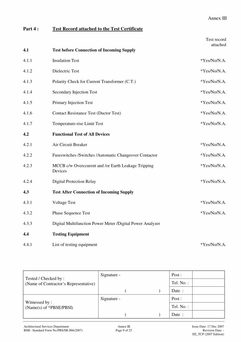
Annex III
Signature - Post :
Tel. No. :Tested / Checked by :(Name of Contractor’s Representative)
( ) Date :
Signature - Post :
Tel. No. :Witnessed by :(Name(s) of *PBSE/PBSI)
( ) Date :
Architectural Services Department Annex III Issue Date: 17 Dec 2007BSB– Standard Form No:PBS/SR.066(2007) Page 9 of 25 Revision Date: -
EE_TCP (2007 Edition)
Part 4 : Test Record attached to the Test Certificate
Test recordattached
4.1 Test before Connection of Incoming Supply
4.1.1 Insulation Test *Yes/No/N.A.
4.1.2 Dielectric Test *Yes/No/N.A.
4.1.3 Polarity Check for Current Transformer (C.T.) *Yes/No/N.A.
4.1.4 Secondary Injection Test *Yes/No/N.A.
4.1.5 Primary Injection Test *Yes/No/N.A.
4.1.6 Contact Resistance Test (Ductor Test) *Yes/No/N.A.
4.1.7 Temperature-rise Limit Test *Yes/No/N.A.
4.2 Functional Test of All Devices
4.2.1 Air Circuit Breaker *Yes/No/N.A.
4.2.2 Fuseswitches /Switches /Automatic Changeover Contactor *Yes/No/N.A.
4.2.3 MCCB c/w Overccurent and /or Earth Leakage TrippingDevices
*Yes/No/N.A.
4.2.4 Digital Protection Relay *Yes/No/N.A.
4.3 Test After Connection of Incoming Supply
4.3.1 Voltage Test *Yes/No/N.A.
4.3.2 Phase Sequence Test *Yes/No/N.A.
4.3.3 Digital Multifunction Power Meter /Digital Power Analyzer
4.4 Testing Equipment
4.4.1 List of testing equipment *Yes/No/N.A.
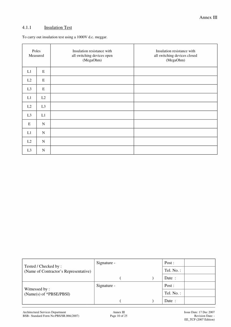
Annex III
Signature - Post :
Tel. No. :Tested / Checked by :(Name of Contractor’s Representative)
( ) Date :
Signature - Post :
Tel. No. :Witnessed by :(Name(s) of *PBSE/PBSI)
( ) Date :
Architectural Services Department Annex III Issue Date: 17 Dec 2007BSB– Standard Form No:PBS/SR.066(2007) Page 10 of 25 Revision Date: -
EE_TCP (2007 Edition)
4.1.1 Insulation Test
To carry out insulation test using a 1000V d.c. meggar.
PolesMeasured
Insulation resistance withall switching devices open
(MegaOhm)
Insulation resistance withall switching devices closed
(MegaOhm)
L1 E
L2 E
L3 E
L1 L2
L2 L3
L3 L1
E N
L1 N
L2 N
L3 N
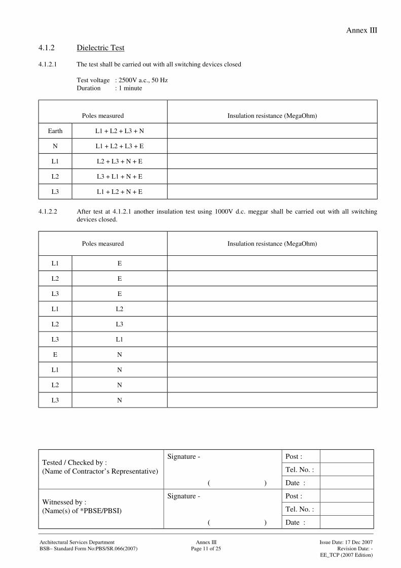
Annex III
Signature - Post :
Tel. No. :Tested / Checked by :(Name of Contractor’s Representative)
( ) Date :
Signature - Post :
Tel. No. :Witnessed by :(Name(s) of *PBSE/PBSI)
( ) Date :
Architectural Services Department Annex III Issue Date: 17 Dec 2007BSB– Standard Form No:PBS/SR.066(2007) Page 11 of 25 Revision Date: -
EE_TCP (2007 Edition)
4.1.2 Dielectric Test
4.1.2.1 The test shall be carried out with all switching devices closed
Test voltage : 2500V a.c., 50 HzDuration : 1 minute
Poles measured Insulation resistance (MegaOhm)
Earth L1 + L2 + L3 + N
N L1 + L2 + L3 + E
L1 L2 + L3 + N + E
L2 L3 + L1 + N + E
L3 L1 + L2 + N + E
4.1.2.2 After test at 4.1.2.1 another insulation test using 1000V d.c. meggar shall be carried out with all switchingdevices closed.
Poles measured Insulation resistance (MegaOhm)
L1 E
L2 E
L3 E
L1 L2
L2 L3
L3 L1
E N
L1 N
L2 N
L3 N
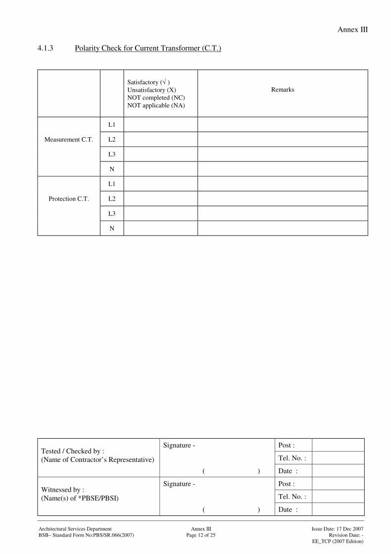
Annex III
Signature - Post :
Tel. No. :Tested / Checked by :(Name of Contractor’s Representative)
( ) Date :
Signature - Post :
Tel. No. :Witnessed by :(Name(s) of *PBSE/PBSI)
( ) Date :
Architectural Services Department Annex III Issue Date: 17 Dec 2007BSB– Standard Form No:PBS/SR.066(2007) Page 12 of 25 Revision Date: -
EE_TCP (2007 Edition)
4.1.3 Polarity Check for Current Transformer (C.T.)
Satisfactory (√ )Unsatisfactory (X)NOT completed (NC)NOT applicable (NA)
Remarks
L1
Measurement C.T. L2
L3
N
L1
Protection C.T. L2
L3
N
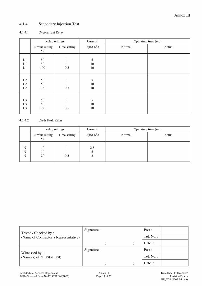
Annex III
Signature - Post :
Tel. No. :Tested / Checked by :(Name of Contractor’s Representative)
( ) Date :
Signature - Post :
Tel. No. :Witnessed by :(Name(s) of *PBSE/PBSI)
( ) Date :
Architectural Services Department Annex III Issue Date: 17 Dec 2007BSB– Standard Form No:PBS/SR.066(2007) Page 13 of 25 Revision Date: -
EE_TCP (2007 Edition)
4.1.4 Secondary Injection Test
4.1.4.1 Overcurrent Relay
Relay settings Operating time (sec)
Current setting%
Time setting
Current
inject (A) Normal Actual
L1L1L1
5050
100
11
0.5
51010
L2L2L2
5050
100
11
0.5
51010
L3L3L3
5050
100
11
0.5
51010
4.1.4.2 Earth Fault Relay
Relay settings Operating time (sec)
Current setting%
Time setting
Current
inject (A) Normal Actual
NNN
101020
11
0.5
2.552
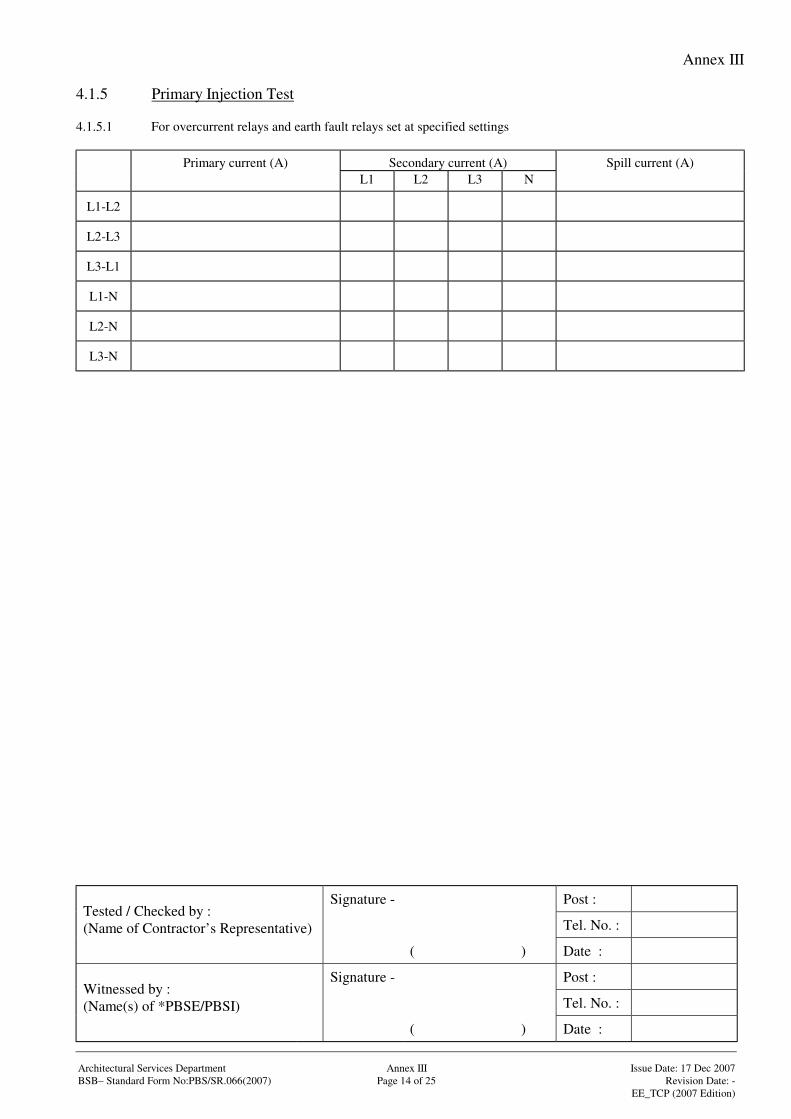
Annex III
Signature - Post :
Tel. No. :Tested / Checked by :(Name of Contractor’s Representative)
( ) Date :
Signature - Post :
Tel. No. :Witnessed by :(Name(s) of *PBSE/PBSI)
( ) Date :
Architectural Services Department Annex III Issue Date: 17 Dec 2007BSB– Standard Form No:PBS/SR.066(2007) Page 14 of 25 Revision Date: -
EE_TCP (2007 Edition)
4.1.5 Primary Injection Test
4.1.5.1 For overcurrent relays and earth fault relays set at specified settings
Secondary current (A)Primary current (A)L1 L2 L3 N
Spill current (A)
L1-L2
L2-L3
L3-L1
L1-N
L2-N
L3-N
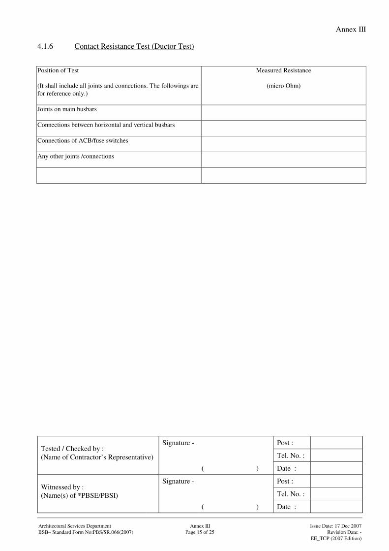
Annex III
Signature - Post :
Tel. No. :Tested / Checked by :(Name of Contractor’s Representative)
( ) Date :
Signature - Post :
Tel. No. :Witnessed by :(Name(s) of *PBSE/PBSI)
( ) Date :
Architectural Services Department Annex III Issue Date: 17 Dec 2007BSB– Standard Form No:PBS/SR.066(2007) Page 15 of 25 Revision Date: -
EE_TCP (2007 Edition)
4.1.6 Contact Resistance Test (Ductor Test)
Position of Test
(It shall include all joints and connections. The followings arefor reference only.)
Measured Resistance
(micro Ohm)
Joints on main busbars
Connections between horizontal and vertical busbars
Connections of ACB/fuse switches
Any other joints /connections
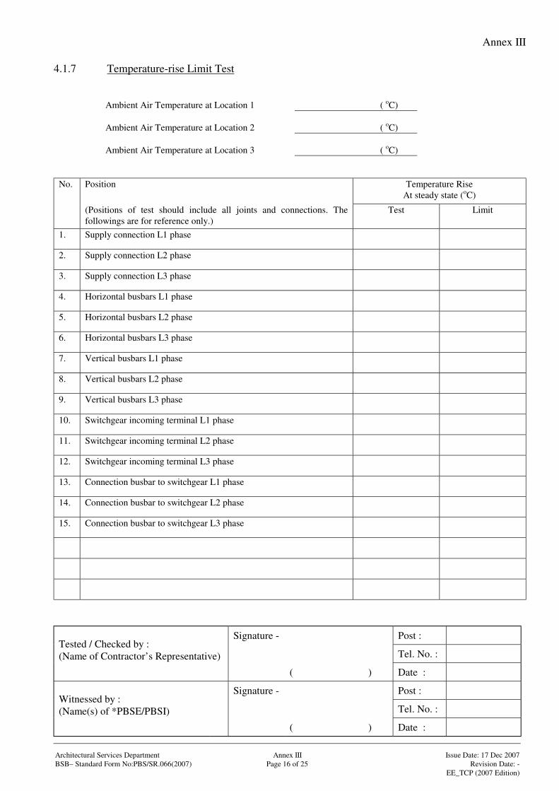
Annex III
Signature - Post :
Tel. No. :Tested / Checked by :(Name of Contractor’s Representative)
( ) Date :
Signature - Post :
Tel. No. :Witnessed by :(Name(s) of *PBSE/PBSI)
( ) Date :
Architectural Services Department Annex III Issue Date: 17 Dec 2007BSB– Standard Form No:PBS/SR.066(2007) Page 16 of 25 Revision Date: -
EE_TCP (2007 Edition)
4.1.7 Temperature-rise Limit Test
Ambient Air Temperature at Location 1 ( oC)
Ambient Air Temperature at Location 2 ( oC)
Ambient Air Temperature at Location 3 ( oC)
No. Position Temperature RiseAt steady state (oC)
(Positions of test should include all joints and connections. Thefollowings are for reference only.)
Test Limit
1. Supply connection L1 phase
2. Supply connection L2 phase
3. Supply connection L3 phase
4. Horizontal busbars L1 phase
5. Horizontal busbars L2 phase
6. Horizontal busbars L3 phase
7. Vertical busbars L1 phase
8. Vertical busbars L2 phase
9. Vertical busbars L3 phase
10. Switchgear incoming terminal L1 phase
11. Switchgear incoming terminal L2 phase
12. Switchgear incoming terminal L3 phase
13. Connection busbar to switchgear L1 phase
14. Connection busbar to switchgear L2 phase
15. Connection busbar to switchgear L3 phase
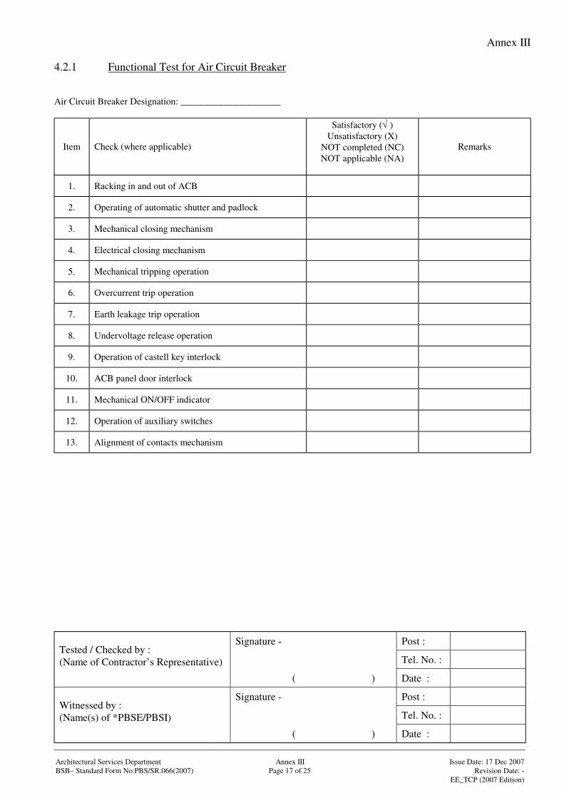
Annex III
Signature - Post :
Tel. No. :Tested / Checked by :(Name of Contractor’s Representative)
( ) Date :
Signature - Post :
Tel. No. :Witnessed by :(Name(s) of *PBSE/PBSI)
( ) Date :
Architectural Services Department Annex III Issue Date: 17 Dec 2007BSB– Standard Form No:PBS/SR.066(2007) Page 17 of 25 Revision Date: -
EE_TCP (2007 Edition)
4.2.1 Functional Test for Air Circuit Breaker
Air Circuit Breaker Designation: _____________________
Item Check (where applicable)
Satisfactory (√ )Unsatisfactory (X)
NOT completed (NC)NOT applicable (NA)
Remarks
1. Racking in and out of ACB
2. Operating of automatic shutter and padlock
3. Mechanical closing mechanism
4. Electrical closing mechanism
5. Mechanical tripping operation
6. Overcurrent trip operation
7. Earth leakage trip operation
8. Undervoltage release operation
9. Operation of castell key interlock
10. ACB panel door interlock
11. Mechanical ON/OFF indicator
12. Operation of auxiliary switches
13. Alignment of contacts mechanism
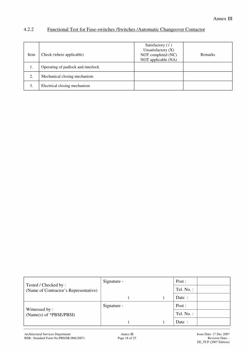
Annex III
Signature - Post :
Tel. No. :Tested / Checked by :(Name of Contractor’s Representative)
( ) Date :
Signature - Post :
Tel. No. :Witnessed by :(Name(s) of *PBSE/PBSI)
( ) Date :
Architectural Services Department Annex III Issue Date: 17 Dec 2007BSB– Standard Form No:PBS/SR.066(2007) Page 18 of 25 Revision Date: -
EE_TCP (2007 Edition)
4.2.2 Functional Test for Fuse-switches /Switches /Automatic Changeover Contactor
Item Check (where applicable)
Satisfactory (√ )Unsatisfactory (X)
NOT completed (NC)NOT applicable (NA)
Remarks
1. Operating of padlock and interlock
2. Mechanical closing mechanism
3. Electrical closing mechanism
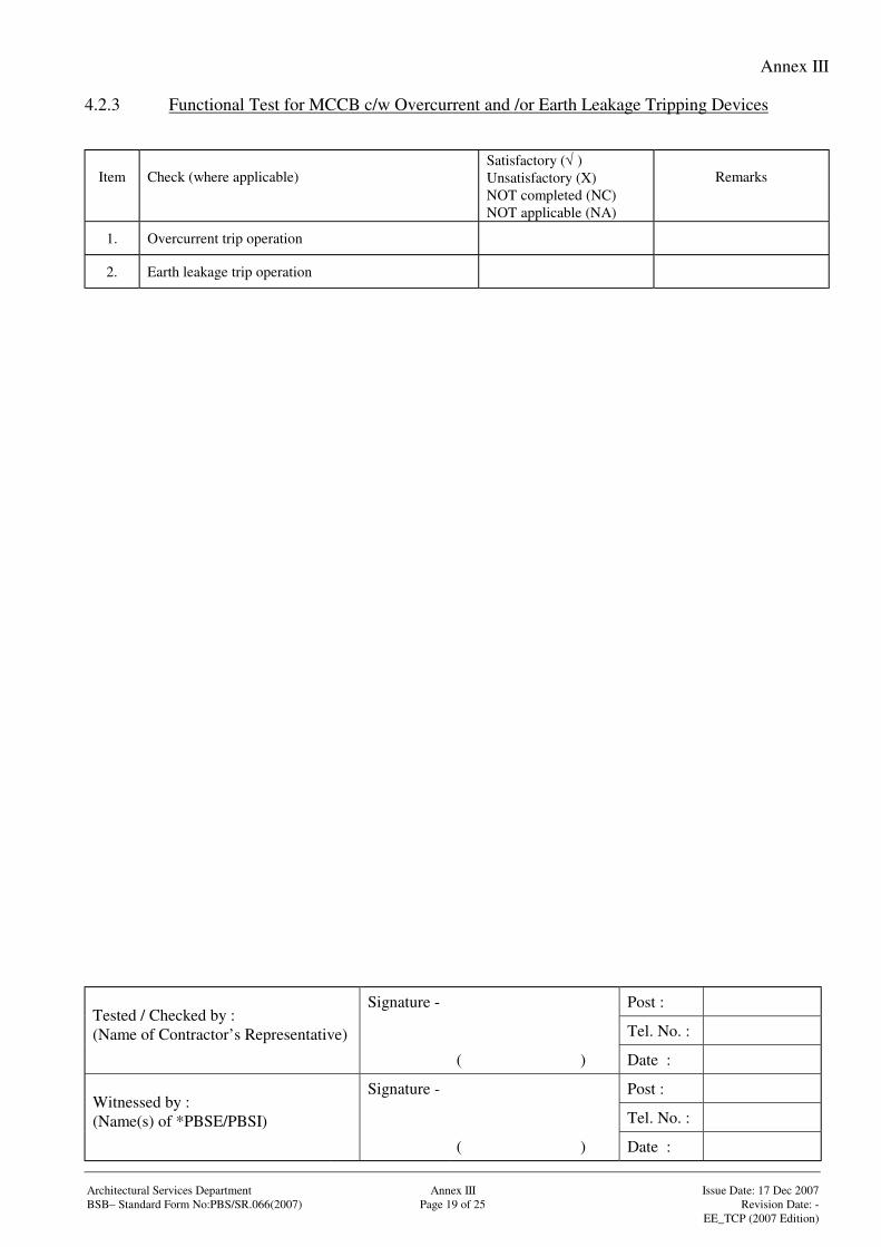
Annex III
Signature - Post :
Tel. No. :Tested / Checked by :(Name of Contractor’s Representative)
( ) Date :
Signature - Post :
Tel. No. :Witnessed by :(Name(s) of *PBSE/PBSI)
( ) Date :
Architectural Services Department Annex III Issue Date: 17 Dec 2007BSB– Standard Form No:PBS/SR.066(2007) Page 19 of 25 Revision Date: -
EE_TCP (2007 Edition)
4.2.3 Functional Test for MCCB c/w Overcurrent and /or Earth Leakage Tripping Devices
Item Check (where applicable)Satisfactory (√ )Unsatisfactory (X)NOT completed (NC)NOT applicable (NA)
Remarks
1. Overcurrent trip operation
2. Earth leakage trip operation
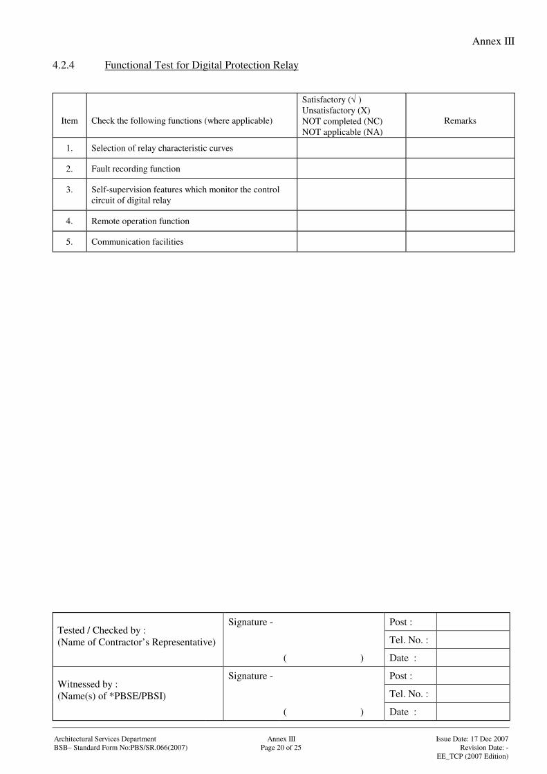
Annex III
Signature - Post :
Tel. No. :Tested / Checked by :(Name of Contractor’s Representative)
( ) Date :
Signature - Post :
Tel. No. :Witnessed by :(Name(s) of *PBSE/PBSI)
( ) Date :
Architectural Services Department Annex III Issue Date: 17 Dec 2007BSB– Standard Form No:PBS/SR.066(2007) Page 20 of 25 Revision Date: -
EE_TCP (2007 Edition)
4.2.4 Functional Test for Digital Protection Relay
Item Check the following functions (where applicable)
Satisfactory (√ )Unsatisfactory (X)NOT completed (NC)NOT applicable (NA)
Remarks
1. Selection of relay characteristic curves
2. Fault recording function
3. Self-supervision features which monitor the controlcircuit of digital relay
4. Remote operation function
5. Communication facilities
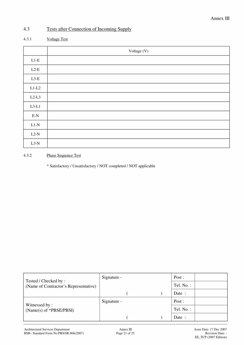
Annex III
Signature - Post :
Tel. No. :Tested / Checked by :(Name of Contractor’s Representative)
( ) Date :
Signature - Post :
Tel. No. :Witnessed by :(Name(s) of *PBSE/PBSI)
( ) Date :
Architectural Services Department Annex III Issue Date: 17 Dec 2007BSB– Standard Form No:PBS/SR.066(2007) Page 21 of 25 Revision Date: -
EE_TCP (2007 Edition)
4.3 Tests after Connection of Incoming Supply
4.3.1 Voltage Test
Voltage (V)
L1-E
L2-E
L3-E
L1-L2
L2-L3
L3-L1
E-N
L1-N
L2-N
L3-N
4.3.2 Phase Sequence Test
* Satisfactory / Unsatisfactory / NOT completed / NOT applicable
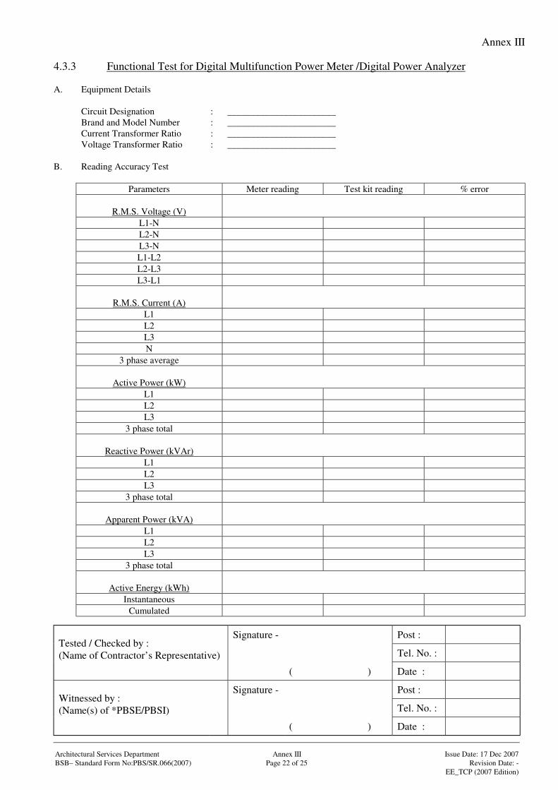
Annex III
Signature - Post :
Tel. No. :Tested / Checked by :(Name of Contractor’s Representative)
( ) Date :
Signature - Post :
Tel. No. :Witnessed by :(Name(s) of *PBSE/PBSI)
( ) Date :
Architectural Services Department Annex III Issue Date: 17 Dec 2007BSB– Standard Form No:PBS/SR.066(2007) Page 22 of 25 Revision Date: -
EE_TCP (2007 Edition)
4.3.3 Functional Test for Digital Multifunction Power Meter /Digital Power Analyzer
A. Equipment Details
Circuit Designation : _______________________Brand and Model Number : _______________________Current Transformer Ratio : _______________________Voltage Transformer Ratio : _______________________
B. Reading Accuracy Test
Parameters Meter reading Test kit reading % error
R.M.S. Voltage (V)L1-NL2-NL3-NL1-L2L2-L3L3-L1
R.M.S. Current (A)L1L2L3N
3 phase average
Active Power (kW)L1L2L3
3 phase total
Reactive Power (kVAr)L1L2L3
3 phase total
Apparent Power (kVA)L1L2L3
3 phase total
Active Energy (kWh)Instantaneous
Cumulated
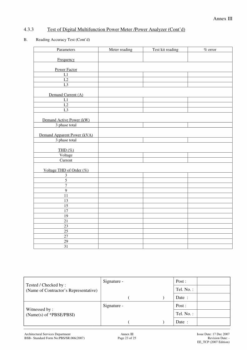
Annex III
Signature - Post :
Tel. No. :Tested / Checked by :(Name of Contractor’s Representative)
( ) Date :
Signature - Post :
Tel. No. :Witnessed by :(Name(s) of *PBSE/PBSI)
( ) Date :
Architectural Services Department Annex III Issue Date: 17 Dec 2007BSB– Standard Form No:PBS/SR.066(2007) Page 23 of 25 Revision Date: -
EE_TCP (2007 Edition)
4.3.3 Test of Digital Multifunction Power Meter /Power Analyzer (Cont’d)
B. Reading Accuracy Test (Cont’d)
Parameters Meter reading Test kit reading % error
Frequency
Power FactorL1L2L3
Demand Current (A)L1L2L3
Demand Active Power (kW)3 phase total
Demand Apparent Power (kVA)3 phase total
THD (%)VoltageCurrent
Voltage THD of Order (%)3579
1113151719212325272931
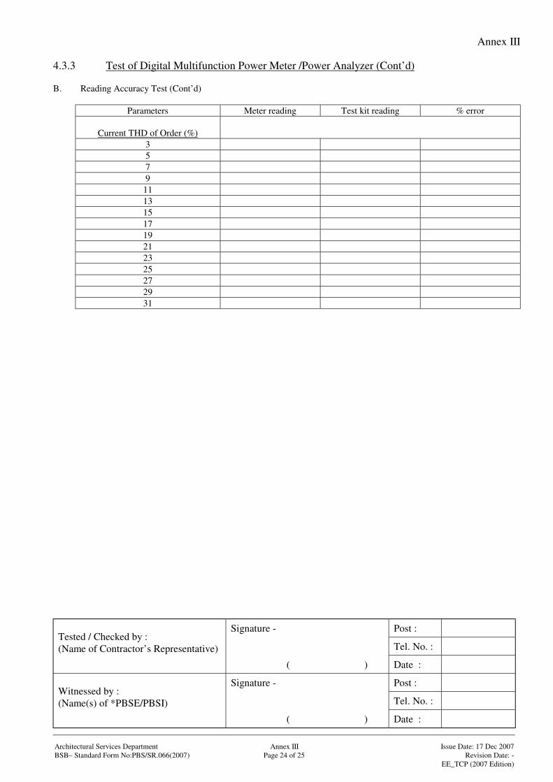
Annex III
Signature - Post :
Tel. No. :Tested / Checked by :(Name of Contractor’s Representative)
( ) Date :
Signature - Post :
Tel. No. :Witnessed by :(Name(s) of *PBSE/PBSI)
( ) Date :
Architectural Services Department Annex III Issue Date: 17 Dec 2007BSB– Standard Form No:PBS/SR.066(2007) Page 24 of 25 Revision Date: -
EE_TCP (2007 Edition)
4.3.3 Test of Digital Multifunction Power Meter /Power Analyzer (Cont’d)
B. Reading Accuracy Test (Cont’d)
Parameters Meter reading Test kit reading % error
Current THD of Order (%)3579
1113151719212325272931
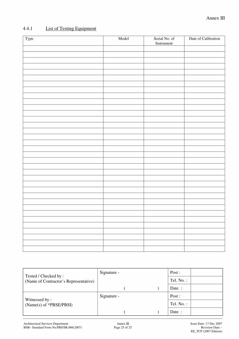
Annex III
Signature - Post :
Tel. No. :Tested / Checked by :(Name of Contractor’s Representative)
( ) Date :
Signature - Post :
Tel. No. :Witnessed by :(Name(s) of *PBSE/PBSI)
( ) Date :
Architectural Services Department Annex III Issue Date: 17 Dec 2007BSB– Standard Form No:PBS/SR.066(2007) Page 25 of 25 Revision Date: -
EE_TCP (2007 Edition)
4.4.1 List of Testing Equipment
Type Model Serial No. ofInstrument
Date of Calibration
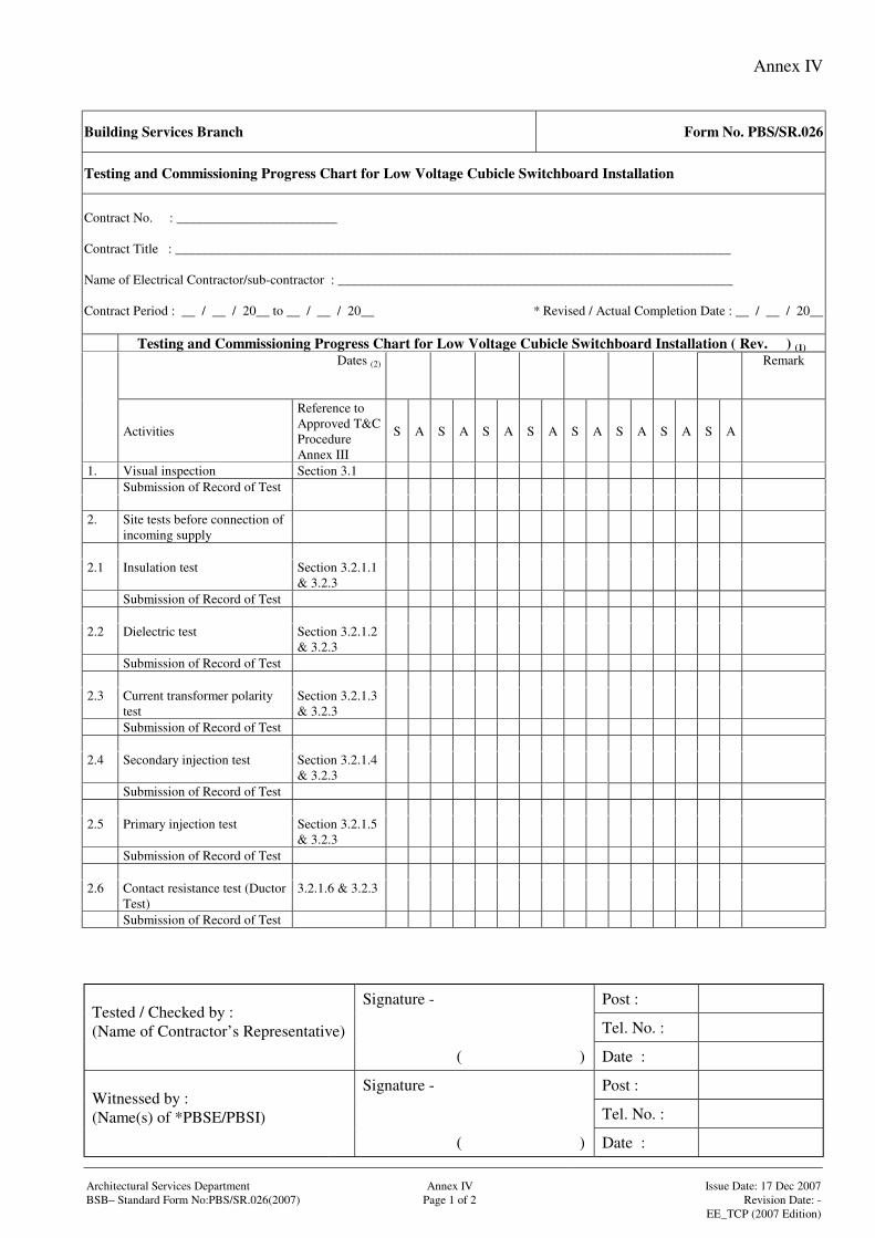
Annex IV
Signature - Post :
Tel. No. :Tested / Checked by :(Name of Contractor’s Representative)
( ) Date :
Signature - Post :
Tel. No. :Witnessed by :(Name(s) of *PBSE/PBSI)
( ) Date :
Architectural Services Department Annex IV Issue Date: 17 Dec 2007BSB– Standard Form No:PBS/SR.026(2007) Page 1 of 2 Revision Date: -
EE_TCP (2007 Edition)
Building Services Branch Form No. PBS/SR.026
Testing and Commissioning Progress Chart for Low Voltage Cubicle Switchboard Installation
Contract No. : ________________________
Contract Title : ___________________________________________________________________________________
Name of Electrical Contractor/sub-contractor : ___________________________________________________________
Contract Period : __ / __ / 20__ to __ / __ / 20__ * Revised / Actual Completion Date : __ / __ / 20__
Testing and Commissioning Progress Chart for Low Voltage Cubicle Switchboard Installation ( Rev. ) (1)
Dates (2) Remark
Activities
Reference toApproved T&CProcedureAnnex III
S A S A S A S A S A S A S A S A
1. Visual inspection Section 3.1Submission of Record of Test
2. Site tests before connection ofincoming supply
2.1 Insulation test Section 3.2.1.1& 3.2.3
Submission of Record of Test
2.2 Dielectric test Section 3.2.1.2& 3.2.3
Submission of Record of Test
2.3 Current transformer polaritytest
Section 3.2.1.3& 3.2.3
Submission of Record of Test
2.4 Secondary injection test Section 3.2.1.4& 3.2.3
Submission of Record of Test
2.5 Primary injection test Section 3.2.1.5& 3.2.3
Submission of Record of Test
2.6 Contact resistance test (DuctorTest)
3.2.1.6 & 3.2.3
Submission of Record of Test
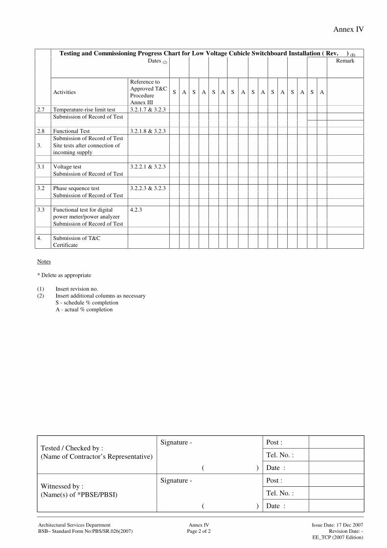
Annex IV
Signature - Post :
Tel. No. :Tested / Checked by :(Name of Contractor’s Representative)
( ) Date :
Signature - Post :
Tel. No. :Witnessed by :(Name(s) of *PBSE/PBSI)
( ) Date :
Architectural Services Department Annex IV Issue Date: 17 Dec 2007BSB– Standard Form No:PBS/SR.026(2007) Page 2 of 2 Revision Date: -
EE_TCP (2007 Edition)
Testing and Commissioning Progress Chart for Low Voltage Cubicle Switchboard Installation ( Rev. ) (1)
Dates (2) Remark
Activities
Reference toApproved T&CProcedureAnnex III
S A S A S A S A S A S A S A S A
2.7 Temperature-rise limit test 3.2.1.7 & 3.2.3Submission of Record of Test
2.8 Functional Test 3.2.1.8 & 3.2.3Submission of Record of Test
3. Site tests after connection ofincoming supply
3.1 Voltage test 3.2.2.1 & 3.2.3Submission of Record of Test
3.2 Phase sequence test 3.2.2.3 & 3.2.3Submission of Record of Test
3.3 Functional test for digitalpower meter/power analyzer
4.2.3
Submission of Record of Test
4. Submission of T&CCertificate
Notes
* Delete as appropriate
(1) Insert revision no.(2) Insert additional columns as necessary
S - schedule % completionA - actual % completion
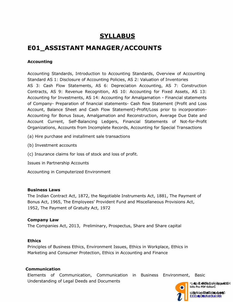
SYLLABUS
E01_ASSISTANT MANAGER/ACCOUNTS
Accounting
Accounting Standards, Introduction to Accounting Standards, Overview of Accounting
Standard AS 1: Disclosure of Accounting Policies, AS 2: Valuation of Inventories
AS 3: Cash Flow Statements, AS 6: Depreciation Accounting, AS 7: Construction
Contracts, AS 9: Revenue Recognition, AS 10: Accounting for Fixed Assets, AS 13:
Accounting for Investments, AS 14: Accounting for Amalgamation - Financial statements
of Company- Preparation of financial statements- Cash flow Statement (Profit and Loss
Account, Balance Sheet and Cash Flow Statement)-Profit/Loss prior to incorporation-
Accounting for Bonus Issue, Amalgamation and Reconstruction, Average Due Date and
Account Current, Self-Balancing Ledgers, Financial Statements of Not-for-Profit
Organizations, Accounts from Incomplete Records, Accounting for Special Transactions
(a) Hire purchase and installment sale transactions
(b) Investment accounts
(c) Insurance claims for loss of stock and loss of profit.
Issues in Partnership Accounts
Accounting in Computerized Environment
Business Laws
The Indian Contract Act, 1872, the Negotiable Instruments Act, 1881, The Payment of
Bonus Act, 1965, The Employees’ Provident Fund and Miscellaneous Provisions Act,
1952, The Payment of Gratuity Act, 1972
Company Law
The Companies Act, 2013, Preliminary, Prospectus, Share and Share capital
Ethics
Principles of Business Ethics, Environment Issues, Ethics in Workplace, Ethics in
Marketing and Consumer Protection, Ethics in Accounting and Finance
Communication
Elements of Communication, Communication in Business Environment, Basic
Understanding of Legal Deeds and Documents
Cost Accounting
Introduction to Cost Accounting, Materials, Labor, Overheads, Non-Integrated Accounts,
Methods, Job and Batch, Contract, Operating, Process and Operation, Standard Costing,
Marginal Costing, Budgets and Budgetary Control
Financial Management
Scope and Objectives of Financial Management, Time Value of Money, Financial Analysis
and Planning, Financing Decisions, Types of Financing, Investment Decisions,
Management of working capital
Income-tax
The Income-tax Act, 1961, Basic concepts, Residential status and scope of total income,
Incomes which do not form part of total income ( Sec 10), 5 Heads of income, Provisions
of Clubbing, Set-off and carry forward of losses, Deductions from gross total income,
Computation of total income and tax payable. Provisions concerning Advance tax and
TDS, Provisions for filing of return of income.
Service tax
Concepts and general principles, Charge of service tax and Valuation, Payment of
service tax and filing of returns
VAT
Concepts and general principles, Input Tax Credits and Composition Scheme for Small
Dealers, VAT Procedures
Advanced Accounting
Conceptual Framework for Preparation and Presentation of Financial Statements
Accounting Standards
AS 4: Contingencies and Events occurring after the Balance Sheet Date
AS 5: Net Profit or Loss for the Period, Prior Period Items and Changes in Accounting
Policies
AS 11: The Effects of Changes in Foreign Exchange Rates
AS 12: Accounting for Government Grants
AS 16: Borrowing Costs
AS 19: Leases
AS 20: Earnings per Share
AS 26: Intangible Assets
AS 29: Provisions, Contingent Liabilities and Contingent Assets
Advanced Issues in Partnership Accounts, Company Accounts, Employee stock option
plan and Buy back of securities, Amalgamation and Reconstruction, Underwriting of
shares and debentures, Redemption of debentures, Accounting for Special Transactions,
Insurance Companies, Banking Companies, Electricity Companies, Departmental
accounts, Branch accounts including foreign branches
Auditing and Assurance
Auditing Concepts, Auditing and Assurance Standards, Preparation for an Audit, Internal
Control, Vouching, Verification of Assets and Liabilities, Company Audit, Audit Report,
Special Audits
Information Technology
Computer software, Data Storage, Retrievals and Data Base Management Systems,
Computer Networks & Network Security, Internet and other technologies, Flowcharts,
Decision Tables
Strategic Management
Business Environment, Business Policy and Strategic Management, Strategic Analyses
Strategic Planning, Formulation of Functional Strategy, Strategy Implementation and
Control, Reaching Strategic Edge
NE01- Station Controller cum Train Operator (SCTO)
Electrical Engineering
Basic Electrical Engg. And Electt. Measurements:
Concepts of currents, Voltage, Resistance, Power and energy, their units, Ohm's law. Circuit Law: Kirchhoff’s law
Solution of simple network problems, Network theorems and their applications, Electro-magnetism concept of flux, Emf,
Reluctance, Magnetic circuits, Electro-magnetic induction, Self and mutual inductance.,A.C. fundamentals
Instantaneous, Peak, R.m.s. And average values of alternating waves, Equation of sinusoidal wave form, Simple series
and parallel a.c. Circuits consisting of R.L. and C. Resonance, Measurement and measuring instruments
Moving coil and moving iron ammeters and voltmeters, Extension of range, Watt meters, Multimeters, Megger, Basic
Electronics.
Electrical machines:
Basic principles D, C motors of generators, their characteristics, Speed control and starting of D.C. motors, Losses and
efficiency of D.C. machines.
1-phase and 3-phase Transformers:
Principles of Operation, Equivalent Circuit, Voltage Regulation O.C. And S.C. Tests, Efficiency, Auto Transformers,
Synchronous Machines, Generation Of Three Phase Emf, Armature Reaction, Voltage Regulation, Parallel Operation
Of Two Alternators, Synchronizing, Staring And Applications Of Synchronous Motors, 3-Phase Induction Motor,
Rotating Magnetic Field, Principle Of Operation, Equivalent Circuit, Torque Speed Characteristics, Starting And Speed
Control Of 3-Phase Induction Motors, Fractional Kw Motors, 1-Phase Induction Motors A.C. Series Motor, Reluctance
Motor.
General, Transmission and Distribution:
Different types of power stations, Load factor, Diversity factor, Demand factor, Simple problems thereon, Cost of
generation inter connection of power stations, Power factor improvement, Various types of tariffs, Types of faults
Short circuit current for symmetrical faults, Switchgears-rating of circuit breakers: Principles of a are extinction by oil
and air, H.R.C. fuses, Protection earthier leakage, Over current Buchhotgz relayMerz-Prince system of protection of
generators & transformers, Protection of feeders and bus bars., Lightning arresters, Various transmission and
distribution systems, Comparison of conductor materials. Efficiency for different systems.
Utilization of Electrical Energy:
Illumination, Electric heating, Electric welding, Electroplating, Electric drivers and motors.
NE01- Station Controller cum Train Operator(SCTO)
Electronics, Electronics & Telecommunication
Syllabus Electronics / Electronics & Telecommunication BASIC ELECTRICAL ENGINEERING Basic concepts and principles of D.C and A.C fundamental, A C circuits, batteries, electromagnetic induction etc. including constant voltage and current sources. ANALOG ELECTRONICS Fundamental concepts of basic electronics and basic understanding of conductors, semiconductors and insulators, extrinsic and intrinsic semi-conductors, p-n junction, need of rectifiers in electronics, understanding of filters in rectifiers, tunnel diodes, LEDs, varactor diodes, LCD; working of transistors in various configurations; Concept of FETs and MOSFET etc. CONTROL SYSTEMS Basic elements of control system, open loop control system, closed loop control system, control system terminology, manually controlled closed loop systems, automatic controlled closed loop systems, basic elements of a servo mechanism, Examples of automatic control systems, use of equivalent systems for system analysis, linear systems, non-linear systems, control system examples from chemical systems, mechanical systems, electrical systems, introduction to Laplace transform. Transfer function analysis of ac and dc servomotors synchros, stepper motor, amply dyne. ac position control system, magnetic amplifier. Control system representation: Transfer function, block diagram, reduction of block diagram, problems on block diagram, Mason’s formula signal flow graph Time Response Analysis : Standard test signals, time response of first and second -order system, time constant, time response of second order system, time response specifications, steady-state errors and error constants, problems in first and second order system. Stability: Routh Hurwitz Criterion, Root Locus, Bode Plotting using semi log graph paper Introduction to multiloop control system and its types, feedforward, cascade, ratio, split range, control system. Study of different processes using above mentioned control systems Non-Linear Control System : Introduction, behaviour of non-linear control system. Different types of nonlinearities, saturation, backlash, hysteris, dead zone, relay, fiction, characteristics of non-linear control system, limit cycles, jump resonance, jump phenomenon. Difference between linear and non-linear control system.
ELECTRONIC COMPONENTS AND MATERIALS Materials : Classification of materials , Conducting, semi-conducting and insulating materials through a brief reference to their atomic structure. Conducting Materials : Resistors and factors affecting resistivity such as temperature, alloying and mechanical stressing. Classification of conducting materials into low resistivity and high resistivity materials. Insulating Materials : Important relevant characteristics (electrical, mechanical and thermal) and applications of the following material: Mica, Glass, Copper, Sliver, PVC, Silicon, Rubber, Bakelite, Cotton, Ceramic, Polyester, Polythene and Varnish. Magnetic Materials : Different Magnetic materials; (Dia, Para, Ferro) and their properties. Ferro magnetism, Domains, permeability, Hysteresis loop. Soft and hard magnetic materials, their examples and typical applications. MEASURING INSTRUMENTS Introduction to Testing and Measurements, Measurement of Resistance, Inductance and Capacitance, Ammeter, Voltmeter and Multimeter, Power and Energy Measurements, Frequency and Phase difference Measurement PRINCIPLES OF INSTRUMENTATION Basic building blocks of any instrumentation systems, Performance characteristics of Oscillator Instruments, Instrument selection: Factors affecting instrument selection, accuracy, precision, linearity, resolution, sensitivity, hysteresis, reliability, serviceability, loading effect, range advantage and limitation, cost effectiveness and availability - Static and dynamic response - Environmental effects - Calibration tools FUNDAMENTALS OF DIGITAL ELECTRONICS Concepts of Digital electronics, Number system , gates, codes, arithmetic logic circuits, flip-flops, shift resistors and counters.
BASIC OF Microprocessors Architecture of a typical microprocessor, configurations and instructional pair configuration systems and working of various peripheral interface chips. 8085 Microprocessors, architecture, instruction sets and introduction to 8086. POWER ELECTRONICS Introduction to thyristors and other power Electronics devices, Controlled Converters, Inverters, Choppers. COMPUTER AIDED INSTRUMENTATION Computer aided Instrumentation, Buses and Standards : Introduction , BUS types : The I/O BUS a) ISA bus b) EISA Bus c) PCI bus , GPIB 2.5 RS-232, Linear Circuits and Signal Conditioning, Parallel Port (PP) Interfacing Techniques, Serial Port (SP) Interfacing Techniques, USB Port Interfacing Techniques. QUALITY AND RELIABILITY TECHNIQUES Quality organization and Management: Introduction, Quality Policy, Task for Quality and Introduction to Total Quality Systems Quality costs : Prevention costs, appraisal costs, internal failure costs, external failure costs, impact of quality costs on profitability
NE03- Jr. Engineer/ (Electrical)
Basic Electrical Engg. And Electt. Measurements:
Concepts of currents, Voltage, Resistance, Power and energy, their units, Ohm's law. Circuit Law: Kirchhoff’s law
Solution of simple network problems, Network theorems and their applications, Electro-magnetism concept of flux, Emf,
Reluctance, Magnetic circuits, Electro-magnetic induction, Self and mutual inductance.,A.C. fundamentals
Instantaneous, Peak, R.m.s. And average values of alternating waves, Equation of sinusoidal wave form, Simple series
and parallel a.c. Circuits consisting of R.L. and C. Resonance, Measurement and measuring instruments
Moving coil and moving iron ammeters and voltmeters, Extension of range, Watt meters, Multimeters, Megger, Basic
Electronics.
Electrical machines:
Basic principles D, C motors of generators, their characteristics, Speed control and starting of D.C. motors, Losses and
efficiency of D.C. machines.
1-phase and 3-phase Transformers:
Principles of Operation, Equivalent Circuit, Voltage Regulation O.C. And S.C. Tests, Efficiency, Auto Transformers,
Synchronous Machines, Generation Of Three Phase Emf, Armature Reaction, Voltage Regulation, Parallel Operation
Of Two Alternators, Synchronizing, Staring And Applications Of Synchronous Motors, 3-Phase Induction Motor,
Rotating Magnetic Field, Principle Of Operation, Equivalent Circuit, Torque Speed Characteristics, Starting And Speed
Control Of 3-Phase Induction Motors, Fractional Kw Motors, 1-Phase Induction Motors A.C. Series Motor, Reluctance
Motor.
General, Transmission and Distribution:
Different types of power stations, Load factor, Diversity factor, Demand factor, Simple problems thereon, Cost of
generation inter connection of power stations, Power factor improvement, Various types of tariffs, Types of faults
Short circuit current for symmetrical faults, Switchgears-rating of circuit breakers: Principles of a are extinction by oil
and air, H.R.C. fuses, Protection earthier leakage, Over current Buchhotgz relayMerz-Prince system of protection of
generators & transformers, Protection of feeders and bus bars., Lightning arresters, Various transmission and
distribution systems, Comparison of conductor materials. Efficiency for different systems.
Utilization of Electrical Energy:
Illumination, Electric heating, Electric welding, Electroplating, Electric drivers and motors.
NE04- Jr. Engineer/ (S&T)
BASIC ELECTRICAL ENGINEERING Basic concepts and principles of D.C and A.C fundamental, A C circuits, batteries, electromagnetic induction etc. including constant voltage and current sources. ANALOG ELECTRONICS Fundamental concepts of basic electronics and basic understanding of conductors, semiconductors and insulators, extrinsic and intrinsic semi-conductors, p-n junction, need of rectifiers in electronics, understanding of filters in rectifiers, tunnel diodes, LEDs, varactor diodes, LCD; working of transistors in various configurations; Concept of FETs and MOSFET etc. CONTROL SYSTEMS Basic elements of control system, open loop control system, closed loop control system, control system terminology, manually controlled closed loop systems, automatic controlled closed loop systems, basic elements of a servo mechanism, Examples of automatic control systems, use of equivalent systems for system analysis, linear systems, non-linear systems, control system examples from chemical systems, mechanical systems, electrical systems, introduction to Laplace transform. Transfer function analysis of ac and dc servomotors synchros, stepper motor, amply dyne. ac position control system, magnetic amplifier. Control system representation: Transfer function, block diagram, reduction of block diagram, problems on block diagram, Mason’s formula signal flow graph Time Response Analysis : Standard test signals, time response of first and second -order system, time constant, time response of second order system, time response specifications, steady-state errors and error constants, problems in first and second order system. Stability: Routh Hurwitz Criterion, Root Locus, Bode Plotting using semi log graph paper Introduction to multiloop control system and its types, feedforward, cascade, ratio, split range, control system. Study of different processes using above mentioned control systems Non-Linear Control System : Introduction, behaviour of non-linear control system. Different types of nonlinearities, saturation, backlash, hysteris, dead zone, relay, fiction, characteristics of non-linear control system, limit cycles, jump resonance, jump phenomenon. Difference between linear and non-linear control system.
ELECTRONIC COMPONENTS AND MATERIALS Materials : Classification of materials , Conducting, semi-conducting and insulating materials through a brief reference to their atomic structure. Conducting Materials : Resistors and factors affecting resistivity such as temperature, alloying and mechanical stressing. Classification of conducting materials into low resistivity and high resistivity materials. Insulating Materials : Important relevant characteristics (electrical, mechanical and thermal) and applications of the following material: Mica, Glass, Copper, Sliver, PVC, Silicon, Rubber, Bakelite, Cotton, Ceramic, Polyester, Polythene and Varnish. Magnetic Materials : Different Magnetic materials; (Dia, Para, Ferro) and their properties. Ferro magnetism, Domains, permeability, Hysteresis loop. Soft and hard magnetic materials, their examples and typical applications. MEASURING INSTRUMENTS Introduction to Testing and Measurements, Measurement of Resistance, Inductance and Capacitance, Ammeter, Voltmeter and Multimeter, Power and Energy Measurements, Frequency and Phase difference Measurement PRINCIPLES OF INSTRUMENTATION Basic building blocks of any instrumentation systems, Performance characteristics of Oscillator Instruments, Instrument selection: Factors affecting instrument selection, accuracy, precision, linearity, resolution, sensitivity, hysteresis, reliability, serviceability, loading effect, range advantage and limitation, cost effectiveness and availability - Static and dynamic response - Environmental effects - Calibration tools FUNDAMENTALS OF DIGITAL ELECTRONICS Concepts of Digital electronics, Number system , gates, codes, arithmetic logic circuits, flip-flops, shift resistors and counters. BASIC OF Microprocessors Architecture of a typical microprocessor, configurations and instructional pair configuration systems and working of various peripheral interface chips. 8085 Microprocessors, architecture, instruction sets and introduction to 8086. POWER ELECTRONICS Introduction to thyristors and other power Electronics devices, Controlled Converters, Inverters, Choppers. COMPUTER AIDED INSTRUMENTATION Computer aided Instrumentation, Buses and Standards : Introduction , BUS types : The I/O BUS a) ISA bus b) EISA Bus c) PCI bus , GPIB 2.5 RS-232, Linear Circuits and Signal Conditioning, Parallel Port (PP) Interfacing Techniques, Serial Port (SP) Interfacing Techniques, USB Port Interfacing Techniques.
QUALITY AND RELIABILITY TECHNIQUES Quality organization and Management: Introduction, Quality Policy, Task for Quality and Introduction to Total Quality Systems Quality costs : Prevention costs, appraisal costs, internal failure costs, external failure costs, impact of quality costs on profitability

NE05-Jr Engineer (Civil)
Building Materials:
Physical and Chemical properties, Classification, Standard tests, Uses and manufacture/quarrying of materials e.g.
building stones, silicate based materials, cement (Portland), Asbestos products, Timber and Wood based Products,
laminates, bituminous materials, paints, varnishes.
Surveying:
Principles of surveying, working of prismatic compass and bearings, Plane table surveying, Theodolite traverse,
Adjustment of theodolite, Levelling and contouring, Curvature, Refraction correction, Permanent adjustment of dumpy
level, Methods of contouring and uses of a contour map, Tachometric survey.
Soil Mechanics:
Origin of soil phase diagram, Definitions, Of void ratio porosity, Degree of saturation, Water content specific gravity of
soil grains and unit weights, Grain size distribution curves for different solid and their uses, Atterjerg's limits isi soil
classification, Plasticity chart, Coefficient of permeability, Effective stress, Consolidation of soils.
Soil:
Calculation shear strength of soils, direct shear test, Vane shear test, Triaxial test, Soil compaction, Lab compaction
Lab compaction test, Moisture content and bearing capacity of soils, Plate load test, and Standard penetration test.
Hydraulics:
Fluid properties, Hydrostatics, Measurements of flow, Bernoulli's theorem and its application, Floor through pipes, Flow
in open channels, Weirs, Flumes, Spillways, Pumps and turbines.
Environmental Engineering:
Quality of water, Source of water supply, Purification of water, Distribution of water, Need of sanitation, Sewerage
systems, Circular sewers, Oval sewer, Sewer appurtenances, Surface water drainage sewage treatments.

NE06- Office Assistant (HR) Organisation Theory :
Nature and Concept of Organisation; External Environment of Organizations -Technological, Social,
Political, Economical and Legal; Organizational Goals - Primary and Secondary goals, Single and
Mul t iple Goals; Management by Objectives.
Evolution of Organisation Theory: Classical, Neo-classical and Systems Approach. Modern
Concepts of Organisation Theory:Organisat ional Design, Organisat ional Structure and
Organisational Culture.
Organisational Design–Basic Challenges; Differentiation and Integration Process; Centralization and
Decentralization Process; Standardization / Formalization and Mutual Adjustment. Coordinating
Formal and Informal Organizations. Mechanistic and Organic Structures
Designing Organizational structures–Authority and Control; Line and Staff Functions, Specialization
and Coordination. Types of Organization Structure –Functional. Matrix Structure, Project Structure.
Nature and Basis of Power , Sources of Power, Power Structure and Politics. Impact of Information
Technology on Organizational Design and Structure. Managing Organizational Culture
Organisation Behaviour:
Meaning and Concept; Individual in organizations: Personality, Theories, and Determinants;
Perception - Meaning and Process.
Motivation: Concepts, Theories and Applications. Leadership-Theories and Styles. Quality of Work
Life (QWL): Meaning and its impact on Performance, Ways of its Enhancement. Quality Circles (QC)
– Meaning and their Importance. Management of Conflicts in Organizations. Transactional Analysis,
Organizational Effectiveness, Management of Change. Human Resources Management(HRM) & DEVELOPMENT:
Meaning, Nature and Scope of HRM, Human Resource Planning, Job Analysis, Job Description, Job
Specification, Recruitment Process, Selection Process, Orientation and Placement, Training and
Development Process, Performance Appraisal and 360° Feed Back, Salary and Wage Administration,
Job Evaluation, Employee Welfar
NE07- Account Assistant Financial Accounting :
Accounting as a Financial Information System; Impact of Behavioral Sciences. Accounting Standards e.g., Accounting for Depreciation, Inventories, Research and Development Costs, Long-term Construction Contracts, Revenue Recognition, Fixed Assets, Contingencies, Foreign Exchange Transactions, Investments and Government Grants, Cash Flow Statement, Earnings Per Share. Accounting for Share Capital Transactions including Bonus Shares, Right Shares, Employees Stock Option and Buy- Back of Securities. Preparation and Presentation of Company Final Accounts. Amalgamation, Absorption and Reconstruction of Companies.
Cost Accounting :
Nature and Functions of Cost Accounting. Installation of Cost Accounting System. Cost Concepts related to Income Measurement, Profit Planning, Cost Control and Decision Making.
Methods of Costing: Job Costing, Process Costing, Activity Based Costing. Volume – cost – Profit Relationship as a tool of Profit Planning.
Incremental Analysis/ Differential Costing as a Tool of Pricing Decisions, Product Decisions, Make or Buy Decisions, ShutDown Decisions etc. Techniques of Cost Control and Cost Reduction: Budgeting as a Tool of Planning and Control. Standard Costing and Variance Analysis. Responsibility Accounting and Divisional Performance Measurement.
Taxation :
Income Tax: Definitions; Basis of Charge; Incomes which do not form Part of Total Income. Simple problems of Computation of Income (of Individuals only) under Various Heads, i.e., Salaries, Income from House Property, Profits and Gains from Business or Profession, Capital Gains, Income from other sources, Income of other Persons included in Assessee's Total Income . Set - Off and Carry Forward of Loss.Deductions from Gross Total Income. Salient Features/Provisions Related to VAT and Services Tax.
Business Law
The Indian Contract Act, 1872, The Negotiable Instruments Act, 1881, The Payment of
Bonus Act, 1965, The Employees’ Provident Fund and Miscellaneous Provisions Act, 1952,
The Payment of Gratuity Act, 1972
Auditing : Company Audit: Audit related to Divisible Profits, Dividends, Special investigations, Tax audit. Audit of Banking, Insurance, Non-Profit Organizations and Charitable Societies/ Trusts/Organizations.
Financial Management :

Finance Function: Nature, Scope and Objectives of Financial Management: Risk and Return Relationship.
Tools of Financial Analysis: Ratio Analysis, Funds-Flow and Cash-Flow Statement.Capital Budgeting Decisions: Process, Procedures and Appraisal Methods. Risk and Uncertainty Analysis and Methods.
Cost of capital: Concept, Computation of Specific Costs and Weighted Average Cost of Capital. CAPM as a Tool of Determining Cost of Equity Capital.
Financing Decisions: Theories of Capital Structure - Net Income (NI) Approach, Net Operating Income (NOI) Approach, MM Approach and Traditional Approach. Designing of Capital structure: Types of Leverages (Operating, Financial and Combined) EBIT- EPS Analysis, and other Factors.
Dividend Decisions and Valuation of Firm: Wal ter 's Model , MM Thesis, Gordan's Model Lintner's Model. Factors Affecting Dividend Policy.Working Capital Management: Planning of Working Capital. Determinants of Working Capital. Components of Working Capital - Cash, Inventory and Receivables. Corporate Restructuring with focus on Mergers and Acquisitions (Financial aspects only)
Financial Markets and Institutions : Indian Financial System: An Overview Money Markets: Participants, Structure and Instruments. Commercial Banks. Reforms in Banking sector. Monetary and Credit Policy of RBI. RBI as a Regulator.
Capital Market: Primary and Secondary Market. Financial Market Instruments and Innovative Debt Instruments; SEBI as a Regulator.
Financial Services: Mutual Funds, Venture Capital, Credit Rating Agencies, Insurance and IRDA. Organisation Theory and Behaviour, Human Resource Management and Industrial Relations
Organisation Theory :
Nature and Concept of Organisation; External Environment of Organizations -Technological, Social,
Political, Economical and Legal; Organizational Goals - Primary and Secondary goals, Single and
Mul t iple Goals; Management by Objectives.
Evolution of Organisation Theory: Classical, Neo-classical and Systems Approach. Modern
Concepts of Organisation Theory:Organisat ional Design, Organisat ional Structure and
Organisational Culture.
Organisational Design–Basic Challenges; Differentiation and Integration Process; Centralization and
Decentralization Process; Standardization / Formalization and Mutual Adjustment. Coordinating
Formal and Informal Organizations. Mechanistic and Organic Structures
Designing Organizational structures–Authority and Control; Line and Staff Functions, Specialization
and Coordination. Types of Organization Structure –Functional. Matrix Structure, Project Structure.
Nature and Basis of Power , Sources of Power, Power Structure and Politics. Impact of Information
Technology on Organizational Design and Structure. Managing Organizational Culture
Organisation Behaviour:
Meaning and Concept; Individual in organizations: Personality, Theories, and Determinants;
Perception - Meaning and Process.
Motivation: Concepts, Theories and Applications. Leadership-Theories and Styles. Quality of Work
Life (QWL): Meaning and its impact on Performance, Ways of its Enhancement. Quality Circles (QC)
– Meaning and their Importance. Management of Conflicts in Organizations. Transactional
Analysis, Organizational Effectiveness, Management of Change. Human Resources Management(HRM):
Meaning, Nature and Scope of HRM, Human Resource Planning, Job Analysis, Job Description,
Job Specification, Recruitment Process, Selection Process, Orientation and Placement, Training
and Development Process, Performance Appraisal and 360° Feed Back, Salary and Wage
Administration, Job Evaluation, Employee Welfare, Promotions, Transfers and Separations.
NE08_Maintainer (Electrical)
CONTENT
Occupational Safety and Health Basic safety introduction, Personal protection.
Fundamental of electricity. Electron theory-free electron,
Fundamental terms, definitions, units and effects of electric current
Ohm’s Law
Kirchoff’s Laws and applications.
Introduction of National Electrical Code, Voltage grading of different types of Insulators
Common Electrical wiring Accessories, their specifications in line with NEC -Explanation of
switches, lamp holders, plugs and sockets.
Faraday’s Law of electrolysis. Basic principles of Electroplating and Electro chemical
equivalents.
Concept of Frequency, Peak factor, form factor.
A.C. circuits, single phase and three-phase system etc.
Earthing - Principle of different methods of earthing. i.e. Pipe, Plate, etc
Basic electronics- Semiconductor energy level, atomic structure ‘P’ type and ‘N’ type.
Amplifiers. – class A,B and C Power amplifier Introduction of basic concept of ICs, U.J.T.,F.E.T.
Digital Electronics -Binary numbers, logic gates and combinational circuits, Electric
wirings & Voltage drop concept.
D.C. Machines - General concept of Electrical Machines. Principle of D.C. generator.
DC Motors - Terms used in D.C. motor-Torque, Brake Torque, speed, Back-e.m.f. etc.
Working principle of Transformer. Electrical Measuring Instruments --types, indicating types.
Three phase Induction motor –Working principle
POWER GENERATION : Generation sources of energy, Comparison of energy resources.
TRANSMISSION OF ELECTRICAL POWER: Electrical Supply System :Comparison of AC and
DC transmission. Advantages of High
NE09_Maintainer(S&T)
Ohm’s law and its variables. Resistor-definition, types of resistors, their construction & specific use,
color-coding, power rating.
Working principle of a Transformer, Transformer construction, cores used.
Specifications transformer, Step-up, isolation transformers applications.
Semiconductor component number coding for different electronic components such as Diodes,
Zeners. PN Junction, Forward and Reverse biasing of diodes, Interpretation of diode
specifications Forward current and Reverse voltage, packing styles of diodes. Diode Bridge
Modules. Rectifier configurations, their efficiencies, Filter components and their role in reducing
ripple.
Construction, Working of a PNP and NPN Transistors. Purpose of E, B & C Terminals. Flow of
currents into and out of terminals of PNP/ NPN Transistors and their relations. Significance of β of a
Transistor Need for Biasing of Transistor junctions, Interpretation of main parameters of a
Transistor.VBE, VCB,VCE, IC, IB, Junction Temperature, junction capacitance, Frequency of operation,
Discuss a Transistor application as a switch. Discuss a Transistor application as an amplifier. Define
input impedance and output impedances Transistor power ratings & packaging styles, use of different
heat sinks.
Transistor (CB, CE & CC) configurations and their characteristics and applications Transistor biasing
circuits and stabilization Techniques.
Working of MOSFET, Power MOSFET andIGBT-theirtypes, characteristics, switching speed,
powerratings and protection.
Introduction to Digital Electronics. Difference between analog and digital signals, Logic familiesand their
comparison,Logiclevelsof TTLandCMOS.Numbersystems (Decimal, binary, octal, Hexadecimal)
BCD code,ASCII code and code conversions. Logic Gates and their truth tables, propagation delay,
power dissipation and noise immunity
Combinational logic circuits such as Half Adder, Full adder, Parallel Binary adders, 2-bit and four
bit full adders. Magnitude comparators. Half adder, full adder ICs and their applications for
implementing arithmetic operations
Introduction to Flip-Flop.S-RLatch, Gated S-R Latch, D- Latch.Flip- Flop:Basic RS Flip Flop, edge
triggered D Flip Flop, JK Flip Flop, T Flip Flop, Master-Slave flip flops and Timing diagrams, Basic flip
flop applications like datastorage, data transfer and frequency division.
Concept of UPS, Difference between Inverters and UPS. Basic block diagram of UPS & operating
principle, explanation of rectifier, battery, inverter, static transfer switch. Types of UPS : Off line UPS,
On line UPS, Line interactive UPS & their comparison UPS specifications.

NE10_Maintainer (Civil)
1. Linear measurements- its units, dividers, calipers, hermaphrodite, centre punch, dot punch, their
description and uses of different types of hammers. Description, use and care of ‘V’ Blocks, marking off table.
2. Physical properties of engineering metal: color, weight, structure, and conductivity, magnetic,
fusibility, specific gravity. Mechanical properties: ductility, malleability hardness, brittleness, toughness,
tenacity, and elasticity.
3. Vernier calipers, principle, construction, graduations, reading, use and care. Vernier bevel protractor,
construction, graduations, reading, use and care, dial Vernier Caliper, Digital Vernier caliper.
4. Drilling processes: common type (bench type, pillar type, radial type), gang and multiple
drilling machine.
Determination of tap drill size.
5. Solders-composition of various types of solders, and their heating media of soldering iron, fluxes
types, selection and application-joints.
6. Safety-importance of safety and general precautions observed in a welding shop. Precautions in
electric and gas welding.
7. Oxygen acetylene cutting-machine description, parts, uses, method of handling, cutting torch-
description, parts, function and uses.
8. Drill- material, types, (Taper shank, straight shank) parts and sizes. Drill angle-cutting angle for
different materials, cutting speed feed. R.P.M. for different materials. Drill holding devices- material,
construction and their uses.
9. Method of expressing tolerance as per BIS Fits: Definition, types description of each.
10. Cast Iron: manufacturing process by using (cupola furnace) types, properties and uses. Wrought iron- :
manufacturing process (Fuddling and Astor process) properties and uses. Steel: manufacturing process plain
carbon steels, types, properties and uses.
11. Safely precautions to be observed while working on a lathe, Lathe specifications, and constructional
features. Lathe main parts descriptions- bed, head stock, carriage, tail stock, feeding and thread cutting
mechanisms. Lathe cutting tools- Brief study of the nomenclature of Lathe cutting tools
12. Description and uses of gauge- types (feeler, screw, pitch, radius, wire gauge).
13. Locking device: Nuts- types (lock nut castle nut, slotted nuts, swam nut, grooved nut) Description and use.
14. Lapping: Application of lapping, material for lapping tools,
15. Honing: Application of honing, material for honing, tools shapes, grades, honing abrasives. Frosting- its aim
and the methods of performance.
16. Roller and needle bearings: Types of roller bearing. Description & use of each Industrial visit.
17. Hardening and tempering, purpose of each method, tempering color chart.
18. Annealing and normalizing, purpose of each method.
19. Pipes and pipe fitting- commonly used pipes. Pipe schedule and standard sizes. Pipe bending methods. Use
of bending fixture, pipe threads- Std. Pipe threads Die and Tap, pipe vices.
20. Standard pipefitting-. Methods of fitting or replacing the above fitting, repairs and erection on rainwater
drainage pipes and house hold taps and pipe work. Use of tools such as pipe cutters, pipe wrenches, pipe dies,
and tap, pipe bending machine etc.
21. Power transmission elements.
22. Power transmissions, coupling types-flange coupling,-Hooks coupling-universal coupling and their different
uses.
23. Lubrication and lubricants- Method of lubrication. How a film of oil is formed in journal. Bearings,
method of lubrication-gravity feed, force (pressure) feed, splash lubrication.
24. Installation, maintenance and overhaul of machinery and engineering equipment and Hydraulics & pneumatic
symbols & exercise. Hydraulics pneumatic circuits. Clutch: Type, positive clutch (straight tooth type, angular tooth
type).