Cable Supported Bridges · 2.5.2 Stay cable under varying chord force 135 2.5.3 Limit length and...
30
Transcript of Cable Supported Bridges · 2.5.2 Stay cable under varying chord force 135 2.5.3 Limit length and...

Cable Supported Bridges

Cable Supported Bridges
Concept and Design, Third Edition
NIELS J. GIMSINGCHRISTOS T. GEORGAKIS
Department of Civil Engineering
Technical University of Denmark
This edition first published 2012
� 2012, John Wiley & Sons, Ltd
First Edition published in 1983
Second Edition published in 1997
Registered office
John Wiley & Sons Ltd, The Atrium, Southern Gate, Chichester, West Sussex, PO19 8SQ, United Kingdom
For details of our global editorial offices, for customer services and for information about how to apply for permission to reuse the copyright
mat erial in this book please see our website at www.wiley.com.
The right of the author to be identified as the author of this work has been asserted in accordance with the Copyright, Designs
and Patents Act 1988.
All rights reserved. No part of this publication may be reproduced, stored in a retrieval system, or transmitted, in any form or by any means,
electronic, mechanical, photocopying, recording or otherwise, except as permitted by the UK Copyright, Designs and Patents Act 1988,
without the prior permission of the publisher.
Wiley also publishes its books in a variety of electronic formats. Some content that appears in print may not be available in electronic books.
Designations used by companies to distinguish their products are often claimed as trademarks. All brand names and product names used in this book
are trade names, service marks, trademarks or registered trademarks of their respective owners. The publisher is not associated with any product
or vendor mentioned in this book. This publication is designed to provide accurate and authoritative information in regard to the subject matter
covered. It is sold on the understanding that the publisher is not engaged in rendering professional services. If professional advice or other expert
assistance is required, the services of a competent professional should be sought.
Library of Congress Cataloguing-in-Publication Data
Gimsing, Niels J.
Cable supported bridges : concept and design / Niels J. Gimsing, Christos T.
Georgakis. — 3rd ed.
p. cm.
Includes bibliographical references and index.
ISBN 978-0-470-66628-9 (cloth)
1. Cable-stayed bridges. 2. Suspension bridges. I. Georgakis, Christos T.
II. Title.
TG405.G55 2012
624.2038—dc23
2011024092
A catalogue record for this book is available from the British Library.
Set in 9/11pt, Times Roman by Thomson Digital, Noida, India
Contents
Preface to the Third Edition ix
Introduction 1
1 Evolution of Cable Supported Bridges 7
2 Cables 85
2.1 Basic Types of Cables 85
2.1.1 Helical bridge strands (spiral strands) 85
2.1.2 Locked-coil strands 87
2.1.3 Parallel-wire strands for suspension bridge main cables 88
2.1.4 New PWS stay cables 90
2.1.5 Parallel-strand stay cables 91
2.1.6 Bar stay cables 93
2.1.7 Multi-strand stay cables 94
2.1.8 Parallel-wire suspension bridge main cables 97
2.1.9 Comparison between different cable types 101
2.2 Corrosion Protection 102
2.2.1 Suspension bridge main cables 102
2.2.2 Stay cables 105
2.3 Mechanical Properties 109
2.3.1 Static strength 109
2.3.2 Relaxation 111
2.3.3 Fatigue strength 111
2.3.4 Hysteresis of helical strands 113
2.4 The Single Cable as a Structural Element 115
2.4.1 Transversally loaded cable 115
2.4.2 Axially loaded cable 126
2.5 Static Analysis of Cables 131
2.5.1 Equation of state for a cable subjected to vertical load 132
2.5.2 Stay cable under varying chord force 135
2.5.3 Limit length and efficiency ratio of a stay cable 143
2.6 Bending of Cables 148
2.7 Dynamic Behaviour of the Single Cable 157
3 Cable System 165
3.1 Introduction 165
3.1.1 Pure cable systems 165
3.1.2 Cable steel quantity comparison 170
3.1.3 Stability of the cable system 173
3.2 Suspension System 179
3.2.1 Dead load geometry 179
3.2.2 Preliminary cable dimensions 180
3.2.3 Quantity of cable steel 182
3.2.4 Quantity in the pylon 184
3.2.5 Total cost of cable system and pylon 185
3.2.6 Optimum pylon height 185
3.2.7 Size effect 187
3.2.8 Structural systems 188
3.3 Fan System 202
3.3.1 Anchor cable 202
3.3.2 Preliminary cable dimensions 205
3.3.3 Quantity of cable steel 206
3.3.4 Quantity in the pylon 208
3.3.5 Simplified expressions 208
3.3.6 Total cost of cable systems and pylons 209
3.3.7 Comparison between suspension and fan system 209
3.3.8 Inclined pylons 210
3.3.9 Deformational characteristics 213
3.3.10 Structural systems 217
3.3.11 Reduction of sag variations 221
3.4 Harp System 222
3.4.1 Dead load geometry 225
3.4.2 Intermediate supports 226
3.4.3 Preliminary cable dimensions 227
3.4.4 Quantity of cable steel 229
3.4.5 Quantity of the pylon 229
3.4.6 Simplified expressions 231
3.4.7 Total cost 231
3.4.8 Structural systems 231
3.5 Hybrid Suspension and Cable Stayed System 235
3.6 Multi-Span Cable System 239
3.6.1 True multi-span cable supported bridges 241
3.6.2 Non-traditional multi-span suspension bridges 246
3.6.3 Fixing of column-type pylons to piers 249
3.6.4 Triangular pylon structures 250
3.6.5 Horizontal tie cable between pylon tops 258
3.6.6 Comparison between deflections of different multi-span cable stayed systems 261
3.7 Cable Systems under Lateral Loading 265
3.8 Spatial Cable Systems 272
3.9 Oscillation of Cable Systems 278
3.9.1 Global oscillations 278
4 Deck (Stiffening Girder) 287
4.1 Action of the Deck 287
4.1.1 Axial stiffness 287
vi Contents
4.1.2 Flexural stiffness in the vertical direction 287
4.1.3 Flexural stiffness in the transverse direction 289
4.1.4 Torsional stiffness 291
4.2 Supporting Conditions 291
4.3 Distribution of Dead Load Moments 299
4.3.1 The dead load condition 302
4.4 Cross Section 310
4.4.1 Bridge floor 310
4.4.2 Cross section of the deck 310
4.4.3 Cross section of stiffening trusses 328
4.5 Partial Earth Anchoring 339
4.5.1 Limit of span length for self-anchored cable stayed bridges 343
4.5.2 Axial compression in the deck of the self anchored cable stayed bridge 344
4.5.3 Lateral bending of the deck 346
4.5.4 Partial earth anchoring of a cable stayed bridge 346
4.5.5 Improving the lateral stability 348
4.5.6 Construction procedure for partially earth anchored cable stayed bridges 349
5 Pylons 353
5.1 Introduction 353
5.2 Structural Behaviour of the Pylon 353
5.3 Pylons Subjected Primarily to Vertical Forces from the Cable System 367
5.4 Pylons Subjected to Longitudinal Forces from the Cable System 399
5.5 Cross Section 405
6 Cable Anchorage and Connection 413
6.1 Anchoring of the Single Strand 413
6.2 Connection between Cable and Deck 427
6.3 Connection between Main Cable and Hanger 433
6.4 Connection between Cable and Pylon 442
6.5 Connection between Cable and Anchor Block 452
7 Erection 463
7.1 Introduction 463
7.2 Construction of Pylons 463
7.3 Erection of Suspension Bridge Main Cables 472
7.4 Erection of Stay Cables 486
7.5 Deck Erection - Earth Anchored Suspension Bridges 489
7.6 Deck Erection - Self Anchored Cable Stayed Bridges 501
8 Aerodynamics 517
8.1 Historical Overview 517
8.1.1 Nineteenth-century bridge failures 517
8.1.2 Tacoma Narrows Bridge collapse 517
8.1.3 The Carmody Board 520
8.1.4 The Fyksesund Bridge 520
8.2 The Bridge Deck and Pylon 520
8.2.1 Torsional divergence 520
8.2.2 Coupled flutter 524
8.2.3 Buffeting 526
Contents vii
8.2.4 Vortex-shedding 531
8.2.5 Wind tunnel testing 532
8.2.6 During construction 537
8.2.7 Effects of vehicles 538
8.2.8 Pylon aerodynamics 538
8.2.9 Vibration control 541
8.2.10 Future trends 543
8.3 Cables 544
8.3.1 Introduction 544
8.3.2 Incidences of wind-induced cable vibrations 544
8.3.3 Rain-wind-induced vibrations 545
8.3.4 Dry galloping 546
8.3.5 Scruton number 549
8.3.6 Wake galloping 550
8.3.7 Aerodynamic countermeasures 551
8.3.8 Mechanical damping 583
8.3.9 Cable aerodynamic damping 557
8.3.10 Cross ties 557
9 Particular Issues 559
9.1 Pedestrian-Induced Vibrations 559
9.1.1 Lateral vibrations 559
9.1.2 Vertical vibrations 562
9.1.3 Serviceability limit states 565
9.1.4 Vibration control 567
9.2 Seismic Design 568
9.2.1 Earthquake intensity 569
9.2.2 Pylon design 569
9.2.3 Deck design 571
9.2.4 Foundations 571
9.2.5 Seismic analysis 572
9.3 Structural Health Monitoring 573
9.3.1 Equipment 573
9.4 Snow and Ice Removal and Prevention Systems 575
9.4.1 Mechanical removal 575
9.4.2 Thermal systems 577
9.4.3 Passive protection 577
References 579
Index 587
viii Contents

Preface to the Third Edition
The decision to prepare a manuscript for a book titled CABLE SUPPORTED BRIDGES was taken by Niels J. Gimsing
in 1980 following his three year affiliation as an adviser on bridge technology to Statsbroen Store Bœlt—the client
organization established to design and construct a bridge across Storebælt (Great Belt) in Denmark. During the design
period from 1976 to 1979, a large number of different designs for cable stayed bridges (with spans up to 850m) and
suspension bridges (with spans up to 1800m) were thoroughly investigated and it was during that period the idea matured
to write a book covering both cable stayed bridges and suspension bridges. The chance to prepare the manuscript came in
1979 when the Danish Government decided to postpone the construction of the Storebælt Bridge and to keep the design
work at rest for a period of five years.
The manuscript for the First Edition was completed in 1982 and the book was published in 1983.
The decision to prepare a manuscript for a Second Edition was taken in 1994 when Niels J. Gimsing was involved in
the design of both the 1624mmain span of the Storebælt East Suspension Bridge and the 490mmain span of the Øresund
cable stayed bridge. Both bridges were under construction during the writing of the manuscript (from 1994–1996) and so
useful information on construction issues could be collected.
The Second Edition was published in 1997; fourteen years after the First Edition appeared.
TheSecondEditionwas sold out from the publisher after only 5 years on themarket, so aThirdEdition became desirable,
and initially it was anticipated that this would be just a simple updating of the Second Edition. However, when digging
deeper into the matter it became evident that a considerable evolution had taken place during the decennium following
the publishing of the Second Edition. Very notable cable supported bridges had been constructed and a number of design
issues related primarily to dynamic actions had gained in prominence.
It was, therefore, realized that the Third Edition had to be more than just a simple updating of the Second Edition. To
emphasize the importance of issues pertaining to dynamic actions and health monitoring it was decided that two new
chapters would be added. With his years of experiencewithin the field, Christos T. Georgakis was entrusted with this task.
The Third Edition is published in 2011; fourteen years after the Second Edition appeared.
Besides revisions and additions in the text it was also decided to update the figures by preparing them in electronic
versions that could be more easily edited to appear in a uniform manner throughout the publication. The financial support
to cover the expenses for the figure updating came from the COWI Foundation. The figures were updated by Kristian
Nikolaj Gimsing.
In the process of preparing the Third Edition, highly appreciated contributions came from Professor Yozo Fujino of the
University of Tokyo, on matters relating to structural health monitoring and structural control, and from Professor
Francesco Ricciardelli of the University of Reggio Calabria, on matters pertaining to bridge aerodynamics. PhD student
JoanHeeRoldsgaard helped greatly with the preparation of elements of Chapters 8 and 9 and for the proof correcting of the
book. Our great appreciation is also extended to all those who provided pictures, figures and copyright permissions. They
are too many to mention here.
Niels J. Gimsing and Christos T. Georgakis
Technical University of Denmark
June 2011

Introduction
In the family of bridge systems the cable supported bridges are distinguished by their ability to overcome large spans.
At present, cable supported bridges are enabled for spans in the range from 200 m to 2000 m (and beyond), thus covering
approximately 90 per cent of the present span range.
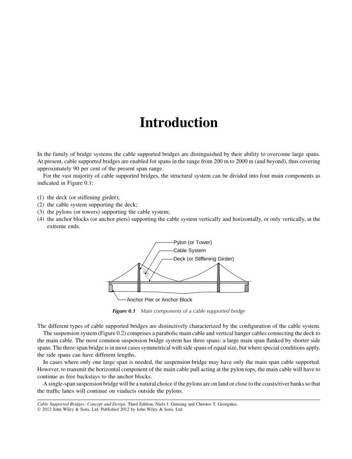
For the vast majority of cable supported bridges, the structural system can be divided into four main components as
indicated in Figure 0.1:
(1) the deck (or stiffening girder);
(2) the cable system supporting the deck;
(3) the pylons (or towers) supporting the cable system;
(4) the anchor blocks (or anchor piers) supporting the cable system vertically and horizontally, or only vertically, at the
extreme ends.
The different types of cable supported bridges are distinctively characterized by the configuration of the cable system.
The suspension system (Figure 0.2) comprises a parabolic main cable and vertical hanger cables connecting the deck to
the main cable. The most common suspension bridge system has three spans: a large main span flanked by shorter side
spans. The three-span bridge is inmost cases symmetrical with side spans of equal size, butwhere special conditions apply,
the side spans can have different lengths.
In cases where only one large span is needed, the suspension bridge may have only the main span cable supported.
However, to transmit the horizontal component of the main cable pull acting at the pylon tops, the main cable will have to
continue as free backstays to the anchor blocks.
A single-span suspension bridgewill be a natural choice if the pylons are on land or close to the coasts/river banks so that
the traffic lanes will continue on viaducts outside the pylons.
Cable Supported Bridges: Concept and Design, Third Edition. Niels J. Gimsing and Christos T. Georgakis.� 2012 John Wiley & Sons, Ltd. Published 2012 by John Wiley & Sons, Ltd.
Pylon (or Tower)
Cable System
Deck (or Stiffening Girder)
Anchor Pier or Anchor Block
Figure 0.1 Main components of a cable supported bridge
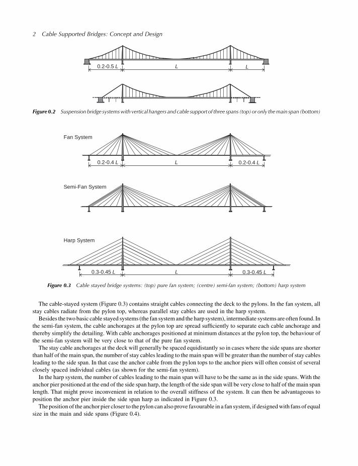
The cable-stayed system (Figure 0.3) contains straight cables connecting the deck to the pylons. In the fan system, all
stay cables radiate from the pylon top, whereas parallel stay cables are used in the harp system.
Besides the twobasic cable stayed systems (the fan systemand the harp system), intermediate systems are often found. In
the semi-fan system, the cable anchorages at the pylon top are spread sufficiently to separate each cable anchorage and
thereby simplify the detailing. With cable anchorages positioned at minimum distances at the pylon top, the behaviour of
the semi-fan system will be very close to that of the pure fan system.
The stay cable anchorages at the deck will generally be spaced equidistantly so in cases where the side spans are shorter
than half of the main span, the number of stay cables leading to themain spanwill be greater than the number of stay cables
leading to the side span. In that case the anchor cable from the pylon tops to the anchor piers will often consist of several
closely spaced individual cables (as shown for the semi-fan system).
In the harp system, the number of cables leading to the main span will have to be the same as in the side spans. With the
anchor pier positioned at the end of the side span harp, the length of the side span will be very close to half of the main span
length. That might prove inconvenient in relation to the overall stiffness of the system. It can then be advantageous to
position the anchor pier inside the side span harp as indicated in Figure 0.3.
The position of the anchor pier closer to the pylon can also prove favourable in a fan system, if designedwith fans of equal
size in the main and side spans (Figure 0.4).
Fan System
Semi-Fan System
Harp System
L0.2-0.4 L 0.2-0.4 L
0.3-0.45 LL0.3-0.45 L
Figure 0.3 Cable stayed bridge systems: (top) pure fan system; (centre) semi-fan system; (bottom) harp system
L0.2-0.5 L L
Figure 0.2 Suspensionbridge systemswith vertical hangers and cable support of three spans (top) or only themain span (bottom)
2 Cable Supported Bridges: Concept and Design
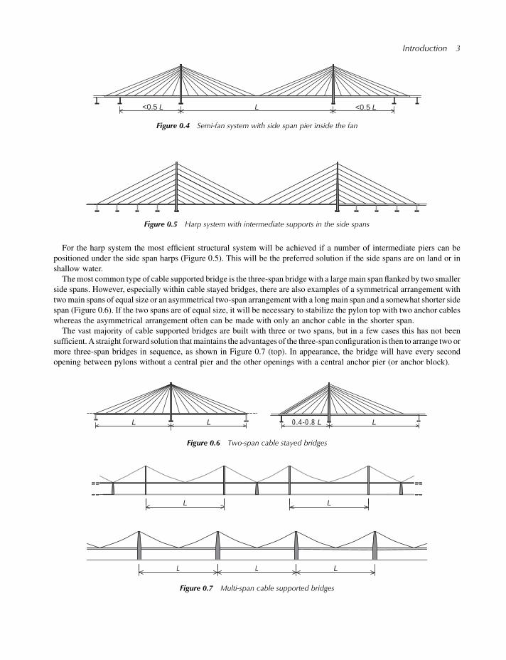
For the harp system the most efficient structural system will be achieved if a number of intermediate piers can be
positioned under the side span harps (Figure 0.5). This will be the preferred solution if the side spans are on land or in
shallow water.
Themost common type of cable supported bridge is the three-span bridgewith a large main span flanked by two smaller
side spans. However, especially within cable stayed bridges, there are also examples of a symmetrical arrangement with
twomain spans of equal size or an asymmetrical two-span arrangement with a longmain span and a somewhat shorter side
span (Figure 0.6). If the two spans are of equal size, it will be necessary to stabilize the pylon top with two anchor cables
whereas the asymmetrical arrangement often can be made with only an anchor cable in the shorter span.
The vast majority of cable supported bridges are built with three or two spans, but in a few cases this has not been
sufficient.A straight forward solution thatmaintains the advantages of the three-span configuration is then to arrange two or
more three-span bridges in sequence, as shown in Figure 0.7 (top). In appearance, the bridge will have every second
opening between pylons without a central pier and the other openings with a central anchor pier (or anchor block).
LL L0.4-0.8 L
Figure 0.6 Two-span cable stayed bridges
<0.5 LL<0.5 L
Figure 0.4 Semi-fan system with side span pier inside the fan
Figure 0.5 Harp system with intermediate supports in the side spans
LL
L L L
Figure 0.7 Multi-span cable supported bridges
Introduction 3
A true multi-span cable supported bridge will consist of a number of main spans back-to-back as shown in
Figure 0.7 (bottom).
In many cases, a true multi-span cable stayed bridge (bottom) will be preferable to a series of three-span bridges (top)
from the point of view of appearance and function. However, from a structural viewpoint, the true multi-span arrangement
presents a number of problems.
Due to the lack of anchor cables leading from vertically fixed points at the deck level to the pylon tops, the pylon must
possess a considerable flexural stiffness to be able to withstand (with acceptable horizontal displacement at the top) a
loading condition with traffic load in only one of the two spans adjacent to the pylon. In such a loading condition, the cable
pull from the loaded span will be larger than from the unloaded span so the pylon must be able to withstand the difference
between the horizontal force from the cable system in the loaded span and in the unloaded span.
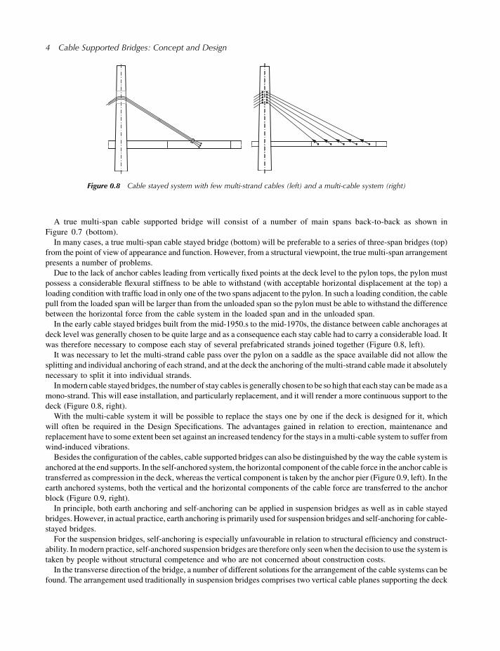
In the early cable stayed bridges built from the mid-1950.s to the mid-1970s, the distance between cable anchorages at
deck level was generally chosen to be quite large and as a consequence each stay cable had to carry a considerable load. It
was therefore necessary to compose each stay of several prefabricated strands joined together (Figure 0.8, left).
It was necessary to let the multi-strand cable pass over the pylon on a saddle as the space available did not allow the
splitting and individual anchoring of each strand, and at the deck the anchoring of themulti-strand cable made it absolutely
necessary to split it into individual strands.
Inmodern cable stayed bridges, the number of stay cables is generally chosen to be so high that each stay can bemade as a
mono-strand. This will ease installation, and particularly replacement, and it will render a more continuous support to the
deck (Figure 0.8, right).
With the multi-cable system it will be possible to replace the stays one by one if the deck is designed for it, which
will often be required in the Design Specifications. The advantages gained in relation to erection, maintenance and
replacement have to some extent been set against an increased tendency for the stays in amulti-cable system to suffer from
wind-induced vibrations.
Besides the configuration of the cables, cable supported bridges can also be distinguished by theway the cable system is
anchored at the end supports. In the self-anchored system, the horizontal component of the cable force in the anchor cable is
transferred as compression in the deck, whereas the vertical component is taken by the anchor pier (Figure 0.9, left). In the
earth anchored systems, both the vertical and the horizontal components of the cable force are transferred to the anchor
block (Figure 0.9, right).
In principle, both earth anchoring and self-anchoring can be applied in suspension bridges as well as in cable stayed
bridges. However, in actual practice, earth anchoring is primarily used for suspension bridges and self-anchoring for cable-
stayed bridges.
For the suspension bridges, self-anchoring is especially unfavourable in relation to structural efficiency and construct-
ability. Inmodern practice, self-anchored suspension bridges are therefore only seenwhen the decision to use the system is
taken by people without structural competence and who are not concerned about construction costs.
In the transverse direction of the bridge, a number of different solutions for the arrangement of the cable systems can be
found. The arrangement used traditionally in suspension bridges comprises two vertical cable planes supporting the deck
Figure 0.8 Cable stayed system with few multi-strand cables (left) and a multi-cable system (right)
4 Cable Supported Bridges: Concept and Design
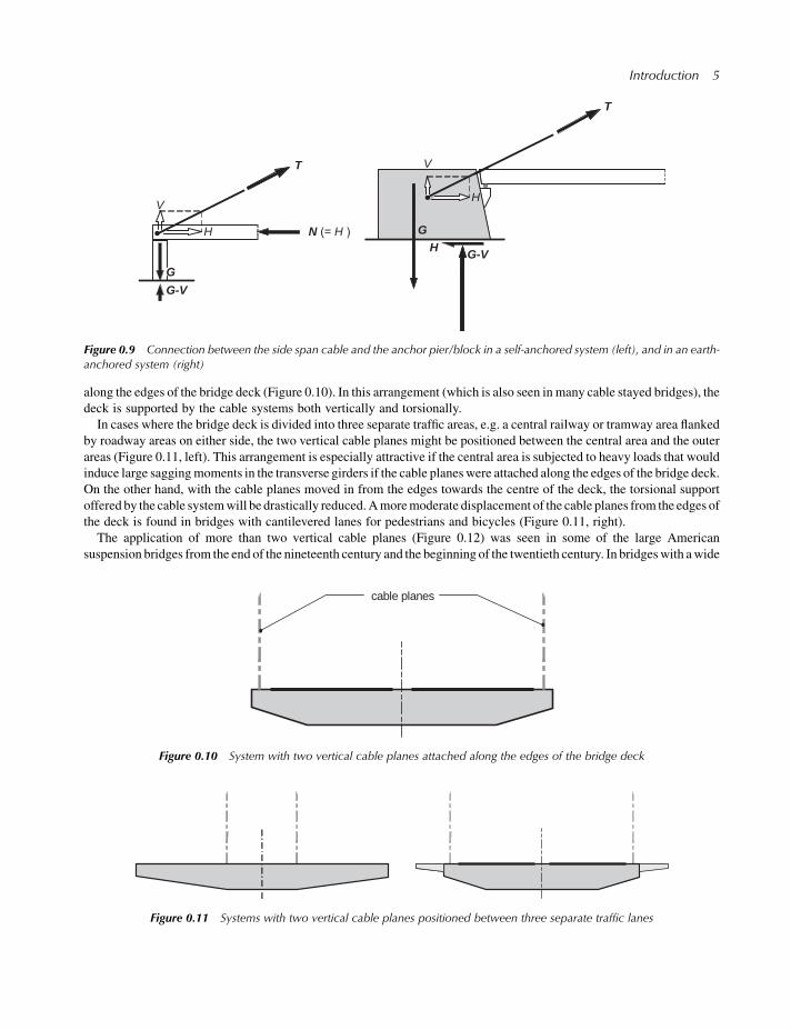
along the edges of the bridge deck (Figure 0.10). In this arrangement (which is also seen in many cable stayed bridges), the
deck is supported by the cable systems both vertically and torsionally.
In cases where the bridge deck is divided into three separate traffic areas, e.g. a central railway or tramway area flanked
by roadway areas on either side, the two vertical cable planes might be positioned between the central area and the outer
areas (Figure 0.11, left). This arrangement is especially attractive if the central area is subjected to heavy loads that would
induce large saggingmoments in the transverse girders if the cable planes were attached along the edges of the bridge deck.
On the other hand, with the cable planes moved in from the edges towards the centre of the deck, the torsional support
offered by the cable systemwill be drastically reduced.Amoremoderate displacement of the cable planes from the edges of
the deck is found in bridges with cantilevered lanes for pedestrians and bicycles (Figure 0.11, right).
The application of more than two vertical cable planes (Figure 0.12) was seen in some of the large American
suspension bridges from the end of the nineteenth century and the beginning of the twentieth century. In bridgeswith awide
cable planes
Figure 0.10 System with two vertical cable planes attached along the edges of the bridge deck
H
V
GH G-V
H
V
GG-V
N H
T
T
Figure 0.9 Connection between the side span cable and the anchor pier/block in a self-anchored system (left), and in an earth-anchored system (right)
Figure 0.11 Systems with two vertical cable planes positioned between three separate traffic lanes
Introduction 5
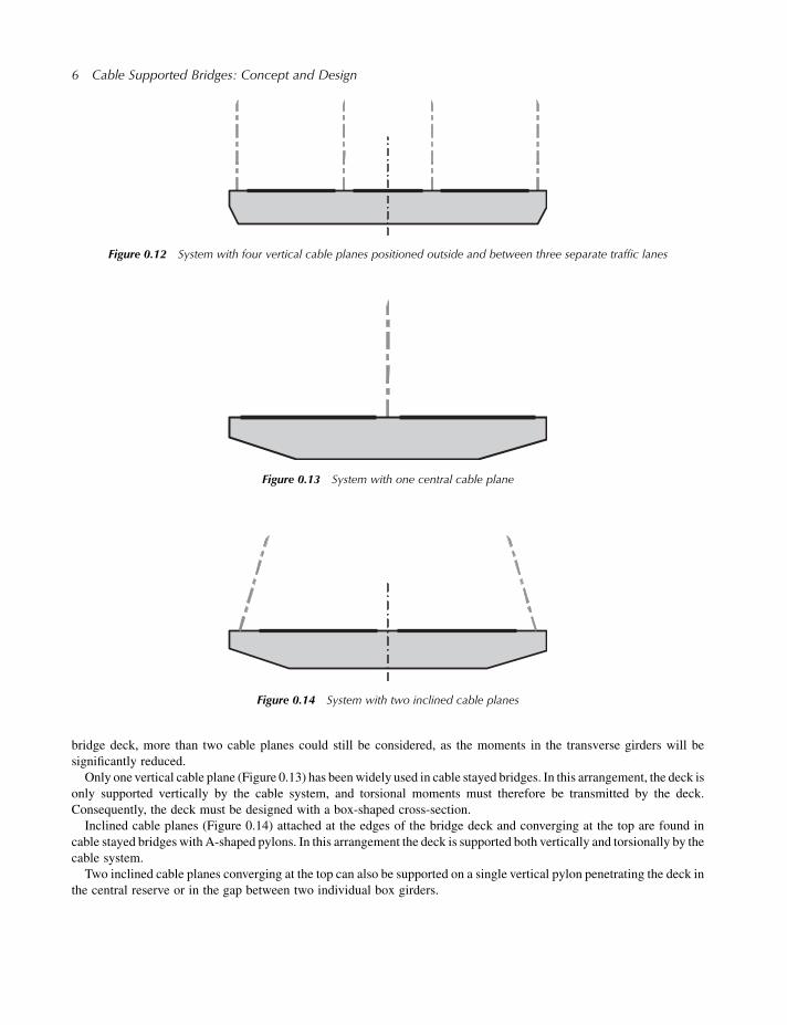
bridge deck, more than two cable planes could still be considered, as the moments in the transverse girders will be
significantly reduced.
Only one vertical cable plane (Figure 0.13) has beenwidely used in cable stayed bridges. In this arrangement, the deck is
only supported vertically by the cable system, and torsional moments must therefore be transmitted by the deck.
Consequently, the deck must be designed with a box-shaped cross-section.
Inclined cable planes (Figure 0.14) attached at the edges of the bridge deck and converging at the top are found in
cable stayed bridges with A-shaped pylons. In this arrangement the deck is supported both vertically and torsionally by the
cable system.
Two inclined cable planes converging at the top can also be supported on a single vertical pylon penetrating the deck in
the central reserve or in the gap between two individual box girders.
Figure 0.13 System with one central cable plane
Figure 0.12 System with four vertical cable planes positioned outside and between three separate traffic lanes
Figure 0.14 System with two inclined cable planes
6 Cable Supported Bridges: Concept and Design
1
Evolution of Cable Supported Bridges
The principle of carrying loads by suspending a rope, chain or cable across an obstacle has been known since ancient times.
However, it was not until 1823 that the first permanent bridge supported by cables composed of drawn iron wires was built
in Geneva by the Frenchman Marc Seguin, one of five brothers who, in the following two decades, built hundreds of
suspension bridges aroundEurope.All of these bridgeswere ofmodest size but theymarked an important step on theway to
the more impressive structures that followed.
The application of thin wires in themain load-carrying elements gave rise to a number of problems especially in relation
to durability, as an efficient method for corrosion protection had not been found at that time. Therefore, some of the leading
engineers preferred to construct suspension bridgeswith themain load-carrying elements, the catenaries, composed of pin-
connected eye-bars forming huge chains.
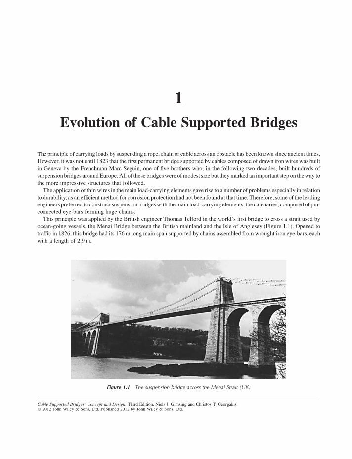
This principle was applied by the British engineer Thomas Telford in the world’s first bridge to cross a strait used by
ocean-going vessels, the Menai Bridge between the British mainland and the Isle of Anglesey (Figure 1.1). Opened to
traffic in 1826, this bridge had its 176m long main span supported by chains assembled from wrought iron eye-bars, each
with a length of 2.9m.
Cable Supported Bridges: Concept and Design, Third Edition. Niels J. Gimsing and Christos T. Georgakis.� 2012 John Wiley & Sons, Ltd. Published 2012 by John Wiley & Sons, Ltd.
Figure 1.1 The suspension bridge across the Menai Strait (UK)
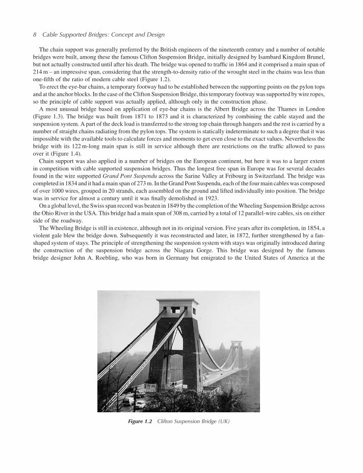
The chain support was generally preferred by the British engineers of the nineteenth century and a number of notable
bridges were built, among these the famous Clifton Suspension Bridge, initially designed by Isambard Kingdom Brunel,
but not actually constructed until after his death. The bridge was opened to traffic in 1864 and it comprised a main span of
214m – an impressive span, considering that the strength-to-density ratio of the wrought steel in the chains was less than
one-fifth of the ratio of modern cable steel (Figure 1.2).
To erect the eye-bar chains, a temporary footway had to be established between the supporting points on the pylon tops
and at the anchor blocks. In the case of theClifton SuspensionBridge, this temporary footwaywas supported bywire ropes,
so the principle of cable support was actually applied, although only in the construction phase.
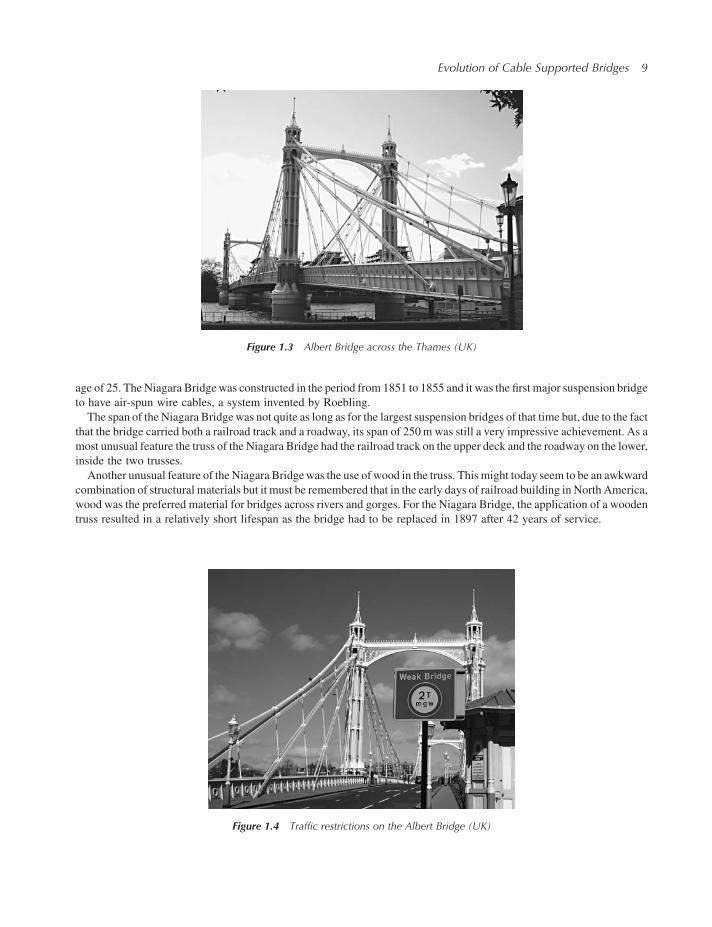
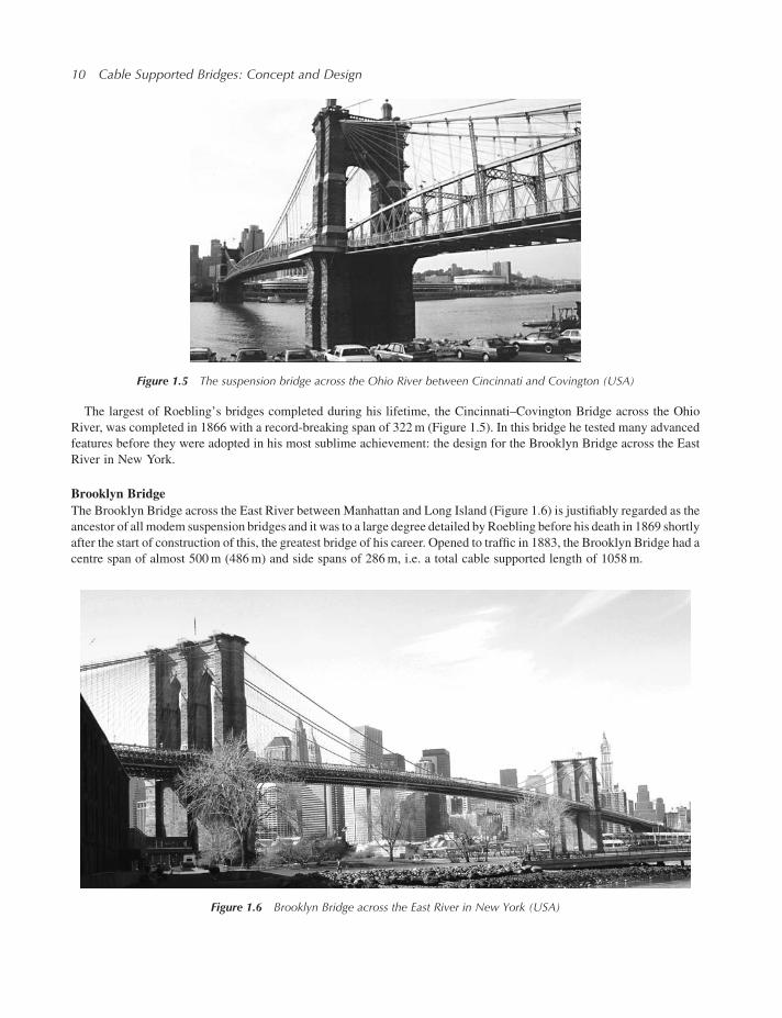
A most unusual bridge based on application of eye-bar chains is the Albert Bridge across the Thames in London
(Figure 1.3). The bridge was built from 1871 to 1873 and it is characterized by combining the cable stayed and the
suspension system. A part of the deck load is transferred to the strong top chain through hangers and the rest is carried by a
number of straight chains radiating from the pylon tops. The system is statically indeterminate to such a degree that it was
impossible with the available tools to calculate forces and moments to get even close to the exact values. Nevertheless the
bridge with its 122m-long main span is still in service although there are restrictions on the traffic allowed to pass
over it (Figure 1.4).
Chain support was also applied in a number of bridges on the European continent, but here it was to a larger extent
in competition with cable supported suspension bridges. Thus the longest free span in Europe was for several decades
found in the wire supported Grand Pont Suspendu across the Sarine Valley at Fribourg in Switzerland. The bridge was
completed in 1834 and it had amain span of 273m. In theGrand Pont Suspendu, each of the fourmain cableswas composed
of over 1000 wires, grouped in 20 strands, each assembled on the ground and lifted individually into position. The bridge
was in service for almost a century until it was finally demolished in 1923.
On a global level, the Swiss span recordwas beaten in 1849 by the completion of theWheeling SuspensionBridge across
the Ohio River in the USA. This bridge had a main span of 308m, carried by a total of 12 parallel-wire cables, six on either
side of the roadway.
TheWheeling Bridge is still in existence, although not in its original version. Five years after its completion, in 1854, a
violent gale blew the bridge down. Subsequently it was reconstructed and later, in 1872, further strengthened by a fan-
shaped system of stays. The principle of strengthening the suspension system with stays was originally introduced during
the construction of the suspension bridge across the Niagara Gorge. This bridge was designed by the famous
bridge designer John A. Roebling, who was born in Germany but emigrated to the United States of America at the
Figure 1.2 Clifton Suspension Bridge (UK)
8 Cable Supported Bridges: Concept and Design
age of 25. The Niagara Bridgewas constructed in the period from 1851 to 1855 and it was the first major suspension bridge
to have air-spun wire cables, a system invented by Roebling.
The span of the Niagara Bridgewas not quite as long as for the largest suspension bridges of that time but, due to the fact
that the bridge carried both a railroad track and a roadway, its span of 250m was still a very impressive achievement. As a
most unusual feature the truss of the Niagara Bridge had the railroad track on the upper deck and the roadway on the lower,
inside the two trusses.
Another unusual feature of the Niagara Bridgewas the use of wood in the truss. Thismight today seem to be an awkward
combination of structural materials but it must be remembered that in the early days of railroad building in North America,
wood was the preferred material for bridges across rivers and gorges. For the Niagara Bridge, the application of a wooden
truss resulted in a relatively short lifespan as the bridge had to be replaced in 1897 after 42 years of service.
Figure 1.3 Albert Bridge across the Thames (UK)
Figure 1.4 Traffic restrictions on the Albert Bridge (UK)
Evolution of Cable Supported Bridges 9
The largest of Roebling’s bridges completed during his lifetime, the Cincinnati–Covington Bridge across the Ohio
River, was completed in 1866 with a record-breaking span of 322m (Figure 1.5). In this bridge he tested many advanced
features before they were adopted in his most sublime achievement: the design for the Brooklyn Bridge across the East
River in New York.
Brooklyn Bridge
The Brooklyn Bridge across the East River between Manhattan and Long Island (Figure 1.6) is justifiably regarded as the
ancestor of all modem suspension bridges and it was to a large degree detailed byRoebling before his death in 1869 shortly
after the start of construction of this, the greatest bridge of his career. Opened to traffic in 1883, the Brooklyn Bridge had a
centre span of almost 500m (486m) and side spans of 286m, i.e. a total cable supported length of 1058m.
Figure 1.5 The suspension bridge across the Ohio River between Cincinnati and Covington (USA)
Figure 1.6 Brooklyn Bridge across the East River in New York (USA)
10 Cable Supported Bridges: Concept and Design
Based on his experience during design and construction of several suspension bridges, and through his investigations
into accidents such as the collapse of theWheeling Bridge in 1854, Roebling had acquired a profound understanding of the
aerodynamic problem. This is clearly indicated in his own description of the Brooklyn Bridge concept:
But my system of construction differs radically from that formerly practised, and I have planned the East River
Bridge [as the Brooklyn Bridge was initially called] with a special view to fully meet the destructive forces of a
severe gale. It is the same reason that, in my calculation of the requisite supporting strength so large a proportion has
been assigned to the stays in place of cables.
This description proves that Roebling knew very well that a cable stayed system is stiffer than the suspension system, and
the fact that the stays of theBrooklynBridge carry a considerable part of the load can be detected by the configuration of the
main cable having a smaller curvature in the regions where the stays carry a part of the permanent load than in the central
region, where all load is carried exclusively by the main cable.
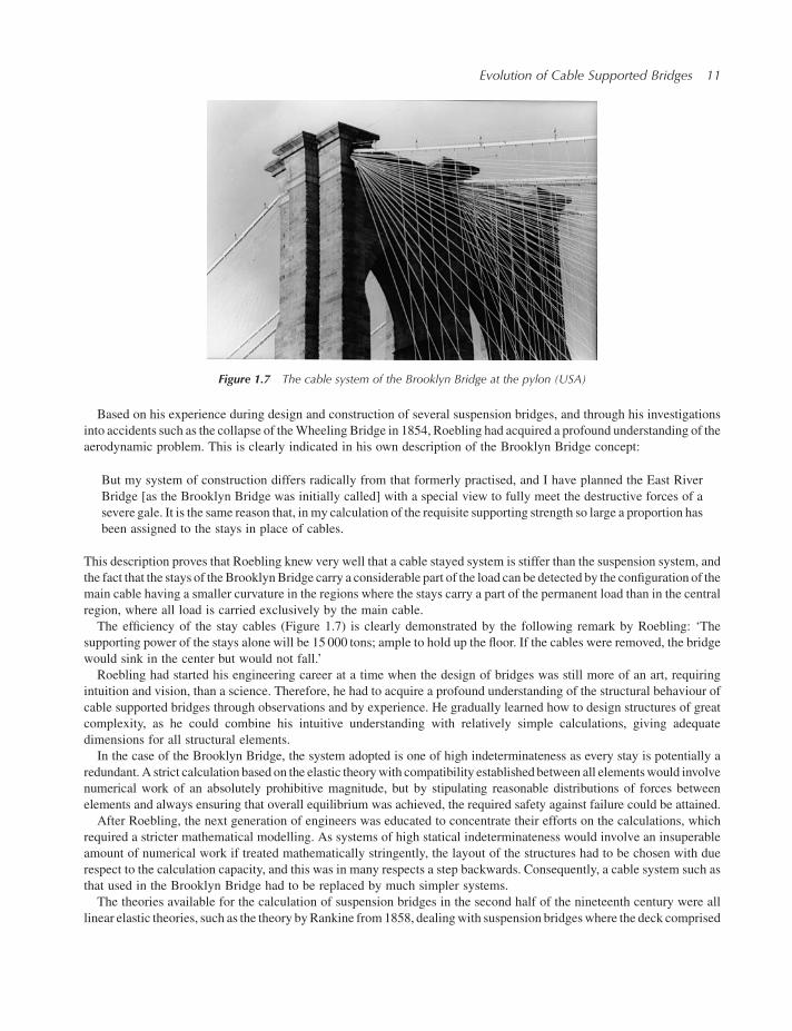
The efficiency of the stay cables (Figure 1.7) is clearly demonstrated by the following remark by Roebling: ‘The
supporting power of the stays alone will be 15 000 tons; ample to hold up the floor. If the cables were removed, the bridge
would sink in the center but would not fall.’
Roebling had started his engineering career at a time when the design of bridges was still more of an art, requiring
intuition and vision, than a science. Therefore, he had to acquire a profound understanding of the structural behaviour of
cable supported bridges through observations and by experience. He gradually learned how to design structures of great
complexity, as he could combine his intuitive understanding with relatively simple calculations, giving adequate
dimensions for all structural elements.
In the case of the Brooklyn Bridge, the system adopted is one of high indeterminateness as every stay is potentially a
redundant. A strict calculation based on the elastic theorywith compatibility established between all elementswould involve
numerical work of an absolutely prohibitive magnitude, but by stipulating reasonable distributions of forces between
elements and always ensuring that overall equilibrium was achieved, the required safety against failure could be attained.
After Roebling, the next generation of engineers was educated to concentrate their efforts on the calculations, which
required a stricter mathematical modelling. As systems of high statical indeterminateness would involve an insuperable
amount of numerical work if treated mathematically stringently, the layout of the structures had to be chosen with due
respect to the calculation capacity, and this was in many respects a step backwards. Consequently, a cable system such as
that used in the Brooklyn Bridge had to be replaced by much simpler systems.
The theories available for the calculation of suspension bridges in the second half of the nineteenth century were all
linear elastic theories, such as the theory byRankine from1858, dealingwith suspension bridgeswhere the deck comprised
Figure 1.7 The cable system of the Brooklyn Bridge at the pylon (USA)
Evolution of Cable Supported Bridges 11
two- and three-hinged girders. The theory was the first to take into account rationally the interaction between the cable and
the deck. Later, in 1886, the linear elastic theory was further developed by Maurice Levy in his paper, ‘M�emoires sur le
calcul des ponts suspendus rigides’.
Williamsburg Bridge
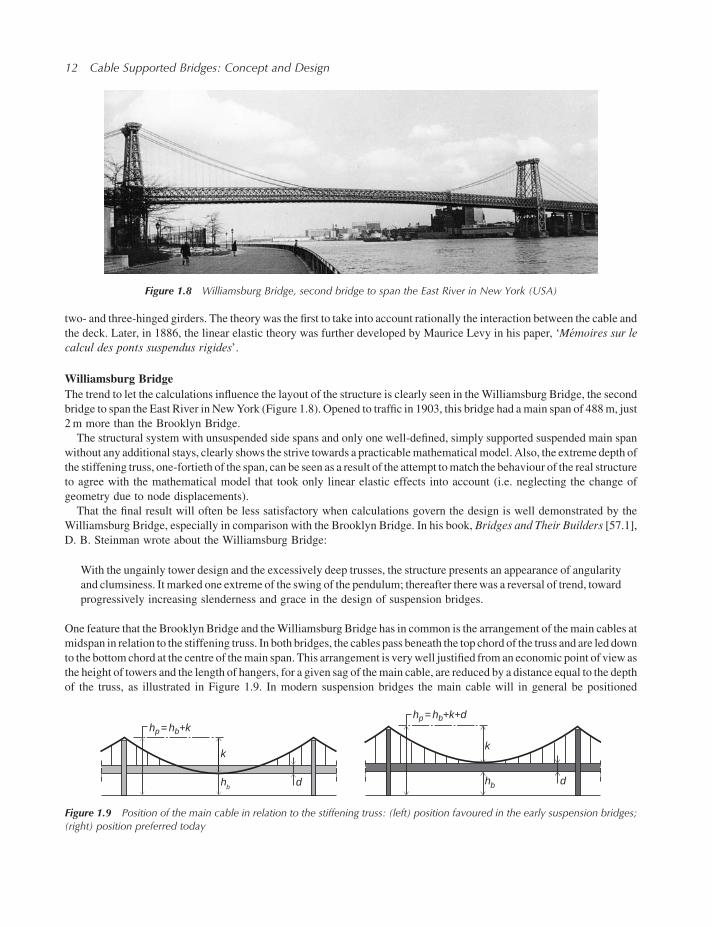
The trend to let the calculations influence the layout of the structure is clearly seen in theWilliamsburg Bridge, the second
bridge to span the East River in NewYork (Figure 1.8). Opened to traffic in 1903, this bridge had amain span of 488m, just
2m more than the Brooklyn Bridge.
The structural system with unsuspended side spans and only one well-defined, simply supported suspended main span
without any additional stays, clearly shows the strive towards a practicablemathematicalmodel. Also, the extreme depth of
the stiffening truss, one-fortieth of the span, can be seen as a result of the attempt tomatch the behaviour of the real structure
to agree with the mathematical model that took only linear elastic effects into account (i.e. neglecting the change of
geometry due to node displacements).
That the final result will often be less satisfactory when calculations govern the design is well demonstrated by the
Williamsburg Bridge, especially in comparison with the Brooklyn Bridge. In his book, Bridges and Their Builders [57.1],
D. B. Steinman wrote about the Williamsburg Bridge:
With the ungainly tower design and the excessively deep trusses, the structure presents an appearance of angularity
and clumsiness. It marked one extreme of the swing of the pendulum; thereafter therewas a reversal of trend, toward
progressively increasing slenderness and grace in the design of suspension bridges.
One feature that the Brooklyn Bridge and theWilliamsburg Bridge has in common is the arrangement of themain cables at
midspan in relation to the stiffening truss. In both bridges, the cables pass beneath the top chord of the truss and are led down
to the bottomchord at the centre of themain span. This arrangement is verywell justified froman economic point of view as
the height of towers and the length of hangers, for a given sag of themain cable, are reduced by a distance equal to the depth
of the truss, as illustrated in Figure 1.9. In modern suspension bridges the main cable will in general be positioned
Figure 1.8 Williamsburg Bridge, second bridge to span the East River in New York (USA)
hp= hb+khp= hb+k+d
k
hb d
k
hb d
Figure 1.9 Position of the main cable in relation to the stiffening truss: (left) position favoured in the early suspension bridges;(right) position preferred today
12 Cable Supported Bridges: Concept and Design
entirely above the deck, which undoubtedly is preferable with regards to the appearance, as the cable curve is more easily
perceived.Also, inmodern bridgeswith slender decks, the savingswould be smaller than in theWilliamsburgBridgewhere
the truss depth corresponds to as much as 25% of the main cable sag.
Manhattan Bridge
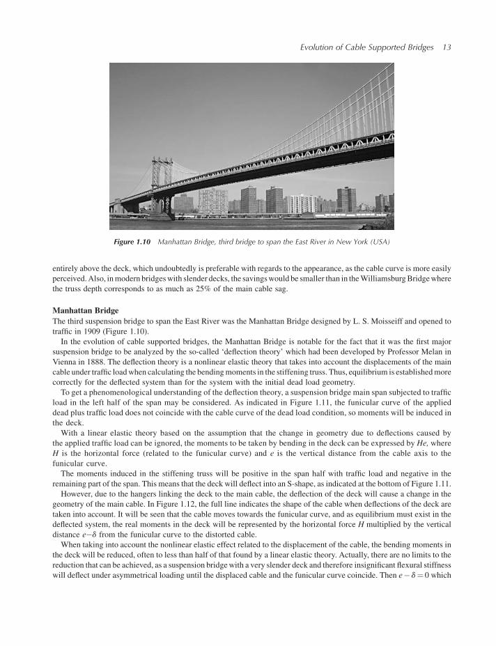
The third suspension bridge to span the East River was the Manhattan Bridge designed by L. S. Moisseiff and opened to
traffic in 1909 (Figure 1.10).
In the evolution of cable supported bridges, the Manhattan Bridge is notable for the fact that it was the first major
suspension bridge to be analyzed by the so-called ‘deflection theory’ which had been developed by Professor Melan in
Vienna in 1888. The deflection theory is a nonlinear elastic theory that takes into account the displacements of the main
cable under traffic loadwhen calculating the bendingmoments in the stiffening truss. Thus, equilibrium is establishedmore
correctly for the deflected system than for the system with the initial dead load geometry.
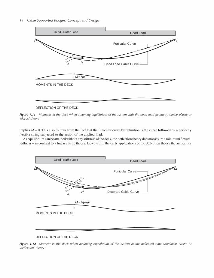
To get a phenomenological understanding of the deflection theory, a suspension bridge main span subjected to traffic
load in the left half of the span may be considered. As indicated in Figure 1.11, the funicular curve of the applied
dead plus traffic load does not coincide with the cable curve of the dead load condition, so moments will be induced in
the deck.
With a linear elastic theory based on the assumption that the change in geometry due to deflections caused by
the applied traffic load can be ignored, the moments to be taken by bending in the deck can be expressed by He, where
H is the horizontal force (related to the funicular curve) and e is the vertical distance from the cable axis to the
funicular curve.
The moments induced in the stiffening truss will be positive in the span half with traffic load and negative in the
remaining part of the span. This means that the deck will deflect into an S-shape, as indicated at the bottom of Figure 1.11.
However, due to the hangers linking the deck to the main cable, the deflection of the deck will cause a change in the
geometry of the main cable. In Figure 1.12, the full line indicates the shape of the cable when deflections of the deck are
taken into account. It will be seen that the cable moves towards the funicular curve, and as equilibrium must exist in the
deflected system, the real moments in the deck will be represented by the horizontal force H multiplied by the vertical
distance e�d from the funicular curve to the distorted cable.
When taking into account the nonlinear elastic effect related to the displacement of the cable, the bending moments in
the deck will be reduced, often to less than half of that found by a linear elastic theory. Actually, there are no limits to the
reduction that can be achieved, as a suspension bridgewith a very slender deck and therefore insignificant flexural stiffness
will deflect under asymmetrical loading until the displaced cable and the funicular curve coincide. Then e� d¼ 0 which
Figure 1.10 Manhattan Bridge, third bridge to span the East River in New York (USA)
Evolution of Cable Supported Bridges 13
implies M¼ 0. This also follows from the fact that the funicular curve by definition is the curve followed by a perfectly
flexible string subjected to the action of the applied load.
As equilibrium can be attainedwithout any stiffness of the deck, the deflection theory does not assure aminimumflexural
stiffness – in contrast to a linear elastic theory. However, in the early applications of the deflection theory the authorities
Dead Load
Funicular Curve
Dead Load Cable CurveHe
M = He
MOMENTS IN THE DECK
DEFLECTION OF THE DECK
Figure 1.11 Moments in the deck when assuming equilibrium of the system with the dead load geometry (linear elastic or‘elastic’ theory)
Dead Load
Funicular Curve
Distorted Cable CurveHe
M = H(e-δ)
MOMENTS IN THE DECK
DEFLECTION OF THE DECK
δ
Figure 1.12 Moment in the deck when assuming equilibrium of the system in the deflected state (nonlinear elastic or‘deflection’ theory)
14 Cable Supported Bridges: Concept and Design
specified a minimum depth of the stiffening truss in the interval from one-sixtieth to one-ninetieth of the span length and
thereby actually introduced a lower limit for the bending stiffness.
At the timewhen the deflection theory was introduced, the calculation capacity was limited so the solution procedure for
the nonlinear differential equation was complicated and tedious for the practising engineer. Consequently, simplifications
had to be introduced in the form of charts, tables, and correction curves by which the results of the simpler, linear elastic
theory could be corrected to approximate those of the deflection theory.
Besides the new analytical approach, theManhattanBridge also introduced several new construction techniques, such as
pylon erection by vertically travelling derrick cranes, and cable wrapping by a self-propelling machine.
After the opening of the Manhattan Bridge, only modest progress was made in the design of cable supported bridges
for a period of more than 20 years, although some bridges with spans slightly exceeding the span of the Manhattan Bridge
were constructed.
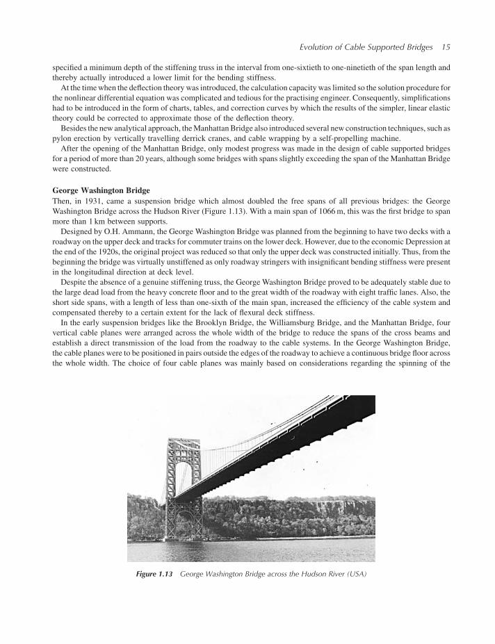
George Washington Bridge
Then, in 1931, came a suspension bridge which almost doubled the free spans of all previous bridges: the George
Washington Bridge across the Hudson River (Figure 1.13). With a main span of 1066m, this was the first bridge to span
more than 1 km between supports.
Designed by O.H. Ammann, the George Washington Bridge was planned from the beginning to have two decks with a
roadway on the upper deck and tracks for commuter trains on the lower deck. However, due to the economic Depression at
the end of the 1920s, the original project was reduced so that only the upper deck was constructed initially. Thus, from the
beginning the bridge was virtually unstiffened as only roadway stringers with insignificant bending stiffness were present
in the longitudinal direction at deck level.
Despite the absence of a genuine stiffening truss, the George Washington Bridge proved to be adequately stable due to
the large dead load from the heavy concrete floor and to the great width of the roadway with eight traffic lanes. Also, the
short side spans, with a length of less than one-sixth of the main span, increased the efficiency of the cable system and
compensated thereby to a certain extent for the lack of flexural deck stiffness.
In the early suspension bridges like the Brooklyn Bridge, the Williamsburg Bridge, and the Manhattan Bridge, four
vertical cable planes were arranged across the whole width of the bridge to reduce the spans of the cross beams and
establish a direct transmission of the load from the roadway to the cable systems. In the George Washington Bridge,
the cable planes were to be positioned in pairs outside the edges of the roadway to achieve a continuous bridge floor across
the whole width. The choice of four cable planes was mainly based on considerations regarding the spinning of the
Figure 1.13 George Washington Bridge across the Hudson River (USA)
Evolution of Cable Supported Bridges 15
cables, asworking on four cables instead of twowould speed up the erection considerably. Thiswas especially important as
very large cable cross sections were required to carry the load from the wide bridge decks.
The cable system, the anchor blocks and the pylons were designed for the full double-deck structure and they were not
reduced in size when the lower deck was initially omitted.
The three-dimensional deflection theory
An interesting development in the process of analyzing suspension bridges appeared in 1932 when L. S. Moisseiff and
F. Lienhard presented a theory for the calculation of suspension bridges under lateral load [32.1]. Actually the theory can be
regarded as an extension of the nonlinear elastic deflection theory (that had so far only been developed for vertical in-plane
loading) to cover horizontal forces also. Thus, the inclination of the cable planes caused by the lateral deflection of the deck
could now be taken into account when calculating the moments and shear forces in the horizontal wind girder.
The new theory led to a substantial reduction of the lateral load to be carried by the deck itself, and the reduction became
more and more pronounced with increasing slenderness of the wind girder. It would even be possible to create lateral
equilibrium without any wind girder at all.
It earlier was mentioned how the two-dimensional deflection theory developed byMelan had removed the lower bound
for the flexural stiffness of the deck in the vertical direction, and now the extension of the deflection theory to cover the
three-dimensional behaviour implied that a lower bound for the lateral flexural stiffness also disappeared.
In the hands of engineers deprived of the intuitive understanding found in the previous century, and now trained to trust
blindly the results of the calculations, these analytical achievements could, and should, lead to serious mistakes.
The 1930s became a decade of great achievements in the field of cable supported bridges in theUnited States: theGeorge
Washington Bridge was followed by such impressive structures as the San Francisco–Oakland Bay Bridge, designed by
Moisseiff, and the Golden Gate Bridge, designed by J. B. Strauss.
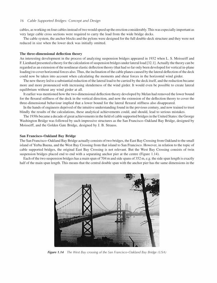
San Francisco–Oakland Bay Bridge
The San Francisco–Oakland Bay Bridge actually consists of two bridges, the East Bay Crossing fromOakland to the small
island of Yerba Buena, and the West Bay Crossing from that island to San Francisco. However, in relation to the topic of
cable supported bridges, the original East Bay Crossing is not relevant. But the West Bay Crossing consists of twin
suspension bridges placed end to end with a separating anchor pier at the centre (Figure 1.14).
Each of the two suspension bridges has amain span of 704m and side spans of 352m, e.g. the side span length is exactly
half of the main span length. This means that the central double span with the anchor pier has the same dimensions in the
Figure 1.14 The West Bay crossing of the San Francisco–Oakland Bay Bridge (USA)
16 Cable Supported Bridges: Concept and Design
superstructure as the adjoining main spans. For this reason, the heavy anchor pier might at first seem unnecessary: why an
anchor pier in the central span when the adjoining spans do not need any?
Considering at first only a constant load such as dead load, the anchor pier is actually inactive as the horizontal
component of the cable force is constant from end anchorage to end anchorage. But in the case of traffic load applied to only
one of the two main spans, the horizontal force in that part of the double bridge will be increased. The anchor pier must
therefore be able to resist the difference between the horizontal force from the span with dead load plus traffic load and the
horizontal force from the span with dead load only.
During the preliminary investigations, solutions without the central anchor pier were studied [33.1] but none of these
more unconventional solutions reached the stage of detailed planning (Figures 3.136 and 3.166).
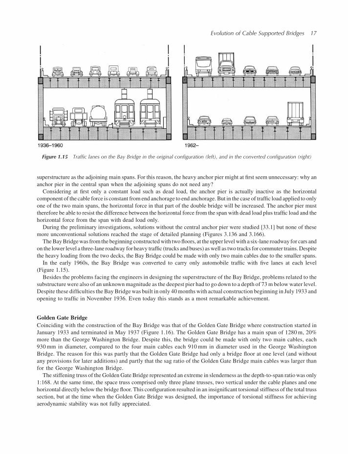
TheBayBridgewas from the beginning constructedwith twofloors, at the upper levelwith a six-lane roadway for cars and
on the lower level a three-lane roadway for heavy traffic (trucks and buses) aswell as two tracks for commuter trains. Despite
the heavy loading from the two decks, the Bay Bridge could be made with only two main cables due to the smaller spans.
In the early 1960s, the Bay Bridge was converted to carry only automobile traffic with five lanes at each level
(Figure 1.15).
Besides the problems facing the engineers in designing the superstructure of the Bay Bridge, problems related to the
substructurewere also of an unknownmagnitude as the deepest pier had to go down to a depth of 73m belowwater level.
Despite these difficulties the BayBridgewas built in only 40months with actual construction beginning in July 1933 and
opening to traffic in November 1936. Even today this stands as a most remarkable achievement.
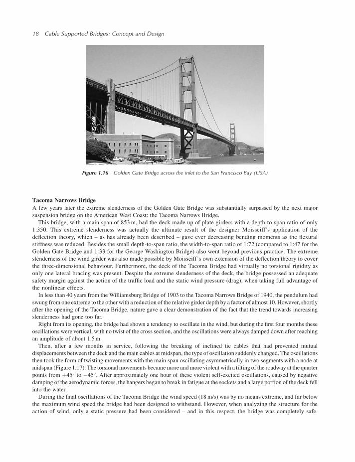
Golden Gate Bridge
Coinciding with the construction of the Bay Bridge was that of the Golden Gate Bridge where construction started in
January 1933 and terminated in May 1937 (Figure 1.16). The Golden Gate Bridge has a main span of 1280m, 20%
more than the George Washington Bridge. Despite this, the bridge could be made with only two main cables, each
930mm in diameter, compared to the four main cables each 910mm in diameter used in the George Washington
Bridge. The reason for this was partly that the Golden Gate Bridge had only a bridge floor at one level (and without
any provisions for later additions) and partly that the sag ratio of the Golden Gate Bridge main cables was larger than
for the George Washington Bridge.
The stiffening truss of the Golden Gate Bridge represented an extreme in slenderness as the depth-to-span ratiowas only
1:168. At the same time, the space truss comprised only three plane trusses, two vertical under the cable planes and one
horizontal directly below the bridge floor. This configuration resulted in an insignificant torsional stiffness of the total truss
section, but at the time when the Golden Gate Bridge was designed, the importance of torsional stiffness for achieving
aerodynamic stability was not fully appreciated.
Figure 1.15 Traffic lanes on the Bay Bridge in the original configuration (left), and in the converted configuration (right)
Evolution of Cable Supported Bridges 17
Tacoma Narrows Bridge
A few years later the extreme slenderness of the Golden Gate Bridge was substantially surpassed by the next major
suspension bridge on the American West Coast: the Tacoma Narrows Bridge.
This bridge, with a main span of 853m, had the deck made up of plate girders with a depth-to-span ratio of only
1:350. This extreme slenderness was actually the ultimate result of the designer Moisseiff’s application of the
deflection theory, which – as has already been described – gave ever decreasing bending moments as the flexural
stiffness was reduced. Besides the small depth-to-span ratio, the width-to-span ratio of 1:72 (compared to 1:47 for the
Golden Gate Bridge and 1:33 for the George Washington Bridge) also went beyond previous practice. The extreme
slenderness of the wind girder was also made possible by Moisseiff’s own extension of the deflection theory to cover
the three-dimensional behaviour. Furthermore, the deck of the Tacoma Bridge had virtually no torsional rigidity as
only one lateral bracing was present. Despite the extreme slenderness of the deck, the bridge possessed an adequate
safety margin against the action of the traffic load and the static wind pressure (drag), when taking full advantage of
the nonlinear effects.
In less than 40 years from the Williamsburg Bridge of 1903 to the Tacoma Narrows Bridge of 1940, the pendulum had
swung from one extreme to the other with a reduction of the relative girder depth by a factor of almost 10. However, shortly
after the opening of the Tacoma Bridge, nature gave a clear demonstration of the fact that the trend towards increasing
slenderness had gone too far.
Right from its opening, the bridge had shown a tendency to oscillate in the wind, but during the first four months these
oscillations were vertical, with no twist of the cross section, and the oscillations were always damped down after reaching
an amplitude of about 1.5m.
Then, after a few months in service, following the breaking of inclined tie cables that had prevented mutual
displacements between the deck and themain cables at midspan, the type of oscillation suddenly changed. The oscillations
then took the form of twisting movements with the main span oscillating asymmetrically in two segments with a node at
midspan (Figure 1.17). The torsional movements becamemore andmore violent with a tilting of the roadway at the quarter
points from þ45� to �45�. After approximately one hour of these violent self-excited oscillations, caused by negative
damping of the aerodynamic forces, the hangers began to break in fatigue at the sockets and a large portion of the deck fell
into the water.
During the final oscillations of the Tacoma Bridge the wind speed (18m/s) was by no means extreme, and far below
the maximum wind speed the bridge had been designed to withstand. However, when analyzing the structure for the
action of wind, only a static pressure had been considered – and in this respect, the bridge was completely safe.
Figure 1.16 Golden Gate Bridge across the inlet to the San Francisco Bay (USA)
18 Cable Supported Bridges: Concept and Design