Cable + Connectivity Solutions Control Solutions Ethernet ...

Cable ManagementSolutions for
Rack Systems
E N C L O S E D M O U N T I N G S Y S T E M SWHITE PAPER
www.chatsworth.com
©2011 Chatsworth Products, Inc. All rights reserved. CPI, CPI Passive Cooling, MegaFrame, Saf-T-Grip, Seismic Frame,SlimFrame, TeraFrame, Cube-iT Plus, Evolution, OnTrac, and QuadraRack are federally registered trademarks of Chatsworth
Products, Inc. GlobalFrame, Simply Efficient and Velocity are trademarks of Chatsworth Products, Inc. All other trademarks belong to their respective companies. Rev.5 02/11 MKT-60020-241
C A B L E M A N A G E M E N T S O L U T I O N S F O R R A C K S Y S T E M SWHITE PAPER
www.chatsworth.com

Cable Management Solutions for Rack Systems
2
Summary
The care given to communications cable during installation and use is the primary factor in maintaining high circuit performance.Industry standards recognize this fact and recommend installation and management practices that will minimize changes in thephysical properties of cable.
Chatsworth Products, Inc. (CPI) Cable Management Solutions support and protect cables to help maintain cable performance. Thisguide will help you understand how to specify the right Cable Management Solution for CPI Rack Systems including freestandingtwo-post and four-post racks.
Cable Performance
Cable performance is dependant on the physical properties of the cable, and therefore, circuit performance is directly related tothe care given to cable during installation and use. For example, copper 4-pair UTP cable relies on the size (cross-section) of theindividual conductors, the twist rates of these conductors and the relative proximities of the individual cable pairs to create a givencircuit performance over a specific distance. Also, each cable pair is twisted at a different rate - meaning the length of each pairgroup is different.
Whenever cable changes direction, the bend in the cable (especially a sharp bend) has potential to change the electricalproperties of the cable by changing the size, twist rate, relative proximities or lengths of the individual conductors. Tight bundlingof the cable or improper support of cable that deforms, stretches or adds tension to the cable can negatively affect circuitperformance. There are similar concerns with fiber.

3
Cable Management Solutions for Rack Systems
The Standards
Network speeds and bandwidth requirements are always increasing. To get the most out of the physical layer, communication systemsdesigners have developed network protocols that transmit information as multiple data packets over multiple pairs of cable in a fullduplex arrangement.
Industry standards provide guidelines that define which cables and connectors are appropriate to support each type of network andsuggest methods for maintaining high levels of cable performance, which includes room layout and the importance of cablemanagement.
The Commercial Building Telecommunications Pathways and Spaces Standard [ANSI/TIA/EIA-569B] suggest size, layout andprovisioning for planning Telecommunications Rooms based on the number of users and floor space being served.
The Commercial Building Telecommunications Cabling Standard [ANSI/TIA/EIA-568B] defines specific types of cables that can be usedwithin the network, maximum distances for these cables at each point-to-point within the network and minimum performancerequirements for testing the installed cables as 'standards-compliant'.
Cable Management Solutions
Use cable management solutions to help maintain smooth turns in cables and to minimize negative effects on circuit performance.Generally accepted minimum bend radius for cable transitions are listed below. Refer to the cable manufacturer’s installationguidelines for specific requirements.
100W CablingBend Radius, 4-pair UTP, no load, 4X cable diameterBend Radius, 4-pair ScTP, no load, 8X cable diameterBend Radius, Multi-pair UTP (i.e., 25 pair, etc), no load, 10X cable diameter
Fiber (2- or 4-fiber optical cables)Bend Radius, no load, 1” (25 mm)Bend Radius, under pulling load tension, 2” (50 mm)
It is important to note that bend radius requirements apply to patch cords as well as premise cable because circuit testing includes allcomponents of the channel.
4
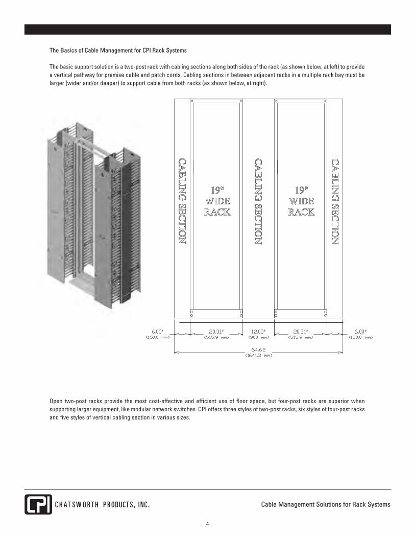
The Basics of Cable Management for CPI Rack Systems
The basic support solution is a two-post rack with cabling sections along both sides of the rack (as shown below, at left) to providea vertical pathway for premise cable and patch cords. Cabling sections in between adjacent racks in a multiple rack bay must belarger (wider and/or deeper) to support cable from both racks (as shown below, at right).
Open two-post racks provide the most cost-effective and efficient use of floor space, but four-post racks are superior whensupporting larger equipment, like modular network switches. CPI offers three styles of two-post racks, six styles of four-post racksand five styles of vertical cabling section in various sizes.
Cable Management Solutions for Rack Systems

Cable Management Solutions for Rack Systems
5
Use cable runway or cable tray to create a pathway for premise cables through the room. Premise cables typically enter thecabling sections from overhead cable runway (ladder rack) or cable tray. Be sure to provide radius drops where cable enters orexits the overhead pathway (as shown below). Also, elevate cable runway 3" to 6" (80 mm to 150 mm) above racks to get the fullbenefit of the radius drop.
Cable runway or cable tray can be supported from the tops of racks with elevation kits or from the ceiling with threaded rods.Cable runway or cable tray can also be divided to allow cable segregation by media or use/application and tiered to increasecapacity.
Radius Drop
Elevation Kit
CenterSupport Kit

Cable Management Solutions for Rack Systems
6
Use jumper trays and horizontal managers on the racks in between patch panels and network switches (as shown below) to guidepatch cords between connections. Use cable spools inside the cabling sections to control patch cord slack. Loosely bundle cableswith CPI’s Saf-T-Grip® Cable Management Straps.
Jumper Tray
UniversalHorizontal CableManager
Cable Spool
Saf-T-GripCableManagementStraps

Cable Management Solutions for Rack Systems
7
How to Select a CPI Rack System
CPI offers four styles of rack system including three models of two-post rack and six models of four-post rack available in 19”EIA
rack-mount widths and various heights. Two-post racks can be used in most applications, but generally are used with rack-mount
equipment that is less than 20”D (510 mm). Four-post racks are a good solution for larger and heavier equipment, like switches,
because they surround equipment and provide front and rear support. The table below lists CPI Rack Systems.
CPI Product Image CPI Product Name Key Features
Universal RackHeavy-duty two-post rack with a 3”D (80 mm) mounting channel. Available in 19” EIAand 23” rack-mount widths and heights from 3’ to 9’ (0.9 m to 2.7 m). Supports 1500 lb(680.4 kg) of equipment. UL Listed versions available.
Standard Rack, 3”D (80 mm)
Standard two-post rack with a 3”D (80 mm) mounting channel. Available in 19” EIArack-mount width and 7’, 8’ and 9’H (2.1 m, 2.4 m and 2.7 m). Supports 1000 lb (453.6kg) of equipment. UL Listed.
Standard Rack, 6”D (150 mm)
Standard two-post rack with a 6”D (150 mm) mounting channel. Available in 19”EIAand 23” rack-mount widths and 7’H (2.1 m). Supports 1000 lb (453.6 kg) of equipment.UL Listed.
QuadraRack® 4-Post Frame
Fixed 29”D (740 mm) four-post rack with threaded mounting holes available in 19”EIA rack-mount width and 7’, 8’ and 9’H (2.1 m, 2.4 m and 2.7 m). Supports 2000 lb(907.2 kg) of equipment.
QuadraRack® Server Frame (shown)
Fixed 29”D (740 mm) four-post rack with square-punched mounting holes available in19” EIA rack-mount width and 7’H (2.1 m). Supports 1000 lb (453.6 kg) of equipment.
Adjustable QuadraRack®Adjustable depth four-post rack with four depth ranges from 15.8” to 42.3” (400 mmto 1075 mm). Depth adjusts during assembly and is fixed once the rack is assembled.QuadraRack has #12-24 threaded equipment mounting holes. ServerRack hassquare-punched equipment mounting holes that accept cage nuts. Available in19”EIA rack-mount width and 6’, 7’, 8’ and 9’H (1.8 m, 2.1 m, 2.4 m and 2.7 m).Supports 2000 lb (907.2 kg) of equipment.Adjustable ServerRack
Adjustable Rail QuadraRack® Fixed 23.6”D (600 mm) and 35.4”D (900 mm) four-post racks adjustable depth rear
equipment mounting rails that extend up to 5.9” (150 mm) beyond the rack to supportdeeper equipment. QuadraRack has #12-24 threaded equipment mounting holes.ServerRack has square-punched equipment mounting holes that accept cage nuts.Available in 19”EIA rack-mount width and 6’, 7’ and 8’H (1.8 m, 2.1 m and 2.4 m).Supports 2200 lb (1000 kg) of equipment.Adjustable Rail
ServerRack

Cable Management Solutions for Rack Systems
8
The rack-mount width must match equipment requirements. The depth of the rack, especially a four-post rack, must be carefully
selected. Generally, you should plan a minimum 3’ (0.9 m) aisle at the front and rear of the rack. The height of the rack also
determines the number of rack-mount unit (U) spaces on the rack.
It is important to pick a height that provides enough overhead space for cable runway or cable trays. Note the relationship of rack
height to ceiling height in the graphic above. Always leave 3” to 6” (80 mm to 150 mm) of space between the top of racks and cable
runway. Leave 12” (300 mm) between each tier of cable runway and 18” (460 mm) between the ceiling and the top tier of cable
runway.
Rack Height U6’ (1.8 m) 38
7’ (2.1 m) 45
8’ (2.4 m) 51
9’ (2.7 m) 58
Rack Width Max. Equipment Width19” 17.75” (450.9 mm)
23” 21.75” (552.5 mm)
Front View Side ViewStandard and
Universal Racks
Side ViewQuadraRack and
4-Post Frame

9
Cable Management Solutions for Rack Systems
How to Select a Vertical Cabling Section
CPI offers five styles of cabling section (vertical managers) to complement the two-post and four-post open rack systems. Cablingsections attach to the sides of the racks to provide a cable management space along the side of rack-mount equipment.
Cabling sections can be single or double-sided. Double-sided cabling sections are used alongside racks that support patchpanels, fiber enclosures or a mix of active equipment and cable termination hardware to provide separate front and rear pathwaysfor patch cords and premise cables.
CPI cabling sections are listed in the table below.
CPI Product Image CPI Product Name Key Features
Evolution® CableManagement
CPI’s largest cable managers designed to handle high density cabling in the datacenter and computer and equipment rooms. Features plastic T-shaped cable guidesand side openings that align with each rack-mount unit (U) space on the rackproviding by-U cable management and a hinged, single latch door that securescables inside the manager. The mid-section on double-sided managers can bemoved to provide a 50/50, 60/40 or 40/60 front/rear split of internal storage space.Single-sided (g1), double-sided (g2) and combination (g3) versions – 6”, 8”, 10”, 12”or 15”W (150 mm, 200 mm, 250 mm, 300 mm or 380 mm).
Velocity™ CableManagement
Economical cable management solution for everyday use in equipment rooms. Snap-together design ships unassembled in a compact carton. Features plastic T-shapedcable guides and side openings that align with each rack-mount unit (U) space in therack providing by-U cable management and a snap-on cover to protect cables.Single or double-sided versions – 3.6”, 6”, 10” or 12”W (91 mm, 152 mm, 254 mm or305 mm).
Velocity™, Cable RingKit
Set of accessory cable rings that can be attached to the rear of single-sided VelocityCable Managers to create a combination CCS-style solution.
MCSMaster CablingSection
Features patented T-shaped cable guides and side openings that align with eachrack-mount unit (U) space on the rack providing by-U cable management and ahinged door/cover to protect cables. Feed 24 Cat 5e or 12 Cat 6a 4-pair UTP cablesper rack-mount unit. Single or double-sided versions - 4.4”, 6” or 10”W (112 mm, 150mm or 250 mm).
MCS-EFXMaster CablingSection with Extended Fingers
Deeper versions of MCS providing by-U cable management. Features patented T-shaped cable guides and side openings that align with each rack-mount unit (U)space on the rack and a hinged door/cover to protect cables. Feed 48 Cat 5e or 24Cat 6a 4-pair UTP cables per rack-mount unit. Single or double-sided versions - 6”,10” or 12”W (150 mm, 250 mm or 300 mm).
CCSCombination Cabling Section
Combination MCS front and VCS back allows by-U cable management of patch cordswith larger bundles of premise cable. Select to match 3”D (80 mm) CCS or 6”D (150mm) CCS-6DR rack channel. Feed 24 Cat 5e or 12 Cat 6a 4-pair UTP cables per rack-mount. Double-Sided only versions - 3.65”, 6” or 10”W (92.7 mm, 150 mm or 250 mm).
CCSCombination CablingSection withExtended Fingers
Deeper version of CCS and is a combination MCS front and VCS back which allowsby-U cable management of patch cords with larger bundles of premise cable. Feed48 Cat 5e or 24 Cat 6a 4-pair UTP cables per rack-mount unit. Double-sided onlyversions - 6”, 10” or 12”W (92.7 mm, 250 mm or 300 mm).
VCSVertical Cablingsection
CPI’s original vertical cable manager. Open trough with spin-latch closures. Allowslarge cable bundles to enter or exit the manager. Good for general use. Single ordouble-sided versions - 3.65” or 6“W (92.7 mm or 150 mm).

Cable Management Solutions for Rack Systems
10
How to Determine Cable Fill
Cabling section width and the corresponding cable fill capacity must be carefully considered, especially when a cabling sectionis shared in between adjacent racks (as shown below). CPI recommends using a 50% cable fill when selecting vertical andhorizontal cable management. This allows sufficient space for maintaining cable bend radius for patch cords. Extended Fingers (- EFX) versions are recommended whenever angled-face patch panels are used. Use the table below to compare cable fill valuesand select the correct size cabling section.
Note: All cable fills are loose fill estimates based on .20" (5 mm) outside diameter (OD) Cat 5e, .25" (6 mm) OD Cat 6 and .30" (8 mm) OD Cat 6a 4-pair UTP Cable. Different cable types, sizes and fill ratios willresult in different fill values. Refer to the CPI Cable Fill Table (www.chatsworth.com/cablefill) for more details. *Evolution g3, Velocity DS, CCS, CCS-6DR and CCS-EFX Cable Fills are for rear side only, frontside is larger. Narrower widths are available.
Extended Fingers (-EFX)48 Cat 5e or 24 Cat 6a 4-pair UTPCable per rack-mount unit (U)
Standard Depth -24 Cat 5e or12 Cat 6a 4-pair UTP Cableper rack-mount unit (U)
Use a Wider CablingSection in between Racks
CPI Cabling Section Cable Fill Comparison Table
StyleCat 5e - .20" (5 mm) OD - 50% Fill Cat 6 - .25" (6 mm) OD - 50% Fill Cat 6a - .30" (8 mm) OD - 50% Fill
6"(150 mm)
8"(200 mm)
10"(250 mm)
12"(300 mm)
15"(380 mm)
6"(150 mm)
8"(200 mm)
10"(250 mm)
12"(300 mm)
15"(380 mm)
6"(150 mm)
8"(200 mm)
10"(250 mm)
12"(300 mm)
15"(380 mm)
Evolution g1 399 569 739 910 1166 252 360 467 576 737 176 252 327 403 516Evolution g2 371 534 696 859 1103 235 338 440 543 697 164 236 308 380 488Evolution g3* 261 356 451 546 689 165 225 285 345 436 115 157 200 242 305Velocity SS 298 - 545 670 - 188 - 345 423 - 132 - 241 296 -Velocity DS* 219 - 400 491 - 138 - 253 310 - 97 - 177 217 -
Velocity Rings 317 - 537 646 - 201 - 339 409 - 140 - 237 286 -MCS 283 - 502 - - 179 - 317 - - 125 - 222 - -
MCS-EFX 371 - 672 822 - 235 - 425 520 - 164 - 297 364 -CCS* 234 - 402 - - 148 - 254 - - 103 - 178 - -
CCS-6DR* 270 - 464 - - 171 - 293 - - 120 - 205 - -CCS-EFX* 234 - 402 486 - 148 - 254 307 - 103 - 178 215 -
VCS 270 - - - - 171 - - - - 120 - - - -

Cable Management Solutions for Rack Systems
11
How to Select Pathway Components
Use cable runway to support backbone and premise cable between the wall and the rack. It is best to bring cable runway overthe rack(s) so that the weight of the cable is supported by the runway and does not pull against the connections on the patchpanels. CPI Cable Runway Products are listed in the table below.
Support CPI Cable Runway from the top of racks, walls, ceilings or floors. Use Radius Drops when cable enters or exits thepathway and use bends and corner brackets when the pathway changes directions or forms a 90° intersection, “T” intersectionor crossing intersection.
CPI Product Image CPI Product Name Key Features
Universal Cable Runway
Ladder-style cable runway in 9’-11 1/2”L (3.0 m). Manufactured from 1 1/2”H x 3/8”W (38 mm x 9.53 mm) tubular steel, .065” thick (1.65 mm). Cross-members are welded on 12” (300 mm) centers. Available 4”, 6”, 9”, 12”, 15”,18”, 24”, 30” or 36”W (100 mm, 150 mm, 230 mm, 300 mm, 380 mm, 460 mm, 610 mm,760 mm or 910 mm).
TELCO - Style CableRunway
Ladder-style cable runway in 9’-8 1/2”L (2.9 m). Stringers are 1 1/2”H x 3/8”W (38 mmx 9.53 mm) tubular steel, .065” thick (1.65 mm). Cross-members are 1/2”H x 1”W (10mm x 30 mm) tubular steel, .065” thick (1.65 mm). Cross-members are welded on 9”(230 mm) centers. Available 6”, 9”, 10”, 12”, 15”, 18” or 20”W (150 mm, 230 mm, 250 mm, 300 mm, 380 mm, 460 mm or 510 mm).
UL Classified Cable Runway
Similar in construction to TELCO-Style Cable Runway with zinc finish. Suitable as anequipment-grounding conductor. Available 6”, 9”, 12”, 15”, 18”, 20” or 24”W (150 mm,230 mm, 300 mm, 380 mm, 460 mm, 510 mm or 610 mm).
Trough Cable Runway
Ladder-style cable runway in 9’-11 1/2” or 9’-8 1/2”L (3.0 m or 2.9 m). Manufacturedfrom 1 1/2”H x 3/8”W (38 mm x 9.53 mm) tubular steel, .065” thick (1.65 mm). Cross-members are welded on 9” or 12” (230 mm or 300 mm)centers and are 8”H (200 mm).Available 9”, 10”, 12”, 15” or 18”W (230 mm, 250 mm, 300 mm, 380 mm or 460 mm).
Alternate Space CableRunway
Ladder-style cable runway in 8’-8 3/4”L (2.6 m). Manufactured from 1 1/2”H x 3/8”W(38 mm x 9.53 mm) tubular steel, .065 thick (1.65 mm). Cross-members are welded onalternating 12 1/2” and 13 13/16” (318 mm and 350 mm) centers. Designed specificallyfor use over 19” racks bayed with 6”W (150 mm) cabling sections. Available 6”, 12”,18” or 24”W (150 mm, 300 mm, 460 mm or 610 mm).
Cable Runway RadiusBend
Fabricated 90° transition for smooth vertical-to-horizontal or horizontal-to-verticalcable pathway direction changes. Available 6”, 9”, 12”, 15”, 18”, 20” or 24”W (150mm, 230 mm, 300 mm, 380 mm, 460 mm, 510 mm or 610 mm).
Cable Runway E-BendFabricated 90° transition for smooth right or left horizontal turns in cable pathwaydirection. Available 9”, 12”or 18”W (230 mm, 300 mm or 460 mm).
Cable Runway Corner Bracket
Fabricated radius for use at L, T or X junctions formed by intersections of straightcable runway. Allows cable to turn corners around a smooth 90° bend. Available 15”or 24”W (380 mm or 610 mm).
Cable Runway Radius Drop
Fabricated radius attaches to side stringers or cross members of cable runway toprovide a smooth 90° horizontal-to-vertical transition for cables exiting the cablepathway.

Cable Management Solutions for Rack Systems
12
The ANSI/EIA/TIA-569B standard limits cable runway cable fill to 50% and cable cannot be stacked more than 6"H (150 mm) onthe cable runway. Cable runway typically supports multiple cabling sections as shown in the graphic at the bottom of the page.The cable fill value for cable runway should equal the combined cable fill values of the cabling sections. Use the table below toselect a width to match cable fill requirements. Use multiple tiers of cable runway if required.
Elevate cable runway 3” to 6” (80 mm to 150 mm) above the rack and support runway every 5’ (1.5 m) of span and within 2’ (0.6 m) of every intersection or splice. CPI Cable Runway will support a maximum of 132 lb/ft (196 kg/m) when supported every 5’(1.5 m) of span.
Note: All Cable Fills are loose fill estimates based on .20" (5 mm) outside diameter(OD) Cat 5e, .25" (6 mm) OD Cat 6 and .30" (8 mm) OD Cat 6a 4-pair UTP Cable.Listed values are maximum fills based on 6"D (150 mm) Cable Runway at 50% fill.Different cable types, sizes and fill ratios will result in different fill values. Refer tothe CPI Cable Fill Table (www.chatsworth.com/cablefill) for more details.
CPI Cable Runway Cable Fills
WidthMax. Fill
Cat 5e* Cat 6* Cat 6a*4" (100 mm) 387 244 169
6" (150 mm) 580 367 253
9" (230 mm) 870 551 380
10" (250 mm) 967 612 422
12" (300 mm) 1161 734 507
15" (380 mm) 1451 918 633
18" (460 mm) 1741 1102 760
20" (510 mm) 1935 1224 845
24" (610 mm) 2322 1469 1014
30" (760 mm) 2903 1836 1267
36" (910 mm) 3483 2204 1521

Cable Management Solutions for Rack Systems
13
How to Select Horizontal Cable Management
If you are using flat-faced patch panels or network switches that cable from above or below, horizontal cable management willcomplete the support pathway for patch cords between the cabling section and the exact connection point (port) on the patch panelor switch. Alternately, horizontal management can be used to create rack-to-rack pathways for patch cords.
Select a style of horizontal cable management that complements the cabling section (vertical manager). Generally, it is good practiceto plan 1U of horizontal cable management for every 2U of connectivity. Cable fill should equal at minimum, half of the ports supportedby the cable manager. This method assumes that patch cords enter from both sides of the rack. Capacity should equal port densitywhen cables enter from one side of the rack only. See the cable fill comparison table on the next page.
CPI Product Image CPI Product Name Key Features
Evolution® CableManagement
Use with Evolution® Cable Management g1 Single-Sided, g2 Double-Sided and g3Combination Vertical Cable Managers. Features a snap on cover and top and bottomcable openings for patch cords. Patch cords can pass front-to-rear through threerear openings. Single-sided versions available in 1U, 2U and 3U high.
Velocity™ CableManagement
Use with Velocity™ Cable Management single-sided and double-sided vertical cablemanagers. Features a snap on cover and top and bottom cable openings for patchcords. Cable can pass front-to-rear through two rear openings. Single-sidedversions available in 1U, 2U and 3U high.
UHCMUniversal Horizontal Cable Manager
UHCM is designed for use with CCS and MCS vertical cabling sections. It has asnap-on cover and features top and bottom cable openings for patch cords. Patchcords can pass from front-to-rear through a rear opening. Single and double-sidedversions available in 1U, 2U and 3U high.
UHCM - DeepUniversal Horizontal Cable Manager with Deep Channel
UHCM - Deep is designed for use with double-sided MCS vertical cabling sectionswhen the cabling sections are center-mounted on 3”D (80 mm) racks. It has a snap-on cover and features top and bottom cable openings for patch cords. Patch cordscan pass through a rear opening. Single-sided only versions in 1U, 2U and 3U high.
19” HWMP19” Horiztonal Wire Mangemement Panel
Designed for use with VCS vertical cabling sections. Open ring-style managers with1.5” (38 mm) standoff from from the rack. Includes cable spools to control cables asthey exit the vertical manager. Cover available as an accessory. Single-sidedversions only in 1U and 2U high.
RCMRack Cabling Managers
Small ring-style managers attach to a flush rack-mount panel. Only 1.5”D (38 mm).Excellent for use within cabinets and enclosures. Single-sided version only in 1U and2U high.
LHRPLarge HorizontalRing Panel
Large 6”D (150 mm) manager that attaches to a flush rack-mount panel. Use aboveor below large network switches that have vertical modules. Single-sided onlyversion, 2U high.
JT-3DJT-6DJumper Trays
Use open trays to create rack-to-rack pathways for patch cords. Also used belowswitches or fiber patch panels to catch patch or jumper cords. Two depths - 3” or 6” (80 mm or 150 mm). Single-sided only versions, 2U high.

Cable Management Solutions for Rack Systems
14
The following example shows a high-density design with 2U horizontal managers used in between 2U patch panels. Each horizontalmanager supports the (48 port) patch panel located above and below it. Note that patch cords will enter from both sides of therack. Cable Fill for the horizontal manager. must equal or exceed 48 cables - half the ports supported by the horizontal manager.Jumper trays provide a rack-to-rack pathway for patch cords.
Note: All cable fills are loose fill estimates based on .20" (5 mm) outside diameter (OD) Cat 5e, .25" (6 mm) OD Cat 6 and .30" (8 mm) OD Cat 6a 4-pair UTP Cable. Differentcable types, sizes and fill ratios will result in different fill values. Refer to the CPI Cable Fill Table (www.chatsworth.com/cablefill) for more details.
CPI Horizontal Cable Manager Cable Fill Comparison Table
StyleCat 5e* - 50% fill Cat 6* - 50% fill Cat 6a* - 50% fill
1U 2U 3U 1U 2U 3U 1U 2U 3UEvolution® 44 137 225 28 86 142 19 60 100Velocity™ 23 78 133 14 49 84 10 34 58UHCM 31 84 141 19 53 89 13 37 62
UHCM-Deep 41 112 188 26 71 119 18 50 8319" HWMP 26 61 - 16 38 - 11 27 -
RCM 8 24 - 5 15 - 3 10 -LHRP - 135 - - 85 - - 60 -JT-3D - 50 - - 31 - - 22 -JT-6D - 135 - - 85 - - 60 -

Cable Management Solutions for Rack Systems
15
Bundling Cables
Bundle cables with a wide reusable strap. CPI Saf-T-Grip®
Reusable Cable Management Straps are 3/4"W (19 mm) and have a hookand loop closure. This allows loose bundling of cables to prevent deformation of the cable jackets. It is also easy to add or removecables from the bundle.
The cable fill table below lists maximum fills for each size of Saf-T-Grip®
Cable Management Strap.
Cable Spools
Cable spools help control patch cord slack within cabling sections. Patch cords are often purchased at standard lengths that mayexceed the distance between ports. The slack should be controlled with bend radius requirements in mind. Use cable spools tomake 180° turns. Drape patch cords over cable spools to take up slack.
CPI Product Image CPI Product Name Key Features
Open Loop Series,Saf-T-Grip® ReusableCable ManagementStraps
Basic strap wraps around the cable and secures the bundle. Available in 6”, 9” or12”L (150 m, 230 mm or 300 mm) for 2”, 3” or 4” (50 mm, 80 mm or 100 mm) diametercable bundles.
End Grommet Buckle Series, Saf-T-Grip®
Reusable Cable Management Straps
Cinching strap wraps through end buckle and secures the bundle. Grommet on endtab allows strap/bundle to be secured to rack or wall. Available in 6”, 9” or 12”L (150 m, 230 mm or 300 mm) for 2”, 3” or 4” (50 mm, 80 mm or 100 mm) diameter cablebundles.
Center Grommet BuckleSeries, Saf-T-Grip®
Reusable Cable Management Straps
Cinching strap wraps through end buckle and secures the bundle. Grommet inbetween buckle and end of strap allows bundle to be secured to rack or wall.Available in 6”, 9” or 12”L (150 m, 230 mm or 300 mm) for 2”, 3” or 4” (50 mm, 80 mmor 100 mm) diameter cable bundles.
Note: All cable fills are estimates based on .20" (5 mm) outside diameter (OD) Cat 5e, .25" (6 mm) OD Cat 6 and .30"(8 mm) OD Cat 6a 4-pair UTP Cable. Different cable types, sizes and fill ratios will result in different fill values.Refer to the CPI Cable Fill Table (www.chatsworth.com/cablefill) for more details.
CPI Product Image CPI Product Name Key Features
Cable Distribution Spoolfor Double-Sided Cabling Section
Snap-in Cable Spools for use with double-sided VCS Vertical Cabling Section, CCSCombination Cabling Section, MCS Master Cabling Section and Evolution CableManagement.
Cable Spool KitCable Spool Kit for use in 6”W (152 mm) or wider Velocity™ Cable Managementvertical cable managers.
CPI Saf-T-Grip® Cable Fills
Strap Length
Bundle Diameter
Max. FillCat 5e* Cat 6* Cat 6a*
6" (150 mm) 2" (50 mm) 50 31 22
9" (230 mm) 3" (80 mm) 112 71 50
12" (300 mm) 4" (100 mm) 201 127 89

Cable Management Solutions for Rack Systems
16
Example Solutions — A Typical Horizontal Cross-Connect
The typical cable management solution supports a mix of fiber enclosures, patch panels and network switches. There may alsobe voice switches, media converters and other termination hardware.
The example below of a typical horizontal cross connect shows 576 user connections on 2U x 48 port patch panels which are onthe rack on the right. 2U horizontal managers are used in between each set of patch panels. Two 20U 9-slot modular switchesprovide data and IP telephony connections through a fiber backbone on the rack on the left. Jumper trays are used at the topand middle of both racks to create a side-to-side pathway. This configuration supports 288 users with a separate data and voiceconnection to each workspace. Patch cords connect the patch panels and switches. The middle cabling section should be sizedfor 576 cables; the side cabling section must be sized for 288 cables.
Note that a third rack with patch panels may be added at left or far right to support an additional 576 connections. This wouldallow two spare connections to each workspace. Also, there is one open module on each switch that could be used to providean additional 48 connections to users or fiber in the horizontal.

Cable Management Solutions for Rack Systems
17
Alternately, angled-face patch panels can be used without horizontal managers (as shown below). This requires deepervertical managers along both sides of the rack.
CPI MCS-EFX, CCS-EFX, Velocity Cable Management or Evolution Cable Management have extended-fingers — openings thatalign with each rack-mount space. -EFX versions are 2 1/2” (64 mm) deeper than standard depth models (MCS or CCS) and arethe best choice for angled-face patch panels.
Note that this configuration provides an additional 288 connections (864 total) providing three connections per workspace for288 users. The 568B Standard recommends a minimum of three connections per workspace. The middle cabling section shouldbe sized for 864 cables; the side cabling section must be sized for 432 cables.

Cable Management Solutions for Rack Systems
18
Another common arrangement for equipment is to have switches and patch panels mixed on the same rack (as shown below).This configuration is usually done with angled-face patch panels using deeper vertical managers (extended fingers) andomitting the horizontal managers for higher port densities per rack.
Note that this configuration provides 1152 connections (576 per rack) providing four connections per workspace for 288 users.The middle cabling section must be sized for 576 cables; the side cabling sections must be sized for 288 cables.

Cable Management Solutions for Rack Systems
19
Conclusion
CPI Cable Management Solutions support and protect cables to help maintain cable performance.
For the best cable performance, specify continuous support for cable including vertical and horizontal cable managers andoverhead cable runway. Whenever cable changes direction, specify support that creates a wide turn for cable to follow. Bundlecables with wide reusable straps and use cable spools to control patch cord slack within cable managers.
Also, specify cable managers that are large enough to maintain cable bend radius when cables enter/exit the managers. Using50% fill as selection criteria for vertical and horizontal managers is a simple way to do this.
CPI provides a comprehensive line of Cable Management Solutions and will help you determine the best solution for yournetwork. Contact CPI Technical Support (800-834-4969) for configuration assistance. You can also download CPI drawing blocksfor use in your drawings from the CPI Website (www.chatsworth.com/designtools).