Cable Failure, Diagnostics and...
48
Cable Failure, Diagnostics and Rejuvenation Rejuvenation Steven Boggs
Transcript of Cable Failure, Diagnostics and...

Cable Failure, Diagnostics and
RejuvenationRejuvenation
Steven Boggs

The History – PE Cables
• The Zeigler catalyst was invented in 1953 and mass
production of HDPE started in the late 1950’s.
• Chemically cross linked PE was invented by GE in 1963.
• The first generation of shielded PE cables started to fail
after ~7 years from water trees caused by cotton tape
conductor shields. Few remain in service.
• The second generation of shielded PE cables used
“dirty” extruded shields, steam curing, and lasted a few
years longer before starting to fail.
• Through subsequent generations of PE cables, the
semicons, dielectric, and manufacturing have been
improved to produce much more reliable cable.

• The first generation of “black” EPR was
introduced around 1962 and, while much
more reliable than the first generation of PE
cable did not meet utility expectations
The History – EPR Cables
cable, did not meet utility expectations.
• The second generation of “orange” EPR cable
was introduced around 1970 and has provided
very reliable service for over 35 years with no
known systematic cause of failure.

Medium Voltage Cable Installation History
200
250
300
350
of F
eet
Replacement
EPR
TRXLPE
XLPE
HMWPE
>2 billion feet of pre-1980 PE cable
0
50
100
150
1964
1966
1968
1970
1972
1974
1976
1978
1980
1982
1984
1986
1988
1990
1992
1994
1996
1998
2000
Year of Installation
Mill
ions

FIe
ld (
V/m
il)
800
1000
1200
1400
20
25
30
35
Fie
ld (
kV/m
m)
The Problem
XLPE
Age (Years)0 5 10 15 20 25 30
Bre
akdo
wn
0
200
400
600
5
15
0
10
Bre
akdo
wn
HMWPE

n F
ield
(V
/mil)
800
1000
1200
1400
20
25
30
Fie
ld (
kV/m
m)
35
XLPE
Age (Years)0 5 10 15 20 25
Bre
akdo
wn
0
200
400
600
0
5
10
15
Bre
akdo
wn
F
HMWPE99%
63%
1%

Why are some Years Worse?
• Source of Supply
– Utilities often put out yearly tenders for cable and
the source varies from year to year
• Location of Installation• Location of Installation
– Regional expansion varies from year to year, and
some locations may have better cable environments
than others
• If the cause of such variations can be identified,
it may be important to decision making

The Cause
• Electrochemical degradation (“water treeing”),
which occurs in hydrophobic polymers which
can be electro-oxidized to a substantially more
hydrophillic statehydrophillic state.
• “Vented” water trees tend to grow from ionic
impurities at the semicon-dielectric interface
• “Bowtie” water trees tend to grow from cavities
and impurities in the dielectric.

(Shown here with Electrical Tree)
Vented water trees are generally initiated at ionic impurities at the interface between the dielectric and semiconducting layers.
The visible paths in the water trees are strings of water filled microcavities
Vented Water Tree
Bow Tie Water Trees
Steam cured XLPE cable had a “halo” of
microvoids in the middle of the
insulation that gave rise to very large
numbers of bowtie trees, the spatial
correlation of which could compromise
impulse breakdown
gconnected by nm scale tracks of electro-oxidized polymer.
Bow Tie water trees usually initiate inside the bulk of the dielectrics at voids or contaminations.

Model for Water Tree Growth in TR-XLPE
What is a Water Tree?
• A water tree is a pattern water-filled cavities
connected by electro-oxidized tracks which is self-
propagating because the electro-oxidized polymer is
substantially more hydrophillic than the base y y p
polymer, which causes water to condense from the
base polymer into the electro-oxidized regions.
• Formation of a water tree requires a polymer which
can be electro-oxidized from a highly hydrophobic
state to a substantially more hydrophilic state.

History of Water Treeing
• First recognized in 1969
• Laboratory investigations tended to be carried out on
samples grown at very high field.
– Mechanical water trees can grow, and the degree of chemical vs
mechanical damage depends on the electric field.
– Spectroscopic sensitivity was limited (no micro FTIR)
– Most of the investigators were EE’s, not chemists.
• Only when investigators started to look at field grown
trees did they see chemical evidence of electro-oxidation.
• By the time significant progress was made, the funding
agencies were sick of sinking money into water treeing
with little to show for it.

Technical Aspects of PE-Based Shielded Distribution
Cable are Dominated by Electro-oxidation
• Requirements to grow a water tree
– AC field above about 1 kV/mm
– Hydrophobic polymer which can be electro-oxidized
to substantially more hydrophillicto substantially more hydrophillic
– Water, but not very much
– A source of ions to provide the appropriate
electrical conductivity
• Not too high, and not too low
Water tree in cable taken from
the desert of Saudi Arabia
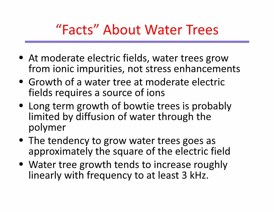
“Facts” About Water Trees
• At moderate electric fields, water trees grow from ionic impurities, not stress enhancements
• Growth of a water tree at moderate electric fields requires a source of ions
• Long term growth of bowtie trees is probably• Long term growth of bowtie trees is probably limited by diffusion of water through the polymer
• The tendency to grow water trees goes as approximately the square of the electric field
• Water tree growth tends to increase roughly linearly with frequency to at least 3 kHz.
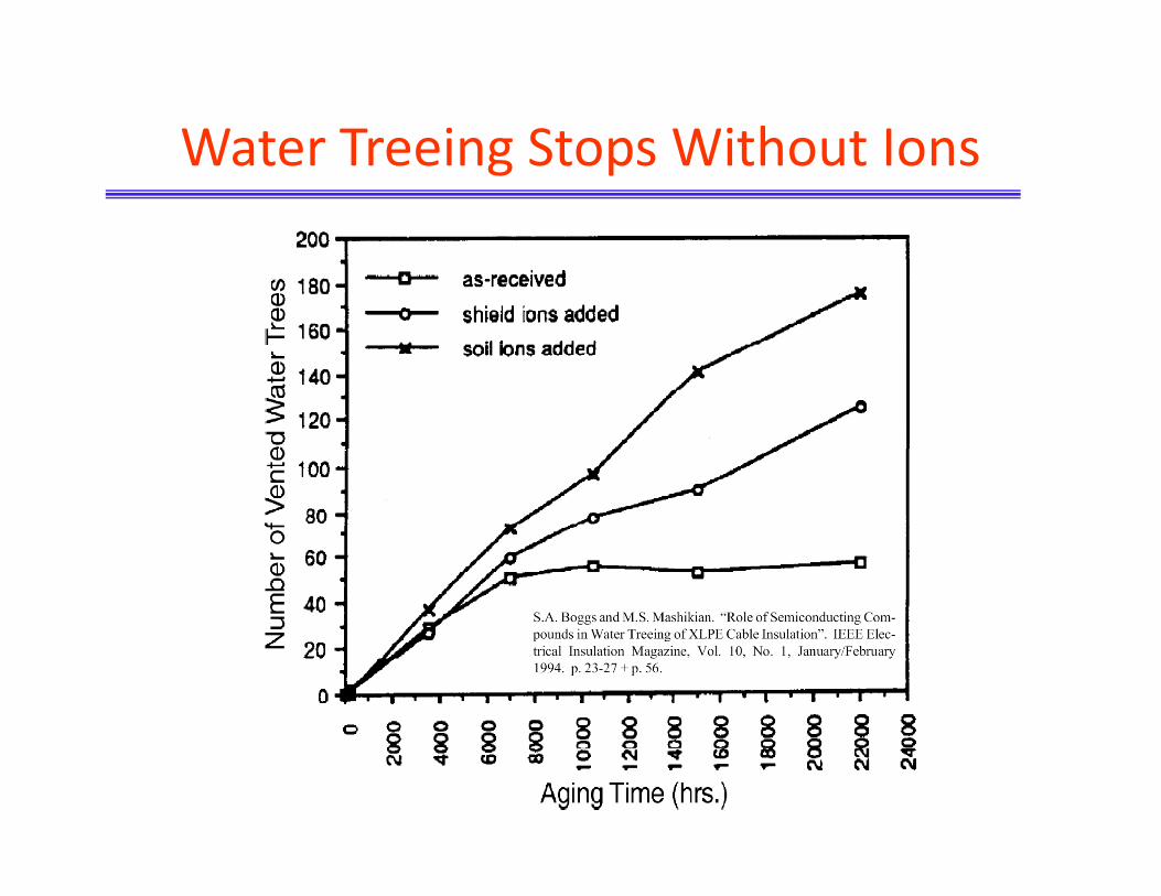
Water Treeing Stops Without Ions

Characteristics of a Chemical Potential for
Water Treeing
1. Results in self-propagation through the dielectric
2 Requires an electric field2. Requires an electric field
3. Frequency dependent
4. Depends heavily on ion concentration

Basis for Computation

Chemical Potential for Sphere
What is the relevant chemical
potential?
Positive Peak or DC Offset?
Total energy or energy in
polymer?
Zeller believed the DC offset
was the relevant potential.
But for a rapid, irreversible
reaction, it might be the
positive peak.

Chemical Potential for Water Treeing

Numerical Method
• Use program for transient nonlinear FEA
• Compute several cycles with a water
conductivity, σ• Compute several cycles with a water• Compute several cycles with a water
conductivity 1.05σ• Compute energy at each time, take difference,
and convert to chemical potential

Numerical & Analytical Computation

Analytic Approximation (Zeller) and Numerical Computation
of Chemical Potential for Two, 1 μm Diameter Spheres
Connected by a 10 nm dia., 5 μm Long Channel.
Background field: 5 kV/mm
Chemical potential goes as square of field.

Chemical Potential
• Zeller’s explanation for chemical potential seems likely and is a major step forward.
• The chemical potential can be computed numerically for axisymmetric configurations.
• The chemical potential is typically large enough to drive electro-oxidation over several orders of magnitude of water conductivity
• But knowledge of the chemical potential does not imply knowledge of the chemistry.

Laboratory Growth of Water Trees
• Water trees grow from water needle electrodes
readily and rapidly but are more electro-
mechanical than electrochemical
– Test used for very preliminary screening of materialsTest used for very preliminary screening of materials
• A good simulation of field conditions requires
semicon electrodes and takes months to grow.
– Provides a comparative test with good correlation to
field experience.

Lab Test for Water Treeing

Vented Tree Length Distribution vs Time

Mechanisms of Water Tree Resistance
• Make the polymer more hydrophillic
• Make any water in the polymer very conductive
– Add a salt to the polymerp y
• Make any water in the polymer nonconductive
– Place an ion “filter” in the system

TR-XLPE
• An early experimental compound from used
powdered NaCl in the XLPE, which was effective.
• Present TR-XLPE involves a hydrophilic additive
– One assumption would be that this additive stopsOne assumption would be that this additive stops
water tree channels by inhibiting condensation of
moisture in the electro-oxidized region.
– This can be treated as a mean free path problem.


Paths to Inhibit Water Tree Growth
• Low water conductivity
– Filter the water (mineral filled jacket)
– Clean semicons, jacket, and blocked conductor
• High water conductivity - add salt to the polymerHigh water conductivity add salt to the polymer
• Hydrophilic system (TR-XLPE and EPR)
• Low water permeability “semicons”
• Water tree growth is a balance between field
effects and hydrophobicity.
– For example if you take TR-XLPE in thin wall model
cable, you can grow water trees through the wall

Water Trees and Diagnostics
• Water trees increase dielectric loss (tan(δ))
• Water trees cause dielectric absorption
– Absorption of charge which is released, slowly, if the sample is shortedp
• Water trees cause (small) harmonic currents
• Water trees decrease insulation resistance
– But only if they grow all the way through
• Water trees cause formation of electrical trees which generate PD.

What is being Measured?
• A water tree is much more conductive than the polymer.
– In the trip region τ must be comparable to power frequency
• Such a time constant implies that the current and voltage are out of
phase substantially, i.e., dielectric loss
– In the root region, a dielectric time constant in the range of μs
• Important for the effect of lightning impulses on water treesImportant for the effect of lightning impulses on water trees.
• In the water tip region, a gradient of conductivity occurs
from the water tree to the base polymer
• Current density and position-dependent resistivity imply
formation of space charge.J=current density
ε=dielectric constant
ρ=resistivity

What is Measured?
• Under AC voltage, variation in conductivity near the water tree tip causes dissipation & increases tan(δ)
• For isothermal relaxation or recovery voltage, space charge causes a current after the cable is shorted for a few secondsshorted for a few seconds
• In all cases, an average property is being used to diagnose an extreme value
– This only works if a correlation has been established between the average property and the extreme value.
– This correlation may be cable or system specific, depending on operating conditions

Insulation Resistance
• Unless the water tree has grown ALL the way
through the dielectric, a change in IR can seldom
be observed.
U d fi ld diti l k th d b• Under field conditions, leakage paths caused by
accessories pose a major problem.
• Good way to locate water trees which have
grown through the insulation in the lab.
• Generally TERRIBLE diagnostic under field
conditions.

Impulse Reflection from Water Trees
• DC voltage was applied to cause space charge
at water trees, then a pulse was sent down the
cable, and reflections were detected from the
water trees.
• This approach was developed in the Russia and
applied in North America but damaged the
cable.
• When AC is applied, the space charge causes a
field enhancement for the reverse polarity
which tends to initiate electrical trees.

Water Trees and PD
• All past work indicates that water trees do not cause partial discharge
• However, non-PD electrical signals have been observed from water trees under laboratoryobserved from water trees under laboratory conditions by Dorris et al.
– Consistent with rapid yielding of the polymer causing a step increase in capacitance.
• Electrical trees can be associated with water trees

Water Trees with Electrical Trees
• The electrical trees were detected
i th fi ld ith PDIV f 2 t 2 5in the field with PDIV of 2 to 2.5 pu.
• The electrical trees were detected
at the same location two or three
years in a row.
• This suggests that a heavily water
treed cable is likely to have some
electrical trees which may not grow
to failure rapidly.
M. S. Mashikian and A. Szatkowski, “Medium Voltage Cable
Defects Revealed by Off-Line Partial Discharge Testing at
Power Frequency”. IEEE EI Magazine, Vol. 22, No. 4, July/Aug
2006. pp. 24-32.
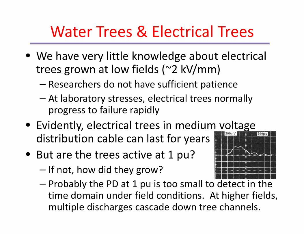
Water Trees & Electrical Trees
• We have very little knowledge about electrical trees grown at low fields (~2 kV/mm)
– Researchers do not have sufficient patience
– At laboratory stresses, electrical trees normally progress to failure rapidly
• Evidently, electrical trees in medium voltage distribution cable can last for years
• But are the trees active at 1 pu?
– If not, how did they grow?
– Probably the PD at 1 pu is too small to detect in the time domain under field conditions. At higher fields, multiple discharges cascade down tree channels.

Frequency Domain PD Detection
• PD detection is generally more sensitive, if less
quantitative, when carried out in the frequency
domain.
• Cablewise conducts PD detection in-service and
in the frequency domain to improve sensitivityin the frequency domain to improve sensitivity
• Discharge is normally observed for any heavily
water treed cable and is an indication of cable
condition.
• Water trees do not generate discharge, so this
must be caused by electrical trees.

Conclusions – PE Diagnostics
• Diagnostics based on averaged parameters are only
of value if a statistical correlation has been
developed with typical cable condition. The degree
to which such correlations can be transferred from
one system to another is not known.y
• PD from electrical trees associated with water trees
is a clear indication of poor cable condition
• Diagnostics based on non-PD electrical signals, if
real, appear promising but are not yet developed.

How Big is My Problem?
• If we analyze historical data, we can estimate
future failure rates based on an assumed in-
ground population
– But how much as already failed and been replaced?– But how much as already failed and been replaced?
– The number of splices in direct buried cable is often
much greater than utility records show
– In a duct-based system, this implies that more cable
may have been replaced than utility records indicate
– Thus the in-ground population of low quality cable
may be smaller than utility records suggest.

Options
• Replace
– Impractical in the short term
– Need basis to prioritize replacement
– Field testing can provided limited insight
• Rejuvenate
– About half the cost of replacement
– Requires that neutral be in acceptable condition
– Has a good track record for reducing failure rates
• Wait until failure

Replace – but Where?
• Routine Field Test Programs (e.g., PPL)
– Conduct continuous, system wide tests
• PD, tan(δ), depolarization current, etc.
– With criteria for accept, rejuvenate, replace
– Requires taking circuits out of service
– Over time, the failure rate has been reduced substantially
• In-Service Test Programs
– PD & concentric neutral assessment is possible in-service (without an outage)
– Objective is typically to prioritize replacement or reduce the likelihood of failure on critical circuits

Present State-of-the-Art
• A range of approaches to field PD measurement
are being marketed
• While they differ in detail, they can generally
diagnose unambiguously very bad cable and very
good cable the devil is in the details betweengood cable - the devil is in the details between
• Field PD measurement is most effective to
address a known problem
• For use to assess overall condition, PD measure-
ments are best combined with other techniques
such as dielectric loss, spectroscopy, etc.

Silicone Injection Cable Rejuvenation
• Commercialized by Dow Corning in 1987.
• Inject a low molecular weight silicone into the
conductor strands which then diffuses into the
dielectric and gels through a reaction withdielectric and gels through a reaction with
moisture in the dielectric, thereby replacing
water trees with gelled silicone.
• Applied widely as a lower cost alternative to
replacement when the neutral is in acceptable
condition.

Incomplete data for 2005
William R. Stagi, “Silicone Injection Technology”, IEEE Latin American Conference, 2006

Dielectric Strength Improves Over Time
Treatment cost is in the
range of $8/ft compared
with replacement costs of
$20 to $50/ft.
Over the past 20 years, 80
million cable feet have
been treated, 99+% of
which is still in service and
failure-free.

Conclusion
• In the long run, most of what remains of the >2
billion feet of pre-1980 PE cable will have to be
rejuvenated or replaced prematurely.
• We have a huge technical and economicWe have a huge technical and economic
problem, but one which may not be as large as
our records show, as we really do not know how
much of this cable remains in the ground.
• We have to start from the cable as it is – all we
can do technically is develop better ways to
prioritize rejuvenation and replacement.

What Can Technology Contribute?
• We need a (preferably in-service) diagnostic which
is sensitive to the worst water trees rather than
the present diagnostics which tend to react
similarly to many small trees or a few large treessimilarly to many small trees or a few large trees.
• Do water trees act as nonlinear mixers for high
frequency radiation in the cable? If so, this effect
is probably a strong function of tree length.
• Certainly water trees generate harmonic currents,
which suggests nonlinearity.


![Advanced Smart Grid Monitoring: Intelligent Cable Diagnostics ...lampe/Preprints/2020-DiagnosticsML-PLC.pdfreuse PLC modems for this purpose [8], [10], [18]–[21]. PLC-based cable](https://static.fdocuments.net/doc/165x107/610caff215c4c805600eb174/advanced-smart-grid-monitoring-intelligent-cable-diagnostics-lampepreprints2020-diagnosticsml-plcpdf.jpg)


![ESI[truck] HD Diagnostics SHEET.pdf · Tech stays at the vehicle Repair Info at the truck –Wiring Diagrams ... 12/24V cigarette lighter cable USB cable, 1.0 m Software DVD ... Scania,](https://static.fdocuments.net/doc/165x107/6074ed9d927f7e75fe16ff9c/esitruck-hd-diagnostics-sheetpdf-tech-stays-at-the-vehicle-repair-info-at-the.jpg)