CABLE CARRIERS - VAHLEINC.COM
12
CABLE CARRIERS for -tracks
Transcript of CABLE CARRIERS - VAHLEINC.COM

CABLE CARRIERSfor -tracks

ApplicationCable carriers ride on the square bar parallel to the tra-versing track of the equipment. This arrangement ensu-res that the total length of equipment (e.g. hoist, crab,trolley, etc.) is used as storage distance for the carriers(see sketch below). The first carrier (lead carrier) isconnected to the equipment by an outrigger and towedalong the diamond track.
All carriers are connected to each other via the cables orhoses installed. Depending on the cable/hose package,the loop, the speed, the acceleration and the type ofcurve radii it might be necessary to consider tension reli-ef elements.
Important for proper performance:
a) Consider min. permissible bending radii of cables
b) Consider a cable loop safety length of 10-15% forstraight runs and 20% for curved tracks.
LayoutThe types of cables are determined according to therequired number of conductors and the current load ofthe equipment (see cat. 8L). The dimensions of cablesare the basis for the selection of the carrier type. Thelength of cable results from active travel distance plusstorage distance, extra safety length plus end connec-tions (see installation information).
Consider a multiplier of 0.7 x smallest radius for themaximum permissible cable loop in curved installations.The maximum permissible speed depends on the totalamount of curve angles.
For systems specification please refer to the example forordering in this catalog.
We welcome your inquiry on your particular application.Kindly consult your local Vahle agent or the factory usingthe questionnaire and submitting a system layout.
VAHLE FESTOON SYSTEMS
2
19 12
CONTENTS PageGeneral information 2
Questionnaire 3
Diamond Track V 3 and Accessories 4, 5
Cable Carriers for V 3 5
Lead Carriers and Track Clamps for V 3 6
Control Carriers and Accessories for V 3 7
Example for Ordering 8
Installation Tools, diagram 9
Table determining the storage distance and number of carriers 10, 11
GeneralVAHLE-Festoon systems support electric cables or hoses for mobile machinery.
The cable carriers contained in this catalog comply with VDE regulations. Diamond tracks are especially well suited forcurved installations.
Catalog No. 8a Cable Carriers on -TracksCatalog No. 8bF Cable Carriers for flatform cable on -Beam TracksCatalog No. 8bR Cable Carriers for round cable on -Beam TracksCatalog No. 8c Cable Carriers on -TracksCatalog No. 8L Conductor Cables and Fittings

QUESTIONNAIRE
3
19 12
No. of No. & size of ø width x thicknesscables conductors mm of flatform cables
Name and Adress of Customer:
Ref.:
1. Type of Application
2. Outdoors ■■ indoors ■■
3. Temperature range °C min. °C max.
4. Is round or flatform cable envisaged?
5. How much space is available for storage? mm
6. Is it possible to extend the track for the festoon cable system in case the length of equipment is insufficient for storage space?
■■ Yes, by mm, ■■ no, not possible.
7. Special operating conditions:
8. Length of crane trolley: mm
9. Travel distance of crane trolley: mm
10. Travelling speed: m/min.
11. Max. loop depth: mm
12. Further details:
12. Required cables:
Please, submit the completed Questionnaire together with your inquiry. Your system layout drawing will be appreciated incase of curves.

Dim A depends on width of machinery (e.g. crane trolley).Make sure that hoist wheels haveenough clearance.
Type Material Surface Weight A (adjustable) L Cat. no.protection kg mm mm max. B mm
HK 200 0.980 200 400 210* 310 220
HK 300 steel galvanized 1.130 300 500 210* 310 230
HK 400 1.290 400 600 210* 310 240
HK 500 1.430 500 700 210* 310 250
Our delivery: 1 pair of claws and track S1. Hangers AKV 3 to be ordered separately.
* Select next larger size bracket when your I-beam dimension B is more than 210 mm.
V 3 TRACK AND ACCESSORIES
4
19 12
Type V 3
Cat. no. 360 196
For cable carrier WV 3
Material steel
Surface protection galvanized
Supply lengths 6 mStandard support spacing 2 m (1 m in storage
section and curves)
Moment in inertia Jx 2.94 cm4
Section modulus Wx 1.39 cm3
Weight 1.77 kg/m
Other support centers and permissible area loads
Support spacing 1 m 1.5 m 2 m 2.5 m 3 m 3.5 m
perm. area load 111 kg 74 kg 47 kg 30 kg 21 kg 15 kg
Type VV 3
Cat. no. 360 018
Material steel/aluminium
Surface protection galvanized
Weight 0.125 kg
2 bolts M 6 x 30, cat. no. 360 030to be ordered separately
Track
Type KV 3
Cat. no. 360 023
Material polyethylene
Weight 0.008 kg
Type ADV 3
Cat. no. 360 019
Material steel/aluminium
Surface protection galvanized
Weight 0.11 kg
Type AKV 3
Cat. no. 360 020
Material steel/aluminium
Surface protection galvanized
Weight 0.19 kg
Joint clamp End cap
Hangerunderhung
Support bracket
Hangerunderhung for HK support
ACCESSORIES AND CABLE CARRIERS FOR V 3 TRACK
5
19 12
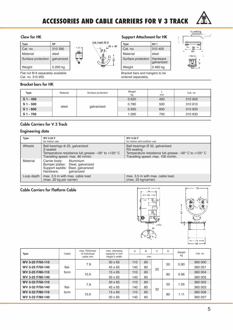
Type Material Surface protection Weight L Cat. no.kg mm
S 1 - 400 0.620 400 310 600
S 1 - 500steel galvanized
0.780 500 310 610
S 1 - 600 0.930 600 310 620
S 1 - 700 1.090 700 310 630
Flat nut M 8 separately availableCat. no. 310 955.
Bracket bars and hangers to be ordered separately.
Type SP
Cat. no. 310 390
Material steel
Surface protection galvanized
Weight 0.200 kg
Type AH 1
Cat. no. 310 400
Material steel
Surface protection Hardwaregalvanized
Weight 0.460 kg
Claw for HK Support Attachment for HK
Bracket bars for HK
Cable Carriers for Flatform Cable
Cable Carriers for V 3 Track
Engineering data
Type WV 3-25 F WV 3-32 Ffor indoor use for indoor and outdoor use
Wheels Ball bearings ø 25, galvanized Ball bearings Ø 32, galvanizedZ-sealed RS-sealingTemperature resistance lub grease: –30° to +125° C Temperature resistance lub grease: –30° C to +125° CTravelling speed: max. 80 m/min. Travelling speed: max. 100 m/min.
Material Carrier body: AluminiumBumper plates: Steel, galvanizedSupport saddle: Steel, galvanizedHardware: galvanized
Loop depth max. 3.5 m with max. cable load max. 3.5 m with max. cable load,(max. 20 kg per carrier) (max. 25 kg/carrier)
max. thickness max. clamping A B C DType Cable of individual capacity in mm Weight Cat. no.
cable mm height x width mm kg
WV 3-25 F/50-1107.9
30 x 65 110 6050 0.90
360 000
WV 3-25 F/50-140 flat- 45 x 65 140 8025
360 001
WV 3-25 F/80-110 form10.0
15 x 65 110 6080 0.96
360 004
WV 3-25 F/80-140 30 x 65 140 60 360 005
WV 3-32 F/50-110 30 x 65 110 6050 1.05
360 002
WV 3-32 F/50-140 flat-7.9
45 x 65 140 8032
360 003
WV 3-32 F/80-110 form10.0
15 x 65 110 6080 1.11
360 006
WV 3-32 F/80-140 30 x 65 140 60 360 007

Type for Cable carriers Cable A Weight Cat. no.mm kg
MV 3-25 F/50-110 WV 3-25 F/50-110 1101.27
360 008
MV 3-25 F/50-140 WV 3-25 F/50-140 flat- 140 360 009
MV 3-25 F/80-110 WV 3-25 F/80-110 form 1101.33
360 012
MV 3-25 F/80-140 WV 3-25 F/80-140 140 360 013
MV 3-32 F/50-110 WV 3-32 F/50-110 1101.42
360 010
MV 3-32 F/50-140 WV 3-32 F/50-140 flat- 140 360 011
MV 3-32 F/80-110 WV 3-32 F/80-110 form 1101.48
360 014
MV 3-32 F/80-140 WV 3-32 F/80-140 140 360 015
Type for Cable carriers Cable Weight Cat. no.kg
WV 3-25 F/50-110
EV 3-F/50WV 3-25 F/50-140
flatform 0.66 360 016WV 3-32 F/50-110
WV 3-32 F/50-140
WV 3-25 F/80-110
EV 3-F/80WV 3-25 F/80-140
flatform 0.73 360 017WV 3-32 F/80-110
WV 3-32 F/80-140
V 3 LEAD CARRIERS AND TRACK CLAMPS
6
19 12
Lead Carriers for flat form Cable
Track clamps c/w bumper for flatform Cable

7
Type PV 3
Cat. no. 360 021
Material steel/aluminium
Weight 0.49 kg
V 3 CONTROL CARRIERS AND ACCESSORIES 19 12
Bumperrequired c/w control carriers
Type ZEK
Cat. no. 360 027
Material steel
Surface Protection galvanized
Weight kg/m 0.075
X = (F x 1.05) + Zn + 1
X = Chain length in mmF = Travel distance of lead carrier in mmn = Number of cable carriers
(w/o lead carriers and end clamps)1.05 = Safety length factorZ = Open space in storage section
(see page 11, point 5)
Accessories:
Each piece of chain requires:2 chain buckles, type KSS, cat. no. 360 028.
Each Track clamp requires:1 ring screw RS, cat. no. 360 029.
Control Carriers
Type*
ST-V3-32/A1
Cable glandsmax.
numberA-Side
max.numberB-Side
ST-V3-32/A2
Cable glandsmax.
numberA-Side
max.numberB-Side
D E F Gmm Weight kg Cat. no.
ST-V3-32/A1 190 150 38 100 4.9 360 138ST-V3-32/A2 280 200 62 140 6.3 360 139
PG 16 6 2PG 21 5 1PG 29 3 1PG 36 2 1PG 42 2 –PG 48 2 –
PG 16 12 6PG 21 10 6PG 29 8 4PG 36 4 1PG 42 3 1PG 48 3 1
Execution
Carrier body: aluminium Support bar: aluminiumWheels: steel ball bearings Terminal box: norylMax. cable load: 25 kgTemperature resistance: – 30° C to + 100° C
Max. length of Terminal block A1 = 130 mmA2 = 220 mm
26
GF
ø32110
E
A C
B
155
D
435
50
119
TerminalBlock
Strain Relief Chain c/w Accessories
Attention: The junction box is to be grounded with terminal block Type EK 2.5 N PA!

Travelling speed: 30 m /min.
Cables: 1 PVC-flatform (K) H 07 VV H 2 - F 4 G 4 (7.1 x 22 mm)1 PVC-flatform (K) H 07 VV H 2 - F 8 G 2.5 (5.9 x 35.7 mm)
max. Cable loop depth: 1 m (per structural environment)
required hookup cable end connections: 1 x 2 m + 1 x 5 m
* Curves up to a total length of 5.5 m are available. We cut the 180 degree in two for easier shipping.
EXAMPLE FOR ORDERING
8
19 12
Inquiry: Hoist on track per drawing – Indoor Installation –
How to select the correct system:
1. Calculation of lead carrier’s active travel
3000 mm +2 x 1000 mm x x 90°
+360°
1000 mm +2 x 1300 mm x x 180°
+ 3000 mm = 12660 mm360°
2. Max. permissible cable loop depth (see page 9)0.7 x Rmin. = 0.7 x 1000 mm = 700 mm(Rmin. = smallest curve radius of the system)
3. Checking the travelling speed(see diagram page 9)Total of curve angles: 90° + 180° = 270°Smallest curve radius: 1000 mmThat means okay for max. travelling speed of 30 m/min.
4. Selection of carriers (see page 5) WV 3-25 F/50-110
5. Find out the quantity of carriers required(see diagram, pages 10/11). 11 pcs
6. Find out the storage distance (see page 10)plus 1 carrier length open space1350 mm + 110 mm = 1460 mm
7. Find out length of each strain relief chain(see formula page 7)
X =(12 660 x 1.05) + 110 mm
= 1117 mm12
Total chain length: 12 x 1117 mm = 13404 mm �= 14 m
8. Length of cable required (chain length + storage distance)x cable loop safety length + 7000 mm for hockup cableend connections (12 660 + 1460 mm) x 1.2 + 7000 mmfor connections �= 24 m
Material to order:
Qty material cat. no.
14.555 square bar track, type V 3in 1 x 4.7 m 360 195
1 x 1.571 m (curve) 360 1921 x 1 m 360 1912 x 2.042 m (curves) 360 1931 x 3.2 m 360 194
extras for curved sections 1 x 90° R = 1000, L = 1571 mm 360 1922 x 180° R = 1300, L = 2 x 2042 mm * 360 193
Surcharge for bending per section 360 0265 joint clamps VV 3 360 018
2 end caps KV 3 360 023
17 hangers AKV 3 360 020
17 brackets HK 500 310 250
11 cable carriers WV 3-25 F/50-110 360 000
1 lead carrier MV 3-25 F/50-110 360 008
1 track clamp with bumper EV 3-F/50 360 016
14 m chain ZEK 360 027
24 chain buckles KSS 360 028
1 ring screw RS 360 02924 m plastic flat cable (K)
H 07 VV H 6-F 4 G 4 (7.1 x 22 mm) 331 35924 m plastic flat cable (K)
H 07 VV H 6-F 8 G 2.5 (5.9 x 35.7 mm) 331 357
2 cable glands Pg 29 for 4 x 4 mm2 330 920
2 cable glands Pg 36 for 8 x 2.5 mm2 330 990
1 drill-jig BV 3-50/15 360 024
1 dril ø 8.5 x 90° 360 032

9
19 12INSTALLATION TOOLS AND DIAGRAM
Drill-jig(see installation information)
Type BV 3-50/15
Cat. no. 360 024
Material aluminium, drill insertshardened steel
Weight 0.75 kg
Spiral Driller
Type Ø 8.5 x 90°
Cat. no. 360 032
Material HSS steel
Angle of Drill <= 90°.
Max. permissible cable loop for installations with curves
= 0.7 x smallest curve-radius of track layout
Diagram for permissible travelling speed in curves

10 In accordance with our company’s policy of continued improvement, we reserve the right to amend specifications and details at any time.
(The Diagram considers a cable loop safety length of 20%)
1. The active travel distance of the lead carrier to be plotted on the horizontal axis (equals the machinery travelling distance with straight runs; in case of curves see runway calculation on page 8).
2. Draw an upward vertical line from this point.
3. Where this vertical axis upward intersects with the sloping line (loop depth; also see formulaon page 9) now draw a horizontal axis to the left.
For straight runs → machinery travelling distance in metersFor curved runs → active travel distance of lead carrier in meters
Numberof
carriers
Numberof
carriers
WV 3-25 F/50-110WV 3-25 F/80-110WV 3-32 F/50-110WV 3-32 F/80-110
WV 3-25 F/50-140WV 3-25 F/80-140WV 3-32 F/50-140WV 3-32 F/80-140
carrier type
storage distance (mm) w/o factor Z
55 6190 784054 6080 770053 5970 756052 5860 742051 5750 728050 5640 714049 5530 700048 5420 686047 5310 672046 5200 658045 5090 644044 4980 630043 4870 616042 4760 602041 4650 588040 4540 574039 4430 560038 4320 546037 4210 532036 4100 510035 3990 504034 3880 490033 3770 476032 3660 462031 3550 448030 3440 434029 3330 420028 3220 406027 3110 392026 3000 378025 2890 364024 2780 350023 2670 336022 2560 322021 2450 308020 2340 294019 2230 280018 2120 266017 2010 252016 1900 238015 1790 224014 1680 210013 1570 196012 1460 182011 1350 168010 1240 15409 1130 14008 1020 12607 910 11206 800 9805 690 8404 580 7003 470 5602 360 4201 250 280
storage distance (mm) w/o factor Z
55545352515049484746454443424140393837363534333231302928272625242322212019181716151413121110987654321
10 20 30 40 50 60 70
0.90
m
0.80
m
0.70
m
0.60
m
0.50
m
DETERMINING STORAGE DISTANCEAND NUMBER OF CARRIERS19 12

11
DETERMINING STORAGE DISTANCEAND NUMBER OF CARRIERS 19 12
4. There, at the vertical axis you find the required number of carriers, track clamp and lead carrier not included. Always select the next larger quantity when your line ends up between two numbers.
5. The table on the left shows the required storage distance for the choosen type and number of car-riers (considering all carriers, 1/2 of lead carrier and 1/2 of track clamp pushed closely together).Allow approx. one carrier length for the open space Z (see details on page 3).
80 90 100 110 120 130 140 150 160
4.50 m
4.00 m
3.50 m
3.00 m
2.75 m
2,50 m
2.25 m
1.75 m
1.50 m
1.25
m
1.00
m
Lopp depth 2.00 m
Catalog No. 8c/E 2003
0308
· P
rinte
d in
Ger
man
y · 2
003-
1920
· 10
00 ·
8/03
PAUL VAHLE GMBH & CO. KG · D 59172 KAMEN/GERMANY · TEL. 0 23 07/ 70 40Internet: www.vahle.de · e-mail: postmaster @ vahle.de · FAX 0 23 07/ 70 44 44
Catalog No.
Copperhead Conductor Systems 1 aBattery Charging Systems 1 bInsulated Conductor Systems U 10 2 aInsulated Conductor Systems U 20 – U 30 – U 40 2 bInsulated Conductor Systems U 15 – U 25 – U 35 2 cAluminium Enclosed Conductor Systems LSV – LSVG 3 aPowerail Enclosed Conductor Systems KBSL – KSL – KSLT – KSG 4 aPowerail Enclosed Conductor Systems VKS – VKL 4 bPowerail Enclosed Conductor System MKLD – MKLF – MKLS 4 cHeavy Enclosed Conductor Systems 5Trolley Wire and Accessories 6Cable Tenders 7Cable Carriers for -tracks 8 aCable Carriers for Flatform Cable on -beams 8 bFCable Carriers for Round Cable on -beams 8 bRCable Carriers for -tracks 8 cConductor Cables and Fittings 8 LSpring Operated Cable Reels 9 aVAHLE POWERCOM® – Data Transmission Systems 9 cCPS® – Contactless Power Supply 9 dSMG – Slotted Microwave Guide 9 eWCS – Position Encoding System 9 fMotor Powered Cable Reels 10
DQS-zertifiziert nachDIN EN ISO 9001
(Reg. Nr. 3140)


![TS - SGCS1 [a4] [v6] · providers, multinational enterprises and telecommunications carriers. Ownership of the region’s most extensive high-capacity submarine cable systems with](https://static.fdocuments.net/doc/165x107/5fd81bfa35b3d509cd054023/ts-sgcs1-a4-v6-providers-multinational-enterprises-and-telecommunications.jpg)