Cable Assembly Instructions for RJ45 - GreenHeat...
2
Cable Assembly Instructions for RJ45 Pair # Wire Pin # White/Blue 5 1- White/Blue Blue 4 White/Orange 1 2- White/Orange Orange 2 White/Green 3 3- White/Green Green 6 White/Brown 7 4- White/Brown Brown 8 << 568-B Diagram 1. Skin off cable jacket approximately 1” or slightly more. 2. Un-twist each pair, and straighten each wire between the fingers. 3. Place the wires in the order of the diagram shown above (568B). Bring all of the wires together, until they touch. 4. At this point, recheck the wiring sequence with the diagram. 5. Optional: Make a mark on the wires at ½” from the end of the cable jacket. 6. Hold the grouped (and sorted) wires together tightly, between the thumb, and the forefinger. 7. Cut all the wires at a perfect 90 degree angle from the cable at ½” from the end of the cable jacket. This is a very critical step. If the wires are not cut straight, they may not all make contact. We suggest using a pair of scissors for this purpose. 7B. Conductors should be at a straight 90 degree angle, and be ½” long, prior to insertion into the connector.
Transcript of Cable Assembly Instructions for RJ45 - GreenHeat...

Cable Assembly Instructions for RJ45
Pair # Wire Pin # White/Blue 5 1- White/Blue Blue 4 White/Orange 1 2- White/Orange Orange 2 White/Green 3 3- White/Green Green 6 White/Brown 7 4- White/Brown Brown 8
<< 568-B Diagram
1. Skin off cable jacket approximately 1” or slightly more. 2. Un-twist each pair, and straighten each wire between the
fingers. 3. Place the wires in the order of the diagram shown above
(568B). Bring all of the wires together, until they touch. 4. At this point, recheck the wiring sequence with the
diagram. 5. Optional: Make a mark on the wires at ½” from the end
of the cable jacket. 6. Hold the grouped (and sorted) wires together tightly,
between the thumb, and the forefinger. 7. Cut all the wires at a perfect 90 degree angle from the
cable at ½” from the end of the cable jacket. This is a very critical step. If the wires are not cut straight, they may not all make contact. We suggest using a pair of scissors for this purpose.
7B. Conductors should be at a straight 90 degree angle, and be ½” long, prior to insertion into the connector.
Therma-Ray Inc. 670 Wilsey Road, Unit 6 Fredericton, NB E3B 7K4 Tel: (506) 457-4600 Fax: (506) 457-4699 www.thermaray.com Email: [email protected]
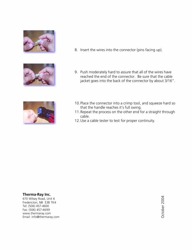
8. Insert the wires into the connector (pins facing up).
9. Push moderately hard to assure that all of the wires have reached the end of the connector. Be sure that the cable jacket goes into the back of the connector by about 3/16”.
10. Place the connector into a crimp tool, and squeeze hard so that the handle reaches it’s full swing.
11. Repeat the process on the other end for a straight through cable.
12. Use a cable tester to test for proper continuity.
Oct
ober
200
4