CA285001EN PST Pad-Mounted Switchgear with iST … pad-mounted switchgear with iST control ... time...
16
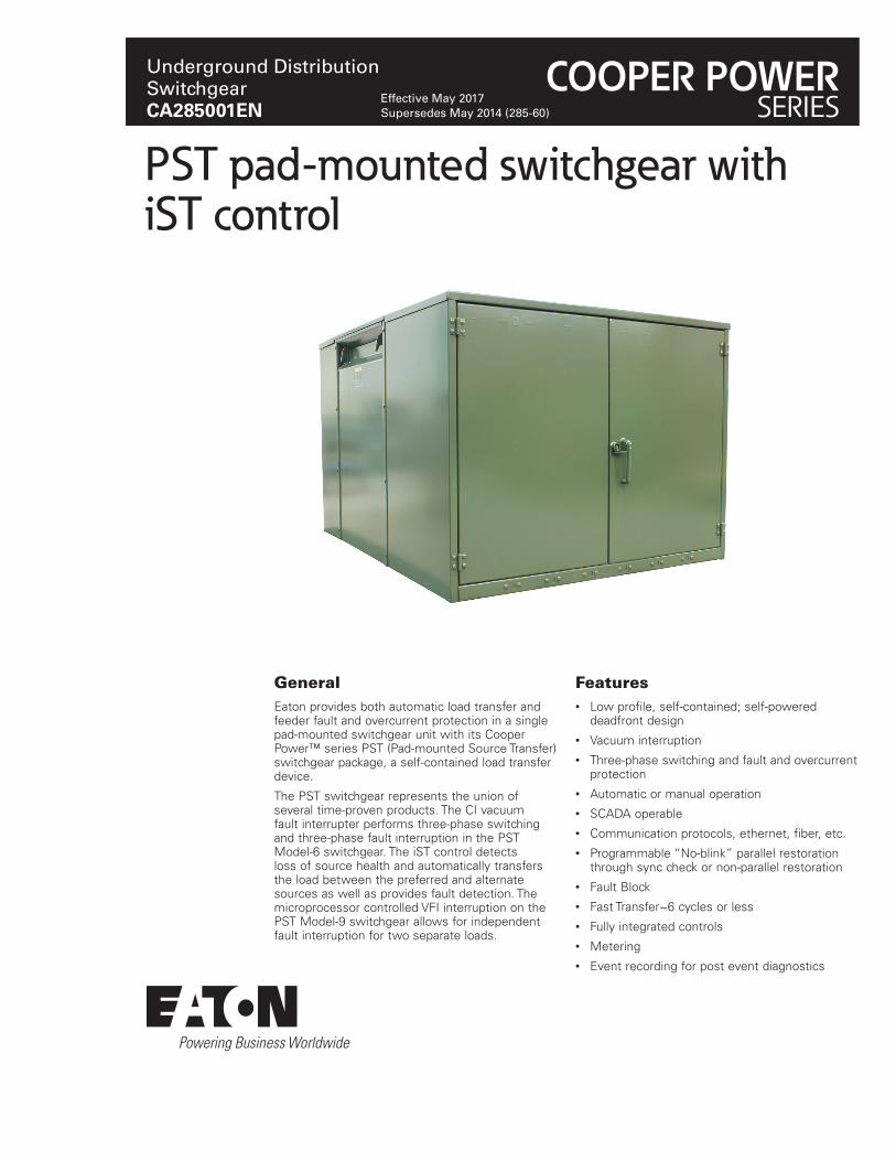
PST pad-mounted switchgear with iST control General Eaton provides both automatic load transfer and feeder fault and overcurrent protection in a single pad-mounted switchgear unit with its Cooper Power™ series PST (Pad-mounted Source Transfer) switchgear package, a self-contained load transfer device. The PST switchgear represents the union of several time-proven products. The CI vacuum fault interrupter performs three-phase switching and three-phase fault interruption in the PST Model-6 switchgear. The iST control detects loss of source health and automatically transfers the load between the preferred and alternate sources as well as provides fault detection. The microprocessor controlled VFI interruption on the PST Model-9 switchgear allows for independent fault interruption for two separate loads. Features • Low profile, self-contained; self-powered deadfront design • Vacuum interruption • Three-phase switching and fault and overcurrent protection • Automatic or manual operation • SCADA operable • Communication protocols, ethernet, fiber, etc. • Programmable “No-blink” parallel restoration through sync check or non-parallel restoration • Fault Block • Fast Transfer−6 cycles or less • Fully integrated controls • Metering • Event recording for post event diagnostics Underground Distribution Switchgear CA285001EN Effective May 2017 Supersedes May 2014 (285-60) COOPER POWER SERIES
Transcript of CA285001EN PST Pad-Mounted Switchgear with iST … pad-mounted switchgear with iST control ... time...
PST pad-mounted switchgear with iST control
GeneralEaton provides both automatic load transfer and feeder fault and overcurrent protection in a single pad-mounted switchgear unit with its Cooper Power™ series PST (Pad-mounted Source Transfer) switchgear package, a self-contained load transfer device.
The PST switchgear represents the union of several time-proven products. The CI vacuum fault interrupter performs three-phase switching and three-phase fault interruption in the PST Model-6 switchgear. The iST control detects loss of source health and automatically transfers the load between the preferred and alternate sources as well as provides fault detection. The microprocessor controlled VFI interruption on the PST Model-9 switchgear allows for independent fault interruption for two separate loads.
Features• Low profile, self-contained; self-powered
deadfront design• Vacuum interruption• Three-phase switching and fault and overcurrent
protection• Automatic or manual operation• SCADA operable• Communication protocols, ethernet, fiber, etc.• Programmable “No-blink” parallel restoration
through sync check or non-parallel restoration• Fault Block• Fast Transfer−6 cycles or less• Fully integrated controls• Metering• Event recording for post event diagnostics
Underground Distribution SwitchgearCA285001EN
Effective May 2017 Supersedes May 2014 (285-60)
COOPER POWERSERIES
Automatic source transferAll electrical distribution systems are subject to service interruptions and outages; however, there are many critical loads which cannot tolerate prolonged service interruptions. For such applications, a load-transfer scheme is used to minimize outage times. In a load transfer scheme, power is normally supplied from a preferred source and is automatically switched to an alternate source (utility or backup generation), if the preferred source health is degraded for any reason. Upon restoration of preferred source health the load can automatically be switched back, in either a parallel-return mode (preferred-source switch closes before alternate source switch opens) or a non-parallel return mode (alternate-source switch opens before preferred-source switch closes). The parallel-return transfer mode eliminates an outage when switching back to the preferred source; however, the sources must be in synch to avoid excessive current flows between the two sources.
Product descriptionThe Pad-mounted Source Transfer (PST) package provides protection against loss of source health as well as overcurrent and fault protection for critical loads. It features deadfront source and tap cable compartments, and a sealed tank, which houses the switching and fault interrupting components.
Source compartment
The source compartment houses the preferred and alternate source cable connections, the controls, and handles for manual operation of the source switches.
Tank
The PST switchgear tank contains: six potential transformers, which provide input to the iST control system to monitor the source health; current transformers, which provide input to the iST control system, to sense overload and fault conditions; two three-phase, Type CI interrupters, which perform the three-phase switching and PST Model-6 fault interruption; and, insulating liquid, which serves as the dielectric medium.
Tap compartment
The tap compartment houses the tap cables and connections, as well as the manual operation handles for the two VFI fault interrupters on the PST Model-9 switchgear.
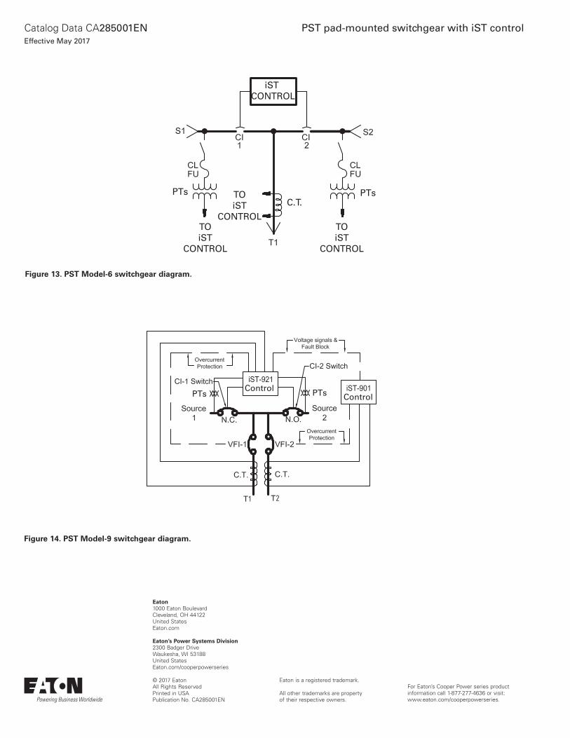
Optional configurationThe PST switchgear is designed in the industry-standard Model-6 configuration (Figure 12) however, occasionally two critical loads must be served, each independently, from the same source. To accommodate this need, the PST can be provided in a Model-9 configuration (see Figure 13). The Model-9 configuration is supplied with an iST-921 control and an iST-901 control. Each control operates a separate three-phase interrupting VFI with the iST-921 control providing the source transfer logic. This arrangement of two separate controls, operating VFI interrupters, provides independent overcurrent and fault protection for the critical loads serviced by each tap.
CI technology
Switching and fault interruption are both accomplished with Eaton’s Cooper Power series motor-charged, Type CI interrupters. The CI interrupters feature our long-life, maintenance free, vacuum interrupters, which assure many years of trouble free performance.
When energized, a motor winds the CI interrupter mechanism to charge the closing and opening springs; this provides quick-close and quick-open operation of the vacuum interrupters. Each CI interrupter can also be operated manually, should control power be lost. A hotstick-operable lever can be operated to manually close or trip the CI interrupter, while a hotstick-operable push-pull handle can be operated for manual charging of the springs. Viewing ports provide access to the contact position indicators and operation counters for each interrupter.
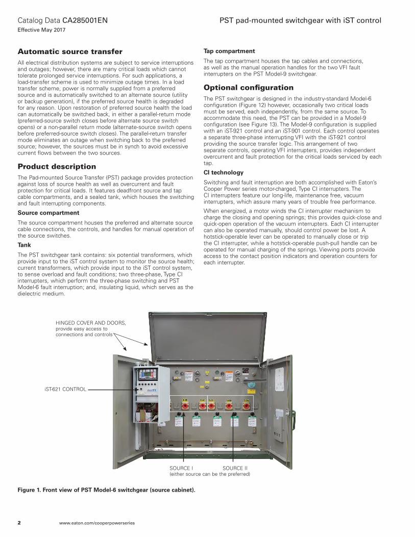
HINGED COVER AND DOORS, provide easy access to connections and controls
SOURCE I SOURCE II(either source can be the preferred)
iST-621 CONTROL
Figure 1. Front view of PST Model-6 switchgear (source cabinet).
2
Catalog Data CA285001ENEffective May 2017
PST pad-mounted switchgear with iST control
www.eaton.com/cooperpowerseries
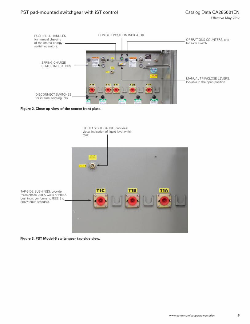
PUSH-PULL HANDLES, for manual charging of the stored energy switch operators.
SPRING CHARGE STATUS INDICATORS
MANUAL TRIP/CLOSE LEVERS, lockable in the open position.
OPERATIONS COUNTERS, one for each switch
LIQUID SIGHT GAUGE, provides visual indication of liquid level within tank.
TAP-SIDE BUSHINGS, provide three-phase 200 A wells or 600 A bushings, conforms to IEEE Std 386™-2006 standard.
Figure 2. Close-up view of the source front plate.
Figure 3. PST Model-6 switchgear tap-side view.
CONTACT POSITION INDICATOR
DISCONNECT SWITCHES for internal sensing PTs
3
Catalog Data CA285001ENEffective May 2017
PST pad-mounted switchgear with iST control
www.eaton.com/cooperpowerseries
iST controliST relay
The iST family of source transfer relays for two sources is a member of the Eaton’s Cooper Power series Edison® Idea™ line of protective relays. The iST relay family consists of the iST-621 for single feeder applications, and iST-921 and iST-901 for two feeder applications. The iST relay family also provides advanced metering, control, and communications, and event analysis tools.
The iST relays use ProView® application software for PCs running the Microsoft® Windows® operating system. The Idea Workbench™ feature of ProView permits the user to add additional functionality.
Applications
The iST relays are designed for applications with one or two feeders. • The iST-621 is the source transfer relay for configurations with
two sources and a single feeder. Phase and ground overcurrent protection for the feeder is included.
• The iST-921 and iST-901 relays are designed for use as a pair on two feeder applications. • The iST-921 is the source transfer relay for two sources and
includes phase and ground overcurrent protection for the first feeder.
• The iST-901 relays provides phase and ground overcurrent protection for the second feeder.
To address the needs of automation, Energy Management Systems (EMS), and SCADA systems, the iST family of relays provide advanced power quality, load (tap) metering, control, and communications capabilities.
Transfer logic
The comprehensive transfer logic includes the following features:
Five source preference selections:• Source 1 preferred; Normal restoration• Source 1 preferred; Hold on alternate• Source 2 preferred; Normal restoration• Source 2 preferred; Hold on alternate• No Source Preference
Normal restorations can be either Non-parallel with an adjustable time delay, or Parallel with sync-check.
The Parallel with Sync Check Restoration Mode supervises source closing for both automatic and manual operations. The Sync Check function compares the phase rotation, voltage magnitude, phase angle, and frequency of both sources. Paralleling of the sources is permitted only when all parameters are within the customer-configurable thresholds. In automatic mode, it permits closing the preferred source prior to opening the alternate source to achieve a “blinkless” transfer.
In manual mode, the Sync Check function prevents accidental paralleling of non-synchronous sources. If parallel restoration is not enabled, both source switches cannot be closed in manual mode from the relay panel.
The alternate source can be either a utility line or a generator. Settings for generator startup time, standby time, and shutdown time are included.
There are seven independent parameters for Source Health. Each has a settable threshold and time delay.
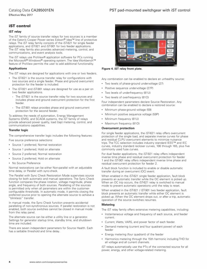
Any combination can be enabled to declare an unhealthy source: • Two levels of phase-ground undervoltage (27)• Positive sequence undervoltage (27P)• Two levels of underfrequency (81U)• Two levels of overfrequency (81O)
Four independent parameters declare Source Restoration. Any combination can be enabled to declare a restored source:• Minimum phase-ground voltage (59)• Minimum positive sequence voltage (59P)• Minimum frequency (81U)• Maximum frequency (81O)
Overcurrent protection
For single feeder applications, the iST-621 relay offers overcurrent protection of the single load, and separate inverse curves for phase and residual CLPU overcurrent elements to minimize nuisance trips. The TCC selection includes industry standard IEEE™ and IEC curves, industry standard recloser curves, 106 through 165, plus five commonly used fuse curves.
For dual feeder applications, the iST-921 relay offers independent inverse time phase and residual overcurrent protection for feeder 1 and the iST-901 relay offers independent inverse time phase and residual overcurrent protection for feeder 2.
A fault block function is included to enable or disable automatic transfer during an overcurrent (OC) event.
When enabled in the iST-621 single feeder application, fault block prevents an automatic transfer while the OC element is picked up. When an OC trip occurs, the iST-621 relay is switched to manual mode to prevent automatic operations until the relay is reset.
When enabled in the iST-921 / iST-901 two feeder application, fault block prevents an automatic transfer while either OC element is picked up. When the OC element drops out, or after a trip, automatic operation of the source switches resumes.
Metering
The iST relay family offers extensive metering capabilities, including:• Instantaneous voltage and frequency of each source, and feeder
current.• Current, Watts, VARS, and power factor of each feeder.• Demand metering (current and four quadrant power) of each
feeder• Energy metering (four quadrant) of the feeder• Harmonics metering through the 15th harmonic including THD for
all voltage and all current channels.
iST relays automatically use the PTs of the connected source for all power, energy, and other voltage-related metering.
Figure 4. iST relay front plate.
4
Catalog Data CA285001ENEffective May 2017
PST pad-mounted switchgear with iST control
www.eaton.com/cooperpowerseries
Use the Idea Workbench feature to customize the iST relays
The iST is a fully functional family of relays, ready to use right out of the box. However, there are applications where custom control logic, or custom functions need to be added to the relay. The Idea Workbench feature is a revolutionary graphical software programming environment which permits the user to customize the iST relays.• Add new features or protective functions by means of Idea
Workbench Custom Modules. These operate in the same fashion as the plug-ins for popular internet browsers. Your investment in the relay is protected as future needs and developments may be addressed through new Custom Modules.
• Create custom control and protection logic using over 400 programming signals and tools, all selectable from drag-off Toolboxes. Logic created using these tools can then be saved as Custom Modules to be reused or shared with associates.
• Monitor and control practically every aspect of the relay’s operation.• Create custom metering and measurement quantities.• Create custom sequence of event records.• Configure communication protocols to match existing SCADA
system mappings.
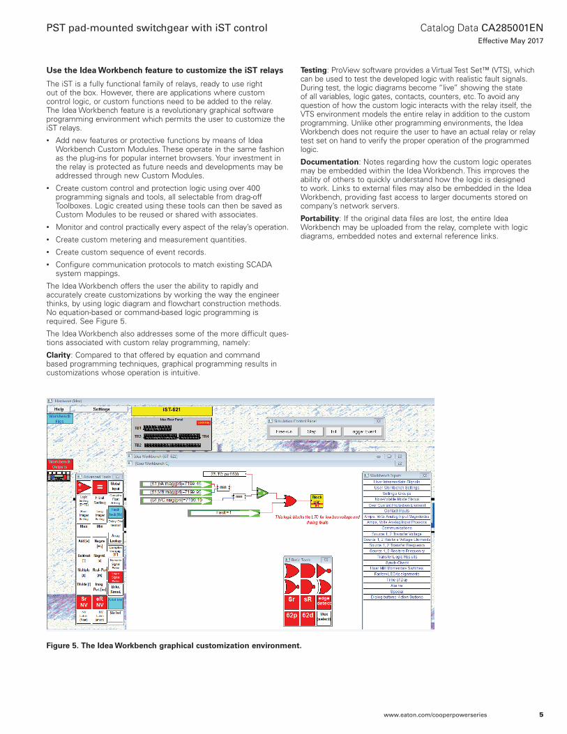
The Idea Workbench offers the user the ability to rapidly and accurately create customizations by working the way the engineer thinks, by using logic diagram and flowchart construction methods. No equation-based or command-based logic programming is required. See Figure 5.
The Idea Workbench also addresses some of the more difficult ques-tions associated with custom relay programming, namely:
Clarity: Compared to that offered by equation and command based programming techniques, graphical programming results in customizations whose operation is intuitive.
Testing: ProView software provides a Virtual Test Set™ (VTS), which can be used to test the developed logic with realistic fault signals. During test, the logic diagrams become “live” showing the state of all variables, logic gates, contacts, counters, etc. To avoid any question of how the custom logic interacts with the relay itself, the VTS environment models the entire relay in addition to the custom programming. Unlike other programming environments, the Idea Workbench does not require the user to have an actual relay or relay test set on hand to verify the proper operation of the programmed logic.
Documentation: Notes regarding how the custom logic operates may be embedded within the Idea Workbench. This improves the ability of others to quickly understand how the logic is designed to work. Links to external files may also be embedded in the Idea Workbench, providing fast access to larger documents stored on company’s network servers.
Portability: If the original data files are lost, the entire Idea Workbench may be uploaded from the relay, complete with logic diagrams, embedded notes and external reference links.
Figure 5. The Idea Workbench graphical customization environment.
5
Catalog Data CA285001ENEffective May 2017
PST pad-mounted switchgear with iST control
www.eaton.com/cooperpowerseries

Event records and analysis tools
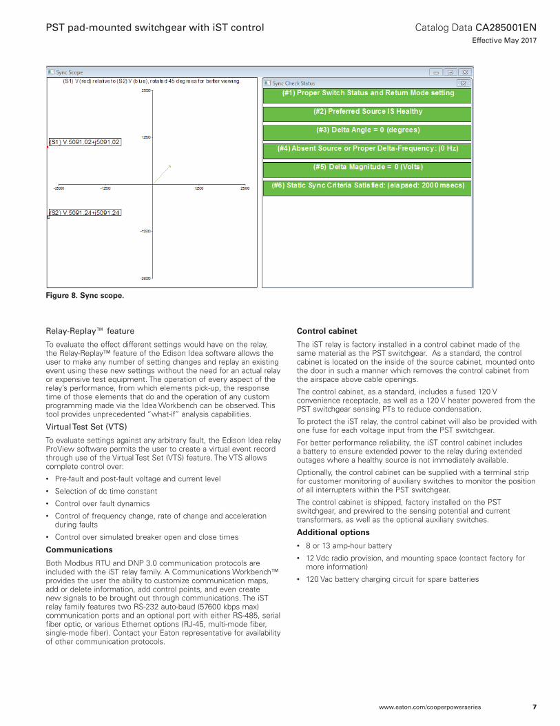
The iST family of relays share the same event records and analysis tools as all Edison Idea relays. The Edison Idea relay allows for the display of event records in a variety of formats including waveforms (oscillography), magnitude plots, phasor diagrams, symmetrical component diagrams and more. ProView, the software for the Edison Idea relay, also provides a unique Application Diagram View that provides a one-screen view of everything that is going on in the relay. Many of these event views are also available in On-Line View mode, where it is possible to monitor the status of the relay in real-time, including phasor diagrams and the Sync Scope, which is ideal for verifying PT and CT phasing during commissioning.
Figure 7. Source 1 and Source 2 phase diagrams.
Figure 6. Current and voltage waveforms.
6
Catalog Data CA285001ENEffective May 2017
PST pad-mounted switchgear with iST control
www.eaton.com/cooperpowerseries
Relay-Replay™ feature
To evaluate the effect different settings would have on the relay, the Relay-Replay™ feature of the Edison Idea software allows the user to make any number of setting changes and replay an existing event using these new settings without the need for an actual relay or expensive test equipment. The operation of every aspect of the relay’s performance, from which elements pick-up, the response time of those elements that do and the operation of any custom programming made via the Idea Workbench can be observed. This tool provides unprecedented “what-if” analysis capabilities.
Virtual Test Set (VTS)
To evaluate settings against any arbitrary fault, the Edison Idea relay ProView software permits the user to create a virtual event record through use of the Virtual Test Set (VTS) feature. The VTS allows complete control over:• Pre-fault and post-fault voltage and current level• Selection of dc time constant• Control over fault dynamics • Control of frequency change, rate of change and acceleration
during faults• Control over simulated breaker open and close times
Communications
Both Modbus RTU and DNP 3.0 communication protocols are included with the iST relay family. A Communications Workbench™ provides the user the ability to customize communication maps, add or delete information, add control points, and even create new signals to be brought out through communications. The iST relay family features two RS-232 auto-baud (57600 kbps max) communication ports and an optional port with either RS-485, serial fiber optic, or various Ethernet options (RJ-45, multi-mode fiber, single-mode fiber). Contact your Eaton representative for availability of other communication protocols.
Control cabinet
The iST relay is factory installed in a control cabinet made of the same material as the PST switchgear. As a standard, the control cabinet is located on the inside of the source cabinet, mounted onto the door in such a manner which removes the control cabinet from the airspace above cable openings.
The control cabinet, as a standard, includes a fused 120 V convenience receptacle, as well as a 120 V heater powered from the PST switchgear sensing PTs to reduce condensation.
To protect the iST relay, the control cabinet will also be provided with one fuse for each voltage input from the PST switchgear.
For better performance reliability, the iST control cabinet includes a battery to ensure extended power to the relay during extended outages where a healthy source is not immediately available.
Optionally, the control cabinet can be supplied with a terminal strip for customer monitoring of auxiliary switches to monitor the position of all interrupters within the PST switchgear.
The control cabinet is shipped, factory installed on the PST switchgear, and prewired to the sensing potential and current transformers, as well as the optional auxiliary switches.
Additional options
• 8 or 13 amp-hour battery• 12 Vdc radio provision, and mounting space (contact factory for
more information)• 120 Vac battery charging circuit for spare batteries
Figure 8. Sync scope.
7
Catalog Data CA285001ENEffective May 2017
PST pad-mounted switchgear with iST control
www.eaton.com/cooperpowerseries
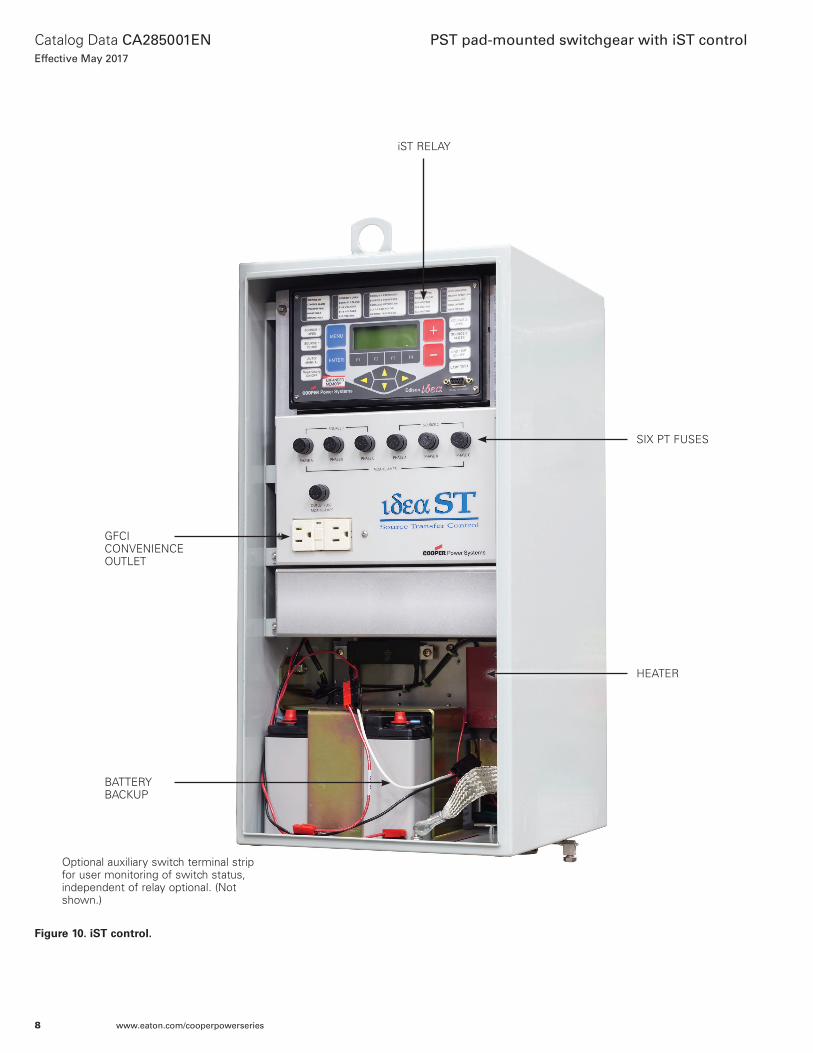
Figure 10. iST control.
iST RELAY
SIx PT FUSES
BATTERY BACkUP
GFCI CONVENIENCE OUTLET
HEATER
Optional auxiliary switch terminal strip for user monitoring of switch status, independent of relay optional. (Not shown.)
8
Catalog Data CA285001ENEffective May 2017
PST pad-mounted switchgear with iST control
www.eaton.com/cooperpowerseries
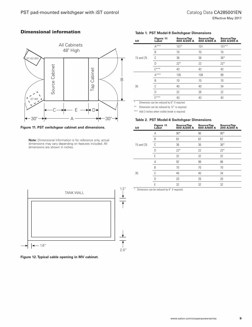
Dimensional information
30" A 30"
DEC
B
Tap
Cab
inet
Sou
rce
Cab
inet
All Cabinets 48" High
Table 2. PST Model-6 Switchgear Dimensions
kVFigure 11 Label
Source/Tap 600 A/200 A
Source/Tap 600 A/600 A
Source/Tap 200 A/200 A
15 and 25
A 90* 90 90*
B 62 62 62
C 36 36 36*
D 22* 22 22*
E 32 32 32
35
A 92 98 86
B 70 70 70
C 40 40 34
D 20 26 20
E 32 32 32
Table 1. PST Model-9 Switchgear Dimensions
kVFigure 11 Label
Source/Tap 600 A/200 A
Source/Tap 600 A/600 A
Source/Tap 200 A/200 A
15 and 25
A*** 101* 101 101**
B 70 70 70
C 36 36 36*
D 22* 22 22*
E*** 43 43 43
35
A*** 105 109 99
B 70 70 70
C 40 40 34
D 22 26 22
E*** 43 43 43
otee:N Dimensional information is for reference only, actual dimensions may vary depending on features included. All dimensions are shown in inches.
iST 621/921
iST 901
Figure 11. PST switchgear cabinet and dimensions.
* Dimension can be reduced by 6” if required.
** Dimension can be reduced by 12” is required.
*** Add 3 inches when visible break is required.
9
Catalog Data CA285001ENEffective May 2017
PST pad-mounted switchgear with iST control
www.eaton.com/cooperpowerseries
* Dimension can be reduced by 6” if required.
Figure 12. Typical cable opening in MV cabinet.
1.3”
2.0”1.6”
TANk WALL
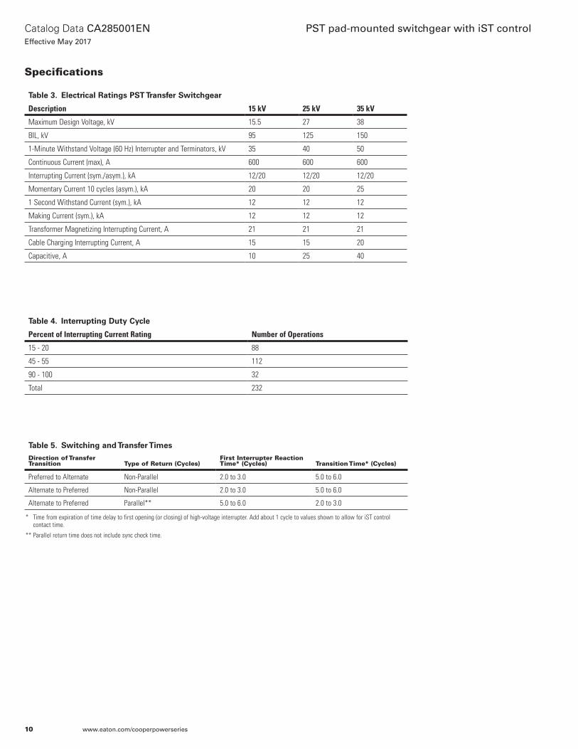
Specifications
Table 3. Electrical Ratings PST Transfer Switchgear
Description 15 kV 25 kV 35 kV
Maximum Design Voltage, kV 15.5 27 38
BIL, kV 95 125 150
1-Minute Withstand Voltage (60 Hz) Interrupter and Terminators, kV 35 40 50
Continuous Current (max), A 600 600 600
Interrupting Current (sym./asym.), kA 12/20 12/20 12/20
Momentary Current 10 cycles (asym.), kA 20 20 25
1 Second Withstand Current (sym.), kA 12 12 12
Making Current (sym.), kA 12 12 12
Transformer Magnetizing Interrupting Current, A 21 21 21
Cable Charging Interrupting Current, A 15 15 20
Capacitive, A 10 25 40
* Time from expiration of time delay to first opening (or closing) of high-voltage interrupter. Add about 1 cycle to values shown to allow for iST control contact time.
** Parallel return time does not include sync check time.
Table 4. Interrupting Duty Cycle
Percent of Interrupting Current Rating Number of Operations
15 - 20 88
45 - 55 112
90 - 100 32
Total 232
Table 5. Switching and Transfer Times
Direction of Transfer Transition Type of Return (Cycles)
First Interrupter Reaction Time* (Cycles) Transition Time* (Cycles)
Preferred to Alternate Non-Parallel 2.0 to 3.0 5.0 to 6.0
Alternate to Preferred Non-Parallel 2.0 to 3.0 5.0 to 6.0
Alternate to Preferred Parallel** 5.0 to 6.0 2.0 to 3.0
10
Catalog Data CA285001ENEffective May 2017
PST pad-mounted switchgear with iST control
www.eaton.com/cooperpowerseries
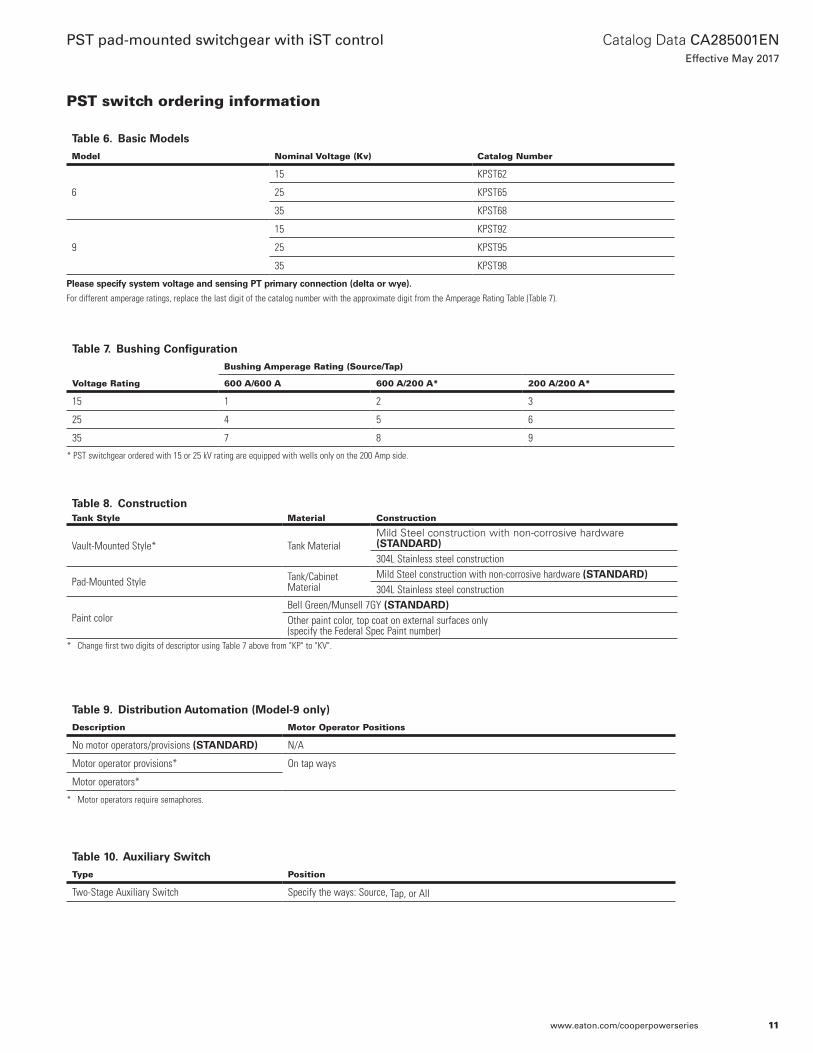
Table 6. Basic Models
Model Nominal Voltage (Kv) Catalog Number
6
15 KPST62
25 KPST65
35 KPST68
9
15 KPST92
25 KPST95
35 KPST98
Table 7. Bushing Configuration
Voltage Rating
Bushing Amperage Rating (Source/Tap)
600 A/600 A 600 A/200 A* 200 A/200 A*
15 1 2 3
25 4 5 6
35 7 8 9
* PST switchgear ordered with 15 or 25 kV rating are equipped with wells only on the 200 Amp side.
Please specify system voltage and sensing PT primary connection (delta or wye).
For different amperage ratings, replace the last digit of the catalog number with the approximate digit from the Amperage Rating Table (Table 7).
PST switch ordering information
Table 10. Auxiliary Switch
Type Position
Two-Stage Auxiliary Switch Specify the ways: Source, Tap, or All
Table 9. Distribution Automation (Model-9 only)
Description Motor Operator Positions
No motor operators/provisions (STANDARD) N/A
Motor operator provisions* On tap ways
Motor operators*
* Motor operators require semaphores.
Table 8. ConstructionTank Style Material Construction
Vault-Mounted Style* Tank MaterialMild Steel construction with non-corrosive hardware (STANDARD)304L Stainless steel construction
Pad-Mounted Style Tank/Cabinet Material
Mild Steel construction with non-corrosive hardware (STANDARD)304L Stainless steel construction
Paint colorBell Green/Munsell 7GY (STANDARD)Other paint color, top coat on external surfaces only (specify the Federal Spec Paint number)
* Change first two digits of descriptor using Table 7 above from "KP" to "KV".
11
Catalog Data CA285001ENEffective May 2017
PST pad-mounted switchgear with iST control
www.eaton.com/cooperpowerseries
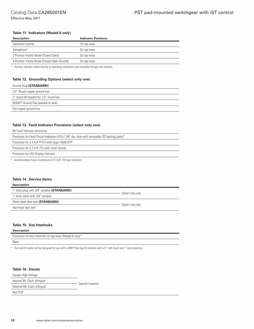
* Position indicator linked directly to operating mechanism and viewable through tank window.
Table 11. Indicators (Model-9 only)
Description Indicator Positions
Operation counter On tap ways
Semaphore* On tap ways
2-Position Visible Break (Closed-Open) On tap ways
3-Position Visible Break (Closed-Open-Ground) On tap ways
Table 16. Decals
Danger High Voltage
Specify LocationInternal Mr. Ouch, bilingual
External Mr. Ouch, bilingual
Non PCB
Table 15. Key Interlocks
Description
Provisions for key interlocks on tap ways (Model-9 only)*
None
Table 14. Service Items
Description
1" drain plug with 3/8" sampler (STANDARD)Select only one
1" drain valve with 3/8" sampler
Penta-head door bolt (STANDARD)Select only one
Hex-head door bolt
Table 13. Fault Indicator Provisions (select only one)
No Fault Indicator provisions
Provisions for Fault Circuit Indicators (FCI) (1.06” dia. hole with removable SS backing plate)*
Provisions for S.T.A.R.™ FCI with large FISHEYE™
Provisions for S.T.A.R. FCI with small remote
Provisions for LED Display Indicator
* Accommodates future installation of S.T.A.R. FCI type indicators
Table 12. Grounding Options (select only one)
Ground Stud (STANDARD)
1/2” Round copper ground-bus
3” stand-off bracket for 1/2” round bus
NEMA® Ground Pad (welded to tank)
Flat copper ground-bus
* The switch handle will be designed for use with a KIRK® Key type B interlock with a ¾” bolt travel and 1” bolt projection.
12
Catalog Data CA285001ENEffective May 2017
PST pad-mounted switchgear with iST control
www.eaton.com/cooperpowerseries
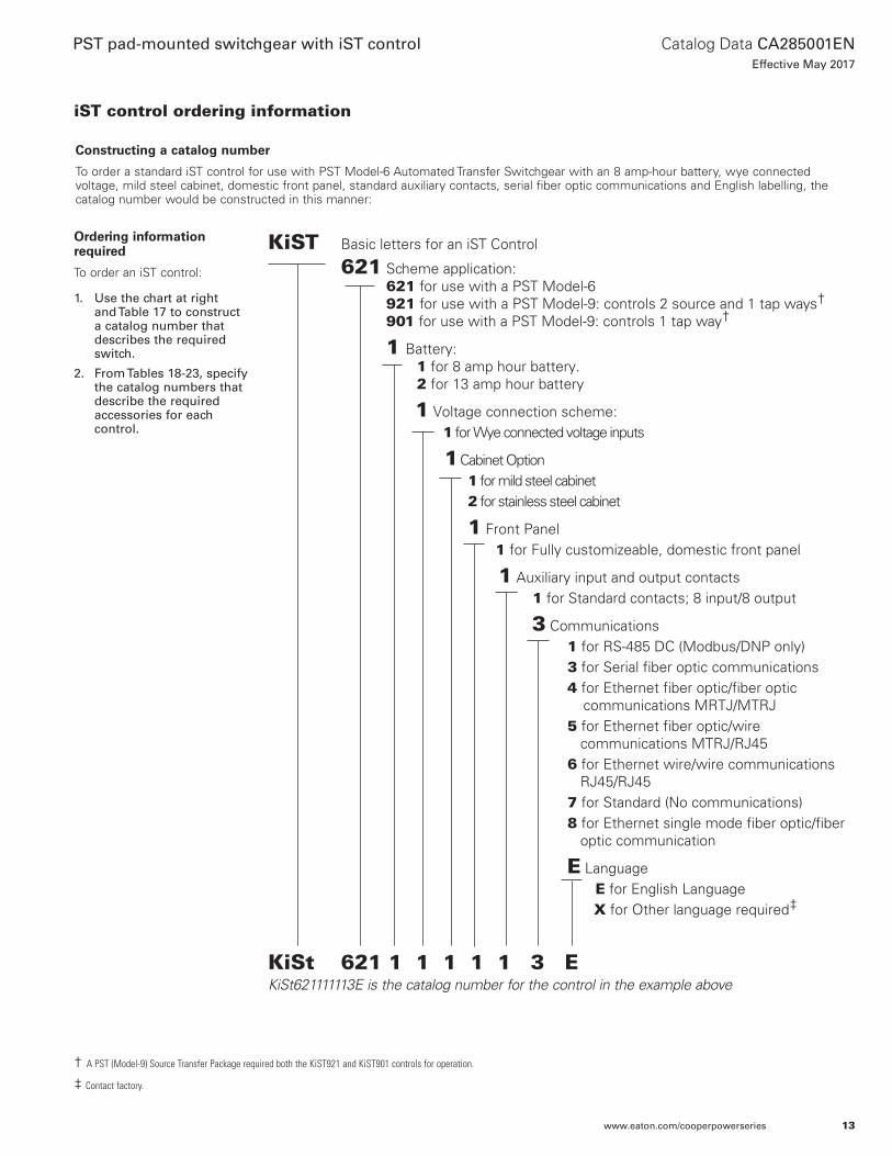
KiST Basic letters for an iST Control
621 Scheme application: 621 for use with a PST Model-6 921 for use with a PST Model-9: controls 2 source and 1 tap ways†
901 for use with a PST Model-9: controls 1 tap way†
1 Battery: 1 for 8 amp hour battery. 2 for 13 amp hour battery
1 Voltage connection scheme: 1 for Wye connected voltage inputs
1 Cabinet Option1 for mild steel cabinet2 for stainless steel cabinet
1 Front Panel1 for Fully customizeable, domestic front panel
1 Auxiliary input and output contacts 1 for Standard contacts; 8 input/8 output
3 Communications1 for RS-485 DC (Modbus/DNP only)3 for Serial fiber optic communications4 for Ethernet fiber optic/fiber optic
communications MRTJ/MTRJ5 for Ethernet fiber optic/wire
communications MTRJ/RJ456 for Ethernet wire/wire communications
RJ45/RJ457 for Standard (No communications)8 for Ethernet single mode fiber optic/fiber
optic communication
E Language E for English Language X for Other language required‡
KiSt 621 1 1 1 1 1 3 EKiSt621111113E is the catalog number for the control in the example above
Constructing a catalog number
To order a standard iST control for use with PST Model-6 Automated Transfer Switchgear with an 8 amp-hour battery, wye connected voltage, mild steel cabinet, domestic front panel, standard auxiliary contacts, serial fiber optic communications and English labelling, the catalog number would be constructed in this manner:
Ordering information required
To order an iST control:
1. Use the chart at right and Table 17 to construct a catalog number that describes the required switch.
2. From Tables 18-23, specify the catalog numbers that describe the required accessories for each control.
† A PST (Model-9) Source Transfer Package required both the KiST921 and KiST901 controls for operation.
‡ Contact factory.
iST control ordering information
13
Catalog Data CA285001ENEffective May 2017
PST pad-mounted switchgear with iST control
www.eaton.com/cooperpowerseries
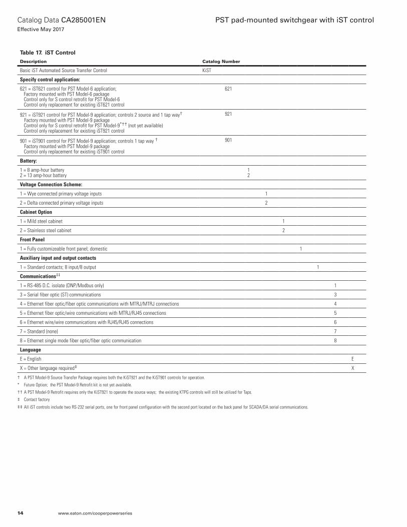
Table 17. iST Control
Description Catalog Number
Basic iST Automated Source Transfer Control KiST
Specify control application:
621 = iST621 control for PST Model-6 application; Factory mounted with PST Model-6 package Control only for S control retrofit for PST Model-6 Control only replacement for existing iST621 control
621
921 = iST921 control for PST Model-9 application; controls 2 source and 1 tap way† Factory mounted with PST Model-9 package Control only for S control retrofit for PST Model-9*†† (not yet available) Control only replacement for existing iST921 control
921
901 = iST901 control for PST Model-9 application; controls 1 tap way † Factory mounted with PST Model-9 package Control only replacement for existing iST901 control
901
Battery:
1 = 8 amp-hour battery2 = 13 amp-hour battery
12
Voltage Connection Scheme:
1 = Wye connected primary voltage inputs 1
2 = Delta connected primary voltage inputs 2
Cabinet Option
1 = Mild steel cabinet 1
2 = Stainless steel cabinet 2
Front Panel
1 = Fully customizeable front panel; domestic 1
Auxiliary input and output contacts
1 = Standard contacts; 8 input/8 output 1
Communications‡‡
1 = RS-485 D.C. isolate (DNP/Modbus only) 1
3 = Serial fiber optic (ST) communications 3
4 = Ethernet fiber optic/fiber optic communications with MTRJ/MTRJ connections 4
5 = Ethernet fiber optic/wire communications with MTRJ/RJ45 connections 5
6 = Ethernet wire/wire communications with RJ45/RJ45 connections 6
7 = Standard (none) 7
8 = Ethernet single mode fiber optic/fiber optic communication 8
Language
E = English E
X = Other language required‡ X
† A PST Model-9 Source Transfer Package requires both the KiST921 and the KiST901 controls for operation.
* Future Option; the PST Model-9 Retrofit kit is not yet available.
†† A PST Model-9 Retrofit requires only the KiST921 to operate the source ways; the existing KTPG controls will still be utilized for Taps.
‡ Contact factory
‡‡ All iST controls include two RS-232 serial ports, one for front panel configuration with the second port located on the back panel for SCADA/DA serial communications.
14
Catalog Data CA285001ENEffective May 2017
PST pad-mounted switchgear with iST control
www.eaton.com/cooperpowerseries

Accessories
Table 18. Auxiliary Switch Termination*†
Description Catalog Number
Auxiliary switch receptacle and wiring KiST-1801-2
* For connecting customer specified, additional A&B Auxiliary Switch contacts from the PST switchgear.
† For use only with the KiST621 and KiST921 controls.
Table 19. Convenience Outlet
Description Catalog Number
Fused 120 Vac, 3-wire polarized GFCI convenience outlet KiST-2970-1
Table 20. Automation Packages
Description Catalog Number
Full automation accessory; 12 Vdc radio provision (Radio and fiber-optic/RS232 interface not included)
KiST-3770-1
Table 21. Communication Support Equipment
Description Catalog Number
RS-232 cable, 6-ft., DB-9F and DB-9M, for direct connection between DATA PORT and PC
KME5-66
DB-9F to DB-25M Cable, 6 feet length KP2412A3
Table 22. Cables
Description Catalog Number
KiST921 Cables for S Control Retrofit; PST Model-9 TBD - FUTURE
Table 23. Miscellaneous Accessories
Description Catalog Number
120 Vac Battery charger for spare batteries KME5-60-1
15
Catalog Data CA285001ENEffective May 2017
PST pad-mounted switchgear with iST control
www.eaton.com/cooperpowerseries
iST CONTROL
TOiST
CONTROL
TOiST
CONTROL
TOiST
CONTROL
PTs PTsC.T.
ControlControlPTs PTs
Figure 14. PST Model-9 switchgear diagram.
Figure 13. PST Model-6 switchgear diagram.
PST pad-mounted switchgear with iST control
Eaton1000 Eaton BoulevardCleveland, OH 44122United StatesEaton.com
Eaton’s Power Systems Division2300 Badger DriveWaukesha, WI 53188United StatesEaton.com/cooperpowerseries
© 2017 EatonAll Rights ReservedPrinted in USAPublication No. CA285001EN
Catalog Data CA285001ENEffective May 2017
For Eaton’s Cooper Power series product information call 1-877-277-4636 or visit: www.eaton.com/cooperpowerseries.
Eaton is a registered trademark.
All other trademarks are property of their respective owners.


![SAN]OSE CITYOF MemorandumFeeder from Switchgear M5 to Switchgear S16B 6. Feeder from Switchgear M5 to Switchgear ESB Engineer'sEstimate $384,787 $77,720 $211,326 $747,139 ... Ifthisproject](https://static.fdocuments.net/doc/165x107/5e7fcbe33356ee7623111eaf/sanose-cityof-feeder-from-switchgear-m5-to-switchgear-s16b-6-feeder-from-switchgear.jpg)