CA NLH 037 NLH 2016 Capital Budget Application Page 1 … · NLH 2016 Capital Budget Application...
23
CA‐NLH‐037 NLH 2016 Capital Budget Application Page 1 of 1 Q. Volume III, Tab 19 – Replace Protective Relays 1 Please provide a copy of the “draft transformer standard” prepared by Hydro in 2 2014. 3 4 5 A. Please see CA‐NLH‐037 Attachment 1. 6
Transcript of CA NLH 037 NLH 2016 Capital Budget Application Page 1 … · NLH 2016 Capital Budget Application...
CA‐NLH‐037 NLH 2016 Capital Budget Application
Page 1 of 1
Q. Volume III, Tab 19 – Replace Protective Relays 1
Please provide a copy of the “draft transformer standard” prepared by Hydro in 2
2014. 3
4
5
A. Please see CA‐NLH‐037 Attachment 1. 6
Page 1 of 18
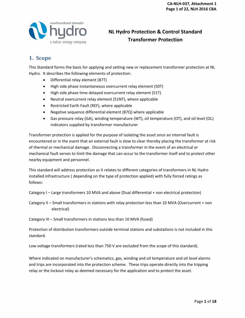
NL Hydro Protection & Control Standard
Transformer Protection
1. Scope
This Standard forms the basis for applying and setting new or replacement transformer protection at NL
Hydro. It describes the following elements of protection:
Differential relay element (87T)
High side phase instantaneous overcurrent relay element (50T)
High side phase time delayed overcurrent relay element (51T)
Neutral overcurrent relay element (51NT), where applicable
Restricted Earth Fault (REF), where applicable
Negative sequence differential element (87Q) where applicable
Gas pressure relay (GA), winding temperature (WT), oil temperature (OT), and oil level (OL)
indicators supplied by transformer manufacturer
Transformer protection is applied for the purpose of isolating the asset once an internal fault is
encountered or in the event that an external fault is slow to clear thereby placing the transformer at risk
of thermal or mechanical damage. Disconnecting a transformer in the event of an electrical or
mechanical fault serves to limit the damage that can occur to the transformer itself and to protect other
nearby equipment and personnel.
This standard will address protection as it relates to different categories of transformers in NL Hydro
installed infrastructure ( depending on the type of protection applied) with fully forced ratings as
follows:
Category I – Large transformers 10 MVA and above (Dual differential + non electrical protection)
Category II – Small transformers in stations with relay protection less than 10 MVA (Overcurrent + non
electrical)
Category III – Small transformers in stations less than 10 MVA (fused)
Protection of distribution transformers outside terminal stations and substations is not included in this
standard.
Low voltage transformers (rated less than 750 V are excluded from the scope of this standard).
Where indicated on manufacturer’s schematics, gas, winding and oil temperature and oil level alarms
and trips are incorporated into the protection scheme. These trips operate directly into the tripping
relay or the lockout relay as deemed necessary for the application and to protect the asset.
CA-NLH-037, Attachment 1 Page 1 of 22, NLH 2016 CBA
Page 2 of 18
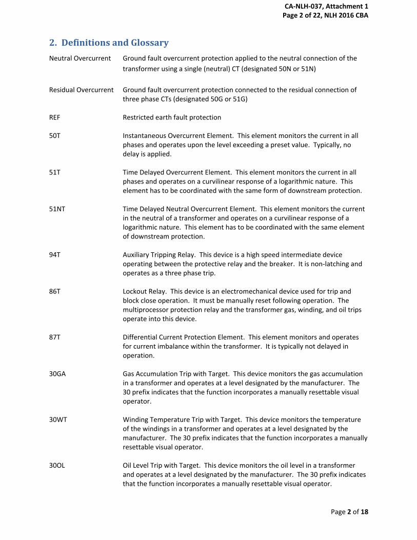
2. Definitions and Glossary
Neutral Overcurrent Ground fault overcurrent protection applied to the neutral connection of the
transformer using a single (neutral) CT (designated 50N or 51N)
Residual Overcurrent Ground fault overcurrent protection connected to the residual connection of three phase CTs (designated 50G or 51G)
REF Restricted earth fault protection 50T Instantaneous Overcurrent Element. This element monitors the current in all
phases and operates upon the level exceeding a preset value. Typically, no delay is applied.
51T Time Delayed Overcurrent Element. This element monitors the current in all
phases and operates on a curvilinear response of a logarithmic nature. This element has to be coordinated with the same form of downstream protection.
51NT Time Delayed Neutral Overcurrent Element. This element monitors the current
in the neutral of a transformer and operates on a curvilinear response of a logarithmic nature. This element has to be coordinated with the same element of downstream protection.
94T Auxiliary Tripping Relay. This device is a high speed intermediate device
operating between the protective relay and the breaker. It is non-latching and operates as a three phase trip.
86T Lockout Relay. This device is an electromechanical device used for trip and
block close operation. It must be manually reset following operation. The multiprocessor protection relay and the transformer gas, winding, and oil trips operate into this device.
87T Differential Current Protection Element. This element monitors and operates
for current imbalance within the transformer. It is typically not delayed in operation.
30GA Gas Accumulation Trip with Target. This device monitors the gas accumulation
in a transformer and operates at a level designated by the manufacturer. The 30 prefix indicates that the function incorporates a manually resettable visual operator.
30WT Winding Temperature Trip with Target. This device monitors the temperature
of the windings in a transformer and operates at a level designated by the manufacturer. The 30 prefix indicates that the function incorporates a manually resettable visual operator.
30OL Oil Level Trip with Target. This device monitors the oil level in a transformer
and operates at a level designated by the manufacturer. The 30 prefix indicates that the function incorporates a manually resettable visual operator.
CA-NLH-037, Attachment 1 Page 2 of 22, NLH 2016 CBA
Page 3 of 18
30OT Oil Temperature Trip with Target. This device monitors the oil temperature in a
transformer and operates at a level designated by the manufacturer. The 30 prefix indicates that the function incorporates a manually resettable visual operator.
CT Current Transformer.
3. Normative Reference Papers
IEEE/ANSI C37.2 ANSI Standard for Electrical Power System Device Function Numbers, Acronyms
and Contact Designations.
IEEE Std C37.91-2000 IEEE Guide for Protective Relay Applications to Power Transformers
IEEE Std C37.110 IEEE Guide for the Application of Current Transformers Used for Protective
Relaying Purposes
IEEE Std C57.109 IEEE Guide for Liquid-Immersed Transformers Through-Fault-Current Duration
4. Protection Requirements
4.1 Category I – Large Transformers 10 MVA and above
Transformers in this category are generally found in large to medium scale transmission terminal
stations. To protect these transformers, two microprocessor based protection relays are to be used
from separate manufacturers. These relays are utilized in two functionally equivalent schemes
(Protection A and Protection B) with the exception of non-electrical protective devices. Transformer
protection requires connection of the relay to CTs on high and low sides of the transformer.
The following functions shall be applied in both A and B protections:
• Restrained and unrestrained differential protection
• Phase time and instantaneous overcurrent (on the high voltage side only)
• Neutral and/or residual time overcurrent (on both high and low voltage sides).
Tertiary zero sequence overcurrent (where CTs are provided inside the tertiary)
• REF shall be applied only in cases where neutral grounding impedances are applied that limit
fault current to less than transformer rated current.
Non-electrical protection functions are not redundant, and shall be applied normally as part of the A
protection system with automatic transfer to the B protection in the event of loss of power to the A
protection.
CA-NLH-037, Attachment 1 Page 3 of 22, NLH 2016 CBA
Page 4 of 18
Negative sequence differential protection exists in the SEL protective relays only and may be considered
for future application in the A protection only.
In special cases (for example two LV windings) LV phase overcurrent protection might be applied instead
of, or in addition to HV phase overcurrent protection.
4.1.1 CT connection and ratio selection
For legacy electromechanical protection systems, CTs usually required wye or delta connections to
relays to account for phase shift across the transformer. However, since phase angle and current
amplitude compensation can be made in the settings of microprocessor based relays, phase CTs used for
protection systems specified in this standard will all be wye connected to the relays. Connecting CTs in
wye configurations allow for residual current to be measured where required. The wye configuration
also allows phase currents to be recorded by the protective relay, thereby facilitating disturbance
analysis. CTs inside a tertiary delta shall be connected single phase to the 51N Tertiary element to
measure zero sequence current (I0) if there is no load on the tertiary winding. If there is load connected
to the tertiary, three CTs inside the delta shall be connected in parallel to remove the external load
component and measure 3 times the zero sequence current. Note that the single tertiary CT will be
shared by the 51N tertiary overcurrent function in both the A and B protection systems.
Where a sufficient number of CTs are available, Protection A relay is to use the furthest CTs out from
transformer including the breaker where applicable and the Protection B relay is to use the next CT set
inward. The relay settings are applied in the same way to both relays, therefore both relays should
operate simultaneously for any given fault. In cases where sufficient CTs are not available for dedication
to both the A and B protection systems, they may share a set of CTs as long as adequate test and
isolation facilities are provided to allow either protection system to be taken out of service while the
other remains in service.
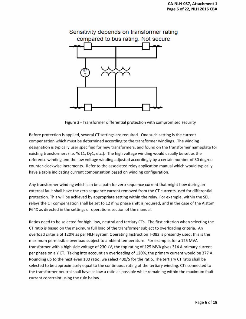
A dedicated restraint input is desired from each CT that closes off the differential zone, to aid in fault
analysis as shown in Figure 1 or Figure 2. CTs that are measuring currents from fault current sources
shall never be summed external to the relay (as shown in Figure 3) since each CT must provide its own
restraint current to the relay. However, CTs that are serving only loads may be summed if there are not
sufficient restraint inputs available on the differential relay.
CA-NLH-037, Attachment 1 Page 4 of 22, NLH 2016 CBA

Page 5 of 18
Figure 1 - Optimum application of transformer protection
Figure 2 - Transformer differential protection with possible reduced sensitivity
CA-NLH-037, Attachment 1 Page 5 of 22, NLH 2016 CBA
Page 6 of 18
Figure 3 - Transformer differential protection with compromised security
Before protection is applied, several CT settings are required. One such setting is the current
compensation which must be determined according to the transformer windings. The winding
designation is typically user specified for new transformers, and found on the transformer nameplate for
existing transformers (i.e. Yd11, Dy1, etc.). The high voltage winding would usually be set as the
reference winding and the low voltage winding adjusted accordingly by a certain number of 30 degree
counter-clockwise increments. Refer to the associated relay application manual which would typically
have a table indicating current compensation based on winding configuration.
Any transformer winding which can be a path for zero sequence current that might flow during an
external fault shall have the zero sequence current removed from the CT currents used for differential
protection. This will be achieved by appropriate setting within the relay. For example, within the SEL
relays the CT compensation shall be set to 12 if no phase shift is required, and in the case of the Alstom
P64X as directed in the settings or operations section of the manual.
Ratios need to be selected for high, low, neutral and tertiary CTs. The first criterion when selecting the
CT ratio is based on the maximum full load of the transformer subject to overloading criteria. An
overload criteria of 120% as per NLH System Operating Instruction T-082 is presently used; this is the
maximum permissible overload subject to ambient temperature. For example, for a 125 MVA
transformer with a high side voltage of 230 kV, the top rating of 125 MVA gives 314 A primary current
per phase on a Y CT. Taking into account an overloading of 120%, the primary current would be 377 A.
Rounding up to the next even 100 ratio, we select 400/5 for the ratio. The tertiary CT ratio shall be
selected to be approximately equal to the continuous rating of the tertiary winding. CTs connected to
the transformer neutral shall have as low a ratio as possible while remaining within the maximum fault
current constraint using the rule below.
CA-NLH-037, Attachment 1 Page 6 of 22, NLH 2016 CBA
Page 7 of 18
The maximum internal fault current should not exceed 20 * INOM (where INOM is 5A) = 100A for the
selected ratio for both the main winding and tertiary and neutral CTs. This is required for high and low
voltage and tertiary windings and neutral CTs. This is the second of the two criteria for selecting CT
ratios.
In instances where there are two breakers on the high or low side of the transformer, the CT rating is
subject to bus load. The breaker CTs will be rated to accommodate bus loads, not necessarily the
transformer maximum load and therefore will require a high ratio. It should be noted that this can
impact sensitivity of the protection. In cases where the transformer protection sensitivity requirements
noted in Section 4.1.2 cannot be met, if transformer bushing CT’s are available, the bus zone shall be
provided with its own differential protection using high ratio CTs and the transformer differential
protection shall be connected to lower ratio bushing CTs as shown in Figure 1. If sufficient CTs are not
available to provide dedicated transformer protection with desired sensitivity, then the differential
protection shall be connected as shown in Figure 2, and the best achievable sensitivity using bus CTs will
have to be accepted.
CTs need to be rated so that they do not saturate during normal transformer loading. CT saturation,
which often occurs during faults, can lead to misoperation of relays but transformer differential
protection relays are designed to discern saturation from actual faults.
CTs are selected so that their normal operation is in the linear region of their curve. The CT’s burden
consists of the accumulated resistances from the secondary devices and cabling (i.e. relays, meters,
conductors, etc.). The CT secondary current multiplied by the applied burden results in a voltage across
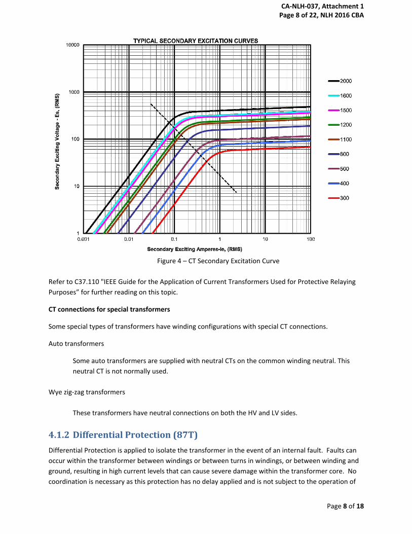
the CT secondary terminals. An example of a CT secondary excitation curve for a bushing CT in a 230kV
breaker is provided in Figure 4. CT saturation occurs when the excitation current becomes nonlinear as
indicated by being above the dashed line in Figure 4.
CA-NLH-037, Attachment 1 Page 7 of 22, NLH 2016 CBA
Page 8 of 18
Figure 4 – CT Secondary Excitation Curve
Refer to C37.110 "IEEE Guide for the Application of Current Transformers Used for Protective Relaying
Purposes” for further reading on this topic.
CT connections for special transformers
Some special types of transformers have winding configurations with special CT connections.
Auto transformers
Some auto transformers are supplied with neutral CTs on the common winding neutral. This
neutral CT is not normally used.
Wye zig-zag transformers
These transformers have neutral connections on both the HV and LV sides.
4.1.2 Differential Protection (87T)
Differential Protection is applied to isolate the transformer in the event of an internal fault. Faults can
occur within the transformer between windings or between turns in windings, or between winding and
ground, resulting in high current levels that can cause severe damage within the transformer core. No
coordination is necessary as this protection has no delay applied and is not subject to the operation of
CA-NLH-037, Attachment 1 Page 8 of 22, NLH 2016 CBA
Page 9 of 18
other upstream or downstream protection devices. Both A and B protection systems use restrained and
unrestrained current differential protection elements. The commonly used restrained element uses a
dual slope, variable percentage characteristic which provides more sensitive and secure protection as
well as compensates for CT ratio mismatches, CT ratio errors, CT saturation, and errors caused by tap
changing. Some relays (for example SEL 487E) may use a single (sensitive) slope combined with external
fault detection and/or CT saturation detection that switches to a less sensitive slope for external faults.
The unrestrained element provides for protection against high current faults which might produce CT
saturation that prevents the restrained element from operating.
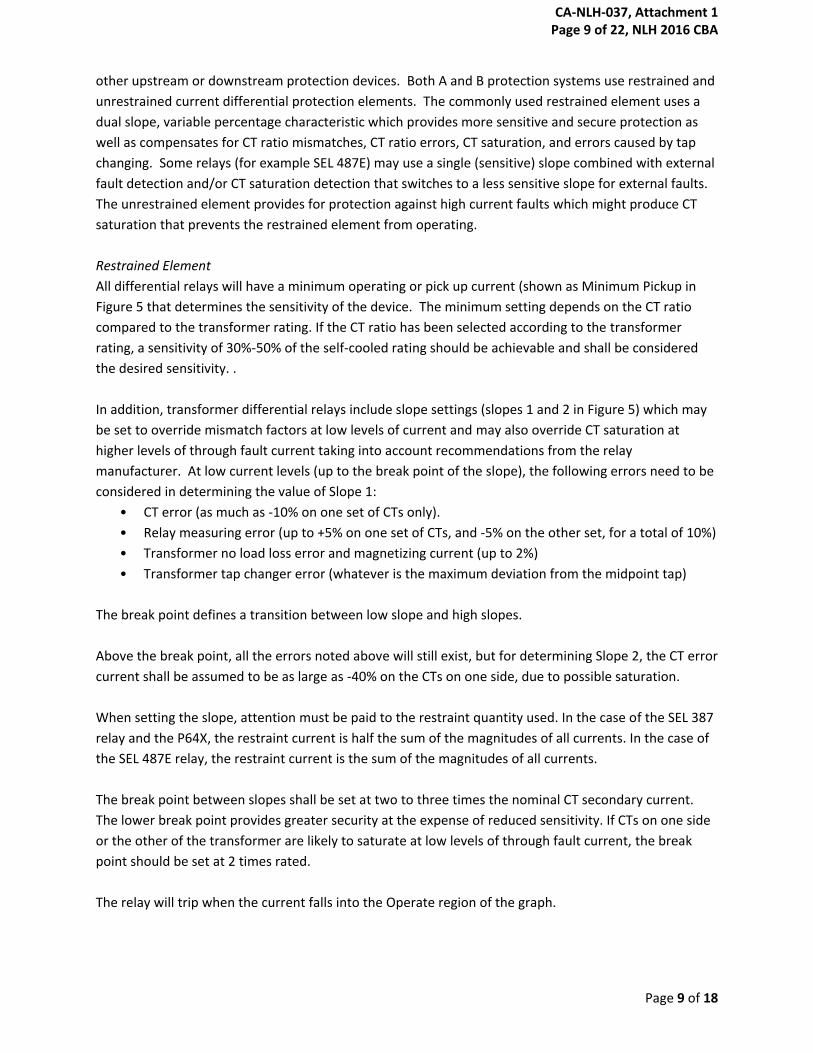
Restrained Element
All differential relays will have a minimum operating or pick up current (shown as Minimum Pickup in
Figure 5 that determines the sensitivity of the device. The minimum setting depends on the CT ratio
compared to the transformer rating. If the CT ratio has been selected according to the transformer
rating, a sensitivity of 30%-50% of the self-cooled rating should be achievable and shall be considered
the desired sensitivity. .
In addition, transformer differential relays include slope settings (slopes 1 and 2 in Figure 5) which may
be set to override mismatch factors at low levels of current and may also override CT saturation at
higher levels of through fault current taking into account recommendations from the relay
manufacturer. At low current levels (up to the break point of the slope), the following errors need to be
considered in determining the value of Slope 1:
• CT error (as much as -10% on one set of CTs only).
• Relay measuring error (up to +5% on one set of CTs, and -5% on the other set, for a total of 10%)
• Transformer no load loss error and magnetizing current (up to 2%)
• Transformer tap changer error (whatever is the maximum deviation from the midpoint tap)
The break point defines a transition between low slope and high slopes.
Above the break point, all the errors noted above will still exist, but for determining Slope 2, the CT error
current shall be assumed to be as large as -40% on the CTs on one side, due to possible saturation.
When setting the slope, attention must be paid to the restraint quantity used. In the case of the SEL 387
relay and the P64X, the restraint current is half the sum of the magnitudes of all currents. In the case of
the SEL 487E relay, the restraint current is the sum of the magnitudes of all currents.
The break point between slopes shall be set at two to three times the nominal CT secondary current.
The lower break point provides greater security at the expense of reduced sensitivity. If CTs on one side
or the other of the transformer are likely to saturate at low levels of through fault current, the break
point should be set at 2 times rated.
The relay will trip when the current falls into the Operate region of the graph.
CA-NLH-037, Attachment 1 Page 9 of 22, NLH 2016 CBA
Page 10 of 18
Figure 5 – Dual Slope Characteristic
When a transformer is energized, an inrush of current occurs that is seen by the high voltage terminals
but not immediately by the low voltage terminals. This can be seen by the relay as a fault. During
inrush of a transformer, there are significant 2nd and 4th harmonic content in the current. During
overexcitation of a transformer, there is significant 5th harmonic content in the current. These
harmonics can be used to discriminate between inrush and overexcitation conditions and fault
conditions. Harmonic blocking and/or restraint are/is used for situations of inrush and overexcitation
conditions. Values for blocking elements are based on historical evidence of transformer
measurements.
Inrush suppression settings are based on industry historical knowledge. The industry standard level of
15% 2nd harmonic (and 4th harmonic if available) will be used unless experience determines that a lower
level is required. In addition harmonic blocking with cross blocking will be applied to ensure that
harmonic presence in any phase will block all phases. Note that for SEL387 relays, the term “non-
independent” blocking is used to signify cross blocking. The differential element can operate due to
inrush and overexcitation, therefore using harmonic blocking is valuable in the prevention of relay
misoperation during these situations.
If available, an extra element sensing 5th harmonic at a value of 35% persisting for longer than 30 cycles
may be used to trigger an event record.
0
1
2
3
4
5
6
7
0 2 4 6 8 10 12
Ioperate (pu)
Irestraint (pu)
Operate Region
Restraint Region Minimum Pick up
Slope 1 Slope 2
Break Point
CA-NLH-037, Attachment 1 Page 10 of 22, NLH 2016 CBA
Page 11 of 18
Unrestrained Element
The unrestrained element responds to fundamental frequency only, therefore harmonic blocking does
not apply. It will provide dependable protection in the event of CT saturation for high magnitude
internal faults that could produce harmonics and block the more sensitive restrained element. A
conservative setting is 1/Zt (in per unit of the naturally cooled rating of the transformer) where Zt is the
transformer impedance in per unit. The setting must be lower than the maximum high side 3-phase
fault current and current resulting from CT saturation but higher than the maximum inrush current.
4.1.3 Overcurrent Protection
Overcurrent protection is applied on the transformer high side to protect the transformer from internal
faults. The selections of overcurrent instantaneous and time-delayed values are made based on load
and fault levels from System Planning studies and coordinated with low side protection settings and
transformer damage curve.
50T - Instantaneous Phase Overcurrent
Instantaneous Overcurrent protection is used to clear internal faults as fast as possible. NL Hydro
standard setting is 130% of maximum 3-phase low side fault level. It is noted that this element will be
less sensitive than the unrestrained differential element, and adds little value to the transformer
protection. It is provided for historical reasons only. It also facilitates plotting overcurrent relay
characteristics for checking coordination.
51T - Phase Time Overcurrent
Phase Time Overcurrent protection is used to protect the transformer from slow clearing faults outside
the protection zone of the transformer. There are various types of time overcurrent curves that can be
applied. IEEE and US curves consist of moderately inverse, inverse, very inverse, extremely inverse, and
short time inverse. IEC curves consist of standard inverse, very inverse, extremely inverse, short time
inverse, and long time inverse. The 51T curve has to be coordinated between the transformer damage
curve and the low side 51T curve(s). Standard damage curves can be found in the IEEE Standard
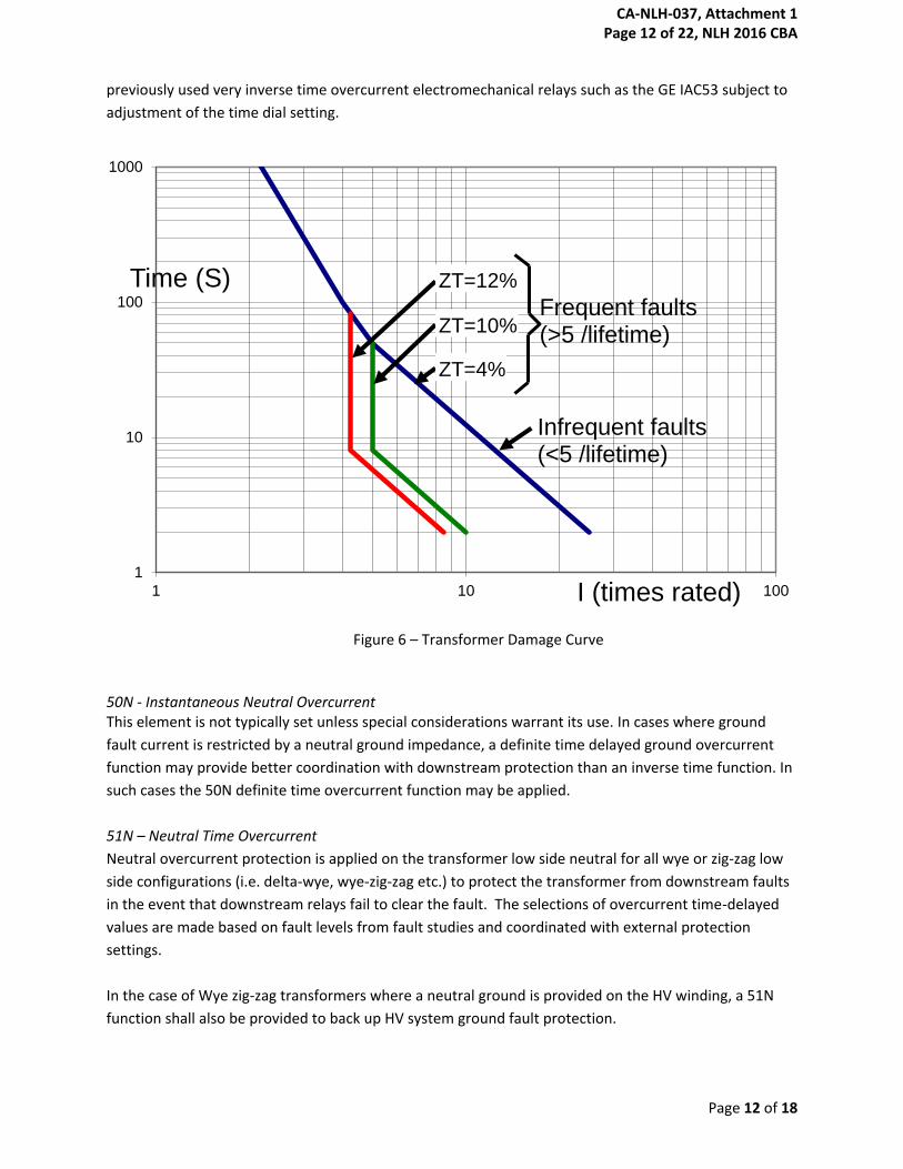
C57.109 (see section 3 – Normative Reference Papers) and an example curve is shown in Figure 6.
Transformer impedance is required in order to select appropriate damage curve. For existing
transformers, this value can be obtained from the nameplate of the transformer. For new transformers,
this value can be obtained from the purchase specification and/or factory test results. Relay
coordination software such as Aspen One-Liner has standard damage curves built in to the relay
coordination function.
The time current characteristic must also be secure against undesirable tripping due to magnetizing
inrush. ASPEN OneLiner provides a conservative estimate of the inrush current that should be used to
ensure the 51T function will be secure during energization.
The pickup value will be 150% of the maximum rating of the transformer unless other factors (such as
cold load inrush) dictate a higher setting. The curve to be selected must be evaluated against those of
immediate downstream protection. Typically, a very inverse curve (IEEE / US) would be used as
provided in the microprocessor based relay manual. This curve closely matches the response of
CA-NLH-037, Attachment 1 Page 11 of 22, NLH 2016 CBA
Page 12 of 18
previously used very inverse time overcurrent electromechanical relays such as the GE IAC53 subject to
adjustment of the time dial setting.
Figure 6 – Transformer Damage Curve
50N - Instantaneous Neutral Overcurrent This element is not typically set unless special considerations warrant its use. In cases where ground
fault current is restricted by a neutral ground impedance, a definite time delayed ground overcurrent
function may provide better coordination with downstream protection than an inverse time function. In
such cases the 50N definite time overcurrent function may be applied.
51N – Neutral Time Overcurrent
Neutral overcurrent protection is applied on the transformer low side neutral for all wye or zig-zag low
side configurations (i.e. delta-wye, wye-zig-zag etc.) to protect the transformer from downstream faults
in the event that downstream relays fail to clear the fault. The selections of overcurrent time-delayed
values are made based on fault levels from fault studies and coordinated with external protection
settings.
In the case of Wye zig-zag transformers where a neutral ground is provided on the HV winding, a 51N
function shall also be provided to back up HV system ground fault protection.
1
10
100
1000
1 10 100
Time (S)
I (times rated)
Infrequent faults (<5 /lifetime)
Frequent faults (>5 /lifetime)
ZT=12%
ZT=10%
ZT=4%
CA-NLH-037, Attachment 1 Page 12 of 22, NLH 2016 CBA
Page 13 of 18
The pick-up value and curve to be selected must be evaluated against those of immediate downstream
protection. Typically, an inverse curve would be used. This curve matches closely the response of
previously used inverse time overcurrent electromechanical relays such as the GE IAC51 subject to
adjustment of the time dial setting.
50G – Instantaneous Residual Overcurrent
Residual overcurrent protection will provide fast and sensitive protection to delta connected
transformer windings connected to the transmission system. Since it need not coordinate with any other
devices, the only limitation on sensitivity is that it shall not operate in the case of CT saturation during
energization (inrush) or during external faults on the other side of the transformer. A pickup setting of
twice the transformer fully forced rated current will normally override these transient conditions.
51G Residual Time Overcurrent
Residual time overcurrent will provide more sensitive protection (than the 50G function) to delta
connected transformer windings connected to the transmission system. The time delay will allow it to
override transient CT saturation. A pickup setting of 25% of the transformer fully forced rated current
with a very inverse time current characteristic and a time dial of 3 will normally override the transient CT
saturation.
REF protection allows increased sensitivity for transformer protection in cases where ground fault
currents are significantly lower than multiphase fault currents due to the addition of neutral grounding
impedances. REF protection shall be included in the A and B protection systems in such cases.
4.1.4 Non-Electrical Protection
The non-electrical protection devices consist of those inherent to the design of the transformer as
specified in the NL Hydro purchase specification or as supplied by the transformer manufacturer.
Dry contacts are provided from the transformer for each of the above elements as a minimum. Some
elements are repeated for load tap changer oil conservator and additional windings. For new
transformers, refer to the manufacturer’s drawings to implement trip contacts.
The non-electrical protection normally trips through the A protection system. However since
functionally equivalent redundant protection systems are provided, it is anticipated that the transformer
could remain in service while the A protection is removed from service (for test or modification) for a
significant period of time. Since NL Hydro’s policy is to not allow the transformer to be operated for any
length of time with the non-electrical protection being out of service, facilities shall be provided to
switch the non-electrical protection to the B protection system automatically if power to the A
protection system is lost.
4.1.5 Tripping and Isolation
All tripping for internal faults will operate into a lockout relay (86T one for each of A and B protections).
The lockout relay will trip breaker(s), block close of tripped breakers and open of motor operated
CA-NLH-037, Attachment 1 Page 13 of 22, NLH 2016 CBA
Page 14 of 18
disconnects for complete isolation of the faulted transformer. Once the faulted transformer has been
isolated by disconnect switches (where applicable) close blocking and continuous tripping of circuit
breakers that can no longer energize the faulted transformer will be removed. Close blocking of the
isolating switches will be retained until the lockout relay has been reset.
Tripping by most time overcurrent elements including the tertiary overcurrent element is expected for
external faults or severe overload conditions only. Tripping by these elements will be non-lockout (94T)
and with no automatic isolation. The exception will be tripping by the residual time overcurrent element
when it is protecting a transformer delta winding. Operation of this element will only occur for an
internal transformer fault.
All tripping will initiate breaker failure protection of transformers that can energize the fault.
4.1.6 NLH Standards of Acceptance for Transformer Protection Devices
Microprocessor Protection Relays
Standard two winding
Protection A: SEL-387E
Protection B: Alstom P643
Three winding (or special purpose application) without station service tertiary
Protection A: SEL-487E
Protection B: Alstom P643, P645
Auxiliary Relays
Tripping (94, 94X): ABB RXMS1
Flag Indicators (30): ABB RXSF1
Lockout (86): Electroswitch LOR
GE HEA61C
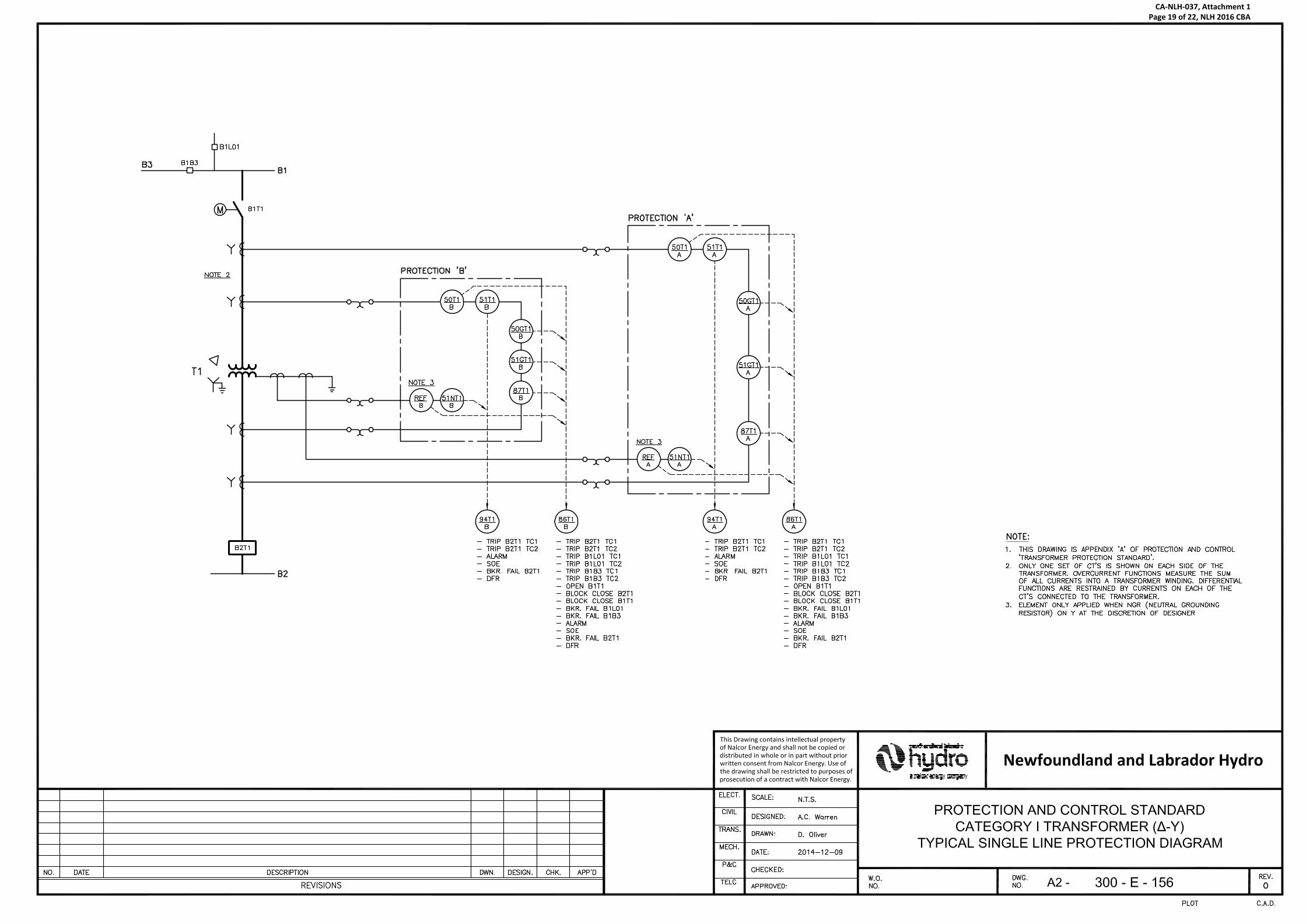
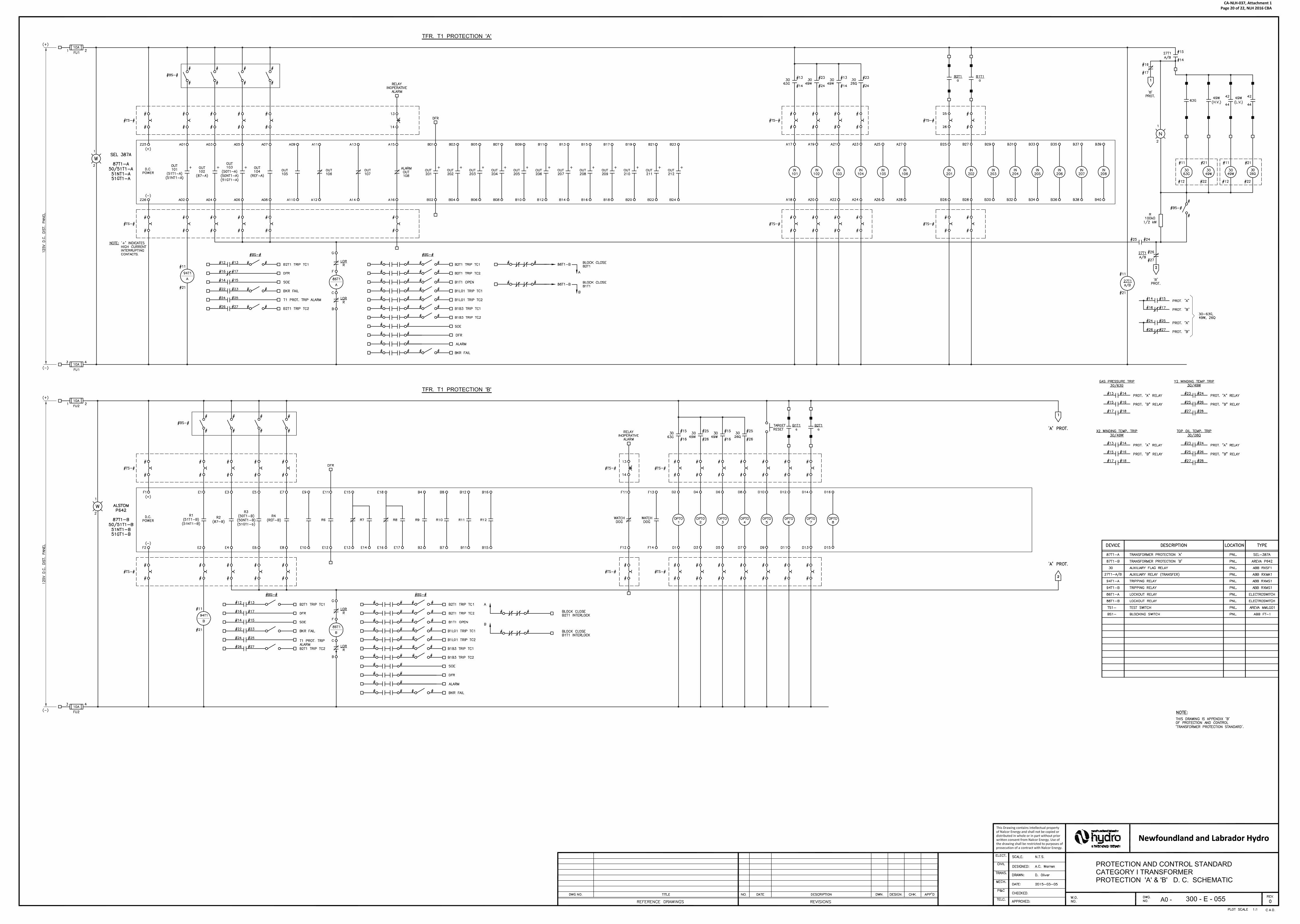
4.1.7 Schematic Development
A typical Single Line Protection Schematic (A and B scheme), as used by NL Hydro for a Category I
transformer, is provided in Appendix A. A typical Protection DC Schematic (A and B scheme), as used by
NL Hydro for a 230kV transformer, is provided in Appendix B. These schemes are used on transformers
having an MVA rating of 10 MVA and higher.
CA-NLH-037, Attachment 1 Page 14 of 22, NLH 2016 CBA

Page 15 of 18
4.2 Category II – Small transformers in stations with relay protection
less than 10 MVA (Overcurrent + non-electrical)
4.2.1 CT connection and ratio selection
CT connections for Category II transformers are similar to the case for those of Category I with the
exception that a differential CT connection arrangement is not required for this category of transformer.
All other connection and ratio selection details follow as per Category I.
Phase CTs may be located on the breaker(s) supplying the transformer or on the transformer bushings.
If only one set of CTs is available, they may share a set of CTs as long as adequate test and isolation
facilities are provided to allow either protection system to be taken out of service while the other
remains in service.
These transformers will be provided with dual redundant protection systems. In circumstances where
practical factors make the application of dual redundant protection systems non feasible, external
backup protection may be accepted.
4.2.2 Overcurrent Protection
For transformers in this category, only overcurrent protection (and non-electrical protection where
available) will be provided. The following functions are included in overcurrent protection systems:
1. HV phase instantaneous and time overcurrent (50/51P)
2. HV residual instantaneous and time overcurrent (50/51G)
3. LV neutral time overcurrent (51N) for backup protection for external faults
4. Non-electrical protection functions (where provided)
Special considerations for grounding transformers:
1. Negative sequence overcurrent protection (50/51Q) will be included to discriminate between
internal faults that include negative sequence current and zero sequence current contributions
to external fault.
Refer to Category I criteria for information on standard settings of overcurrent relays.
All protection for internal faults will trip a lockout relay (86T, one for each of the A and B protection
systems where they are provided)
Tripping by neutral time overcurrent elements is expected for external faults only. Tripping by these
elements will be non-lockout (94T).
CA-NLH-037, Attachment 1 Page 15 of 22, NLH 2016 CBA
Page 16 of 18
4.2.3 NLH Standards of Acceptance for Transformer Protection Devices
Microprocessor Protection Relays
Protection A and B: SEL-501
(Note that identical A and B protections are accepted for these small transformers.)
Auxiliary Relays
Tripping (94): ABB RXMS1
Flag Indicators (30): ABB RXSF1
Lockout (86): Electroswitch LOR
GE HEA61C
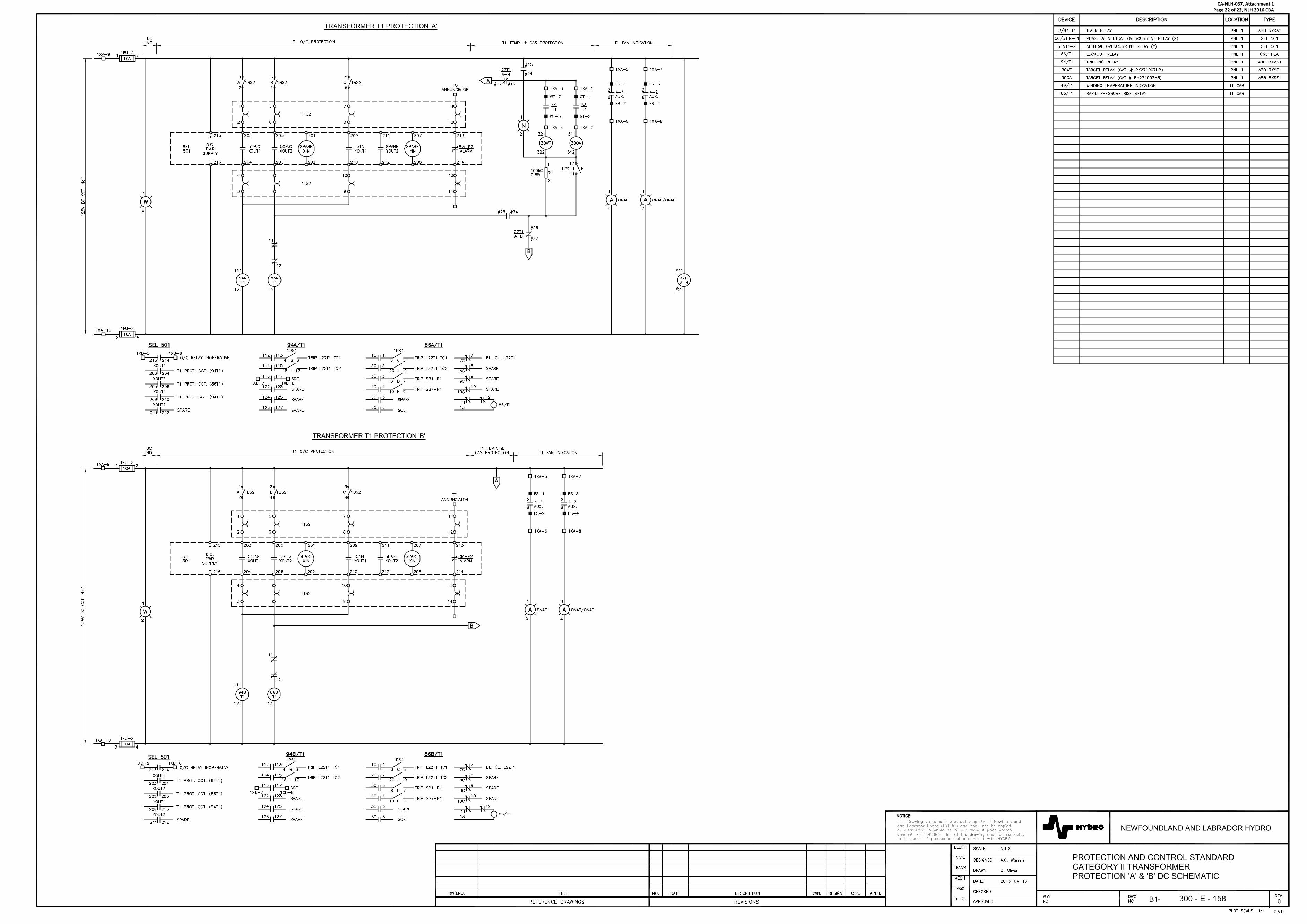
4.2.4 Schematic Development
A typical Single Line Protection Schematic (A and B scheme), as used by NL Hydro for a Category II
transformer, is provided in Appendix C. A typical Protection DC Schematic (A and B scheme), as used by
NL Hydro for a Category II transformer, is provided in Appendix D. These schemes are used on
transformers having an MVA rating below 10 MVA.
4.3 Category III – Small transformers in stations less than 10 MVA
(fused)
Where relay protection is not considered practical, power fuses are applied to protect Category III
transformers.
One protection criterion for selecting a fuse rating is that it should dependably detect all faults on the LV
side of the transformer. “Dependable” protection shall mean that the minimum current through a fuse
during a fault on the other side of the transformer shall be at least twice the total clearing current at 300
seconds. The most critical type of fault is a single line to ground fault on the wye side of a delta wye
connected transformer. For this fault the maximum phase current in two phases of the delta side is only
57% of the ground fault current on the wye side (on a per unit basis). In certain cases, where it is
considered to be not possible to achieve a dependability factor of at least 2, the factor may be reduced
to as low as 1.7.
1 This sensitivity criterion may limit the loadability of the transformer to less than its fully forced
rating in some cases, particularly in the case of delta-wye transformers.
2 Another criterion is that the fuse should operate below the transformer damage curve for fault
conditions.
3 Additionally, the fuse must not be damaged by magnetizing or cold load inrush.
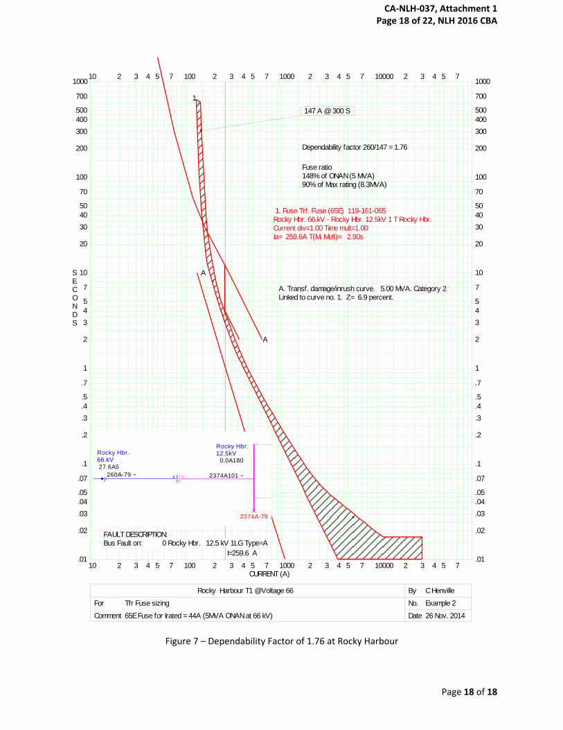
Figure 7 shows an example of a fuse applied at Rocky Harbour. It can be seen that the dependability
factor is less than 2 in this case, but still above 1.7. It can also be seen that the fuse rating will not allow
the transformer to be continuously loaded to its fully forced rating of 8.3 MVA. It can also be seen that
CA-NLH-037, Attachment 1 Page 16 of 22, NLH 2016 CBA

Page 17 of 18
the fuse rating of 148% of the naturally cooled rating of 5 MVA will barely allow a cold load to be picked
up, assuming a cold load pickup factor of 1.5.
If satisfactory dependability and/or loadability cannot be achieved with fuses, relayed protection for the
transformer will be required.
Fuses are not able to protect the transformer from overload conditions. Optionally if the transformer is
provided with overload or high temperature non-electrical protection devices, they may be connected
to trip distribution feeder(s) through the recloser(s).
CA-NLH-037, Attachment 1 Page 17 of 22, NLH 2016 CBA
Page 18 of 18
Figure 7 – Dependability Factor of 1.76 at Rocky Harbour
10 2 3 4 5 7 100 2 3 4 5 7 1000 2 3 4 5 7 10000 2 3 4 5 7
10 2 3 4 5 7 100 2 3 4 5 7 1000 2 3 4 5 7 10000 2 3 4 5 7CURRENT (A)
SECONDS
2
3
4
5
7
10
20
30
40
50
70
100
200
300
400
500
700
1000
2
3
4
5
7
10
20
30
40
50
70
100
200
300
400
500
700
1000
.01
.02
.03
.04
.05
.07
.1
.2
.3
.4
.5
.7
1
.01
.02
.03
.04
.05
.07
.1
.2
.3
.4
.5
.7
1
Rocky Harbour T1 @Voltage 66 By C Henville
For Tfr Fuse sizing No. Example 2
Comment 65E Fuse for Irated = 44A (5MVA ONAN at 66 kV) Date 26 Nov. 2014
147 A @ 300 S
Dependability factor 260/147 = 1.76
Fuse ratio148% of ONAN (5 MVA)90% of Max rating (8.3MVA)
I=259.6 A
1
1. Fuse Trf. Fuse (65E) 119-161-065Rocky Hbr. 66.kV - Rocky Hbr. 12.5kV 1 T Rocky Hbr.Current div=1.00 Time mult=1.00Ia= 259.6A T(M. Melt)= 2.90s
A
A
A. Transf. damage/inrush curve. 5.00 MVA. Category 2Linked to curve no. 1. Z= 6.9 percent.
FAULT DESCRIPTION:Bus Fault on: 0 Rocky Hbr. 12.5 kV 1LG Type=A
Wiltondale66.kV
Rocky Hbr.12.5kV Rocky Hbr.
66.kV
2374A-79
0.0A180 27.6A5
32.9A1
2374A101 260A101 260A-79 260A-79
CA-NLH-037, Attachment 1 Page 18 of 22, NLH 2016 CBA
CA-NLH-037, Attachment 1 Page 19 of 22, NLH 2016 CBA
davolied
Draft
CA-NLH-037, Attachment 1 Page 20 of 22, NLH 2016 CBA
davolied
Draft

CA-NLH-037, Attachment 1 Page 21 of 22, NLH 2016 CBA
CA-NLH-037, Attachment 1 Page 22 of 22, NLH 2016 CBA