ca D1-D102:Layout 1 2/10/11 11:51 AM Page 1 · PDF fileD Microminiature For MIL-DTL-83513...
12
Transcript of ca D1-D102:Layout 1 2/10/11 11:51 AM Page 1 · PDF fileD Microminiature For MIL-DTL-83513...

ca_D1-D102:Layout 1 2/10/11 11:51 AM Page 1

Micro
min
iature
D
MDM connectors are used in applicationsrequiring highly reliable, extremely small, light-weight connectors with higher density contactconfigurations than available in traditional rec-tangular connectors. They are available in 8shell sizes accommodating from 9 to 100 con-tacts, and special arrangements of power andcoaxial contacts.
These connectors are designed to meet therapidly increasing demands for an environmen-tal, high performance, rugged, moisture-sealedmicrominiature connector. This connector
employs size 24 MICROPINTM/MICROSOCKETTM contactson .050 (1.27) centers in a contact density identical tothe standard MICRO-D connector series, but with theseadditional features:
• Aluminum shells to provide greater strength,prevent chipping, cracking or breaking, offerelectromagnetic (EMI) and RFI shielding.
• Silicone elastomer compression interfacial sealto provide a moisture and humidity sealbetween each contact and between contactsand shell.
STANDARD MATERIALS AND FINISHESShell
Insulator
Contacts
Mounting Hardware
Kit, Jackpost (3) items
Washer
Standard Epoxy
- 6061-T6 Aluminum alloy per QQ-A-200/8, yellow chromate/ cadmium, Type II, Class 3 over electroless nickel per SAE AMS-C-26074, Class 4.- Liquid Crystal Polymer per MIL-M-24519, Type GLCP-30F (9-100)- Glass filled diallyl phthalate per MIL-M-14, Type SDGF (7*2 and 24*4)- Polyphenylene sulfide per MIL-M-24519, Type GST-40F (16*5)- Polyester per MIL-M-24519, Type GPT-30F (10*10)- Copper alloy, gold plate
- 300 Series stainless steel, passivate
- 300 Series stainless steel, passivate
- 400 Series stainless stell, passivate
- Hysol EE4215/HD3561, color black or Hysol EE4198/HD3561, color green
Coupling
Polarization
Contact SpacingCentersShell Styles
No. of Contacts
Coaxial Cable
Wire Size
Contact Termination
- Friction/jackscrews
- Keystone-shaped shells
- .050 (1.27)
- Plug and receptacle
- 9 thru 100 signal; 5 signal/2 coaxial; 5 signal/2 power; 11 signal/5 coaxial; 11 signal/5 power; 0 signal/10 coaxial; 0 signal/10 power; 20 signal/4 coaxial; 20 signal/4 power
- RG - 178/U
- #24 thru #32 AWG
- Multiple indent crimp
MECHANICAL FEATURES
The table below summarizes the results of key tests performed in accordance with MIL-STD-1344, whereapplicable. Data is applicable to standard connectors with standard termination. Variations may affect this data, so please consult customer service for further information on your requirements.
TestDielectric Withstanding
VoltageMethod 3001:
Insulation Resistance Method 3003
600 VAC at sea level150 VAC at 70,00' altitude
No breakdownNo breakdown
5,000 megohms minimum
No physical damage
No physical damageNo loss of continuity > 1 µsec
No physical damageNo loss of continuity > 1 µsecNo mechanical or electrical defects
Insulation resistance > 100 megohmsShall be capable of mating and unmating,and meet contact resistance requirements
8 milliohms maximum10 milliohms maximum5 lb. minimum axial load
- 55˚C to +125˚C
50 G's, 3 axes, 6 millisecondduration sawtooth pulse
20 G's, 10-2,000 Hz. 12 hrs
48 hours
At 3 ampsAt 1 milliamp
Thermal Shock Method 1003. Condition A:
Physical Shock Method 2004, Condition E:
Vibration Method 2005, Condition IV:
Durability 500 cycles of mating andunmating, 500 CPH max.
Moisture Resistance Method 1002, Type II, omit steps 7a & 7bSalt Spray Method 1001, Condition B:
Contact Resistance(MIL-STD-202)
Method 1001, Condition B:
Contact Retention Per MIL-DTL-83513
Method Criteria of Acceptance
D-7
Dimensions shown in inches (mm)Specifications and dimensions subject to change
Micro-D Metal Shell - .050" Contact SpacingMDM
Specifications
Performance Data
www.ittcannon.com
ca_D1-D102:Layout 1 2/10/11 11:51 AM Page 7

D
Micro
min
iatu
re
For MIL-DTL-83513 ordering information see pages D-15 and D-16.
SERIES
RoHS COMPLIANCE
MDM 51 P H 001 P XXX- -
SERIES
CONTACT ARRANGEMENTS
CONTACT TYPE
TERMINATION TYPE
CONTACT ARRANGEMENTS
CONTACT TYPE
TERMINATION TYPE
TERMINATION CODE
TERMINATION CODE*
HARDWARE
MDM: (Size 9-100) Liquid Crystal Polymer (LCP)MDM: (Combo Layout) Diallyl Phthalate (DAP)
(H) 001 - 18",7/34 strand,#26 AWG,MIL-W-16878/4, Type E Teflon, yellow.
(H) 003 - 18", 7/34 strand, #26 AWG,MIL-W-16878/4, Type E Teflon,color coded to MIL-STD-681 System I.
M - Military specification hardware, seepage B-11 for military hardware codes.
P - JackpostK - Jackscrew-standard profileL - Jackscrew-low profile
F - Float mountB - No hardware standard
.091 (2.31) dia. hole for sizes 9-51;
.120 (3.05) dia. hole for size 100.A - .125 (3.18) dia. mounting holes for sizes 9-51;
.166 (4.22) dia. hole for size 100.B1 - .1475 (3.75) dia. hole for size 100
(Per MIL-DTL-83513)
No Number - (Standard cadmium/yellowchromate over nickelA174 - Electroless nickelA172 - Gold over nickelA141 - Irridite/alodineA30 - Black anodize
*See page D-9 for a list of standard termination codes.
9-15-21-25-31-37-51-100 (standard)16C5, 10C10, 7C2, 24C4 (coaxial)16P5, 10P10, 7P2, 24P4 (power)
P - Pin S - Socket
H - Harness-insulated wire.L - Solid-uninsulated wire.S - Solder pot to accept #26 AWG MAX.
harness wire. (Not available with powercontact arrangements.)
or combination ofcoax and power
SHELL FINISH MOD CODES
HARDWARE
SHELL FINISH MOD CODES
} (L) 1 - 1/2" uninsulated solid #25AWG gold plated copper.
(L) 2 - 1" uninsulated solid #25 AWGgold plated copper.
R
D-8
Dimensions shown in inches (mm)Specifications and dimensions subject to change
Micro-D Metal Shell - .050" Contact SpacingMDM
How to Order
www.ittcannon.com
ca_D1-D102:Layout 1 2/10/11 11:51 AM Page 8

Micro
min
iature
D
Harness Type (H) n ns a e Type ( )
en3 (76.2)
6 (152.4)
8 (203.2)
10 (254.0)
12 (304.8)
18 (457.2)
20 (508.0)
24 (609.6)
30 (762.0)
36 (914.4)
48 (1219.2)
72 (1828.8)
120 (3048.0)
* Cavity #1 black
H020
H019
H026
H029
H028
H001
H038
H009
H010
H011
H013
H017
H042
H027
H016
H034
H025
H002
H003
H023
H004
H005
H006
H048
H046
H041
L61
L56
L57
L39
L58
L1
L14
L2
L7
L6
L16
L10
.125 (3.18)
.150 (3.81)
.190 (4.83)
.250 (6.35)
.375 (9.52)
.500 (12.70)
.750 (19.05)
1.000 (25.40)
1.500 (38.10)
2.000 (50.80)
2.500 (63.50)
3.000 (76.20)
#26 AWG per MIL-W-16878/4, 7/34 strand, type E Teflon, stranded. #25 AWG gold plated copper
e r e Ter na n e en
The following termination codes are listed for your information. For additional codes please referto Appendix on page D-98 to D-102. All wire lengths are minimum.
Cannon Termination Code (Not MS)
(Face View of Pin insert - Use Reverse Order for Socket Side)
Standard
9 Contacts
1 2 3 4 5 1 2 3 4 5 6 7 8 1 2 3 4 5 6 7 8 9 10 11
1 2 3 4 5 6 7 8 9 10 11 12 13 14 15 16 17 18 191 2 3 4 5 6 7 8 9 10 11 12 13 14 15 161 2 3 4 5 6 7 8 9 10 11 12 13
1 2 3 4 5 6 7 8 9 10 11 12 13 14 15 16 17 18
1 2 3 4 5 6 7 8 9 10 11 12 13 14 15 16 17 18 19 20 21 22 23 24 25 26
27 28 29 30 31 32 33 34 35 36 37 38 39 40 41 42 43 44 45 46 47 48 49 50 51
52 53 54 55 56 57 58 59 60 61 62 63 64 65 66 67 68 69 70 71 72 73 74 7576 77 78 79 80 81 82 83 84 85 86 87 88 89 90 91 92 93 94 95 96 97 98 99 100
A1A1 A2 A3 A41 2 3 4 5 6 7
8 9 10 11 12 13
14 15 16 17 18 19 20
A21 2 3
4 5
36 37 38 39 40 41 42 43 44 45 46 47 48 49 50 51
20 21 22 23 24 25 26 27 28 29 30 31 32 33 34 35 36 3717 18 19 20 21 22 23 24 25 26 27 28 29 30 3114 15 16 17 18 19 20 21 22 23 24 25
19 20 21 22 23 24 25 26 27 28 29 30 31 32 33 34 35
9 10 11 12 13 14 15 12 13 14 15 16 17 18 19 20 216 7 8 9
15 Contacts 21 Contacts
37 Contacts31 Contacts25 Contacts
51 Contacts
Coaxial
Size 51 Shell20 Micro contacts4 Coax or 4 Power
(Not MS)
Size 25 Shell5 Micro contact
2 Coax or 2 Power
.320(8.13)
A2A1 A3 A4 A55 6 7
9 10 118
2 3 41
Size 51 Shell11 Micro contact
5 Coax or 5 Power
.714 (18.14)
.460 (11.68)
.007(0.18)
.043(1.09)
100 Contacts
Contact identification numbers are for reference only and do not appear on insulator or connector body.
.103
.025(0.64)TYP..050
(1.27)TYP.
Size 100 Shell0 Micro contact
10 Coax or 10 Power
A2A1 A3 A4 A5
A7A6 A8 A9 A10
D-9
Dimensions shown in inches (mm)Specifications and dimensions subject to change
Micro-D Metal Shell - .050" Contact SpacingMDM
COTS or Non Mil-Spec or Commercial or Industrial Standard Wire Termination Codes
Contact Arrangements
www.ittcannon.com
ca_D1-D102:Layout 1 2/10/11 11:51 AM Page 9

D
Micro
min
iatu
re
Plug
Receptacle
Receptacle (MDM-100 only)
Solder Pot
Solder Pot
Pigtail termination
.110 (2.79)MAX.
.110 (2.79)MAX.
.200 (5.08)MAX.
.200 (5.08)MAX.
D
D
D
F
F
F
TWO MTG. HOLES.091 ±.003(2.31 ±0.08)
TWO MTG. HOLES.091 ±.003(2.31 ±0.08)
TWO MTG. HOLES.120 ±.003(3.05 ±0.08)
.284 (7.21)MAX.
.296 (7.52)MAX.
.416 (10.57)MAX.
.429 (10.09)MAX.
.429 (10.90)MAX. .198 (5.03)
MAX.
.296 (7.52)MAX.
.394 (10.01)MAX.
C
C
C
B
B
B
.186 (4.72)MAX.
.093(2.36)REF.
.093(2.36)REF.
.093 (2.36)REF.
.198 (5.03)MAX.
A
A
A
E
E
E
G
G
G
Part NumberBy Shell SizeMDM-9P*
MDM-9S*
MDM-15P*
MDM-15S*
MDM-21P*
MDM-21P*
MDM-25P*
MDM-25S*
MDM-31P*
MDM-31S*
MDM-37P*
MDM-37S*
MDM-51P*
MDM-51S*
MDM-100P*
MDM-100S*
.785 (19.94)
.785 (19.94)
.935 (23.75)
.935 (23.75)
1.085 (27.56)
1.085 (27.56)
1.185 (30.10)
1.185 (30.10)
1.335 (33.91)
1.335 (33.91)
1.485 (37.72)
1.485 (37.72)
1.435 (36.45)
1.435 (36.45)
2.170 (55.12)
2.170 (55.12)
.334 (8.48)
.402 (10.21)
.484 (12.29)
.552 (13.97)
.634 (16.10)
.702 (17.83)
.734 (18.64)
.802 (20.37)
.884 (22.45)
.952 (24.18)
1.034 (26.26)
1.102 (27.99)
.984 (24.99)
1.052 (26.72)
1.384 (35.15)
1.508 (38.10)*Add lead type and length; see How To Order. ***Weight given is 1/2", uninsulated, solid, #25 AWG gold plated copper pigtails.
.400 (10.16)
.400 (10.16)
.550 (13.97)
.550 (13.97)
.700 (17.78)
.700 (17.78)
.800 (20.32)
.800 (20.32)
.950 (24.13)
.950 (24.13)
1.100 (27.94)
1.100 (27.94)
1.050 (26.67)
1.050 (26.67)
1.442 (36.63)
1.442 (36.63)
.270 (6.86)
.270 (6.86)
.270 (6.86)
.270 (6.86)
.270 (6.86)
.270 (6.86)
.270 (6.86)
.270 (6.86)
.270 (6.86)
.270 (6.86)
.270 (6.86)
.270 (6.86)
.310 (7.87)
.310 (7.87)
.360 (9.14)
.360 (9.14)
.308 (7.82)
.308 (7.82)
.308 (7.82)
.308 (7.82)
.308 (7.82)
.308 (7.82)
.308 (7.82)
.308 (7.82)
.308 (7.82)
.308 (7.82)
.308 (7.82)
.308 (7.82)
.351 (8.92)
.351 (8.92)
.394 (10.01)
.394 (10.01)
.565 (14.35)
.565 (14.35)
.715 (18.16)
.715 (18.16)
.865 (21.97)
.865 (21.97)
.965 (24.51)
.965 (24.51)
1.115 (28.32)
1.115 (28.32)
1.265 (32.13)
1.265 (32.13)
1.215 (30.86)
1.215 (30.86)
1.800 (45.72)
1.800 (45.72)
.185 (4.70)
.253 (6.43)
.185 (4.70)
.253 (6.43)
.185 (4.70)
.253 (6.43)
.185 (4.70)
.253 (6.43)
.185 (4.70)
.253 (6.43)
.185 (4.70)
.253 (6.43)
.228 (5.79)
.296 (7.52)
.271 (6.88)
.394 (10.01)
.063 (1.79)
.063 (1.79)
.084 (2.39)
.083 (2.37)
.105 (2.99)
.104 (2.97)
.119 (3.39)
.118 (3.36)
.140 (3.99)
.139 (3.96)
.161 (4.59)
.160 (4.56)
.193 (5.50)
.188 (5.35)
.500 (14.3)
1.040 (29.5)
AMax.
BMax.
CMax.
DMax.
EMax.
F+_.005(0.13)
GMax.
Average Weights**oz. (gm.) ±5%
.200 ±.005(5.08 ±0.13)
Plug and ReceptacleRear Mounted
Plug and ReceptacleFront Mounted
Plug Front MountedReceptacle Rear Mounted
.395 ±.005(10.03 ±0.13)
.300 ±.005(7.62 ±0.13)
D-10
Dimensions shown in inches (mm)Specifications and dimensions subject to change
Micro-D Metal Shell - .050" Contact SpacingMDM
COTS or Non Mil-Spec or Commercial or Industrial Shell Dimensions (Conforms to MIL-DTL-83513)
Panel Mounting Dimensions (Sizes 9 - 100)
www.ittcannon.com
ca_D1-D102:Layout 1 2/10/11 11:51 AM Page 10
Micro
min
iature
D
+ + + +
+ + + +
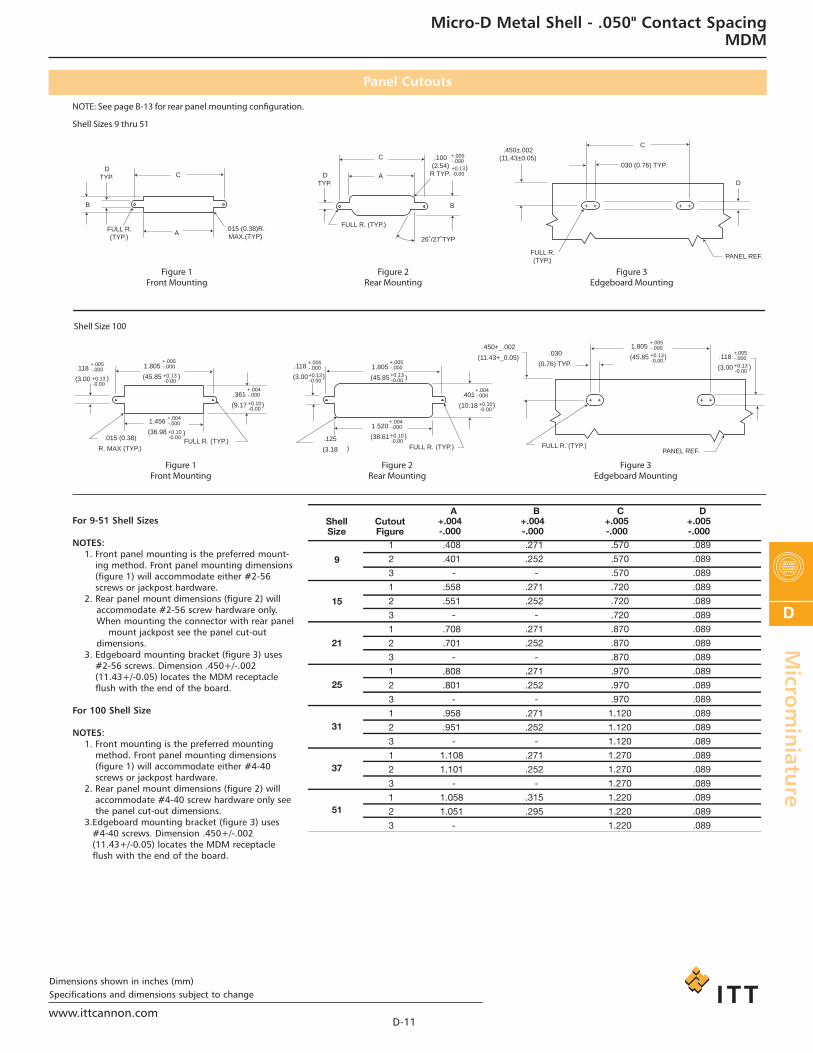
Shell Sizes 9 thru 51
Shell Size 100
Figure 1Front Mounting
DTYP. D
TYP.
B
C
C
A
A
B
.100(2.54)
R TYP.
.450±.002 (11.43±0.05)
FULL R. (TYP.)
C
.030 (0.76) TYP.
D
PANEL REF.
)
.118
(3.00
1.805
(45.85
.015 (0.38)
R. MAX (TYP.) FULL R. (TYP.)
FULL R. (TYP.) FULL R. (TYP.) PANEL REF.
)
.118
(3.00 )
.118
(3.00 )
)
+.005-.000 1.805
(45.85 )
1.805
(45.85 )
.125
(3.18 )
1.456
(36.98 )+0.10-0.00
.361
(9.17 )
1.520
(38.61 )
.401
(10.18
.450+_.002
(11.43+_0.05).030
(0.76) TYP.
)
.015 (0.38)R.MAX.(TYP)
FULL R.(TYP.)
FULL R. (TYP.)
26˚/27˚TYP
Figure 2Rear Mounting
Figure 3Edgeboard Mounting
Figure 1Front Mounting
Figure 2Rear Mounting
Figure 3Edgeboard Mounting
NOTE: See page B-13 for rear panel mounting configuration.
+0.13-0.00
+.005-.000
+0.13-0.00
+.004-.000
+0.10-0.00
+.004-.000
+.005-.000+0.13-0.00
+0.10-0.00
+.004-.000
+0.10-0.00
+.004-.000
+.005-.000+0.13-0.00
+.005-.000 +0.13-0.00
+.005-.000 +0.13-0.00
+.005-.000+0.13-0.00
ShellSize
CutoutFigure
1
2
3
1
2
3
1
2
3
1
2
3
1
2
3
1
2
3
1
2
3
.408
.401
-
.558
.551
-
.708
.701
-
.808
.801
-
.958
.951
-
1.108
1.101
-
1.058
1.051
-
.271
.252
-
.271
.252
-
.271
.252
-
.271
.252
-
.271
.252
-
.271
.252
-
.315
.295
.570
.570
.570
.720
.720
.720
.870
.870
.870
.970
.970
.970
1.120
1.120
1.120
1.270
1.270
1.270
1.220
1.220
1.220
.089
.089
.089
.089
.089
.089
.089
.089
.089
.089
.089
.089
.089
.089
.089
.089
.089
.089
.089
.089
.089
9
15
21
25
31
37
51
A+.004-.000
B+.004-.000
C+.005-.000
D+.005-.000
For 9-51 Shell Sizes
NOTES:1. Front panel mounting is the preferred mount-ing method. Front panel mounting dimensions(figure 1) will accommodate either #2-56screws or jackpost hardware.
2. Rear panel mount dimensions (figure 2) willaccommodate #2-56 screw hardware only.When mounting the connector with rear panel
mount jackpost see the panel cut-outdimensions.
3. Edgeboard mounting bracket (figure 3) uses#2-56 screws. Dimension .450+/-.002(11.43+/-0.05) locates the MDM receptacleflush with the end of the board.
For 100 Shell Size
NOTES:1. Front mounting is the preferred mountingmethod. Front panel mounting dimensions(figure 1) will accommodate either #4-40screws or jackpost hardware.
2. Rear panel mount dimensions (figure 2) willaccommodate #4-40 screw hardware only seethe panel cut-out dimensions.
3.Edgeboard mounting bracket (figure 3) uses#4-40 screws. Dimension .450+/-.002(11.43+/-0.05) locates the MDM receptacleflush with the end of the board.
D-11
Dimensions shown in inches (mm)Specifications and dimensions subject to change
Micro-D Metal Shell - .050" Contact SpacingMDM
Panel Cutouts
www.ittcannon.com
ca_D1-D102:Layout 1 2/10/11 11:51 AM Page 11
D
Micro
min
iatu
re
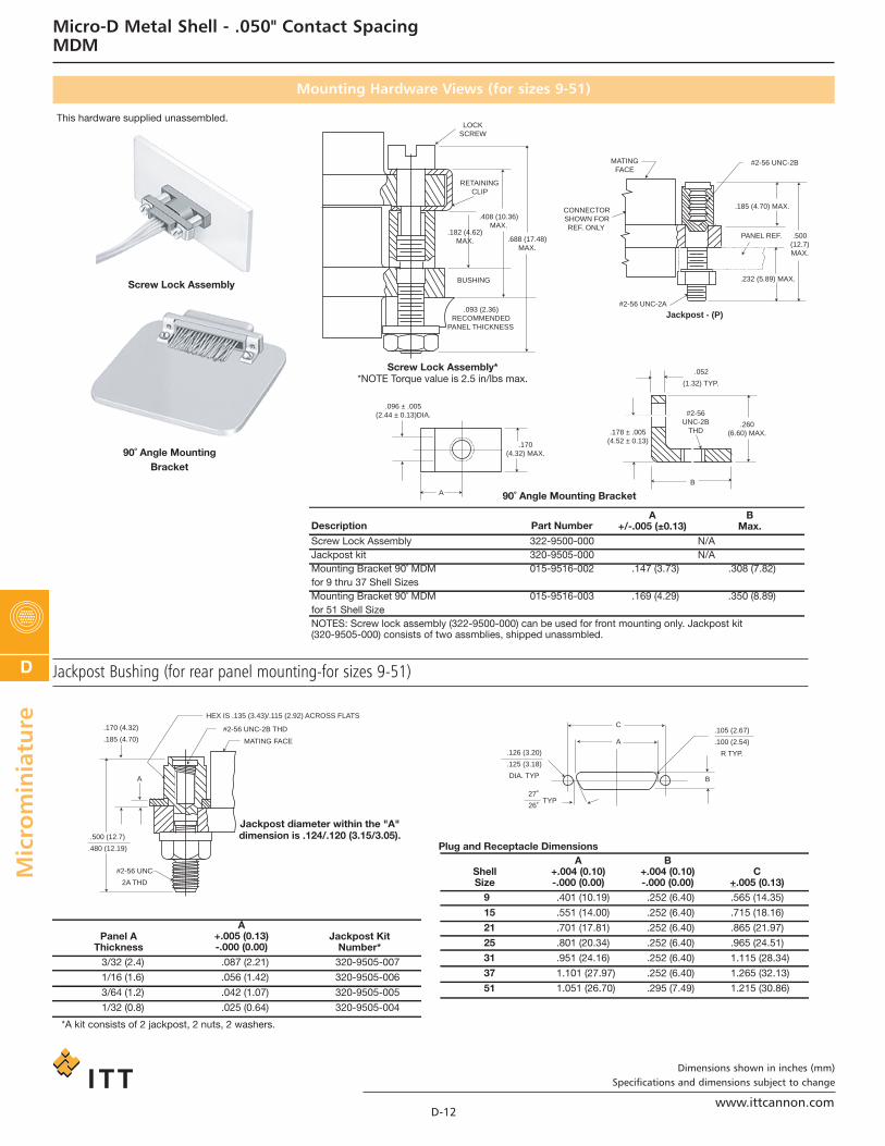
Screw Lock Assembly
90˚ Angle MountingBracket
Screw Lock Assembly**NOTE Torque value is 2.5 in/lbs max.
Jackpost - (P)
90˚ Angle Mounting Bracket
This hardware supplied unassembled.
.052
(1.32) TYP.
.260 (6.60) MAX.
#2-56 UNC-2B
THD
B
.178 ± .005(4.52 ± 0.13)
.096 ± .005(2.44 ± 0.13)DIA.
.093 (2.36)RECOMMENDED
PANEL THICKNESS
BUSHING
.182 (4.62) MAX. .688 (17.48)
MAX.
.408 (10.36) MAX.
RETAINING CLIP
LOCK SCREW
MATING FACE
CONNECTOR SHOWN FOR REF. ONLY
#2-56 UNC-2B
.185 (4.70) MAX.
.500 (12.7) MAX.
PANEL REF.
.232 (5.89) MAX.
#2-56 UNC-2A
.170(4.32) MAX.
A
Description
Screw Lock Assembly Jackpost kitMounting Bracket 90˚ MDMfor 9 thru 37 Shell Sizes Mounting Bracket 90˚ MDMfor 51 Shell Size NOTES: Screw lock assembly (322-9500-000) can be used for front mounting only. Jackpost kit (320-9505-000) consists of two assmblies, shipped unassmbled.
322-9500-000320-9505-000015-9516-002
015-9516-003
.147 (3.73) .169 (4.29)
.308 (7.82) .350 (8.89)
N/A N/A
Part NumberA
+/-.005 (±0.13)B
Max.
Jackpost Bushing (for rear panel mounting-for sizes 9-51)
3/32 (2.4)
1/16 (1.6)
3/64 (1.2)
1/32 (0.8)
*A kit consists of 2 jackpost, 2 nuts, 2 washers.
.087 (2.21)
.056 (1.42)
.042 (1.07)
.025 (0.64)
320-9505-007
320-9505-006
320-9505-005
320-9505-004
Panel AThickness
Jackpost KitNumber*
9
15
21
25
31
37
51
.401 (10.19)
.551 (14.00)
.701 (17.81)
.801 (20.34)
.951 (24.16)
1.101 (27.97)
1.051 (26.70)
.252 (6.40)
.252 (6.40)
.252 (6.40)
.252 (6.40)
.252 (6.40)
.252 (6.40)
.295 (7.49)
.565 (14.35)
.715 (18.16)
.865 (21.97)
.965 (24.51)
1.115 (28.34)
1.265 (32.13)
1.215 (30.86)
ShellSize
Plug and Receptacle Dimensions
Jackpost diameter within the "A"dimension is .124/.120 (3.15/3.05).
HEX IS .135 (3.43)/.115 (2.92) ACROSS FLATS
#2-56 UNC-2B THD
MATING FACE
.170 (4.32)
.185 (4.70)
A
.500 (12.7)
.480 (12.19)
#2-56 UNC
2A THD
.126 (3.20)
.125 (3.18)
DIA. TYP
.105 (2.67)
.100 (2.54)
R TYP.
27˚
26˚TYP
A
C
B
A+.004 (0.10)-.000 (0.00)
B+.004 (0.10)-.000 (0.00)
C+_.005 (0.13)
A+.005 (0.13)-.000 (0.00)
D-12
Dimensions shown in inches (mm)Specifications and dimensions subject to change
Micro-D Metal Shell - .050" Contact SpacingMDM
Mounting Hardware Views (for sizes 9-51)
www.ittcannon.com
ca_D1-D102:Layout 1 2/10/11 11:51 AM Page 12

Micro
min
iature
D
This hardware is factory installed.
.014 ± .004
(0.36 ± 0.10) ALLOWABLEDIAMETRAL FLOAT
.020 (0.51) MAX. ALLOWABLEAXIAL FLOAT
.150 ± .003
(3.81 ± .076)
.185 (4.70)MAX .093
(2.36)REF.
.090 ± .0015
(2.29 ± 0.038)DIA .031 ± .003
(0.79 ± 0.08)
MATING FACE
MATINGFACE
#2-56UNC-2A
.490(12.45) MAX
.735 (18.67) MAX.
MATINGFACE
CONNECTORSHOWN FORREF ONLY
HEX HEAD -.050 (1.27) ACROSS FLATS .050 (1.27) DEEP (REF)
.155 (3.94) MAX.
PART HAS A .040 (1.02)MAX. AXIAL FLOAT#2-56 UNC-2A
Jackscrew - (L) Low ProfileJackscrew - (K) Standard ProfileFloat Mount - (F)
Shown here is a cutaway view of the float mount for the MDM connector. The basic shell dimensions are the same for the float mount and the screw mounting hole configurations. View shown is for standard float mount front panel mounting. Reverse mounting is available on request.
* NOTE: Torque values are as follows: Low Profile Jackscrew (L)-2.5 in-lbs Standard Jackscrew (K)-2.5 in-lbs
PART HAS A .040 (1.02) MAX AXIAL FLOAT
CONNECTOR SHOWN FORREF. ONLY
This hardware supplied in kits unassembled (2 pieces of each item).
#2-56 UNC-2ATHREAD TYP.
PLUG (REF. WITH.092 (2.34) DIA.MOUNTING HOLES
POTTING WELL (REF.)
.361 (9.17) MAX.
.390 (9.91) MAX.SIZE 100 ONLY
.010 (0.25)TH'K (REF.)
.062 (1.57)HEX. (REF.)
.868 (22.05) MAX.
.902 (22.91) MAX.
.010 (0.25)TH'K (REF.)
#2-56 UNC-2ATHREAD TYP.
PLUG (REF.) WITH.092 (2.34) DIA.MOUNTING HOLES
POTTING WELL(REF.)
Figure 1. Jackscrew - Low profileSlotted Head
Size 9-51Size 100*
Allen headOptional Head Configuration
Plug and ReceptacleLow and High Profile
Size 9-51Size 100* (same dimensions)
Figure 2. Jackscrew - High ProfileSlotted Head
Size 9-51Size 100*
To order hardware kits separately, order either by M83513/5-** or by 320-950X-XXX.
DescriptionSlotted Head Jackscrew Assy Low Profile (Figure 1) M5 320-9508-025
M6 320-9508-027
M2 320-9508-026
M3 320-9508-028
M7 320-9505-033
05
06
02
03
07
M15 320-9508-021
M16 320-9508-023
M12 320-9508-022
M13 320-9508-024
M17 320-9505-030
*Size 100 requires B1 size mounting holes for Mil-Spec hardware
Note: Torque values as follows:
Size 9-51 4.0 in-lbs
Size 100 6.0 in-lbs
15
16
12
13
17
Slotted Head Jackscrew Assy High Profile (Figure 2)
Allen Head Jackscrew Assy Low Profile (Figure 1)
Allen Head Jackscrew Assy High Profile (Figure 2)
Jackpost Assy (Figure 3)
Size 9-51Mod Code Part Number
Size 100*Mod Code Part Number* * * *
.125 (3.18) HEX.
.187 (4.75) HEX.#2-56 UNC-2B THREAD#4-40 UNC -2A THREAD
LOCKWASHER
RETAINING NUT.154 (3.91) HEX..187 (4.75) HEX.
.062 ± .010(.157 ± 0.25)
SIZE 100 SAME
.475 ± .025(12.06 ± 0.64)
SIZE 100 SAME
.190/.185(4.83/4.70)
.185/.175(4.70/4.44)
Figure 3. Jackpost AssemblySize 9-51Size 100*
D-13
Dimensions shown in inches (mm)Specifications and dimensions subject to change
Micro-D Metal Shell - .050" Contact SpacingMDM
Mounting Hardware Views (sizes 9-51)
Mounting Hardware to Military Specification (for sizes 9 - 100) per MIL-DTL-83513/5
www.ittcannon.com
ca_D1-D102:Layout 1 2/10/11 11:51 AM Page 13

D
Micro
min
iatu
re
This hardware supplied unassembled.
#4-40 UNC-2A THD
#4-40 UNC-2B NOTHING OR FEMALE THD
.185 (4.70)MAX.
.500 (12.70)MAX.
PANEL -MAY BE USED WITH.093 (2.36) MAXTHICK PANEL
.123 ± .005(3.12 ± 0.13) DIA.
#4-40 UNC-2BTHD
A
.395 (10.03)MAX.
.235 ± .005(5.97 ± 0.13)
.064 ± .010(1.62 ± 0.25) TYP.
B
180(4.57 )
+.010-.005+.025-0.13
Jackpost - (P)90˚Angle MountingBracket
90° Angle MountingBracket
Description
Jackpost kit
Mounting Bracket 90˚ MDM
320-9505-015
015-9528-000 .191 (4.85) .370 (9.40)
N/A
Part NumberA
± .005 (0.13)B
Max.
#4 LOCK WASHER
MATING SIDE
Note: Size 100 requires .120 dia (B) mounting hole
when using Commercial (P) jackpost kits.
MATINGFACE
#4-40UNC-2ATHD
.735 (18.67)MAX.
Jackscrew - (K) Standard
PART HAS A .040 (1.02)MAX AXIAL FLOAT
CONNECTORSHOWN FORREF. ONLY
This hardware is factory installed.
.014 ± .004(0.36 ± 0.10) ALLOWABLE
DIAMETRAL FLOAT.020 (0.51) MAX. ALLOWABLE
AXIAL FLOAT
.174 ± .005
(4.4 ± .10)
.185 (4.70)MAX .093
(2.36)REF.
.116 ± .002(2.29 ± .051)
DIA.031 ± .003
(0.79 ± 0.08)
MATINGFACE
Float Mount - (F) Std.
HEX. SOCKET HEAD..078 (1.98) ACROSS FLATS
.050 (1.27) MIN. DEPTH
.155 (3.94) MAX.
.040 (1.02) MAX.AXIAL FLOAT
#4-40 UNC-2A THDMATING SIDE
*NOTE: Torque values are as follows:Low Profile Jackscrew (L)-4.0 in-lbs
Standard Profile Jackscrew (K)-4.0 in-lbs
Jackscrew - (L) (Low Profile)
ENGAGING FACE
RECEPTACLE SHOWNFOR REF. ONLY
#4-40 THREADRETAINING NUT
.500 (12.70)MAX.
.185 (4.70)
.170 (4.32)A
#4-40 UNC-2B
3/16" HEX.LOCKING POST
.125
(3.18
1.516
(38.51
.401
(10.18
1.800 ± .005(45.72 ± 0.13)
.161 (4.09)
.159 (4.04)DIA.
R
)
+.004-.000+1.10-0.00
)
+.004-.000+1.10-0.00
)
+.005-.000+0.13-0.00
PanelThickness
Jackpost KitNumber*
Dimensions for Rear Panel Mounting
A+.005 (0.13)-.000 (0.00)
3/32 (2.4)
1/16 (1.6)
1/32 (0.8)
3/64 (1.2)
*2 jackposts, 2 nuts, 2 washers
.087 (2.21)
.058 (1.42)
.025 (0.64)
.042 (1.07)
320-9505-013
320-9505-012
320-9505-010
320-9505-011
Torque value for size 100
Note: Size 100 requires B mounting hole shell
size when using rear panel mount jackposts
D-14
Dimensions shown in inches (mm)Specifications and dimensions subject to change
Micro-D Metal Shell - .050" Contact SpacingMDM
Mounting Hardware Views (for size 100)
Jackpost Bushing (for Rear Panel Mounting)
www.ittcannon.com
ca_D1-D102:Layout 1 2/10/11 11:51 AM Page 14

Micro
min
iature
D
.040 (1.02) MAX. ALLOWABLEAXIAL FLOAT JACKSCREW/JACKPOST BUSHING
(FOR REFERENCE ONLY SEEORDERING INFORMATION BELOW.)
MICROSOCKET
CONNECTOR RECEPT
INTERFACIAL SEAL
.185 (4.70) MAX. (TYP.)
E-RING (TYP.)
CONNECTOR, PLUG
BACKPOTTING, EPOXY
.790 (20.07) MAX.
.315(8.00)MAX.
.090 (2.29) REF.(TYP.)
.900 (22.86) REF.
MDM Size 9 Shown
#2-56 UNC-2A THD (9-51)(TYP.)
MICROPIN
C
B A
Save wear and tear on your equipment andsystems connectors by using the "ConnectorSaver".
The multi-matings and unmatings experi-enced by most connectors during testing andfinal check out can be eliminated.
Simply mate the "Connectors Saver" to yourunit and use the opposite side for your test-ing interface...less wear, less tear, less chanceof damage. It is available in all eight standardMDM layouts. Mating hardware is availableand can be ordered either separately orincluded with the connector saver.
Size
9
15
21
25
31
37
51
100
MDM98479-86
MDM98479-87
MDM98479-88
MDM98479-89
MDM98479-90
MDM98479-91
MDM98479-92
MDM98479-93
MDM98479-18
MDM98479-19
MDM98479-20
MDM98479-21
MDM98479-14
MDM98479-15
MDM98479-16
MDM98479-17
MDM98479-78
MDM98479-79
MDM98479-80
MDM98479-81
MDM98479-82
MDM98479-83
MDM98479-84
MDM98479-85
MDM-97294-371
MDM-97294-372
MDM-97294-373
MDM-97294-374
MDM-97294-375
MDM-97294-376
MDM-97294-377
MDM-97294-717
320-9505-014**
320-9505-014**
320-9505-014**
320-9505-014**
320-9505-014**
320-9505-014**
320-9505-014**
320-9508-014***
.785 (19.94)
.935 (23.75)
1.085 (27.56)
1.185 (30.10)
1.335 (33.91)
1.485 (37.72)
1.435 (36.45)
2.170 (55.12)
Kit contains 2 jackpost/jackscrew bushings and 2 E-Rings.Size 9-51-#2-56 UNC-2B ThreadSize 100-#4-40 UNC-2B Thread
***
***
.565 (14.35)
.715 (18.16)
.865 (21.97)
.965 (24.51)
1.115 (28.32)
1.265 (32.13)
1.215 (30.86)
1.800 (45.72)
.308 (7.82)
.308 (7.82)
.308 (7.82)
.308 (7.82)
.308 (7.82)
.308 (7.82)
.351 (8.91)
.394 (10.01)
With HardwareElectroless Nickel (A174) Plated Cadmium over Nickel (A101) Plated
W/O Hardware With Hardware W/O Hardware *Hardware KitsA
Max.B
± .005 (0.13)C
Max.
D-15
Dimensions shown in inches (mm)Specifications and dimensions subject to change
Micro-D Metal Shell - .050" Contact SpacingMDM
Connector Saver
www.ittcannon.com
ca_D1-D102:Layout 1 2/10/11 11:51 AM Page 15
D
Micro
min
iatu
re
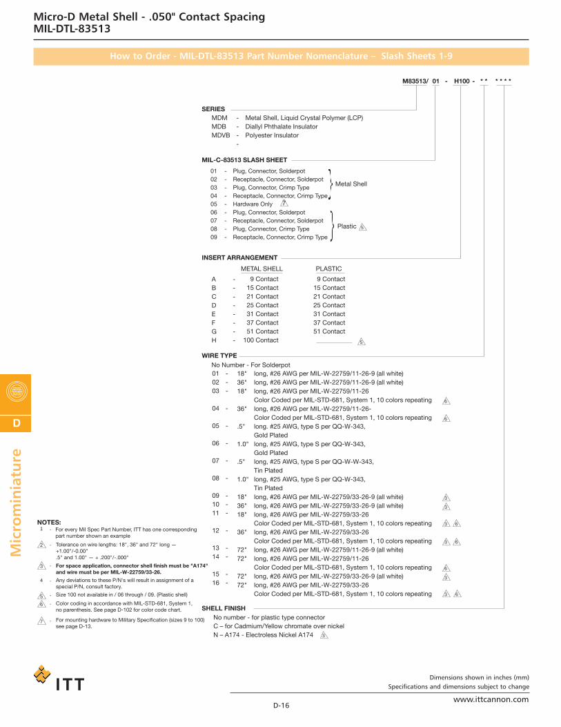
SERIESMetal Shell, Liquid Crystal Polymer (LCP)Diallyl Phthalate InsulatorPolyester Insulator
MDMMDBMDVB
----
Plug, Connector, SolderpotReceptacle, Connector, SolderpotPlug, Connector, Crimp TypeReceptacle, Connector, Crimp TypeHardware OnlyPlug, Connector, SolderpotReceptacle, Connector, SolderpotPlug, Connector, Crimp TypeReceptacle, Connector, Crimp Type
Metal Shell
Plastic
010203040506070809
---------
long, #26 AWG per MIL-W-22759/11-26-9 (all white)long, #26 AWG per MIL-W-22759/11-26-9 (all white)long, #26 AWG per MIL-W-22759/11-26Color Coded per MIL-STD-681, System 1, 10 colors repeatinglong, #26 AWG per MIL-W-22759/11-26-Color Coded per MIL-STD-681, System 1, 10 colors repeatinglong. #25 AWG, type S per QQ-W-343,Gold Platedlong, #25 AWG, type S per QQ-W-343,Gold Platedlong, #25 AWG, type S per QQ-W-W-343,Tin Platedlong, #25 AWG, type S per QQ-W-343,Tin Platedlong, #26 AWG per MIL-W-22759/33-26-9 (all white)long, #26 AWG per MIL-W-22759/33-26-9 (all white)long, #26 AWG per MIL-W-22759/33-26Color Coded per MIL-STD-681, System 1, 10 colors repeatinglong, #26 AWG per MIL-W-22759/33-26Color Coded per MIL-STD-681, System 1, 10 colors repeatinglong, #26 AWG per MIL-W-22759/11-26-9 (all white)long, #26 AWG per MIL-W-22759/11-26Color Coded per MIL-STD-681, System 1, 10 colors repeatinglong, #26 AWG per MIL-W-22759/33-26-9 (all white)long, #26 AWG per MIL-W-22759/33-26Color Coded per MIL-STD-681, System 1, 10 colors repeating
18"36"18"
36"
.5"
1.0"
.5"
1.0"
18"36"18"
36"
72"72"
72"72"
010203
04
05
06
07
08
091011
12
1314
1516
---
-
-
-
-
-
---
-
--
--
9 Contact15 Contact21 Contact25 Contact31 Contact37 Contact51 Contact
100 Contact
METAL SHELL
No Number - For Solderpot
For every Mil Spec Part Number, ITT has one correspondingpart number shown an example
-
-
-
-
-
-
For space application, connector shell finish must be "A174"and wire must be per MIL-W-22759/33-26.
Any deviations to these P/N's will result in assignment of aspecial P/N, consult factory.
Size 100 not available in / 06 through / 09. (Plastic shell)
Color coding in accordance with MIL-STD-681, System 1,no parenthesis. See page D-102 for color code chart.
For mounting hardware to Military Specification (sizes 9 to 100)see page D-13.
No number - for plastic type connectorC – for Cadmium/Yellow chromate over nickelN – A174 - Electroless Nickel A174
Tolerance on wire lengths: 18", 36" and 72" long —+1.00"/-0.00".5" and 1.00" — + .200"/-.000"
PLASTIC
9 Contact15 Contact21 Contact25 Contact31 Contact37 Contact51 Contact
ABCDEFGH
--------
M83513/ 01 * * * * * *H100- -
MIL-C-83513 SLASH SHEET
INSERT ARRANGEMENT
WIRE TYPE
SHELL FINISH
NOTES:
7
5
5
6
6
3
3
3 6
3
7
6
5
4
-1
3
23 6
6
3
3 6
D-16
Dimensions shown in inches (mm)Specifications and dimensions subject to change
Micro-D Metal Shell - .050" Contact SpacingMIL-DTL-83513
How to Order - MIL-DTL-83513 Part Number Nomenclature – Slash Sheets 1-9
www.ittcannon.com
ca_D1-D102:Layout 1 2/10/11 11:51 AM Page 16

Micro
min
iature
D
SERIESConnector, Electrical, RectangularMicrominiature, Polarized ShellPC Board Mounting
long, #24 AWG solid copper wire per QQ-W-343, Type “S”, solder dippedlong, #24 AWG solid copper wire per QQ-W-343, Type “S”, solder dippedlong, #24 AWG solid copper wire per QQ-W-343, Type “S”, solder dipped
.109"
.140"
.172"
010203
---
9 Contact15 Contact21 Contact25 Contact31 Contact37 Contact51 Contact
100 Contact
METAL SHELL
No Number - For Solderpot
-
-
-
For space application, connector shell finish must be "N".
Any deviations to these P/N's will result in assignment of a special P/N, consult customer service.
No letter - for plastic type connectorC - Cadmium / Yellow chromate over nickelN - Electroless Nickel
Tolerance on wire lengths ±.015
ABCDEFGH
--------
M83513/ 10 * * CA-
MIL-C-83513 SLASH SHEET
INSERT ARRANGEMENT
WIRE TYPE
SHELL FINISH
NOTES:
2
3
N - No jackpostP - Jackpost (permanently attached)T - Threaded insert
*
HARDWARE
3
4
-1
3
2
For every Mil Spec Part Number, ITT has one corresponding part number
10 – Connector, Plug, Condensed Board Right Angle (CBR), Sizes 9 – 3711 – Connector, Plug, CBR, Size 5112 – Connector, Plug, CBR, Size 10013 – Connector, Receptacle, CBR, Sizes 9 – 3714 – Connector, Receptacle, CBR Size 5115 – Connector, Receptacle, CBR, Size 10016 – Connector, Plug, Board Right Angle (BR), Sizes 9 – 3717 – Connector, Plug, BR, Size 5118 – Connector, Plug, BR, Size 10019 – Connector, Receptacle, BR, Sizes 9 – 3720 – Connector, Receptacle, BR Size 5121 – Connector, Receptacle, BR Size 10022 – Connector, Plug, Board Straight (BS), Sizes 9 – 3723 – Connector, Plug, BS, Size 5124 – Connector, Plug, BS, Size 10025 – Connector, Receptacle, BS, Sizes 9 – 3726 – Connector, Receptacle, BS, Size 5127 – Connector, Receptacle, BS Size 100
D-17
Dimensions shown in inches (mm)Specifications and dimensions subject to change
Micro-D Metal Shell - .050" Contact SpacingMIL-DTL-83513
How to Order - MIL-DTL-83513 Part Number Nomenclature – Slash Sheets 10-27
www.ittcannon.com
ca_D1-D102:Layout 1 2/10/11 11:51 AM Page 17