CA Breaker Instruction Manual - homewoodsales.com … · CA Breaker Instruction Manual 1Volume ....
46
HOMEWOOD PRODUCTS CORPORATION Westinghouse Technology CA Breaker Instruction Manual Volume 1
Transcript of CA Breaker Instruction Manual - homewoodsales.com … · CA Breaker Instruction Manual 1Volume ....

HOMEWOOD PRODUCTS CORPORATION Westinghouse Technology
CA Breaker Instruction Manual
Volume
1
H O M E W O O D P R O D U C T S C O R P O R A T I O N
Compressed Air Circuit Breaker
Homewood Products Corporation 820 Washington Blvd. Pittsburgh, PA 15206
800-777-1172 / 412-665-2700

Table of ContentsIntroduction i
C H A P T E R 1
General Information 1
High Voltage Compartment 3
Current Carrying Path 3
Mechanism Compartment 4
Mechanical Operation 4
Opening or Tripping Operation 5
Closing Operation 5
Arc Chute and Arc Interruption 7
Auxiliary Devices 8
Compressed Air Supply 10
C H A P T E R 2
Receiving 11
Handling 11
Storing 11
C H A P T E R 3
Assembly 13
Air Connections 13
Wiring 14
Trial Operation 17
Air Supply Unit 18
C H A P T E R 4
General 19
Devices Operated by Compressed Air 19
Reservoir, Air Lines, Safety Valve
and Pressure Gauge 19
Pneumatic Mechanism and
Magnet Valves 21
Blast Valve 24
Pressure Switches 28
Control Scheme and Control Panel 31
Shock Absorbers 34
Hand Operating Lever 35
Mechanism Interlock 35
Pole Unit Assembly 36
Arc Chute and Arc Chute Removal 36
Stationary Contact (upper terminal
and contact fingers) 37
Moving Contact 38
Operating Rod, Blast Tube and
Supports 38
Door Interlocks 39
Inspection Check List 39

Introduction The majority of the operation and maintenance information provided in this book comes from the Westinghouse instruction booklet I.B. 33-680-C2A.
Only qualified electrical workers who, by reason of training and experience with high voltage circuits and equipment, are familiar with the work to be performed and the hazards involved should work on this equipment.
CAUTION: The maintenance closing lever should not be used to operate the breaker until all the air has been exhausted from the reservoir, the control switch on the control panel is open, and the isolating switches have been opened.
CAUTION: The breaker must never be tripped manually if the air pressure in the reservoir is below 112 p.s.i.
All possible contingencies, which may arise during installation, operation, or maintenance, and all details and variations of this equipment, do not purport to be covered by these instructions. If the purchaser regarding a particular installation, operation, or maintenance of the equipment desires further information, Homewood Products should be contacted.

11
Description General outline of the Type 150 CA 2500 Breaker
General Information
A Circuit breaker is a device capable of repeatedly interrupting the flow of current in an electrical circuit. Type CA compressed air circuit breakers are devices designed to operate in air with continuous current carrying capacities up to 5000 amperes at 15,500 volts a-c and capable of interrupting fault currents up to 93,000 amperes at 15,500 volts a-c. The indoor breakers are normally used for powerhouse and substation service.
Utilizing compressed air at a pressure of 150 pounds per square inch as a means for mechanically opening and closing breaker contacts as well as for extinguishing a power arc, the Type CA circuit breaker is essentially electro pneumatic in operation. The breaker operating mechanism and control equipment is located near the floor in the mechanism compartment while the contact structure and arc chute, which is at a potential of 13,800 volts, is located in the high voltage compartment as shown in Figure 3.
Chapter
1

22
Figure 3 Breaker side view showing current path

33
High Voltage Compartment Moving Contacts, upper and lower terminals and arc chutes comprise the chief components in the high voltage compartment. This compartment is isolated from the mechanism compartment underneath by a three-eighths thick grounded steel plate and, in addition, there is ample room above the high voltage compartment for the expansion of gases discharged from the arc chute during interruption. A steel plate acts as a barrier between the high voltage compartment and the space above the arc chute in order to prevent the possibility of any gases from the top of the arc chute returning to the contact structured below. Metal barriers are also placed between phases to isolate each pole unit.
Current Carrying Path The actual current path through the breaker is indicated in Figure 3 by means of arrows. This figure shows only one pole of a three pole breaker in order to clarify the illustration. The current is assumed to be entering the upper terminal and then flows into the contact fingers, which are designed to give good contact pressure as well as long wear. From this point, the current passes to the moving contact arm. A break is indicated between the contact fingers and the moving contact arm to show the point of actual parting of moving and stationary contacts although no such gap will exist when the breaker is closed and carrying normal load current. The current then passes from the moving contact arm to contact bridges, which are mechanically held in place in such a manner as to allow the moving contact to rotate freely about the hinge pin, and still provide an excellent current path from the contact bridges to the lower breaker terminal. Figure 5 is a typical 2000-ampere pole unit assembly.
Figure 6 is a typical 4000 and 5000 ampere pole unit. The current carrying parts consist of three moving blade members for engagement with three stationary contact finger blocks. The center contact is provided with “lead” over the two outer contacts. As the breaker opens, the outer contacts separate and transfer their current to the middle contact, which is subjected to compressed air for current interruption. Auxiliary air ducts drilled into the contact base provide auxiliary air blasts to aid in current transfer to the middle contact.
Figure 6: 5000 amp pole units with arc chutes removed.

44
During arc interruption, the current follows exactly the same path as just described except that due to the magnetic effect of the looped current path through the breaker plus the action of the compressed air blast, the arc moves upward from the contact fingers to the arc tip directly above them. The contact tip is electrically a part of the upper terminal casting.
This tip is highly arc resistant and withstands the burning action of the arc thus eliminating burning on the contact fingers which then remain in good condition to carry normal load current. On the moving contact, the same action takes place and a similar piece of arc resistant metal is used on the tip of the moving arm at the point where contacts part. The arc then moves upward into the arc chute where it is extinguished.
Mechanism Compartment The air reservoir, blast valves, pneumatic mechanism and all parts operating at or near ground potential are located in this compartment. Figure 9 shows this compartment and the arrangement of enclosed parts. The electro-pneumatic valves control the flow of compressed air into the pneumatic mechanism, which in turn actuates the breaker moving contact arms. The control voltage is kept separate and isolated from the 13,800 volt a-c circuit in the high voltage compartment.
Figure 9 Mechanism compartment
Mechanical Operation As shown in Figure 4, a single pneumatic mechanism operating through a single shaft synchronizes the operation of the blast valves and three contacts so that blast air is always available for arc extinction when contacts part. Arrows indicate flow of the compressed air out of the reservoir. Mechanical operation of the breaker by hand through use of a hand-operating lever is also possible. However, hand operation of the breaker must never be attempted if the control circuit is energized, or if the breaker terminals are energized. Also, the reservoir should be emptied of compressed air before attempting to use the hand-operating lever.

55
CAUTIONCAUTION Never attempt to operate the breaker with the maintenance handle unless the following three steps are first taken 1. De-energize the breaker – open breaker and isolating switches following the correct procedure. 2. De-energize the control circuit – open the control power switch. 3. Remove air from the reservoir – close the supply valve and open the drain
valve. Opening or Tripping Operation A pneumatic mechanism, consisting of a brass cylinder enclosed on each end, with a piston inside the cylinder, is mounted in the mechanism compartment as shown in Figure 4. When compressed air flowing from the reservoir through piping to the pneumatic mechanism is admitted on the upper side of the mechanism piston, the piston moves downward causing the shaft cam to rotate and the operating rod to pull open the moving contact arm. Arrows indicate the flow of compressed air from the reservoir to the mechanism for a breaker opening operation.
Rotation of the shaft cam causes various levers to open the blast valve thus allowing compressed air to pass from the reservoir up the blast tube and between the separating contacts. The compressed air, after aiding in extinguishing the arc, passes up through the arc chute coolers and out the top of the arc chute. Arrows in Figure 4 indicate flow of the compressed air from the reservoir up the blast tube into the arc chute. The moving contact arm continues to move away from the contact fingers until it reaches its full open position as shown in Figure 5. The shaft cam allows the blast valve levers to drop off the cam and the blast valve closes after circuit interruption.
Closing Operation The closing operation is just the reverse of the opening operation. First, the compressed air, in flowing from the reservoir to the pneumatic mechanism, flows in the bottom of the mechanism and underneath the piston thereby causing the piston to move upward instead of downwards as in the opening or tripping operation. This flow of compressed air is controlled by the opening and closing of the magnet valves on the pneumatic mechanism as shown in Figure 4. During a breaker closing operation, the magnet valve on the bottom of the pneumatic mechanism is open thereby allowing compressed air to flow in underneath the mechanism piston while the magnet valve on the top of the mechanism is closed. The piston, in moving upwards, causes the operating rod to push the moving contact arm up. The moving contact engages the contact fingers thus completing the current path from the lower breaker terminal to the upper breaker terminal. Second, in closing the breaker, the shaft cam rotates clockwise but the blast valve levers are so designed that the blast valve does not open. Due to the speed of the moving contact arm, air blast on closing is not required.

66
Figure 4 Breaker side view showing compressed air flow

77
Arc Chute and Arc Interruption During a breaker opening operation, an arc is drawn between the arc tip on the moving contact arm and the arc tip above the contact fingers. At the same time a blast of compressed air from the reservoir passing up the blast tube causes the arc to be forced up into the arc chute. Figure 4 indicates the location of the arc between the moving contact arm and contact fingers. The arrows show the path of the compressed air blast. Details of the arc chute are shown in Figure 7.
Figure 7: Interruption action of cross blast air breaker.

88
The arc chute consists of fiber plates and cooler assemblies. The hot arc is blown upwards against the fiber splitters by the compressed air blast. The diffusion of the hot arc gases with the fiber gases thus generated and the turbulence created by the compressed air act to de-ionize the hot gases. At the following zero in the current wave, de-ionization has progressed to the point where the air between the contacts from a conductor to an insulator. Further motion of the moving contact inserts an air gap capable of withstanding circuit voltage, Hot arc gases blown through the arc chute during the interrupting process are de-ionized by the cooler assemblies.
Figure 20 shows a view of the arc chute with the side plate removed and shows the relationship of moving contacts with the arc chute.
Figure 20: Side View of Pole Unit Assembly with Arc Chute Side Plate Removed
Auxiliary Devices Certain auxiliary devices are used in order to make breaker operation as completely automatic and as safe as possible. These devices, which are included in a standard breaker, are listed and described briefly as follows:
Control Panel – The control panel makes opening and closing operations of the breaker entirely automatic once the operator has moved the control switch

99
to either close or trip the breaker. The control relays automatically govern the flow of compressed air operating the pneumatic mechanism and de-energize all magnet valve coils and relays after a closing or opening operation has been completed.
Pressure Switches and Safety Valves – Pressure switches are adjusted and connected into the electrical control scheme so as to allow operation of the breaker only so long as the compressed air pressure does not fall below 112 pounds per square inch. Safety valves relieve the pressure if it exceeds 165 pounds per square inch. Normal operating pressure is 150 pounds per square inch. An alarm pressure switch is set to close its contacts when the pressure falls to 120 psi thus warning the operator that the pressure is low. The alarm device that connects to the pressure switch is not supplied by Homewood Products Corporation.
Some breakers are supplied with three pressure switches instead of two as described. If this is the case, the alarm switch will make up when the pressure falls to 120 psi: the control switch will open the closing control circuit when the pressure falls to 116 psi; and the trip switch will make to trip the breaker open when the pressure falls to 112 psi.
The pressure switches will reset when the pressure is increased approximately 15 p.s.i.
The performance of type CA compressed air circuit breakers is based on a trip pressure setting of 112 psig. In subsequent checking, switches originally set for 112 psig nominal may operate at pressures as low as 109 psig. The ability of the circuit breaker to perform in accordance with ANSI C37.6, Table 2, will not be diminished by this variation in pressure switch performance.
Pressure Gauge, Position Indicator and Counter – A gauge to indicate air pressure in the breaker reservoir is mounted on the front of the breaker where it is visible at all times. A green and red flag indicator is also mounted on the front of the breaker so an operator can tell at a glance whether the breaker contacts are closed (red flag visible) or whether the breaker contacts are open (green flag visible). A counter, mounted beside the indicator, records each breaker opening operation.
Hand-Operating Lever - This lever can be used to open or close the breaker by hand in order to check breaker mechanical operation.
CAUTION: THIS LEVER SHOULD NOT BE USED UNTIL AIR IS EXHAUSTED FROM THE RESERVOIR, UNTIL THE CONTROL SWITCH ON THE CONTROL PANEL IS OPEN, AND THE 13,800 VOLT CIRCUIT IS DE-ENERGIZED.
Interlock - A plunger type interlock, when pushed, engages a projection on the breaker shaft locking the breaker in the contacts open position. The breaker cannot be closed until the interlock plunger is released. A key type mechanism

1010
attached to the interlock also causes the breaker to be locked open electrically by opening a contact in the breaker electrical closing circuit.
Check Valve, Drain Valve, and Cut-Off Valve – A check valve is located in the air piping between the incoming air line and the breaker reservoir so that a break in the incoming air line will cause the check valve to close thereby preventing air from flowing out of the breaker reservoir. This assures an adequate supply of air for breaker operation. Until such time as the break in the air system can be repaired. A drain valve is supplied to drain off any moisture that may have collected in the bottom of the breaker reservoir. A cut-off valve is also supplied between the incoming air line and the check valve to isolate the breaker from the supply line.
Arc Chute Removing Device – An arc chute removing device consisting of a bracket to be bolted to the top of the arc chute and a block and tackle for attachment between the bracket and the top of the breaker cell structure is supplied. It is not necessary to remove the arc chute when routine inspection of breaker contacts is made.
Door Interlocks – Door interlocks are supplied to prevent unauthorized personnel from opening the doors to the high voltage compartment. The doors may be opened by unlocking the high voltage compartment center door with the proper key. The center door, upon being opened, allows the end doors to be opened by turning the door handles.
Compressed Air Supply Various types of air supply units are available to supply compressed air for operating the circuit breakers. Separate instruction books cover the operation and maintenance of the air supply units.

1111
Receiving, Handling, and Storing The compressed air circuit breaker is shipped from the factory as a completely assembled unit
Receiving When the circuit breaker reaches its destination, the purchaser should check the material actually received against the shipping lists to be sure that all parts have been received. This will avoid delays in installation. If damage is found or suspected, file claims as soon as possible with the transportation company and notify Homewood Products Corporation.
Handling The circuit breaker should be moved as near as possible to the point of installation before removing it from the packing case. Care should be taken in unpacking to insure that delicate parts are not injured.
Examine the apparatus carefully for breakage, distortion, or anything else that might cause improper operation, and see that all packing blocks are removed from the breaker. Remove all dirt or other foreign matter, and look over the moving parts of the breaker and its auxiliaries carefully to see that they are in proper operating condition.
Storing Compressed air circuit breakers that will not be installed immediately should be stored in a clean, dry place. Trouble and delay will be avoided by having
Chapter
2

1212
good storage facilities arranged so that the apparatus will be accessible only to authorized persons and can be quickly located when required in the installation program. Crated apparatus will store much better if not unpacked. However, this must not prevent the inspection of the equipment as described previously. Conditions such as dampness, extreme temperature changes, dust and dirt should be carefully guarded against. All open air lines should be sealed to prevent entry of any foreign materials.
Circuit breakers operating without liquid dielectric depend upon the integrity of organic materials for their insulation strength. These materials are chosen as the best available for the purpose they are to fulfill and they are tested before leaving the factory to insure that they meet fixed standards of insulating value. Whether or not they retain this dielectric value depends upon the treatment accorded them after they leave the factory.

1313
Installation This chapter contains instructions for the installation of the breaker.
Assembly The breaker unit as unpacked is solidly connected to the rear switch compartment. Instructions for anchoring the complete unit to the floor are contained in instruction books covering the entire structure. However, the breaker must be firmly anchored to channels or steel structure firmly imbedded in the floor. Holes in the base of the breaker are provided for mounting bolts.
The breaker should be entirely cleaned before attempting operation even with the hand-operating lever. Remove all wrapping paper covering the arc chutes and the pole units. A vacuum cleaner with a long hose attachment is recommended for cleaning the breaker both inside and out. After a thorough cleaning, the breaker should be opened using the hand-operating lever. This lever can be used by first opening the doors to the mechanism compartment of the breaker and then inserting the hand operating lever in a bar with a square broached hole located on the front right hand side of the unit. An upward pull on the handle will open the breaker. Wipe off the graphite grease on the moving contact and lower terminal contact bridges that has accumulated dirt and apply a very thin layer of new graphite grease. This grease may be obtained from Homewood Products. Open and close the breaker several times with the hand operating lever to make sure contacts are free throughout the opening and closing stroke.
Air Connections Piping connections from an air supply unit to the breaker may be easily made at the breaker by connecting a straight length of 1 inch pipe into the
Chapter
3

1414
compression fitting located in the front center portion of the mechanism compartment. The pipe does not need to be soldered. It only needs to be tightened in place with a wrench. Holes located in the side sheets of the breaker allow the tubing to run in one side of the breaker, connect to a tee fitting, and continue out the other side of the breaker to the next unit. Holes for pipe clamps are provided in order to hold the piping securely in place in the breaker unit. A cut-off valve between the tee fitting and the breaker reservoir isolates the reservoir from the line.
CAUTION: All new air piping should be blown out with compressed air before making connections to the breaker and again before the valve admitting air to the breaker reservoir is opened. After blowing out the new line, admit air to the breaker until the pressure gauge on the breaker reads 30 p.s.i. Then close and open the breaker using the hand-operating lever. Repeat this operation once or twice in order to blow out any dirt that may have accumulated on the blast valve seat during shipment or storage. The breaker reservoir may now be charged to 150 p.s.i.
CAUTION: WORK SAFELY. MAKE A HABIT OF REMOVING THE HAND OPERATING LEVER FROM ITS SOCKET AFTER ANY HAND OPERATION. PNEUMATIC OPERATION OF THE BREAKER WITH THE HAND LEVER IN ITS SOCKET MAY RESULT IN SERIOUS PERSONAL INJURY. DO NOT ATTEMPT TO OPERATE THE BREAKER WITH THE HAND-OPERATING LEVER WHEN THE MAIN POWER LEADS ARE ENERGIZED OR THE CONTROL CIRCUTI SWITCH IS CLOSED OR WITH MORE THAN 30 PSI IN THE RESERVOIR.
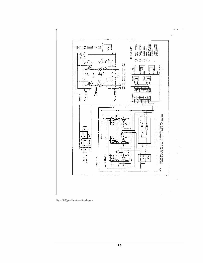
Wiring Control wiring from the station control to the breaker should be installed in accordance with the wiring diagram supplied by Homewood Products. Figure 18 shows a typical wiring diagram. When properly wired according to the wiring diagram, closing the switch on the control panel will apply control power to the breaker operating auxiliaries. Examine relays on the control panel to make sure all paper blocking has been removed. Figure 19 shows a typical breaker wiring diagram of a control scheme employing three pressure switches.
1515
Figure 18 Typical breaker wiring diagram

1616
Figure 19 Typical wiring diagram with three pressure switches

1717
Trial Operation After the breaker unit has been securely bolted to the floor, thoroughly cleaned both inside and out, graphite grease on the moving contacts lower terminal contact bridges removed and replaced with new clean graphite grease, breaker operated by hand with the hand operating lever to check clearances, air connections made (after having blown out to remove foreign material), breaker opened by hand with 30 pounds of pressure to clean out the blast valves and all wiring connections made, the unit is then ready for a final inspection.
A thorough inspection of the breaker should be made to see if any parts have become visibly loosened due to shipment. It should not be necessary to alter any adjustments as final adjustments were made at the factory.
Charge the reservoir to 150 pounds of pressure by opening the cut-off valve at the breaker. Close the valve and slowly drain the reservoir by opening the drain valve located at the bottom of the reservoir on the left side and check the action of the pressure switches located between the control panel and the mechanism. Remove the covers on the switches to note the action of the electrical contact inside each switch. Switch #2, the control switch, should be closed while the pressure is dropping from 150 pounds down to 112 pounds at which point it opens whereas the alarm switch #1 should be open as the pressure drops from 150 pounds down to 120 pounds pressure at which point it closes. Pressure switches will automatically reset when the pressure is raised 15 pounds. After noting the action of the pressure switches, recharge the reservoir to 150 pounds pressure and close the cut-off valve.
If the breaker is equipped with three pressure switches, the alarm switch will close at 120 psi, the control switch will open at 116 psi and the trip switch will close at 112 psi. All the switches will reset when the pressure is raised approximately 15 psi above the settings indicated.
The switch operating points indicated above should be checked using a pressure gauge that has an accuracy of + ½ p.s.i. over the required range. The pressure gauge on the breaker does not have this accuracy.
The switches were set at the factory as close to the nominal setting as possible using a calibrated pressure gauge with a + ½ p.s.i. accuracy. In subsequent checking, using a comparable gauge, the switch operating points may vary + 3 p.s.i. As long as the 120, 116, and 112 p.s.i. operating points do not overlap, no switch adjustment is necessary.
1818
After checking to see that the hand-operating lever is not in its socket, close the switch on the control panel and operate the breaker electrically by pushing the close and trip buttons on the control panel. After two or three tripping operations, the breaker control should be inoperative because the control pressure switch should lock open the electrical control circuits. Recharge the reservoir to 150 pounds of pressure and leave the cut-off valve open. The breaker is now ready to be put in service.
CAUTION: EXPOSED PORTIONS OF COMPRESSED AIR BREAKERS IN THE HIGH VOLTAGE BREAKER COMPARTMENT CARRY LINE POTENTIAL. BEFORE APPLYING POWER TO THE BREAKER SEE THAT NO GROUNDED OBJECTS ARE TOUCHING LIVE PARTS, AND THAT NO TOOLS OR OTHER MATERIALS HAVE BEEN LEFT ON THE BREAKER AT POINTS WHERE THEY MAY FORM A CONNECTION ACROSS POTENTIALS.
Air Supply Unit See that air is shut off from other points in the delivery system where it might cause injury or damage, and that all valves in the system are set to feed the desired point. It is recommended that pressure in the delivery system be raised to 150 pounds before admitting air to the breaker reservoirs.

1919
Operation And Maintenance The following information on adjustments is given as a guide for maintenance and to facilitate the reassembling of parts in case they have been removed for any reason or require replacing at any time.
A definite plan of maintenance will be followed in describing the breaker adjustments so that maintenance personnel may start at the bottom of the breaker and work towards the top of the breaker in progressive steps.
Devices Operated By Compressed Air Reservoir, Air Lines, Safety Valve, and Pressure Gauge
Figure 4 shows the incoming air supply line connected to a check valve. The purpose of the check valve is to allow air to flow into the reservoir but to prevent air flow out of the reservoir in case of a line break between the breaker and the air supply unit. No maintenance or adjustment is anticipated on the check valve or on the compressed air reservoir to which it is connected. Air piping running across the front of the breaker should be securely clamped in place. Air is stored in the reservoir at 150 pounds of pressure. A safety valve set to pop at 165 pounds in case of overpressure and a pressure gauge are supplied. See Figure 9 Maintenance personnel should open the drain valve from the reservoir occasionally to drain off any accumulated moisture.
Chapter
4
2020
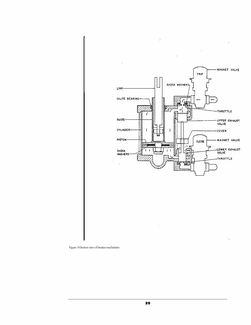
Figure 14 Section view of breaker mechanism

2121
Pneumatic Mechanism and Magnet Valves Figure 4 shows the general location of the mechanism, which is air, operated. Air admitted underneath the piston forces the mechanism piston upwards which causes the breaker contacts to close. Air admitted on top of the piston forces it downward opening the breaker. Figure 14 shows a view of the mechanism during a breaker opening operation. Air is admitted by the trip magnet valve, which is operated electrically, to the top of the piston and to the top of the upper exhaust valve as indicated by arrows. The air pressure forces the piston downward thereby pulling the breaker contacts open. The piston which is composed of two plates separated by shock washers travels to the bottom of the cylinder stopping against the bottom mechanism casting where the shock washers inside the piston plates absorb part of the shock. Shock absorbers connected to the breaker shaft absorb the greater part of the opening effort. Air trapped underneath the piston has a clear path, through opening in the bottom casting as indicated by arrows. To the outside atmosphere. The air pressure forcing the upper exhaust valve downward closes the lower exhaust valve and makes it impossible for air to enter the mechanism underneath the piston until the top trip magnet valve coil is de-energized. Energizing the close magnet valve allows air to flow through the close magnet valve and against the head of the lower exhaust valve. The lower exhaust valve moves upward allowing air to pass in under the mechanism piston which is then pushed upwards causing breaker contacts to close. The upwards motion of the exhaust valve causes the upper exhaust valve to close the air passage from the trip magnet valve to the upper side of the mechanism piston and at the same time provides a path for air trapped above the mechanism piston to be exhausted to outside atmosphere through ports in the upper exhaust valve casting. The piston striking the top mechanism casting stops the upward motion of the mechanism piston. Shock washers between the piston plates plus shock absorbers on the breaker shaft absorb the shock of stopping the mechanism piston.
In case both trip and close magnet valve coils are energized at the same time, the trip magnet valve would take control because the upper exhaust valve head is larger in area than the lower exhaust valve thereby pushing the exhaust valves downward allowing air to flow in on top of the main piston and open the breaker. Air would be prohibited from entering the mechanism underneath the piston because of the lower exhaust valve blocking the air passage between the close magnet valve and the mechanism piston.
The bearing in the top casting of the mechanism provides enough lubrication to keep the guide well oiled. A cover on the lower exhaust valve stem is used to prevent dirt and grit from entering the lower exhaust valve entrance.

2222
If it is desired to dismantle the mechanism in case of trouble, it is suggested that the entire mechanism assembly be removed from the breaker by removing the four long studs that support the mechanism from the breaker frame. This should be done after removing the air lines entering the magnet valves. On some models, the fittings connected to the magnet valves are brazed in place and should not be removed. After removing the four studs holding the top and bottom mechanism castings, the cylinder can be removed and the piston assembly may then be examined. Care should be exercised in removing the piston ring in the upper piston plate. The nut underneath the piston plates may be removed thereby freeing the piston plates and the shock washers. The guide is swedged to a threaded stud at the bottom of the guide that contains the pin holding the mechanism link in place. To reassemble the mechanism, make sure the lower and upper exhaust valves are in place before tightening the four mechanism studs. All other parts may then be assembled as indicated in Figure 14. Maintenance personnel should check to see that the bearing in the top of the mechanism is still furnishing adequate lubrication. Exhaust valves should be free to move when lifted by hand and no binding should exist between the mechanism guide and bearing when operated with the hand-operating lever. No adjustments are required.
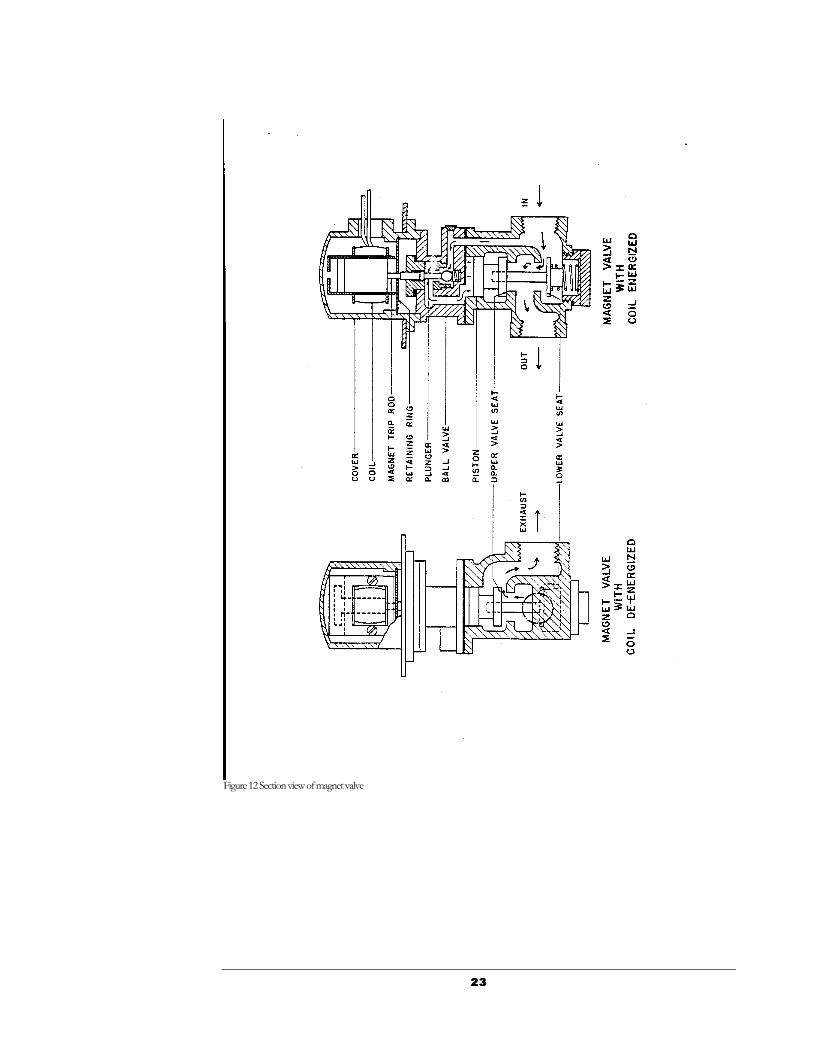
The magnet valves mentioned in the preceding paragraph are shown in detail in Figure 12. Arrows indicate normal flow of air through a valve with the coil energized on the right hand side of Figure 12. The magnet coil, when energized, pushes a magnet trip rod down which causes a plunger to unseat a ball valve allowing air to flow past the ball and push down a piston, as indicated by the small arrows. This causes opening of the lower valve seat and closing of the upper valve seat, which allows air to flow through the valve.
2323
Figure 12 Section view of magnet valve

2424
The view shown on the left side of Figure 12 indicates the flow of air that is trapped between the mechanism and the magnet valve when the magnet valve coil is de-energized. Once the lower valve seat has closed, the upper valve seat opens thus allowing the trapped air to flow in reverse through the valve and out through the upper valve seat to the exhaust port in the valve. The valve has three parts marked in, out, and exhaust. No maintenance is anticipated and no adjustments are required. However, in case of electrical failure, a new coil and magnet assembly may be installed by removing the top cover and retaining ring. In case of mechanical failure, it might be well to first remove the top cover to see if any cuttings or foreign material might have lodged between the plunger and the plunger nut located right beneath the retaining ring. It is not recommended that this be checked as part of a regular maintenance program as the danger of introducing new foreign material is greater than any preventative maintenance that might be accomplished. Trip and close magnet valve coils are identical and interchangeable.
Some breakers may have dual close and trip magnet valves. If this is so, the valve shown in Figure 12 is not used. Figure 13 schematically show the close and trip valve arrangement for breakers equipped for dual close and trip. The total scheme consists of two normally closed solenoid direct operated control valves operating a normally closed pressure operated control valve through a shuttle valve.
Blast Valve The blast valve allows compressed air from the reservoir to pass up the blast tube past the contacts on a breaker opening operation. Figure 15 shows a detailed view of the blast valve and its component parts. Arrows indicate flow of compressed air during a breaker opening operation. During this operation, the breaker shaft rotates counter clockwise allowing the shaft cam to engage a roller on lever A causing the lever to rotate clockwise around pin B. Lever A causes a larger lever C, rotating about pin D, to depress the blast valve nut which opens the blast valve allowing air to flow from the reservoir past the valve and up the blast tube. The blast valve opening should be nominally 3/4 of an inch as indicated in Figure 15 but a variation of plus or minus 1/4 of an inch is permissible. Measuring the distance the blast valve nut is depressed when operating the breaker with the hand-operating lever can check this distance. The breaker shaft continues to rotate counter clockwise on opening until the cam completely clears the rollers and levers A and C drops back to their normal position allowing the blast valve to close. Air pressure against the valve cap plus the blast valve spring keeps the blast valve tightly closed.

2525
Figure 15: Section View of Blast Valve.

2626
Figure 16 Blast valve details

2727
The shaft cam and blast valve levers are designed so that the shaft cam starts to pick up the blast valve levers and partially open the blast valve almost immediately after the shaft begins to rotate on a normal breaker opening operation. By the time the main breaker contacts have parted, the blast valve is open approximately 50% of the full blast valve opening. The breakers are adjusted so that the full blast valve opening, as indicated in Figure 15, 3/4 of an inch when breaker contacts have parted 1-1/2 inches. This adjustment is made because arc interruption normally takes place at some point between contact parting and a contact separation of 1-1/2 inches. Approximately full blast valve opening is maintained until contacts have parted 5 inches or more at which time the blast valve closes.
During a breaker closing operation, the breaker shaft rotates in a clockwise direction until the shaft cam squarely strikes the roller on lever A. The shaft cam causes the roller on lever A to be moved partly downward thereby causing lever A to rotate counter-clockwise about pin B. This allows the shaft cam to pass completely under lever A, due to spring action, immediately resets itself once it becomes mechanically clear of the shaft cam and is once again ready for a normal tripping or breaker opening operation. The breaker has now been closed without opening the blast valve.
The blast valve, in Figure 15, effectively seals off air in the reservoir by the action of the gasket against the blast valve removable body. A flexible “O” ring seals off the air between the removable body and the reservoir while another “O” ring prevents leakage of air along the blast valve rod. If an air leak develops, removing four bolts located near the blast valve nut and then withdrawing the removable body from the valve casting allows for easy replacement of the flexible “O” rings and gasket. Removing the nut and cap from the valve allows the gasket to be removed from the cap. The “O” rings can then be easily removed. If the gasket shows signs of excessive wear, it should be replaced. After replacing the gasket, tighten the spacer “O” ring and cap in place so that an .008-inch feeler gauge will not pass between the gasket and the metal spacer holding the gasket down. The cap assembly should then be replaced in the removable body. The valve-closed gap should be checked at this time using long metal strips filed on one end to meet the tolerance .025-.045 inches specified in Figure 15. It is important that these tolerances be maintained in order that the gasket will properly seal off the air and still not be deformed too much on each valve closing. Reassemble the valve and removable body back in the valve casing and recheck the 3/4-inch valve opening by measuring the depression of the valve nut as the breaker is operated by hand. Levers A and C should operate freely and a gap of 1/32 to 3/16 inch should be obtained between the roller on lever C and the blast valve nut as well as a 1/32 inch minimum clearance between the roller on lever A and the shaft cam when the breaker is in the closed position. Maintenance personnel should check the four bolts near the blast valve nut for tightness
2828
plus two bolts holding the shaft cam in place and should check levers A and C to see that all pins and parts are in place. The valve and removable body need not be removed for routine maintenance inspection unless the gasket is to be replaced due to excessive air leakage. A leak rate of 5 pounds per hour is considered allowable on this type of breaker. To determine the leak rate on a single breaker, charge the reservoir to 150 pounds pressure and turn off the air supply at the cut-off valve in the mechanism compartment. Allow the breaker to stand for 30 minutes and then record the pressure gauge reading. After one hour has elapsed, read the pressure gauge again and the difference in the two readings will indicate the breaker air loss. All adjustments are noted in Figure 15 except 1/32 to 3/16 inch clearance between the roller on lever C and the blast valve nut and the 1/32 inch minimum clearance between the roller on lever A and the shaft cam when the breaker is in the closed position.
Figure 15 does not apply to the 2500 MVA breakers. The blast valve opening should be 5/8 + 1/64 of an inch as shown in Figure 16, and the indicated blast valve openings at parting of the main contacts should be obtained. Plus or minus 1/8 of an inch is permissible for this adjustment. The design shown in Figure 16 does not provide for clearance between a roller on lever C and a blast valve nut, since the blast valve adjusting nut is held captive by lever C. Adjustment of blast valve opening is obtained by removing pin D, then raising the linkage assembly about the blast valve adjusting nut. Raising the linkage assembly, through cam action, lowers the blast valve adjusting-nut-locking plate, permitting the blast valve, adjusting nut to rotate on the blast valve stem. Since the linkage assembly holds the adjusting nut captive, turning the linkage assembly results in blast valve opening adjustment. Clockwise rotation of the linkage reduces valve opening. Adjustment of the point in the breaker opening stroke at which the blast valve starts to open is obtained by loosening the two bolts holding the cam segment to the breaker shaft and moving the cam segment in its serrations. Movement toward the front of the breaker causes the blast valves to open sooner. All other description relative to Figure 15 applies to Figure 16.
Pressure Switches The pressure switches shown in Figure 17 are bellows actuated to “make” and “break” electrical contacts at predetermined pressures.
On breakers with two pressure switches, the switch action is as follows:
The control pressure switch contacts are closed as long as the breaker reservoir pressure is between 112 and 150 pounds, which is the proper range of pressure for efficient breaker operation. However, as soon as the pressure drops below 112 pounds, the control pressure switch contacts open and lock out the electrical control thereby making it impossible to close or trip the breaker

2929
electrically. As soon as the pressure is raised 15 pounds, the control switch resets and breaker operations are again possible.
A second pressure switch, labeled alarm switch, closes its contacts when the pressure drops to 120 pounds and energizes an alarm device (the alarm device is to be supplied by the customer) thereby notifying operators of a low pressure condition. After the pressure has been raised 15 pounds, the alarm switch opens its contacts and de-energizes the alarm circuit. The difference between the pressure at which the contacts first operate and the pressure at which they reset, is approximately 15 pounds and is called the switch differential.
On breakers with three pressure switches, the switch action is as follows:
The trip pressure switch contacts are open as long as the breaker reservoir pressure is between 112 and 150 pounds, which is the proper range of pressure for efficient breaker operation. However, as soon as the pressure drops below 112 pound, the trip pressure switch contacts close tripping the breaker electrically. As soon as the pressure is raised 15 pounds, the trip switch resets.
The control pressure switch contacts are closed as long as the breaker reservoir pressure is between 116 and 150 psi. When the pressure drops to 116 psi, the control pressure switch contacts open and lock out the electrical control so that the breaker cannot be closed. As soon as the pressure is raised 15 psi, the control switch resets.
A third pressure switch, labeled alarm switch, closes its contacts when the pressure drops to 120 pounds and energizes an alarm device (the alarm device is to be supplied by the customer) thereby notifying operators of a low pressure condition. After the pressure has been raised 15 pounds, the alarm switch opens its contacts and de-energizes the alarm circuit.
The switches were set at the factory as close to the nominal settings as possible using a calibrated pressure gauge with a + ½ psi accuracy. In subsequent checking, using a comparable gate, the switch operating points may vary + 3 psi. As long as the 120, 116, and 112 psi operating points do not overlap, no switch adjustment is necessary. If switch adjustment is necessary, refer to Figure 17, Pressure Switches, and the Trial Operation section of this instruction book.

3030
Figure 17: Pressure Switch
A small amount of high-grade light lubricating oil should be put on the pressure switch moving parts every six to twelve months. In the event of removal or replacement, do not turn the switch by grasping the switch case, nor use a pipe wrench on the bellows cup. Use a wrench on the hexagonal shoulder only. Adjustments may be made as previously described.

3131
Control Scheme And Control Panel A typical two pressure switch control scheme is shown in Fig. 18. A rotary 10-pole auxiliary switch operated by a link from the main breaker-operating shaft is used as shown on the left side of Figures 3 and 9 right above the control panel. The control panel is a swinging panel, and Figure 10 shows the availability of wiring for checking on the rear of the panel. The wiring to the pressure switches, magnet valves, interlock and adjacent breakers is carried in a wiring trough. Type MG-6 relays are mounted on the relay panel and are enclosed for protection against dust and dirt. Terminal blocks for the customer’s connections are located on the inside of the left hand breaker side sheet and are readily accessible after swinging the control panel out of the way.

3232
The wiring diagram in Figure 18 is drawn looking into the rear of the panel just the way a maintenance person would see the panel while checking wiring. The general XYZ scheme of control is used. The diagram here is shown for the open position of the breaker contacts and with no air in the reservoir. The purpose of this scheme of control is to insure that an operating impulse having been initiated at the control switch, the proper timing and sequence of valve operations will be carried through without further reference to the control switch. Using the schematic, the sequence of operations is as follows:
To close the breaker, the control switch at the operator’s desk is turned to the “close” position. This energizes the “X” relay which, through its four contacts, seals in and completes the closing magnet valve coil circuit thus initiating the operation of air magnet valves as described under “Pneumatic Mechanism.” Once the “X” relay has sealed in an unsuccessful closing operation due to release of the control switch handle is no longer possible and the closing operation continues regardless of the control switch position.
As the breaker operating shaft rotates toward the closed contact position, the “a” contact on the auxiliary switch closes and energizes the “Y” relay. The “Y” relay picks up and opens the “X” relay circuit and the closing magnet valve coil. At the same time the “Y” relay seals in and maintains the “X” relay in its de-energized state so that in the event of protective line relay action calling for an immediate automatic opening, and attempt to re-close can not be made through the control switch handle which has been held in the “close” position throughout this period. The handle must again be returned to neutral position before a second closing operation can be made.
To open the breaker, the control switch handle is turned to the “trip” position which energizes the “Z” relay. This relay seals in and closes the opening magnet valve coil circuit, initiating the operation of air valves as previously described.
Two pressure switches, all responsive to air pressure in the breaker reservoir, are mounted on a steel panel. Electrical connections for all switches are shown in the wiring diagram. The function of one of these switches is to lock out electrical control when air pressure in the reservoir has been reduced to a point at which it is no longer adequate for arc interruption. This lockout function is necessary because the breaker may be operated mechanically with air pressure lower than that at which it is safe to attempt circuit interruption.
The function of the second switch is to provide an alarm, either audible or visual, at some predetermined point before lockout as a warning to the operator that pressure is becoming low.

3333
When the breaker is locked open by the mechanical and electrical interlock on the pneumatic mechanism, a contact in the closing circuit is opened which prevents closing the breaker electrically as well as mechanically.
In the event that a tripping impulse is received at some time during a closing operation, the following sequence of operations takes place.
The breaker continues to close until the “a” contacts of the 10-pole auxiliary switch close. This energizes the Z relay which seals in and closes the trip magnet valve coil on the pneumatic mechanism thereby initiating a normal breaker opening operation.
Since the time to energize the Z coil and the trip magnet valve coil on the mechanism might be a little less than the time to energize the Y relay, which then de-energizes the close magnet valve coil on the mechanism, there is a possibility that both trip and close magnet valves might attempt to admit air to the mechanism at the same time. This condition is taken care of by the mechanism exhaust valves which gives preference to the trip magnet valve and close the air passage from the close magnet valve to the mechanism. In addition, it is important that the blast valve levers are in the proper position to open the blast valve during the opening operation. This is taken care of by adjusting the 10-pole auxiliary switch “a” contacts to be delayed so as to not complete their circuit until after the blast valve levers have completely reset and are ready for an opening operation. These adjustments are all made at the factory and should not require any changes.
If red and green lights are connected in the control circuit by the customer as indicated on the breaker wiring diagram. The green light will indicate that the breaker is in the open position and the red light will indicate that the breaker is in the closed position. In addition, the red lamp circuit supervises the trip coil, “Z” coil and control pressure switch #2. If the breaker is closed with the red lamp lighted, then the circuit through the red lamp, trip coil, ”Z” coil, and pressure switch is complete. This indicates that all devices in the trip circuit are in condition to trip the breaker. If the breaker is closed and the red lamp is not lighted, then either the red lamp, trip coil, Z coil, or pressure switch is not functioning properly and the breaker may not trip. If the pressure switch is open due to a low pressure condition, the red lamp would fail to light. However, the alarm indication received from the alarm pressure switch #1 should indicate low pressure. If the air pressure is normal (150 pounds) while the breaker is closed and the red lamp is still not lighted, then an inspection of the trip circuit should be made to determine whether the trouble is in the red lamp, trip coil, or the Z coil.
Maintenance personnel should check the control panel, relay contacts, pressure switch contacts, and interlock contacts to see that they are clean. The breaker

3434
should also be operated electrically a few times with the cut off-valve to the breaker reservoir closed in order to test all electrical circuits plus checking to see that the control pressure switch locks out the electrical control when the pressure drops below 112 pounds. Adjustment or setting of the 10-pole auxiliary switch should be checked as follows. With no air in the reservoir, slowly close the breaker by hand and after the blast valve levers reset or snap into position right before the breaker closing operation is complete, check the continuity across the “a” contact on the 10-pole auxiliary switch in the Z coil circuit (contact 6 on the 10 pole auxiliary switch when counted from the lever end of the switch). This contact should still be open. A slight continuation of the breaker contacts towards the closed position should cause the contact to “make” and the circuit will show continuity. This check insures that the blast valve levers are in position to open the blast valve before the trip circuit is “made up” for a normal tripping operation.
Figure 19 shows a typical three pressure switch control scheme. Fundamentally, operation is the same two pressure switch scheme previously described excepting that there are three pressure switches: alarm; control, to block closing the breaker below 116 psi; and trip, to trip the breaker if the pressure drops to 112 psi.
Shock Absorbers Up to eight single acting shock absorbers used to control the speed of the moving contact arm during both the opening and closing operations. The shock absorbers are located above the reservoir with one end being attached to the steel mounting plate directly above the reservoir that separates the high voltage compartment from the mechanism compartment. The other end of each shock absorber is attached to a steel bracket on the main breaker shaft. During a breaker closing operation, compressed air under the mechanism piston imparts an upward push on the piston that causes the breaker shaft to rotate in a direction to close the breaker contacts. Rotation of the shaft also moves the shock absorbers through a compression stroke during which the oil filled shocks offer practically no resistance to movement. Near the end of the breaker closing operation, the bracket on the shaft connected to one end of the shock absorbers goes over center and direction of motion in the absorbers actually changes from compression to recoil. The shock absorber recoil stroke is where the greatest resistance to motion is encountered. This reduces the speed of the moving contact during the last few inches of travel thereby reducing closing impact.
Action of the shock absorbers on a breaker opening operation is just the same as on breaker closing. At the beginning of the breaker-opening stroke, the compression stroke of the absorbers does not hinder the moving contact in

3535
gaining the high speed necessary for efficient interruption. However, as the bracket on the shaft connected to the absorbers again goes over center but in the opposite direction, the shock absorber action changes from compression to recoil which, due to the lengthening of the shock absorbers provides high resistance to motion. The moving arm is then brought to a gradual stop with very little rebound. The maximum allowable rebound on opening is 25% of the breaker-opening stroke. A spring over two of the shock absorbers holds the breaker in the closed or opened position by maintaining the shock absorber shaft bracket over center.
The shock absorbers are oil filled and then sealed so that refilling, servicing, or adjusting is never required. Maintenance personnel should inspect for loose cotter pins and signs of oil leakage. If any leakage is noticed, the defective shock absorber should be replaced. The absorber is mounted on the breaker with the heavy end or end with the protective dust tube cylinder attached to the breaker mounting plate while the small end is attached to the shaft bracket. No adjustment is required.
Hand Operating Lever A hand-operating lever is supplied with each group of breakers in any installation. Designed to be inserted in a linkage connected to the shaft, it permits opening and closing the contacts for maintenance purposes. This handle should not be used for breaker operation when the main contacts are energized from a power source, when the control circuit is energized, or when there is more than 30 p.s.i. in the breaker reservoir.
Mechanism Interlock A mechanical and electrical interlock is mounted in the mechanism compartment. The mechanical interlock consists of a plunger which, when pushed, interferes with a projection on the breaker shaft and prevents the breaker from closing. A key in the electrical interlock, when turned, causes a rod to engage the plunger in the mechanical interlock and permanently locks the breaker open. Turning the key also opens a contact in the electrical closing circuit that effectively locks the breaker open electrically as well as mechanically.
Turning the electrical interlock key in the opposite direction closes a contact in the electrical closing circuit and releases the mechanical interlock plunger. This allows the breaker to close mechanically and electrically when an operator energizes the proper control circuit or when the “close” push button on the control panel is pushed. The interlock is designed to prevent the breaker from

3636
closing and is inoperative if the breaker is already in the closed position. No maintenance and no adjustment should be required.
Pole Unit Assembly The arc chute, upper terminal, contact fingers, moving contact arm, contact bridges, lower terminal, and blast tube, as shown in Figures 3, 5, and 20 are the principal parts of the pole unit assembly. Figure 3 is a sketch showing the location of the parts listed above. Figure 21 is a typical 5000-ampere pole unit.
Arc Chute and Arc Chute Removal The arc chute as indicated in the sketch Figure 3 and photograph Figure 20 is the interrupting device used to aid in extinguishing the high current arcs.
It should not be necessary to disassemble the arc chute completely unless the slots in the splitter plates have eroded excessively as a result of interrupting many faults.
For the areas where the arc has the most contact and intensity, the primary material used for arc chute construction is a hard fiber. This material is self-cleaning under arc action, and the air blast at each opening of the breaker should keep the interior of the chute free from loose dirt.
Even though they show a relatively long life under average switching conditions, the fiber splitter plate will be the first to show erosion under arc action. These are the plates that fan out lengthwise of the chute. Each splitter has a notch or slot cut in its lower end, these notches lining up into a groove through which the moving contact passes.
Splitter plates are held in position in the chute by a row of parallel grooves in the fiber block at the bottom of the chute, and by studs passing through the arc chute sides at the upper end of the splitters. Removing the one stud in each splitter and pulling out from the upper end of the chute disassembles them. The cooler assemblies carrying the cooler plates and screens are disassembled in the same manner. While it is possible to replace one splitter plate at a time without a general dismantling of the chute, it is advisable on replacing any splitter to dismantle the remainder of the chute for inspection. This work is best done with the chute removed from the breaker.
The notch cut in the lower end of each fiber splitter plate is 1-1/4 inches deep when new. Action of the arc over extended periods of time and high current interruptions will cause this slot to burn deeper. When the slot exceeds 2 inches in depth, a new splitter plate should be ordered and installed at the next convenient inspection. On 2500 MVA breakers, the slot in the rear splitter

3737
plate is 2-1/2 inches deep. This plate should be replaced when the slot depth exceed 3-1/4 inches.
The arc chute may be easily removed from the breaker by first removing the interphase barriers separating the phases in the high voltage compartment. Removable covers, as shown in Figure 24 are unbolted from the space above the arc chute on the front of the breaker structure. A removable steel frame angle located in front of each arc chute is then removed. A steel bracket is then bolted to the top of the arc chute and a block and tackle is placed between the top of the arc chute bracket just bolted in place and the top of the breaker cell. The bolts holding the arc chute in place on the breaker are removed and rubber gasket material at the top of the arc chute is removed. The chute can then be moved forward towards the front of the breaker about 1 inch by grasping the top and bottom of the chute at the front edges and moving the chute up and down and pulling forward at the same time. The chute may then be lifted clear of the contacts with the block and tackle and lowered to the ground.
To replace an arc chute, the reverse procedure is followed with the exception that the contact cover located above the contact fingers on the upper terminal must be loosened by loosening the four bolts holding the cover casting in place. This allows the arc chute to slide into place. The cover casting is then pushed tight against the arc chute and the bolts tightened after the three bolts holding the arc chute in place have been replaced. An option to the above method is to remove the contact cover completely. Then it can be placed on the arc chute prior to arc chute installation on the pole unit. Results may vary from method to method.
Maintenance personnel should inspect the depth of the slots in the fiber splitter plates. The arc chute should not need to be removed to perform this inspection. This can be determined through visual inspection. No adjustments are necessary.
Stationary Contact (Upper terminal and contact fingers) The stationary contact structure consists of the contact fingers bolted to the upper terminal as shown in Figure 23. The contact fingers receive the moving contact arm at the open end of the fingers which causes the contact fingers to open slightly when the moving contact enters. The contact fingers, acting like a tuning fork, hold the moving arm tight due to the action of the fingers in trying to resume their normal position. The contact fingers make a line contact instead of a flat surface contact on all six fingers.
Figure 23 shows the method of bolting the contact fingers to the upper terminal in case of replacement. A special wrench made of 3/8 inch hexagonal steel bar and approximately 18 inches long welded to a short handle partially hidden in the workman’s hands in the illustration is used for tightening the

3838
Allen head bolts holding the contact fingers to the upper terminal casting. The arc chute must be removed in order to change or replace contact fingers.
On 5000-ampere breakers, the stationary contact fingers bolt to the upper contact terminal casting from the rear. No special tool is required.
Maintenance personnel, in replacing contact fingers, should allow the moving arm to align the contact fingers before tightening the bolts holding the contact fingers in place. No adjustments required except the aligning method just mentioned.
Moving Contact The moving contact, as shown in Figure 3, rotates about a hinge pin. The upper end of the contact engages the contact fingers and the lower end furnishes a surface for one end of the contact bridge to ride on. Figure 5 shows all three moving contact arms while Figure 20 shows the details of the contact bridge construction at the lower end of the moving arm. All contact surfaces are silver-plated and in addition, an arc tip of an arc resistant material is brazed in the upper end of the moving contact. Current is normally carried on the silver plated faces at the upper end of the moving arm where it makes engagement with the contact fingers. During current interruption, the arc is transferred from the normal current carrying surfaces to the arc tip and remains there until interruption takes place. This allows the normal current carrying surfaces to remain in good condition to carry load current. At the lower end of the moving arm, the contact bridge which consists of a hard copper bar with silver blocks brazed on each end, rides on the curved silver plated surface of the moving contact. Springs pushing the contact bridge against the moving arm and lower terminal maintain high contact pressure. The silver plated lower terminal makes contact with the silver block brazed on the contact bridge to complete the current path from the moving contact arm through the contact bridge to the lower terminal. A thin layer of graphite grease should be applied to each end o f the moving arm for lubrication purposes.
Maintenance personnel should check the alignment of the moving contact arm as it enters the contact fingers at the upper end of the moving arm. Wipe off the old graphite grease and apply a thin layer of new graphite grease at both the upper and lower end of the moving arm. Any roughening of the silver contact surfaces at the upper end of the moving contact such as deep scratches may be smoothed out with a fine and very flat file. Care must be observed, as the silver plating is only .003 inch thick. Sandpaper, emery cloth, or steel wool is not recommended for this purpose. No adjustments are required.
Operating Rod, Blast Tube, and Supports The operating rod connects the moving contact arm to the breaker shaft as indicated in Figure 4. The rod is made of a high grade wood micarta with wire

3939
wound metal rod ends on each end. Sufficient creepage distance along the surface of the micarta is allowed to properly protect against voltage breakdown between parts at 13,800 volts and parts at ground potential.
The blast tube is made of insulation selected for its excellent dielectric quality plus its resistance to mechanical shock. The insulating posts to the rear of the blast tube aid in supporting the weight of the arc chute and also provide additional support for the upper terminal casting.
Maintenance personnel should keep all insulating materials free from accumulations of dirt and dust. Loose dust may be blown off with dry compressed air, cleaned with a vacuum cleaner, or wiped with a clean dry cloth. Steam waste is not recommended for this purpose due to its tendency to leave a residue of lint on insulation surfaces. The nut on the lower end of the operation rod should be checked for tightness. No Adjustments required.
Door Interlocks Door interlocks are supplied to protect personnel from opening the doors to the high voltage compartment without first having opened the disconnects and obtained key to the doors. Upon obtaining the proper key, the center door to the high voltage compartment may be unlocked and opened. After opening the center door, each end door may then be opened.
Only the center door has a kirk-key lock. There are locking bars connecting each end door to the center door. With the center door locked, the end doors are also locked.
Maintenance personnel should oil all pins on the interlocking bars. No adjustments are required.
Inspection Check List Periodic inspections of the circuit breaker should be made and the frequency of these inspections should be borne in mind that to secure the protection for which the breaker is installed, the mechanism must be kept in the best of operating condition at all times. It should be given something more than perfunctory inspection. As some exposed parts of the breaker are at line potential, the circuit should be so arranged as to permit isolating the breaker for inspection purposes in order that a complete check may be made.
The frequency of inspection, cleaning, etc. will depend upon the activity and the duty to which the breaker is subjected, and upon the cleanliness of the atmosphere and surroundings of the breaker. For compressed air circuit

4040
breakers, it is recommended that a preliminary or visual inspection be made every year. . When breaker activity is high or where atmospheric conditions are dirty, inspections should be made more frequently. When a breaker has been subjected to automatic openings on unusually high short-circuit currents, it should be given a preliminary inspection.
On any inspection, the following points should be noted in particular:
1. Inspect the breaker structure in general to see that all bolts, nuts and setscrews are tight, that all cotters are in place, etc., as well as to note evidences of excessive wear or of improper operation of the various parts.
A light application of lubricating oil to the pin connected joints will result in smoother operation of the moving parts, and materially reduce wear on the pins. Grease fittings are proved for the greasing of the shaft bearings.
2. Examine pneumatic mechanism for loose bolts at both the top and the bottom. The guide should be checked for lubrication. Exhaust valves (Figure 8), should be free when moved by hand. Oilite bearing should be flush with the top of the mechanism casting. There should be no noticeable friction when the breaker is operated with the hand-closing lever.
3. Observe wiring to see that the insulation has not worn where the wiring from the control panel, pressure switches, magnet valves, or interlock enters the wiring trough. Check the control panel to see that all relays are operating properly.
4. Shock absorbers should be examined for leaks. Replace leaking shock absorbers.
5. The auxiliary switch covers should be removed and the contacts should be checked for proper condition and operation. On switch #1 (top left), number six from the right hand or lever end should be checked as follows: Slowly close the breaker with the hand operating lever and notice when the blast valve levers have completely reset so as to be ready for an opening operation. At this point, contact on pole six on the auxiliary switch should still be open. However, any additional movement of the breaker towards the breaker closed position will cause contact on pole six to close.
6. With no air in the breaker reservoir, open and close the breaker with the hand-operating lever and watch the operation of the blast valve linkage (Figure 15). See that a minimum clearance of 1/32 inch between the shaft cam and the roller on lever A exists as well as 1/32 inch to 3/16 inch clearance between roller on lever C and the blast valve nut when the breaker is in the closed position. The blast valve opening travel should be 3/4 inch, plus or minus 1/8 inch, as measured by the movement of the adjusting nut when the breaker

4141
arcing contacts (not the main contacts) have parted about 1-1/2 inches. The blast valve should close after the breaker arcing contacts have parted 5 inches or more.
For 2500 MVA breakers, the blast valve arrangement is slightly different than other models. Refer to Figure 16 and proceed as follows:
Open and close the breaker with the hand-operating lever and watch the operation of the blast valve linkage. See that a minimum clearance of 1/32 to ¾ inch between the shaft cam and the roller on lever A exists when the breaker is in the closed position. The blast valve opening travel should be 5/8 inch, plus or minus 1/64 of an inch, as measured by the movement of the adjusting nut when the breaker arcing contact (not the main contacts) have parted about 1-1/2 inches. The blast valve should close after breaker arcing contacts have parted 5 inches or more.
7. Examine the moving contact arm for evidence of undue burning on the surfaces making contact with the stationary contact fingers at the upper end and the contact bridges at the lower end (Figure 3). A fine file may be used to dress or smooth the contact surfaces but care should be observed, as the silver plating is only .003 inches thick. All moving contacts should touch the stationary contact fingers upon breaker closing within 1/8 inch of each other. The arcing contacts should enter the contact fingers 2-1/4 to 2-1/2 inches. Contact separation in the breaker open position is 13 to 15 inches. Stationary contact fingers may be examined for undue burning with a flashlight through the open slot in the front of the arc chute. Contact bridges at the lower end of the moving arm should be examined to see that they are still in their proper position.
On 4000-ampere contacts, the moving main contacts should penetrate the stationary contact fingers 7/8 + 1/8 of an inch. See Figure 22. On 5000 ampere (2500 MVA) contacts, the moving main contacts should penetrate the stationary fingers ¾ + 1/16 of an inch. The arcing contact will penetrate 2-3/4 to 3 inches.
8. The arc chute should be examined to determine how deep the fiber plates have burned. This should be done as explained in the section on arc chutes.
9. Door interlocks should be tested to make sure that the end doors will not open unless the center door is unlocked and opened.
10. Fill the reservoir with compressed air. After making sure the hand-operating lever has been removed from the breaker, operate the breaker electrically by pushing the buttons marked “close” and “trip” located on the control panel. On a normal closing operation, the pressure gauge should drop from 150 down to 147 pounds of pressure. On a normal tripping or opening operation,

4242
the pressure gauge should drop from 150 down to 124 pounds. A variation of plus or minus 4 pounds is allowable on a tripping operation and plus or minus 2 pounds on a closing operation. This is the best indication of overall breaker performance.
11. Observe moving contact arms for excessive bounce on an opening operation. No bounce is the most desirable condition, but bounce up to 25% of the total opening stroke is permissible.
12. With air in the reservoir, check the safety valve, which is on the same air line as the pressure gauge, by pulling the stem several times to insure that it is working properly.
13. Remove the covers from the alarm and control pressure switches and exhaust the air from the reservoir slowly. The cut-off valve on the breaker should be closed and the drain valve on the left side of the breaker at the front should be opened. Note the gauge pressure at which the contacts make or break. The alarm switch should close its contact when the pressure has dropped to 120 pounds while the control switch should open its contact when the pressure has dropped to 112 pounds. All switches have a reset differential of 15 p.s.i.
14. Open the reservoir drain valve to remove any moisture that may have collected.
15. Again, operate the breaker several times with the air to see that all parts are working properly.
16. An air leak test, as explained in the section on blast valves in part four, may be made if desired in order to detect leaks greater than 5 pounds per hour.