C4I Afloat Networks Architecture - Purdue University Afloat...C4I Afloat LAN Architecture 28 May...
78
C4I Afloat LAN Architecture 28 May 2004 23 July 2004 DISTRIBUTION STATEMENT: Distribution authorized to the Department of Defense and U.S. DoD contractors only; other requests shall be referred to SPAWAR, PMW 165.
Transcript of C4I Afloat Networks Architecture - Purdue University Afloat...C4I Afloat LAN Architecture 28 May...
C4I Afloat LAN Architecture
28 May 2004
23 July 2004
DISTRIBUTION STATEMENT: Distribution authorized to the Department of Defense and U.S. DoD contractors only; other requests shall be referred to SPAWAR, PMW 165.

C4IAL ARCHITECTURE 23 July 2004
This page intentionally left blank.
C4IAL ARCHITECTURE 23 July 2004
SIGNATURE PAGE Prepared by: Vince Piarulli, PIRAD Technologies /X-Feds, Inc. Jeffrey Smith, SAIC Michael Farrell, SAIC Daniel Deaton, SAIC Jesse Davis, G2SS Jim Ciocco, Booz-Allen-Hamilton
Approved______________________________________________Date______________ Mr. Nicholas Frieje PMW 165-3 Naval Afloat Networks Chief Engineer Program Executive Office C4I and Space
i
C4IAL ARCHITECTURE 23 July 2004
C4I Afloat LAN Architecture
Executive Summary
C4I Afloat Local Area Network (C4IAL) is a Chief of Naval Operations (CNO) sponsored program under the cognizance of the Program Executive Office for C4I and Space (PEO C4I & S). PMW 165 has been tasked to develop the Command and Control, Communications, Computers, Intelligence, Surveillance and Reconnaissance (C4ISR) requirements with underlying architecture to support C4IAL for all operational environments. This document covers the Integrated Shipboard Information System (ISNS) Increment 1 and Submarine Local Area Network (SUBLAN) 1.
The C4IAL Architecture is being developed to define the capabilities needed to support the requirements documented in the C4IAL Operational Requirements Document (ORD). The architecture assists acquisition/program managers in understanding, comparing and analyzing the capabilities required to conduct the C4IAL Mission and ensure interoperability with other Naval and Joint information systems.
The principles and guidelines contained in DoD Architecture Framework (DoDAF), v1.0 defines a coordinated DoD-wide approach for C4ISR architecture development, presentation, and integration. The C4IAL Architecture is being developed in accordance with DoDAF v1.0. The main body of the C4IAL Architecture describes the three views of an architecture and their associated architecture products that are inter-related as described below.
The Operational View (OV) describes the operational concept for the architecture. It identifies process and information requirements in an operational setting. The OV focuses on the mission requirements, activities, and information exchange requirements of the C4IAL. The associated architecture products developed with the OV are:
• OV-1: High-Level Operational Concept Graphic
• OV-2: Operational Node Connectivity Description
• OV-3: Operational Information Exchange Matrix
• OV-5: Operational Activity Model
• OV-6c: Operational Event/Trace Description.
The Systems View (SV) describes “how” the process and information requirements identified in the OV are to be implemented. This iteration of the SV focuses on functionality of systems, and depicts how multiple systems link and integrate based upon the capabilities and operation of particular systems within the architecture. Systems Nodes are defined as nodes that support the operations of operational nodes. The associated architecture products developed with the SV are:
ii
C4IAL ARCHITECTURE 23 July 2004
• SV-1: Systems Interface Description
• SV-2: Systems Communication Description
• SV-4: Systems Functionality Description
• SV-5: Operational Activity to Systems Function Traceability Matrix
• SV-6: Systems Data Exchange Matrix.
The Technical View (TV) identifies the standards to support interoperability interfaces. The associated architecture product developed with the TV is:
• TV-1: Technical Standards Profile.
The Operational Activities and associated IERs developed for the OV are used to develop the system functions in the SV. System functions are defined as specifically those functions done by hardware and/or software that contribute directly and indirectly to the accomplishment of Operational Activities. The system functions identified in the SV are used to identify the applicable interface standards defined by the TV.
The All-Views (AV) products identify and gather some overarching aspects of the architecture that relate to all three views. The AV products provide information relevant to the entire architecture but do not represent a distinct view of the architecture. AV products set the scope and context of the architecture. The scope includes the subject area and time frame for the architecture. The setting in which the architecture exists comprises the interrelated conditions that compose the context for the architecture. The two All-Views products in this architecture are:
• AV-1: Overview and Summary Information
• AV-2: Integrated Dictionary
iii

C4IAL ARCHITECTURE 23 July 2004
This page intentionally left blank.
iv
C4IAL ARCHITECTURE 23 July 2004
Table of Contents
Section Page
1 INTRODUCTION ...................................................................................... 1-1 1.1 PURPOSE ................................................................................................................... 1-1 1.2 BACKGROUND........................................................................................................... 1-1 1.3 SCOPE ....................................................................................................................... 1-1 1.4 DOCUMENT ORGANIZATION...................................................................................... 1-2
2 ARCHITECTURE DEVELOPMENT ..................................................... 2-1
3 OPERATIONAL VIEW (OV) .................................................................. 3-1 3.1 INTRODUCTION ......................................................................................................... 3-1 3.2 SCOPE ....................................................................................................................... 3-1 3.3 C4IAL OV DEVELOPMENT PROCESS........................................................................ 3-1 3.4 OV PRODUCTS.......................................................................................................... 3-2
3.4.1 High-Level Operational Concept Graphic (OV-1)................................................... 3-2 3.4.2 Operational Node Connectivity Description (OV-2)................................................ 3-3 3.4.3 Operational Information Exchange Matrix (OV-3).................................................. 3-4 3.4.4 Organizational Relationships Chart (OV-4) ............................................................ 3-9 3.4.5 Operational Activity Model (OV-5).......................................................................... 3-9 3.4.6 Operational Event/Trace Description (OV-6c) ...................................................... 3-11
4 SYSTEMS VIEW (SV) .............................................................................. 4-1 4.1 INTRODUCTION ......................................................................................................... 4-1 4.2 SCOPE ....................................................................................................................... 4-1 4.3 C4IAL SV DEVELOPMENT PROCESS ........................................................................ 4-1 4.4 SV PRODUCTS........................................................................................................... 4-2
4.4.1 Systems Interface Description (SV-1)....................................................................... 4-2 4.4.2 Systems Communications Description (SV-2) .......................................................... 4-3 4.4.3 Systems Functionality Description (SV-4)................................................................ 4-4 4.4.4 Operational Activity to Systems Function Traceability Matrix (SV-5)..................... 4-8 4.4.5 Systems Data Exchange Matrix (SV-6) .................................................................. 4-13
5 TECHNICAL VIEW (TV) ........................................................................ 5-1 5.1 INTRODUCTION ......................................................................................................... 5-1 5.2 SCOPE ....................................................................................................................... 5-1 5.3 C4IAL TV DEVELOPMENT PROCESS ........................................................................ 5-1 5.4 TV PRODUCTS .......................................................................................................... 5-1
APPENDIX A REFERENCES ................................................................................ A-1
APPENDIX B POINTS OF CONTACT................................................................. B-1
APPENDIX C OVERVIEW AND SUMMARY INFORMATION (AV-1) AND INTEGRATED DICTIONARY (AV-2) ........................................ C-1
APPENDIX D ADDITIONAL SYSTEMS COMMUNICATIONS DESCRIPTIONS (SV-2)................................................................. D-1
v
C4IAL ARCHITECTURE 23 July 2004
List of Figures
Title Page
FIGURE 1. HIGH-LEVEL OPERATIONAL CONCEPT GRAPHIC (OV-1) ...... 3-2
FIGURE 2. OPERATIONAL NODE CONNECTIVITY DESCRIPTION (OV-2)3-3
FIGURE 3. OPERATIONAL ACTIVITY MODEL (OV-5)- PROTECT INFORMATION SYSTEMS........................................................... 3-9
FIGURE 4. OPERATIONAL ACTIVITY MODEL (OV-5)- MANAGE MEANS OF COMMUNICATING OPERATIONAL INFORMATION........ 3-10
FIGURE 5. OPERATIONAL EVENT/TRACE DESCRIPTION (OV-6C).......... 3-11
FIGURE 6. SYSTEMS INTERFACE DESCRIPTION (SV-1)................................ 4-3
FIGURE 7. FORCE LEVEL NETWORK SEGMENT, SYSTEMS COMMUNICATIONS DESCRIPTION (SV-2) ............................ 4-4
FIGURE 8. SYSTEMS FUNCTIONALITY DESCRIPTION (SV-4) - ENTERPRISE SUPPORT SERVICES.......................................... 4-5
FIGURE 9. SYSTEMS FUNCTIONALITY DESCRIPTION (SV-4) - ENTERPRISE SYSTEM SERVICES............................................ 4-6
FIGURE 10. SYSTEMS FUNCTIONALITY DESCRIPTION (SV-4) NETWORKING BREAKDOWN................................................... 4-7
FIGURE 11. SYSTEMS FUNCTIONALITY DESCRIPTION (SV-4)-MANAGE NETWORK OPERATIONS BREAKDOWN ............................... 4-8
FIGURE 12. UNIT LEVEL UNCLASSIFIED NETWORK SEGMENT, SYSTEMS COMMUNICATIONS DESCRIPTION (SV-2) ........................... D-1
FIGURE 13. UNIT LEVEL SECRET NETWORK SEGMENT, SYSTEMS COMMUNICATIONS DESCRIPTION (SV-2) ........................... D-2
FIGURE 14. SUB UNCLASSIFIED NETWORK SEGMENT, SYSTEMS COMMUNICATIONS DESCRIPTION (SV-2) ........................... D-3
FIGURE 15. SUB SECRET NETWORK SEGMENT, SYSTEMS COMMUNICATIONS DESCRIPTION (SV-2) ........................... D-4
vi
C4IAL ARCHITECTURE 23 July 2004
List of Tables
Title Page
TABLE 1. INFORMATION EXCHANGE REQUIREMENTS (IER) (OV-3) ...... 3-5
TABLE 2. OPERATIONAL ACTIVITY TO SYSTEMS FUNCTION TRACEABILITY MATRIX (SV-5)........................................................... 4-9
TABLE 3. C4IAL SYSTEMS DATA EXCHANGE MATRIX (SV-6) .................. 4-15
TABLE 4. C4IAL TECHNICAL STANDARDS PROFILE (TV-1) ......................... 5-2
TABLE 5. C4IAL OVERVIEW AND SUMMARY INFORMATION (AV-1)...... C-1
TABLE 6. INTEGRATED DICTIONARY (AV-2) - PART I ................................. C-4
TABLE 7. ACRONYM LIST (AV-2) - PART II .................................................... C-11
vii

C4IAL ARCHITECTURE 23 July 2004
This page intentionally left blank.
viii
C4IAL ARCHITECTURE 23 July 2004
1 INTRODUCTION
Department of Defense Instruction (DoDI) 5000.2 requires information interoperability and C4I Support that dictates an Integrated Architecture (IA) composed of Operational, Systems, and Technical Views. The IA is to be developed as prescribed in Chairman of the Joint Chiefs of Staff Instruction (CJCSI) 6212.01C, and uses the products described in DoD Architecture Framework (DoDAF), Version 1.0. Accordingly, the C4IAL Architecture is a baseline document that is developed using the principles and guidelines in DoDAF, v1.0. The main body of the C4IAL Architecture document describes the three views of the architecture. The supporting appendices provide a more detailed view of information in the main body.
1.1 Purpose
The C4IAL Architecture is being developed to define the capabilities needed to support the requirements documented in the C4IAL Operational Requirements Document (ORD). The architecture will assist acquisition/program managers in understanding, comparing and analyzing the capabilities required to conduct the C4IAL Mission and ensure interoperability with other Naval and Joint information systems.
1.2 Background
The DoD has established a comprehensive process to improve its ability to execute both traditional and non-traditional missions. Rapid advances in technology require a continuous review of force structure, operational concepts, and acquisition and maintenance of its forces and systems.
The Clinger-Cohen Act of 1996 and the Information Technology Management Reform Act (ITMRA) of 1993 require DoD organizations to measure the performance of existing and planned information systems. In response to this, the Office of Assistant Secretary of Defense for Networks for Information Interoperability (OASD NII) and the Joint Staff (J6) jointly developed the DoDAF, v1.0, which directs the means for developing, evolving and maintaining DoD information systems.
1.3 Scope
The C4IAL Architecture addresses the entire afloat network between its boundaries from the peripheral drop (i.e., computers, printers, servers and other network-connected devices) to the Automated Digital Network System (ADNS).
Department of Defense Architecture Framework, Version 1.0 (DoDAF, v1.0) describes information technology architecture in terms of three architectural views - Operational, Systems and Technical. It also describes the format for all architecture products
1-1
C4IAL ARCHITECTURE 23 July 2004
contained in this architecture. The specified architecture products have been developeto support this stage of the C4IAL acquisition. As the program progresses to furthiterations, additional products may be developed. Chairman, Joint Chiefs of Staff Instruction (CJCSI) 3170.01C outlines the role and functions of these three views and provides the pr
d er
ocess for addressing interoperability issues through the development of critical IERs.
used to identify the applicable interface standards defined by the Technical View (TV).
e operational requirements, activities, and information exchange needs of the C4IAL.
oD system requirements for elements such as security, interoperability, and reach-back.
s. re
based, common building blocks are established, and product lines are developed.
the
C, Overview and Summary
Information (AV-1) and Integrated Dictionary (AV-2).
1.4 Document Organization
sses
t process for the
view, and the various architecture products developed with the view.
The C4IAL Architecture views are inter-related. The operational activities and associated IERs developed for the Operational View (OV) are used to develop the systemfunctions in the Systems View (SV). System functions are defined as specifically those functions done by hardware and/or software that contribute directly and indirectly to the accomplishment of Operational Activities. The system functions identified in the SV are
The OV focuses on th
The SV describes “how” the process and information requirements identified in the OV are to be implemented. The SV also identifies and depicts the D
The TV identifies the “building code” (standards) to support interoperability interfaceThe TV provides the technical guidelines upon which engineering specifications a
There are two additional products called All Views (AV-1 and AV-2). AV-1 contains a general overview and summary information about the purpose, scope, and context ofarchitecture. AV-2 is an Integrated Dictionary that provides a central source for all definitions of Operational Nodes and Systems Nodes referenced in this Architecture.Both the AV-1 and the AV-2 are provided in Appendix
Section 2 of this document discusses the architecture development, Section 3 discuthe OV, Section 4 discusses the SV, and Section 5 discusses the TV of the C4IAL Architecture. Within these three sections, there is an introduction to the respective viewto be discussed, the scope of the view, a discussion of the developmen
1-2
C4IAL ARCHITECTURE 23 July 2004
2 ARCHITECTURE DEVELOPMENT
During the development process of the C4IAL Architecture, the following elements have been developed to support the OV products:
• Systems Nodes: Systems nodes support the operations of the network.
• Operational IERs: Relationships that identify who exchanges what information with whom, why the information is necessary, in what manner, and how and when the exchange occurs. The Operational IERs define the exchanges from/to operational activities. Also identified are the attributes of the information exchange.
• Operational Activities: The set of activities that accomplish the Joint Tasks stated in the Universal Joint Task List (UJTL) for C4ISR applications. The UJTLs were analyzed, refined, and combined into operational activities for application to the C4IAL functional design.
The above elements result from the development of the OV. From the information contained in the OV, the following SV elements are created to support the SV products:
• System Functions: System functions are developed to enable translation of Operational Activities to systems and to establish linkages to Command Nodes and the appropriate Systems Node(s) within each Operational Node.
• System Function Data Exchange: Similar to Operational IERs described above except the information exchange is defined between system functions instead of Operational Activities.
From the SV, the following TV elements are derived to support the TV products:
• Standards: The system functions are defined at a level such that standards can be identified. Once the standards are identified, they are reviewed against the standards within the Joint Technical Architecture (JTA) for compliance and/or compatibility, including the interfaces in the Global Information Grid (GIG). These interfaces are called Key Interface Parameters (KIPs). For the C4IAL, the TV was developed using both the JTA service model and the GIG KIP framework.
All of the elements described above are used to create the architecture products, are inter-related, and can be traced for each Operational Node. Each Operational Node is linked to the operational activities that apply to that Operational Node or Nodes. The IERs for each Operational Node are also identified. The operational activities are then traced to the System Functions for subsequent linking to the Systems Nodes. System Function IERs are also developed, attributed, and documented as an extension of the Operational IERs. System Functions are analyzed to determine the appropriate interoperability interface standards.
2-1

C4IAL ARCHITECTURE 23 July 2004
This page intentionally left blank.
2-2
C4IAL ARCHITECTURE 23 July 2004
3 OPERATIONAL VIEW (OV)
3.1 Introduction
The Operational View (OV) describes “what” is to be built. It identifies process and information capabilities. The purpose of the OV is to provide a dynamic, updateable, standardized roadmap that clearly articulates DoD’s interdisciplinary joint combat capabilities and the relationships among these capabilities required to successfully conduct afloat operations.
3.2 Scope
The OV describes the C4IAL services, the tasks performed by those services, and the information exchange requirements between those services. The development of the OV resulted in these products:
• OV-1: High- Level Operational Concept Graphic depicting the high level command nodes envisioned for C4IAL
• OV-2: Operational Node Connectivity Description depicting the operational nodes and node connectivity (need lines) of the C4IAL
• OV-3: Operational Information Exchange Matrix depicting IERs for each need line of the OV-2.
• OV-5: Operational Activity Model showing the operations that are normally conducted in the course of achieving a mission or a business goal.
• OV-6c: The Operational Event/Trace Description describes timing and sequencing behavior in the operational view.
An OV-4 Organizational Relationships Chart was not produced for this architecture since C4IAL is an infrastructure system not reflective of and irrelevant to organizational or command relationships.
3.3 C4IAL OV Development Process
The C4I Afloat LAN Operational Requirements Document (ORD) was reviewed. Information Exchange Requirements (IERs) were identified as the basis for the Joint Mission Area (JMA) critical IERs based on the format defined by CJCSI 6212.02C. These IERs have performance measures with an underlying C4I set of attributes. In turn, these attributes determine the criticality of an IER based upon whether or not an IER will severely and adversely affect the C4IAL mission if not accomplished. These JMA critical IERs, with their attributes, make up the IER matrix that is used to support the required Interoperability Key Performance Parameters
3-1
C4IAL ARCHITECTURE 23 July 2004
(KPP) located in the Information Dissemination Management (IDM) Capstone Requirements Document (CRD) Requirements checklist in the C4IAL ORD consolidated appendix.
3.4 OV Products
3.4.1 High-Level Operational Concept Graphic (OV-1)
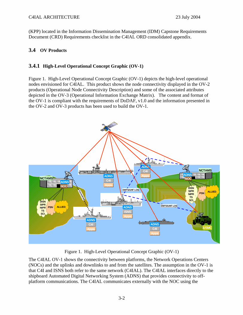
Figure 1. High-Level Operational Concept Graphic (OV-1) depicts the high-level operational nodes envisioned for C4IAL. This product shows the node connectivity displayed in the OV-2 products (Operational Node Connectivity Description) and some of the associated attributes depicted in the OV-3 (Operational Information Exchange Matrix). The content and format of the OV-1 is compliant with the requirements of DoDAF, v1.0 and the information presented in the OV-2 and OV-3 products has been used to build the OV-1.
DWTS/UHF LOS
NCTAMSADNS
ADNSC4I
Apps
DWTS/UHF LOS
NOC
ADNSC4I
Apps
ADNSISNSApps
ADNSC4I
Apps
PSN
ADNSC4I
Apps
ALLIEDDISNSIPRNIPRTSSCI
NCTAMSADNSNOC
DISNSIPRNIPRTSSCI
PSN ALLIED
Terrestrial
USMC
Figure 1. High-Level Operational Concept Graphic (OV-1)
The C4IAL OV-1 shows the connectivity between platforms, the Network Operations Centers (NOCs) and the uplinks and downlinks to and from the satellites. The assumption in the OV-1 is that C4I and ISNS both refer to the same network (C4IAL). The C4IAL interfaces directly to the shipboard Automated Digital Networking System (ADNS) that provides connectivity to off-platform communications. The C4IAL communicates externally with the NOC using the
3-2
C4IAL ARCHITECTURE 23 July 2004
protocol specified in each IER to successfully achieve each IER. The C4IAL is dependent on the ADNS network layer functions for successful IERs, but the NOC (not ADNS) interacts with the C4IAL using the protocols specified in the IERs. The term “Apps” in the OV-1 refers to external systems. The external systems are only provided network connectivity services and are therefore not representing operational IERs, and there are therefore no corresponding IER lines in the OV-3. Further, there is no Multi-Level Security (MLS) across networks. The C4IAL Operational Requirements Document (ORD) specifically requires a “physically separate” network.
3.4.2 Operational Node Connectivity Description (OV-2)
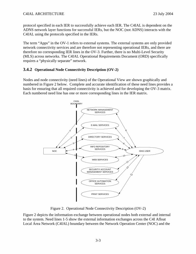
Nodes and node connectivity (need lines) of the Operational View are shown graphically and numbered in Figure 2 below. Complete and accurate identification of these need lines provides a basis for ensuring that all required connectivity is achieved and for developing the OV-3 matrix. Each numbered need line has one or more corresponding lines in the IER matrix.
ISNS USER
NETWORK MANAGEMENT SERVICES
PRINT SERVICES
WEB SERVICES
INFO REPOSITORYSERVICES
E-MAIL SERVICES
1
2
4
5
67
13
10
9
C4IAL BOUNDARY
NOC
DIRECTORY SERVICES
SECURITY/ ACCOUNTMANAGEMENT SERVICES
OFFICE AUTOMATIONSERVICES
3
11
12
8
Figure 2. Operational Node Connectivity Description (OV-2)
Figure 2 depicts the information exchange between operational nodes both external and internal to the system. Need lines 1-5 show the external information exchanges across the C4I Afloat Local Area Network (C4IAL) boundary between the Network Operation Center (NOC) and the
3-3
C4IAL ARCHITECTURE 23 July 2004
C4IAL network management services, email services, directory services, information repository services and web services. Need lines 6-12 represent internal information exchanges between the C4IAL end user and the network services (Network Management Services, email services, directory services, information repository services, web services, office automation services and security/account management services.) Need line 13 indicates the information exchange by which C4IAL users access print services. The NOC refers to the functionality provided at the shore termination points for C4IAL. The eventual end point for many of the information exchanges is an external node beyond the NOC (to include the submarine Broadcast Control Authority (BCA)). However, the C4IAL architecture boundary is the exchange between the NOC and the afloat node.
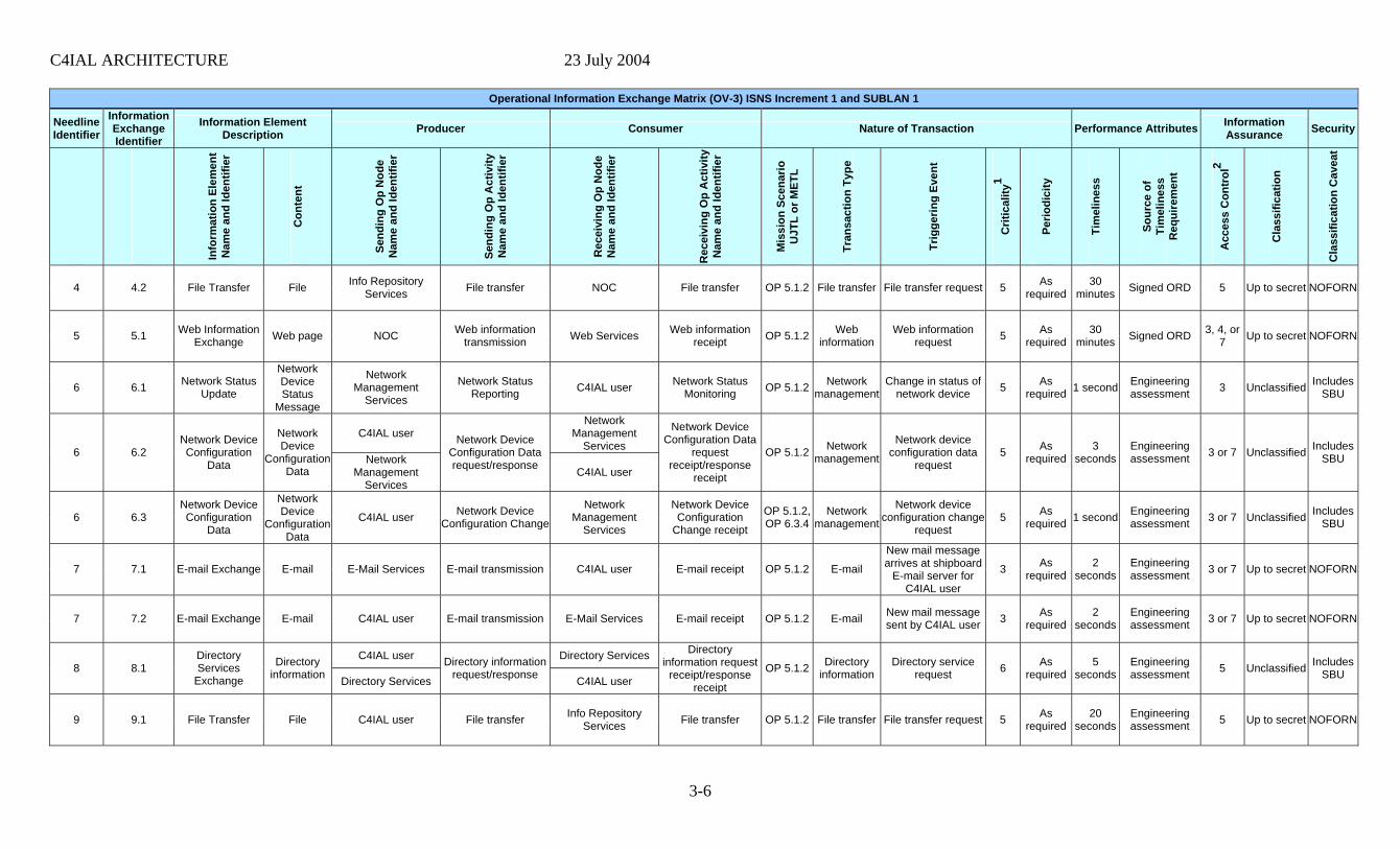
3.4.3 Operational Information Exchange Matrix (OV-3)
Information Exchange Requirements (IERs) in the Operational Information Exchange Matrix (OV-3) are predicated upon the:
• Task being performed (based upon the Universal Joint Task List)
• Event or action that “triggers” the information to be exchanged
• Information characterization (of the information that is being exchanged)
• Sending and receiving nodes for the information
• Criticality of the information
• Format of the information
• Timeliness of the information
• Classification of the information
The content and format of the OV-3 product is compliant with the requirements of DoDAF, v1.0.
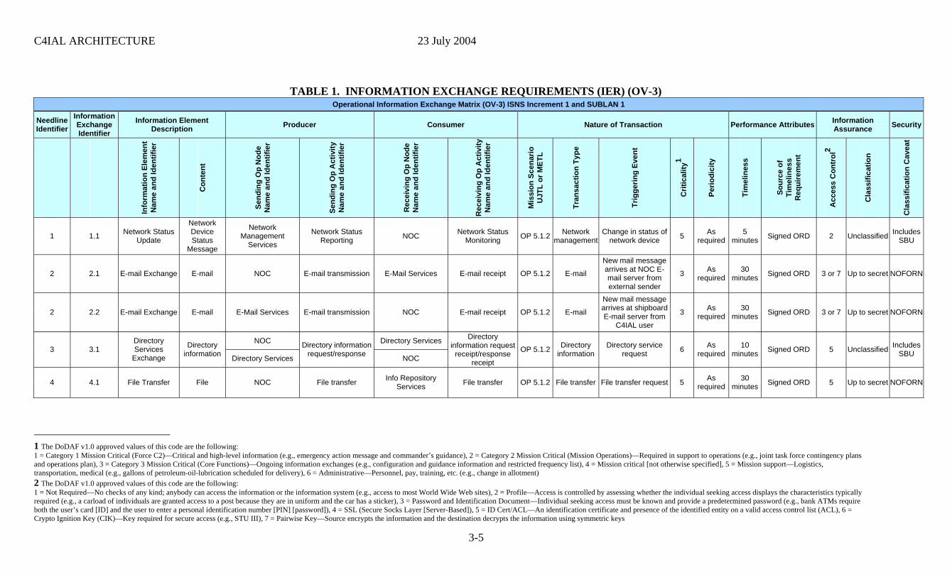
Table 1 below lists the information exchange requirements for C4IAL. The entries on the table are based on the 13 need lines of the OV-2 (Figure 2). The IERs are traced to the two tasks of the C4IAL from the Universal Joint Task List (UJTL), OP 5.1.2 Manage Means of Communicating Operational Information and OP 6.3.4 Protect Information Systems in the Joint Operations Area.
3-4
C4IAL ARCHITECTURE 23 July 2004
TABLE 1. INFORMATION EXCHANGE REQUIREMENTS (IER) (OV-3) Operational Information Exchange Matrix (OV-3) ISNS Increment 1 and SUBLAN 1
Needline Identifier
Information Exchange Identifier
Information Element Description Producer Consumer Nature of Transaction Performance Attributes Information
Assurance Security
Info
rmat
ion
Elem
ent
Nam
e an
d Id
entif
ier
Con
tent
Send
ing
Op
Nod
e N
ame
and
Iden
tifie
r
Send
ing
Op
Act
ivity
N
ame
and
Iden
tifie
r
Rec
eivi
ngp
Nod
e O
Ne
and
Iden
tifie
r am
Rec
eivi
ngp
Act
ivity
O
Ne
and
Iden
tifie
r am M
issi
on S
cena
rio
UJT
L or
MET
L
Tran
sact
ion
Type
Trig
gerin
g Ev
ent
Crit
ical
ity1
Perio
dici
ty
Tim
elin
ess
Sf
ourc
e o
Tim
elin
ess
Rire
men
t eq
u
Acc
ess
Con
trol
2
Cla
ssifi
catio
n
Cla
ssifi
catio
n C
avea
t
1 1.1 Network Status
Update
Network Device Status
Message
Network Management
Services
Network Status Reporting NOC Network Status
Monitoring OP 5.1.2 Network management
Change in status of network device 5 As
required 5
minutes Signed ORD 2 Unclassified Includes SBU
2 2.1 E-mail Exchange E-mail NOC E-mail transmission E-Mail Services E-mail receipt OP 5.1.2 E-mail
New mail message arrives at NOC E-mail server from external sender
3 As required
30 minutes Signed ORD 3 or 7 Up to secret NOFORN
2 2.2 E-mail Exchange E-mail E-Mail Services E-mail transmission NOC E-mail receipt OP 5.1.2 E-mail
New mail message arrives at shipboard E-mail server from
C4IAL user
3 As required
30 minutes Signed ORD 3 or 7 Up to secret NOFORN
NOC Directory Services
3 3.1Directory Services
Exchange
Directory information Directory Services
Directory information request/response NOC
Directory information request
receipt/response receipt
OP 5.1.2 Directory information
Directory service request 6 As
required 10
minutes Signed ORD 5 Unclassified Includes SBU
4 4.1 File Transfer File NOC File transfer Info Repository
Services File transfer OP 5.1.2 File transfer File transfer request 5 As required
30 minutes Signed ORD 5 Up to secret NOFORN
1 The DoDAF v1.0 approved values of this code are the following: 1 = Category 1 Mission Critical (Force C2)—Critical and high-level information (e.g., emergency action message and commander’s guidance), 2 = Category 2 Mission Critical (Mission Operations)—Required in support to operations (e.g., joint task force contingency plans and operations plan), 3 = Category 3 Mission Critical (Core Functions)—Ongoing information exchanges (e.g., configuration and guidance information and restricted frequency list), 4 = Mission critical [not otherwise specified], 5 = Mission support—Logistics, transportation, medical (e.g., gallons of petroleum-oil-lubrication scheduled for delivery), 6 = Administrative—Personnel, pay, training, etc. (e.g., change in allotment) 2 The DoDAF v1.0 approved values of this code are the following: 1 = Not Required—No checks of any kind; anybody can access the information or the information system (e.g., access to most World Wide Web sites), 2 = Profile—Access is controlled by assessing whether the individual seeking access displays the characteristics typically required (e.g., a carload of individuals are granted access to a post because they are in uniform and the car has a sticker), 3 = Password and Identification Document—Individual seeking access must be known and provide a predetermined password (e.g., bank ATMs require both the user’s card [ID] and the user to enter a personal identification number [PIN] [password]), 4 = SSL (Secure Socks Layer [Server-Based]), 5 = ID Cert/ACL—An identification certificate and presence of the identified entity on a valid access control list (ACL), 6 = Crypto Ignition Key (CIK)—Key required for secure access (e.g., STU III), 7 = Pairwise Key—Source encrypts the information and the destination decrypts the information using symmetric keys
3-5
C4IAL ARCHITECTURE 23 July 2004
Operational Information Exchange Matrix (OV-3) ISNS Increment 1 and SUBLAN 1
Needline Identifier
Information Exchange Identifier
Information Element Description Producer Consumer Nature of Transaction Performance Attributes Information
Assurance Security
Info
rmat
ion
Elem
ent
Nam
e an
d Id
entif
ier
Con
tent
Send
ing
Op
Nod
e N
ame
and
Iden
tifie
r
Send
ing
Op
Act
ivity
N
ame
and
Iden
tifie
r
Rec
eivi
ngp
Nod
e O
Ne
and
Iden
tifie
r am
Rec
eivi
ngp
Act
ivity
O
Ne
and
Iden
tifie
r am M
issi
on S
cena
rio
UJT
L or
MET
L
Tran
sact
ion
Type
Trig
gerin
g Ev
ent
Crit
ical
ity1
Perio
dici
ty
Tim
elin
ess
Sf
ourc
e o
Tim
elin
ess
Rire
men
t eq
u
Acc
ess
Con
trol
2
Cla
ssifi
catio
n
Cla
ssifi
catio
n C
avea
t
4 4.2 File Transfer File Info Repository
Services File transfer NOC File transfer OP 5.1.2 File transfer File transfer request 5 As required
30 minutes Signed ORD 5 Up to secret NOFORN
5 5.1 Web Information Exchange Web page NOC Web information
transmission Web Services Web information receipt OP 5.1.2 Web
informationWeb information
request 5 As required
30 minutes Signed ORD 3, 4, or
7 Up to secret NOFORN
6 6.1 Network Status Update
Network Device Status
Message
Network Management
Services
Network Status Reporting C4IAL user Network Status
Monitoring OP 5.1.2 Network management
Change in status of network device 5 As
required 1 second Engineering assessment 3 Unclassified Includes
SBU
C4IAL user Network
Management Services
6 6.2
Network Device Configuration
Data
Network Device
Configuration Data
Network Management
Services
Network Device Configuration Data request/response C4IAL user
Network Device Configuration Data
request receipt/response
receipt
OP 5.1.2 Network management
Network device configuration data
request 5 As
required 3
seconds Engineering assessment 3 or 7 Unclassified Includes
SBU
6 6.3
Network Device Configuration
Data
Network Device
Configuration Data
C4IAL user Network Device Configuration Change
Network Management
Services
Network Device Configuration
Change receipt
OP 5.1.2, OP 6.3.4
Network management
Network device configuration change
request 5 As
required 1 second Engineering assessment 3 or 7 Unclassified Includes
SBU
7 7.1 E-mail Exchange E-mail E-Mail Services E-mail transmission C4IAL user E-mail receipt OP 5.1.2 E-mail
New mail message arrives at shipboard
E-mail server for C4IAL user
3 As required
2 seconds
Engineering assessment 3 or 7 Up to secret NOFORN
7 7.2 E-mail Exchange E-mail C4IAL user E-mail transmission E-Mail Services E-mail receipt OP 5.1.2 E-mail New mail message sent by C4IAL user 3 As
required 2
seconds Engineering assessment 3 or 7 Up to secret NOFORN
C4IAL user Directory Services
8 8.1Directory Services
Exchange
Directory information Directory Services
Directory information request/response C4IAL user
Directory information request
receipt/response receipt
OP 5.1.2 Directory information
Directory service request 6 As
required 5
seconds Engineering assessment 5 Unclassified Includes
SBU
9 9.1 File Transfer File C4IAL user File transfer Info Repository Services File transfer OP 5.1.2 File transfer File transfer request 5 As
required 20
seconds Engineering assessment 5 Up to secret NOFORN
3-6

C4IAL ARCHITECTURE 23 July 2004
Operational Information Exchange Matrix (OV-3) ISNS Increment 1 and SUBLAN 1
Needline Identifier
Information Exchange Identifier
Information Element Description Producer Consumer Nature of Transaction Performance Attributes Information
Assurance Security
Info
rmat
ion
Elem
ent
Nam
e an
d Id
entif
ier
Con
tent
Send
ing
Op
Nod
e N
ame
and
Iden
tifie
r
Send
ing
Op
Act
ivity
N
ame
and
Iden
tifie
r
Rec
eivi
ngp
Nod
e O
Ne
and
Iden
tifie
r am
Rec
eivi
ngp
Act
ivity
O
Ne
and
Iden
tifie
r am M
issi
on S
cena
rio
UJT
L or
MET
L
Tran
sact
ion
Type
Trig
gerin
g Ev
ent
Crit
ical
ity1
Perio
dici
ty
Tim
elin
ess
Sf
ourc
e o
Tim
elin
ess
Rire
men
t eq
u
Acc
ess
Con
trol
2
Cla
ssifi
catio
n
Cla
ssifi
catio
n C
avea
t
C4IAL user Web Services 10 10.1 Web Information
Exchange Web page Web Services
Web information request/response C4IAL user
Web information request
receipt/response receipt
OP 5.1.2 Web information
Web information request 5 As
required 5
seconds Engineering assessment
3, 4, or 7 Up to secret NOFORN
11 11.1 User Account Setup
Account information
and permissions
C4IAL user User account creation/modification
Account Management/Security
Services
User account creation/modification
OP 5.1.2, OP 6.3.4
Network access
User account creation/modification
request 6 As
required 2
minutes Engineering assessment 5 Up to secret NOFORN
C4IAL user Account
Management/Security Services
11 11.2 User Login
Account information
and permissions
Account Management/Security
Services
Network access request/response
C4IAL user
Network access request
receipt/response receipt
OP 5.1.2, OP 6.3.4
Network access
Network access request 5 As
required 10
seconds Engineering assessment 3 or 7 Up to secret NOFORN
12 12.1 Office Automation File data C4IAL user
Data access, change, save
request/response
Office Automation Services
Data access, change, save
request receipt/response
receipt
OP 5.1.2,OP 6.3.4
Office automation
Data access, change, save
request 3 As
required 5
seconds Engineering assessment 2 Up to secret NOFORN
13 13.1 Print job Print file C4IAL user Print job request Print Services Print job processing OP 5.1.2 Printing Print job request 6 As
required 30
seconds Engineering assessment 2 Up to secret NOFORN
3-7
C4IAL ARCHITECTURE 23 July 2004
This page intentionally left blank.
3-8
C4IAL ARCHITECTURE 23 July 2004
3.4.4 Organizational Relationships Chart (OV-4)
An Organizational Relationships Chart (OV-4) is not meaningful for the C4IAL architecture, due to the fact that C4IAL is an infrastructure system. Therefore, an OV-4 is not provided as part of this architecture.
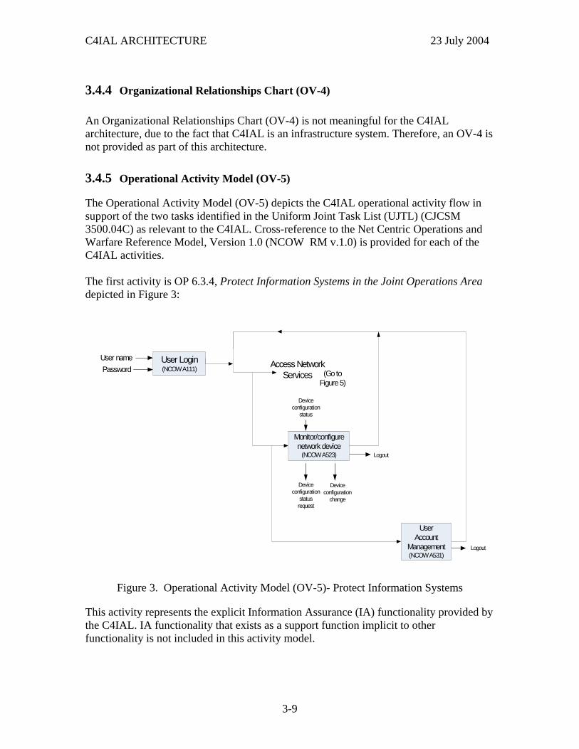
3.4.5 Operational Activity Model (OV-5)
The Operational Activity Model (OV-5) depicts the C4IAL operational activity flow in support of the two tasks identified in the Uniform Joint Task List (UJTL) (CJCSM 3500.04C) as relevant to the C4IAL. Cross-reference to the Net Centric Operations and Warfare Reference Model, Version 1.0 (NCOW RM v.1.0) is provided for each of the C4IAL activities. The first activity is OP 6.3.4, Protect Information Systems in the Joint Operations Area depicted in Figure 3:
User name User Login(NCOW A111)Password Access Network
Services
Monitor/configure network device
(NCOW A523) Logout
Logout
UserAccount
Management(NCOW A531)
Device configuration
status request
Device configuration
status
Device configuration
change
(Go to Figure 5)
Figure 3. Operational Activity Model (OV-5)- Protect Information Systems
This activity represents the explicit Information Assurance (IA) functionality provided by the C4IAL. IA functionality that exists as a support function implicit to other functionality is not included in this activity model.
3-9
C4IAL ARCHITECTURE 23 July 2004
The operational process of protecting information systems begins with the authenticatioof the C4IAL user. Unauthorized users, lacking user names and passwords, will be prohibited from logging in and accessing the network. The authorized user may be the C4IAL system administrator user or common user. All users will have permissions on various levels to access network services. Only the C4IAL system administrator usbe authoriz
n
er will ed to access account management services in order to create, modify or delete
user accounts and to monitor and configure security devices and software for data
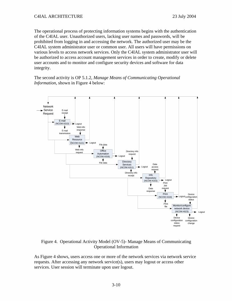
The second activity is OP 5.1.2, Manage Means of Communicating Operational nformation, shown in Figure 4 below:
integrity.
I
E-mailreceipt
E-mailtransmssion
PrintJob
request
Dataaccessrequest
NetworkServiceRequest
Data response
Directory inforequest
Logout
Web Resource
(NCOW A121)
OfficeAutomation
(NCOW A316)
Directory Services
(NCOW A311)
Info Repository
(NCOW A315)
Print(NCOW A316)
Monitor/configure network device(NCOW A523)
E-mail(NCOW A313)
Logout
Logout
Logout
Logout
Logout
Directory inforeceipt
Web inforesponse
Device configuration
status
Device configuration
change
Logout
Printfile
Web info request
Device configuration
status request
File data
File data
Figure 4. Operational Activity Model (OV-5)- Manage Means of Communicating
ork services via network service requests. After accessing any network service(s), users may logout or access other services. User session will terminate upon user logout.
Operational Information
As Figure 4 shows, users access one or more of the netw
3-10
C4IAL ARCHITECTURE 23 July 2004
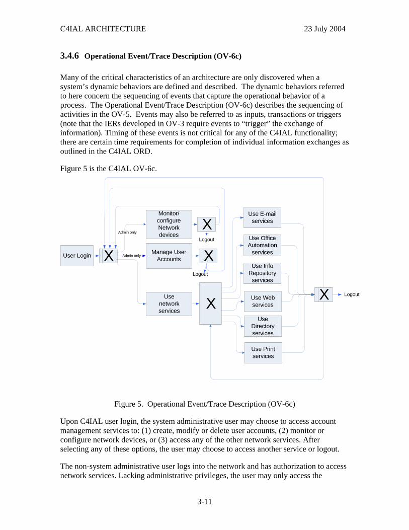
3.4.6 Operational Event/Trace Description (OV-6c)
Many of the critical characteristics of an architecture are only discovered when a system’s dynamic behaviors are defined and described. The dynamic behaviors referred to here concern the sequencing of events that capture the operational behavior of a process. The Operational Event/Trace Description (OV-6c) describes the sequencing of activities in the OV-5. Events may also be referred to as inputs, transactions or triggers (note that the IERs developed in OV-3 require events to “trigger” the exchange of information). Timing of these events is not critical for any of the C4IAL functionality; there are certain time requirements for completion of individual information exchanges as outlined in the C4IAL ORD.
Figure 5 is the C4IAL OV-6c.
Admin onlyUser Login
Usenetworkservices
Manage User Accounts
Monitor/configureNetworkdevices
Use E-mailservices
Use OfficeAutomation
services
Use InfoRepositoryservices
Use Webservices
Use Printservices
Use Directoryservices
Logout
Logout
Logout
X
XX
X
XAdmin only
Figure 5. Operational Event/Trace Description (OV-6c)
Upon C4IAL user login, the system administrative user may choose to access account management services to: (1) create, modify or delete user accounts, (2) monitor or configure network devices, or (3) access any of the other network services. After selecting any of these options, the user may choose to access another service or logout.
The non-system administrative user logs into the network and has authorization to access network services. Lacking administrative privileges, the user may only access the
3-11
C4IAL ARCHITECTURE 23 July 2004
network services. The user may return to access other services as often as desired until the decision is made to logout. All services terminate for the user upon logout.
3-12
C4IAL ARCHITECTURE 23 July 2004
4 SYSTEMS VIEW (SV)
4.1 Introduction
The Systems View (SV) describes “how” the process and information capabilities identified in the OV are to be implemented. The SV also identifies and depicts the DoD system requirements for elements such as security, interoperability, and reach-back.
4.2 Scope
The various System Views (SV) show how multiple systems are linked and integrated based upon the capabilities and operation of particular systems within the architecture. The associated products developed with the SV are:
• SV-1: The System Interface Description identifies systems and their interfaces within and between nodes
• SV-2: The Systems Communications Description depicts system nodes, systems, and system items, and their related communications lay downs.
• SV-4: The Systems Functionality Description describes functions performed by systems and the information flow among system functions
• SV-5: The Operational Activity to Systems Functions Traceability Matrix maps system functions back to operational activities
• SV-6: The Systems Data Exchange Matrix details information exchanges among system functions.
The SV-3 Systems-Systems matrix is not a required architecture product.
This section provides an overview of the SV, outlines the methodology employed in developing the SV and presents the high level SV products.
4.3 C4IAL SV Development Process
The System Views (SV) development process is similar to the process used in developing the OV. The functionality of those systems needed to support the respective operational requirements was identified through the following process:
• System functionality was identified
4-1
C4IAL ARCHITECTURE 23 July 2004
• Migration paths and strategies were identified
• Applicable systems were mapped to system functions
• System functions were mapped back to the operational activities
• System information flow and exchange among operational nodes were identified
Development of the SV is ongoing and new data will be integrated into the resulting SV products.
4.4 SV Products
The following Systems View architecture products were produced:
• SV-1: Systems Interface Description
• SV-2: Systems Communication Description
• SV-4: Systems Functionality Description
• SV-5: Operational Activity to Systems Function Traceability Matrix
• SV-6: Systems Data Exchange Matrix
A Systems-Systems Matrix (SV-3) was not required nor prepared for this architecture.
4.4.1 Systems Interface Description (SV-1)
The Systems Interface Description (SV-1) links together the Operational and Systems Views by depicting the assignments of systems and their interfaces to the nodes and need lines described in the OV-2. The OV-2 shows Operational Nodes while the Systems Interface Description depicts the corresponding systems nodes.
The Systems View is an extension of the Operational View. From an operational perspective, each of these IERs represents which nodes need to communicate (From – To nodes), what activity or task is being performed at the sending node, and what information is being sent (IE Name). From an SV perspective, the same need line represents different information. From this viewpoint, the “From node” need line represents an IE Name, the systems required to generate the information, and the systems required to transmit the information. Likewise, a “To node” need line represents the systems necessary to receive, process, and disseminate the informational internally within the node.
4-2
C4IAL ARCHITECTURE 23 July 2004
Services Internalto the System
E-Mail*Web Browsing*NetworkManagement*AccountManagementDirectory Services*Print ServicesFile Transfer*File CompressionOffice AutomationSecurity
C4I LAN
- Switch
- Workstation
- Server
- Peripheral Drop
ADNS
ADNS
Note: Services shown areaccessible internally fromthe C4I LAN. Servicesindicated with a * occurexternal to the C4I LAN aswell.
ALLIED
DISN
PSN
NOC
Shore
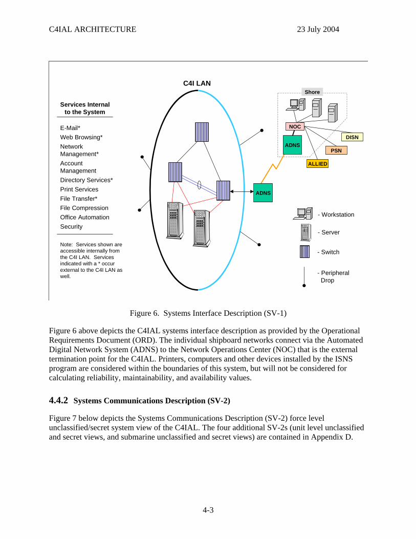
Figure 6. Systems Interface Description (SV-1)
Figure 6 above depicts the C4IAL systems interface description as provided by the Operational Requirements Document (ORD). The individual shipboard networks connect via the Automated Digital Network System (ADNS) to the Network Operations Center (NOC) that is the external termination point for the C4IAL. Printers, computers and other devices installed by the ISNS program are considered within the boundaries of this system, but will not be considered for calculating reliability, maintainability, and availability values.
4.4.2 Systems Communications Description (SV-2)
Figure 7 below depicts the Systems Communications Description (SV-2) force level unclassified/secret system view of the C4IAL. The four additional SV-2s (unit level unclassified and secret views, and submarine unclassified and secret views) are contained in Appendix D.
4-3
C4IAL ARCHITECTURE 23 July 2004
SV-2
SERVER
WORKSTATIONSERVER
PRINTER NOTES: 1) ANY CONNECTION FOUND ON EDGE SWITCH 1 MAY BE FOUND ON ANY EDGE SWITCH N.2) LINES DO NOT REPRESENT PHYSICAL CONNECTIONS, ONLY LOGICAL COMMUNICATION PATHS. 3) NON C4IAL CONNECTIONS MADE TO THE BACKBONE SWITCHES MAYBE SINGLE HOMED.
EIA/TIA 530A UNCLASS ONLY
IEEE 802.3
C4IAL NON-C4IAL
EDGE SWITCH NEDGE SWITCH 1
BACKBONE SWITCH 2BACKBONE SWITCH 1
ROUTERSERVER
PRINTER
WORKSTATION
Note 3
Note 1
LAN
WIDE AREA NETWORK TRANSPORT
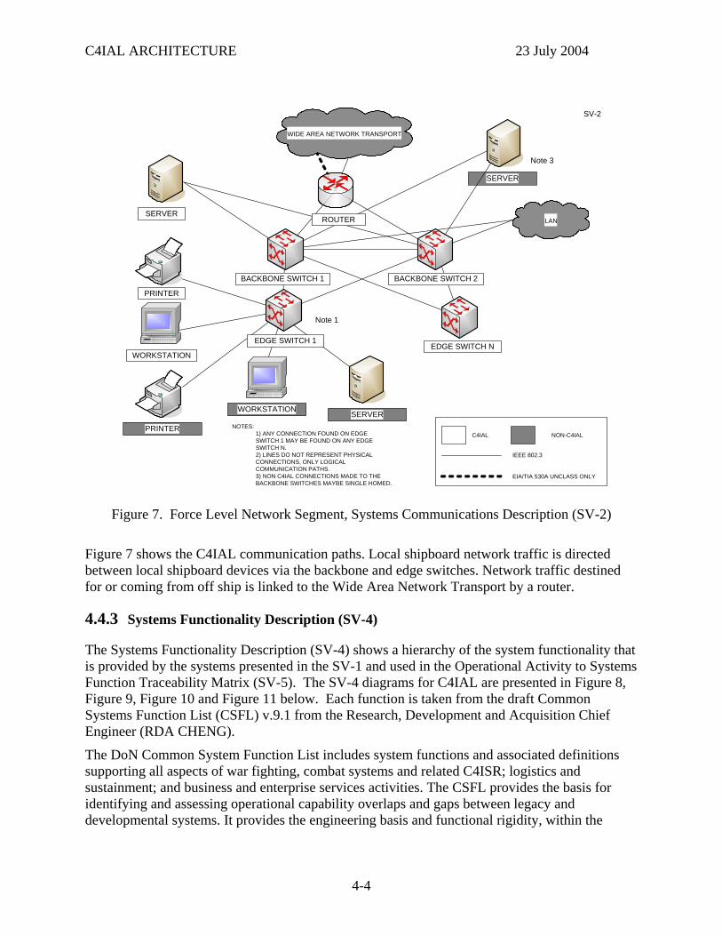
Figure 7. Force Level Network Segment, Systems Communications Description (SV-2)
Figure 7 shows the C4IAL communication paths. Local shipboard network traffic is directed between local shipboard devices via the backbone and edge switches. Network traffic destined for or coming from off ship is linked to the Wide Area Network Transport by a router.
4.4.3 Systems Functionality Description (SV-4)
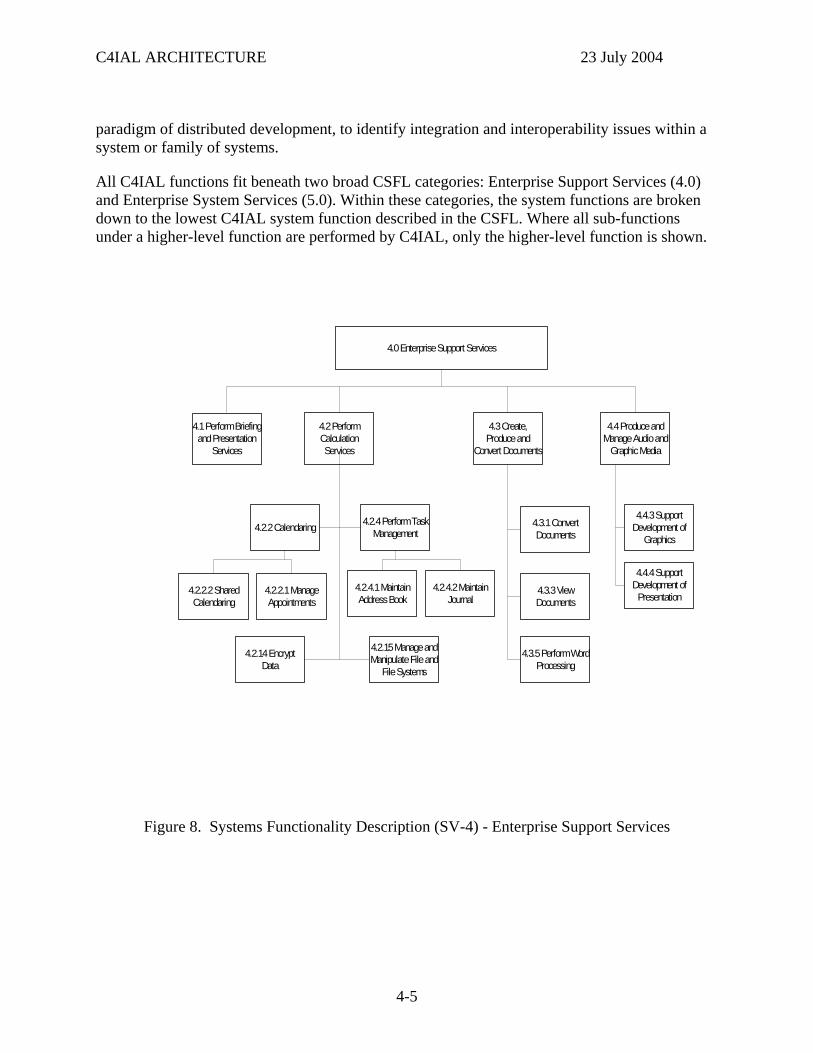
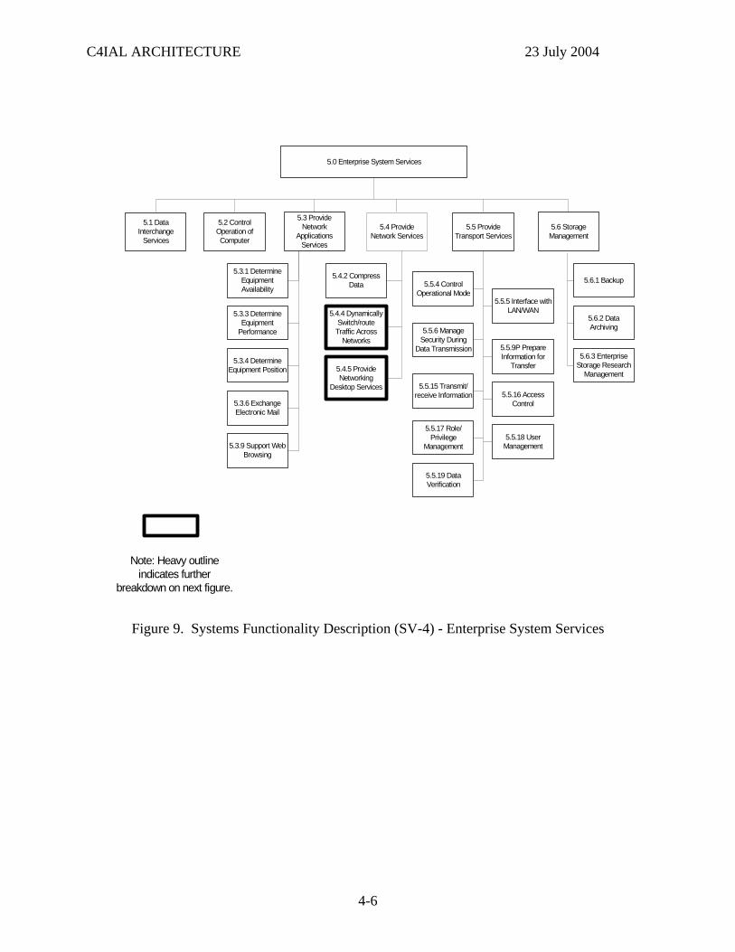
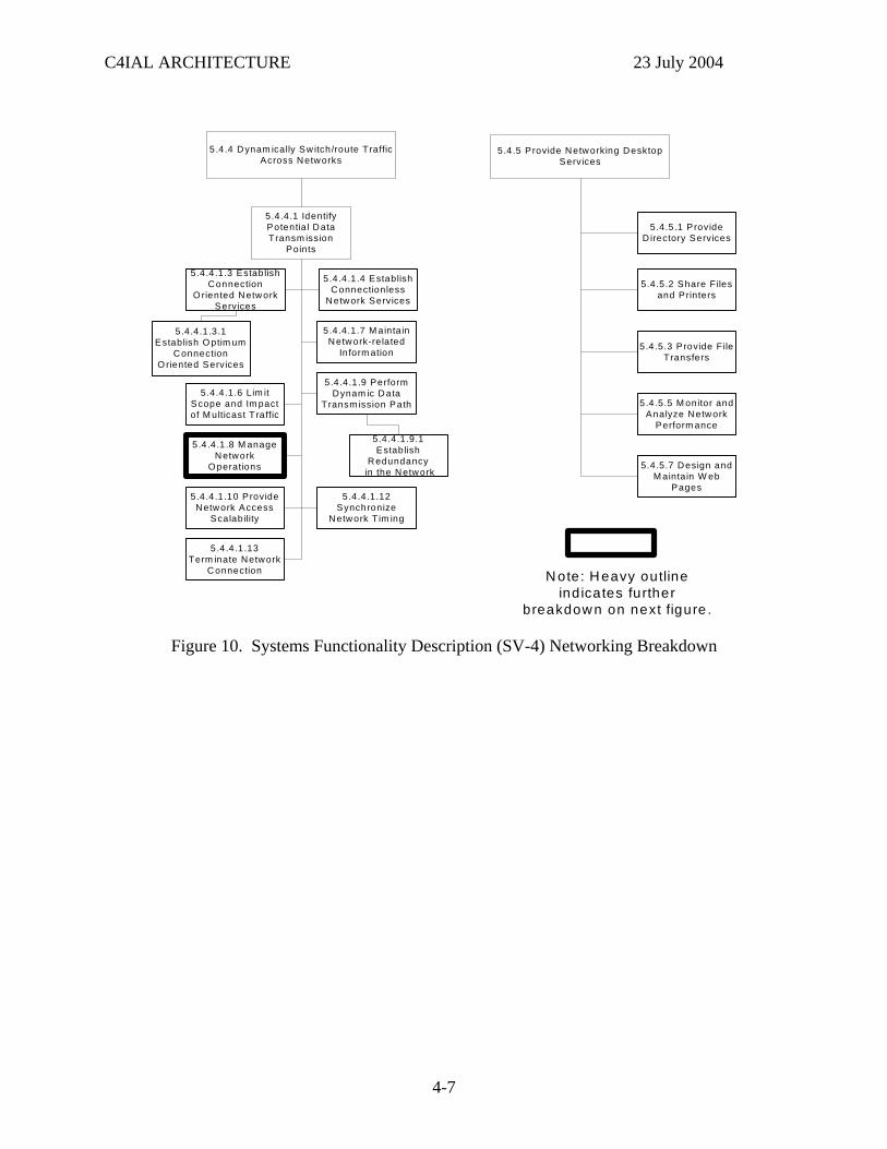
The Systems Functionality Description (SV-4) shows a hierarchy of the system functionality that is provided by the systems presented in the SV-1 and used in the Operational Activity to Systems Function Traceability Matrix (SV-5). The SV-4 diagrams for C4IAL are presented in Figure 8, Figure 9, Figure 10 and Figure 11 below. Each function is taken from the draft Common Systems Function List (CSFL) v.9.1 from the Research, Development and Acquisition Chief Engineer (RDA CHENG).
The DoN Common System Function List includes system functions and associated definitions supporting all aspects of war fighting, combat systems and related C4ISR; logistics and sustainment; and business and enterprise services activities. The CSFL provides the basis for identifying and assessing operational capability overlaps and gaps between legacy and developmental systems. It provides the engineering basis and functional rigidity, within the
4-4
C4IAL ARCHITECTURE 23 July 2004
paradigm of distributed development, to identify integration and interoperability issues within a system or family of systems.
All C4IAL functions fit beneath two broad CSFL categories: Enterprise Support Services (4.0) and Enterprise System Services (5.0). Within these categories, the system functions are broken down to the lowest C4IAL system function described in the CSFL. Where all sub-functions under a higher-level function are performed by C4IAL, only the higher-level function is shown.
4.1 Perform Briefing and Presentation
Services
4.2 Perform Calculation Services
4.0 Enterprise Support Services
4.2.2 Calendaring
4.3 Create, Produce and
Convert Documents
4.4 Produce and Manage Audio and
Graphic Media
4.3.3 View Documents
4.3.1 Convert Documents
4.4.3 Support Development of
Graphics
4.4.4 Support Development of Presentation
4.2.4 Perform Task Management
4.2.14 EncryptData
4.2.15 Manage and Manipulate File and
File Systems
4.2.4.1 Maintain Address Book
4.2.4.2 Maintain Journal
4.2.2.1 Manage Appointments
4.2.2.2 Shared Calendaring
4.3.5 Perform Word Processing
Figure 8. Systems Functionality Description (SV-4) - Enterprise Support Services
4-5
C4IAL ARCHITECTURE 23 July 2004
5.1 Data Interchange
Services
5.2 Control Operation of Computer
5.0 Enterprise System Services
5.5.5 Interface with LAN/WAN
5.4 Provide Network Services
5.5 Provide Transport Services
5.4.4 Dynamically Switch/route Traffic Across
Networks
5.4.2 Compress Data
5.3.1 Determine Equipment Availability
5.6 Storage Management
5.3.6 Exchange Electronic Mail
5.3.3 Determine Equipment
Performance
5.3.4 Determine Equipment Position
5.3.9 Support Web Browsing
5.5.4 Control Operational Mode
5.5.6 Manage Security During
Data Transmission
5.4.5 Provide Networking
Desktop Services
5.6.1 Backup
5.5.19 Data Verification
5.5.18 User Management
5.5.17 Role/Privilege
Management
5.5.15 Transmit/receive Information
5.5.9P Prepare Information for
Transfer
5.5.16 Access Control
5.3 Provide Network
Applications Services
5.6.2 Data Archiving
5.6.3 Enterprise Storage Research
Management
Note: Heavy outline indicates further
breakdown on next figure.
Figure 9. Systems Functionality Description (SV-4) - Enterprise System Services
4-6
C4IAL ARCHITECTURE 23 July 2004
5.4.5.3 Provide File Transfers
5.4 .4 Dynam ically Sw itch/route Traffic Across Networks
5.4.5 Provide Networking Desktop Services
5.4.4.1.12 Synchronize
Network T im ing
5.4.4.1.7 M ainta in Network-re lated
Inform ation
5.4.4.1.10 Provide Network Access
Scalability
5 .4 .4 .1 .8 M anage Network
O perations
5.4.4.1 Identify Potentia l Data Transm ission
Points
5.4.5.7 Design and M ainta in W eb
Pages
5.4.4 .1 .13 Term inate Network
Connection
5.4.4.1.9 Perform Dynam ic Data
Transm ission Path
5.4 .4 .1 .3 Establish Connection
O riented Network Services
5.4.4.1.6 L im it Scope and Im pact of M ulticast Traffic
5 .4.4 .1 .4 Establish Connectionless
Network Services
5.4.5.1 Provide D irectory Services
5.4.5.2 Share F iles and Printers
5.4.5.5 M onitor and Analyze Network
Perform ance
5.4.4.1.3.1 Establish O ptim um
Connection O riented Services
5.4.4.1.9.1 Establish
Redundancy in the Network
N ote: H eavy outline indicates further
breakdow n on next figure .
Figure 10. Systems Functionality Description (SV-4) Networking Breakdown
4-7
C4IAL ARCHITECTURE 23 July 2004
5.4.4.1.8.4 Perform Automated Fault
Management
5.4.4.1.8 Manage Network Operations
5.4.4.1.8.3 Perform Account
Management
5.4.4.1.8.1 Automatically Generate and
Display Network Status
5.4.4.1.8.2 Conduct Performance Management
5.4.4.1.8.7 Perform Network
IA/Security Management
5.4.4.1.8.8 Perform Technical Control of
Network
5.4.4.1.8.5 Perform Dynamic
Configuration Management
5.4.4.1.8.9 Provide Network Manager Human Systems
Integration
5.4.4.1.8.7.2 Ensure Data Information
Confidentiality 5.4.4.1.8.7.2.2 Encrypt
Information/data
5.4.4.1.8.7.1 Authenticate User
Access 5.4.4.1.8.7.2.1 Decrypt
Information/data
5.4.4.1.8.5.4 Manually Configure/
reconfigure the Network
5.4.4.1.8.7.2.2.2 Perform Content based Encryption
5.4.4.1.8.7.3 Ensure
Nonrepudiation
5.4.4.1.8.7.4 Maintain Data File
Integrity
5.4.4.1.8.7.5 Prevent Opportunity
to Attack
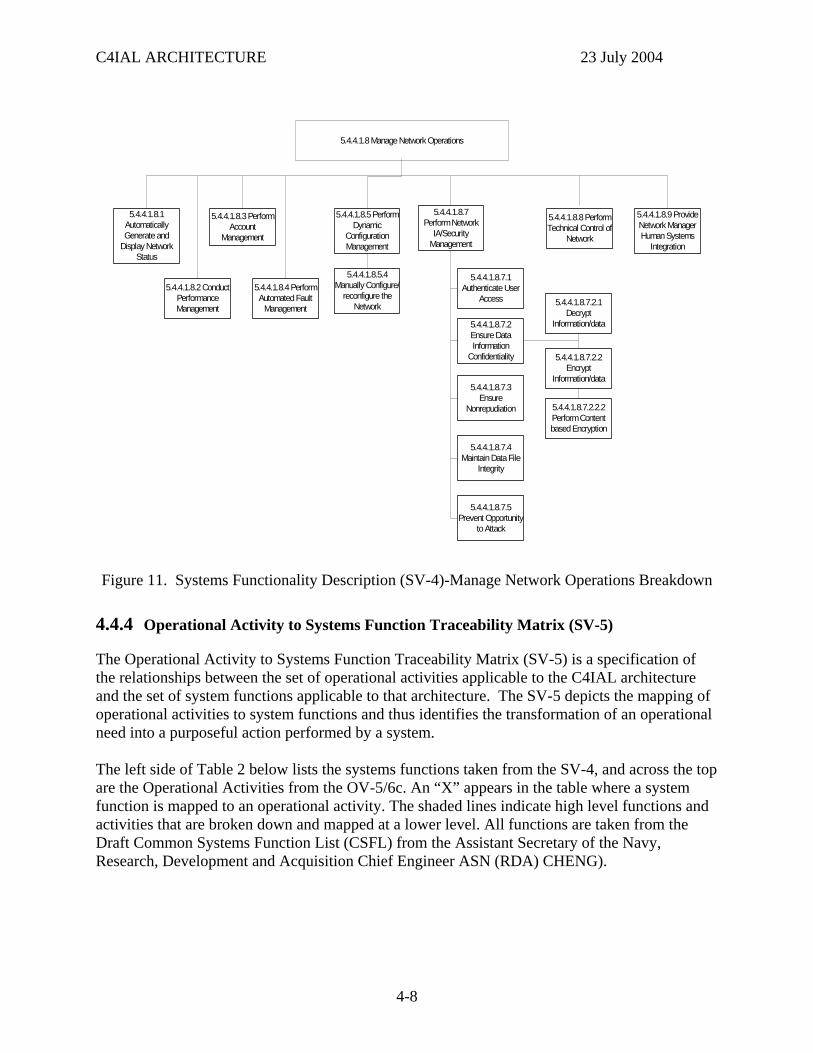
Figure 11. Systems Functionality Description (SV-4)-Manage Network Operations Breakdown
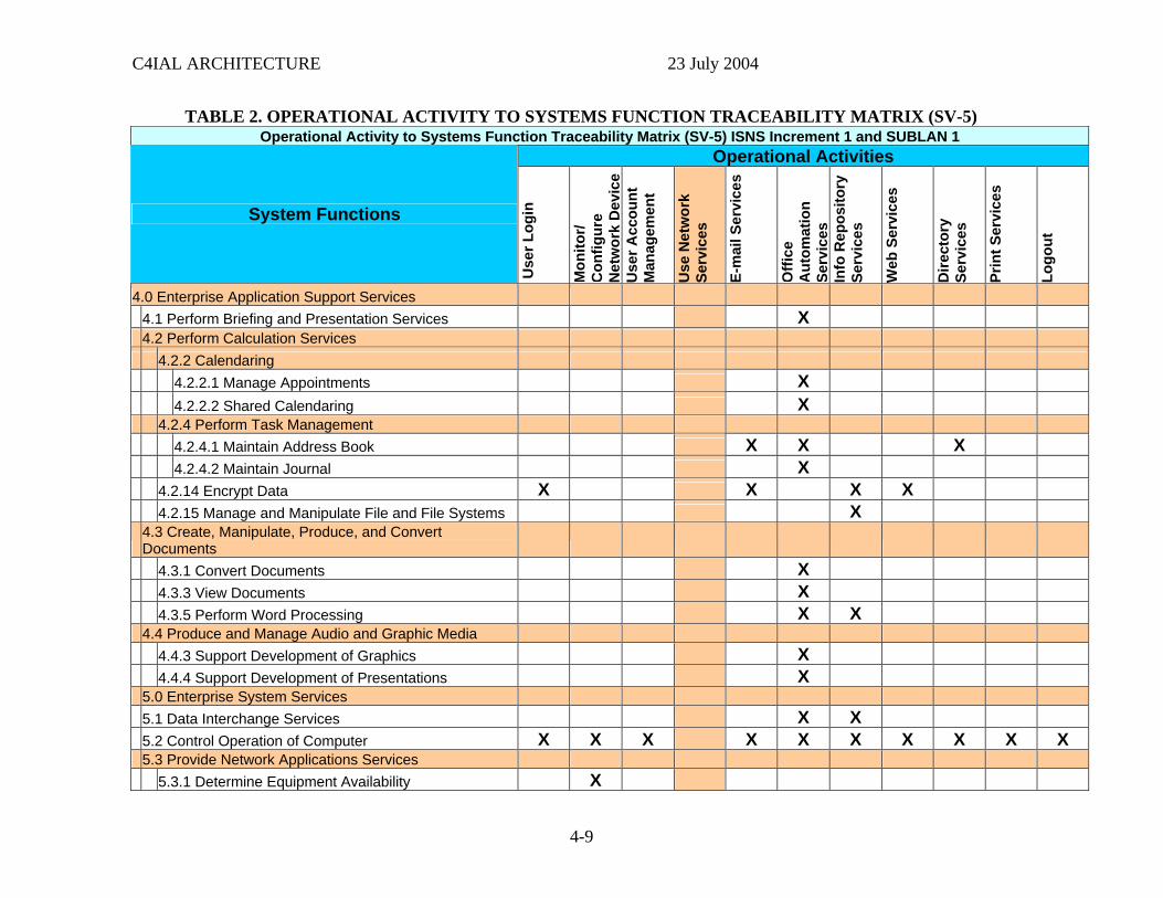
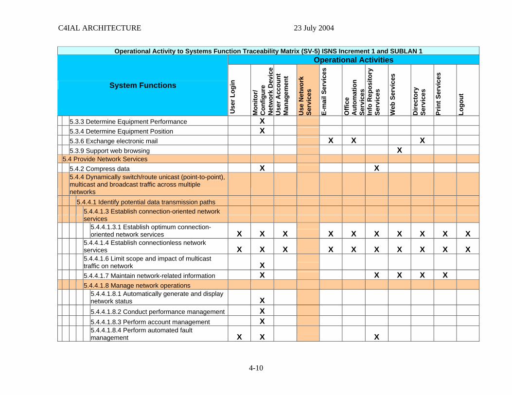
4.4.4 Operational Activity to Systems Function Traceability Matrix (SV-5)
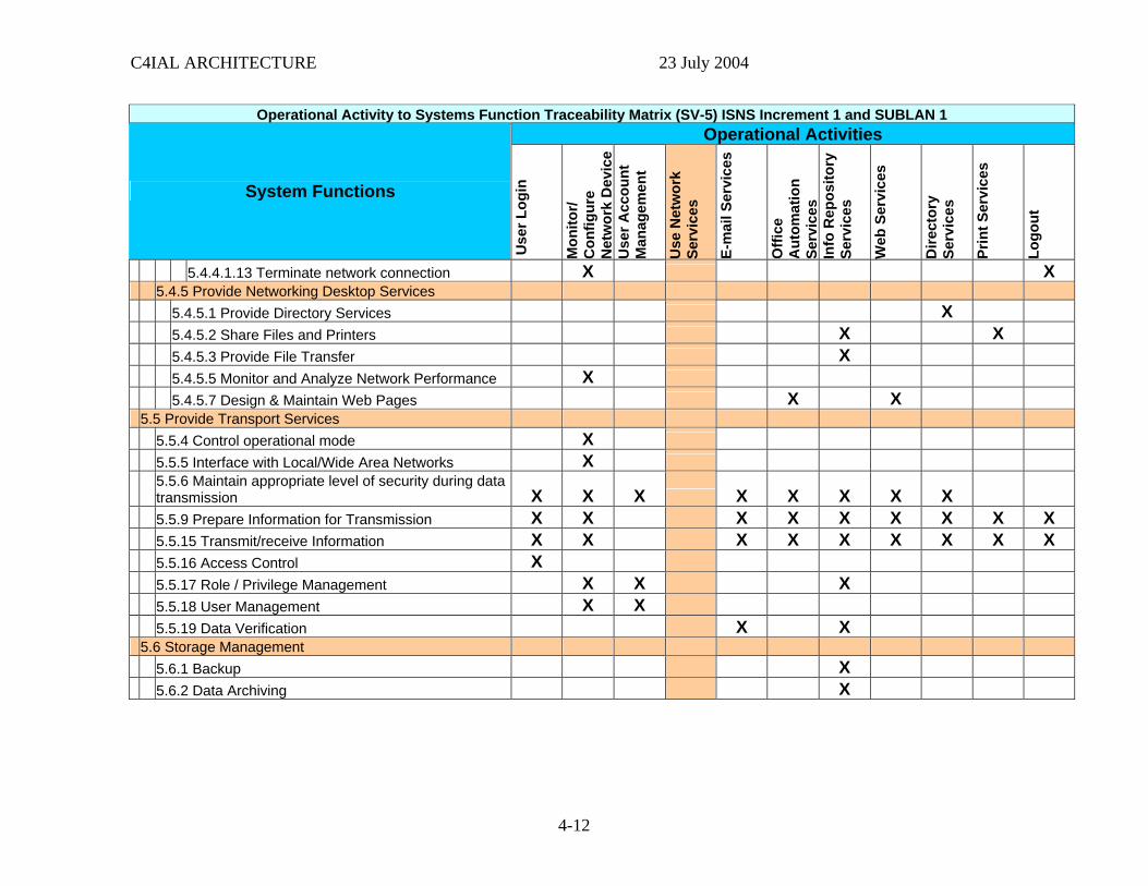
The Operational Activity to Systems Function Traceability Matrix (SV-5) is a specification of the relationships between the set of operational activities applicable to the C4IAL architecture and the set of system functions applicable to that architecture. The SV-5 depicts the mapping of operational activities to system functions and thus identifies the transformation of an operational need into a purposeful action performed by a system. The left side of Table 2 below lists the systems functions taken from the SV-4, and across the top are the Operational Activities from the OV-5/6c. An “X” appears in the table where a system function is mapped to an operational activity. The shaded lines indicate high level functions and activities that are broken down and mapped at a lower level. All functions are taken from the Draft Common Systems Function List (CSFL) from the Assistant Secretary of the Navy, Research, Development and Acquisition Chief Engineer ASN (RDA) CHENG).
4-8
C4IAL ARCHITECTURE 23 July 2004
TABLE 2. OPERATIONAL ACTIVITY TO SYSTEMS FUNCTION TRACEABILITY MATRIX (SV-5) Operational Activity to Systems Function Traceability Matrix (SV-5) ISNS Increment 1 and SUBLAN 1
Operational Activities
System Functions
Use
r Log
in
Mon
itor/
Con
figur
e N
etw
ork
Dev
ice
Uco
unt
Man
agem
ser A
cen
t
Use
Net
wor
k Se
rvic
es
E-m
ail S
ervi
ces
Offi
ce
Aut
omat
ion
Se
rvic
es
Info
Rep
osito
ry
Serv
ices
Web
Ser
vice
s
Dire
ctor
y Se
rvic
es
Prin
t Ser
vice
s
Logo
ut
4.0 Enterprise Application Support Services 4.1 Perform Briefing and Presentation Services X 4.2 Perform Calculation Services 4.2.2 Calendaring 4.2.2.1 Manage Appointments X 4.2.2.2 Shared Calendaring X 4.2.4 Perform Task Management 4.2.4.1 Maintain Address Book X X X 4.2.4.2 Maintain Journal X 4.2.14 Encrypt Data X X X X 4.2.15 Manage and Manipulate File and File Systems X
4.3 Create, Manipulate, Produce, and Convert Documents
4.3.1 Convert Documents X 4.3.3 View Documents X 4.3.5 Perform Word Processing X X 4.4 Produce and Manage Audio and Graphic Media 4.4.3 Support Development of Graphics X 4.4.4 Support Development of Presentations X 5.0 Enterprise System Services 5.1 Data Interchange Services X X 5.2 Control Operation of Computer X X X X X X X X X X 5.3 Provide Network Applications Services 5.3.1 Determine Equipment Availability X
4-9
C4IAL ARCHITECTURE 23 July 2004
Operational Activity to Systems Function Traceability Matrix (SV-5) ISNS Increment 1 and SUBLAN 1 Operational Activities
System Functions
Use
r Log
in
Mon
itor/
Con
figur
e N
etw
ork
Dev
ice
Uco
unt
Man
agem
ent
ser A
c
Use
Net
wor
k Se
rvic
es
E-m
ail S
ervi
ces
Offi
ce
Aut
omat
ion
Se
rvic
es
Info
Rep
osito
ry
Serv
ices
Web
Ser
vice
s
Dire
ctor
y Se
rvic
es
Prin
t Ser
vice
s
Logo
ut
5.3.3 Determine Equipment Performance X 5.3.4 Determine Equipment Position X 5.3.6 Exchange electronic mail X X X 5.3.9 Support web browsing X 5.4 Provide Network Services 5.4.2 Compress data X X
5.4.4 Dynamically switch/route unicast (point-to-point), multicast and broadcast traffic across multiple networks
5.4.4.1 Identify potential data transmission paths
5.4.4.1.3 Establish connection-oriented network services
5.4.4.1.3.1 Establish optimum connection-oriented network services X X X X X X X X X X
5.4.4.1.4 Establish connectionless network services X X X X X X X X X X
5.4.4.1.6 Limit scope and impact of multicast traffic on network X
5.4.4.1.7 Maintain network-related information X X X X X 5.4.4.1.8 Manage network operations
5.4.4.1.8.1 Automatically generate and display network status X
5.4.4.1.8.2 Conduct performance management X 5.4.4.1.8.3 Perform account management X
5.4.4.1.8.4 Perform automated fault management X X X
4-10

C4IAL ARCHITECTURE 23 July 2004
Operational Activity to Systems Function Traceability Matrix (SV-5) ISNS Increment 1 and SUBLAN 1 Operational Activities
System Functions
Use
r Log
in
Mon
itor/
Con
figur
e N
etw
ork
Dev
ice
Uco
unt
Man
agem
ent
ser A
c
Use
Net
wor
k Se
rvic
es
E-m
ail S
ervi
ces
Offi
ce
Aut
omat
ion
Se
rvic
es
Info
Rep
osito
ry
Serv
ices
Web
Ser
vice
s
Dire
ctor
y Se
rvic
es
Prin
t Ser
vice
s
Logo
ut
5.4.4.1.8.5 Perform dynamic configuration management
5.4.4.1.8.5.4 Manually configure/reconfigure the network X
5.4.4.1.8.7 Perform network information assurance/security management
5.4.4.1.8.7.1 Authenticate user access X X X X X X X
5.4.4.1.8.7.2 Ensure data/information confidentiality
5.4.4.1.8.7.2.1 Decrypt information/data X X X
5.4.4.1.8.7.2.2 Encrypt information/data
5.4.4.1.8.7.2.2.2 Perform content-based encryption X X X
5.4.4.1.8.7.3 Ensure nonrepudiation X X X 5.4.4.1.8.7.4 Maintain data file integrity X X X 5.4.4.1.8.7.5 Prevent opportunity to attack X X X X X X X 5.4.4.1.8.8 Perform technical control of network X
5.4.4.1.8.9 Provide Network Manager Human Systems Integration X
5.4.4.1.9 Perform dynamic data transmission path selection
5.4.4.1.9.1 Establish redundancy in the network to avoid single-point failures X
5.4.4.1.10 Provide network access scalability X X X 5.4.4.1.12 Synchronize network timing X
4-11
C4IAL ARCHITECTURE 23 July 2004
Operational Activity to Systems Function Traceability Matrix (SV-5) ISNS Increment 1 and SUBLAN 1 Operational Activities
System Functions
Use
r Log
in
Mon
itor/
Con
figur
e N
etw
ork
Dev
ice
Uco
unt
Man
agem
ent
ser A
c
Use
Net
wor
k Se
rvic
es
E-m
ail S
ervi
ces
Offi
ce
Aut
omat
ion
Se
rvic
es
Info
Rep
osito
ry
Serv
ices
Web
Ser
vice
s
Dire
ctor
y Se
rvic
es
Prin
t Ser
vice
s
Logo
ut
5.4.4.1.13 Terminate network connection X X 5.4.5 Provide Networking Desktop Services 5.4.5.1 Provide Directory Services X 5.4.5.2 Share Files and Printers X X 5.4.5.3 Provide File Transfer X 5.4.5.5 Monitor and Analyze Network Performance X 5.4.5.7 Design & Maintain Web Pages X X 5.5 Provide Transport Services 5.5.4 Control operational mode X 5.5.5 Interface with Local/Wide Area Networks X
5.5.6 Maintain appropriate level of security during data transmission X X X X X X X X
5.5.9 Prepare Information for Transmission X X X X X X X X X 5.5.15 Transmit/receive Information X X X X X X X X X 5.5.16 Access Control X 5.5.17 Role / Privilege Management X X X 5.5.18 User Management X X 5.5.19 Data Verification X X 5.6 Storage Management 5.6.1 Backup X 5.6.2 Data Archiving X
4-12
C4IAL ARCHITECTURE 23 July 2004
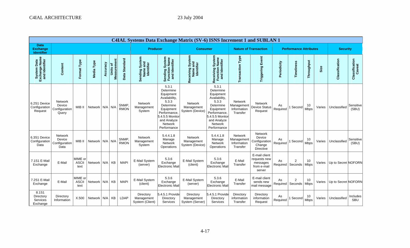
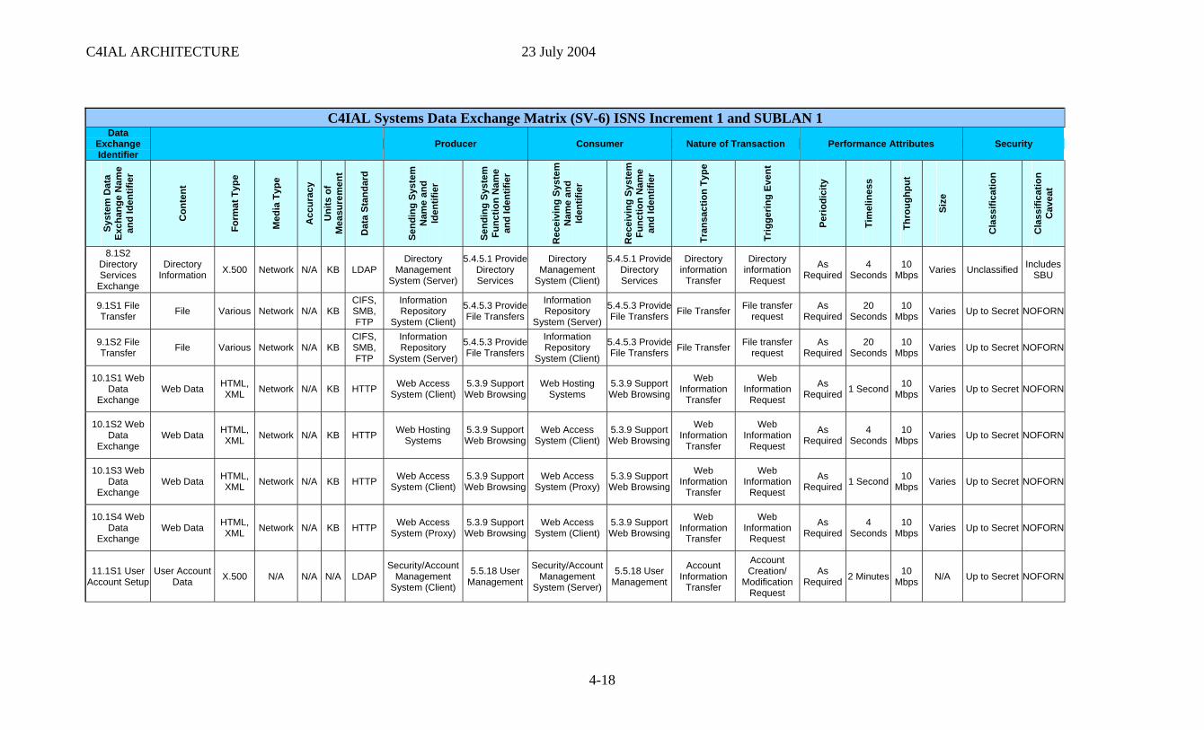
4.4.5 Systems Data Exchange Matrix (SV-6)
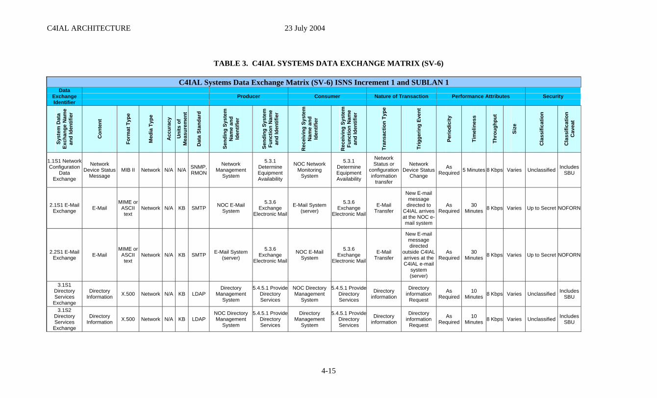
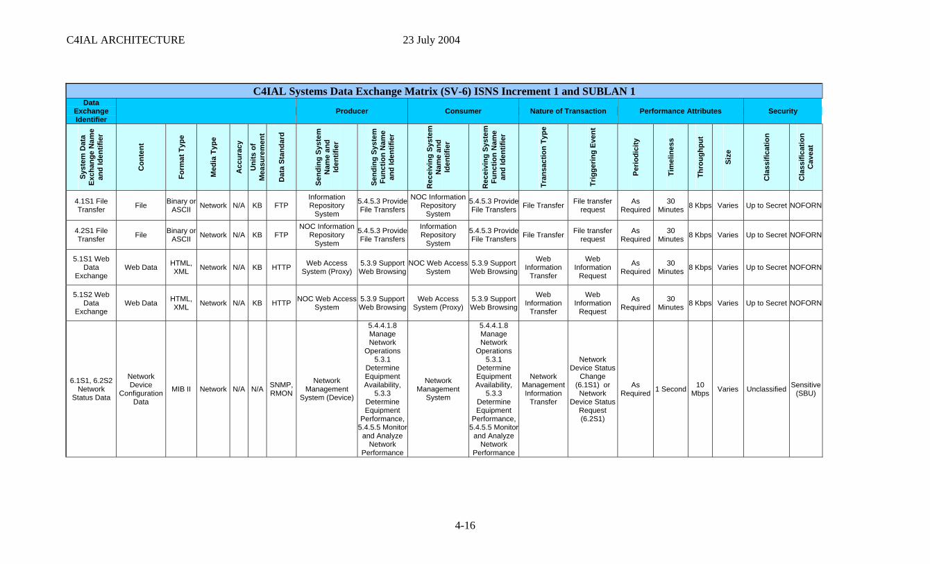
The Systems Data Exchange Matrix (SV-6) depicts information exchanges between systems within a node, and from those systems to systems at other nodes. The focus of the SV-6, however, is on how the data exchanges are (or will be) implemented in system-specific details covering such characteristics as specific protocols and data or media formats.
Table 3 provides the SV-6 for C4IAL. The SV-6 has been developed based on the IERs presented in the OV-3, and the mapping of UJTLs to System Functions provided in the SV-5. The C4IAL ORD does not explicitly require many system data exchanges listed in the SV-6 but the IERs are implicit underlying data exchanges needed to support the ORD requirements. Also, many of the system nodes listed in the SV-6 are components of the Compose software load.
4-13

C4IAL ARCHITECTURE 23 July 2004
This page intentionally left blank.
4-14
C4IAL ARCHITECTURE 23 July 2004
TABLE 3. C4IAL SYSTEMS DATA EXCHANGE MATRIX (SV-6)
C4IAL Systems Data Exchange Matrix (SV-6) ISNS Increment 1 and SUBLAN 1 Data
Exchange Identifier
Producer Consumer Nature of Transaction Performance Attributes Security
Syst
em D
ata
Exch
ange
Nam
e an
d Id
entif
ier
Con
tent
Form
at T
ype
Med
ia T
ype
Acc
urac
y
Uni
ts o
f M
easu
rem
ent
Dat
a St
anda
rd
Send
ing
Syst
em
Nam
e an
d Id
entif
ier
Send
ing
Syst
em
Func
tion
Nam
e a
Iden
tnd
ifier
Rec
eivi
ngte
m
Sys
Ne
and
am Iden
tifie
r
Rec
eivi
ngte
m
Sys
Fnc
tion
Nam
ue
and
Iden
tifie
r
Tran
sact
ion
Type
Trig
gerin
g Ev
ent
Perio
dici
ty
Tim
elin
ess
Thro
ughp
ut
Size
Cla
ssifi
catio
n
Cla
ssifi
catio
n C
avea
t
1.1S1 Network Configuration
Data Exchange
Network Device Status
Message MIB II Network N/A N/A SNMP,
RMON
Network Management
System
5.3.1 Determine Equipment Availability
NOC Network Monitoring
System
5.3.1 Determine Equipment Availability
Network Status or
configuration information
transfer
Network Device Status
Change
As Required 5 Minutes 8 Kbps Varies Unclassified Includes
SBU
2.1S1 E-Mail Exchange E-Mail
MIME or ASCII text
Network N/A KB SMTP NOC E-Mail System
5.3.6 Exchange
Electronic Mail
E-Mail System (server)
5.3.6 Exchange
Electronic Mail
E-Mail Transfer
New E-mail message
directed to C4IAL arrives at the NOC e-mail system
As Required
30 Minutes 8 Kbps Varies Up to Secret NOFORN
2.2S1 E-Mail Exchange E-Mail
MIME or ASCII text
Network N/A KB SMTP E-Mail System (server)
5.3.6 Exchange
Electronic Mail
NOC E-Mail System
5.3.6 Exchange
Electronic Mail
E-Mail Transfer
New E-mail message directed
outside C4IAL arrives at the C4IAL e-mail
system (server)
As Required
30 Minutes 8 Kbps Varies Up to Secret NOFORN
3.1S1 Directory Services
Exchange
Directory Information X.500 Network N/A KB LDAP
Directory Management
System
5.4.5.1 Provide Directory Services
NOC Directory Management
System
5.4.5.1 Provide Directory Services
Directory information
Directory information
Request
As Required
10 Minutes 8 Kbps Varies Unclassified Includes
SBU
3.1S2 Directory Services
Exchange
Directory Information X.500 Network N/A KB LDAP
NOC Directory Management
System
5.4.5.1 Provide Directory Services
Directory Management
System
5.4.5.1 Provide Directory Services
Directory information
Directory information
Request
As Required
10 Minutes 8 Kbps Varies Unclassified Includes
SBU
4-15
C4IAL ARCHITECTURE 23 July 2004
C4IAL Systems Data Exchange Matrix (SV-6) ISNS Increment 1 and SUBLAN 1 Data
Exchange Identifier
Producer Consumer Nature of Transaction Performance Attributes Security
Syst
em D
ata
Exch
ange
Nam
e an
d Id
entif
ier
Con
tent
Form
at T
ype
Med
ia T
ype
Acc
urac
y
Uni
ts o
f M
easu
rem
ent
Dat
a St
anda
rd
Send
ing
Syst
em
Nam
e an
d Id
entif
ier
Send
ing
Syst
em
Func
tion
Nam
e an
d Id
entif
ier
Rec
eivi
ng S
yste
m
Nam
e an
d Id
entif
ier
Rec
eivi
ng S
yste
m
Func
tion
Nam
e an
d Id
entif
ier
Tran
sact
ion
Type
Trig
gerin
g Ev
ent
Perio
dici
ty
Tim
elin
ess
Thro
ughp
ut
Size
Cla
ssifi
catio
n
Cla
ssifi
catio
n C
avea
t
4.1S1 File Transfer File Binary or
ASCII Network N/A KB FTP Information Repository
System
5.4.5.3 Provide File Transfers
NOC Information Repository
System
5.4.5.3 Provide File Transfers File Transfer File transfer
request As
Required30
Minutes 8 Kbps Varies Up to Secret NOFORN
4.2S1 File Transfer File Binary or
ASCII Network N/A KB FTP NOC Information
Repository System
5.4.5.3 Provide File Transfers
Information Repository
System
5.4.5.3 Provide File Transfers File Transfer File transfer
request As
Required30
Minutes 8 Kbps Varies Up to Secret NOFORN
5.1S1 Web Data
Exchange Web Data HTML,
XML Network N/A KB HTTP Web Access System (Proxy)
5.3.9 Support Web Browsing
NOC Web Access System
5.3.9 Support Web Browsing
Web Information
Transfer
Web Information
Request
As Required
30 Minutes 8 Kbps Varies Up to Secret NOFORN
5.1S2 Web Data
Exchange Web Data HTML,
XML Network N/A KB HTTP NOC Web Access System
5.3.9 Support Web Browsing
Web Access System (Proxy)
5.3.9 Support Web Browsing
Web Information
Transfer
Web Information
Request
As Required
30 Minutes 8 Kbps Varies Up to Secret NOFORN
6.1S1, 6.2S2 Network
Status Data
Network Device
Configuration Data
MIB II Network N/A N/A SNMP, RMON
Network Management
System (Device)
5.4.4.1.8 Manage Network
Operations 5.3.1
Determine Equipment Availability,
5.3.3 Determine Equipment
Performance, 5.4.5.5 Monitor
and Analyze Network
Performance
Network Management
System
5.4.4.1.8 Manage Network
Operations 5.3.1
Determine Equipment Availability,
5.3.3 Determine Equipment
Performance, 5.4.5.5 Monitor
and Analyze Network
Performance
Network Management Information
Transfer
Network Device Status
Change (6.1S1) or Network
Device Status Request (6.2S1)
As Required 1 Second 10
Mbps Varies Unclassified Sensitive (SBU)
4-16
C4IAL ARCHITECTURE 23 July 2004
C4IAL Systems Data Exchange Matrix (SV-6) ISNS Increment 1 and SUBLAN 1 Data
Exchange Identifier
Producer Consumer Nature of Transaction Performance Attributes Security
Syst
em D
ata
Exch
ange
Nam
e an
d Id
entif
ier
Con
tent
Form
at T
ype
Med
ia T
ype
Acc
urac
y
Uni
ts o
f M
easu
rem
ent
Dat
a St
anda
rd
Send
ing
Syst
em
Nam
e an
d Id
entif
ier
Send
ing
Syst
em
Func
tion
Nam
e an
d Id
entif
ier
Rec
eivi
ng S
yste
m
Nam
e an
d Id
entif
ier
Rec
eivi
ng S
yste
m
Func
tion
Nam
e an
d Id
entif
ier
Tran
sact
ion
Type
Trig
gerin
g Ev
ent
Perio
dici
ty
Tim
elin
ess
Thro
ughp
ut
Size
Cla
ssifi
catio
n
Cla
ssifi
catio
n C
avea
t
6.2S1 Device Configuration
Request
Network Device
Configuration Query
MIB II Network N/A N/A SNMP, RMON
Network Management
System
5.3.1 Determine Equipment Availability,
5.3.3 Determine Equipment
Performance, 5.4.5.5 Monitor
and Analyze Network
Performance
Network Management
System (Device)
5.3.1 Determine Equipment Availability,
5.3.3 Determine Equipment
Performance, 5.4.5.5 Monitor
and Analyze Network
Performance
Network Management Information
Transfer
Network Device Status
Request
As Required 1 Second 10
Mbps Varies Unclassified Sensitive (SBU)
6.3S1 Device Configuration
Data
Network Device
Configuration Data
MIB II Network N/A N/A SNMP, RMON
Network Management
System
5.4.4.1.8 Manage Network
Operations
Network Management
System (Device)
5.4.4.1.8 Manage Network
Operations
Network Management Information
Transfer
Network Device
Configuration Change Directive
As Required 1 Second 10
Mbps Varies Unclassified Sensitive (SBU)
7.1S1 E-Mail Exchange E-Mail
MIME or ASCII text
Network N/A KB MAPI E-Mail System (server)
5.3.6 Exchange
Electronic Mail
E-Mail System (client)
5.3.6 Exchange
Electronic Mail
E-Mail Transfer
E-mail client requests new
messages from e-mail
server
As Required
2 Seconds
10 Mbps Varies Up to Secret NOFORN
7.2S1 E-Mail Exchange E-Mail
MIME or ASCII text
Network N/A KB MAPI E-Mail System (client)
5.3.6 Exchange
Electronic Mail
E-Mail System (server)
5.3.6 Exchange
Electronic Mail
E-Mail Transfer
E-mail client sends new
mail message
As Required
2 Seconds
10 Mbps Varies Up to Secret NOFORN
8.1S1 Directory Services
Exchange
Directory Information X.500 Network N/A KB LDAP
Directory Management
System (Client)
5.4.5.1 Provide Directory Services
Directory Management
System (Server)
5.4.5.1 Provide Directory Services
Directory information
Transfer
Directory information
Request
As Required 1 Second 10
Mbps Varies Unclassified Includes SBU
4-17
C4IAL ARCHITECTURE 23 July 2004
C4IAL Systems Data Exchange Matrix (SV-6) ISNS Increment 1 and SUBLAN 1 Data
Exchange Identifier
Producer Consumer Nature of Transaction Performance Attributes Security
Syst
em D
ata
Exch
ange
Nam
e an
d Id
entif
ier
Con
tent
Form
at T
ype
Med
ia T
ype
Acc
urac
y
Uni
ts o
f M
easu
rem
ent
Dat
a St
anda
rd
Send
ing
Syst
em
Nam
e an
d Id
entif
ier
Send
ing
Syst
em
Func
tion
Nam
e an
d Id
entif
ier
Rec
eivi
ng S
yste
m
Nam
e an
d Id
entif
ier
Rec
eivi
ng S
yste
m
Func
tion
Nam
e an
d Id
entif
ier
Tran
sact
ion
Type
Trig
gerin
g Ev
ent
Perio
dici
ty
Tim
elin
ess
Thro
ughp
ut
Size
Cla
ssifi
catio
n
Cla
ssifi
catio
n C
avea
t
8.1S2 Directory Services
Exchange
Directory Information X.500 Network N/A KB LDAP
Directory Management
System (Server)
5.4.5.1 Provide Directory Services
Directory Management
System (Client)
5.4.5.1 Provide Directory Services
Directory information
Transfer
Directory information
Request
As Required
4 Seconds
10 Mbps Varies Unclassified Includes
SBU
9.1S1 File Transfer File Various Network N/A KB
CIFS, SMB, FTP
Information Repository
System (Client)
5.4.5.3 Provide File Transfers
Information Repository
System (Server)
5.4.5.3 Provide File Transfers File Transfer File transfer
request As
Required20
Seconds10
Mbps Varies Up to Secret NOFORN
9.1S2 File Transfer File Various Network N/A KB
CIFS, SMB, FTP
Information Repository
System (Server)
5.4.5.3 Provide File Transfers
Information Repository
System (Client)
5.4.5.3 Provide File Transfers File Transfer File transfer
request As
Required20
Seconds10
Mbps Varies Up to Secret NOFORN
10.1S1 Web Data
Exchange Web Data HTML,
XML Network N/A KB HTTP Web Access System (Client)
5.3.9 Support Web Browsing
Web Hosting Systems
5.3.9 Support Web Browsing
Web Information
Transfer
Web Information
Request
As Required 1 Second 10
Mbps Varies Up to Secret NOFORN
10.1S2 Web Data
Exchange Web Data HTML,
XML Network N/A KB HTTP Web Hosting Systems
5.3.9 Support Web Browsing
Web Access System (Client)
5.3.9 Support Web Browsing
Web Information
Transfer
Web Information
Request
As Required
4 Seconds
10 Mbps Varies Up to Secret NOFORN
10.1S3 Web Data
Exchange Web Data HTML,
XML Network N/A KB HTTP Web Access System (Client)
5.3.9 Support Web Browsing
Web Access System (Proxy)
5.3.9 Support Web Browsing
Web Information
Transfer
Web Information
Request
As Required 1 Second 10
Mbps Varies Up to Secret NOFORN
10.1S4 Web Data
Exchange Web Data HTML,
XML Network N/A KB HTTP Web Access System (Proxy)
5.3.9 Support Web Browsing
Web Access System (Client)
5.3.9 Support Web Browsing
Web Information
Transfer
Web Information
Request
As Required
4 Seconds
10 Mbps Varies Up to Secret NOFORN
11.1S1 User Account Setup
User Account Data X.500 N/A N/A N/A LDAP
Security/Account Management
System (Client)
5.5.18 User Management
Security/Account Management
System (Server)
5.5.18 User Management
Account Information
Transfer
Account Creation/
Modification Request
As Required 2 Minutes 10
Mbps N/A Up to Secret NOFORN
4-18
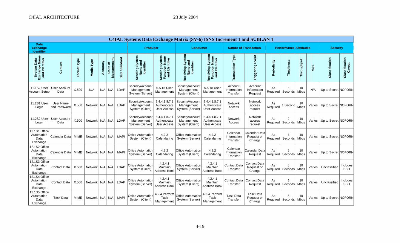
C4IAL ARCHITECTURE 23 July 2004
C4IAL Systems Data Exchange Matrix (SV-6) ISNS Increment 1 and SUBLAN 1 Data
Exchange Identifier
Producer Consumer Nature of Transaction Performance Attributes Security
Syst
em D
ata
Exch
ange
Nam
e an
d Id
entif
ier
Con
tent
Form
at T
ype
Med
ia T
ype
Acc
urac
y
Uni
ts o
f M
easu
rem
ent
Dat
a St
anda
rd
Send
ing
Syst
em
Nam
e an
d Id
entif
ier
Send
ing
Syst
em
Func
tion
Nam
e an
d Id
entif
ier
Rec
eivi
ng S
yste
m
Nam
e an
d Id
entif
ier
Rec
eivi
ng S
yste
m
Func
tion
Nam
e an
d Id
entif
ier
Tran
sact
ion
Type
Trig
gerin
g Ev
ent
Perio
dici
ty
Tim
elin
ess
Thro
ughp
ut
Size
Cla
ssifi
catio
n
Cla
ssifi
catio
n C
avea
t
11.1S2 User Account Setup
User Account Data X.500 N/A N/A N/A LDAP
Security/Account Management
System (Server)
5.5.18 User Management
Security/Account Management
System (Client)
5.5.18 User Management
Account Information
Transfer
Account Information
Request
As Required
5 Seconds
10 Mbps N/A Up to Secret NOFORN
11.2S1 User Login
User Name and Password X.500 Network N/A N/A LDAP
Security/Account Management
System (Client)
5.4.4.1.8.7.1 Authenticate User Access
Security/Account Management
System (Server)
5.4.4.1.8.7.1 Authenticate User Access
Network Access
Network access request
As Required 1 Second 10
Mbps Varies Up to Secret NOFORN
11.2S2 User Login
User Account Data X.500 Network N/A N/A LDAP
Security/Account Management
System (Server)
5.4.4.1.8.7.1 Authenticate User Access
Security/Account Management
System (Client)
5.4.4.1.8.7.1 Authenticate User Access
Network Access
Network access request
As Required
9 Seconds
10 Mbps Varies Up to Secret NOFORN
12.1S1 Office Automation
Data Exchange
Calendar Data MIME Network N/A N/A MAPI Office AutomationSystem (Client)
4.2.2 Calendaring
Office Automation System (Server)
4.2.2 Calendaring
Calendar Information
Transfer
Calendar Data Request or
Change
As Required
5 Seconds
10 Mbps Varies Up to Secret NOFORN
12.1S2 Office Automation
Data Exchange
Calendar Data MIME Network N/A N/A MAPI Office Automation System (Server)
4.2.2 Calendaring
Office Automation System (Client)
4.2.2 Calendaring
Calendar Information
Transfer
Calendar Data Request
As Required
5 Seconds
10 Mbps Varies Up to Secret NOFORN
12.1S3 Office Automation
Data Exchange
Contact Data X.500 Network N/A N/A LDAP Office Automation System (Client)
4.2.4.1 Maintain
Address Book
Office Automation System (Server)
4.2.4.1 Maintain
Address Book
Contact Data Transfer
Contact Data Request or
Change
As Required
5 Seconds
10 Mbps Varies Unclassified Includes
SBU
12.1S4 Office Automation
Data Exchange
Contact Data X.500 Network N/A N/A LDAP Office Automation System (Server)
4.2.4.1 Maintain
Address Book
Office Automation System (Client)
4.2.4.1 Maintain
Address Book
Contact Data Transfer
Contact Data Request
As Required
5 Seconds
10 Mbps Varies Unclassified Includes
SBU
12.1S5 Office Automation
Data Exchange
Task Data MIME Network N/A N/A MAPI Office Automation System (Client)
4.2.4 Perform Task
Management
Office Automation System (Server)
4.2.4 Perform Task
Management
Task Data Transfer
Task Data Request or
Change
As Required
5 Seconds
10 Mbps Varies Up to Secret NOFORN
4-19
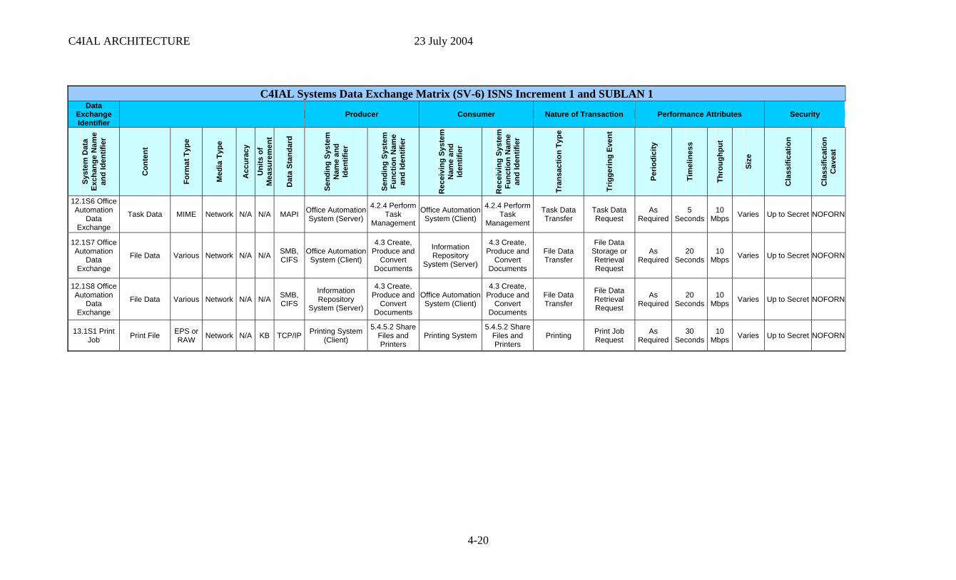
C4IAL ARCHITECTURE 23 July 2004
C4IAL Systems Data Exchange Matrix (SV-6) ISNS Increment 1 and SUBLAN 1 Data
Exchange Identifier
Producer Consumer Nature of Transaction Performance Attributes Security
Syst
em D
ata
Exch
ange
Nam
e an
d Id
entif
ier
Con
tent
Form
at T
ype
Med
ia T
ype
Acc
urac
y
Uni
ts o
f M
easu
rem
ent
Dat
a St
anda
rd
Send
ing
Syst
em
Nam
e an
d Id
entif
ier
Send
ing
Syst
em
Func
tion
Nam
e an
d Id
entif
ier
Rec
eivi
ng S
yste
m
Nam
e an
d Id
entif
ier
Rec
eivi
ng S
yste
m
Func
tion
Nam
e an
d Id
entif
ier
Tran
sact
ion
Type
Trig
gerin
g Ev
ent
Perio
dici
ty
Tim
elin
ess
Thro
ughp
ut
Size
Cla
ssifi
catio
n
Cla
ssifi
catio
n C
avea
t
12.1S6 Office Automation
Data Exchange
Task Data MIME Network N/A N/A MAPI Office Automation System (Server)
4.2.4 Perform Task
Management
Office Automation System (Client)
4.2.4 Perform Task
Management
Task Data Transfer
Task Data Request
As Required
5 Seconds
10 Mbps Varies Up to Secret NOFORN
12.1S7 Office Automation
Data Exchange
File Data Various Network N/A N/A SMB, CIFS
Office Automation System (Client)
4.3 Create, Produce and
Convert Documents
Information Repository
System (Server)
4.3 Create, Produce and
Convert Documents
File Data Transfer
File Data Storage or Retrieval Request
As Required
20 Seconds
10 Mbps Varies Up to Secret NOFORN
12.1S8 Office Automation
Data Exchange
File Data Various Network N/A N/A SMB, CIFS
Information Repository
System (Server)
4.3 Create, Produce and
Convert Documents
Office Automation System (Client)
4.3 Create, Produce and
Convert Documents
File Data Transfer
File Data Retrieval Request
As Required
20 Seconds
10 Mbps Varies Up to Secret NOFORN
13.1S1 Print Job Print File EPS or
RAW Network N/A KB TCP/IP Printing System (Client)
5.4.5.2 Share Files and Printers
Printing System 5.4.5.2 Share
Files and Printers
Printing Print Job Request
As Required
30 Seconds
10 Mbps Varies Up to Secret NOFORN
4-20
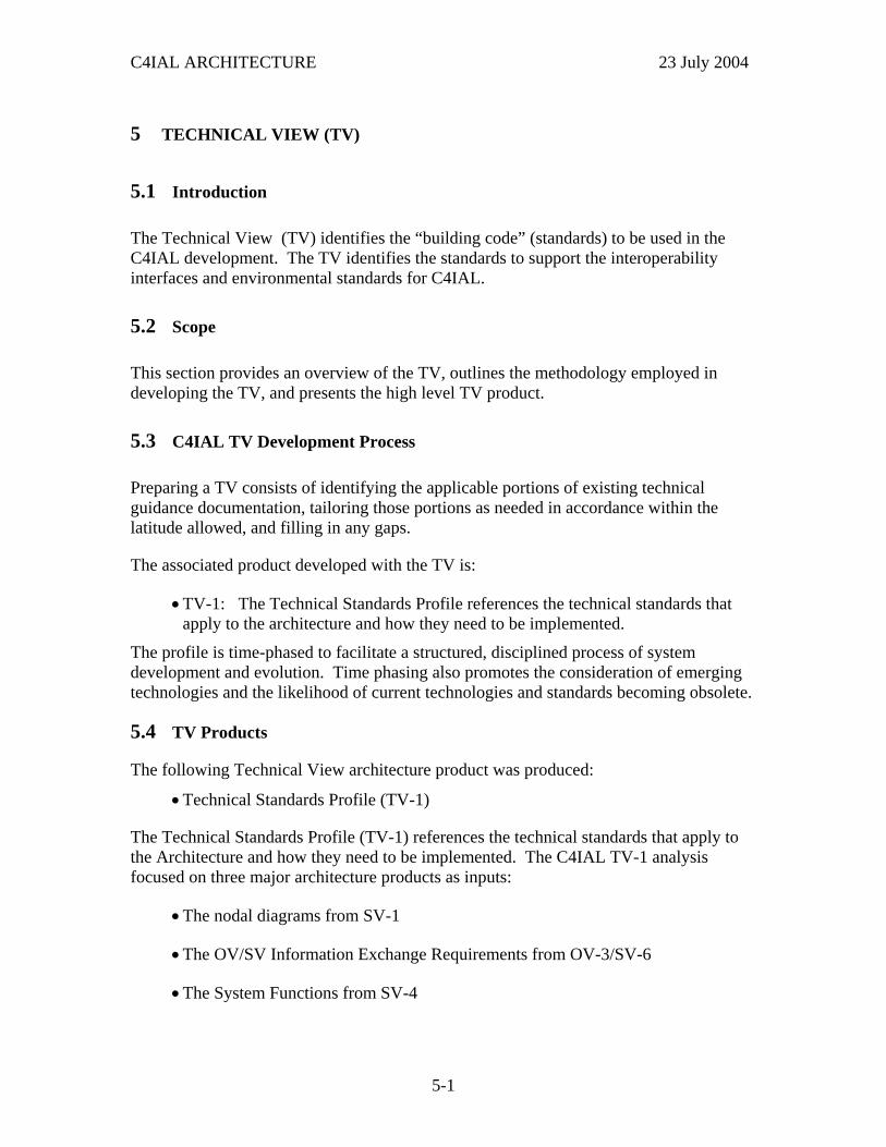
C4IAL ARCHITECTURE 23 July 2004
5 TECHNICAL VIEW (TV)
5.1 Introduction
The Technical View (TV) identifies the “building code” (standards) to be used in the C4IAL development. The TV identifies the standards to support the interoperability interfaces and environmental standards for C4IAL.
5.2 Scope
This section provides an overview of the TV, outlines the methodology employed in developing the TV, and presents the high level TV product.
5.3 C4IAL TV Development Process
Preparing a TV consists of identifying the applicable portions of existing technical guidance documentation, tailoring those portions as needed in accordance within the latitude allowed, and filling in any gaps.
The associated product developed with the TV is:
• TV-1: The Technical Standards Profile references the technical standards that apply to the architecture and how they need to be implemented.
The profile is time-phased to facilitate a structured, disciplined process of system development and evolution. Time phasing also promotes the consideration of emerging technologies and the likelihood of current technologies and standards becoming obsolete.
5.4 TV Products
The following Technical View architecture product was produced:
• Technical Standards Profile (TV-1)
The Technical Standards Profile (TV-1) references the technical standards that apply to the Architecture and how they need to be implemented. The C4IAL TV-1 analysis focused on three major architecture products as inputs:
• The nodal diagrams from SV-1
• The OV/SV Information Exchange Requirements from OV-3/SV-6
• The System Functions from SV-4
5-1
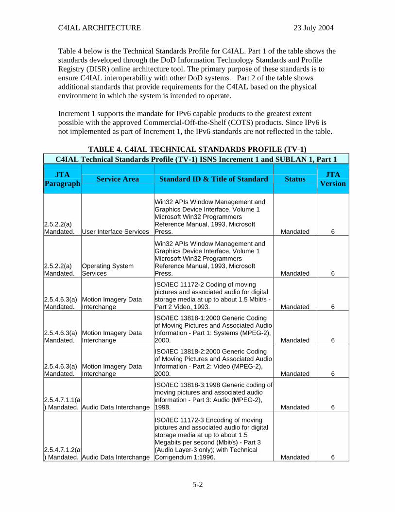
C4IAL ARCHITECTURE 23 July 2004
Table 4 below is the Technical Standards Profile for C4IAL. Part 1 of the table shows tstandards developed through the DoD Information Technology Standards and ProfiRegistry (DISR) online architecture tool. The primary purpose of these standards is tensure C4IAL interoperability with other DoD systems.
he le
o Part 2 of the table shows
dditional standards that provide requirements for the C4IAL based on the physical
ossible with the approved Commercial-Off-the-Shelf (COTS) products. Since IPv6 is not imple e table.
TABLE 4. C4IAL TECHNICAL STANDARDS PROFILE (TV-1)
aenvironment in which the system is intended to operate. Increment 1 supports the mandate for IPv6 capable products to the greatest extent p
mented as part of Increment 1, the IPv6 standards are not reflected in th
C4IAL Tech s Pr SU 1, Pnical Standard ofile (TV-1) ISNS Increment 1 and BLAN art 1
JTA Paragraph Service Area Standard ID & Title of Standard Status JTA
Version
2.5.2.2(a) Mandated. User Interface Services
nd
ft Win32 Programmers
Mandated 6
Win32 APIs Window Management aGraphics Device Interface, Volume 1MicrosoReference Manual, 1993, Microsoft Press.
2.5.2.2(a) Mandated.
Operating System Services
ft Win32 Programmers
Mandated 6
Win32 APIs Window Management and Graphics Device Interface, Volume 1MicrosoReference Manual, 1993, Microsoft Press.
2.5.4.6.3(a) Mandated.
Motion Imagery Data Interchange
ted audio for digital
Mandated 6
ISO/IEC 11172-2 Coding of moving pictures and associastorage media at up to about 1.5 Mbit/s -Part 2 Video, 1993.
2.5.4.6.3(a) Mandated.
Motion Imagery Data Interchange
ing Pictures and Associated Audio
Mandated 6
ISO/IEC 13818-1:2000 Generic Coding of MovInformation - Part 1: Systems (MPEG-2),2000.
2.5.4.6.3(a) Mandated.
Motion Imagery Data Interchange
ing Pictures and Associated Audio
Mandated 6
ISO/IEC 13818-2:2000 Generic Codingof MovInformation - Part 2: Video (MPEG-2), 2000.
2.5.4.7.1.1(a) Mandated. Audio Data Interchange
of pictures and associated audio
Mandated 6
ISO/IEC 13818-3:1998 Generic codingmovinginformation - Part 3: Audio (MPEG-2), 1998.
2.5.4.7.1.2(a) Mandated. Audio Data Interchange
l
Mbit/s) - Part 3 (Audio Layer-3 only); with Technical Corrigendum 1:1996. Mandated 6
ISO/IEC 11172-3 Encoding of moving pictures and associated audio for digitastorage media at up to about 1.5 Megabits per second (
5-2
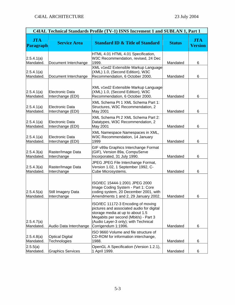
C4IAL ARCHITECTURE 23 July 2004
C4IAL Technical Standards Profile (TV-1) ISNS Increment 1 and SUBLAN 1, Part 1
JTA Paragraph Service Area Standard ID & Title of Standard Status JTA
Version
2.5.4.1(a) Mandated. Document Interchange
HTML 4.01 HTML 4.01 Specification, W3C Recommendation, revised, 24 Dec 1999. Mandated 6
2.5.4.1(a) Mandated. Document Interchange
XML v1ed2 Extensible Markup Language (XML) 1.0, (Second Edition), W3C Recommendation, 6 October 2000. Mandated 6
2.5.4.1(a) Mandated.
Electronic Data Interchange (EDI)
XML v1ed2 Extensible Markup Language (XML) 1.0, (Second Edition), W3C Recommendation, 6 October 2000. Mandated 6
2.5.4.1(a) Mandated.
Electronic Data Interchange (EDI)
XML Schema Pt 1 XML Schema Part 1: Structures, W3C Recommendation, 2 May 2001 Mandated 6
2.5.4.1(a) Mandated.
Electronic Data Interchange (EDI)
XML Schema Pt 2 XML Schema Part 2: Datatypes, W3C Recommendation, 2 May 2001 Mandated 6
2.5.4.1(a) Mandated.
Electronic Data Interchange (EDI)
XML Namespace Namespaces in XML, W3C Recommendation, 14 January 1999 Mandated 6
2.5.4.3(a) Mandated.
Raster/Image Data Interchange
GIF v89a Graphics Interchange Format (GIF), Version 89a, CompuServe Incorporated, 31 July 1990. Mandated 6
2.5.4.3(a) Mandated.
Raster/Image Data Interchange
JPEG JPEG File Interchange Format, Version 1.02, 1 September 1992, C-Cube Microsystems. Mandated 6
2.5.4.5(a) Mandated.
Still Imagery Data Interchange
ISO/IEC 15444-1:2001 JPEG 2000 Image Coding System - Part 1: Core coding system, 20 December 2001, with Amendments 1 and 2, 29 January 2002. Mandated 6
2.5.4.7(a) Mandated. Audio Data Interchange
ISO/IEC 11172-3 Encoding of moving pictures and associated audio for digital storage media at up to about 1.5 Megabits per second (Mbit/s) - Part 3 (Audio Layer-3 only); with Technical Corrigendum 1:1996. Mandated 6
2.5.4.8(a) Mandated.
Optical Digital Technologies
ISO 9660 Volume and file structure of CD-ROM for information interchange, 1988. Mandated 6
2.5.5(a) Mandated. Graphics Services
OpenGL A Specification (Version 1.2.1), 1 April 1999. Mandated 6
5-3
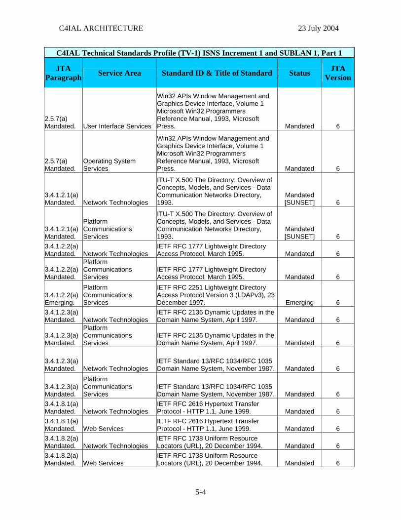
C4IAL ARCHITECTURE 23 July 2004
C4IAL Technical Standards Profile (TV-1) ISNS Increment 1 and SUBLAN 1, Part 1
JTA Paragraph Service Area Standard ID & Title of Standard Status JTA
Version
2.5.7(a) Mandated. User Interface Services
Win32 APIs Window Management and Graphics Device Interface, Volume 1 Microsoft Win32 Programmers Reference Manual, 1993, Microsoft Press. Mandated 6
2.5.7(a) Mandated.
Operating System Services
Win32 APIs Window Management and Graphics Device Interface, Volume 1 Microsoft Win32 Programmers Reference Manual, 1993, Microsoft Press. Mandated 6
3.4.1.2.1(a) Mandated. Network Technologies
ITU-T X.500 The Directory: Overview of Concepts, Models, and Services - Data Communication Networks Directory, 1993.
Mandated [SUNSET] 6
3.4.1.2.1(a) Mandated.
Platform Communications Services
ITU-T X.500 The Directory: Overview of Concepts, Models, and Services - Data Communication Networks Directory, 1993.
Mandated [SUNSET] 6
3.4.1.2.2(a) Mandated. Network Technologies
IETF RFC 1777 Lightweight Directory Access Protocol, March 1995. Mandated 6
3.4.1.2.2(a) Mandated.
Platform Communications Services
IETF RFC 1777 Lightweight Directory Access Protocol, March 1995. Mandated 6
3.4.1.2.2(a) Emerging.
Platform Communications Services
IETF RFC 2251 Lightweight Directory Access Protocol Version 3 (LDAPv3), 23 December 1997. Emerging 6
3.4.1.2.3(a) Mandated. Network Technologies
IETF RFC 2136 Dynamic Updates in the Domain Name System, April 1997. Mandated 6
3.4.1.2.3(a) Mandated.
Platform Communications Services
IETF RFC 2136 Dynamic Updates in the Domain Name System, April 1997. Mandated 6
3.4.1.2.3(a) Mandated. Network Technologies
IETF Standard 13/RFC 1034/RFC 1035 Domain Name System, November 1987. Mandated 6
3.4.1.2.3(a) Mandated.
Platform Communications Services
IETF Standard 13/RFC 1034/RFC 1035 Domain Name System, November 1987. Mandated 6
3.4.1.8.1(a) Mandated. Network Technologies
IETF RFC 2616 Hypertext Transfer Protocol - HTTP 1.1, June 1999. Mandated 6
3.4.1.8.1(a) Mandated. Web Services
IETF RFC 2616 Hypertext Transfer Protocol - HTTP 1.1, June 1999. Mandated 6
3.4.1.8.2(a) Mandated. Network Technologies
IETF RFC 1738 Uniform Resource Locators (URL), 20 December 1994. Mandated 6
3.4.1.8.2(a) Mandated. Web Services
IETF RFC 1738 Uniform Resource Locators (URL), 20 December 1994. Mandated 6
5-4

C4IAL ARCHITECTURE 23 July 2004
C4IAL Technical Standards Profile (TV-1) ISNS Increment 1 and SUBLAN 1, Part 1
JTA Paragraph Service Area Standard ID & Title of Standard Status JTA
Version
3.4.1.10.1(a) Mandated. Network Technologies
IETF RFC 2581 TCP Congestion Control, April 1999. Mandated 6
3.4.1.10.1(a) Mandated. Network Technologies
IETF Standard 7/RFC 793 Transmission Control Protocol, September 1981. Mandated 6
3.4.1.10.2(a) Mandated. Network Technologies
IETF Standard 6/RFC 768 User Datagram Protocol, 28 August 1980. Mandated 6
3.4.1.1(a) Mandated.
Platform Communications Services
IETF RFC 1870 Simple Mail Transfer Protocol Services Extension for Message Size Declaration, November 1995 Mandated 6
3.4.1.1(a) Mandated. Network Technologies
IETF RFC 1870 Simple Mail Transfer Protocol Services Extension for Message Size Declaration, November 1995 Mandated 6
3.4.1.1(a) Mandated. Electronic Mail
IETF RFC 1870 Simple Mail Transfer Protocol Services Extension for Message Size Declaration, November 1995 Mandated 6
3.4.1.1(a) Mandated.
Platform Communications Services
IETF RFC 2821 Simple Mail transfer Protocol, April 2001. Mandated 6
3.4.1.1(a) Mandated. Network Technologies
IETF RFC 2821 Simple Mail transfer Protocol, April 2001. Mandated 6
3.4.1.1(a) Mandated. Electronic Mail
IETF RFC 2821 Simple Mail transfer Protocol, April 2001. Mandated 6
3.4.1.1(a) Mandated.
Platform Communications Services
IETF RFC 2822 Internet Message Format, April 2001. Mandated 6
3.4.1.1(a) Mandated. Network Technologies
IETF RFC 2822 Internet Message Format, April 2001. Mandated 6
3.4.1.1(a) Mandated. Electronic Mail
IETF RFC 2822 Internet Message Format, April 2001. Mandated 6
3.4.1.1(a) Mandated. Network Technologies
IETF RFCs 2045-2049 Multipurpose Internet Mail Extensions (MIME) Parts 1-5, November 1996. Mandated 6
3.4.1.1(a) Mandated.
Platform Communications Services
IETF RFCs 2045-2049 Multipurpose Internet Mail Extensions (MIME) Parts 1-5, November 1996. Mandated 6
3.4.1.1(a) Mandated. Electronic Mail
IETF RFCs 2045-2049 Multipurpose Internet Mail Extensions (MIME) Parts 1-5, November 1996. Mandated 6
3.4.1.11(a) Mandated. Network Technologies
IETF RFC 2236 Internet Group Management Protocol, Version 2 (IGMPv2), November 1997. Mandated 6
5-5
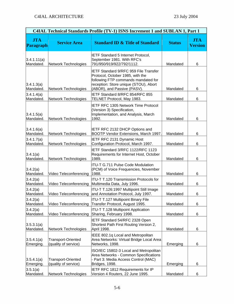
C4IAL ARCHITECTURE 23 July 2004
C4IAL Technical Standards Profile (TV-1) ISNS Increment 1 and SUBLAN 1, Part 1
JTA Paragraph Service Area Standard ID & Title of Standard Status JTA
Version
3.4.1.11(a) Mandated. Network Technologies
IETF Standard 5 Internet Protocol, September 1981. With RFC's 791/950/919/922/792/1112. Mandated 6
3.4.1.3(a) Mandated. Network Technologies
IETF Standard 9/RFC 959 File Transfer Protocol, October 1985, with the following FTP commands mandated for reception: Store unique (STOU), Abort (ABOR), and Passive (PASV). Mandated 6
3.4.1.4(a) Mandated. Network Technologies
IETF Standard 8/RFC 854/RFC 855 TELNET Protocol, May 1983. Mandated 6
3.4.1.5(a) Mandated. Network Technologies
IETF RFC 1305 Network Time Protocol (Version 3) Specification, Implementation, and Analysis, March 1992. Mandated 6
3.4.1.6(a) Mandated. Network Technologies
IETF RFC 2132 DHCP Options and BOOTP Vendor Extensions, March 1997. Mandated 6
3.4.1.7(a) Mandated. Network Technologies
IETF RFC 2131 Dynamic Host Configuration Protocol, March 1997. Mandated 6
3.4.1(a) Mandated. Network Technologies
IETF Standard 3/RFC 1122/RFC 1123 Requirements for Internet Host, October 1989. Mandated 6
3.4.2(a) Mandated. Video Teleconferencing
ITU-T G.711 Pulse Code Modulation (PCM) of Voice Frequencies, November 1988. Mandated 6
3.4.2(a) Mandated. Video Teleconferencing
ITU-T T.120 Transmission Protocols for Multimedia Data, July 1996. Mandated 6
3.4.2(a) Mandated. Video Teleconferencing
ITU-T T.126:1997 Multipoint Still Image and Annotation Protocol, July 1997. Mandated 6
3.4.2(a) Mandated. Video Teleconferencing
ITU-T T.127 Multipoint Binary File Transfer Protocol, August 1995. Mandated 6
3.4.2(a) Mandated. Video Teleconferencing
ITU-T T.128 Multipoint Application Sharing, February 1998. Mandated 6
3.5.3.1(a) Mandated. Network Technologies
IETF Standard 54/RFC 2328 Open Shortest Path First Routing Version 2, April 1998. Mandated 6
3.5.4.1(a) Emerging.
Transport-Oriented (quality of service)
IEEE 802.1q Local and Metropolitan Area Networks: Virtual Bridge Local Area Networks, 1998. Emerging 6
3.5.4.1(a) Emerging.
Transport-Oriented (quality of service)
ISO/IEC 15802-3 Local and Metropolitan Area Networks - Common Specifications - Part 3: Media Access Control (MAC) Bridges, 1998. Emerging 6
3.5.1(a) Mandated. Network Technologies
IETF RFC 1812 Requirements for IP Version 4 Routers, 22 June 1995. Mandated 6
5-6
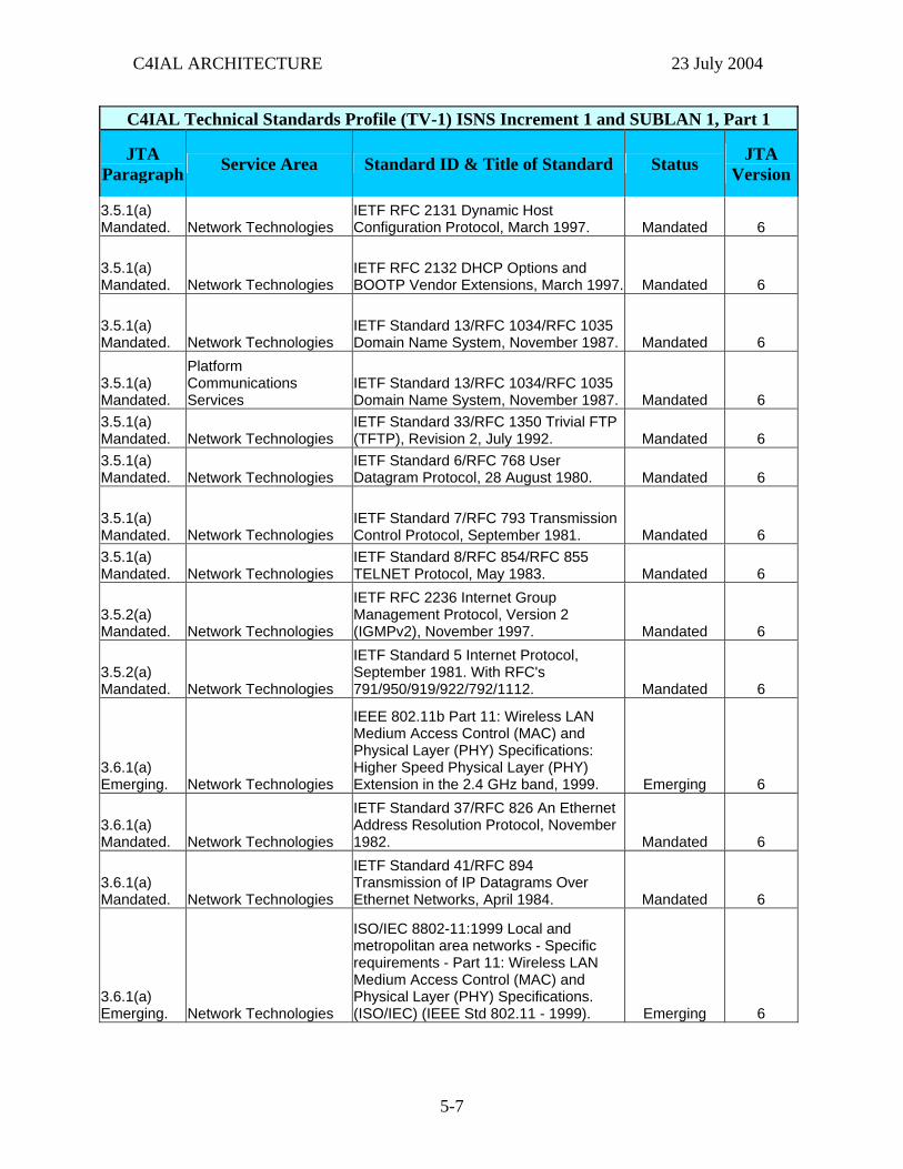
C4IAL ARCHITECTURE 23 July 2004
C4IAL Technical Standards Profile (TV-1) ISNS Increment 1 and SUBLAN 1, Part 1
JTA Paragraph Service Area Standard ID & Title of Standard Status JTA
Version
3.5.1(a) Mandated. Network Technologies
IETF RFC 2131 Dynamic Host Configuration Protocol, March 1997. Mandated 6
3.5.1(a) Mandated. Network Technologies
IETF RFC 2132 DHCP Options and BOOTP Vendor Extensions, March 1997. Mandated 6
3.5.1(a) Mandated. Network Technologies
IETF Standard 13/RFC 1034/RFC 1035 Domain Name System, November 1987. Mandated 6
3.5.1(a) Mandated.
Platform Communications Services
IETF Standard 13/RFC 1034/RFC 1035 Domain Name System, November 1987. Mandated 6
3.5.1(a) Mandated. Network Technologies
IETF Standard 33/RFC 1350 Trivial FTP (TFTP), Revision 2, July 1992. Mandated 6
3.5.1(a) Mandated. Network Technologies
IETF Standard 6/RFC 768 User Datagram Protocol, 28 August 1980. Mandated 6
3.5.1(a) Mandated. Network Technologies
IETF Standard 7/RFC 793 Transmission Control Protocol, September 1981. Mandated 6
3.5.1(a) Mandated. Network Technologies
IETF Standard 8/RFC 854/RFC 855 TELNET Protocol, May 1983. Mandated 6
3.5.2(a) Mandated. Network Technologies
IETF RFC 2236 Internet Group Management Protocol, Version 2 (IGMPv2), November 1997. Mandated 6
3.5.2(a) Mandated. Network Technologies
IETF Standard 5 Internet Protocol, September 1981. With RFC's 791/950/919/922/792/1112. Mandated 6
3.6.1(a) Emerging. Network Technologies
IEEE 802.11b Part 11: Wireless LAN Medium Access Control (MAC) and Physical Layer (PHY) Specifications: Higher Speed Physical Layer (PHY) Extension in the 2.4 GHz band, 1999. Emerging 6
3.6.1(a) Mandated. Network Technologies
IETF Standard 37/RFC 826 An Ethernet Address Resolution Protocol, November 1982. Mandated 6
3.6.1(a) Mandated. Network Technologies
IETF Standard 41/RFC 894 Transmission of IP Datagrams Over Ethernet Networks, April 1984. Mandated 6
3.6.1(a) Emerging. Network Technologies
ISO/IEC 8802-11:1999 Local and metropolitan area networks - Specific requirements - Part 11: Wireless LAN Medium Access Control (MAC) and Physical Layer (PHY) Specifications. (ISO/IEC) (IEEE Std 802.11 - 1999). Emerging 6
5-7
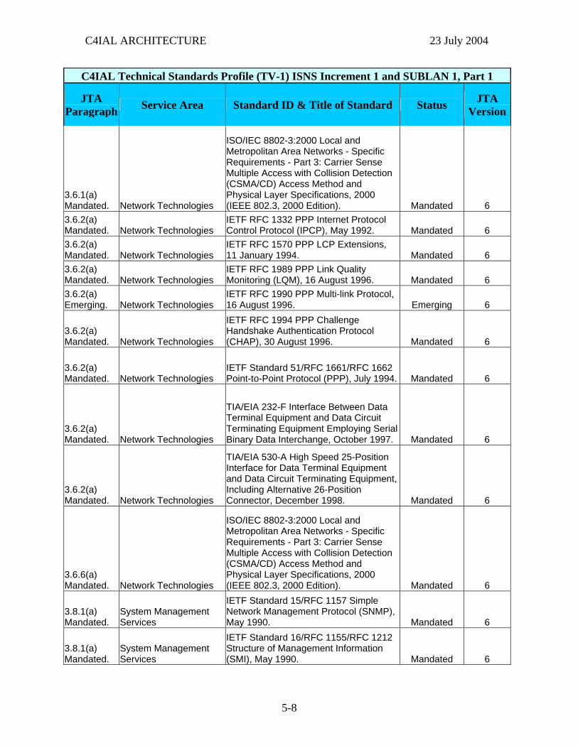
C4IAL ARCHITECTURE 23 July 2004
C4IAL Technical Standards Profile (TV-1) ISNS Increment 1 and SUBLAN 1, Part 1
JTA Paragraph Service Area Standard ID & Title of Standard Status JTA
Version
3.6.1(a) Mandated. Network Technologies
ISO/IEC 8802-3:2000 Local and Metropolitan Area Networks - Specific Requirements - Part 3: Carrier Sense Multiple Access with Collision Detection (CSMA/CD) Access Method and Physical Layer Specifications, 2000 (IEEE 802.3, 2000 Edition). Mandated 6
3.6.2(a) Mandated. Network Technologies
IETF RFC 1332 PPP Internet Protocol Control Protocol (IPCP), May 1992. Mandated 6
3.6.2(a) Mandated. Network Technologies
IETF RFC 1570 PPP LCP Extensions, 11 January 1994. Mandated 6
3.6.2(a) Mandated. Network Technologies
IETF RFC 1989 PPP Link Quality Monitoring (LQM), 16 August 1996. Mandated 6
3.6.2(a) Emerging. Network Technologies
IETF RFC 1990 PPP Multi-link Protocol, 16 August 1996. Emerging 6
3.6.2(a) Mandated. Network Technologies
IETF RFC 1994 PPP Challenge Handshake Authentication Protocol (CHAP), 30 August 1996. Mandated 6
3.6.2(a) Mandated. Network Technologies
IETF Standard 51/RFC 1661/RFC 1662 Point-to-Point Protocol (PPP), July 1994. Mandated 6
3.6.2(a) Mandated. Network Technologies
TIA/EIA 232-F Interface Between Data Terminal Equipment and Data Circuit Terminating Equipment Employing Serial Binary Data Interchange, October 1997. Mandated 6
3.6.2(a) Mandated. Network Technologies
TIA/EIA 530-A High Speed 25-Position Interface for Data Terminal Equipment and Data Circuit Terminating Equipment, Including Alternative 26-Position Connector, December 1998. Mandated 6
3.6.6(a) Mandated. Network Technologies
ISO/IEC 8802-3:2000 Local and Metropolitan Area Networks - Specific Requirements - Part 3: Carrier Sense Multiple Access with Collision Detection (CSMA/CD) Access Method and Physical Layer Specifications, 2000 (IEEE 802.3, 2000 Edition). Mandated 6
3.8.1(a) Mandated.
System Management Services
IETF Standard 15/RFC 1157 Simple Network Management Protocol (SNMP), May 1990. Mandated 6
3.8.1(a) Mandated.
System Management Services
IETF Standard 16/RFC 1155/RFC 1212 Structure of Management Information (SMI), May 1990. Mandated 6
5-8
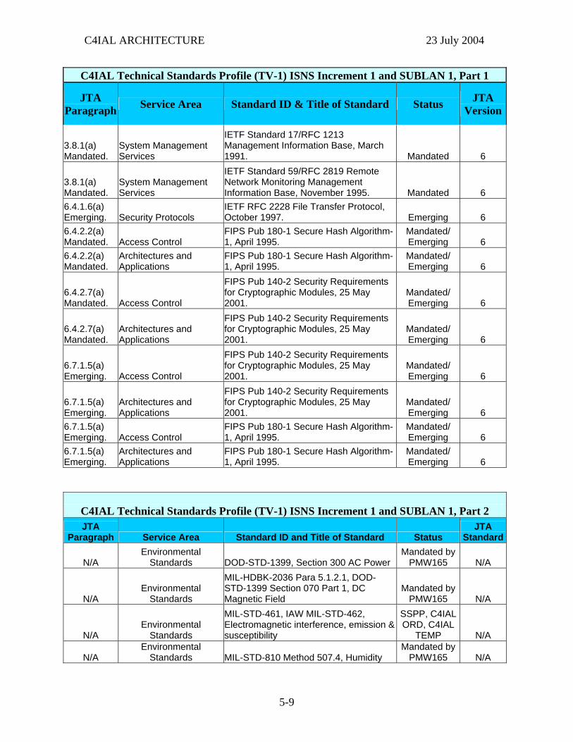
C4IAL ARCHITECTURE 23 July 2004
C4IAL Technical Standards Profile (TV-1) ISNS Increment 1 and SUBLAN 1, Part 1
JTA Paragraph Service Area Standard ID & Title of Standard Status JTA
Version
3.8.1(a) Mandated.
System Management Services
IETF Standard 17/RFC 1213 Management Information Base, March 1991. Mandated 6
3.8.1(a) Mandated.
System Management Services
IETF Standard 59/RFC 2819 Remote Network Monitoring Management Information Base, November 1995. Mandated 6
6.4.1.6(a) Emerging. Security Protocols
IETF RFC 2228 File Transfer Protocol, October 1997. Emerging 6
6.4.2.2(a) Mandated. Access Control
FIPS Pub 180-1 Secure Hash Algorithm-1, April 1995.
Mandated/ Emerging 6
6.4.2.2(a) Mandated.
Architectures and Applications
FIPS Pub 180-1 Secure Hash Algorithm-1, April 1995.
Mandated/ Emerging 6
6.4.2.7(a) Mandated. Access Control
FIPS Pub 140-2 Security Requirements for Cryptographic Modules, 25 May 2001.
Mandated/ Emerging 6
6.4.2.7(a) Mandated.
Architectures and Applications
FIPS Pub 140-2 Security Requirements for Cryptographic Modules, 25 May 2001.
Mandated/ Emerging 6
6.7.1.5(a) Emerging. Access Control
FIPS Pub 140-2 Security Requirements for Cryptographic Modules, 25 May 2001.
Mandated/ Emerging 6
6.7.1.5(a) Emerging.
Architectures and Applications
FIPS Pub 140-2 Security Requirements for Cryptographic Modules, 25 May 2001.
Mandated/ Emerging 6
6.7.1.5(a) Emerging. Access Control
FIPS Pub 180-1 Secure Hash Algorithm-1, April 1995.
Mandated/ Emerging 6
6.7.1.5(a) Emerging.
Architectures and Applications
FIPS Pub 180-1 Secure Hash Algorithm-1, April 1995.
Mandated/ Emerging 6
C4IAL Technical Standards Profile (TV-1) ISNS Increment 1 and SUBLAN 1, Part 2 JTA
Paragraph Service Area Standard ID and Title of Standard Status JTA
Standard
N/A Environmental
Standards DOD-STD-1399, Section 300 AC Power Mandated by
PMW165 N/A
N/A Environmental
Standards
MIL-HDBK-2036 Para 5.1.2.1, DOD-STD-1399 Section 070 Part 1, DC Magnetic Field
Mandated by PMW165 N/A
N/A Environmental
Standards
MIL-STD-461, IAW MIL-STD-462, Electromagnetic interference, emission & susceptibility
SSPP, C4IAL ORD, C4IAL
TEMP N/A
N/A Environmental
Standards MIL-STD-810 Method 507.4, Humidity Mandated by
PMW165 N/A
5-9
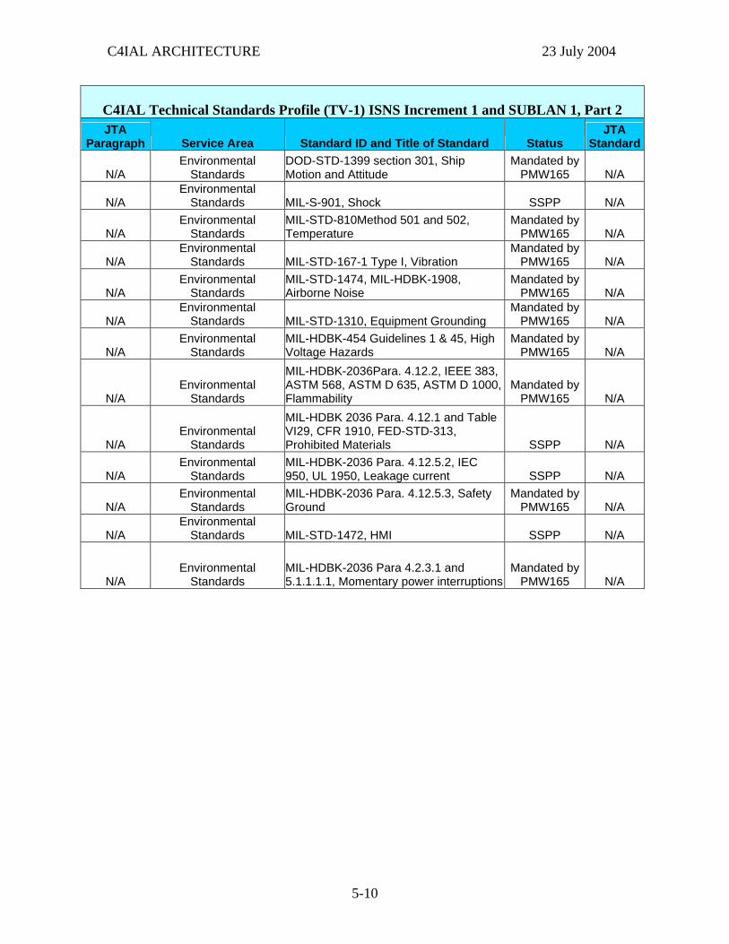
C4IAL ARCHITECTURE 23 July 2004
C4IAL Technical Standards Profile (TV-1) ISNS Increment 1 and SUBLAN 1, Part 2 JTA
Paragraph Service Area Standard ID and Title of Standard Status JTA
Standard
N/A Environmental
Standards DOD-STD-1399 section 301, Ship Motion and Attitude
Mandated by PMW165 N/A
N/A Environmental
Standards MIL-S-901, Shock SSPP N/A
N/A Environmental
Standards MIL-STD-810Method 501 and 502, Temperature
Mandated by PMW165 N/A
N/A Environmental
Standards MIL-STD-167-1 Type I, Vibration Mandated by
PMW165 N/A
N/A Environmental
Standards MIL-STD-1474, MIL-HDBK-1908, Airborne Noise
Mandated by PMW165 N/A
N/A Environmental
Standards MIL-STD-1310, Equipment Grounding Mandated by
PMW165 N/A
N/A Environmental
Standards MIL-HDBK-454 Guidelines 1 & 45, High Voltage Hazards
Mandated by PMW165 N/A
N/A Environmental
Standards
MIL-HDBK-2036Para. 4.12.2, IEEE 383, ASTM 568, ASTM D 635, ASTM D 1000, Flammability
Mandated by PMW165 N/A
N/A Environmental
Standards
MIL-HDBK 2036 Para. 4.12.1 and Table VI29, CFR 1910, FED-STD-313, Prohibited Materials SSPP N/A
N/A Environmental
Standards MIL-HDBK-2036 Para. 4.12.5.2, IEC 950, UL 1950, Leakage current SSPP N/A
N/A Environmental
Standards MIL-HDBK-2036 Para. 4.12.5.3, Safety Ground
Mandated by PMW165 N/A
N/A Environmental
Standards MIL-STD-1472, HMI SSPP N/A
N/A Environmental
Standards MIL-HDBK-2036 Para 4.2.3.1 and 5.1.1.1.1, Momentary power interruptions
Mandated by PMW165 N/A
5-10
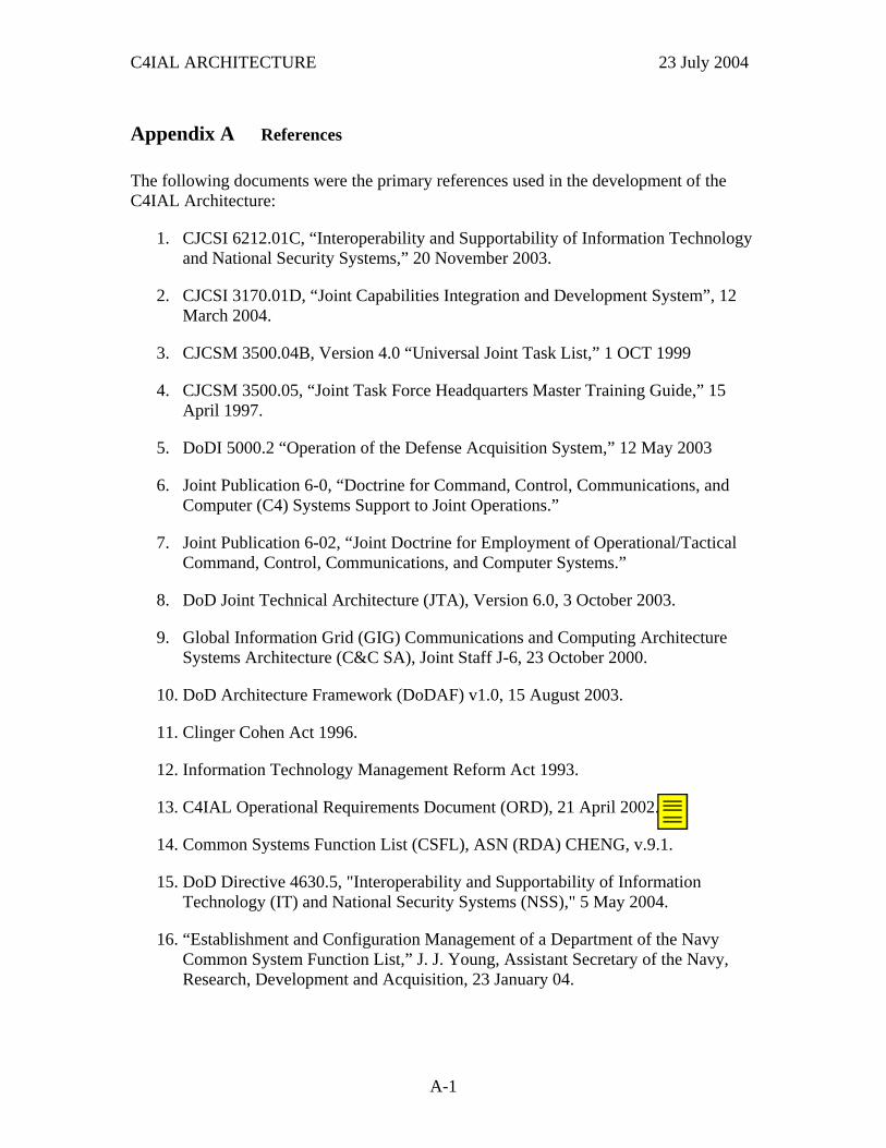
C4IAL ARCHITECTURE 23 July 2004
Appendix A References
The following documents were the primary references used in the development of the C4IAL Architecture:
1. CJCSI 6212.01C, “Interoperability and Supportability of Information Technology and National Security Systems,” 20 November 2003.
2. CJCSI 3170.01D, “Joint Capabilities Integration and Development System”, 12 March 2004.
3. CJCSM 3500.04B, Version 4.0 “Universal Joint Task List,” 1 OCT 1999
4. CJCSM 3500.05, “Joint Task Force Headquarters Master Training Guide,” 15 April 1997.
5. DoDI 5000.2 “Operation of the Defense Acquisition System,” 12 May 2003
6. Joint Publication 6-0, “Doctrine for Command, Control, Communications, and Computer (C4) Systems Support to Joint Operations.”
7. Joint Publication 6-02, “Joint Doctrine for Employment of Operational/Tactical Command, Control, Communications, and Computer Systems.”
8. DoD Joint Technical Architecture (JTA), Version 6.0, 3 October 2003.
9. Global Information Grid (GIG) Communications and Computing Architecture Systems Architecture (C&C SA), Joint Staff J-6, 23 October 2000.
10. DoD Architecture Framework (DoDAF) v1.0, 15 August 2003.
11. Clinger Cohen Act 1996.
12. Information Technology Management Reform Act 1993.
13. C4IAL Operational Requirements Document (ORD), 21 April 2002.
14. Common Systems Function List (CSFL), ASN (RDA) CHENG, v.9.1.
15. DoD Directive 4630.5, "Interoperability and Supportability of Information Technology (IT) and National Security Systems (NSS)," 5 May 2004.
16. “Establishment and Configuration Management of a Department of the Navy Common System Function List,” J. J. Young, Assistant Secretary of the Navy, Research, Development and Acquisition, 23 January 04.
A-1
deatond
Need correct date for the signed ORD.

C4IAL ARCHITECTURE 23 July 2004
This page intentionally left blank.
A-2
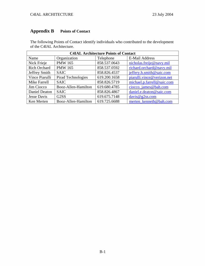
C4IAL ARCHITECTURE 23 July 2004
Appendix B Points of Contact
The following Points of Contact identify individuals who contributed to the development of the C4IAL Architecture.
C4IAL Architecture Points of Contact Name Organization Telephone E-Mail Address Nick Frieje PMW 165 858.537.0643 [email protected] Orchard PMW 165 858.537.0592 [email protected] Smith SAIC 858.826.4537 [email protected] Piarulli Pirad Technologies 619.200.1658 [email protected] Farrell SAIC 858.826.5719 [email protected] Ciocco Booz-Allen-Hamilton 619.680.4785 [email protected] Deaton SAIC 858.826.4867 [email protected] Davis G2SS 619.675.7148 [email protected] Merten Booz-Allen-Hamilton 619.725.6688 [email protected]
B-1

C4IAL ARCHITECTURE 23 July 2004
This page intentionally left blank.
B-2
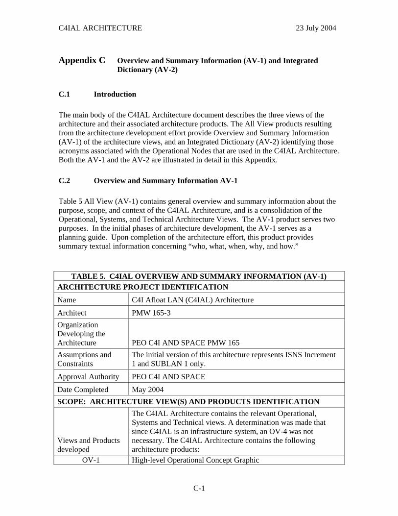
C4IAL ARCHITECTURE 23 July 2004
Appendix C Overview and Summary Information (AV-1) and Integrated Dictionary (AV-2)
C.1 Introduction
The main body of the C4IAL Architecture document describes the three views of the architecture and their associated architecture products. The All View products resulting from the architecture development effort provide Overview and Summary Information (AV-1) of the architecture views, and an Integrated Dictionary (AV-2) identifying those acronyms associated with the Operational Nodes that are used in the C4IAL Architecture. Both the AV-1 and the AV-2 are illustrated in detail in this Appendix.
C.2 Overview and Summary Information AV-1
Table 5 All View (AV-1) contains general overview and summary information about the purpose, scope, and context of the C4IAL Architecture, and is a consolidation of the Operational, Systems, and Technical Architecture Views. The AV-1 product serves two purposes. In the initial phases of architecture development, the AV-1 serves as a planning guide. Upon completion of the architecture effort, this product provides summary textual information concerning “who, what, when, why, and how.”
TABLE 5. C4IAL OVERVIEW AND SUMMARY INFORMATION (AV-1) ARCHITECTURE PROJECT IDENTIFICATION
Name C4I Afloat LAN (C4IAL) Architecture
Architect PMW 165-3 Organization Developing the Architecture PEO C4I AND SPACE PMW 165 Assumptions and Constraints
The initial version of this architecture represents ISNS Increment 1 and SUBLAN 1 only.
Approval Authority PEO C4I AND SPACE
Date Completed May 2004 SCOPE: ARCHITECTURE VIEW(S) AND PRODUCTS IDENTIFICATION
Views and Products developed
The C4IAL Architecture contains the relevant Operational, Systems and Technical views. A determination was made that since C4IAL is an infrastructure system, an OV-4 was not necessary. The C4IAL Architecture contains the following architecture products:
OV-1 High-level Operational Concept Graphic
C-1
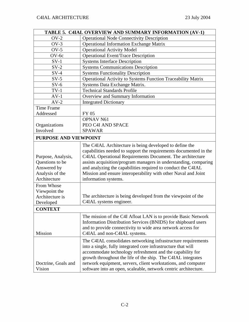
C4IAL ARCHITECTURE 23 July 2004
TABLE 5. C4IAL OVERVIEW AND SUMMARY INFORMATION (AV-1) OV-2 Operational Node Connectivity Description OV-3 Operational Information Exchange Matrix OV-5 Operational Activity Model OV-6c Operational Event/Trace Description SV-1 Systems Interface Description SV-2 Systems Communications Description SV-4 Systems Functionality Description SV-5 Operational Activity to Systems Function Traceability Matrix SV-6 Systems Data Exchange Matrix. TV-1 Technical Standards Profile AV-1 Overview and Summary Information AV-2 Integrated Dictionary
Time Frame Addressed FY 05
Organizations Involved
OPNAV N61 PEO C4I AND SPACE SPAWAR
PURPOSE AND VIEWPOINT
Purpose, Analysis, Questions to be Answered by Analysis of the Architecture
The C4IAL Architecture is being developed to define the capabilities needed to support the requirements documented in the C4IAL Operational Requirements Document. The architecture assists acquisition/program managers in understanding, comparing and analyzing the capabilities required to conduct the C4IAL Mission and ensure interoperability with other Naval and Joint information systems.
From Whose Viewpoint the Architecture is Developed
The architecture is being developed from the viewpoint of the C4IAL systems engineer.
CONTEXT
Mission
The mission of the C4I Afloat LAN is to provide Basic Network Information Distribution Services (BNIDS) for shipboard users and to provide connectivity to wide area network access for C4IAL and non-C4IAL systems.
Doctrine, Goals and Vision
The C4IAL consolidates networking infrastructure requirements into a single, fully integrated core infrastructure that will accommodate technology refreshment and the capability for growth throughout the life of the ship. The C4IAL integrates network equipment, servers, client workstations, and computer software into an open, scaleable, network centric architecture.
C-2
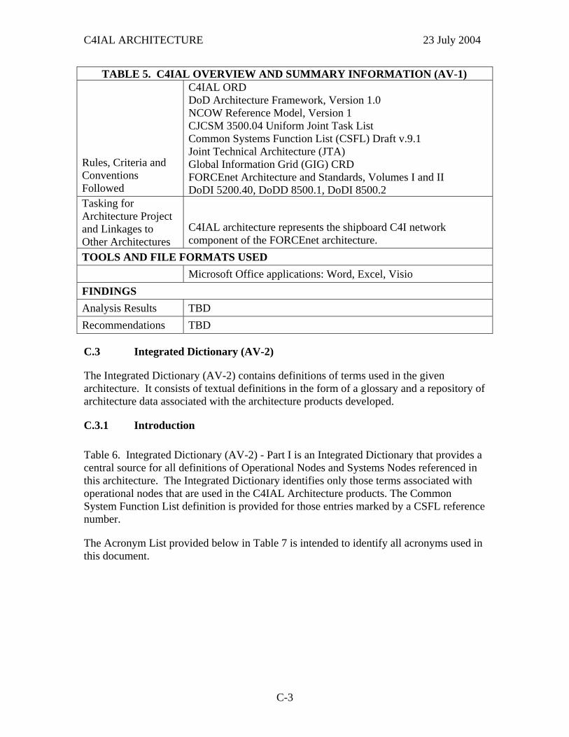
C4IAL ARCHITECTURE 23 July 2004
TABLE 5. C4IAL OVERVIEW AND SUMMARY INFORMATION (AV-1)
Rules, Criteria and Conventions Followed
C4IAL ORD DoD Architecture Framework, Version 1.0 NCOW Reference Model, Version 1 CJCSM 3500.04 Uniform Joint Task List Common Systems Function List (CSFL) Draft v.9.1 Joint Technical Architecture (JTA) Global Information Grid (GIG) CRD FORCEnet Architecture and Standards, Volumes I and II DoDI 5200.40, DoDD 8500.1, DoDI 8500.2
Tasking for Architecture Project and Linkages to Other Architectures
C4IAL architecture represents the shipboard C4I network component of the FORCEnet architecture.
TOOLS AND FILE FORMATS USED Microsoft Office applications: Word, Excel, Visio FINDINGS Analysis Results TBD Recommendations TBD
C.3 Integrated Dictionary (AV-2)
The Integrated Dictionary (AV-2) contains definitions of terms used in the given architecture. It consists of textual definitions in the form of a glossary and a repository of architecture data associated with the architecture products developed.
C.3.1 Introduction
Table 6. Integrated Dictionary (AV-2) - Part I is an Integrated Dictionary that provides a central source for all definitions of Operational Nodes and Systems Nodes referenced in this architecture. The Integrated Dictionary identifies only those terms associated with operational nodes that are used in the C4IAL Architecture products. The Common System Function List definition is provided for those entries marked by a CSFL reference number.
The Acronym List provided below in Table 7 is intended to identify all acronyms used in this document.
C-3

C4IAL ARCHITECTURE 23 July 2004
TABLE 6. INTEGRATED DICTIONARY (AV-2) - PART I Producers,
Receivers, System Functions &
Nodes
Identification
Access Control (CSFL 5.5.16) The limitation of access to information by authorized users only.
ADNS Automated Digital Network System – Serves as the off-ship communications gateway for C4IAL.
Authenticate User Access
(CSFL 5.4.4.1.8.7.1) Assure the identity of the person at the other end of the network. Automatically Generate and Display Network Status
(CSFL 5.4.4.1.8.1) Present an integrated/correlated presentation of networks and associated network assets.
Backup (CSFL 5.6.1) The storage of duplicative data. C4IAL user Authorized user of the network
Calendaring
(CSFL 4.2.2)
Schedule and view resources. Reduce the time needed to schedule meetings and identify and reserve required resources, including people, conference rooms, and equipment such as overhead Projectors.
Compress Data
(CSFL 5.4.2) Eliminate gaps, empty fields, redundancies, and unnecessary data to shorten length of data blocks prior to transfer.
Conduct Operational Mode (CSFL 5.5.4)
Maintain control of the operational mode of the information transport services for Normal, Battle short, and EMCON conditions.
Conduct Performance Management (CSFL 5.4.4.1.8.2)
Monitor, test, activate, deactivate, log, and report on circuit connections of all controllable network resources in order to determine operating level and make adjustments as necessary to improve performance. Manually enter, store, and display the status of non-controlled network assets.
Control Operation of Computer (CSFL 5.2)
Control the scheduling, allocation, and sequencing of computer system resources and operations.
Convert Documents (CSFL 4.3.1)
Convert/export documents, graphics to different formats. Used for security and portability.
Create, Produce and Convert Documents (CSFL 4.3) Manipulating styles, formats, file types.
C-4
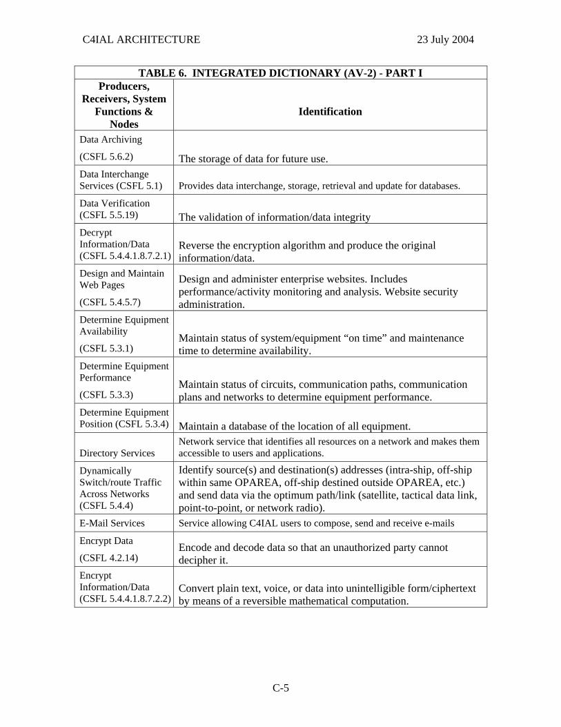
C4IAL ARCHITECTURE 23 July 2004
TABLE 6. INTEGRATED DICTIONARY (AV-2) - PART I Producers,
Receivers, System Functions &
Nodes
Identification
Data Archiving
(CSFL 5.6.2) The storage of data for future use. Data Interchange Services (CSFL 5.1) Provides data interchange, storage, retrieval and update for databases.
Data Verification (CSFL 5.5.19) The validation of information/data integrity Decrypt Information/Data (CSFL 5.4.4.1.8.7.2.1)
Reverse the encryption algorithm and produce the original information/data.
Design and Maintain Web Pages
(CSFL 5.4.5.7)
Design and administer enterprise websites. Includes performance/activity monitoring and analysis. Website security administration.
Determine Equipment Availability
(CSFL 5.3.1) Maintain status of system/equipment “on time” and maintenance time to determine availability.
Determine Equipment Performance
(CSFL 5.3.3) Maintain status of circuits, communication paths, communication plans and networks to determine equipment performance.
Determine Equipment Position (CSFL 5.3.4) Maintain a database of the location of all equipment.
Directory Services Network service that identifies all resources on a network and makes them accessible to users and applications.
Dynamically Switch/route Traffic Across Networks (CSFL 5.4.4)
Identify source(s) and destination(s) addresses (intra-ship, off-ship within same OPAREA, off-ship destined outside OPAREA, etc.) and send data via the optimum path/link (satellite, tactical data link, point-to-point, or network radio).
E-Mail Services Service allowing C4IAL users to compose, send and receive e-mails
Encrypt Data
(CSFL 4.2.14) Encode and decode data so that an unauthorized party cannot decipher it.
Encrypt Information/Data (CSFL 5.4.4.1.8.7.2.2)
Convert plain text, voice, or data into unintelligible form/ciphertext by means of a reversible mathematical computation.
C-5
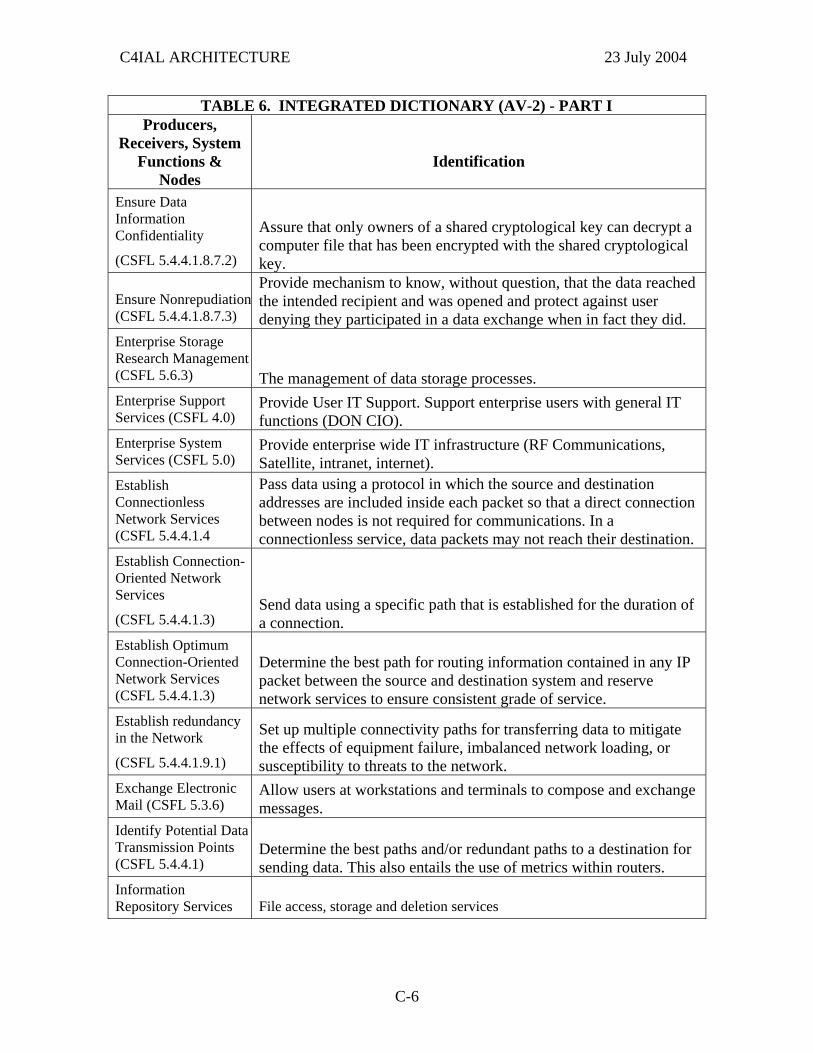
C4IAL ARCHITECTURE 23 July 2004
TABLE 6. INTEGRATED DICTIONARY (AV-2) - PART I Producers,
Receivers, System Functions &
Nodes
Identification
Ensure Data Information Confidentiality
(CSFL 5.4.4.1.8.7.2)
Assure that only owners of a shared cryptological key can decrypt a computer file that has been encrypted with the shared cryptological key.
Ensure Nonrepudiation(CSFL 5.4.4.1.8.7.3)
Provide mechanism to know, without question, that the data reached the intended recipient and was opened and protect against user denying they participated in a data exchange when in fact they did.
Enterprise Storage Research Management (CSFL 5.6.3) The management of data storage processes. Enterprise Support Services (CSFL 4.0)
Provide User IT Support. Support enterprise users with general IT functions (DON CIO).
Enterprise System Services (CSFL 5.0)
Provide enterprise wide IT infrastructure (RF Communications, Satellite, intranet, internet).
Establish Connectionless Network Services (CSFL 5.4.4.1.4
Pass data using a protocol in which the source and destination addresses are included inside each packet so that a direct connection between nodes is not required for communications. In a connectionless service, data packets may not reach their destination.
Establish Connection-Oriented Network Services
(CSFL 5.4.4.1.3) Send data using a specific path that is established for the duration of a connection.
Establish Optimum Connection-Oriented Network Services (CSFL 5.4.4.1.3)
Determine the best path for routing information contained in any IP packet between the source and destination system and reserve network services to ensure consistent grade of service.
Establish redundancy in the Network
(CSFL 5.4.4.1.9.1)
Set up multiple connectivity paths for transferring data to mitigate the effects of equipment failure, imbalanced network loading, or susceptibility to threats to the network.
Exchange Electronic Mail (CSFL 5.3.6)
Allow users at workstations and terminals to compose and exchange messages.
Identify Potential Data Transmission Points (CSFL 5.4.4.1)
Determine the best paths and/or redundant paths to a destination for sending data. This also entails the use of metrics within routers.
Information Repository Services File access, storage and deletion services
C-6

C4IAL ARCHITECTURE 23 July 2004
TABLE 6. INTEGRATED DICTIONARY (AV-2) - PART I Producers,
Receivers, System Functions &
Nodes
Identification
Interface with LAN/WAN
(CSFL 5.5.5)
Enable messages in the form of voice, video, and data to be distributed to and received from terminals/workstations in various shipboard/shore facility sites.
Limit Scope and Impact of Multi-cast Traffic
(CSFL 5.4.4.1.6)
Use protocols that allow a multicasting application to negotiate with routers, switches and clients to determine the devices that belong to a multicast group.
Maintain Address Book (CSFL 4.2.4.1) Maintain address book. Maintain Data File Integrity
(CSFL 5.4.4.1.8.7.4) Assure that a file was not changed or modified during processing and/or transit to the end user.
Maintain Journal (CSFL 4.2.4.2)
Provide a historical timeline record of project activities and events. Uses date stamping of, appointments, meetings, emails, completion dates.
Maintain Network-related Information (CSFL 5.4.4.1.7)
Cache the addresses of remote hosts and other information on advertised network services.
Manage and Manipulate File and File Systems
(CSFL 4.2.15) Browse, copy, delete, properties, synchronize, compare, etc. Manage Appointments (CSFL 4.2.2.1)
Manage events, seminars, meetings, and/or activities in a convenient calendar format.
Manage Network Operations
(CSFL 5.4.4.1.8) Utilize control signals as means to establish and terminate connections and maintain network operations.
Manage Security During Data Transmission
(CSFL 5.5.6)
Ensure information security measures are implemented, using encryption/decryption devices, keys, etc. to ensure protection of all traffic at the appropriate level.
Manually Configure/ reconfigure the Network
(CSFL 5.4.4.1.8.5.4)
Provide hardware and software required for network operators and managers to manually control radios, switches, and communications configurations.
C-7
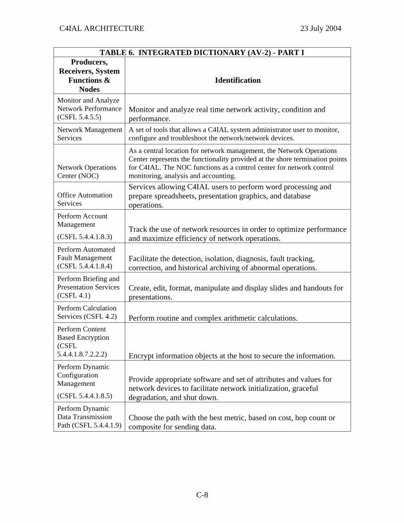
C4IAL ARCHITECTURE 23 July 2004
TABLE 6. INTEGRATED DICTIONARY (AV-2) - PART I Producers,
Receivers, System Functions &
Nodes
Identification
Monitor and Analyze Network Performance (CSFL 5.4.5.5)
Monitor and analyze real time network activity, condition and performance.
Network Management Services
A set of tools that allows a C4IAL system administrator user to monitor, configure and troubleshoot the network/network devices.
Network Operations Center (NOC)
As a central location for network management, the Network Operations Center represents the functionality provided at the shore termination points for C4IAL. The NOC functions as a control center for network control monitoring, analysis and accounting.
Office Automation Services
Services allowing C4IAL users to perform word processing and prepare spreadsheets, presentation graphics, and database operations.
Perform Account Management
(CSFL 5.4.4.1.8.3) Track the use of network resources in order to optimize performance and maximize efficiency of network operations.
Perform Automated Fault Management (CSFL 5.4.4.1.8.4)
Facilitate the detection, isolation, diagnosis, fault tracking, correction, and historical archiving of abnormal operations.
Perform Briefing and Presentation Services (CSFL 4.1)
Create, edit, format, manipulate and display slides and handouts for presentations.
Perform Calculation Services (CSFL 4.2)
Perform routine and complex arithmetic calculations.
Perform Content Based Encryption (CSFL 5.4.4.1.8.7.2.2.2) Encrypt information objects at the host to secure the information. Perform Dynamic Configuration Management
(CSFL 5.4.4.1.8.5)
Provide appropriate software and set of attributes and values for network devices to facilitate network initialization, graceful degradation, and shut down.
Perform Dynamic Data Transmission Path (CSFL 5.4.4.1.9)
Choose the path with the best metric, based on cost, hop count or composite for sending data.
C-8
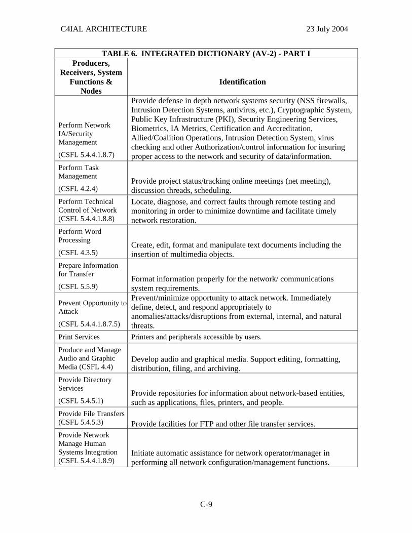
C4IAL ARCHITECTURE 23 July 2004
TABLE 6. INTEGRATED DICTIONARY (AV-2) - PART I Producers,
Receivers, System Functions &
Nodes
Identification
Perform Network IA/Security Management
(CSFL 5.4.4.1.8.7)
Provide defense in depth network systems security (NSS firewalls, Intrusion Detection Systems, antivirus, etc.), Cryptographic System, Public Key Infrastructure (PKI), Security Engineering Services, Biometrics, IA Metrics, Certification and Accreditation, Allied/Coalition Operations, Intrusion Detection System, virus checking and other Authorization/control information for insuring proper access to the network and security of data/information.
Perform Task Management
(CSFL 4.2.4) Provide project status/tracking online meetings (net meeting), discussion threads, scheduling.
Perform Technical Control of Network (CSFL 5.4.4.1.8.8)
Locate, diagnose, and correct faults through remote testing and monitoring in order to minimize downtime and facilitate timely network restoration.
Perform Word Processing
(CSFL 4.3.5) Create, edit, format and manipulate text documents including the insertion of multimedia objects.
Prepare Information for Transfer
(CSFL 5.5.9) Format information properly for the network/ communications system requirements.
Prevent Opportunity to Attack
(CSFL 5.4.4.1.8.7.5)
Prevent/minimize opportunity to attack network. Immediately define, detect, and respond appropriately to anomalies/attacks/disruptions from external, internal, and natural threats.
Print Services Printers and peripherals accessible by users.
Produce and Manage Audio and Graphic Media (CSFL 4.4)
Develop audio and graphical media. Support editing, formatting, distribution, filing, and archiving.
Provide Directory Services
(CSFL 5.4.5.1) Provide repositories for information about network-based entities, such as applications, files, printers, and people.
Provide File Transfers (CSFL 5.4.5.3) Provide facilities for FTP and other file transfer services. Provide Network Manage Human Systems Integration (CSFL 5.4.4.1.8.9)
Initiate automatic assistance for network operator/manager in performing all network configuration/management functions.
C-9
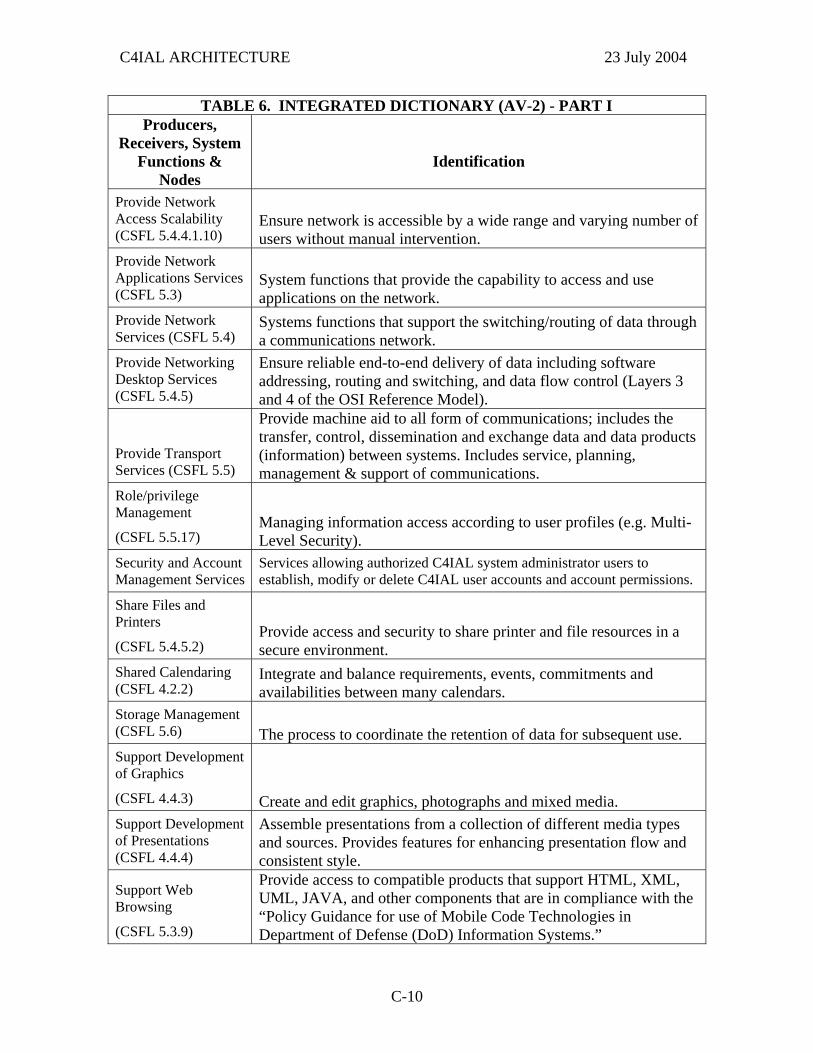
C4IAL ARCHITECTURE 23 July 2004
TABLE 6. INTEGRATED DICTIONARY (AV-2) - PART I Producers,
Receivers, System Functions &
Nodes
Identification
Provide Network Access Scalability (CSFL 5.4.4.1.10)
Ensure network is accessible by a wide range and varying number of users without manual intervention.
Provide Network Applications Services (CSFL 5.3)
System functions that provide the capability to access and use applications on the network.
Provide Network Services (CSFL 5.4)
Systems functions that support the switching/routing of data through a communications network.
Provide Networking Desktop Services (CSFL 5.4.5)
Ensure reliable end-to-end delivery of data including software addressing, routing and switching, and data flow control (Layers 3 and 4 of the OSI Reference Model).
Provide Transport Services (CSFL 5.5)
Provide machine aid to all form of communications; includes the transfer, control, dissemination and exchange data and data products (information) between systems. Includes service, planning, management & support of communications.
Role/privilege Management
(CSFL 5.5.17) Managing information access according to user profiles (e.g. Multi- Level Security).
Security and Account Management Services
Services allowing authorized C4IAL system administrator users to establish, modify or delete C4IAL user accounts and account permissions.
Share Files and Printers
(CSFL 5.4.5.2) Provide access and security to share printer and file resources in a secure environment.
Shared Calendaring (CSFL 4.2.2)
Integrate and balance requirements, events, commitments and availabilities between many calendars.
Storage Management (CSFL 5.6) The process to coordinate the retention of data for subsequent use. Support Development of Graphics
(CSFL 4.4.3) Create and edit graphics, photographs and mixed media. Support Development of Presentations (CSFL 4.4.4)
Assemble presentations from a collection of different media types and sources. Provides features for enhancing presentation flow and consistent style.
Support Web Browsing
(CSFL 5.3.9)
Provide access to compatible products that support HTML, XML, UML, JAVA, and other components that are in compliance with the “Policy Guidance for use of Mobile Code Technologies in Department of Defense (DoD) Information Systems.”
C-10
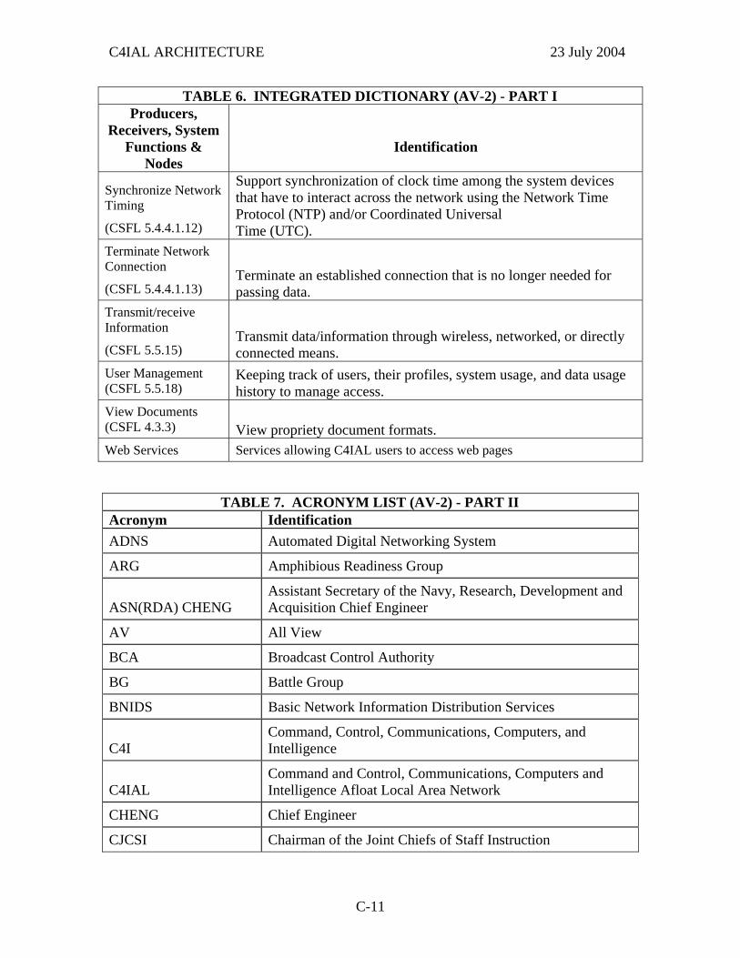
C4IAL ARCHITECTURE 23 July 2004
TABLE 6. INTEGRATED DICTIONARY (AV-2) - PART I Producers,
Receivers, System Functions &
Nodes
Identification
Synchronize Network Timing
(CSFL 5.4.4.1.12)
Support synchronization of clock time among the system devices that have to interact across the network using the Network Time Protocol (NTP) and/or Coordinated Universal Time (UTC).
Terminate Network Connection
(CSFL 5.4.4.1.13) Terminate an established connection that is no longer needed for passing data.
Transmit/receive Information
(CSFL 5.5.15) Transmit data/information through wireless, networked, or directly connected means.
User Management (CSFL 5.5.18)
Keeping track of users, their profiles, system usage, and data usage history to manage access.
View Documents (CSFL 4.3.3) View propriety document formats. Web Services Services allowing C4IAL users to access web pages
TABLE 7. ACRONYM LIST (AV-2) - PART II Acronym Identification ADNS Automated Digital Networking System
ARG Amphibious Readiness Group
ASN(RDA) CHENG Assistant Secretary of the Navy, Research, Development and Acquisition Chief Engineer
AV All View
BCA Broadcast Control Authority
BG Battle Group
BNIDS Basic Network Information Distribution Services
C4I Command, Control, Communications, Computers, and Intelligence
C4IAL Command and Control, Communications, Computers and Intelligence Afloat Local Area Network
CHENG Chief Engineer
CJCSI Chairman of the Joint Chiefs of Staff Instruction
C-11
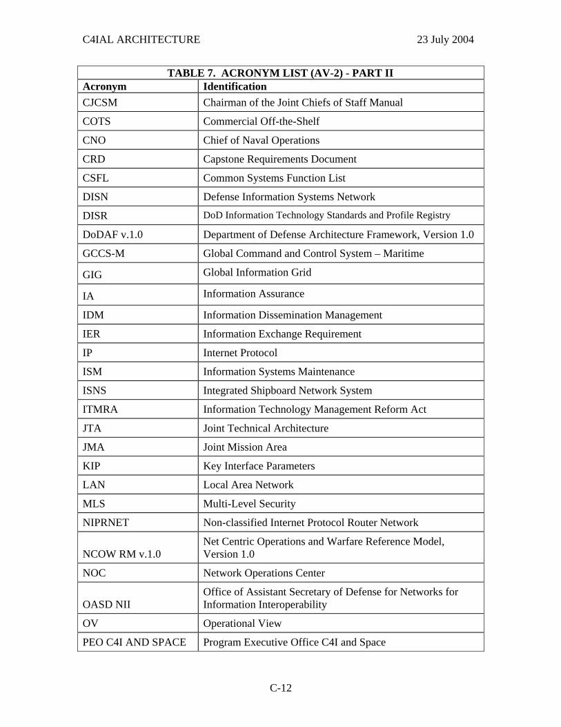
C4IAL ARCHITECTURE 23 July 2004
TABLE 7. ACRONYM LIST (AV-2) - PART II Acronym Identification CJCSM Chairman of the Joint Chiefs of Staff Manual
COTS Commercial Off-the-Shelf
CNO Chief of Naval Operations
CRD Capstone Requirements Document
CSFL Common Systems Function List
DISN Defense Information Systems Network
DISR DoD Information Technology Standards and Profile Registry
DoDAF v.1.0 Department of Defense Architecture Framework, Version 1.0
GCCS-M Global Command and Control System – Maritime
GIG Global Information Grid
IA Information Assurance
IDM Information Dissemination Management
IER Information Exchange Requirement
IP Internet Protocol
ISM Information Systems Maintenance
ISNS Integrated Shipboard Network System
ITMRA Information Technology Management Reform Act
JTA Joint Technical Architecture
JMA Joint Mission Area
KIP Key Interface Parameters
LAN Local Area Network
MLS Multi-Level Security
NIPRNET Non-classified Internet Protocol Router Network
NCOW RM v.1.0 Net Centric Operations and Warfare Reference Model, Version 1.0
NOC Network Operations Center
OASD NII Office of Assistant Secretary of Defense for Networks for Information Interoperability
OV Operational View
PEO C4I AND SPACE Program Executive Office C4I and Space
C-12
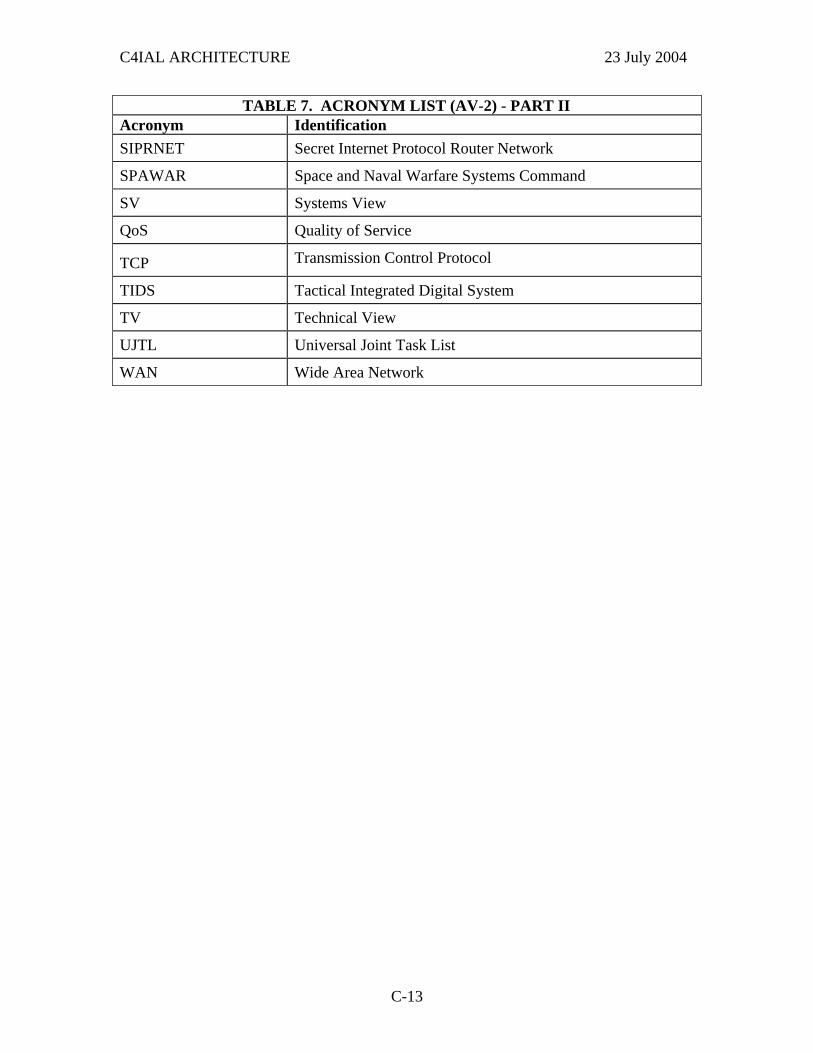
C4IAL ARCHITECTURE 23 July 2004
TABLE 7. ACRONYM LIST (AV-2) - PART II Acronym Identification SIPRNET Secret Internet Protocol Router Network
SPAWAR Space and Naval Warfare Systems Command
SV Systems View
QoS Quality of Service
TCP Transmission Control Protocol
TIDS Tactical Integrated Digital System
TV Technical View
UJTL Universal Joint Task List
WAN Wide Area Network
C-13

C4IAL ARCHITECTURE 23 July 2004
This page intentionally left blank.
C-14
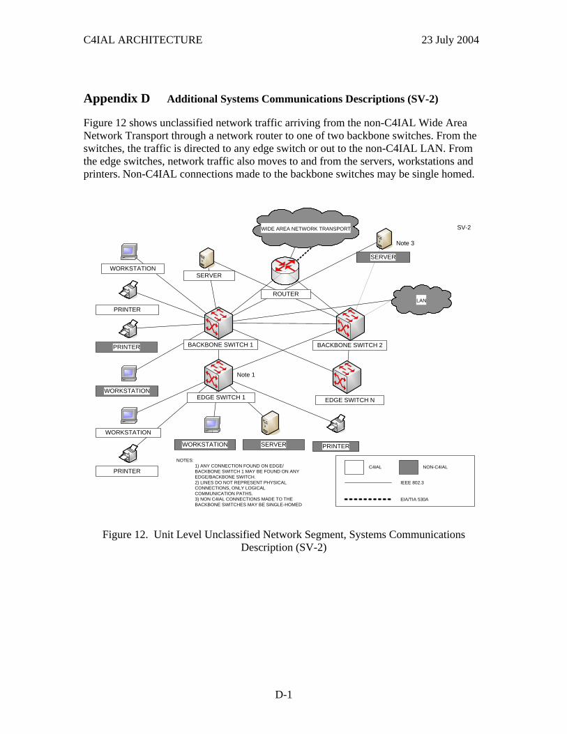
C4IAL ARCHITECTURE 23 July 2004
Appendix D Additional Systems Communications Descriptions (SV-2)
Figure 12 shows unclassified network traffic arriving from the non-C4IAL Wide Area Network Transport through a network router to one of two backbone switches. From the switches, the traffic is directed to any edge switch or out to the non-C4IAL LAN. From the edge switches, network traffic also moves to and from the servers, workstations and printers. Non-C4IAL connections made to the backbone switches may be single homed.
NOTES: 1) ANY CONNECTION FOUND ON EDGE/BACKBONE SWITCH 1 MAY BE FOUND ON ANY EDGE/BACKBONE SWITCH.2) LINES DO NOT REPRESENT PHYSICAL CONNECTIONS, ONLY LOGICAL COMMUNICATION PATHS. 3) NON C4IAL CONNECTIONS MADE TO THE BACKBONE SWITCHES MAY BE SINGLE-HOMED
SV-2
EIA/TIA 530A
IEEE 802.3
C4IAL NON-C4IAL
Note 3
Note 1
SERVER
WORKSTATION SERVER
PRINTER
PRINTER
PRINTER
PRINTER
WORKSTATIONEDGE SWITCH NEDGE SWITCH 1
BACKBONE SWITCH 2BACKBONE SWITCH 1
WORKSTATIONSERVER
ROUTER
WORKSTATION
LAN
WIDE AREA NETWORK TRANSPORT
Figure 12. Unit Level Unclassified Network Segment, Systems Communications Description (SV-2)
D-1

C4IAL ARCHITECTURE 23 July 2004
Figure 13 shows secret network traffic arriving from the non-C4IAL Wide Area Network Transport through a network router to one of two backbone switches. From the switches, the traffic is directed to servers, workstations, printers or out to the non-C4IAL LAN. Non-C4IAL connections made to the backbone switches may be single homed.
SV-2
SERVER
WORKSTATIONWORKSTATION
PRINTER
IEEE 802.3
NON-C4IAL
PRINTER
NOTES: 1) ANY CONNECTION FOUND ON BACKBONE SWITCH 1 MAY BE FOUND ON BACKBONE SWITCH2.2) LINES DO NOT REPRESENT PHYSICAL CONNECTIONS, ONLY LOGICAL COMMUNICATION PATHS. 3) NON C4IAL CONNECTIONS MADE TO THE BACKBONE SWITCHES MAYBE SINGLE HOMED
BACKBONE SWITCH 1 BACKBONE SWITCH 2
C4IAL
ROUTER
Note 1
Note 3
SERVER
LAN
WIDE AREA NETWORK TRANSPORT
Figure 13. Unit Level Secret Network Segment, Systems Communications Description (SV-2)
D-2
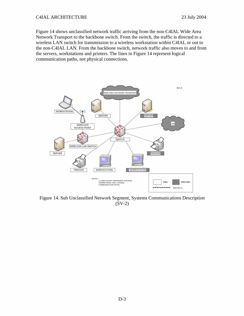
C4IAL ARCHITECTURE 23 July 2004
Figure 14 shows unclassified network traffic arriving from the non-C4IAL Wide Area Network Transport to the backbone switch. From the switch, the traffic is directed to a wireless LAN switch for transmission to a wireless workstation within C4IAL or out to the non-C4IAL LAN. From the backbone switch, network traffic also moves to and from the servers, workstations and printers. The lines in Figure 14 represent logical communication paths, not physical connections.
SV-2
WORKSTATIONPRINTER
SERVER
SERVER
WORKSTATION
PRINTER
IEEE 802.11
NON-C4IAL
NOTES: 1) LINES DO NOT REPRESENT PHYSICAL CONNECTIONS, ONLY LOGICAL COMMUNICATION PATHS.
SWITCH
SERVER
WIRELESS ACCESS POINT
WORKSTATION
WIRELESS LAN SWITCH
C4IAL
LAN
WIDE AREA NETWORK TRANSPORT
Figure 14. Sub Unclassified Network Segment, Systems Communications Description
(SV-2)
D-3
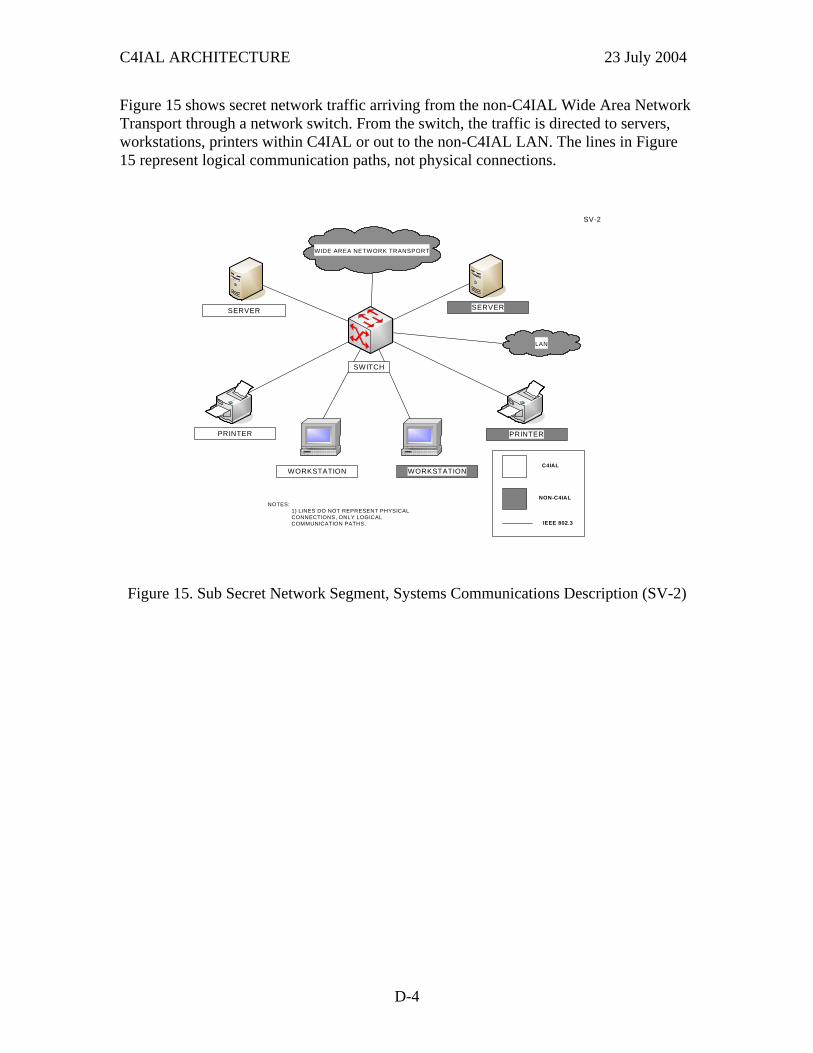
C4IAL ARCHITECTURE 23 July 2004
Figure 15 shows secret network traffic arriving from the non-C4IAL Wide Area Network Transport through a network switch. From the switch, the traffic is directed to servers, workstations, printers within C4IAL or out to the non-C4IAL LAN. The lines in Figure 15 represent logical communication paths, not physical connections. SV-2
SERVER
WORKSTATION
PRINTER
SERVER
WORKSTATION
PRINTER
NOTES: 1) LINES DO NOT REPRESENT PHYSICAL CONNECTIONS, ONLY LOGICAL COMMUNICATION PATHS.
SWITCH
C4IAL
NON-C4IAL
IEEE 802.3
WIDE AREA NETWORK TRANSPORT
LAN
Figure 15. Sub Secret Network Segment, Systems Communications Description (SV-2)
D-4