

C3D SURVEY DATABASE GROUPS-SURFACES-ALIGNMENTS · CIVIL 3D SURVEY DATABASE Open C3D –You DO NOT...
81
C3D SURVEY DATABASE GROUPS-SURFACES-ALIGNMENTS POINT AND FIGURE GROUPING SURFACE OBJECTS ALIGNMENT OBJECTS
Transcript of C3D SURVEY DATABASE GROUPS-SURFACES-ALIGNMENTS · CIVIL 3D SURVEY DATABASE Open C3D –You DO NOT...

C3D SURVEY DATABASEGROUPS-SURFACES-ALIGNMENTS
POINT AND FIGURE GROUPING
SURFACE OBJECTS
ALIGNMENT OBJECTS
FDOT2014.C3D
FDOT2014.C3D is the current State Kit for use with FDOT Civil 3D Projects. It is absolutely necessary for developing FDOT Deliverables.
Contains Software Applications, Tools, Resource Files, Fonts, Templates & Much More.
Don’t attempt to develop FDOT deliveries without it.
Download and install the FDOT2014 Software after installing Autodesk Civil 3D.
http://www.dot.state.fl.us/ecso/downloads/software/FDOT2014CADDSoftware.shtm

FDOT2014.C3D
For FDOT projects, AutoCAD Drawing Units Insertion scale should be set to “Unitless”
If the Insertion scale is set to feet, it is an international foot setting. 1 yard = 0.9144 meters, exactly.
FDOT works in Survey feet. 1 foot = 1200/3937 meters, exactly.
By setting the Insertion scale to “Unitless” the State Plane Projection will control the units.
All FDOT Templates are preset to “Unitless”
FDOT2014.C3D
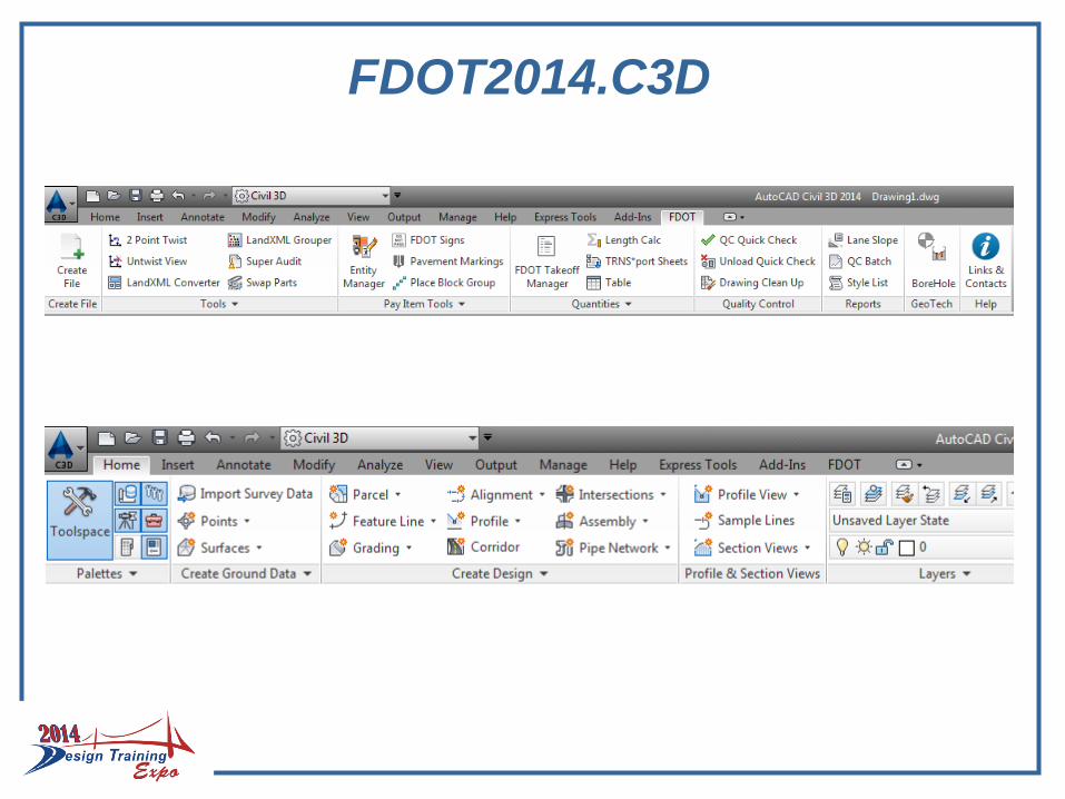
THE FDOT RIBBON
If not loaded type in the command “FDOTRIBBON”
Can be found on the ribbon bar, select the FDOT tab
Contains useful tools
For Survey look for:
- Create File
- LandXMLGrouper
- QC Quick Check
- Links & Contacts
FDOT2014.C3D
Open “Toolspace”
Toolspace is a palette found on the “Home” tab in the Civil 3D Ribbon.
For surveying projects it is recommended that the user activates:
- Prospector (Opens a tab in Toolspace)
- Settings (Opens a tab in Toolspace)
- Survey (Opens a tab in Toolspace)
- Toolbox (Opens a tab in Toolspace)
- Properties (Opens a separate palette that can be docked for continual use)
FDOT2014.C3D
CIVIL 3D SURVEY DATABASE
Separate from the DWG file
Yet is dynamically linked to the active drawing file
Consist of two files
Survey.sdbx
Survey.SDXX
Can be edited directly
Can be edited through point and chain manipulation in the active drawing file.

CIVIL 3D SURVEY DATABASE
Open C3D – You DO NOT need to be in a specific drawing file to create
TOOLSPACE – Survey Tab
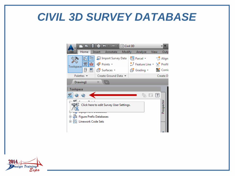
Set State Plane Zone in “Survey User Settings”
If the survey database fails to create and crashes then Civil 3D 2014 SP1 needs to be installed: Instead of setting the zone, choose “FDOT2014_DatabaseSettings.
- The zone can be set after the database is created by right clicking on the database and choosing “Edit Survey Database Settings…”
CIVIL 3D SURVEY DATABASE

CIVIL 3D SURVEY DATABASE
Set working folder…
FDOT recommends that your working folder is the survey folder in the project directory structure
If the database is shown in Toolspace but not highlighted like below it exist but is not open for use or editing.
CIVIL 3D SURVEY DATABASE
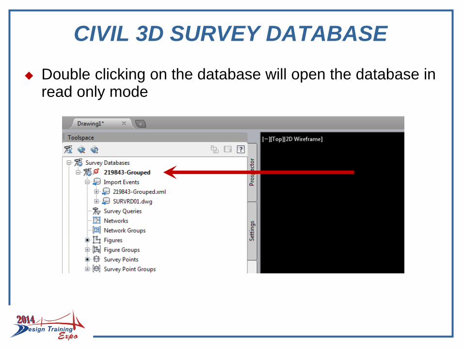
Double clicking on the database will open the database in read only mode
CIVIL 3D SURVEY DATABASE
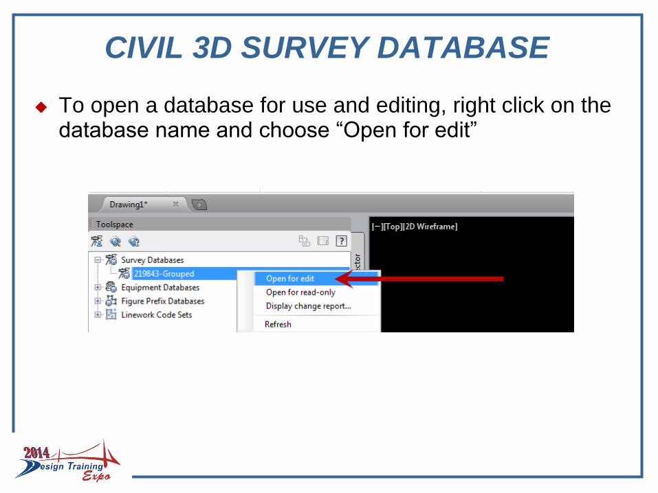
To open a database for use and editing, right click on the database name and choose “Open for edit”
CIVIL 3D SURVEY DATABASE
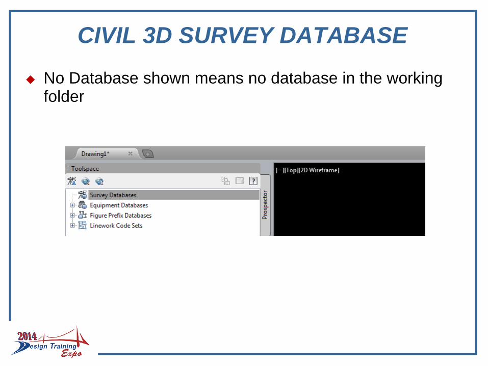
No Database shown means no database in the working folder

CIVIL 3D SURVEY DATABASE
To create a database, right click “Survey Databases” and select “New local survey database…”
Give the database a name
CIVIL 3D SURVEY DATABASE
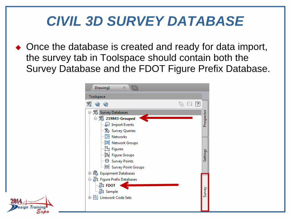
Once the database is created and ready for data import, the survey tab in Toolspace should contain both the Survey Database and the FDOT Figure Prefix Database.

CIVIL 3D SURVEY DATABASE
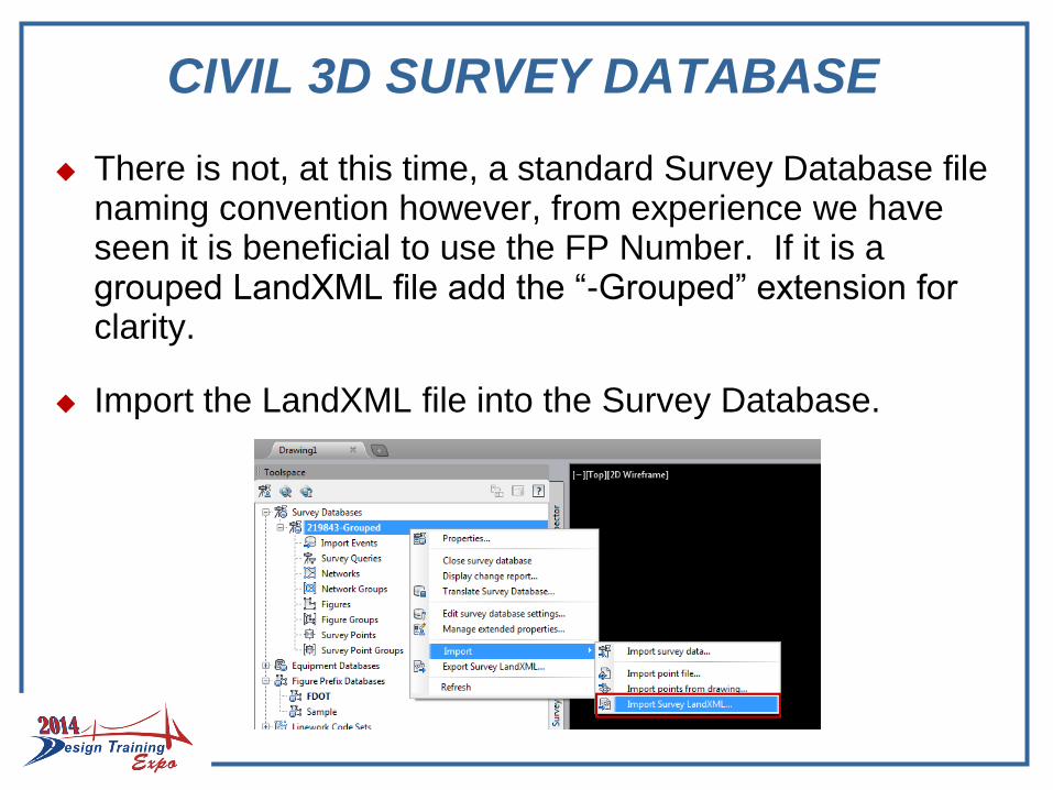
To populate the survey database with an XML file from CAiCE or EFB, right click on the Survey Database name and select Import and choose “Import survey data...” (import wizard) or “Import Survey LandXML…”
CIVIL 3D SURVEY DATABASE
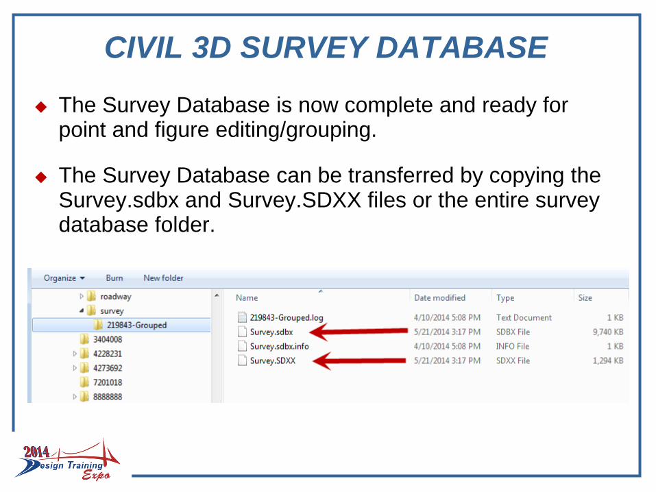
The Survey Database is now complete and ready for point and figure editing/grouping.
The Survey Database can be transferred by copying the Survey.sdbx and Survey.SDXX files or the entire survey database folder.
POINT AND FIGURE GROUPS
Point and Figures can be grouped within the survey database.
Point and Figure Groups are necessary for the efficient analysis, editing and visualization of survey data.
Groups can be created manually within the survey database.
Groups can be created in the XML prior to import into the survey database.
The LandXML Grouper tool on the FDOT ribbon can be used to group XML data prior to import
POINT AND FIGURE GROUPS
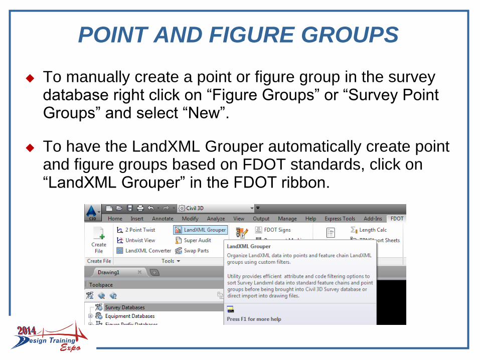
To manually create a point or figure group in the survey database right click on “Figure Groups” or “Survey Point Groups” and select “New”.
To have the LandXML Grouper automatically create point and figure groups based on FDOT standards, click on “LandXML Grouper” in the FDOT ribbon.
LANDXML GROUPER
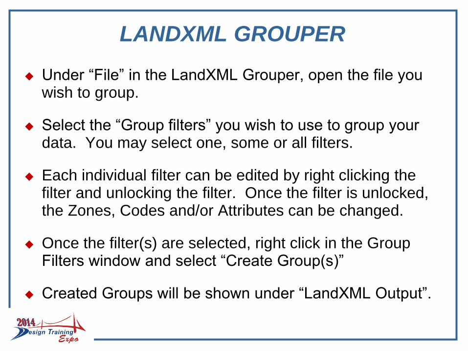
Under “File” in the LandXML Grouper, open the file you wish to group.
Select the “Group filters” you wish to use to group your data. You may select one, some or all filters.
Each individual filter can be edited by right clicking the filter and unlocking the filter. Once the filter is unlocked, the Zones, Codes and/or Attributes can be changed.
Once the filter(s) are selected, right click in the Group Filters window and select “Create Group(s)”
Created Groups will be shown under “LandXML Output”.

LANDXML GROUPER

LANDXML GROUPER
All groups were selected and all groups were created below. Individual groups can be viewed and edited before export to a grouped LandXML file.
LANDXML GROUPER
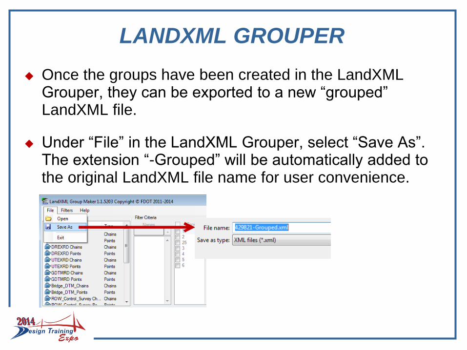
Once the groups have been created in the LandXML Grouper, they can be exported to a new “grouped” LandXML file.
Under “File” in the LandXML Grouper, select “Save As”. The extension “-Grouped” will be automatically added to the original LandXML file name for user convenience.
LANDXML GROUPER
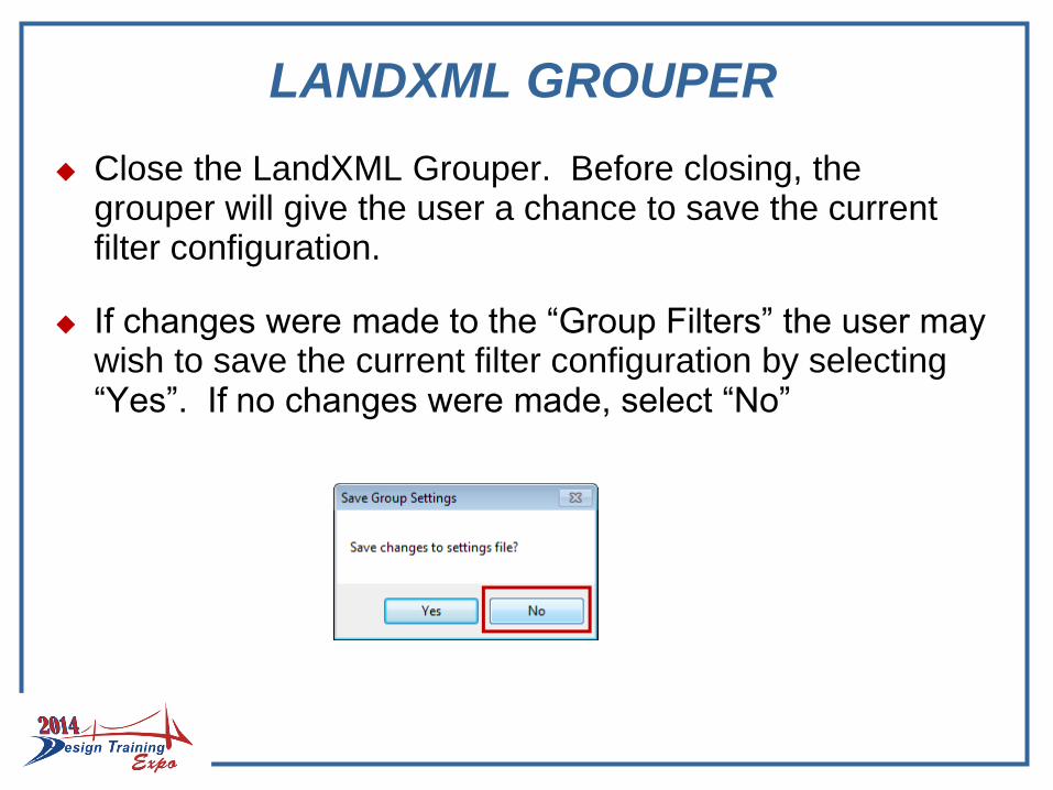
Close the LandXML Grouper. Before closing, the grouper will give the user a chance to save the current filter configuration.
If changes were made to the “Group Filters” the user may wish to save the current filter configuration by selecting “Yes”. If no changes were made, select “No”
CIVIL 3D SURVEY DATABASE
There is not, at this time, a standard Survey Database file naming convention however, from experience we have seen it is beneficial to use the FP Number. If it is a grouped LandXML file add the “-Grouped” extension for clarity.
Import the LandXML file into the Survey Database.

CIVIL 3D SURVEY DATABASE
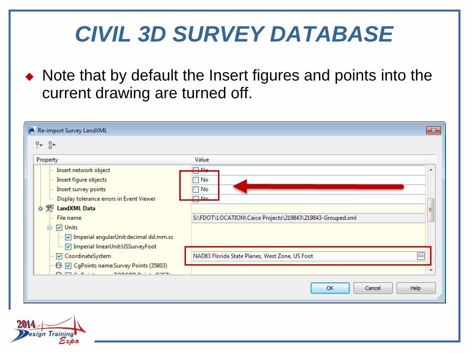
The Import Survey LandXML dialogue box will open. Select the appropriate Datum/Projection and press “OK”.
CIVIL 3D SURVEY DATABASE
Note that by default the Insert figures and points into the current drawing are turned off.
CIVIL 3D POINT & FIGURE GROUPS
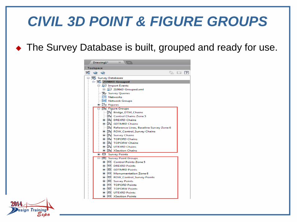
The Survey Database is built, grouped and ready for use.
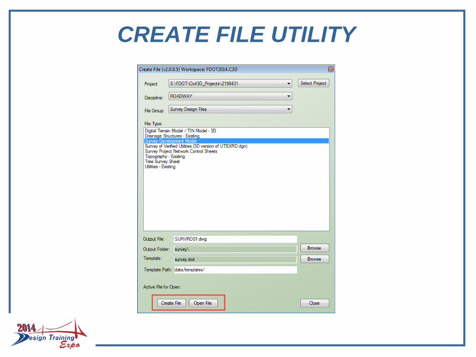
CREATE FILE UTILITY
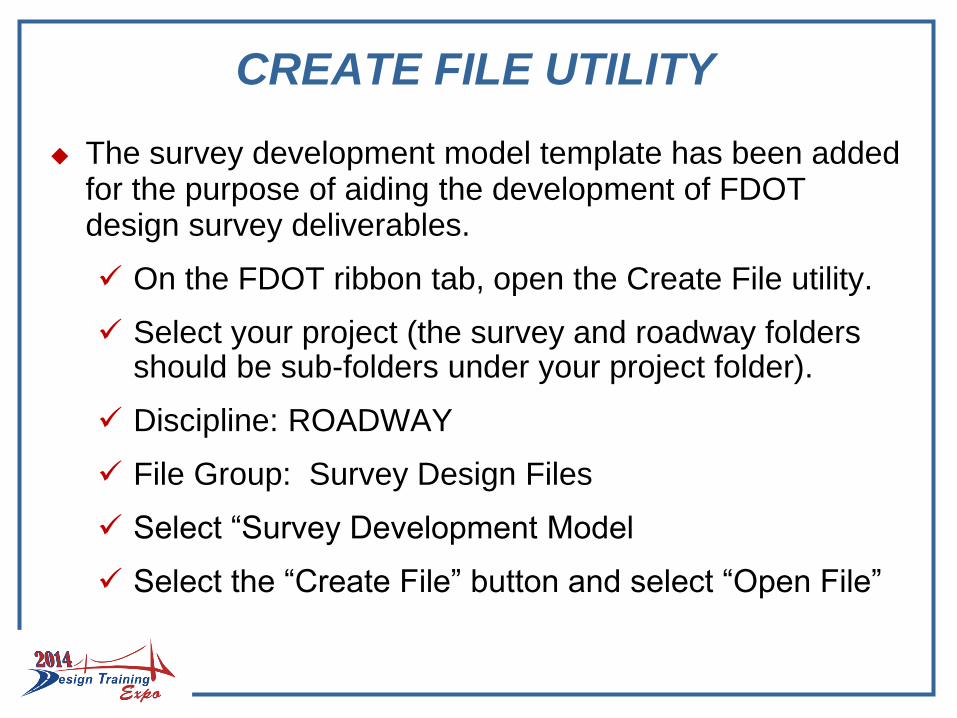
The survey development model template has been added for the purpose of aiding the development of FDOT design survey deliverables.
On the FDOT ribbon tab, open the Create File utility.
Select your project (the survey and roadway folders should be sub-folders under your project folder).
Discipline: ROADWAY
File Group: Survey Design Files
Select “Survey Development Model
Select the “Create File” button and select “Open File”

CREATE FILE UTILITY
Note that the base file for all surveying design files can be created from the “Survey Design Files” file group.
The Output File uses the associated template and adds a two digit number starting with 01 and increments automatically as files from a given template are created.
The Template used and the Template Path are also shown in the Create File utility.
Once a file is created and opened the Create File utility can be closed.
Note: The Alignment is under “Roadway Design Files”.
CREATE FILE UTILITY
Set The Projection (State Plane)
FDOT templates do not have the State Plane Zone preset due to most districts and consultants working in multiple zones. Therefore once a survey design file has been created the first thing that should be done is to set the appropriate State Plane Zone.
There are multiple ways to set the State Plane Zone.
In the Toolspace>Settings tab right click on the file name and select “Edit Drawing Settings…”
- Manually select the Zone from the Units and Zone tab “No Datum, No Projection” pull down
- Or manually type in the coordinate system code.

Set The Projection (State Plane)
FDOT has provided another Way to set the Florida State Plane zone, US Foot.
Type in the Civil 3D command line:
- SETFLNORTH
- SETFLWEST
- SETFLEAST
Select the “Yes” button on the Change Coordinate System warning dialogue box and SAVE your drawing
SURFACES
Surfaces are Civil 3D objects
A Civil 3D object has imbedded intelligence.
Surfaces are created and saved within a specific drawing. They are not part of the Survey Database, but they can be dynamically linked.
The SURVRD template was constructed for building surfaces.
Surfaces can be exported as a Surface LandXML file.
Surface LandXML files should be imported into the GDTMRD.dwg file for delivery to design

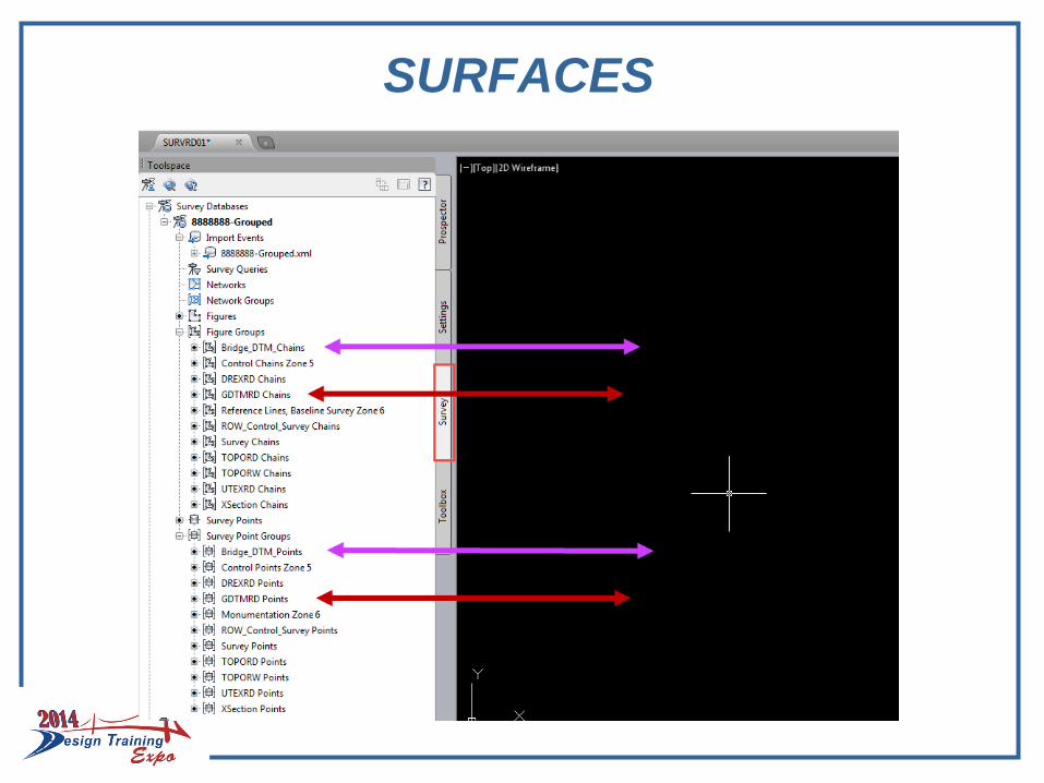
SURFACES
Surfaces in Civil 3D are created from survey points and figures inserted into the drawing file. Therefore surfaces depend on the visualization of points and chains.
The GDTMRD Point and Chain groups created by the LandXML grouper are specifically points and chains in zone one and/or zone two that have a “ground” attribute
The Bridge_DTM_Points and the Bridge_DTM_Chainsare groups created by the LandXML grouper that are in zone four and have a “ground” attribute.
Therefore if the survey points and chains in a project use the current standards, these groups can be used to create ground and bridge surfaces.
SURFACES

SURFACES
In Toolspace>Prospector, right click on surfaces and create a new existing ground surface.
SURFACES
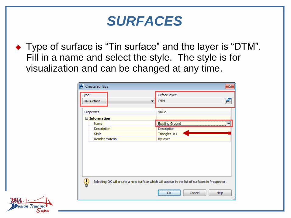
Type of surface is “Tin surface” and the layer is “DTM”. Fill in a name and select the style. The style is for visualization and can be changed at any time.
ADD POINTS TO SURFACES
In the Toolspace>Prospector tab, expand surfaces to view the new surface and other facets of a Civil 3D surface.
The GDTMRD Point group will need to be added along with the GDTMRD Figure group for breaklines
In the Toolspace>Survey tab, right click on the GDTMRD Points group and “Insert into drawing”. This will add the GDTMRD Point group to Point Groups under the prospector tab.
Right click on the Prospector Point Groups and “Update”
ADD POINTS TO SURFACES
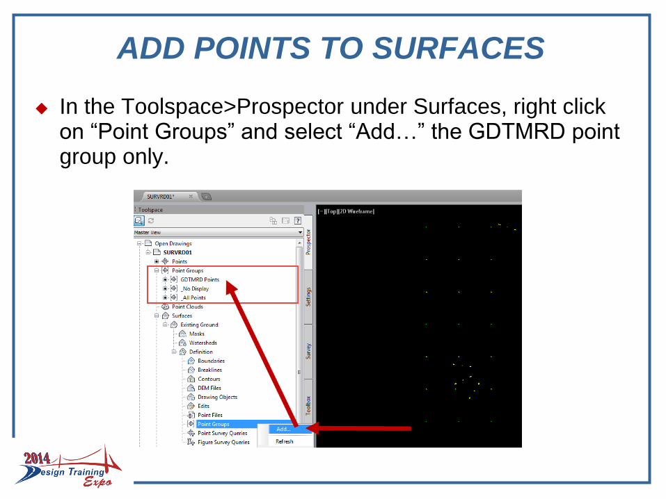
In the Toolspace>Prospector under Surfaces, right click on “Point Groups” and select “Add…” the GDTMRD point group only.

ADD POINTS TO SURFACES
A black dot is beside the Existing Ground - Point Groups. Civil 3D creates the surface and visualizes the currently selected style (Triangles).
ADD FIGURES TO SURFACES
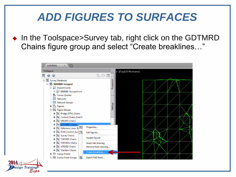
In the Toolspace>Survey tab, right click on the GDTMRD Chains figure group and select “Create breaklines…”
ADD FIGURES TO SURFACES
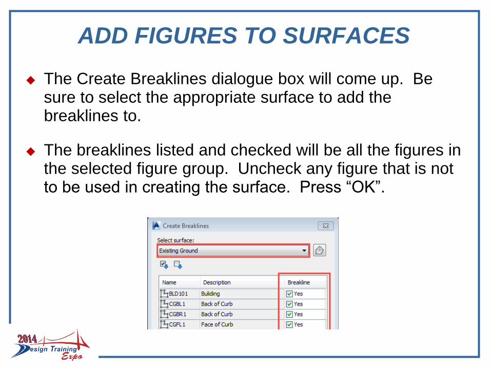
The Create Breaklines dialogue box will come up. Be sure to select the appropriate surface to add the breaklines to.
The breaklines listed and checked will be all the figures in the selected figure group. Uncheck any figure that is not to be used in creating the surface. Press “OK”.

ADD FIGURES TO SURFACES
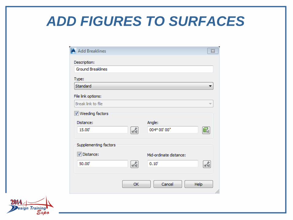
The Add Breaklines dialogue box will appear. Fill in the Description
The type breakline will generally be “Standard” however, Civil 3D has added some other types that can be used if needed.
Check the “Weeding factors” and the “Distance:” check boxes. Both have preset values that are generally standard but can be modified if need be.
Press “OK”
ADD FIGURES TO SURFACES
ADD FIGURES TO SURFACES
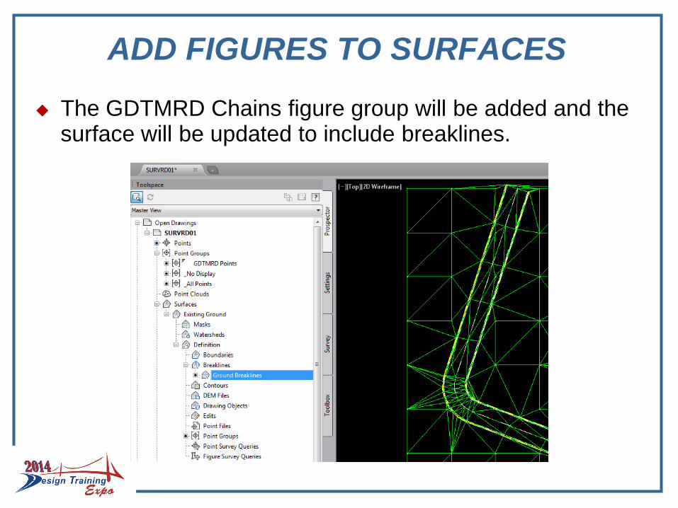
The GDTMRD Chains figure group will be added and the surface will be updated to include breaklines.
ADD FIGURES TO SURFACES
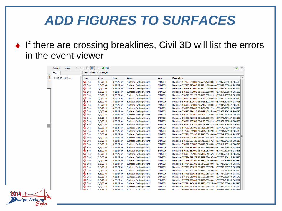
If there are crossing breaklines, Civil 3D will list the errors in the event viewer

RESOLVE CROSSING BREAKLINES
The “Resolve Crossing Breaklines” tool provided by Civil 3D will help with identifying crossing breaklines.
Breaklines can be resolved before the surface is created by inserting the breaklines into the drawing and running the “Resolve Crossing Breaklines” tool from the Civil 3D Ribbon under the Analyze tab - Ground Data drop down
Breaklines can be resolved after the surface is created by running the “Resolve Crossing Breaklines” from the contextual ribbon tab when the surface is selected.
To identify specific crossing breaklines, choose the Figure option to list in the event viewer.

RESOLVE CROSSING BREAKLINES
The event viewer will open with a “Crossing Breaklines” tab. Selecting the breakline in the event viewer will highlight both crossing breaklines, on screen (red & blue).

EDITING CROSSING BREAKLINES
Crossing breaklines must be manually edited to resolve. Since breaklines are “Figures” (chains), use the figure editor to edit breaklines.
Select a figure to edit. A contextual ribbon will open. Select “Survey Figure Properties” to edit the figure.
Civil 3D provides a group of tools just above the points list in the Figure Properties dialogue box to manipulate figures.
EDITING CROSSING BREAKLINES
When a figure is edited in the Figure Properties dialogue box, press “Apply” or “OK” to save these edits in the survey database.
NOTE: If a figure needs to be broken into two parts, a new figure name must be given to the remainder. This new chain is added to the survey database but it is NOT automatically part of the figure group. To add this chain to a figure group, right click on the appropriate figure group in the survey database, select properties, find the new chain name and select the check box.
If figure breaklines for an active surface are edited, In the Prospector, right click on the surface name and rebuild.
WORKING WITH SURFACES
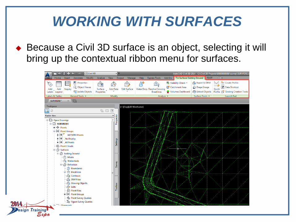
Because a Civil 3D surface is an object, selecting it will bring up the contextual ribbon menu for surfaces.

WORKING WITH SURFACES
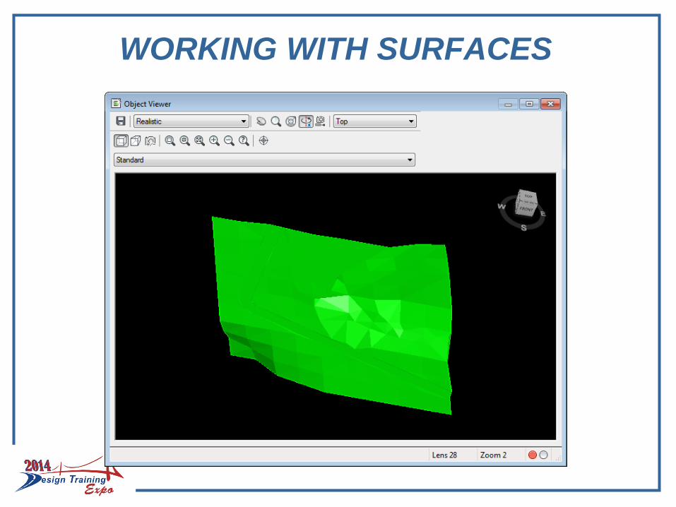
Selecting the “Object Viewer” will allow rotating and inspection of the surface with multiple renderings.
WORKING WITH SURFACES
WORKING WITH SURFACES
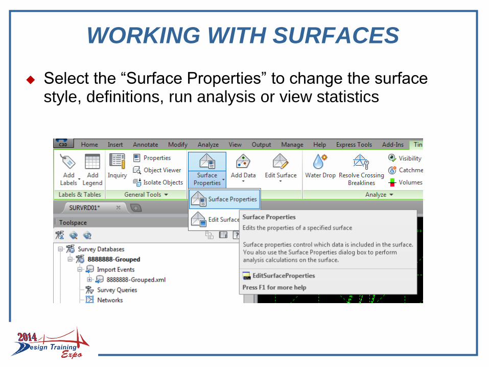
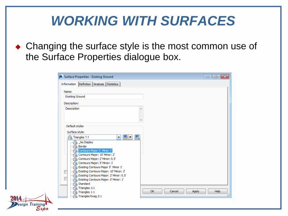
Select the “Surface Properties” to change the surface style, definitions, run analysis or view statistics
WORKING WITH SURFACES
Changing the surface style is the most common use of the Surface Properties dialogue box.
WORKING WITH SURFACES
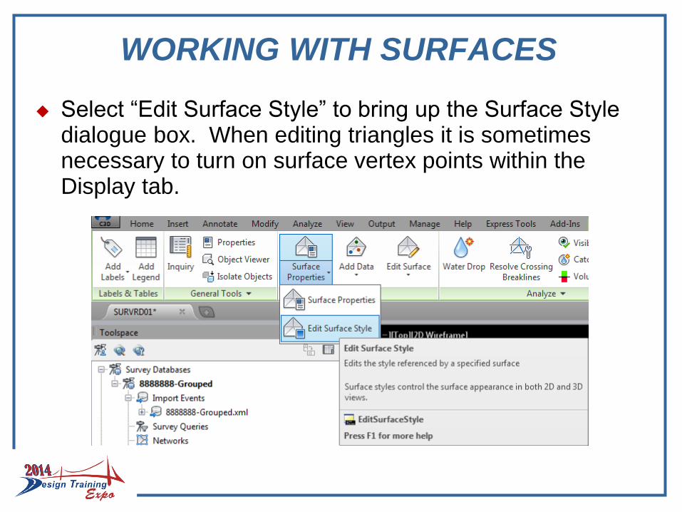
Select “Edit Surface Style” to bring up the Surface Style dialogue box. When editing triangles it is sometimes necessary to turn on surface vertex points within the Display tab.
WORKING WITH SURFACES
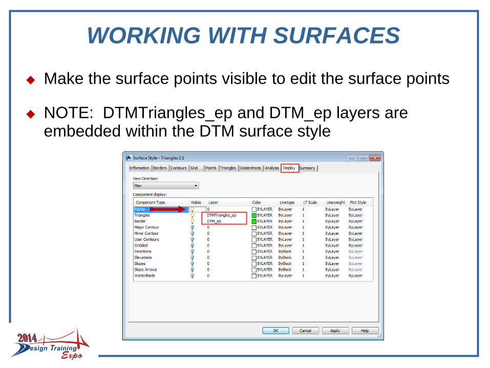
Make the surface points visible to edit the surface points
NOTE: DTMTriangles_ep and DTM_ep layers are embedded within the DTM surface style

WORKING WITH SURFACES
When surface points are turned on a blue plus sign will appear at each surface vertex.
WORKING WITH SURFACES
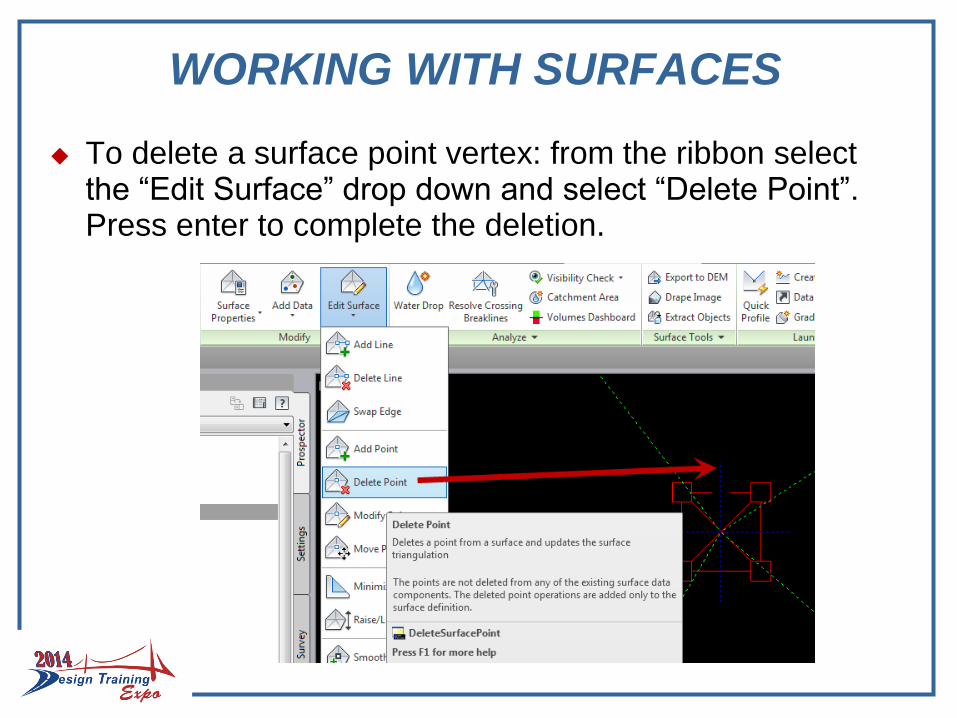
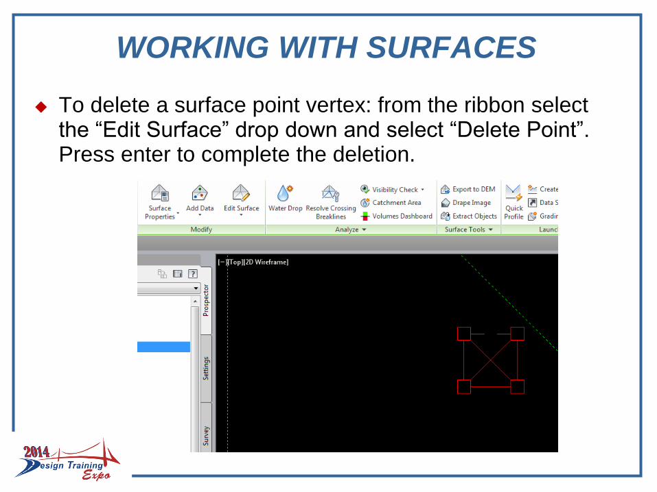
To delete a surface point vertex: from the ribbon select the “Edit Surface” drop down and select “Delete Point”. Press enter to complete the deletion.
WORKING WITH SURFACES
To delete a surface point vertex: from the ribbon select the “Edit Surface” drop down and select “Delete Point”. Press enter to complete the deletion.
WORKING WITH SURFACES
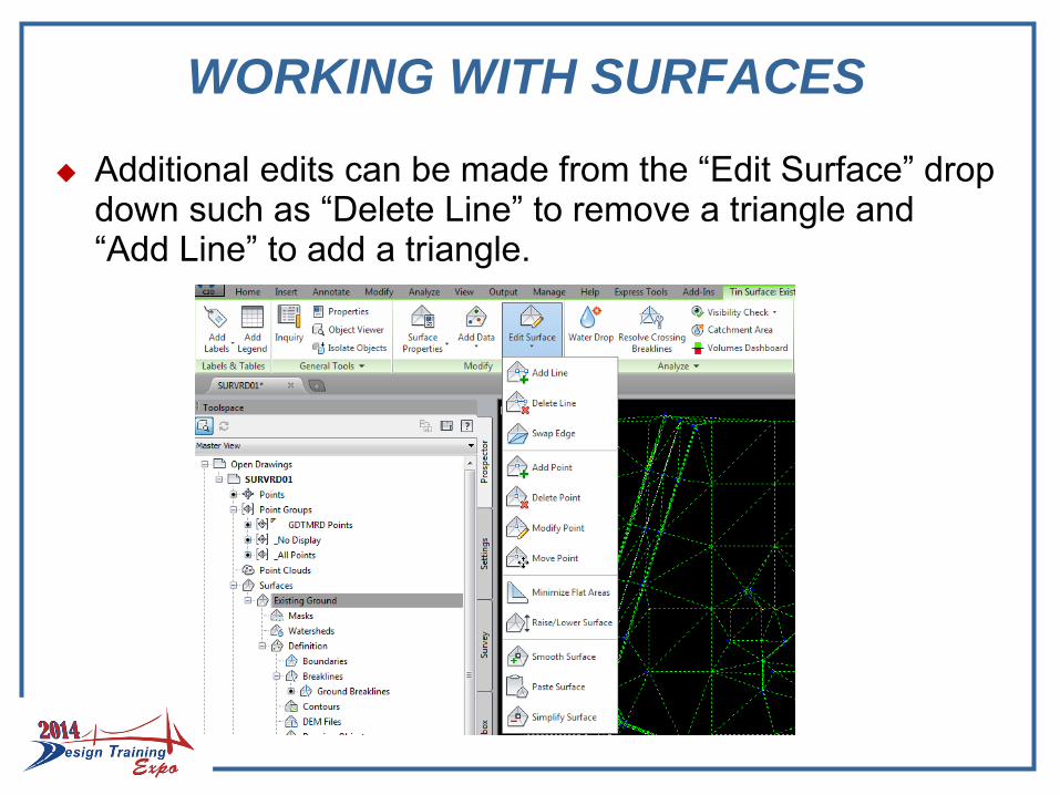
Additional edits can be made from the “Edit Surface” drop down such as “Delete Line” to remove a triangle and “Add Line” to add a triangle.

EXPORT SURFACE LANDXML
When a surface has been completed, in the Prospector, right click on the surface name and select “Export LandXML”
The “Export to LandXML” dialogue box will open and Surfaces and the surface name will already be checked.Press “OK”.
Save the Surface LandXML in the project survey folder for later use.
Note that any subsequent change to the points or figures on screen will affect the surface. Right click on the surface name and select “Lock” to prevent changes.
WORKING WITH SURFACES
Additional surfaces can be created in the SURVRD file, such as a bridge surface, following the same process.
Remember any visual change, even turning layers on and off will affect the surface.
Lock the surfaces to prevent change
To turn off the surface (un-visualize) select the surface or right click on the surface name and bring up the “Surface Properties” dialogue box. A surface style “_No Display” has been provided to hide the surface.
The “Export to LandXML” dialogue box will open and
ALIGNMENTS
Alignments are Civil 3D objects
A Civil 3D object has imbedded intelligence.
Alignments are created and saved within a specific drawing. They are not part of the Survey Database, but they can be dynamically linked.
The SURVRD template was specifically constructed for building alignments.
Alignments can be exported as a LandXML file.
Alignments LandXML files should be imported into the ALGNRD.dwg file for delivery to design

ALIGNMENTS FROM OBJECTS
Alignments can be created in various ways. One way is to create an alignments from objects
Connect a series of points with lines and curves or a polyline to represent the desired alignment
Under the Home tab, click on the Alignment drop down and choose “Create Alignment from Objects
ALIGNMENTS FROM OBJECTS
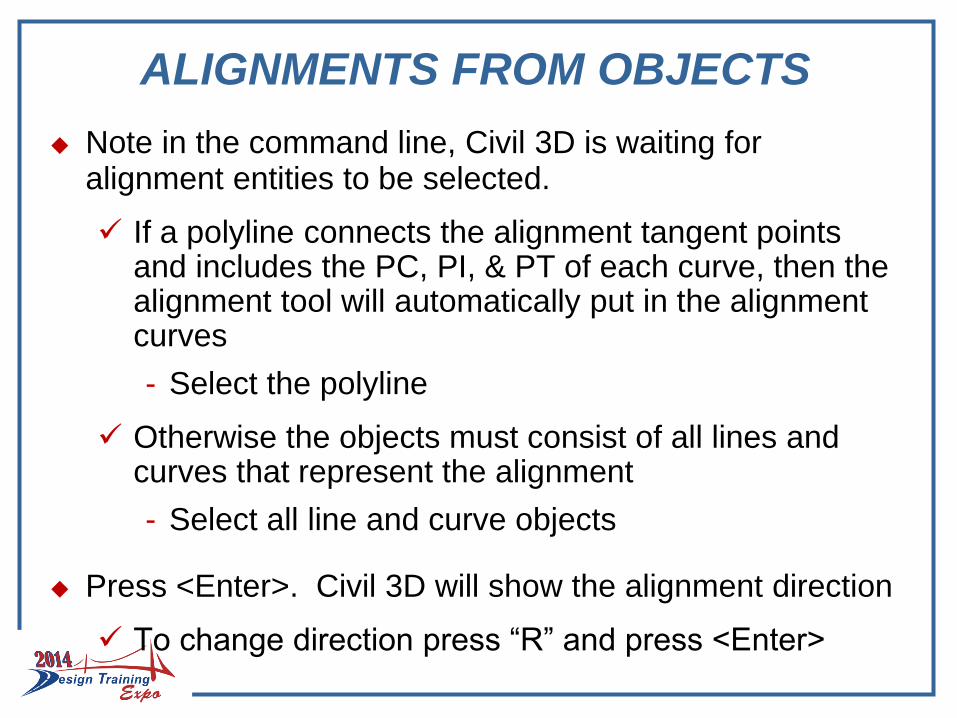
Note in the command line, Civil 3D is waiting for alignment entities to be selected.
If a polyline connects the alignment tangent points and includes the PC, PI, & PT of each curve, then the alignment tool will automatically put in the alignment curves
- Select the polyline
Otherwise the objects must consist of all lines and curves that represent the alignment
- Select all line and curve objects
Press <Enter>. Civil 3D will show the alignment direction
To change direction press “R” and press <Enter>
ALIGNMENTS FROM OBJECTS
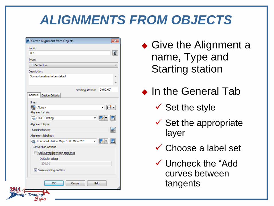
Give the Alignment a name, Type and Starting station
In the General Tab
Set the style
Set the appropriate layer
Choose a label set
Uncheck the “Add curves between tangents
ALIGNMENTS FROM CAiCE
A very simple way to create a Civil 3D alignment is to import it directly from CAiCE
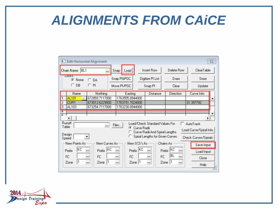
In the CAiCE menu under Geometry>Geometry Chains select “Edit Horizontal Alignment”
Load the desired alignment geometry chain
Be sure it is “loaded” showing point names and coordinates
Select the “Save Input” button to save the alignment as a *.HA file.
ALIGNMENTS FROM CAiCE

ALIGNMENTS FROM CAiCE
In Civil 3D Toolspace>Toolbox tab, expand the Miscellaneous Utilities to show the CAiCE Translator
Execute “Import CAiCE Alignments (*.HA)”
ALIGNMENTS FROM OBJECTS
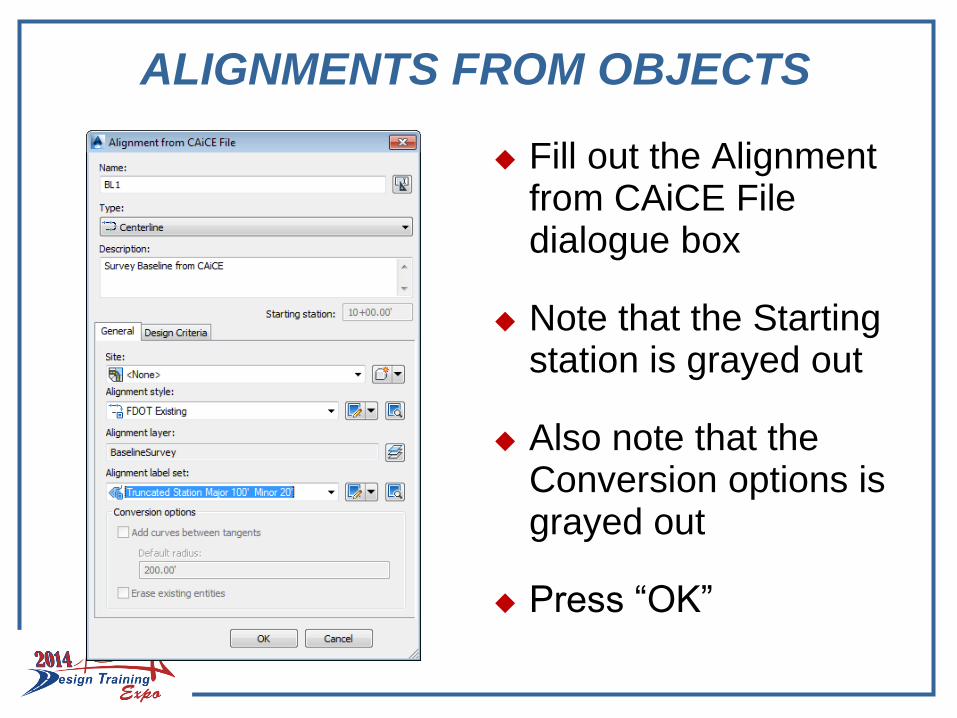
Fill out the Alignment from CAiCE File dialogue box
Note that the Starting station is grayed out
Also note that the Conversion options is grayed out
Press “OK”
ALIGNMENTS
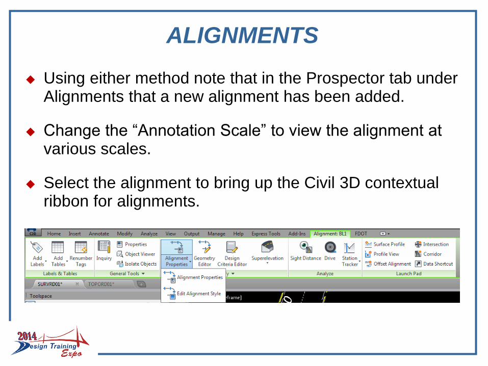
Using either method note that in the Prospector tab under Alignments that a new alignment has been added.
Change the “Annotation Scale” to view the alignment at various scales.
Select the alignment to bring up the Civil 3D contextual ribbon for alignments.
ALIGNMENTS
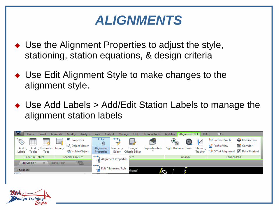
Use the Alignment Properties to adjust the style, stationing, station equations, & design criteria
Use Edit Alignment Style to make changes to the alignment style.
Use Add Labels > Add/Edit Station Labels to manage the alignment station labels
EXPORT ALIGNMENT LANDXML
When an alignment has been completed, in the Prospector, right click on the alignment name and select “Export LandXML
The “Export to LandXML” dialogue box will open and Alignments and the alignment name will already be checked. Press “OK”.
Save the alignment LandXML in the project survey folder for later use.

EXPORT ALIGNMENT LANDXML

ALIGNMENT REPORT
In Toolspace>Toolbox tab, in the upper left under the word “Toolspace” is the Edit Report Settings button.
Company name and address can be added under “Owner”

ALIGNMENT REPORT
In Toolspace>Toolbox tab, expand the Reports Manager to show Alignment and double click on “Station_and_Curve” to run the alignment report

ALIGNMENT REPORT
The “Export to XML Report” dialogue box will come up
Uncheck everything except Alignments
Press “OK”
Change output to save an Align.txt under the project Survey folder
C3D SURVEY DATABASEGROUPS-SURFACES-ALIGNMENTS
Questions?