C1.10 WELDING CONSUMABLES CATALOG - BFC Soldas Lincoln - Consumiveis.pdf · Electrode Selection...
356
www.lincolnelectric.com CATALOG WELDING CONSUMABLES C1.10
Transcript of C1.10 WELDING CONSUMABLES CATALOG - BFC Soldas Lincoln - Consumiveis.pdf · Electrode Selection...
www.lincolnelectric.com
CATALOGWELDING CONSUMABLESC1.10
Lincoln Electric delivers a wide array of products:
Equipment
Consumables
Personal Protection Equipment
Plasma Cutting Systems
Automation
Weld Fume Control
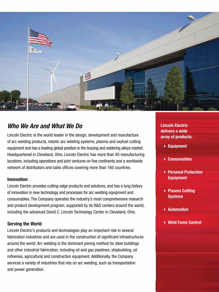
Who We Are and What We DoLincoln Electric is the world leader in the design, development and manufacture
of arc welding products, robotic arc welding systems, plasma and oxyfuel cutting
equipment and has a leading global position in the brazing and soldering alloys market.
Headquartered in Cleveland, Ohio, Lincoln Electric has more than 40 manufacturing
locations, including operations and joint ventures on five continents and a worldwide
network of distributors and sales offices covering more than 160 countries.
Innovation Lincoln Electric provides cutting-edge products and solutions, and has a long history
of innovation in new technology and processes for arc welding equipment and
consumables. The Company operates the industry’s most comprehensive research
and product development program, supported by its R&D centers around the world,
including the advanced David C. Lincoln Technology Center in Cleveland, Ohio.
Serving the WorldLincoln Electric’s products and technologies play an important role in several
fabrication industries and are used in the construction of significant infrastructures
around the world. Arc welding is the dominant joining method for steel buildings
and other industrial fabrication, including oil and gas pipelines, shipbuilding, oil
refineries, agricultural and construction equipment. Additionally, the Company
services a variety of industries that rely on arc welding, such as transportation
and power generation.
W E L D I N G C O N S U M A B L E S C A T A L O G ı 1
Table of ContentsIntroduction ................................................8
Stick Electrodes ...................................13
MIG & TIG ..........................................51
Metal-Cored .....................................73
Flux-Cored .......................................85
Submerged Arc ...............................159
Stainless & Nickel ............................193
Hardfacing..........................................235
Aluminum & Cast Iron .............................279
Packaging ..............................................291
Appendix ................................................307
LE Sales Offices .....................................352
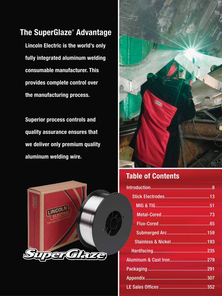
The SuperGlaze® Advantage
Lincoln Electric is the world’s only
fully integrated aluminum welding
consumable manufacturer. This
provides complete control over
the manufacturing process.
Superior process controls and
quality assurance ensures that
we deliver only premium quality
aluminum welding wire.
2 ı T H E L I N C O L N E L E C T R I C C O M P A N Y
Stick Stick ElectrodeMild Steel, CellulosicFleetweld® 5P .............................................. 14Fleetweld® 5P+ ........................................... 15Pipeliner® 6P+ ............................................ 16Fleetweld® 180 ............................................ 17Fleetweld® 35 .............................................. 18Fleetweld® 35LS .......................................... 19
Mild Steel, RutileFleetweld® 37 .............................................. 20Fleetweld® 22 .............................................. 21Fleetweld® 47 .............................................. 22
Mild Steel, High DepositionJetweld® 2 ................................................... 23Jetweld® 1 ................................................... 24
Mild Stel, Low HydrogenPipeliner® 16P .............................................. 25Excalibur® 7018 MR® ................................... 26Jetweld® LH-70 ............................................ 27Jet-LH® 78 MR® ........................................... 28Lincoln® 7018 AC ......................................... 29Excalibur® 7018-1 MR® ................................ 30Excalibur® 7028 ........................................... 31
Low Alloy, CellulosicShield-Arc® HYP+ ....................................... 32Pipeliner® 7P+ ............................................ 33Shield-Arc® 85 ............................................. 34Shield-Arc® 70+ .......................................... 35Pipeliner® 8P+ ............................................ 36Shield-Arc® 90 ............................................. 37
Low Alloy, Low HydrogenExcalibur® 7018-A1 MR® .............................. 38Excalibur® 8018-B2 MR® ............................. 39Excalibur® 8018-C1 MR® ............................. 40Excalibur® 8018-C3 MR® ............................. 41Pipeliner® 18P .............................................. 42Excalibur® 9018-B3 MR® ............................. 43Excalibur® 9018M MR® ................................ 44Excalibur® 10018-D2 MR® ........................... 45Excalibur® 11018M MR® .............................. 46Pipeliner® LH-D80 ........................................ 47Pipeliner® LH-D90 ........................................ 48Pipeliner® 19P .............................................. 49Pipeliner® LH-D100 ...................................... 50
MIG & TIGMIG WireMild Steel, BareSuperGlide® S3 ..............................................52SuperGlide® S6 ..............................................54
Mild Steel, Copper CoatedSuperArc® L-50® ............................................56SuperArc® L-56® ............................................58SuperArc® L-59® ............................................60
Low Alloy, Copper CoatedSuperArc® LA-75 ............................................62SuperArc® LA-90 ............................................64SuperArc® LA-100 ..........................................66
Mild and Low Alloy Steel PipePipeliner® 70S-G ............................................68Pipeliner® 80S-G ............................................69Pipeliner® 80Ni1 .............................................70
TIG Cut LengthMild Steel, Copper CoatedLincoln® ER70S-2...........................................71Lincoln® ER70S-6...........................................72
Metal-Cored WireMild SteelMetalshield® MC-6® .......................................74Metalshield® MC®-706 ...................................76Metalshield® MC-710XL® ...............................78
Low AlloyMetalshield® MC®-900 ...................................80Metalshield® MC®-1100 .................................82
Flux-Cored Self-Shielded (FCAW-S) WireMild Steel, Flat and HorizontalInnershield® NR®-5 ........................................86Innershield® NS-3M .......................................87Innershield® NR®-305 ....................................88Innershield® NR®-311 ....................................89Innershield® NR®-131 ....................................90
Detailed Table of Contents
W E L D I N G C O N S U M A B L E S C A T A L O G ı 3
Mild Steel, All PositionInnershield® NR®-152 ....................................91Innershield® NR®-211-MP ..............................92Innershield® NR®-203MP ...............................94Innershield® NR®-232 ....................................96Innershield® NR®-233 ....................................98
Low Alloy, Flat and HorizontalInnershield® NR®-311 Ni ..............................100Innershield® NR®-FAB 70 .............................102
Low Alloy, All PositionInnershield® NR®-212 ..................................104Innershield® NR®-203 Nickel (1%) ................106Innershield® NR®-203 Ni C Plus-H ................107Innershield® NR®-440Ni2 .............................108Innershield® NR®-207 ..................................109Pipeliner® NR®-207+ ..................................110Pipeliner® NR®-208-P ..................................111Pipeliner® NR®-208-XP ................................112Innershield® NR®-208-H ...............................113
Gas-Shielded (FCAW-S) WireMild Steel, All PositionUltraCore® 71A85 .........................................114UltraCore® 71C .............................................116UltraCore® HD-C ...........................................118UltraCore® 71A75 Dual .................................120UltraCore® 712C ...........................................122UltraCore® 712A80 .......................................124UltraCore® 712A80-H ...................................126Outershield® 71 Elite ....................................128Outershield® 71 Supreme .............................130Outershield® 71M .........................................132
Mild Steel, Flat and HorizontalUltraCore® 70C .............................................134UltraCore® 75C .............................................136Outershield® 70 ............................................138Outershield® XLH-70 ....................................140
Low Alloy, All PositionUltraCore® 81Ni1A75-H ................................142UltraCore® 81Ni1C-H ....................................144UltraCore® 81Ni2A75-H ................................146UltraCore® 81Ni2C-H ....................................148UltraCore® 81K2A75-H .................................150UltraCore® 81K2C-H .....................................152
Low Alloy, All PositionOutershield® 91K2-H ....................................154Pipeliner® 81M .............................................156Pipeliner® G80M ...........................................157Pipeliner® G90M ...........................................158
Submerged ArcFlux700 Series Active FluxLincolnweld® 760® .......................................160Lincolnweld® 761® .......................................161Lincolnweld® 780® .......................................162Lincolnweld® 781™ ......................................162
800 Series Neutral FluxLincolnweld® 860® .......................................164Lincolnweld® 865™ ......................................165Lincolnweld® 880™ ......................................166Lincolnweld® 880M® ....................................167Lincolnweld® 882™ ......................................168Lincolnweld® 888™ ......................................169Lincolnweld® 8500™ ....................................170Lincolnweld® MIL800-H™ .............................171
Special Neutral FluxLincolnweld® 960® .......................................172Lincolnweld® 980™ ......................................173Lincolnweld® WTX™ .....................................174
Flux for Seam Welding of PipeLincolnweld® 761-Pipe™ ..............................175Lincolnweld® P223™ ....................................176Lincolnweld® SPX80™ ..................................177Lincolnweld® 995N™ ....................................178
High Performance/Alloy FluxLincolnweld® A-XXX 10™ ..............................179Lincolnweld® MIL800-HPNi™ ........................180
Detailed Table of Contents
4 ı T H E L I N C O L N E L E C T R I C C O M P A N Y
Submerged ArcSolid WireMild SteelLincolnweld® L-50® ......................................181Lincolnweld® L-56® ......................................181Lincolnweld® L-60........................................182Lincolnweld® L-61® ......................................183Lincolnweld® L-S3 .......................................184Lincolnweld® LA-71 .....................................184
Low AlloyLincolnweld® L-70........................................185Lincolnweld® LA-75 .....................................185Lincolnweld® LA-81 .....................................186Lincolnweld® LA-82 .....................................186Lincolnweld® LA-84 .....................................187Lincolnweld® LA-85 .....................................187Lincolnweld® LA-90 .....................................188Lincolnweld® LA-92 .....................................188Lincolnweld® LA-93 .....................................189Lincolnweld® LA-100 ...................................189
Cored WireMild SteelLincolnweld® LC-72 .....................................190
Low AlloyLincolnweld® LAC-B2 ...................................190Lincolnweld® LAC-M2 ..................................191Lincolnweld® LAC-Ni2 ..................................191Lincolnweld® LAC-690 .................................192
Stainless & NickelStainless SteelStick ElectrodeExcalibur® 308/308L-15 ...............................194Excalibur® 308L-16 ......................................195Excalibur® 308/308H-16 ..............................196Excalibur® 308/308L-17 ...............................197Excalibur® 309/309L-15 ...............................198Excalibur® 309/309L-16 ...............................199Excalibur® 309/309L-17 ...............................200Excalibur® 316/316L-15 ...............................201Excalibur® 316/316L-16 ...............................202Excalibur® 316/316L-17 ...............................203
MIG WireBlue Max® MIG 308LSi .................................204Blue Max® MIG 309LSi .................................206Blue Max® MIG 316LSi .................................208Blue Max® LNM 307 .....................................210Blue Max® LNM 347Si ..................................211Blue Max® LNM 4462 ...................................212
Flux-Cored (FCAW-G) WireUltraCore® FC 308L ......................................213UltraCore® FCP 308L ....................................214UltraCore® FC 309L ......................................216UltraCore® FCP 309L ....................................218UltraCore® FC 316L ......................................220UltraCore® FCP 316L ....................................222
Submerged Arc WireLincolnweld® S308/308L ..............................224Lincolnweld® S309/309L ..............................225Lincolnweld® S316/316L ..............................226
Submerged Arc FluxLincolnweld® P2007™ ..................................227Lincolnweld® P3000™ ..................................228Lincolnweld® P4000™ ..................................228Lincolnweld® ST-100™ .................................229
TIG Cut LengthLincoln® ER308/308L ...................................230Lincoln® ER309/309L ...................................231Lincoln® ER316/316L ...................................232Blue Max® LNT 4462 ....................................233
Metal-Cored WireOutershield® MC®-409 .................................234
HardfacingStick ElectrodeBuild-UpWearshield® BU ............................................236
Metal-to-Metal WearWearshield® MI ............................................237Wearshield® Mangjet® ..................................238
Severe ImpactWearshield® 15CrMn ....................................239Wearshield® FROG MANG® ...........................240
Detailed Table of Contents
W E L D I N G C O N S U M A B L E S C A T A L O G ı 5
Abrasion Plus ImpactWearshield® ABR ..........................................241Wearshield® 44 ............................................242
Metal-to-Earth WearWearshield® ME ...........................................243
Severe AbrasionWearshield® 60 ............................................244
Maintenance and RepairBlue Max® 2100 ...........................................245
Flux-Cored (FCAW-G) WireBuild-UpLincore® BU-G ..............................................246
Metal-to-MetalLincore® 55-G ..............................................247
Metal-Cored WIreBuild-UpLincore® 60-G ..............................................248
Flux-Cored (FCAW-S) WireBuild-UpLincore® BU..................................................249Lincore® 33 ..................................................250
Metal-to-MetalLincore® 40-O ..............................................251Lincore® 55 ..................................................252Lincore® T & D .............................................253
Severe ImpactLincore® M ...................................................254Lincore® 15CrMn ..........................................255Lincore® FROG MANG® .................................256
Abrasion Plus ImpactLincore® 50 ..................................................257
Severe AbrasionLincore® 60-O ..............................................258Lincore® 65-O ..............................................259
Metal-Cored Submerged Arc WireBuild-UpLincore® 30-S ..............................................260
Metal-to-Metal, Build UpLincore® 32-S ..............................................261Lincore® 35-S ..............................................262
Metal-to-MetalLincore® 40-S ..............................................263Lincore® 42-S ..............................................264
Roll Rebuilding, Build UpLincore® 20 ..................................................265Lincore® 8620 ..............................................266Lincore® 4130 ..............................................267
Roll Rebuilding, Metal-to-MetalLincore® 410 ................................................268Lincore® 410NiMo ........................................269Lincore® 423L ..............................................270Lincore® 423Cr ............................................271Lincore® 420 ................................................272Lincore® 96S ................................................273Lincore® 102W .............................................274Lincore® 102HC ...........................................275
Submerged Arc FluxHardfacingLincolnweld® A-96-S ....................................276Lincolnweld® H-535™ ...................................276Lincolnweld® H-560™ ...................................277
NeutralLincolnweld® 801® .......................................277Lincolnweld® 802® .......................................278Lincolnweld® 803™ ......................................278
Detailed Table of Contents

6 ı T H E L I N C O L N E L E C T R I C C O M P A N Y
Aluminum & Cast IronAluminumMIG WireSuperGlaze® 4043 ........................................280SuperGlaze® 4047 ........................................281SuperGlaze® 5183 ........................................282SuperGlaze® 5356 ........................................283SuperGlaze® 5554 ........................................284SuperGlaze® 5556 ........................................285
TIG Cut LengthSuperGlaze® 4043 ........................................286SuperGlaze® 5356 ........................................287
Cast IronStick ElectrodeSoftweld® 55Ni .............................................288Softweld® 99Ni .............................................289Ferroweld™ ..................................................290
PackagingOptionsTubes, Cans & Cartons..................................292Reels & Stem ...............................................294Spools ..........................................................296Coils, Boxes & Bags ......................................298Drums & Pails ..............................................300
Storage and HandlingStick Electrode .............................................302Metal-Cored & Flux-Cored Wire ....................304Submerged Arc Flux & Wire ..........................305
AppendixAWS Classification System
Stick ............................................................308MIG, TIG & Metal-Cored ................................309Flux-Cored ...................................................310Submerged Arc ............................................312
General InformationStick ElectrodeTypes of Coating & Current ...........................314ASME Boiler & Pressure Vessel Code ............315
Submerged ArcFlux Types & General Characteristics ............316Selecting Flux/Wire Combinations ................317
HardfacingCross Checking ............................................319
AluminumTypical Operating Procedures .......................320Typical Joint Designs ....................................322
Innershield®
Wire Selection Guide ....................................323
Pipeliner®
Electrode Selection Guide .............................325LH-D80/90/100 Welding Guidelines ..............328EN and ISO Classifications ............................329
Agency Approvals ........................................331
Safety Guidelines .........................................344
LE Sales OfficesDistrict Sales Offices ....................................352
Detailed Table of Contents
W E L D I N G C O N S U M A B L E S C A T A L O G ı 7
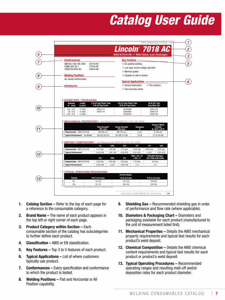
1. Catalog Section – Refer to the top of each page for a reference to the consumable category.
2. Brand Name – The name of each product appears in the top left or right corner of each page.
3. Product Category within Section – Each consumable section of the catalog has subcategories to further define each product.
4. Classification – AWS or EN classification.
5. Key Features – Top 3 to 5 features of each product.
6. Typical Applications – List of where customers typically use product.
7. Conformances – Every specification and conformance to which the product is tested.
8. Welding Positions – Flat and Horizontal or All Position capability.
9. Shielding Gas – Recommended shielding gas in order of performance and flow rate (where applicable).
10. Diameters & Packaging Chart – Diameters and packaging available for each product (manufactured to the unit of measurement listed first).
11. Mechanical Properties – Details the AWS mechanical property requirements and typical test results for each product’s weld deposit.
12. Chemical Composition – Details the AWS chemical content requirements and typical test results for each product or product’s weld deposit.
13. Typical Operating Procedures – Recommended operating ranges and resulting melt-off and/or deposition rates for each product diameter.
W E L D I N G C O N S U M A B L E S C A T A L O G ı 29
STICK (SMAW) ELECTRODE
(1)Typical all weld metal. (2)Measured with 0.2% offset. (3)See test results disclaimer on pg. 6. (4)Preferred polarity is listed first.
Lincoln ® 7018 AC
Welding Positions
Typical ApplicationsAll, except vertical down
General fabrication
Tack and skip welds
Thin sections
AC polarity welding
Low open circuit voltage operation
Minimal spatter
Capable of cold re-strikes
Conformances
AWS E7018 H8 • Mild Steel, Low Hydrogen
Key FeaturesAWS A5.1/A5.1M: 2004ASME SFA-A5.1:CWB/CSA W48-06:
E7018 H8E7018 H8E4918-H8
DIAMETERS / PACKAGINGDiameter Length 1 lb (0.5 kg) Plastic Tube
6 lb (3.6 kg) Carton5 lb (2.3 kg) Plastic Tube
20 lb (9.1 kg) Carton50 lb (22.7 kg)Easy Open Canin (mm) in (mm)
3/321/8
5/32
(2.4)(3.2)(4.0)
14 (350)14 (350)14 (350)
ED031714ED031715
ED030568ED030569ED032444
ED031732ED031734ED031738
TYPICAL OPERATING PROCEDURESCurrent (Amps)
Polarity 3/32 in (2.4 mm) 1/8 in (3.2 mm) 5/32 in (4.0 mm)
AC 75-120 105-150 130-200
DC+ 70-115 100-140 120-185
MECHANICAL PROPERTIES(1) – As Required per AWS A5.1/A5.1M: 2004
Yield Strength(2) Tensile Strength ElongationCharpy V-Notch
J (ft•lbf)MPa (ksi) MPa (ksi) % @ -29°C (-20°F)
Requirements - AWS E7018 H8 400 (58) min. 490 (70) min. 2 min. 27 (20) min.
Typical Performance(3) - As-Welded 435-625 (63-91) 515-685 (75-99) 23-29 27-76 (20-56)
DEPOSIT COMPOSITION(1) – As Required per AWS A5.1/A5.1M: 2004%C %Mn %Si %P %S %Ni
Requirements - AWS E7018 H8 0.15 max. 1.60 max. 0.75 max. 0.035 max. 0.035 max. 0.30 max.
Typical Performance(3) 0.04-0.06 1.00-1.60 0.32-0.63 0.01-0.02 0.01 0.01-0.03
%Cr %Mo %V%Mn + Ni + Cr
+ Mo + VDiffusible Hydrogen
(mL/100g weld metal)
Requirements - AWS E7018 H8 0.20 max. 0.30 max. 0.08 max. 1.75 max. 8.0 max.
Typical Performance(3) 0.03-0.08 0.01 0.02-0.05 1.13 2-4
34
5
6
7
8
9
1
Shielding Gas
12
13
11
10
2
Catalog User Guide
8 ı T H E L I N C O L N E L E C T R I C C O M P A N Y
INTRODUCTION
W E L D I N G C O N S U M A B L E S C A T A L O G ı 9
INTRODUCTION
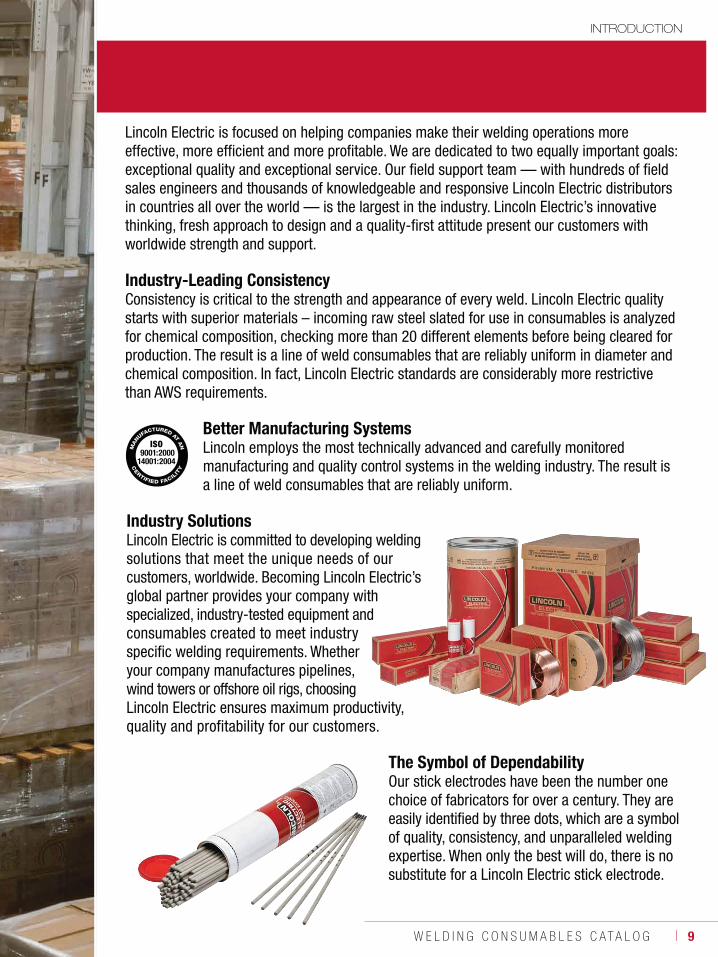
Lincoln Electric is focused on helping companies make their welding operations more effective, more efficient and more profitable. We are dedicated to two equally important goals: exceptional quality and exceptional service. Our field support team — with hundreds of field sales engineers and thousands of knowledgeable and responsive Lincoln Electric distributors in countries all over the world — is the largest in the industry. Lincoln Electric’s innovative thinking, fresh approach to design and a quality-first attitude present our customers with worldwide strength and support.
Industry-Leading Consistency Consistency is critical to the strength and appearance of every weld. Lincoln Electric quality starts with superior materials – incoming raw steel slated for use in consumables is analyzed for chemical composition, checking more than 20 different elements before being cleared for production. The result is a line of weld consumables that are reliably uniform in diameter and chemical composition. In fact, Lincoln Electric standards are considerably more restrictive than AWS requirements.
Better Manufacturing Systems Lincoln employs the most technically advanced and carefully monitored manufacturing and quality control systems in the welding industry. The result is a line of weld consumables that are reliably uniform.
The Symbol of Dependability Our stick electrodes have been the number one choice of fabricators for over a century. They are easily identified by three dots, which are a symbol of quality, consistency, and unparalleled welding expertise. When only the best will do, there is no substitute for a Lincoln Electric stick electrode.
ISO 9001:200014001:2004
Industry Solutions Lincoln Electric is committed to developing weldingsolutions that meet the unique needs of our customers, worldwide. Becoming Lincoln Electric’s global partner provides your company with specialized, industry-tested equipment and consumables created to meet industry specific welding requirements. Whether your company manufactures pipelines, wind towers or offshore oil rigs, choosing Lincoln Electric ensures maximum productivity, quality and profitability for our customers.
10 ı T H E L I N C O L N E L E C T R I C C O M P A N Y
INTRODUCTION
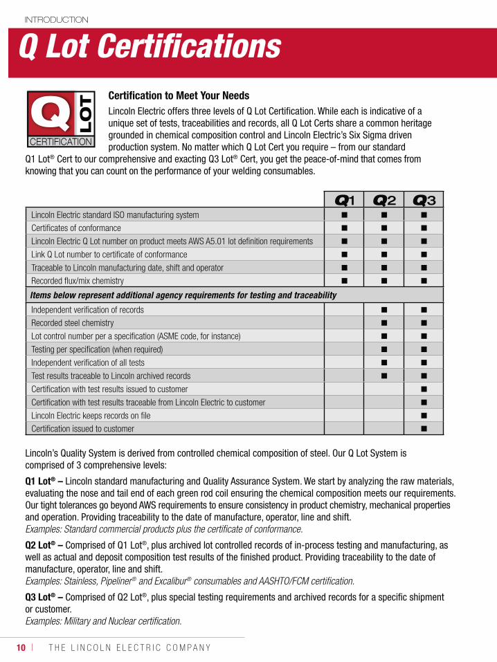
Certification to Meet Your NeedsLincoln Electric offers three levels of Q Lot Certification. While each is indicative of a unique set of tests, traceabilities and records, all Q Lot Certs share a common heritage grounded in chemical composition control and Lincoln Electric’s Six Sigma driven production system. No matter which Q Lot Cert you require – from our standard
Q1 Lot® Cert to our comprehensive and exacting Q3 Lot® Cert, you get the peace-of-mind that comes from knowing that you can count on the performance of your welding consumables.
Q1 Q2 Q3Lincoln Electric standard ISO manufacturing system
Certificates of conformance
Lincoln Electric Q Lot number on product meets AWS A5.01 lot definition requirements
Link Q Lot number to certificate of conformance
Traceable to Lincoln manufacturing date, shift and operator
Recorded flux/mix chemistry
Items below represent additional agency requirements for testing and traceability
Independent verification of records
Recorded steel chemistry
Lot control number per a specification (ASME code, for instance)
Testing per specification (when required)
Independent verification of all tests
Test results traceable to Lincoln archived records
Certification with test results issued to customer
Certification with test results traceable from Lincoln Electric to customer
Lincoln Electric keeps records on file
Certification issued to customer
Lincoln’s Quality System is derived from controlled chemical composition of steel. Our Q Lot System is comprised of 3 comprehensive levels:
Q1 Lot® – Lincoln standard manufacturing and Quality Assurance System. We start by analyzing the raw materials, evaluating the nose and tail end of each green rod coil ensuring the chemical composition meets our requirements. Our tight tolerances go beyond AWS requirements to ensure consistency in product chemistry, mechanical properties and operation. Providing traceability to the date of manufacture, operator, line and shift. Examples: Standard commercial products plus the certificate of conformance.
Q2 Lot® – Comprised of Q1 Lot®, plus archived lot controlled records of in-process testing and manufacturing, aswell as actual and deposit composition test results of the finished product. Providing traceability to the date of manufacture, operator, line and shift. Examples: Stainless, Pipeliner® and Excalibur® consumables and AASHTO/FCM certification.
Q3 Lot® – Comprised of Q2 Lot®, plus special testing requirements and archived records for a specific shipment or customer. Examples: Military and Nuclear certification.
Q Lot Certifications

W E L D I N G C O N S U M A B L E S C A T A L O G ı 11
INTRODUCTION
EN 10204 Inspection Documents
Testing Levels per AWS A5.01 Filler Metal Procurement Guidelines
Examples of Lincoln Electric Options
Type 2.1 States “Products are in compliance with requirements of the order (WITHOUT any test results).
Schedule FThe level of testing shall be the manufacturer’s standard. A statement, “the product supplied will meet the requirements of the applicable AWS standard, when tested in accordance with that standard” and a summary of the typical properties of the material, when tested in that manner, shall be supplied upon written request.
Lincoln Electric “3 year” Certificate of Conformance applicable to a Q1 Lot®.
Type 2.2 States ”Products are in compliance with requirements of the order (includes non-specific test results – NOT ACTUALS from the lot in question).
Schedule GTest results shall be supplied from any production run of the product made within the twelve months preceding the date of the purchase order. This shall include the results of all tests prescribed for that classification in the AWS standard.
Lincoln Electric “1 year” Certificate of Conformance applicable to a Q1 Lot®.
Type 3.1States “Products are in compliance with requirements of the order and includes ACTUAL test results for some requirements, but not all.
Schedule HChemical analysis of each lot shipped shall be supplied by the manufacturer. The analysis shall include those elements prescribed for that classification in the AWS standard.”
Lincoln Electric “Q1 with Schedule H” Certificate of Actual Results on each S4 lot of SAW wire. Lincoln Electric “Q2” Certified Material Test Reports for products such as Excalibur® and Ultracore® stainless products.
Schedule IActual results of the tests called for in Table 2 of AWS A5.01 shall be supplied by the manufacturer for each lot shipped. These tests represent a consensus of those frequently requested for consumables certification; however, they do not necessarily include all tests required for Schedule J. The tests shall be performed as prescribed for that classification in the AWS standard.
Lincoln Electric “Q2” Certified Material Test Reports for products such as Pipeliner® brand.
Schedule JActual results of all of the tests prescribed for that classification in the AWS standard shall be supplied by the manufacturer for each lot shipped.”
Lincoln Electric “Q2” Certified Material Test Reports for stainless solid wires such as BlueMax® MIG, Lincolnweld® stainless subarc wires, and Lincoln® stainless cut length products.
Schedule KIn addition to, or in place of, any of the tests called for in the AWS standard, the purchaser may require other tests (such as testing after a specified heat treatment). In all such cases, the purchaser shall identify on the purchase order the specific tests that are to be conducted, the procedures to be followed, the requirements that shall be met and the results to be reported by the manufacturer.
Lincoln Electric “Q3” Certified Material Test Reports to specific customer requirements. Lincoln Electric “Q1 with Schedule K” Certificate of Actual Results for composition on each lot of SAW flux.
Q Lot Certifications
12 ı T H E L I N C O L N E L E C T R I C C O M P A N Y
INTRODUCTION
TEST RESULTSTest results for mechanical properties, deposit or electrode composition and diffusible hydrogen levels were obtained from a weld produced and tested according to prescribed standards, and should not be assumed to be the expected results in a particular application or weldment. Actual results will vary depending on many factors, including, but not limited to, weld procedure, plate chemistry and temperature, weldment design and fabrication methods. Users are cautioned to confirm by qualification testing, or other appropriate means, the suitability of any welding consumable and procedure before use in the intended application.
CUSTOMER ASSISTANCE POLICYThe Lincoln Electric Company is manufacturing and selling high quality welding equipment, consumables, and cutting equipment. Our challenge is to meet the needs of our customers and to exceed their expectations. On occasion, purchasers may ask Lincoln Electric for information or advice about their use of our products. Our employees respond to inquiries to the best of their ability based on information provided to them by the customersand the knowledge they may have concerning the application. Our employees, however, are not in a position to verify the information provided or to evaluate the engineering requirements for the particular weldment. Accordingly,Lincoln Electric does not warrant or guarantee or assume any liability with respect to such information or advice. Moreover, the provision of such information or advice does not create, expand, or alter any warranty on our products. Any express or implied warranty that might arise from the information or advice, including any implied warranty of merchantability or any warranty of fitness for any customers’ particular purpose is specifically disclaimed.
Lincoln Electric is a responsive manufacturer, but the selection and use of specific products sold by Lincoln Electric is solely within the control of, and remains the sole responsibility of the customer. Many variables beyond the control of Lincoln Electric affect the results obtained in applying these types of fabrication methods and service requirements.
Subject to Change – This information is accurate to the best of our knowledge at the time of printing. Please refer to www.lincolnelectric.com for any updated information.
Consumable AWS Certificates:http://www.lincolnelectric.com/LEExtranet/MyLincolnCerts/site/default.aspx
D1.8 Certificate Center: http://www.lincolnelectric.com/LEExtranet/MyLincolnCerts/site/awsd.aspx
Material Safety Data Sheets (MSDS): http://www.lincolnelectric.com/en-us/support/msds/Pages/msds.aspx
ANSI Z49.1, E205 Safety Booklet: http://www.lincolnelectric.com/en-us/education-center/welding-safety/documents/e205.pdf
More Welding Safety Materials can be found at: http://www.lincolnelectric.com/en-us/education-center/welding-safety/Pages/welding-safety.aspx
Important Information On Our Website
Disclaimers
W E L D I N G C O N S U M A B L E S C A T A L O G ı 13
SMAW CONSUMABLES
STICKMild Steel, CellulosicFleetweld® 5P ................................................ 14Fleetweld® 5P+ ............................................. 15Pipeliner® 6P+ .............................................. 16Fleetweld® 180 .............................................. 17Fleetweld® 35 ................................................ 18Fleetweld® 35LS ............................................ 19
Mild Steel, RutileFleetweld® 37 ................................................ 20Fleetweld® 22 ................................................ 21Fleetweld® 47 ................................................ 22
Mild Steel, High DepositionJetweld® 2 ..................................................... 23Jetweld® 1 ..................................................... 24
Mild Stel, Low HydrogenPipeliner® 16P ................................................ 25Excalibur® 7018 MR® ..................................... 26Jetweld® LH-70 ............................................. 27Jet-LH® 78 MR® ............................................. 28Lincoln® 7018 AC ........................................... 29Excalibur® 7018-1 MR® ................................. 30Excalibur® 7028 ............................................. 31
Low Alloy, CellulosicShield-Arc® HYP+ ......................................... 32Pipeliner® 7P+ .............................................. 33Shield-Arc® 85 ............................................... 34Shield-Arc® 70+ ........................................... 35Pipeliner® 8P+ .............................................. 36Shield-Arc® 90 ............................................... 37
Low Alloy, Low HydrogenExcalibur® 7018-A1 MR® ............................... 38Excalibur® 8018-B2 MR® ............................... 39Excalibur® 8018-C1 MR® ............................... 40Excalibur® 8018-C3 MR® ............................... 41Pipeliner® 18P ................................................ 42Excalibur® 9018-B3 MR® ............................... 43Excalibur® 9018M MR® .................................. 44Excalibur® 10018-D2 MR® ............................. 45Excalibur® 11018M MR® ................................ 46Pipeliner® LH-D80 .......................................... 47Pipeliner® LH-D90 .......................................... 48Pipeliner® 19P ................................................ 49Pipeliner® LH-D100 ........................................ 50
14 ı T H E L I N C O L N E L E C T R I C C O M P A N Y
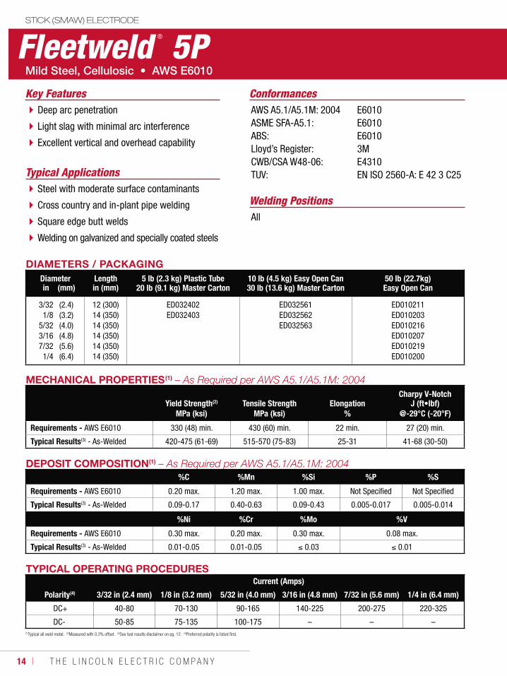
Fleetweld ® 5PSTICK (SMAW) ELECTRODE
Welding Positions
Typical Applications
All
Steel with moderate surface contaminants
Cross country and in-plant pipe welding
Square edge butt welds
Welding on galvanized and specially coated steels
Deep arc penetration
Light slag with minimal arc interference
Excellent vertical and overhead capability
Key Features ConformancesAWS A5.1/A5.1M: 2004ASME SFA-A5.1:ABS:Lloyd’s Register:CWB/CSA W48-06:TUV:
E6010E6010E60103ME4310EN ISO 2560-A: E 42 3 C25
DIAMETERS / PACKAGINGDiameter Length 5 lb (2.3 kg) Plastic Tube
20 lb (9.1 kg) Master Carton10 lb (4.5 kg) Easy Open Can30 lb (13.6 kg) Master Carton
50 lb (22.7kg)Easy Open Canin (mm) in (mm)
3/321/8
5/323/167/321/4
(2.4)(3.2)(4.0)(4.8)(5.6)(6.4)
12 (300)14 (350)14 (350)14 (350)14 (350)14 (350)
ED032402ED032403
ED032561ED032562ED032563
ED010211ED010203ED010216ED010207ED010219ED010200
MECHANICAL PROPERTIES(1)
Yield Strength(2) Tensile Strength ElongationCharpy V-Notch
J (ft•lbf)MPa (ksi) MPa (ksi) % @-29°C (-20°F)
Requirements - AWS E6010 330 (48) min. 430 (60) min. 22 min. 27 (20) min.
Typical Results(3) - As-Welded 420-475 (61-69) 515-570 (75-83) 25-31 41-68 (30-50)
TYPICAL OPERATING PROCEDURESCurrent (Amps)
Polarity(4) 3/32 in (2.4 mm) 1/8 in (3.2 mm) 5/32 in (4.0 mm) 3/16 in (4.8 mm) 7/32 in (5.6 mm) 1/4 in (6.4 mm)
DC+ 40-80 70-130 90-165 140-225 200-275 220-325
DC- 50-85 75-135 100-175 – – –(1)Typical all weld metal. (2)Measured with 0.2% offset. (3)See test results disclaimer on pg. 12. (4)Preferred polarity is listed first.
DEPOSIT COMPOSITION(1)
%C %Mn %Si %P %S
Requirements - AWS E6010 0.20 max. 1.20 max. 1.00 max. Not Specified Not Specified
Typical Results(3) - As-Welded 0.09-0.17 0.40-0.63 0.09-0.43 0.005-0.017 0.005-0.014
%Ni %Cr %Mo %V
Requirements - AWS E6010 0.30 max. 0.20 max. 0.30 max. 0.08 max.
Typical Results(3) - As-Welded 0.01-0.05 0.01-0.05 0.03 0.01
W E L D I N G C O N S U M A B L E S C A T A L O G ı 15
STICK (SMAW) ELECTRODE
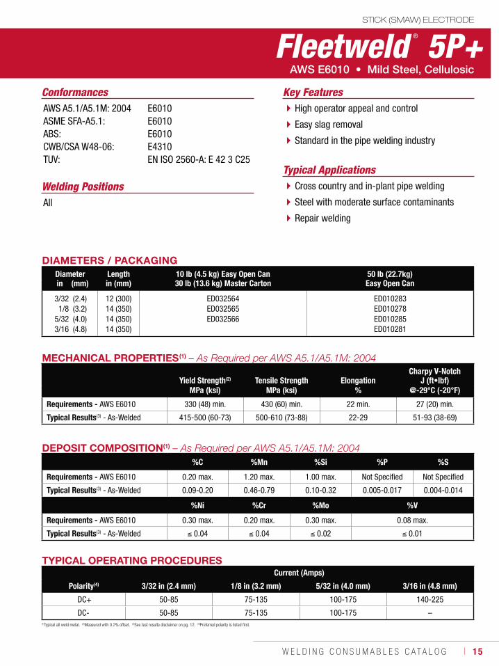
Welding PositionsTypical Applications
All
Cross country and in-plant pipe welding
Steel with moderate surface contaminants
Repair welding
High operator appeal and control
Easy slag removal
Standard in the pipe welding industry
Conformances Key FeaturesAWS A5.1/A5.1M: 2004ASME SFA-A5.1:ABS:CWB/CSA W48-06:TUV:
E6010E6010E6010E4310EN ISO 2560-A: E 42 3 C25
DIAMETERS / PACKAGINGDiameter Length 10 lb (4.5 kg) Easy Open Can
30 lb (13.6 kg) Master Carton50 lb (22.7kg) Easy Open Canin (mm) in (mm)
3/321/8
5/323/16
(2.4)(3.2)(4.0)(4.8)
12 (300)14 (350)14 (350)14 (350)
ED032564ED032565ED032566
ED010283ED010278ED010285ED010281
MECHANICAL PROPERTIES(1)
Yield Strength(2) Tensile Strength ElongationCharpy V-Notch
J (ft•lbf)MPa (ksi) MPa (ksi) % @-29°C (-20°F)
Requirements - AWS E6010 330 (48) min. 430 (60) min. 22 min. 27 (20) min.
Typical Results(3) - As-Welded 415-500 (60-73) 500-610 (73-88) 22-29 51-93 (38-69)
DEPOSIT COMPOSITION(1)
%C %Mn %Si %P %S
Requirements - AWS E6010 0.20 max. 1.20 max. 1.00 max. Not Specified Not Specified
Typical Results(3) - As-Welded 0.09-0.20 0.46-0.79 0.10-0.32 0.005-0.017 0.004-0.014
%Ni %Cr %Mo %V
Requirements - AWS E6010 0.30 max. 0.20 max. 0.30 max. 0.08 max.
Typical Results(3) - As-Welded 0.04 0.04 0.02 0.01
(1)Typical all weld metal. (2)Measured with 0.2% offset. (3)See test results disclaimer on pg. 12. (4)Preferred polarity is listed first.
TYPICAL OPERATING PROCEDURESCurrent (Amps)
Polarity(4) 3/32 in (2.4 mm) 1/8 in (3.2 mm) 5/32 in (4.0 mm) 3/16 in (4.8 mm)
DC+ 50-85 75-135 100-175 140-225
DC- 50-85 75-135 100-175 –
Fleetweld ® 5P+
16 ı T H E L I N C O L N E L E C T R I C C O M P A N Y
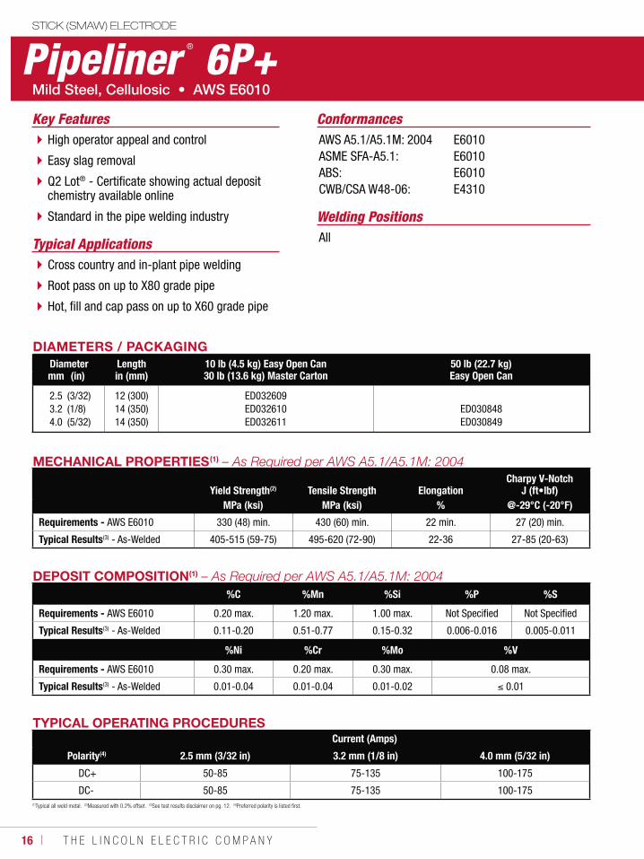
Pipeliner ® 6P+ STICK (SMAW) ELECTRODE
Welding Positions
Typical Applications All
Cross country and in-plant pipe welding
Root pass on up to X80 grade pipe
Hot, fill and cap pass on up to X60 grade pipe
High operator appeal and control
Easy slag removal
Q2 Lot® - Certificate showing actual deposit chemistry available online
Standard in the pipe welding industry
ConformancesKey FeaturesAWS A5.1/A5.1M: 2004ASME SFA-A5.1:ABS:CWB/CSA W48-06:
E6010E6010E6010E4310
DIAMETERS / PACKAGINGDiameter Length 10 lb (4.5 kg) Easy Open Can
30 lb (13.6 kg) Master Carton50 lb (22.7 kg) Easy Open Canmm (in) in (mm)
2.53.24.0
(3/32)(1/8)(5/32)
12 (300)14 (350)14 (350)
ED032609ED032610ED032611
ED030848ED030849
MECHANICAL PROPERTIES(1)
Yield Strength(2) Tensile Strength ElongationCharpy V-Notch
J (ft•lbf)MPa (ksi) MPa (ksi) % @-29°C (-20°F)
Requirements - AWS E6010 330 (48) min. 430 (60) min. 22 min. 27 (20) min.
Typical Results(3) - As-Welded 405-515 (59-75) 495-620 (72-90) 22-36 27-85 (20-63)
DEPOSIT COMPOSITION(1)
%C %Mn %Si %P %S
Requirements - AWS E6010 0.20 max. 1.20 max. 1.00 max. Not Specified Not Specified
Typical Results(3) - As-Welded 0.11-0.20 0.51-0.77 0.15-0.32 0.006-0.016 0.005-0.011
%Ni %Cr %Mo %V
Requirements - AWS E6010 0.30 max. 0.20 max. 0.30 max. 0.08 max.
Typical Results(3) - As-Welded 0.01-0.04 0.01-0.04 0.01-0.02 0.01
TYPICAL OPERATING PROCEDURESCurrent (Amps)
Polarity(4) 2.5 mm (3/32 in) 3.2 mm (1/8 in) 4.0 mm (5/32 in)
DC+ 50-85 75-135 100-175
DC- 50-85 75-135 100-175(1)Typical all weld metal. (2)Measured with 0.2% offset. (3)See test results disclaimer on pg. 12. (4)Preferred polarity is listed first.
W E L D I N G C O N S U M A B L E S C A T A L O G ı 17
STICK (SMAW) ELECTRODE
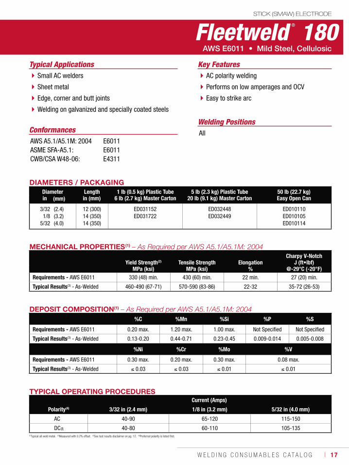
Fleetweld ® 180
Welding Positions
Typical Applications
All
Small AC welders
Sheet metal
Edge, corner and butt joints
Welding on galvanized and specially coated steels
AC polarity welding
Performs on low amperages and OCV
Easy to strike arc
Conformances
Key Features
AWS A5.1/A5.1M: 2004ASME SFA-A5.1:CWB/CSA W48-06:
E6011E6011E4311
DIAMETERS / PACKAGINGDiameter Length 1 lb (0.5 kg) Plastic Tube
6 lb (2.7 kg) Master Carton5 lb (2.3 kg) Plastic Tube
20 lb (9.1 kg) Master Carton50 lb (22.7 kg) Easy Open Canin (mm) in (mm)
3/321/8
5/32
(2.4)(3.2)(4.0)
12 (300)14 (350)14 (350)
ED031152ED031722
ED032448ED032449
ED010110ED010105ED010114
MECHANICAL PROPERTIES(1)
Yield Strength(2) Tensile Strength ElongationCharpy V-Notch
J (ft•lbf)MPa (ksi) MPa (ksi) % @-29°C (-20°F)
Requirements - AWS E6011 330 (48) min. 430 (60) min. 22 min. 27 (20) min.
Typical Results(3) - As-Welded 460-490 (67-71) 570-590 (83-86) 22-32 35-72 (26-53)
DEPOSIT COMPOSITION(1)
%C %Mn %Si %P %S
Requirements - AWS E6011 0.20 max. 1.20 max. 1.00 max. Not Specified Not Specified
Typical Results(3) - As-Welded 0.13-0.20 0.44-0.71 0.23-0.45 0.009-0.014 0.005-0.008
%Ni %Cr %Mo %V
Requirements - AWS E6011 0.30 max. 0.20 max. 0.30 max. 0.08 max.
Typical Results(3) - As-Welded 0.03 0.03 0.01 0.01
TYPICAL OPERATING PROCEDURESCurrent (Amps)
Polarity(4) 3/32 in (2.4 mm) 1/8 in (3.2 mm) 5/32 in (4.0 mm)
AC 40-90 65-120 115-150
DC± 40-80 60-110 105-135(1)Typical all weld metal. (2)Measured with 0.2% offset. (3)See test results disclaimer on pg. 12. (4)Preferred polarity is listed first.
18 ı T H E L I N C O L N E L E C T R I C C O M P A N Y
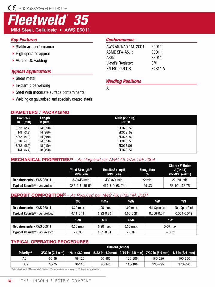
Fleetweld ® 35STICK (SMAW) ELECTRODE
Welding Positions
Typical Applications
All
Sheet metal
In-plant pipe welding
Steel with moderate surface contaminants
Welding on galvanized and specially coated steels
Stable arc performance
High operator appeal
AC and DC welding
ConformancesKey FeaturesAWS A5.1/A5.1M: 2004ASME SFA-A5.1:ABS:Lloyd’s Register:EN ISO 2560-B:
E6011E6011E60113ME4311 A
DIAMETERS / PACKAGINGDiameter Length 50 lb (22.7 kg)
Cartonin (mm) in (mm)
3/321/8
5/323/167/321/4
(2.4)(3.2)(4.0)(4.8)(5.6)(6.4)
14 (350)14 (350)14 (350)14 (350)18 (450)18 (450)
ED028152 ED028153 ED028154 ED028155 ED032301 ED028157
MECHANICAL PROPERTIES(1)
Yield Strength(2) Tensile Strength ElongationCharpy V-Notch
J (ft•lbf)MPa (ksi) MPa (ksi) % @-29°C (-20°F)
Requirements - AWS E6011 330 (48) min. 430 (60) min. 22 min. 27 (20) min.
Typical Results(3) - As-Welded 385-415 (56-60) 470-510 (68-74) 26-33 56-101 (42-75)
DEPOSIT COMPOSITION(1)
%C %Mn %Si %P %S
Requirements - AWS E6011 0.20 max. 1.20 max. 1.00 max. Not Specified Not Specified
Typical Results(3) - As-Welded 0.11-0.16 0.32-0.60 0.09-0.28 0.006-0.011 0.004-0.013
%Ni %Cr %Mo %V
Requirements - AWS E6011 0.30 max. 0.20 max. 0.30 max. 0.08 max.
Typical Results(3) - As-Welded 0.06 0.01-0.04 0.02 0.01
TYPICAL OPERATING PROCEDURESCurrent (Amps)
Polarity(4) 3/32 in (2.4 mm) 1/8 in (3.2 mm) 5/32 in (4.0 mm) 3/16 in (4.8 mm) 7/32 in (5.6 mm) 1/4 in (6.4 mm)
AC 50-85 75-120 90-160 120-200 150-260 190-300
DC± 40-75 70-110 80-145 110-180 135-235 170-270 (1)Typical all weld metal. (2)Measured with 0.2% offset. (3)See test results disclaimer on pg. 12. (4)Preferred polarity is listed first.
W E L D I N G C O N S U M A B L E S C A T A L O G ı 19
STICK (SMAW) ELECTRODE
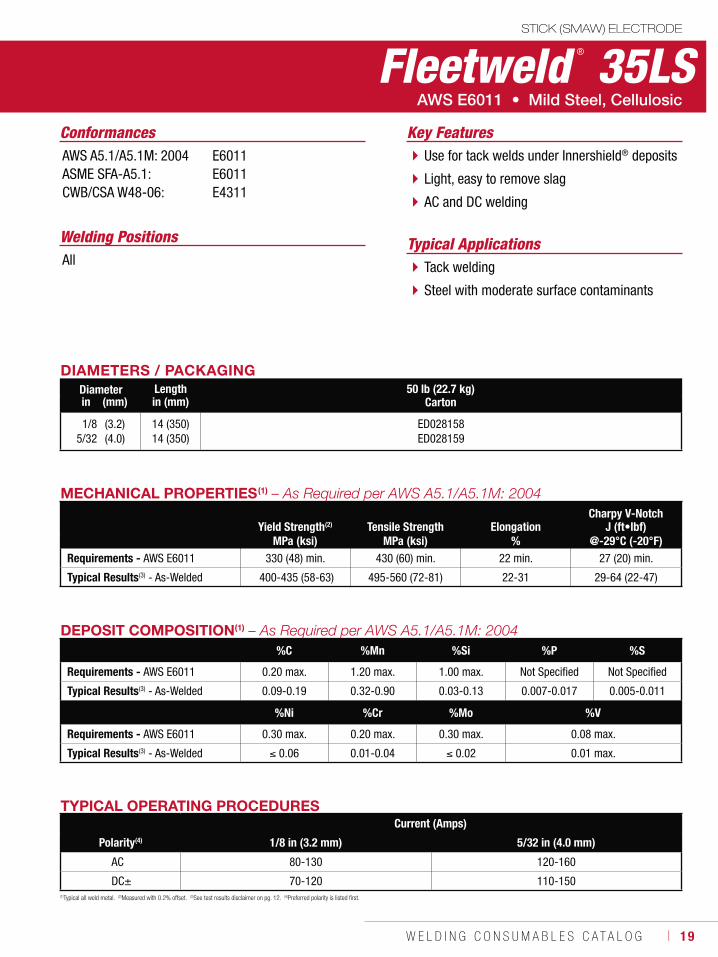
Fleetweld ® 35LS
Welding Positions Typical ApplicationsAll Tack welding
Steel with moderate surface contaminants
Use for tack welds under Innershield® deposits
Light, easy to remove slag
AC and DC welding
Conformances Key FeaturesAWS A5.1/A5.1M: 2004ASME SFA-A5.1:CWB/CSA W48-06:
E6011E6011E4311
DIAMETERS / PACKAGINGDiameter Length 50 lb (22.7 kg)
Cartonin (mm) in (mm)
1/85/32
(3.2)(4.0)
14 (350)14 (350)
ED028158ED028159
MECHANICAL PROPERTIES(1)
Yield Strength(2) Tensile Strength ElongationCharpy V-Notch
J (ft•lbf)MPa (ksi) MPa (ksi) % @-29°C (-20°F)
Requirements - AWS E6011 330 (48) min. 430 (60) min. 22 min. 27 (20) min.
Typical Results(3) - As-Welded 400-435 (58-63) 495-560 (72-81) 22-31 29-64 (22-47)
DEPOSIT COMPOSITION(1)
%C %Mn %Si %P %S
Requirements - AWS E6011 0.20 max. 1.20 max. 1.00 max. Not Specified Not Specified
Typical Results(3) - As-Welded 0.09-0.19 0.32-0.90 0.03-0.13 0.007-0.017 0.005-0.011
%Ni %Cr %Mo %V
Requirements - AWS E6011 0.30 max. 0.20 max. 0.30 max. 0.08 max.
Typical Results(3) - As-Welded 0.06 0.01-0.04 0.02 0.01 max.
TYPICAL OPERATING PROCEDURESCurrent (Amps)
Polarity(4) 1/8 in (3.2 mm) 5/32 in (4.0 mm)
AC 80-130 120-160
DC± 70-120 110-150(1)Typical all weld metal. (2)Measured with 0.2% offset. (3)See test results disclaimer on pg. 12. (4)Preferred polarity is listed first.
20 ı T H E L I N C O L N E L E C T R I C C O M P A N Y
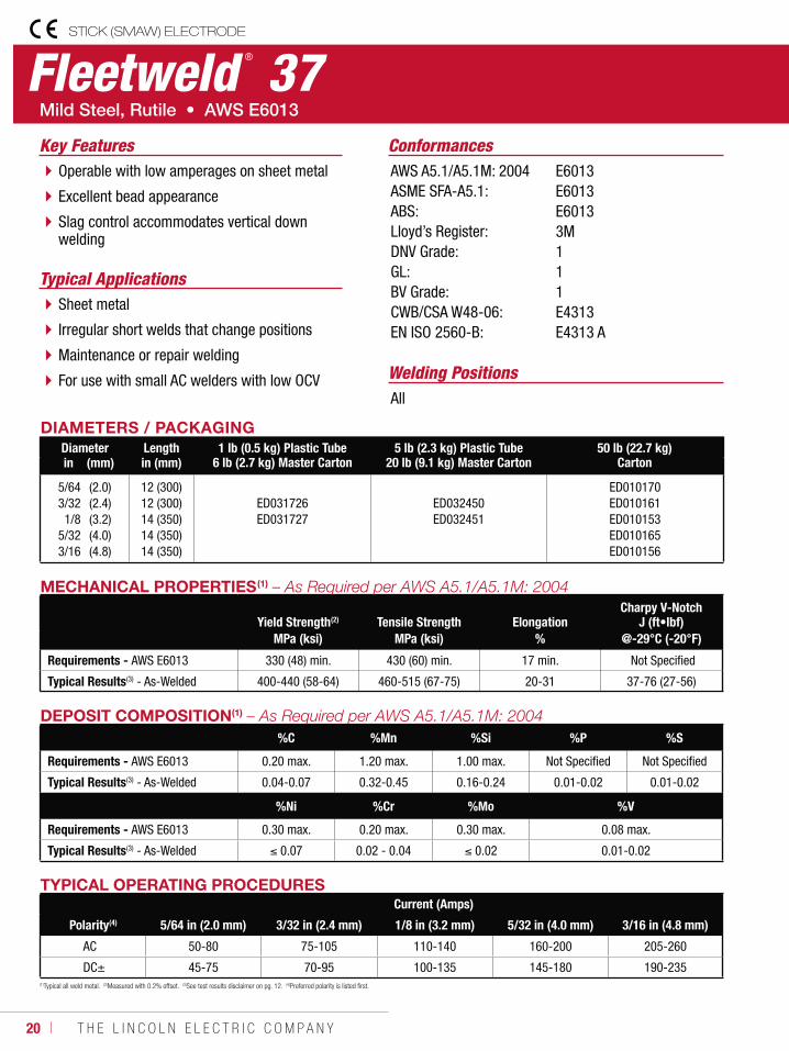
Fleetweld ® 37STICK (SMAW) ELECTRODE
Welding Positions
Typical Applications
All
Sheet metal
Irregular short welds that change positions
Maintenance or repair welding
For use with small AC welders with low OCV
Operable with low amperages on sheet metal
Excellent bead appearance
Slag control accommodates vertical down welding
ConformancesKey FeaturesAWS A5.1/A5.1M: 2004ASME SFA-A5.1:ABS:Lloyd’s Register:DNV Grade:GL:BV Grade:CWB/CSA W48-06:EN ISO 2560-B:
E6013E6013E60133M111E4313E4313 A
DIAMETERS / PACKAGINGDiameter Length 1 lb (0.5 kg) Plastic Tube
6 lb (2.7 kg) Master Carton5 lb (2.3 kg) Plastic Tube
20 lb (9.1 kg) Master Carton50 lb (22.7 kg)
Cartonin (mm) in (mm)
5/643/321/8
5/323/16
(2.0)(2.4)(3.2)(4.0)(4.8)
12 (300)12 (300)14 (350)14 (350)14 (350)
ED031726ED031727
ED032450ED032451
ED010170ED010161ED010153ED010165ED010156
MECHANICAL PROPERTIES(1)
Yield Strength(2) Tensile Strength ElongationCharpy V-Notch
J (ft•lbf)MPa (ksi) MPa (ksi) % @-29°C (-20°F)
Requirements - AWS E6013 330 (48) min. 430 (60) min. 17 min. Not Specified
Typical Results(3) - As-Welded 400-440 (58-64) 460-515 (67-75) 20-31 37-76 (27-56)
DEPOSIT COMPOSITION(1)
%C %Mn %Si %P %S
Requirements - AWS E6013 0.20 max. 1.20 max. 1.00 max. Not Specified Not Specified
Typical Results(3) - As-Welded 0.04-0.07 0.32-0.45 0.16-0.24 0.01-0.02 0.01-0.02
%Ni %Cr %Mo %V
Requirements - AWS E6013 0.30 max. 0.20 max. 0.30 max. 0.08 max.
Typical Results(3) - As-Welded 0.07 0.02 - 0.04 0.02 0.01-0.02
TYPICAL OPERATING PROCEDURESCurrent (Amps)
Polarity(4) 5/64 in (2.0 mm) 3/32 in (2.4 mm) 1/8 in (3.2 mm) 5/32 in (4.0 mm) 3/16 in (4.8 mm)
AC 50-80 75-105 110-140 160-200 205-260
DC± 45-75 70-95 100-135 145-180 190-235(1)Typical all weld metal. (2)Measured with 0.2% offset. (3)See test results disclaimer on pg. 12. (4)Preferred polarity is listed first.
W E L D I N G C O N S U M A B L E S C A T A L O G ı 21
STICK (SMAW) ELECTRODE
(1)Typical all weld metal. (2)Measured with 0.2% offset. (3)See test results disclaimer on pg. 12. (4)Preferred polarity is listed first.
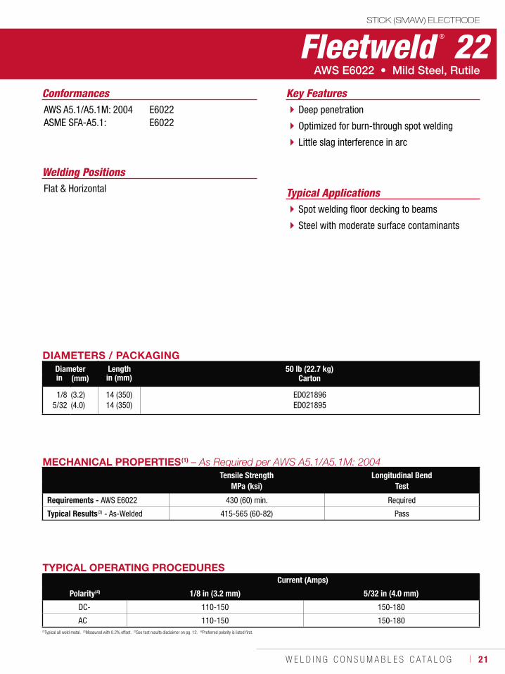
Fleetweld ® 22
Welding Positions
Typical ApplicationsFlat & Horizontal
Spot welding floor decking to beams
Steel with moderate surface contaminants
Deep penetration
Optimized for burn-through spot welding
Little slag interference in arc
Conformances Key FeaturesAWS A5.1/A5.1M: 2004ASME SFA-A5.1:
E6022E6022
DIAMETERS / PACKAGINGDiameter Length 50 lb (22.7 kg)
Cartonin (mm) in (mm)
1/85/32
(3.2)(4.0)
14 (350)14 (350)
ED021896ED021895
MECHANICAL PROPERTIES(1)
Tensile Strength Longitudinal BendMPa (ksi) Test
Requirements - AWS E6022 430 (60) min. Required
Typical Results(3) - As-Welded 415-565 (60-82) Pass
TYPICAL OPERATING PROCEDURESCurrent (Amps)
Polarity(4) 1/8 in (3.2 mm) 5/32 in (4.0 mm)
DC- 110-150 150-180
AC 110-150 150-180
22 ı T H E L I N C O L N E L E C T R I C C O M P A N Y
STICK (SMAW) ELECTRODE
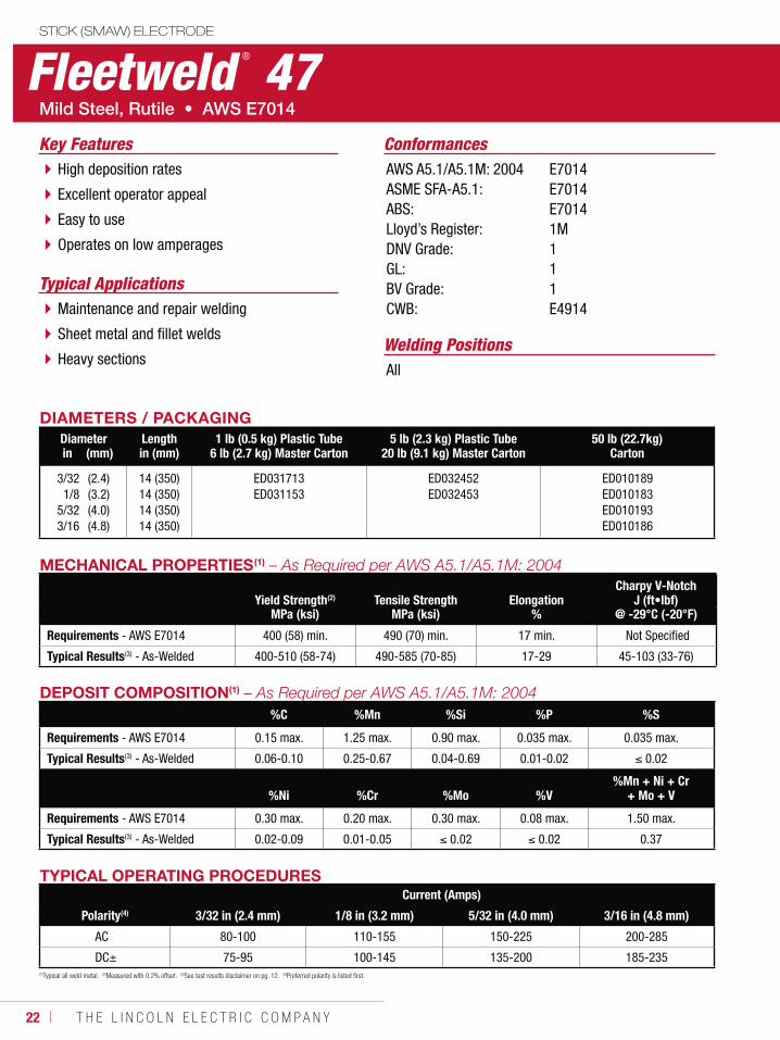
Fleetweld ® 47
Welding Positions
Typical Applications
All
Maintenance and repair welding
Sheet metal and fillet welds
Heavy sections
High deposition rates
Excellent operator appeal
Easy to use
Operates on low amperages
ConformancesKey FeaturesAWS A5.1/A5.1M: 2004ASME SFA-A5.1:ABS:Lloyd’s Register:DNV Grade:GL:BV Grade:CWB:
E7014E7014E70141M111E4914
DIAMETERS / PACKAGINGDiameter Length 1 lb (0.5 kg) Plastic Tube
6 lb (2.7 kg) Master Carton5 lb (2.3 kg) Plastic Tube
20 lb (9.1 kg) Master Carton50 lb (22.7kg)
Cartonin (mm) in (mm)
3/321/8
5/323/16
(2.4)(3.2)(4.0)(4.8)
14 (350)14 (350)14 (350)14 (350)
ED031713ED031153
ED032452ED032453
ED010189ED010183ED010193ED010186
TYPICAL OPERATING PROCEDURESCurrent (Amps)
Polarity(4) 3/32 in (2.4 mm) 1/8 in (3.2 mm) 5/32 in (4.0 mm) 3/16 in (4.8 mm)
AC 80-100 110-155 150-225 200-285
DC± 75-95 100-145 135-200 185-235
MECHANICAL PROPERTIES(1)
Yield Strength(2) Tensile Strength ElongationCharpy V-Notch
J (ft•lbf)MPa (ksi) MPa (ksi) % @ -29°C (-20°F)
Requirements - AWS E7014 400 (58) min. 490 (70) min. 17 min. Not Specified
Typical Results(3) - As-Welded 400-510 (58-74) 490-585 (70-85) 17-29 45-103 (33-76)
DEPOSIT COMPOSITION(1)
%C %Mn %Si %P %S
Requirements - AWS E7014 0.15 max. 1.25 max. 0.90 max. 0.035 max. 0.035 max.
Typical Results(3) - As-Welded 0.06-0.10 0.25-0.67 0.04-0.69 0.01-0.02 0.02
%Ni %Cr %Mo %V%Mn + Ni + Cr
+ Mo + V
Requirements - AWS E7014 0.30 max. 0.20 max. 0.30 max. 0.08 max. 1.50 max.
Typical Results(3) - As-Welded 0.02-0.09 0.01-0.05 0.02 0.02 0.37
(1)Typical all weld metal. (2)Measured with 0.2% offset. (3)See test results disclaimer on pg. 12. (4)Preferred polarity is listed first.
W E L D I N G C O N S U M A B L E S C A T A L O G ı 23
STICK (SMAW) ELECTRODE
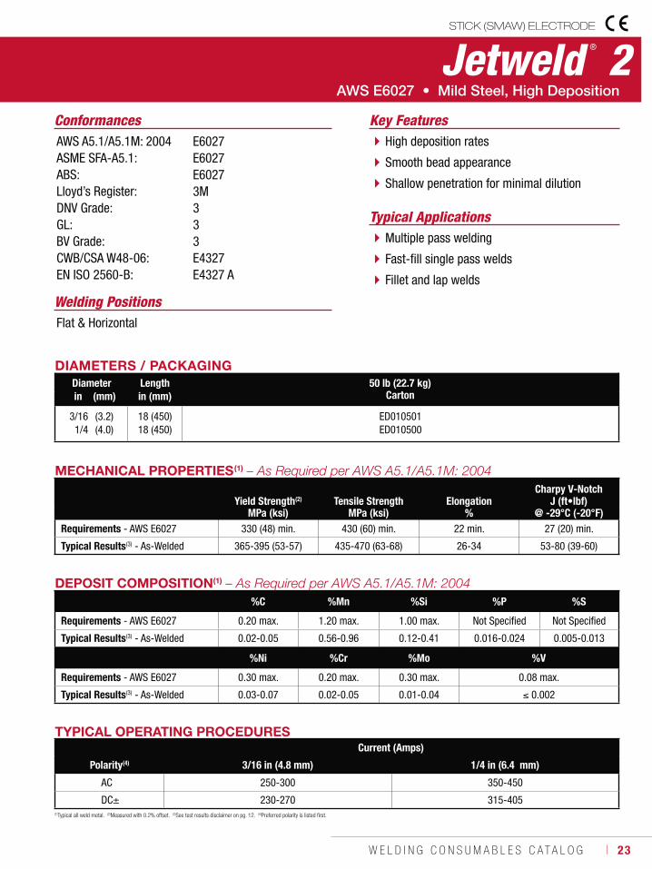
Jetweld ® 2
Welding Positions
Typical Applications
Flat & Horizontal
Multiple pass welding
Fast-fill single pass welds
Fillet and lap welds
High deposition rates
Smooth bead appearance
Shallow penetration for minimal dilution
Conformances Key FeaturesAWS A5.1/A5.1M: 2004ASME SFA-A5.1:ABS:Lloyd’s Register:DNV Grade:GL:BV Grade:CWB/CSA W48-06:EN ISO 2560-B:
E6027E6027E60273M333E4327E4327 A
DIAMETERS / PACKAGINGDiameter Length 50 lb (22.7 kg)
Cartonin (mm) in (mm)
3/161/4
(3.2)(4.0)
18 (450)18 (450)
ED010501ED010500
TYPICAL OPERATING PROCEDURESCurrent (Amps)
Polarity(4) 3/16 in (4.8 mm) 1/4 in (6.4 mm)
AC 250-300 350-450
DC± 230-270 315-405
MECHANICAL PROPERTIES(1)
Yield Strength(2) Tensile Strength ElongationCharpy V-Notch
J (ft•lbf)MPa (ksi) MPa (ksi) % @ -29°C (-20°F)
Requirements - AWS E6027 330 (48) min. 430 (60) min. 22 min. 27 (20) min.
Typical Results(3) - As-Welded 365-395 (53-57) 435-470 (63-68) 26-34 53-80 (39-60)
DEPOSIT COMPOSITION(1)
%C %Mn %Si %P %S
Requirements - AWS E6027 0.20 max. 1.20 max. 1.00 max. Not Specified Not Specified
Typical Results(3) - As-Welded 0.02-0.05 0.56-0.96 0.12-0.41 0.016-0.024 0.005-0.013
%Ni %Cr %Mo %V
Requirements - AWS E6027 0.30 max. 0.20 max. 0.30 max. 0.08 max.
Typical Results(3) - As-Welded 0.03-0.07 0.02-0.05 0.01-0.04 0.002
(1)Typical all weld metal. (2)Measured with 0.2% offset. (3)See test results disclaimer on pg. 12. (4)Preferred polarity is listed first.
24 ı T H E L I N C O L N E L E C T R I C C O M P A N Y
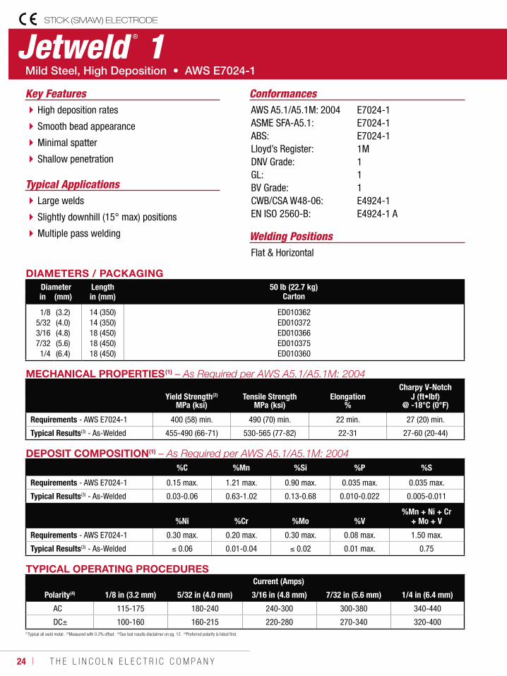
Jetweld ® 1STICK (SMAW) ELECTRODE
Welding Positions
Typical Applications
Flat & Horizontal
Large welds
Slightly downhill (15° max) positions
Multiple pass welding
High deposition rates
Smooth bead appearance
Minimal spatter
Shallow penetration
ConformancesKey FeaturesAWS A5.1/A5.1M: 2004ASME SFA-A5.1:ABS:Lloyd’s Register:DNV Grade:GL:BV Grade:CWB/CSA W48-06:EN ISO 2560-B:
E7024-1E7024-1E7024-11M111E4924-1E4924-1 A
DIAMETERS / PACKAGINGDiameter Length 50 lb (22.7 kg)
Cartonin (mm) in (mm)
1/85/323/167/321/4
(3.2)(4.0)(4.8)(5.6)(6.4)
14 (350)14 (350)18 (450)18 (450)18 (450)
ED010362ED010372ED010366ED010375ED010360
TYPICAL OPERATING PROCEDURESCurrent (Amps)
Polarity(4) 1/8 in (3.2 mm) 5/32 in (4.0 mm) 3/16 in (4.8 mm) 7/32 in (5.6 mm) 1/4 in (6.4 mm)
AC 115-175 180-240 240-300 300-380 340-440
DC± 100-160 160-215 220-280 270-340 320-400
MECHANICAL PROPERTIES(1)
Yield Strength(2) Tensile Strength ElongationCharpy V-Notch
J (ft•lbf)MPa (ksi) MPa (ksi) % @ -18°C (0°F)
Requirements - AWS E7024-1 400 (58) min. 490 (70) min. 22 min. 27 (20) min.
Typical Results(3) - As-Welded 455-490 (66-71) 530-565 (77-82) 22-31 27-60 (20-44)
DEPOSIT COMPOSITION(1)
%C %Mn %Si %P %S
Requirements - AWS E7024-1 0.15 max. 1.21 max. 0.90 max. 0.035 max. 0.035 max.
Typical Results(3) - As-Welded 0.03-0.06 0.63-1.02 0.13-0.68 0.010-0.022 0.005-0.011
%Ni %Cr %Mo %V%Mn + Ni + Cr
+ Mo + V
Requirements - AWS E7024-1 0.30 max. 0.20 max. 0.30 max. 0.08 max. 1.50 max.
Typical Results(3) - As-Welded 0.06 0.01-0.04 0.02 0.01 max. 0.75
(1)Typical all weld metal. (2)Measured with 0.2% offset. (3)See test results disclaimer on pg. 12. (4)Preferred polarity is listed first.
W E L D I N G C O N S U M A B L E S C A T A L O G ı 25
(1)Typical all weld metal. (2)Measured with 0.2% offset. (3)See test results disclaimer on pg. 12. (4)Preferred polarity is listed first. (5)DC- for root pass on pipe; DC± for general welding.
* These part number are Made-to-Oder (MTO).
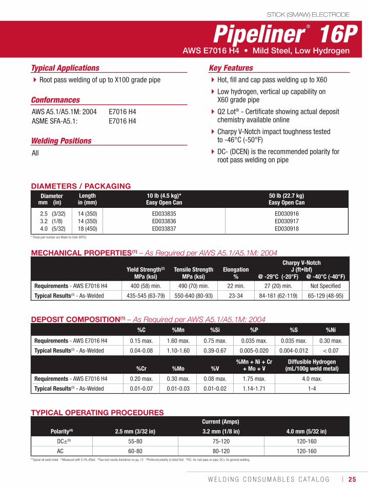
Pipeliner ® 16PSTICK (SMAW) ELECTRODE
Welding Positions
Typical Applications
All
Root pass welding of up to X100 grade pipe Hot, fill and cap pass welding up to X60
Low hydrogen, vertical up capability on X60 grade pipe
Q2 Lot® - Certificate showing actual deposit chemistry available online
Charpy V-Notch impact toughness tested to -46°C (-50°F)
DC- (DCEN) is the recommended polarity for root pass welding on pipe
Conformances
AWS E7016 H4 • Mild Steel, Low Hydrogen
Key Features
AWS A5.1/A5.1M: 2004ASME SFA-A5.1:
E7016 H4E7016 H4
DIAMETERS / PACKAGINGDiameter Length 10 lb (4.5 kg)*
Easy Open Can50 lb (22.7 kg)Easy Open Canmm (in) in (mm)
2.53.24.0
(3/32)(1/8)(5/32)
14 (350)14 (350)18 (450)
ED033835 ED033836 ED033837
ED030916ED030917ED030918
TYPICAL OPERATING PROCEDURESCurrent (Amps)
Polarity(4) 2.5 mm (3/32 in) 3.2 mm (1/8 in) 4.0 mm (5/32 in)
DC±(5) 55-80 75-120 120-160
AC 60-80 80-120 120-160
MECHANICAL PROPERTIES(1) – As Required per AWS A5.1/A5.1M: 2004
Yield Strength(2) Tensile Strength ElongationCharpy V-Notch
J (ft•lbf)MPa (ksi) MPa (ksi) % @ -29°C (-20°F) @ -40°C (-40°F)
Requirements - AWS E7016 H4 400 (58) min. 490 (70) min. 22 min. 27 (20) min. Not Specified
Typical Results(3) - As-Welded 435-545 (63-79) 550-640 (80-93) 23-34 84-161 (62-119) 65-129 (48-95)
DEPOSIT COMPOSITION(1) – As Required per AWS A5.1/A5.1M: 2004%C %Mn %Si %P %S %Ni
Requirements - AWS E7016 H4 0.15 max. 1.60 max. 0.75 max. 0.035 max. 0.035 max. 0.30 max.
Typical Results(3) - As-Welded 0.04-0.08 1.10-1.60 0.39-0.67 0.005-0.020 0.004-0.012 < 0.07
%Cr %Mo %V%Mn + Ni + Cr
+ Mo + VDiffusible Hydrogen
(mL/100g weld metal)
Requirements - AWS E7016 H4 0.20 max. 0.30 max. 0.08 max. 1.75 max. 4.0 max.
Typical Results(3) - As-Welded 0.01-0.07 0.01-0.03 0.01-0.02 1.14-1.71 1-4
26 ı T H E L I N C O L N E L E C T R I C C O M P A N Y
STICK (SMAW) ELECTRODE
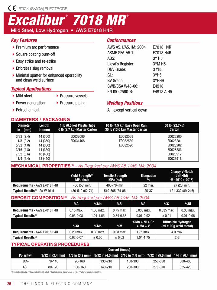
Excalibur ® 7018 MR ®
Welding Positions
Typical Applications
All, except vertical down
Mild steel
Power generation
Petrochemical
Pressure vessels
Pressure piping
Premium arc performance
Square coating burn-off
Easy strike and re-strike
Effortless slag removal
Minimal spatter for enhanced operability and clean weld surface
ConformancesKey FeaturesAWS A5.1/A5.1M: 2004ASME SFA-A5.1:ABS:Lloyd’s Register:DNV Grade:GL:BV Grade:CWB/CSA W48-06:EN ISO 2560-B:
E7018 H4RE7018 H4R3Y H53YM H53 YH53YH53YHHHE4918E4918 A H5
DIAMETERS / PACKAGINGDiameter Length 1 lb (0.5 kg) Plastic Tube
6 lb (2.7 kg) Master Carton10 lb (4.5 kg) Easy Open Can30 lb (13.6 kg) Master Carton
50 lb (22.7kg)Cartonin (mm) in (mm)
3/321/8
5/323/167/321/4
(2.4)(3.2)(4.0)(4.8)(5.6)(6.4)
14 (350)14 (350)14 (350)14 (350)18 (450)18 (450)
ED032086ED031468
ED032588ED032589ED032590
ED028280ED028281ED028282ED028283ED028917ED028918
TYPICAL OPERATING PROCEDURESCurrent (Amps)
Polarity(4) 3/32 in (2.4 mm) 1/8 in (3.2 mm) 5/32 in (4.0 mm) 3/16 in (4.8 mm) 7/32 in (5.6 mm) 1/4 in (6.4 mm)
DC+ 70-110 90-160 130-210 180-300 250-330 300-400
AC 80-120 100-160 140-210 200-300 270-370 325-420
MECHANICAL PROPERTIES(1)
Yield Strength(2) Tensile Strength ElongationCharpy V-Notch
J (ft•lbf)MPa (ksi) MPa (ksi) % @ -29°C (-20°F)
Requirements - AWS E7018 H4R 400 (58) min. 490 (70) min. 22 min. 27 (20) min.
Typical Results(3) - As-Welded 430-510 (62-74) 510-605 (74-88) 25-37 121-332 (89-246)
DEPOSIT COMPOSITION(1)
%C %Mn %Si %P %S %Ni
Requirements - AWS E7018 H4R 0.15 max. 1.60 max. 0.75 max. 0.035 max. 0.035 max. 0.30 max.
Typical Results(3) 0.03-0.08 1.01-1.55 0.34-0.68 0.01-0.02 0.01 0.01-0.06
%Cr %Mo %V%Mn + Ni + Cr
+ Mo + VDiffusible Hydrogen
(mL/100g weld metal)
Requirements - AWS E7018 H4R 0.20 max. 0.30 max. 0.08 max. 1.75 max. 4.0 max.
Typical Results(3) 0.02-0.07 0.05 0.02 1.04-1.75 2-3
(1)Typical all weld metal. (2)Measured with 0.2% offset. (3)See test results disclaimer on pg. 12. (4)Preferred polarity is listed first.
W E L D I N G C O N S U M A B L E S C A T A L O G ı 27
STICK (SMAW) ELECTRODE
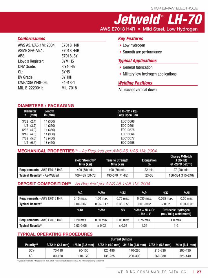
Jetweld ® LH-70
Welding Positions
Typical Applications
All, except vertical down
General fabrication
Military low hydrogen applications
Low hydrogen
Smooth arc performance
Conformances Key FeaturesAWS A5.1/A5.1M: 2004ASME SFA-A5.1:ABS:Lloyd’s Register:DNV Grade:GL:BV Grade:CWB/CSA W48-06:MIL-E-22200/1:
E7018 H4RE7018 H4RE7018, 3Y3YM H53 Y40H53YH53YHHHE4918-1MIL-7018
DIAMETERS / PACKAGINGDiameter Length 50 lb (22.7 kg)
Easy Open Canin (mm) in (mm)
3/321/8
5/323/167/321/4
(2.4)(3.2)(4.0)(4.8)(5.6)(6.4)
14 (350)14 (350)14 (350)14 (350)18 (450)18 (450)
ED010568ED010561ED010575ED010564ED010577ED010558
(1)Typical all weld metal. (2)Measured with 0.2% offset. (3)See test results disclaimer on pg. 12. (4)Preferred polarity is listed first.
TYPICAL OPERATING PROCEDURESCurrent (Amps)
Polarity(4) 3/32 in (2.4 mm) 1/8 in (3.2 mm) 5/32 in (4.0 mm) 3/16 in (4.8 mm) 7/32 in (5.6 mm) 1/4 in (6.4 mm)
DC+ 70-110 90-150 120-190 170-280 210-330 290-430
AC 80-120 110-170 135-225 200-300 260-380 325-440
MECHANICAL PROPERTIES(1)
Yield Strength(2) Tensile Strength ElongationCharpy V-Notch
J (ft•lbf)MPa (ksi) MPa (ksi) % @ -29°C (-20°F)
Requirements - AWS E7018 H4R 400 (58) min. 490 (70) min. 22 min. 27 (20) min.
Typical Results(3) - As-Welded 400-485 (58-70) 490-570 (71-83) 23-36 156-334 (115-246)
DEPOSIT COMPOSITION(1)
%C %Mn %Si %P %S %Ni
Requirements - AWS E7018 H4R 0.15 max. 1.60 max. 0.75 max. 0.035 max. 0.035 max. 0.30 max.
Typical Results(3) 0.04-0.07 0.95-1.17 0.30-0.53 0.01-0.02 0.02 0.01-0.05
%Cr %Mo %V %Mn + Ni + Cr + Mo + V
Diffusible Hydrogen(mL/100g weld metal)
Requirements - AWS E7018 H4R 0.20 max. 0.30 max. 0.08 max. 1.75 max. 4.0 max.
Typical Results(3) 0.03-0.06 0.02 0.02 1.05 1-2
28 ı T H E L I N C O L N E L E C T R I C C O M P A N Y
STICK (SMAW) ELECTRODE
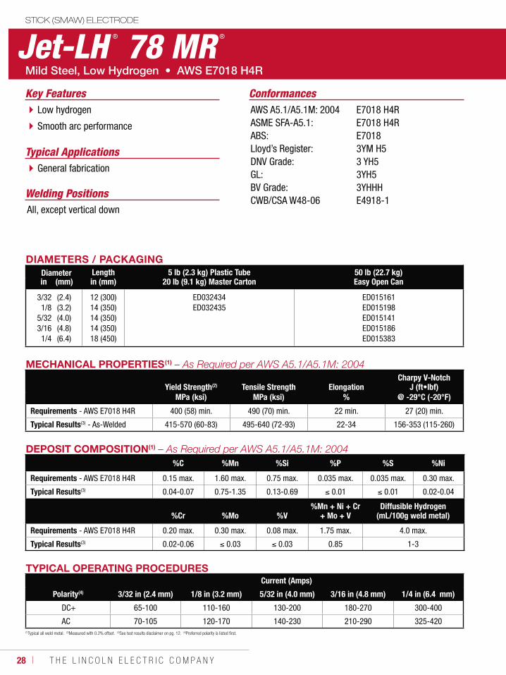
Jet-LH ® 78 MR ®
Welding Positions
Typical Applications
All, except vertical down
General fabrication
Low hydrogen
Smooth arc performance
ConformancesKey FeaturesAWS A5.1/A5.1M: 2004ASME SFA-A5.1:ABS:Lloyd’s Register:DNV Grade:GL:BV Grade:CWB/CSA W48-06
E7018 H4RE7018 H4RE70183YM H53 YH53YH53YHHHE4918-1
DIAMETERS / PACKAGINGDiameter Length 5 lb (2.3 kg) Plastic Tube
20 lb (9.1 kg) Master Carton50 lb (22.7 kg)Easy Open Canin (mm) in (mm)
3/321/8
5/323/161/4
(2.4)(3.2)(4.0)(4.8)(6.4)
12 (300)14 (350)14 (350)14 (350)18 (450)
ED032434ED032435
ED015161ED015198ED015141ED015186ED015383
MECHANICAL PROPERTIES(1)
Yield Strength(2) Tensile Strength ElongationCharpy V-Notch
J (ft•lbf)MPa (ksi) MPa (ksi) % @ -29°C (-20°F)
Requirements - AWS E7018 H4R 400 (58) min. 490 (70) min. 22 min. 27 (20) min.
Typical Results(3) - As-Welded 415-570 (60-83) 495-640 (72-93) 22-34 156-353 (115-260)
TYPICAL OPERATING PROCEDURESCurrent (Amps)
Polarity(4) 3/32 in (2.4 mm) 1/8 in (3.2 mm) 5/32 in (4.0 mm) 3/16 in (4.8 mm) 1/4 in (6.4 mm)
DC+ 65-100 110-160 130-200 180-270 300-400
AC 70-105 120-170 140-230 210-290 325-420
DEPOSIT COMPOSITION(1)
%C %Mn %Si %P %S %Ni
Requirements - AWS E7018 H4R 0.15 max. 1.60 max. 0.75 max. 0.035 max. 0.035 max. 0.30 max.
Typical Results(3) 0.04-0.07 0.75-1.35 0.13-0.69 0.01 0.01 0.02-0.04
%Cr %Mo %V%Mn + Ni + Cr
+ Mo + VDiffusible Hydrogen
(mL/100g weld metal)
Requirements - AWS E7018 H4R 0.20 max. 0.30 max. 0.08 max. 1.75 max. 4.0 max.
Typical Results(3) 0.02-0.06 0.03 0.03 0.85 1-3
(1)Typical all weld metal. (2)Measured with 0.2% offset. (3)See test results disclaimer on pg. 12. (4)Preferred polarity is listed first.
W E L D I N G C O N S U M A B L E S C A T A L O G ı 29
STICK (SMAW) ELECTRODE
(1)Typical all weld metal. (2)Measured with 0.2% offset. (3)See test results disclaimer on pg. 12. (4)Preferred polarity is listed first.
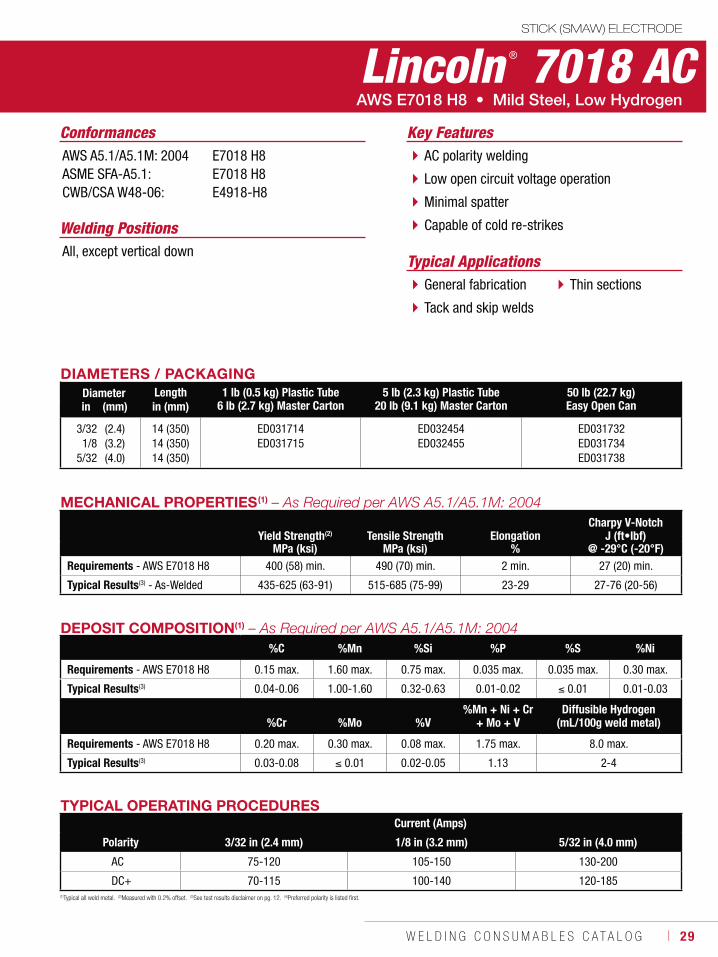
Lincoln ® 7018 AC
Welding Positions
Typical ApplicationsAll, except vertical down
General fabrication
Tack and skip welds
Thin sections
AC polarity welding
Low open circuit voltage operation
Minimal spatter
Capable of cold re-strikes
Conformances Key FeaturesAWS A5.1/A5.1M: 2004ASME SFA-A5.1:CWB/CSA W48-06:
E7018 H8E7018 H8E4918-H8
DIAMETERS / PACKAGINGDiameter Length 1 lb (0.5 kg) Plastic Tube
6 lb (2.7 kg) Master Carton5 lb (2.3 kg) Plastic Tube
20 lb (9.1 kg) Master Carton50 lb (22.7 kg)Easy Open Canin (mm) in (mm)
3/321/8
5/32
(2.4)(3.2)(4.0)
14 (350)14 (350)14 (350)
ED031714ED031715
ED032454ED032455
ED031732ED031734ED031738
TYPICAL OPERATING PROCEDURESCurrent (Amps)
Polarity 3/32 in (2.4 mm) 1/8 in (3.2 mm) 5/32 in (4.0 mm)
AC 75-120 105-150 130-200
DC+ 70-115 100-140 120-185
MECHANICAL PROPERTIES(1)
Yield Strength(2) Tensile Strength ElongationCharpy V-Notch
J (ft•lbf)MPa (ksi) MPa (ksi) % @ -29°C (-20°F)
Requirements - AWS E7018 H8 400 (58) min. 490 (70) min. 2 min. 27 (20) min.
Typical Results(3) - As-Welded 435-625 (63-91) 515-685 (75-99) 23-29 27-76 (20-56)
DEPOSIT COMPOSITION(1)
%C %Mn %Si %P %S %Ni
Requirements - AWS E7018 H8 0.15 max. 1.60 max. 0.75 max. 0.035 max. 0.035 max. 0.30 max.
Typical Results(3) 0.04-0.06 1.00-1.60 0.32-0.63 0.01-0.02 0.01 0.01-0.03
%Cr %Mo %V%Mn + Ni + Cr
+ Mo + VDiffusible Hydrogen
(mL/100g weld metal)
Requirements - AWS E7018 H8 0.20 max. 0.30 max. 0.08 max. 1.75 max. 8.0 max.
Typical Results(3) 0.03-0.08 0.01 0.02-0.05 1.13 2-4
30 ı T H E L I N C O L N E L E C T R I C C O M P A N Y
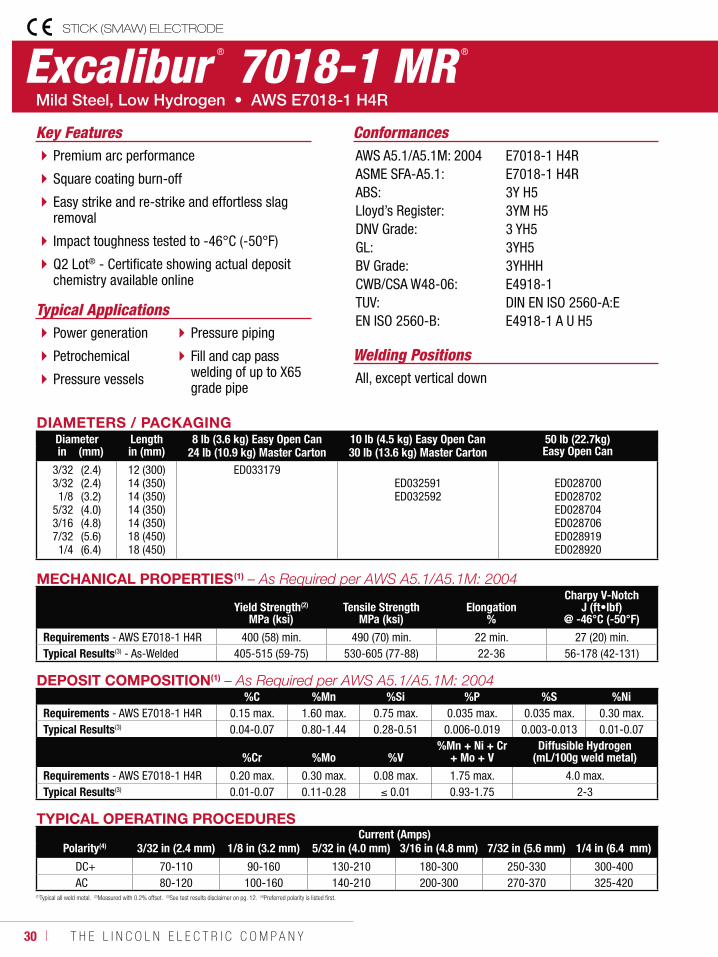
Excalibur ® 7018-1 MR ®
STICK (SMAW) ELECTRODE
Welding Positions
Typical Applications
All, except vertical down
Power generation
Petrochemical
Pressure vessels
Pressure piping
Fill and cap pass welding of up to X65 grade pipe
Premium arc performance
Square coating burn-off
Easy strike and re-strike and effortless slag removal
Impact toughness tested to -46°C (-50°F)
Q2 Lot® - Certificate showing actual deposit chemistry available online
ConformancesKey FeaturesAWS A5.1/A5.1M: 2004ASME SFA-A5.1:ABS:Lloyd’s Register:DNV Grade:GL:BV Grade:CWB/CSA W48-06:TUV:EN ISO 2560-B:
E7018-1 H4RE7018-1 H4R3Y H53YM H53 YH53YH53YHHHE4918-1DIN EN ISO 2560-A:EE4918-1 A U H5
DIAMETERS / PACKAGINGDiameter Length 8 lb (3.6 kg) Easy Open Can
24 lb (10.9 kg) Master Carton10 lb (4.5 kg) Easy Open Can30 lb (13.6 kg) Master Carton
50 lb (22.7kg)Easy Open Canin (mm) in (mm)
3/323/321/8
5/323/167/321/4
(2.4)(2.4)(3.2)(4.0)(4.8)(5.6)(6.4)
12 (300)14 (350)14 (350)14 (350)14 (350)18 (450)18 (450)
ED033179ED032591ED032592
ED028700ED028702ED028704ED028706ED028919ED028920
TYPICAL OPERATING PROCEDURESCurrent (Amps)
Polarity(4) 3/32 in (2.4 mm) 1/8 in (3.2 mm) 5/32 in (4.0 mm) 3/16 in (4.8 mm) 7/32 in (5.6 mm) 1/4 in (6.4 mm)
DC+ 70-110 90-160 130-210 180-300 250-330 300-400AC 80-120 100-160 140-210 200-300 270-370 325-420
MECHANICAL PROPERTIES(1)
Yield Strength(2)
MPa (ksi)Tensile Strength
MPa (ksi)Elongation
%
Charpy V-NotchJ (ft•lbf)
@ -46°C (-50°F)
Requirements - AWS E7018-1 H4R 400 (58) min. 490 (70) min. 22 min. 27 (20) min.Typical Results(3) - As-Welded 405-515 (59-75) 530-605 (77-88) 22-36 56-178 (42-131)
DEPOSIT COMPOSITION(1)
%C %Mn %Si %P %S %NiRequirements - AWS E7018-1 H4R 0.15 max. 1.60 max. 0.75 max. 0.035 max. 0.035 max. 0.30 max.Typical Results(3) 0.04-0.07 0.80-1.44 0.28-0.51 0.006-0.019 0.003-0.013 0.01-0.07
%Cr %Mo %V%Mn + Ni + Cr
+ Mo + VDiffusible Hydrogen
(mL/100g weld metal)
Requirements - AWS E7018-1 H4R 0.20 max. 0.30 max. 0.08 max. 1.75 max. 4.0 max.Typical Results(3) 0.01-0.07 0.11-0.28 0.01 0.93-1.75 2-3
(1)Typical all weld metal. (2)Measured with 0.2% offset. (3)See test results disclaimer on pg. 12. (4)Preferred polarity is listed first.
W E L D I N G C O N S U M A B L E S C A T A L O G ı 31
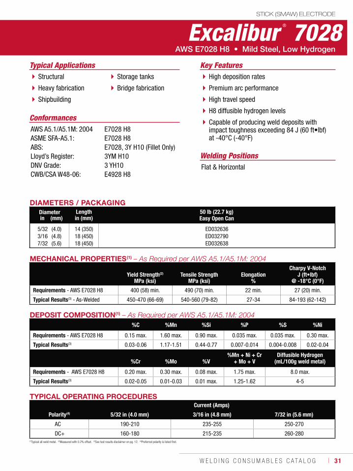
Excalibur ® 7028STICK (SMAW) ELECTRODE
Welding Positions
Typical Applications
Flat & Horizontal
Structural
Heavy fabrication
Shipbuilding
Storage tanks
Bridge fabrication
High deposition rates
Premium arc performance
High travel speed
H8 diffusible hydrogen levels
Capable of producing weld deposits with impact toughness exceeding 84 J (60 ft•lbf) at -40°C (-40°F)
Conformances
Key Features
AWS A5.1/A5.1M: 2004ASME SFA-A5.1:ABS:Lloyd’s Register:DNV Grade:CWB/CSA W48-06:
E7028 H8E7028 H8E7028, 3Y H10 (Fillet Only)3YM H103 YH10E4928 H8
DIAMETERS / PACKAGINGDiameter Length 50 lb (22.7 kg)
Easy Open Canin (mm) in (mm)
5/323/167/32
(4.0)(4.8)(5.6)
14 (350)18 (450)18 (450)
ED032636ED032790ED032638
(1)Typical all weld metal. (2)Measured with 0.2% offset. (3)See test results disclaimer on pg. 12. (4)Preferred polarity is listed first.
TYPICAL OPERATING PROCEDURESCurrent (Amps)
Polarity(4) 5/32 in (4.0 mm) 3/16 in (4.8 mm) 7/32 in (5.6 mm)
AC 190-210 235-255 250-270
DC+ 160-180 215-235 260-280
MECHANICAL PROPERTIES(1)
Yield Strength(2) Tensile Strength ElongationCharpy V-Notch
J (ft•lbf)MPa (ksi) MPa (ksi) % @ -18°C (0°F)
Requirements - AWS E7028 H8 400 (58) min. 490 (70) min. 22 min. 27 (20) min.
Typical Results(3) - As-Welded 450-470 (66-69) 540-560 (79-82) 27-34 84-193 (62-142)
DEPOSIT COMPOSITION(1)
%C %Mn %Si %P %S %Ni
Requirements - AWS E7028 H8 0.15 max. 1.60 max. 0.90 max. 0.035 max. 0.035 max. 0.30 max.
Typical Results(3) 0.03-0.06 1.17-1.51 0.44-0.77 0.007-0.014 0.004-0.008 0.02-0.04
%Cr %Mo %V%Mn + Ni + Cr
+ Mo + VDiffusible Hydrogen
(mL/100g weld metal)
Requirements - AWS E7028 H8 0.20 max. 0.30 max. 0.08 max. 1.75 max. 8.0 max.
Typical Results(3) 0.02-0.05 0.01-0.03 0.01 max. 1.25-1.62 4-5
32 ı T H E L I N C O L N E L E C T R I C C O M P A N Y
STICK (SMAW) ELECTRODE
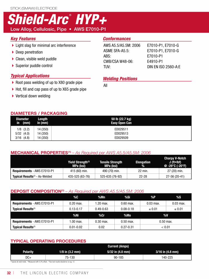
Shield-Arc ® HYP+
Welding PositionsTypical Applications
AllRoot pass welding of up to X80 grade pipe
Hot, fill and cap pass of up to X65 grade pipe
Vertical down welding
Light slag for minimal arc interference
Deep penetration
Clean, visible weld puddle
Superior puddle control
ConformancesKey FeaturesAWS A5.5/A5.5M: 2006ASME SFA-A5.5:ABS:CWB/CSA W48-06:TUV:
E7010-P1, E7010-GE7010-P1, E7010-GE7010-P1E4910-P1DIN EN ISO 2560-A:E
DIAMETERS / PACKAGINGDiameter Length 50 lb (22.7 kg)
Easy Open Canin (mm) in (mm)
1/85/323/16
(3.2)(4.0)(4.8)
14 (350)14 (350)14 (350)
ED029511ED029513ED029509
TYPICAL OPERATING PROCEDURESCurrent (Amps)
Polarity 1/8 in (3.2 mm) 5/32 in (4.0 mm) 3/16 in (4.8 mm)
DC+ 75-130 90-185 140-225
MECHANICAL PROPERTIES(1)
Yield Strength(2) Tensile Strength ElongationCharpy V-Notch
J (ft•lbf)MPa (ksi) MPa (ksi) % @ -29°C (-20°F)
Requirements - AWS E7010-P1 415 (60) min. 490 (70) min. 22 min. 27 (20) min.
Typical Results(3) - As-Welded 435-525 (63-76) 525-635 (76-92) 22-28 27-56 (20-41)
DEPOSIT COMPOSITION(1)
%C %Mn %Si %P %S
Requirements - AWS E7010-P1 0.20 max. 1.20 max. 0.60 max. 0.03 max. 0.03 max.
Typical Results(3) 0.13-0.17 0.49-0.63 0.08-0.18 0.01 0.01
%Ni %Cr %Mo %V
Requirements - AWS E7010-P1 1.00 max. 0.30 max. 0.50 max. 0.50 max.
Typical Results(3) 0.01-0.02 0.02 0.27-0.31 < 0.01
(1)Typical all weld metal. (2)Measured with 0.2% offset. (3)See test results disclaimer on pg. 12.
W E L D I N G C O N S U M A B L E S C A T A L O G ı 33
STICK (SMAW) ELECTRODE
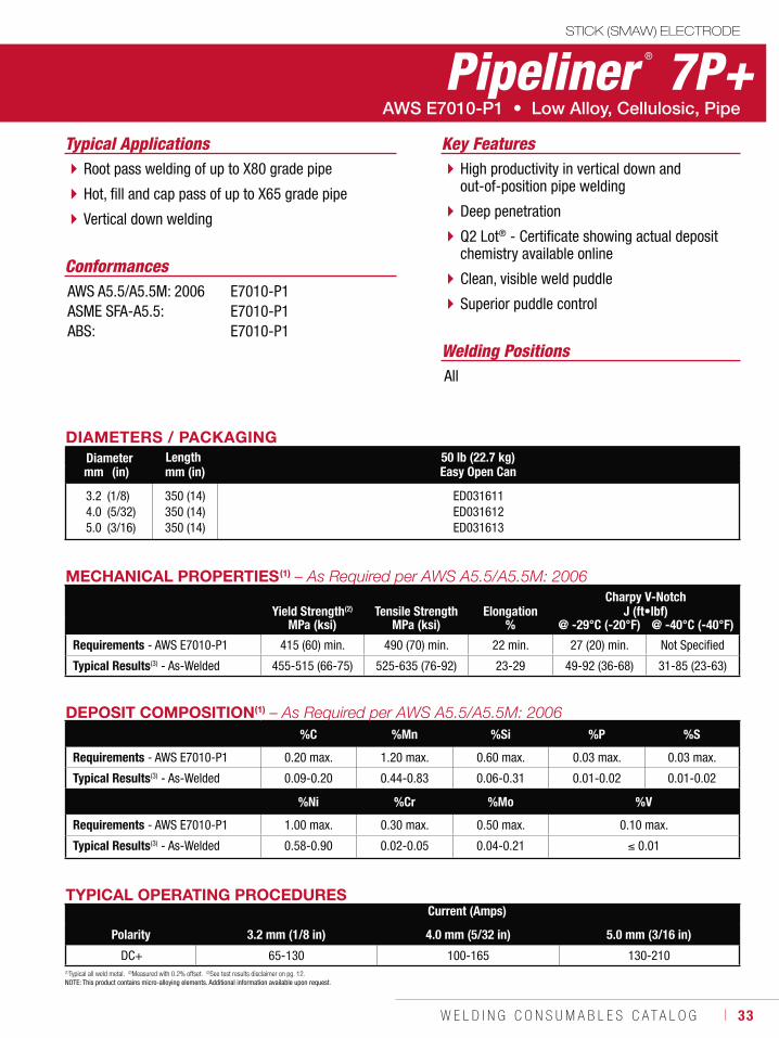
Pipeliner ® 7P+
Welding Positions
Typical Applications
All
Root pass welding of up to X80 grade pipe
Hot, fill and cap pass of up to X65 grade pipe
Vertical down welding
High productivity in vertical down and out-of-position pipe welding
Deep penetration
Q2 Lot® - Certificate showing actual deposit chemistry available online
Clean, visible weld puddle
Superior puddle control
Conformances
Key Features
AWS A5.5/A5.5M: 2006ASME SFA-A5.5:ABS:
E7010-P1E7010-P1E7010-P1
DIAMETERS / PACKAGINGDiameter Length 50 lb (22.7 kg)
Easy Open Canmm (in) mm (in)
3.24.05.0
(1/8)(5/32)(3/16)
350 (14)350 (14)350 (14)
ED031611ED031612ED031613
TYPICAL OPERATING PROCEDURESCurrent (Amps)
Polarity 3.2 mm (1/8 in) 4.0 mm (5/32 in) 5.0 mm (3/16 in)
DC+ 65-130 100-165 130-210
MECHANICAL PROPERTIES(1)
Yield Strength(2) Tensile Strength ElongationCharpy V-Notch
J (ft•lbf)MPa (ksi) MPa (ksi) % @ -29°C (-20°F) @ -40°C (-40°F)
Requirements - AWS E7010-P1 415 (60) min. 490 (70) min. 22 min. 27 (20) min. Not Specified
Typical Results(3) - As-Welded 455-515 (66-75) 525-635 (76-92) 23-29 49-92 (36-68) 31-85 (23-63)
DEPOSIT COMPOSITION(1)
%C %Mn %Si %P %S
Requirements - AWS E7010-P1 0.20 max. 1.20 max. 0.60 max. 0.03 max. 0.03 max.
Typical Results(3) - As-Welded 0.09-0.20 0.44-0.83 0.06-0.31 0.01-0.02 0.01-0.02
%Ni %Cr %Mo %V
Requirements - AWS E7010-P1 1.00 max. 0.30 max. 0.50 max. 0.10 max.
Typical Results(3) - As-Welded 0.58-0.90 0.02-0.05 0.04-0.21 0.01
(1)Typical all weld metal. (2)Measured with 0.2% offset. (3)See test results disclaimer on pg. 12.NOTE: This product contains micro-alloying elements. Additional information available upon request.
34 ı T H E L I N C O L N E L E C T R I C C O M P A N Y
STICK (SMAW) ELECTRODE
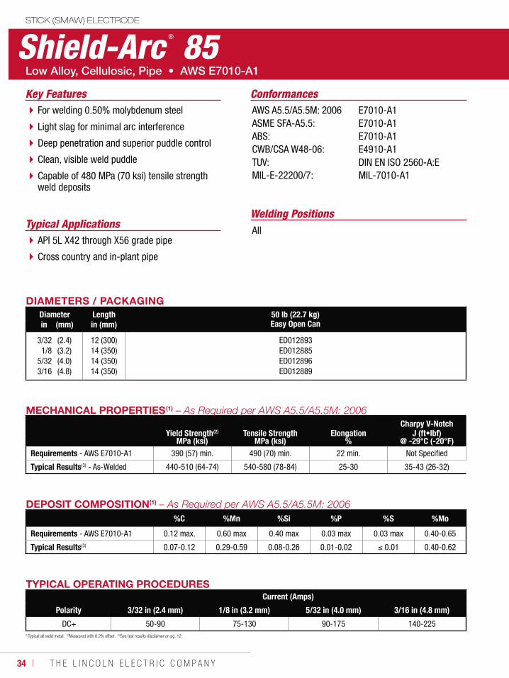
Shield-Arc ® 85
Welding PositionsTypical Applications
AllAPI 5L X42 through X56 grade pipe
Cross country and in-plant pipe
For welding 0.50% molybdenum steel
Light slag for minimal arc interference
Deep penetration and superior puddle control
Clean, visible weld puddle
Capable of 480 MPa (70 ksi) tensile strength weld deposits
ConformancesKey FeaturesAWS A5.5/A5.5M: 2006ASME SFA-A5.5:ABS:CWB/CSA W48-06:TUV:MIL-E-22200/7:
E7010-A1E7010-A1E7010-A1E4910-A1DIN EN ISO 2560-A:EMIL-7010-A1
DIAMETERS / PACKAGINGDiameter Length 50 lb (22.7 kg)
Easy Open Canin (mm) in (mm)
3/321/8
5/323/16
(2.4)(3.2)(4.0)(4.8)
12 (300)14 (350)14 (350)14 (350)
ED012893ED012885ED012896ED012889
DEPOSIT COMPOSITION(1)
%C %Mn %Si %P %S %Mo
Requirements - AWS E7010-A1 0.12 max. 0.60 max 0.40 max 0.03 max 0.03 max 0.40-0.65
Typical Results(3) 0.07-0.12 0.29-0.59 0.08-0.26 0.01-0.02 0.01 0.40-0.62
TYPICAL OPERATING PROCEDURESCurrent (Amps)
Polarity 3/32 in (2.4 mm) 1/8 in (3.2 mm) 5/32 in (4.0 mm) 3/16 in (4.8 mm)
DC+ 50-90 75-130 90-175 140-225(1)Typical all weld metal. (2)Measured with 0.2% offset. (3)See test results disclaimer on pg. 12.
MECHANICAL PROPERTIES(1)
Yield Strength(2) Tensile Strength ElongationCharpy V-Notch
J (ft•lbf)MPa (ksi) MPa (ksi) % @ -29°C (-20°F)
Requirements - AWS E7010-A1 390 (57) min. 490 (70) min. 22 min. Not Specified
Typical Results(3) - As-Welded 440-510 (64-74) 540-580 (78-84) 25-30 35-43 (26-32)

W E L D I N G C O N S U M A B L E S C A T A L O G ı 35
STICK (SMAW) ELECTRODE
Shield-Arc ® 70+
Welding PositionsTypical Applications
AllRelatively high silicon pipe
API 5L X56 through X70 grade pipe
Cross country and in-plant pipe
Light slag for minimal arc interference
Deep penetration
Clean, visible weld puddle
Superior puddle control
Conformances Key FeaturesAWS A5.5/A5.5M: 2006ASME SFA-A5.5:ABS:CWB/CSA W48-06:TUV:
E8010-G, E8010-P1*E8010-G, E8010-P1*E8010-GE5510-GDIN EN ISO 2560-A:E
DIAMETERS / PACKAGINGDiameter Length 50 lb (22.7 kg)
Easy Open Canin (mm) in (mm)
1/85/323/16
(3.2)(4.0)(4.8)
14 (350)14 (350)14 (350)
ED012841ED012849ED012845
* This product is classified as an E8010-G; however, it also meets the requirements of an E8010-P1.
TYPICAL OPERATING PROCEDURESCurrent (Amps)
Polarity 1/8 in (3.2 mm) 5/32 in (4.0 mm) 3/16 in (4.8 mm)
DC+ 75-130 90-185 140-225
MECHANICAL PROPERTIES(1)
Yield Strength(2) Tensile Strength ElongationCharpy V-Notch
J (ft•lbf)MPa (ksi) MPa (ksi) % @ -29°C (-20°F) @ -46°C (-50°F)
Requirements - AWS E8010-G 460 (67) min. 550 (80) min. 19 min. Not Specified Not Specified
Typical Results(3) - As-Welded 460-620 (67-90) 585-690 (85-100) 19-31 37-81 (27-60) 26-64 (19-47)
DEPOSIT COMPOSITION(1)
%C %Mn %Si %P %S
Requirements(4) - AWS E8010-G Not Specified 1.00 min. 0.80 min. 0.03 max. 0.03 max.
Typical Results(3) 0.13-0.17 0.60-1.20 0.05-0.30 0.01 0.01
%Ni %Cr %Mo %V
Requirements(4) - AWS E8010-G 0.50 min. 0.30 min. 0.20 min. 0.10 min.
Typical Results(3) 0.75-0.97 0.01-0.20 0.05-0.15 0.02-0.04
(1)Typical all weld metal. (2)Measured with 0.2% offset. (3)See test results disclaimer on pg. 12. (4)In order to meet the alloy requirements of the “G” designation, the undiluted weld metal shall have the minimum of at least one of the elements listed.
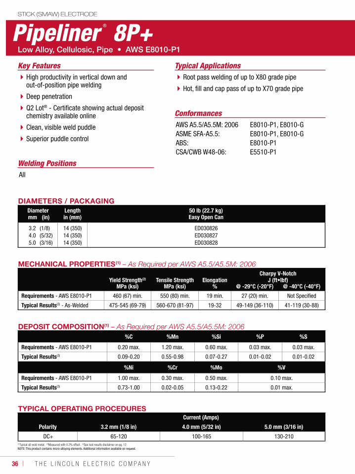
36 ı T H E L I N C O L N E L E C T R I C C O M P A N Y
STICK (SMAW) ELECTRODE
Pipeliner ® 8P+
Welding Positions
Typical Applications
All
Root pass welding of up to X80 grade pipe
Hot, fill and cap pass of up to X70 grade pipe
High productivity in vertical down and out-of-position pipe welding
Deep penetration
Q2 Lot® - Certificate showing actual deposit chemistry available online
Clean, visible weld puddle
Superior puddle control
Conformances
Key Features
AWS A5.5/A5.5M: 2006ASME SFA-A5.5:ABS:CSA/CWB W48-06:
E8010-P1, E8010-GE8010-P1, E8010-GE8010-P1E5510-P1
DIAMETERS / PACKAGINGDiameter Length 50 lb (22.7 kg)
Easy Open Canmm (in) in (mm)
3.24.05.0
(1/8)(5/32)(3/16)
14 (350)14 (350)14 (350)
ED030826ED030827ED030828
TYPICAL OPERATING PROCEDURESCurrent (Amps)
Polarity 3.2 mm (1/8 in) 4.0 mm (5/32 in) 5.0 mm (3/16 in)
DC+ 65-120 100-165 130-210
MECHANICAL PROPERTIES(1)
Yield Strength(2) Tensile Strength ElongationCharpy V-Notch
J (ft•lbf)MPa (ksi) MPa (ksi) % @ -29°C (-20°F) @ -40°C (-40°F)
Requirements - AWS E8010-P1 460 (67) min. 550 (80) min. 19 min. 27 (20) min. Not Specified
Typical Results(3) - As-Welded 475-545 (69-79) 560-670 (81-97) 19-32 49-149 (36-110) 41-119 (30-88)
DEPOSIT COMPOSITION(1)
%C %Mn %Si %P %S
Requirements - AWS E8010-P1 0.20 max. 1.20 max. 0.60 max. 0.03 max. 0.03 max.
Typical Results(3) 0.09-0.20 0.55-0.98 0.07-0.27 0.01-0.02 0.01-0.02
%Ni %Cr %Mo %V
Requirements - AWS E8010-P1 1.00 max. 0.30 max. 0.50 max. 0.10 max.
Typical Results(3) 0.73-1.00 0.02-0.05 0.13-0.22 0.01 max.
(1)Typical all weld metal. (2)Measured with 0.2% offset. (3)See test results disclaimer on pg. 12. NOTE: This product contains micro-alloying elements. Additional information available on request.
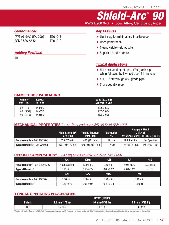
W E L D I N G C O N S U M A B L E S C A T A L O G ı 37
STICK (SMAW) ELECTRODE
Shield-Arc ® 90
Welding Positions
Typical Applications
All
Hot pass welding of up to X80 grade pipe, when followed by low hydrogen fill and cap
API 5L X70 through X80 grade pipe
Cross country pipe
Light slag for minimal arc interference
Deep penetration
Clean, visible weld puddle
Superior puddle control
Conformances
AWS E9010-G • Low Alloy, Cellulosic, Pipe
Key FeaturesAWS A5.5/A5.5M: 2006ASME SFA-A5.5:
E9010-GE9010-G
DIAMETERS / PACKAGINGDiameter Length 50 lb (22.7 kg)
Easy Open Canmm (in) in (mm)
3.24.05.0
(1/8)(5/32)(3/16)
14 (350)14 (350)14 (350)
EDS01693EDS01694EDS01695
TYPICAL OPERATING PROCEDURESCurrent (Amps)
Polarity 3.2 mm (1/8 in) 4.0 mm (5/32 in) 4.8 mm (3/16 in)
DC+ 75-130 80-185 140-225
MECHANICAL PROPERTIES(1) – As Required per AWS A5.5/A5.5M: 2006
Yield Strength(2) Tensile Strength ElongationCharpy V-Notch
J (ft•lbf)MPa (ksi) MPa (ksi) % @ -29°C (-20°F) @ -46°C (-50°F)
Requirements - AWS E9010-G 530 (77) min. 620 (90) min. 17 min. Not Specified Not Specified
Typical Results(3) - As-Welded 530-605 (77-88) 620-690 (90-100) 17-29 45-94 (33-69) 28-62 (21-46)
DEPOSIT COMPOSITION(1) – As Required per AWS A5.5/A5.5M: 2006%C %Mn %Si %P %S
Requirements(4) - AWS E9010-G Not Specified 1.00 min. 0.80 min. 0.03 max. 0.03 max.
Typical Results(3) 0.13-0.18 0.55-0.79 0.08-0.22 0.01-0.02 0.01
%Ni %Cr %Mo %V
Requirements - AWS E9010-G 0.50 min. 0.30 min. 0.20 min. 0.10 min.
Typical Results(3) 0.66-0.77 0.01-0.06 0.43-0.70 0.01
(1)Typical all weld metal. (2)Measured with 0.2% offset. (3)See test results disclaimer on pg. 12. (4)In order to meet the alloy requirements of the “G” designation, the undiluted weld metal shall have the minimum of at least one of the elements listed.
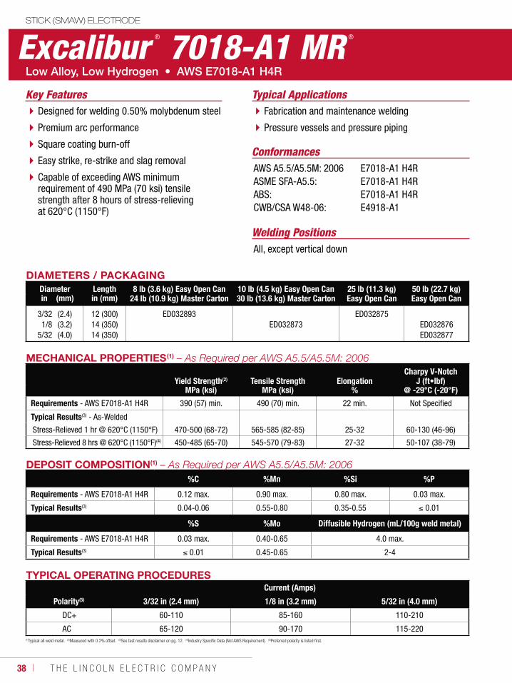
38 ı T H E L I N C O L N E L E C T R I C C O M P A N Y
STICK (SMAW) ELECTRODE
Excalibur ® 7018-A1 MR ®
Welding Positions
Typical Applications
All, except vertical down
Fabrication and maintenance welding
Pressure vessels and pressure piping
Designed for welding 0.50% molybdenum steel
Premium arc performance
Square coating burn-off
Easy strike, re-strike and slag removal
Capable of exceeding AWS minimum requirement of 490 MPa (70 ksi) tensile strength after 8 hours of stress-relieving at 620°C (1150°F)
Conformances
Key Features
AWS A5.5/A5.5M: 2006ASME SFA-A5.5:ABS:CWB/CSA W48-06:
E7018-A1 H4RE7018-A1 H4RE7018-A1 H4RE4918-A1
DIAMETERS / PACKAGINGDiameter Length 8 lb (3.6 kg) Easy Open Can
24 lb (10.9 kg) Master Carton10 lb (4.5 kg) Easy Open Can30 lb (13.6 kg) Master Carton
25 lb (11.3 kg) Easy Open Can
50 lb (22.7 kg)Easy Open Canin (mm) in (mm)
3/321/8
5/32
(2.4)(3.2)(4.0)
12 (300)14 (350)14 (350)
ED032893ED032873
ED032875ED032876ED032877
DEPOSIT COMPOSITION(1)
%C %Mn %Si %P
Requirements - AWS E7018-A1 H4R 0.12 max. 0.90 max. 0.80 max. 0.03 max.
Typical Results(3) 0.04-0.06 0.55-0.80 0.35-0.55 0.01
%S %Mo Diffusible Hydrogen (mL/100g weld metal)
Requirements - AWS E7018-A1 H4R 0.03 max. 0.40-0.65 4.0 max.
Typical Results(3) 0.01 0.45-0.65 2-4
TYPICAL OPERATING PROCEDURESCurrent (Amps)
Polarity(5) 3/32 in (2.4 mm) 1/8 in (3.2 mm) 5/32 in (4.0 mm)
DC+ 60-110 85-160 110-210
AC 65-120 90-170 115-220(1)Typical all weld metal. (2)Measured with 0.2% offset. (3)See test results disclaimer on pg. 12. (4)Industry Specific Data (Not AWS Requirement). (5)Preferred polarity is listed first.
MECHANICAL PROPERTIES(1)
Yield Strength(2) Tensile Strength ElongationCharpy V-Notch
J (ft•lbf)MPa (ksi) MPa (ksi) % @ -29°C (-20°F)
Requirements - AWS E7018-A1 H4R 390 (57) min. 490 (70) min. 22 min. Not Specified
Typical Results(3) - As-Welded
Stress-Relieved 1 hr @ 620°C (1150°F) 470-500 (68-72) 565-585 (82-85) 25-32 60-130 (46-96)
Stress-Relieved 8 hrs @ 620°C (1150°F)(4) 450-485 (65-70) 545-570 (79-83) 27-32 50-107 (38-79)
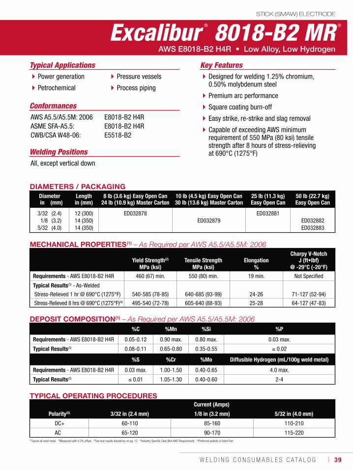
W E L D I N G C O N S U M A B L E S C A T A L O G ı 39
STICK (SMAW) ELECTRODE
Excalibur ® 8018-B2 MR ®
Welding Positions
Typical Applications
All, except vertical down
Power generation
Petrochemical
Pressure vessels
Process piping
Designed for welding 1.25% chromium, 0.50% molybdenum steel
Premium arc performance
Square coating burn-off
Easy strike, re-strike and slag removal
Capable of exceeding AWS minimum requirement of 550 MPa (80 ksi) tensile strength after 8 hours of stress-relieving at 690°C (1275°F)
Conformances
Key Features
AWS A5.5/A5.5M: 2006ASME SFA-A5.5:CWB/CSA W48-06:
E8018-B2 H4RE8018-B2 H4RE5518-B2
DIAMETERS / PACKAGINGDiameter Length 8 lb (3.6 kg) Easy Open Can
24 lb (10.9 kg) Master Carton10 lb (4.5 kg) Easy Open Can30 lb (13.6 kg) Master Carton
25 lb (11.3 kg)Easy Open Can
50 lb (22.7 kg)Easy Open Canin (mm) in (mm)
3/321/8
5/32
(2.4)(3.2)(4.0)
12 (300)14 (350)14 (350)
ED032878ED032879
ED032881ED032882ED032883
TYPICAL OPERATING PROCEDURESCurrent (Amps)
Polarity(5) 3/32 in (2.4 mm) 1/8 in (3.2 mm) 5/32 in (4.0 mm)
DC+ 60-110 85-160 110-210
AC 65-120 90-170 115-220(1)Typical all weld metal. (2)Measured with 0.2% offset. (3)See test results disclaimer on pg. 12. (4)Industry Specific Data (Not AWS Requirement). (5)Preferred polarity is listed first.
MECHANICAL PROPERTIES(1)
Yield Strength(2) Tensile Strength ElongationCharpy V-Notch
J (ft•lbf)MPa (ksi) MPa (ksi) % @ -29°C (-20°F)
Requirements - AWS E8018-B2 H4R 460 (67) min. 550 (80) min. 19 min. Not Specified
Typical Results(3) - As-Welded
Stress-Relieved 1 hr @ 690°C (1275°F) 540-585 (78-85) 640-685 (93-99) 24-26 71-127 (52-94)
Stress-Relieved 8 hrs @ 690°C (1275°F)(4) 495-540 (72-78) 605-640 (88-93) 25-28 64-127 (47-83)
DEPOSIT COMPOSITION(1)
%C %Mn %Si %P
Requirements - AWS E8018-B2 H4R 0.05-0.12 0.90 max. 0.80 max. 0.03 max.
Typical Results(3) 0.08-0.11 0.65-0.80 0.35-0.55 0.02
%S %Cr %Mo Diffusible Hydrogen (mL/100g weld metal)
Requirements - AWS E8018-B2 H4R 0.03 max. 1.00-1.50 0.40-0.65 4.0 max.
Typical Results(3) 0.01 1.05-1.30 0.40-0.60 2-4
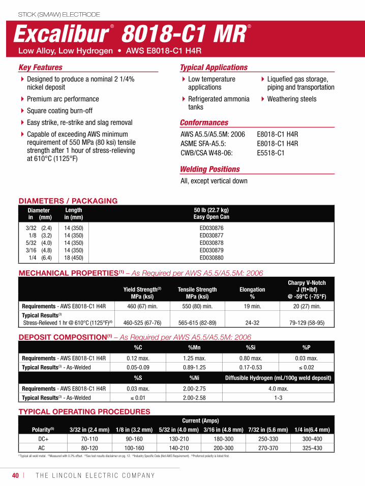
40 ı T H E L I N C O L N E L E C T R I C C O M P A N Y
STICK (SMAW) ELECTRODE
Excalibur ® 8018-C1 MR ®
Welding Positions
Typical Applications
All, except vertical down
Low temperature applications
Refrigerated ammonia tanks
Liquefied gas storage, piping and transportation
Weathering steels
Designed to produce a nominal 2 1/4% nickel deposit
Premium arc performance
Square coating burn-off
Easy strike, re-strike and slag removal
Capable of exceeding AWS minimum requirement of 550 MPa (80 ksi) tensile strength after 1 hour of stress-relieving at 610°C (1125°F)
Conformances
Key Features
AWS A5.5/A5.5M: 2006ASME SFA-A5.5:CWB/CSA W48-06:
E8018-C1 H4RE8018-C1 H4RE5518-C1
DIAMETERS / PACKAGINGDiameter Length 50 lb (22.7 kg)
Easy Open Canin (mm) in (mm)
3/321/8
5/323/161/4
(2.4)(3.2)(4.0)(4.8)(6.4)
14 (350)14 (350)14 (350)14 (350)18 (450)
ED030876ED030877ED030878ED030879ED030880
DEPOSIT COMPOSITION(1)
%C %Mn %Si %P
Requirements - AWS E8018-C1 H4R 0.12 max. 1.25 max. 0.80 max. 0.03 max.
Typical Results(3) - As-Welded 0.05-0.09 0.89-1.25 0.17-0.53 0.02
%S %Ni Diffusible Hydrogen (mL/100g weld deposit)
Requirements - AWS E8018-C1 H4R 0.03 max. 2.00-2.75 4.0 max.
Typical Results(3) - As-Welded 0.01 2.00-2.58 1-3
TYPICAL OPERATING PROCEDURESCurrent (Amps)
Polarity(5) 3/32 in (2.4 mm) 1/8 in (3.2 mm) 5/32 in (4.0 mm) 3/16 in (4.8 mm) 7/32 in (5.6 mm) 1/4 in(6.4 mm)
DC+ 70-110 90-160 130-210 180-300 250-330 300-400
AC 80-120 100-160 140-210 200-300 270-370 325-430
MECHANICAL PROPERTIES(1)
Yield Strength(2) Tensile Strength ElongationCharpy V-Notch
J (ft•lbf)MPa (ksi) MPa (ksi) % @ -59°C (-75°F)
Requirements - AWS E8018-C1 H4R 460 (67) min. 550 (80) min. 19 min. 20 (27) min.
Typical Results(3)
Stress-Relieved 1 hr @ 610°C (1125°F)(4) 460-525 (67-76) 565-615 (82-89) 24-32 79-129 (58-95)
(1)Typical all weld metal. (2)Measured with 0.2% offset. (3)See test results disclaimer on pg. 12. (4)Industry Specific Data (Not AWS Requirement). (5)Preferred polarity is listed first.
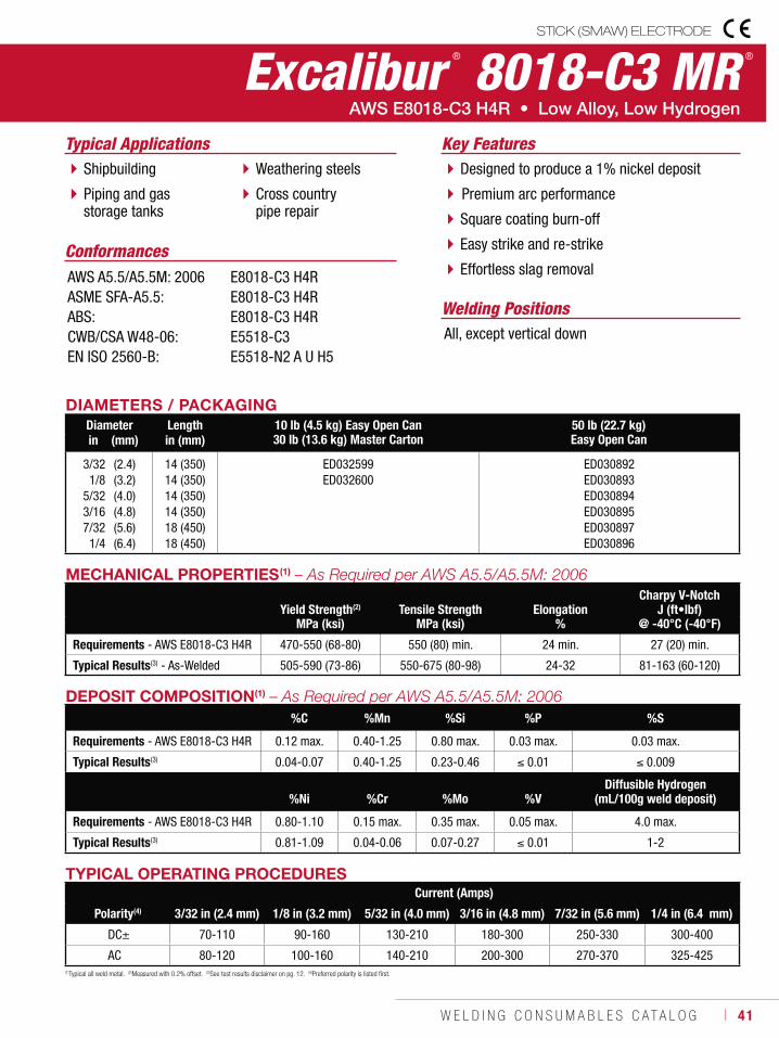
W E L D I N G C O N S U M A B L E S C A T A L O G ı 41
STICK (SMAW) ELECTRODE
Excalibur ® 8018-C3 MR ®
Welding Positions
Typical Applications
All, except vertical down
Shipbuilding
Piping and gas storage tanks
Weathering steels
Cross country pipe repair
Designed to produce a 1% nickel deposit
Premium arc performance
Square coating burn-off
Easy strike and re-strike
Effortless slag removalConformances
Key Features
AWS A5.5/A5.5M: 2006ASME SFA-A5.5:ABS:CWB/CSA W48-06:EN ISO 2560-B:
E8018-C3 H4RE8018-C3 H4RE8018-C3 H4RE5518-C3E5518-N2 A U H5
DIAMETERS / PACKAGINGDiameter Length 10 lb (4.5 kg) Easy Open Can
30 lb (13.6 kg) Master Carton50 lb (22.7 kg)Easy Open Canin (mm) in (mm)
3/321/8
5/323/167/321/4
(2.4)(3.2)(4.0)(4.8)(5.6)(6.4)
14 (350)14 (350)14 (350)14 (350)18 (450)18 (450)
ED032599ED032600
ED030892ED030893ED030894ED030895ED030897ED030896
TYPICAL OPERATING PROCEDURESCurrent (Amps)
Polarity(4) 3/32 in (2.4 mm) 1/8 in (3.2 mm) 5/32 in (4.0 mm) 3/16 in (4.8 mm) 7/32 in (5.6 mm) 1/4 in (6.4 mm)
DC± 70-110 90-160 130-210 180-300 250-330 300-400
AC 80-120 100-160 140-210 200-300 270-370 325-425
MECHANICAL PROPERTIES(1)
Yield Strength(2) Tensile Strength ElongationCharpy V-Notch
J (ft•lbf)MPa (ksi) MPa (ksi) % @ -40°C (-40°F)
Requirements - AWS E8018-C3 H4R 470-550 (68-80) 550 (80) min. 24 min. 27 (20) min.
Typical Results(3) - As-Welded 505-590 (73-86) 550-675 (80-98) 24-32 81-163 (60-120)
(1)Typical all weld metal. (2)Measured with 0.2% offset. (3)See test results disclaimer on pg. 12. (4)Preferred polarity is listed first.
DEPOSIT COMPOSITION(1)
%C %Mn %Si %P %S
Requirements - AWS E8018-C3 H4R 0.12 max. 0.40-1.25 0.80 max. 0.03 max. 0.03 max.
Typical Results(3) 0.04-0.07 0.40-1.25 0.23-0.46 0.01 0.009
%Ni %Cr %Mo %VDiffusible Hydrogen
(mL/100g weld deposit)
Requirements - AWS E8018-C3 H4R 0.80-1.10 0.15 max. 0.35 max. 0.05 max. 4.0 max.
Typical Results(3) 0.81-1.09 0.04-0.06 0.07-0.27 0.01 1-2
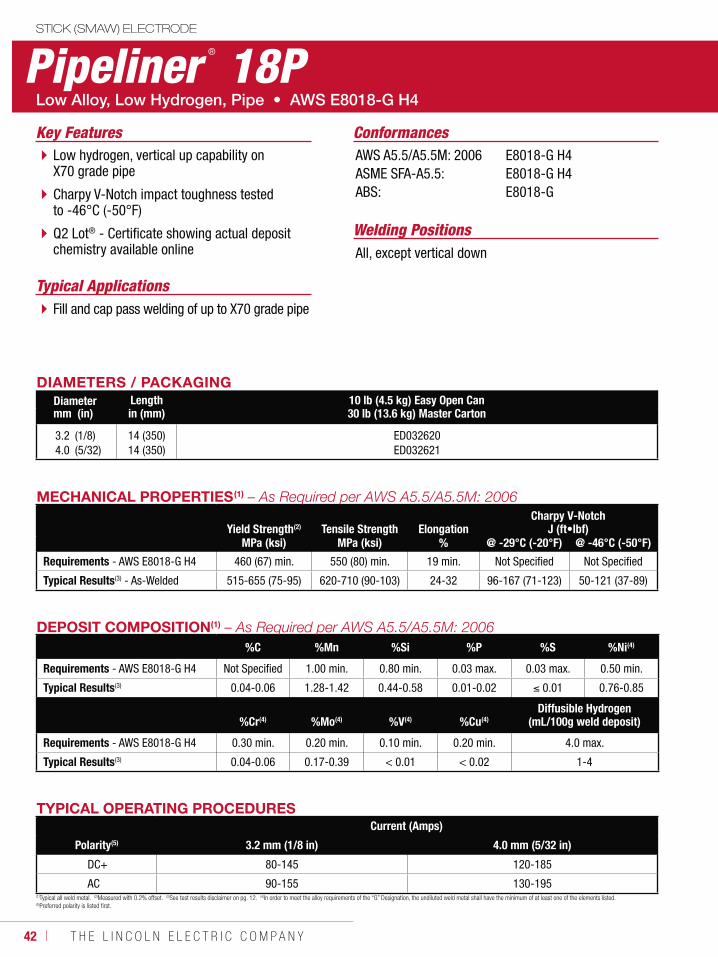
42 ı T H E L I N C O L N E L E C T R I C C O M P A N Y
STICK (SMAW) ELECTRODE
Pipeliner ® 18P
Welding Positions
Typical Applications
All, except vertical down
Fill and cap pass welding of up to X70 grade pipe
Low hydrogen, vertical up capability on X70 grade pipe
Charpy V-Notch impact toughness tested to -46°C (-50°F)
Q2 Lot® - Certificate showing actual deposit chemistry available online
ConformancesKey FeaturesAWS A5.5/A5.5M: 2006ASME SFA-A5.5:ABS:
E8018-G H4E8018-G H4E8018-G
DIAMETERS / PACKAGINGDiameter Length 10 lb (4.5 kg) Easy Open Can
30 lb (13.6 kg) Master Cartonmm (in) in (mm)
3.24.0
(1/8)(5/32)
14 (350)14 (350)
ED032620ED032621
TYPICAL OPERATING PROCEDURESCurrent (Amps)
Polarity(5) 3.2 mm (1/8 in) 4.0 mm (5/32 in)
DC+ 80-145 120-185
AC 90-155 130-195
MECHANICAL PROPERTIES(1)
Yield Strength(2) Tensile Strength ElongationCharpy V-Notch
J (ft•lbf)MPa (ksi) MPa (ksi) % @ -29°C (-20°F) @ -46°C (-50°F)
Requirements - AWS E8018-G H4 460 (67) min. 550 (80) min. 19 min. Not Specified Not Specified
Typical Results(3) - As-Welded 515-655 (75-95) 620-710 (90-103) 24-32 96-167 (71-123) 50-121 (37-89)
(1)Typical all weld metal. (2)Measured with 0.2% offset. (3)See test results disclaimer on pg. 12. (4)In order to meet the alloy requirements of the “G” Designation, the undiluted weld metal shall have the minimum of at least one of the elements listed. (5)Preferred polarity is listed first.
DEPOSIT COMPOSITION(1)
%C %Mn %Si %P %S %Ni(4)
Requirements - AWS E8018-G H4 Not Specified 1.00 min. 0.80 min. 0.03 max. 0.03 max. 0.50 min.
Typical Results(3) 0.04-0.06 1.28-1.42 0.44-0.58 0.01-0.02 0.01 0.76-0.85
%Cr(4) %Mo(4) %V(4) %Cu(4)Diffusible Hydrogen
(mL/100g weld deposit)
Requirements - AWS E8018-G H4 0.30 min. 0.20 min. 0.10 min. 0.20 min. 4.0 max.
Typical Results(3) 0.04-0.06 0.17-0.39 < 0.01 < 0.02 1-4
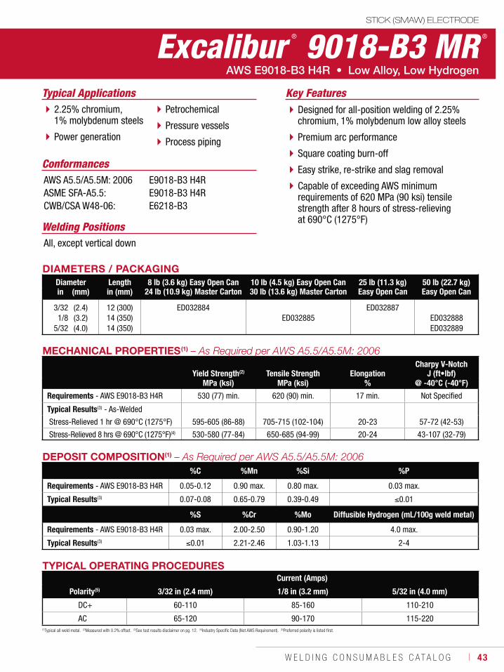
W E L D I N G C O N S U M A B L E S C A T A L O G ı 43
STICK (SMAW) ELECTRODE
Excalibur ® 9018-B3 MR ®
Welding Positions
Typical Applications
All, except vertical down
2.25% chromium, 1% molybdenum steels
Power generation
Petrochemical
Pressure vessels
Process piping
Designed for all-position welding of 2.25% chromium, 1% molybdenum low alloy steels
Premium arc performance
Square coating burn-off
Easy strike, re-strike and slag removal
Capable of exceeding AWS minimum requirements of 620 MPa (90 ksi) tensile strength after 8 hours of stress-relieving at 690°C (1275°F)
Conformances
Key Features
AWS A5.5/A5.5M: 2006ASME SFA-A5.5:CWB/CSA W48-06:
E9018-B3 H4RE9018-B3 H4RE6218-B3
DIAMETERS / PACKAGINGDiameter Length 8 lb (3.6 kg) Easy Open Can
24 lb (10.9 kg) Master Carton10 lb (4.5 kg) Easy Open Can30 lb (13.6 kg) Master Carton
25 lb (11.3 kg) Easy Open Can
50 lb (22.7 kg)Easy Open Canin (mm) in (mm)
3/321/8
5/32
(2.4)(3.2)(4.0)
12 (300)14 (350)14 (350)
ED032884ED032885
ED032887ED032888ED032889
TYPICAL OPERATING PROCEDURESCurrent (Amps)
Polarity(5) 3/32 in (2.4 mm) 1/8 in (3.2 mm) 5/32 in (4.0 mm)
DC+ 60-110 85-160 110-210
AC 65-120 90-170 115-220(1)Typical all weld metal. (2)Measured with 0.2% offset. (3)See test results disclaimer on pg. 12. (4)Industry Specific Data (Not AWS Requirement). (5)Preferred polarity is listed first.
MECHANICAL PROPERTIES(1)
Yield Strength(2) Tensile Strength ElongationCharpy V-Notch
J (ft•lbf)MPa (ksi) MPa (ksi) % @ -40°C (-40°F)
Requirements - AWS E9018-B3 H4R 530 (77) min. 620 (90) min. 17 min. Not Specified
Typical Results(3) - As-Welded
Stress-Relieved 1 hr @ 690°C (1275°F) 595-605 (86-88) 705-715 (102-104) 20-23 57-72 (42-53)
Stress-Relieved 8 hrs @ 690°C (1275°F)(4) 530-580 (77-84) 650-685 (94-99) 20-24 43-107 (32-79)
DEPOSIT COMPOSITION(1)
%C %Mn %Si %P
Requirements - AWS E9018-B3 H4R 0.05-0.12 0.90 max. 0.80 max. 0.03 max.
Typical Results(3) 0.07-0.08 0.65-0.79 0.39-0.49 0.01
%S %Cr %Mo Diffusible Hydrogen (mL/100g weld metal)
Requirements - AWS E9018-B3 H4R 0.03 max. 2.00-2.50 0.90-1.20 4.0 max.
Typical Results(3) 0.01 2.21-2.46 1.03-1.13 2-4
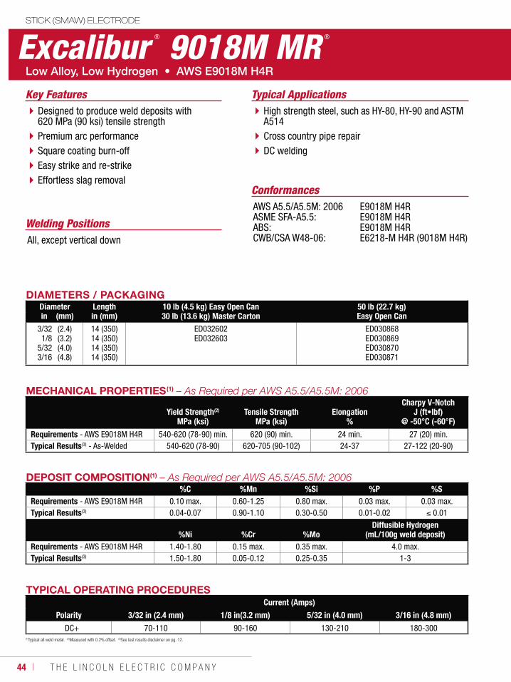
44 ı T H E L I N C O L N E L E C T R I C C O M P A N Y
DIAMETERS / PACKAGINGDiameter Length 10 lb (4.5 kg) Easy Open Can
30 lb (13.6 kg) Master Carton50 lb (22.7 kg)Easy Open Canin (mm) in (mm)
3/321/8
5/323/16
(2.4)(3.2)(4.0)(4.8)
14 (350)14 (350) 14 (350)14 (350)
ED032602ED032603
ED030868ED030869ED030870ED030871
TYPICAL OPERATING PROCEDURESCurrent (Amps)
Polarity 3/32 in (2.4 mm) 1/8 in(3.2 mm) 5/32 in (4.0 mm) 3/16 in (4.8 mm)
DC+ 70-110 90-160 130-210 180-300(1)Typical all weld metal. (2)Measured with 0.2% offset. (3)See test results disclaimer on pg. 12.
MECHANICAL PROPERTIES(1)
Yield Strength(2)
MPa (ksi)Tensile Strength
MPa (ksi)Elongation
%
Charpy V-NotchJ (ft•lbf)
@ -50°C (-60°F)
Requirements - AWS E9018M H4R 540-620 (78-90) min. 620 (90) min. 24 min. 27 (20) min.Typical Results(3) - As-Welded 540-620 (78-90) 620-705 (90-102) 24-37 27-122 (20-90)
DEPOSIT COMPOSITION(1)
%C %Mn %Si %P %SRequirements - AWS E9018M H4R 0.10 max. 0.60-1.25 0.80 max. 0.03 max. 0.03 max.Typical Results(3) 0.04-0.07 0.90-1.10 0.30-0.50 0.01-0.02 0.01
%Ni %Cr %MoDiffusible Hydrogen
(mL/100g weld deposit)Requirements - AWS E9018M H4R 1.40-1.80 0.15 max. 0.35 max. 4.0 max.Typical Results(3) 1.50-1.80 0.05-0.12 0.25-0.35 1-3
STICK (SMAW) ELECTRODE
Excalibur ® 9018M MR ®
Welding Positions
Typical Applications
All, except vertical down
High strength steel, such as HY-80, HY-90 and ASTM A514Cross country pipe repairDC welding
Designed to produce weld deposits with 620 MPa (90 ksi) tensile strength Premium arc performance Square coating burn-off Easy strike and re-strike Effortless slag removal
Conformances
Key Features
AWS A5.5/A5.5M: 2006ASME SFA-A5.5: ABS:CWB/CSA W48-06:
E9018M H4RE9018M H4RE9018M H4RE6218-M H4R (9018M H4R)
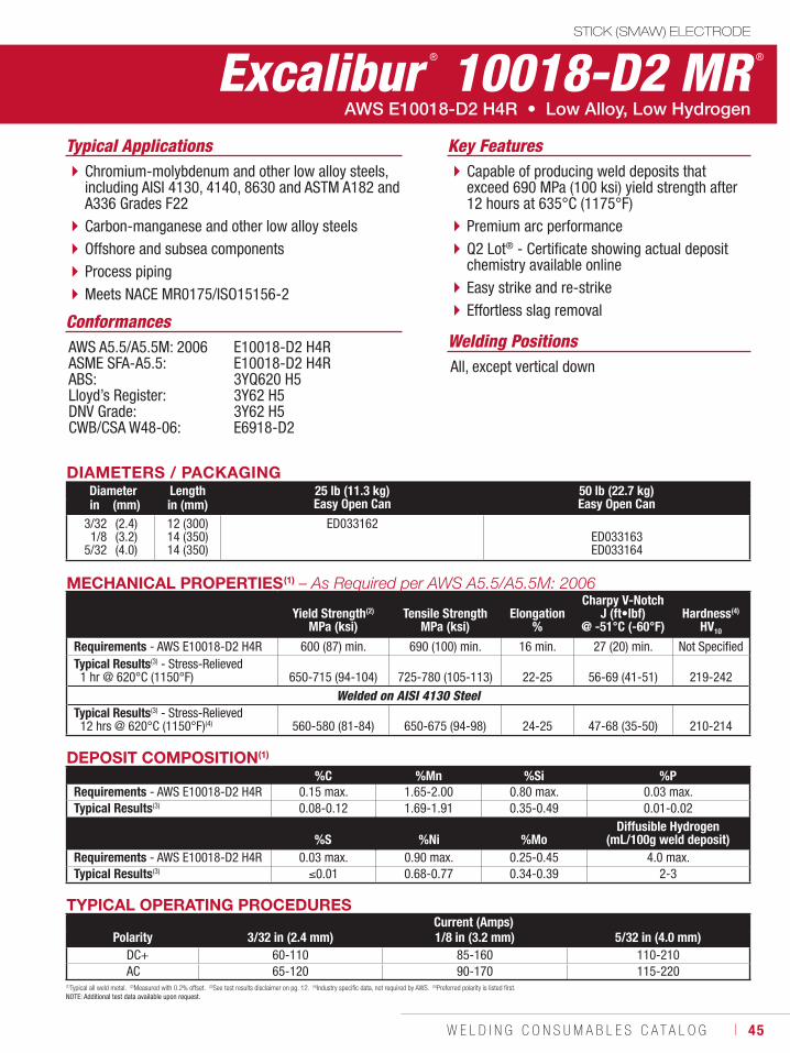
W E L D I N G C O N S U M A B L E S C A T A L O G ı 45
DIAMETERS / PACKAGINGDiameter Length 25 lb (11.3 kg)
Easy Open Can50 lb (22.7 kg)Easy Open Canin (mm) in (mm)
3/321/8
5/32
(2.4)(3.2)(4.0)
12 (300)14 (350)14 (350)
ED033162ED033163ED033164
(1)Typical all weld metal. (2)Measured with 0.2% offset. (3)See test results disclaimer on pg. 12. (4)Industry specific data, not required by AWS. (5)Preferred polarity is listed first. NOTE: Additional test data available upon request.
DEPOSIT COMPOSITION(1)
%C %Mn %Si %PRequirements - AWS E10018-D2 H4R 0.15 max. 1.65-2.00 0.80 max. 0.03 max.Typical Results(3) 0.08-0.12 1.69-1.91 0.35-0.49 0.01-0.02
%S %Ni %MoDiffusible Hydrogen
(mL/100g weld deposit)Requirements - AWS E10018-D2 H4R 0.03 max. 0.90 max. 0.25-0.45 4.0 max.Typical Results(3) 0.01 0.68-0.77 0.34-0.39 2-3
TYPICAL OPERATING PROCEDURESCurrent (Amps)
Polarity 3/32 in (2.4 mm) 1/8 in (3.2 mm) 5/32 in (4.0 mm)DC+ 60-110 85-160 110-210AC 65-120 90-170 115-220
MECHANICAL PROPERTIES(1) – As Required per AWS A5.5/A5.5M: 2006
Yield Strength(2)
MPa (ksi)Tensile Strength
MPa (ksi)Elongation
%
Charpy V-NotchJ (ft•lbf)
@ -51°C (-60°F)Hardness(4)
HV10
Requirements - AWS E10018-D2 H4R 600 (87) min. 690 (100) min. 16 min. 27 (20) min. Not SpecifiedTypical Results(3) - Stress-Relieved 1 hr @ 620°C (1150°F) 650-715 (94-104) 725-780 (105-113) 22-25 56-69 (41-51) 219-242
Welded on AISI 4130 SteelTypical Results(3) - Stress-Relieved 12 hrs @ 620°C (1150°F)(4) 560-580 (81-84) 650-675 (94-98) 24-25 47-68 (35-50) 210-214
STICK (SMAW) ELECTRODE
Excalibur ® 10018-D2 MR ®
Welding Positions
Typical Applications
All, except vertical down
Chromium-molybdenum and other low alloy steels, including AISI 4130, 4140, 8630 and ASTM A182 and A336 Grades F22Carbon-manganese and other low alloy steelsOffshore and subsea componentsProcess pipingMeets NACE MR0175/ISO15156-2
Capable of producing weld deposits that exceed 690 MPa (100 ksi) yield strength after 12 hours at 635°C (1175°F) Premium arc performanceQ2 Lot® - Certificate showing actual deposit chemistry available online Easy strike and re-strike Effortless slag removal
Conformances
AWS E10018-D2 H4R • Low Alloy, Low Hydrogen
Key Features
AWS A5.5/A5.5M: 2006ASME SFA-A5.5:ABS:Lloyd’s Register:DNV Grade:CWB/CSA W48-06:
E10018-D2 H4RE10018-D2 H4R3YQ620 H53Y62 H53Y62 H5E6918-D2
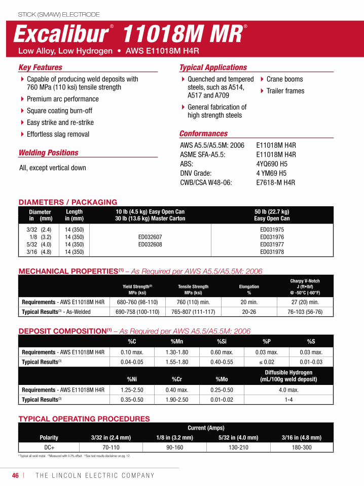
46 ı T H E L I N C O L N E L E C T R I C C O M P A N Y
STICK (SMAW) ELECTRODE
TYPICAL OPERATING PROCEDURESCurrent (Amps)
Polarity 3/32 in (2.4 mm) 1/8 in (3.2 mm) 5/32 in (4.0 mm) 3/16 in (4.8 mm)
DC+ 70-110 90-160 130-210 180-300(1)Typical all weld metal. (2)Measured with 0.2% offset. (3)See test results disclaimer on pg. 12.
MECHANICAL PROPERTIES(1)
Yield Strength(2) Tensile Strength ElongationCharpy V-Notch
J (ft•lbf)MPa (ksi) MPa (ksi) % @ -50°C (-60°F)
Requirements - AWS E11018M H4R 680-760 (98-110) 760 (110) min. 20 min. 27 (20) min.
Typical Results(3) - As-Welded 690-758 (100-110) 765-807 (111-117) 20-26 76-103 (56-76)
DEPOSIT COMPOSITION(1)
%C %Mn %Si %P %S
Requirements - AWS E11018M H4R 0.10 max. 1.30-1.80 0.60 max. 0.03 max. 0.03 max.
Typical Results(3) 0.04-0.05 1.55-1.80 0.40-0.55 0.02 0.01-0.03
%Ni %Cr %MoDiffusible Hydrogen
(mL/100g weld deposit)
Requirements - AWS E11018M H4R 1.25-2.50 0.40 max. 0.25-0.50 4.0 max.
Typical Results(3) 0.35-0.50 1.90-2.50 0.01-0.02 1-4
Excalibur ® 11018M MR ®
Welding Positions
Typical Applications
All, except vertical down
Quenched and tempered steels, such as A514, A517 and A709
General fabrication of high strength steels
Crane booms
Trailer frames
Capable of producing weld deposits with 760 MPa (110 ksi) tensile strength
Premium arc performance
Square coating burn-off
Easy strike and re-strike
Effortless slag removal Conformances
Key Features
AWS A5.5/A5.5M: 2006ASME SFA-A5.5:ABS:DNV Grade:CWB/CSA W48-06:
E11018M H4RE11018M H4R4YQ690 H54 YM69 H5E7618-M H4R
DIAMETERS / PACKAGINGDiameter Length 10 lb (4.5 kg) Easy Open Can
30 lb (13.6 kg) Master Carton50 lb (22.7 kg)Easy Open Canin (mm) in (mm)
3/321/8
5/323/16
(2.4)(3.2)(4.0)(4.8)
14 (350)14 (350)14 (350)14 (350)
ED032607ED032608
ED031975ED031976ED031977ED031978
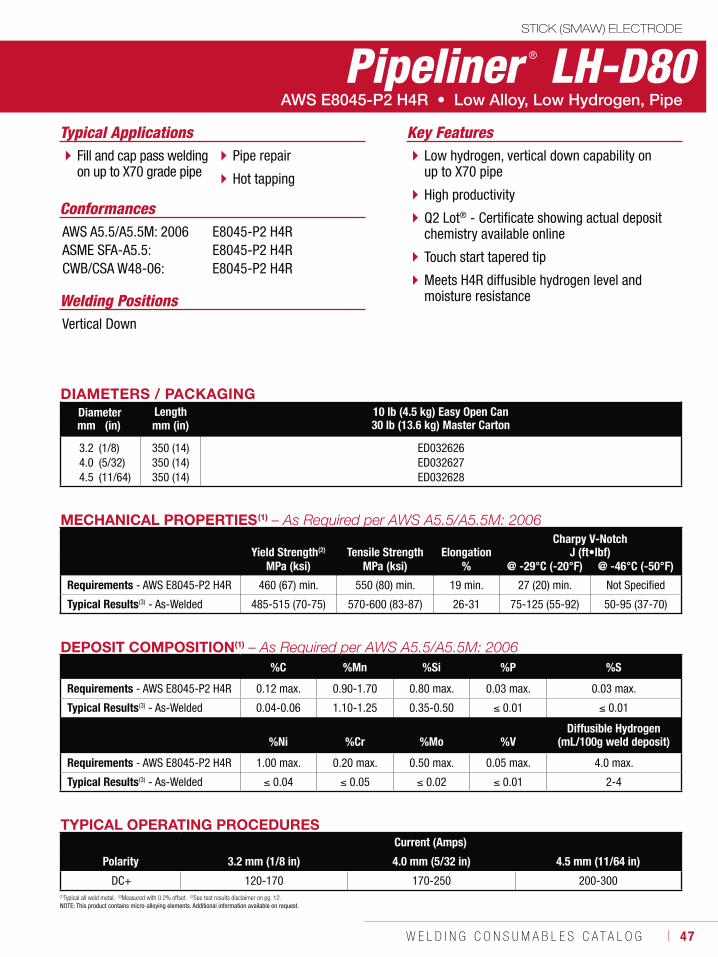
W E L D I N G C O N S U M A B L E S C A T A L O G ı 47
Pipeliner ® LH-D80STICK (SMAW) ELECTRODE
Welding Positions
Typical Applications
Vertical Down
Fill and cap pass welding on up to X70 grade pipe
Pipe repair
Hot tapping
Low hydrogen, vertical down capability on up to X70 pipe
High productivity
Q2 Lot® - Certificate showing actual deposit chemistry available online
Touch start tapered tip
Meets H4R diffusible hydrogen level and moisture resistance
Conformances
Key Features
AWS A5.5/A5.5M: 2006ASME SFA-A5.5:CWB/CSA W48-06:
E8045-P2 H4RE8045-P2 H4RE8045-P2 H4R
DIAMETERS / PACKAGINGDiameter Length 10 lb (4.5 kg) Easy Open Can
30 lb (13.6 kg) Master Cartonmm (in) mm (in)
3.24.04.5
(1/8)(5/32)(11/64)
350 (14)350 (14)350 (14)
ED032626ED032627ED032628
TYPICAL OPERATING PROCEDURESCurrent (Amps)
Polarity 3.2 mm (1/8 in) 4.0 mm (5/32 in) 4.5 mm (11/64 in)
DC+ 120-170 170-250 200-300
MECHANICAL PROPERTIES(1)
Yield Strength(2) Tensile Strength ElongationCharpy V-Notch
J (ft•lbf)MPa (ksi) MPa (ksi) % @ -29°C (-20°F) @ -46°C (-50°F)
Requirements - AWS E8045-P2 H4R 460 (67) min. 550 (80) min. 19 min. 27 (20) min. Not Specified
Typical Results(3) - As-Welded 485-515 (70-75) 570-600 (83-87) 26-31 75-125 (55-92) 50-95 (37-70)
(1)Typical all weld metal. (2)Measured with 0.2% offset. (3)See test results disclaimer on pg. 12. NOTE: This product contains micro-alloying elements. Additional information available on request.
DEPOSIT COMPOSITION(1)
%C %Mn %Si %P %S
Requirements - AWS E8045-P2 H4R 0.12 max. 0.90-1.70 0.80 max. 0.03 max. 0.03 max.
Typical Results(3) - As-Welded 0.04-0.06 1.10-1.25 0.35-0.50 0.01 0.01
%Ni %Cr %Mo %VDiffusible Hydrogen
(mL/100g weld deposit)
Requirements - AWS E8045-P2 H4R 1.00 max. 0.20 max. 0.50 max. 0.05 max. 4.0 max.
Typical Results(3) - As-Welded 0.04 0.05 0.02 0.01 2-4

48 ı T H E L I N C O L N E L E C T R I C C O M P A N Y
STICK (SMAW) ELECTRODE
Pipeliner ® LH-D90
Welding Positions
Typical Applications
Vertical Down
Fill and cap pass welding of up to X80 grade pipe
Pipe repair
Hot tapping
Low hydrogen, vertical down capability on up to X80 pipe
High productivity
Q2 Lot® - Certificate showing actual deposit chemistry available online
Touch start tapered tip
Meets H4R diffusible hydrogen level and moisture resistance
Conformances
Key Features
AWS A5.5/A5.5M: 2006ASME SFA-A5.5:CWB/CSA W48-06:
E9045-P2 H4RE9045-P2 H4RE9045-P2 H4R
DIAMETERS / PACKAGINGDiameter Length 10 lb (4.5 kg) Easy Open Can
30 lb (13.6 kg) Master Cartonmm (in) in (mm)
3.24.04.5
(1/8)(5/32)(11/64)
14 (350)14 (350)14 (350)
ED032629ED032630ED032631
MECHANICAL PROPERTIES(1)
Yield Strength(2) Tensile Strength ElongationCharpy V-Notch
J (ft•lbf)MPa (ksi) MPa (ksi) % @ -29°C (-20°F) @ -46°C (-50°F)
Requirements - AWS E9045-P2 H4R 530 (77) min. 620 (90) min. 17 min. 27 (20) min. Not Specified
Typical Results(3) - As-Welded 550-600 (80-87) 625-670 (91-97) 26-31 75-125 (55-92) 50-95 (37-70)
TYPICAL OPERATING PROCEDURESCurrent (Amps)
Polarity 3.2 mm (1/8 in) 4.0 mm (5/32 in) 4.5 mm (11/64 in)
DC+ 120-170 170-250 200-300 (1)Typical all weld metal. (2)Measured with 0.2% offset. (3)See test results disclaimer on pg. 12. (4)Range for 3.2 mm (1/8 in) size only. (5)Range for 4.0 mm (5/32 in) and 4.5 mm (11/64 in) sizes. NOTE: This product contains micro-alloying elements. Additional information available on request.
DEPOSIT COMPOSITION(1)
%C %Mn %Si %P %S
Requirements - AWS E9045-P2 H4R 0.12 max. 0.90-1.70 0.80 max. 0.03 max. 0.03 max.
Typical Results(3) - As-Welded 0.04-0.06 1.15-1.35 0.35-0.55 0.01 0.01
%Ni %Cr %Mo %VDiffusible Hydrogen
(mL/100g weld deposit)
Requirements - AWS E9045-P2 H4R 1.00 max. 0.20 max. 0.50 max. 0.05 max. 4.0 max.
Typical Results(3) - As-Welded 0.25-0.30(4) / 0.80-1.00(5) 0.05 0.15-0.25 0.01 2-4
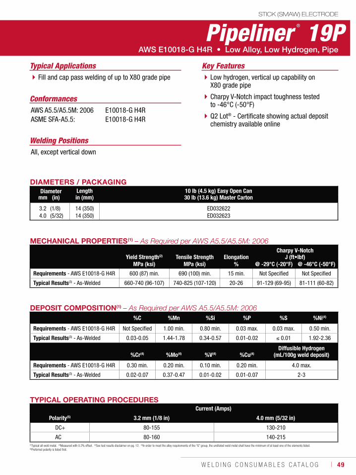
W E L D I N G C O N S U M A B L E S C A T A L O G ı 49
STICK (SMAW) ELECTRODE
Pipeliner ® 19P
Welding Positions
Typical Applications
All, except vertical down
Fill and cap pass welding of up to X80 grade pipe Low hydrogen, vertical up capability on X80 grade pipe
Charpy V-Notch impact toughness tested to -46°C (-50°F)
Q2 Lot® - Certificate showing actual deposit chemistry available online
Conformances
Key Features
AWS A5.5/A5.5M: 2006ASME SFA-A5.5:
E10018-G H4RE10018-G H4R
DIAMETERS / PACKAGINGDiameter Length 10 lb (4.5 kg) Easy Open Can
30 lb (13.6 kg) Master Cartonmm (in) in (mm)
3.24.0
(1/8)(5/32)
14 (350)14 (350)
ED032622ED032623
TYPICAL OPERATING PROCEDURESCurrent (Amps)
Polarity(5) 3.2 mm (1/8 in) 4.0 mm (5/32 in)
DC+ 80-155 130-210
AC 80-160 140-215
MECHANICAL PROPERTIES(1)
Yield Strength(2) Tensile Strength ElongationCharpy V-Notch
J (ft•lbf)MPa (ksi) MPa (ksi) % @ -29°C (-20°F) @ -46°C (-50°F)
Requirements - AWS E10018-G H4R 600 (87) min. 690 (100) min. 15 min. Not Specified Not Specified
Typical Results(3) - As-Welded 660-740 (96-107) 740-825 (107-120) 20-26 91-129 (69-95) 81-111 (60-82)
(1)Typical all weld metal. (2)Measured with 0.2% offset. (3)See test results disclaimer on pg. 12. (4)In order to meet the alloy requirements of the “G” group, the undiluted weld metal shall have the minimum of at least one of the elements listed. (5)Preferred polarity is listed first.
DEPOSIT COMPOSITION(1)
%C %Mn %Si %P %S %Ni(4)
Requirements - AWS E10018-G H4R Not Specified 1.00 min. 0.80 min. 0.03 max. 0.03 max. 0.50 min.
Typical Results(3) - As-Welded 0.03-0.05 1.44-1.78 0.34-0.57 0.01-0.02 0.01 1.92-2.36
%Cr(4) %Mo(4) %V(4) %Cu(4)Diffusible Hydrogen
(mL/100g weld deposit)
Requirements - AWS E10018-G H4R 0.30 min. 0.20 min. 0.10 min. 0.20 min. 4.0 max.
Typical Results(3) - As-Welded 0.02-0.07 0.37-0.47 0.01-0.02 0.01-0.07 2-3
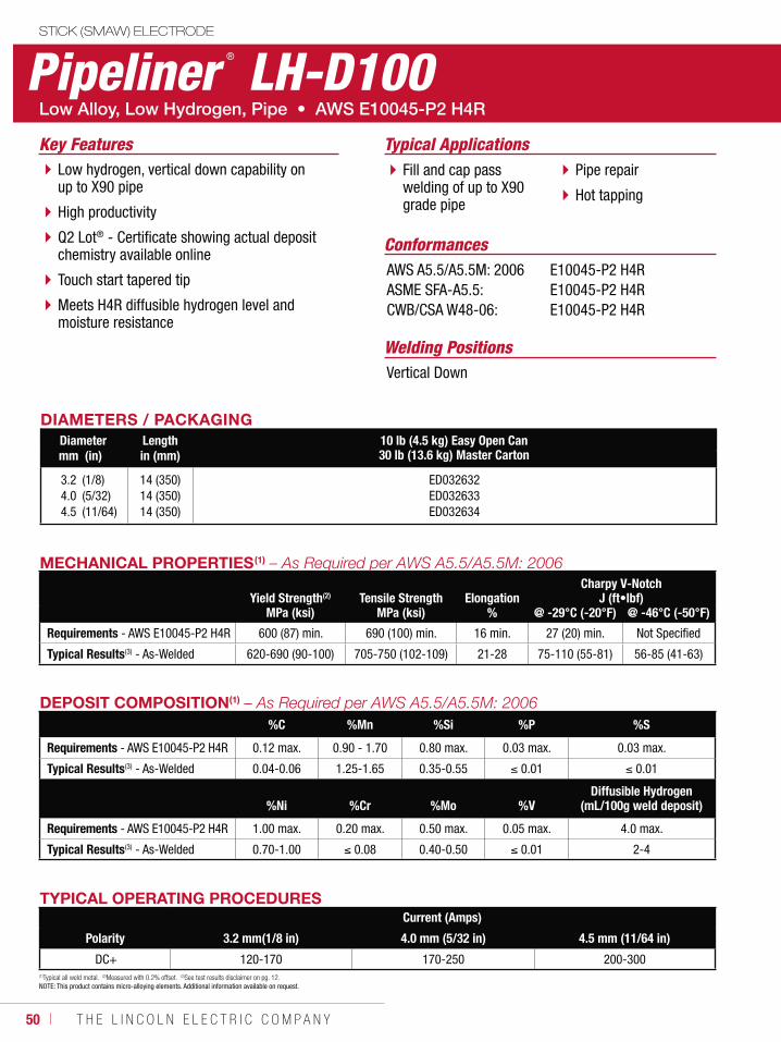
50 ı T H E L I N C O L N E L E C T R I C C O M P A N Y
STICK (SMAW) ELECTRODE
Pipeliner ® LH-D100
Welding Positions
Typical Applications
Vertical Down
Fill and cap pass welding of up to X90 grade pipe
Pipe repair
Hot tapping
Low hydrogen, vertical down capability on up to X90 pipe
High productivity
Q2 Lot® - Certificate showing actual deposit chemistry available online
Touch start tapered tip
Meets H4R diffusible hydrogen level and moisture resistance
Conformances
Key Features
AWS A5.5/A5.5M: 2006ASME SFA-A5.5:CWB/CSA W48-06:
E10045-P2 H4RE10045-P2 H4RE10045-P2 H4R
DIAMETERS / PACKAGINGDiameter Length 10 lb (4.5 kg) Easy Open Can
30 lb (13.6 kg) Master Cartonmm (in) in (mm)
3.24.04.5
(1/8)(5/32)(11/64)
14 (350)14 (350)14 (350)
ED032632ED032633ED032634
MECHANICAL PROPERTIES(1)
Yield Strength(2) Tensile Strength ElongationCharpy V-Notch
J (ft•lbf)MPa (ksi) MPa (ksi) % @ -29°C (-20°F) @ -46°C (-50°F)
Requirements - AWS E10045-P2 H4R 600 (87) min. 690 (100) min. 16 min. 27 (20) min. Not Specified
Typical Results(3) - As-Welded 620-690 (90-100) 705-750 (102-109) 21-28 75-110 (55-81) 56-85 (41-63)
TYPICAL OPERATING PROCEDURESCurrent (Amps)
Polarity 3.2 mm(1/8 in) 4.0 mm (5/32 in) 4.5 mm (11/64 in)
DC+ 120-170 170-250 200-300 (1)Typical all weld metal. (2)Measured with 0.2% offset. (3)See test results disclaimer on pg. 12. NOTE: This product contains micro-alloying elements. Additional information available on request.
DEPOSIT COMPOSITION(1)
%C %Mn %Si %P %S
Requirements - AWS E10045-P2 H4R 0.12 max. 0.90 - 1.70 0.80 max. 0.03 max. 0.03 max.
Typical Results(3) - As-Welded 0.04-0.06 1.25-1.65 0.35-0.55 0.01 0.01
%Ni %Cr %Mo %VDiffusible Hydrogen
(mL/100g weld deposit)
Requirements - AWS E10045-P2 H4R 1.00 max. 0.20 max. 0.50 max. 0.05 max. 4.0 max.
Typical Results(3) - As-Welded 0.70-1.00 0.08 0.40-0.50 0.01 2-4
W E L D I N G C O N S U M A B L E S ı 51
GMAW & GTAW CONSUMABLES
MIG WireMild Steel, BareSuperGlide® S3 ..............................................52SuperGlide® S6 ..............................................54
Mild Steel, Copper CoatedSuperArc® L-50® ............................................56SuperArc® L-56® ............................................58SuperArc® L-59® ............................................60
Low Alloy, Copper CoatedSuperArc® LA-75 ............................................62SuperArc® LA-90 ............................................64SuperArc® LA-100 ..........................................66
Mild and Low Alloy Steel PipePipeliner® 70S-G ............................................68Pipeliner® 80S-G ............................................69Pipeliner® 80Ni1 .............................................70
TIG Cut LengthMild Steel, Copper CoatedLincoln® ER70S-2...........................................71Lincoln® ER70S-6...........................................72
MIG & TIG
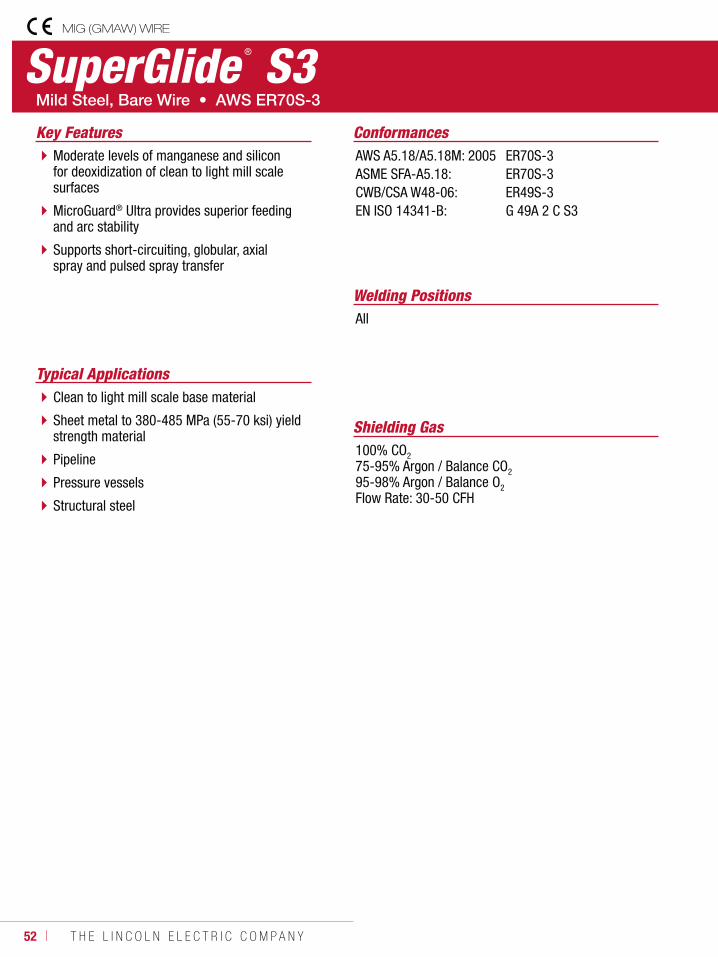
52 ı T H E L I N C O L N E L E C T R I C C O M P A N Y
SuperGlide ® S3MIG (GMAW) WIRE
Welding Positions
Typical Applications
All
Clean to light mill scale base material
Sheet metal to 380-485 MPa (55-70 ksi) yield strength material
Pipeline
Pressure vessels
Structural steel
Moderate levels of manganese and silicon for deoxidization of clean to light mill scale surfaces
MicroGuard® Ultra provides superior feeding and arc stability
Supports short-circuiting, globular, axial spray and pulsed spray transfer
Conformances
Shielding Gas100% CO2
75-95% Argon / Balance CO2
95-98% Argon / Balance O2
Flow Rate: 30-50 CFH
Key FeaturesAWS A5.18/A5.18M: 2005ASME SFA-A5.18:CWB/CSA W48-06:EN ISO 14341-B:
ER70S-3ER70S-3ER49S-3G 49A 2 C S3
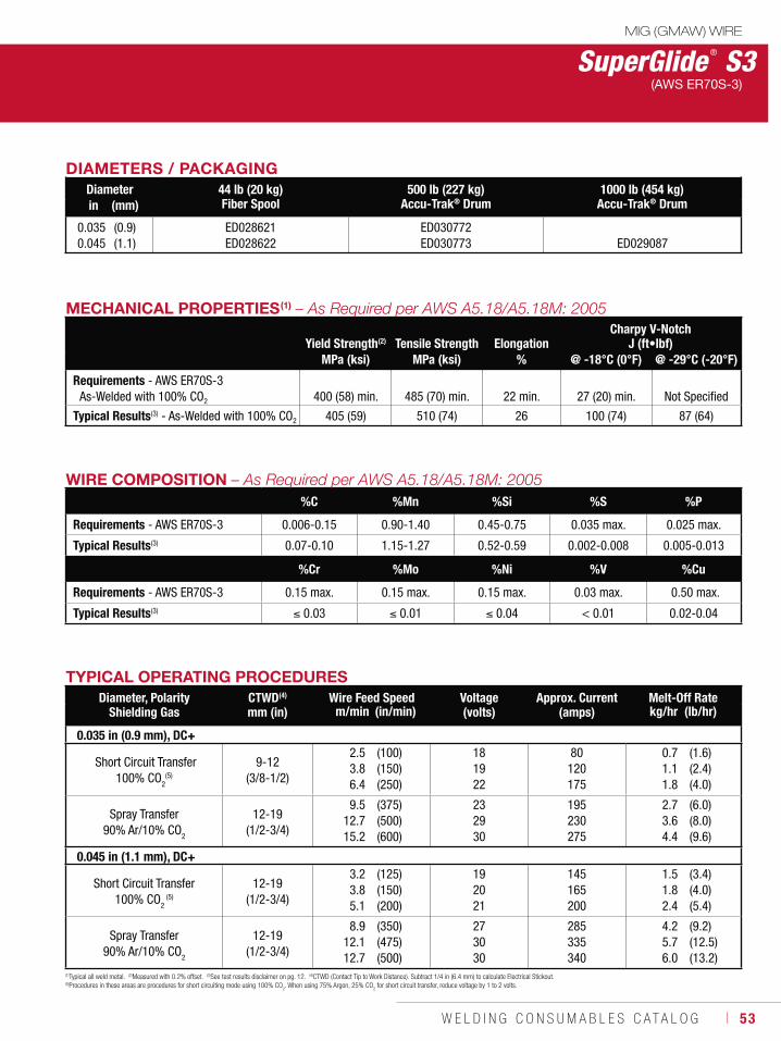
W E L D I N G C O N S U M A B L E S C A T A L O G ı 53
DIAMETERS / PACKAGINGDiameter 44 lb (20 kg)
Fiber Spool500 lb (227 kg)
Accu-Trak® Drum1000 lb (454 kg)
Accu-Trak® Drumin (mm)
0.0350.045
(0.9)(1.1)
ED028621 ED028622
ED030772ED030773 ED029087
MECHANICAL PROPERTIES(1)
Yield Strength(2) Tensile Strength ElongationCharpy V-Notch
J (ft•lbf)MPa (ksi) MPa (ksi) % @ -18°C (0°F) @ -29°C (-20°F)
Requirements - AWS ER70S-3As-Welded with 100% CO2 400 (58) min. 485 (70) min. 22 min. 27 (20) min. Not Specified
Typical Results(3) - As-Welded with 100% CO2 405 (59) 510 (74) 26 100 (74) 87 (64)
WIRE COMPOSITION%C %Mn %Si %S %P
Requirements - AWS ER70S-3 0.006-0.15 0.90-1.40 0.45-0.75 0.035 max. 0.025 max.
Typical Results(3) 0.07-0.10 1.15-1.27 0.52-0.59 0.002-0.008 0.005-0.013
%Cr %Mo %Ni %V %Cu
Requirements - AWS ER70S-3 0.15 max. 0.15 max. 0.15 max. 0.03 max. 0.50 max.
Typical Results(3) 0.03 0.01 0.04 < 0.01 0.02-0.04
SuperGlide ® S3MIG (GMAW) WIRE
(AWS ER70S-3)
(1)Typical all weld metal. (2)Measured with 0.2% offset. (3)See test results disclaimer on pg. 12. (4)CTWD (Contact Tip to Work Distance). Subtract 1/4 in (6.4 mm) to calculate Electrical Stickout. (5)Procedures in these areas are procedures for short circuiting mode using 100% CO
2. When using 75% Argon, 25% CO
2 for short circuit transfer, reduce voltage by 1 to 2 volts.
TYPICAL OPERATING PROCEDURESDiameter, Polarity
Shielding GasCTWD(4)
mm (in)Wire Feed Speed Voltage
(volts)Approx. Current
(amps)Melt-Off Rate
m/min (in/min) kg/hr (lb/hr)
0.035 in (0.9 mm), DC+
Short Circuit Transfer100% CO2
(5)
9-12 (3/8-1/2)
2.53.86.4
(100)(150)(250)
181922
80120175
0.71.11.8
(1.6)(2.4)(4.0)
Spray Transfer90% Ar/10% CO2
12-19 (1/2-3/4)
9.512.715.2
(375)(500)(600)
232930
195230275
2.73.64.4
(6.0)(8.0)(9.6)
0.045 in (1.1 mm), DC+
Short Circuit Transfer100% CO2
(5)
12-19 (1/2-3/4)
3.23.85.1
(125)(150)(200)
192021
145165200
1.51.82.4
(3.4)(4.0)(5.4)
Spray Transfer90% Ar/10% CO2
12-19 (1/2-3/4)
8.912.112.7
(350)(475)(500)
273030
285335340
4.25.76.0
(9.2)(12.5)(13.2)
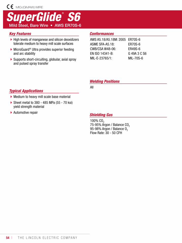
54 ı T H E L I N C O L N E L E C T R I C C O M P A N Y
SuperGlide ® S6
Welding Positions
Typical ApplicationsAll
Medium to heavy mill scale base material
Sheet metal to 380 - 485 MPa (55 - 70 ksi) yield strength material
Automotive repair
High levels of manganese and silicon deoxidizers tolerate medium to heavy mill scale surfaces
MicroGuard® Ultra provides superior feeding and arc stability
Supports short-circuiting, globular, axial spray and pulsed spray transfer
Conformances
Shielding Gas100% CO2
75-95% Argon / Balance CO2
95-98% Argon / Balance O2
Flow Rate: 30 - 50 CFH
Key FeaturesAWS A5.18/A5.18M: 2005ASME SFA-A5.18:CWB/CSA W48-06:EN ISO 14341-B:MIL-E-23765/1:
ER70S-6ER70S-6ER49S-6G 49A 3 C S6MIL-70S-6
MIG (GMAW) WIRE
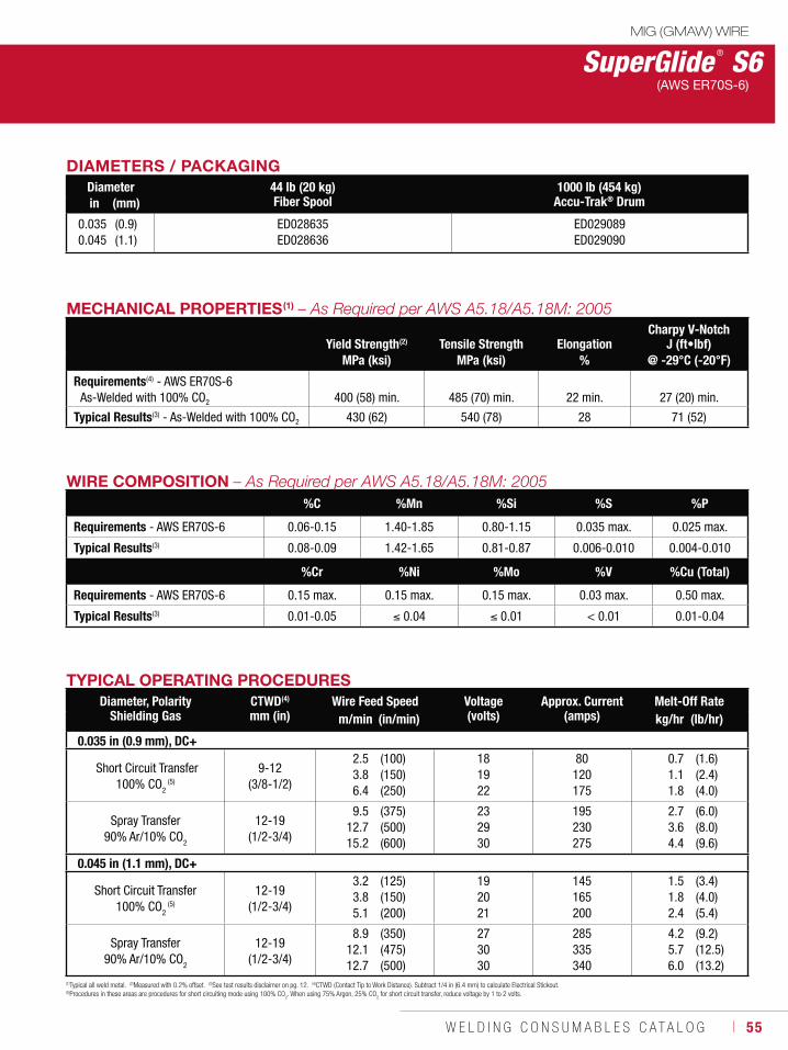
W E L D I N G C O N S U M A B L E S C A T A L O G ı 55
DIAMETERS / PACKAGINGDiameter 44 lb (20 kg)
Fiber Spool1000 lb (454 kg)
Accu-Trak® Drumin (mm)
0.0350.045
(0.9)(1.1)
ED028635 ED028636
ED029089 ED029090
MECHANICAL PROPERTIES(1)
Yield Strength(2) Tensile Strength ElongationCharpy V-Notch
J (ft•lbf)MPa (ksi) MPa (ksi) % @ -29°C (-20°F)
Requirements(4) - AWS ER70S-6As-Welded with 100% CO2
400 (58) min.
485 (70) min.
22 min.
27 (20) min.
Typical Results(3) - As-Welded with 100% CO2 430 (62) 540 (78) 28 71 (52)
SuperGlide ® S6(AWS ER70S-6)
(1)Typical all weld metal. (2)Measured with 0.2% offset. (3)See test results disclaimer on pg. 12. (4)CTWD (Contact Tip to Work Distance). Subtract 1/4 in (6.4 mm) to calculate Electrical Stickout. (5)Procedures in these areas are procedures for short circuiting mode using 100% CO
2. When using 75% Argon, 25% CO
2 for short circuit transfer, reduce voltage by 1 to 2 volts.
WIRE COMPOSITION%C %Mn %Si %S %P
Requirements - AWS ER70S-6 0.06-0.15 1.40-1.85 0.80-1.15 0.035 max. 0.025 max.
Typical Results(3) 0.08-0.09 1.42-1.65 0.81-0.87 0.006-0.010 0.004-0.010
%Cr %Ni %Mo %V %Cu (Total)
Requirements - AWS ER70S-6 0.15 max. 0.15 max. 0.15 max. 0.03 max. 0.50 max.
Typical Results(3) 0.01-0.05 0.04 0.01 < 0.01 0.01-0.04
TYPICAL OPERATING PROCEDURESDiameter, Polarity
Shielding GasCTWD(4)
mm (in)Wire Feed Speed Voltage
(volts)Approx. Current
(amps)Melt-Off Rate
m/min (in/min) kg/hr (lb/hr)
0.035 in (0.9 mm), DC+
Short Circuit Transfer100% CO2
(5)
9-12 (3/8-1/2)
2.53.86.4
(100)(150)(250)
181922
80120175
0.71.11.8
(1.6)(2.4)(4.0)
Spray Transfer90% Ar/10% CO2
12-19 (1/2-3/4)
9.512.715.2
(375)(500)(600)
232930
195230275
2.73.64.4
(6.0)(8.0)(9.6)
0.045 in (1.1 mm), DC+
Short Circuit Transfer100% CO2
(5)
12-19 (1/2-3/4)
3.23.85.1
(125)(150)(200)
192021
145165200
1.51.82.4
(3.4)(4.0)(5.4)
Spray Transfer90% Ar/10% CO2
12-19 (1/2-3/4)
8.912.112.7
(350)(475)(500)
273030
285335340
4.25.76.0
(9.2)(12.5)(13.2)
MIG (GMAW) WIRE
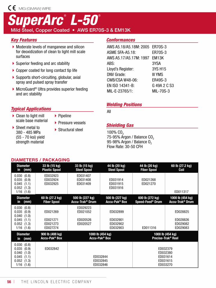
56 ı T H E L I N C O L N E L E C T R I C C O M P A N Y
SuperArc ® L-50 ®
Welding PositionsTypical Applications All
Clean to light mill scale base material
Sheet metal to 380 - 485 MPa (55 - 70 ksi) yield strength material
Pipeline
Pressure vessels
Structural steel
Moderate levels of manganese and silicon for deoxidization of clean to light mill scale surfaces
Superior feeding and arc stability
Copper coated for long contact tip life
Supports short-circuiting, globular, axial spray and pulsed spray transfer
MicroGuard® Ultra provides superior feeding and arc stability
Conformances
Shielding Gas100% CO2
75-95% Argon / Balance CO2
95-98% Argon / Balance O2
Flow Rate: 30-50 CFH
Key FeaturesAWS A5.18/A5.18M: 2005ASME SFA-A5.18:AWS A5.17/A5.17M: 1997ABS:Lloyd’s Register:DNV Grade:CWB/CSA W48-06:EN ISO 14341-B:MIL-E-23765/1:
ER70S-3ER70S-3EM13K3YSA3YS H15III YMSER49S-3G 49A 2 C S3MIL-70S-3
DIAMETERS / PACKAGINGDiameter 33 lb (15 kg)
Plastic Spool33 lb (15 kg)Steel Spool
44 lb (20 kg)Steel Spool
44 lb (20 kg)Fiber Spool
60 lb (27.2 kg)Coilin (mm)
0.0300.0350.0450.0521/16
(0.8)(0.9)(1.1)(1.3)(1.6)
ED032923ED032924ED032925
ED031407 ED031408 ED031409
ED031914ED031915ED031916
ED021268 ED021270
ED011317
Diameter 60 lb (27.2 kg)Fiber Spool
500 lb (227 kg)Accu-Trak® Drum
500 lb (227 kg)Accu-Pak® Box
600 lb (272 kg)Speed-Feed® Drum
1000 lb (454 kg)Accu-Trak® Drumin (mm)
0.0300.0350.0400.0450.0521/16
(0.8)(0.9)(1.0)(1.1)(1.3)(1.6)
ED021269
ED021271 ED021273 ED027274
ED029223 ED021052
ED020526 ED020527
ED032899
ED032901 ED032902 ED032903 ED011316
ED028825
ED028826 ED029082 ED029083
Diameter 900 lb (408 kg)Accu-Pak® Box
1000 lb (454 kg)Accu-Pak® Box
1000 lb (454 kg)Precise-Trak® Reelin (mm)
0.0300.0350.0400.0450.0521/16
(0.8)(0.9)(1.0)(1.1)(1.3)(1.6)
ED032842
EDO32844 EDO32845 EDO32846
ED032379ED032380ED031614ED031615ED033270
MIG (GMAW) WIRE
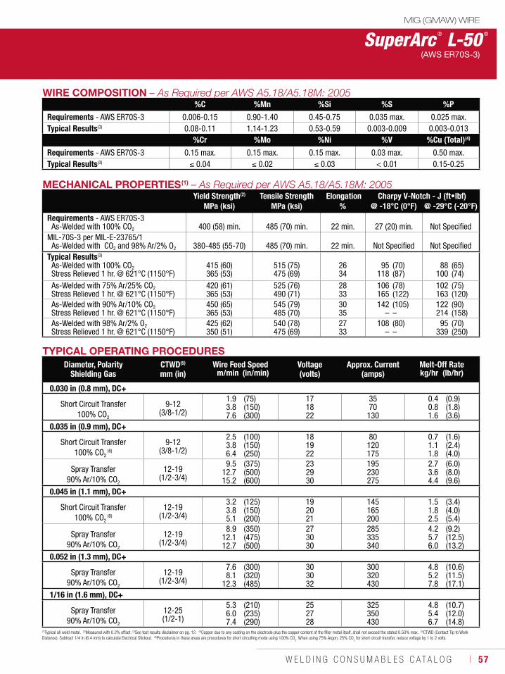
W E L D I N G C O N S U M A B L E S C A T A L O G ı 57
MECHANICAL PROPERTIES(1)
Yield Strength(2) Tensile Strength Elongation Charpy V-Notch - J (ft•lbf)MPa (ksi) MPa (ksi) % @ -18°C (0°F) @ -29°C (-20°F)
Requirements - AWS ER70S-3As-Welded with 100% CO2 400 (58) min. 485 (70) min. 22 min.
27 (20) min.
Not Specified
MIL-70S-3 per MIL-E-23765/1As-Welded with CO2 and 98% Ar/2% O2 380-485 (55-70) 485 (70) min. 22 min. Not Specified Not Specified
Typical Results(3)
As-Welded with 100% CO2Stress Relieved 1 hr. @ 621°C (1150°F)
415 (60)365 (53)
515 (75)475 (69)
2634
95118
(70)(87)
88100
(65)(74)
As-Welded with 75% Ar/25% CO2Stress Relieved 1 hr. @ 621°C (1150°F)
420 (61)365 (53)
525 (76)490 (71)
2833
106165
(78)(122)
102163
(75)(120)
As-Welded with 90% Ar/10% CO2Stress Relieved 1 hr. @ 621°C (1150°F)
450 (65)365 (53)
545 (79)485 (70)
3035
142–
(105)–
122214
(90)(158)
As-Welded with 98% Ar/2% O2
Stress Relieved 1 hr. @ 621°C (1150°F)425 (62)350 (51)
540 (78)475 (69)
2733
108–
(80)–
95339
(70)(250)
SuperArc ® L-50 ®
(AWS ER70S-3)
(1)Typical all weld metal. (2)Measured with 0.2% offset. (3)See test results disclaimer on pg. 12. (4)Copper due to any coating on the electrode plus the copper content of the filler metal itself, shall not exceed the stated 0.50% max. (5)CTWD (Contact Tip to Work Distance). Subtract 1/4 in (6.4 mm) to calculate Electrical Stickout. (6)Procedures in these areas are procedures for short circuiting mode using 100% CO
2. When using 75% Argon, 25% CO
2 for short circuit transfer, reduce voltage by 1 to 2 volts.
TYPICAL OPERATING PROCEDURESDiameter, Polarity
Shielding GasCTWD(5)
mm (in)Wire Feed Speed Voltage
(volts)Approx. Current
(amps)Melt-Off Rate
m/min (in/min) kg/hr (lb/hr)
0.030 in (0.8 mm), DC+
Short Circuit Transfer100% CO2
9-12 (3/8-1/2)
1.93.87.6
(75)(150)(300)
171822
3570
130
0.40.81.6
(0.9)(1.8)(3.6)
0.035 in (0.9 mm), DC+
Short Circuit Transfer100% CO2
(6)
9-12 (3/8-1/2)
2.53.86.4
(100)(150)(250)
181922
80120175
0.71.11.8
(1.6)(2.4)(4.0)
Spray Transfer90% Ar/10% CO2
12-19 (1/2-3/4)
9.512.715.2
(375)(500)(600)
232930
195230275
2.73.64.4
(6.0)(8.0)(9.6)
0.045 in (1.1 mm), DC+
Short Circuit Transfer100% CO2
(6)
12-19 (1/2-3/4)
3.23.85.1
(125)(150)(200)
192021
145165200
1.51.82.5
(3.4)(4.0)(5.4)
Spray Transfer90% Ar/10% CO2
12-19 (1/2-3/4)
8.912.112.7
(350)(475)(500)
273030
285335340
4.25.76.0
(9.2)(12.5)(13.2)
0.052 in (1.3 mm), DC+
Spray Transfer90% Ar/10% CO2
12-19 (1/2-3/4)
7.68.1
12.3
(300)(320)(485)
303032
300320430
4.85.27.8
(10.6)(11.5)(17.1)
1/16 in (1.6 mm), DC+
Spray Transfer90% Ar/10% CO2
12-25 (1/2-1)
5.36.07.4
(210)(235)(290)
252728
325350430
4.85.46.7
(10.7)(12.0)(14.8)
MIG (GMAW) WIRE
WIRE COMPOSITION%C %Mn %Si %S %P
Requirements - AWS ER70S-3 0.006-0.15 0.90-1.40 0.45-0.75 0.035 max. 0.025 max. Typical Results(3) 0.08-0.11 1.14-1.23 0.53-0.59 0.003-0.009 0.003-0.013
%Cr %Mo %Ni %V %Cu (Total)(4)
Requirements - AWS ER70S-3 0.15 max. 0.15 max. 0.15 max. 0.03 max. 0.50 max. Typical Results(3) 0.04 0.02 0.03 < 0.01 0.15-0.25
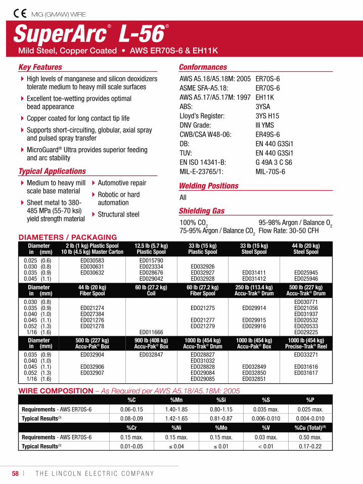
58 ı T H E L I N C O L N E L E C T R I C C O M P A N Y
SuperArc ® L-56 ®
Welding Positions
Typical Applications
All
Medium to heavy mill scale base material
Sheet metal to 380- 485 MPa (55-70 ksi) yield strength material
Automotive repair
Robotic or hard automation
Structural steel
High levels of manganese and silicon deoxidizers tolerate medium to heavy mill scale surfaces
Excellent toe-wetting provides optimal bead appearance
Copper coated for long contact tip life
Supports short-circuiting, globular, axial spray and pulsed spray transfer
MicroGuard® Ultra provides superior feeding and arc stability
Conformances
Shielding Gas100% CO275-95% Argon / Balance CO2
95-98% Argon / Balance O2Flow Rate: 30-50 CFH
Key FeaturesAWS A5.18/A5.18M: 2005ASME SFA-A5.18:AWS A5.17/A5.17M: 1997ABS:Lloyd’s Register:DNV Grade:CWB/CSA W48-06:DB:TUV:EN ISO 14341-B:MIL-E-23765/1:
ER70S-6ER70S-6EH11K3YSA3YS H15III YMSER49S-6EN 440 G3Si1 EN 440 G3Si1G 49A 3 C S6MIL-70S-6
DIAMETERS / PACKAGINGDiameter 2 lb (1 kg) Plastic Spool
10 lb (4.5 kg) Master Carton12.5 lb (5.7 kg)Plastic Spool
33 lb (15 kg)Plastic Spool
33 lb (15 kg)Steel Spool
44 lb (20 kg)Steel Spoolin (mm)
0.0250.0300.0350.045
(0.6)(0.8)(0.9)(1.1)
ED030583 ED030631 ED030632
ED015790 ED023334 ED028676ED029042
ED032926ED032927ED032928
ED031411 ED031412
ED025945 ED025946
Diameter 44 lb (20 kg)Fiber Spool
60 lb (27.2 kg)Coil
60 lb (27.2 kg)Fiber Spool
250 lb (113.4 kg)Accu-Trak® Drum
500 lb (227 kg)Accu-Trak® Drumin (mm)
0.0300.0350.0400.0450.0521/16
(0.8)(0.9)(1.0)(1.1)(1.3)(1.6)
ED021274 ED027384 ED021276 ED021278
ED011666
EDO21275
EDO21277 EDO21279
ED029914
ED029915 ED029916
ED030771ED021056 ED031937ED020532 ED020533 ED029225
Diameter 500 lb (227 kg)Accu-Pak® Box
900 lb (408 kg)Accu-Pak® Box
1000 lb (454 kg)Accu-Trak® Drum
1000 lb (454 kg)Accu-Pak® Box
1000 lb (454 kg)Precise-Trak® Reelin (mm)
0.0350.0400.0450.0521/16
(0.9)(1.0)(1.1)(1.3)(1.6)
ED032904
ED032906ED032907
ED032847 EDO28827 EDO31032 EDO28828 EDO29084 EDO29085
ED032849ED032850ED032851
EDO33271
ED031616ED031617
WIRE COMPOSITION%C %Mn %Si %S %P
Requirements - AWS ER70S-6 0.06-0.15 1.40-1.85 0.80-1.15 0.035 max. 0.025 max.
Typical Results(3) 0.08-0.09 1.42-1.65 0.81-0.87 0.006-0.010 0.004-0.010
%Cr %Ni %Mo %V %Cu (Total)(4)
Requirements - AWS ER70S-6 0.15 max. 0.15 max. 0.15 max. 0.03 max. 0.50 max.
Typical Results(3) 0.01-0.05 0.04 0.01 < 0.01 0.17-0.22
MIG (GMAW) WIRE
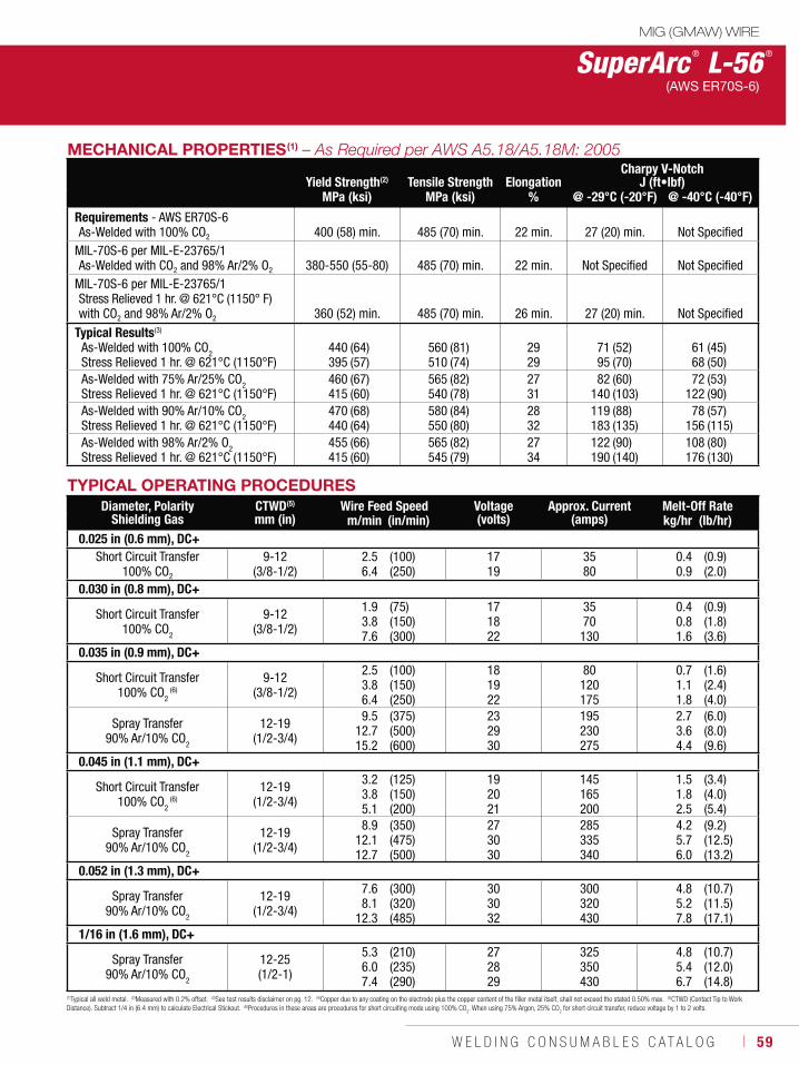
W E L D I N G C O N S U M A B L E S C A T A L O G ı 59
MECHANICAL PROPERTIES(1)
Yield Strength(2) Tensile Strength ElongationCharpy V-Notch
J (ft•lbf)MPa (ksi) MPa (ksi) % @ -29°C (-20°F) @ -40°C (-40°F)
Requirements - AWS ER70S-6As-Welded with 100% CO2 400 (58) min. 485 (70) min. 22 min. 27 (20) min. Not Specified
MIL-70S-6 per MIL-E-23765/1As-Welded with CO2 and 98% Ar/2% O2 380-550 (55-80) 485 (70) min. 22 min. Not Specified Not Specified
MIL-70S-6 per MIL-E-23765/1Stress Relieved 1 hr. @ 621°C (1150° F)with CO2 and 98% Ar/2% O2 360 (52) min. 485 (70) min. 26 min. 27 (20) min. Not Specified
Typical Results(3)
As-Welded with 100% CO2Stress Relieved 1 hr. @ 621°C (1150°F)
440395
(64)(57)
560510
(81)(74)
2929
7195
(52)(70)
6168
(45)(50)
As-Welded with 75% Ar/25% CO2Stress Relieved 1 hr. @ 621°C (1150°F)
460415
(67)(60)
565540
(82)(78)
2731
82140
(60)(103)
72122
(53)(90)
As-Welded with 90% Ar/10% CO2Stress Relieved 1 hr. @ 621°C (1150°F)
470440
(68)(64)
580550
(84)(80)
2832
119183
(88)(135)
78156
(57)(115)
As-Welded with 98% Ar/2% O2Stress Relieved 1 hr. @ 621°C (1150°F)
455415
(66)(60)
565545
(82)(79)
2734
122190
(90)(140)
108176
(80)(130)
(1)Typical all weld metal. (2)Measured with 0.2% offset. (3)See test results disclaimer on pg. 12. (4)Copper due to any coating on the electrode plus the copper content of the filler metal itself, shall not exceed the stated 0.50% max. (5)CTWD (Contact Tip to Work Distance). Subtract 1/4 in (6.4 mm) to calculate Electrical Stickout. (6)Procedures in these areas are procedures for short circuiting mode using 100% CO
2. When using 75% Argon, 25% CO
2 for short circuit transfer, reduce voltage by 1 to 2 volts.
TYPICAL OPERATING PROCEDURESDiameter, Polarity
Shielding GasCTWD(5)
mm (in)Wire Feed Speed Voltage
(volts)Approx. Current
(amps)Melt-Off Rate
m/min (in/min) kg/hr (lb/hr)0.025 in (0.6 mm), DC+
Short Circuit Transfer100% CO2
9-12 (3/8-1/2)
2.56.4
(100)(250)
1719
3580
0.40.9
(0.9)(2.0)
0.030 in (0.8 mm), DC+
Short Circuit Transfer100% CO2
9-12 (3/8-1/2)
1.93.87.6
(75)(150)(300)
171822
3570
130
0.40.81.6
(0.9)(1.8)(3.6)
0.035 in (0.9 mm), DC+
Short Circuit Transfer100% CO2
(6)9-12
(3/8-1/2)
2.53.86.4
(100)(150)(250)
181922
80120175
0.71.11.8
(1.6)(2.4)(4.0)
Spray Transfer90% Ar/10% CO2
12-19 (1/2-3/4)
9.512.715.2
(375)(500)(600)
232930
195230275
2.73.64.4
(6.0)(8.0)(9.6)
0.045 in (1.1 mm), DC+
Short Circuit Transfer100% CO2
(6)12-19
(1/2-3/4)
3.23.85.1
(125)(150)(200)
192021
145165200
1.51.82.5
(3.4)(4.0)(5.4)
Spray Transfer90% Ar/10% CO2
12-19 (1/2-3/4)
8.912.112.7
(350)(475)(500)
273030
285335340
4.25.76.0
(9.2)(12.5)(13.2)
0.052 in (1.3 mm), DC+
Spray Transfer90% Ar/10% CO2
12-19 (1/2-3/4)
7.68.1
12.3
(300)(320)(485)
303032
300320430
4.85.27.8
(10.7)(11.5)(17.1)
1/16 in (1.6 mm), DC+
Spray Transfer90% Ar/10% CO2
12-25 (1/2-1)
5.36.07.4
(210)(235)(290)
272829
325350430
4.85.46.7
(10.7)(12.0)(14.8)
MIG (GMAW) WIRE
SuperArc ® L-56 ®
(AWS ER70S-6)

60 ı T H E L I N C O L N E L E C T R I C C O M P A N Y
SuperArc ® L-59 ®
Welding Positions
Typical ApplicationsAll
Robotic or hard automation
Automotive
Pipeline & Offshore
Pressure vessels
Heavy fabrication
Alternative to metal-cored wire
High deposition rates similar to metal-cored wire
Minimal spatter
Engineered alloy system enhances silicon island management
Copper coated for long contact tip life
Fast travel speeds
MicroGuard® Ultra provides superior feeding and arc stability
Conformances
Shielding Gas100% CO275-95% Argon / Balance CO295-98% Argon / Balance O2Flow Rate: 30 - 50 CFH
Key FeaturesAWS A5.18/A5.18M: 2005ASME SFA-A5.18:ABS:DNV Grade:BV Grade:CWB/CSA W48-06:EN ISO 14341-B:
ER70S-6ER70S-63YSA (100 C02 & Mixed)III YMS H5 (Mixed)SA3YHHH (Mixed)ER49S-6G 49A 3 C S6
DIAMETERS / PACKAGINGDiameter 44 lb (20 kg)
Fiber Spool44 lb (20 kg)Steel Spool
60 lb (27.2 kg)Fiber Spool
500 lb (227 kg)Accu-Pak® Boxin (mm)
0.0350.0400.0450.0521/16
(0.9)(1.0)(1.1)(1.3)(1.6)
ED033033 ED032366
ED032367ED032368ED032968
ED032814
ED032894ED032895ED032896ED032897
Diameter 900 lb (408 kg)Accu-Pak® Box
1000 lb (454 kg)Accu-Pak® Box
1000 lb (454 kg)Precise-Trak® Reelin (mm)
0.0350.0400.0450.0521/16
(0.9)(1.0)(1.1)(1.3)(1.6)
ED032861
ED032863ED032864ED032865
ED032808ED032809
MIG (GMAW) WIRE
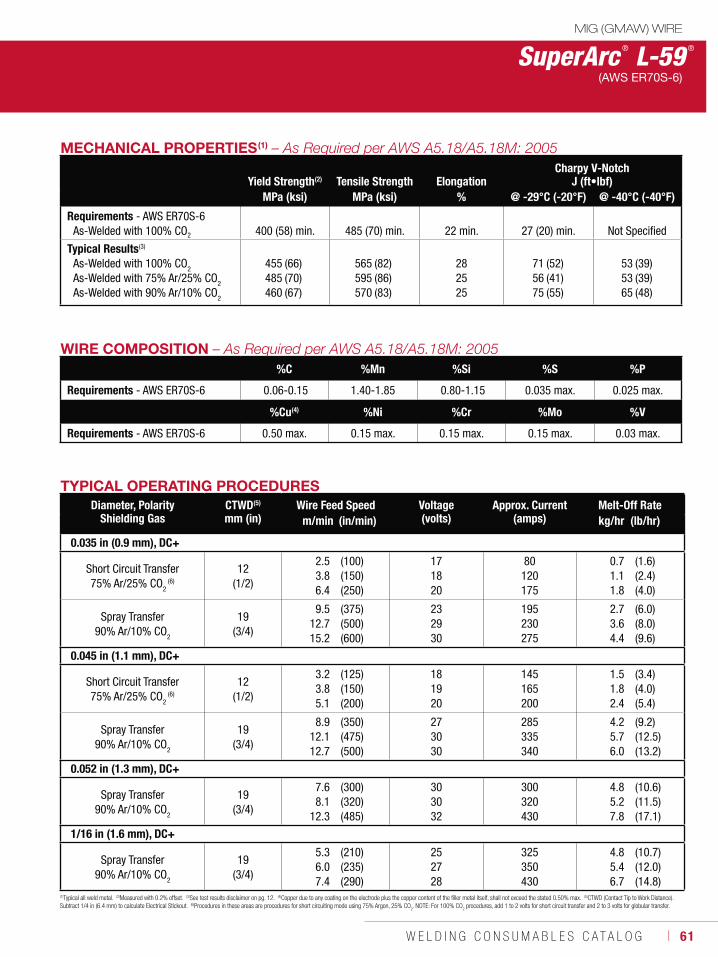
W E L D I N G C O N S U M A B L E S C A T A L O G ı 61
MECHANICAL PROPERTIES(1)
Yield Strength(2) Tensile Strength ElongationCharpy V-Notch
J (ft•lbf)MPa (ksi) MPa (ksi) % @ -29°C (-20°F) @ -40°C (-40°F)
Requirements - AWS ER70S-6As-Welded with 100% CO2
400 (58) min.
485 (70) min.
22 min.
27 (20) min.
Not Specified
Typical Results(3)
As-Welded with 100% CO2
As-Welded with 75% Ar/25% CO2
As-Welded with 90% Ar/10% CO2
455485460
(66)(70)(67)
565595570
(82)(86)(83)
282525
715675
(52)(41)(55)
535365
(39)(39)(48)
WIRE COMPOSITION%C %Mn %Si %S %P
Requirements - AWS ER70S-6 0.06-0.15 1.40-1.85 0.80-1.15 0.035 max. 0.025 max.
%Cu(4) %Ni %Cr %Mo %V
Requirements - AWS ER70S-6 0.50 max. 0.15 max. 0.15 max. 0.15 max. 0.03 max.
(1)Typical all weld metal. (2)Measured with 0.2% offset. (3)See test results disclaimer on pg. 12. (4)Copper due to any coating on the electrode plus the copper content of the filler metal itself, shall not exceed the stated 0.50% max. (5)CTWD (Contact Tip to Work Distance). Subtract 1/4 in (6.4 mm) to calculate Electrical Stickout. (6)Procedures in these areas are procedures for short circuiting mode using 75% Argon, 25% CO
2. NOTE: For 100% CO
2 procedures, add 1 to 2 volts for short circuit transfer and 2 to 3 volts for globular transfer.
TYPICAL OPERATING PROCEDURESDiameter, Polarity
Shielding GasCTWD(5)
mm (in)Wire Feed Speed Voltage
(volts)Approx. Current
(amps)Melt-Off Rate
m/min (in/min) kg/hr (lb/hr)
0.035 in (0.9 mm), DC+
Short Circuit Transfer75% Ar/25% CO2
(6)
12 (1/2)
2.53.86.4
(100)(150)(250)
171820
80120175
0.71.11.8
(1.6)(2.4)(4.0)
Spray Transfer90% Ar/10% CO2
19 (3/4)
9.512.715.2
(375)(500)(600)
232930
195230275
2.73.64.4
(6.0)(8.0)(9.6)
0.045 in (1.1 mm), DC+
Short Circuit Transfer75% Ar/25% CO2
(6)
12 (1/2)
3.23.85.1
(125)(150)(200)
181920
145165200
1.51.82.4
(3.4)(4.0)(5.4)
Spray Transfer90% Ar/10% CO2
19 (3/4)
8.912.112.7
(350)(475)(500)
273030
285335340
4.25.76.0
(9.2)(12.5)(13.2)
0.052 in (1.3 mm), DC+
Spray Transfer90% Ar/10% CO2
19 (3/4)
7.68.1
12.3
(300)(320)(485)
303032
300320430
4.85.27.8
(10.6)(11.5)(17.1)
1/16 in (1.6 mm), DC+
Spray Transfer90% Ar/10% CO2
19 (3/4)
5.36.07.4
(210)(235)(290)
252728
325350430
4.85.46.7
(10.7)(12.0)(14.8)
SuperArc ® L-59 ®
(AWS ER70S-6)
MIG (GMAW) WIRE
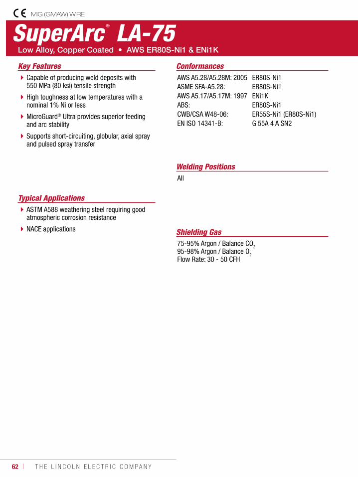
62 ı T H E L I N C O L N E L E C T R I C C O M P A N Y
SuperArc ® LA-75
Welding Positions
Typical Applications
All
ASTM A588 weathering steel requiring good atmospheric corrosion resistance
NACE applications
Capable of producing weld deposits with 550 MPa (80 ksi) tensile strength
High toughness at low temperatures with a nominal 1% Ni or less
MicroGuard® Ultra provides superior feeding and arc stability
Supports short-circuiting, globular, axial spray and pulsed spray transfer
Conformances
Shielding Gas75-95% Argon / Balance CO295-98% Argon / Balance O2Flow Rate: 30 - 50 CFH
Key FeaturesAWS A5.28/A5.28M: 2005ASME SFA-A5.28:AWS A5.17/A5.17M: 1997ABS:CWB/CSA W48-06:EN ISO 14341-B:
ER80S-Ni1ER80S-Ni1ENi1KER80S-Ni1ER55S-Ni1 (ER80S-Ni1)G 55A 4 A SN2
MIG (GMAW) WIRE
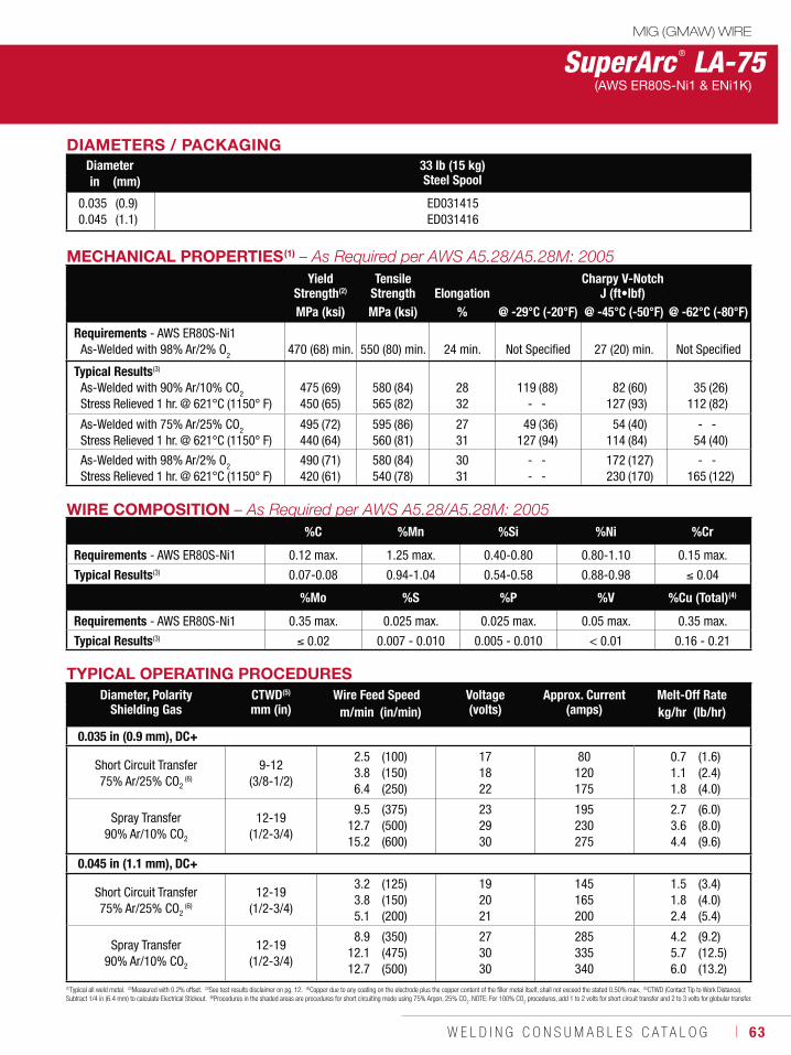
W E L D I N G C O N S U M A B L E S C A T A L O G ı 63
DIAMETERS / PACKAGINGDiameter 33 lb (15 kg)
Steel Spoolin (mm)
0.0350.045
(0.9)(1.1)
ED031415ED031416
MECHANICAL PROPERTIES(1)
Yield Strength(2)
Tensile Strength Elongation
Charpy V-NotchJ (ft•lbf)
MPa (ksi) MPa (ksi) % @ -29°C (-20°F) @ -45°C (-50°F) @ -62°C (-80°F)
Requirements - AWS ER80S-Ni1As-Welded with 98% Ar/2% O2
470 (68) min.
550 (80) min.
24 min.
Not Specified
27 (20) min.
Not Specified
Typical Results(3)
As-Welded with 90% Ar/10% CO2
Stress Relieved 1 hr. @ 621°C (1150° F)475450
(69)(65)
580565
(84)(82)
2832
119-
(88)-
82127
(60)(93)
35112
(26)(82)
As-Welded with 75% Ar/25% CO2
Stress Relieved 1 hr. @ 621°C (1150° F)495440
(72)(64)
595560
(86)(81)
2731
49127
(36)(94)
54114
(40)(84)
- 54
-(40)
As-Welded with 98% Ar/2% O2
Stress Relieved 1 hr. @ 621°C (1150° F)490420
(71)(61)
580540
(84)(78)
3031
- -
--
172230
(127)(170)
- 165
-(122)
SuperArc ® LA-75(AWS ER80S-Ni1 & ENi1K)
WIRE COMPOSITION%C %Mn %Si %Ni %Cr
Requirements - AWS ER80S-Ni1 0.12 max. 1.25 max. 0.40-0.80 0.80-1.10 0.15 max.
Typical Results(3) 0.07-0.08 0.94-1.04 0.54-0.58 0.88-0.98 0.04
%Mo %S %P %V %Cu (Total)(4)
Requirements - AWS ER80S-Ni1 0.35 max. 0.025 max. 0.025 max. 0.05 max. 0.35 max.
Typical Results(3) 0.02 0.007 - 0.010 0.005 - 0.010 < 0.01 0.16 - 0.21
(1)Typical all weld metal. (2)Measured with 0.2% offset. (3)See test results disclaimer on pg. 12. (4)Copper due to any coating on the electrode plus the copper content of the filler metal itself, shall not exceed the stated 0.50% max. (5)CTWD (Contact Tip to Work Distance). Subtract 1/4 in (6.4 mm) to calculate Electrical Stickout. (6)Procedures in the shaded areas are procedures for short circuiting mode using 75% Argon, 25% CO
2. NOTE: For 100% CO
2 procedures, add 1 to 2 volts for short circuit transfer and 2 to 3 volts for globular transfer.
TYPICAL OPERATING PROCEDURESDiameter, Polarity
Shielding GasCTWD(5)
mm (in)Wire Feed Speed Voltage
(volts)Approx. Current
(amps)Melt-Off Rate
m/min (in/min) kg/hr (lb/hr)
0.035 in (0.9 mm), DC+
Short Circuit Transfer75% Ar/25% CO2
(6)
9-12 (3/8-1/2)
2.53.86.4
(100)(150)(250)
171822
80120175
0.71.11.8
(1.6)(2.4)(4.0)
Spray Transfer90% Ar/10% CO2
12-19 (1/2-3/4)
9.512.715.2
(375)(500)(600)
232930
195230275
2.73.64.4
(6.0)(8.0)(9.6)
0.045 in (1.1 mm), DC+
Short Circuit Transfer75% Ar/25% CO2
(6)
12-19 (1/2-3/4)
3.23.85.1
(125)(150)(200)
192021
145165200
1.51.82.4
(3.4)(4.0)(5.4)
Spray Transfer90% Ar/10% CO2
12-19 (1/2-3/4)
8.912.112.7
(350)(475)(500)
273030
285335340
4.25.76.0
(9.2)(12.5)(13.2)
MIG (GMAW) WIRE
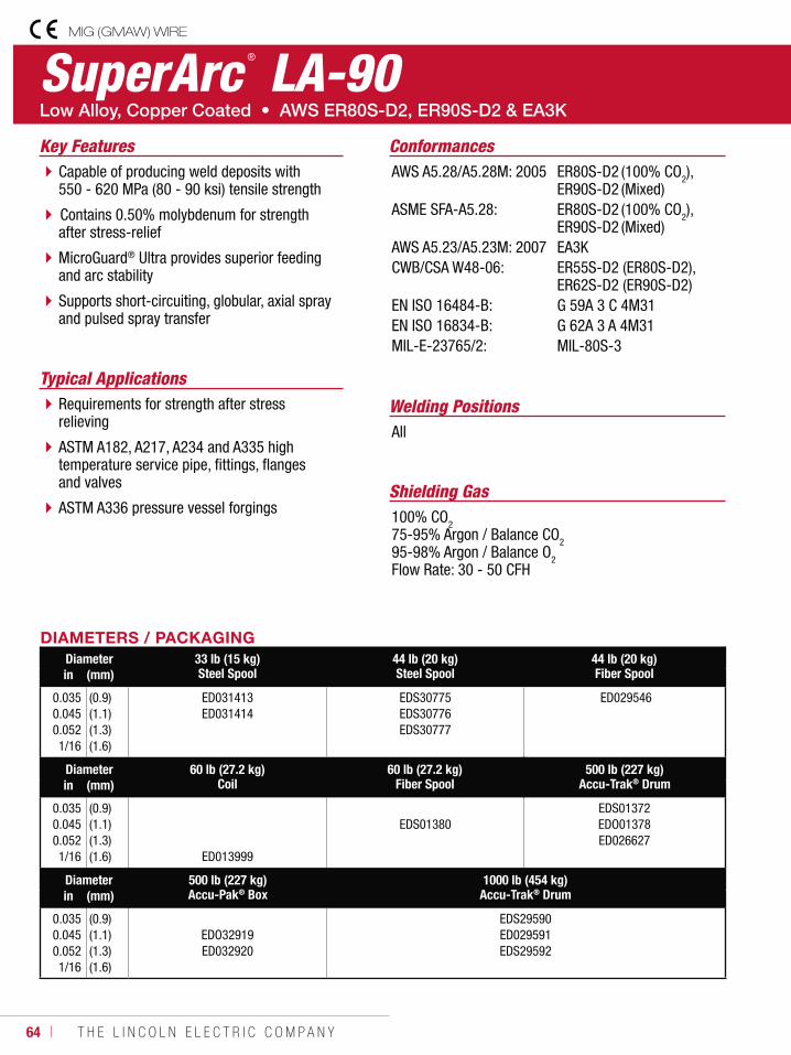
64 ı T H E L I N C O L N E L E C T R I C C O M P A N Y
SuperArc ® LA-90
Welding Positions
Typical Applications
All
Requirements for strength after stress relieving
ASTM A182, A217, A234 and A335 high temperature service pipe, fittings, flanges and valves
ASTM A336 pressure vessel forgings
Capable of producing weld deposits with 550 - 620 MPa (80 - 90 ksi) tensile strength
Contains 0.50% molybdenum for strength after stress-relief
MicroGuard® Ultra provides superior feeding and arc stability
Supports short-circuiting, globular, axial spray and pulsed spray transfer
Conformances
Shielding Gas100% CO275-95% Argon / Balance CO295-98% Argon / Balance O2Flow Rate: 30 - 50 CFH
Key FeaturesAWS A5.28/A5.28M: 2005
ASME SFA-A5.28:
AWS A5.23/A5.23M: 2007CWB/CSA W48-06:
EN ISO 16484-B:EN ISO 16834-B:MIL-E-23765/2:
ER80S-D2 (100% CO2), ER90S-D2 (Mixed)ER80S-D2 (100% CO2), ER90S-D2 (Mixed)EA3KER55S-D2 (ER80S-D2), ER62S-D2 (ER90S-D2)G 59A 3 C 4M31G 62A 3 A 4M31MIL-80S-3
DIAMETERS / PACKAGINGDiameter 33 lb (15 kg)
Steel Spool44 lb (20 kg)Steel Spool
44 lb (20 kg)Fiber Spoolin (mm)
0.0350.0450.0521/16
(0.9)(1.1)(1.3)(1.6)
ED031413 ED031414
EDS30775 EDS30776 EDS30777
ED029546
Diameter 60 lb (27.2 kg)Coil
60 lb (27.2 kg)Fiber Spool
500 lb (227 kg)Accu-Trak® Drumin (mm)
0.0350.0450.0521/16
(0.9)(1.1)(1.3)(1.6) ED013999
EDS01380 EDS01372EDO01378ED026627
Diameter 500 lb (227 kg)Accu-Pak® Box
1000 lb (454 kg)Accu-Trak® Drumin (mm)
0.0350.0450.0521/16
(0.9)(1.1)(1.3)(1.6)
EDO32919ED032920
EDS29590ED029591EDS29592
MIG (GMAW) WIRE
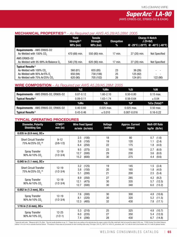
W E L D I N G C O N S U M A B L E S C A T A L O G ı 65
SuperArc ® LA-90(AWS ER80S-D2, ER90S-D2 & EA3K)
MECHANICAL PROPERTIES(1)
Yield Strength(2)
Tensile Strength Elongation
Charpy V-NotchJ (ft•lbf)
MPa (ksi) MPa (ksi) % @ -29°C (-20°F) @ -40°C (-40°F)
Requirements - AWS ER80S-D2As-Welded with 100% CO2 470 (68) min. 550 (80) min. 17 min. 27 (20) min. Not Specified
AWS ER90S-D2As-Welded with 95-99% Ar/Balance O2 540 (78) min. 620 (90) min. 17 min. 27 (20) min. Not Specified
Typical Results(3)
As-Welded with 100% CO2
As-Welded with 95% Ar/5% O2
As-Welded with 75% Ar/25% CO2
560650620
(81)(94)(90)
655730705
(95)(106)(102)
232526
36125124
(26)(92)(91)
--
122
--
(90)
WIRE COMPOSITION%C %Mn %Si %Ni
Requirements - AWS ER80S-D2, ER90S-D2 0.07-0.12 1.60-2.10 0.50-0.80 0.15 max.
Typical Results(3) 0.09-0.11 1.63-1.74 0.56-0.64 0.04
%Mo %S %P %Cu (Total)(4)
Requirements - AWS ER80S-D2, ER90S-D2 0.40-0.60 0.025 max. 0.025 max. 0.50 max.
Typical Results(3) 0.43-0.46 0.010 0.007-0.016 0.16-0.22
(1)Typical all weld metal. (2)Measured with 0.2% offset. (3)See test results disclaimer on pg. 12. (4)Copper due to any coating on the electrode plus the copper content of the filler metal itself, shall not exceed the stated 0.50% max. (5)CTWD (Contact Tip to Work Distance). Subtract 1/4 in (6.4 mm) to calculate Electrical Stickout. (6)Procedures in these areas are procedures for short circuiting mode using 75% Argon, 25% CO
2. NOTE: For 100% CO
2 procedures, add 1 to 2 volts for short circuit transfer and 2 to 3 volts for globular transfer.
TYPICAL OPERATING PROCEDURESDiameter, Polarity
Shielding GasCTWD(5)
mm (in)Wire Feed Speed Voltage
(volts)Approx. Current
(amps)Melt-Off Rate
m/min (in/min) kg/hr (lb/hr)
0.035 in (0.9 mm), DC+
Short Circuit Transfer75% Ar/25% CO2
(6)
9-12 (3/8-1/2)
2.53.86.4
(100)(150)(250)
181922
80120175
0.71.11.8
(1.6)(2.4)(4.0)
Spray Transfer90% Ar/10% CO2
12-19 (1/2-3/4)
9.512.715.2
(375)(500)(600)
232930
195230275
2.73.64.4
(6.0)(8.0)(9.6)
0.045 in (1.1 mm), DC+
Short Circuit Transfer75% Ar/25% CO2
(6)
12-19 (1/2-3/4)
3.23.85.1
(125)(150)(200)
192021
145165200
1.51.82.5
(3.4)(4.0)(5.4)
Spray Transfer90% Ar/10% CO2
12-19 (1/2-3/4)
8.912.112.7
(350)(475)(500)
273030
285335340
4.25.76.0
(9.2)(12.5)(13.2)
0.052 in (1.3 mm), DC+
Spray Transfer90% Ar/10% CO2
12-19 (1/2-3/4)
7.68.1
12.3
(300)(320)(485)
303032
300320430
4.85.27.8
(10.6)(11.5)(17.1)
1/16 in (1.6 mm), DC+
Spray Transfer90% Ar/10% CO2
12-25 (1/2-1)
5.36.07.4
(210)(235)(290)
252728
325350430
4.85.46.7
(10.7)(12.0)(14.8)
MIG (GMAW) WIRE
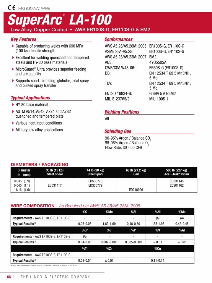
66 ı T H E L I N C O L N E L E C T R I C C O M P A N Y
SuperArc ® LA-100
Welding Positions
Typical Applications
All
HY-80 base material
ASTM A514, A543, A724 and A782 quenched and tempered plate
Various heat input conditions
Military low alloy applications
Capable of producing welds with 690 MPa (100 ksi) tensile strength
Excellent for welding quenched and tempered steels and HY-80 base materials
MicroGuard® Ultra provides superior feeding and arc stability
Supports short-circuiting, globular, axial spray and pulsed spray transfer
Conformances
Shielding Gas90-95% Argon / Balance CO295-98% Argon / Balance O2Flow Rate: 30 - 50 CFH
Key FeaturesAWS A5.28/A5.28M: 2005ASME SFA-A5.28:AWS A5.23/A5.23M: 2007ABS:CWB/CSA W48-06:DB:
TUV:
EN ISO 16834-B:MIL-E-23765/2:
ER100S-G, ER110S-GER100S-G, ER110S-G EM24YQ550SAER69S-G (ER100S-G)EN 12534 T 69 5 Mn3Ni1, 5 MoEN 12534 T 69 5 Mn3Ni1, 5 MoG 69A 5 A N3M2MIL-100S-1
DIAMETERS / PACKAGINGDiameter 33 lb (15 kg)
Steel Spool44 lb (20 kg)Steel Spool
60 lb (27.2 kg)Coil
500 lb (227 kg)Accu-Trak® Drumin (mm)
0.0350.0451/16
(0.9)(1.1)(1.6)
ED031417EDS30778EDS30779
ED010996
ED031445EDS01162
WIRE COMPOSITION%C %Mn %Si %Ni %Mo
Requirements - AWS ER100S-G, ER110S-G - - - (A) (A)
Typical Results(3) 0.05-0.06 1.63-1.69 0.46-0.50 1.88-1.96 0.43-0.45
%Cr %S %P %V %Al
Requirements - AWS ER100S-G, ER110S-G (A) - - - -
Typical Results(3) 0.04-0.06 0.002-0.005 0.005-0.009 0.01 0.01
%Ti %Zr %Cu
Requirements - AWS ER100S-G, ER110S-G - - -
Typical Results(3) 0.03-0.04 0.01 0.11-0.14(A) Must have the minimum of one or more of the following: 0.50% Ni, 0.30% Cr, or 0.20% Mo.
MIG (GMAW) WIRE
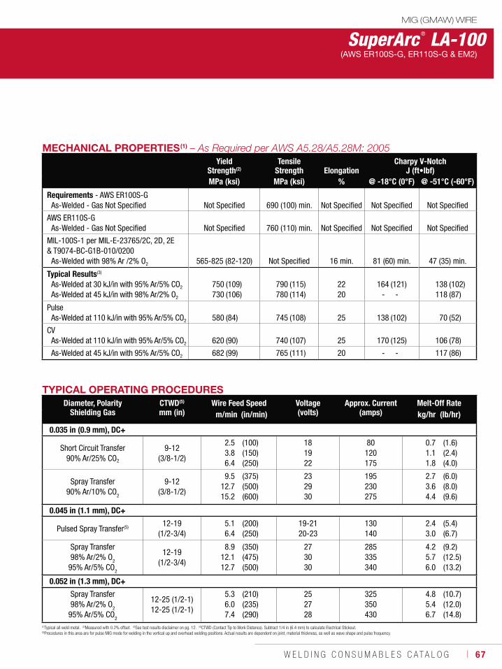
W E L D I N G C O N S U M A B L E S C A T A L O G ı 67
SuperArc ® LA-100(AWS ER100S-G, ER110S-G & EM2)
MECHANICAL PROPERTIES(1)
Yield Strength(2)
Tensile Strength Elongation
Charpy V-NotchJ (ft•lbf)
MPa (ksi) MPa (ksi) % @ -18°C (0°F) @ -51°C (-60°F)
Requirements - AWS ER100S-GAs-Welded - Gas Not Specified
Not Specified
690 (100) min.
Not Specified
Not Specified
Not Specified
AWS ER110S-GAs-Welded - Gas Not Specified Not Specified 760 (110) min. Not Specified Not Specified Not Specified
MIL-100S-1 per MIL-E-23765/2C, 2D, 2E & T9074-BC-G1B-010/0200
As-Welded with 98% Ar /2% O2 565-825 (82-120) Not Specified 16 min. 81 (60) min. 47 (35) min.
Typical Results(3)
As-Welded at 30 kJ/in with 95% Ar/5% CO2
As-Welded at 45 kJ/in with 98% Ar/2% O2
750730
(109)(106)
790780
(115)(114)
2220
164-
(121)-
138118
(102)(87)
PulseAs-Welded at 110 kJ/in with 95% Ar/5% CO2 580 (84) 745 (108) 25 138 (102) 70 (52)
CVAs-Welded at 110 kJ/in with 95% Ar/5% CO2 620 (90) 740 (107) 25 170 (125) 106 (78)
As-Welded at 45 kJ/in with 95% Ar/5% CO2 682 (99) 765 (111) 20 - - 117 (86)
(1)Typical all weld metal. (2)Measured with 0.2% offset. (3)See test results disclaimer on pg. 12. (4)CTWD (Contact Tip to Work Distance). Subtract 1/4 in (6.4 mm) to calculate Electrical Stickout. (5)Procedures in this area are for pulse MIG mode for welding in the vertical up and overhead welding positions. Actual results are dependent on joint, material thickness, as well as wave shape and pulse frequency.
TYPICAL OPERATING PROCEDURESDiameter, Polarity
Shielding GasCTWD(5)
mm (in)Wire Feed Speed Voltage
(volts)Approx. Current
(amps)Melt-Off Rate
m/min (in/min) kg/hr (lb/hr)
0.035 in (0.9 mm), DC+
Short Circuit Transfer90% Ar/25% CO2
9-12 (3/8-1/2)
2.53.86.4
(100)(150)(250)
181922
80120175
0.71.11.8
(1.6)(2.4)(4.0)
Spray Transfer90% Ar/10% CO2
9-12 (3/8-1/2)
9.512.715.2
(375)(500)(600)
232930
195230275
2.73.64.4
(6.0)(8.0)(9.6)
0.045 in (1.1 mm), DC+
Pulsed Spray Transfer(5) 12-19 (1/2-3/4)
5.16.4
(200)(250)
19-2120-23
130140
2.43.0
(5.4)(6.7)
Spray Transfer98% Ar/2% O2
95% Ar/5% CO2
12-19 (1/2-3/4)
8.912.112.7
(350)(475)(500)
273030
285335340
4.25.76.0
(9.2)(12.5)(13.2)
0.052 in (1.3 mm), DC+
Spray Transfer98% Ar/2% O2
95% Ar/5% CO2
12-25 (1/2-1)12-25 (1/2-1)
5.36.07.4
(210)(235)(290)
252728
325350430
4.85.46.7
(10.7)(12.0)(14.8)
MIG (GMAW) WIRE
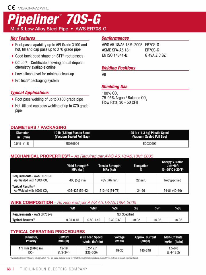
68 ı T H E L I N C O L N E L E C T R I C C O M P A N Y
Pipeliner ® 70S-G
Welding Positions
Typical Applications
All
Root pass welding of up to X100 grade pipe
Hot, fill and cap pass welding of up to X70 grade pipe
Root pass capability up to API Grade X100 and hot, fill and cap pass up to X70 grade pipe
Good back bead shape on STT® root passes
Q2 Lot® - Certificate showing actual deposit chemistry available online
Low silicon level for minimal clean-up
ProTech® packaging system
Conformances
Shielding Gas100% CO275-95% Argon / Balance CO2Flow Rate: 30 - 50 CFH
Key FeaturesAWS A5.18/A5.18M: 2005ASME SFA-A5.18:EN ISO 14341-B:
ER70S-GER70S-GG 49A Z C SZ
DIAMETERS / PACKAGINGDiameter 10 lb (4.5 kg) Plastic Spool
(Vacuum Sealed Foil Bag)25 lb (11.3 kg) Plastic Spool (Vacuum Sealed Foil Bag)in (mm)
0.045 (1.1) ED030904 ED030905
WIRE COMPOSITION%C %Mn %Si %S %P %Cu
Requirements - AWS ER70S-G Not Specified
Typical Results(3) 0.05-0.15 0.80-1.40 0.30-0.60 0.02 0.02 0.02
MECHANICAL PROPERTIES(1)
Yield Strength(2)
MPa (ksi)Tensile Strength
MPa (ksi)Elongation
%
Charpy V-NotchJ (ft•lbf)
@ -29°C (-20°F)
Requirements - AWS ER70S-GAs-Welded with 100% CO2
400 (58) min. 485 (70) min.
22 min. Not Specified
Typical Results(3)
As-Welded with 100% CO2 405-425 (59-62) 510-40 (74-78) 24-26 54-81 (40-60)
TYPICAL OPERATING PROCEDURESDiameter, Polarity
CTWD(4)
mm (in)Wire Feed Speed Voltage
(volts)Approx. Current
(amps)Melt-Off Rate
m/min (in/min) kg/hr (lb/hr)
1.1 mm (0.045 in), DC+
12-19 (1/2-3/4)
3.2-12.7 (125-500)
19-30 145-3401.5-6.0
(3.4-13.2)(1)Typical all weld metal. (2)Measured with 0.2% offset. (3)See test results disclaimer on pg. 12. (4)CTWD (Contact Tip to Work Distance). Subtract 1/4 in. (6.4 mm) to calculate Electrical Stickout.
MIG (GMAW) WIRE
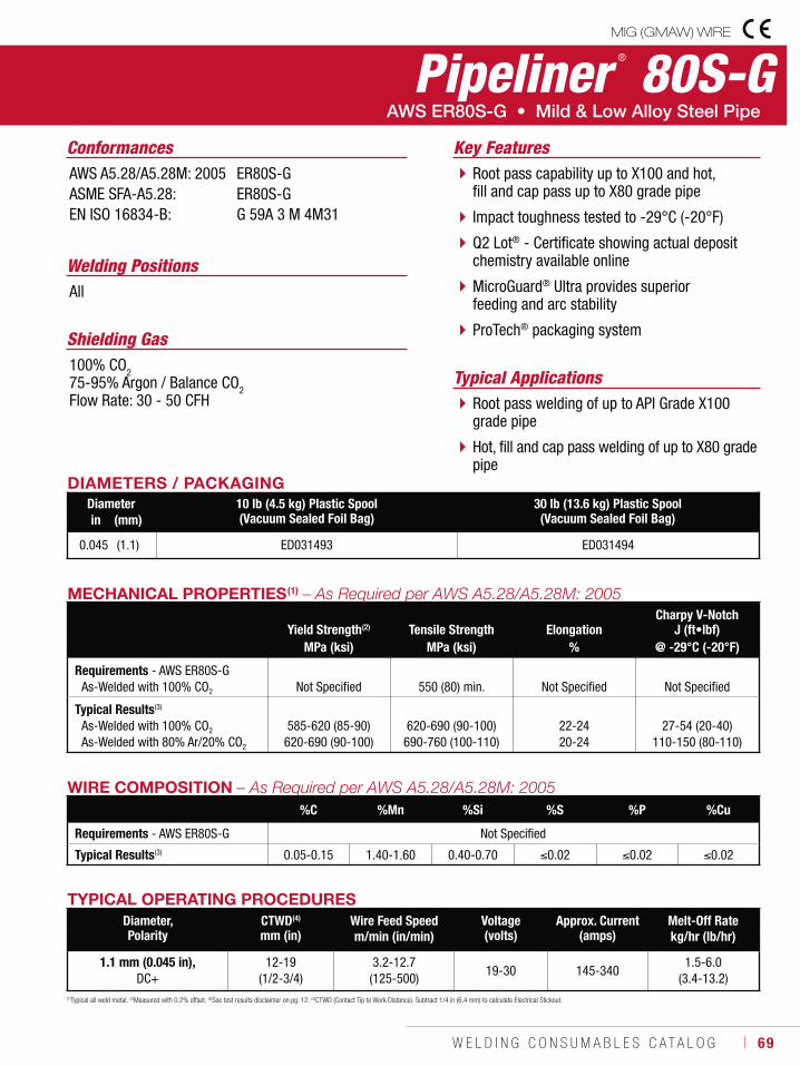
W E L D I N G C O N S U M A B L E S C A T A L O G ı 69
Pipeliner ® 80S-G
Welding Positions
Typical Applications
All
Root pass welding of up to API Grade X100 grade pipe
Hot, fill and cap pass welding of up to X80 grade pipe
Root pass capability up to X100 and hot, fill and cap pass up to X80 grade pipe
Impact toughness tested to -29°C (-20°F)
Q2 Lot® - Certificate showing actual deposit chemistry available online
MicroGuard® Ultra provides superior feeding and arc stability
ProTech® packaging system
Conformances
Shielding Gas100% CO275-95% Argon / Balance CO2Flow Rate: 30 - 50 CFH
Key FeaturesAWS A5.28/A5.28M: 2005ASME SFA-A5.28:EN ISO 16834-B:
ER80S-GER80S-GG 59A 3 M 4M31
DIAMETERS / PACKAGINGDiameter 10 lb (4.5 kg) Plastic Spool
(Vacuum Sealed Foil Bag)30 lb (13.6 kg) Plastic Spool (Vacuum Sealed Foil Bag)in (mm)
0.045 (1.1) ED031493 ED031494
WIRE COMPOSITION%C %Mn %Si %S %P %Cu
Requirements - AWS ER80S-G Not Specified
Typical Results(3) 0.05-0.15 1.40-1.60 0.40-0.70 0.02 0.02 0.02
MECHANICAL PROPERTIES(1)
Yield Strength(2) Tensile Strength ElongationCharpy V-Notch
J (ft•lbf)MPa (ksi) MPa (ksi) % @ -29°C (-20°F)
Requirements - AWS ER80S-GAs-Welded with 100% CO2
Not Specified
550 (80) min. Not Specified Not Specified
Typical Results(3)
As-Welded with 100% CO2
As-Welded with 80% Ar/20% CO2
585-620 (85-90)620-690 (90-100)
620-690 (90-100)690-760 (100-110)
22-2420-24
27-54 (20-40)110-150 (80-110)
TYPICAL OPERATING PROCEDURESDiameter, Polarity
CTWD(4)
mm (in)Wire Feed Speed Voltage
(volts)Approx. Current
(amps)Melt-Off Rate
m/min (in/min) kg/hr (lb/hr)
1.1 mm (0.045 in), DC+
12-19 (1/2-3/4)
3.2-12.7 (125-500)
19-30 145-3401.5-6.0
(3.4-13.2)(1)Typical all weld metal. (2)Measured with 0.2% offset. (3)See test results disclaimer on pg. 12. (4)CTWD (Contact Tip to Work Distance). Subtract 1/4 in (6.4 mm) to calculate Electrical Stickout.
MIG (GMAW) WIRE
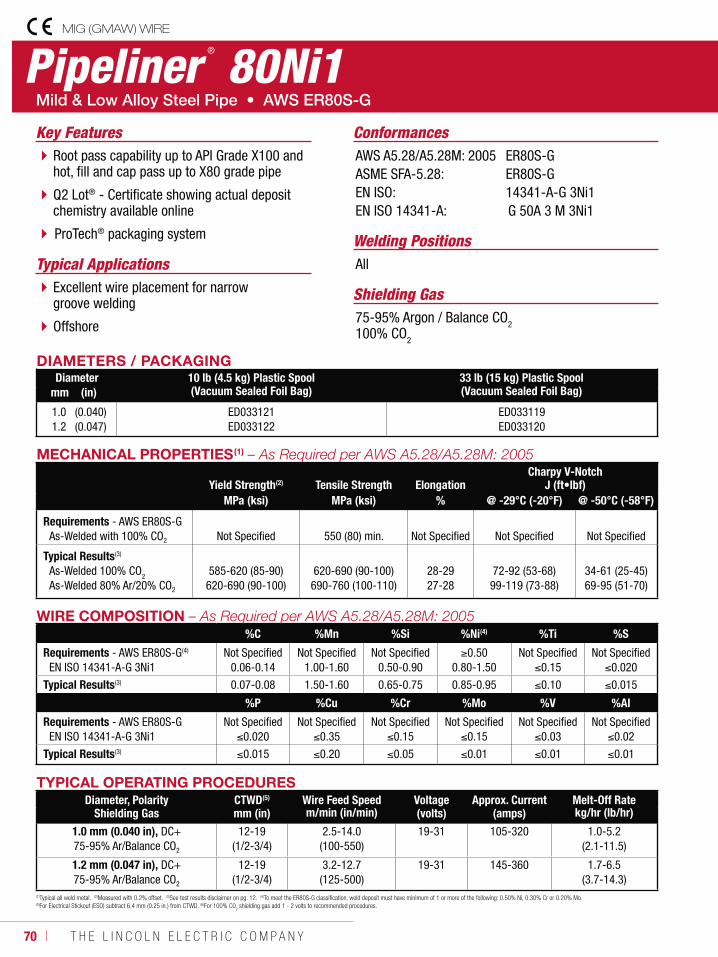
70 ı T H E L I N C O L N E L E C T R I C C O M P A N Y
Pipeliner®
80Ni1
Welding PositionsTypical Applications All
Excellent wire placement for narrow groove welding
Offshore
Root pass capability up to API Grade X100 and hot, fill and cap pass up to X80 grade pipe
Q2 Lot® - Certificate showing actual deposit chemistry available online
ProTech® packaging system
Conformances
Shielding Gas 75-95% Argon / Balance CO2100% CO2
Key FeaturesAWS A5.28/A5.28M: 2005ASME SFA-5.28:EN ISO:EN ISO 14341-A:
ER80S-GER80S-G14341-A-G 3Ni1G 50A 3 M 3Ni1
DIAMETERS / PACKAGINGDiameter 10 lb (4.5 kg) Plastic Spool
(Vacuum Sealed Foil Bag)33 lb (15 kg) Plastic Spool (Vacuum Sealed Foil Bag)mm (in)
1.01.2
(0.040)(0.047)
ED033121ED033122
ED033119ED033120
WIRE COMPOSITION%C %Mn %Si %Ni(4) %Ti %S
Requirements - AWS ER80S-G(4)
EN ISO 14341-A-G 3Ni1Not Specified
0.06-0.14Not Specified
1.00-1.60Not Specified
0.50-0.900.50
0.80-1.50Not Specified
0.15Not Specified
0.020
Typical Results(3) 0.07-0.08 1.50-1.60 0.65-0.75 0.85-0.95 0.10 0.015
%P %Cu %Cr %Mo %V %Al
Requirements - AWS ER80S-GEN ISO 14341-A-G 3Ni1
Not Specified0.020
Not Specified0.35
Not Specified0.15
Not Specified0.15
Not Specified0.03
Not Specified0.02
Typical Results(3) 0.015 0.20 0.05 0.01 0.01 0.01
MECHANICAL PROPERTIES(1)
Yield Strength(2) Tensile Strength ElongationCharpy V-Notch
J (ft•lbf)MPa (ksi) MPa (ksi) % @ -29°C (-20°F) @ -50°C (-58°F)
Requirements - AWS ER80S-GAs-Welded with 100% CO2 Not Specified 550 (80) min. Not Specified Not Specified Not Specified
Typical Results(3)
As-Welded 100% CO2
As-Welded 80% Ar/20% CO2
585-620 (85-90)620-690 (90-100)
620-690 (90-100)690-760 (100-110)
28-2927-28
72-92 (53-68)99-119 (73-88)
34-61 (25-45)69-95 (51-70)
TYPICAL OPERATING PROCEDURESDiameter, Polarity
Shielding GasCTWD(5)
mm (in)Wire Feed Speed Voltage
(volts)Approx. Current
(amps)Melt-Off Rate
m/min (in/min) kg/hr (lb/hr)
1.0 mm (0.040 in), DC+75-95% Ar/Balance CO2
12-19 (1/2-3/4)
2.5-14.0 (100-550)
19-31 105-320 1.0-5.2 (2.1-11.5)
1.2 mm (0.047 in), DC+75-95% Ar/Balance CO2
12-19 (1/2-3/4)
3.2-12.7 (125-500)
19-31 145-360 1.7-6.5 (3.7-14.3)
(1)Typical all weld metal. (2)Measured with 0.2% offset. (3)See test results disclaimer on pg. 12. (4)To meet the ER80S-G classification, weld deposit must have minimum of 1 or more of the following: 0.50% Ni, 0.30% Cr or 0.20% Mo. (5)For Electrical Stickout (ESO) subtract 6.4 mm (0.25 in.) from CTWD. (6)For 100% C0
2 shielding gas add 1 - 2 volts to recommended procedures.
MIG (GMAW) WIRE
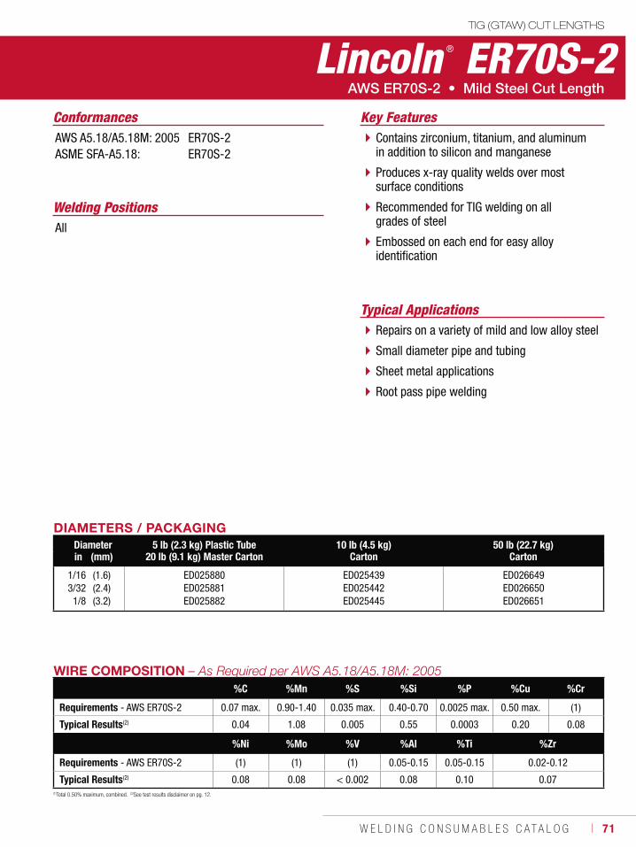
W E L D I N G C O N S U M A B L E S C A T A L O G ı 71
Lincoln ® ER70S-2TIG (GTAW) CUT LENGTHS
Welding Positions
Typical Applications
All
Repairs on a variety of mild and low alloy steel
Small diameter pipe and tubing
Sheet metal applications
Root pass pipe welding
Contains zirconium, titanium, and aluminum in addition to silicon and manganese
Produces x-ray quality welds over most surface conditions
Recommended for TIG welding on all grades of steel
Embossed on each end for easy alloy identification
Conformances Key FeaturesAWS A5.18/A5.18M: 2005ASME SFA-A5.18:
ER70S-2ER70S-2
DIAMETERS / PACKAGINGDiameter 5 lb (2.3 kg) Plastic Tube
20 lb (9.1 kg) Master Carton10 lb (4.5 kg)
Carton50 lb (22.7 kg)
Cartonin (mm)
1/163/321/8
(1.6)(2.4)(3.2)
ED025880ED025881ED025882
ED025439ED025442ED025445
ED026649ED026650ED026651
WIRE COMPOSITION%C %Mn %S %Si %P %Cu %Cr
Requirements - AWS ER70S-2 0.07 max. 0.90-1.40 0.035 max. 0.40-0.70 0.0025 max. 0.50 max. (1)
Typical Results(2) 0.04 1.08 0.005 0.55 0.0003 0.20 0.08
%Ni %Mo %V %Al %Ti %Zr
Requirements - AWS ER70S-2 (1) (1) (1) 0.05-0.15 0.05-0.15 0.02-0.12
Typical Results(2) 0.08 0.08 < 0.002 0.08 0.10 0.07(1)Total 0.50% maximum, combined. (2)See test results disclaimer on pg. 12.
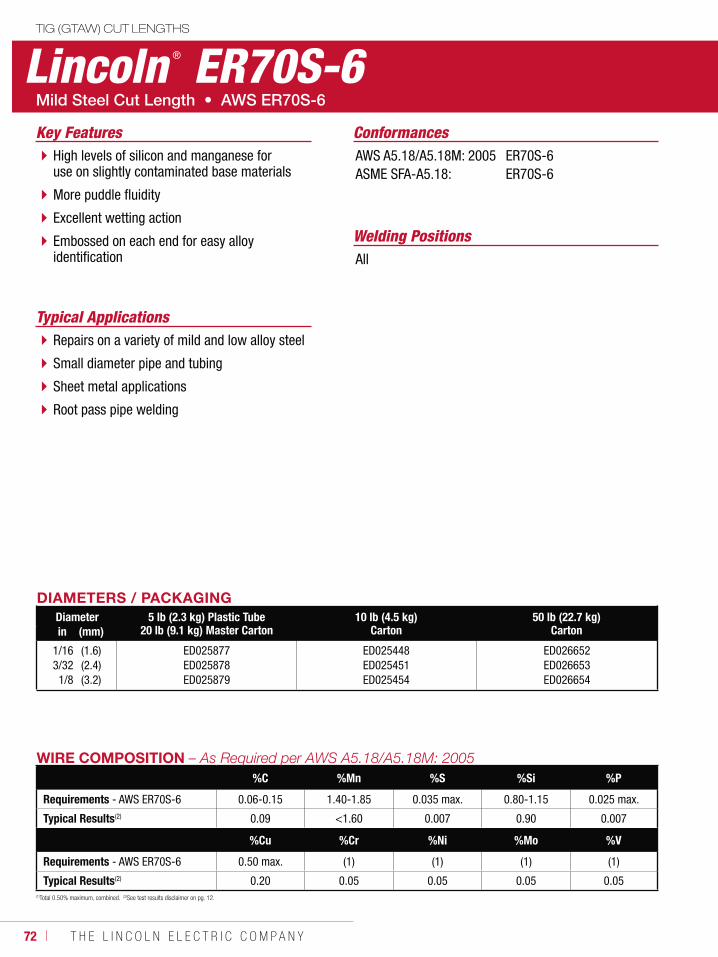
72 ı T H E L I N C O L N E L E C T R I C C O M P A N Y
Lincoln ® ER70S-6TIG (GTAW) CUT LENGTHS
Welding Positions
Typical Applications
All
Repairs on a variety of mild and low alloy steel
Small diameter pipe and tubing
Sheet metal applications
Root pass pipe welding
High levels of silicon and manganese for use on slightly contaminated base materials
More puddle fluidity
Excellent wetting action
Embossed on each end for easy alloy identification
ConformancesKey FeaturesAWS A5.18/A5.18M: 2005ASME SFA-A5.18:
ER70S-6ER70S-6
DIAMETERS / PACKAGINGDiameter 5 lb (2.3 kg) Plastic Tube
20 lb (9.1 kg) Master Carton10 lb (4.5 kg)
Carton50 lb (22.7 kg)
Cartonin (mm)
1/163/321/8
(1.6)(2.4)(3.2)
ED025877ED025878ED025879
ED025448ED025451ED025454
ED026652ED026653ED026654
WIRE COMPOSITION%C %Mn %S %Si %P
Requirements - AWS ER70S-6 0.06-0.15 1.40-1.85 0.035 max. 0.80-1.15 0.025 max.
Typical Results(2) 0.09 <1.60 0.007 0.90 0.007
%Cu %Cr %Ni %Mo %V
Requirements - AWS ER70S-6 0.50 max. (1) (1) (1) (1)
Typical Results(2) 0.20 0.05 0.05 0.05 0.05(1)Total 0.50% maximum, combined. (2)See test results disclaimer on pg. 12.
W E L D I N G C O N S U M A B L E S ı 73
GMAW-C CONSUMABLES
Mild SteelMetalshield® MC-6® .........................................74Metalshield® MC®-706 .....................................76Metalshield® MC-710XL® .................................78
Low AlloyMetalshield® MC®-900 .....................................80Metalshield® MC®-1100 ...................................82
METAL-CORED
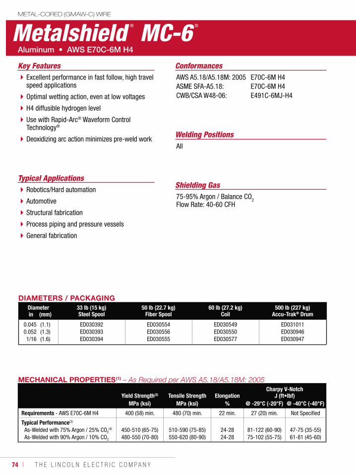
74 ı T H E L I N C O L N E L E C T R I C C O M P A N Y
Metalshield ® MC-6 ®
METAL-CORED (GMAW-C) WIRE
Welding Positions
Typical Applications
All
Robotics/Hard automation
Automotive
Structural fabrication
Process piping and pressure vessels
General fabrication
Excellent performance in fast follow, high travel speed applications
Optimal wetting action, even at low voltages
H4 diffusible hydrogen level
Use with Rapid-Arc® Waveform Control Technology®
Deoxidizing arc action minimizes pre-weld work
Conformances
Shielding Gas75-95% Argon / Balance CO2Flow Rate: 40-60 CFH
Key FeaturesAWS A5.18/A5.18M: 2005ASME SFA-A5.18:CWB/CSA W48-06:
E70C-6M H4E70C-6M H4E491C-6MJ-H4
DIAMETERS / PACKAGINGDiameter 33 lb (15 kg)
Steel Spool50 lb (22.7 kg)
Fiber Spool60 lb (27.2 kg)
Coil500 lb (227 kg)
Accu-Trak® Drumin (mm)
0.0450.0521/16
(1.1)(1.3)(1.6)
ED030392ED030393ED030394
ED030554ED030556ED030555
ED030549ED030550ED030577
ED031011ED030946ED030947
MECHANICAL PROPERTIES(1)
Yield Strength(2) Tensile Strength ElongationCharpy V-Notch
J (ft•lbf)MPa (ksi) MPa (ksi) % @ -29°C (-20°F) @ -40°C (-40°F)
Requirements - AWS E70C-6M H4 400 (58) min. 480 (70) min. 22 min. 27 (20) min. Not Specified
Typical Performance(3)
As-Welded with 75% Argon / 25% CO2(4)
As-Welded with 90% Argon / 10% CO2
450-510 (65-75)480-550 (70-80)
510-590 (75-85)550-620 (80-90)
24-2824-28
81-122 (60-90)75-102 (55-75)
47-75 (35-55)61-81 (45-60)
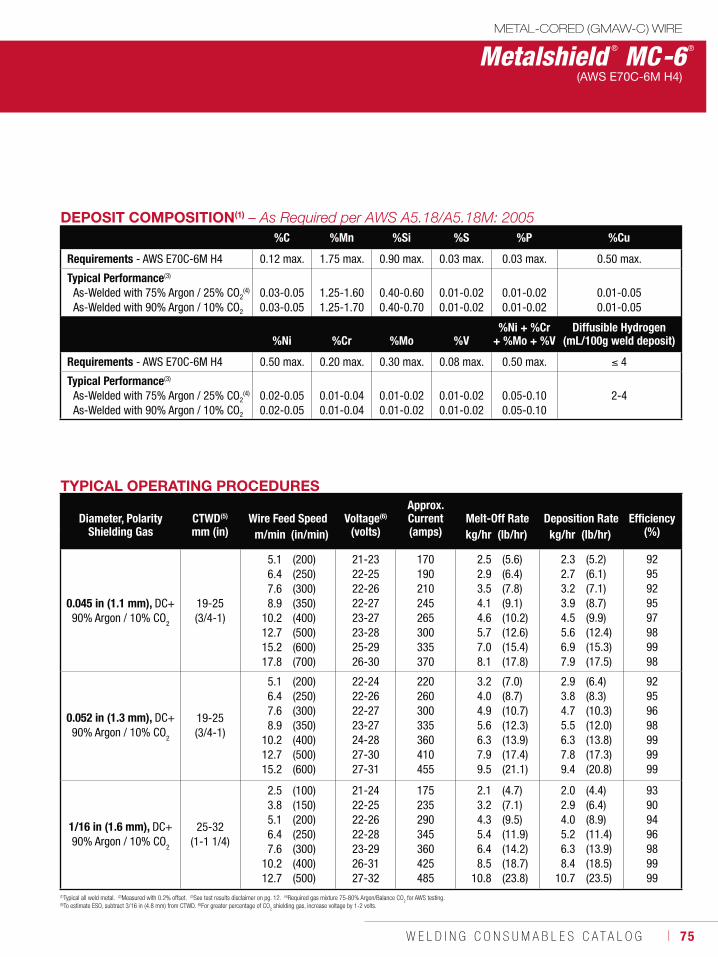
W E L D I N G C O N S U M A B L E S C A T A L O G ı 75
Metalshield ® MC-6®
METAL-CORED (GMAW-C) WIRE
(AWS E70C-6M H4)
DEPOSIT COMPOSITION(1)
%C %Mn %Si %S %P %Cu
Requirements - AWS E70C-6M H4 0.12 max. 1.75 max. 0.90 max. 0.03 max. 0.03 max. 0.50 max.
Typical Performance(3)
As-Welded with 75% Argon / 25% CO2(4)
As-Welded with 90% Argon / 10% CO2
0.03-0.050.03-0.05
1.25-1.601.25-1.70
0.40-0.600.40-0.70
0.01-0.020.01-0.02
0.01-0.020.01-0.02
0.01-0.050.01-0.05
%Ni %Cr %Mo %V%Ni + %Cr
+ %Mo + %VDiffusible Hydrogen
(mL/100g weld deposit)
Requirements - AWS E70C-6M H4 0.50 max. 0.20 max. 0.30 max. 0.08 max. 0.50 max. 4
Typical Performance(3)
As-Welded with 75% Argon / 25% CO2(4)
As-Welded with 90% Argon / 10% CO2
0.02-0.050.02-0.05
0.01-0.040.01-0.04
0.01-0.020.01-0.02
0.01-0.020.01-0.02
0.05-0.100.05-0.10
2-4
(1)Typical all weld metal. (2)Measured with 0.2% offset. (3)See test results disclaimer on pg. 12. (4)Required gas mixture 75-80% Argon/Balance CO2 for AWS testing.
(5)To estimate ESO, subtract 3/16 in (4.8 mm) from CTWD. (6)For greater percentage of CO2 shielding gas, increase voltage by 1-2 volts.
TYPICAL OPERATING PROCEDURES
Diameter, PolarityShielding Gas
CTWD(5)
mm (in)Wire Feed Speed Voltage(6)
(volts)
Approx. Current(amps)
Melt-Off Rate Deposition Rate Efficiency(%)m/min (in/min) kg/hr (lb/hr) kg/hr (lb/hr)
0.045 in (1.1 mm), DC+90% Argon / 10% CO2
19-25(3/4-1)
5.16.47.68.9
10.212.715.217.8
(200)(250)(300)(350)(400)(500)(600)(700)
21-2322-2522-2622-2723-2723-2825-2926-30
170190210245265300335370
2.52.93.54.14.65.77.08.1
(5.6)(6.4)(7.8)(9.1)(10.2)(12.6)(15.4)(17.8)
2.32.73.23.94.55.66.97.9
(5.2)(6.1)(7.1)(8.7)(9.9)(12.4)(15.3)(17.5)
9295929597989998
0.052 in (1.3 mm), DC+90% Argon / 10% CO
2
19-25(3/4-1)
5.16.47.68.9
10.212.715.2
(200)(250)(300)(350)(400)(500)(600)
22-2422-2622-2723-2724-2827-3027-31
220260300335360410455
3.24.04.95.66.37.99.5
(7.0)(8.7)(10.7)(12.3)(13.9)(17.4)(21.1)
2.93.84.75.56.37.89.4
(6.4)(8.3)(10.3)(12.0)(13.8)(17.3)(20.8)
92959698999999
1/16 in (1.6 mm), DC+90% Argon / 10% CO
2
25-32(1-1 1/4)
2.53.85.16.47.6
10.212.7
(100)(150)(200)(250)(300)(400)(500)
21-2422-2522-2622-2823-2926-3127-32
175235290345360425485
2.13.24.35.46.48.5
10.8
(4.7)(7.1)(9.5)(11.9)(14.2)(18.7)(23.8)
2.02.94.05.26.38.4
10.7
(4.4)(6.4)(8.9)(11.4)(13.9)(18.5)(23.5)
93909496989999
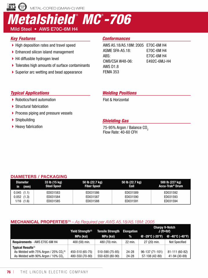
76 ı T H E L I N C O L N E L E C T R I C C O M P A N Y
Metalshield ® MC ®-706METAL-CORED (GMAW-C) WIRE
Welding PositionsTypical ApplicationsFlat & HorizontalRobotics/hard automation
Structural fabrication
Process piping and pressure vessels
Shipbuilding
Heavy fabrication
High deposition rates and travel speed
Enhanced silicon island management
H4 diffusible hydrogen level
Tolerates high amounts of surface contaminants
Superior arc wetting and bead appearance
Conformances
Shielding Gas75-95% Argon / Balance CO2Flow Rate: 40-60 CFH
Key FeaturesAWS A5.18/A5.18M: 2005ASME SFA-A5.18:ABS:CWB/CSA W48-06:AWS D1.8FEMA 353
E70C-6M H4E70C-6M H4E70C-6M H4E492C-6MJ-H4
DIAMETERS / PACKAGINGDiameter 33 lb (15 kg)
Steel Spool50 lb (22.7 kg)
Fiber Spool50 lb (22.7 kg)
Coil500 lb (227 kg)
Accu-Trak® Drumin (mm)
0.0450.0521/16
(1.1)(1.3)(1.6)
ED031583ED031584ED031585
ED031586ED031587ED031588
ED031589ED031590ED031591
ED031592ED031593ED031594
MECHANICAL PROPERTIES(1)
Yield Strength(2) Tensile Strength ElongationCharpy V-Notch
J (ft•lbf)MPa (ksi) MPa (ksi) % @ -29°C (-20°F) @ -40°C (-40°F)
Requirements - AWS E70C-6M H4 400 (58) min. 480 (70) min. 22 min. 27 (20) min. Not Specified
Typical Results(3)
As-Welded with 75% Argon / 25% CO2(4)
As-Welded with 90% Argon / 10% CO2
450-510 (65-75)480-550 (70-80)
510-590 (75-85)550-620 (80-90)
24-2824-28
96-137 (71-101)57-108 (42-80)
81-111 (60-82)41-94 (30-69)
Structural Welding Code Seismic Supplement
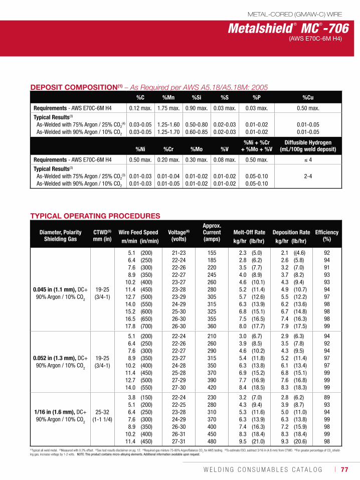
W E L D I N G C O N S U M A B L E S C A T A L O G ı 77
Metalshield ® MC ®-706METAL-CORED (GMAW-C) WIRE
(AWS E70C-6M H4)
DEPOSIT COMPOSITION(1)
%C %Mn %Si %S %P %Cu
Requirements - AWS E70C-6M H4 0.12 max. 1.75 max. 0.90 max. 0.03 max. 0.03 max. 0.50 max.
Typical Results(3)
As-Welded with 75% Argon / 25% CO2(4)
As-Welded with 90% Argon / 10% CO2
0.03-0.05 0.03-0.05
1.25-1.60 1.25-1.70
0.50-0.80 0.60-0.85
0.02-0.030.02-0.03
0.01-0.02 0.01-0.02
0.01-0.05 0.01-0.05
%Ni %Cr %Mo %V%Ni + %Cr
+ %Mo + %VDiffusible Hydrogen
(mL/100g weld deposit)
Requirements - AWS E70C-6M H4 0.50 max. 0.20 max. 0.30 max. 0.08 max. 0.50 max. 4
Typical Results(3)
As-Welded with 75% Argon / 25% CO2(3)
As-Welded with 90% Argon / 10% CO2
0.01-0.03 0.01-0.03
0.01-0.04 0.01-0.05
0.01-0.02 0.01-0.02
0.01-0.02 0.01-0.02
0.05-0.10 0.05-0.10
2-4
TYPICAL OPERATING PROCEDURES
Diameter, PolarityShielding Gas
CTWD(5)
mm (in)Wire Feed Speed Voltage(6)
(volts)
Approx. Current(amps)
Melt-Off Rate Deposition Rate Efficiency(%)m/min (in/min) kg/hr (lb/hr) kg/hr (lb/hr)
0.045 in (1.1 mm), DC+90% Argon / 10% CO2
19-25(3/4-1)
5.16.47.68.9
10.211.412.714.015.216.517.8
(200)(250)(300)(350)(400)(450)(500)(550)(600)(650)(700)
21-23 22-2422-2622-2723-2723-2823-2924-2925-3026-3026-30
155185220245260280305315325355360
2.32.83.54.04.65.25.76.36.87.58.0
(5.0)(6.2)(7.7)(8.9)(10.1)(11.4)(12.6)(13.9)(15.1)(16.5)(17.7)
2.12.63.23.74.34.95.56.26.77.47.9
((4.6)(5.8)(7.0)(8.2)(9.4)(10.7)(12.2)(13.6)(14.8)(16.3)(17.5)
9294919393949798989899
0.052 in (1.3 mm), DC+90% Argon / 10% CO
2
19-25(3/4-1)
5.16.47.68.9
10.211.412.714.0
(200)(250)(300)(350)(400)(450)(500)(550)
22-2422-2622-2723-2724-2825-2827-2927-30
210260290315350370390420
3.03.94.65.46.36.97.78.4
(6.7)(8.5)(10.2)(11.8)(13.8)(15.2)(16.9)(18.5)
2.93.54.35.26.16.87.68.3
(6.3)(7.8)(9.5)(11.4)(13.4)(15.1)(16.8)(18.3)
9492949797999999
1/16 in (1.6 mm), DC+90% Argon / 10% CO
2
25-32(1-1 1/4)
3.85.16.47.68.9
10.211.4
(150)(200)(250)(300)(350)(400)(450)
22-2422-2523-2824-2926-3026-3127-31
230280310370400450480
3.24.35.36.37.48.39.5
(7.0)(9.4)(11.6)(13.9)(16.3)(18.4)(21.0)
2.83.95.06.37.28.39.3
(6.2)(8.7)(11.0)(13.8)(15.9)(18.4)(20.6)
89939499989998
(1)Typical all weld metal. (2)Measured with 0.2% offset. (3)See test results disclaimer on pg. 12. (4)Required gas mixture 75-80% Argon/Balance CO2 for AWS testing. (5)To estimate ESO, subtract 3/16 in (4.8 mm) from CTWD. (6)For greater percentage of CO
2 shield-
ing gas, increase voltage by 1-2 volts. NOTE: This product contains micro-alloying elements. Additional information available upon request.
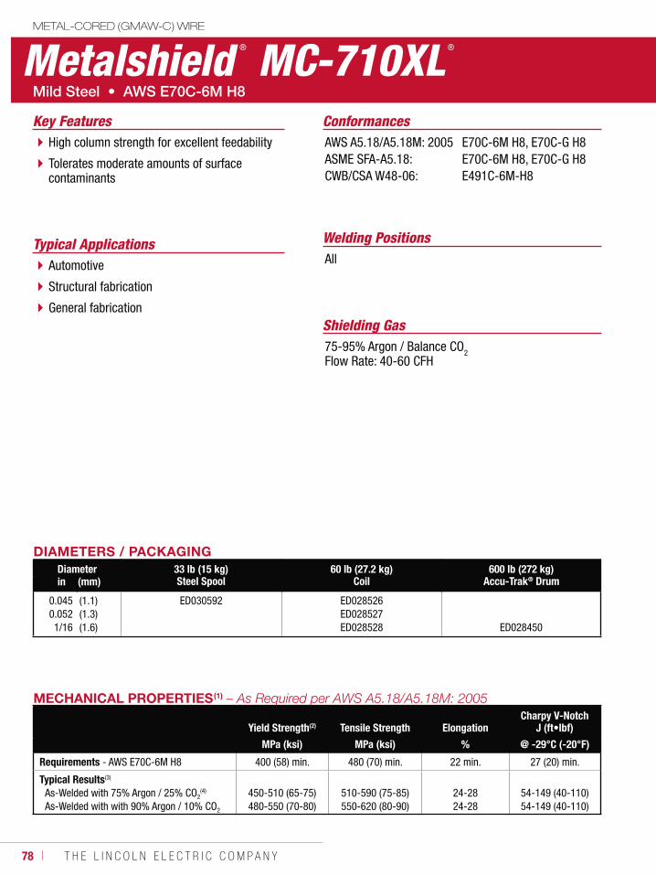
78 ı T H E L I N C O L N E L E C T R I C C O M P A N Y
Metalshield ® MC-710XL ®
METAL-CORED (GMAW-C) WIRE
Welding PositionsTypical ApplicationsAllAutomotive
Structural fabrication
General fabrication
High column strength for excellent feedability
Tolerates moderate amounts of surface contaminants
Conformances
Shielding Gas75-95% Argon / Balance CO2Flow Rate: 40-60 CFH
Key FeaturesAWS A5.18/A5.18M: 2005ASME SFA-A5.18:CWB/CSA W48-06:
E70C-6M H8, E70C-G H8E70C-6M H8, E70C-G H8E491C-6M-H8
DIAMETERS / PACKAGINGDiameter 33 lb (15 kg)
Steel Spool60 lb (27.2 kg)
Coil600 lb (272 kg)
Accu-Trak® Drumin (mm)
0.0450.0521/16
(1.1)(1.3)(1.6)
ED030592 ED028526 ED028527 ED028528 ED028450
MECHANICAL PROPERTIES(1)
Yield Strength(2) Tensile Strength ElongationCharpy V-Notch
J (ft•lbf)
MPa (ksi) MPa (ksi) % @ -29°C (-20°F)
Requirements - AWS E70C-6M H8 400 (58) min. 480 (70) min. 22 min. 27 (20) min.
Typical Results(3)
As-Welded with 75% Argon / 25% CO2(4)
As-Welded with with 90% Argon / 10% CO2
450-510 (65-75)480-550 (70-80)
510-590 (75-85)550-620 (80-90)
24-2824-28
54-149 (40-110)54-149 (40-110)
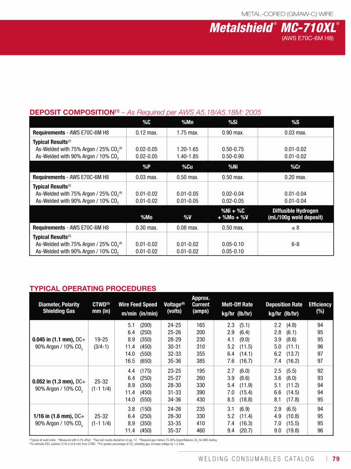
W E L D I N G C O N S U M A B L E S C A T A L O G ı 79
Metalshield ® MC-710XL®
METAL-CORED (GMAW-C) WIRE
(AWS E70C-6M H8)
TYPICAL OPERATING PROCEDURES
Diameter, PolarityShielding Gas
CTWD(5)
mm (in)Wire Feed Speed Voltage(6)
(volts)
Approx. Current(amps)
Melt-Off Rate Deposition Rate Efficiency(%)m/min (in/min) kg/hr (lb/hr) kg/hr (lb/hr)
0.045 in (1.1 mm), DC+90% Argon / 10% CO2
19-25 (3/4-1)
5.16.48.9
11.414.016.5
(200)(250)(350)(450)(550)(650)
24-25 25-26 28-29 30-31 32-33 35-36
165 200 230 310 355 385
2.32.94.15.26.47.6
(5.1)(6.4)(9.0)(11.5)(14.1)(16.7)
2.22.83.95.06.27.4
(4.8)(6.1)(8.6)(11.1)(13.7)(16.2)
949595969797
0.052 in (1.3 mm), DC+90% Argon / 10% CO
2
25-32(1-1 1/4)
4.46.48.9
11.414.0
(175)(250)(350)(450)(550)
23-25 25-27 28-30 31-33 34-36
195 260 330 390 430
2.73.95.47.08.5
(6.0)(8.6)(11.9)(15.4)(18.8)
2.53.65.16.68.1
(5.5)(8.0)(11.2)(14.5)(17.8)
9293949495
1/16 in (1.6 mm), DC+90% Argon / 10% CO
2
25-32(1-1 1/4)
3.86.48.9
11.4
(150)(250)(350)(450)
24-26 28-30 33-35 35-37
235 330 410 460
3.15.27.49.4
(6.9)(11.4)(16.3)(20.7)
2.94.97.09.0
(6.5)(10.8)(15.5)(19.8)
94959596
(1)Typical all weld metal. (2)Measured with 0.2% offset. (3)See test results disclaimer on pg. 12. (4)Required gas mixture 75-80% Argon/Balance CO2 for AWS testing.
(5)To estimate ESO, subtract 3/16 in (4.8 mm) from CTWD. (6)For greater percentage of CO2 shielding gas, increase voltage by 1-2 volts.
DEPOSIT COMPOSITION(1)
%C %Mn %Si %S
Requirements - AWS E70C-6M H8 0.12 max. 1.75 max. 0.90 max. 0.03 max.
Typical Results(3)
As-Welded with 75% Argon / 25% CO2(4)
As-Welded with 90% Argon / 10% CO2
0.02-0.05 0.02-0.05
1.20-1.65 1.40-1.85
0.50-0.75 0.50-0.90
0.01-0.02 0.01-0.02
%P %Cu %Ni %Cr
Requirements - AWS E70C-6M H8 0.03 max. 0.50 max. 0.50 max. 0.20 max.
Typical Results(3)
As-Welded with 75% Argon / 25% CO2(4)
As-Welded with 90% Argon / 10% CO2
0.01-0.02 0.01-0.02
0.01-0.05 0.01-0.05
0.02-0.04 0.02-0.05
0.01-0.04 0.01-0.04
%Mo %V%Ni + %C
+ %Mo + %VDiffusible Hydrogen
(mL/100g weld deposit)
Requirements - AWS E70C-6M H8 0.30 max. 0.08 max. 0.50 max. 8
Typical Results(3)
As-Welded with 75% Argon / 25% CO2(4)
As-Welded with 90% Argon / 10% CO2
0.01-0.02 0.01-0.02
0.01-0.02 0.01-0.02
0.05-0.10 0.05-0.10
6-8
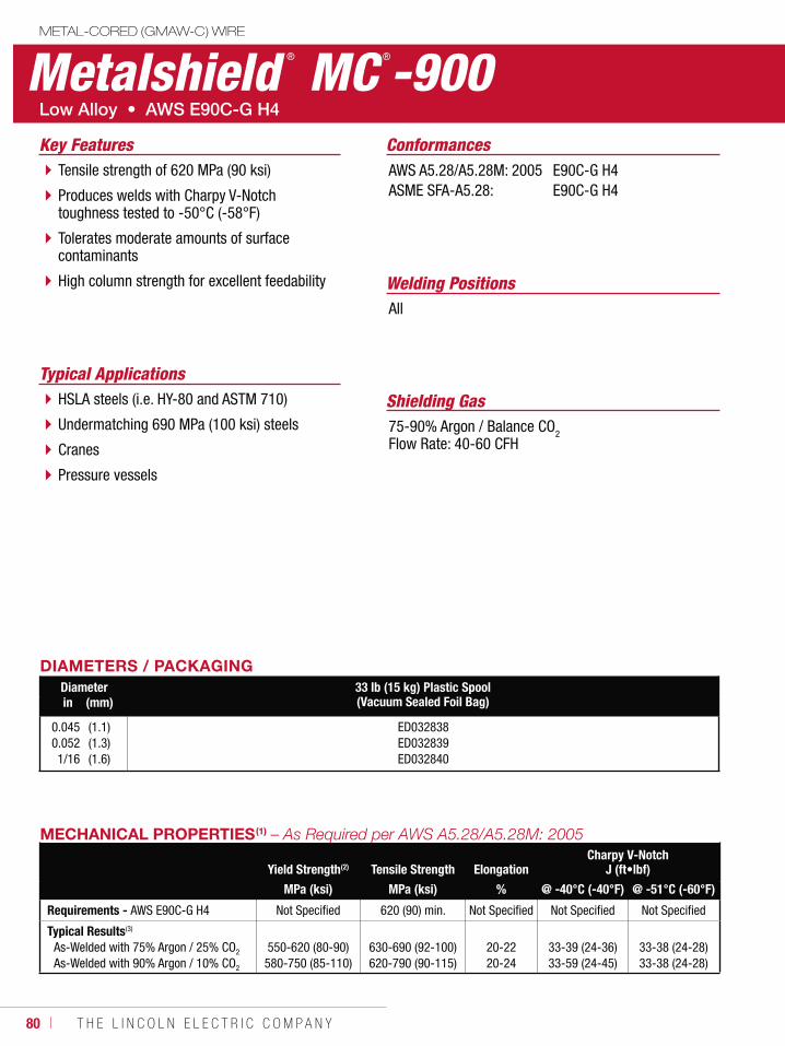
80 ı T H E L I N C O L N E L E C T R I C C O M P A N Y
Metalshield ® MC ®-900METAL-CORED (GMAW-C) WIRE
Welding Positions
Typical Applications
All
HSLA steels (i.e. HY-80 and ASTM 710)
Undermatching 690 MPa (100 ksi) steels
Cranes
Pressure vessels
Tensile strength of 620 MPa (90 ksi)
Produces welds with Charpy V-Notch toughness tested to -50°C (-58°F)
Tolerates moderate amounts of surface contaminants
High column strength for excellent feedability
Conformances
Shielding Gas75-90% Argon / Balance CO2Flow Rate: 40-60 CFH
Key FeaturesAWS A5.28/A5.28M: 2005ASME SFA-A5.28:
E90C-G H4E90C-G H4
DIAMETERS / PACKAGINGDiameter 33 lb (15 kg) Plastic Spool
(Vacuum Sealed Foil Bag)in (mm)
0.0450.0521/16
(1.1)(1.3)(1.6)
ED032838ED032839ED032840
MECHANICAL PROPERTIES(1)
Yield Strength(2) Tensile Strength ElongationCharpy V-Notch
J (ft•lbf)
MPa (ksi) MPa (ksi) % @ -40°C (-40°F) @ -51°C (-60°F)
Requirements - AWS E90C-G H4 Not Specified 620 (90) min. Not Specified Not Specified Not Specified
Typical Results(3)
As-Welded with 75% Argon / 25% CO2
As-Welded with 90% Argon / 10% CO2
550-620 (80-90)580-750 (85-110)
630-690 (92-100)620-790 (90-115)
20-2220-24
33-39 (24-36)33-59 (24-45)
33-38 (24-28)33-38 (24-28)
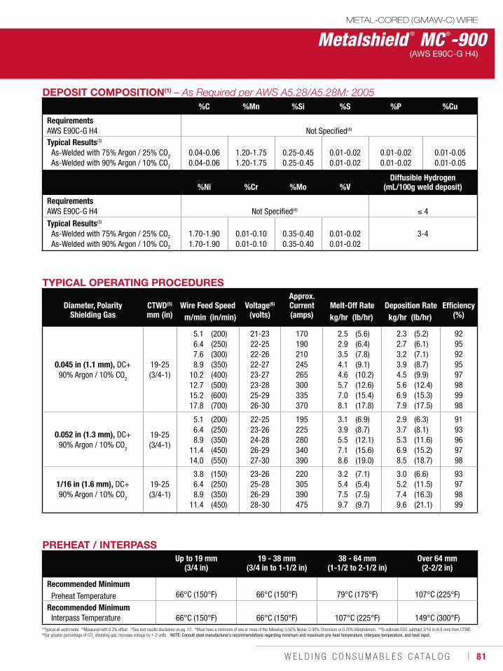
W E L D I N G C O N S U M A B L E S C A T A L O G ı 81
Metalshield ® MC ®-900METAL-CORED (GMAW-C) WIRE
(AWS E90C-G H4)
DEPOSIT COMPOSITION(1)
%C %Mn %Si %S %P %Cu
Requirements AWS E90C-G H4 Not Specified(4)
Typical Results(3)
As-Welded with 75% Argon / 25% CO2
As-Welded with 90% Argon / 10% CO2
0.04-0.06 0.04-0.06
1.20-1.75 1.20-1.75
0.25-0.45 0.25-0.45
0.01-0.02 0.01-0.02
0.01-0.02 0.01-0.02
0.01-0.05 0.01-0.05
%Ni %Cr %Mo %VDiffusible Hydrogen
(mL/100g weld deposit)
Requirements AWS E90C-G H4 Not Specified(4) 4
Typical Results(3)
As-Welded with 75% Argon / 25% CO2
As-Welded with 90% Argon / 10% CO2
1.70-1.901.70-1.90
0.01-0.100.01-0.10
0.35-0.400.35-0.40
0.01-0.02 0.01-0.02
3-4
TYPICAL OPERATING PROCEDURES
Diameter, PolarityShielding Gas
CTWD(5)
mm (in)Wire Feed Speed Voltage(6)
(volts)
Approx. Current(amps)
Melt-Off Rate Deposition Rate Efficiency(%)m/min (in/min) kg/hr (lb/hr) kg/hr (lb/hr)
0.045 in (1.1 mm), DC+90% Argon / 10% CO2
19-25 (3/4-1)
5.16.47.68.9
10.212.715.217.8
(200)(250)(300)(350)(400)(500)(600)(700)
21-2322-2522-2622-2723-2723-2825-2926-30
170190210245265300335370
2.52.93.54.14.65.77.08.1
(5.6)(6.4)(7.8)(9.1)(10.2)(12.6)(15.4)(17.8)
2.32.73.23.94.55.66.97.9
(5.2)(6.1)(7.1)(8.7)(9.9)(12.4)(15.3)(17.5)
9295929597989998
0.052 in (1.3 mm), DC+90% Argon / 10% CO
2
19-25 (3/4-1)
5.16.48.9
11.414.0
(200)(250)(350)(450)(550)
22-2523-2624-2826-2927-30
195225280340390
3.13.95.57.18.6
(6.9)(8.7)(12.1)(15.6)(19.0)
2.93.75.36.98.5
(6.3)(8.1)(11.6)(15.2)(18.7)
9193969798
1/16 in (1.6 mm), DC+90% Argon / 10% CO
2
19-25 (3/4-1)
3.86.48.9
11.4
(150)(250)(350)(450)
23-2625-2826-2928-30
220305390475
3.25.47.59.7
(7.1)(5.4)(7.5)(9.7)
3.05.27.49.6
(6.6)(11.5)(16.3)(21.1)
93979899
(1)Typical all weld metal. (2)Measured with 0.2% offset. (3)See test results disclaimer on pg. 12. (4)Must have a minimum of one or more of the following: 0.50% Nickel, 0.30% Chromium or 0.20% Molybdenum. (5)To estimate ESO, subtract 3/16 in (4.8 mm) from CTWD. (6)For greater percentage of CO
2 shielding gas, increase voltage by 1-2 volts. NOTE: Consult steel manufacturer’s recommendations regarding minimum and maximum pre-heat temperature, interpass temperature, and heat input.
PREHEAT / INTERPASSUp to 19 mm
(3/4 in)19 - 38 mm
(3/4 in to 1-1/2 in)38 - 64 mm
(1-1/2 to 2-1/2 in)Over 64 mm
(2-2/2 in)
Recommended MinimumPreheat Temperature 66°C (150°F) 66°C (150°F) 79°C (175°F) 107°C (225°F)
Recommended MinimumInterpass Temperature 66°C (150°F) 66°C (150°F) 107°C (225°F) 149°C (300°F)
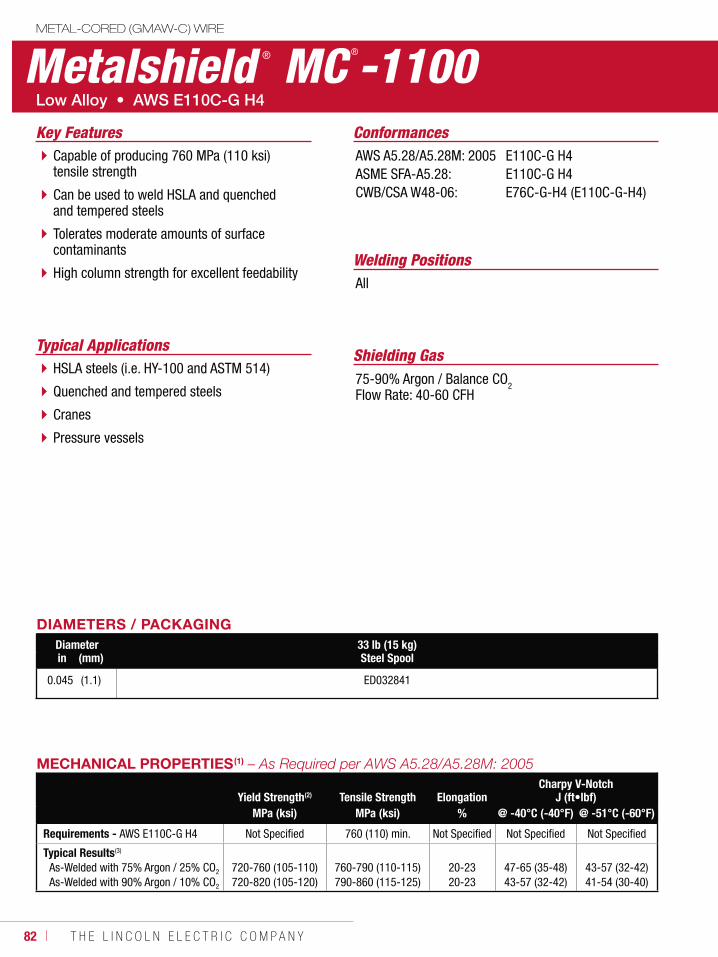
82 ı T H E L I N C O L N E L E C T R I C C O M P A N Y
Metalshield ® MC ®-1100METAL-CORED (GMAW-C) WIRE
Welding Positions
Typical Applications
All
HSLA steels (i.e. HY-100 and ASTM 514)
Quenched and tempered steels
Cranes
Pressure vessels
Capable of producing 760 MPa (110 ksi) tensile strength
Can be used to weld HSLA and quenched and tempered steels
Tolerates moderate amounts of surface contaminants
High column strength for excellent feedability
Conformances
Shielding Gas75-90% Argon / Balance CO2Flow Rate: 40-60 CFH
Key FeaturesAWS A5.28/A5.28M: 2005ASME SFA-A5.28:CWB/CSA W48-06:
E110C-G H4E110C-G H4E76C-G-H4 (E110C-G-H4)
DIAMETERS / PACKAGINGDiameter 33 lb (15 kg)
Steel Spoolin (mm)
0.045 (1.1) ED032841
MECHANICAL PROPERTIES(1)
Yield Strength(2) Tensile Strength ElongationCharpy V-Notch
J (ft•lbf)MPa (ksi) MPa (ksi) % @ -40°C (-40°F) @ -51°C (-60°F)
Requirements - AWS E110C-G H4 Not Specified 760 (110) min. Not Specified Not Specified Not Specified
Typical Results(3)
As-Welded with 75% Argon / 25% CO2
As-Welded with 90% Argon / 10% CO2
720-760 (105-110)720-820 (105-120)
760-790 (110-115)790-860 (115-125)
20-2320-23
47-65 (35-48)43-57 (32-42)
43-57 (32-42)41-54 (30-40)

W E L D I N G C O N S U M A B L E S C A T A L O G ı 83
Metalshield ® MC ®-1100METAL-CORED (GMAW-C) WIRE
(AWS E110C-G H4)
DEPOSIT COMPOSITION(1)
%C %Mn %Si %S %P %Cu
Requirements - AWS E110C-G H4 Not Specified(4)
Typical Results(3)
As-Welded with 75% Argon / 25% CO2
As-Welded with 90% Argon / 10% CO2
0.04-0.06 0.04-0.06
1.75-1.85 1.85-1.95
0.55-0.65 0.60-0.68
0.01-0.02 0.01-0.02
0.01-0.02 0.01-0.02
0.01-0.05 0.01-0.05
%Ni(4) %Cr(4) %Mo(4) %VDiffusible Hydrogen
(mL/100g weld deposit)
Requirements - AWS E110C-G H4 Not Specified(4) 4
Typical Results(3)
As-Welded with 75% Argon / 25% CO2
As-Welded with 90% Argon / 10% CO2
1.70-1.901.70-1.90
0.01-0.100.01-0.10
0.35-0.400.35-0.40
0.01-0.02 0.01-0.02 3-4
TYPICAL OPERATING PROCEDURES
Diameter, PolarityShielding Gas
CTWD(5)
mm (in)Wire Feed Speed Voltage(6)
(volts)
Approx. Current(amps)
Melt-Off Rate Deposition Rate Efficiency(%)m/min (in/min) kg/hr (lb/hr) kg/hr (lb/hr)
0.045 in (1.1 mm), DC+90% Argon / 10% CO2
19-25 (3/4-1)
6.48.9
11.414.016.5
(250)(350)(450)(550)(650)
24-2625-2826-2927-3028-31
180225270310345
2.94.15.26.47.5
(6.4)(9.0)(11.5)(14.1)(16.6)
2.83.95.16.27.4
(6.1)(8.6)(11.2)(13.7)(16.2)
9596979798
(1)Typical all weld metal. (2)Measured with 0.2% offset. (3)See test results disclaimer on pg. 12. (4)Must have a minimum of one or more of the following: 0.50% Nickel, 0.30% Chromium or 0.20% Molybdenum. (5)To estimate ESO, subtract 3/16 in (4.8 mm) from CTWD. (6)For greater percentage of CO
2 shielding gas, increase voltage by 1-2 volts. NOTE: Consult steel manufacturer’s recommendations regarding minimum and maximum pre-heat temperature, interpass temperature, and heat input.
PREHEAT / INTERPASSUp to 19 mm
(3/4 in)19 - 38 mm
(3/4 in to 1-1/2 in)38 - 64 mm
(1-1/2 to 2-1/2 in)Over 64 mm
(2-2/2 in)
Recommended MinimumPreheat Temperature 66°C (150°F) 66°C (150°F) 79°C (175°F) 107°C (225°F)
Recommended MinimumInterpass Temperature 66°C (150°F) 66°C (150°F) 107°C (225°F) 149°C (300°F)
84 ı T H E L I N C O L N E L E C T R I C C O M P A N Y
NotesMETAL-CORED (GMAW-C) CONSUMABLES
W E L D I N G C O N S U M A B L E S ı 85
FCAW-S & FCAW-G CONSUMABLES
Self-Shielded (FCAW-S) WireMild Steel, Flat and HorizontalInnershield® NR®-5 ................................86Innershield® NS-3M ...............................87Innershield® NR®-305 ............................88Innershield® NR®-311 ............................89Innershield® NR®-131 ............................90
Mild Steel, All PositionInnershield® NR®-152 ............................91Innershield® NR®-211-MP ......................92Innershield® NR®-203MP .......................94Innershield® NR®-232 ............................96Innershield® NR®-233 ............................98
Low Alloy, Flat and HorizontalInnershield® NR®-311 Ni ......................100Innershield® NR®-FAB-70 .....................102
Low Alloy, All PositionInnershield® NR®-212 ..........................104Innershield® NR®-203 Nickel (1%) ........106Innershield® NR®-203 Ni C Plus-H ........107Innershield® NR®-440Ni2 .....................108Innershield® NR®-207 ..........................109Pipeliner® NR-207+ ............................110Pipeliner® NR®-208-P ..........................111Pipeliner® NR®-208-XP ........................112Innershield® NR®-208-H .......................113
Gas-Shielded (FCAW-S) WireMild Steel, All PositionUltraCore® 71A85 .................................114UltraCore® 71C .....................................116UltraCore® HD-C ...................................118UltraCore® 71A75 Dual .........................120UltraCore® 712C ...................................122UltraCore® 712A80 ...............................124UltraCore® 712A80-H ...........................126Outershield® 71 Elite ............................128Outershield® 71 Supreme .....................130Outershield® 71M .................................132
Mild Steel, Flat and HorizontalUltraCore® 70C .....................................134UltraCore® 75C .....................................136Outershield® 70 ....................................138Outershield® XLH-70 ............................140
Low Alloy, All PositionUltraCore® 81Ni1A75-H ........................142UltraCore® 81Ni1C-H ............................144UltraCore® 81Ni2A75-H ........................146UltraCore® 81Ni2C-H ............................148UltraCore® 81K2A75-H .........................150UltraCore® 81K2C-H .............................152Outershield® 91K2-H ............................154Pipeliner® 81M .....................................156Pipeliner® G80M ...................................157Pipeliner® G90M ...................................158
FLUX-CORED
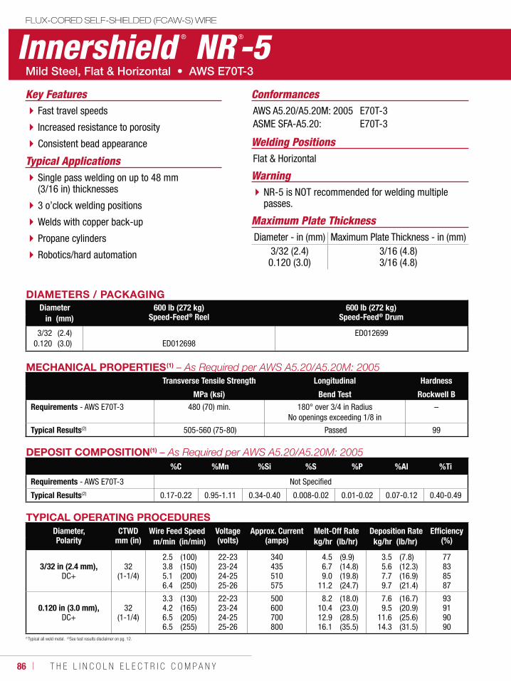
86 ı T H E L I N C O L N E L E C T R I C C O M P A N Y
Innershield ® NR ®-5FLUX-CORED SELF-SHIELDED (FCAW-S) WIRE
Welding Positions
Typical Applications Flat & Horizontal
Single pass welding on up to 48 mm (3/16 in) thicknesses
3 o’clock welding positions
Welds with copper back-up
Propane cylinders
Robotics/hard automation
Fast travel speeds
Increased resistance to porosity
Consistent bead appearance
ConformancesKey FeaturesAWS A5.20/A5.20M: 2005ASME SFA-A5.20:
E70T-3E70T-3
WarningNR-5 is NOT recommended for welding multiple passes.
Maximum Plate ThicknessDiameter - in (mm) Maximum Plate Thickness - in (mm)
3/32 (2.4)0.120 (3.0)
3/16 (4.8)3/16 (4.8)
DIAMETERS / PACKAGINGDiameter 600 lb (272 kg)
Speed-Feed® Reel600 lb (272 kg)
Speed-Feed® Drumin (mm)
3/320.120
(2.4)(3.0) ED012698
ED012699
DEPOSIT COMPOSITION(1)
%C %Mn %Si %S %P %Al %Ti
Requirements - AWS E70T-3 Not Specified
Typical Results(2) 0.17-0.22 0.95-1.11 0.34-0.40 0.008-0.02 0.01-0.02 0.07-0.12 0.40-0.49
MECHANICAL PROPERTIES(1)
Transverse Tensile Strength Longitudinal Hardness
MPa (ksi) Bend Test Rockwell BRequirements - AWS E70T-3 480 (70) min. 180° over 3/4 in Radius
No openings exceeding 1/8 in–
Typical Results(2) 505-560 (75-80) Passed 99
(1)Typical all weld metal. (2)See test results disclaimer on pg. 12.
TYPICAL OPERATING PROCEDURESDiameter,Polarity
CTWDmm (in)
Wire Feed Speed Voltage (volts)
Approx. Current(amps)
Melt-Off Rate Deposition Rate Efficiency(%)m/min (in/min) kg/hr (lb/hr) kg/hr (lb/hr)
3/32 in (2.4 mm),DC+
32 (1-1/4)
2.53.85.16.4
(100)(150)(200)(250)
22-2323-2424-2525-26
340435510575
4.56.79.0
11.2
(9.9)(14.8)(19.8)(24.7)
3.55.67.79.7
(7.8)(12.3)(16.9)(21.4)
77838587
0.120 in (3.0 mm),DC+
32 (1-1/4)
3.34.26.56.5
(130)(165)(205)(255)
22-2323-2424-2525-26
500600700800
8.210.412.916.1
(18.0)(23.0)(28.5)(35.5)
7.69.5
11.614.3
(16.7)(20.9)(25.6)(31.5)
93919090
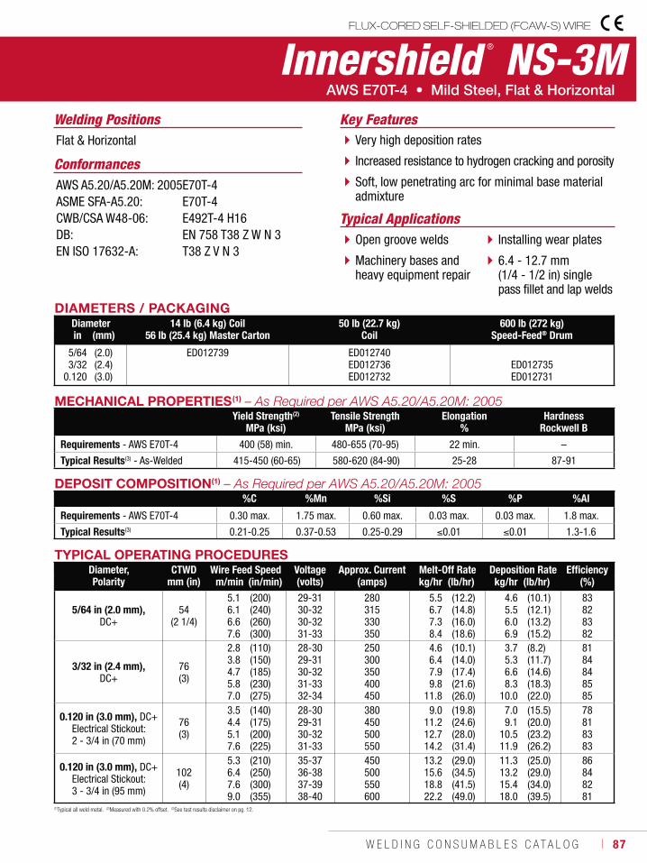
W E L D I N G C O N S U M A B L E S C A T A L O G ı 87
FLUX-CORED SELF-SHIELDED (FCAW-S) WIRE
Innershield ® NS-3MWelding Positions
Typical Applications
Flat & Horizontal
Open groove welds
Machinery bases and heavy equipment repair
Installing wear plates
6.4 - 12.7 mm (1/4 - 1/2 in) single pass fillet and lap welds
Very high deposition rates
Increased resistance to hydrogen cracking and porosity
Soft, low penetrating arc for minimal base material admixture
Conformances
Key Features
AWS A5.20/A5.20M: 2005ASME SFA-A5.20:CWB/CSA W48-06:DB:EN ISO 17632-A:
E70T-4E70T-4E492T-4 H16EN 758 T38 Z W N 3T38 Z V N 3
DIAMETERS / PACKAGINGDiameter 14 lb (6.4 kg) Coil
56 lb (25.4 kg) Master Carton50 lb (22.7 kg)
Coil600 lb (272 kg)
Speed-Feed® Drumin (mm)
5/643/32
0.120
(2.0)(2.4)(3.0)
ED012739 ED012740ED012736ED012732
ED012735ED012731
DEPOSIT COMPOSITION(1)
%C %Mn %Si %S %P %Al
Requirements - AWS E70T-4 0.30 max. 1.75 max. 0.60 max. 0.03 max. 0.03 max. 1.8 max.
Typical Results(3) 0.21-0.25 0.37-0.53 0.25-0.29 0.01 0.01 1.3-1.6
(1)Typical all weld metal. (2)Measured with 0.2% offset. (3)See test results disclaimer on pg. 12.
TYPICAL OPERATING PROCEDURESDiameter, Polarity
CTWDmm (in)
Wire Feed Speed Voltage (volts)
Approx. Current(amps)
Melt-Off Rate Deposition Rate Efficiency(%)m/min (in/min) kg/hr (lb/hr) kg/hr (lb/hr)
5/64 in (2.0 mm),DC+
54 (2 1/4)
5.16.16.67.6
(200)(240)(260)(300)
29-3130-3230-3231-33
280315330350
5.56.77.38.4
(12.2)(14.8)(16.0)(18.6)
4.65.56.06.9
(10.1)(12.1)(13.2)(15.2)
83828382
3/32 in (2.4 mm),DC+
76 (3)
2.83.84.75.87.0
(110)(150)(185)(230)(275)
28-3029-3130-3231-3332-34
250300350400450
4.66.47.99.8
11.8
(10.1)(14.0)(17.4)(21.6)(26.0)
3.75.36.68.3
10.0
(8.2)(11.7)(14.6)(18.3)(22.0)
8184848585
0.120 in (3.0 mm), DC+Electrical Stickout:2 - 3/4 in (70 mm)
76 (3)
3.54.45.17.6
(140)(175)(200)(225)
28-3029-3130-3231-33
380450500550
9.011.212.714.2
(19.8)(24.6)(28.0)(31.4)
7.09.1
10.511.9
(15.5)(20.0)(23.2)(26.2)
78818383
0.120 in (3.0 mm), DC+Electrical Stickout:3 - 3/4 in (95 mm)
102 (4)
5.36.47.69.0
(210)(250)(300)(355)
35-3736-3837-3938-40
450500550600
13.215.618.822.2
(29.0)(34.5)(41.5)(49.0)
11.313.215.418.0
(25.0)(29.0)(34.0)(39.5)
86848281
MECHANICAL PROPERTIES(1)
Yield Strength(2)
MPa (ksi)Tensile Strength
MPa (ksi)Elongation
%Hardness
Rockwell B
Requirements - AWS E70T-4 400 (58) min. 480-655 (70-95) 22 min. –
Typical Results(3) - As-Welded 415-450 (60-65) 580-620 (84-90) 25-28 87-91
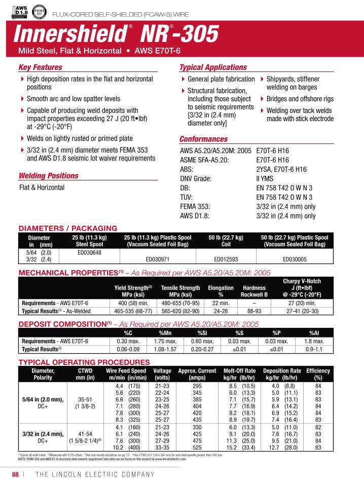
88 ı T H E L I N C O L N E L E C T R I C C O M P A N Y
Innershield ® NR ®-305FLUX-CORED SELF-SHIELDED (FCAW-S) WIRE
Welding Positions
Typical Applications
Flat & Horizontal
General plate fabrication
Structural fabrication, including those subject to seismic requirements [3/32 in (2.4 mm) diameter only]
Shipyards, stiffener welding on barges
Bridges and offshore rigs
Welding over tack welds made with stick electrode
High deposition rates in the flat and horizontal positions
Smooth arc and low spatter levels
Capable of producing weld deposits with impact properties exceeding 27 J (20 ft•lbf) at -29°C (-20°F)
Welds on lightly rusted or primed plate
3/32 in (2.4 mm) diameter meets FEMA 353 and AWS D1.8 seismic lot waiver requirements
Conformances
Key Features
AWS A5.20/A5.20M: 2005ASME SFA-A5.20:ABS:DNV Grade:DB:TUV:FEMA 353:AWS D1.8:
E70T-6 H16E70T-6 H162YSA, E70T-6 H16II YMSEN 758 T42 O W N 3EN 758 T42 O W N 33/32 in (2.4 mm) only3/32 in (2.4 mm) only
DIAMETERS / PACKAGINGDiameter 25 lb (11.3 kg)
Steel Spool25 lb (11.3 kg) Plastic Spool (Vacuum Sealed Foil Bag)
50 lb (22.7 kg)Coil
50 lb (22.7 kg) Plastic Spool (Vacuum Sealed Foil Bag)in (mm)
5/643/32
(2.0)(2.4)
ED030648ED030971 ED012593 ED030005
DEPOSIT COMPOSITION(1)
%C %Mn %Si %S %P %AlRequirements - AWS E70T-6 0.30 max. 1.75 max. 0.60 max. 0.03 max. 0.03 max. 1.8 max.Typical Results(3) 0.06-0.09 1.08-1.57 0.20-0.27 0.01 0.01 0.9-1.1
(1)Typical all weld metal. (2)Measured with 0.2% offset. (3)See test results disclaimer on pg. 12. (4)Use CTWD of 2 1/4 in (54 mm) for wire feed speeds greater than 300 ipm.NOTE: FEMA 353 and AWS D1.8 structural steel seismic supplement test data can be found on this product at www.lincolnelectric.com.
TYPICAL OPERATING PROCEDURESDiameter, Polarity
CTWDmm (in)
Wire Feed Speed Voltage (volts)
Approx. Current(amps)
Melt-Off Rate Deposition Rate Efficiency(%)m/min (in/min) kg/hr (lb/hr) kg/hr (lb/hr)
5/64 in (2.0 mm),DC+
35-51 (1 3/8-2)
4.45.66.67.17.68.3
(175)(220)(260)(280)(300)(325)
21-2322-2423-2524-2625-2725-27
295345385404420435
8.56.07.17.78.28.9
(10.5)(13.3)(15.7)(16.9)(18.1)(19.7)
4.05.05.96.46.97.4
(8.8)(11.1)(13.1)(14.2)(15.2)(16.4)
848383848483
3/32 in (2.4 mm),DC+
41-54 (1 5/8-2 1/4)(4)
4.16.17.6
10.2
(160)(240)(300)(400)
21-2324-2627-2933-35
330425475525
6.09.1
11.315.2
(13.3)(20.0)(25.0)(33.4)
5.07.69.5
12.7
(11.0)(16.7)(21.0)(28.0)
82838483
MECHANICAL PROPERTIES(1)
Yield Strength(2)
Tensile Strength
Elongation
Hardness
Charpy V-NotchJ (ft•lbf)
MPa (ksi) MPa (ksi) % Rockwell B @ -29°C (-20°F)Requirements - AWS E70T-6 400 (58) min. 480-655 (70-95) 22 min. – 27 (20) min.Typical Results(3) - As-Welded 465-535 (68-77) 565-620 (82-90) 24-28 88-93 27-41 (20-30)
Structural Welding Code Seismic Supplement
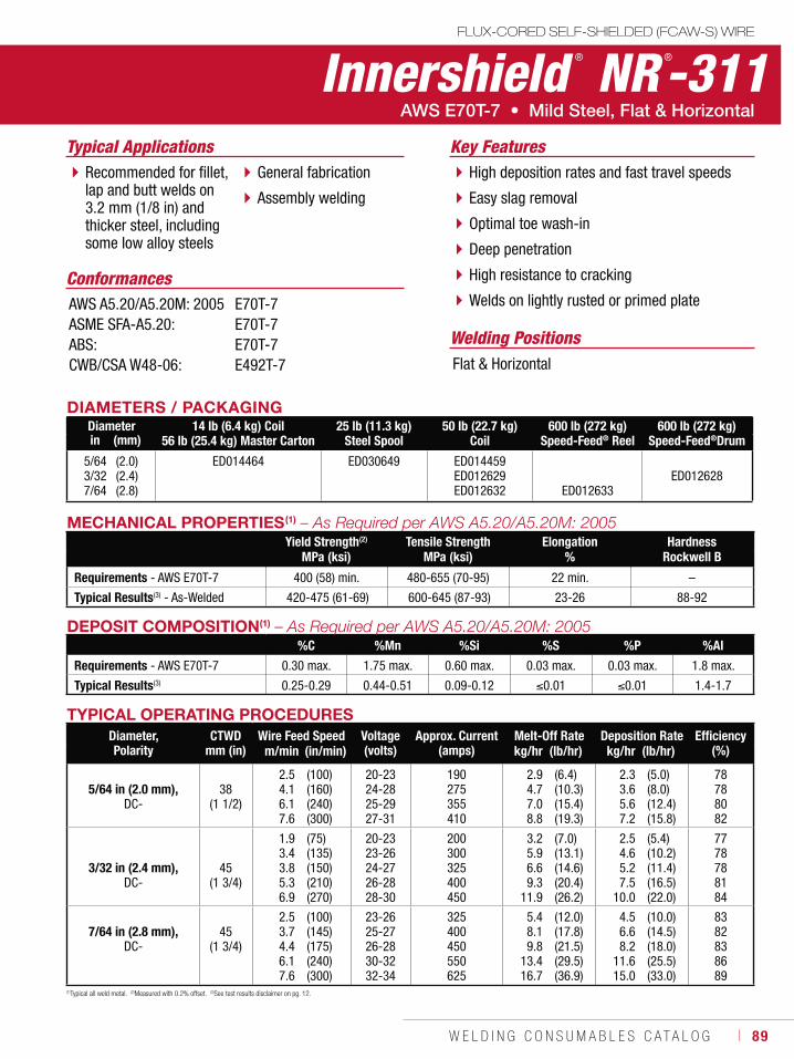
W E L D I N G C O N S U M A B L E S C A T A L O G ı 89
FLUX-CORED SELF-SHIELDED (FCAW-S) WIRE
Innershield ® NR ®-311
Welding Positions
Typical Applications
Flat & Horizontal
Recommended for fillet, lap and butt welds on 3.2 mm (1/8 in) and thicker steel, including some low alloy steels
General fabrication
Assembly welding
High deposition rates and fast travel speeds
Easy slag removal
Optimal toe wash-in
Deep penetration
High resistance to cracking
Welds on lightly rusted or primed plateConformances
Key Features
AWS A5.20/A5.20M: 2005ASME SFA-A5.20:ABS:CWB/CSA W48-06:
E70T-7E70T-7E70T-7E492T-7
DIAMETERS / PACKAGINGDiameter 14 lb (6.4 kg) Coil
56 lb (25.4 kg) Master Carton25 lb (11.3 kg)
Steel Spool50 lb (22.7 kg)
Coil600 lb (272 kg)
Speed-Feed® Reel600 lb (272 kg)
Speed-Feed®Drumin (mm)
5/643/327/64
(2.0)(2.4)(2.8)
ED014464 ED030649 ED014459ED012629ED012632 ED012633
ED012628
DEPOSIT COMPOSITION(1)
%C %Mn %Si %S %P %Al
Requirements - AWS E70T-7 0.30 max. 1.75 max. 0.60 max. 0.03 max. 0.03 max. 1.8 max.
Typical Results(3) 0.25-0.29 0.44-0.51 0.09-0.12 0.01 0.01 1.4-1.7
(1)Typical all weld metal. (2)Measured with 0.2% offset. (3)See test results disclaimer on pg. 12.
MECHANICAL PROPERTIES(1)
Yield Strength(2) Tensile Strength Elongation HardnessMPa (ksi) MPa (ksi) % Rockwell B
Requirements - AWS E70T-7 400 (58) min. 480-655 (70-95) 22 min. –
Typical Results(3) - As-Welded 420-475 (61-69) 600-645 (87-93) 23-26 88-92
TYPICAL OPERATING PROCEDURESDiameter, Polarity
CTWDmm (in)
Wire Feed Speed Voltage (volts)
Approx. Current(amps)
Melt-Off Rate Deposition Rate Efficiency(%)m/min (in/min) kg/hr (lb/hr) kg/hr (lb/hr)
5/64 in (2.0 mm),DC-
38 (1 1/2)
2.54.16.17.6
(100)(160)(240)(300)
20-2324-2825-2927-31
190275355410
2.94.77.08.8
(6.4)(10.3)(15.4)(19.3)
2.33.65.67.2
(5.0)(8.0)(12.4)(15.8)
78788082
3/32 in (2.4 mm),DC-
45 (1 3/4)
1.93.43.85.36.9
(75)(135)(150)(210)(270)
20-2323-2624-2726-2828-30
200300325400450
3.25.96.69.3
11.9
(7.0)(13.1)(14.6)(20.4)(26.2)
2.54.65.27.5
10.0
(5.4)(10.2)(11.4)(16.5)(22.0)
7778788184
7/64 in (2.8 mm),DC-
45 (1 3/4)
2.53.74.46.17.6
(100)(145)(175)(240)(300)
23-2625-2726-2830-3232-34
325400450550625
5.48.19.8
13.416.7
(12.0)(17.8)(21.5)(29.5)(36.9)
4.56.68.2
11.615.0
(10.0)(14.5)(18.0)(25.5)(33.0)
8382838689
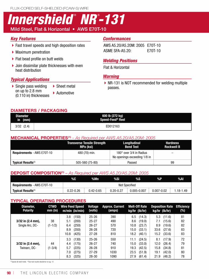
90 ı T H E L I N C O L N E L E C T R I C C O M P A N Y
Innershield ® NR ®-131FLUX-CORED SELF-SHIELDED (FCAW-S) WIRE
Welding Positions
Typical Applications
Flat & Horizontal
Single pass welding on up to 2.8 mm (0.110 in) thicknesses
Sheet metal
Automotive
Fast travel speeds and high deposition rates
Maximum penetration
Flat bead profile on butt welds
Join dissimilar plate thicknesses with even heat distribution
ConformancesKey FeaturesAWS A5.20/A5.20M: 2005ASME SFA-A5.20:
E70T-10E70T-10
DIAMETERS / PACKAGINGDiameter 600 lb (272 kg)
Speed-Feed® Reelin (mm)
3/32 (2.4) ED012163
WarningNR-131 is NOT recommended for welding multiple passes.
DEPOSIT COMPOSITION(1)
%C %Mn %Si %S %P %Al
Requirements - AWS E70T-10 Not Specified
Typical Results(3) 0.22-0.26 0.42-0.65 0.20-0.27 0.005-0.007 0.007-0.02 1.18-1.49
MECHANICAL PROPERTIES(1)
Transverse Tensile StrengthMPa (ksi)
LongitudinalBend Test
HardnessRockwell B
Requirements - AWS E70T-10 480 (70) min. 180° over 3/4 in RadiusNo openings exceeding 1/8 in
–
Typical Results(3) 505-560 (75-80) Passed 99
(1)Typical all weld metal. (2)See test results disclaimer on pg. 12.
TYPICAL OPERATING PROCEDURESDiameter,Polarity
CTWDmm (in)
Wire Feed Speed Voltage (volts)
Approx. Current(amps)
Melt-Off Rate Deposition Rate Efficiency(%)m/min (in/min) kg/hr (lb/hr) kg/hr (lb/hr)
3/32 in (2.4 mm),Single Arc, DC-
38 (1-1/2)
3.85.16.48.9
10.8
(150)(200)(250)(350)(425)
25-2625-2726-2726-2827-28
390490570720810
6.58.6
10.815.018.2
(14.3)(19.0)(23.7)(33.1)(40.1)
5.37.18.9
33.615.2
(11.6)(15.6)(19.6)(27.6)(33.6)
8182828383
3/32 in (2.4 mm),Twinarc, DC-
44 (1-3/4)
3.34.45.77.08.3
(130)(175)(225)(275)(325)
25-2626-2726-2827-2928-30
550740910
10301090
11.115.019.323.527.9
(24.5)(33.0)(42.5)(51.9)(61.4)
8.112.015.819.121.9
(17.9)(26.4)(34.8)(42.0)(48.2)
7279818078
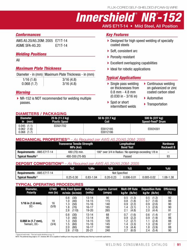
W E L D I N G C O N S U M A B L E S C A T A L O G ı 91
FLUX-CORED SELF-SHIELDED (FCAW-S) WIRE
Innershield ® NR ®-152
Welding Positions
Typical Applications
All
Single pass welding on thicknesses from 0.8 mm - 4.8 mm (0.030 in - 3/16 in)
Spot or short intermittent welds
Continuous welding on galvanized or zinc coated carbon steel
Automotive
Transportation
Designed for high speed welding of specially coated steels
Soft, consistent arc
Porosity resistant
Excellent overlapping capabilities
Ideal for robotic applications
Conformances Key FeaturesAWS A5.20/A5.20M: 2005ASME SFA-A5.20:
E71T-14E71T-14
DIAMETERS / PACKAGINGDiameter 25 lb (11.3 kg)
Plastic Spool50 lb (22.7 kg)
Coil500 lb (227 kg)
Speed-Feed® Drumin (mm)0.0450.0620.068
(1.1)(1.6)(1.7)
EDS01702ED012185ED012186
ED024301
WarningNR-152 is NOT recommended for welding multiple passes.
Maximum Plate ThicknessDiameter - in (mm) Maximum Plate Thickness - in (mm)
1/16 (1.6)0.068 (1.7)
3/16 (4.8)3/16 (4.8)
DEPOSIT COMPOSITION(1)
%C %Mn %Si %S %P %AlRequirements - AWS E71T-14 Not SpecifiedTypical Results(2) 0.25-0.30 0.83-1.04 0.20-0.23 0.006-0.01 0.005-0.02 1.08-1.38
MECHANICAL PROPERTIES(1)
Transverse Tensile StrengthMPa (ksi)
LongitudinalBend Test
HardnessRockwell B
Requirements - AWS E71T-14 480 (70) min. 180° over 3/4 in Radius / No openings exceeding 1/8 in –Typical Results(2) 480-550 (70-80) Passed 93
(1)Typical all weld metal. (2)See test results disclaimer on pg. 12.NOTE: The preferred drag angle is 15°, however, NR-152 is capable of welding at zero drag angle, facilitating easy fixturing in automatic applications.
TYPICAL OPERATING PROCEDURESDiameter,Polarity
CTWDmm (in)
Wire Feed Speed Voltage (volts)
Approx. Current(amps)
Melt-Off Rate Deposition Rate Efficiency(%)m/min (in/min) kg/hr (lb/hr) kg/hr (lb/hr)
1/16 in (1.6 mm),DC-
16 (5/8)
0.81.01.31.82.8
(30)(40)(50)(70)(110)
13-1414-1515-1616-1719-20
90115140185265
0.50.80.91.42.1
(1.3)(1.8)(2.2)(3.1)(4.8)
0.50.70.91.32.0
(1.2)(1.6)(2.0)(2.8)(4.4)
9288909091
0.068 in (1.7 mm),Twinarc, DC-
19 (3/4)
0.81.01.31.52.02.8
(30)(40)(50)(60)(80)(110)
13-1413-1414-1515-1616-1720-21
6895
120145190240
0.70.91.21.41.92.7
(1.6)(2.2)(2.7)(3.3)(4.4)(6.0)
0.60.91.11.31.82.4
(1.4)(1.9)(2.4)(2.9)(3.9)(5.4)
878688878890
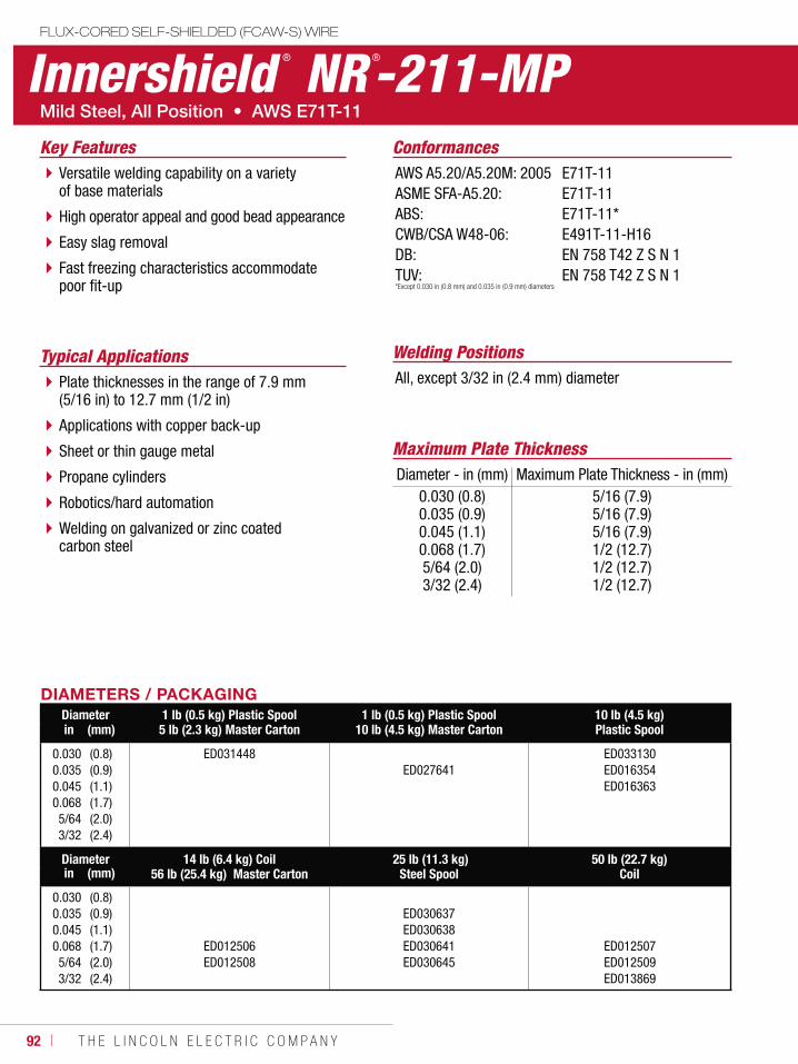
92 ı T H E L I N C O L N E L E C T R I C C O M P A N Y
Innershield ® NR ®-211-MPFLUX-CORED SELF-SHIELDED (FCAW-S) WIRE
Welding PositionsTypical ApplicationsAll, except 3/32 in (2.4 mm) diameterPlate thicknesses in the range of 7.9 mm
(5/16 in) to 12.7 mm (1/2 in)
Applications with copper back-up
Sheet or thin gauge metal
Propane cylinders
Robotics/hard automation
Welding on galvanized or zinc coated carbon steel
Versatile welding capability on a variety of base materials
High operator appeal and good bead appearance
Easy slag removal
Fast freezing characteristics accommodate poor fit-up
ConformancesKey FeaturesAWS A5.20/A5.20M: 2005ASME SFA-A5.20:ABS:CWB/CSA W48-06: DB: TUV:
E71T-11E71T-11E71T-11* E491T-11-H16 EN 758 T42 Z S N 1 EN 758 T42 Z S N 1
DIAMETERS / PACKAGINGDiameter 1 lb (0.5 kg) Plastic Spool
5 lb (2.3 kg) Master Carton1 lb (0.5 kg) Plastic Spool
10 lb (4.5 kg) Master Carton10 lb (4.5 kg)Plastic Spoolin (mm)
0.0300.0350.0450.0685/643/32
(0.8)(0.9)(1.1)(1.7)(2.0)(2.4)
ED031448ED027641
ED033130ED016354ED016363
Diameter 14 lb (6.4 kg) Coil56 lb (25.4 kg) Master Carton
25 lb (11.3 kg)Steel Spool
50 lb (22.7 kg)Coilin (mm)
0.0300.0350.0450.0685/643/32
(0.8)(0.9)(1.1)(1.7)(2.0)(2.4)
ED012506ED012508
ED030637ED030638ED030641ED030645
ED012507ED012509ED013869
*Except 0.030 in (0.8 mm) and 0.035 in (0.9 mm) diameters
Maximum Plate ThicknessDiameter - in (mm) Maximum Plate Thickness - in (mm)
0.030 (0.8)0.035 (0.9)0.045 (1.1)0.068 (1.7)5/64 (2.0)3/32 (2.4)
5/16 (7.9)5/16 (7.9)5/16 (7.9)1/2 (12.7)1/2 (12.7)1/2 (12.7)
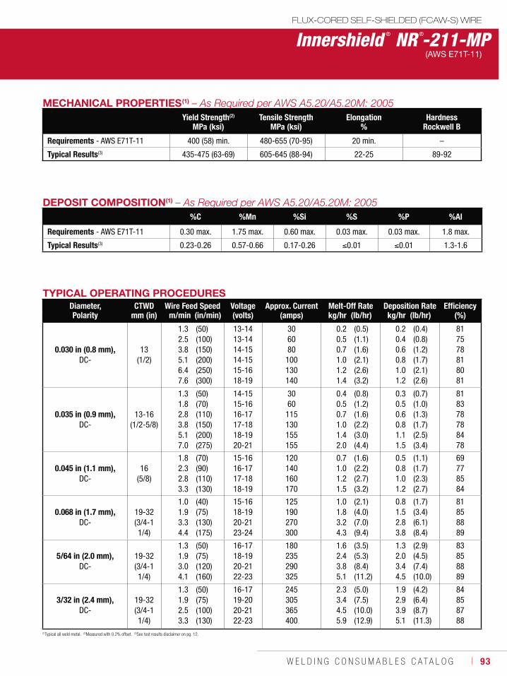
W E L D I N G C O N S U M A B L E S C A T A L O G ı 93
Innershield ® NR ®-211-MPFLUX-CORED SELF-SHIELDED (FCAW-S) WIRE
(AWS E71T-11)
DEPOSIT COMPOSITION(1)
%C %Mn %Si %S %P %Al
Requirements - AWS E71T-11 0.30 max. 1.75 max. 0.60 max. 0.03 max. 0.03 max. 1.8 max.
Typical Results(3) 0.23-0.26 0.57-0.66 0.17-0.26 0.01 0.01 1.3-1.6
(1)Typical all weld metal. (2)Measured with 0.2% offset. (3)See test results disclaimer on pg. 12.
TYPICAL OPERATING PROCEDURESDiameter, Polarity
CTWDmm (in)
Wire Feed Speed Voltage (volts)
Approx. Current(amps)
Melt-Off Rate Deposition Rate Efficiency(%)m/min (in/min) kg/hr (lb/hr) kg/hr (lb/hr)
0.030 in (0.8 mm),DC-
13 (1/2)
1.32.53.85.16.47.6
(50)(100)(150)(200)(250)(300)
13-1413-1414-1514-1515-1618-19
306080
100130140
0.20.50.71.01.21.4
(0.5)(1.1)(1.6)(2.1)(2.6)(3.2)
0.20.40.60.81.01.2
(0.4)(0.8)(1.2)(1.7)(2.1)(2.6)
817578818081
0.035 in (0.9 mm),DC-
13-16 (1/2-5/8)
1.31.82.83.85.17.0
(50)(70)(110)(150)(200)(275)
14-1515-1616-1717-1818-1920-21
3060
115130155155
0.40.50.71.01.42.0
(0.8)(1.2)(1.6)(2.2)(3.0)(4.4)
0.30.50.60.81.11.5
(0.7)(1.0)(1.3)(1.7)(2.5)(3.4)
818378788478
0.045 in (1.1 mm),DC-
16 (5/8)
1.82.32.83.3
(70)(90)(110)(130)
15-1616-1717-1818-19
120140160170
0.71.01.21.5
(1.6)(2.2)(2.7)(3.2)
0.50.81.01.2
(1.1)(1.7)(2.3)(2.7)
69778584
0.068 in (1.7 mm),DC-
19-32(3/4-1 1/4)
1.01.93.34.4
(40)(75)(130)(175)
15-1618-1920-2123-24
125190270300
1.01.83.24.3
(2.1)(4.0)(7.0)(9.4)
0.81.52.83.8
(1.7)(3.4)(6.1)(8.4)
81858889
5/64 in (2.0 mm),DC-
19-32 (3/4-1 1/4)
1.31.93.04.1
(50)(75)(120)(160)
16-1718-1920-2122-23
180235290325
1.62.43.85.1
(3.5)(5.3)(8.4)(11.2)
1.32.03.44.5
(2.9)(4.5)(7.4)(10.0)
83858889
3/32 in (2.4 mm),DC-
19-32 (3/4-1 1/4)
1.31.92.53.3
(50)(75)(100)(130)
16-1719-2020-2122-23
245305365400
2.33.44.55.9
(5.0)(7.5)(10.0)(12.9)
1.92.93.95.1
(4.2)(6.4)(8.7)(11.3)
84858788
MECHANICAL PROPERTIES(1)
Yield Strength(2)
MPa (ksi)Tensile Strength
MPa (ksi)Elongation
%Hardness
Rockwell B
Requirements - AWS E71T-11 400 (58) min. 480-655 (70-95) 20 min. –
Typical Results(3) 435-475 (63-69) 605-645 (88-94) 22-25 89-92
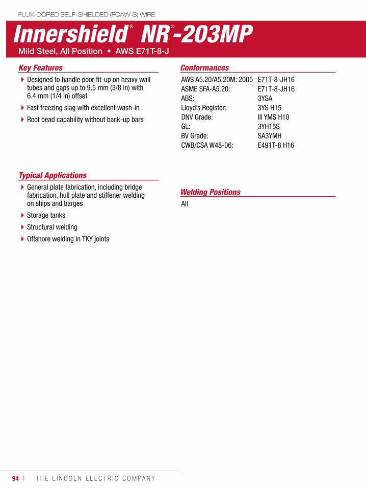
94 ı T H E L I N C O L N E L E C T R I C C O M P A N Y
Innershield ® NR ®-203MPFLUX-CORED SELF-SHIELDED (FCAW-S) WIRE
Welding Positions
Typical Applications
All
General plate fabrication, including bridge fabrication, hull plate and stiffener welding on ships and barges
Storage tanks
Structural welding
Offshore welding in TKY joints
Designed to handle poor fit-up on heavy wall tubes and gaps up to 9.5 mm (3/8 in) with 6.4 mm (1/4 in) offset
Fast freezing slag with excellent wash-in
Root bead capability without back-up bars
ConformancesKey FeaturesAWS A5.20/A5.20M: 2005ASME SFA-A5.20:ABS:Lloyd’s Register:DNV Grade:GL:BV Grade:CWB/CSA W48-06:
E71T-8-JH16E71T-8-JH163YSA3YS H15III YMS H103YH15SSA3YMHE491T-8 H16
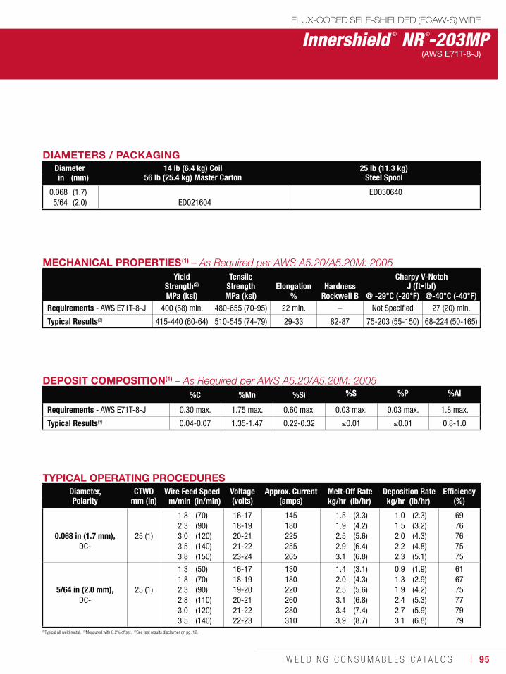
W E L D I N G C O N S U M A B L E S C A T A L O G ı 95
DIAMETERS / PACKAGINGDiameter 14 lb (6.4 kg) Coil
56 lb (25.4 kg) Master Carton25 lb (11.3 kg)
Steel Spoolin (mm)
0.0685/64
(1.7)(2.0) ED021604
ED030640
DEPOSIT COMPOSITION(1)
%C %Mn %Si %S %P %Al
Requirements - AWS E71T-8-J 0.30 max. 1.75 max. 0.60 max. 0.03 max. 0.03 max. 1.8 max.
Typical Results(3) 0.04-0.07 1.35-1.47 0.22-0.32 0.01 0.01 0.8-1.0
MECHANICAL PROPERTIES(1)
Yield Strength(2)
Tensile Strength Elongation Hardness
Charpy V-NotchJ (ft•lbf)
MPa (ksi) MPa (ksi) % Rockwell B @ -29°C (-20°F) @-40°C (-40°F)Requirements - AWS E71T-8-J 400 (58) min. 480-655 (70-95) 22 min. – Not Specified 27 (20) min.
Typical Results(3) 415-440 (60-64) 510-545 (74-79) 29-33 82-87 75-203 (55-150) 68-224 (50-165)
(1)Typical all weld metal. (2)Measured with 0.2% offset. (3)See test results disclaimer on pg. 12.
TYPICAL OPERATING PROCEDURESDiameter, Polarity
CTWDmm (in)
Wire Feed Speed Voltage (volts)
Approx. Current(amps)
Melt-Off Rate Deposition Rate Efficiency(%)m/min (in/min) kg/hr (lb/hr) kg/hr (lb/hr)
0.068 in (1.7 mm),DC-
25 (1)
1.82.33.03.53.8
(70)(90)(120)(140)(150)
16-1718-1920-2121-2223-24
145180225255265
1.51.92.52.93.1
(3.3)(4.2)(5.6)(6.4)(6.8)
1.01.52.02.22.3
(2.3)(3.2)(4.3)(4.8)(5.1)
6976767575
5/64 in (2.0 mm),DC-
25 (1)
1.31.82.32.83.03.5
(50)(70)(90)(110)(120)(140)
16-1718-1919-2020-2121-2222-23
130180220260280310
1.42.02.53.13.43.9
(3.1)(4.3)(5.6)(6.8)(7.4)(8.7)
0.91.31.92.42.73.1
(1.9)(2.9)(4.2)(5.3)(5.9)(6.8)
616775777979
FLUX-CORED SELF-SHIELDED (FCAW-S) WIRE
Innershield ® NR ®-203MP(AWS E71T-8-J)
96 ı T H E L I N C O L N E L E C T R I C C O M P A N Y
Innershield ® NR ®-232
Welding Positions
Typical Applications
All
Structural fabrication, including those subject to seismic requirements
General plate fabrication
Hull plate and stiffener welding on ships and barges
Machinery parts, tanks, hoppers, racks and scaffolding
High deposition rates for out-of-position welding
Penetrating arc
Fast freezing, easy to remove slag system
Meets AWS D1.8 seismic lot waiver requirements
ConformancesKey FeaturesAWS A5.20/A5.20M: 2005ASME SFA-A5.20:ABS: Lloyd’s Register:DNV Grade:GL:BV Grade:CWB/CSA W48-06: DB: TUV:MIL-E-24403/1:*FEMA 353AWS D1.8
E71T-8-H16E71T-8-H163YSA3YS H15III YMS H153YH10SSA3YMHE491T-8 H16EN 758 T42 3 Y N 2EN 758 T42 3 Y N 2MIL-71T-8AS
*Military Grade Classification of MIL-71T-8AS for 0.068 in (1.7 mm) and 0.072 in (1.8 mm) diameters only.
FLUX-CORED SELF-SHIELDED (FCAW-S) WIREStructural Welding Code Seismic Supplement
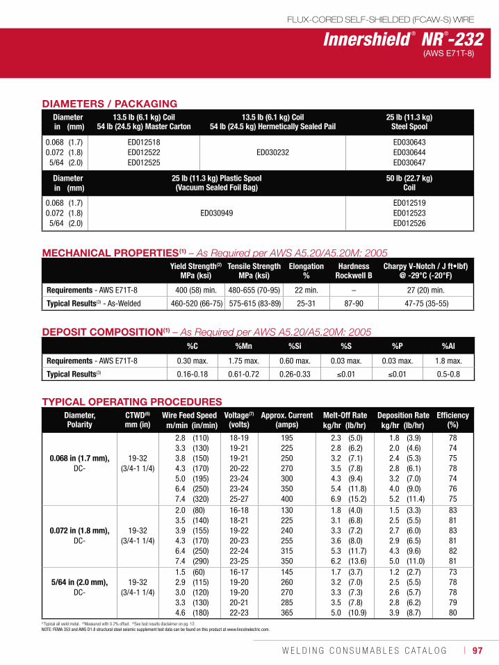
W E L D I N G C O N S U M A B L E S C A T A L O G ı 97
DIAMETERS / PACKAGINGDiameter 13.5 lb (6.1 kg) Coil
54 lb (24.5 kg) Master Carton13.5 lb (6.1 kg) Coil
54 lb (24.5 kg) Hermetically Sealed Pail25 lb (11.3 kg)
Steel Spoolin (mm)
0.0680.0725/64
(1.7)(1.8)(2.0)
ED012518ED012522ED012525
ED030232ED030643ED030644ED030647
Diameter 25 lb (11.3 kg) Plastic Spool (Vacuum Sealed Foil Bag)
50 lb (22.7 kg)Coilin (mm)
0.0680.0725/64
(1.7)(1.8)(2.0)
ED030949ED012519ED012523ED012526
DEPOSIT COMPOSITION(1)
%C %Mn %Si %S %P %Al
Requirements - AWS E71T-8 0.30 max. 1.75 max. 0.60 max. 0.03 max. 0.03 max. 1.8 max.
Typical Results(3) 0.16-0.18 0.61-0.72 0.26-0.33 0.01 0.01 0.5-0.8
MECHANICAL PROPERTIES(1)
Yield Strength(2)
MPa (ksi)Tensile Strength
MPa (ksi)Elongation
%Hardness
Rockwell BCharpy V-Notch / J ft•lbf)
@ -29°C (-20°F)
Requirements - AWS E71T-8 400 (58) min. 480-655 (70-95) 22 min. – 27 (20) min.
Typical Results(3) - As-Welded 460-520 (66-75) 575-615 (83-89) 25-31 87-90 47-75 (35-55)
(1)Typical all weld metal. (2)Measured with 0.2% offset. (3)See test results disclaimer on pg. 12. NOTE: FEMA 353 and AWS D1.8 structural steel seismic supplement test data can be found on this product at www.lincolnelectric.com.
TYPICAL OPERATING PROCEDURESDiameter, Polarity
CTWD(6)
mm (in)Wire Feed Speed Voltage(7)
(volts)Approx. Current
(amps)Melt-Off Rate Deposition Rate Efficiency
(%)m/min (in/min) kg/hr (lb/hr) kg/hr (lb/hr)
0.068 in (1.7 mm),DC-
19-32 (3/4-1 1/4)
2.83.33.84.35.06.47.4
(110)(130)(150)(170)(195)(250)(320)
18-1919-2119-2120-2223-2423-2425-27
195225250270300350400
2.32.83.23.54.35.46.9
(5.0)(6.2)(7.1)(7.8)(9.4)(11.8)(15.2)
1.82.02.42.83.24.05.2
(3.9)(4.6)(5.3)(6.1)(7.0)(9.0)(11.4)
78747578747675
0.072 in (1.8 mm),DC-
19-32 (3/4-1 1/4)
2.03.53.94.36.47.4
(80)(140)(155)(170)(250)(290)
16-1818-2119-2220-2322-2423-25
130225240255315350
1.83.13.33.65.36.2
(4.0)(6.8)(7.2)(8.0)(11.7)(13.6)
1.52.52.72.94.35.0
(3.3)(5.5)(6.0)(6.5)(9.6)(11.0)
838183818281
5/64 in (2.0 mm),DC-
19-32 (3/4-1 1/4)
1.52.93.03.34.6
(60)(115)(120)(130)(180)
16-1719-2019-2020-2122-23
145260270285365
1.73.23.33.55.0
(3.7)(7.0)(7.3)(7.8)(10.9)
1.22.52.62.83.9
(2.7)(5.5)(5.7)(6.2)(8.7)
7378787980
FLUX-CORED SELF-SHIELDED (FCAW-S) WIRE
Innershield ® NR ®-232(AWS E71T-8)
98 ı T H E L I N C O L N E L E C T R I C C O M P A N Y
Innershield ® NR ®-233
Welding Positions
Typical ApplicationsAll
Structural fabrication, including those subject to seismic requirements
General plate fabrication
Ship and barge fabrication
Vertical up and overhead fillets and groove welds
High deposition rates for out-of-position welding
Welder-friendly, easy to use and great bead appearance
Minimal gas marking
Meets AWS D1.8 seismic lot waiver requirements
ConformancesKey FeaturesAWS A5.20/A5.20M: 2005ASME SFA-A5.20:ABS: EN ISO 17632-B:FEMA 353AWS D1.8
E71T-8-H16E71T-8-H16E71T-8-H16T493T8-1NA-H15
NotesInnershield® K126 Gun Assembly requires one of the following gun tube assemblies for better wire feeding - KP2454-1 (62°, 7.5 in), KP2455-1 (45°, 6 in), KP2456-1 (30°, 12 in)
FLUX-CORED SELF-SHIELDED (FCAW-S) WIREStructural Welding Code Seismic Supplement
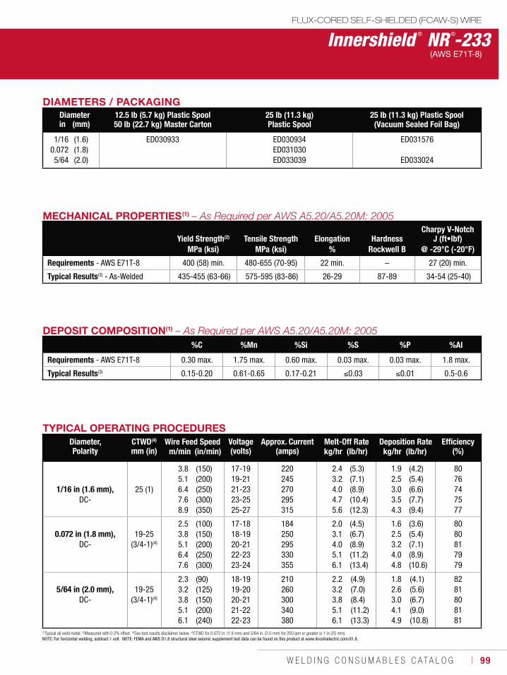
W E L D I N G C O N S U M A B L E S C A T A L O G ı 99
DIAMETERS / PACKAGINGDiameter 12.5 lb (5.7 kg) Plastic Spool
50 lb (22.7 kg) Master Carton25 lb (11.3 kg)Plastic Spool
25 lb (11.3 kg) Plastic Spool (Vacuum Sealed Foil Bag)in (mm)
1/160.0725/64
(1.6)(1.8)(2.0)
ED030933 ED030934ED031030ED033039
ED031576
ED033024
Innershield ® NR ®-233(AWS E71T-8)
DEPOSIT COMPOSITION(1)
%C %Mn %Si %S %P %Al
Requirements - AWS E71T-8 0.30 max. 1.75 max. 0.60 max. 0.03 max. 0.03 max. 1.8 max.
Typical Results(3) 0.15-0.20 0.61-0.65 0.17-0.21 0.03 0.01 0.5-0.6
(1)Typical all weld metal. (2)Measured with 0.2% offset. (3)See test results disclaimer below. (4)CTWD for 0.072 in. (1.8 mm) and 5/64 in. (2.0 mm) for 200 ipm or greater is 1 in (25 mm).NOTE: For horizontal welding, subtract 1 volt. NOTE: FEMA and AWS D1.8 structural steel seismic supplement test data can be found on this product at www.lincolnelectric.com/d1.8.
TYPICAL OPERATING PROCEDURESDiameter, Polarity
CTWD(4)
mm (in)Wire Feed Speed Voltage
(volts)Approx. Current
(amps)Melt-Off Rate Deposition Rate Efficiency
(%)m/min (in/min) kg/hr (lb/hr) kg/hr (lb/hr)
1/16 in (1.6 mm),DC-
25 (1)
3.85.16.47.68.9
(150)(200)(250)(300)(350)
17-1919-2121-2323-2525-27
220245270295315
2.43.24.04.75.6
(5.3)(7.1)(8.9)(10.4)(12.3)
1.92.53.03.54.3
(4.2)(5.4)(6.6)(7.7)(9.4)
8076747577
0.072 in (1.8 mm),DC-
19-25(3/4-1)(4)
2.53.85.16.47.6
(100)(150)(200)(250)(300)
17-1818-1920-2122-2323-24
184250295330355
2.03.14.05.16.1
(4.5)(6.7)(8.9)(11.2)(13.4)
1.62.53.24.04.8
(3.6)(5.4)(7.1)(8.9)(10.6)
8080817979
5/64 in (2.0 mm),DC-
19-25 (3/4-1)(4)
2.33.23.85.16.1
(90)(125)(150)(200)(240)
18-1919-2020-2121-2222-23
210260300340380
2.23.23.85.16.1
(4.9)(7.0)(8.4)(11.2)(13.3)
1.82.63.04.14.9
(4.1)(5.6)(6.7)(9.0)(10.8)
8281808181
MECHANICAL PROPERTIES(1)
Yield Strength(2) Tensile Strength Elongation HardnessCharpy V-Notch
J (ft•lbf)MPa (ksi) MPa (ksi) % Rockwell B @ -29°C (-20°F)
Requirements - AWS E71T-8 400 (58) min. 480-655 (70-95) 22 min. – 27 (20) min.
Typical Results(3) - As-Welded 435-455 (63-66) 575-595 (83-86) 26-29 87-89 34-54 (25-40)
FLUX-CORED SELF-SHIELDED (FCAW-S) WIRE
100 ı T H E L I N C O L N E L E C T R I C C O M P A N Y
Innershield ® NR ®-311 Ni
Welding PositionsTypical Applications
Flat & HorizontalFillet and lap welds
Horizontal and square edge butt welds, such as column-to-column structural connections
Deep groove welds
Structural fabrication
Weathering steels
Designed to provide a nominal 1.5% nickel weld deposit
High deposition rates and fast travel speeds
Capable of producing weld deposits with impact properties exceeding 27 J (20 ft•lbf) at -29°C (-20°F)
Color match on weathering steel applications
3/32 in (2.4 mm) diameter meets FEMA 353 and AWS D1.8 seismic lot waiver requirements
ConformancesKey FeaturesAWS A5.29/A5.29M: 2005ASME SFA-A5.29:ABS:Lloyd’s Register:DNV Grade:GL:BV Grade:DB:FEMA 353:AWS D1.8:
E70T7-K2-H16, E80TG-K2E70T7-K2-H16, E80TG-K22YSA2YSII YMS2YSSA2YMEN 758 T42 2 1, 5Ni W N 53/32 in (2.4 mm) only3/32 in (2.4 mm) only
FLUX-CORED SELF-SHIELDED (FCAW-S) WIREStructural Welding Code Seismic Supplement
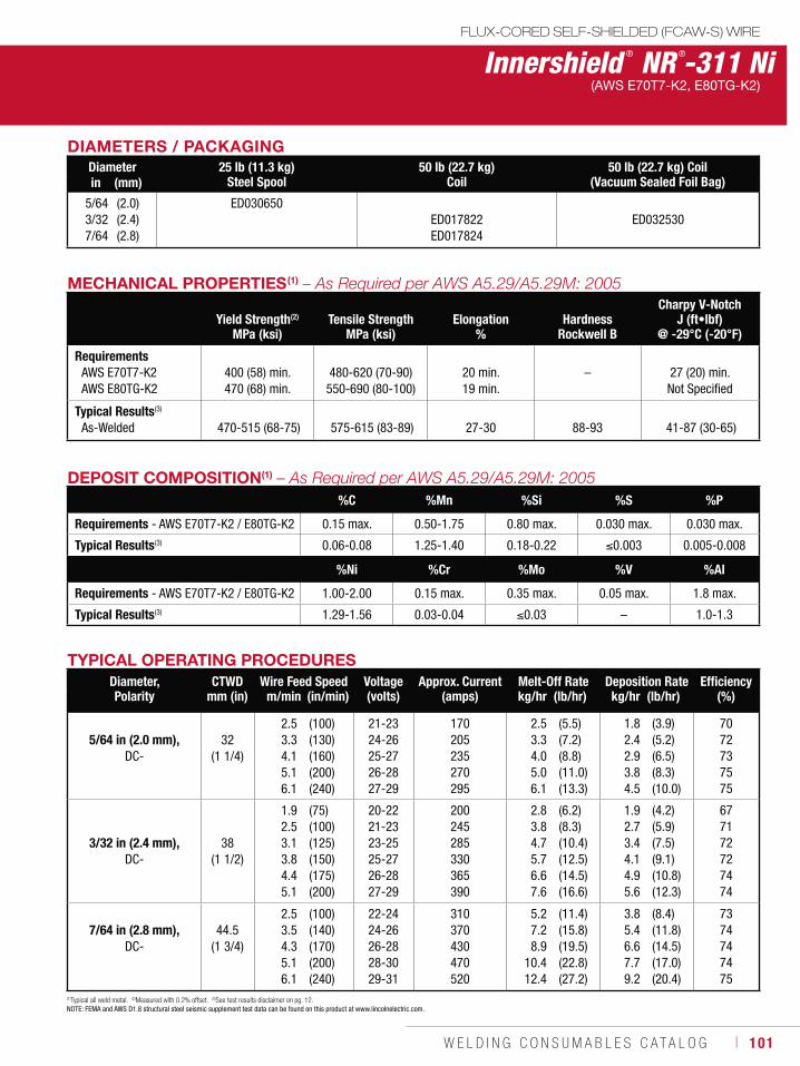
W E L D I N G C O N S U M A B L E S C A T A L O G ı 101
Innershield ® NR ®-311 Ni(AWS E70T7-K2, E80TG-K2)
DEPOSIT COMPOSITION(1)
%C %Mn %Si %S %P
Requirements - AWS E70T7-K2 / E80TG-K2 0.15 max. 0.50-1.75 0.80 max. 0.030 max. 0.030 max.
Typical Results(3) 0.06-0.08 1.25-1.40 0.18-0.22 0.003 0.005-0.008
%Ni %Cr %Mo %V %Al
Requirements - AWS E70T7-K2 / E80TG-K2 1.00-2.00 0.15 max. 0.35 max. 0.05 max. 1.8 max.
Typical Results(3) 1.29-1.56 0.03-0.04 0.03 – 1.0-1.3
(1)Typical all weld metal. (2)Measured with 0.2% offset. (3)See test results disclaimer on pg. 12.NOTE: FEMA and AWS D1.8 structural steel seismic supplement test data can be found on this product at www.lincolnelectric.com.
TYPICAL OPERATING PROCEDURESDiameter, Polarity
CTWDmm (in)
Wire Feed Speed Voltage (volts)
Approx. Current(amps)
Melt-Off Rate Deposition Rate Efficiency(%)m/min (in/min) kg/hr (lb/hr) kg/hr (lb/hr)
5/64 in (2.0 mm),DC-
32 (1 1/4)
2.53.34.15.16.1
(100)(130)(160)(200)(240)
21-2324-2625-2726-2827-29
170205235270295
2.53.34.05.06.1
(5.5)(7.2)(8.8)(11.0)(13.3)
1.82.42.93.84.5
(3.9)(5.2)(6.5)(8.3)(10.0)
7072737575
3/32 in (2.4 mm),DC-
38 (1 1/2)
1.92.53.13.84.45.1
(75)(100)(125)(150)(175)(200)
20-2221-2323-2525-2726-2827-29
200245285330365390
2.83.84.75.76.67.6
(6.2)(8.3)(10.4)(12.5)(14.5)(16.6)
1.92.73.44.14.95.6
(4.2)(5.9)(7.5)(9.1)(10.8)(12.3)
677172727474
7/64 in (2.8 mm),DC-
44.5 (1 3/4)
2.53.54.35.16.1
(100)(140)(170)(200)(240)
22-2424-2626-2828-3029-31
310370430470520
5.27.28.9
10.412.4
(11.4)(15.8)(19.5)(22.8)(27.2)
3.85.46.67.79.2
(8.4)(11.8)(14.5)(17.0)(20.4)
7374747475
MECHANICAL PROPERTIES(1)
Yield Strength(2)
MPa (ksi)Tensile Strength
MPa (ksi)Elongation
%Hardness
Rockwell B
Charpy V-NotchJ (ft•lbf)
@ -29°C (-20°F)
RequirementsAWS E70T7-K2AWS E80TG-K2
400 (58) min.470 (68) min.
480-620 (70-90)550-690 (80-100)
20 min.19 min.
– 27 (20) min.Not Specified
Typical Results(3)
As-Welded 470-515 (68-75) 575-615 (83-89) 27-30 88-93 41-87 (30-65)
FLUX-CORED SELF-SHIELDED (FCAW-S) WIRE
DIAMETERS / PACKAGINGDiameter 25 lb (11.3 kg)
Steel Spool50 lb (22.7 kg)
Coil50 lb (22.7 kg) Coil
(Vacuum Sealed Foil Bag)in (mm)
5/643/327/64
(2.0)(2.4)(2.8)
ED030650ED017822ED017824
ED032530
102 ı T H E L I N C O L N E L E C T R I C C O M P A N Y
Structural Welding Code Seismic Supplement
Innershield ® NR ®-FAB-70
Welding Positions
Notes
Typical Applications
Flat & Horizontal
Welding at high heat input procedures and slow travel speeds will significantly reduce the risk of slag entrapment.
Structural fabrication
Proprietary design increases wire stiffness to aid feedability and promotes a smooth arc transfer.
Capable of producing weld deposits with impact properties exceeding an average of 54 J (40 ft•lbf) at -29°C (-20°F).
Meets FEMA 353 and AWS D1.8 seismic lot waiver requirements
ConformancesKey FeaturesAWS A5.29/A5.29M: 2005ASME SFA-5.29 FEMA 353AWS D1.8
E70T7-GE70T7-G
FLUX-CORED SELF-SHIELDED (FCAW-S) WIRE
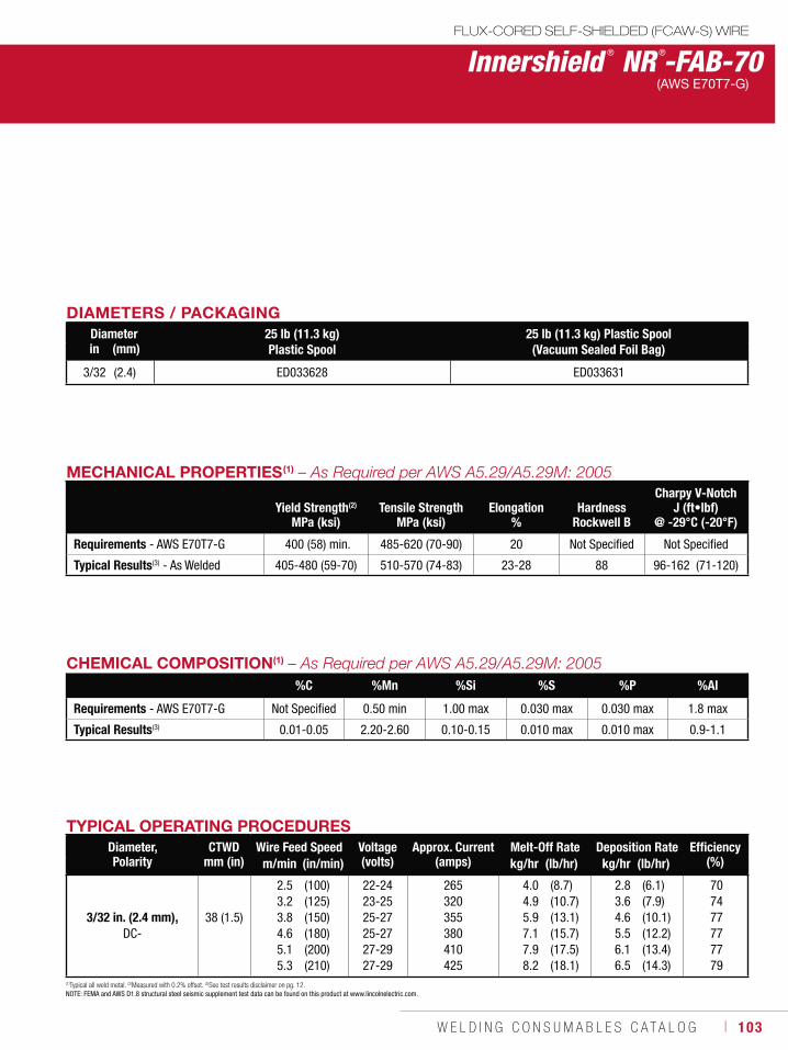
W E L D I N G C O N S U M A B L E S C A T A L O G ı 103
DIAMETERS / PACKAGINGDiameter 25 lb (11.3 kg)
Plastic Spool25 lb (11.3 kg) Plastic Spool (Vacuum Sealed Foil Bag)in (mm)
3/32 (2.4) ED033628 ED033631
MECHANICAL PROPERTIES(1)
Yield Strength(2)
MPa (ksi)Tensile Strength
MPa (ksi)Elongation
%Hardness
Rockwell B
Charpy V-NotchJ (ft•lbf)
@ -29°C (-20°F)
Requirements - AWS E70T7-G 400 (58) min. 485-620 (70-90) 20 Not Specified Not Specified
Typical Results(3) - As Welded 405-480 (59-70) 510-570 (74-83) 23-28 88 96-162 (71-120)
(1)Typical all weld metal. (2)Measured with 0.2% offset. (3)See test results disclaimer on pg. 12. NOTE: FEMA and AWS D1.8 structural steel seismic supplement test data can be found on this product at www.lincolnelectric.com.
CHEMICAL COMPOSITION(1)
%C %Mn %Si %S %P %Al
Requirements - AWS E70T7-G Not Specified 0.50 min 1.00 max 0.030 max 0.030 max 1.8 max
Typical Results(3) 0.01-0.05 2.20-2.60 0.10-0.15 0.010 max 0.010 max 0.9-1.1
TYPICAL OPERATING PROCEDURESDiameter, Polarity
CTWDmm (in)
Wire Feed Speed Voltage (volts)
Approx. Current(amps)
Melt-Off Rate Deposition Rate Efficiency(%)m/min (in/min) kg/hr (lb/hr) kg/hr (lb/hr)
3/32 in. (2.4 mm),DC-
38 (1.5)
2.53.23.84.65.15.3
(100)(125)(150)(180)(200)(210)
22-2423-2525-2725-2727-2927-29
265320355380410425
4.04.95.97.17.98.2
(8.7)(10.7)(13.1)(15.7)(17.5)(18.1)
2.83.64.65.56.16.5
(6.1)(7.9)(10.1)(12.2)(13.4)(14.3)
707477777779
FLUX-CORED SELF-SHIELDED (FCAW-S) WIRE
Innershield ® NR ®-FAB-70(AWS E70T7-G)
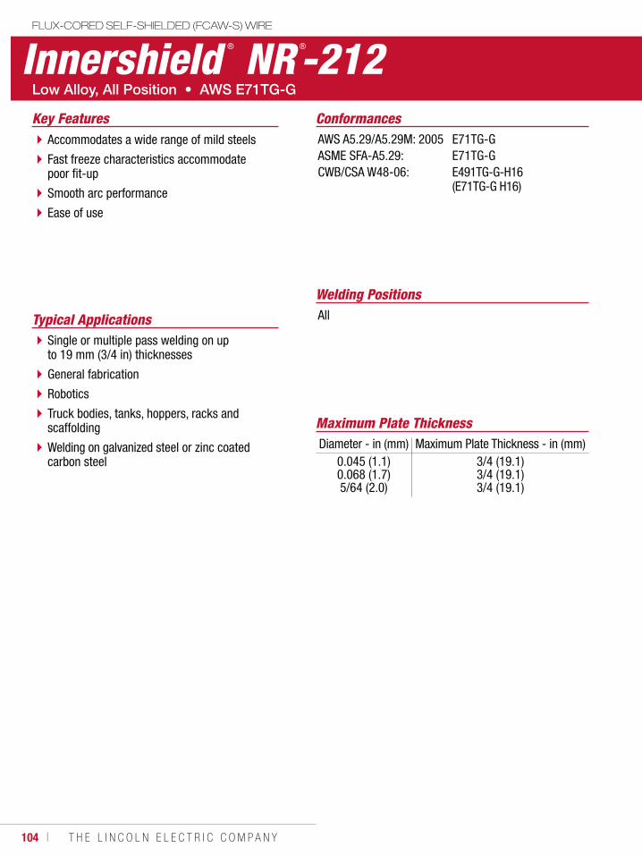
104 ı T H E L I N C O L N E L E C T R I C C O M P A N Y
Innershield ® NR ®-212FLUX-CORED SELF-SHIELDED (FCAW-S) WIRE
Welding Positions
Typical Applications All
Single or multiple pass welding on up to 19 mm (3/4 in) thicknesses
General fabrication
Robotics
Truck bodies, tanks, hoppers, racks and scaffolding
Welding on galvanized steel or zinc coated carbon steel
Accommodates a wide range of mild steels
Fast freeze characteristics accommodate poor fit-up
Smooth arc performance
Ease of use
ConformancesKey FeaturesAWS A5.29/A5.29M: 2005ASME SFA-A5.29:CWB/CSA W48-06:
E71TG-GE71TG-GE491TG-G-H16 (E71TG-G H16)
Maximum Plate ThicknessDiameter - in (mm) Maximum Plate Thickness - in (mm)
0.045 (1.1)0.068 (1.7)5/64 (2.0)
3/4 (19.1)3/4 (19.1)3/4 (19.1)
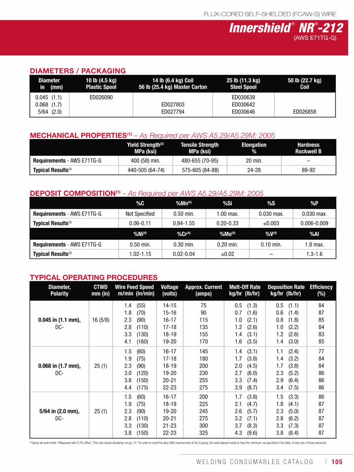
W E L D I N G C O N S U M A B L E S C A T A L O G ı 105
MECHANICAL PROPERTIES(1)
Yield Strength(2)
MPa (ksi)Tensile Strength
MPa (ksi)Elongation
%Hardness
Rockwell B
Requirements - AWS E71TG-G 400 (58) min. 480-655 (70-95) 20 min. –
Typical Results(3) 440-505 (64-74) 575-605 (84-88) 24-28 89-92
Innershield ® NR ®-212FLUX-CORED SELF-SHIELDED (FCAW-S) WIRE
(AWS E71TG-G)
(1)Typical all weld metal. (2)Measured with 0.2% offset. (3)See test results disclaimer on pg. 12. (4)In order to meet the alloy AWS requirements of the G group, the weld deposit needs to have the minimum, as specified in the table, of only one of these elements.
DEPOSIT COMPOSITION(1)
%C %Mn(4) %Si %S %P
Requirements - AWS E71TG-G Not Specified 0.50 min. 1.00 max. 0.030 max. 0.030 max.
Typical Results(3) 0.06-0.11 0.84-1.55 0.20-0.33 0.003 0.006-0.009
%Ni(4) %Cr(4) %Mo(4) %V(4) %Al
Requirements - AWS E71TG-G 0.50 min. 0.30 min. 0.20 min. 0.10 min. 1.8 max.
Typical Results(3) 1.02-1.15 0.02-0.04 0.02 – 1.3-1.6
TYPICAL OPERATING PROCEDURESDiameter, Polarity
CTWDmm (in)
Wire Feed Speed Voltage (volts)
Approx. Current(amps)
Melt-Off Rate Deposition Rate Efficiency(%)m/min (in/min) kg/hr (lb/hr) kg/hr (lb/hr)
0.045 in (1.1 mm),DC-
16 (5/8)
1.41.82.32.83.34.1
(55)(70)(90)(110)(130)(160)
14-1515-1616-1717-1818-1919-20
7590
115135155170
0.50.71.01.21.41.6
(1.3)(1.6)(2.1)(2.6)(3.1)(3.5)
0.50.60.81.01.21.4
(1.1)(1.4)(1.8)(2.2)(2.6)(3.0)
848785848385
0.068 in (1.7 mm),DC-
25 (1)
1.51.92.33.03.84.4
(60)(75)(90)(120)(150)(175)
16-1717-1818-1919-2020-2122-23
145180200230255275
1.41.72.02.73.33.9
(3.1)(3.8)(4.5)(6.0)(7.4)(8.7)
1.11.41.72.32.93.4
(2.4)(3.2)(3.8)(5.2)(6.4)(7.5)
778484868686
5/64 in (2.0 mm),DC-
25 (1)
1.51.92.32.83.33.8
(60)(75)(90)(110)(130)(150)
16-1718-1919-2020-2121-2322-23
200225245275300325
1.72.12.63.23.74.3
(3.8)(4.7)(5.7)(7.1)(8.3)(9.6)
1.51.82.32.83.33.8
(3.3)(4.1)(5.0)(6.2)(7.3)(8.4)
868787878787
DIAMETERS / PACKAGINGDiameter 10 lb (4.5 kg)
Plastic Spool14 lb (6.4 kg) Coil
56 lb (25.4 kg) Master Carton25 lb (11.3 kg)
Steel Spool50 lb (22.7 kg)
Coilin (mm)
0.0450.0685/64
(1.1)(1.7)(2.0)
ED026090ED027803ED027794
ED030639ED030642ED030646 ED026858
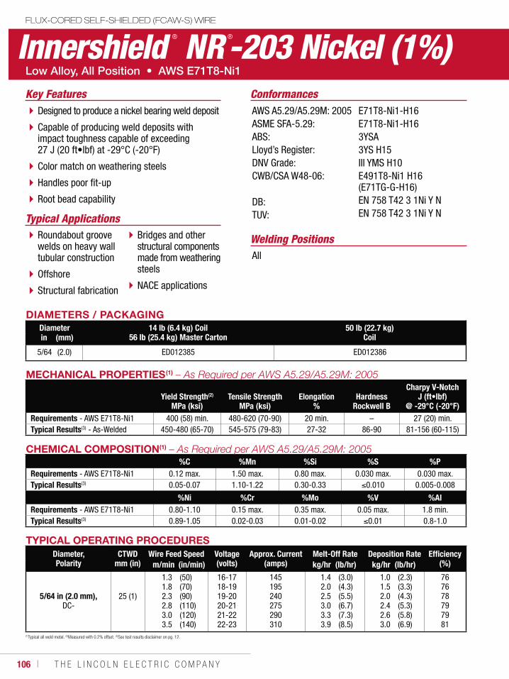
106 ı T H E L I N C O L N E L E C T R I C C O M P A N Y
Innershield ® NR ®-203 Nickel (1%)
Welding Positions
Typical Applications
All
Roundabout groove welds on heavy wall tubular construction
Offshore
Structural fabrication
Bridges and other structural components made from weathering steels
NACE applications
Designed to produce a nickel bearing weld deposit
Capable of producing weld deposits with impact toughness capable of exceeding 27 J (20 ft•lbf) at -29°C (-20°F)
Color match on weathering steels
Handles poor fit-up
Root bead capability
ConformancesKey FeaturesAWS A5.29/A5.29M: 2005ASME SFA-5.29:ABS:Lloyd’s Register:DNV Grade:CWB/CSA W48-06:
DB:TUV:
E71T8-Ni1-H16E71T8-Ni1-H163YSA3YS H15III YMS H10E491T8-Ni1 H16 (E71TG-G-H16)EN 758 T42 3 1Ni Y NEN 758 T42 3 1Ni Y N
DIAMETERS / PACKAGINGDiameter 14 lb (6.4 kg) Coil
56 lb (25.4 kg) Master Carton50 lb (22.7 kg)
Coilin (mm)
5/64 (2.0) ED012385 ED012386
FLUX-CORED SELF-SHIELDED (FCAW-S) WIRE
MECHANICAL PROPERTIES(1)
Yield Strength(2)
MPa (ksi)Tensile Strength
MPa (ksi)Elongation
%Hardness
Rockwell B
Charpy V-NotchJ (ft•lbf)
@ -29°C (-20°F)Requirements - AWS E71T8-Ni1 400 (58) min. 480-620 (70-90) 20 min. – 27 (20) min.Typical Results(3) - As-Welded 450-480 (65-70) 545-575 (79-83) 27-32 86-90 81-156 (60-115)
(1)Typical all weld metal. (2)Measured with 0.2% offset. (3)See test results disclaimer on pg. 12.
CHEMICAL COMPOSITION(1)
%C %Mn %Si %S %PRequirements - AWS E71T8-Ni1 0.12 max. 1.50 max. 0.80 max. 0.030 max. 0.030 max.Typical Results(3) 0.05-0.07 1.10-1.22 0.30-0.33 0.010 0.005-0.008
%Ni %Cr %Mo %V %AlRequirements - AWS E71T8-Ni1 0.80-1.10 0.15 max. 0.35 max. 0.05 max. 1.8 min.Typical Results(3) 0.89-1.05 0.02-0.03 0.01-0.02 0.01 0.8-1.0
TYPICAL OPERATING PROCEDURESDiameter, Polarity
CTWDmm (in)
Wire Feed Speed Voltage (volts)
Approx. Current(amps)
Melt-Off Rate Deposition Rate Efficiency(%)m/min (in/min) kg/hr (lb/hr) kg/hr (lb/hr)
5/64 in (2.0 mm),DC-
25 (1)
1.31.82.32.83.03.5
(50)(70)(90)(110)(120)(140)
16-1718-1919-2020-2121-2222-23
145195240275290310
1.42.02.53.03.33.9
(3.0)(4.3)(5.5)(6.7)(7.3)(8.5)
1.01.52.02.42.63.0
(2.3)(3.3)(4.3)(5.3)(5.8)(6.9)
767678797981
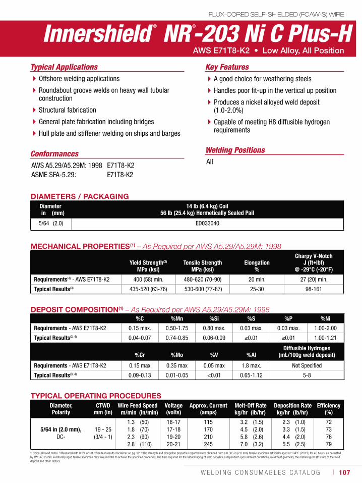
W E L D I N G C O N S U M A B L E S C A T A L O G ı 107
MECHANICAL PROPERTIES(1)
Yield Strength(2)
MPa (ksi)Tensile Strength
MPa (ksi)Elongation
%
Charpy V-NotchJ (ft•lbf)
@ -29°C (-20°F)
Requirements(4) - AWS E71T8-K2 400 (58) min. 480-620 (70-90) 20 min. 27 (20) min.
Typical Results(3) 435-520 (63-76) 530-600 (77-87) 25-30 98-161
DEPOSIT COMPOSITION(1)
%C %Mn %Si %S %P %Ni
Requirements - AWS E71T8-K2 0.15 max. 0.50-1.75 0.80 max. 0.03 max. 0.03 max. 1.00-2.00
Typical Results(3, 4) 0.04-0.07 0.74-0.85 0.06-0.09 0.01 0.01 1.00-1.21
%Cr %Mo %V %AlDiffusible Hydrogen
(mL/100g weld deposit)
Requirements - AWS E71T8-K2 0.15 max 0.35 max 0.05 max 1.8 max. Not Specified
Typical Results(3, 4) 0.09-0.13 0.01-0.05 <0.01 0.65-1.12 5-8
(1)Typical all weld metal. (2)Measured with 0.2% offset. (3)See test results disclaimer on pg. 12. (4)The strength and elongation properties reported were obtained from a 0.505 in (2.8 mm) tensile specimen artificially aged at 104°C (220°F) for 48 hours, as permitted by AWS A5.29-98. A naturally aged tensile specimen may take months to achieve the specified properties. The time required for the natural aging of weld deposits is dependent upon ambient conditions, weldment geometry, the metallurgical structure of the weld deposit and other factors.
TYPICAL OPERATING PROCEDURESDiameter, Polarity
CTWDmm (in)
Wire Feed Speed Voltage (volts)
Approx. Current(amps)
Melt-Off Rate Deposition Rate Efficiency(%)m/min (in/min) kg/hr (lb/hr) kg/hr (lb/hr)
5/64 in (2.0 mm),DC-
19 - 25(3/4 - 1)
1.31.82.32.8
(50)(70)(90)(110)
16-1717-1819-2020-21
115170210245
3.24.55.87.0
(1.5)(2.0)(2.6)(3.2)
2.33.34.45.5
(1.0)(1.5)(2.0)(2.5)
72737679
Innershield ® NR ®-203 Ni C Plus-HFLUX-CORED SELF-SHIELDED (FCAW-S) WIRE
Welding Positions
Typical Applications
All
Offshore welding applications
Roundabout groove welds on heavy wall tubular construction
Structural fabrication
General plate fabrication including bridges
Hull plate and stiffener welding on ships and barges
A good choice for weathering steels
Handles poor fit-up in the vertical up position
Produces a nickel alloyed weld deposit (1.0-2.0%)
Capable of meeting H8 diffusible hydrogen requirements
Conformances
Key Features
AWS A5.29/A5.29M: 1998ASME SFA-5.29:
E71T8-K2E71T8-K2
DIAMETERS / PACKAGINGDiameter 14 lb (6.4 kg) Coil
56 lb (25.4 kg) Hermetically Sealed Pailin (mm)
5/64 (2.0) ED033040
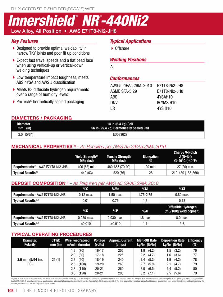
108 ı T H E L I N C O L N E L E C T R I C C O M P A N Y
MECHANICAL PROPERTIES(1)
Yield Strength(2)
MPa (ksi)Tensile Strength
MPa (ksi)Elongation
%
Charpy V-NotchJ (ft•lbf)
@-40°C (-40°F)
Requirements(4) - AWS E71T8-Ni2-JH8 400 (58) min. 480-655 (70-90) 20 min. 27 (20) min.
Typical Results(3) 440 (63) 520 (76) 28 210-480 (158-360)
DEPOSIT COMPOSITION(1)
%C %Mn %Ni %Si
Requirements - AWS E71T8-Ni2-JH8 0.12 max. 1.50 max. 1.75-2.75 0.80 max.
Typical Results(3,4) 0.01 0.76 1.8 0.13
%S %P %Al
Diffusible Hydrogen (mL/100g weld deposit)
Requirements - AWS E71T8-Ni2-JH8 0.030 max. 0.030 max. 1.8 max. 8.0 max.
Typical Results(3,4) 0.010 0.010 1.1 5-8
(1)Typical all weld metal. (2)Measured with 0.2% offset. (3)See test results disclaimer on pg. 12. (4)The strength and elongation properties reported were obtained from a 2.8 mm (0.505 in) tensile specimen artificially aged at 104°C (220°F) for 48 hours, as permitted by AWS A5.20-05. A naturally aged tensile specimen may take months to achieve the specified properties. See AWS A5.20-05, paragraph A8.3. The time required for the natural aging of weld deposits is dependent upon ambient conditions, weldment geometry, the metallurgical structure of the weld deposit and other factors.
TYPICAL OPERATING PROCEDURESDiameter, Polarity
CTWDmm (in)
Wire Feed Speed Voltage (volts)
Approx. Current(amps)
Melt-Off Rate Deposition Rate Efficiency(%)m/min (in/min) kg/hr (lb/hr) kg/hr (lb/hr)
2.0 mm (5/64 in),DC-
25 (1)
1.82.02.32.52.83.0
(70)(80)(90)(100)(110)(120)
16-1717-1818-1919-2020-2120-21
205225240260260295
1.92.22.42.73.03.2
(4.2)(4.7)(5.3)(5.9)(6.5)(7.1)
1.51.61.92.12.42.5
(3.2)(3.6)(4.2)(4.7)(5.2)(5.6)
767778798079
Innershield ® NR ®-440Ni2FLUX-CORED SELF-SHIELDED (FCAW-S) WIRE
Welding Positions
Typical Applications
All
OffshoreDesigned to provide optimal weldability in narrow TKY joints and poor fit up conditions
Expect fast travel speeds and a flat bead face when using vertical-up or vertical-down welding techniques
Low temperature impact toughness, meets ABS 4YSA and AWS J classification
Meets H8 diffusible hydrogen requirements over a range of humidity levels
ProTech® hermetically sealed packaging
Conformances
Key Features
AWS 5.29/A5.29M: 2010ASME SFA-5.29ABSDNVLR
E71T8-Ni2-JH8E71T8-Ni2-JH84YSAH10IV YMS H104YS H10
DIAMETERS / PACKAGINGDiameter 14 lb (6.4 kg) Coil
56 lb (25.4 kg) Hermetically Sealed Pailmm (in)
2.0 (5/64) ED033627
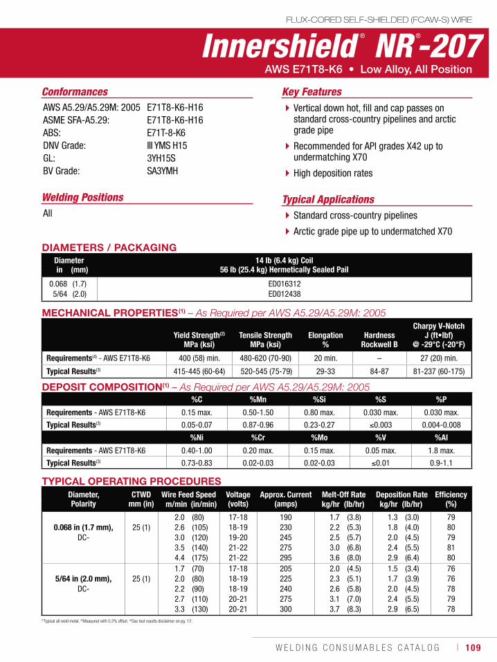
W E L D I N G C O N S U M A B L E S C A T A L O G ı 109
MECHANICAL PROPERTIES(1)
Yield Strength(2)
MPa (ksi)Tensile Strength
MPa (ksi)Elongation
%Hardness
Rockwell B
Charpy V-NotchJ (ft•lbf)
@ -29°C (-20°F)
Requirements(4) - AWS E71T8-K6 400 (58) min. 480-620 (70-90) 20 min. – 27 (20) min.
Typical Results(3) 415-445 (60-64) 520-545 (75-79) 29-33 84-87 81-237 (60-175)
DEPOSIT COMPOSITION(1)
%C %Mn %Si %S %P
Requirements - AWS E71T8-K6 0.15 max. 0.50-1.50 0.80 max. 0.030 max. 0.030 max.
Typical Results(3) 0.05-0.07 0.87-0.96 0.23-0.27 0.003 0.004-0.008
%Ni %Cr %Mo %V %Al
Requirements - AWS E71T8-K6 0.40-1.00 0.20 max. 0.15 max. 0.05 max. 1.8 max.
Typical Results(3) 0.73-0.83 0.02-0.03 0.02-0.03 0.01 0.9-1.1
(1)Typical all weld metal. (2)Measured with 0.2% offset. (3)See test results disclaimer on pg. 12.
TYPICAL OPERATING PROCEDURESDiameter, Polarity
CTWDmm (in)
Wire Feed Speed Voltage (volts)
Approx. Current(amps)
Melt-Off Rate Deposition Rate Efficiency(%)m/min (in/min) kg/hr (lb/hr) kg/hr (lb/hr)
0.068 in (1.7 mm),DC-
25 (1)2.02.63.03.54.4
(80)(105)(120)(140)(175)
17-1818-1919-2021-2221-22
190230245275295
1.72.22.53.03.6
(3.8)(5.3)(5.7)(6.8)(8.0)
1.31.82.02.42.9
(3.0)(4.0)(4.5)(5.5)(6.4)
7980798180
5/64 in (2.0 mm),DC-
25 (1)1.72.02.22.73.3
(70)(80)(90)(110)(130)
17-1818-1918-1920-2120-21
205225240275300
2.02.32.63.13.7
(4.5)(5.1)(5.8)(7.0)(8.3)
1.51.72.02.42.9
(3.4)(3.9)(4.5)(5.5)(6.5)
7676787978
Innershield ® NR ®-207FLUX-CORED SELF-SHIELDED (FCAW-S) WIRE
Welding Positions Typical ApplicationsAll Standard cross-country pipelines
Arctic grade pipe up to undermatched X70
Vertical down hot, fill and cap passes on standard cross-country pipelines and arctic grade pipe
Recommended for API grades X42 up to undermatching X70
High deposition rates
Conformances Key FeaturesAWS A5.29/A5.29M: 2005ASME SFA-A5.29:ABS:DNV Grade:GL:BV Grade:
E71T8-K6-H16E71T8-K6-H16E71T-8-K6III YMS H15 3YH15S SA3YMH
DIAMETERS / PACKAGINGDiameter 14 lb (6.4 kg) Coil
56 lb (25.4 kg) Hermetically Sealed Pailin (mm)
0.0685/64
(1.7)(2.0)
ED016312ED012438
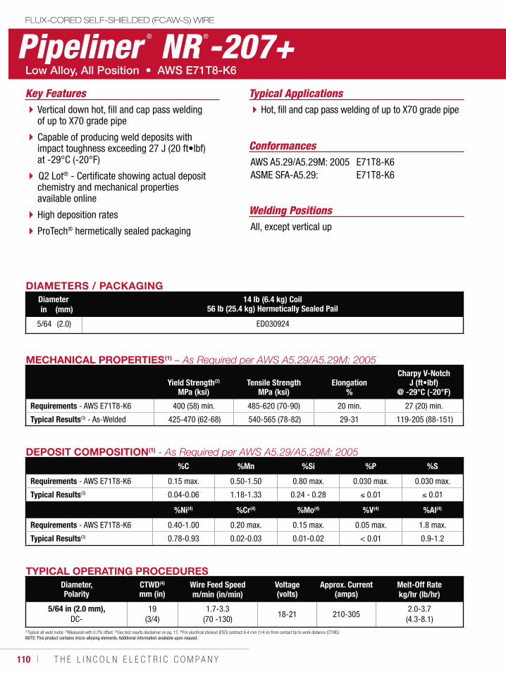
110 ı T H E L I N C O L N E L E C T R I C C O M P A N Y
FLUX-CORED SELF-SHIELDED (FCAW-S) WIRE
Pipeliner ® NR ®-207+
Welding Positions
Typical Applications
All, except vertical up
Hot, fill and cap pass welding of up to X70 grade pipe
ConformancesAWS A5.29/A5.29M: 2005ASME SFA-A5.29:
E71T8-K6E71T8-K6
Vertical down hot, fill and cap pass welding of up to X70 grade pipe
Capable of producing weld deposits with impact toughness exceeding 27 J (20 ft•lbf) at -29°C (-20°F)
Q2 Lot® - Certificate showing actual deposit chemistry and mechanical properties available online
High deposition rates
ProTech® hermetically sealed packaging
Key Features
DIAMETERS / PACKAGINGDiameter 14 lb (6.4 kg) Coil
56 lb (25.4 kg) Hermetically Sealed Pailin (mm)
5/64 (2.0) ED030924
TYPICAL OPERATING PROCEDURESDiameter, Polarity
CTWD(4)
mm (in)Wire Feed Speed Voltage
(volts)Approx. Current
(amps)Melt-Off Rate
m/min (in/min) kg/hr (lb/hr)
5/64 in (2.0 mm), DC-
19 (3/4)
1.7-3.3 (70 -130)
18-21 210-3052.0-3.7
(4.3-8.1)(1)Typical all weld metal. (2)Measured with 0.2% offset. (3)See test results disclaimer on pg. 12. (4)For electrical stickout (ESO) subtract 6.4 mm (1/4 in) from contact tip to work distance (CTWD).NOTE: This product contains micro-alloying elements. Additional information available upon request.
DEPOSIT COMPOSITION(1)
%C %Mn %Si %P %S
Requirements - AWS E71T8-K6 0.15 max. 0.50-1.50 0.80 max. 0.030 max. 0.030 max.
Typical Results(3) 0.04-0.06 1.18-1.33 0.24 - 0.28 0.01 0.01
%Ni(4) %Cr(4) %Mo(4) %V(4) %Al(4)
Requirements - AWS E71T8-K6 0.40-1.00 0.20 max. 0.15 max. 0.05 max. 1.8 max.
Typical Results(3) 0.78-0.93 0.02-0.03 0.01-0.02 < 0.01 0.9-1.2
MECHANICAL PROPERTIES(1)
Yield Strength(2)
MPa (ksi)Tensile Strength
MPa (ksi)Elongation
%
Charpy V-NotchJ (ft•lbf)
@ -29°C (-20°F)
Requirements - AWS E71T8-K6 400 (58) min. 485-620 (70-90) 20 min. 27 (20) min.
Typical Results(3) - As-Welded 425-470 (62-68) 540-565 (78-82) 29-31 119-205 (88-151)
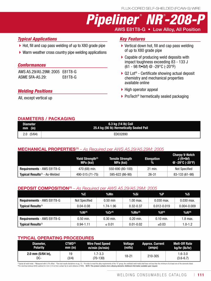
W E L D I N G C O N S U M A B L E S C A T A L O G ı 111
Pipeliner ® NR ®-208-PFLUX-CORED SELF-SHIELDED (FCAW-S) WIRE
Welding Positions
Typical Applications
All, except vertical up
Hot, fill and cap pass welding of up to X80 grade pipe
Warm weather cross country pipe welding applications
Vertical down hot, fill and cap pass welding of up to X80 grade pipe
Capable of producing weld deposits with impact toughness exceeding 83 - 133 J (61 - 98 ft•lbf) @ -29°C (-20°F)
Q2 Lot® - Certificate showing actual deposit chemistry and mechanical properties available online
High operator appeal
ProTech® hermetically sealed packaging
Conformances
Key Features
AWS A5.29/A5.29M: 2005ASME SFA-A5.29:
E81T8-GE81T8-G
DIAMETERS / PACKAGINGDiameter 6.3 kg (14 lb) Coil
25.4 kg (56 lb) Hermetically Sealed Pailmm (in)
2.0 (5/64) ED032890
MECHANICAL PROPERTIES(1)
Yield Strength(2)
MPa (ksi)Tensile Strength
MPa (ksi)Elongation
%
Charpy V-NotchJ (ft•lbf)
@ -29°C (-20°F)
Requirements - AWS E81T8-G 470 (68) min. 550-690 (80-100) 21 min. Not Specified
Typical Results(3) - As-Welded 490-515 (71-75) 595-622 (86-90) 26-31 83-133 (61-98)
TYPICAL OPERATING PROCEDURESDiameter, Polarity
CTWD(5)
mm (in)Wire Feed Speed Voltage
(volts)Approx. Current
(amps)Melt-Off Rate
m/min (in/min) kg/hr (lb/hr)
2.0 mm (5/64 in), DC-
19 (3/4)
1.7-3.3 (70-130)
18-21 210-3051.6-3.0
(3.6-6.7)(1)Typical all weld metal. (2)Measured with 0.2% offset. (3)See test results disclaimer on pg. 12. (4)In order to meet the alloy requirements of the “G” group, the undiluted weld metal shall have not less than the minimum of at least one of the elements listed. (5)For electrical stickout (ESO) subtract 6.4 mm (1/4 in) from contact tip to work distance (CTWD). NOTE: This product contains micro-alloying elements. Additional information available upon request.
DEPOSIT COMPOSITION(1)
%C %Mn %Si %P %S
Requirements - AWS E81T8-G Not Specified 0.50 min 1.00 max. 0.030 max. 0.030 max.
Typical Results(3) 0.04-0.08 1.74-1.96 0.32-0.37 0.012-0.019 0.004-0.009
%Ni(4) %Cr(4) %Mo(4) %V(4) %Al(4)
Requirements - AWS E81T8-G 0.50 min. 0.30 min. 0.20 min. 0.10 min. 1.8 max.
Typical Results(3) 0.94-1.11 0.01 0.01-0.02 0.03 1.0-1.2
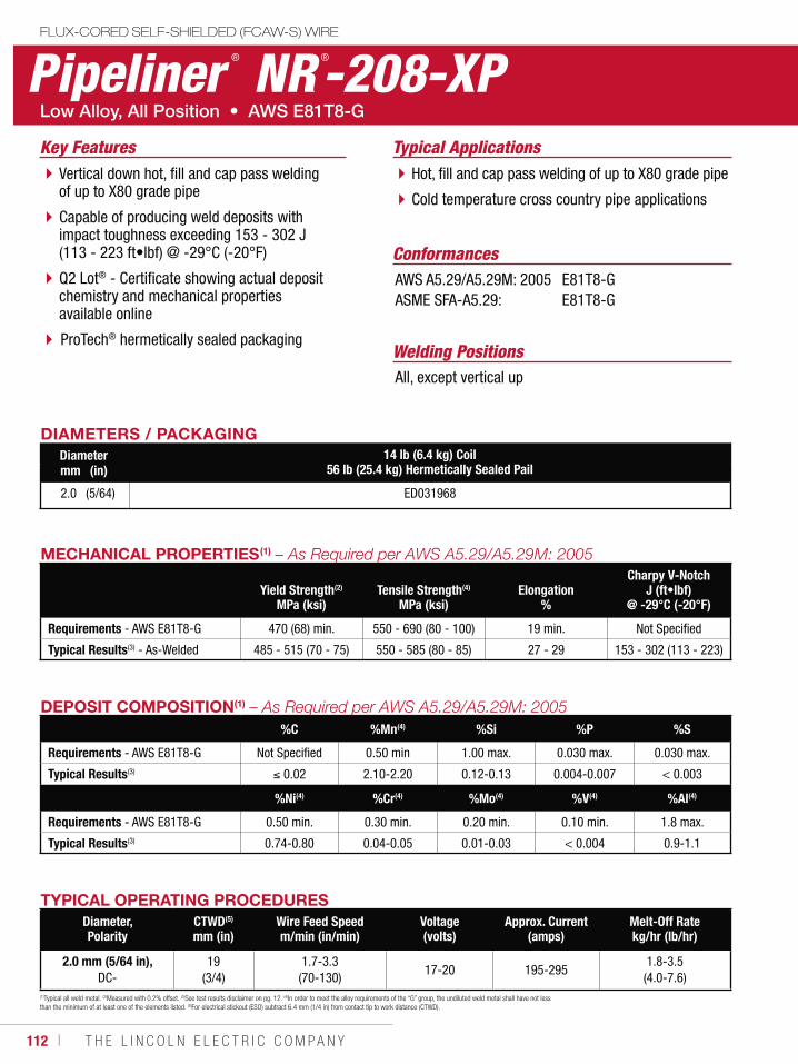
112 ı T H E L I N C O L N E L E C T R I C C O M P A N Y
FLUX-CORED SELF-SHIELDED (FCAW-S) WIRE
Pipeliner ® NR ®-208-XP
Welding Positions
Typical Applications
All, except vertical up
Hot, fill and cap pass welding of up to X80 grade pipe
Cold temperature cross country pipe applications
ConformancesAWS A5.29/A5.29M: 2005ASME SFA-A5.29:
E81T8-GE81T8-G
Vertical down hot, fill and cap pass welding of up to X80 grade pipe
Capable of producing weld deposits with impact toughness exceeding 153 - 302 J (113 - 223 ft•lbf) @ -29°C (-20°F)
Q2 Lot® - Certificate showing actual deposit chemistry and mechanical properties available online
ProTech® hermetically sealed packaging
Key Features
DIAMETERS / PACKAGINGDiameter 14 lb (6.4 kg) Coil
56 lb (25.4 kg) Hermetically Sealed Pailmm (in)
2.0 (5/64) ED031968
MECHANICAL PROPERTIES(1)
Yield Strength(2)
MPa (ksi)Tensile Strength(4)
MPa (ksi)Elongation
%
Charpy V-NotchJ (ft•lbf)
@ -29°C (-20°F)
Requirements - AWS E81T8-G 470 (68) min. 550 - 690 (80 - 100) 19 min. Not Specified
Typical Results(3) - As-Welded 485 - 515 (70 - 75) 550 - 585 (80 - 85) 27 - 29 153 - 302 (113 - 223)
TYPICAL OPERATING PROCEDURESDiameter, Polarity
CTWD(5)
mm (in)Wire Feed Speedm/min (in/min)
Voltage (volts)
Approx. Current(amps)
Melt-Off Ratekg/hr (lb/hr)
2.0 mm (5/64 in), DC-
19 (3/4)
1.7-3.3 (70-130)
17-20 195-2951.8-3.5
(4.0-7.6) (1)Typical all weld metal. (2)Measured with 0.2% offset. (3)See test results disclaimer on pg. 12. (4)In order to meet the alloy requirements of the “G” group, the undiluted weld metal shall have not less than the minimum of at least one of the elements listed. (5)For electrical stickout (ESO) subtract 6.4 mm (1/4 in) from contact tip to work distance (CTWD).
DEPOSIT COMPOSITION(1)
%C %Mn(4) %Si %P %S
Requirements - AWS E81T8-G Not Specified 0.50 min 1.00 max. 0.030 max. 0.030 max.
Typical Results(3) 0.02 2.10-2.20 0.12-0.13 0.004-0.007 < 0.003
%Ni(4) %Cr(4) %Mo(4) %V(4) %Al(4)
Requirements - AWS E81T8-G 0.50 min. 0.30 min. 0.20 min. 0.10 min. 1.8 max.
Typical Results(3) 0.74-0.80 0.04-0.05 0.01-0.03 < 0.004 0.9-1.1
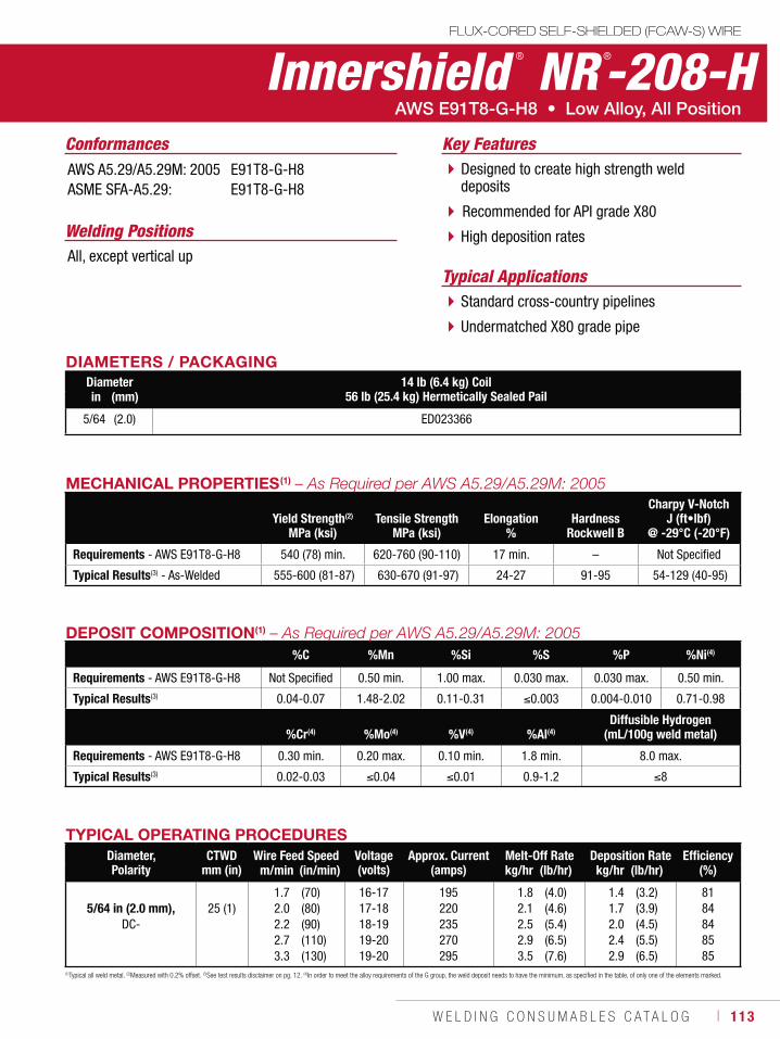
W E L D I N G C O N S U M A B L E S C A T A L O G ı 113
Innershield ® NR ®-208-HFLUX-CORED SELF-SHIELDED (FCAW-S) WIRE
Welding Positions
Typical ApplicationsAll, except vertical up
Standard cross-country pipelines
Undermatched X80 grade pipe
Designed to create high strength weld deposits
Recommended for API grade X80
High deposition rates
Conformances Key FeaturesAWS A5.29/A5.29M: 2005ASME SFA-A5.29:
E91T8-G-H8E91T8-G-H8
DIAMETERS / PACKAGINGDiameter 14 lb (6.4 kg) Coil
56 lb (25.4 kg) Hermetically Sealed Pailin (mm)
5/64 (2.0) ED023366
TYPICAL OPERATING PROCEDURESDiameter, Polarity
CTWDmm (in)
Wire Feed Speed Voltage (volts)
Approx. Current(amps)
Melt-Off Rate Deposition Rate Efficiency(%)m/min (in/min) kg/hr (lb/hr) kg/hr (lb/hr)
5/64 in (2.0 mm),DC-
25 (1)1.72.02.22.73.3
(70)(80)(90)(110)(130)
16-1717-1818-1919-2019-20
195220235270295
1.82.12.52.93.5
(4.0)(4.6)(5.4)(6.5)(7.6)
1.41.72.02.42.9
(3.2)(3.9)(4.5)(5.5)(6.5)
8184848585
(1)Typical all weld metal. (2)Measured with 0.2% offset. (3)See test results disclaimer on pg. 12. (4)In order to meet the alloy requirements of the G group, the weld deposit needs to have the minimum, as specified in the table, of only one of the elements marked.
MECHANICAL PROPERTIES(1)
Yield Strength(2)
MPa (ksi)Tensile Strength
MPa (ksi)Elongation
%Hardness
Rockwell B
Charpy V-NotchJ (ft•lbf)
@ -29°C (-20°F)
Requirements - AWS E91T8-G-H8 540 (78) min. 620-760 (90-110) 17 min. – Not Specified
Typical Results(3) - As-Welded 555-600 (81-87) 630-670 (91-97) 24-27 91-95 54-129 (40-95)
DEPOSIT COMPOSITION(1)
%C %Mn %Si %S %P %Ni(4)
Requirements - AWS E91T8-G-H8 Not Specified 0.50 min. 1.00 max. 0.030 max. 0.030 max. 0.50 min.
Typical Results(3) 0.04-0.07 1.48-2.02 0.11-0.31 0.003 0.004-0.010 0.71-0.98
%Cr(4) %Mo(4) %V(4) %Al(4)Diffusible Hydrogen
(mL/100g weld metal)
Requirements - AWS E91T8-G-H8 0.30 min. 0.20 max. 0.10 min. 1.8 min. 8.0 max.
Typical Results(3) 0.02-0.03 0.04 0.01 0.9-1.2 8
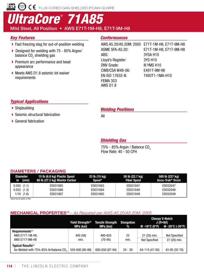
114 ı T H E L I N C O L N E L E C T R I C C O M P A N Y
UltraCore ® 71A85
Welding Positions
Typical Applications
All
Shipbuilding
Seismic structural fabrication
General fabrication
Fast freezing slag for out-of-position welding
Designed for welding with 75 - 85% Argon/ balance CO2 shielding gas
Premium arc performance and bead appearance
Meets AWS D1.8 seismic lot waiver requirements
Conformances
Shielding Gas75% - 85% Argon / Balance CO2Flow Rate: 40 - 50 CFH
Key FeaturesAWS A5.20/A5.20M: 2005ASME SFA-A5.20:ABS: Lloyd’s Register:DNV Grade: CWB/CSA W48-06: EN ISO 17632-B:FEMA 353 AWS D1.8
E71T-1M-H8, E71T-9M-H8E71T-1M-H8, E71T-9M-H83YSA H103YS H10III YMS H10E491T-9M H8T493T1-1MA-H10
DIAMETERS / PACKAGINGDiameter 15 lb (6.8 kg) Plastic Spool
60 lb (27.2 kg) Master Carton33 lb (15 kg)
Spool*50 lb (22.7 kg)
Fiber Spool500 lb (227 kg)
Accu-Trak® Drumin (mm)
0.0450.0521/16
(1.1)(1.3)(1.6)
ED031885ED031886ED031887
ED031663ED031664ED031665
ED031847ED031848ED031849
ED032047ED032048ED032049
MECHANICAL PROPERTIES(1)
Yield Strength(2) Tensile Strength ElongationCharpy V-Notch
J (ft•lbf)MPa (ksi) MPa (ksi) % @ -18°C (0°F) @ -29°C (-20°F)
Requirements(4)
AWS E71T-1M-H8,AWS E71T-9M-H8
400 (58)
min.
480-655 (70-95)
22
min.27 (20) min. Not SpecifiedNot Specified 27 (20) min.
Typical Results(3)
As-Welded with 75%-85% Ar/balance CO2 550-600 (80-88) 600-650 (87-94) 24 - 26 64-115 (47-85) 43-95 (32-70)
FLUX-CORED GAS-SHIELDED (FCAW-G) WIREStructural Welding Code Seismic Supplement
*Spool may be plastic or fiber.
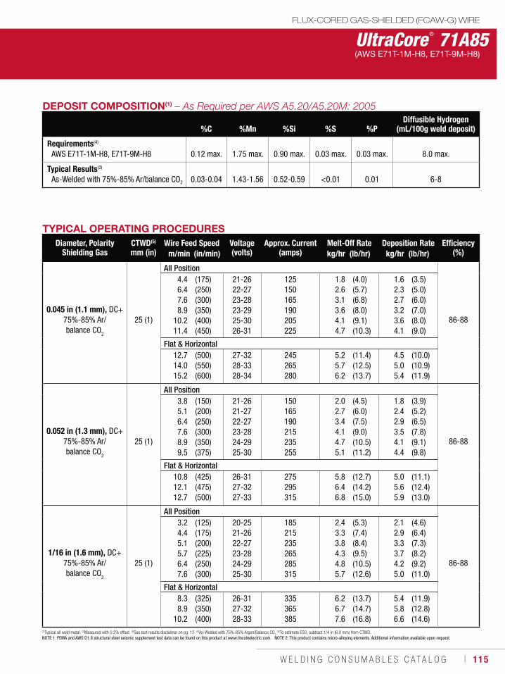
W E L D I N G C O N S U M A B L E S C A T A L O G ı 115
UltraCore ® 71A85(AWS E71T-1M-H8, E71T-9M-H8)
DEPOSIT COMPOSITION(1)
%C
%Mn
%Si
%S
%P
Diffusible Hydrogen (mL/100g weld deposit)
Requirements(4)
AWS E71T-1M-H8, E71T-9M-H8 0.12 max. 1.75 max. 0.90 max. 0.03 max. 0.03 max. 8.0 max.
Typical Results(3)
As-Welded with 75%-85% Ar/balance CO2 0.03-0.04 1.43-1.56 0.52-0.59 <0.01 0.01 6-8
TYPICAL OPERATING PROCEDURESDiameter, Polarity
Shielding GasCTWD(5)
mm (in)Wire Feed Speed Voltage
(volts)Approx. Current
(amps)Melt-Off Rate Deposition Rate Efficiency
(%)m/min (in/min) kg/hr (lb/hr) kg/hr (lb/hr)
0.045 in (1.1 mm), DC+75%-85% Ar/ balance CO2
25 (1)
All Position
86-88
4.46.47.68.9
10.211.4
(175)(250)(300)(350)(400)(450)
21-2622-2723-2823-2925-3026-31
125150165190205225
1.82.63.13.64.14.7
(4.0)(5.7)(6.8)(8.0)(9.1)(10.3)
1.62.32.73.23.64.1
(3.5)(5.0)(6.0)(7.0)(8.0)(9.0)
Flat & Horizontal12.714.015.2
(500)(550)(600)
27-3228-3328-34
245265280
5.25.76.2
(11.4)(12.5)(13.7)
4.55.05.4
(10.0)(10.9)(11.9)
0.052 in (1.3 mm), DC+75%-85% Ar/ balance CO
2
25 (1)
All Position
86-88
3.85.16.47.68.99.5
(150)(200)(250)(300)(350)(375)
21-2621-2722-2723-2824-2925-30
150165190215235255
2.02.73.44.14.75.1
(4.5)(6.0)(7.5)(9.0)(10.5)(11.2)
1.82.42.93.54.14.4
(3.9)(5.2)(6.5)(7.8)(9.1)(9.8)
Flat & Horizontal10.812.112.7
(425)(475)(500)
26-3127-3227-33
275295315
5.86.46.8
(12.7)(14.2)(15.0)
5.05.65.9
(11.1)(12.4)(13.0)
1/16 in (1.6 mm), DC+75%-85% Ar/ balance CO
2
25 (1)
All Position
86-88
3.24.45.15.76.47.6
(125)(175)(200)(225)(250)(300)
20-2521-2622-2723-2824-2925-30
185215235265285315
2.43.33.84.34.85.7
(5.3)(7.4)(8.4)(9.5)(10.5)(12.6)
2.12.93.33.74.25.0
(4.6)(6.4)(7.3)(8.2)(9.2)(11.0)
Flat & Horizontal8.38.9
10.2
(325)(350)(400)
26-3127-3228-33
335365385
6.26.77.6
(13.7)(14.7)(16.8)
5.45.86.6
(11.9)(12.8)(14.6)
(1)Typical all weld metal. (2)Measured with 0.2% offset. (3)See test results disclaimer on pg. 12. (4)As-Welded with 75%-85% Argon/Balance CO2
(5)To estimate ESO, subtract 1/4 in (6.0 mm) from CTWD.NOTE 1: FEMA and AWS D1.8 structural steel seismic supplement test data can be found on this product at www.lincolnelectric.com. NOTE 2: This product contains micro-alloying elements. Additional information available upon request.
FLUX-CORED GAS-SHIELDED (FCAW-G) WIRE
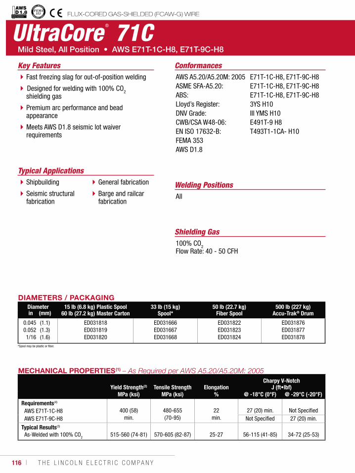
116 ı T H E L I N C O L N E L E C T R I C C O M P A N Y
Structural Welding Code Seismic Supplement
UltraCore ® 71C
Welding Positions
Typical Applications
All
Shipbuilding
Seismic structural fabrication
General fabrication
Barge and railcar fabrication
Fast freezing slag for out-of-position welding
Designed for welding with 100% CO2 shielding gas
Premium arc performance and bead appearance
Meets AWS D1.8 seismic lot waiver requirements
Conformances
Shielding Gas100% CO2Flow Rate: 40 - 50 CFH
Key FeaturesAWS A5.20/A5.20M: 2005ASME SFA-A5.20:ABS: Lloyd’s Register: DNV Grade:CWB/CSA W48-06: EN ISO 17632-B:FEMA 353AWS D1.8
E71T-1C-H8, E71T-9C-H8E71T-1C-H8, E71T-9C-H8E71T-1C-H8, E71T-9C-H83YS H10III YMS H10E491T-9 H8T493T1-1CA- H10
DIAMETERS / PACKAGINGDiameter 15 lb (6.8 kg) Plastic Spool
60 lb (27.2 kg) Master Carton33 lb (15 kg)
Spool*50 lb (22.7 kg)
Fiber Spool500 lb (227 kg)
Accu-Trak® Drumin (mm)
0.0450.0521/16
(1.1)(1.3)(1.6)
ED031818ED031819ED031820
ED031666ED031667ED031668
ED031822ED031823ED031824
ED031876ED031877ED031878
MECHANICAL PROPERTIES(1)
Yield Strength(2) Tensile Strength ElongationCharpy V-Notch
J (ft•lbf)MPa (ksi) MPa (ksi) % @ -18°C (0°F) @ -29°C (-20°F)
Requirements(4)
AWS E71T-1C-H8AWS E71T-9C-H8
400 (58)
min.
480-655 (70-95)
22
min.
27 (20) min.
Not Specified
Not Specified 27 (20) min.
Typical Results(3)
As-Welded with 100% CO2 515-560 (74-81) 570-605 (82-87) 25-27 56-115 (41-85) 34-72 (25-53)
FLUX-CORED GAS-SHIELDED (FCAW-G) WIRE
*Spool may be plastic or fiber.
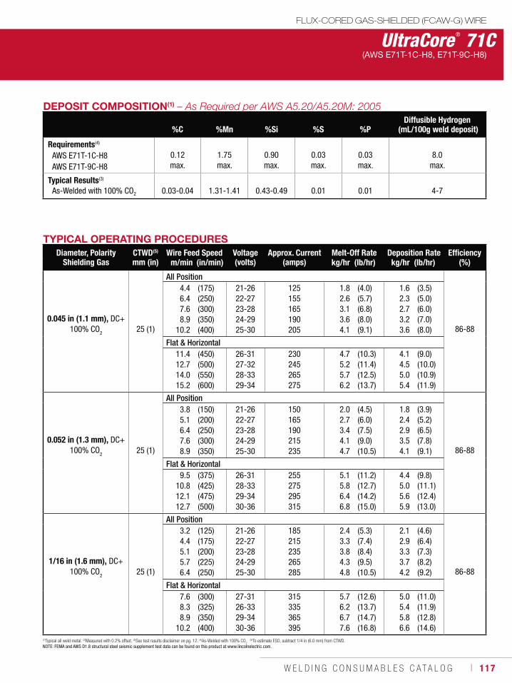
W E L D I N G C O N S U M A B L E S C A T A L O G ı 117
FLUX-CORED GAS-SHIELDED (FCAW-G) WIRE
UltraCore ® 71C(AWS E71T-1C-H8, E71T-9C-H8)
DEPOSIT COMPOSITION(1)
%C %Mn %Si %S %PDiffusible Hydrogen
(mL/100g weld deposit)
Requirements(4)
AWS E71T-1C-H8AWS E71T-9C-H8
0.12 max.
1.75 max.
0.90 max.
0.03 max.
0.03 max.
8.0 max.
Typical Results(3)
As-Welded with 100% CO2 0.03-0.04 1.31-1.41 0.43-0.49 0.01 0.01 4-7
TYPICAL OPERATING PROCEDURESDiameter, Polarity
Shielding GasCTWD(5)
mm (in)Wire Feed Speed Voltage
(volts)Approx. Current
(amps)Melt-Off Rate Deposition Rate Efficiency
(%)m/min (in/min) kg/hr (lb/hr) kg/hr (lb/hr)
0.045 in (1.1 mm), DC+100% CO2 25 (1)
All Position
86-88
4.46.47.68.9
10.2
(175)(250)(300)(350)(400)
21-2622-2723-2824-2925-30
125155165190205
1.82.63.13.64.1
(4.0)(5.7)(6.8)(8.0)(9.1)
1.62.32.73.23.6
(3.5)(5.0)(6.0)(7.0)(8.0)
Flat & Horizontal11.412.714.015.2
(450)(500)(550)(600)
26-3127-3228-3329-34
230245265275
4.75.25.76.2
(10.3)(11.4)(12.5)(13.7)
4.14.55.05.4
(9.0)(10.0)(10.9)(11.9)
0.052 in (1.3 mm), DC+100% CO
2 25 (1)
All Position
86-88
3.85.16.47.68.9
(150)(200)(250)(300)(350)
21-2622-2723-2824-2925-30
150165190215235
2.02.73.44.14.7
(4.5)(6.0)(7.5)(9.0)(10.5)
1.82.42.93.54.1
(3.9)(5.2)(6.5)(7.8)(9.1)
Flat & Horizontal9.5
10.812.112.7
(375)(425)(475)(500)
26-3128-3329-3430-36
255275295315
5.1 5.86.46.8
(11.2) (12.7)(14.2)(15.0)
4.45.05.65.9
(9.8) (11.1)(12.4)(13.0)
1/16 in (1.6 mm), DC+100% CO
2 25 (1)
All Position
86-88
3.24.45.15.76.4
(125)(175)(200)(225)(250)
21-2622-2723-2824-2925-30
185215235265285
2.43.33.84.34.8
(5.3)(7.4)(8.4)(9.5)(10.5)
2.12.93.33.74.2
(4.6)(6.4)(7.3)(8.2)(9.2)
Flat & Horizontal7.68.38.9
10.2
(300)(325)(350)(400)
27-3126-3329-3430-36
315335365395
5.76.26.77.6
(12.6)(13.7)(14.7)(16.8)
5.05.45.86.6
(11.0)(11.9)(12.8)(14.6)
(1)Typical all weld metal. (2)Measured with 0.2% offset. (3)See test results disclaimer on pg. 12. (4)As-Welded with 100% CO2 (5)To estimate ESO, subtract 1/4 in (6.0 mm) from CTWD.
NOTE: FEMA and AWS D1.8 structural steel seismic supplement test data can be found on this product at www.lincolnelectric.com.
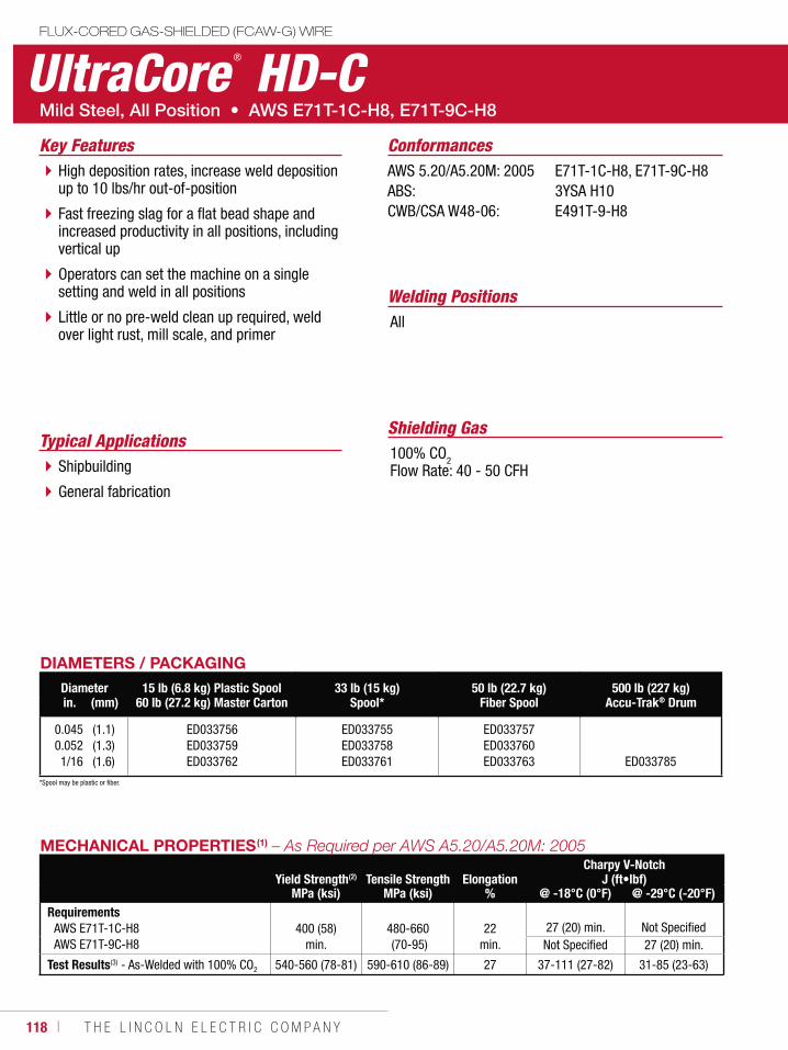
118 ı T H E L I N C O L N E L E C T R I C C O M P A N Y
UltraCore ® HD-CFLUX-CORED GAS-SHIELDED (FCAW-G) WIRE
Welding Positions
Typical Applications
All
Shipbuilding
General fabrication
High deposition rates, increase weld deposition up to 10 lbs/hr out-of-position
Fast freezing slag for a flat bead shape and increased productivity in all positions, including vertical up
Operators can set the machine on a single setting and weld in all positions
Little or no pre-weld clean up required, weld over light rust, mill scale, and primer
Conformances
Shielding Gas100% CO2Flow Rate: 40 - 50 CFH
Key FeaturesAWS 5.20/A5.20M: 2005ABS:CWB/CSA W48-06:
E71T-1C-H8, E71T-9C-H83YSA H10E491T-9-H8
DIAMETERS / PACKAGINGDiameter 15 lb (6.8 kg) Plastic Spool
60 lb (27.2 kg) Master Carton33 lb (15 kg)
Spool*50 lb (22.7 kg)
Fiber Spool500 lb (227 kg)
Accu-Trak® Drumin. (mm)
0.0450.0521/16
(1.1)(1.3)(1.6)
ED033756ED033759ED033762
ED033755ED033758ED033761
ED033757ED033760ED033763 ED033785
MECHANICAL PROPERTIES(1)
Yield Strength(2) Tensile Strength ElongationCharpy V-Notch
J (ft•lbf)MPa (ksi) MPa (ksi) % @ -18°C (0°F) @ -29°C (-20°F)
RequirementsAWS E71T-1C-H8AWS E71T-9C-H8
400 (58) min.
480-660 (70-95)
22 min.
27 (20) min. Not SpecifiedNot Specified 27 (20) min.
Test Results(3) - As-Welded with 100% CO2 540-560 (78-81) 590-610 (86-89) 27 37-111 (27-82) 31-85 (23-63)
*Spool may be plastic or fiber.
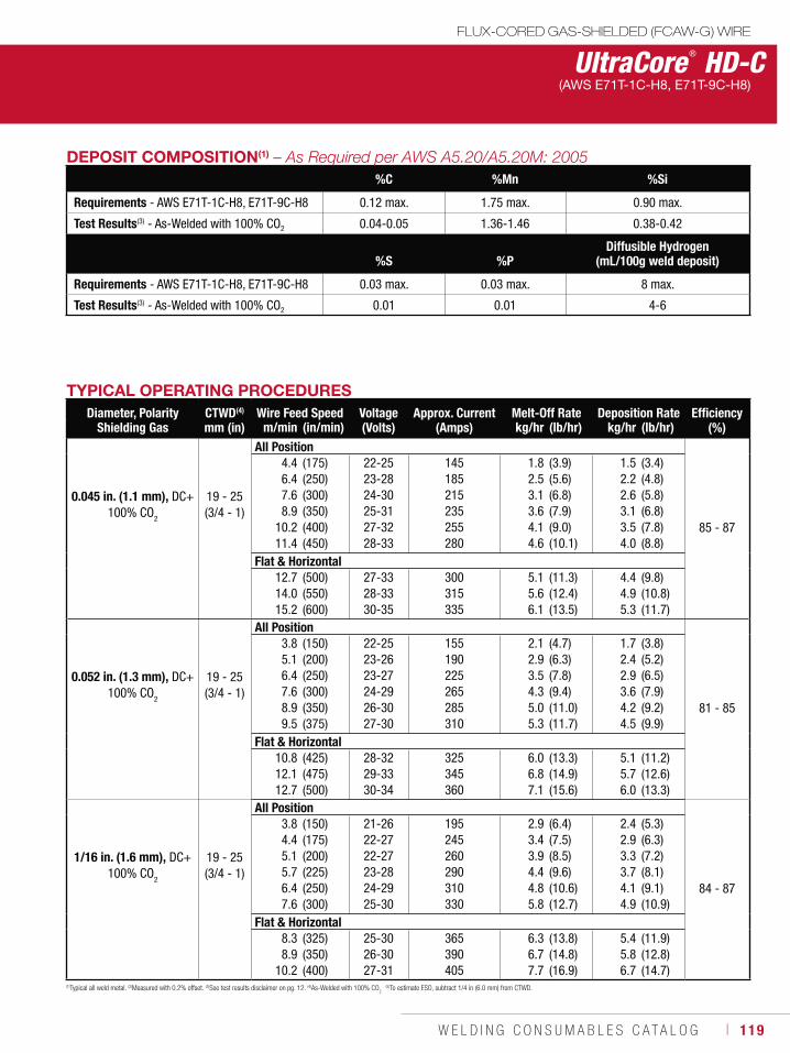
W E L D I N G C O N S U M A B L E S C A T A L O G ı 119
FLUX-CORED GAS-SHIELDED (FCAW-G) WIRE
UltraCore ® HD-C(AWS E71T-1C-H8, E71T-9C-H8)
(1)Typical all weld metal. (2)Measured with 0.2% offset. (3)See test results disclaimer on pg. 12. (4)As-Welded with 100% CO2 (5)To estimate ESO, subtract 1/4 in (6.0 mm) from CTWD.
DEPOSIT COMPOSITION(1)
%C %Mn %Si
Requirements - AWS E71T-1C-H8, E71T-9C-H8 0.12 max. 1.75 max. 0.90 max.
Test Results(3) - As-Welded with 100% CO2 0.04-0.05 1.36-1.46 0.38-0.42
%S %PDiffusible Hydrogen
(mL/100g weld deposit)
Requirements - AWS E71T-1C-H8, E71T-9C-H8 0.03 max. 0.03 max. 8 max.
Test Results(3) - As-Welded with 100% CO2 0.01 0.01 4-6
TYPICAL OPERATING PROCEDURESDiameter, Polarity
Shielding GasCTWD(4)
mm (in)Wire Feed Speed Voltage
(Volts)Approx. Current
(Amps)Melt-Off Rate Deposition Rate Efficiency
(%)m/min (in/min) kg/hr (lb/hr) kg/hr (lb/hr)
0.045 in. (1.1 mm), DC+100% CO2
19 - 25(3/4 - 1)
All Position
85 - 87
4.46.47.68.9
10.211.4
(175)(250)(300)(350)(400)(450)
22-2523-2824-3025-3127-3228-33
145185215235255280
1.8 2.5 3.1 3.6 4.1 4.6
(3.9)(5.6)(6.8)(7.9)(9.0)(10.1)
1.52.22.63.13.54.0
(3.4)(4.8)(5.8)(6.8)(7.8)(8.8)
Flat & Horizontal12.714.015.2
(500)(550)(600)
27-3328-3330-35
300315335
5.15.66.1
(11.3)(12.4)(13.5)
4.44.95.3
(9.8)(10.8)(11.7)
0.052 in. (1.3 mm), DC+100% CO
2
19 - 25(3/4 - 1)
All Position
81 - 85
3.85.16.47.68.99.5
(150)(200)(250)(300)(350)(375)
22-2523-2623-2724-2926-3027-30
155190225265285310
2.12.93.54.35.05.3
(4.7)(6.3)(7.8)(9.4)(11.0)(11.7)
1.72.42.93.64.24.5
(3.8)(5.2)(6.5)(7.9)(9.2)(9.9)
Flat & Horizontal10.812.112.7
(425)(475)(500)
28-3229-3330-34
325345360
6.0 6.87.1
(13.3)(14.9)(15.6)
5.1 5.76.0
(11.2)(12.6)(13.3)
1/16 in. (1.6 mm), DC+100% CO
2
19 - 25(3/4 - 1)
All Position
84 - 87
3.84.45.15.76.47.6
(150)(175)(200)(225)(250)(300)
21-2622-2722-2723-2824-2925-30
195245260290310330
2.93.43.9 4.44.85.8
(6.4)(7.5)(8.5)(9.6)(10.6)(12.7)
2.42.93.33.74.14.9
(5.3)(6.3)(7.2)(8.1)(9.1)(10.9)
Flat & Horizontal8.38.9
10.2
(325)(350)(400)
25-3026-3027-31
365390405
6.36.77.7
(13.8)(14.8)(16.9)
5.45.86.7
(11.9)(12.8)(14.7)
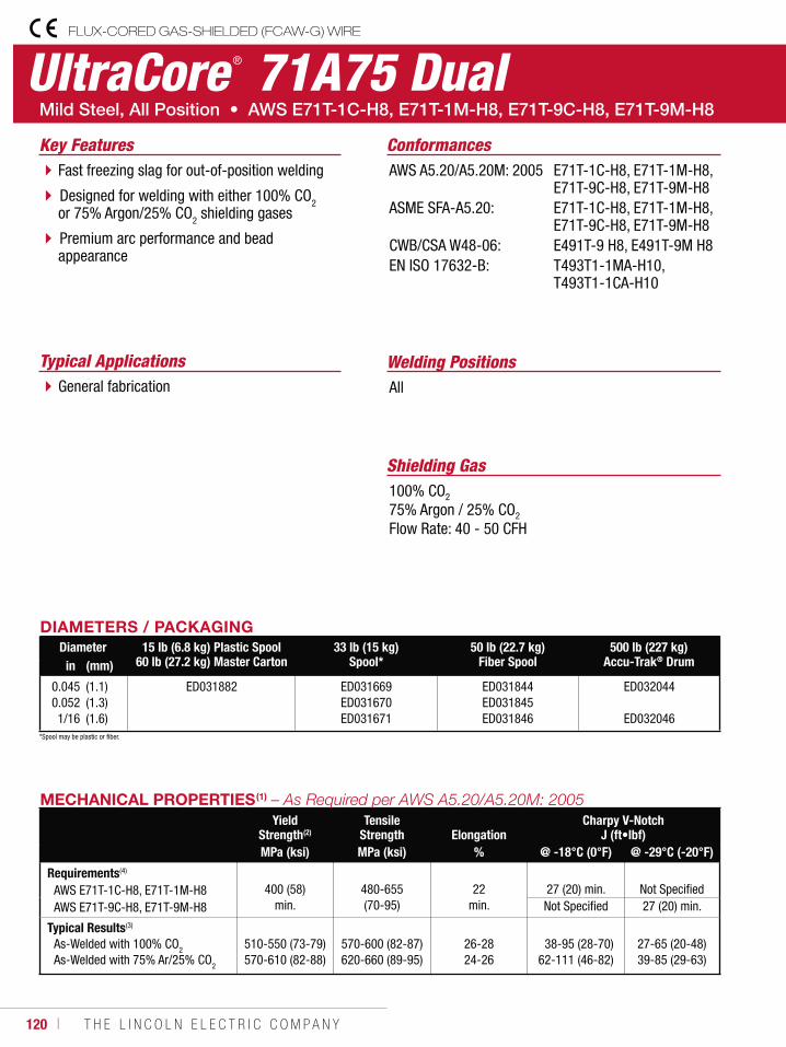
120 ı T H E L I N C O L N E L E C T R I C C O M P A N Y
UltraCore ® 71A75 DualFLUX-CORED GAS-SHIELDED (FCAW-G) WIRE
Welding PositionsTypical ApplicationsAllGeneral fabrication
Fast freezing slag for out-of-position welding
Designed for welding with either 100% CO2 or 75% Argon/25% CO2 shielding gases
Premium arc performance and bead appearance
Conformances
Shielding Gas100% CO2
75% Argon / 25% CO2
Flow Rate: 40 - 50 CFH
Key FeaturesAWS A5.20/A5.20M: 2005
ASME SFA-A5.20:
CWB/CSA W48-06:EN ISO 17632-B:
E71T-1C-H8, E71T-1M-H8, E71T-9C-H8, E71T-9M-H8E71T-1C-H8, E71T-1M-H8, E71T-9C-H8, E71T-9M-H8E491T-9 H8, E491T-9M H8T493T1-1MA-H10, T493T1-1CA-H10
DIAMETERS / PACKAGINGDiameter 15 lb (6.8 kg) Plastic Spool
60 lb (27.2 kg) Master Carton33 lb (15 kg)
Spool*50 lb (22.7 kg)
Fiber Spool500 lb (227 kg)
Accu-Trak® Drumin (mm)
0.0450.0521/16
(1.1)(1.3)(1.6)
ED031882 ED031669ED031670ED031671
ED031844ED031845ED031846
ED032044
ED032046
MECHANICAL PROPERTIES(1)
Yield Strength(2)
Tensile Strength Elongation
Charpy V-NotchJ (ft•lbf)
MPa (ksi) MPa (ksi) % @ -18°C (0°F) @ -29°C (-20°F)
Requirements(4)
AWS E71T-1C-H8, E71T-1M-H8 AWS E71T-9C-H8, E71T-9M-H8
400 (58)
min.
480-655 (70-95)
22
min.27 (20) min. Not SpecifiedNot Specified 27 (20) min.
Typical Results(3)
As-Welded with 100% CO2
As-Welded with 75% Ar/25% CO2
510-550 (73-79)570-610 (82-88)
570-600 (82-87)620-660 (89-95)
26-2824-26
38-95 (28-70)62-111 (46-82)
27-65 (20-48)39-85 (29-63)
*Spool may be plastic or fiber.

W E L D I N G C O N S U M A B L E S C A T A L O G ı 121
UltraCore ® 71A75 DualFLUX-CORED GAS-SHIELDED (FCAW-G) WIRE
(AWS E71T-1C-H8, E71T-1M-H8, E71T-9C-H8, E71T-9M-H8)
DEPOSIT COMPOSITION(1) – As Required per AWS A5.20/A5.20M: 2005
%C %Mn %Si %S %PDiffusible Hydrogen
(mL/100g weld deposit)
Requirements(4)
AWS E71T-1C-H8, E71T-1M-H8 AWS E71T-9C-H8, E71T-9M-H8
0.12 max.
1.75 max.
0.90 max.
0.03 max.
0.03 max.
8.0 max.
Typical Results(3)
As-Welded with 100% CO2
As-Welded with 75% Ar/25% CO2
0.03-0.040.03-0.04
1.28-1.411.45-1.60
0.42-0.490.54-0.62
0.010.01
0.01-0.020.01-0.02
3-84-8
TYPICAL OPERATING PROCEDURESDiameter, PolarityShielding Gas(5)
CTWD(6)
mm (in)Wire Feed Speed Voltage
(volts)Approx. Current
(amps)Melt-Off Rate Deposition Rate Efficiency
(%)m/min (in/min) kg/hr (lb/hr) kg/hr (lb/hr)
0.045 in (1.1 mm), DC+ 75% Ar/25% CO2 25 (1)
All Position
86-88
4.46.47.68.9
10.2
(175)(250)(300)(350)(400)
20-2521-2622-2723-2824-29
135150165190205
1.82.63.13.64.1
(4.0)(5.7)(6.8)(8.0)(9.1)
1.62.32.73.23.6
(3.5)(5.0)(6.0)(7.0)(8.0)
Flat & Horizontal11.412.714.015.2
(450)(500)(550)(600)
25-30 26-3127-3227-33
225 245265285
4.7 5.25.76.2
(10.3)(11.4)(12.5)(13.7)
4.14.55.05.4
(9.0)(10.0)(10.9)(11.9)
0.052 in (1.3 mm), DC+ 75% Ar/25% CO
2 25 (1)
All Position
86-88
3.85.16.47.68.9
(150)(200)(250)(300)(350)
20-2521-2622-2723-2824-29
155165190215235
2.02.73.44.14.7
(4.5)(6.0)(7.5)(9.0)(10.5)
1.82.42.93.54.1
(3.9)(5.2)(6.5)(7.8)(9.1)
Flat & Horizontal9.5
10.812.112.7
(375)(425)(475)(500)
25-3027-3128-3329-35
255275295325
5.15.86.46.8
(11.2)(12.7)(14.2)(15.0)
4.45.05.65.9
(9.8)(11.1)(12.4)(13.0)
1/16 in (1.6 mm), DC+ 75% Ar/25% CO
2 25 (1)
All Position
86-88
3.24.45.15.76.4
(125)(175)(200)(225)(250)
20-2521-2622-2723-2824-29
195215235265285
2.43.33.84.34.8
(5.3)(7.4)(8.4)(9.5)(10.5)
2.12.93.33.74.2
(4.6)(6.4)(7.3)(8.2)(9.2)
Flat & Horizontal7.68.38.9
10.2
(300)(325)(350)(400)
25-31 25-3226-3328-35
315335365405
5.76.26.77.6
(12.6)(13.7)(14.7)(16.8)
5.05.45.86.6
(11.0)(11.9)(12.8)(14.6)
(1)Typical all weld metal. (2)Measured with 0.2% offset. (3)See test results disclaimer on pg. 12. (4)As-Welded with 100% CO2 & As-Welded 75% Argon / 25% CO
2. (5) When welding under CO
2, increase voltage by 1 Volt. (6)To estimate ESO, subtract 1/4 in (6.0 mm) from CTWD.
NOTE: This product contains micro-alloying elements. Additional information available upon request.
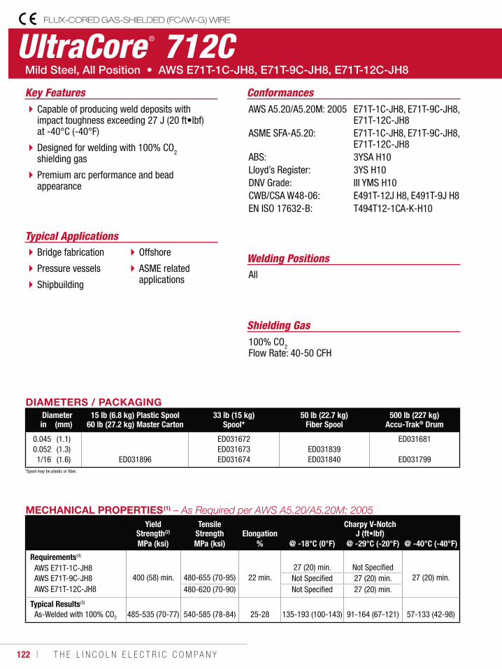
122 ı T H E L I N C O L N E L E C T R I C C O M P A N Y
UltraCore ® 712CFLUX-CORED GAS-SHIELDED (FCAW-G) WIRE
Welding Positions
Typical Applications
All
Bridge fabrication
Pressure vessels
Shipbuilding
Offshore
ASME related applications
Capable of producing weld deposits with impact toughness exceeding 27 J (20 ft•lbf) at -40°C (-40°F)
Designed for welding with 100% CO2 shielding gas
Premium arc performance and bead appearance
Conformances
Shielding Gas100% CO2Flow Rate: 40-50 CFH
Key FeaturesAWS A5.20/A5.20M: 2005
ASME SFA-A5.20:
ABS: Lloyd’s Register:DNV Grade:CWB/CSA W48-06:EN ISO 17632-B:
E71T-1C-JH8, E71T-9C-JH8, E71T-12C-JH8E71T-1C-JH8, E71T-9C-JH8, E71T-12C-JH83YSA H103YS H10III YMS H10E491T-12J H8, E491T-9J H8T494T12-1CA-K-H10
DIAMETERS / PACKAGINGDiameter 15 lb (6.8 kg) Plastic Spool
60 lb (27.2 kg) Master Carton33 lb (15 kg)
Spool*50 lb (22.7 kg)
Fiber Spool500 lb (227 kg)
Accu-Trak® Drumin (mm)
0.0450.0521/16
(1.1)(1.3)(1.6) ED031896
ED031672ED031673ED031674
ED031839ED031840
ED031681
ED031799
MECHANICAL PROPERTIES(1)
Yield Strength(2)
Tensile Strength Elongation
Charpy V-NotchJ (ft•lbf)
MPa (ksi) MPa (ksi) % @ -18°C (0°F) @ -29°C (-20°F) @ -40°C (-40°F)
Requirements(4)
AWS E71T-1C-JH8 AWS E71T-9C-JH8AWS E71T-12C-JH8
400 (58) min. 480-655 (70-95)
22 min.27 (20) min. Not Specified
27 (20) min.Not Specified 27 (20) min.480-620 (70-90) Not Specified 27 (20) min.
Typical Results(3)
As-Welded with 100% CO2 485-535 (70-77) 540-585 (78-84) 25-28 135-193 (100-143) 91-164 (67-121) 57-133 (42-98)
*Spool may be plastic or fiber.
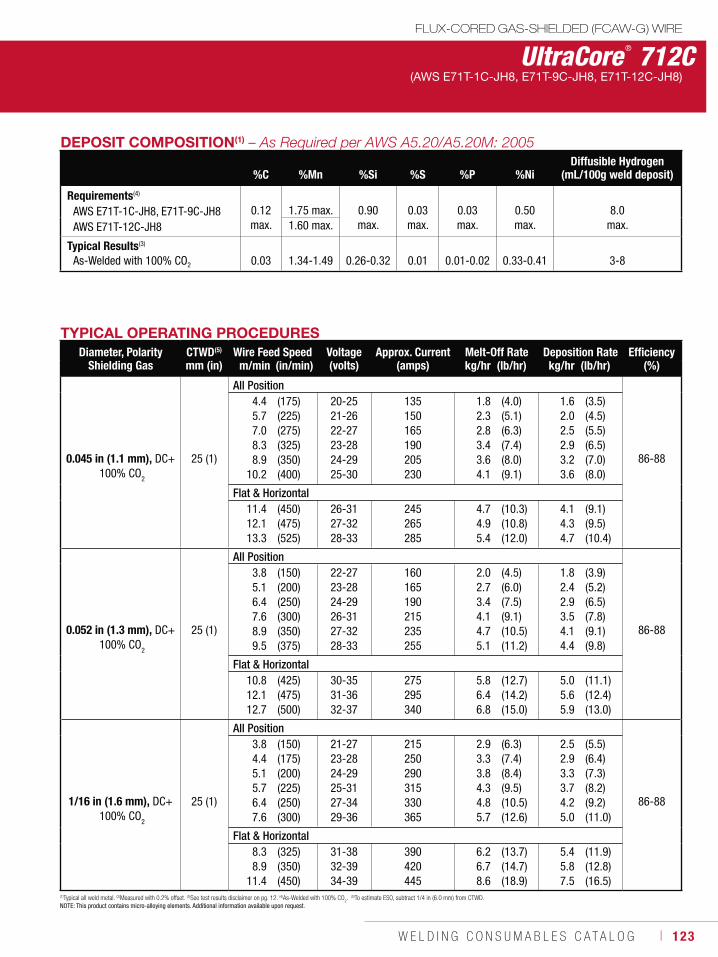
W E L D I N G C O N S U M A B L E S C A T A L O G ı 123
UltraCore ® 712CFLUX-CORED GAS-SHIELDED (FCAW-G) WIRE
(AWS E71T-1C-JH8, E71T-9C-JH8, E71T-12C-JH8)
DEPOSIT COMPOSITION(1)
%C %Mn %Si %S %P %NiDiffusible Hydrogen
(mL/100g weld deposit)
Requirements(4)
AWS E71T-1C-JH8, E71T-9C-JH8AWS E71T-12C-JH8
0.12 max.
1.75 max. 0.90 max.
0.03 max.
0.03 max.
0.50 max.
8.0 max.1.60 max.
Typical Results(3)
As-Welded with 100% CO2 0.03 1.34-1.49 0.26-0.32 0.01 0.01-0.02 0.33-0.41 3-8
TYPICAL OPERATING PROCEDURESDiameter, Polarity
Shielding GasCTWD(5)
mm (in)Wire Feed Speed Voltage
(volts)Approx. Current
(amps)Melt-Off Rate Deposition Rate Efficiency
(%)m/min (in/min) kg/hr (lb/hr) kg/hr (lb/hr)
0.045 in (1.1 mm), DC+ 100% CO2
25 (1)
All Position
86-88
4.45.77.08.38.9
10.2
(175)(225)(275)(325)(350)(400)
20-2521-2622-2723-2824-2925-30
135150165190205230
1.82.32.83.43.64.1
(4.0)(5.1)(6.3)(7.4)(8.0)(9.1)
1.62.02.52.93.23.6
(3.5)(4.5)(5.5)(6.5)(7.0)(8.0)
Flat & Horizontal11.412.113.3
(450)(475)(525)
26-3127-3228-33
245265285
4.74.95.4
(10.3)(10.8)(12.0)
4.14.34.7
(9.1)(9.5)(10.4)
0.052 in (1.3 mm), DC+ 100% CO
2
25 (1)
All Position
86-88
3.85.16.47.68.99.5
(150)(200)(250)(300)(350)(375)
22-2723-2824-2926-3127-3228-33
160165190215235255
2.02.73.44.14.75.1
(4.5)(6.0)(7.5)(9.1)(10.5)(11.2)
1.82.42.93.54.14.4
(3.9)(5.2)(6.5)(7.8)(9.1)(9.8)
Flat & Horizontal10.812.112.7
(425)(475)(500)
30-3531-3632-37
275295340
5.86.46.8
(12.7)(14.2)(15.0)
5.05.65.9
(11.1)(12.4)(13.0)
1/16 in (1.6 mm), DC+ 100% CO
2
25 (1)
All Position
86-88
3.84.45.15.76.47.6
(150)(175)(200)(225)(250)(300)
21-2723-2824-2925-3127-3429-36
215250290315330365
2.93.33.84.34.85.7
(6.3)(7.4)(8.4)(9.5)(10.5)(12.6)
2.52.93.33.74.25.0
(5.5)(6.4)(7.3)(8.2)(9.2)(11.0)
Flat & Horizontal8.38.9
11.4
(325)(350)(450)
31-3832-3934-39
390420445
6.26.78.6
(13.7)(14.7)(18.9)
5.45.87.5
(11.9)(12.8)(16.5)
(1)Typical all weld metal. (2)Measured with 0.2% offset. (3)See test results disclaimer on pg. 12. (4)As-Welded with 100% CO2. (5)To estimate ESO, subtract 1/4 in (6.0 mm) from CTWD.
NOTE: This product contains micro-alloying elements. Additional information available upon request.
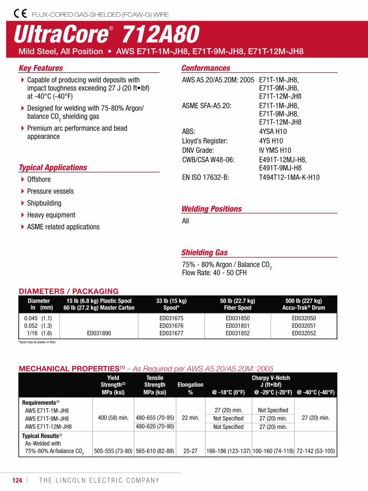
124 ı T H E L I N C O L N E L E C T R I C C O M P A N Y
UltraCore ® 712A80FLUX-CORED GAS-SHIELDED (FCAW-G) WIRE
Welding Positions
Typical Applications
All
Offshore
Pressure vessels
Shipbuilding
Heavy equipment
ASME related applications
Capable of producing weld deposits with impact toughness exceeding 27 J (20 ft•lbf) at -40°C (-40°F)
Designed for welding with 75-80% Argon/ balance CO2 shielding gas
Premium arc performance and bead appearance
Conformances
Shielding Gas75% - 80% Argon / Balance CO2Flow Rate: 40 - 50 CFH
Key FeaturesAWS A5.20/A5.20M: 2005
ASME SFA-A5.20:
ABS:Lloyd’s Register:DNV Grade:CWB/CSA W48-06:
EN ISO 17632-B:
E71T-1M-JH8, E71T-9M-JH8, E71T-12M-JH8E71T-1M-JH8, E71T-9M-JH8, E71T-12M-JH84YSA H104YS H10IV YMS H10E491T-12MJ-H8, E491T-9MJ-H8T494T12-1MA-K-H10
DIAMETERS / PACKAGINGDiameter 15 lb (6.8 kg) Plastic Spool
60 lb (27.2 kg) Master Carton33 lb (15 kg)
Spool*50 lb (22.7 kg)
Fiber Spool500 lb (227 kg)
Accu-Trak® Drumin (mm)
0.0450.0521/16
(1.1)(1.3)(1.6) ED031890
ED031675ED031676ED031677
ED031850ED031851ED031852
ED032050ED032051ED032052
MECHANICAL PROPERTIES(1)
Yield Strength(2)
Tensile Strength Elongation
Charpy V-NotchJ (ft•lbf)
MPa (ksi) MPa (ksi) % @ -18°C (0°F) @ -29°C (-20°F) @ -40°C (-40°F)
Requirements(4)
AWS E71T-1M-JH8AWS E71T-9M-JH8AWS E71T-12M-JH8
400 (58) min. 480-655 (70-95)
22 min.
27 (20) min. Not Specified
27 (20) min.Not Specified 27 (20) min.480-620 (70-90) Not Specified 27 (20) min.
Typical Results(3)
As-Welded with 75%-80% Ar/balance CO2 505-555 (73-80) 565-610 (82-88) 25-27 166-186 (123-137) 100-160 (74-118) 72-142 (53-105)
*Spool may be plastic or fiber.
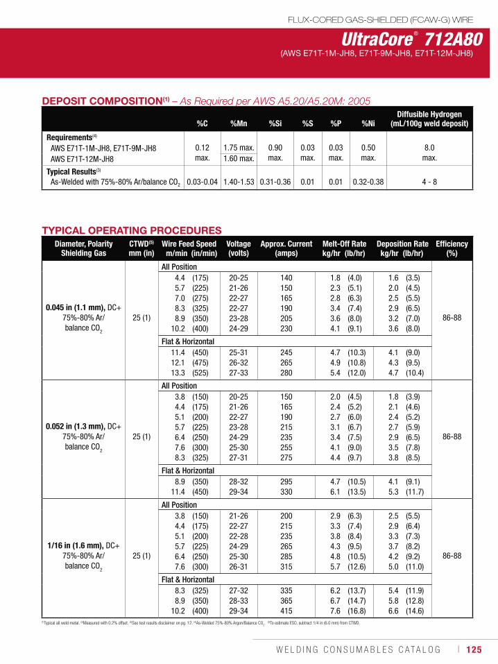
W E L D I N G C O N S U M A B L E S C A T A L O G ı 125
UltraCore ® 712A80FLUX-CORED GAS-SHIELDED (FCAW-G) WIRE
(AWS E71T-1M-JH8, E71T-9M-JH8, E71T-12M-JH8)
DEPOSIT COMPOSITION(1)
%C %Mn %Si %S %P %NiDiffusible Hydrogen
(mL/100g weld deposit)
Requirements(4)
AWS E71T-1M-JH8, E71T-9M-JH8AWS E71T-12M-JH8
0.12 max.
1.75 max. 0.90 max.
0.03 max.
0.03 max.
0.50 max.
8.0 max.1.60 max.
Typical Results(3)
As-Welded with 75%-80% Ar/balance CO2 0.03-0.04 1.40-1.53 0.31-0.36 0.01 0.01 0.32-0.38 4 - 8
TYPICAL OPERATING PROCEDURESDiameter, Polarity
Shielding GasCTWD(5)
mm (in)Wire Feed Speed Voltage
(volts)Approx. Current
(amps)Melt-Off Rate Deposition Rate Efficiency
(%)m/min (in/min) kg/hr (lb/hr) kg/hr (lb/hr)
0.045 in (1.1 mm), DC+75%-80% Ar/ balance CO2
25 (1)
All Position
86-88
4.45.77.08.38.9
10.2
(175)(225)(275)(325)(350)(400)
20-2521-2622-2722-2723-2824-29
140150165190205230
1.82.32.83.43.64.1
(4.0)(5.1)(6.3)(7.4)(8.0)(9.1)
1.62.02.52.93.23.6
(3.5)(4.5)(5.5)(6.5)(7.0)(8.0)
Flat & Horizontal11.412.113.3
(450)(475)(525)
25-3126-3227-33
245265280
4.74.95.4
(10.3)(10.8)(12.0)
4.14.34.7
(9.0)(9.5)(10.4)
0.052 in (1.3 mm), DC+75%-80% Ar/ balance CO
2
25 (1)
All Position
86-88
3.84.45.15.76.47.68.3
(150)(175)(200)(225)(250)(300)(325)
20-2521-2622-2723-2824-2925-3027-31
150165190215235255275
2.02.42.73.13.44.14.4
(4.5)(5.2)(6.0)(6.7)(7.5)(9.0)(9.7)
1.82.12.42.72.93.53.8
(3.9)(4.6)(5.2)(5.9)(6.5)(7.8)(8.5)
Flat & Horizontal8.9
11.4(350)(450)
28-3229-34
295330
4.76.1
(10.5)(13.5)
4.15.3
(9.1)(11.7)
1/16 in (1.6 mm), DC+75%-80% Ar/ balance CO
2
25 (1)
All Position
86-88
3.84.45.15.76.47.6
(150)(175)(200)(225)(250)(300)
21-2622-2722-2824-2925-3026-31
200215235265285315
2.93.33.84.34.85.7
(6.3)(7.4)(8.4)(9.5)(10.5)(12.6)
2.52.93.33.74.25.0
(5.5)(6.4)(7.3)(8.2)(9.2)(11.0)
Flat & Horizontal8.38.9
10.2
(325)(350)(400)
27-3228-3329-34
335365415
6.26.77.6
(13.7)(14.7)(16.8)
5.45.86.6
(11.9)(12.8)(14.6)
(1)Typical all weld metal. (2)Measured with 0.2% offset. (3)See test results disclaimer on pg. 12. (4)As-Welded 75%-80% Argon/Balance CO2. (5)To estimate ESO, subtract 1/4 in (6.0 mm) from CTWD.
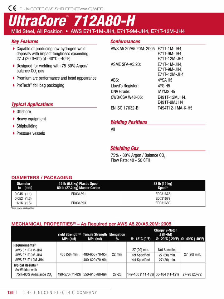
126 ı T H E L I N C O L N E L E C T R I C C O M P A N Y
UltraCore ® 712A80-HFLUX-CORED GAS-SHIELDED (FCAW-G) WIRE
Welding Positions
Typical Applications
All
Offshore
Heavy equipment
Shipbuilding
Pressure vessels
Capable of producing low hydrogen weld deposits with impact toughness exceeding 27 J (20 ft•lbf) at -40°C (-40°F)
Designed for welding with 75-80% Argon/ balance CO2 gas
Premium arc performance and bead appearance
ProTech® foil bag packaging
Conformances
Shielding Gas75% - 80% Argon / Balance CO2Flow Rate: 40 - 50 CFH
Key FeaturesAWS A5.20/A5.20M: 2005
ASME SFA-A5.20:
ABS:Lloyd’s Register:DNV Grade:CWB/CSA W48-06:
EN ISO 17632-B:
E71T-1M-JH4, E71T-9M-JH4, E71T-12M-JH4E71T-1M-JH4, E71T-9M-JH4, E71T-12M-JH44YSA H54YS H5IV YMS H5E491T-12MJ H4, E491T-9MJ H4T494T12-1MA-K-H5
DIAMETERS / PACKAGINGDiameter 15 lb (6.8 kg) Plastic Spool
60 lb (27.2 kg) Master Carton33 lb (15 kg)
Spool*in (mm)
0.0450.0521/16
(1.1)(1.3)(1.6)
ED031891
ED031893
ED031678ED031679ED031680
MECHANICAL PROPERTIES(1) – As Required per AWS A5.20/A5.20M: 2005
Yield Strength(2) Tensile Strength ElongationCharpy V-Notch
J (ft•lbf)MPa (ksi) MPa (ksi) % @ -18°C (0°F) @ -29°C (-20°F) @ -40°C (-40°F)
Requirements(4)
AWS E71T-1M-JH4AWS E71T-9M-JH4AWS E71T-12M-JH4
400 (58) min. 480-655 (70-95)
22 min.
27 (20) min. Not Specified
27 (20) min.Not Specified 27 (20) min.480-620 (70-90) Not Specified 27 (20) min.
Typical Results(3)
As-Welded with 75%-80% Ar/balance CO2 490-570 (71-83) 550-615 (80-89) 27-28 149-180 (111-133) 56-164 (41-121) 27-98 (20-72)
*Spool may be plastic or fiber.
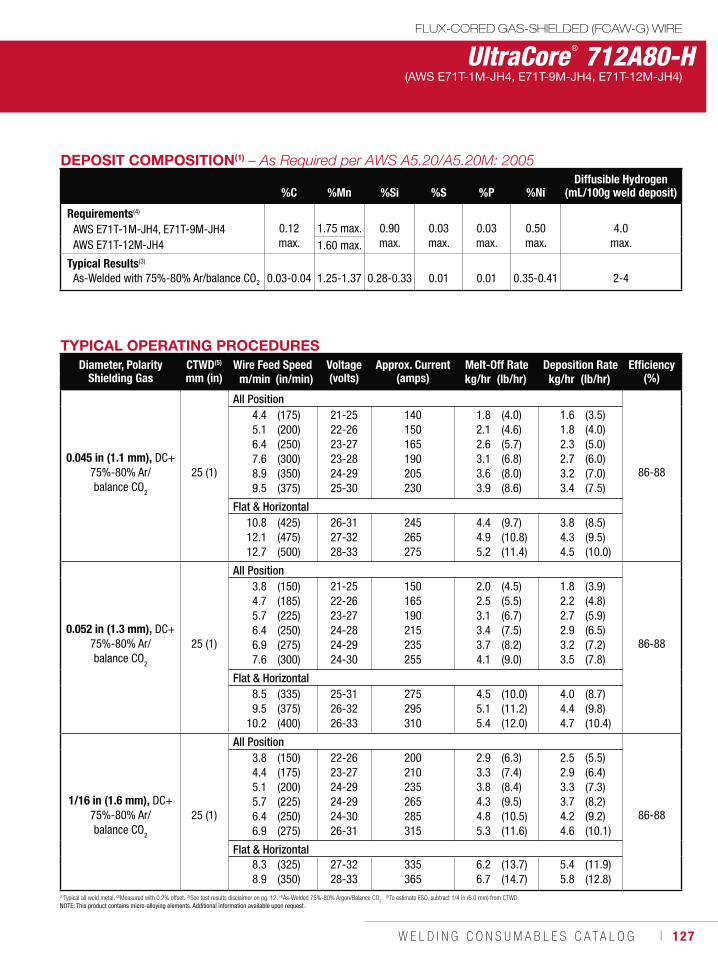
W E L D I N G C O N S U M A B L E S C A T A L O G ı 127
UltraCore ® 712A80-HFLUX-CORED GAS-SHIELDED (FCAW-G) WIRE
(AWS E71T-1M-JH4, E71T-9M-JH4, E71T-12M-JH4)
DEPOSIT COMPOSITION(1)
%C %Mn %Si %S %P %NiDiffusible Hydrogen
(mL/100g weld deposit)
Requirements(4)
AWS E71T-1M-JH4, E71T-9M-JH4AWS E71T-12M-JH4
0.12 max.
1.75 max. 0.90 max.
0.03 max.
0.03 max.
0.50 max.
4.0 max.1.60 max.
Typical Results(3)
As-Welded with 75%-80% Ar/balance CO2 0.03-0.04 1.25-1.37 0.28-0.33 0.01 0.01 0.35-0.41 2-4
TYPICAL OPERATING PROCEDURESDiameter, Polarity
Shielding GasCTWD(5)
mm (in)Wire Feed Speed Voltage
(volts)Approx. Current
(amps)Melt-Off Rate Deposition Rate Efficiency
(%)m/min (in/min) kg/hr (lb/hr) kg/hr (lb/hr)
0.045 in (1.1 mm), DC+75%-80% Ar/ balance CO2
25 (1)
All Position
86-88
4.45.16.47.68.99.5
(175)(200)(250)(300)(350)(375)
21-2522-2623-2723-2824-2925-30
140150165190205230
1.82.12.63.13.63.9
(4.0)(4.6)(5.7)(6.8)(8.0)(8.6)
1.61.82.32.73.23.4
(3.5)(4.0)(5.0)(6.0)(7.0)(7.5)
Flat & Horizontal10.812.112.7
(425)(475)(500)
26-3127-3228-33
245265275
4.44.95.2
(9.7)(10.8)(11.4)
3.84.34.5
(8.5)(9.5)(10.0)
0.052 in (1.3 mm), DC+75%-80% Ar/ balance CO
2
25 (1)
All Position
86-88
3.84.75.76.46.97.6
(150)(185)(225)(250)(275)(300)
21-2522-2623-2724-2824-2924-30
150165190215235255
2.02.53.13.43.74.1
(4.5)(5.5)(6.7)(7.5)(8.2)(9.0)
1.82.22.72.93.23.5
(3.9)(4.8)(5.9)(6.5)(7.2)(7.8)
Flat & Horizontal8.59.5
10.2
(335)(375)(400)
25-3126-3226-33
275295310
4.55.15.4
(10.0)(11.2)(12.0)
4.04.44.7
(8.7)(9.8)(10.4)
1/16 in (1.6 mm), DC+75%-80% Ar/ balance CO
2
25 (1)
All Position
86-88
3.84.45.15.76.46.9
(150)(175)(200)(225)(250)(275)
22-2623-2724-2924-2924-3026-31
200210235265285315
2.93.33.84.34.85.3
(6.3)(7.4)(8.4)(9.5)(10.5)(11.6)
2.52.93.33.74.24.6
(5.5)(6.4)(7.3)(8.2)(9.2)(10.1)
Flat & Horizontal8.38.9
(325)(350)
27-3228-33
335365
6.26.7
(13.7)(14.7)
5.45.8
(11.9)(12.8)
(1)Typical all weld metal. (2)Measured with 0.2% offset. (3)See test results disclaimer on pg. 12. (4)As-Welded 75%-80% Argon/Balance CO2. (5)To estimate ESO, subtract 1/4 in (6.0 mm) from CTWD.
NOTE: This product contains micro-alloying elements. Additional information available upon request.
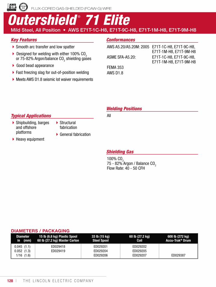
128 ı T H E L I N C O L N E L E C T R I C C O M P A N Y
Outershield ® 71 Elite
Welding PositionsTypical Applications All
Shipbuilding, barges and offshore platforms
Heavy equipment
Structural fabrication
General fabrication
Smooth arc transfer and low spatter
Designed for welding with either 100% CO2 or 75-82% Argon/balance CO2 shielding gases
Good bead appearance
Fast freezing slag for out-of-position welding
Meets AWS D1.8 seismic lot waiver requirements
Conformances
Shielding Gas100% CO275 - 82% Argon / Balance CO2Flow Rate: 40 - 50 CFH
Key FeaturesAWS A5.20/A5.20M: 2005
ASME SFA-A5.20:
FEMA 353AWS D1.8
E71T-1C-H8, E71T-9C-H8, E71T-1M-H8, E71T-9M-H8E71T-1C-H8, E71T-9C-H8, E71T-1M-H8, E71T-9M-H8
DIAMETERS / PACKAGINGDiameter 15 lb (6.8 kg) Plastic Spool
60 lb (27.2 kg) Master Carton33 lb (15 kg)Steel Spool
60 lb (27.2 kg)Coil
600 lb (272 kg)Accu-Trak® Drumin (mm)
0.0450.0521/16
(1.1)(1.3)(1.6)
ED029418 ED029419
ED029201 ED029204 ED029206
ED029202 ED029205 ED029207 ED029387
FLUX-CORED GAS-SHIELDED (FCAW-G) WIREStructural Welding Code Seismic Supplement
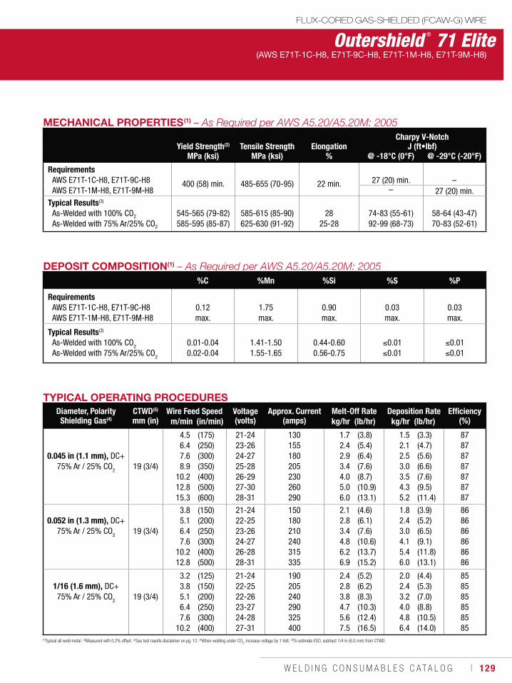
W E L D I N G C O N S U M A B L E S C A T A L O G ı 129
Outershield ® 71 Elite(AWS E71T-1C-H8, E71T-9C-H8, E71T-1M-H8, E71T-9M-H8)
DEPOSIT COMPOSITION(1)
%C %Mn %Si %S %P
RequirementsAWS E71T-1C-H8, E71T-9C-H8AWS E71T-1M-H8, E71T-9M-H8
0.12 max.
1.75 max.
0.90 max.
0.03 max.
0.03 max.
Typical Results(3)
As-Welded with 100% CO2
As-Welded with 75% Ar/25% CO2
0.01-0.040.02-0.04
1.41-1.50 1.55-1.65
0.44-0.60 0.56-0.75
0.01 0.01
0.01 0.01
(1)Typical all weld metal. (2)Measured with 0.2% offset. (3)See test results disclaimer on pg. 12. (4)When welding under CO2, increase voltage by 1 Volt. (5)To estimate ESO, subtract 1/4 in (6.0 mm) from CTWD.
TYPICAL OPERATING PROCEDURESDiameter, PolarityShielding Gas(4)
CTWD(5)
mm (in)Wire Feed Speed Voltage
(volts)Approx. Current
(amps)Melt-Off Rate Deposition Rate Efficiency
(%)m/min (in/min) kg/hr (lb/hr) kg/hr (lb/hr)
0.045 in (1.1 mm), DC+75% Ar / 25% CO2 19 (3/4)
4.5 6.4 7.6 8.9
10.2 12.8 15.3
(175)(250)(300)(350)(400)(500)(600)
21-24 23-26 24-27 25-28 26-29 27-30 28-31
130 155 180 205 230 260 290
1.7 2.42.93.4 4.0 5.0 6.0
(3.8)(5.4)(6.4)(7.6)(8.7)(10.9)(13.1)
1.52.1 2.5 3.0 3.5 4.3 5.2
(3.3)(4.7)(5.6)(6.6)(7.6)(9.5)(11.4)
87 87 87 87 87 87 87
0.052 in (1.3 mm), DC+ 75% Ar / 25% CO
2 19 (3/4)
3.8 5.1 6.4 7.6
10.2 12.8
(150)(200)(250)(300)(400)(500)
21-24 22-25 23-26 24-27 26-28 28-31
150 180 210 240 315 335
2.1 2.83.4 4.8 6.2 6.9
(4.6)(6.1)(7.6)(10.6)(13.7)(15.2)
1.8 2.4 3.0 4.1 5.4 6.0
(3.9)(5.2)(6.5)(9.1)(11.8)(13.1)
86 86 86 86 86 86
1/16 (1.6 mm), DC+ 75% Ar / 25% CO
2 19 (3/4)
3.23.85.1 6.4 7.6
10.2
(125)(150)(200)(250)(300)(400)
21-24 22-25 22-26 23-27 24-28 27-31
190 205 240 290 325 400
2.42.8 3.84.7 5.6 7.5
(5.2)(6.2)(8.3)(10.3)(12.4)(16.5)
2.0 2.43.2 4.0 4.86.4
(4.4)(5.3)(7.0)(8.8)(10.5)(14.0)
85 85 85 85 85 85
FLUX-CORED GAS-SHIELDED (FCAW-G) WIRE
MECHANICAL PROPERTIES(1)
Yield Strength(2) Tensile Strength ElongationCharpy V-Notch
J (ft•lbf)MPa (ksi) MPa (ksi) % @ -18°C (0°F) @ -29°C (-20°F)
RequirementsAWS E71T-1C-H8, E71T-9C-H8AWS E71T-1M-H8, E71T-9M-H8
400 (58) min.
485-655 (70-95)
22 min.
27 (20) min.
–
– 27 (20) min.Typical Results(3)
As-Welded with 100% CO2
As-Welded with 75% Ar/25% CO2
545-565 (79-82)585-595 (85-87)
585-615 (85-90)625-630 (91-92)
2825-28
74-83 (55-61)92-99 (68-73)
58-64 (43-47)70-83 (52-61)
130 ı T H E L I N C O L N E L E C T R I C C O M P A N Y
Outershield ® 71 SupremeFLUX-CORED GAS-SHIELDED (FCAW-G) WIRE
Welding Positions
Typical Applications
All
Mining
Offshore
Bridge fabrication
High strength fabrication
Structural steel
Designed to be used with either 100% CO2 or 75% Argon/25% CO2 gas
Smooth, consistent arc performance
The finished weld exhibits an extremely smooth bead appearance, even on out-of-position welds
Conformances
Shielding Gas75% Argon / 25% CO2100% CO2Flow Rate: 40 - 50 CFH
Key FeaturesAWS A5.20/A5.20M: 2005
CWB/CSA W48-06:
E491T-9C-H8, E491T-9M-H8E491T-9-H8, E491T-9M-H8
NoteThis product is only sold in Canada.
This product contains micro-alloying elements. Additional information available upon request.
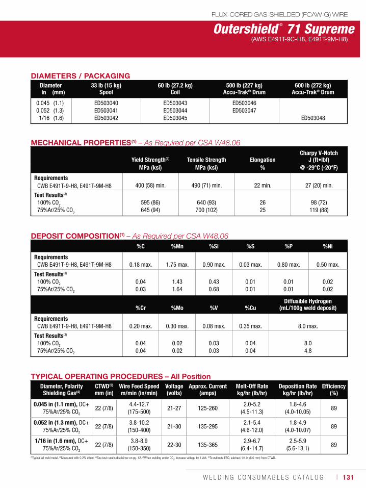
W E L D I N G C O N S U M A B L E S C A T A L O G ı 131
Outershield ® 71 SupremeFLUX-CORED GAS-SHIELDED (FCAW-G) WIRE
(AWS E491T-9C-H8, E491T-9M-H8)
TYPICAL OPERATING PROCEDURES – All PositionDiameter, PolarityShielding Gas(4)
CTWD(5)
mm (in)Wire Feed Speed Voltage
(volts)Approx. Current
(amps)Melt-Off Rate Deposition Rate Efficiency
(%)m/min (in/min) kg/hr (lb/hr) kg/hr (lb/hr)
0.045 in (1.1 mm), DC+75%Ar/25% CO2
22 (7/8)4.4-12.7
(175-500)21-27 125-260
2.0-5.2 (4.5-11.3)
1.8-4.6 (4.0-10.05)
89
0.052 in (1.3 mm), DC+75%Ar/25% CO2
22 (7/8)3.8-10.2
(150-400)21-30 135-295
2.1-5.4 (4.6-12.0)
1.8-4.9 (4.0-10.07)
89
1/16 in (1.6 mm), DC+75%Ar/25% CO2
22 (7/8)3.8-8.9
(150-350)22-30 135-365
2.9-6.7 (6.4-14.7)
2.5-5.9 (5.6-13.1)
89
(1)Typical all weld metal. (2)Measured with 0.2% offset. (3)See test results disclaimer on pg. 12. (4)When welding under CO2, increase voltage by 1 Volt. (5)To estimate ESO, subtract 1/4 in (6.0 mm) from CTWD.
MECHANICAL PROPERTIES(1)
Yield Strength(2) Tensile Strength ElongationCharpy V-Notch
J (ft•lbf)MPa (ksi) MPa (ksi) % @ -29°C (-20°F)
RequirementsCWB E491T-9-H8, E491T-9M-H8
400 (58) min. 490 (71) min.
22 min.
27 (20) min.
Test Results(3)
100% CO2
75%Ar/25% CO2
595 (86)645 (94)
640 (93) 700 (102)
2625
98 (72)119 (88)
DEPOSIT COMPOSITION(1)
%C %Mn %Si %S %P %Ni
RequirementsCWB E491T-9-H8, E491T-9M-H8 0.18 max. 1.75 max. 0.90 max. 0.03 max. 0.80 max. 0.50 max.
Test Results(3)
100% CO2
75%Ar/25% CO2
0.040.03
1.431.64
0.430.68
0.010.01
0.010.01
0.020.02
%Cr %Mo %V %CuDiffusible Hydrogen
(mL/100g weld deposit)
RequirementsCWB E491T-9-H8, E491T-9M-H8 0.20 max. 0.30 max. 0.08 max. 0.35 max. 8.0 max.
Test Results(3)
100% CO2
75%Ar/25% CO2
0.040.04
0.020.02
0.030.03
0.040.04
8.04.8
DIAMETERS / PACKAGINGDiameter 33 lb (15 kg)
Spool60 lb (27.2 kg)
Coil500 lb (227 kg)
Accu-Trak® Drum600 lb (272 kg)
Accu-Trak® Drumin (mm)
0.0450.0521/16
(1.1)(1.3)(1.6)
ED503040ED503041ED503042
ED503043ED503044ED503045
ED503046ED503047
ED503048
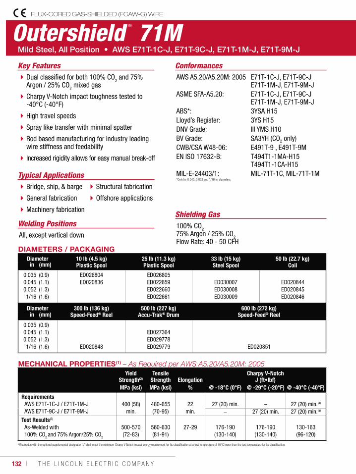
132 ı T H E L I N C O L N E L E C T R I C C O M P A N Y
Outershield ® 71MFLUX-CORED GAS-SHIELDED (FCAW-G) WIRE
Welding Positions
Typical Applications
All, except vertical down
Bridge, ship, & barge
General fabrication
Machinery fabrication
Structural fabrication
Offshore applications
Dual classified for both 100% CO2 and 75% Argon / 25% CO2 mixed gas
Charpy V-Notch impact toughness tested to -40°C (-40°F)
High travel speeds
Spray like transfer with minimal spatter
Rod based manufacturing for industry leading wire stiffness and feedability
Increased rigidity allows for easy manual break-off
Conformances
Shielding Gas100% CO275% Argon / 25% CO2Flow Rate: 40 - 50 CFH
Key FeaturesAWS A5.20/A5.20M: 2005
ASME SFA-A5.20:
ABS*:Lloyd’s Register:DNV Grade:BV Grade:CWB/CSA W48-06:EN ISO 17632-B:
MIL-E-24403/1:
E71T-1C-J, E71T-9C-J E71T-1M-J, E71T-9M-JE71T-1C-J, E71T-9C-J E71T-1M-J, E71T-9M-J3YSA H153YS H15III YMS H10SA3YH (CO2 only)E491T-9 , E491T-9M T494T1-1MA-H15 T494T1-1CA-H15MIL-71T-1C, MIL-71T-1M
DIAMETERS / PACKAGINGDiameter 10 lb (4.5 kg)
Plastic Spool25 lb (11.3 kg)Plastic Spool
33 lb (15 kg)Steel Spool
50 lb (22.7 kg)Coilin (mm)
0.0350.0450.0521/16
(0.9)(1.1)(1.3)(1.6)
ED026804 ED020836
ED026805 ED022659 ED022660 ED022661
ED030007 ED030008 ED030009
ED020844 ED020845 ED020846
Diameter 300 lb (136 kg)Speed-Feed® Reel
500 lb (227 kg)Accu-Trak® Drum
600 lb (272 kg)Speed-Feed® Reelin (mm)
0.0350.0450.0521/16
(0.9)(1.1)(1.3)(1.6) ED020848
ED027364 ED029778 ED029779 ED020851
(a)Electrodes with the optional supplemental designator “J” shall meet the minimum Charpy V-Notch impact energy requirement for its classification at a test temperature of 10°C lower than the test temperature for its classification.
*Only for 0.045, 0.052 and 1/16 in. diameters
MECHANICAL PROPERTIES(1)
Yield Strength(2)
Tensile Strength Elongation
Charpy V-NotchJ (ft•lbf)
MPa (ksi) MPa (ksi) % @ -18°C (0°F) @ -29°C (-20°F) @ -40°C (-40°F)
RequirementsAWS E71T-1C-J / E71T-1M-J AWS E71T-9C-J / E71T-9M-J
400 (58)
min.
480-655 (70-95)
22
min.
27 (20) min.
–
27 (20) min.(a)
– 27 (20) min. 27 (20) min.(a)
Test Results(3)
As-Welded with 100% CO2 and 75% Argon/25% CO2
500-570 (72-83)
560-630 (81-91)
27-29 176-190 (130-140)
176-190 (130-140)
130-163 (96-120)
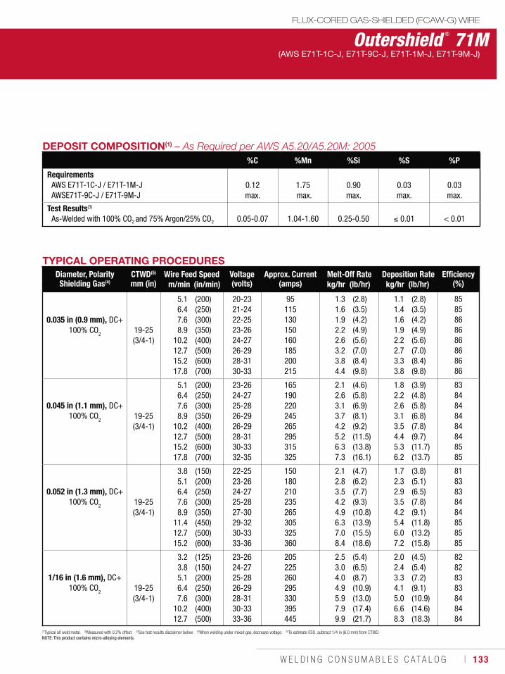
W E L D I N G C O N S U M A B L E S C A T A L O G ı 133
Outershield ® 71MFLUX-CORED GAS-SHIELDED (FCAW-G) WIRE
(AWS E71T-1C-J, E71T-9C-J, E71T-1M-J, E71T-9M-J)
(1)Typical all weld metal. (2)Measured with 0.2% offset. (3)See test results disclaimer below. (4)When welding under mixed gas, decrease voltage. (5)To estimate ESO, subtract 1/4 in (6.0 mm) from CTWD.NOTE: This product contains micro-alloying elements.
DEPOSIT COMPOSITION(1)
%C %Mn %Si %S %P
RequirementsAWS E71T-1C-J / E71T-1M-JAWSE71T-9C-J / E71T-9M-J
0.12 max.
1.75 max.
0.90 max.
0.03 max.
0.03 max.
Test Results(3)
As-Welded with 100% CO2 and 75% Argon/25% CO2 0.05-0.07 1.04-1.60 0.25-0.50 0.01 < 0.01
TYPICAL OPERATING PROCEDURESDiameter, PolarityShielding Gas(4)
CTWD(5)
mm (in)Wire Feed Speed Voltage
(volts)Approx. Current
(amps)Melt-Off Rate Deposition Rate Efficiency
(%)m/min (in/min) kg/hr (lb/hr) kg/hr (lb/hr)
0.035 in (0.9 mm), DC+100% CO2 19-25
(3/4-1)
5.16.47.68.9
10.212.715.217.8
(200)(250)(300)(350)(400)(500)(600)(700)
20-2321-2422-2523-2624-2726-2928-3130-33
95115130150160185200215
1.31.61.92.22.63.23.84.4
(2.8)(3.5)(4.2)(4.9)(5.6)(7.0)(8.4)(9.8)
1.11.41.61.92.22.73.33.8
(2.8)(3.5)(4.2)(4.9)(5.6)(7.0)(8.4)(9.8)
8585868686868686
0.045 in (1.1 mm), DC+ 100% CO
2 19-25 (3/4-1)
5.16.47.68.9
10.212.715.217.8
(200)(250)(300)(350)(400)(500)(600)(700)
23-2624-2725-2826-2926-2928-3130-3332-35
165190220245265295315325
2.12.63.13.74.25.26.37.3
(4.6)(5.8)(6.9)(8.1)(9.2)(11.5)(13.8)(16.1)
1.82.22.63.13.54.45.36.2
(3.9)(4.8)(5.8)(6.8)(7.8)(9.7)(11.7)(13.7)
8384848484848585
0.052 in (1.3 mm), DC+ 100% CO
2 19-25 (3/4-1)
3.85.16.47.68.9
11.412.715.2
(150)(200)(250)(300)(350)(450)(500)(600)
22-2523-2624-2725-2827-3029-3230-3333-36
150180210235265305325360
2.12.83.54.24.96.37.08.4
(4.7)(6.2)(7.7)(9.3)(10.8)(13.9)(15.5)(18.6)
1.72.32.93.54.25.46.07.2
(3.8)(5.1)(6.5)(7.8)(9.1)(11.8)(13.2)(15.8)
8183838484858585
1/16 in (1.6 mm), DC+ 100% CO
2 19-25 (3/4-1)
3.23.85.16.47.6
10.212.7
(125)(150)(200)(250)(300)(400)(500)
23-2624-2725-2826-2928-3130-3333-36
205225260295330395445
2.53.04.04.95.97.99.9
(5.4)(6.5)(8.7)(10.9)(13.0)(17.4)(21.7)
2.02.43.34.15.06.68.3
(4.5)(5.4)(7.2)(9.1)(10.9)(14.6)(18.3)
82828383848484
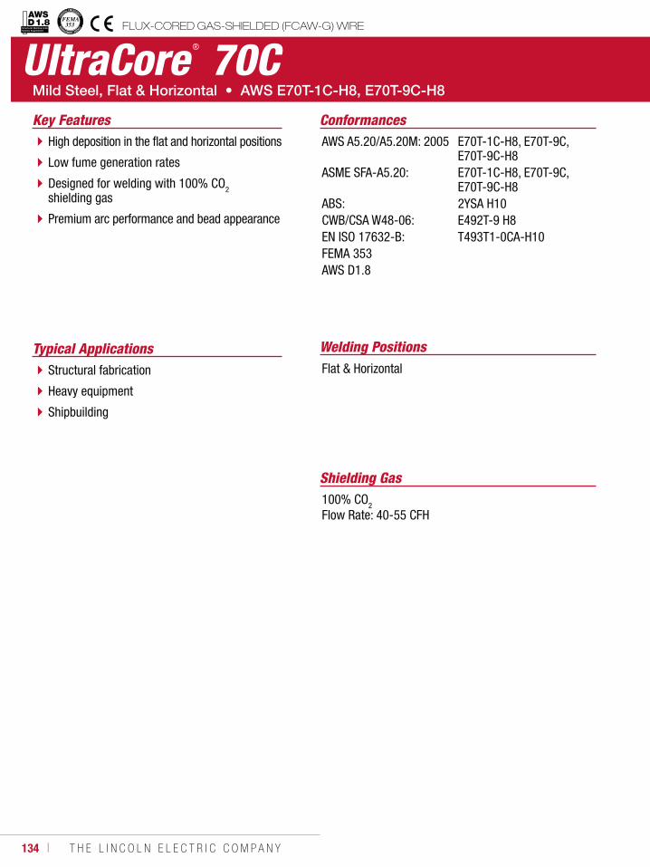
134 ı T H E L I N C O L N E L E C T R I C C O M P A N Y
UltraCore ® 70C
Welding PositionsTypical ApplicationsFlat & HorizontalStructural fabrication
Heavy equipment
Shipbuilding
High deposition in the flat and horizontal positions
Low fume generation rates
Designed for welding with 100% CO2 shielding gas
Premium arc performance and bead appearance
Conformances
Shielding Gas100% CO2
Flow Rate: 40-55 CFH
Key FeaturesAWS A5.20/A5.20M: 2005
ASME SFA-A5.20:
ABS:CWB/CSA W48-06:EN ISO 17632-B:FEMA 353AWS D1.8
E70T-1C-H8, E70T-9C, E70T-9C-H8E70T-1C-H8, E70T-9C, E70T-9C-H82YSA H10E492T-9 H8T493T1-0CA-H10
FLUX-CORED GAS-SHIELDED (FCAW-G) WIREStructural Welding Code Seismic Supplement
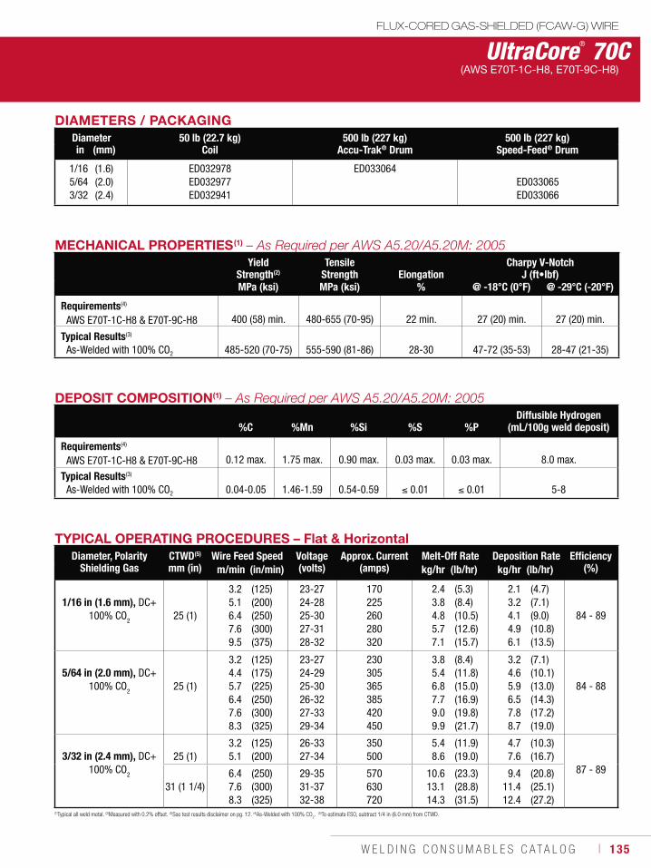
W E L D I N G C O N S U M A B L E S C A T A L O G ı 135
DEPOSIT COMPOSITION(1)
%C %Mn %Si %S %PDiffusible Hydrogen
(mL/100g weld deposit)
Requirements(4)
AWS E70T-1C-H8 & E70T-9C-H8 0.12 max. 1.75 max. 0.90 max. 0.03 max. 0.03 max. 8.0 max.
Typical Results(3)
As-Welded with 100% CO2 0.04-0.05 1.46-1.59 0.54-0.59 0.01 0.01 5-8
MECHANICAL PROPERTIES(1)
Yield Strength(2)
Tensile Strength Elongation
Charpy V-NotchJ (ft•lbf)
MPa (ksi) MPa (ksi) % @ -18°C (0°F) @ -29°C (-20°F)
Requirements(4)
AWS E70T-1C-H8 & E70T-9C-H8
400 (58) min. 480-655 (70-95)
22 min.
27 (20) min. 27 (20) min.
Typical Results(3)
As-Welded with 100% CO2 485-520 (70-75) 555-590 (81-86) 28-30 47-72 (35-53) 28-47 (21-35)
TYPICAL OPERATING PROCEDURES – Flat & HorizontalDiameter, Polarity
Shielding GasCTWD(5)
mm (in)Wire Feed Speed Voltage
(volts)Approx. Current
(amps)Melt-Off Rate Deposition Rate Efficiency
(%)m/min (in/min) kg/hr (lb/hr) kg/hr (lb/hr)
1/16 in (1.6 mm), DC+100% CO2 25 (1)
3.25.16.47.69.5
(125)(200)(250)(300)(375)
23-2724-2825-3027-3128-32
170225260280320
2.43.84.85.77.1
(5.3)(8.4)(10.5)(12.6)(15.7)
2.13.24.14.96.1
(4.7)(7.1)(9.0)(10.8)(13.5)
84 - 89
5/64 in (2.0 mm), DC+100% CO
2 25 (1)
3.24.45.76.47.68.3
(125)(175)(225)(250)(300)(325)
23-2724-2925-3026-3227-3329-34
230305365385420450
3.85.46.87.79.09.9
(8.4)(11.8)(15.0)(16.9)(19.8)(21.7)
3.24.65.96.57.88.7
(7.1)(10.1)(13.0)(14.3)(17.2)(19.0)
84 - 88
3/32 in (2.4 mm), DC+100% CO
2
25 (1)3.25.1
(125)(200)
26-3327-34
350500
5.48.6
(11.9)(19.0)
4.77.6
(10.3)(16.7)
87 - 89
31 (1 1/4)6.47.68.3
(250)(300)(325)
29-3531-3732-38
570630720
10.613.114.3
(23.3)(28.8)(31.5)
9.411.412.4
(20.8)(25.1)(27.2)
(1)Typical all weld metal. (2)Measured with 0.2% offset. (3)See test results disclaimer on pg. 12. (4)As-Welded with 100% CO2. (5)To estimate ESO, subtract 1/4 in (6.0 mm) from CTWD.
UltraCore® 70C(AWS E70T-1C-H8, E70T-9C-H8)
FLUX-CORED GAS-SHIELDED (FCAW-G) WIRE
DIAMETERS / PACKAGINGDiameter 50 lb (22.7 kg)
Coil500 lb (227 kg)
Accu-Trak® Drum500 lb (227 kg)
Speed-Feed® Drumin (mm)
1/165/643/32
(1.6)(2.0)(2.4)
ED032978ED032977ED032941
ED033064ED033065ED033066
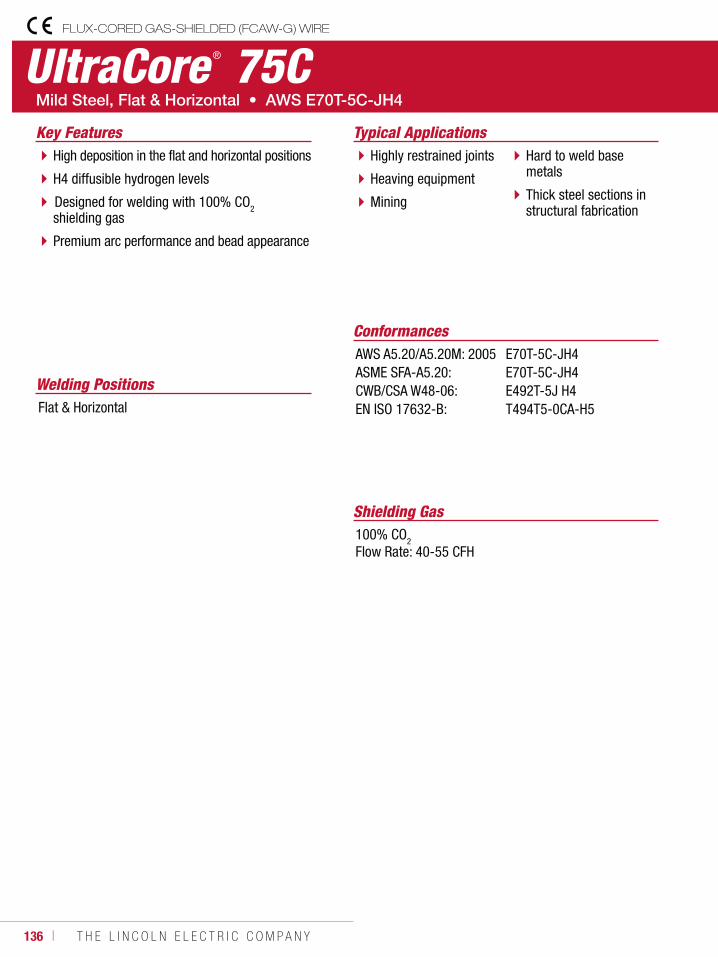
136 ı T H E L I N C O L N E L E C T R I C C O M P A N Y
UltraCore ® 75CFLUX-CORED GAS-SHIELDED (FCAW-G) WIRE
Welding Positions
Typical Applications
Flat & Horizontal
Highly restrained joints
Heaving equipment
Mining
Hard to weld base metals
Thick steel sections in structural fabrication
High deposition in the flat and horizontal positions
H4 diffusible hydrogen levels
Designed for welding with 100% CO2 shielding gas
Premium arc performance and bead appearance
Conformances
Shielding Gas100% CO2
Flow Rate: 40-55 CFH
Key Features
AWS A5.20/A5.20M: 2005ASME SFA-A5.20:CWB/CSA W48-06:EN ISO 17632-B:
E70T-5C-JH4E70T-5C-JH4E492T-5J H4T494T5-0CA-H5
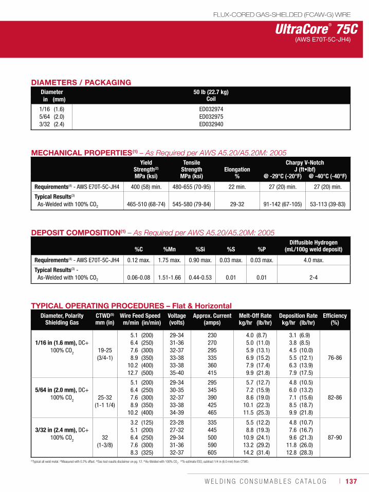
W E L D I N G C O N S U M A B L E S C A T A L O G ı 137
UltraCore ® 75CFLUX-CORED GAS-SHIELDED (FCAW-G) WIRE
(AWS E70T-5C-JH4)
DEPOSIT COMPOSITION(1)
%C %Mn %Si %S %PDiffusible Hydrogen
(mL/100g weld deposit)
Requirements(4) - AWS E70T-5C-JH4 0.12 max. 1.75 max. 0.90 max. 0.03 max. 0.03 max. 4.0 max.
Typical Results(3) - As-Welded with 100% CO2 0.06-0.08 1.51-1.66 0.44-0.53 0.01 0.01 2-4
TYPICAL OPERATING PROCEDURES – Flat & HorizontalDiameter, Polarity
Shielding GasCTWD(5)
mm (in)Wire Feed Speed Voltage
(volts)Approx. Current
(amps)Melt-Off Rate Deposition Rate Efficiency
(%)m/min (in/min) kg/hr (lb/hr) kg/hr (lb/hr)
1/16 in (1.6 mm), DC+100% CO2
19-25(3/4-1)
5.16.47.68.9
10.212.7
(200)(250)(300)(350)(400)(500)
29-3431-3632-3733-3833-3835-40
230270295335360415
4.05.05.96.97.99.9
(8.7)(11.0)(13.1)(15.2)(17.4)(21.8)
3.13.84.55.56.37.9
(6.9)(8.5)(10.0)(12.1)(13.9)(17.5)
76-86
5/64 in (2.0 mm), DC+100% CO
2 25-32 (1-1 1/4)
5.16.47.68.9
10.2
(200)(250)(300)(350)(400)
29-3430-3532-3733-3834-39
295345390425465
5.77.28.6
10.111.5
(12.7)(15.9)(19.0)(22.3)(25.3)
4.86.07.18.59.9
(10.5)(13.2)(15.6)(18.7)(21.8)
82-86
3/32 in (2.4 mm), DC+100% CO
2 32 (1-3/8)
3.25.16.47.68.3
(125)(200)(250)(300)(325)
23-2827-3229-3431-3632-37
335445500590605
5.58.8
10.913.214.2
(12.2)(19.3)(24.1)(29.2)(31.4)
4.87.69.6
11.812.8
(10.7)(16.7)(21.3)(26.0)(28.3)
87-90
MECHANICAL PROPERTIES(1)
Yield Strength(2)
Tensile Strength Elongation
Charpy V-NotchJ (ft•lbf)
MPa (ksi) MPa (ksi) % @ -29°C (-20°F) @ -40°C (-40°F)
Requirements(4) - AWS E70T-5C-JH4 400 (58) min. 480-655 (70-95) 22 min. 27 (20) min. 27 (20) min.
Typical Results(3)
As-Welded with 100% CO2 465-510 (68-74) 545-580 (79-84) 29-32 91-142 (67-105) 53-113 (39-83)
(1)Typical all weld metal. (2)Measured with 0.2% offset. (3)See test results disclaimer on pg. 12. (4)As-Welded with 100% CO2. (5)To estimate ESO, subtract 1/4 in (6.0 mm) from CTWD.
DIAMETERS / PACKAGINGDiameter 50 lb (22.7 kg)
Coil in (mm)
1/165/643/32
(1.6)(2.0)(2.4)
ED032974ED032975ED032940
138 ı T H E L I N C O L N E L E C T R I C C O M P A N Y
Outershield ® 70FLUX-CORED GAS-SHIELDED (FCAW-G) WIRE
Welding Positions
Typical Applications
Flat & Horizontal
Structural fabrication
Barge fabrication
Heavy fabrication
Construction equipment
High deposition in the flat and horizontal positions
Designed for welding with 100% CO2 shielding gas
Excellent bead wetting and low spatter
Tolerates mild levels of surface contaminants
Stiff wire for easy breaking
Conformances
Shielding Gas100% CO2Flow Rate: 40-50 CFH
Key FeaturesAWS A5.20/A5.20M: 2005
ASME SFA-A5.20:
ABS:DNV Grade:CWB/CSA W48-06:TUV:
MIL-E-24403/1:
E70T-1C-H16, E70T-9C-H16E70T-1C-H16, E70T-9C-H162YSAII YMS H15E492T-9 H16EN 758 T 46 0 R C3 / M3 H10MIL-70T-1C
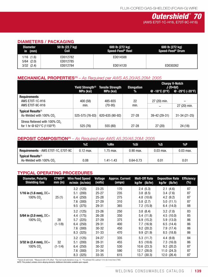
W E L D I N G C O N S U M A B L E S C A T A L O G ı 139
Outershield ® 70FLUX-CORED GAS-SHIELDED (FCAW-G) WIRE
(AWS E70T-1C-H16, E70T-9C-H16)
DEPOSIT COMPOSITION(1)
%C %Mn %Si %S %P
Requirements - AWS E70T-1C, E70T-9C 0.12 max. 1.75 max. 0.90 max. 0.03 max. 0.03 max.
Typical Results(3)
As-Welded with 100% CO2 0.08 1.41-1.43 0.64-0.73 0.01 0.01
MECHANICAL PROPERTIES(1)
Yield Strength(2) Tensile Strength ElongationCharpy V-Notch
J (ft•lbf)MPa (ksi) MPa (ksi) % @ -18°C (0°F) @ -29°C (-20°F)
RequirementsAWS E70T-1C-H16AWS E70T-9C-H16
400 (58)
min.
485-655 (70-95)
22
min.
27 (20) min.
–
– 27 (20) min.
Typical Results(3)
As-Welded with 100% CO2 525-575 (76-83) 620-635 (90-92) 27-28 39-42 (29-31) 31-34 (21-25)
Stress Relieved with 100% CO2
for 1 hr @ 621°C (1150°F) 525 (76) 555 (80) 27-28 27 (20) 24 (18)
TYPICAL OPERATING PROCEDURESDiameter, Polarity
Shielding GasCTWD(5)
mm (in)Wire Feed Speed Voltage
(volts)Approx. Current
(amps)Melt-Off Rate Deposition Rate Efficiency
(%)m/min (in/min) kg/hr (lb/hr) kg/hr (lb/hr)
1/16 in (1.6 mm), DC+100% CO2 25 (1)
3.25.16.47.69.5
(125)(200)(250)(300)(375)
23-25 25-27 25-28 27-29 29-31
170 235 275 310 365
2.43.84.85.8 7.2
(5.3) (8.5)(10.6)(2.7)(15.9)
2.13.44.25.06.4
(4.6)(7.6)(9.2)(11.1) (14.0)
87 87 878788
5/64 in (2.0 mm), DC+100% CO
2 28 (1-1/8)
3.24.45.76.4 7.6 8.3
(125)(175)(225)(250)(300)(325)
23-26 26-28 27-29 29-31 30-32 31-33
250 350 375 400 450 470
3.85.46.97.7 9.2 9.9
(8.4)(11.8)(15.2)(16.9)(20.2)(21.9)
3.24.55.96.5 7.98.5
(7.0)(10.0)(13.0)(14.4)(17.4)(18.8)
83 85 86 86 86 86
3/32 in (2.4 mm), DC+100% CO
2
32 (1-1/4)
3.2 5.1 6.4 7.6 8.3
(125)(200)(250)(300)(325)
24-27 28-31 30-32 31-34 33-35
335 455 530 590 615
5.38.5
10.612.7 13.7
(11.7)(18.6)(23.3)(28.0)(30.3)
4.47.39.2
11.012.0
(9.8)(16.0)(20.2)(24.3)(26.4)
84 86 87 87 87
(1)Typical all weld metal. (2)Measured with 0.2% offset. (3)See test results disclaimer on pg. 12. (4)To estimate ESO, subtract 1/4 in (6.0 mm) from CTWD.NOTE: This product contains micro-alloying elements. Additional information available upon request.
DIAMETERS / PACKAGINGDiameter 50 lb (22.7 kg)
Coil600 lb (272 kg)
Speed-Feed® Reel600 lb (272 kg)
Speed-Feed® Drumin (mm)
1/165/643/32
(1.6)(2.0)(2.4)
ED012782 ED012785 ED012784
ED014588
ED014120 ED030262
140 ı T H E L I N C O L N E L E C T R I C C O M P A N Y
Outershield ® XLH-70
Welding Positions
Typical Applications
Flat & Horizontal
Structural fabrication
General fabrication
Machinery fabrication
Heavy equipment
Seismic applications
Meets AWS D1.8 seismic lot waiver requirements for demand critical welds.
H8 diffusible hydrogen levels - controlled for high resistance to hydrogen induced cracking.
High deposition rates and excellent fast follow characteristics.
Stiff wire enables feeding over long distances.
Tolerates mild levels of surface contaminants.
Designed for welding with CO2 shielding gas.
Conformances
Shielding Gas100% CO2Flow Rate: 40-50 CFH
Key FeaturesAWS A5.20/A5.20M: 2005ASME SFA-5.20:ABS:FEMA 353 AWS D1.8
E70T-1C-H8, E70T-9C-H8E70T-1C-H8, E70T-9C-H83YSA-H5
FLUX-CORED GAS-SHIELDED (FCAW-G) WIREStructural Welding Code Seismic Supplement
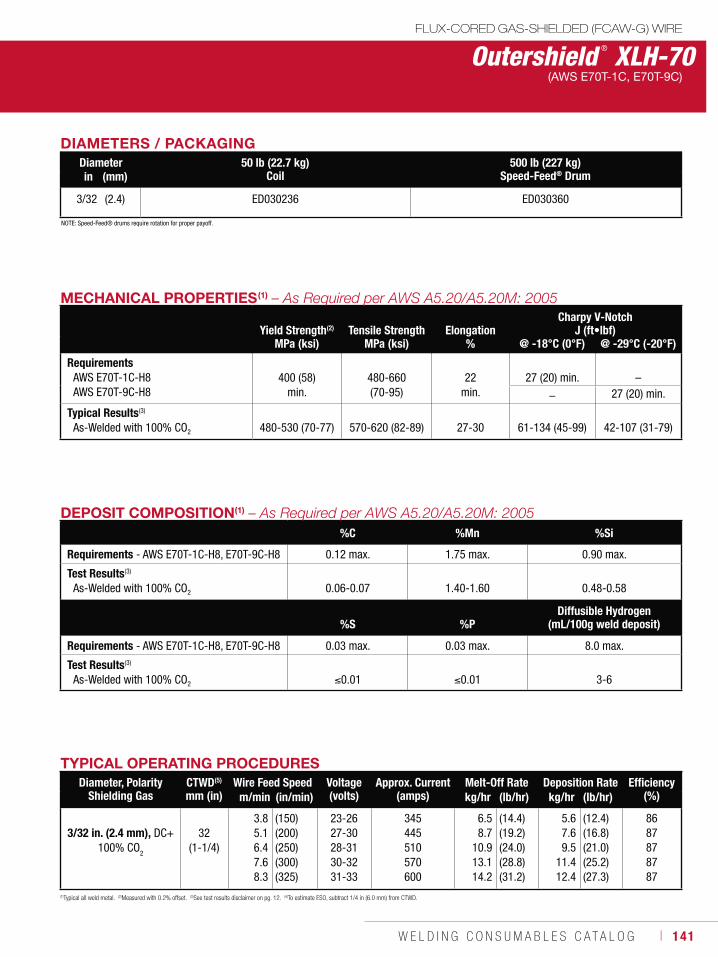
W E L D I N G C O N S U M A B L E S C A T A L O G ı 141
Outershield ® XLH-70(AWS E70T-1C, E70T-9C)
DEPOSIT COMPOSITION(1)
%C %Mn %Si
Requirements - AWS E70T-1C-H8, E70T-9C-H8 0.12 max. 1.75 max. 0.90 max.
Test Results(3)
As-Welded with 100% CO2 0.06-0.07 1.40-1.60 0.48-0.58
%S %PDiffusible Hydrogen
(mL/100g weld deposit)
Requirements - AWS E70T-1C-H8, E70T-9C-H8 0.03 max. 0.03 max. 8.0 max.
Test Results(3)
As-Welded with 100% CO2 0.01 0.01 3-6
MECHANICAL PROPERTIES(1)
Yield Strength(2) Tensile Strength ElongationCharpy V-Notch
J (ft•lbf)MPa (ksi) MPa (ksi) % @ -18°C (0°F) @ -29°C (-20°F)
RequirementsAWS E70T-1C-H8AWS E70T-9C-H8
400 (58)
min.
480-660 (70-95)
22
min.
27 (20) min.
–
– 27 (20) min.
Typical Results(3)
As-Welded with 100% CO2 480-530 (70-77) 570-620 (82-89) 27-30 61-134 (45-99) 42-107 (31-79)
TYPICAL OPERATING PROCEDURESDiameter, Polarity
Shielding GasCTWD(5)
mm (in)Wire Feed Speed Voltage
(volts)Approx. Current
(amps)Melt-Off Rate Deposition Rate Efficiency
(%)m/min (in/min) kg/hr (lb/hr) kg/hr (lb/hr)
3/32 in. (2.4 mm), DC+100% CO2
32 (1-1/4)
3.85.16.47.68.3
(150)(200)(250)(300)(325)
23-2627-3028-3130-3231-33
345445510570600
6.58.7
10.913.114.2
(14.4)(19.2)(24.0)(28.8)(31.2)
5.67.69.5
11.412.4
(12.4)(16.8)(21.0)(25.2)(27.3)
8687878787
(1)Typical all weld metal. (2)Measured with 0.2% offset. (3)See test results disclaimer on pg. 12. (4)To estimate ESO, subtract 1/4 in (6.0 mm) from CTWD.
FLUX-CORED GAS-SHIELDED (FCAW-G) WIRE
DIAMETERS / PACKAGINGDiameter 50 lb (22.7 kg)
Coil 500 lb (227 kg)
Speed-Feed® Drumin (mm)
3/32 (2.4) ED030236 ED030360
NOTE: Speed-Feed® drums require rotation for proper payoff.
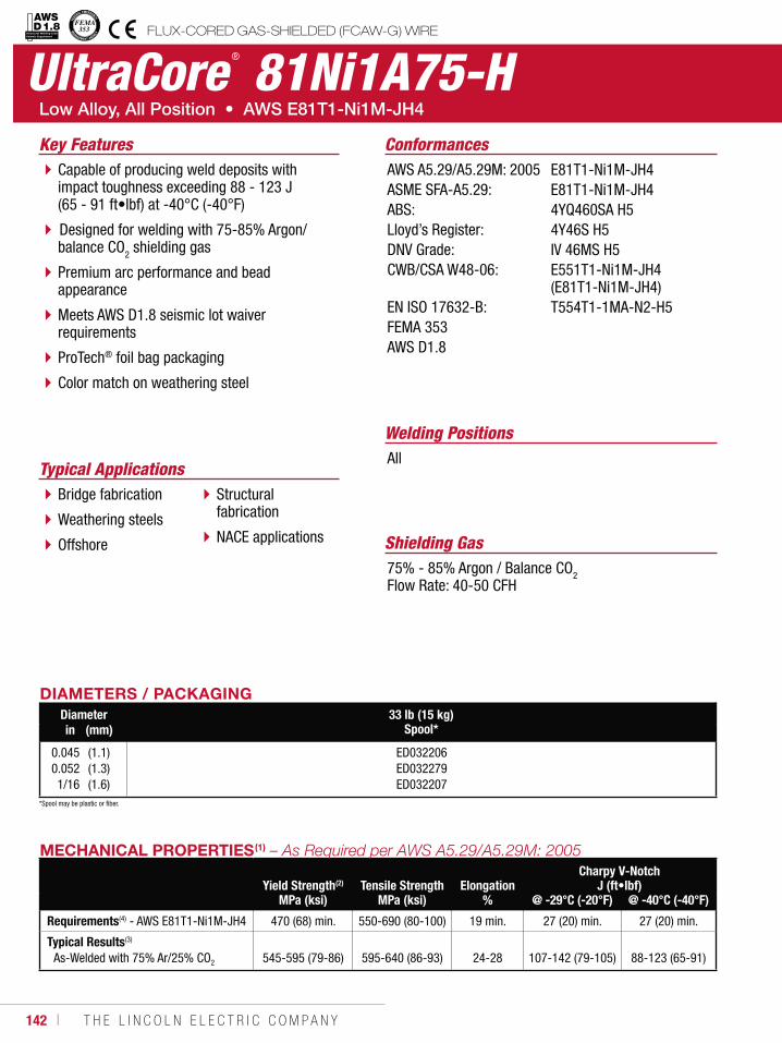
142 ı T H E L I N C O L N E L E C T R I C C O M P A N Y
UltraCore ® 81Ni1A75-H
Welding Positions
Typical ApplicationsAll
Bridge fabrication
Weathering steels
Offshore
Structural fabrication
NACE applications
Capable of producing weld deposits with impact toughness exceeding 88 - 123 J (65 - 91 ft•lbf) at -40°C (-40°F)
Designed for welding with 75-85% Argon/ balance CO2 shielding gas
Premium arc performance and bead appearance
Meets AWS D1.8 seismic lot waiver requirements
ProTech® foil bag packaging
Color match on weathering steel
Conformances
Shielding Gas75% - 85% Argon / Balance CO2Flow Rate: 40-50 CFH
Key FeaturesAWS A5.29/A5.29M: 2005ASME SFA-A5.29:ABS:Lloyd’s Register:DNV Grade:CWB/CSA W48-06:
EN ISO 17632-B:FEMA 353AWS D1.8
E81T1-Ni1M-JH4E81T1-Ni1M-JH44YQ460SA H54Y46S H5IV 46MS H5E551T1-Ni1M-JH4 (E81T1-Ni1M-JH4)T554T1-1MA-N2-H5
DIAMETERS / PACKAGINGDiameter 33 lb (15 kg)
Spool*in (mm)
0.0450.0521/16
(1.1)(1.3)(1.6)
ED032206ED032279ED032207
MECHANICAL PROPERTIES(1)
Yield Strength(2) Tensile Strength ElongationCharpy V-Notch
J (ft•lbf)MPa (ksi) MPa (ksi) % @ -29°C (-20°F) @ -40°C (-40°F)
Requirements(4) - AWS E81T1-Ni1M-JH4 470 (68) min. 550-690 (80-100) 19 min. 27 (20) min. 27 (20) min.
Typical Results(3)
As-Welded with 75% Ar/25% CO2 545-595 (79-86) 595-640 (86-93) 24-28 107-142 (79-105) 88-123 (65-91)
FLUX-CORED GAS-SHIELDED (FCAW-G) WIREStructural Welding Code Seismic Supplement
*Spool may be plastic or fiber.
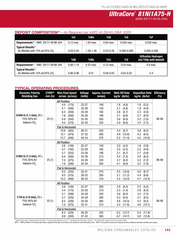
W E L D I N G C O N S U M A B L E S C A T A L O G ı 143
UltraCore ® 81Ni1A75-H(AWS E81T1-Ni1M-JH4)
DEPOSIT COMPOSITION(1) %C %Mn %Si %S %P
Requirements(4) - AWS E81T1-Ni1M-JH4 0.12 max. 1.50 max. 0.80 max. 0.030 max. 0.030 max.
Typical Results(3)
As-Welded with 75% Ar/25% CO2 0.04-0.05 1.26-1.36 0.25-0.29 0.006-0.009 0.005-0.008
%Ni %Mo %Cr %VDiffusible Hydrogen
(mL/100g weld deposit)
Requirements(4) - AWS E81T1-Ni1M-JH4 0.80-1.10 0.35 max. 0.15 max. 0.05 max. 4.0 max.
Typical Results(3)
As-Welded with 75% Ar/25% CO2 0.86-0.96 0.01 0.04-0.05 0.02-0.03 2-4
TYPICAL OPERATING PROCEDURESDiameter, Polarity
Shielding GasCTWD(5)
mm (in)Wire Feed Speed Voltage
(volts)Approx. Current
(amps)Melt-Off Rate Deposition Rate Efficiency
(%)m/min (in/min) kg/hr (lb/hr) kg/hr (lb/hr)
0.045 in (1.1 mm), DC+75%-85% Ar/ balance CO2
25 (1)
All Position
86-88
4.45.16.47.68.99.5
(175)(200)(250)(300)(350)(375)
22-2723-2824-2924-2925-3025-30
140150165190205225
1.82.12.63.13.63.9
(4.0)(4.6)(5.7)(6.8)(8.0)(8.6)
1.61.82.32.73.23.4
(3.5)(4.0)(5.0)(6.0)(7.0)(7.5)
Flat & Horizontal10.812.112.7
(425)(475)(500)
26-3127-3228-33
245265275
4.44.95.2
(9.7)(10.8)(11.4)
3.84.34.5
(8.5)(9.5)(10.0)
0.052 in (1.3 mm), DC+75%-85% Ar/ balance CO
2
25 (1)
All Position
86-88
3.84.75.76.47.07.6
(150)(185)(225)(250)(275)(300)
22-2723-2823-2824-2924-2925-30
150165190215235265
2.02.53.13.43.74.1
(4.5)(5.5)(6.7)(7.5)(8.2)(9.0)
1.82.22.72.93.23.5
(3.9)(4.8)(5.9)(6.5)(7.2)(7.8)
Flat & Horizontal8.59.5
10.2
(335)(375)(400)
25-3126-3226-33
275295310
4.55.15.4
(10.0)(11.2)(12.0)
4.04.44.7
(8.7)(9.8)(10.4)
1/16 in (1.6 mm), DC+75%-85% Ar/ balance CO
2
25 (1)
All Position
86-88
3.84.45.15.76.57.0
(150)(175)(200)(225)(250)(275)
22-2723-2824-2924-2925-3025-31
200210235265285315
2.93.33.84.34.85.3
(6.3)(7.4)(8.4)(9.5)(10.5)(11.6)
2.52.93.33.74.24.6
(5.5)(6.4)(7.3)(8.2)(9.2)(10.1)
Flat & Horizontal8.38.9
(325)(350)
26-3227-33
335365
6.26.7
(13.7)(14.7)
5.45.8
(11.9)(12.8)
(1)Typical all weld metal. (2)Measured with 0.2% offset. (3)See test results disclaimer on pg. 12. (4)As-Welded with 75% Argon / 25% CO2. (5)To estimate ESO, subtract 1/4 in (6.0 mm) from CTWD.
NOTE 1 : FEMA and AWS D1.8 structural steel seismic supplement test data can be found on this product at www.lincolnelectric.com. NOTE 2: This product contains micro-alloying elements. Additional information available upon request.
FLUX-CORED GAS-SHIELDED (FCAW-G) WIRE
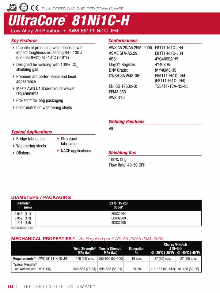
144 ı T H E L I N C O L N E L E C T R I C C O M P A N Y
UltraCore ® 81Ni1C-H
Welding Positions
Typical ApplicationsAll
Bridge fabrication
Weathering steels
Offshore
Structural fabrication
NACE applications
Capable of producing weld deposits with impact toughness exceeding 84 - 130 J (62 - 96 ft•lbf) at -40°C (-40°F)
Designed for welding with 100% CO2 shielding gas
Premium arc performance and bead appearance
Meets AWS D1.8 seismic lot waiver requirements
ProTech® foil bag packaging
Color match on weathering steels
Conformances
Shielding Gas100% CO2
Flow Rate: 40-50 CFH
Key FeaturesAWS A5.29/A5.29M: 2005ASME SFA-A5.29:ABS:Lloyd’s Register:DNV Grade:CWB/CSA W48-06:
EN ISO 17632-B:FEMA 353AWS D1.8
E81T1-Ni1C-JH4E81T1-Ni1C-JH44YQ460SA H54Y46S H5IV Y46MS H5E551T1-Ni1C-JH4 (E81T1-Ni1C-JH4)T554T1-1CA-N2-H5
DIAMETERS / PACKAGINGDiameter 33 lb (15 kg)
Spool*in (mm)
0.0450.0521/16
(1.1)(1.3)(1.6)
ED032204ED032280ED032205
MECHANICAL PROPERTIES(1)
Yield Strength(2) Tensile Strength ElongationCharpy V-Notch
J (ft•lbf)MPa (ksi) MPa (ksi) % @ -29°C (-20°F) @ -40°C (-40°F)
Requirements(4) - AWS E81T1-Ni1C-JH4 470 (68) min. 550-690 (80-100) 19 min. 27 (20) min. 27 (20) min.
Typical Results(3)
As-Welded with 100% CO2 540-585 (78-84) 595-635 (86-91) 25-28 111-152 (82-112) 84-130 (62-96)
FLUX-CORED GAS-SHIELDED (FCAW-G) WIREStructural Welding Code Seismic Supplement
*Spool may be plastic or fiber.
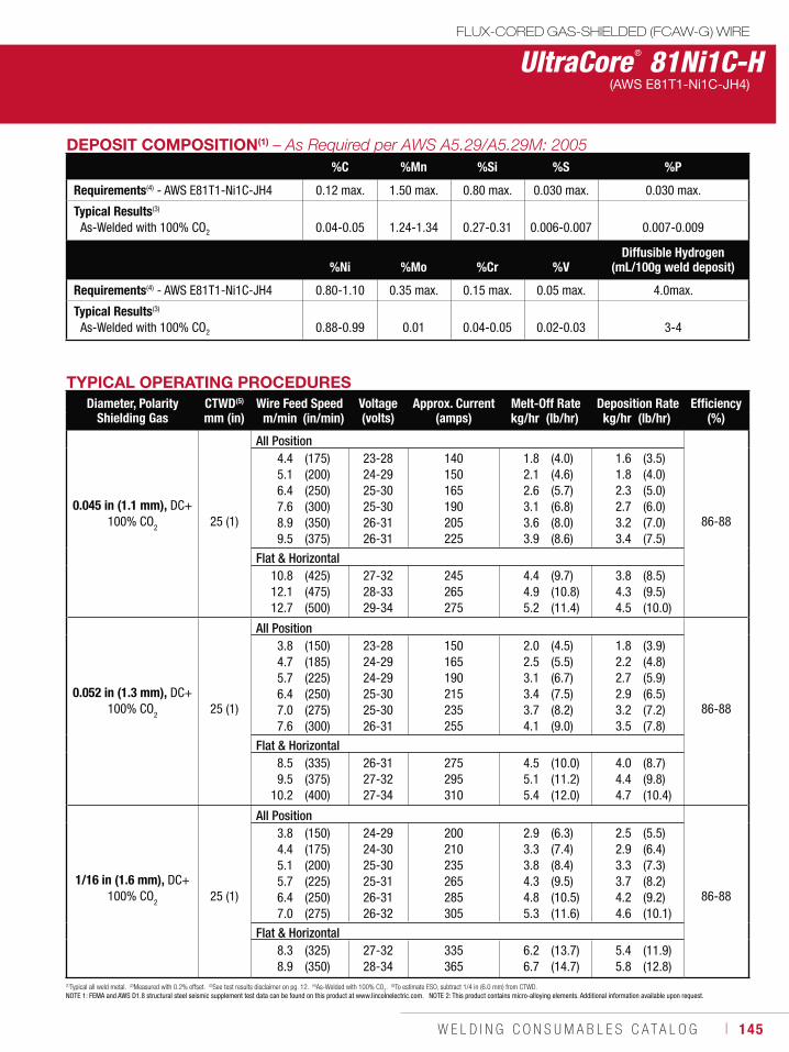
W E L D I N G C O N S U M A B L E S C A T A L O G ı 145
UltraCore ® 81Ni1C-H(AWS E81T1-Ni1C-JH4)
DEPOSIT COMPOSITION(1)
%C %Mn %Si %S %P
Requirements(4) - AWS E81T1-Ni1C-JH4 0.12 max. 1.50 max. 0.80 max. 0.030 max. 0.030 max.
Typical Results(3)
As-Welded with 100% CO2 0.04-0.05 1.24-1.34 0.27-0.31 0.006-0.007 0.007-0.009
%Ni %Mo %Cr %VDiffusible Hydrogen
(mL/100g weld deposit)
Requirements(4) - AWS E81T1-Ni1C-JH4 0.80-1.10 0.35 max. 0.15 max. 0.05 max. 4.0max.
Typical Results(3)
As-Welded with 100% CO2 0.88-0.99 0.01 0.04-0.05 0.02-0.03 3-4
TYPICAL OPERATING PROCEDURESDiameter, Polarity
Shielding GasCTWD(5)
mm (in)Wire Feed Speed Voltage
(volts)Approx. Current
(amps)Melt-Off Rate Deposition Rate Efficiency
(%)m/min (in/min) kg/hr (lb/hr) kg/hr (lb/hr)
0.045 in (1.1 mm), DC+100% CO2 25 (1)
All Position
86-88
4.45.16.47.68.99.5
(175)(200)(250)(300)(350)(375)
23-2824-2925-3025-3026-3126-31
140150165190205225
1.82.12.63.13.63.9
(4.0)(4.6)(5.7)(6.8)(8.0)(8.6)
1.61.82.32.73.23.4
(3.5)(4.0)(5.0)(6.0)(7.0)(7.5)
Flat & Horizontal10.812.112.7
(425)(475)(500)
27-3228-3329-34
245265275
4.44.95.2
(9.7)(10.8)(11.4)
3.84.34.5
(8.5)(9.5)(10.0)
0.052 in (1.3 mm), DC+100% CO
2 25 (1)
All Position
86-88
3.84.75.76.47.07.6
(150)(185)(225)(250)(275)(300)
23-2824-2924-2925-3025-3026-31
150165190215235255
2.02.53.13.43.74.1
(4.5)(5.5)(6.7)(7.5)(8.2)(9.0)
1.82.22.72.93.23.5
(3.9)(4.8)(5.9)(6.5)(7.2)(7.8)
Flat & Horizontal8.59.5
10.2
(335)(375)(400)
26-3127-3227-34
275295310
4.55.15.4
(10.0)(11.2)(12.0)
4.04.44.7
(8.7)(9.8)(10.4)
1/16 in (1.6 mm), DC+100% CO
2 25 (1)
All Position
86-88
3.84.45.15.76.47.0
(150)(175)(200)(225)(250)(275)
24-2924-3025-3025-3126-3126-32
200210235265285305
2.93.33.84.34.85.3
(6.3)(7.4)(8.4)(9.5)(10.5)(11.6)
2.52.93.33.74.24.6
(5.5)(6.4)(7.3)(8.2)(9.2)(10.1)
Flat & Horizontal8.38.9
(325)(350)
27-3228-34
335365
6.26.7
(13.7)(14.7)
5.45.8
(11.9)(12.8)
(1)Typical all weld metal. (2)Measured with 0.2% offset. (3)See test results disclaimer on pg. 12. (4)As-Welded with 100% CO2. (5)To estimate ESO, subtract 1/4 in (6.0 mm) from CTWD.
NOTE 1: FEMA and AWS D1.8 structural steel seismic supplement test data can be found on this product at www.lincolnelectric.com. NOTE 2: This product contains micro-alloying elements. Additional information available upon request.
FLUX-CORED GAS-SHIELDED (FCAW-G) WIRE
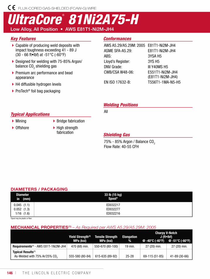
146 ı T H E L I N C O L N E L E C T R I C C O M P A N Y
UltraCore ® 81Ni2A75-HFLUX-CORED GAS-SHIELDED (FCAW-G) WIRE
Welding Positions
Typical ApplicationsAll
Mining
Offshore
Bridge fabrication
High strength fabrication
Capable of producing weld deposits with impact toughness exceeding 41 - 89 J (30 - 66 ft•lbf) at -51°C (-60°F)
Designed for welding with 75-85% Argon/ balance CO2 shielding gas
Premium arc performance and bead appearance
H4 diffusible hydrogen levels
ProTech® foil bag packaging
Conformances
Shielding Gas75% - 85% Argon / Balance CO2
Flow Rate: 40-55 CFH
Key FeaturesAWS A5.29/A5.29M: 2005ASME SFA-A5.29:ABS:Lloyd’s Register:DNV Grade:CWB/CSA W48-06:
EN ISO 17632-B:
E81T1-Ni2M-JH4E81T1-Ni2M-JH43YSA H53YS H5III Y40MS H5E551T1-Ni2M-JH4 (E81T1-Ni2M-JH4)T556T1-1MA-N5-H5
DIAMETERS / PACKAGINGDiameter 33 lb (15 kg)
Spool*in (mm)
0.0450.0521/16
(1.1)(1.3)(1.6)
ED032217ED032277ED032216
MECHANICAL PROPERTIES(1)
Yield Strength(2) Tensile Strength ElongationCharpy V-Notch
J (ft•lbf)MPa (ksi) MPa (ksi) % @ -40°C (-40°F) @ -51°C (-60°F)
Requirements(4) - AWS E81T-1Ni2M-JH4 470 (68) min. 550-670 (80-100) 19 min. 27 (20) min. 27 (20) min.
Typical Results(3)
As-Welded with 75% Ar/25% CO2 555-580 (80-84) 615-635 (89-92) 25-28 69-115 (51-85) 41-89 (30-66)
*Spool may be plastic or fiber.

W E L D I N G C O N S U M A B L E S C A T A L O G ı 147
UltraCore ® 81Ni2A75-HFLUX-CORED GAS-SHIELDED (FCAW-G) WIRE
(AWS E81T1-Ni2M-JH4)
DEPOSIT COMPOSITION(1) %C %Mn %Si %S
Requirements(4) - AWS E81T1-Ni2M-JH4 0.12 max. 1.50 max. 0.80 max. 0.030 max.
Typical Results(3)
As-Welded with 75% Ar/25% CO2 0.04-0.05 0.93-1.05 0.25-0.28 0.005-0.006
%P %NiDiffusible Hydrogen
(mL/100g weld deposit)
Requirements(4) - AWS E81T1-Ni2M-JH4 0.030 max. 1.75-2.75 4.0 max.
Typical Results(3)
As-Welded with 75% Ar/25% CO2 0.006-0.008 2.01-2.13 3-4
TYPICAL OPERATING PROCEDURESDiameter, Polarity
Shielding GasCTWD(5)
mm (in)Wire Feed Speed Voltage
(volts)Approx. Current
(amps)Melt-Off Rate Deposition Rate Efficiency
(%)m/min (in/min) kg/hr (lb/hr) kg/hr (lb/hr)
0.045 in (1.1 mm), DC+75%-85% Ar/ balance CO2
25 (1)
All Position
86-88
4.45.16.47.68.99.5
(175)(200)(250)(300)(350)(375)
21-2622-2722-2723-2824-2924-29
140150165190205225
1.82.12.63.13.63.9
(4.0)(4.6)(5.7)(6.8)(8.0)(8.6)
1.61.82.32.73.23.4
(3.5)(4.0)(5.0)(6.0)(7.0)(7.5)
Flat & Horizontal10.812.112.7
(425)(475)(500)
25-3026-3127-32
245265275
4.44.95.2
(9.7)(10.8)(11.4)
3.84.34.5
(8.5)(9.5)(10.0)
0.052 in (1.3 mm), DC+75%-85% Ar/ balance CO
2
25 (1)
All Position
86-88
3.84.75.76.47.07.6
(150)(185)(225)(250)(275)(300)
21-2622-2722-2723-2823-2824-29
150165190215235255
2.02.53.13.43.74.1
(4.5)(5.5)(6.7)(7.5)(8.2)(9.0)
1.82.22.72.93.23.5
(3.9)(4.8)(5.9)(6.5)(7.2)(7.8)
Flat & Horizontal8.59.5
10.2
(335)(375)(400)
24-3025-3125-32
275295310
4.55.15.4
(10.0)(11.2)(12.0)
4.04.44.7
(8.7)(9.8)(10.4)
1/16 in (1.6 mm), DC+75%-85% Ar/ balance CO
2
25 (1)
All Position
86-88
3.84.45.15.76.47.0
(150)(175)(200)(225)(250)(275)
21-2721-2822-2923-3024-3124-32
200210235265285315
2.93.33.84.34.85.3
(6.3)(7.4)(8.4)(9.5)(10.5)(11.6)
2.52.93.33.74.24.6
(5.5)(6.4)(7.3)(8.2)(9.2)(10.1)
Flat & Horizontal8.38.9
(325)(350)
24-3225-33
335365
6.26.7
(13.7)(14.7)
5.45.8
(11.9)(12.8)
(1)Typical all weld metal. (2)Measured with 0.2% offset. (3)See test results disclaimer on pg. 12. (4)As-Welded with 75% Argon / 25% CO2. (5)To estimate ESO, subtract 1/4 in (6.0 mm) from CTWD.
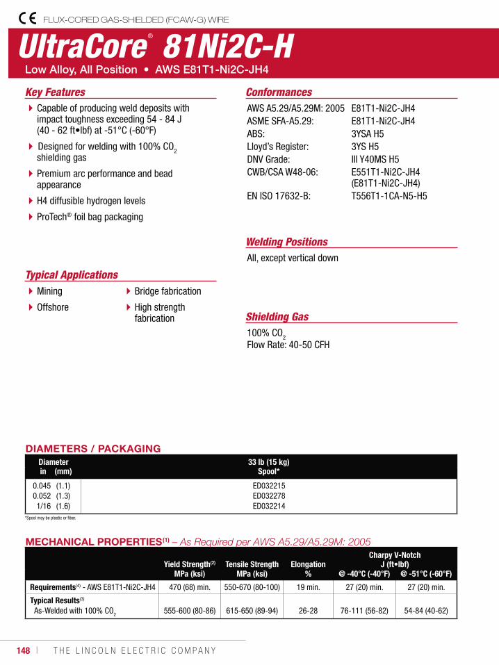
148 ı T H E L I N C O L N E L E C T R I C C O M P A N Y
UltraCore ® 81Ni2C-HFLUX-CORED GAS-SHIELDED (FCAW-G) WIRE
Welding Positions
Typical Applications
All, except vertical down
Mining
Offshore
Bridge fabrication
High strength fabrication
Capable of producing weld deposits with impact toughness exceeding 54 - 84 J (40 - 62 ft•lbf) at -51°C (-60°F)
Designed for welding with 100% CO2 shielding gas
Premium arc performance and bead appearance
H4 diffusible hydrogen levels
ProTech® foil bag packaging
Conformances
Shielding Gas100% CO2
Flow Rate: 40-50 CFH
Key FeaturesAWS A5.29/A5.29M: 2005ASME SFA-A5.29:ABS:Lloyd’s Register:DNV Grade:CWB/CSA W48-06:
EN ISO 17632-B:
E81T1-Ni2C-JH4E81T1-Ni2C-JH43YSA H53YS H5III Y40MS H5E551T1-Ni2C-JH4 (E81T1-Ni2C-JH4)T556T1-1CA-N5-H5
DIAMETERS / PACKAGINGDiameter 33 lb (15 kg)
Spool*in (mm)
0.0450.0521/16
(1.1)(1.3)(1.6)
ED032215ED032278ED032214
MECHANICAL PROPERTIES(1)
Yield Strength(2) Tensile Strength ElongationCharpy V-Notch
J (ft•lbf)MPa (ksi) MPa (ksi) % @ -40°C (-40°F) @ -51°C (-60°F)
Requirements(4) - AWS E81T1-Ni2C-JH4 470 (68) min. 550-670 (80-100) 19 min. 27 (20) min. 27 (20) min.
Typical Results(3)
As-Welded with 100% CO2 555-600 (80-86) 615-650 (89-94) 26-28 76-111 (56-82) 54-84 (40-62)
*Spool may be plastic or fiber.
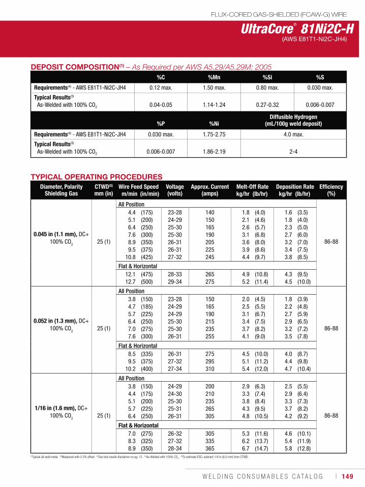
W E L D I N G C O N S U M A B L E S C A T A L O G ı 149
UltraCore ® 81Ni2C-HFLUX-CORED GAS-SHIELDED (FCAW-G) WIRE
(AWS E81T1-Ni2C-JH4)
DEPOSIT COMPOSITION(1) %C %Mn %Si %S
Requirements(4) - AWS E81T1-Ni2C-JH4 0.12 max. 1.50 max. 0.80 max. 0.030 max.
Typical Results(3)
As-Welded with 100% CO2 0.04-0.05 1.14-1.24 0.27-0.32 0.006-0.007
%P %NiDiffusible Hydrogen
(mL/100g weld deposit)
Requirements(4) - AWS E81T1-Ni2C-JH4 0.030 max. 1.75-2.75 4.0 max.
Typical Results(3)
As-Welded with 100% CO2 0.006-0.007 1.86-2.19 2-4
TYPICAL OPERATING PROCEDURESDiameter, Polarity
Shielding GasCTWD(5)
mm (in)Wire Feed Speed Voltage
(volts)Approx. Current
(amps)Melt-Off Rate Deposition Rate Efficiency
(%)m/min (in/min) kg/hr (lb/hr) kg/hr (lb/hr)
0.045 in (1.1 mm), DC+100% CO2 25 (1)
All Position
86-88
4.45.16.47.68.99.5
10.8
(175)(200)(250)(300)(350)(375)(425)
23-2824-2925-3025-3026-3126-3127-32
140150165190205225245
1.82.12.63.13.63.94.4
(4.0)(4.6)(5.7)(6.8)(8.0)(8.6)(9.7)
1.61.82.32.73.23.43.8
(3.5)(4.0)(5.0)(6.0)(7.0)(7.5)(8.5)
Flat & Horizontal12.112.7
(475)(500)
28-3329-34
265275
4.95.2
(10.8)(11.4)
4.34.5
(9.5)(10.0)
0.052 in (1.3 mm), DC+100% CO
2 25 (1)
All Position
86-88
3.84.75.76.47.07.6
(150)(185)(225)(250)(275)(300)
23-2824-2924-2925-3025-3026-31
150165190215235255
2.02.53.13.43.74.1
(4.5)(5.5)(6.7)(7.5)(8.2)(9.0)
1.82.22.72.93.23.5
(3.9)(4.8)(5.9)(6.5)(7.2)(7.8)
Flat & Horizontal8.59.5
10.2
(335)(375)(400)
26-3127-3227-34
275295310
4.55.15.4
(10.0)(11.2)(12.0)
4.04.44.7
(8.7)(9.8)(10.4)
1/16 in (1.6 mm), DC+100% CO
2 25 (1)
All Position
86-88
3.84.45.15.76.4
(150)(175)(200)(225)(250)
24-2924-3025-3025-3126-31
200210235265305
2.93.33.84.34.8
(6.3)(7.4)(8.4)(9.5)(10.5)
2.52.93.33.74.2
(5.5)(6.4)(7.3)(8.2)(9.2)
Flat & Horizontal7.08.38.9
(275)(325)(350)
26-3227-3228-34
305335365
5.36.26.7
(11.6)(13.7)(14.7)
4.65.45.8
(10.1)(11.9)(12.8)
(1)Typical all weld metal. (2)Measured with 0.2% offset. (3)See test results disclaimer on pg. 12. (4)As-Welded with 100% CO2. (5)To estimate ESO, subtract 1/4 in (6.0 mm) from CTWD.
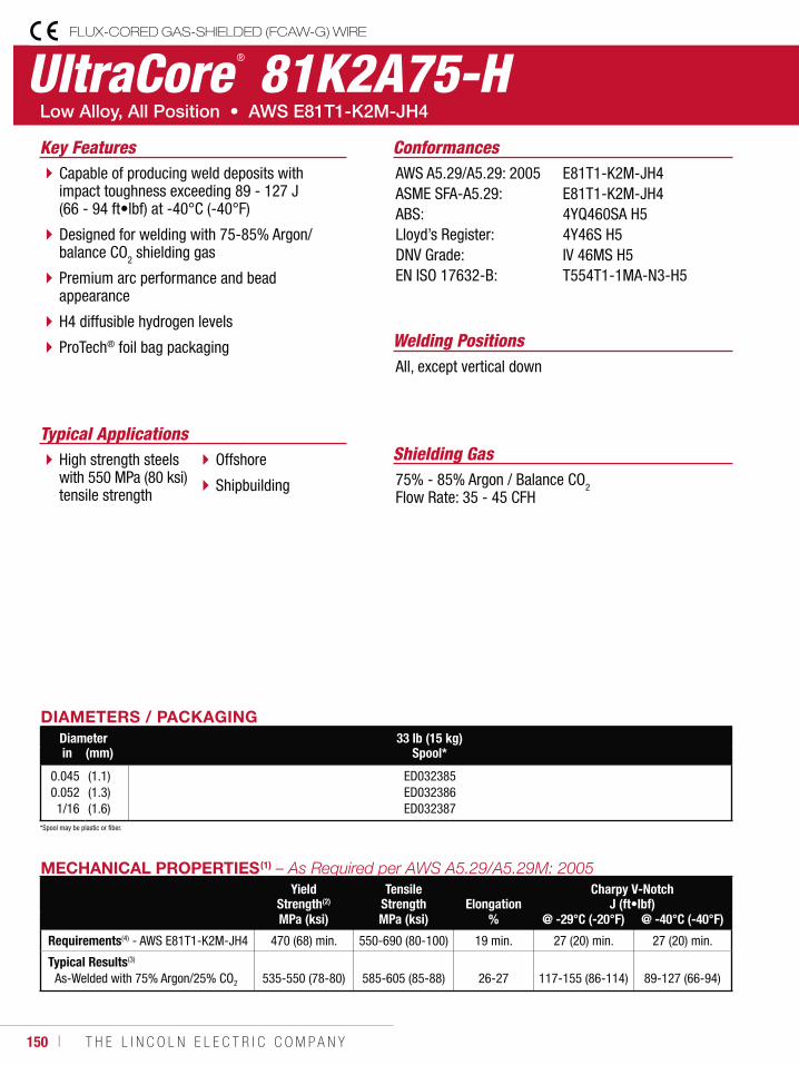
150 ı T H E L I N C O L N E L E C T R I C C O M P A N Y
UltraCore ® 81K2A75-HFLUX-CORED GAS-SHIELDED (FCAW-G) WIRE
Welding Positions
Typical Applications
All, except vertical down
High strength steels with 550 MPa (80 ksi) tensile strength
Offshore
Shipbuilding
Capable of producing weld deposits with impact toughness exceeding 89 - 127 J (66 - 94 ft•lbf) at -40°C (-40°F)
Designed for welding with 75-85% Argon/ balance CO2 shielding gas
Premium arc performance and bead appearance
H4 diffusible hydrogen levels
ProTech® foil bag packaging
Conformances
Shielding Gas75% - 85% Argon / Balance CO2Flow Rate: 35 - 45 CFH
Key FeaturesAWS A5.29/A5.29: 2005ASME SFA-A5.29:ABS:Lloyd’s Register:DNV Grade:EN ISO 17632-B:
E81T1-K2M-JH4E81T1-K2M-JH44YQ460SA H54Y46S H5IV 46MS H5T554T1-1MA-N3-H5
DIAMETERS / PACKAGINGDiameter 33 lb (15 kg)
Spool*in (mm)
0.0450.0521/16
(1.1)(1.3)(1.6)
ED032385ED032386ED032387
MECHANICAL PROPERTIES(1) Yield
Strength(2)Tensile
Strength ElongationCharpy V-Notch
J (ft•lbf)MPa (ksi) MPa (ksi) % @ -29°C (-20°F) @ -40°C (-40°F)
Requirements(4) - AWS E81T1-K2M-JH4 470 (68) min. 550-690 (80-100) 19 min. 27 (20) min. 27 (20) min.
Typical Results(3)
As-Welded with 75% Argon/25% CO2 535-550 (78-80) 585-605 (85-88) 26-27 117-155 (86-114) 89-127 (66-94)
*Spool may be plastic or fiber.
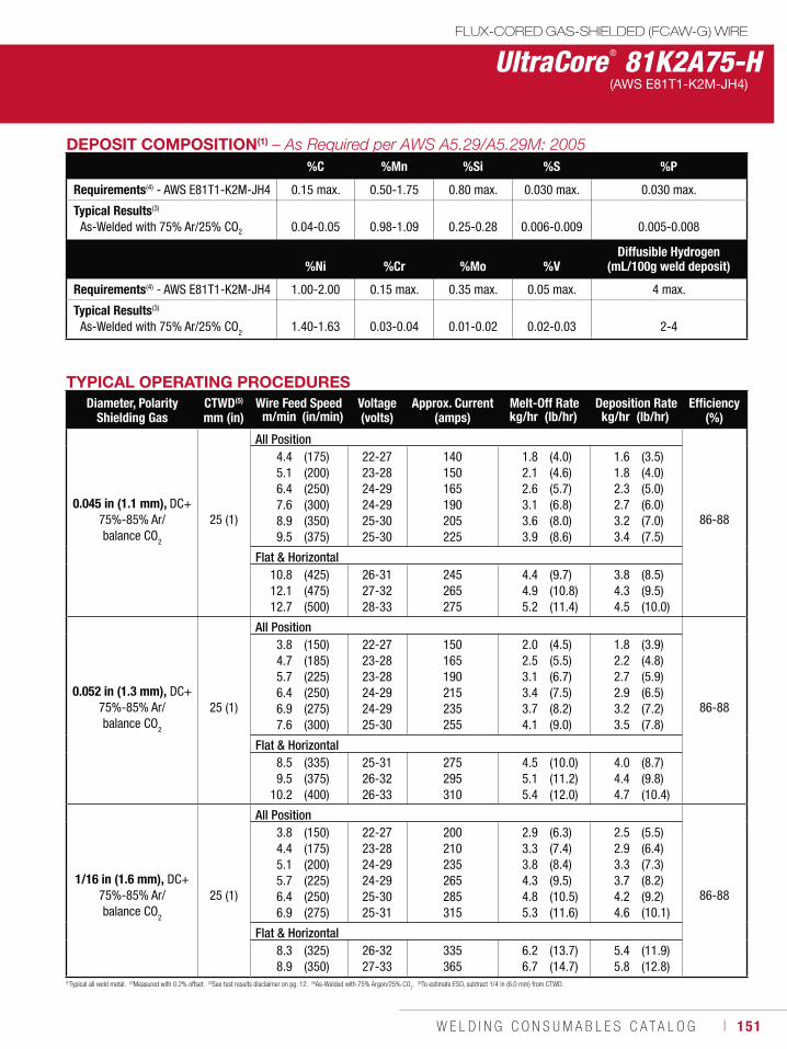
W E L D I N G C O N S U M A B L E S C A T A L O G ı 151
UltraCore ® 81K2A75-HFLUX-CORED GAS-SHIELDED (FCAW-G) WIRE
(AWS E81T1-K2M-JH4)
DEPOSIT COMPOSITION(1)
%C %Mn %Si %S %P
Requirements(4) - AWS E81T1-K2M-JH4 0.15 max. 0.50-1.75 0.80 max. 0.030 max. 0.030 max.
Typical Results(3)
As-Welded with 75% Ar/25% CO2 0.04-0.05 0.98-1.09 0.25-0.28 0.006-0.009 0.005-0.008
%Ni %Cr %Mo %VDiffusible Hydrogen
(mL/100g weld deposit)
Requirements(4) - AWS E81T1-K2M-JH4 1.00-2.00 0.15 max. 0.35 max. 0.05 max. 4 max.
Typical Results(3)
As-Welded with 75% Ar/25% CO2 1.40-1.63 0.03-0.04 0.01-0.02 0.02-0.03 2-4
TYPICAL OPERATING PROCEDURESDiameter, Polarity
Shielding GasCTWD(5)
mm (in)Wire Feed Speed Voltage
(volts)Approx. Current
(amps)Melt-Off Rate Deposition Rate Efficiency
(%)m/min (in/min) kg/hr (lb/hr) kg/hr (lb/hr)
0.045 in (1.1 mm), DC+75%-85% Ar/ balance CO
2
25 (1)
All Position
86-88
4.45.16.47.68.99.5
(175)(200)(250)(300)(350)(375)
22-2723-2824-2924-2925-3025-30
140150165190205225
1.82.12.63.13.63.9
(4.0)(4.6)(5.7)(6.8)(8.0)(8.6)
1.61.82.32.73.23.4
(3.5)(4.0)(5.0)(6.0)(7.0)(7.5)
Flat & Horizontal10.812.112.7
(425)(475)(500)
26-3127-3228-33
245265275
4.44.95.2
(9.7)(10.8)(11.4)
3.84.34.5
(8.5)(9.5)(10.0)
0.052 in (1.3 mm), DC+75%-85% Ar/ balance CO
2
25 (1)
All Position
86-88
3.84.75.76.46.97.6
(150)(185)(225)(250)(275)(300)
22-2723-2823-2824-2924-2925-30
150165190215235255
2.02.53.13.43.74.1
(4.5)(5.5)(6.7)(7.5)(8.2)(9.0)
1.82.22.72.93.23.5
(3.9)(4.8)(5.9)(6.5)(7.2)(7.8)
Flat & Horizontal8.59.5
10.2
(335)(375)(400)
25-3126-3226-33
275295310
4.55.15.4
(10.0)(11.2)(12.0)
4.04.44.7
(8.7)(9.8)(10.4)
1/16 in (1.6 mm), DC+75%-85% Ar/ balance CO
2
25 (1)
All Position
86-88
3.84.45.15.76.46.9
(150)(175)(200)(225)(250)(275)
22-2723-2824-2924-2925-3025-31
200210235265285315
2.93.33.84.34.85.3
(6.3)(7.4)(8.4)(9.5)(10.5)(11.6)
2.52.93.33.74.24.6
(5.5)(6.4)(7.3)(8.2)(9.2)(10.1)
Flat & Horizontal8.38.9
(325)(350)
26-3227-33
335365
6.26.7
(13.7)(14.7)
5.45.8
(11.9)(12.8)
(1)Typical all weld metal. (2)Measured with 0.2% offset. (3)See test results disclaimer on pg. 12. (4)As-Welded with 75% Argon/25% CO2. (5)To estimate ESO, subtract 1/4 in (6.0 mm) from CTWD.
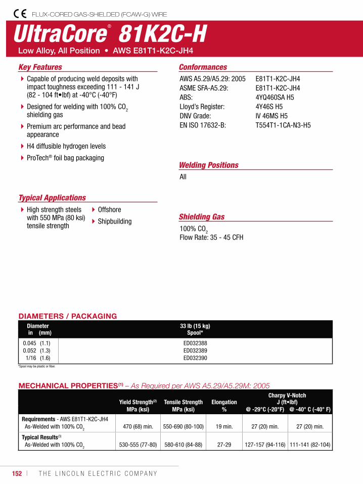
152 ı T H E L I N C O L N E L E C T R I C C O M P A N Y
UltraCore ® 81K2C-HFLUX-CORED GAS-SHIELDED (FCAW-G) WIRE
Welding Positions
Typical Applications
All
High strength steels with 550 MPa (80 ksi) tensile strength
Offshore
Shipbuilding
Capable of producing weld deposits with impact toughness exceeding 111 - 141 J (82 - 104 ft•lbf) at -40°C (-40°F)
Designed for welding with 100% CO2 shielding gas
Premium arc performance and bead appearance
H4 diffusible hydrogen levels
ProTech® foil bag packaging
Conformances
Shielding Gas100% CO2
Flow Rate: 35 - 45 CFH
Key FeaturesAWS A5.29/A5.29: 2005ASME SFA-A5.29:ABS:Lloyd’s Register:DNV Grade:EN ISO 17632-B:
E81T1-K2C-JH4E81T1-K2C-JH44YQ460SA H54Y46S H5IV 46MS H5T554T1-1CA-N3-H5
DIAMETERS / PACKAGINGDiameter 33 lb (15 kg)
Spool*in (mm)
0.0450.0521/16
(1.1)(1.3)(1.6)
ED032388ED032389ED032390
MECHANICAL PROPERTIES(1)
Yield Strength(2) Tensile Strength ElongationCharpy V-Notch
J (ft•lbf)MPa (ksi) MPa (ksi) % @ -29°C (-20°F) @ -40° C (-40° F)
Requirements - AWS E81T1-K2C-JH4As-Welded with 100% CO2
470 (68) min.
550-690 (80-100)
19 min.
27 (20) min.
27 (20) min.
Typical Results(3)
As-Welded with 100% CO2 530-555 (77-80) 580-610 (84-88) 27-29 127-157 (94-116) 111-141 (82-104)
*Spool may be plastic or fiber.
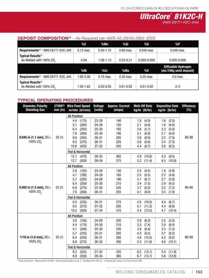
W E L D I N G C O N S U M A B L E S C A T A L O G ı 153
DEPOSIT COMPOSITION(1) %C %Mn %Si %S %P
Requirements(4) - AWS E81T1-K2C-JH4 0.15 max. 0.50-1.75 0.80 max. 0.030 max. 0.030 max.
Typical Results(3)
As-Welded with 100% CO2 0.04 1.08-1.15 0.23-0.31 0.005-0.009 0.005-0.009
%Ni %Cr %Mo %VDiffusible Hydrogen
(mL/100g weld deposit)
Requirements(4) - AWS E81T1-K2C-JH4 1.00-2.00 0.15 max. 0.35 max. 0.05 max. 4.0 max.
Typical Results(3)
As-Welded with 100% CO2 1.30-1.62 0.03-0.05 0.01-0.02 0.01-0.02 2-3
UltraCore ® 81K2C-HFLUX-CORED GAS-SHIELDED (FCAW-G) WIRE
(AWS E81T1-K2C-JH4)
TYPICAL OPERATING PROCEDURESDiameter, Polarity
Shielding GasCTWD(5)
mm (in)Wire Feed Speed Voltage
(volts)Approx. Current
(amps)Melt-Off Rate Deposition Rate Efficiency
(%)m/min (in/min) kg/hr (lb/hr) kg/hr (lb/hr)
0.045 in (1.1 mm), DC+100% CO2
25 (1)
All Position
86-88
4.45.16.47.68.99.5
10.8
(175)(200)(250)(300)(350)(375)(425)
23-2824-2925-3025-3026-3126-3127-32
140150165190205225245
1.82.12.63.13.63.94.4
(4.0)(4.6)(5.7)(6.8)(8.0)(8.6)(9.7)
1.61.82.32.73.23.43.8
(3.5)(4.0)(5.0)(6.0)(7.0)(7.5)(8.5)
Flat & Horizontal12.112.7
(475)(500)
28-3329-34
265275
4.95.2
(10.8)(11.4)
4.34.5
(9.5)(10.0)
0.052 in (1.3 mm), DC+100% CO
2
25 (1)
All Position
86-88
3.84.75.76.46.97.6
(150)(185)(225)(250)(275)(300)
23-2824-2924-2925-3025-3026-31
150165190215235255
2.02.53.13.43.74.1
(4.5)(5.5)(6.7)(7.5)(8.2)(9.0)
1.82.22.72.93.23.5
(3.9)(4.8)(5.9)(6.5)(7.2)(7.8)
Flat & Horizontal8.59.5
10.2
(335)(375)(400)
26-3127-3227-34
275295310
4.55.15.4
(10.0)(11.2)(12.0)
4.04.44.7
(8.7)(9.8)(10.4)
1/16 in (1.6 mm), DC+100% CO
2
25 (1)
All Position
86-88
3.84.45.15.76.46.9
(150)(175)(200)(225)(250)(275)
24-2924-3025-3025-3126-3126-32
200210235265285305
2.93.33.84.34.85.3
(6.3)(7.4)(8.4)(9.5)(10.5)(11.6)
2.52.93.33.74.24.6
(5.5)(6.4)(7.3)(8.2)(9.2)(10.1)
Flat & Horizontal8.38.9
(325)(350)
27-3228-34
335365
6.26.7
(13.7)(14.7)
5.45.8
(11.9)(12.8)
(1)Typical all weld metal. (2)Measured with 0.2% offset. (3)See test results disclaimer on pg. 12. (4)As-Welded with 100% CO2. (5)To estimate ESO, subtract 1/4 in (6.0 mm) from CTWD.
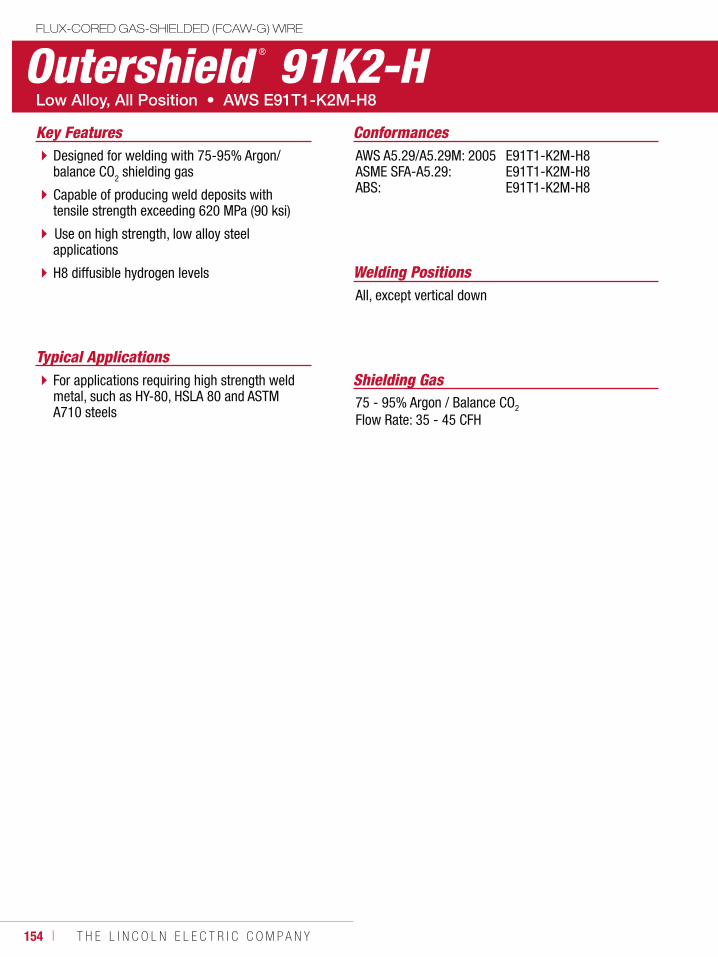
154 ı T H E L I N C O L N E L E C T R I C C O M P A N Y
Outershield ® 91K2-HFLUX-CORED GAS-SHIELDED (FCAW-G) WIRE
Welding Positions
Typical Applications
All, except vertical down
For applications requiring high strength weld metal, such as HY-80, HSLA 80 and ASTM A710 steels
Designed for welding with 75-95% Argon/ balance CO2 shielding gas
Capable of producing weld deposits with tensile strength exceeding 620 MPa (90 ksi)
Use on high strength, low alloy steel applications
H8 diffusible hydrogen levels
Conformances
Shielding Gas75 - 95% Argon / Balance CO2
Flow Rate: 35 - 45 CFH
Key FeaturesAWS A5.29/A5.29M: 2005ASME SFA-A5.29:ABS:
E91T1-K2M-H8E91T1-K2M-H8E91T1-K2M-H8
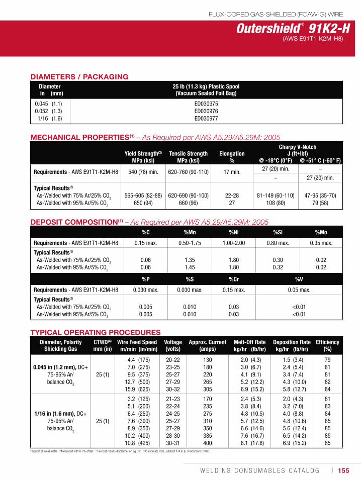
W E L D I N G C O N S U M A B L E S C A T A L O G ı 155
MECHANICAL PROPERTIES(1)
Yield Strength(2) Tensile Strength ElongationCharpy V-Notch
J (ft•lbf)MPa (ksi) MPa (ksi) % @ -18°C (0°F) @ -51° C (-60° F)
Requirements - AWS E91T1-K2M-H8 540 (78) min. 620-760 (90-110) 17 min. 27 (20) min. –
– 27 (20) min.
Typical Results(3)
As-Welded with 75% Ar/25% CO2
As-Welded with 95% Ar/5% CO2
565-605 (82-88)650 (94)
620-690 (90-100)660 (96)
22-2827
81-149 (60-110)108 (80)
47-95 (35-70)79 (58)
Outershield ® 91K2-HFLUX-CORED GAS-SHIELDED (FCAW-G) WIRE
(AWS E91T1-K2M-H8)
TYPICAL OPERATING PROCEDURESDiameter, Polarity
Shielding GasCTWD(4)
mm (in)Wire Feed Speed Voltage
(volts)Approx. Current
(amps)Melt-Off Rate Deposition Rate Efficiency
(%)m/min (in/min) kg/hr (lb/hr) kg/hr (lb/hr)
0.045 in (1.2 mm), DC+ 75-95% Ar/ balance CO2
25 (1)
4.47.09.5
12.7 15.9
(175)(275)(375)(500)(625)
20-22 23-25 25-27 27-29 30-32
130 180 220 265 305
2.03.04.1 5.2 6.9
(4.3)(6.7)(9.1)(12.2)(15.2)
1.5 2.4 3.44.35.8
(3.4)(5.4)(7.4)(10.0)(12.7)
79 81 81 82 84
1/16 in (1.6 mm), DC+ 75-95% Ar/ balance CO
2
25 (1)
3.25.1 6.4 7.68.9
10.210.8
(125)(200)(250)(300)(350)(400)(425)
21-23 22-24 24-25 25-27 27-29 28-30 30-31
170 235 275 310 350 385 400
2.43.84.85.76.67.6 8.1
(5.3)(8.4)(10.5)(12.5)(14.6)(16.7)(17.8)
2.03.2 4.0 4.8 5.66.56.9
(4.3)(7.0)(8.8)(10.6)(12.4)(14.2)(15.2)
81 83 84 85 85 85 85
(1)Typical all weld metal. (2)Measured with 0.2% offset. (3)See test results disclaimer on pg. 12. (4)To estimate ESO, subtract 1/4 in (6.0 mm) from CTWD.
DEPOSIT COMPOSITION(1)
%C %Mn %Ni %Si %Mo
Requirements - AWS E91T1-K2M-H8 0.15 max. 0.50-1.75 1.00-2.00 0.80 max. 0.35 max.
Typical Results(3)
As-Welded with 75% Ar/25% CO2
As-Welded with 95% Ar/5% CO2
0.06 0.06
1.35 1.45
1.801.80
0.30 0.32
0.020.02
%P %S %Cr %V
Requirements - AWS E91T1-K2M-H8 0.030 max. 0.030 max. 0.15 max. 0.05 max.
Typical Results(3)
As-Welded with 75% Ar/25% CO2
As-Welded with 95% Ar/5% CO2
0.005 0.005
0.010 0.010
0.030.03
<0.01 <0.01
DIAMETERS / PACKAGINGDiameter 25 lb (11.3 kg) Plastic Spool
(Vacuum Sealed Foil Bag)in (mm)
0.0450.0521/16
(1.1)(1.3)(1.6)
ED030975 ED030976 ED030977
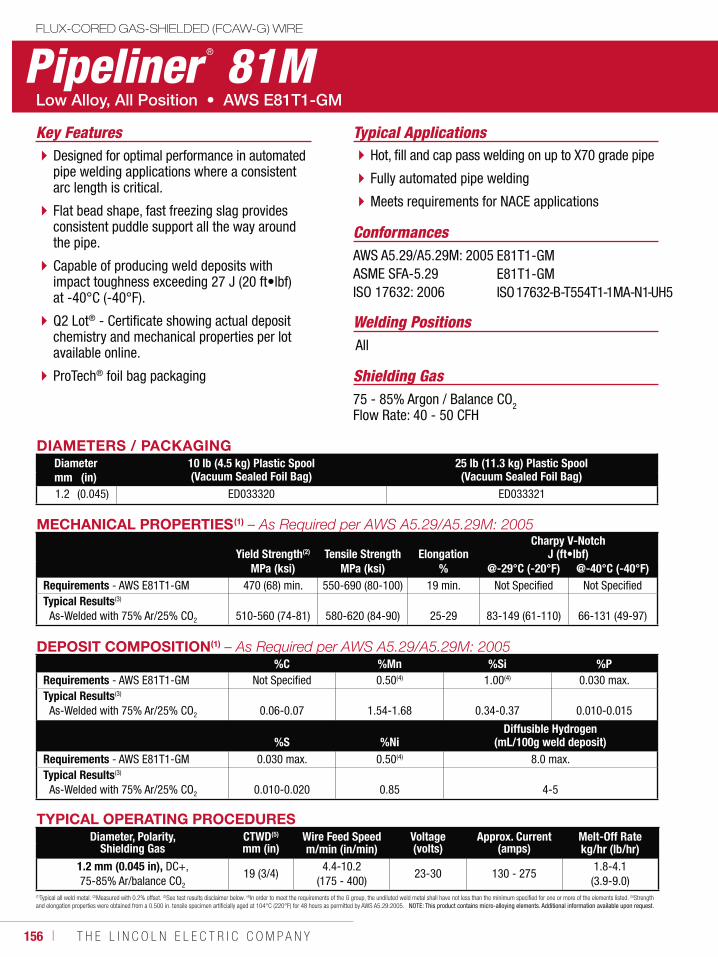
156 ı T H E L I N C O L N E L E C T R I C C O M P A N Y
DIAMETERS / PACKAGINGDiameter 10 lb (4.5 kg) Plastic Spool
(Vacuum Sealed Foil Bag)25 lb (11.3 kg) Plastic Spool(Vacuum Sealed Foil Bag)mm (in)
1.2 (0.045) ED033320 ED033321
Pipeliner ® 81MFLUX-CORED GAS-SHIELDED (FCAW-G) WIRE
Welding Positions
Typical Applications
All
Hot, fill and cap pass welding on up to X70 grade pipe
Fully automated pipe welding
Meets requirements for NACE applications
Designed for optimal performance in automated pipe welding applications where a consistent arc length is critical.
Flat bead shape, fast freezing slag provides consistent puddle support all the way around the pipe.
Capable of producing weld deposits with impact toughness exceeding 27 J (20 ft•lbf) at -40°C (-40°F).
Q2 Lot® - Certificate showing actual deposit chemistry and mechanical properties per lot available online.
ProTech® foil bag packaging
Conformances
Shielding Gas75 - 85% Argon / Balance CO2Flow Rate: 40 - 50 CFH
Key Features
AWS A5.29/A5.29M: 2005ASME SFA-5.29ISO 17632: 2006
E81T1-GME81T1-GMISO 17632-B-T554T1-1MA-N1-UH5
TYPICAL OPERATING PROCEDURESDiameter, Polarity,
Shielding GasCTWD(5)
mm (in)Wire Feed Speed Voltage
(volts)Approx. Current
(amps)Melt-Off Rate
m/min (in/min) kg/hr (lb/hr)1.2 mm (0.045 in), DC+, 75-85% Ar/balance CO2
19 (3/4)4.4-10.2
(175 - 400)23-30 130 - 275
1.8-4.1 (3.9-9.0)
(1)Typical all weld metal. (2)Measured with 0.2% offset. (3)See test results disclaimer below. (4)In order to meet the requirements of the G group, the undiluted weld metal shall have not less than the minimum specified for one or more of the elements listed. (5)Strength and elongation properties were obtained from a 0.500 in. tensile specimen artificially aged at 104°C (220°F) for 48 hours as permitted by AWS A5.29:2005. NOTE: This product contains micro-alloying elements. Additional information available upon request.
MECHANICAL PROPERTIES(1)
Yield Strength(2) Tensile Strength ElongationCharpy V-Notch
J (ft•lbf)MPa (ksi) MPa (ksi) % @-29°C (-20°F) @-40°C (-40°F)
Requirements - AWS E81T1-GM 470 (68) min. 550-690 (80-100) 19 min. Not Specified Not SpecifiedTypical Results(3)
As-Welded with 75% Ar/25% CO2 510-560 (74-81) 580-620 (84-90) 25-29 83-149 (61-110) 66-131 (49-97)
DEPOSIT COMPOSITION(1)
%C %Mn %Si %PRequirements - AWS E81T1-GM Not Specified 0.50(4) 1.00(4) 0.030 max.Typical Results(3)
As-Welded with 75% Ar/25% CO2 0.06-0.07 1.54-1.68 0.34-0.37 0.010-0.015
%S %NiDiffusible Hydrogen
(mL/100g weld deposit)Requirements - AWS E81T1-GM 0.030 max. 0.50(4) 8.0 max.Typical Results(3)
As-Welded with 75% Ar/25% CO2 0.010-0.020 0.85 4-5
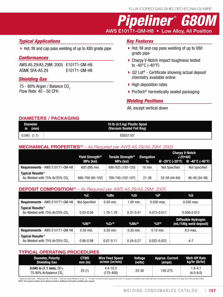
W E L D I N G C O N S U M A B L E S C A T A L O G ı 157
Pipeliner ® G80MFLUX-CORED GAS-SHIELDED (FCAW-G) WIRE
Welding Positions
Typical Applications
All, except vertical down
Hot, fill and cap pass welding of up to X80 grade pipe Hot, fill and cap pass welding of up to X80 grade pipe
Charpy V-Notch impact toughness tested to -40°C (-40°F)
Q2 Lot® - Certificate showing actual depositchemistry available online
High deposition rates
ProTech® hermetically sealed packaging
Conformances
Shielding Gas75 - 80% Argon / Balance CO2Flow Rate: 40 - 50 CFH
Key Features
AWS A5.29/A5.29M: 2005ASME SFA-A5.29
E101T1-GM-H8E101T1-GM-H8
DIAMETERS / PACKAGINGDiameter 10 lb (4.5 kg) Plastic Spool
(Vacuum Sealed Foil Bag)in (mm)
0.045 (1.1) ED031107
(1)Typical all weld metal. (2)Measured with 0.2% offset. (3)See test results disclaimer on pg. 12. (4)In order to meet the alloy requirements of the “G” group, the undiluted weld metal shall have not less than the minimum of at least one of the elements listed. NOTE: This product contains micro-alloying elements. Additional information available upon request.
DEPOSIT COMPOSITION(1)
%C %Mn %Si %P %S
Requirements - AWS E101T1-GM-H8 Not Specified 0.50 min. 1.00 min. 0.030 max. 0.030 max.
Typical Results(3)
As-Welded with 75% Ar/25% CO2 0.03-0.04 1.70-1.79 0.37-0.41 0.015-0.017 0.008-0.012
%Ni(4) %Cr(4) %Mo(4) %V(4)Diffusible Hydrogen
(mL/100g weld deposit)
Requirements - AWS E101T1-GM-H8 0.50 min. 0.30 min. 0.20 min. 0.10 min. 8.0 max.
Typical Results(3)
As-Welded with 75% Ar/25% CO2 0.90-0.98 0.07-0.11 0.24-0.27 0.022-0.023 4-7
TYPICAL OPERATING PROCEDURESDiameter, Polarity
Shielding GasCTWD
mm (in)Wire Feed Speed Voltage
(volts)Approx. Current
(amps)Melt-Off Rate
m/min (in/min) kg/hr (lb/hr)
0.045 in (1.1 mm), DC+ 75-80% Ar/balance CO2
25 (1)4.4-10.2
(175-400)23-30 130-275
1.8-4.1 (4.0-9.0)
MECHANICAL PROPERTIES(1)
Yield Strength(2) Tensile Strength(4) ElongationCharpy V-Notch
J (ft•lbf)MPa (ksi) MPa (ksi) % @ -29°C (-20°F) @ -40°C (-40°F)
Requirements - AWS E101T1-GM-H8 605 (88) min. 690-825 (100-120) 16 min. Not Specified Not Specified
Typical Results(3)
As-Welded with 75% Ar/25% CO2 660-700 (95-102) 700-740 (102-107) 21-26 52-58 (44-64) 46-49 (34-36)
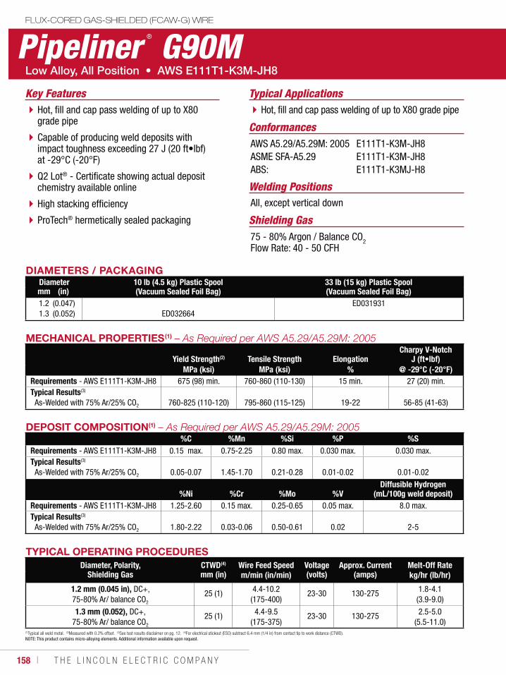
158 ı T H E L I N C O L N E L E C T R I C C O M P A N Y
Pipeliner ® G90MFLUX-CORED GAS-SHIELDED (FCAW-G) WIRE
Welding Positions
Typical Applications
All, except vertical down
Hot, fill and cap pass welding of up to X80 grade pipeHot, fill and cap pass welding of up to X80 grade pipe
Capable of producing weld deposits with impact toughness exceeding 27 J (20 ft•lbf) at -29°C (-20°F)
Q2 Lot® - Certificate showing actual depositchemistry available online
High stacking efficiency
ProTech® hermetically sealed packaging
Conformances
Shielding Gas75 - 80% Argon / Balance CO2Flow Rate: 40 - 50 CFH
Key Features
AWS A5.29/A5.29M: 2005ASME SFA-A5.29ABS:
E111T1-K3M-JH8E111T1-K3M-JH8E111T1-K3MJ-H8
DIAMETERS / PACKAGINGDiameter 10 lb (4.5 kg) Plastic Spool
(Vacuum Sealed Foil Bag)33 lb (15 kg) Plastic Spool(Vacuum Sealed Foil Bag)mm (in)
1.21.3
(0.047)(0.052) ED032664
ED031931
MECHANICAL PROPERTIES(1)
Yield Strength(2) Tensile Strength ElongationCharpy V-Notch
J (ft•lbf)MPa (ksi) MPa (ksi) % @ -29°C (-20°F)
Requirements - AWS E111T1-K3M-JH8 675 (98) min. 760-860 (110-130) 15 min. 27 (20) min.Typical Results(3)
As-Welded with 75% Ar/25% CO2 760-825 (110-120) 795-860 (115-125) 19-22 56-85 (41-63)
(1)Typical all weld metal. (2)Measured with 0.2% offset. (3)See test results disclaimer on pg. 12. (4)For electrical stickout (ESO) subtract 6.4 mm (1/4 in) from contact tip to work distance (CTWD). NOTE: This product contains micro-alloying elements. Additional information available upon request.
DEPOSIT COMPOSITION(1)
%C %Mn %Si %P %SRequirements - AWS E111T1-K3M-JH8 0.15 max. 0.75-2.25 0.80 max. 0.030 max. 0.030 max. Typical Results(3)
As-Welded with 75% Ar/25% CO2 0.05-0.07 1.45-1.70 0.21-0.28 0.01-0.02 0.01-0.02
%Ni %Cr %Mo %VDiffusible Hydrogen
(mL/100g weld deposit)Requirements - AWS E111T1-K3M-JH8 1.25-2.60 0.15 max. 0.25-0.65 0.05 max. 8.0 max.Typical Results(3)
As-Welded with 75% Ar/25% CO2 1.80-2.22 0.03-0.06 0.50-0.61 0.02 2-5
TYPICAL OPERATING PROCEDURESDiameter, Polarity,
Shielding GasCTWD(4)
mm (in)Wire Feed Speed Voltage
(volts)Approx. Current
(amps)Melt-Off Rate
m/min (in/min) kg/hr (lb/hr)
1.2 mm (0.045 in), DC+, 75-80% Ar/ balance CO2
25 (1) 4.4-10.2 (175-400)
23-30 130-275 1.8-4.1 (3.9-9.0)
1.3 mm (0.052), DC+, 75-80% Ar/ balance CO2
25 (1) 4.4-9.5 (175-375)
23-30 130-275 2.5-5.0 (5.5-11.0)
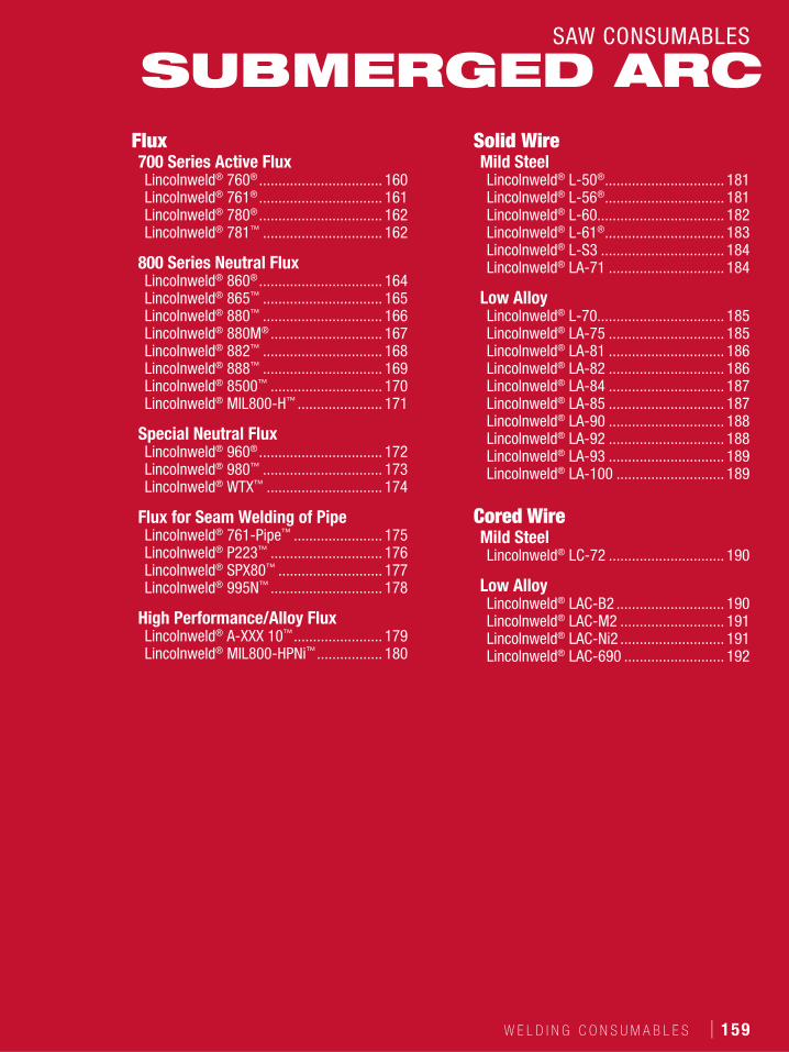
W E L D I N G C O N S U M A B L E S ı 159
SAW CONSUMABLES
Flux700 Series Active FluxLincolnweld® 760® ................................ 160Lincolnweld® 761® ................................ 161Lincolnweld® 780® ................................ 162Lincolnweld® 781™ ............................... 162
800 Series Neutral FluxLincolnweld® 860® ................................ 164Lincolnweld® 865™ ............................... 165Lincolnweld® 880™ ............................... 166Lincolnweld® 880M® ............................. 167Lincolnweld® 882™ ............................... 168Lincolnweld® 888™ ............................... 169Lincolnweld® 8500™ ............................. 170Lincolnweld® MIL800-H™ ...................... 171
Special Neutral FluxLincolnweld® 960® ................................ 172Lincolnweld® 980™ ............................... 173Lincolnweld® WTX™ .............................. 174
Flux for Seam Welding of PipeLincolnweld® 761-Pipe™ ....................... 175Lincolnweld® P223™ ............................. 176Lincolnweld® SPX80™ ........................... 177Lincolnweld® 995N™ ............................. 178
High Performance/Alloy FluxLincolnweld® A-XXX 10™ ....................... 179Lincolnweld® MIL800-HPNi™ ................. 180
Solid WireMild SteelLincolnweld® L-50® ............................... 181Lincolnweld® L-56® ............................... 181Lincolnweld® L-60................................. 182Lincolnweld® L-61® ............................... 183Lincolnweld® L-S3 ................................ 184Lincolnweld® LA-71 .............................. 184
Low AlloyLincolnweld® L-70................................. 185Lincolnweld® LA-75 .............................. 185Lincolnweld® LA-81 .............................. 186Lincolnweld® LA-82 .............................. 186Lincolnweld® LA-84 .............................. 187Lincolnweld® LA-85 .............................. 187Lincolnweld® LA-90 .............................. 188Lincolnweld® LA-92 .............................. 188Lincolnweld® LA-93 .............................. 189Lincolnweld® LA-100 ............................ 189
Cored WireMild SteelLincolnweld® LC-72 .............................. 190
Low AlloyLincolnweld® LAC-B2 ............................ 190Lincolnweld® LAC-M2 ........................... 191Lincolnweld® LAC-Ni2 ........................... 191Lincolnweld® LAC-690 .......................... 192
SUBMERGED ARC
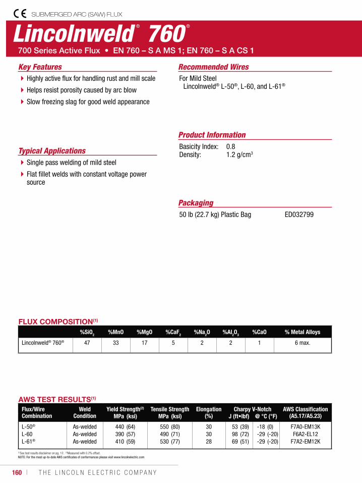
160 ı T H E L I N C O L N E L E C T R I C C O M P A N Y
Lincolnweld ® 760 ®
SUBMERGED ARC (SAW) FLUX
Recommended Wires
Typical Applications
For Mild Steel Lincolnweld® L-50®, L-60, and L-61®
Single pass welding of mild steel
Flat fillet welds with constant voltage power source
Highly active flux for handling rust and mill scale
Helps resist porosity caused by arc blow
Slow freezing slag for good weld appearance
Product InformationBasicity Index: 0.8Density: 1.2 g/cm3
Key Features
FLUX COMPOSITION(1)
%SiO2 %MnO %MgO %CaF2 %Na2O %Al2O3 %CaO % Metal Alloys
Lincolnweld® 760® 47 33 17 5 2 2 1 6 max.
(1)See test results disclaimer on pg. 12. (2)Measured with 0.2% offset. NOTE: For the most up-to-date AWS certificates of conformances please visit www.lincolnelectric.com
AWS TEST RESULTS(1)
Flux/Wire Combination
Weld Condition
Yield Strength(2) Tensile Strength Elongation (%)
Charpy V-Notch AWS Classification (A5.17/A5.23)MPa (ksi) MPa (ksi) J (ft•lbf) @ °C (°F)
L-50®
L-60L-61®
As-weldedAs-weldedAs-welded
440390410
(64)(57)(59)
550490530
(80)(71)(77)
303028
539869
(39)(72)(51)
-18-29-29
(0)(-20)(-20)
F7A0-EM13KF6A2-EL12
F7A2-EM12K
Packaging50 lb (22.7 kg) Plastic Bag ED032799
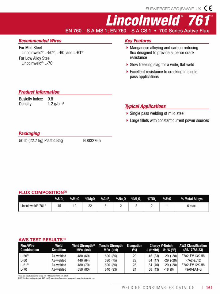
W E L D I N G C O N S U M A B L E S C A T A L O G ı 161
SUBMERGED ARC (SAW) FLUX
(1)See test results disclaimer on pg. 12. (2)Measured with 0.2% offset. NOTE: For the most up-to-date AWS certificates of conformances please visit www.lincolnelectric.com
Lincolnweld ® 761 ®
Recommended Wires
Typical Applications
For Mild Steel Lincolnweld® L-50®, L-60, and L-61®
For Low Alloy Steel Lincolnweld® L-70
Single pass welding of mild steel
Large fillets with constant current power sources
Manganese alloying and carbon reducing flux designed to provide superior crack resistance
Slow freezing slag for a wide, flat weld
Excellent resistance to cracking in single pass applications
Product InformationBasicity Index: 0.8Density: 1.2 g/cm3
Key Features
FLUX COMPOSITION(1)
%SiO2 %MnO %MgO %CaF2 %Na2O %Al2O3 %TiO2 %FeO % Metal Alloys
Lincolnweld® 761® 45 19 22 5 2 2 2 1 6 max.
AWS TEST RESULTS(1)
Flux/Wire Combination
Weld Condition
Yield Strength(2) Tensile Strength Elongation (%)
Charpy V-Notch AWS Classification (A5.17/A5.23)MPa (ksi) MPa (ksi) J (ft•lbf) @ °C (°F)
L-50®
L-60L-61®
L-70
As-weldedAs-weldedAs-weldedAs-welded
480440480550
(69)(64)(70)(80)
590530590640
(85)(75)(85)(93)
29292824
45645458
(33)(47)(40)(43)
-29-29-29-18
(-20)(-20)(-20)(0)
F7A2-EM13K-H8F7A2-EL12
F7A2-EM12K-H8F9A0-EA1-G
Packaging50 lb (22.7 kg) Plastic Bag ED032765

162 ı T H E L I N C O L N E L E C T R I C C O M P A N Y
Lincolnweld ® 780 ®
SUBMERGED ARC (SAW) FLUX
Recommended Wires
Typical Applications
For Mild Steel Lincolnweld® L-50®, L-60 and L-61®
Single pass welding of mild steel
Roundabouts with minimal spillage
Horizontal position welding
Industry standard for submerged arc welding applications
Fast freezing slag for easy removal and minimized spilling on circumferential welds
When paired with Lincolnweld® L-61® it is recommended for up to three pass welding applications
Excellent bead shape and slag removal
Good resistance to moisture contamination for reduced porosity
Product InformationBasicity Index: 0.7Density: 1.4 g/cm3
Key Features
FLUX COMPOSITION(1)
%SiO2 %MnO %MgO %CaF2 %Na2O %Al2O3 %CaO %TiO2 % Metal Alloys
Lincolnweld® 780® 9 16 2 11 2 45 1 9 6 max.
AWS TEST RESULTS(1)
Flux/Wire Combination
Weld Condition
Yield Strength(2) Tensile Strength Elongation (%)
Charpy V-Notch AWS Classification (A5.17/A5.23)MPa (ksi) MPa (ksi) J (ft•lbf) @ °C (°F)
L-50®
L-60L-61®
As-weldedAs-weldedAs-welded
520440530
(75)(64)(77)
600520600
(87)(76)(87)
273027
658846
(48)(65)(34)
-18-18-29
(0)(0)(-20)
F7A0-EM13KF7A0-EL12-H8
F7A2-EM12K-H8
(1)See test results disclaimer on pg. 12. (2)Measured with 0.2% offset. NOTE: For the most up-to-date AWS certificates of conformances please visit www.lincolnelectric.com
Packaging50 lb (22.7 kg) Bag550 lb (249.5 kg) Steel Drum3000 lb (1361 kg) Bulk Bag
ED019586ED032007ED033188
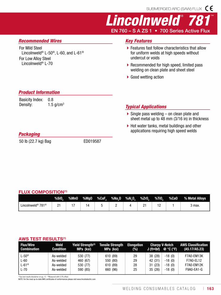
W E L D I N G C O N S U M A B L E S C A T A L O G ı 163
Lincolnweld ® 781™
SUBMERGED ARC (SAW) FLUX
Recommended Wires
Typical Applications
For Mild Steel Lincolnweld® L-50®, L-60, and L-61®
For Low Alloy Steel Lincolnweld® L-70
Single pass welding – on clean plate and sheet metal up to 48 mm (3/16 in) in thickness
Hot water tanks, metal buildings and other applications requiring high speed welds
Features fast follow characteristics that allow for uniform welds at high speeds without undercut or voids
Recommended for high speed, limited pass welding on clean plate and sheet steel
Good wetting action
Product InformationBasicity Index: 0.8Density: 1.5 g/cm3
Key Features
FLUX COMPOSITION(1)
%SiO2 %MnO %MgO %CaF2 %Na2O %Al2O3 %ZrO2 %TiO2 %CaO % Metal Alloys
Lincolnweld® 781® 21 17 14 5 2 4 21 12 1 3 max.
AWS TEST RESULTS(1)
Flux/Wire Combination
Weld Condition
Yield Strength(2) Tensile Strength Elongation (%)
Charpy V-Notch AWS Classification (A5.17/A5.23)MPa (ksi) MPa (ksi) J (ft•lbf) @ °C (°F)
L-50®
L-60L-61®
L-70
As-weldedAs-weldedAs-weldedAs-welded
530460530590
(77)(67)(77)(85)
610550610660
(89)(80)(89)(96)
29292825
38423135
(28)(31)(23)(26)
-18-18-18-18
(0)(0)(0)(0)
F7A0-EM13KF7A0-EL12
F7A0-EM12KF9A0-EA1-G
(1)See test results disclaimer on pg. 12. (2)Measured with 0.2% offset. NOTE: For the most up-to-date AWS certificates of conformances please visit www.lincolnelectric.com
Packaging50 lb (22.7 kg) Bag ED019587
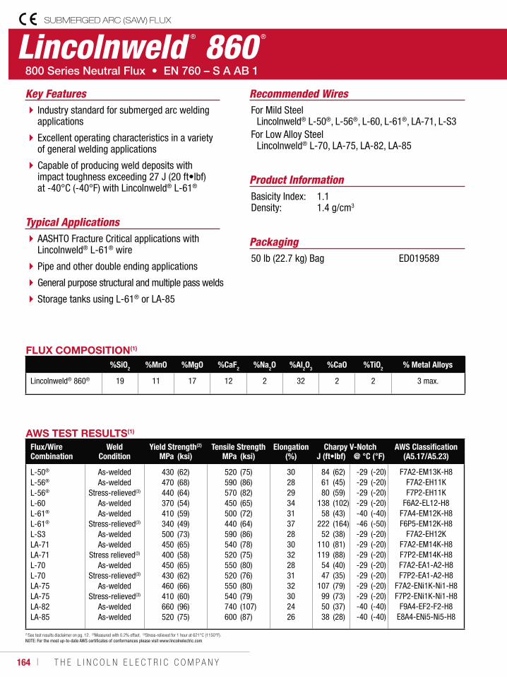
164 ı T H E L I N C O L N E L E C T R I C C O M P A N Y
Lincolnweld ® 860 ®
SUBMERGED ARC (SAW) FLUX
Recommended Wires
Typical Applications
For Mild Steel Lincolnweld® L-50®, L-56®, L-60, L-61®, LA-71, L-S3For Low Alloy Steel Lincolnweld® L-70, LA-75, LA-82, LA-85
AASHTO Fracture Critical applications with Lincolnweld® L-61® wire
Pipe and other double ending applications
General purpose structural and multiple pass welds
Storage tanks using L-61® or LA-85
Industry standard for submerged arc welding applications
Excellent operating characteristics in a variety of general welding applications
Capable of producing weld deposits with impact toughness exceeding 27 J (20 ft•lbf) at -40°C (-40°F) with Lincolnweld® L-61®
Product InformationBasicity Index: 1.1Density: 1.4 g/cm3
Key Features
Packaging50 lb (22.7 kg) Bag ED019589
(1)See test results disclaimer on pg. 12. (2)Measured with 0.2% offset. (3)Stress-relieved for 1 hour at 621°C (1150°F). NOTE: For the most up-to-date AWS certificates of conformances please visit www.lincolnelectric.com
AWS TEST RESULTS(1)
Flux/Wire Combination
Weld Condition
Yield Strength(2) Tensile Strength Elongation (%)
Charpy V-Notch AWS Classification (A5.17/A5.23)MPa (ksi) MPa (ksi) J (ft•lbf) @ °C (°F)
L-50®
L-56®
L-56®
L-60L-61®
L-61®
L-S3LA-71LA-71L-70L-70LA-75LA-75LA-82LA-85
As-weldedAs-welded
Stress-relieved(3)
As-weldedAs-welded
Stress-relieved(3)
As-weldedAs-welded
Stress relieved(3)
As-weldedStress-relieved(3)
As-weldedStress-relieved(3)
As-weldedAs-welded
430470440370410340500450400450430460410660520
(62)(68)(64)(54)(59)(49)(73)(65)(58)(65)(62)(66)(60)(96)(75)
520590570450500440590540520550520550540740600
(75)(86)(82)(65)(72)(64)(86)(78)(75)(80)(76)(80)(79)(107)(87)
302829343137283032283132302426
846180
13858
22252
110119
5447
107995038
(62)(45)(59)(102)(43)(164)(38)(81)(88)(40)(35)(79)(73)(37)(28)
-29-29-29-29-40-46-29-29-29-29-29-29-29-40-40
(-20)(-20)(-20)(-20)(-40)(-50)(-20)(-20)(-20)(-20)(-20)(-20)(-20)(-40)(-40)
F7A2-EM13K-H8F7A2-EH11KF7P2-EH11K
F6A2-EL12-H8F7A4-EM12K-H8F6P5-EM12K-H8
F7A2-EH12KF7A2-EM14K-H8F7P2-EM14K-H8F7A2-EA1-A2-H8F7P2-EA1-A2-H8
F7A2-ENi1K-Ni1-H8F7P2-ENi1K-Ni1-H8
F9A4-EF2-F2-H8E8A4-ENi5-Ni5-H8
FLUX COMPOSITION(1)
%SiO2 %MnO %MgO %CaF2 %Na2O %Al2O3 %CaO %TiO2 % Metal Alloys
Lincolnweld® 860® 19 11 17 12 2 32 2 2 3 max.
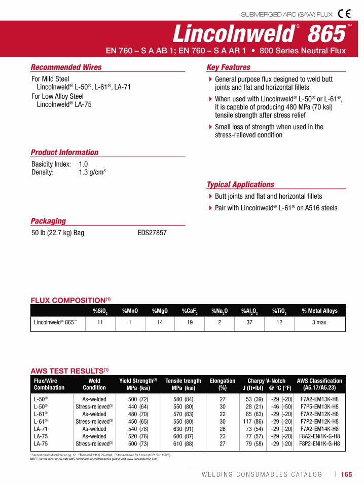
W E L D I N G C O N S U M A B L E S C A T A L O G ı 165
Lincolnweld ® 865 ™
SUBMERGED ARC (SAW) FLUX
Recommended Wires
Typical Applications
For Mild Steel Lincolnweld® L-50®, L-61®, LA-71For Low Alloy Steel Lincolnweld® LA-75
Butt joints and flat and horizontal fillets
Pair with Lincolnweld® L-61® on A516 steels
General purpose flux designed to weld butt joints and flat and horizontal fillets
When used with Lincolnweld® L-50® or L-61®, it is capable of producing 480 MPa (70 ksi) tensile strength after stress relief
Small loss of strength when used in the stress-relieved condition
Product InformationBasicity Index: 1.0Density: 1.3 g/cm3
Key Features
FLUX COMPOSITION(1)
%SiO2 %MnO %MgO %CaF2 %Na2O %Al2O3 %TiO2 % Metal Alloys
Lincolnweld® 865™ 11 1 14 19 2 37 12 3 max.
AWS TEST RESULTS(1)
Flux/Wire Combination
Weld Condition
Yield Strength(2) Tensile trength Elongation (%)
Charpy V-Notch AWS Classification (A5.17/A5.23)MPa (ksi) MPa (ksi) J (ft•lbf) @ °C (°F)
L-50®
L-50®
L-61®
L-61®
LA-71LA-75LA-75
As-weldedStress-relieved(3)
As-weldedStress-relieved(3)
As-weldedAs-welded
Stress-relieved(3)
500440480450540520500
(72)(64)(70)(65)(78)(76)(73)
580550570550630600610
(84)(80)(83)(80)(91)(87)(88)
27302230262327
532885
117737779
(39)(21)(63)(86)(54)(57)(58)
-29-46-29-29-29-29-29
(-20)(-50)(-20)(-20)(-20)(-20)(-20)
F7A2-EM13K-H8F7P5-EM13K-H8F7A2-EM12K-H8F7P2-EM12K-H8F7A2-EM14K-H8F8A2-ENi1K-G-H8F8P2-ENi1K-G-H8
(1)See test results disclaimer on pg. 12. (2)Measured with 0.2% offset. (3)Stress-relieved for 1 hour at 621°C (1150°F).NOTE: For the most up-to-date AWS certificates of conformances please visit www.lincolnelectric.com
Packaging50 lb (22.7 kg) Bag EDS27857
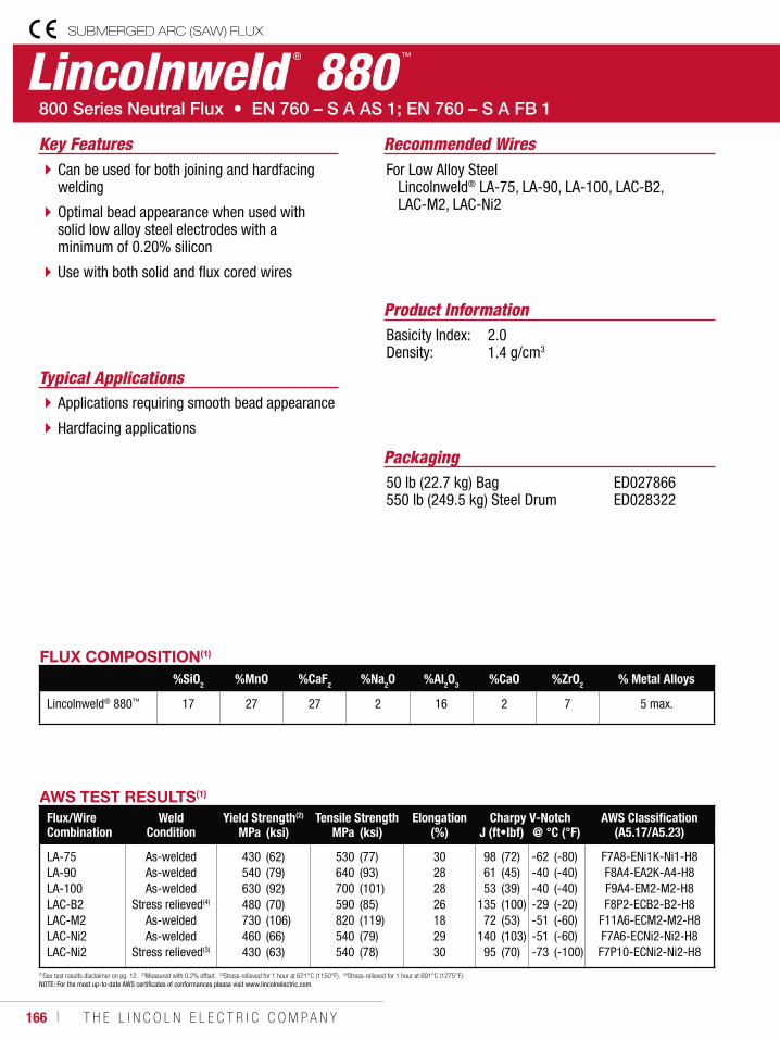
166 ı T H E L I N C O L N E L E C T R I C C O M P A N Y
SUBMERGED ARC (SAW) FLUX
Lincolnweld ® 880 ™
Recommended Wires
Typical Applications
For Low Alloy Steel Lincolnweld® LA-75, LA-90, LA-100, LAC-B2, LAC-M2, LAC-Ni2
Applications requiring smooth bead appearance
Hardfacing applications
Can be used for both joining and hardfacing welding
Optimal bead appearance when used with solid low alloy steel electrodes with a minimum of 0.20% silicon
Use with both solid and flux cored wires
Product InformationBasicity Index: 2.0Density: 1.4 g/cm3
Key Features
Packaging50 lb (22.7 kg) Bag 550 lb (249.5 kg) Steel Drum
ED027866 ED028322
FLUX COMPOSITION(1)
%SiO2 %MnO %CaF2 %Na2O %Al2O3 %CaO %ZrO2 % Metal Alloys
Lincolnweld® 880™ 17 27 27 2 16 2 7 5 max.
AWS TEST RESULTS(1)
Flux/Wire Combination
Weld Condition
Yield Strength(2) Tensile Strength Elongation (%)
Charpy V-Notch AWS Classification (A5.17/A5.23)MPa (ksi) MPa (ksi) J (ft•lbf) @ °C (°F)
LA-75LA-90LA-100LAC-B2LAC-M2LAC-Ni2LAC-Ni2
As-weldedAs-weldedAs-welded
Stress relieved(4)
As-weldedAs-welded
Stress relieved(3)
430540630480730460430
(62)(79)(92)(70)(106)(66)(63)
530640700590820540540
(77)(93)(101)(85)(119)(79)(78)
30282826182930
986153
13572
14095
(72)(45)(39)(100)(53)(103)(70)
-62-40-40-29-51-51-73
(-80)(-40)(-40)(-20)(-60)(-60) (-100)
F7A8-ENi1K-Ni1-H8F8A4-EA2K-A4-H8F9A4-EM2-M2-H8F8P2-ECB2-B2-H8
F11A6-ECM2-M2-H8F7A6-ECNi2-Ni2-H8F7P10-ECNi2-Ni2-H8
(1)See test results disclaimer on pg. 12. (2)Measured with 0.2% offset. (3)Stress-relieved for 1 hour at 621°C (1150°F). (4)Stress-relieved for 1 hour at 691°C (1275°F).NOTE: For the most up-to-date AWS certificates of conformances please visit www.lincolnelectric.com
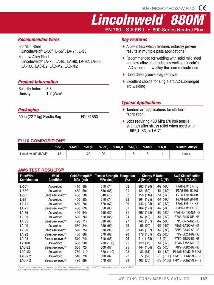
W E L D I N G C O N S U M A B L E S C A T A L O G ı 167
Lincolnweld ® 880M ®
SUBMERGED ARC (SAW) FLUX
Recommended Wires
Typical Applications
For Mild Steel Lincolnweld® L-50®, L-56®, LA-71, L-S3For Low Alloy Steel Lincolnweld® LA-75, LA-85, LA-90, LA-92, LA-93, LA-100, LAC-B2, LAC-M2, LAC-Ni2
Tandem arc applications for offshore fabrication
Jobs requiring 480 MPa (70 ksi) tensile strength after stress relief when used with L-56®, L-S3, or LA-71
A basic flux which features industry proven results in multiple pass applications
Recommended for welding with solid mild steel and low alloy electrodes, as well as Lincoln’s LAC series of low alloy flux-cored electrodes
Good deep groove slag removal
Excellent choice for single arc AC submerged arc welding
Product InformationBasicity Index: 3.3Density: 1.2 g/cm3
Key Features
Packaging50 lb (22.7 kg) Plastic Bag ED031853
FLUX COMPOSITION(1)
%SiO2 %MnO %MgO %CaF2 %Na2O %Al2O3 %CaO %K2O % Metal Alloys
Lincolnweld® 880M® 12 1 29 29 1 18 8 1 1 max.
AWS TEST RESULTS(1)
Flux/Wire Combination
Weld Condition
Yield Strength(2) Tensile Strength Elongation (%)
Charpy V-Notch AWS Classification (A5.17/A5.23)MPa (ksi) MPa (ksi) J (ft•lbf) @ °C (°F)
L-50®
L-56®
L-56®
L-S3LA-71LA-71LA-75LA-85LA-85LA-90LA-90LA-92LA-93LA-100LAC-B2LAC-M2LAC-Ni2LAC-Ni2
As-weldedAs-welded
Stress-relieved(3)
As-weldedAs-welded
Stress-relieved(3)
As-weldedAs-welded
Stress-relieved(3)
As-weldedStress-relieved(3)
Stress-relieved(4)
Stress-relieved(4)
As-weldedStress-relieved(4)
As-weldedAs-welded
Stress-relieved(3)
410480400400480430440520490580520460510680500760510480
(59)(69)(58)(58)(70)(63)(64)(76)(71)(84)(75)(66)(74)(98)(72)(110)(73)(69)
510580540510570550550610590680630570610730600820600570
(74)(85)(78)(74)(82)(80)(80)(88)(85)(99)(91)(82)(88)(106)(87)(119)(87)(83)
323132322931312427262828262525232228
263121158264143164167
57145
68145178214129144
8377
103
(194)(89)(116)(195)(105)(121)(123)(42)(107)(50)(107)(131)(158)(95)(106)(61)(57)(76)
-62-51-51-51-62-62-62-51-62-51-62-29-18-51-29-51-73-73
(-80)(-60)(-60)(-60)(-80)(-80)(-80)(-60)(-80)(-60)(-80)(-20)(0)(-60)(-20)(-60)(-100)(-100)
F7A8-EM13K-H8F7A6-EH11K-H8F7P6-EH11K-H8F7A6-EH12K-H8F7A8-EM14K-H8F7P8-EM14K-H8
F7A8-ENi1K-Ni1-H8F7A6-ENi5-Ni5-H8F7P8-ENi5-Ni5-H8F9A6-EA3K-A3-H8F8P8-EA3K-A3-H8F7P2-EB2R-B2-H8F7P0-EB3R-B3-H8F9A6-EM2-M2-H8F8P2-ECB2-B2-H8
F11A6-ECM2-M2-H8F7A10-ECNi2-Ni2-H8F7P10-ECNi2-Ni2-H8
(1)See test results disclaimer on pg. 12. (2)Measured with 0.2% offset. (3)Stress-relieved for 1 hour at 621°C (1150°F). (4)Stress-relieved for 1 hour at 691°C (1275°F).NOTE: For the most up-to-date AWS certificates of conformances please visit www.lincolnelectric.com
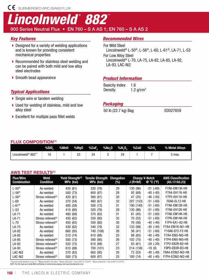
168 ı T H E L I N C O L N E L E C T R I C C O M P A N Y
Lincolnweld ® 882 ™
SUBMERGED ARC (SAW) FLUX
Recommended Wires
Typical Applications
For Mild Steel Lincolnweld® L-50®, L-56®, L-60, L-61®, LA-71, L-S3For Low Alloy Steel Lincolnweld® L-70, LA-75, LA-82, LA-85, LA-92, LA-93, LAC-Ni2
Single wire or tandem welding
Used for welding of stainless, mild and low alloy steel
Excellent for multiple pass fillet welds
Designed for a variety of welding applications and is known for providing consistent mechanical properties
Recommended for stainless steel welding and can be paired with both mild and low alloy steel electrodes
Smooth bead appearance Product InformationBasicity Index: 1.6Density: 1.2 g/cm3
Key Features
Packaging50 lb (22.7 kg) Bag ED027859
FLUX COMPOSITION(1)
%SiO2 %MnO %MgO %CaF2 %Na2O %Al2O3 %CaO %ZrO2 % Metal Alloys
Lincolnweld® 882™ 16 1 22 24 2 24 1 7 3 max.
AWS TEST RESULTS(1)
Flux/Wire Combination
Weld Condition
Yield Strength(2) Tensile Strength Elongation (%)
Charpy V-Notch AWS Classification (A5.17/A5.23)MPa (ksi) MPa (ksi) J (ft•lbf) @ °C (°F)
L-50®
L-56®
L-56®
L-60L-61®
L-S3LA-71LA-71L-70LA-75LA-82LA-85LA-85LA-92LA-93LAC-Ni2LAC-Ni2
As-weldedAs-welded
Stress-relieved(3)
As-weldedAs-weldedAs-weldedAs-welded
Stress-relieved(3)
Stress-relieved(3)
As-weldedAs-weldedAs-welded
Stress-relieved(3)
Stress-relieved(4)
Stress-relieved(4)
As-weldedStress-relieved(3)
420500420370400410480430450430660510500520610570500
(61)(73)(61)(54)(58)(60)(69)(62)(65)(62)(95)(74)(73)(75)(88)(83)(73)
520600560460500520570550550540740610590610700660600
(76)(87)(81)(67)(72)(76)(82)(80)(80)(79)(108)(88)(86)(89)(101)(95)(87)
2928303231283132303226252627232025
1309247
207190130
617076
1335688
10283
21472
100
(96)(68)(35)(153)(140)(96)(45)(52)(56)(98)(41)(65)(75)(61)(158)(53)(74)
-51-40-46-51-51-51-51-51-40-40-51-40-40-29-18-40-40
(-60)(-40)(-50)(-60)(-60)(-60)(-60)(-60)(-40)(-40)(-60)(-40)(-40)(-20)(0)(-40)(-40)
F7A6-EM13K-H8F7A4-EH11K-H8F7P5-EH11K-H8F6A6-EL12-H8
F7A6-EM12K-H8F7A6-EH12K-H8F7A6-EM14K-H8F7P6-EM14K-H8F7P4-EA1-A2-H8
F7A4-ENi1K-Ni1-H8F10A6-EF2-F2-H8F7A4-ENi5-Ni5-H8F7P4-ENi5-Ni5-H8F7P2-EB2R-B2-H8F9P0-EB3R-B3-H8
F8A4-ECNi2-Ni2-H8F7P4-ECNi2-Ni2-H8
(1)See test results disclaimer on pg. 12. (2)Measured with 0.2% offset. (3)Stress-relieved for 1 hour at 621°C (1150°F). (4)Stress-relieved for 1 hour at 691°C (1275°F).NOTE: For the most up-to-date AWS certificates of conformances please visit www.lincolnelectric.com
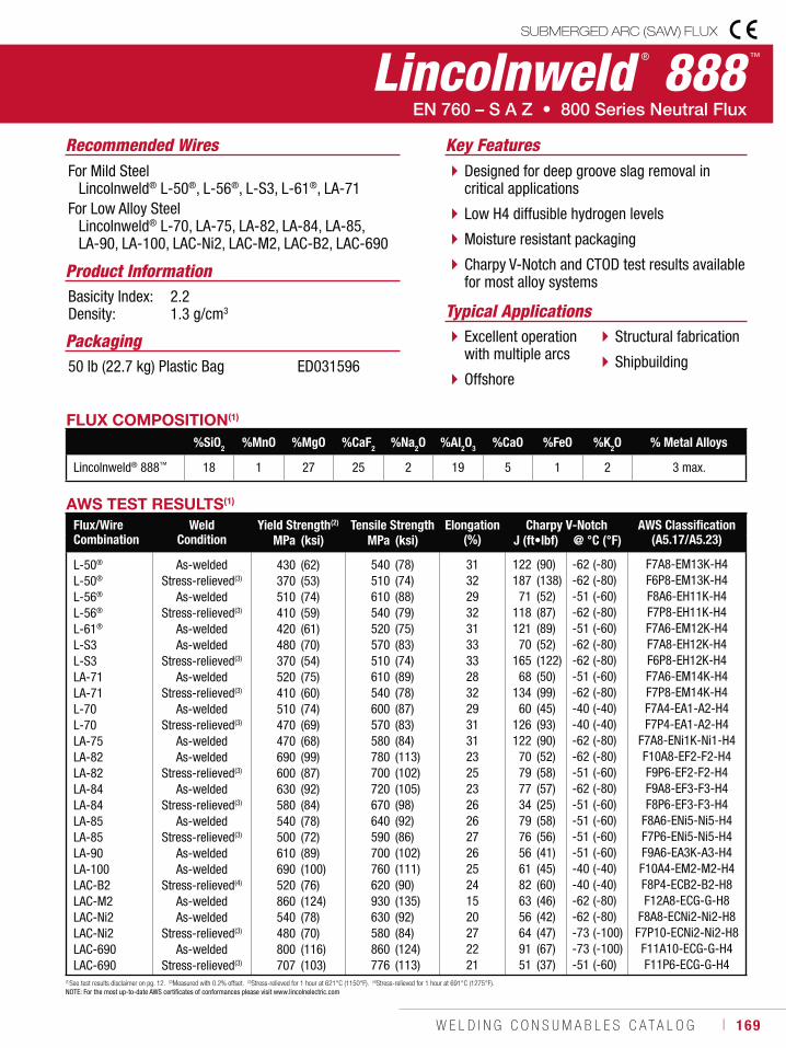
W E L D I N G C O N S U M A B L E S C A T A L O G ı 169
Lincolnweld ® 888 ™
SUBMERGED ARC (SAW) FLUX
Typical ApplicationsExcellent operation with multiple arcs
Offshore
Structural fabrication
Shipbuilding
Designed for deep groove slag removal in critical applications
Low H4 diffusible hydrogen levels
Moisture resistant packaging
Charpy V-Notch and CTOD test results available for most alloy systems
Recommended WiresFor Mild Steel Lincolnweld® L-50®, L-56®, L-S3, L-61®, LA-71For Low Alloy Steel Lincolnweld® L-70, LA-75, LA-82, LA-84, LA-85, LA-90, LA-100, LAC-Ni2, LAC-M2, LAC-B2, LAC-690
Product InformationBasicity Index: 2.2Density: 1.3 g/cm3
Key Features
Packaging50 lb (22.7 kg) Plastic Bag ED031596
FLUX COMPOSITION(1)
%SiO2 %MnO %MgO %CaF2 %Na2O %Al2O3 %CaO %FeO %K2O % Metal Alloys
Lincolnweld® 888™ 18 1 27 25 2 19 5 1 2 3 max.
AWS TEST RESULTS(1)
Flux/Wire Combination
Weld Condition
Yield Strength(2) Tensile Strength Elongation (%)
Charpy V-Notch AWS Classification (A5.17/A5.23)MPa (ksi) MPa (ksi) J (ft•lbf) @ °C (°F)
L-50®
L-50®
L-56®
L-56®
L-61®
L-S3L-S3LA-71LA-71L-70L-70LA-75LA-82LA-82LA-84LA-84LA-85LA-85LA-90LA-100LAC-B2LAC-M2LAC-Ni2LAC-Ni2LAC-690LAC-690
As-weldedStress-relieved(3)
As-weldedStress-relieved(3)
As-weldedAs-welded
Stress-relieved(3)
As-weldedStress-relieved(3)
As-weldedStress-relieved(3)
As-weldedAs-welded
Stress-relieved(3)
As-weldedStress-relieved(3)
As-weldedStress-relieved(3)
As-weldedAs-welded
Stress-relieved(4)
As-weldedAs-welded
Stress-relieved(3)
As-weldedStress-relieved(3)
430370510410420480370520410510470470690600630580540500610690520860540480800707
(62)(53)(74)(59)(61)(70)(54)(75)(60)(74)(69)(68)(99)(87)(92)(84)(78)(72)(89)(100)(76)(124)(78)(70)(116)(103)
540510610540520570510610540600570580780700720670640590700760620930630580860776
(78)(74)(88)(79)(75)(83)(74)(89)(78)(87)(83)(84)(113)(102)(105)(98)(92)(86)(102)(111)(90)(135)(92)(84)(124)(113)
3132293231333328322931312325232626272625241520272221
122187
71118121
70165
68134
60126122
7079773479765661826356649151
(90)(138)(52)(87)(89)(52)(122)(50)(99)(45)(93)(90)(52)(58)(57)(25)(58)(56)(41)(45)(60)(46)(42)(47)(67)(37)
-62-62-51-62-51-62-62-51-62-40-40-62-62-51-62-51-51-51-51-40-40-62-62-73-73-51
(-80)(-80)(-60)(-80)(-60)(-80)(-80)(-60)(-80)(-40)(-40)(-80)(-80)(-60)(-80)(-60)(-60)(-60)(-60)(-40)(-40)(-80)(-80)(-100)(-100)(-60)
F7A8-EM13K-H4F6P8-EM13K-H4F8A6-EH11K-H4F7P8-EH11K-H4F7A6-EM12K-H4F7A8-EH12K-H4F6P8-EH12K-H4F7A6-EM14K-H4F7P8-EM14K-H4F7A4-EA1-A2-H4F7P4-EA1-A2-H4
F7A8-ENi1K-Ni1-H4F10A8-EF2-F2-H4F9P6-EF2-F2-H4F9A8-EF3-F3-H4F8P6-EF3-F3-H4
F8A6-ENi5-Ni5-H4F7P6-ENi5-Ni5-H4F9A6-EA3K-A3-H4F10A4-EM2-M2-H4F8P4-ECB2-B2-H8F12A8-ECG-G-H8
F8A8-ECNi2-Ni2-H8F7P10-ECNi2-Ni2-H8F11A10-ECG-G-H4 F11P6-ECG-G-H4
(1)See test results disclaimer on pg. 12. (2)Measured with 0.2% offset. (3)Stress-relieved for 1 hour at 621°C (1150°F). (4)Stress-relieved for 1 hour at 691°C (1275°F).NOTE: For the most up-to-date AWS certificates of conformances please visit www.lincolnelectric.com
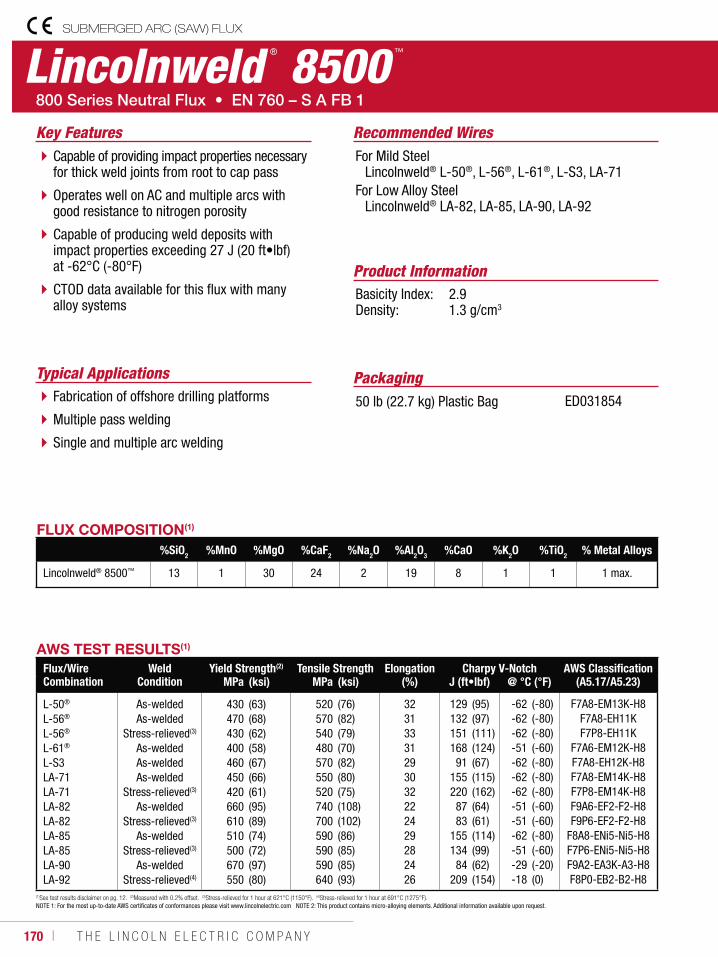
170 ı T H E L I N C O L N E L E C T R I C C O M P A N Y
Lincolnweld ® 8500 ™
SUBMERGED ARC (SAW) FLUX
Recommended Wires
Typical Applications
For Mild Steel Lincolnweld® L-50®, L-56®, L-61®, L-S3, LA-71For Low Alloy Steel Lincolnweld® LA-82, LA-85, LA-90, LA-92
Fabrication of offshore drilling platforms
Multiple pass welding
Single and multiple arc welding
Capable of providing impact properties necessary for thick weld joints from root to cap pass
Operates well on AC and multiple arcs with good resistance to nitrogen porosity
Capable of producing weld deposits with impact properties exceeding 27 J (20 ft•lbf) at -62°C (-80°F)
CTOD data available for this flux with many alloy systems
Product InformationBasicity Index: 2.9Density: 1.3 g/cm3
Key Features
Packaging50 lb (22.7 kg) Plastic Bag ED031854
AWS TEST RESULTS(1)
Flux/Wire Combination
Weld Condition
Yield Strength(2) Tensile Strength Elongation (%)
Charpy V-Notch AWS Classification (A5.17/A5.23)MPa (ksi) MPa (ksi) J (ft•lbf) @ °C (°F)
L-50®
L-56®
L-56®
L-61®
L-S3LA-71LA-71LA-82LA-82LA-85LA-85LA-90LA-92
As-weldedAs-welded
Stress-relieved(3)
As-weldedAs-weldedAs-welded
Stress-relieved(3)
As-weldedStress-relieved(3)
As-weldedStress-relieved(3)
As-weldedStress-relieved(4)
430470430400460450420660610510500670550
(63)(68)(62)(58)(67)(66)(61)(95)(89)(74)(72)(97)(80)
520570540480570550520740700590590590640
(76)(82)(79)(70)(82)(80)(75)(108)(102)(86)(85)(85)(93)
32313331293032222429282426
129132151168
91155220
8783
155134
84209
(95)(97)(111)(124)(67)(115)(162)(64)(61)(114)(99)(62)(154)
-62-62-62-51-62-62-62-51-51-62-51-29-18
(-80)(-80)(-80)(-60)(-80)(-80)(-80)(-60)(-60)(-80)(-60)(-20)(0)
F7A8-EM13K-H8F7A8-EH11KF7P8-EH11K
F7A6-EM12K-H8F7A8-EH12K-H8F7A8-EM14K-H8F7P8-EM14K-H8F9A6-EF2-F2-H8F9P6-EF2-F2-H8
F8A8-ENi5-Ni5-H8F7P6-ENi5-Ni5-H8F9A2-EA3K-A3-H8F8P0-EB2-B2-H8
(1)See test results disclaimer on pg. 12. (2)Measured with 0.2% offset. (3)Stress-relieved for 1 hour at 621°C (1150°F). (4)Stress-relieved for 1 hour at 691°C (1275°F).NOTE 1: For the most up-to-date AWS certificates of conformances please visit www.lincolnelectric.com NOTE 2: This product contains micro-alloying elements. Additional information available upon request.
FLUX COMPOSITION(1)
%SiO2 %MnO %MgO %CaF2 %Na2O %Al2O3 %CaO %K2O %TiO2 % Metal Alloys
Lincolnweld® 8500™ 13 1 30 24 2 19 8 1 1 1 max.
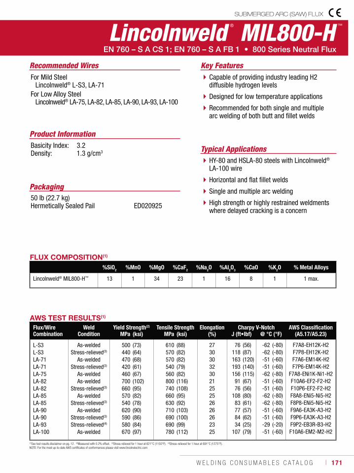
W E L D I N G C O N S U M A B L E S C A T A L O G ı 171
Lincolnweld ® MIL800-H ™
SUBMERGED ARC (SAW) FLUX
Recommended Wires
Typical Applications
For Mild Steel Lincolnweld® L-S3, LA-71For Low Alloy Steel Lincolnweld® LA-75, LA-82, LA-85, LA-90, LA-93, LA-100
HY-80 and HSLA-80 steels with Lincolnweld® LA-100 wire
Horizontal and flat fillet welds
Single and multiple arc welding
High strength or highly restrained weldments where delayed cracking is a concern
Capable of providing industry leading H2 diffusible hydrogen levels
Designed for low temperature applications
Recommended for both single and multiple arc welding of both butt and fillet welds
Product InformationBasicity Index: 3.2Density: 1.3 g/cm3
Key Features
Packaging50 lb (22.7 kg) Hermetically Sealed Pail ED020925
AWS TEST RESULTS(1)
Flux/Wire Combination
Weld Condition
Yield Strength(2) Tensile Strength Elongation (%)
Charpy V-Notch AWS Classification (A5.17/A5.23)MPa (ksi) MPa (ksi) J (ft•lbf) @ °C (°F)
L-S3L-S3LA-71LA-71LA-75LA-82LA-82LA-85LA-85LA-90LA-90LA-93LA-100
As-weldedStress-relieved(3)
As-weldedStress-relieved(3)
As-weldedAs-welded
Stress-relieved(3)
As-weldedStress-relieved(3)
As-weldedStress-relieved(3)
Stress-relieved(4)
As-welded
500440470420460700660570540620590580670
(73)(64)(68)(61)(67)(102)(95)(82)(78)(90)(86)(84)(97)
610570570540560800740660630710690690780
(88)(82)(82)(79)(82)(116)(108)(95)(92)(103)(100)(99)(112)
27303032302125252626262325
76118163193156
9176
10883778434
107
(56)(87)(120)(140)(115)(67)(56)(80)(61)(57)(62)(25)(79)
-62-62-51-51-62-51-51-62-62-51-51-29-51
(-80)(-80)(-60)(-60)(-80)(-60)(-60)(-80)(-80)(-60)(-60)(-20)(-60)
F7A8-EH12K-H2F7P8-EH12K-H2F7A6-EM14K-H2F7P6-EM14K-H2
F7A8-ENi1K-Ni1-H2F10A6-EF2-F2-H2F10P6-EF2-F2-H2F8A8-ENi5-Ni5-H2F8P8-ENi5-Ni5-H2F9A6-EA3K-A3-H2F9P6-EA3K-A3-H2F9P2-EB3R-B3-H2F10A6-EM2-M2-H2
(1)See test results disclaimer on pg. 12. (2)Measured with 0.2% offset. (3)Stress-relieved for 1 hour at 621°C (1150°F). (4)Stress-relieved for 1 hour at 691°C (1275°F).NOTE: For the most up-to-date AWS certificates of conformances please visit www.lincolnelectric.com
FLUX COMPOSITION(1)
%SiO2 %MnO %MgO %CaF2 %Na2O %Al2O3 %CaO %K2O % Metal Alloys
Lincolnweld® MIL800-H™ 13 1 34 23 1 16 8 1 1 max.
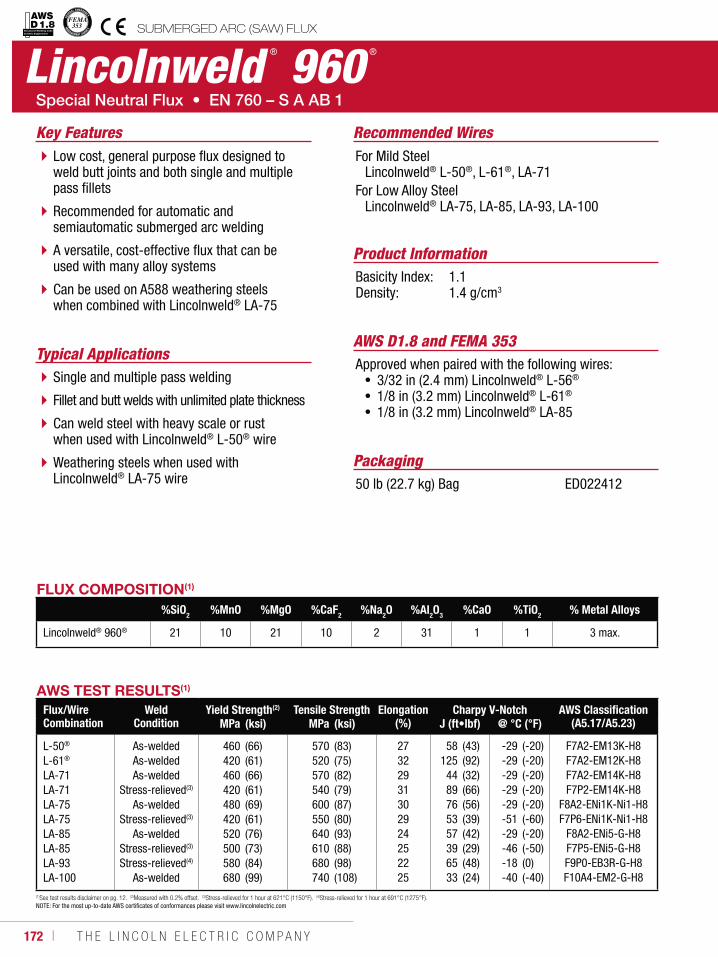
172 ı T H E L I N C O L N E L E C T R I C C O M P A N Y
Lincolnweld ® 960 ®
SUBMERGED ARC (SAW) FLUX
Recommended Wires
Typical Applications
For Mild Steel Lincolnweld® L-50®, L-61®, LA-71For Low Alloy Steel Lincolnweld® LA-75, LA-85, LA-93, LA-100
Single and multiple pass welding
Fillet and butt welds with unlimited plate thickness
Can weld steel with heavy scale or rust when used with Lincolnweld® L-50® wire
Weathering steels when used with Lincolnweld® LA-75 wire
Low cost, general purpose flux designed to weld butt joints and both single and multiple pass fillets
Recommended for automatic and semiautomatic submerged arc welding
A versatile, cost-effective flux that can be used with many alloy systems
Can be used on A588 weathering steels when combined with Lincolnweld® LA-75
Product InformationBasicity Index: 1.1Density: 1.4 g/cm3
Key Features
Packaging50 lb (22.7 kg) Bag ED022412
AWS D1.8 and FEMA 353Approved when paired with the following wires:
3/32 in (2.4 mm) Lincolnweld® L-56®
1/8 in (3.2 mm) Lincolnweld® L-61®
1/8 in (3.2 mm) Lincolnweld® LA-85
AWS TEST RESULTS(1)
Flux/Wire Combination
Weld Condition
Yield Strength(2) Tensile Strength Elongation (%)
Charpy V-Notch AWS Classification (A5.17/A5.23)MPa (ksi) MPa (ksi) J (ft•lbf) @ °C (°F)
L-50®
L-61®
LA-71LA-71LA-75LA-75LA-85LA-85LA-93LA-100
As-weldedAs-weldedAs-welded
Stress-relieved(3)
As-weldedStress-relieved(3)
As-weldedStress-relieved(3)
Stress-relieved(4)
As-welded
460420460420480420520500580680
(66)(61)(66)(61)(69)(61)(76)(73)(84)(99)
570520570540600550640610680740
(83)(75)(82)(79)(87)(80)(93)(88)(98)(108)
27322931302924252225
58125
4489765357396533
(43)(92)(32)(66)(56)(39)(42)(29)(48)(24)
-29-29-29-29-29-51-29-46-18-40
(-20)(-20)(-20)(-20)(-20)(-60)(-20)(-50)(0)(-40)
F7A2-EM13K-H8F7A2-EM12K-H8F7A2-EM14K-H8F7P2-EM14K-H8
F8A2-ENi1K-Ni1-H8F7P6-ENi1K-Ni1-H8
F8A2-ENi5-G-H8F7P5-ENi5-G-H8F9P0-EB3R-G-H8F10A4-EM2-G-H8
(1)See test results disclaimer on pg. 12. (2)Measured with 0.2% offset. (3)Stress-relieved for 1 hour at 621°C (1150°F). (4)Stress-relieved for 1 hour at 691°C (1275°F).NOTE: For the most up-to-date AWS certificates of conformances please visit www.lincolnelectric.com
FLUX COMPOSITION(1)
%SiO2 %MnO %MgO %CaF2 %Na2O %Al2O3 %CaO %TiO2 % Metal Alloys
Lincolnweld® 960® 21 10 21 10 2 31 1 1 3 max.
Structural Welding Code Seismic Supplement
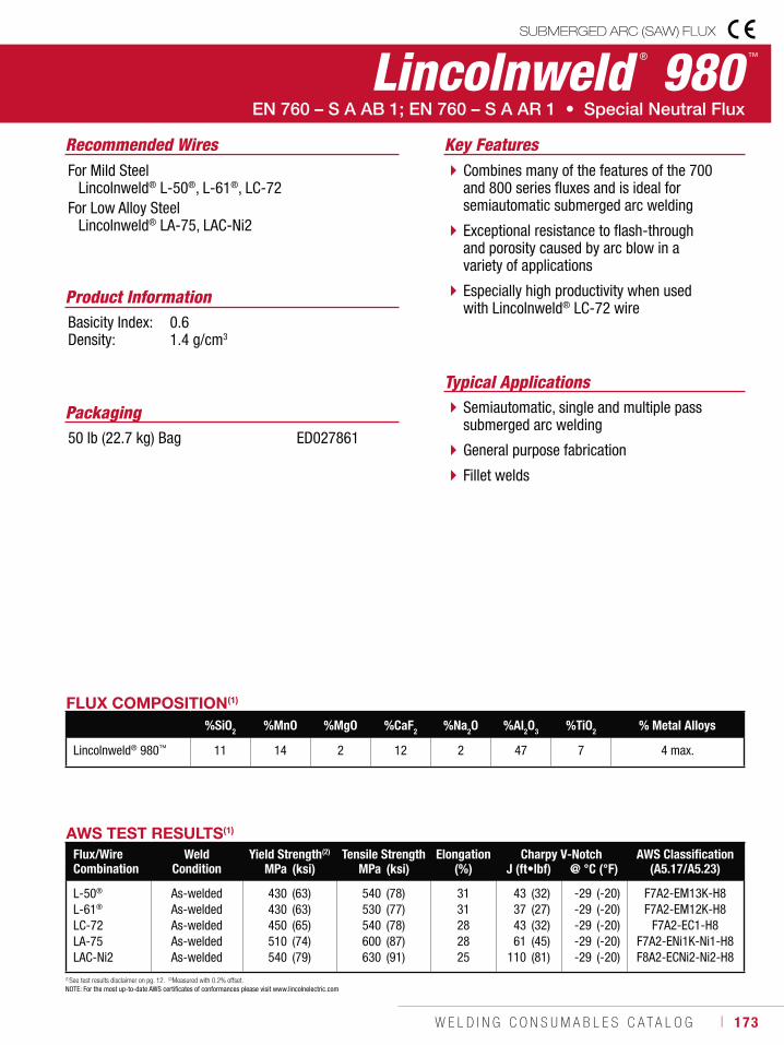
W E L D I N G C O N S U M A B L E S C A T A L O G ı 173
Lincolnweld ® 980 ™
SUBMERGED ARC (SAW) FLUX
Recommended Wires
Typical Applications
For Mild Steel Lincolnweld® L-50®, L-61®, LC-72For Low Alloy Steel Lincolnweld® LA-75, LAC-Ni2
Semiautomatic, single and multiple pass submerged arc welding
General purpose fabrication
Fillet welds
Combines many of the features of the 700 and 800 series fluxes and is ideal for semiautomatic submerged arc welding
Exceptional resistance to flash-through and porosity caused by arc blow in a variety of applications
Especially high productivity when used with Lincolnweld® LC-72 wire
Product InformationBasicity Index: 0.6Density: 1.4 g/cm3
Key Features
Packaging50 lb (22.7 kg) Bag ED027861
AWS TEST RESULTS(1)
Flux/Wire Combination
Weld Condition
Yield Strength(2) Tensile Strength Elongation (%)
Charpy V-Notch AWS Classification (A5.17/A5.23)MPa (ksi) MPa (ksi) J (ft•lbf) @ °C (°F)
L-50®
L-61®
LC-72LA-75LAC-Ni2
As-weldedAs-weldedAs-weldedAs-weldedAs-welded
430430450510540
(63)(63)(65)(74)(79)
540530540600630
(78)(77)(78)(87)(91)
3131282825
43374361
110
(32)(27)(32)(45)(81)
-29-29-29-29-29
(-20)(-20)(-20)(-20)(-20)
F7A2-EM13K-H8F7A2-EM12K-H8
F7A2-EC1-H8F7A2-ENi1K-Ni1-H8F8A2-ECNi2-Ni2-H8
(1)See test results disclaimer on pg. 12. (2)Measured with 0.2% offset. NOTE: For the most up-to-date AWS certificates of conformances please visit www.lincolnelectric.com
FLUX COMPOSITION(1)
%SiO2 %MnO %MgO %CaF2 %Na2O %Al2O3 %TiO2 % Metal Alloys
Lincolnweld® 980™ 11 14 2 12 2 47 7 4 max.
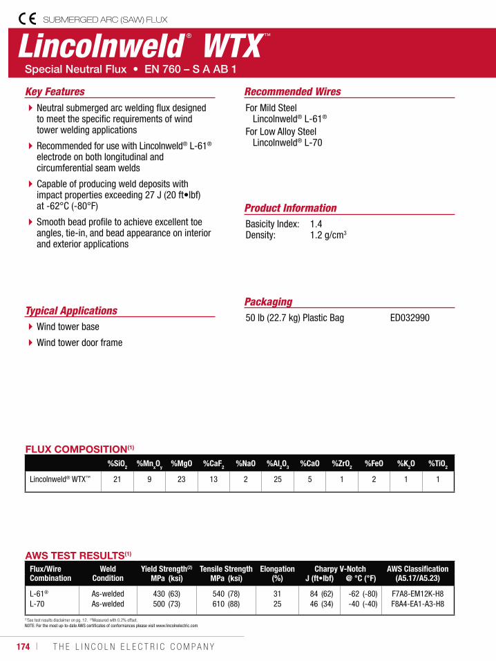
174 ı T H E L I N C O L N E L E C T R I C C O M P A N Y
SUBMERGED ARC (SAW) FLUX
Lincolnweld ® WTX ™
Recommended Wires
Typical Applications
For Mild Steel Lincolnweld® L-61®
For Low Alloy Steel Lincolnweld® L-70
Wind tower base
Wind tower door frame
Neutral submerged arc welding flux designed to meet the specific requirements of wind tower welding applications
Recommended for use with Lincolnweld® L-61® electrode on both longitudinal and circumferential seam welds
Capable of producing weld deposits with impact properties exceeding 27 J (20 ft•lbf) at -62°C (-80°F)
Smooth bead profile to achieve excellent toe angles, tie-in, and bead appearance on interior and exterior applications
Product InformationBasicity Index: 1.4Density: 1.2 g/cm3
Key Features
Packaging50 lb (22.7 kg) Plastic Bag ED032990
AWS TEST RESULTS(1)
Flux/Wire Combination
Weld Condition
Yield Strength(2) Tensile Strength Elongation (%)
Charpy V-Notch AWS Classification (A5.17/A5.23)MPa (ksi) MPa (ksi) J (ft•lbf) @ °C (°F)
L-61®
L-70As-weldedAs-welded
430500
(63)(73)
540610
(78)(88)
3125
8446
(62)(34)
-62-40
(-80)(-40)
F7A8-EM12K-H8F8A4-EA1-A3-H8
(1)See test results disclaimer on pg. 12. (2)Measured with 0.2% offset. NOTE: For the most up-to-date AWS certificates of conformances please visit www.lincolnelectric.com
FLUX COMPOSITION(1)
%SiO2 %MnxOy %MgO %CaF2 %NaO %Al2O3 %CaO %ZrO2 %FeO %K2O %TiO2
Lincolnweld® WTX™ 21 9 23 13 2 25 5 1 2 1 1
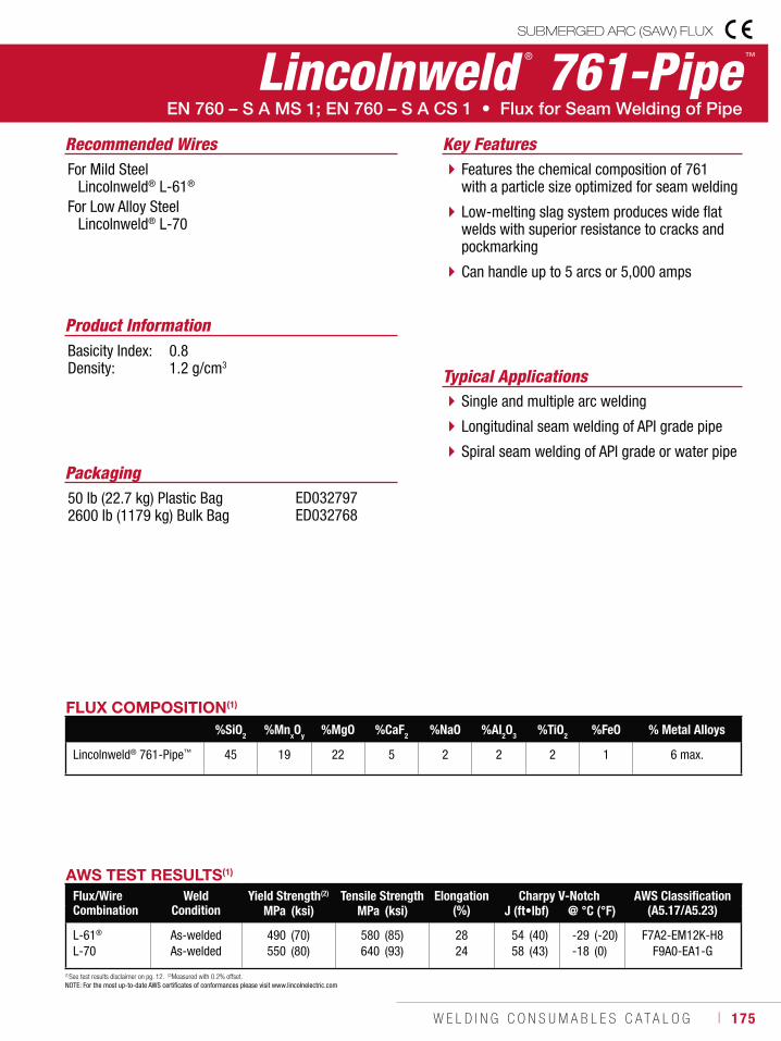
W E L D I N G C O N S U M A B L E S C A T A L O G ı 175
Lincolnweld ® 761-Pipe ™
SUBMERGED ARC (SAW) FLUX
Recommended Wires
Typical Applications
For Mild Steel Lincolnweld® L-61®
For Low Alloy Steel Lincolnweld® L-70
Single and multiple arc welding
Longitudinal seam welding of API grade pipe
Spiral seam welding of API grade or water pipe
Features the chemical composition of 761 with a particle size optimized for seam welding
Low-melting slag system produces wide flat welds with superior resistance to cracks and pockmarking
Can handle up to 5 arcs or 5,000 amps
Product InformationBasicity Index: 0.8Density: 1.2 g/cm3
Key Features
Packaging50 lb (22.7 kg) Plastic Bag2600 lb (1179 kg) Bulk Bag
ED032797ED032768
AWS TEST RESULTS(1)
Flux/Wire Combination
Weld Condition
Yield Strength(2) Tensile Strength Elongation (%)
Charpy V-Notch AWS Classification (A5.17/A5.23)MPa (ksi) MPa (ksi) J (ft•lbf) @ °C (°F)
L-61®
L-70As-weldedAs-welded
490550
(70)(80)
580640
(85)(93)
2824
5458
(40)(43)
-29-18
(-20)(0)
F7A2-EM12K-H8F9A0-EA1-G
(1)See test results disclaimer on pg. 12. (2)Measured with 0.2% offset. NOTE: For the most up-to-date AWS certificates of conformances please visit www.lincolnelectric.com
FLUX COMPOSITION(1)
%SiO2 %MnxOy %MgO %CaF2 %NaO %Al2O3 %TiO2 %FeO % Metal Alloys
Lincolnweld® 761-Pipe™ 45 19 22 5 2 2 2 1 6 max.
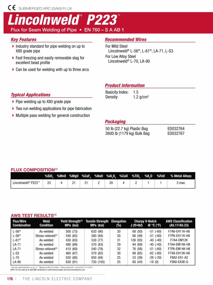
176 ı T H E L I N C O L N E L E C T R I C C O M P A N Y
SUBMERGED ARC (SAW) FLUX
Lincolnweld ® P223 ™
Recommended Wires
Typical Applications
For Mild Steel Lincolnweld® L-56®, L-61®, LA-71, L-S3For Low Alloy Steel Lincolnweld® L-70, LA-90
Pipe welding up to X80 grade pipe
Two run welding applications for pipe fabrication
Multiple pass welding for general construction
Industry standard for pipe welding on up to X80 grade pipe
Fast freezing and easily removable slag for excellent bead profile
Can be used for welding with up to three arcs
Product InformationBasicity Index: 1.5Density: 1.2 g/cm3
Key Features
Packaging50 lb (22.7 kg) Plastic Bag 2600 lb (1179 kg) Bulk Bag
ED032764 ED032767
AWS TEST RESULTS(1)
Flux/Wire Combination
Weld Condition
Yield Strength(2) Tensile Strength Elongation(%)
Charpy V-Notch AWS Classification (A5.17/A5.23)MPa (ksi) MPa (ksi) J (ft•lbf) @ °C (°F)
L-56®
L-56®
L-61®
LA-71LA-71L-S3L-70LA-90
As-weldedStress-relieved(3)
As-weldedAs-welded
Stress-relieved(3)
As-weldedAs-weldedAs-welded
500540430480410460550630
(73)(65)(63)(69)(60)(67)(80)(91)
620580530570540570650720
(90)(84)(77)(83)(78)(82)(94)(105)
3030312932302525
6866
1269476885360
(50)(49)(93)(69)(56)(65)(39)(44)
-51-51-40-40-51-62-29-18
(-60)(-60)(-40)(-40)(-60)(-80)(-20)(0)
F7A6-EH11K-H8F7P6-EH11K-H8
F7A4-EM12KF7A4-EM14K-H8F7P6-EM14K-H8F7A8-EH12K-H8
F8A2-EA1-A2F9A0-EA3K-G
(1)See test results disclaimer on pg. 12. (2)Measured with 0.2% offset. (3)Stress-relieved for 1 hour at 621°C (1150°F).NOTE: For the most up-to-date AWS certificates of conformances please visit www.lincolnelectric.com
FLUX COMPOSITION(1)
%SiO2 %MnO %MgO %CaF2 %NaO %Al2O3 %CaO %TiO2 %K2O %FeO % Metal Alloys
Lincolnweld® P223™ 23 4 21 21 2 20 4 2 1 1 3 max.
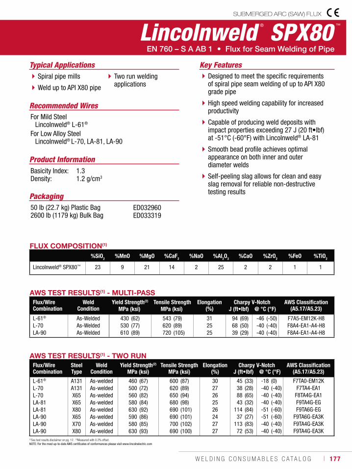
W E L D I N G C O N S U M A B L E S C A T A L O G ı 177
Lincolnweld ® SPX80 ™
SUBMERGED ARC (SAW) FLUX
Recommended Wires
Typical Applications
For Mild Steel Lincolnweld® L-61®
For Low Alloy Steel Lincolnweld® L-70, LA-81, LA-90
Spiral pipe mills
Weld up to API X80 pipe
Two run welding applications
Designed to meet the specific requirements of spiral pipe seam welding of up to API X80 grade pipe
High speed welding capability for increased productivity
Capable of producing weld deposits with impact properties exceeding 27 J (20 ft•lbf) at -51°C (-60°F) with Lincolnweld® LA-81
Smooth bead profile achieves optimal appearance on both inner and outer diameter welds
Self-peeling slag allows for clean and easy slag removal for reliable non-destructive testing results
Product InformationBasicity Index: 1.3Density: 1.2 g/cm3
Key Features
Packaging50 lb (22.7 kg) Plastic Bag2600 lb (1179 kg) Bulk Bag
ED032960ED033319
AWS TEST RESULTS(1) - MULTI-PASSFlux/Wire Combination
Weld Condition
Yield Strength(2) Tensile Strength Elongation (%)
Charpy V-Notch AWS Classification (A5.17/A5.23)MPa (ksi) MPa (ksi) J (ft•lbf) @ °C (°F)
L-61®
L-70LA-90
As-WeldedAs-WeldedAs-Welded
430530610
(62)(77)(89)
543620720
(79)(89)(105)
312525
946839
(69)(50)(29)
-46-40-40
(-50)(-40)(-40)
F7A5-EM12K-H8F8A4-EA1-A4-H8F8A4-EA1-A4-H8
FLUX COMPOSITION(1)
%SiO2 %MnO %MgO %CaF2 %NaO %Al2O3 %CaO %ZrO2 %FeO %TiO2
Lincolnweld® SPX80™ 23 9 21 14 2 25 2 2 1 1
AWS TEST RESULTS(1) - TWO RUNFlux/Wire Combination
SteelType
Weld Condition
Yield Strength(2) Tensile Strength Elongation (%)
Charpy V-Notch AWS Classification (A5.17/A5.23)MPa (ksi) MPa (ksi) J (ft•lbf) @ °C (°F)
L-61®
L-70L-70LA-81LA-81LA-90LA-90LA-90
A131A131X65X65X80X65X70X80
As-weldedAs-weldedAs-weldedAs-weldedAs-weldedAs-weldedAs-weldedAs-welded
460500560580630590580630
(67)(72)(82)(84)(92)(86)(85)(93)
600620650680690690700690
(87)(89)(94)(98)(101)(101)(102)(100)
3027262526242727
45388843
11437
11372
(33)(28)(65)(32)(84)(27)(83)(53)
-18-40-40-40-51-51-40-40
(0)(-40)(-40)(-40)(-60)(-60)(-40)(-40)
F7TA0-EM12KF7TA4-EA1
F8TA4G-EA1F9TA4G-EGF9TA6G-EG
F9TA6G-EA3KF9TA4G-EA3KF9TA4G-EA3K
(1)See test results disclaimer on pg. 12. (2)Measured with 0.2% offset. NOTE: For the most up-to-date AWS certificates of conformances please visit www.lincolnelectric.com
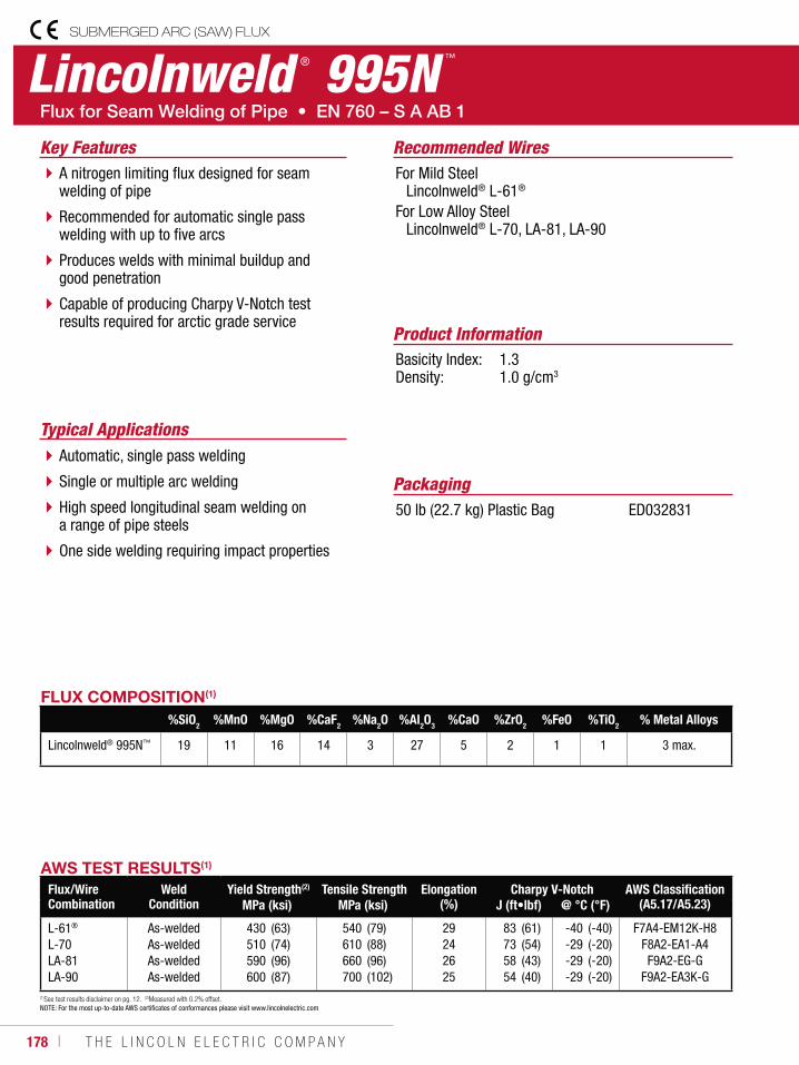
178 ı T H E L I N C O L N E L E C T R I C C O M P A N Y
Lincolnweld ® 995N ™
SUBMERGED ARC (SAW) FLUX
Recommended Wires
Typical Applications
For Mild Steel Lincolnweld® L-61®
For Low Alloy Steel Lincolnweld® L-70, LA-81, LA-90
Automatic, single pass welding
Single or multiple arc welding
High speed longitudinal seam welding on a range of pipe steels
One side welding requiring impact properties
A nitrogen limiting flux designed for seam welding of pipe
Recommended for automatic single pass welding with up to five arcs
Produces welds with minimal buildup and good penetration
Capable of producing Charpy V-Notch test results required for arctic grade service
Product InformationBasicity Index: 1.3Density: 1.0 g/cm3
Key Features
Packaging50 lb (22.7 kg) Plastic Bag ED032831
AWS TEST RESULTS(1)
Flux/Wire Combination
Weld Condition
Yield Strength(2) Tensile Strength Elongation (%)
Charpy V-Notch AWS Classification (A5.17/A5.23)MPa (ksi) MPa (ksi) J (ft•lbf) @ °C (°F)
L-61®
L-70LA-81LA-90
As-weldedAs-weldedAs-weldedAs-welded
430510590600
(63)(74)(96)(87)
540610660700
(79)(88)(96)(102)
29242625
83735854
(61)(54)(43)(40)
-40-29-29-29
(-40)(-20)(-20)(-20)
F7A4-EM12K-H8F8A2-EA1-A4F9A2-EG-G
F9A2-EA3K-G
FLUX COMPOSITION(1)
%SiO2 %MnO %MgO %CaF2 %Na2O %Al2O3 %CaO %ZrO2 %FeO %TiO2 % Metal Alloys
Lincolnweld® 995N™ 19 11 16 14 3 27 5 2 1 1 3 max.
(1)See test results disclaimer on pg. 12. (2)Measured with 0.2% offset. NOTE: For the most up-to-date AWS certificates of conformances please visit www.lincolnelectric.com
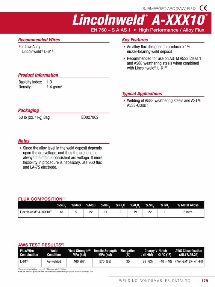
W E L D I N G C O N S U M A B L E S C A T A L O G ı 179
SUBMERGED ARC (SAW) FLUX
Lincolnweld ® A-XXX10 ™
Recommended Wires
Typical Applications
For Low Alloy Lincolnweld® L-61®
Welding of A588 weathering steels and ASTM A533-Class 1
An alloy flux designed to produce a 1% nickel-bearing weld deposit
Recommended for use on ASTM A533 Class 1 and A588 weathering steels when combined with Lincolnweld® L-61®
Product InformationBasicity Index: 1.0Density: 1.4 g/cm3
Key Features
Packaging50 lb (22.7 kg) Bag ED027862
AWS TEST RESULTS(1)
Flux/Wire Combination
Weld Condition
Yield Strength(2) Tensile Strength Elongation(%)
Charpy V-Notch AWS Classification (A5.17/A5.23)MPa (ksi) MPa (ksi) J (ft•lbf) @ °C (°F)
L-61® As-welded 460 (67) 570 (83) 30 85 (63) -40 (-40) F7A4-EM12K-Ni1-H8
FLUX COMPOSITION(1)
%SiO2 %MnO %MgO %CaF2 %Na2O %Al2O3 %ZrO2 %TiO2 % Metal Alloys
Lincolnweld® A-XXX10™ 18 5 22 11 2 19 22 1 5 max.
(1)See test results disclaimer on pg. 12. (2)Measured with 0.2% offset.
NOTE: For the most up-to-date AWS certificates of conformances please visit www.lincolnelectric.com
NotesSince the alloy level in the weld deposit depends upon the arc voltage, and thus the arc length, always maintain a consistent arc voltage. If more flexibility in procedure is necessary, use 960 flux and LA-75 electrode.
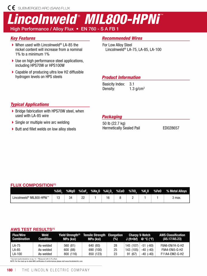
180 ı T H E L I N C O L N E L E C T R I C C O M P A N Y
Lincolnweld ® MIL800-HPNi ™
SUBMERGED ARC (SAW) FLUX
Recommended Wires
Typical Applications
For Low Alloy Steel Lincolnweld® LA-75, LA-85, LA-100
Bridge fabrication with HPS70W steel, when used with LA-85 wire
Single or multiple wire arc welding
Butt and fillet welds on low alloy steels
When used with Lincolnweld® LA-85 the nickel content will increase from a nominal 1% to a minimum 1%
Use on high performance steel applications, including HPS70W or HPS100W
Capable of producing ultra low H2 diffusible hydrogen levels on HPS steels Product Information
Basicity Index: 3.1Density: 1.3 g/cm3
Key Features
Packaging50 lb (22.7 kg) Hermetically Sealed Pail ED028657
AWS TEST RESULTS(1)
Flux/Wire Combination
Weld Condition
Yield Strength(2) Tensile Strength Elongation(%)
Charpy V-Notch AWS Classification (A5.17/A5.23)MPa (ksi) MPa (ksi) J (ft•lbf) @ °C (°F)
LA-75LA-85LA-100
As-weldedAs-weldedAs-welded
560600800
(81)(88)(116)
640690850
(93)(100)(123)
282523
145143
91
(107)(105)(67)
-51-40-40
(-60)(-40)(-40)
F8A6-ENi1K-G-H2F9A4-ENi5-G-H2F11A4-EM2-G-H2
FLUX COMPOSITION(1)
%SiO2 %MgO %CaF2 %Na2O %Al2O3 %CaO %TiO2 %K2O %FeO % Metal Alloys
Lincolnweld® MIL800-HPNi™ 13 34 22 1 16 8 2 1 1 3 max.
(1)See test results disclaimer on pg. 12. (2)Measured with 0.2% offset. NOTE: For the most up-to-date AWS certificates of conformances please visit www.lincolnelectric.com
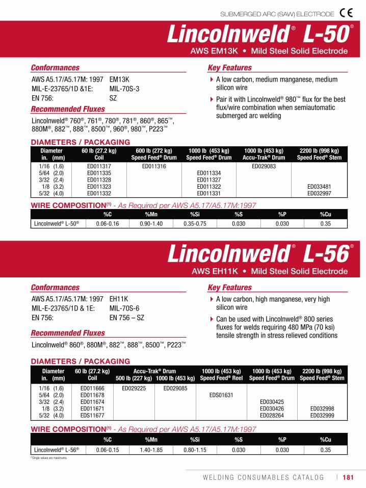
W E L D I N G C O N S U M A B L E S C A T A L O G ı 181
WIRE COMPOSITION(1)
%C %Mn %Si %S %P %Cu
Lincolnweld® L-50® 0.06-0.16 0.90-1.40 0.35-0.75 0.030 0.030 0.35
DIAMETERS / PACKAGINGDiameter 60 lb (27.2 kg)
Coil600 lb (272 kg)
Speed Feed® Drum1000 lb (453 kg)
Speed Feed® Drum1000 lb (453 kg)
Accu-Trak® Drum2200 lb (998 kg)
Speed Feed® Stemin. (mm)1/165/643/321/8
5/32
(1.6)(2.0)(2.4)(3.2)(4.0)
ED011317ED011335ED011328ED011323ED011332
ED011316ED011334ED011327ED011322ED011331
ED029083
ED033481ED032997
Lincolnweld ® L-50 ®
Recommended FluxesLincolnweld® 760®, 761®, 780®, 781®, 860®, 865™, 880M®, 882™, 888™, 8500™, 960®, 980™, P223™
A low carbon, medium manganese, medium silicon wire
Pair it with Lincolnweld® 980™ flux for the best flux/wire combination when semiautomatic submerged arc welding
Key FeaturesConformancesAWS A5.17/A5.17M: 1997MIL-E-23765/1D &1E:EN 756:
EM13KMIL-70S-3SZ
Recommended FluxesLincolnweld® 860®, 880M®, 882™, 888™, 8500™, P223™
A low carbon, high manganese, very high silicon wire
Can be used with Lincolnweld® 800 series fluxes for welds requiring 480 MPa (70 ksi) tensile strength in stress relieved conditions
Key FeaturesConformancesAWS A5.17/A5.17M: 1997MIL-E-23765/1D & 1E: EN 756:
EH11KMIL-70S-6EN 756 – SZ
WIRE COMPOSITION(1)
%C %Mn %Si %S %P %Cu
Lincolnweld® L-56® 0.06-0.15 1.40-1.85 0.80-1.15 0.030 0.030 0.35
DIAMETERS / PACKAGINGDiameter 60 lb (27.2 kg)
CoilAccu-Trak® Drum 1000 lb (453 kg)
Speed Feed® Reel1000 lb (453 kg)
Speed Feed® Drum2200 lb (998 kg)
Speed Feed® Stemin. (mm) 500 lb (227 kg) 1000 lb (453 kg)
1/165/643/321/8
5/32
(1.6)(2.0)(2.4)(3.2)(4.0)
ED011666ED011678ED011674ED011671EDS11677
ED029225 ED029085EDS01631
ED030425ED030426ED028264
ED032998ED032999
(1)Single values are maximums.
Lincolnweld ® L-56 ®
SUBMERGED ARC (SAW) ELECTRODE
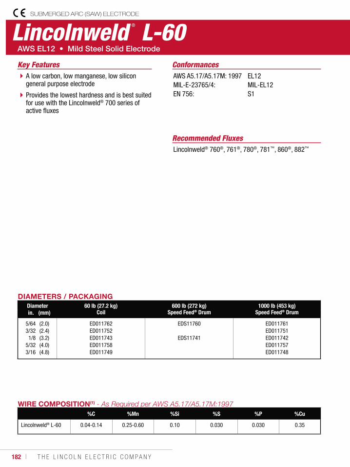
182 ı T H E L I N C O L N E L E C T R I C C O M P A N Y
Lincolnweld ® L-60
Recommended FluxesLincolnweld® 760®, 761®, 780®, 781™, 860®, 882™
A low carbon, low manganese, low silicon general purpose electrode
Provides the lowest hardness and is best suited for use with the Lincolnweld® 700 series of active fluxes
Key Features ConformancesAWS A5.17/A5.17M: 1997MIL-E-23765/4: EN 756:
EL12MIL-EL12S1
WIRE COMPOSITION(1)
%C %Mn %Si %S %P %Cu
Lincolnweld® L-60 0.04-0.14 0.25-0.60 0.10 0.030 0.030 0.35
DIAMETERS / PACKAGINGDiameter 60 lb (27.2 kg)
Coil600 lb (272 kg)
Speed Feed® Drum1000 lb (453 kg)
Speed Feed® Drumin. (mm)
5/643/321/8
5/323/16
(2.0)(2.4)(3.2)(4.0)(4.8)
ED011762ED011752ED011743ED011758ED011749
EDS11760
EDS11741
ED011761ED011751ED011742ED011757ED011748
SUBMERGED ARC (SAW) ELECTRODE
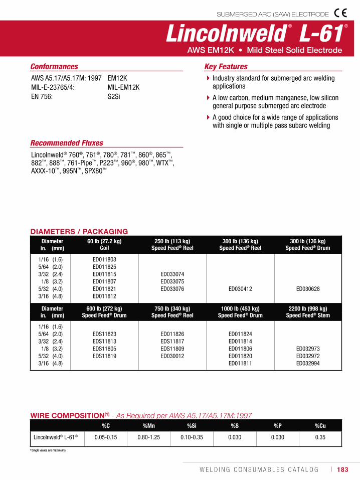
W E L D I N G C O N S U M A B L E S C A T A L O G ı 183
Recommended FluxesLincolnweld® 760®, 761®, 780®, 781™, 860®, 865™, 882™, 888™, 761-Pipe™, P223™, 960®, 980™, WTX™, AXXX-10™, 995N™, SPX80™
ConformancesAWS A5.17/A5.17M: 1997MIL-E-23765/4: EN 756:
EM12KMIL-EM12KS2Si
(1)Single values are maximums.
Industry standard for submerged arc welding applications
A low carbon, medium manganese, low silicon general purpose submerged arc electrode
A good choice for a wide range of applications with single or multiple pass subarc welding
Key Features
WIRE COMPOSITION(1)
%C %Mn %Si %S %P %Cu
Lincolnweld® L-61® 0.05-0.15 0.80-1.25 0.10-0.35 0.030 0.030 0.35
(1)Single values are maximums.
DIAMETERS / PACKAGINGDiameter 60 lb (27.2 kg)
Coil250 lb (113 kg)
Speed Feed® Reel300 lb (136 kg)
Speed Feed® Reel300 lb (136 kg)
Speed Feed® Drumin. (mm)
1/16 5/64 3/32 1/8 5/32 3/16
(1.6)(2.0)(2.4)(3.2)(4.0)(4.8)
ED011803ED011825ED011815ED011807ED011821ED011812
ED033074ED033075ED033076 ED030412 ED030628
Diameter 600 lb (272 kg)Speed Feed® Drum
750 lb (340 kg)Speed Feed® Reel
1000 lb (453 kg)Speed Feed® Drum
2200 lb (998 kg)Speed Feed® Stemin. (mm)
1/16 5/64 3/32 1/8 5/32 3/16
(1.6)(2.0)(2.4)(3.2)(4.0)(4.8)
EDS11823EDS11813EDS11805EDS11819
ED011826EDS11817EDS11809ED030012
ED011824ED011814ED011806ED011820ED011811
ED032973ED032972ED032994
Lincolnweld ® L-61 ®
SUBMERGED ARC (SAW) ELECTRODE
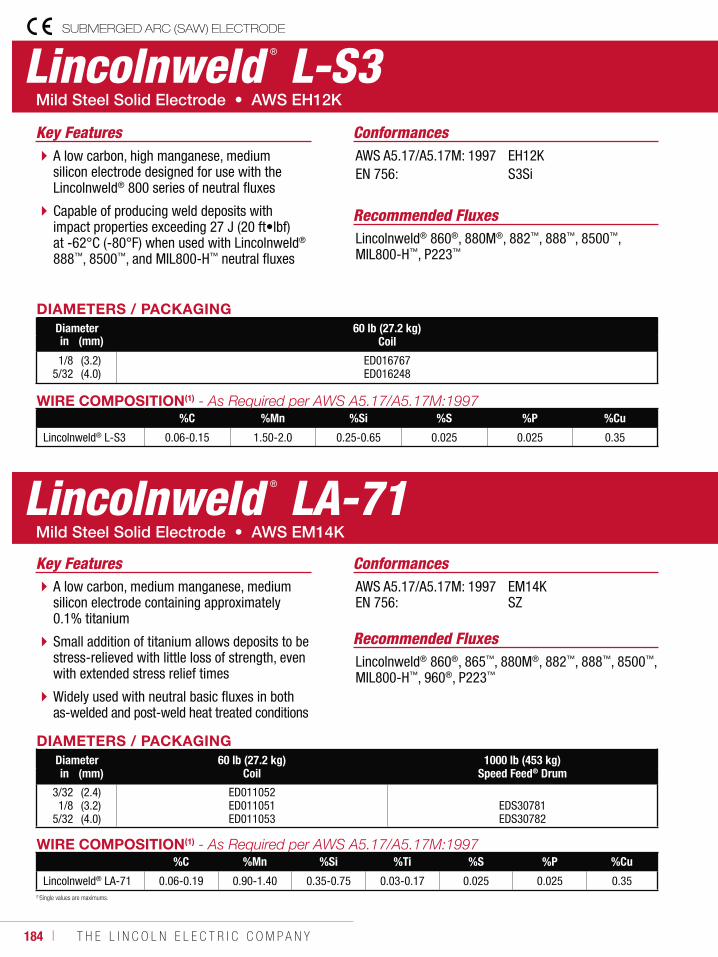
184 ı T H E L I N C O L N E L E C T R I C C O M P A N Y
SUBMERGED ARC (SAW) ELECTRODE
Lincolnweld ® L-S3
A low carbon, high manganese, medium silicon electrode designed for use with the Lincolnweld® 800 series of neutral fluxes
Capable of producing weld deposits with impact properties exceeding 27 J (20 ft•lbf) at -62°C (-80°F) when used with Lincolnweld® 888™, 8500™, and MIL800-H™ neutral fluxes
Key Features
Recommended FluxesLincolnweld® 860®, 880M®, 882™, 888™, 8500™, MIL800-H™, P223™
ConformancesAWS A5.17/A5.17M: 1997EN 756:
EH12KS3Si
WIRE COMPOSITION(1)
%C %Mn %Si %S %P %Cu
Lincolnweld® L-S3 0.06-0.15 1.50-2.0 0.25-0.65 0.025 0.025 0.35
(1)Single values are maximums.
DIAMETERS / PACKAGINGDiameter 60 lb (27.2 kg)
Coilin (mm)
1/85/32
(3.2)(4.0)
ED016767ED016248
Lincolnweld ® LA-71
A low carbon, medium manganese, medium silicon electrode containing approximately 0.1% titanium
Small addition of titanium allows deposits to be stress-relieved with little loss of strength, even with extended stress relief times
Widely used with neutral basic fluxes in both as-welded and post-weld heat treated conditions
Key Features
Recommended FluxesLincolnweld® 860®, 865™, 880M®, 882™, 888™, 8500™, MIL800-H™, 960®, P223™
ConformancesAWS A5.17/A5.17M: 1997EN 756:
EM14KSZ
WIRE COMPOSITION(1)
%C %Mn %Si %Ti %S %P %Cu
Lincolnweld® LA-71 0.06-0.19 0.90-1.40 0.35-0.75 0.03-0.17 0.025 0.025 0.35
DIAMETERS / PACKAGINGDiameter 60 lb (27.2 kg)
Coil1000 lb (453 kg)
Speed Feed® Drumin (mm)
3/321/8
5/32
(2.4)(3.2)(4.0)
ED011052ED011051ED011053
EDS30781EDS30782
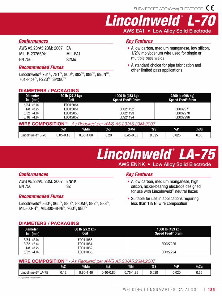
W E L D I N G C O N S U M A B L E S C A T A L O G ı 185
SUBMERGED ARC (SAW) ELECTRODE
(1)Single values are maximums.
Lincolnweld ® L-70
A low carbon, medium manganese, low silicon, 1/2% molybdenum wire used for single or multiple pass welds
A standard choice for pipe fabrication and other limited pass applications
Key Features
Recommended FluxesLincolnweld® 761®, 781™, 860®, 882™, 888™, 995N™, 761-Pipe™, P223™, SPX80™
ConformancesAWS A5.23/A5.23M: 2007MIL-E-23765/4: EN 756:
EA1MIL-EA1S2Mo
WIRE COMPOSITION(1)
%C %Mn %Si %Mo %S %P %Cu
Lincolnweld® L-70 0.05-0.15 0.65-1.00 0.20 0.45-0.65 0.025 0.025 0.35
DIAMETERS / PACKAGINGDiameter 60 lb (27.2 kg)
Coil1000 lb (453 kg)
Speed Feed® Drum2200 lb (998 kg)
Speed Feed® Stemin (mm)5/641/8
5/323/16
(2.0)(3.2)(4.0)(4.8)
ED012054ED012051ED012053ED012052
ED021192ED021193EDS21194
ED032971ED032970ED032996
Lincolnweld ® LA-75
A low carbon, medium manganese, high silicon, nickel-bearing electrode designed for use with Lincolnweld® neutral fluxes
Suitable for use in applications requiring less than 1% Ni wire composition
Key Features
Recommended FluxesLincolnweld® 860®, 865™, 880™, 880M®, 882™, 888™, MIL800-H™, MIL800-HPNi™, 960®, 980™
ConformancesAWS A5.23/A5.23M: 2007EN 756:
ENi1KSZ
WIRE COMPOSITION(1)
%C %Mn %Si %Ni %S %P %Cu
Lincolnweld® LA-75 0.12 0.80-1.40 0.40-0.80 0.75-1.25 0.020 0.020 0.35
DIAMETERS / PACKAGINGDiameter 60 lb (27.2 kg)
Coil1000 lb (453 kg)
Speed Feed® Drumin (mm)
5/643/321/8
5/32
(2.0)(2.4)(3.2)(4.0)
ED011066ED011064ED011062ED011065
ED027225
ED027224
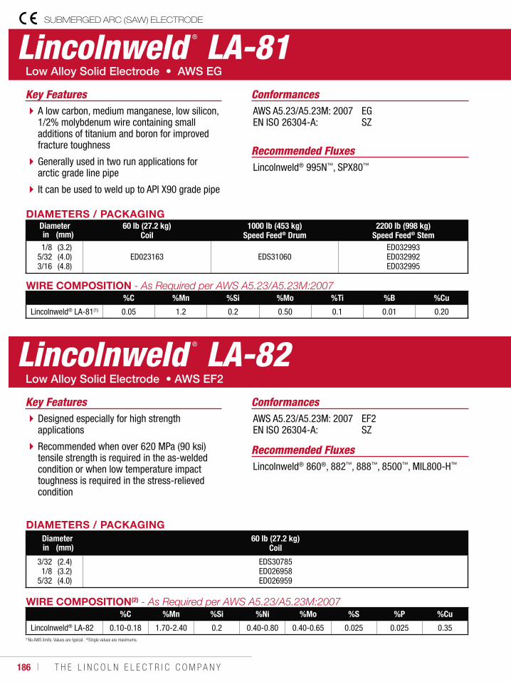
186 ı T H E L I N C O L N E L E C T R I C C O M P A N Y
(1)No AWS limits. Values are typical. (2)Single values are maximums.
Lincolnweld ® LA-81
A low carbon, medium manganese, low silicon, 1/2% molybdenum wire containing small additions of titanium and boron for improved fracture toughness
Generally used in two run applications for arctic grade line pipe
It can be used to weld up to API X90 grade pipe
Key Features
Recommended FluxesLincolnweld® 995N™, SPX80™
ConformancesAWS A5.23/A5.23M: 2007EN ISO 26304-A:
EGSZ
WIRE COMPOSITION%C %Mn %Si %Mo %Ti %B %Cu
Lincolnweld® LA-81(1) 0.05 1.2 0.2 0.50 0.1 0.01 0.20
DIAMETERS / PACKAGINGDiameter 60 lb (27.2 kg)
Coil1000 lb (453 kg)
Speed Feed® Drum2200 lb (998 kg)
Speed Feed® Stemin (mm)
1/85/323/16
(3.2)(4.0)(4.8)
ED023163 EDS31060ED032993ED032992ED032995
Lincolnweld ® LA-82
Designed especially for high strength applications
Recommended when over 620 MPa (90 ksi) tensile strength is required in the as-welded condition or when low temperature impact toughness is required in the stress-relieved condition
Key Features
Recommended FluxesLincolnweld® 860®, 882™, 888™, 8500™, MIL800-H™
ConformancesAWS A5.23/A5.23M: 2007EN ISO 26304-A:
EF2SZ
WIRE COMPOSITION(2)
%C %Mn %Si %Ni %Mo %S %P %Cu
Lincolnweld® LA-82 0.10-0.18 1.70-2.40 0.2 0.40-0.80 0.40-0.65 0.025 0.025 0.35
DIAMETERS / PACKAGINGDiameter 60 lb (27.2 kg)
Coilin (mm)
3/321/8
5/32
(2.4)(3.2)(4.0)
EDS30785ED026958ED026959
SUBMERGED ARC (SAW) ELECTRODE
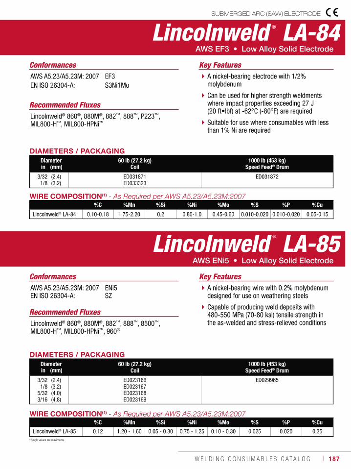
W E L D I N G C O N S U M A B L E S C A T A L O G ı 187
Lincolnweld ® LA-84
A nickel-bearing electrode with 1/2% molybdenum
Can be used for higher strength weldments where impact properties exceeding 27 J (20 ft•lbf) at -62°C (-80°F) are required
Suitable for use where consumables with less than 1% Ni are required
Key Features
Recommended FluxesLincolnweld® 860®, 880M®, 882™, 888™, P223™, MIL800-H™, MIL800-HPNi™
ConformancesAWS A5.23/A5.23M: 2007EN ISO 26304-A:
EF3S3Ni1Mo
WIRE COMPOSITION(1)
%C %Mn %Si %Ni %Mo %S %P %Cu
Lincolnweld® LA-84 0.10-0.18 1.75-2.20 0.2 0.80-1.0 0.45-0.60 0.010-0.020 0.010-0.020 0.05-0.15
DIAMETERS / PACKAGINGDiameter 60 lb (27.2 kg)
Coil1000 lb (453 kg)
Speed Feed® Drumin (mm)
3/321/8
(2.4)(3.2)
ED031871ED033323
ED031872
(1)Single values are maximums.
Lincolnweld ® LA-85
A nickel-bearing wire with 0.2% molybdenum designed for use on weathering steels
Capable of producing weld deposits with 480-550 MPa (70-80 ksi) tensile strength in the as-welded and stress-relieved conditions
Key Features
Recommended FluxesLincolnweld® 860®, 880M®, 882™, 888™, 8500™, MIL800-H™, MIL800-HPNi™, 960®
ConformancesAWS A5.23/A5.23M: 2007EN ISO 26304-A:
ENi5SZ
WIRE COMPOSITION(1)
%C %Mn %Si %Ni %Mo %S %P %Cu
Lincolnweld® LA-85 0.12 1.20 - 1.60 0.05 - 0.30 0.75 - 1.25 0.10 - 0.30 0.025 0.020 0.35
DIAMETERS / PACKAGINGDiameter 60 lb (27.2 kg)
Coil1000 lb (453 kg)
Speed Feed® Drumin (mm)
3/321/8
5/323/16
(2.4)(3.2)(4.0)(4.8)
ED023166ED023167ED023168ED023169
ED029965
SUBMERGED ARC (SAW) ELECTRODE
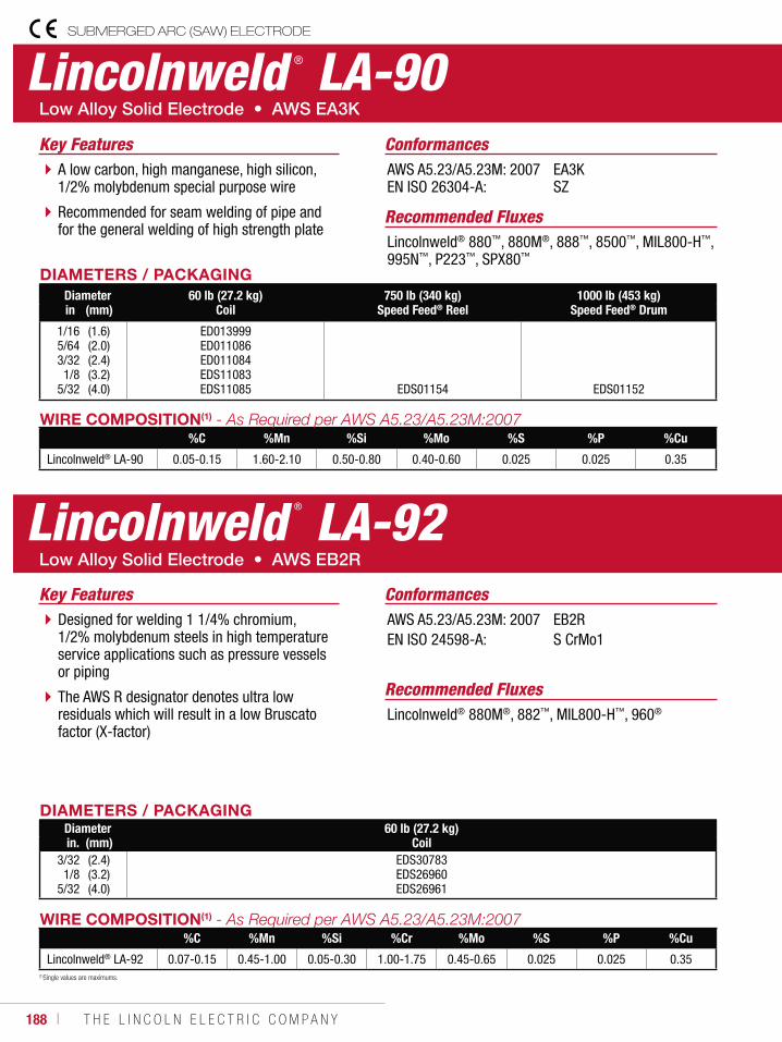
188 ı T H E L I N C O L N E L E C T R I C C O M P A N Y
(1)Single values are maximums.
Lincolnweld ® LA-90
A low carbon, high manganese, high silicon, 1/2% molybdenum special purpose wire
Recommended for seam welding of pipe and for the general welding of high strength plate
Key Features
Recommended FluxesLincolnweld® 880™, 880M®, 888™, 8500™, MIL800-H™, 995N™, P223™, SPX80™
ConformancesAWS A5.23/A5.23M: 2007EN ISO 26304-A:
EA3KSZ
WIRE COMPOSITION(1)
%C %Mn %Si %Mo %S %P %Cu
Lincolnweld® LA-90 0.05-0.15 1.60-2.10 0.50-0.80 0.40-0.60 0.025 0.025 0.35
DIAMETERS / PACKAGINGDiameter 60 lb (27.2 kg)
Coil750 lb (340 kg)
Speed Feed® Reel1000 lb (453 kg)
Speed Feed® Drumin (mm)
1/165/643/321/8
5/32
(1.6)(2.0)(2.4)(3.2)(4.0)
ED013999ED011086ED011084EDS11083EDS11085 EDS01154 EDS01152
SUBMERGED ARC (SAW) ELECTRODE
Lincolnweld ® LA-92
Designed for welding 1 1/4% chromium, 1/2% molybdenum steels in high temperature service applications such as pressure vessels or piping
The AWS R designator denotes ultra low residuals which will result in a low Bruscato factor (X-factor)
Key Features
Recommended FluxesLincolnweld® 880M®, 882™, MIL800-H™, 960®
ConformancesAWS A5.23/A5.23M: 2007 EN ISO 24598-A:
EB2RS CrMo1
DIAMETERS / PACKAGINGDiameter 60 lb (27.2 kg)
Coilin. (mm)3/321/8
5/32
(2.4)(3.2)(4.0)
EDS30783EDS26960EDS26961
WIRE COMPOSITION(1)
%C %Mn %Si %Cr %Mo %S %P %Cu
Lincolnweld® LA-92 0.07-0.15 0.45-1.00 0.05-0.30 1.00-1.75 0.45-0.65 0.025 0.025 0.35
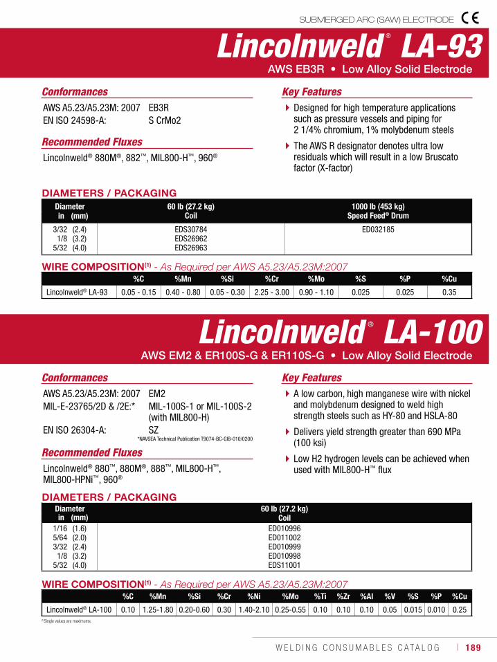
W E L D I N G C O N S U M A B L E S C A T A L O G ı 189
(1)Single values are maximums.
SUBMERGED ARC (SAW) ELECTRODE
Lincolnweld ® LA-93
Designed for high temperature applications such as pressure vessels and piping for 2 1/4% chromium, 1% molybdenum steels
The AWS R designator denotes ultra low residuals which will result in a low Bruscato factor (X-factor)
Key Features
Recommended FluxesLincolnweld® 880M®, 882™, MIL800-H™, 960®
ConformancesAWS A5.23/A5.23M: 2007EN ISO 24598-A:
EB3RS CrMo2
DIAMETERS / PACKAGINGDiameter 60 lb (27.2 kg)
Coil1000 lb (453 kg)
Speed Feed® Drumin (mm)
3/321/8
5/32
(2.4)(3.2)(4.0)
EDS30784EDS26962EDS26963
ED032185
WIRE COMPOSITION(1)
%C %Mn %Si %Cr %Mo %S %P %Cu
Lincolnweld® LA-93 0.05 - 0.15 0.40 - 0.80 0.05 - 0.30 2.25 - 3.00 0.90 - 1.10 0.025 0.025 0.35
Lincolnweld ® LA-100
A low carbon, high manganese wire with nickel and molybdenum designed to weld high strength steels such as HY-80 and HSLA-80
Delivers yield strength greater than 690 MPa (100 ksi)
Low H2 hydrogen levels can be achieved when used with MIL800-H™ flux
Key Features
Recommended FluxesLincolnweld® 880™, 880M®, 888™, MIL800-H™, MIL800-HPNi™, 960®
ConformancesAWS A5.23/A5.23M: 2007MIL-E-23765/2D & /2E:*
EN ISO 26304-A:
EM2MIL-100S-1 or MIL-100S-2 (with MIL800-H)SZ
DIAMETERS / PACKAGINGDiameter 60 lb (27.2 kg)
Coilin (mm)1/165/643/321/8
5/32
(1.6)(2.0)(2.4)(3.2)(4.0)
ED010996ED011002ED010999ED010998EDS11001
WIRE COMPOSITION(1)
%C %Mn %Si %Cr %Ni %Mo %Ti %Zr %Al %V %S %P %Cu
Lincolnweld® LA-100 0.10 1.25-1.80 0.20-0.60 0.30 1.40-2.10 0.25-0.55 0.10 0.10 0.10 0.05 0.015 0.010 0.25
*NAVSEA Technical Publication T9074-BC-GIB-010/0200
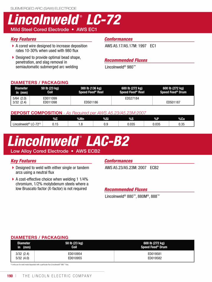
190 ı T H E L I N C O L N E L E C T R I C C O M P A N Y
Lincolnweld ® LC-72
A cored wire designed to increase deposition rates 10-30% when used with 980 flux
Designed to provide optimal bead shape, penetration, and slag removal in semiautomatic submerged arc welding
Key Features
Recommended FluxesLincolnweld® 980™
ConformancesAWS A5.17/A5.17M: 1997 EC1
DIAMETERS / PACKAGINGDiameter 50 lb (23 kg)
Coil300 lb (136 kg)
Speed Feed® Reel600 lb (272 kg)
Speed Feed® Reel600 lb (272 kg)
Speed Feed® Drumin (mm)
5/643/32
(2.0)(2.4)
ED011099ED011098 EDS01186
EDS27184EDS01187
DEPOSIT COMPOSITION%C %Mn %Si %S %P %Cu
Lincolnweld® LC-72(1) 0.15 1.8 0.9 0.035 0.035 0.35
(1)Limits are for weld metal deposited with a particular flux (Lincolnweld® 980™ flux).
SUBMERGED ARC (SAW) ELECTRODE
Lincolnweld ® LAC-B2
Designed to weld with either single or tandem arcs using a neutral flux
A cost-effective choice when welding 1 1/4% chromium, 1/2% molybdenum steels where a low Bruscato factor (X-factor) is not required
Key Features
Recommended FluxesLincolnweld® 880™, 880M®, 888™
ConformancesAWS A5.23/A5.23M: 2007 ECB2
DIAMETERS / PACKAGINGDiameter 50 lb (23 kg)
Coil600 lb (272 kg)
Speed Feed® Drumin (mm)
3/325/32
(2.4)(4.0)
ED010954ED010955
ED019581ED019582
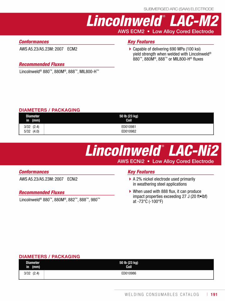
W E L D I N G C O N S U M A B L E S C A T A L O G ı 191
SUBMERGED ARC (SAW) ELECTRODE
Capable of delivering 690 MPa (100 ksi) yield strength when welded with Lincolnweld® 880™, 880M®, 888™ or MIL800-H® fluxes
Key Features
Recommended FluxesLincolnweld® 880™, 880M®, 888™, MIL800-H™
ConformancesAWS A5.23/A5.23M: 2007 ECM2
DIAMETERS / PACKAGINGDiameter 50 lb (23 kg)
Coilin (mm)
3/325/32
(2.4)(4.0)
ED010981ED010982
Lincolnweld ® LAC-M2
A 2% nickel electrode used primarily in weathering steel applications
When used with 888 flux, it can produce impact properties exceeding 27 J (20 ft•lbf) at -73°C (-100°F)
Key Features
Recommended FluxesLincolnweld® 880™, 880M®, 882™, 888™, 980™
ConformancesAWS A5.23/A5.23M: 2007 ECNi2
DIAMETERS / PACKAGINGDiameter 50 lb (23 kg)
Coilin (mm)
3/32 (2.4) ED010986
Lincolnweld ® LAC-Ni2
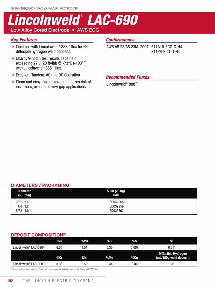
192 ı T H E L I N C O L N E L E C T R I C C O M P A N Y
Lincolnweld ® LAC-690SUBMERGED ARC (SAW) ELECTRODE
Combine with Lincolnweld® 888™ flux for H4 diffusible hydrogen weld deposits.
Charpy V-notch test results capable of exceeding 27 J (20 ft•lbf) @ -73°C (-100°F) with Lincolnweld® 888™ flux.
Excellent Tandem, AC and DC Operation
Clean and easy slag removal minimizes risk of inclusions, even in narrow gap applications.
Key Features
Recommended FluxesLincolnweld® 888™
ConformancesAWS A5.23/A5.23M: 2007
F11A10-ECG-G-H4 F11P6-ECG-G-H4
DIAMETERS / PACKAGINGDiameter 50 lb (23 kg)
Coilin (mm)
3/321/8
5/32
(2.4)(3.2)(4.0)
ED032958ED032959ED033302
DEPOSIT COMPOSITION(1)
%C %Mn %Si %S %P
Lincolnweld® LAC-690(2) 0.08 1.51 0.36 0.007 0.011
%Cr %Ni %Mo %CuDiffusible Hydrogen
(mL/100g weld deposit)
Lincolnweld® LAC-690(2) 0.36 2.59 0.44 0.04 3.6(1)See test results disclaimer on pg. 12. (2)Limits are for weld metal deposited with a particular flux (Lincolnweld® 888™ flux).
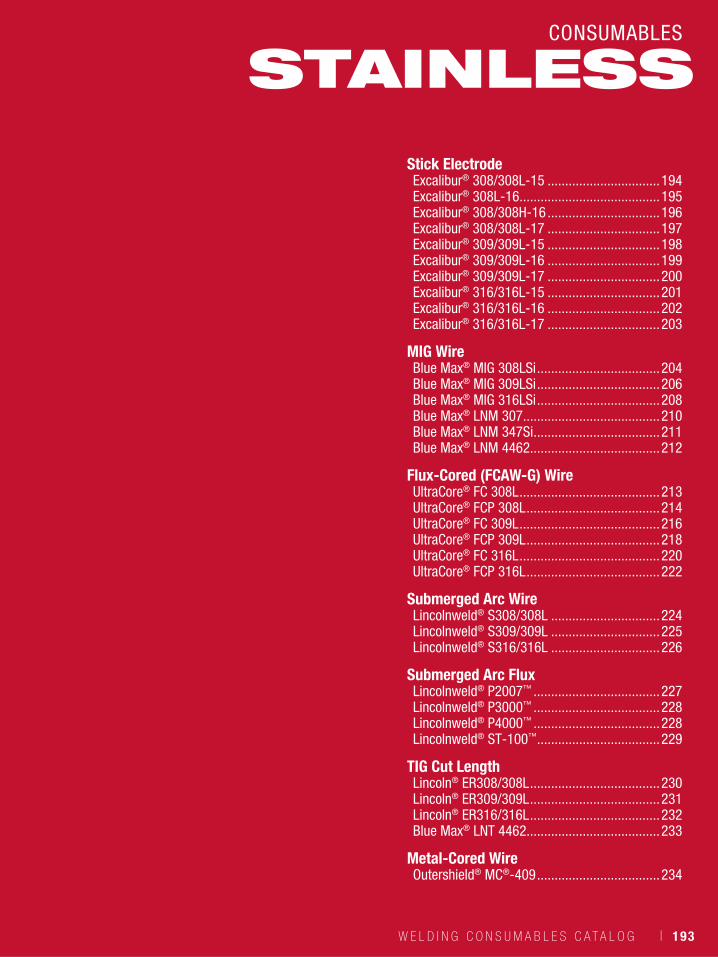
W E L D I N G C O N S U M A B L E S C A T A L O G ı 193
CONSUMABLES
Stick ElectrodeExcalibur® 308/308L-15 ................................194Excalibur® 308L-16........................................195Excalibur® 308/308H-16 ................................196Excalibur® 308/308L-17 ................................197Excalibur® 309/309L-15 ................................198Excalibur® 309/309L-16 ................................199Excalibur® 309/309L-17 ................................200Excalibur® 316/316L-15 ................................201Excalibur® 316/316L-16 ................................202Excalibur® 316/316L-17 ................................203
MIG WireBlue Max® MIG 308LSi ...................................204Blue Max® MIG 309LSi ...................................206Blue Max® MIG 316LSi ...................................208Blue Max® LNM 307.......................................210Blue Max® LNM 347Si ....................................211Blue Max® LNM 4462.....................................212
Flux-Cored (FCAW-G) WireUltraCore® FC 308L ........................................213UltraCore® FCP 308L ......................................214UltraCore® FC 309L ........................................216UltraCore® FCP 309L ......................................218UltraCore® FC 316L ........................................220UltraCore® FCP 316L ......................................222
Submerged Arc WireLincolnweld® S308/308L ...............................224Lincolnweld® S309/309L ...............................225Lincolnweld® S316/316L ...............................226
Submerged Arc FluxLincolnweld® P2007™ ....................................227Lincolnweld® P3000™ ....................................228Lincolnweld® P4000™ ....................................228Lincolnweld® ST-100™ ...................................229
TIG Cut LengthLincoln® ER308/308L .....................................230Lincoln® ER309/309L .....................................231Lincoln® ER316/316L .....................................232Blue Max® LNT 4462......................................233
Metal-Cored WireOutershield® MC®-409 ...................................234
STAINLESS
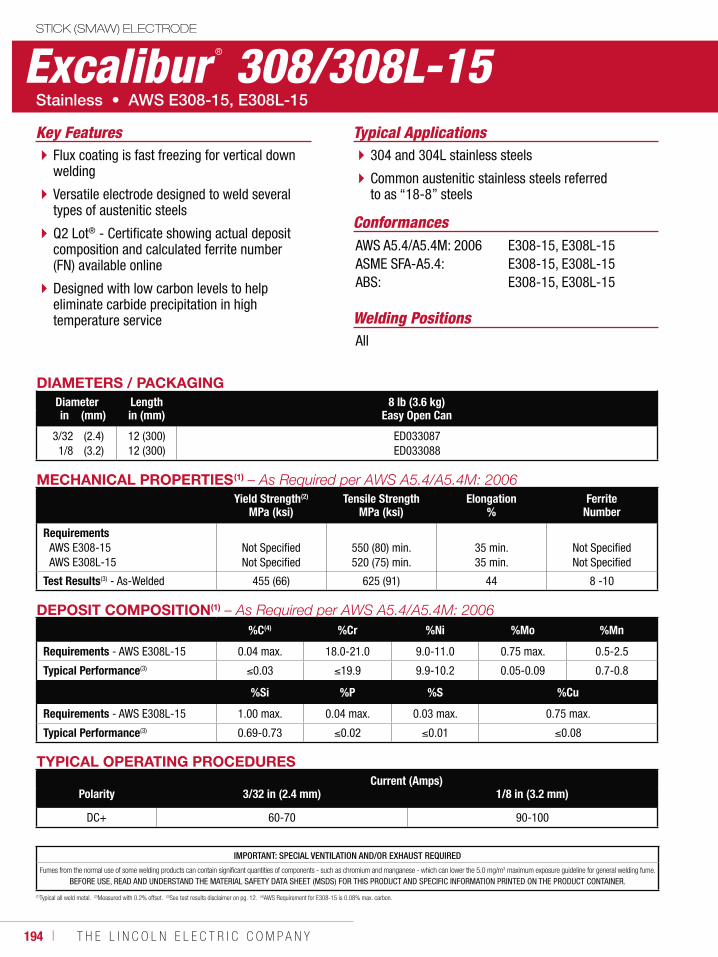
194 ı T H E L I N C O L N E L E C T R I C C O M P A N Y
Excalibur ® 308/308L-15STICK (SMAW) ELECTRODE
Welding Positions
Typical Applications
All
304 and 304L stainless steels
Common austenitic stainless steels referred to as “18-8” steels
Flux coating is fast freezing for vertical down welding
Versatile electrode designed to weld several types of austenitic steels
Q2 Lot® - Certificate showing actual deposit composition and calculated ferrite number (FN) available online
Designed with low carbon levels to help eliminate carbide precipitation in high temperature service
Conformances
Key Features
AWS A5.4/A5.4M: 2006ASME SFA-A5.4:ABS:
E308-15, E308L-15E308-15, E308L-15E308-15, E308L-15
DIAMETERS / PACKAGINGDiameter Length 8 lb (3.6 kg)
Easy Open Canin (mm) in (mm)
3/321/8
(2.4)(3.2)
12 (300)12 (300)
ED033087ED033088
MECHANICAL PROPERTIES(1)
Yield Strength(2)
MPa (ksi)Tensile Strength
MPa (ksi)Elongation
%Ferrite
Number
RequirementsAWS E308-15AWS E308L-15
Not SpecifiedNot Specified
550 (80) min.520 (75) min.
35 min.35 min.
Not SpecifiedNot Specified
Test Results(3) - As-Welded 455 (66) 625 (91) 44 8 -10
DEPOSIT COMPOSITION(1)
%C(4) %Cr %Ni %Mo %Mn
Requirements - AWS E308L-15 0.04 max. 18.0-21.0 9.0-11.0 0.75 max. 0.5-2.5
Typical Performance(3) 0.03 19.9 9.9-10.2 0.05-0.09 0.7-0.8
%Si %P %S %Cu
Requirements - AWS E308L-15 1.00 max. 0.04 max. 0.03 max. 0.75 max.
Typical Performance(3) 0.69-0.73 0.02 0.01 0.08
TYPICAL OPERATING PROCEDURESCurrent (Amps)
Polarity 3/32 in (2.4 mm) 1/8 in (3.2 mm)
DC+ 60-70 90-100
(1)Typical all weld metal. (2)Measured with 0.2% offset. (3)See test results disclaimer on pg. 12. (4)AWS Requirement for E308-15 is 0.08% max. carbon.
IMPORTANT: SPECIAL VENTILATION AND/OR EXHAUST REQUIRED
Fumes from the normal use of some welding products can contain significant quantities of components - such as chromium and manganese - which can lower the 5.0 mg/m3 maximum exposure guideline for general welding fume.
BEFORE USE, READ AND UNDERSTAND THE MATERIAL SAFETY DATA SHEET (MSDS) FOR THIS PRODUCT AND SPECIFIC INFORMATION PRINTED ON THE PRODUCT CONTAINER.
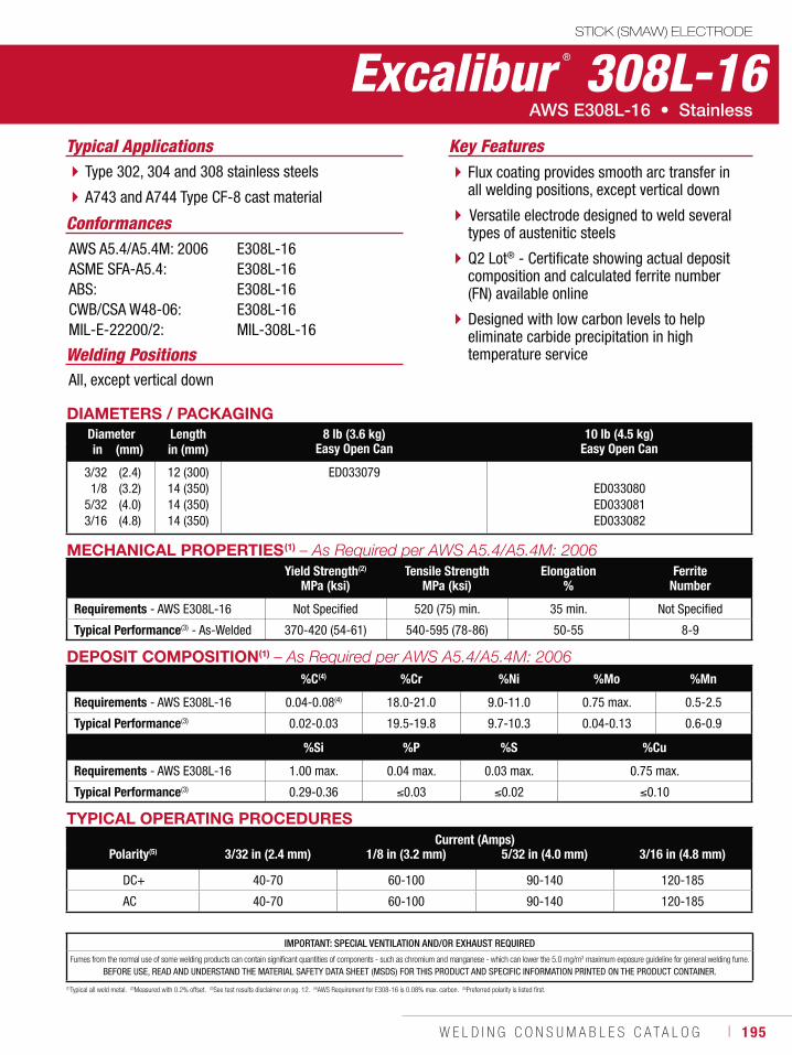
W E L D I N G C O N S U M A B L E S C A T A L O G ı 195
Excalibur ® 308L-16STICK (SMAW) ELECTRODE
Welding Positions
Typical Applications
All, except vertical down
Type 302, 304 and 308 stainless steels
A743 and A744 Type CF-8 cast material
Flux coating provides smooth arc transfer in all welding positions, except vertical down
Versatile electrode designed to weld several types of austenitic steels
Q2 Lot® - Certificate showing actual deposit composition and calculated ferrite number (FN) available online
Designed with low carbon levels to help eliminate carbide precipitation in high temperature service
Conformances
Key Features
AWS A5.4/A5.4M: 2006ASME SFA-A5.4:ABS:CWB/CSA W48-06:MIL-E-22200/2:
E308L-16E308L-16E308L-16E308L-16MIL-308L-16
DIAMETERS / PACKAGINGDiameter Length 8 lb (3.6 kg)
Easy Open Can10 lb (4.5 kg)
Easy Open Canin (mm) in (mm)
3/321/8
5/323/16
(2.4)(3.2)(4.0)(4.8)
12 (300) 14 (350)14 (350)14 (350)
ED033079ED033080ED033081ED033082
MECHANICAL PROPERTIES(1)
Yield Strength(2)
MPa (ksi)Tensile Strength
MPa (ksi)Elongation
%Ferrite
Number
Requirements - AWS E308L-16 Not Specified 520 (75) min. 35 min. Not Specified
Typical Performance(3) - As-Welded 370-420 (54-61) 540-595 (78-86) 50-55 8-9
TYPICAL OPERATING PROCEDURESCurrent (Amps)
Polarity(5) 3/32 in (2.4 mm) 1/8 in (3.2 mm) 5/32 in (4.0 mm) 3/16 in (4.8 mm)
DC+ 40-70 60-100 90-140 120-185
AC 40-70 60-100 90-140 120-185
(1)Typical all weld metal. (2)Measured with 0.2% offset. (3)See test results disclaimer on pg. 12. (4)AWS Requirement for E308-16 is 0.08% max. carbon. (5)Preferred polarity is listed first.
DEPOSIT COMPOSITION(1)
%C(4) %Cr %Ni %Mo %Mn
Requirements - AWS E308L-16 0.04-0.08(4) 18.0-21.0 9.0-11.0 0.75 max. 0.5-2.5
Typical Performance(3) 0.02-0.03 19.5-19.8 9.7-10.3 0.04-0.13 0.6-0.9
%Si %P %S %Cu
Requirements - AWS E308L-16 1.00 max. 0.04 max. 0.03 max. 0.75 max.
Typical Performance(3) 0.29-0.36 0.03 0.02 0.10
IMPORTANT: SPECIAL VENTILATION AND/OR EXHAUST REQUIRED
Fumes from the normal use of some welding products can contain significant quantities of components - such as chromium and manganese - which can lower the 5.0 mg/m3 maximum exposure guideline for general welding fume.
BEFORE USE, READ AND UNDERSTAND THE MATERIAL SAFETY DATA SHEET (MSDS) FOR THIS PRODUCT AND SPECIFIC INFORMATION PRINTED ON THE PRODUCT CONTAINER.
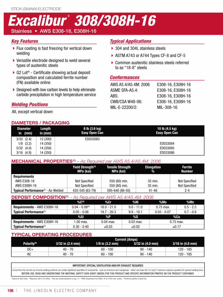
196 ı T H E L I N C O L N E L E C T R I C C O M P A N Y
DIAMETERS / PACKAGINGDiameter Length 8 lb (3.6 kg)
Easy Open Can10 lb (4.5 kg)
Easy Open Canin (mm) in (mm)
3/321/8
5/323/16
(2.4)(3.2)(4.0)(4.8)
12 (300)14 (350)14 (350)14 (350)
ED033083ED033084ED033085ED033086
MECHANICAL PROPERTIES(1)
Yield Strength(2)
MPa (ksi)Tensile Strength
MPa (ksi)Elongation
%Ferrite
NumberRequirements
AWS E308-16AWS E308H-16
Not SpecifiedNot Specified
550 (80) min.550 (80) min.
35 min.35 min.
Not SpecifiedNot Specified
Typical Performance(3) - As-Welded 435-545 (63-79) 595-640 (86-93) 41-48 2-4
TYPICAL OPERATING PROCEDURESCurrent (Amps)
Polarity(5) 3/32 in (2.4 mm) 1/8 in (3.2 mm) 5/32 in (4.0 mm) 3/16 in (4.8 mm)
DC+ 40 - 70 60 - 100 90 - 140 120 - 185AC 40 - 70 60 - 100 90 - 140 120 - 185
(1Typical all weld metal. (2)Measured with 0.2% offset. (3)See test results disclaimer on pg. 12. (4)AWS Requirement for E308L-16 is 0.04% max. carbon. (5)Preferred polarity is listed first.
DEPOSIT COMPOSITION(1)
%C(4) %Cr %Ni %Mo %MnRequirements - AWS E308H-16 0.04 - 0.08(4) 18.0 - 21.0 9.0 - 11.0 0.75 max. 0.5 - 2.5Typical Performance(3) 0.05 - 0.06 19.7 - 20.3 9.9 - 10.1 0.03 - 0.07 0.7 - 0.8
%Si %P %S %CuRequirements - AWS E308H-16 1.00 max. 0.04 max. 0.03 max. 0.75 max.Typical Performance(3) 0.30 - 0.40 0.03 0.02 0.17
IMPORTANT: SPECIAL VENTILATION AND/OR EXHAUST REQUIRED
Fumes from the normal use of some welding products can contain significant quantities of components - such as chromium and manganese - which can lower the 5.0 mg/m3 maximum exposure guideline for general welding fume.
BEFORE USE, READ AND UNDERSTAND THE MATERIAL SAFETY DATA SHEET (MSDS) FOR THIS PRODUCT AND SPECIFIC INFORMATION PRINTED ON THE PRODUCT CONTAINER.
Excalibur ® 308/308H-16STICK (SMAW) ELECTRODE
Welding Positions
Typical Applications
All, except vertical down
304 and 304L stainless steels
ASTM A743 or A744 Types CF-8 and CF-5
Common austenitic stainless steels referred to as “18-8” steels
Flux coating is fast freezing for vertical down welding
Versatile electrode designed to weld several types of austenitic steels
Q2 Lot® - Certificate showing actual deposit composition and calculated ferrite number (FN) available online
Designed with low carbon levels to help eliminate carbide precipitation in high temperature service
Conformances
Key Features
AWS A5.4/A5.4M: 2006ASME SFA-A5.4:ABS:CWB/CSA W48-06:MIL-E-22200/2:
E308-16, E308H-16E308-16, E308H-16 E308-16, E308H-16 E308-16, E308H-16MIL-308-16
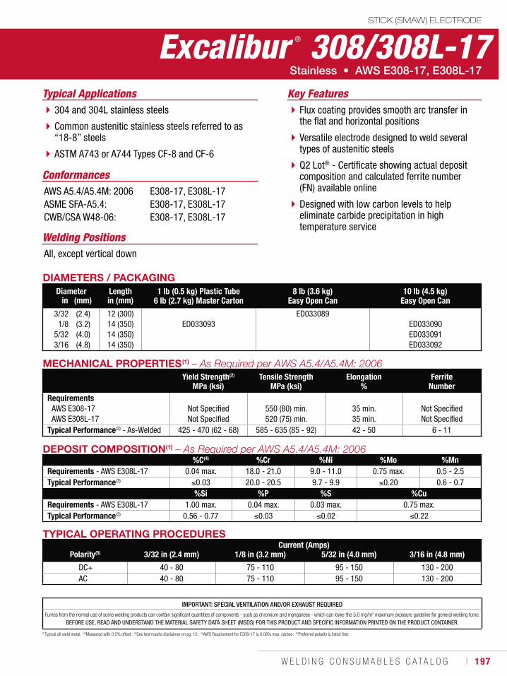
W E L D I N G C O N S U M A B L E S C A T A L O G ı 197
Excalibur ® 308/308L-17STICK (SMAW) ELECTRODE
Welding Positions
Typical Applications
All, except vertical down
304 and 304L stainless steels
Common austenitic stainless steels referred to as “18-8” steels
ASTM A743 or A744 Types CF-8 and CF-6
Flux coating provides smooth arc transfer in the flat and horizontal positions
Versatile electrode designed to weld several types of austenitic steels
Q2 Lot® - Certificate showing actual deposit composition and calculated ferrite number (FN) available online
Designed with low carbon levels to help eliminate carbide precipitation in high temperature service
Conformances
Key Features
AWS A5.4/A5.4M: 2006ASME SFA-A5.4:CWB/CSA W48-06:
E308-17, E308L-17E308-17, E308L-17E308-17, E308L-17
DIAMETERS / PACKAGINGDiameter Length 1 lb (0.5 kg) Plastic Tube
6 lb (2.7 kg) Master Carton8 lb (3.6 kg)
Easy Open Can10 lb (4.5 kg)
Easy Open Canin (mm) in (mm)
3/321/8
5/323/16
(2.4)(3.2)(4.0)(4.8)
12 (300)14 (350)14 (350)14 (350)
ED033093ED033089
ED033090ED033091ED033092
MECHANICAL PROPERTIES(1)
Yield Strength(2)
MPa (ksi)Tensile Strength
MPa (ksi)Elongation
%Ferrite
NumberRequirements
AWS E308-17AWS E308L-17
Not SpecifiedNot Specified
550 (80) min.520 (75) min.
35 min.35 min.
Not SpecifiedNot Specified
Typical Performance(3) - As-Welded 425 - 470 (62 - 68) 585 - 635 (85 - 92) 42 - 50 6 - 11
DEPOSIT COMPOSITION(1)
%C(4) %Cr %Ni %Mo %MnRequirements - AWS E308L-17 0.04 max. 18.0 - 21.0 9.0 - 11.0 0.75 max. 0.5 - 2.5Typical Performance(3) 0.03 20.0 - 20.5 9.7 - 9.9 0.20 0.6 - 0.7
%Si %P %S %CuRequirements - AWS E308L-17 1.00 max. 0.04 max. 0.03 max. 0.75 max.Typical Performance(3) 0.56 - 0.77 0.03 0.02 0.22
TYPICAL OPERATING PROCEDURESCurrent (Amps)
Polarity(5) 3/32 in (2.4 mm) 1/8 in (3.2 mm) 5/32 in (4.0 mm) 3/16 in (4.8 mm)
DC+ 40 - 80 75 - 110 95 - 150 130 - 200AC 40 - 80 75 - 110 95 - 150 130 - 200
(1)Typical all weld metal. (2)Measured with 0.2% offset. (3)See test results disclaimer on pg. 12. (4)AWS Requirement for E308-17 is 0.08% max. carbon. (5)Preferred polarity is listed first.
IMPORTANT: SPECIAL VENTILATION AND/OR EXHAUST REQUIRED
Fumes from the normal use of some welding products can contain significant quantities of components - such as chromium and manganese - which can lower the 5.0 mg/m3 maximum exposure guideline for general welding fume.
BEFORE USE, READ AND UNDERSTAND THE MATERIAL SAFETY DATA SHEET (MSDS) FOR THIS PRODUCT AND SPECIFIC INFORMATION PRINTED ON THE PRODUCT CONTAINER.
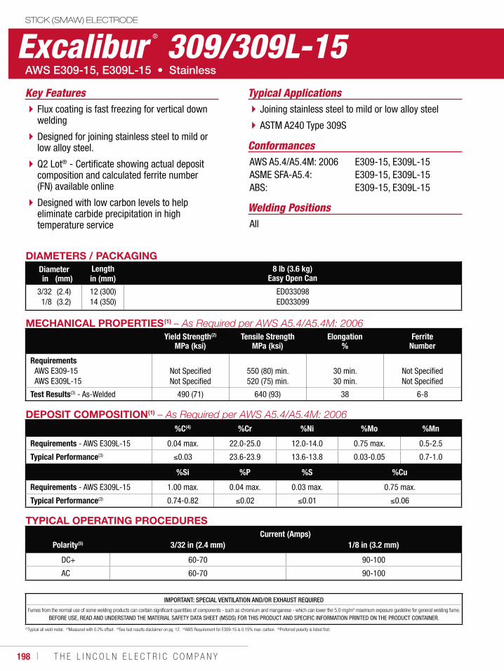
198 ı T H E L I N C O L N E L E C T R I C C O M P A N Y
Excalibur ® 309/309L-15STICK (SMAW) ELECTRODE
Welding Positions
Typical Applications
All
Joining stainless steel to mild or low alloy steel
ASTM A240 Type 309S
Flux coating is fast freezing for vertical down welding
Designed for joining stainless steel to mild or low alloy steel.
Q2 Lot® - Certificate showing actual deposit composition and calculated ferrite number (FN) available online
Designed with low carbon levels to help eliminate carbide precipitation in high temperature service
Conformances
Key Features
AWS A5.4/A5.4M: 2006ASME SFA-A5.4:ABS:
E309-15, E309L-15E309-15, E309L-15E309-15, E309L-15
DIAMETERS / PACKAGINGDiameter Length 8 lb (3.6 kg)
Easy Open Canin (mm) in (mm)
3/321/8
(2.4)(3.2)
12 (300)14 (350)
ED033098ED033099
MECHANICAL PROPERTIES(1)
Yield Strength(2)
MPa (ksi)Tensile Strength
MPa (ksi)Elongation
%Ferrite
Number
RequirementsAWS E309-15AWS E309L-15
Not SpecifiedNot Specified
550 (80) min.520 (75) min.
30 min.30 min.
Not SpecifiedNot Specified
Test Results(3) - As-Welded 490 (71) 640 (93) 38 6-8
DEPOSIT COMPOSITION(1)
%C(4) %Cr %Ni %Mo %Mn
Requirements - AWS E309L-15 0.04 max. 22.0-25.0 12.0-14.0 0.75 max. 0.5-2.5
Typical Performance(3) 0.03 23.6-23.9 13.6-13.8 0.03-0.05 0.7-1.0
%Si %P %S %Cu
Requirements - AWS E309L-15 1.00 max. 0.04 max. 0.03 max. 0.75 max.
Typical Performance(3) 0.74-0.82 0.02 0.01 0.06
TYPICAL OPERATING PROCEDURESCurrent (Amps)
Polarity(5) 3/32 in (2.4 mm) 1/8 in (3.2 mm)
DC+ 60-70 90-100
AC 60-70 90-100
(1)Typical all weld metal. (2)Measured with 0.2% offset. (3)See test results disclaimer on pg. 12. (4)AWS Requirement for E309-15 is 0.15% max. carbon. (5)Preferred polarity is listed first.
IMPORTANT: SPECIAL VENTILATION AND/OR EXHAUST REQUIRED
Fumes from the normal use of some welding products can contain significant quantities of components - such as chromium and manganese - which can lower the 5.0 mg/m3 maximum exposure guideline for general welding fume.
BEFORE USE, READ AND UNDERSTAND THE MATERIAL SAFETY DATA SHEET (MSDS) FOR THIS PRODUCT AND SPECIFIC INFORMATION PRINTED ON THE PRODUCT CONTAINER.
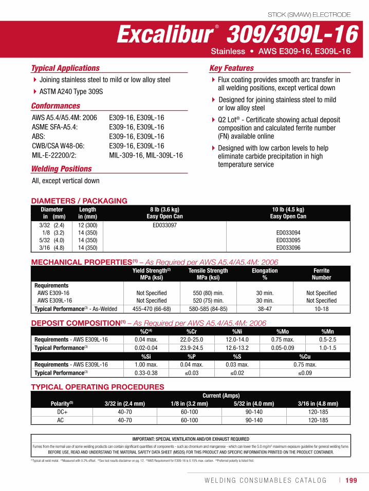
W E L D I N G C O N S U M A B L E S C A T A L O G ı 199
Excalibur ® 309/309L-16STICK (SMAW) ELECTRODE
Welding Positions
Typical Applications
All, except vertical down
Joining stainless steel to mild or low alloy steel
ASTM A240 Type 309S
Flux coating provides smooth arc transfer in all welding positions, except vertical down
Designed for joining stainless steel to mild or low alloy steel
Q2 Lot® - Certificate showing actual deposit composition and calculated ferrite number (FN) available online
Designed with low carbon levels to help eliminate carbide precipitation in high temperature service
Conformances
Key Features
AWS A5.4/A5.4M: 2006ASME SFA-A5.4:ABS:CWB/CSA W48-06:MIL-E-22200/2:
E309-16, E309L-16E309-16, E309L-16E309-16, E309L-16 E309-16, E309L-16MIL-309-16, MIL-309L-16
DIAMETERS / PACKAGINGDiameter Length 8 lb (3.6 kg)
Easy Open Can10 lb (4.5 kg)
Easy Open Canin (mm) in (mm)3/321/8
5/323/16
(2.4)(3.2)(4.0)(4.8)
12 (300)14 (350)14 (350)14 (350)
ED033097ED033094ED033095ED033096
MECHANICAL PROPERTIES(1)
Yield Strength(2)
MPa (ksi)Tensile Strength
MPa (ksi)Elongation
%Ferrite
NumberRequirements
AWS E309-16AWS E309L-16
Not SpecifiedNot Specified
550 (80) min.520 (75) min.
30 min.30 min.
Not SpecifiedNot Specified
Typical Performance(3) - As-Welded 455-470 (66-68) 580-585 (84-85) 38-47 10-18
DEPOSIT COMPOSITION(1)
%C(4) %Cr %Ni %Mo %MnRequirements - AWS E309L-16 0.04 max. 22.0-25.0 12.0-14.0 0.75 max. 0.5-2.5Typical Performance(3) 0.02-0.04 23.9-24.5 12.6-13.2 0.05-0.09 1.0-1.5
%Si %P %S %CuRequirements - AWS E309L-16 1.00 max. 0.04 max. 0.03 max. 0.75 max.Typical Performance(3) 0.33-0.38 0.03 0.02 0.09
TYPICAL OPERATING PROCEDURESCurrent (Amps)
Polarity(5) 3/32 in (2.4 mm) 1/8 in (3.2 mm) 5/32 in (4.0 mm) 3/16 in (4.8 mm)DC+ 40-70 60-100 90-140 120-185AC 40-70 60-100 90-140 120-185
(1)Typical all weld metal. (2)Measured with 0.2% offset. (3)See test results disclaimer on pg. 12. (4)AWS Requirement for E309-16 is 0.15% max. carbon. (5)Preferred polarity is listed first.
IMPORTANT: SPECIAL VENTILATION AND/OR EXHAUST REQUIRED
Fumes from the normal use of some welding products can contain significant quantities of components - such as chromium and manganese - which can lower the 5.0 mg/m3 maximum exposure guideline for general welding fume.
BEFORE USE, READ AND UNDERSTAND THE MATERIAL SAFETY DATA SHEET (MSDS) FOR THIS PRODUCT AND SPECIFIC INFORMATION PRINTED ON THE PRODUCT CONTAINER.
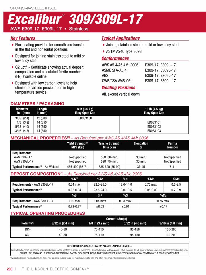
200 ı T H E L I N C O L N E L E C T R I C C O M P A N Y
Excalibur ® 309/309L-17STICK (SMAW) ELECTRODE
Welding Positions
Typical Applications
All, except vertical down
Joining stainless steel to mild or low alloy steel
ASTM A240 Type 309S
Flux coating provides for smooth arc transfer in the flat and horizontal positions
Designed for joining stainless steel to mild or low alloy steel
Q2 Lot® - Certificate showing actual deposit composition and calculated ferrite number (FN) available online
Designed with low carbon levels to help eliminate carbide precipitation in high temperature service
Conformances
Key Features
AWS A5.4/A5.4M: 2006ASME SFA-A5.4:ABS:CWB/CSA W48-06:
E309-17, E309L-17E309-17, E309L-17E309-17, E309L-17E309-17, E309L-17
DIAMETERS / PACKAGINGDiameter Length 8 lb (3.6 kg)
Easy Open Can10 lb (4.5 kg)
Easy Open Canin (mm) in (mm)
3/321/8
5/323/16
(2.4)(3.2)(4.0)(4.8)
12 (300)14 (350)14 (350)14 (350)
ED033100ED033101ED033102ED033103
MECHANICAL PROPERTIES(1)
Yield Strength(2)
MPa (ksi)Tensile Strength
MPa (ksi)Elongation
%Ferrite
Number
RequirementsAWS E309-17AWS E309L-17
Not SpecifiedNot Specified
550 (80) min.520 (75) min.
30 min.30 min.
Not SpecifiedNot Specified
Typical Performance(3) - As-Welded 455-490 (66-71) 585-620 (85-90) 37-45 7-11
DEPOSIT COMPOSITION(1)
%C(4) %Cr %Ni %Mo %Mn
Requirements - AWS E309L-17 0.04 max. 22.0-25.0 12.0-14.0 0.75 max. 0.5-2.5
Typical Performance(3) 0.02-0.04 23.5-24.0 13.0-13.5 0.05-0.09 0.7-0.9
%Si %P %S %Cu
Requirements - AWS E309L-17 1.00 max. 0.04 max. 0.03 max. 0.75 max.
Typical Performance(3) 0.72-0.77 0.03 0.01 0.17
TYPICAL OPERATING PROCEDURESCurrent (Amps)
Polarity(5) 3/32 in (2.4 mm) 1/8 in (3.2 mm) 5/32 in (4.0 mm) 3/16 in (4.8 mm)
DC+ 40-80 75-110 95-150 130-200
AC 40-80 75-110 95-150 130-200
(1)Typical all weld metal. (2)Measured with 0.2% offset. (3)See test results disclaimer on pg. 12. (4)AWS Requirement for E309-17 is 0.15% max. carbon. (5)Preferred polarity is listed first.
IMPORTANT: SPECIAL VENTILATION AND/OR EXHAUST REQUIRED
Fumes from the normal use of some welding products can contain significant quantities of components - such as chromium and manganese - which can lower the 5.0 mg/m3 maximum exposure guideline for general welding fume.
BEFORE USE, READ AND UNDERSTAND THE MATERIAL SAFETY DATA SHEET (MSDS) FOR THIS PRODUCT AND SPECIFIC INFORMATION PRINTED ON THE PRODUCT CONTAINER.
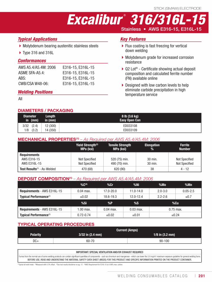
W E L D I N G C O N S U M A B L E S C A T A L O G ı 201
Excalibur ® 316/316L-15STICK (SMAW) ELECTRODE
Welding Positions
Typical Applications
All
Molybdenum bearing austenitic stainless steels
Type 316 and 316L
Flux coating is fast freezing for vertical down welding
Molybdenum grade for increased corrosion resistance
Q2 Lot® - Certificate showing actual deposit composition and calculated ferrite number (FN) available online
Designed with low carbon levels to help eliminate carbide precipitation in high temperature service
Conformances
Stainless • AWS E316-15, E316L-15
Key Features
AWS A5.4/A5.4M: 2006ASME SFA-A5.4:ABS:CWB/CSA W48-06:
E316-15, E316L-15E316-15, E316L-15E316-15, E316L-15E316-15, E316L-15
DIAMETERS / PACKAGINGDiameter Length 8 lb (3.6 kg)
Easy Open Canin (mm) in (mm)
3/321/8
(2.4)(3.2)
12 (300)14 (350)
ED033108ED033109
MECHANICAL PROPERTIES(1) – As Required per AWS A5.4/A5.4M: 2006Yield Strength(2)
MPa (ksi)Tensile Strength
MPa (ksi)Elongation
%Ferrite
Number
RequirementsAWS E316-15AWS E316L-15
Not SpecifiedNot Specified
520 (75) min.490 (70) min.
30 min.30 min.
Not SpecifiedNot Specified
Test Results(3) - As-Welded 470 (68) 620 (90) 38 4 - 12
DEPOSIT COMPOSITION(1) – As Required per AWS A5.4/A5.4M: 2006%C(4) %Cr %Ni %Mo %Mn
Requirements - AWS E316L-15 0.04 max. 17.0-20.0 11.0-14.0 2.0-3.0 0.05-2.5
Typical Performance(3) 0.02 18.6-19.3 12.0-12.4 2.2-2.6 0.7
%Si %P %S %Cu
Requirements - AWS E316L-15 1.00 max. 0.04 max. 0.03 max. 0.75 max.
Typical Performance(3) 0.72-0.74 0.02 0.01 0.24
TYPICAL OPERATING PROCEDURESCurrent (Amps)
Polarity 3/32 in (2.4 mm) 1/8 in (3.2 mm)
DC+ 60-70 90-100
(1)Typical all weld metal. (2)Measured with 0.2% offset. (3)See test results disclaimer on pg. 12. (4)AWS Requirement for E316-15 is 0.08% max. carbon.
IMPORTANT: SPECIAL VENTILATION AND/OR EXHAUST REQUIRED
Fumes from the normal use of some welding products can contain significant quantities of components - such as chromium and manganese - which can lower the 5.0 mg/m3 maximum exposure guideline for general welding fume.
BEFORE USE, READ AND UNDERSTAND THE MATERIAL SAFETY DATA SHEET (MSDS) FOR THIS PRODUCT AND SPECIFIC INFORMATION PRINTED ON THE PRODUCT CONTAINER.
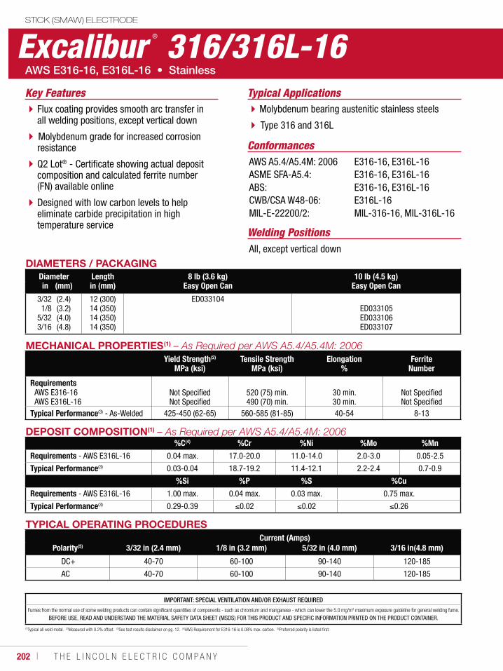
202 ı T H E L I N C O L N E L E C T R I C C O M P A N Y
Excalibur ® 316/316L-16STICK (SMAW) ELECTRODE
Welding Positions
Typical Applications
All, except vertical down
Molybdenum bearing austenitic stainless steels
Type 316 and 316L
Flux coating provides smooth arc transfer in all welding positions, except vertical down
Molybdenum grade for increased corrosion resistance
Q2 Lot® - Certificate showing actual deposit composition and calculated ferrite number (FN) available online
Designed with low carbon levels to help eliminate carbide precipitation in high temperature service
Conformances
Key Features
AWS A5.4/A5.4M: 2006ASME SFA-A5.4:ABS:CWB/CSA W48-06:MIL-E-22200/2:
E316-16, E316L-16E316-16, E316L-16E316-16, E316L-16 E316L-16MIL-316-16, MIL-316L-16
DIAMETERS / PACKAGINGDiameter Length 8 lb (3.6 kg)
Easy Open Can10 lb (4.5 kg)
Easy Open Canin (mm) in (mm)
3/321/8
5/323/16
(2.4)(3.2)(4.0)(4.8)
12 (300)14 (350)14 (350)14 (350)
ED033104ED033105ED033106ED033107
MECHANICAL PROPERTIES(1)
Yield Strength(2)
MPa (ksi)Tensile Strength
MPa (ksi)Elongation
%Ferrite
Number
RequirementsAWS E316-16AWS E316L-16
Not SpecifiedNot Specified
520 (75) min.490 (70) min.
30 min.30 min.
Not SpecifiedNot Specified
Typical Performance(3) - As-Welded 425-450 (62-65) 560-585 (81-85) 40-54 8-13
DEPOSIT COMPOSITION(1)
%C(4) %Cr %Ni %Mo %Mn
Requirements - AWS E316L-16 0.04 max. 17.0-20.0 11.0-14.0 2.0-3.0 0.05-2.5
Typical Performance(3) 0.03-0.04 18.7-19.2 11.4-12.1 2.2-2.4 0.7-0.9
%Si %P %S %Cu
Requirements - AWS E316L-16 1.00 max. 0.04 max. 0.03 max. 0.75 max.
Typical Performance(3) 0.29-0.39 0.02 0.02 0.26
TYPICAL OPERATING PROCEDURESCurrent (Amps)
Polarity(5) 3/32 in (2.4 mm) 1/8 in (3.2 mm) 5/32 in (4.0 mm) 3/16 in(4.8 mm)
DC+ 40-70 60-100 90-140 120-185
AC 40-70 60-100 90-140 120-185
(1)Typical all weld metal. (2)Measured with 0.2% offset. (3)See test results disclaimer on pg. 12. (4)AWS Requirement for E316-16 is 0.08% max. carbon. (5)Preferred polarity is listed first.
IMPORTANT: SPECIAL VENTILATION AND/OR EXHAUST REQUIRED
Fumes from the normal use of some welding products can contain significant quantities of components - such as chromium and manganese - which can lower the 5.0 mg/m3 maximum exposure guideline for general welding fume.
BEFORE USE, READ AND UNDERSTAND THE MATERIAL SAFETY DATA SHEET (MSDS) FOR THIS PRODUCT AND SPECIFIC INFORMATION PRINTED ON THE PRODUCT CONTAINER.
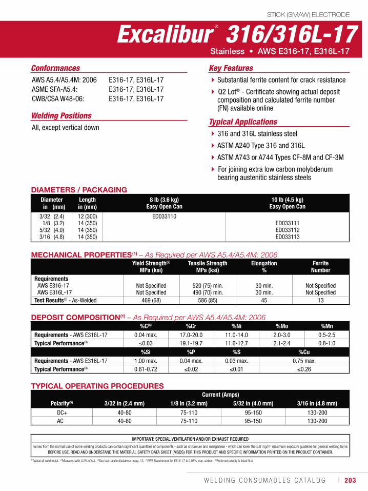
W E L D I N G C O N S U M A B L E S C A T A L O G ı 203
IMPORTANT: SPECIAL VENTILATION AND/OR EXHAUST REQUIRED
Fumes from the normal use of some welding products can contain significant quantities of components - such as chromium and manganese - which can lower the 5.0 mg/m3 maximum exposure guideline for general welding fume.
BEFORE USE, READ AND UNDERSTAND THE MATERIAL SAFETY DATA SHEET (MSDS) FOR THIS PRODUCT AND SPECIFIC INFORMATION PRINTED ON THE PRODUCT CONTAINER.
Excalibur ® 316/316L-17STICK (SMAW) ELECTRODE
Welding PositionsTypical Applications
All, except vertical down316 and 316L stainless steel
ASTM A240 Type 316 and 316L
ASTM A743 or A744 Types CF-8M and CF-3M
For joining extra low carbon molybdenum bearing austenitic stainless steels
Substantial ferrite content for crack resistance
Q2 Lot® - Certificate showing actual deposit composition and calculated ferrite number (FN) available online
Conformances Key FeaturesAWS A5.4/A5.4M: 2006ASME SFA-A5.4:CWB/CSA W48-06:
E316-17, E316L-17E316-17, E316L-17E316-17, E316L-17
DIAMETERS / PACKAGINGDiameter Length 8 lb (3.6 kg)
Easy Open Can10 lb (4.5 kg)
Easy Open Canin (mm) in (mm)
3/321/8
5/323/16
(2.4)(3.2)(4.0)(4.8)
12 (300)14 (350)14 (350)14 (350)
ED033110ED033111ED033112ED033113
MECHANICAL PROPERTIES(1)
Yield Strength(2)
MPa (ksi)Tensile Strength
MPa (ksi)Elongation
%Ferrite
NumberRequirements
AWS E316-17AWS E316L-17
Not SpecifiedNot Specified
520 (75) min.490 (70) min.
30 min.30 min.
Not SpecifiedNot Specified
Test Results(3) - As-Welded 469 (68) 586 (85) 45 13
DEPOSIT COMPOSITION(1)
%C(4) %Cr %Ni %Mo %MnRequirements - AWS E316L-17 0.04 max. 17.0-20.0 11.0-14.0 2.0-3.0 0.5-2.5Typical Performance(3) 0.03 19.1-19.7 11.6-12.7 2.1-2.4 0.8-1.0
%Si %P %S %CuRequirements - AWS E316L-17 1.00 max. 0.04 max. 0.03 max. 0.75 max.Typical Performance(3) 0.61-0.72 0.02 0.01 0.26
TYPICAL OPERATING PROCEDURESCurrent (Amps)
Polarity(5) 3/32 in (2.4 mm) 1/8 in (3.2 mm) 5/32 in (4.0 mm) 3/16 in (4.8 mm)
DC+ 40-80 75-110 95-150 130-200AC 40-80 75-110 95-150 130-200
(1)Typical all weld metal. (2)Measured with 0.2% offset. (3)See test results disclaimer on pg. 12. (4)AWS Requirement for E316-17 is 0.08% max. carbon. (5)Preferred polarity is listed first.
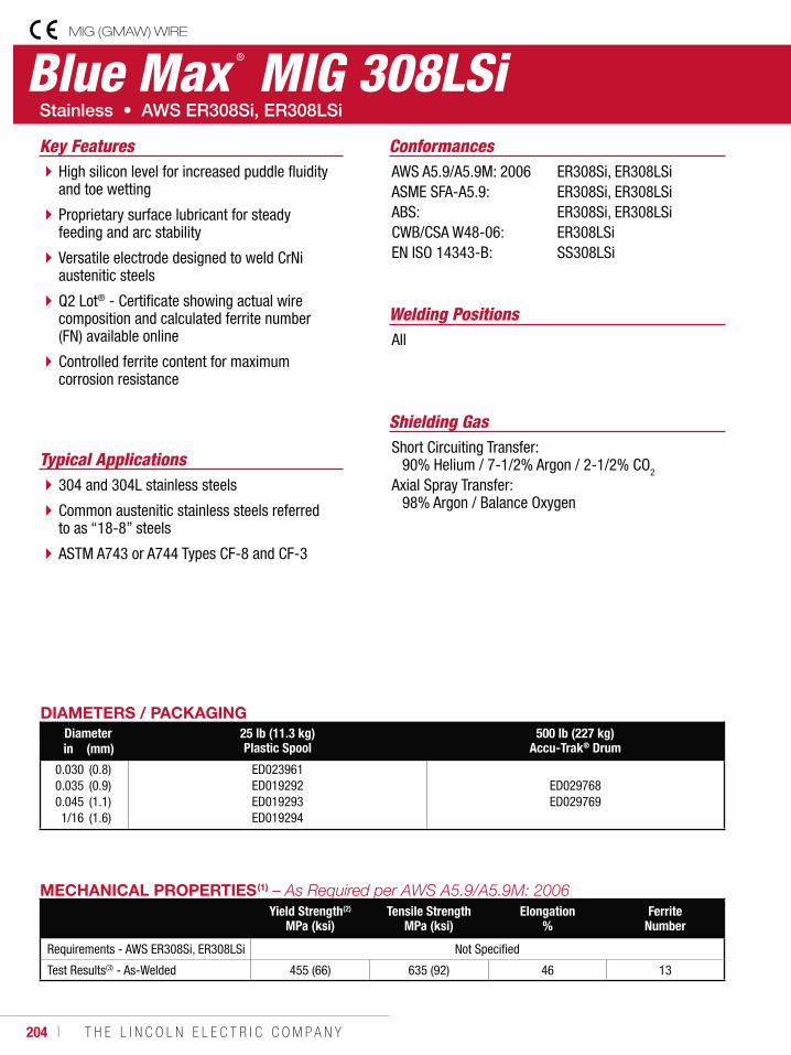
204 ı T H E L I N C O L N E L E C T R I C C O M P A N Y
Blue Max ® MIG 308LSiMIG (GMAW) WIRE
Welding Positions
Typical Applications
All
304 and 304L stainless steels
Common austenitic stainless steels referred to as “18-8” steels
ASTM A743 or A744 Types CF-8 and CF-3
High silicon level for increased puddle fluidity and toe wetting
Proprietary surface lubricant for steady feeding and arc stability
Versatile electrode designed to weld CrNi austenitic steels
Q2 Lot® - Certificate showing actual wire composition and calculated ferrite number (FN) available online
Controlled ferrite content for maximum corrosion resistance
Conformances
Shielding GasShort Circuiting Transfer: 90% Helium / 7-1/2% Argon / 2-1/2% CO2 Axial Spray Transfer: 98% Argon / Balance Oxygen
Key FeaturesAWS A5.9/A5.9M: 2006ASME SFA-A5.9:ABS:CWB/CSA W48-06:EN ISO 14343-B:
ER308Si, ER308LSi ER308Si, ER308LSi ER308Si, ER308LSiER308LSiSS308LSi
DIAMETERS / PACKAGINGDiameter 25 lb (11.3 kg)
Plastic Spool500 lb (227 kg)
Accu-Trak® Drumin (mm)
0.0300.0350.0451/16
(0.8)(0.9)(1.1)(1.6)
ED023961ED019292ED019293ED019294
ED029768ED029769
MECHANICAL PROPERTIES(1)
Yield Strength(2)
MPa (ksi)Tensile Strength
MPa (ksi)Elongation
%Ferrite
Number
Requirements - AWS ER308Si, ER308LSi Not Specified
Test Results(3) - As-Welded 455 (66) 635 (92) 46 13
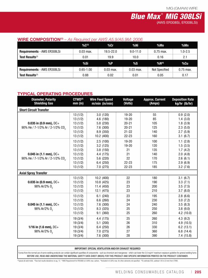
W E L D I N G C O N S U M A B L E S C A T A L O G ı 205
Blue Max ® MIG 308LSiMIG (GMAW) WIRE
(AWS ER308Si, ER308LSi)
(1)Typical all weld metal. (2)See test results disclaimer on pg. 12. (3)AWS Requirement for ER308Si is 0.08% max. carbon. (4)Included in 0.50% max. for other elements not specified. (5)To estimate ESO, subtract 1/8 in (3 mm) from CTWD.
TYPICAL OPERATING PROCEDURESDiameter, Polarity
Shielding GasCTWD(5)
mm (in)Wire Feed Speed Voltage
(Volts)Approx. Current
(Amps)Deposition Rate
m/min (in/min) kg/hr (lb/hr)
Short Circuit Transfer
0.035 in (0.9 mm), DC+90% He / 7-1/2% Ar / 2-1/2% CO2
13 (1/2)13 (1/2)13 (1/2)13 (1/2)13 (1/2)13 (1/2)
3.04.65.87.68.9
10.2
(120)(180)(230)(300)(350)(400)
19-20 19-20 20-21 20-21 21-22 22-23
5585
105125140160
0.91.41.82.32.73.1
(2.0)(3.0)(3.9)(5.0)(5.9)(6.7)
0.045 in (1.1 mm), DC+ 90% He / 7-1/2% Ar / 2-1/2% CO
2
13 (1/2)13 (1/2)13 (1/2)13 (1/2)13 (1/2)13 (1/2)13 (1/2)
2.53.23.84.45.66.47.0
(100)(125)(150)(175)(220)(250)(275)
19-2019-20
212122
22-2322-23
100120135140170175185
1.11.51.72.02.62.93.2
(2.8)(3.5)(4.2)(4.8)(6.1)(6.9)(7.6)
Axial Spray Transfer
0.035 in (0.9 mm), DC+ 98% Ar/2% O
2
13 (1/2)13 (1/2)13 (1/2)13 (1/2)
10.210.811.412.1
(400)(425)(450)(475)
22232323
180190200210
3.13.33.53.7
(6.7)(7.1)(7.5)(8.0)
0.045 in (1.1 mm), DC+ 98% Ar/2% O
2
13 (1/2)13 (1/2)13 (1/2)13 (1/2)13 (1/2)
6.16.67.68.39.1
(240)(260)(300)(325)(360)
2324242525
195230240250260
2.83.03.53.84.2
(6.6)(7.2)(8.3)(9.0)(10.0)
1/16 in (1.6 mm), DC+ 98% Ar/2% O
2
19 (3/4)19 (3/4)19 (3/4)19 (3/4)19 (3/4)
4.45.16.47.07.6
(175)(200)(250)(275)(300)
2526262728
260310330360390
4.34.96.26.87.4
(9.2)(10.5)(13.1)(14.4)(15.8)
WIRE COMPOSITION(1)
%C(3) %Cr %Ni %Mo %Mn
Requirements - AWS ER308LSi 0.03 max. 19.5-22.0 9.0-11.0 0.75 max. 1.0-2.5
Test Results(3) 0.01 19.9 10.0 0.16 2.1
%Si %P %S %N(4) %Cu
Requirements - AWS ER308LSi 0.65-1.00 0.03 max. 0.03 max. Not Specified 0.75 max.
Test Results(3) 0.88 0.02 0.01 0.05 0.17
IMPORTANT: SPECIAL VENTILATION AND/OR EXHAUST REQUIRED
Fumes from the normal use of some welding products can contain significant quantities of components - such as chromium and manganese - which can lower the 5.0 mg/m3 maximum exposure guideline for general welding fume.
BEFORE USE, READ AND UNDERSTAND THE MATERIAL SAFETY DATA SHEET (MSDS) FOR THIS PRODUCT AND SPECIFIC INFORMATION PRINTED ON THE PRODUCT CONTAINER.
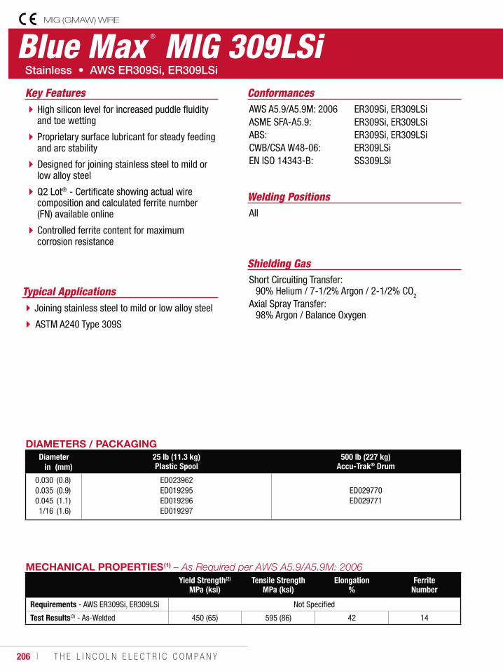
206 ı T H E L I N C O L N E L E C T R I C C O M P A N Y
Blue Max ® MIG 309LSiMIG (GMAW) WIRE
Welding Positions
Typical Applications
All
Joining stainless steel to mild or low alloy steel
ASTM A240 Type 309S
High silicon level for increased puddle fluidity and toe wetting
Proprietary surface lubricant for steady feeding and arc stability
Designed for joining stainless steel to mild or low alloy steel
Q2 Lot® - Certificate showing actual wire composition and calculated ferrite number (FN) available online
Controlled ferrite content for maximum corrosion resistance
Conformances
Shielding GasShort Circuiting Transfer: 90% Helium / 7-1/2% Argon / 2-1/2% CO2 Axial Spray Transfer: 98% Argon / Balance Oxygen
Key FeaturesAWS A5.9/A5.9M: 2006ASME SFA-A5.9:ABS:CWB/CSA W48-06:EN ISO 14343-B:
ER309Si, ER309LSi ER309Si, ER309LSiER309Si, ER309LSiER309LSiSS309LSi
DIAMETERS / PACKAGINGDiameter 25 lb (11.3 kg)
Plastic Spool500 lb (227 kg)
Accu-Trak® Drumin (mm)
0.0300.0350.0451/16
(0.8)(0.9)(1.1)(1.6)
ED023962 ED019295ED019296ED019297
ED029770ED029771
MECHANICAL PROPERTIES(1)
Yield Strength(2)
MPa (ksi)Tensile Strength
MPa (ksi)Elongation
%Ferrite
Number
Requirements - AWS ER309Si, ER309LSi Not Specified
Test Results(3) - As-Welded 450 (65) 595 (86) 42 14
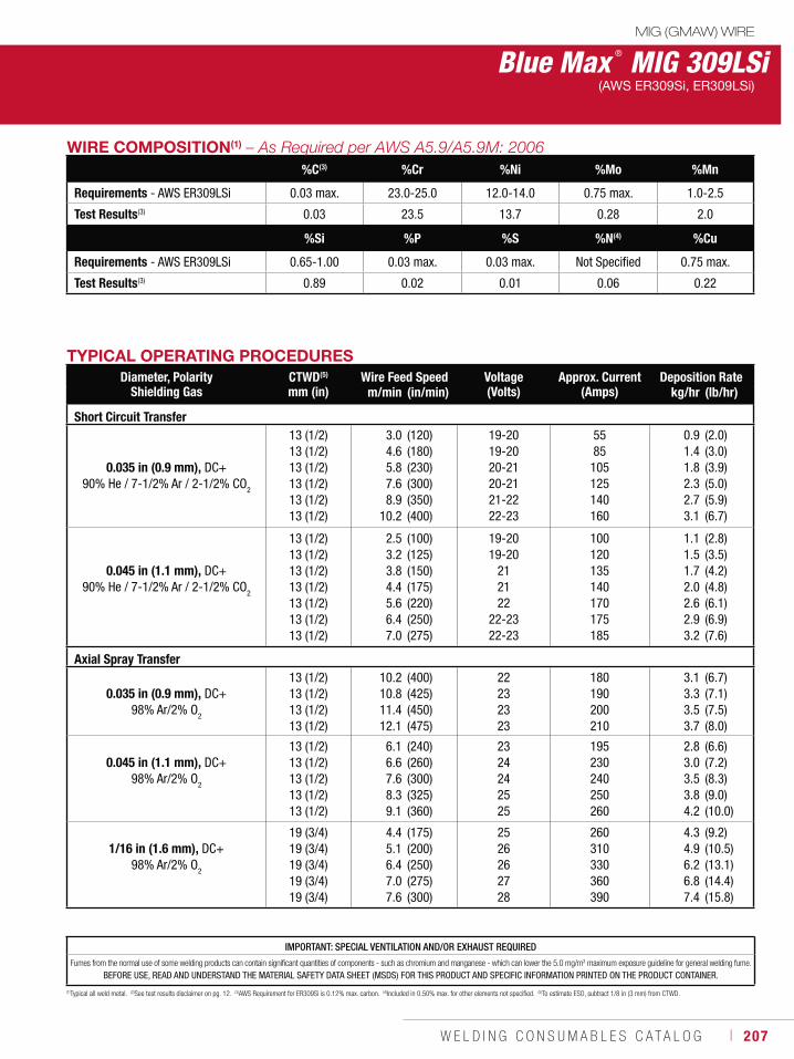
W E L D I N G C O N S U M A B L E S C A T A L O G ı 207
Blue Max ® MIG 309LSiMIG (GMAW) WIRE
(AWS ER309Si, ER309LSi)
(1)Typical all weld metal. (2)See test results disclaimer on pg. 12. (3)AWS Requirement for ER309Si is 0.12% max. carbon. (4)Included in 0.50% max. for other elements not specified. (5)To estimate ESO, subtract 1/8 in (3 mm) from CTWD.
TYPICAL OPERATING PROCEDURESDiameter, Polarity
Shielding GasCTWD(5)
mm (in)Wire Feed Speed Voltage
(Volts)Approx. Current
(Amps)Deposition Rate
m/min (in/min) kg/hr (lb/hr)
Short Circuit Transfer
0.035 in (0.9 mm), DC+90% He / 7-1/2% Ar / 2-1/2% CO
2
13 (1/2)13 (1/2)13 (1/2)13 (1/2)13 (1/2)13 (1/2)
3.04.65.87.68.9
10.2
(120)(180)(230)(300)(350)(400)
19-20 19-20 20-21 20-21 21-22 22-23
5585
105125140160
0.91.41.82.32.73.1
(2.0)(3.0)(3.9)(5.0)(5.9)(6.7)
0.045 in (1.1 mm), DC+ 90% He / 7-1/2% Ar / 2-1/2% CO
2
13 (1/2)13 (1/2)13 (1/2)13 (1/2)13 (1/2)13 (1/2)13 (1/2)
2.53.23.84.45.66.47.0
(100)(125)(150)(175)(220)(250)(275)
19-2019-20
212122
22-2322-23
100120135140170175185
1.11.51.72.02.62.93.2
(2.8)(3.5)(4.2)(4.8)(6.1)(6.9)(7.6)
Axial Spray Transfer
0.035 in (0.9 mm), DC+ 98% Ar/2% O
2
13 (1/2)13 (1/2)13 (1/2)13 (1/2)
10.210.811.412.1
(400)(425)(450)(475)
22232323
180190200210
3.13.33.53.7
(6.7)(7.1)(7.5)(8.0)
0.045 in (1.1 mm), DC+ 98% Ar/2% O
2
13 (1/2)13 (1/2)13 (1/2)13 (1/2)13 (1/2)
6.16.67.68.39.1
(240)(260)(300)(325)(360)
2324242525
195230240250260
2.83.03.53.84.2
(6.6)(7.2)(8.3)(9.0)(10.0)
1/16 in (1.6 mm), DC+ 98% Ar/2% O
2
19 (3/4)19 (3/4)19 (3/4)19 (3/4)19 (3/4)
4.45.16.47.07.6
(175)(200)(250)(275)(300)
2526262728
260310330360390
4.34.96.26.87.4
(9.2)(10.5)(13.1)(14.4)(15.8)
WIRE COMPOSITION(1)
%C(3) %Cr %Ni %Mo %Mn
Requirements - AWS ER309LSi 0.03 max. 23.0-25.0 12.0-14.0 0.75 max. 1.0-2.5
Test Results(3) 0.03 23.5 13.7 0.28 2.0
%Si %P %S %N(4) %Cu
Requirements - AWS ER309LSi 0.65-1.00 0.03 max. 0.03 max. Not Specified 0.75 max.
Test Results(3) 0.89 0.02 0.01 0.06 0.22
IMPORTANT: SPECIAL VENTILATION AND/OR EXHAUST REQUIRED
Fumes from the normal use of some welding products can contain significant quantities of components - such as chromium and manganese - which can lower the 5.0 mg/m3 maximum exposure guideline for general welding fume.
BEFORE USE, READ AND UNDERSTAND THE MATERIAL SAFETY DATA SHEET (MSDS) FOR THIS PRODUCT AND SPECIFIC INFORMATION PRINTED ON THE PRODUCT CONTAINER.
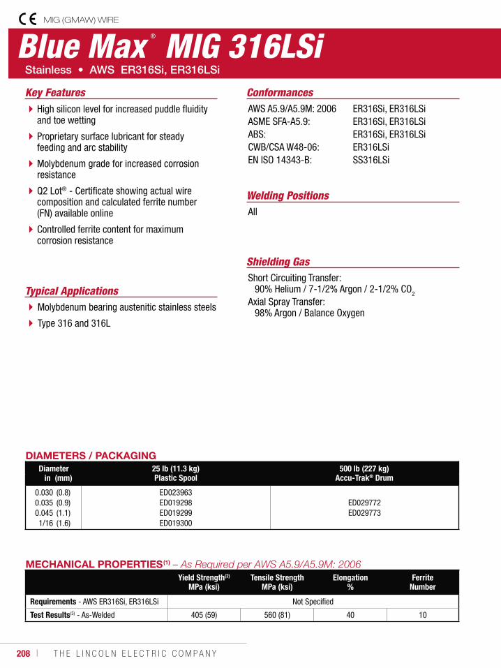
208 ı T H E L I N C O L N E L E C T R I C C O M P A N Y
Blue Max ® MIG 316LSiMIG (GMAW) WIRE
Welding Positions
Typical Applications
All
Molybdenum bearing austenitic stainless steels
Type 316 and 316L
High silicon level for increased puddle fluidity and toe wetting
Proprietary surface lubricant for steady feeding and arc stability
Molybdenum grade for increased corrosion resistance
Q2 Lot® - Certificate showing actual wirecomposition and calculated ferrite number (FN) available online
Controlled ferrite content for maximum corrosion resistance
Conformances
Shielding GasShort Circuiting Transfer: 90% Helium / 7-1/2% Argon / 2-1/2% CO2
Axial Spray Transfer: 98% Argon / Balance Oxygen
Key FeaturesAWS A5.9/A5.9M: 2006ASME SFA-A5.9:ABS:CWB/CSA W48-06:EN ISO 14343-B:
ER316Si, ER316LSiER316Si, ER316LSiER316Si, ER316LSiER316LSiSS316LSi
DIAMETERS / PACKAGINGDiameter 25 lb (11.3 kg)
Plastic Spool500 lb (227 kg)
Accu-Trak® Drumin (mm)
0.0300.0350.0451/16
(0.8)(0.9)(1.1)(1.6)
ED023963ED019298ED019299ED019300
ED029772ED029773
MECHANICAL PROPERTIES(1)
Yield Strength(2)
MPa (ksi)Tensile Strength
MPa (ksi)Elongation
%Ferrite
Number
Requirements - AWS ER316Si, ER316LSi Not Specified
Test Results(3) - As-Welded 405 (59) 560 (81) 40 10
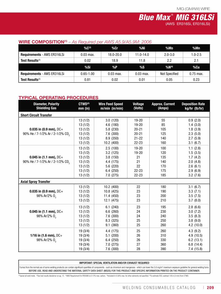
W E L D I N G C O N S U M A B L E S C A T A L O G ı 209
Blue Max ® MIG 316LSiMIG (GMAW) WIRE
(AWS ER316Si, ER316LSi)
(1)Typical all weld metal. (2)See test results disclaimer on pg. 12. (3)AWS Requirement for ER309Si is 0.12% max. carbon. (4)Included in 0.50% max. for other elements not specified. (5)To estimate ESO, subtract 1/8 in (3 mm) from CTWD.
TYPICAL OPERATING PROCEDURESDiameter, Polarity
Shielding GasCTWD(5) Wire Feed Speed Voltage
(Volts)Approx. Current
(Amps)Deposition Rate
mm (in) m/min (in/min) kg/hr (lb/hr)
Short Circuit Transfer
0.035 in (0.9 mm), DC+90% He / 7-1/2% Ar / 2-1/2% CO2
13 (1/2)13 (1/2)13 (1/2)13 (1/2)13 (1/2)13 (1/2)
3.04.65.87.68.9
10.2
(120)(180)(230)(300)(350)(400)
19-20 19-20 20-21 20-21 21-22 22-23
5585
105125140160
0.91.41.82.32.73.1
(2.0)(3.0)(3.9)(5.0)(5.9)(6.7)
0.045 in (1.1 mm), DC+ 90% He / 7-1/2% Ar / 2-1/2% CO
2
13 (1/2)13 (1/2)13 (1/2)13 (1/2)13 (1/2)13 (1/2)13 (1/2)
2.53.23.84.45.66.47.0
(100)(125)(150)(175)(220)(250)(275)
19-2019-20
212122
22-2322-23
100120135140170175185
1.11.51.72.02.62.93.2
(2.8)(3.5)(4.2)(4.8)(6.1)(6.9)(7.6)
Axial Spray Transfer
0.035 in (0.9 mm), DC+ 98% Ar/2% O
2
13 (1/2)13 (1/2)13 (1/2)13 (1/2)
10.210.811.412.1
(400)(425)(450)(475)
22232323
180190200210
3.13.33.53.7
(6.7)(7.1)(7.5)(8.0)
0.045 in (1.1 mm), DC+ 98% Ar/2% O
2
13 (1/2)13 (1/2)13 (1/2)13 (1/2)13 (1/2)
6.16.67.68.39.1
(240)(260)(300)(325)(360)
2324242525
195230240250260
2.83.03.53.84.2
(6.6)(7.2)(8.3)(9.0)(10.0)
1/16 in (1.6 mm), DC+ 98% Ar/2% O
2
19 (3/4)19 (3/4)19 (3/4)19 (3/4)19 (3/4)
4.45.16.47.07.6
(175)(200)(250)(275)(300)
2526262728
260310330360390
4.34.96.26.87.4
(9.2)(10.5)(13.1)(14.4)(15.8)
WIRE COMPOSITION(1)
%C(3) %Cr %Ni %Mo %Mn
Requirements - AWS ER316LSi 0.03 max. 18.0-20.0 11.0-14.0 2.0-3.0 1.0-2.5
Test Results(3) 0.02 18.9 11.8 2.2 2.1
%Si %P %S %N(4) %Cu
Requirements - AWS ER316LSi 0.65-1.00 0.03 max. 0.03 max. Not Specified 0.75 max.
Test Results(3) 0.81 0.02 0.01 0.05 0.23
IMPORTANT: SPECIAL VENTILATION AND/OR EXHAUST REQUIRED
Fumes from the normal use of some welding products can contain significant quantities of components - such as chromium and manganese - which can lower the 5.0 mg/m3 maximum exposure guideline for general welding fume.
BEFORE USE, READ AND UNDERSTAND THE MATERIAL SAFETY DATA SHEET (MSDS) FOR THIS PRODUCT AND SPECIFIC INFORMATION PRINTED ON THE PRODUCT CONTAINER.
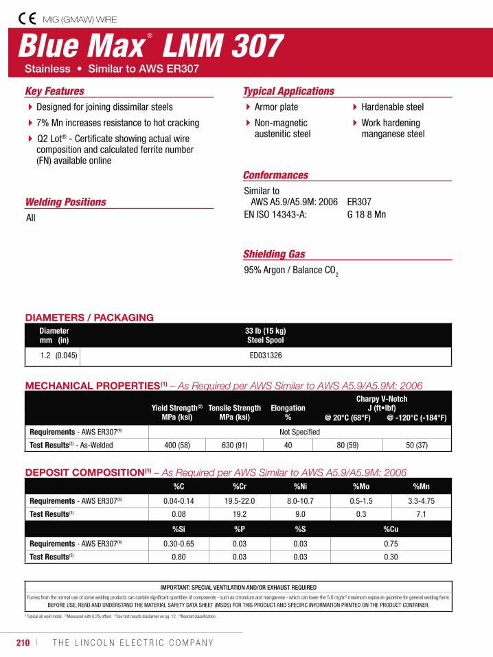
210 ı T H E L I N C O L N E L E C T R I C C O M P A N Y
DEPOSIT COMPOSITION(1)
%C %Cr %Ni %Mo %Mn
Requirements - AWS ER307(4) 0.04-0.14 19.5-22.0 8.0-10.7 0.5-1.5 3.3-4.75
Test Results(3) 0.08 19.2 9.0 0.3 7.1
%Si %P %S %Cu
Requirements - AWS ER307(4) 0.30-0.65 0.03 0.03 0.75
Test Results(3) 0.80 0.03 0.03 0.30
(1)Typical all weld metal. (2)Measured with 0.2% offset. (3)See test results disclaimer on pg. 12. (4)Nearest classification.
Blue Max ® LNM 307MIG (GMAW) WIRE
Welding Positions
Typical Applications
All
Armor plate
Non-magnetic austenitic steel
Hardenable steel
Work hardening manganese steel
Designed for joining dissimilar steels
7% Mn increases resistance to hot cracking
Q2 Lot® - Certificate showing actual wire composition and calculated ferrite number (FN) available online
Conformances
Shielding Gas95% Argon / Balance CO2
Key Features
Similar to AWS A5.9/A5.9M: 2006EN ISO 14343-A:
ER307G 18 8 Mn
DIAMETERS / PACKAGINGDiameter 33 lb (15 kg)
Steel Spoolmm (in)
1.2 (0.045) ED031326
MECHANICAL PROPERTIES(1)
Yield Strength(2)
MPa (ksi)Tensile Strength
MPa (ksi)Elongation
%
Charpy V-NotchJ (ft•lbf)
@ 20°C (68°F) @ -120°C (-184°F)
Requirements - AWS ER307(4) Not Specified
Test Results(3) - As-Welded 400 (58) 630 (91) 40 80 (59) 50 (37)
IMPORTANT: SPECIAL VENTILATION AND/OR EXHAUST REQUIRED
Fumes from the normal use of some welding products can contain significant quantities of components - such as chromium and manganese - which can lower the 5.0 mg/m3 maximum exposure guideline for general welding fume.
BEFORE USE, READ AND UNDERSTAND THE MATERIAL SAFETY DATA SHEET (MSDS) FOR THIS PRODUCT AND SPECIFIC INFORMATION PRINTED ON THE PRODUCT CONTAINER.
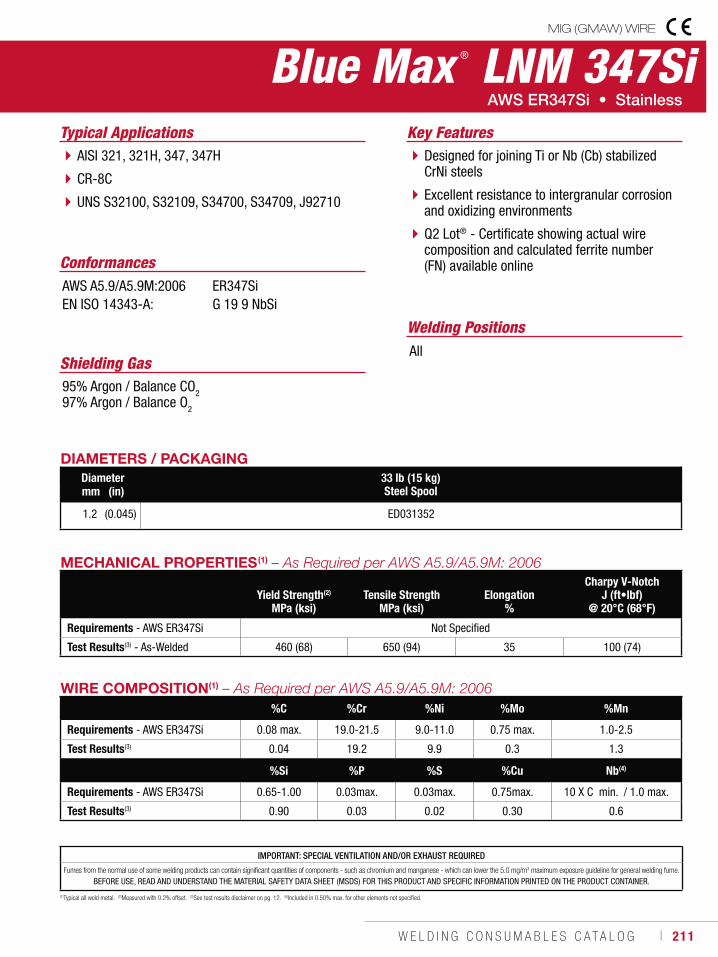
W E L D I N G C O N S U M A B L E S C A T A L O G ı 211
IMPORTANT: SPECIAL VENTILATION AND/OR EXHAUST REQUIRED
Fumes from the normal use of some welding products can contain significant quantities of components - such as chromium and manganese - which can lower the 5.0 mg/m3 maximum exposure guideline for general welding fume.
BEFORE USE, READ AND UNDERSTAND THE MATERIAL SAFETY DATA SHEET (MSDS) FOR THIS PRODUCT AND SPECIFIC INFORMATION PRINTED ON THE PRODUCT CONTAINER.
WIRE COMPOSITION(1)
%C %Cr %Ni %Mo %Mn
Requirements - AWS ER347Si 0.08 max. 19.0-21.5 9.0-11.0 0.75 max. 1.0-2.5
Test Results(3) 0.04 19.2 9.9 0.3 1.3
%Si %P %S %Cu Nb(4)
Requirements - AWS ER347Si 0.65-1.00 0.03max. 0.03max. 0.75max. 10 X C min. / 1.0 max.
Test Results(3) 0.90 0.03 0.02 0.30 0.6
(1)Typical all weld metal. (2)Measured with 0.2% offset. (3)See test results disclaimer on pg. 12. (4)Included in 0.50% max. for other elements not specified.
Blue Max ® LNM 347SiMIG (GMAW) WIRE
Welding Positions
Typical Applications
All
AISI 321, 321H, 347, 347H
CR-8C
UNS S32100, S32109, S34700, S34709, J92710
Designed for joining Ti or Nb (Cb) stabilized CrNi steels
Excellent resistance to intergranular corrosion and oxidizing environments
Q2 Lot® - Certificate showing actual wire composition and calculated ferrite number (FN) available onlineConformances
Shielding Gas95% Argon / Balance CO297% Argon / Balance O2
Key Features
AWS A5.9/A5.9M:2006EN ISO 14343-A:
ER347SiG 19 9 NbSi
DIAMETERS / PACKAGINGDiameter 33 lb (15 kg)
Steel Spoolmm (in)
1.2 (0.045) ED031352
MECHANICAL PROPERTIES(1)
Yield Strength(2)
MPa (ksi)Tensile Strength
MPa (ksi)Elongation
%
Charpy V-NotchJ (ft•lbf)
@ 20°C (68°F)
Requirements - AWS ER347Si Not Specified
Test Results(3) - As-Welded 460 (68) 650 (94) 35 100 (74)
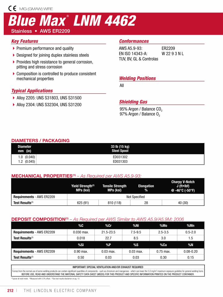
212 ı T H E L I N C O L N E L E C T R I C C O M P A N Y
IMPORTANT: SPECIAL VENTILATION AND/OR EXHAUST REQUIREDFumes from the normal use of some welding products can contain significant quantities of components - such as chromium and manganese - which can lower the 5.0 mg/m3 maximum exposure guideline for general welding fume.
BEFORE USE, READ AND UNDERSTAND THE MATERIAL SAFETY DATA SHEET (MSDS) FOR THIS PRODUCT AND SPECIFIC INFORMATION PRINTED ON THE PRODUCT CONTAINER.
DEPOSIT COMPOSITION(1)
%C %Cr %Ni %Mo %Mn
Requirements - AWS ER2209 0.030 max. 21.5-23.5 7.5-9.5 2.5-3.5 0.5-2.0
Test Results(3) 0.018 22.7 8.5 3.0 1.5
%Si %P %S %Cu %N
Requirements - AWS ER2209 0.90 max. 0.03 max. 0.03 max. 0.75 max. 0.08-0.20
Test Results(3) 0.50 0.03 0.03 0.30 0.15
(1)Typical all weld metal. (2)Measured with 0.2% offset. (3)See test results disclaimer on pg. 12.
Blue Max ® LNM 4462MIG (GMAW) WIRE
Welding Positions
Typical ApplicationsAll
Alloy 2205: UNS S31803, UNS S31500
Alloy 2304: UNS S32304, UNS S31200
Premium performance and quality
Designed for joining duplex stainless steels
Provides high resistance to general corrosion, pitting and stress corrosion
Composition is controlled to produce consistent mechanical properties
Conformances
Shielding Gas95% Argon / Balance CO2
97% Argon / Balance O2
Key FeaturesAWS A5.9-93:EN ISO 14343-A: TUV, BV, GL & Controlas
ER2209W 22 9 3 N L
DIAMETERS / PACKAGINGDiameter 33 lb (15 kg)
Steel Spoolmm (in)
1.01.2
(0.040)(0.045)
ED031302ED031303
MECHANICAL PROPERTIES(1)
Yield Strength(2)
MPa (ksi)Tensile Strength
MPa (ksi)Elongation
%
Charpy V-NotchJ (ft•lbf)
@ -46°C (-50°F)
Requirements - AWS ER2209 Not Specified
Test Results(3) 625 (91) 810 (118) 28 40 (30)
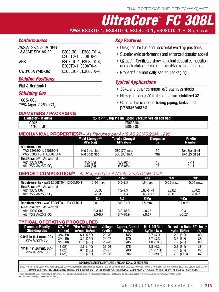
W E L D I N G C O N S U M A B L E S C A T A L O G ı 213
DEPOSIT COMPOSITION(1)
%C(4) %Mn %Si %S %PRequirements - AWS E308LT0-1, E308LT0-4 0.04 max. 0.5-2.5 1.0 max. 0.03 max. 0.04 max.Test Results(3) - As-Welded
with 100% CO2
with 75% Ar/25% CO2
0.030.03
1.2-1.31.2-1.3
0.60-0.700.68-0.77
0.020.01
0.020.02
%Ni %Cr %Mo %Cu Requirements - AWS E308LT0-1, E308LT0-4 9.0-11.0 18.0-21.0 0.5 max. 0.5 max.Test Results(3) - As-Welded
with 100% CO2
with 75% Ar/25% CO2
9.3-9.79.3-9.7
18.2-18.518.7-18.9
0.270.27
0.310.27
(1)Typical all weld metal, DC+. (2)Measured with 0.2% offset. (3)See test results disclaimer on pg. 12. (4)Requirement for E308T0-1 and E308T0-4 is 0.08% max. carbon. (5)To estimate ESO, subtract 1/4 in (6.0 mm) from CTWD. NOTE: Increase Voltage by 2V when using 100% CO2.
TYPICAL OPERATING PROCEDURESDiameter, Polarity
Shielding GasCTWD(5)
mm (in)Wire Feed Speed Voltage
(Volts)Approx. Current
(Amps)Melt-Off Rate Deposition Rate Efficiency
(%)m/min (in/min) kg/hr (lb/hr) kg/hr (lb/hr)
0.045 in (1.1 mm), DC+75% Ar/25% CO2
3/4 (19)3/4 (19)3/4 (19)
6.48.9
11.4
(250)(350)(450)
23-2624-2725-28
145170205
2.73.74.8
(5.9)(8.3)(10.6)
2.33.34.2
(5.2)(7.3)(9.3)
888888
1/16 in (1.6 mm), DC+75% Ar/25% CO2
1 (25)1 (25)1 (25)
3.66.47.6
(140)(250)(300)
23-2624-2725-28
175260285
2.85.19.1
(6.3)(11.1)(20.0)
2.54.47.9
(5.4)(9.7)(17.4)
868787
MECHANICAL PROPERTIES(1)
Yield Strength(2)
MPa (ksi)Tensile Strength
MPa (ksi)Elongation
%Ferrite
NumberRequirements
AWS E308T0-1, E308T0-4AWS E308LT0-1, E308LT0-4
Not SpecifiedNot Specified
520 (75) min.550 (80) min.
35 min.
Not SpecifiedNot Specified
Test Results(3) - As-Weldedwith 100% CO2
with 75% Ar/25% CO2
405 (59)440 (64)
580 (84)605 (88)
4337
7-118-11
IMPORTANT: SPECIAL VENTILATION AND/OR EXHAUST REQUIREDFumes from the normal use of some welding products can contain significant quantities of components - such as chromium and manganese - which can lower the 5.0 mg/m3 maximum exposure guideline for general welding fume.
BEFORE USE, READ AND UNDERSTAND THE MATERIAL SAFETY DATA SHEET (MSDS) FOR THIS PRODUCT AND SPECIFIC INFORMATION PRINTED ON THE PRODUCT CONTAINER.
UltraCore ® FC 308LFLUX-CORED GAS-SHIELDED (FCAW-G) WIRE
Welding PositionsTypical Applications
Flat & Horizontal304L and other common18/8 stainless steels
Nitrogen bearing 304LN and titanium stabilized 321
General fabrication including piping, tanks, and pressure vessels
Designed for flat and horizontal welding positions
Superior weld performance and enhanced operator appeal
Q2 Lot® - Certificate showing actual deposit composition and calculated ferrite number (FN) available online
ProTech® hermetically sealed packaging
Conformances
Shielding Gas100% CO275% Argon / 25% CO2
Key FeaturesAWS A5.22/A5.22M: 1995 & ASME SFA-A5.22:
ABS:
CWB/CSA W48-06:
E308LT0-1, E308LT0-4, E308T0-1, E308T0-4E308LT0-1, E308LT0-4, E308T0-1, E308T0-4E308LT0-1, E308LT0-4
DIAMETERS / PACKAGINGDiameter - in (mm) 25 lb (11.3 kg) Plastic Spool (Vacuum Sealed Foil Bag)
0.0451/16
(1.1)(1.6)
ED033004ED033005
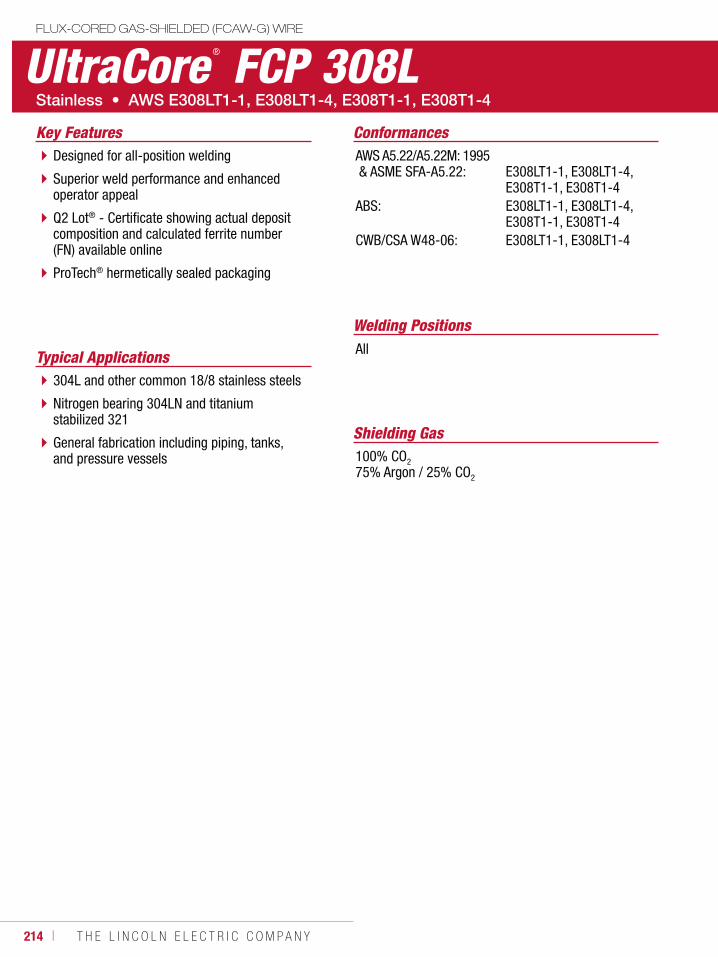
214 ı T H E L I N C O L N E L E C T R I C C O M P A N Y
UltraCore ® FCP 308LFLUX-CORED GAS-SHIELDED (FCAW-G) WIRE
Welding Positions
Typical Applications All
304L and other common 18/8 stainless steels
Nitrogen bearing 304LN and titanium stabilized 321
General fabrication including piping, tanks, and pressure vessels
Designed for all-position welding
Superior weld performance and enhanced operator appeal
Q2 Lot® - Certificate showing actual deposit composition and calculated ferrite number (FN) available online
ProTech® hermetically sealed packaging
Conformances
Shielding Gas100% CO2
75% Argon / 25% CO2
Key FeaturesAWS A5.22/A5.22M: 1995 & ASME SFA-A5.22:
ABS:
CWB/CSA W48-06:
E308LT1-1, E308LT1-4, E308T1-1, E308T1-4E308LT1-1, E308LT1-4, E308T1-1, E308T1-4E308LT1-1, E308LT1-4
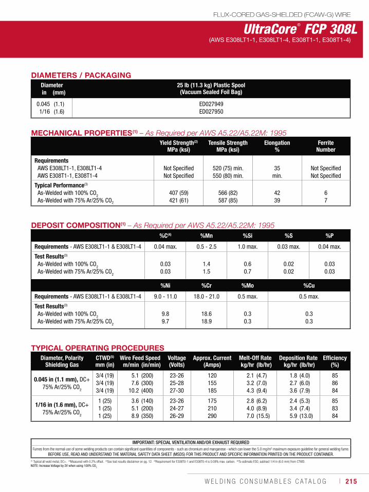
W E L D I N G C O N S U M A B L E S C A T A L O G ı 215
DIAMETERS / PACKAGINGDiameter 25 lb (11.3 kg) Plastic Spool
(Vacuum Sealed Foil Bag)in (mm)
0.0451/16
(1.1)(1.6)
ED027949ED027950
(1) Typical all weld metal, DC+. (2)Measured with 0.2% offset. (3)See test results disclaimer on pg. 12. (4)Requirement for E308T0-1 and E308T0-4 is 0.08% max. carbon. (5)To estimate ESO, subtract 1/4 in (6.0 mm) from CTWD.NOTE: Increase Voltage by 2V when using 100% CO2
UltraCore ® FCP 308LFLUX-CORED GAS-SHIELDED (FCAW-G) WIRE
(AWS E308LT1-1, E308LT1-4, E308T1-1, E308T1-4)
DEPOSIT COMPOSITION(1)
%C(4) %Mn %Si %S %P
Requirements - AWS E308LT1-1 & E308LT1-4 0.04 max. 0.5 - 2.5 1.0 max. 0.03 max. 0.04 max.
Test Results(3)
As-Welded with 100% CO2
As-Welded with 75% Ar/25% CO2
0.030.03
1.41.5
0.60.7
0.020.02
0.030.03
%Ni %Cr %Mo %Cu
Requirements - AWS E308LT1-1 & E308LT1-4 9.0 - 11.0 18.0 - 21.0 0.5 max. 0.5 max.
Test Results(3)
As-Welded with 100% CO2
As-Welded with 75% Ar/25% CO2
9.89.7
18.618.9
0.30.3
0.30.3
TYPICAL OPERATING PROCEDURESDiameter, Polarity
Shielding GasCTWD(5)
mm (in)Wire Feed Speed Voltage
(Volts)Approx. Current
(Amps)Melt-Off Rate Deposition Rate Efficiency
(%)m/min (in/min) kg/hr (lb/hr) kg/hr (lb/hr)
0.045 in (1.1 mm), DC+75% Ar/25% CO
2
3/4 (19)3/4 (19)3/4 (19)
5.17.6
10.2
(200)(300)(400)
23-2625-2827-30
120155185
2.13.24.3
(4.7)(7.0)(9.4)
1.82.73.6
(4.0)(6.0)(7.9)
858684
1/16 in (1.6 mm), DC+75% Ar/25% CO2
1 (25)1 (25)1 (25)
3.65.18.9
(140)(200)(350)
23-2624-2726-29
175210290
2.84.07.0
(6.2)(8.9)(15.5)
2.43.45.9
(5.3)(7.4)(13.0)
858384
MECHANICAL PROPERTIES(1)
Yield Strength(2)
MPa (ksi)Tensile Strength
MPa (ksi)Elongation
%Ferrite
Number
RequirementsAWS E308LT1-1, E308LT1-4 AWS E308T1-1, E308T1-4
Not SpecifiedNot Specified
520 (75) min. 550 (80) min.
35 min.
Not SpecifiedNot Specified
Typical Performance(3)
As-Welded with 100% CO2 As-Welded with 75% Ar/25% CO2
407 (59)421 (61)
566 (82)587 (85)
4239
67
IMPORTANT: SPECIAL VENTILATION AND/OR EXHAUST REQUIREDFumes from the normal use of some welding products can contain significant quantities of components - such as chromium and manganese - which can lower the 5.0 mg/m3 maximum exposure guideline for general welding fume.
BEFORE USE, READ AND UNDERSTAND THE MATERIAL SAFETY DATA SHEET (MSDS) FOR THIS PRODUCT AND SPECIFIC INFORMATION PRINTED ON THE PRODUCT CONTAINER.
216 ı T H E L I N C O L N E L E C T R I C C O M P A N Y
Welding Positions
Typical Applications
Flat & Horizontal
Buffer layers and clad steels – overlays on CMn, mild steel or low alloy steels
Dissimilar joints – stainless types 410, 304L, 321, and 316L to mild and low alloy steels
Designed for flat and horizontal welding positions
For welding dissimilar metals - stainless and mild or low alloy
Superior weld performance and enhanced operator appeal
Q2 Lot® - Certificate showing actual deposit composition and calculated ferrite number (FN) available online
ProTech® hermetically sealed packaging
Conformances
Shielding Gas100% CO2
75% Argon / 25% CO2
Key FeaturesAWS A5.22/A5.22M: 1995 & ASME SFA-A5.22:
ABS:
CWB/CSA W48-06:
E309T0-1, E309T0-4, E309LT0-1, E309LT0-4E309T0-1, E309T0-4, E309LT0-1, E309LT0-4E309LT0-1, E309LT0-4
UltraCore ® FC 309LFLUX-CORED GAS-SHIELDED (FCAW-G) WIRE
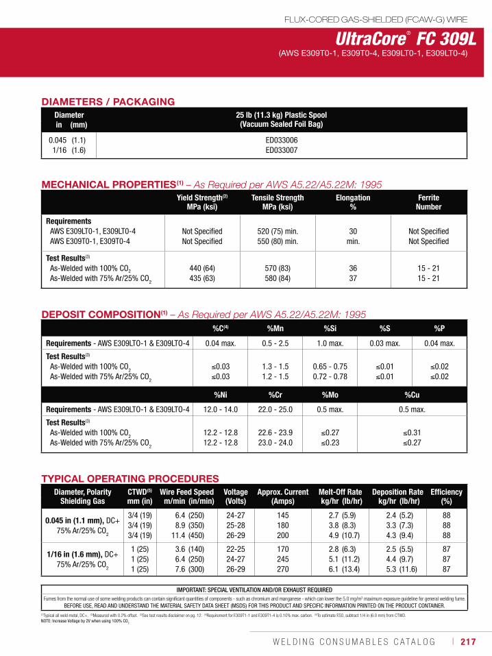
W E L D I N G C O N S U M A B L E S C A T A L O G ı 217
UltraCore ® FC 309LFLUX-CORED GAS-SHIELDED (FCAW-G) WIRE
(AWS E309T0-1, E309T0-4, E309LT0-1, E309LT0-4)
DEPOSIT COMPOSITION(1)
%C(4) %Mn %Si %S %P
Requirements - AWS E309LTO-1 & E309LTO-4 0.04 max. 0.5 - 2.5 1.0 max. 0.03 max. 0.04 max.
Test Results(3)
As-Welded with 100% CO2
As-Welded with 75% Ar/25% CO2
0.030.03
1.3 - 1.51.2 - 1.5
0.65 - 0.750.72 - 0.78
0.010.01
0.020.02
%Ni %Cr %Mo %Cu
Requirements - AWS E309LTO-1 & E309LTO-4 12.0 - 14.0 22.0 - 25.0 0.5 max. 0.5 max.
Test Results(3)
As-Welded with 100% CO2
As-Welded with 75% Ar/25% CO2
12.2 - 12.812.2 - 12.8
22.6 - 23.923.0 - 24.0
0.270.23
0.310.27
TYPICAL OPERATING PROCEDURESDiameter, Polarity
Shielding GasCTWD(5)
mm (in)Wire Feed Speed Voltage
(Volts)Approx. Current
(Amps)Melt-Off Rate Deposition Rate Efficiency
(%)m/min (in/min) kg/hr (lb/hr) kg/hr (lb/hr)
0.045 in (1.1 mm), DC+75% Ar/25% CO2
3/4 (19)3/4 (19)3/4 (19)
6.48.9
11.4
(250)(350)(450)
24-2725-2826-29
145180200
2.73.84.9
(5.9)(8.3)(10.7)
2.43.34.3
(5.2)(7.3)(9.4)
888888
1/16 in (1.6 mm), DC+75% Ar/25% CO2
1 (25)1 (25)1 (25)
3.66.47.6
(140)(250)(300)
22-2524-2726-29
170245270
2.85.16.1
(6.3)(11.2)(13.4)
2.54.45.3
(5.5)(9.7)(11.6)
878787
MECHANICAL PROPERTIES(1)
Yield Strength(2)
MPa (ksi)Tensile Strength
MPa (ksi)Elongation
%Ferrite
Number
RequirementsAWS E309LT0-1, E309LT0-4 AWS E309T0-1, E309T0-4
Not SpecifiedNot Specified
520 (75) min.550 (80) min.
30 min.
Not SpecifiedNot Specified
Test Results(3)
As-Welded with 100% CO2
As-Welded with 75% Ar/25% CO2
440 (64)435 (63)
570 (83)580 (84)
3637
15 - 2115 - 21
DIAMETERS / PACKAGINGDiameter 25 lb (11.3 kg) Plastic Spool
(Vacuum Sealed Foil Bag)in (mm)
0.0451/16
(1.1)(1.6)
ED033006ED033007
IMPORTANT: SPECIAL VENTILATION AND/OR EXHAUST REQUIREDFumes from the normal use of some welding products can contain significant quantities of components - such as chromium and manganese - which can lower the 5.0 mg/m3 maximum exposure guideline for general welding fume.
BEFORE USE, READ AND UNDERSTAND THE MATERIAL SAFETY DATA SHEET (MSDS) FOR THIS PRODUCT AND SPECIFIC INFORMATION PRINTED ON THE PRODUCT CONTAINER.(1)Typical all weld metal, DC+. (2)Measured with 0.2% offset. (3)See test results disclaimer on pg. 12. (4)Requirement for E309T1-1 and E309T1-4 is 0.10% max. carbon. (5)To estimate ESO, subtract 1/4 in (6.0 mm) from CTWD.NOTE: Increase Voltage by 2V when using 100% CO2
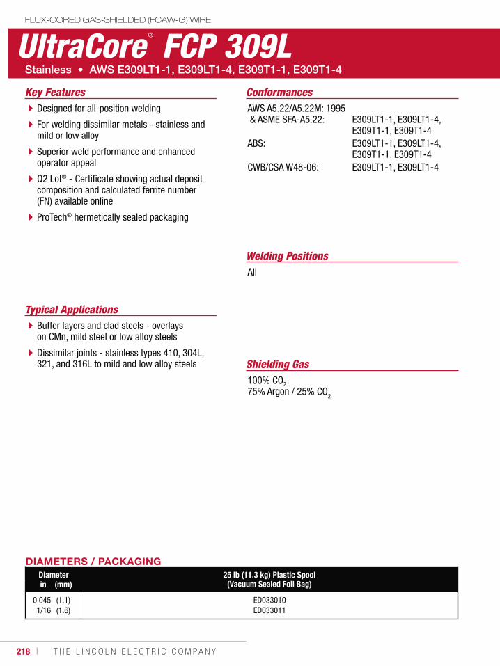
218 ı T H E L I N C O L N E L E C T R I C C O M P A N Y
UltraCore®
FCP 309LFLUX-CORED GAS-SHIELDED (FCAW-G) WIRE
Welding Positions
Typical Applications
All
Buffer layers and clad steels - overlays on CMn, mild steel or low alloy steels
Dissimilar joints - stainless types 410, 304L, 321, and 316L to mild and low alloy steels
Designed for all-position welding
For welding dissimilar metals - stainless and mild or low alloy
Superior weld performance and enhanced operator appeal
Q2 Lot® - Certificate showing actual deposit composition and calculated ferrite number (FN) available online
ProTech® hermetically sealed packaging
ConformancesKey FeaturesAWS A5.22/A5.22M: 1995 & ASME SFA-A5.22:
ABS:
CWB/CSA W48-06:
E309LT1-1, E309LT1-4, E309T1-1, E309T1-4E309LT1-1, E309LT1-4, E309T1-1, E309T1-4E309LT1-1, E309LT1-4
DIAMETERS / PACKAGINGDiameter 25 lb (11.3 kg) Plastic Spool
(Vacuum Sealed Foil Bag)in (mm)
0.0451/16
(1.1)(1.6)
ED033010ED033011
Shielding Gas100% CO2
75% Argon / 25% CO2
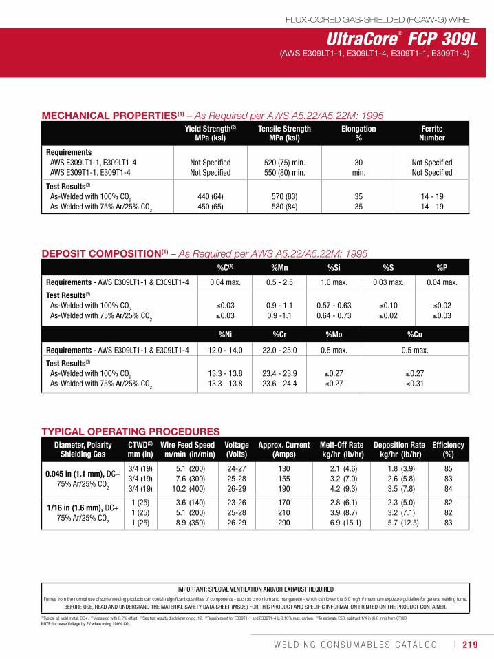
W E L D I N G C O N S U M A B L E S C A T A L O G ı 219
UltraCore ® FCP 309LFLUX-CORED GAS-SHIELDED (FCAW-G) WIRE
(AWS E309LT1-1, E309LT1-4, E309T1-1, E309T1-4)
DEPOSIT COMPOSITION(1)
%C(4) %Mn %Si %S %P
Requirements - AWS E309LT1-1 & E309LT1-4 0.04 max. 0.5 - 2.5 1.0 max. 0.03 max. 0.04 max.
Test Results(3)
As-Welded with 100% CO2
As-Welded with 75% Ar/25% CO2
0.030.03
0.9 - 1.10.9 -1.1
0.57 - 0.630.64 - 0.73
0.100.02
0.020.03
%Ni %Cr %Mo %Cu
Requirements - AWS E309LT1-1 & E309LT1-4 12.0 - 14.0 22.0 - 25.0 0.5 max. 0.5 max.
Test Results(3)
As-Welded with 100% CO2
As-Welded with 75% Ar/25% CO2
13.3 - 13.813.3 - 13.8
23.4 - 23.923.6 - 24.4
0.270.27
0.270.31
(1)Typical all weld metal, DC+. (2)Measured with 0.2% offset. (3)See test results disclaimer on pg. 12. (4)Requirement for E309T1-1 and E309T1-4 is 0.10% max. carbon. (5)To estimate ESO, subtract 1/4 in (6.0 mm) from CTWD.NOTE: Increase Voltage by 2V when using 100% CO2
TYPICAL OPERATING PROCEDURESDiameter, Polarity
Shielding GasCTWD(5)
mm (in)Wire Feed Speed Voltage
(Volts)Approx. Current
(Amps)Melt-Off Rate Deposition Rate Efficiency
(%)m/min (in/min) kg/hr (lb/hr) kg/hr (lb/hr)
0.045 in (1.1 mm), DC+75% Ar/25% CO2
3/4 (19)3/4 (19)3/4 (19)
5.17.6
10.2
(200)(300)(400)
24-2725-2826-29
130155190
2.13.24.2
(4.6)(7.0)(9.3)
1.82.63.5
(3.9)(5.8)(7.8)
858384
1/16 in (1.6 mm), DC+75% Ar/25% CO2
1 (25)1 (25)1 (25)
3.65.18.9
(140)(200)(350)
23-2625-2826-29
170210290
2.83.96.9
(6.1)(8.7)(15.1)
2.33.25.7
(5.0)(7.1)(12.5)
828283
MECHANICAL PROPERTIES(1)
Yield Strength(2)
MPa (ksi)Tensile Strength
MPa (ksi)Elongation
%Ferrite
Number
RequirementsAWS E309LT1-1, E309LT1-4AWS E309T1-1, E309T1-4
Not SpecifiedNot Specified
520 (75) min.550 (80) min.
30min.
Not SpecifiedNot Specified
Test Results(3)
As-Welded with 100% CO2
As-Welded with 75% Ar/25% CO2
440 (64)450 (65)
570 (83)580 (84)
3535
14 - 1914 - 19
IMPORTANT: SPECIAL VENTILATION AND/OR EXHAUST REQUIRED
Fumes from the normal use of some welding products can contain significant quantities of components - such as chromium and manganese - which can lower the 5.0 mg/m3 maximum exposure guideline for general welding fume.
BEFORE USE, READ AND UNDERSTAND THE MATERIAL SAFETY DATA SHEET (MSDS) FOR THIS PRODUCT AND SPECIFIC INFORMATION PRINTED ON THE PRODUCT CONTAINER.
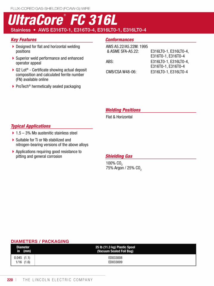
220 ı T H E L I N C O L N E L E C T R I C C O M P A N Y
UltraCore®
FC 316LFLUX-CORED GAS-SHIELDED (FCAW-G) WIRE
Welding Positions
Typical Applications
Flat & Horizontal
1.5 – 3% Mo austenitic stainless steel
Suitable for Ti or Nb stabilized and nitrogen-bearing versions of the above alloys
Applications requiring good resistance to pitting and general corrosion
Designed for flat and horizontal welding positions
Superior weld performance and enhanced operator appeal
Q2 Lot® - Certificate showing actual deposit composition and calculated ferrite number (FN) available online
ProTech® hermetically sealed packaging
Conformances
Shielding Gas100% CO2
75% Argon / 25% CO2
Key FeaturesAWS A5.22/A5.22M: 1995 & ASME SFA-A5.22:
ABS:
CWB/CSA W48-06:
E316LT0-1, E316LT0-4, E316T0-1, E316T0-4E316LT0-1, E316LT0-4, E316T0-1, E316T0-4E316LT0-1, E316LT0-4
DIAMETERS / PACKAGINGDiameter 25 lb (11.3 kg) Plastic Spool
(Vacuum Sealed Foil Bag)in (mm)
0.0451/16
(1.1)(1.6)
ED033008ED033009
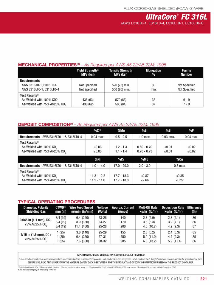
W E L D I N G C O N S U M A B L E S C A T A L O G ı 221
UltraCore ® FC 316LFLUX-CORED GAS-SHIELDED (FCAW-G) WIRE
(AWS E316T0-1, E316T0-4, E316LT0-1, E316LT0-4)
DEPOSIT COMPOSITION(1)
%C(4) %Mn %Si %S %P
Requirements - AWS E316LT0-1 & E316LT0-4 0.04 max. 0.5 - 2.5 1.0 max. 0.03 max. 0.04 max.
Test Results(3)
As-Welded with 100% CO2
As-Welded with 75% Ar/25% CO2
0.030.03
1.2 - 1.31.1 - 1.4
0.60 - 0.700.70 - 0.73
0.010.01
0.020.02
%Ni %Cr %Mo %Cu
Requirements - AWS E316LT0-1 & E316LT0-4 11.0 - 14.0 17.0 - 20.0 2.0 - 3.0 0.5 max.
Test Results(3)
As-Welded with 100% CO2
As-Welded with 75% Ar/25% CO2
11.3 - 12.211.2 - 11.6
17.7 - 18.317.7 - 18.3
2.872.66
0.350.27
(1)Typical all weld metal, DC+. (2)Measured with 0.2% offset. (3)See test results disclaimer on pg. 12. (4)Requirement for E316T1-1 and E316T1-4 is 0.08% max. carbon. (5)To estimate ESO, subtract 1/4 in (6.0 mm) from CTWD.NOTE: Increase Voltage by 2V when using 100% CO2
TYPICAL OPERATING PROCEDURESDiameter, Polarity
Shielding GasCTWD(5)
mm (in)Wire Feed Speed Voltage
(Volts)Approx. Current
(Amps)Melt-Off Rate Deposition Rate Efficiency
(%)m/min (in/min) kg/hr (lb/hr) kg/hr (lb/hr)
0.045 in (1.1 mm), DC+75% Ar/25% CO2
3/4 (19)3/4 (19)3/4 (19)
6.48.9
11.4
(250)(350)(450)
23-2624-2725-28
140170200
2.73.84.8
(5.9)(8.3)(10.7)
2.33.24.2
(5.1)(7.1)(9.3)
868687
1/16 in (1.6 mm), DC+75% Ar/25% CO2
1 (25)1 (25)1 (25)
3.66.47.6
(140)(250)(300)
25-2927-3128-32
155250285
2.85.06.0
(6.2)(11.0)(13.2)
2.44.25.2
(5.3)(9.3)(11.4)
858586
MECHANICAL PROPERTIES(1)
Yield Strength(2)
MPa (ksi)Tensile Strength
MPa (ksi)Elongation
%Ferrite
Number
RequirementsAWS E316T0-1, E316T0-4AWS E316LT0-1, E316LT0-4
Not SpecifiedNot Specified
520 (75) min.550 (80) min.
30min.
Not SpecifiedNot Specified
Test Results(3)
As-Welded with 100% CO2As-Welded with 75% Ar/25% CO2
435 (63)430 (62)
570 (83)580 (84)
3537
6 - 97 - 9
IMPORTANT: SPECIAL VENTILATION AND/OR EXHAUST REQUIRED
Fumes from the normal use of some welding products can contain significant quantities of components - such as chromium and manganese - which can lower the 5.0 mg/m3 maximum exposure guideline for general welding fume.
BEFORE USE, READ AND UNDERSTAND THE MATERIAL SAFETY DATA SHEET (MSDS) FOR THIS PRODUCT AND SPECIFIC INFORMATION PRINTED ON THE PRODUCT CONTAINER.
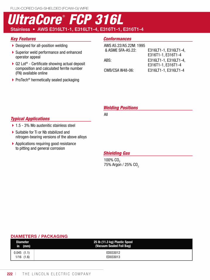
222 ı T H E L I N C O L N E L E C T R I C C O M P A N Y
UltraCore ® FCP 316LFLUX-CORED GAS-SHIELDED (FCAW-G) WIRE
Welding Positions
Typical ApplicationsAll
1.5 - 3% Mo austenitic stainless steel
Suitable for Ti or Nb stabilized and nitrogen-bearing versions of the above alloys
Applications requiring good resistance to pitting and general corrosion
Designed for all-position welding
Superior weld performance and enhanced operator appeal
Q2 Lot® - Certificate showing actual deposit composition and calculated ferrite number (FN) available online
ProTech® hermetically sealed packaging
Conformances
Shielding Gas100% CO2
75% Argon / 25% CO2
Key FeaturesAWS A5.22/A5.22M: 1995 & ASME SFA-A5.22:
ABS:
CWB/CSA W48-06:
E316LT1-1, E316LT1-4, E316T1-1, E316T1-4E316LT1-1, E316LT1-4, E316T1-1, E316T1-4E316LT1-1, E316LT1-4
DIAMETERS / PACKAGINGDiameter 25 lb (11.3 kg) Plastic Spool
(Vacuum Sealed Foil Bag)in (mm)
0.0451/16
(1.1)(1.6)
ED033012ED033013

W E L D I N G C O N S U M A B L E S C A T A L O G ı 223
UltraCore ® FCP 316LFLUX-CORED GAS-SHIELDED (FCAW-G) WIRE
(AWS E316LT1-1, E316LT1-4, E316T1-1, E316T1-4)
DEPOSIT COMPOSITION(1)
%C(4) %Mn %Si %S %P
Requirements - AWS E316LT1-1 & E316LT1-4 0.04 max. 0.5 - 2.5 1.0 max. 0.03 max. 0.04 max.
Test Results(3)
As-Welded with 100% CO2
As-Welded with 75% Ar/25% CO2
0.030.03
1.0 - 1.11.0 - 1.2
0.57 - 0.630.67 - 0.73
0.020.15
0.020.23
%Ni %Cr %Mo %Cu
Requirements - AWS E316LT1-1 & E316LT1-4 11.0 - 14.0 17.0 - 20.0 2.0 - 3.0 0.5 max.
Test Results(3)
As-Welded with 100% CO2
As-Welded with 75% Ar/25% CO2
12.3 - 12.812.3 - 12.8
18.4 - 18.818.9 - 19.4
2.732.81
0.310.31
(1)Typical all weld metal, DC+. (2)Measured with 0.2% offset. (3)See test results disclaimer on pg. 12. (4)Requirement for E316T1-1 and E316T1-4 is 0.08% max. carbon. (5)To estimate ESO, subtract 1/4 in (6.0 mm) from CTWD.NOTE: Increase Voltage by 2V when using 100% CO2
TYPICAL OPERATING PROCEDURESDiameter, Polarity
Shielding GasCTWD(5)
mm (in)Wire Feed Speed Voltage
(Volts)Approx. Current
(Amps)Melt-Off Rate Deposition Rate Efficiency
(%)m/min (in/min) kg/hr (lb/hr) kg/hr (lb/hr)
0.045 in (1.1 mm), DC+75% Ar/25% CO2
3/4 (19)3/4 (19)3/4 (19)
5.17.6
10.2
(200)(300)(400)
22-2523-2624-27
130165190
2.13.24.3
(4.7)(7.1)(9.4)
1.82.73.6
(4.0)(5.9)(7.9)
858384
1/16 in (1.6 mm), DC+75% Ar/25% CO2
1 (25)1 (25)1 (25)
3.65.18.9
(140)(200)(350)
23-2624-2725-28
170205290
2.84.07.0
(6.2)(8.8)(15.3)
2.33.35.6
(5.1)(7.2)(12.4)
828281
MECHANICAL PROPERTIES(1)
Yield Strength(2)
MPa (ksi)Tensile Strength
MPa (ksi)Elongation
%Ferrite
Number
RequirementsAWS E316LT1-1, E316LT1-4AWS E316T1-1, E316T1-4
Not SpecifiedNot Specified
520 (75) min.550 (80) min.
30min.
Not SpecifiedNot Specified
Test Results(3)
As-Welded with 100% CO2
As-Welded with 75% Ar/25% CO2
435 (63)450 (65)
565 (82)585 (85)
3939
7 - 107 - 10
IMPORTANT: SPECIAL VENTILATION AND/OR EXHAUST REQUIRED
Fumes from the normal use of some welding products can contain significant quantities of components - such as chromium and manganese - which can lower the 5.0 mg/m3 maximum exposure guideline for general welding fume.
BEFORE USE, READ AND UNDERSTAND THE MATERIAL SAFETY DATA SHEET (MSDS) FOR THIS PRODUCT AND SPECIFIC INFORMATION PRINTED ON THE PRODUCT CONTAINER.
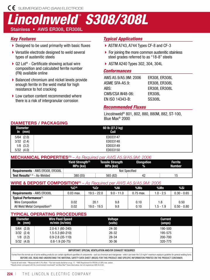
224 ı T H E L I N C O L N E L E C T R I C C O M P A N Y
MECHANICAL PROPERTIES(1)
Yield Strength(2)
MPa (ksi)Tensile Strength
MPa (ksi)Elongation
%Ferrite
NumberRequirements - AWS ER308, ER308L Not SpecifiedTest Results(3, 5) - As-Welded 380 (55) 565 (82) 42 15
WIRE & DEPOSIT COMPOSITION(1)
%C(4) %Cr %Ni %Mo %Mn %SiRequirements - AWS ER308L 0.03 max. 19.5 - 22.0 9.0 - 11.0 0.75 max. 1.0 - 2.5 0.30 - 0.65Typical Performance(3)
Wire CompositionAll Weld Metal Composition(5)
0.020.02
20.119.0 - 19.5
9.89.8
0.100.10
1.81.5 - 1.9
0.500.50 - 0.80
(1)Typical all weld metal. (2)Measured with 0.2% offset. (3)See test results disclaimer on pg. 12. (4)AWS Requirement for ER308 is 0.08% max. carbon. (5)Results shown correspond with the recommended Lincolnweld® and Blue Max® fluxes listed above, but not required per AWS A5.9-93.
TYPICAL OPERATING PROCEDURESDiameter Wire Feed Speed Voltage
(volts)Current(amps)in (mm) m/min (in/min)
5/643/321/8
5/32
(2.0)(2.4)(3.2)(4.0)
2.0-6.1 (80-240)1.5-5.3 (60-210)0.9-2.8 (35-110)0.8-1.9 (30-75)
24-3026-3228-3430-36
190-500195-575200-700320-775
Lincolnweld ® S308/308LSUBMERGED ARC (SAW) ELECTRODE
Typical ApplicationsASTM A743, A744 Types CF-8 and CF-3
For joining the more common austenitic stainlesssteel grades referred to as “18-8” steels
ASTM A240 Types 302, 304, 304L
Designed to be used primarily with basic fluxes
Versatile electrode designed to weld several types of austenitic steels
Q2 Lot® - Certificate showing actual wirecomposition and calculated ferrite number (FN) available online
Balanced chromium and nickel levels provide enough ferrite in the weld metal for high resistance to hot cracking
Low carbon content recommended where there is a risk of intergranular corrosion
Conformances
Recommended FluxesLincolnweld® 801, 802, 880, 880M, 882, ST-100, Blue Max® 2000
Key Features
AWS A5.9/A5.9M: 2006ASME SFA-A5.9:ABS:CWB/CSA W48-06:EN ISO 14343-B:
ER308, ER308LER308, ER308LER308, ER308LER308LSS308L
DIAMETERS / PACKAGINGDiameter 60 lb (27.2 kg)
Coilin (mm)
5/643/321/8
5/32
(2.0)(2.4)(3.2)(4.0)
ED033147ED033148ED033149ED033150
IMPORTANT: SPECIAL VENTILATION AND/OR EXHAUST REQUIRED
Fumes from the normal use of some welding products can contain significant quantities of components - such as chromium and manganese - which can lower the 5.0 mg/m3 maximum exposure guideline for general welding fume.
BEFORE USE, READ AND UNDERSTAND THE MATERIAL SAFETY DATA SHEET (MSDS) FOR THIS PRODUCT AND SPECIFIC INFORMATION PRINTED ON THE PRODUCT CONTAINER.
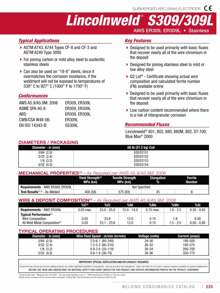
W E L D I N G C O N S U M A B L E S C A T A L O G ı 225
IMPORTANT: SPECIAL VENTILATION AND/OR EXHAUST REQUIRED
Fumes from the normal use of some welding products can contain significant quantities of components - such as chromium and manganese - which can lower the 5.0 mg/m3 maximum exposure guideline for general welding fume.
BEFORE USE, READ AND UNDERSTAND THE MATERIAL SAFETY DATA SHEET (MSDS) FOR THIS PRODUCT AND SPECIFIC INFORMATION PRINTED ON THE PRODUCT CONTAINER.
WIRE & DEPOSIT COMPOSITION(1)
%C(4) %Cr %Ni %Mo %Mn %SiRequirements - AWS ER309L 0.03 max. 23.0 - 25.0 12.0 - 14.0 0.75 max. 1.0 - 2.5 0.30 - 0.65Typical Performance(3)
Wire CompositionAll Weld Metal Composition(5)
0.020.03
23.923.1 - 23.6
13.013.0
0.150.15
1.81.5 - 2.0
0.500.50 - 0.80
(1)Typical all weld metal. (2)Measured with 0.2% offset. (3)See test results disclaimer on pg. 12. (4)AWS Requirement for ER309 is 0.12% max. carbon. (5)Results shown correspond with the recommended Lincolnweld® and Blue Max® fluxes listed above, but not required per AWS A5.9-93.
TYPICAL OPERATING PROCEDURESDiameter - in (mm) Wire Feed Speed - m/min (in/min) Voltage (volts) Current (amps)
5/643/321/8
5/32
(2.0)(2.4)(3.2)(4.0)
2.0-6.11.5-5.30.9-2.80.8-1.9
(80-240)(60-210)(35-110)(30-75)
24-3026-3228-3430-36
190-500195-575200-700320-775
Lincolnweld ® S309/309LSUBMERGED ARC (SAW) ELECTRODE
Typical ApplicationsASTM A743, A744 Types CF-8 and CF-3 and ASTM A240 Type 309S
For joining carbon or mild alloy steel to austenitic stainless steels
Can also be used on “18-8” steels, since it overmatches the corrosion resistance, if the weldment will not be exposed to temperatures of 538° C to 927° C (1000° F to 1700° F)
Designed to be used primarily with basic fluxes that recover nearly all of the wire chromium in the deposit
Designed for joining stainless steel to mild or low alloy steel
Q2 Lot® - Certificate showing actual wirecomposition and calculated ferrite number (FN) available online
Designed to be used primarily with basic fluxes that recover nearly all of the wire chromium in the deposit
Low carbon content recommended where there is a risk of intergranular corrosion
Conformances
Recommended FluxesLincolnweld® 801, 802, 880, 880M, 882, ST-100, Blue Max® 2000
Key Features
AWS A5.9/A5.9M: 2006ASME SFA-A5.9:ABS:CWB/CSA W48-06:EN ISO 14343-B:
ER309, ER309LER309, ER309LER309, ER309LER309LSS309L
DIAMETERS / PACKAGINGDiameter - in (mm) 60 lb (27.2 kg) Coil
5/643/321/8
5/32
(2.0)(2.4)(3.2)(4.0)
ED033151ED033152ED033153ED033154
MECHANICAL PROPERTIES(1)
Yield Strength(2)
MPa (ksi)Tensile Strength
MPa (ksi)Elongation
%Ferrite
NumberRequirements - AWS ER309, ER309L Not SpecifiedTest Results(3, 5) - As-Welded 400 (58) 575 (83) 35 8
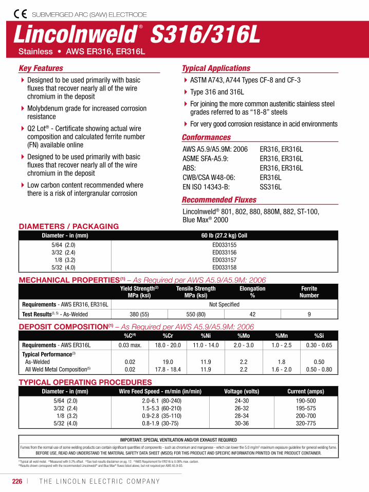
226 ı T H E L I N C O L N E L E C T R I C C O M P A N Y
DEPOSIT COMPOSITION(1)
%C(4) %Cr %Ni %Mo %Mn %Si
Requirements - AWS ER316L 0.03 max. 18.0 - 20.0 11.0 - 14.0 2.0 - 3.0 1.0 - 2.5 0.30 - 0.65
Typical Performance(3)
As-WeldedAll Weld Metal Composition(5)
0.020.02
19.017.8 - 18.4
11.911.9
2.22.2
1.81.6 - 2.0
0.500.50 - 0.80
(1)Typical all weld metal. (2)Measured with 0.2% offset. (3)See test results disclaimer on pg. 12. (4)AWS Requirement for ER316 is 0.08% max. carbon. (5)Results shown correspond with the recommended Lincolnweld® and Blue Max® fluxes listed above, but not required per AWS A5.9-93.
TYPICAL OPERATING PROCEDURESDiameter - in (mm) Wire Feed Speed - m/min (in/min) Voltage (volts) Current (amps)
5/643/321/8
5/32
(2.0)(2.4)(3.2)(4.0)
2.0-6.11.5-5.30.9-2.80.8-1.9
(80-240)(60-210)(35-110)(30-75)
24-3026-3228-3430-36
190-500195-575200-700320-775
Lincolnweld ® S316/316LSUBMERGED ARC (SAW) ELECTRODE
Typical ApplicationsASTM A743, A744 Types CF-8 and CF-3
Type 316 and 316L
For joining the more common austenitic stainless steel grades referred to as “18-8” steels
For very good corrosion resistance in acid environments
Designed to be used primarily with basic fluxes that recover nearly all of the wire chromium in the deposit
Molybdenum grade for increased corrosion resistance
Q2 Lot® - Certificate showing actual wirecomposition and calculated ferrite number (FN) available online
Designed to be used primarily with basic fluxes that recover nearly all of the wire chromium in the deposit
Low carbon content recommended where there is a risk of intergranular corrosion
Conformances
Recommended FluxesLincolnweld® 801, 802, 880, 880M, 882, ST-100, Blue Max® 2000
Key Features
AWS A5.9/A5.9M: 2006ASME SFA-A5.9:ABS:CWB/CSA W48-06:EN ISO 14343-B:
ER316, ER316LER316, ER316LER316, ER316LER316LSS316L
DIAMETERS / PACKAGINGDiameter - in (mm) 60 lb (27.2 kg) Coil
5/643/321/8
5/32
(2.0)(2.4)(3.2)(4.0)
ED033155ED033156ED033157ED033158
MECHANICAL PROPERTIES(1)
Yield Strength(2)
MPa (ksi)Tensile Strength
MPa (ksi)Elongation
%Ferrite
NumberRequirements - AWS ER316, ER316L Not Specified
Test Results(3, 5) - As-Welded 380 (55) 550 (80) 42 9
IMPORTANT: SPECIAL VENTILATION AND/OR EXHAUST REQUIRED
Fumes from the normal use of some welding products can contain significant quantities of components - such as chromium and manganese - which can lower the 5.0 mg/m3 maximum exposure guideline for general welding fume.
BEFORE USE, READ AND UNDERSTAND THE MATERIAL SAFETY DATA SHEET (MSDS) FOR THIS PRODUCT AND SPECIFIC INFORMATION PRINTED ON THE PRODUCT CONTAINER.
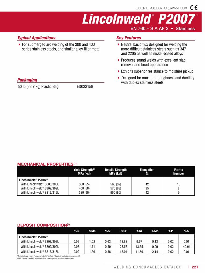
W E L D I N G C O N S U M A B L E S C A T A L O G ı 227
Lincolnweld ® P2007 ™
SUBMERGED ARC (SAW) FLUX
Typical ApplicationsFor submerged arc welding of the 300 and 400 series stainless steels, and similar alloy filler metal
Neutral basic flux designed for welding the more difficult stainless steels such as 347 and 2205 as well as nickel-based alloys
Produces sound welds with excellent slag removal and bead appearance
Exhibits superior resistance to moisture pickup
Designed for maximum toughness and ductility with duplex stainless steels
Key Features
MECHANICAL PROPERTIES(1)
Yield Strength(2)
MPa (ksi)Tensile Strength
MPa (ksi)Elongation
%Ferrite
Number
Lincolnweld® P2007(3)
With Lincolnweld® S308/308L With Lincolnweld® S309/309LWith Lincolnweld® S316/316L
380 (55)400 (58)380 (55)
565 (82)570 (83) 550 (80)
423542
1089
DEPOSIT COMPOSITION(1)
%C %Mn %Si %Cr %Ni %Mo %P %S
Lincolnweld® P2007(3) With Lincolnweld® S308/308L 0.02 1.52 0.63 18.83 9.67 0.13 0.02 0.01
With Lincolnweld® S309/309L 0.03 1.71 0.59 23.58 13.35 0.09 0.02 <0.01
With Lincolnweld® S316/316L 0.02 1.36 0.58 18.04 11.50 2.14 0.02 0.01(1)Typical all weld metal. (2)Measured with 0.2% offset. (3)See test results disclaimer on pg. 12.NOTE: There are no AWS requirements for submerged arc stainless steel deposits.
Packaging50 lb (22.7 kg) Plastic Bag ED033159
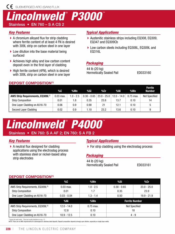
228 ı T H E L I N C O L N E L E C T R I C C O M P A N Y
Lincolnweld ® P3000 ™
SUBMERGED ARC (SAW) FLUX
Typical ApplicationsAustenitic stainless strips including EQ308, EQ309, EQ347 and EQ309Cb
Low carbon steels including EQ308L, EQ309L and EQ316L
A chromium alloyed flux for strip cladding where ferrite content of at least 4 FN is desired with 309L strip on carbon steel in one layer
Low dilution into the base material being surfaced
Achieves high alloy and low carbon content deposit even in the first layer of cladding
High ferrite content (4FN), which is desired with 309L strip on carbon steel in one layer
Key Features
DEPOSIT COMPOSITION(1)
%C %Mn %Si %Cr %Ni %MoFerrite
Number
AWS Strip Requirements, EQ309L(2)
Strip Composition 0.03 max.
0.011.0 - 2.5
1.80.30 - 0.65
0.3523.0 - 25.0
23.812.0 - 14.0
13.70.75 max.
0.10Not Specified
14
One Layer Cladding on A516-70 0.06 0.9 0.90 21 12.1 0.10 5
Second Layer Cladding 0.02 0.9 1.10 23.2 13.6 0.10 9
(1)Typical all weld metal. (2)See test results disclaimer on pg. 12. NOTE: There are no AWS requirements for submerged arc stainless steel deposits. Deposit composition depends strongly upon dilution, especially on single layer welds.
Packaging
Packaging
44 lb (20 kg) Hermetically Sealed Pail
44 lb (20 kg) Hermetically Sealed Pail
ED033160
ED033161
Lincolnweld ® P4000 ™
Typical ApplicationsFor strip cladding using the electroslag processA neutral flux designed for cladding
applications using the electroslag process with stainless steel or nickel-based alloy strip electrodes
Key Features
DEPOSIT COMPOSITION(1)
%C %Mn %Si %Cr
AWS Strip Requirements, EQ309L(2)
Strip Composition 0.03 max.
0.011.0 - 2.5
1.70.30 - 0.65
0.3523.0 - 25.0
23.9
One Layer Cladding on A516-70 0.03 - 0.04 1.3 - 1.4 0.50 19.9 - 21.9
%Ni %Mo Ferrite Number
AWS Strip Requirements, EQ309L(2)
Strip Composition 12.0 - 14.0
12.80.75 max.
0.10Not Specified
18
One Layer Cladding on A516-70 10.9 - 12.5 0.10 4 - 9
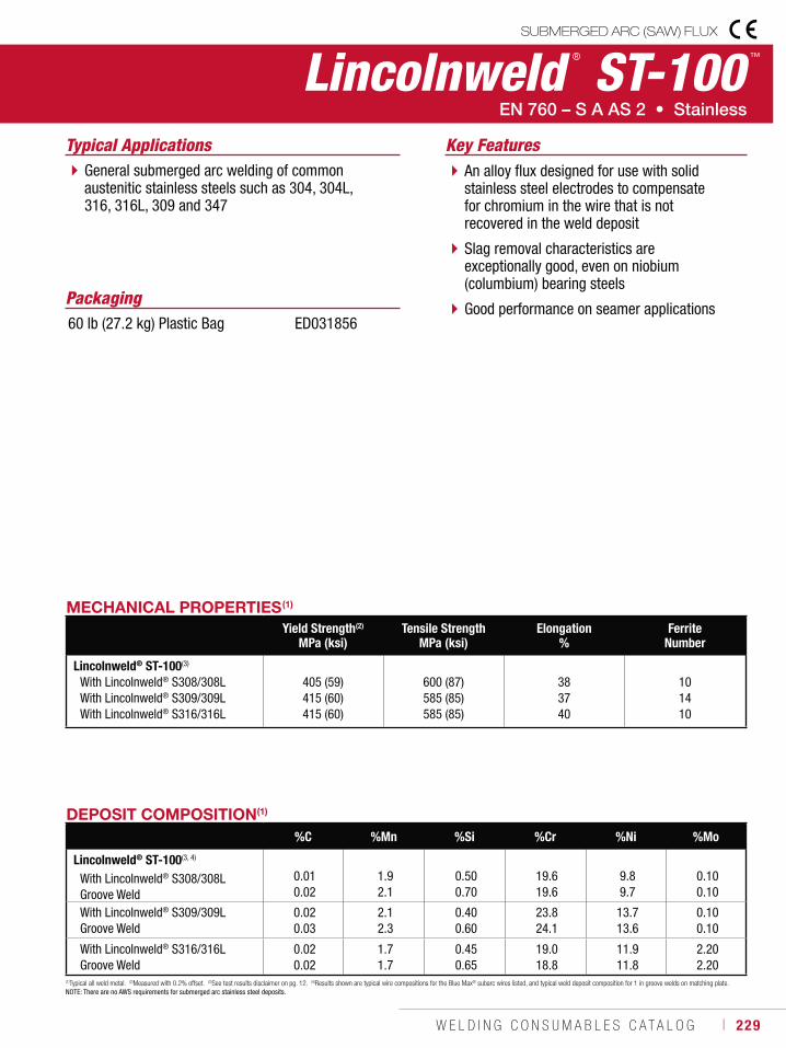
W E L D I N G C O N S U M A B L E S C A T A L O G ı 229
Packaging60 lb (27.2 kg) Plastic Bag ED031856
Lincolnweld ® ST-100 ™
SUBMERGED ARC (SAW) FLUX
Typical ApplicationsGeneral submerged arc welding of common austenitic stainless steels such as 304, 304L, 316, 316L, 309 and 347
An alloy flux designed for use with solid stainless steel electrodes to compensate for chromium in the wire that is not recovered in the weld deposit
Slag removal characteristics are exceptionally good, even on niobium (columbium) bearing steels
Good performance on seamer applications
Key Features
MECHANICAL PROPERTIES(1)
Yield Strength(2)
MPa (ksi)Tensile Strength
MPa (ksi)Elongation
%Ferrite
Number
Lincolnweld® ST-100(3)
With Lincolnweld® S308/308L With Lincolnweld® S309/309LWith Lincolnweld® S316/316L
405 (59)415 (60)415 (60)
600 (87)585 (85)585 (85)
383740
101410
DEPOSIT COMPOSITION(1)
%C %Mn %Si %Cr %Ni %Mo
Lincolnweld® ST-100(3, 4)
With Lincolnweld® S308/308L Groove Weld
0.01 0.02
1.9 2.1
0.50 0.70
19.6 19.6
9.8 9.7
0.10 0.10
With Lincolnweld® S309/309LGroove Weld
0.02 0.03
2.1 2.3
0.40 0.60
23.8 24.1
13.7 13.6
0.10 0.10
With Lincolnweld® S316/316L Groove Weld
0.02 0.02
1.7 1.7
0.45 0.65
19.0 18.8
11.9 11.8
2.20 2.20
(1)Typical all weld metal. (2)Measured with 0.2% offset. (3)See test results disclaimer on pg. 12. (4)Results shown are typical wire compositions for the Blue Max® subarc wires listed, and typical weld deposit composition for 1 in groove welds on matching plate. NOTE: There are no AWS requirements for submerged arc stainless steel deposits.
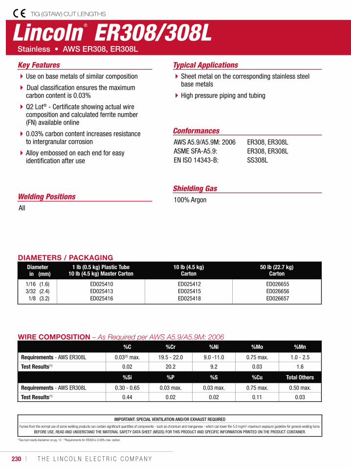
230 ı T H E L I N C O L N E L E C T R I C C O M P A N Y
Lincoln ® ER308/308LTIG (GTAW) CUT LENGTHS
Welding Positions
Typical Applications
All
Sheet metal on the corresponding stainless steel base metals
High pressure piping and tubing
Use on base metals of similar composition
Dual classification ensures the maximum carbon content is 0.03%
Q2 Lot® - Certificate showing actual wirecomposition and calculated ferrite number (FN) available online
0.03% carbon content increases resistance to intergranular corrosion
Alloy embossed on each end for easy identification after use
Conformances
Shielding Gas100% Argon
Key Features
AWS A5.9/A5.9M: 2006ASME SFA-A5.9:EN ISO 14343-B:
ER308, ER308LER308, ER308LSS308L
DIAMETERS / PACKAGINGDiameter 1 lb (0.5 kg) Plastic Tube
10 lb (4.5 kg) Master Carton10 lb (4.5 kg)
Carton50 lb (22.7 kg)
Cartonin (mm)
1/163/321/8
(1.6)(2.4)(3.2)
ED025410 ED025413 ED025416
ED025412 ED025415 ED025418
ED026655 ED026656 ED026657
WIRE COMPOSITION %C %Cr %Ni %Mo %Mn
Requirements - AWS ER308L 0.03(2) max. 19.5 - 22.0 9.0 -11.0 0.75 max. 1.0 - 2.5
Test Results(1) 0.02 20.2 9.2 0.03 1.6
%Si %P %S %Cu Total Others
Requirements - AWS ER308L 0.30 - 0.65 0.03 max. 0.03 max. 0.75 max. 0.50 max.
Test Results(1) 0.44 0.02 0.02 0.11 0.03
(1)See test results disclaimer on pg. 12. (2)Requirements for ER308 is 0.08% max. carbon.
IMPORTANT: SPECIAL VENTILATION AND/OR EXHAUST REQUIRED
Fumes from the normal use of some welding products can contain significant quantities of components - such as chromium and manganese - which can lower the 5.0 mg/m3 maximum exposure guideline for general welding fume.
BEFORE USE, READ AND UNDERSTAND THE MATERIAL SAFETY DATA SHEET (MSDS) FOR THIS PRODUCT AND SPECIFIC INFORMATION PRINTED ON THE PRODUCT CONTAINER.
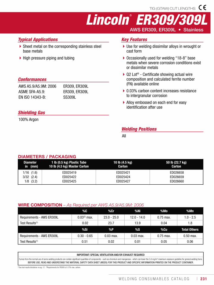
W E L D I N G C O N S U M A B L E S C A T A L O G ı 231
Lincoln ® ER309/309LTIG (GTAW) CUT LENGTHS
Welding Positions
Typical Applications
All
Sheet metal on the corresponding stainless steel base metals
High pressure piping and tubing
Use for welding dissimilar alloys in wrought or cast form
Occasionally used for welding “18-8” base metals when severe corrosion conditions exist or dissimilar metals
Q2 Lot® - Certificate showing actual wirecomposition and calculated ferrite number (FN) available online
0.03% carbon content increases resistance to intergranular corrosion
Alloy embossed on each end for easy identification after use
Conformances
Shielding Gas100% Argon
Key Features
AWS A5.9/A5.9M: 2006ASME SFA-A5.9:EN ISO 14343-B:
ER309, ER309LER309, ER309LSS309L
DIAMETERS / PACKAGINGDiameter 1 lb (0.5 kg) Plastic Tube
10 lb (4.5 kg) Master Carton10 lb (4.5 kg)
Carton50 lb (22.7 kg)
Cartonin (mm)
1/163/321/8
(1.6)(2.4)(3.2)
ED025419 ED025422 ED025425
ED025421 ED025424 ED025427
ED026658 ED026659 ED026660
WIRE COMPOSITION%C %Cr %Ni %Mo %Mn
Requirements - AWS ER309L 0.03(2) max. 23.0 - 25.0 12.0 - 14.0 0.75 max. 1.0 - 2.5
Test Results(1) 0.02 23.7 13.9 0.04 1.8
%Si %P %S %Cu Total Others
Requirements - AWS ER309L 0.30 - 0.65 0.03 max. 0.03 max. 0.75 max. 0.50 max.
Test Results(1) 0.51 0.02 0.01 0.05 0.06
(1)See test results disclaimer on pg. 12. (2)Requirements for ER309 is 0.12% max. carbon.
IMPORTANT: SPECIAL VENTILATION AND/OR EXHAUST REQUIRED
Fumes from the normal use of some welding products can contain significant quantities of components - such as chromium and manganese - which can lower the 5.0 mg/m3 maximum exposure guideline for general welding fume.
BEFORE USE, READ AND UNDERSTAND THE MATERIAL SAFETY DATA SHEET (MSDS) FOR THIS PRODUCT AND SPECIFIC INFORMATION PRINTED ON THE PRODUCT CONTAINER.
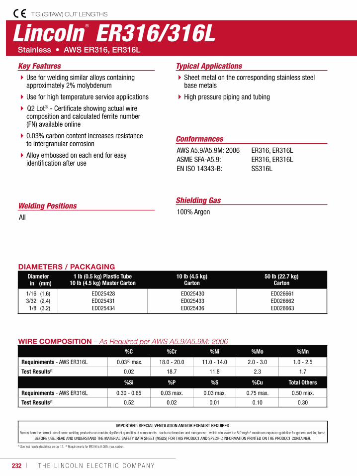
232 ı T H E L I N C O L N E L E C T R I C C O M P A N Y
Lincoln ® ER316/316LTIG (GTAW) CUT LENGTHS
Welding Positions
Typical Applications
All
Sheet metal on the corresponding stainless steel base metals
High pressure piping and tubing
Use for welding similar alloys containing approximately 2% molybdenum
Use for high temperature service applications
Q2 Lot® - Certificate showing actual wirecomposition and calculated ferrite number (FN) available online
0.03% carbon content increases resistance to intergranular corrosion
Alloy embossed on each end for easy identification after use
Conformances
Shielding Gas100% Argon
Key Features
AWS A5.9/A5.9M: 2006ASME SFA-A5.9:EN ISO 14343-B:
ER316, ER316LER316, ER316LSS316L
DIAMETERS / PACKAGINGDiameter 1 lb (0.5 kg) Plastic Tube
10 lb (4.5 kg) Master Carton10 lb (4.5 kg)
Carton50 lb (22.7 kg)
Cartonin (mm)
1/163/321/8
(1.6)(2.4)(3.2)
ED025428 ED025431 ED025434
ED025430 ED025433 ED025436
ED026661 ED026662 ED026663
WIRE COMPOSITION %C %Cr %Ni %Mo %Mn
Requirements - AWS ER316L 0.03(2) max. 18.0 - 20.0 11.0 - 14.0 2.0 - 3.0 1.0 - 2.5
Test Results(1) 0.02 18.7 11.8 2.3 1.7
%Si %P %S %Cu Total Others
Requirements - AWS ER316L 0.30 - 0.65 0.03 max. 0.03 max. 0.75 max. 0.50 max.
Test Results(1) 0.52 0.02 0.01 0.10 0.30
(1) See test results disclaimer on pg. 12. (2) Requirements for ER316 is 0.08% max. carbon.
IMPORTANT: SPECIAL VENTILATION AND/OR EXHAUST REQUIRED
Fumes from the normal use of some welding products can contain significant quantities of components - such as chromium and manganese - which can lower the 5.0 mg/m3 maximum exposure guideline for general welding fume.
BEFORE USE, READ AND UNDERSTAND THE MATERIAL SAFETY DATA SHEET (MSDS) FOR THIS PRODUCT AND SPECIFIC INFORMATION PRINTED ON THE PRODUCT CONTAINER.
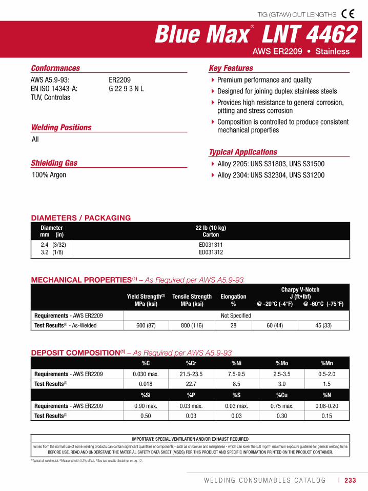
W E L D I N G C O N S U M A B L E S C A T A L O G ı 233
(1)Typical all weld metal. (2)Measured with 0.2% offset. (3)See test results disclaimer on pg. 12.
Blue Max ® LNT 4462TIG (GTAW) CUT LENGTHS
DIAMETERS / PACKAGINGDiameter 22 lb (10 kg)
Cartonmm (in)
2.43.2
(3/32)(1/8)
ED031311ED031312
MECHANICAL PROPERTIES(1)
Yield Strength(2)
Tensile Strength
ElongationCharpy V-Notch
J (ft•lbf)MPa (ksi) MPa (ksi) % @ -20°C (-4°F) @ -60°C (-75°F)
Requirements - AWS ER2209 Not Specified
Test Results(2) - As-Welded 600 (87) 800 (116) 28 60 (44) 45 (33)
IMPORTANT: SPECIAL VENTILATION AND/OR EXHAUST REQUIRED
Fumes from the normal use of some welding products can contain significant quantities of components - such as chromium and manganese - which can lower the 5.0 mg/m3 maximum exposure guideline for general welding fume.
BEFORE USE, READ AND UNDERSTAND THE MATERIAL SAFETY DATA SHEET (MSDS) FOR THIS PRODUCT AND SPECIFIC INFORMATION PRINTED ON THE PRODUCT CONTAINER.
Welding Positions
Typical Applications
All
Alloy 2205: UNS S31803, UNS S31500
Alloy 2304: UNS S32304, UNS S31200
Premium performance and quality
Designed for joining duplex stainless steels
Provides high resistance to general corrosion, pitting and stress corrosion
Composition is controlled to produce consistent mechanical properties
Conformances
Shielding Gas100% Argon
Key FeaturesAWS A5.9-93:EN ISO 14343-A: TUV, Controlas
ER2209G 22 9 3 N L
DEPOSIT COMPOSITION(1)
%C %Cr %Ni %Mo %Mn
Requirements - AWS ER2209 0.030 max. 21.5-23.5 7.5-9.5 2.5-3.5 0.5-2.0
Test Results(3) 0.018 22.7 8.5 3.0 1.5
%Si %P %S %Cu %N
Requirements - AWS ER2209 0.90 max. 0.03 max. 0.03 max. 0.75 max. 0.08-0.20
Test Results(3) 0.50 0.03 0.03 0.30 0.15
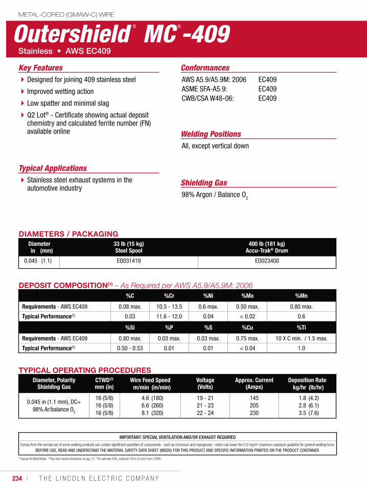
234 ı T H E L I N C O L N E L E C T R I C C O M P A N Y
Outershield ® MC ®-409METAL-CORED (GMAW-C) WIRE
Welding Positions
Typical Applications
All, except vertical down
Stainless steel exhaust systems in the automotive industry
Designed for joining 409 stainless steel
Improved wetting action
Low spatter and minimal slag
Q2 Lot® - Certificate showing actual depositchemistry and calculated ferrite number (FN) available online
Conformances
Shielding Gas98% Argon / Balance O2
Key FeaturesAWS A5.9/A5.9M: 2006ASME SFA-A5.9:CWB/CSA W48-06:
EC409EC409EC409
DIAMETERS / PACKAGINGDiameter 33 lb (15 kg)
Steel Spool400 lb (181 kg)
Accu-Trak® Drumin (mm)
0.045 (1.1) ED031419 ED023400
DEPOSIT COMPOSITION(1)
%C %Cr %Ni %Mo %Mn
Requirements - AWS EC409 0.08 max. 10.5 - 13.5 0.6 max. 0.50 max. 0.80 max.
Typical Performance(2) 0.03 11.6 - 12.0 0.04 < 0.02 0.6
%Si %P %S %Cu %Ti
Requirements - AWS EC409 0.80 max. 0.03 max. 0.03 max. 0.75 max. 10 X C min. / 1.5 max.
Typical Performance(2) 0.50 - 0.53 0.01 0.01 < 0.04 1.0
(1)Typical All Weld Metal. (2)See test results disclaimer on pg. 12. (3)To estimate ESO, subtract 1/8 in (3 mm) from CTWD.
TYPICAL OPERATING PROCEDURESDiameter, Polarity
Shielding GasCTWD(3)
mm (in)Wire Feed Speed Voltage
(Volts)Approx. Current
(Amps)Deposition Rate
m/min (in/min) kg/hr (lb/hr)
0.045 in (1.1 mm), DC+98% Ar/balance O2
16 (5/8)16 (5/8)16 (5/8)
4.66.68.1
(180)(260)(320)
19 - 2121 - 2322 - 24
145205230
1.82.83.5
(4.2)(6.1)(7.6)
IMPORTANT: SPECIAL VENTILATION AND/OR EXHAUST REQUIRED
Fumes from the normal use of some welding products can contain significant quantities of components - such as chromium and manganese - which can lower the 5.0 mg/m3 maximum exposure guideline for general welding fume.
BEFORE USE, READ AND UNDERSTAND THE MATERIAL SAFETY DATA SHEET (MSDS) FOR THIS PRODUCT AND SPECIFIC INFORMATION PRINTED ON THE PRODUCT CONTAINER.
W E L D I N G C O N S U M A B L E S C A T A L O G ı 235
Stick ElectrodeBuild-UpWearshield® BU ..................................... 236
Metal-to-Metal WearWearshield® MI ..................................... 237Wearshield® Mangjet® ........................... 238
Severe ImpactWearshield® 15CrMn ............................. 239Wearshield® FROG MANG® .................... 240
Abrasion Plus ImpactWearshield® ABR ................................... 241Wearshield® 44 ..................................... 242
Metal-to-Earth WearWearshield® ME .................................... 243
Severe AbrasionWearshield® 60 ..................................... 244
Maintenance and RepairBlue Max® 2100 .................................... 245
Flux-Cored (FCAW-G) WireBuild-UpLincore® BU-G ....................................... 246
Metal-to-MetalLincore® 55-G ....................................... 247
Metal-Cored WireBuild-UpLincore® 60-G ....................................... 248
Flux-Cored (FCAW-G) WireBuild-UpLincore® BU........................................... 249Lincore® 33 ........................................... 250
Metal-to-MetalLincore® 40-O ....................................... 251Lincore® 55 ........................................... 252Lincore® T & D ...................................... 253
Severe ImpactLincore® M ............................................ 254Lincore® 15CrMn ................................... 255Lincore® FROG MANG® .......................... 256
Flux-Cored (FCAW-G) WireAbrasion Plus ImpactLincore® 50 ........................................... 257
Severe AbrasionLincore® 60-O ....................................... 258Lincore® 65-O ....................................... 259
Metal-Cored Submerged Arc WireBuild-UpLincore® 30-S ....................................... 260
Metal-to-Metal, Build UpLincore® 32-S ....................................... 261Lincore® 35-S ....................................... 262
Metal-to-MetalLincore® 40-S ....................................... 263Lincore® 42-S ....................................... 264
Roll Rebuilding, Build UpLincore® 20 ........................................... 265Lincore® 8620 ....................................... 266Lincore® 4130 ....................................... 267
Roll Rebuilding, Metal-to-MetalLincore® 410 ......................................... 268Lincore® 410NiMo ................................. 269Lincore® 423L ....................................... 270Lincore® 423Cr ..................................... 271Lincore® 420 ......................................... 272Lincore® 96-S ....................................... 273Lincore® 102W ...................................... 274Lincore® 102HC .................................... 275
Submerged Arc FluxHardfacingLincolnweld® A-96-S ............................. 276Lincolnweld® H-535™ ............................ 276Lincolnweld® H-560™ ............................ 277
Neutral FluxLincolnweld® 801® ................................ 277Lincolnweld® 802® ................................ 278Lincolnweld® 803™ ............................... 278
CONSUMABLES
HARDFACING
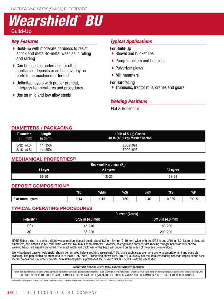
236 ı T H E L I N C O L N E L E C T R I C C O M P A N Y
Wearshield ® BUHARDFACING STICK (SMAW) ELECTRODE
Welding Positions
Typical Applications
Flat & Horizontal
For Build-UpShovel and bucket lips
Pump impellers and housings
Pulverizer plows
Mill hammers
For HardfacingTrunnions, tractor rolls, cranes and gears
Build-up with moderate hardness to resist shock and metal-to-metal wear, as in rolling and sliding
Can be used as underbase for other hardfacing deposits or as final overlay on parts to be machined or forged
Unlimited layers with proper preheat, interpass temperatures and procedures
Use on mild and low alloy steels
Key Features
DIAMETERS / PACKAGINGDiameter Length 10 lb (4.5 kg) Carton
40 lb (18.1 kg) Master Cartonin (mm) in (mm)
5/323/16
(4.0)(4.8)
14 (350)14 (350)
ED021991ED021993
MECHANICAL PROPERTIES(1)
Rockwell Hardness (RC)1 Layer 2 Layers 3 Layers
15-20 18-23 23-28
TYPICAL OPERATING PROCEDURESCurrent (Amps)
Polarity(2) 5/32 in (4.0 mm) 3/16 in (4.8 mm)
DC+ 145-210 180-280
AC 155-225 200-290
NOTE: Using a short arc with a slight weave motion, deposit beads about 1/2 in - 3/4 in (13-19 mm) wide with the 5/32 in and 3/16 in (4.0-4.8 mm) electrode diameters, and about 1 in (25 mm) wide with the 1/4 in (6.4 mm) diameter. However, on edges and corners, fast-moving stringer beads or very narrow weaved beads are usually preferred. The exact width and thickness of the bead will depend on the mass of the piece being welded.
Work-hardened base or weld metal should be removed before applying Wearshield® BU, since such areas are more prone to embrittlement and possible cracking. The part should be preheated to at least 21°C (70°F). Preheating above 40°C (100°F) is usually not required. Preheating depends largely on the base metal composition. On large, complex, or restrained parts, a preheat of 150°- 260°C (300°- 500°F) may be necessary.
DEPOSIT COMPOSITION(1)
%C %Mn %Si %Cr %S %P
2 or more layers 0.14 1.15 0.60 1.40 0.025 0.015
(1)Composition and properties depend upon dilution. Single layer deposit properties depend upon base metal and/or build-up material. (2)Preferred polarity is listed first.
IMPORTANT: SPECIAL VENTILATION AND/OR EXHAUST REQUIREDFumes from the normal use of some welding products can contain significant quantities of components - such as chromium and manganese - which can lower the 5.0 mg/m3 maximum exposure guideline for general welding fume.
BEFORE USE, READ AND UNDERSTAND THE MATERIAL SAFETY DATA SHEET (MSDS) FOR THIS PRODUCT AND SPECIFIC INFORMATION PRINTED ON THE PRODUCT CONTAINER.
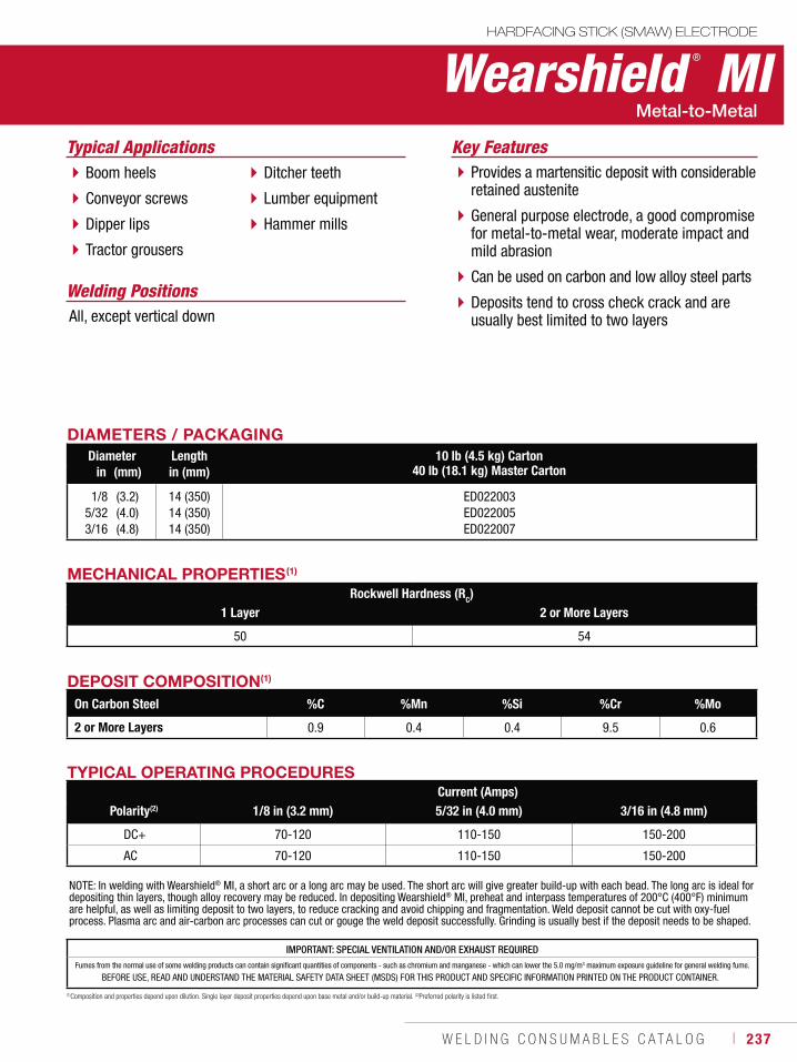
W E L D I N G C O N S U M A B L E S C A T A L O G ı 237
IMPORTANT: SPECIAL VENTILATION AND/OR EXHAUST REQUIREDFumes from the normal use of some welding products can contain significant quantities of components - such as chromium and manganese - which can lower the 5.0 mg/m3 maximum exposure guideline for general welding fume.
BEFORE USE, READ AND UNDERSTAND THE MATERIAL SAFETY DATA SHEET (MSDS) FOR THIS PRODUCT AND SPECIFIC INFORMATION PRINTED ON THE PRODUCT CONTAINER.
Wearshield ® MIHARDFACING STICK (SMAW) ELECTRODE
Welding Positions
Typical Applications
All, except vertical down
Boom heels
Conveyor screws
Dipper lips
Tractor grousers
Ditcher teeth
Lumber equipment
Hammer mills
Provides a martensitic deposit with considerable retained austenite
General purpose electrode, a good compromise for metal-to-metal wear, moderate impact and mild abrasion
Can be used on carbon and low alloy steel parts
Deposits tend to cross check crack and are usually best limited to two layers
Key Features
DIAMETERS / PACKAGINGDiameter Length 10 lb (4.5 kg) Carton
40 lb (18.1 kg) Master Cartonin (mm) in (mm)
1/85/323/16
(3.2)(4.0)(4.8)
14 (350)14 (350)14 (350)
ED022003ED022005ED022007
MECHANICAL PROPERTIES(1)
Rockwell Hardness (RC)1 Layer 2 or More Layers
50 54
TYPICAL OPERATING PROCEDURESCurrent (Amps)
Polarity(2) 1/8 in (3.2 mm) 5/32 in (4.0 mm) 3/16 in (4.8 mm)
DC+ 70-120 110-150 150-200
AC 70-120 110-150 150-200
NOTE: In welding with Wearshield® MI, a short arc or a long arc may be used. The short arc will give greater build-up with each bead. The long arc is ideal for depositing thin layers, though alloy recovery may be reduced. In depositing Wearshield® MI, preheat and interpass temperatures of 200°C (400°F) minimum are helpful, as well as limiting deposit to two layers, to reduce cracking and avoid chipping and fragmentation. Weld deposit cannot be cut with oxy-fuel process. Plasma arc and air-carbon arc processes can cut or gouge the weld deposit successfully. Grinding is usually best if the deposit needs to be shaped.
DEPOSIT COMPOSITION(1)
On Carbon Steel %C %Mn %Si %Cr %Mo
2 or More Layers 0.9 0.4 0.4 9.5 0.6
(1)Composition and properties depend upon dilution. Single layer deposit properties depend upon base metal and/or build-up material. (2)Preferred polarity is listed first.
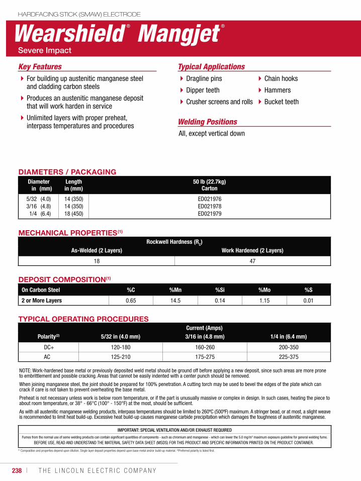
238 ı T H E L I N C O L N E L E C T R I C C O M P A N Y
Wearshield ® Mangjet ®
HARDFACING STICK (SMAW) ELECTRODE
Welding Positions
Typical Applications
All, except vertical down
Dragline pins
Dipper teeth
Crusher screens and rolls
Chain hooks
Hammers
Bucket teeth
For building up austenitic manganese steel and cladding carbon steels
Produces an austenitic manganese deposit that will work harden in service
Unlimited layers with proper preheat, interpass temperatures and procedures
Key Features
DIAMETERS / PACKAGINGDiameter Length 50 lb (22.7kg)
Cartonin (mm) in (mm)
5/323/161/4
(4.0)(4.8)(6.4)
14 (350)14 (350)18 (450)
ED021976ED021978ED021979
MECHANICAL PROPERTIES(1)
Rockwell Hardness (RC)As-Welded (2 Layers) Work Hardened (2 Layers)
18 47
TYPICAL OPERATING PROCEDURESCurrent (Amps)
Polarity(2) 5/32 in (4.0 mm) 3/16 in (4.8 mm) 1/4 in (6.4 mm)
DC+ 120-180 160-260 200-350
AC 125-210 175-275 225-375
NOTE: Work-hardened base metal or previously deposited weld metal should be ground off before applying a new deposit, since such areas are more prone to embrittlement and possible cracking. Areas that cannot be easily indented with a center punch should be removed.
When joining manganese steel, the joint should be prepared for 100% penetration. A cutting torch may be used to bevel the edges of the plate which can crack if care is not taken to prevent overheating the base metal.
Preheat is not necessary unless work is below room temperature, or if the part is unusually massive or complex in design. In such cases, heating the piece to about room temperature, or 38° - 66°C (100° - 150°F) at the most, should be sufficient.
As with all austenitic manganese welding products, interpass temperatures should be limited to 260ºC (500ºF) maximum. A stringer bead, or at most, a slight weave is recommended to limit heat build-up. Excessive heat build-up causes manganese carbide precipitation which damages the toughness of austenitic manganese.
DEPOSIT COMPOSITION(1)
On Carbon Steel %C %Mn %Si %Mo %S
2 or More Layers 0.65 14.5 0.14 1.15 0.01
(1) Composition and properties depend upon dilution. Single layer deposit properties depend upon base metal and/or build-up material. (2)Preferred polarity is listed first.
IMPORTANT: SPECIAL VENTILATION AND/OR EXHAUST REQUIREDFumes from the normal use of some welding products can contain significant quantities of components - such as chromium and manganese - which can lower the 5.0 mg/m3 maximum exposure guideline for general welding fume.
BEFORE USE, READ AND UNDERSTAND THE MATERIAL SAFETY DATA SHEET (MSDS) FOR THIS PRODUCT AND SPECIFIC INFORMATION PRINTED ON THE PRODUCT CONTAINER.
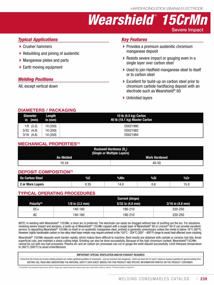
W E L D I N G C O N S U M A B L E S C A T A L O G ı 239
IMPORTANT: SPECIAL VENTILATION AND/OR EXHAUST REQUIREDFumes from the normal use of some welding products can contain significant quantities of components - such as chromium and manganese - which can lower the 5.0 mg/m3 maximum exposure guideline for general welding fume.
BEFORE USE, READ AND UNDERSTAND THE MATERIAL SAFETY DATA SHEET (MSDS) FOR THIS PRODUCT AND SPECIFIC INFORMATION PRINTED ON THE PRODUCT CONTAINER.
Wearshield ® 15CrMnHARDFACING STICK (SMAW) ELECTRODE
Welding Positions
Typical Applications
All, except vertical down
Crusher hammers
Rebuilding and joining of austenitic
Manganese plates and parts
Earth moving equipment
Provides a premium austenitic chromium manganese deposit
Resists severe impact or gouging even in a single layer over carbon steel
Used to join Hadfield manganese steel to itself or to carbon steel
Excellent for build-up on carbon steel prior to chromium carbide hardfacing deposit with an electrode such as Wearshield® 60
Unlimited layers
Key Features
DIAMETERS / PACKAGINGDiameter Length 10 lb (4.5 kg) Carton
40 lb (18.1 kg) Master Cartonin (mm) in (mm)
1/85/323/16
(3.2)(4.0)(4.8)
14 (350)14 (350)14 (350)
ED021980ED021982ED021984
MECHANICAL PROPERTIES(1)
Rockwell Hardness (RC)(Single or Multiple Layers)
As-Welded Work Hardened
18-24 40-50
TYPICAL OPERATING PROCEDURESCurrent (Amps)
Polarity(2) 1/8 in (3.2 mm) 5/32 in (4.0 mm) 3/16 in (4.8 mm)
DC+ 140-160 190-210 220-250
AC 140-160 190-210 220-250
NOTE: In welding with Wearshield® 15CrMn, a short arc is preferred. The electrode can easily be dragged without fear of snuffing out the arc. For situationsinvolving severe impact and abrasion, a build-up of Wearshield® 15CrMn capped with a single layer of Wearshield® 60 or Lincore® 60-O can provide excellent service. In depositing Wearshield® 15CrMn on itself or on austenitic manganese steel, preheat is generally unnecessary unless the metal is below 16°C (60°F). However, highly hardenable carbon or low alloy steel base metals may require preheat in the 150°C - 204°C (300° - 400°F) range to avoid heat affected zone cracking.
Wearshield® 15CrMn deposits work harden rapidly, which makes them difficult to machine. Best results are obtained with carbide or ceramic tool bits. Avoid superficial cuts, and maintain a sharp cutting edge. Grinding can also be done successfully. Because of the high chromium content, Wearshield®15CrMn cannot be cut with oxy-fuel processes. Plasma arc and air carbon arc processes can cut or gouge the weld deposit successfully. Limit interpass temperature to 260°C (500°F) to avoid embrittlement.
DEPOSIT COMPOSITION(1)
On Carbon Steel %C %Mn %Si %Cr
2 or More Layers 0.35 14.0 0.6 15.0
(1) Composition and properties depend upon dilution. Single layer deposit properties depend upon base metal and/or build-up material. (2)Preferred polarity is listed first.
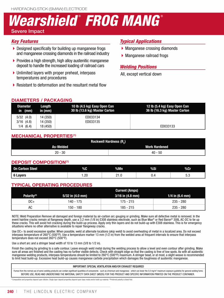
240 ı T H E L I N C O L N E L E C T R I C C O M P A N Y
Welding PositionsAll, except vertical down
Wearshield ® FROG MANG ®
HARDFACING STICK (SMAW) ELECTRODE
Typical ApplicationsManganese crossing diamonds
Manganese railroad frogs
Designed specifically for building up manganese frogs and manganese crossing diamonds in the railroad industry
Provides a high strength, high alloy austenitic manganese deposit to handle the increased loading of railroad cars
Unlimited layers with proper preheat, interpass temperatures and procedures
Resistant to deformation and the resultant metal flow
Key Features
MECHANICAL PROPERTIES(1)
Rockwell Hardness (RC)As-Welded Work Hardened
20 - 30 40 - 50
DIAMETERS / PACKAGINGDiameter Length 10 lb (4.5 kg) Easy Open Can
30 lb (13.6 kg) Master Carton12 lb (5.4 kg) Easy Open Can 36 lb (16.3 kg) Master Cartonin (mm) in (mm)
5/323/161/4
(4.0)(4.8)(6.4)
14 (350)14 (350)18 (450)
ED033134ED033135
ED033133
DEPOSIT COMPOSITION(1)
On Carbon Steel %C %Mn %Si %Cr
6 Layers 1.20 21.0 0.4 5.3
(1)Composition and properties depend upon dilution. Single layer deposit properties depend upon base metal and/or build-up material. (2)Preferred polarity is listed first.
TYPICAL OPERATING PROCEDURESCurrent (Amps)
Polarity(2) 5/32 in (4.0 mm) 3/16 in (4.8 mm) 1/4 in (6.4 mm)
DC+ 140 - 175 175 - 215 235 - 280
AC 150 - 180 185 - 215 235 - 280
NOTE: Weld Preparation Remove all damaged and foreign material by air-carbon arc gouging or grinding. Make sure all defective metal is removed. In the event hairline cracks remain at flangeway depth, use a 3.2 mm (1/8 in) E308 stainless electrode, such as Blue Max® or Red Baron® 308L AC-DC to tie up these cracks. This will avoid hot cracking during the build-up process. Apply only thin layers and do not build-up with E308 stainless. This is for emergency situations where no other alternative is available to repair flangeway cracks.
Use DC+ to avoid excessive spatter. When possible, weld at alternate locations (skip weld) to avoid overheating of metal in a localized area. Do not exceed interpass temperature of 260°C (500°F). Use a temperature marker 13 mm (1/2 in) from the welded area at frequent intervals to ensure that interpass temperature does not exceed 260°C (500°F).
Use a short arc and a stringer bead width of 10 to 13 mm (3/8 to 1/2 in).
Finish the casting by grinding to a safe contour. Leave enough weld metal during the welding process to allow a level and even contour after grinding. Make sure all areas are finished and the casting has no further visible defects. Check with straight edge so that the casting is free of low spots. As with all austenitic manganese welding products, interpass temperatures should be limited to 260°C (500°F) maximum. A stringer bead, or at most, a slight weave is recommended to limit heat build-up. Excessive heat build-up causes manganese carbide precipitation which damages the toughness of austenitic manganese.
IMPORTANT: SPECIAL VENTILATION AND/OR EXHAUST REQUIREDFumes from the normal use of some welding products can contain significant quantities of components - such as chromium and manganese - which can lower the 5.0 mg/m3 maximum exposure guideline for general welding fume.
BEFORE USE, READ AND UNDERSTAND THE MATERIAL SAFETY DATA SHEET (MSDS) FOR THIS PRODUCT AND SPECIFIC INFORMATION PRINTED ON THE PRODUCT CONTAINER.

W E L D I N G C O N S U M A B L E S C A T A L O G ı 241
IMPORTANT: SPECIAL VENTILATION AND/OR EXHAUST REQUIREDFumes from the normal use of some welding products can contain significant quantities of components - such as chromium and manganese - which can lower the 5.0 mg/m3 maximum exposure guideline for general welding fume.
BEFORE USE, READ AND UNDERSTAND THE MATERIAL SAFETY DATA SHEET (MSDS) FOR THIS PRODUCT AND SPECIFIC INFORMATION PRINTED ON THE PRODUCT CONTAINER.
Wearshield ® ABRHARDFACING STICK (SMAW) ELECTRODE
Welding Positions
Typical Applications
All
Crusher hammers
Dozer blades
Dipper teeth and lips
Coal mining cutters
Truck chain and gears
Provides good resistance to abrasion, impact and some metal-to-metal wear
Good hot forging properties
Use on carbon, stainless and manganese steels
Deposits limited to two layers
Can be forged readily without affecting its mechanical properties
Key Features
DIAMETERS / PACKAGINGDiameter Length 10 lb (4.5 kg) Carton
40 lb (18.1 kg) Cartonin (mm) in (mm)
1/85/323/16
(3.2)(4.0)(4.8)
14 (350)14 (350)14 (350)
ED021996ED021998ED022000
MECHANICAL PROPERTIES(1)
Rockwell Hardness (RC)1 Layer 2 Layers
24-53 28-53
DEPOSIT COMPOSITION(1)
On Carbon Steel %C %Mn %Si %Cr %Mo
2 Layers 2.1 1.1 0.75 6.5 0.40
(1)Composition and properties depend upon dilution. Single layer deposit properties depend upon base metal and/or build-up material. (2)Preferred polarity is listed first.
TYPICAL OPERATING PROCEDURESCurrent (Amps)
Polarity(2) 1/8 in (3.2 mm) 5/32 in (4.0 mm) 3/16 in (4.8 mm)
DC+ 40-150 75-200 110-250
AC 50-165 80-220 120-275
NOTE: Wearshield® ABR can be forged readily without affecting its mechanical properties. As deposited, Wearshield® ABR weld metal is not machinable, although the deposit can be shaped by grinding.
To obtain a deposit that is machinable with carbide tools, heat to about 749ºC (1380ºF) and hold for one hour per inch of thickness.
Air cool to room temperature.
For maximum machinability, heat to 870° - 900°C (1600° - 1650°F) and hold for one hour per inch of thickness. Furnace cool to 650°C (1200°F) at a rate not exceeding 10°C (50°F) per hour, and air or furnace cool to room temperature. Variation in welding procedures will have little affect on abrasion resistance.
The abrasion resistance can be restored by heating to about 790°C (1450°F), quenching and tempering at 200°C (400°F).
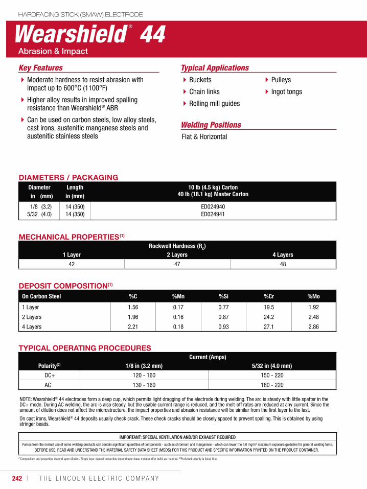
242 ı T H E L I N C O L N E L E C T R I C C O M P A N Y
Wearshield ® 44HARDFACING STICK (SMAW) ELECTRODE
Welding Positions
Typical Applications
Flat & Horizontal
Buckets
Chain links
Rolling mill guides
Pulleys
Ingot tongs
Moderate hardness to resist abrasion with impact up to 600°C (1100°F)
Higher alloy results in improved spalling resistance than Wearshield® ABR
Can be used on carbon steels, low alloy steels, cast irons, austenitic manganese steels and austenitic stainless steels
Key Features
DIAMETERS / PACKAGINGDiameter Length 10 lb (4.5 kg) Carton
40 lb (18.1 kg) Master Cartonin (mm) in (mm)
1/85/32
(3.2)(4.0)
14 (350)14 (350)
ED024940ED024941
DEPOSIT COMPOSITION(1)
On Carbon Steel %C %Mn %Si %Cr %Mo
1 Layer 1.56 0.17 0.77 19.5 1.92
2 Layers 1.96 0.16 0.87 24.2 2.48
4 Layers 2.21 0.18 0.93 27.1 2.86
MECHANICAL PROPERTIES(1)
Rockwell Hardness (RC)1 Layer 2 Layers 4 Layers
42 47 48
(1)Composition and properties depend upon dilution. Single layer deposit properties depend upon base metal and/or build-up material. (2)Preferred polarity is listed first.
TYPICAL OPERATING PROCEDURESCurrent (Amps)
Polarity(2) 1/8 in (3.2 mm) 5/32 in (4.0 mm)
DC+ 120 - 160 150 - 220
AC 130 - 160 180 - 220
NOTE: Wearshield® 44 electrodes form a deep cup, which permits light dragging of the electrode during welding. The arc is steady with little spatter in the DC+ mode. During AC welding, the arc is also steady, but the usable current range is reduced, and the melt-off rates are reduced at any current. Since the amount of dilution does not affect the microstructure, the impact properties and abrasion resistance will be similar from the first layer to the last.
On cast irons, Wearshield® 44 deposits usually check crack. These check cracks should be closely spaced to prevent spalling. This is obtained by using stringer beads.
IMPORTANT: SPECIAL VENTILATION AND/OR EXHAUST REQUIREDFumes from the normal use of some welding products can contain significant quantities of components - such as chromium and manganese - which can lower the 5.0 mg/m3 maximum exposure guideline for general welding fume.
BEFORE USE, READ AND UNDERSTAND THE MATERIAL SAFETY DATA SHEET (MSDS) FOR THIS PRODUCT AND SPECIFIC INFORMATION PRINTED ON THE PRODUCT CONTAINER.
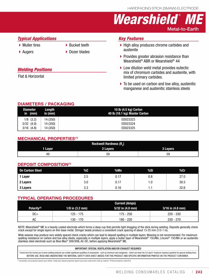
W E L D I N G C O N S U M A B L E S C A T A L O G ı 243
IMPORTANT: SPECIAL VENTILATION AND/OR EXHAUST REQUIREDFumes from the normal use of some welding products can contain significant quantities of components - such as chromium and manganese - which can lower the 5.0 mg/m3 maximum exposure guideline for general welding fume.
BEFORE USE, READ AND UNDERSTAND THE MATERIAL SAFETY DATA SHEET (MSDS) FOR THIS PRODUCT AND SPECIFIC INFORMATION PRINTED ON THE PRODUCT CONTAINER.
Wearshield ® MEHARDFACING STICK (SMAW) ELECTRODE
Welding Positions
Typical Applications
Flat & Horizontal
Muller tires
Augers
Bucket teeth
Dozer blades
High alloy produces chrome carbides and austenite
Provides greater abrasion resistance than Wearshield® ABR or Wearshield® 44
Low dilution weld metal provides eutectic mix of chromium carbides and austenite, with limited primary carbides.
To be used on carbon and low alloy, austenitic manganese and austenitic stainless steels
Key Features
DIAMETERS / PACKAGINGDiameter Length 10 lb (4.5 kg) Carton
40 lb (18.1 kg) Master Cartonin (mm) in (mm)
1/85/323/16
(3.2)(4.0)(4.8)
14 (350)14 (350)14 (350)
ED023323ED023324ED023325
DEPOSIT COMPOSITION(1)
On Carbon Steel %C %Mn %Si %Cr
1 Layer 2.5 0.17 0.8 27.0
2 Layers 3.0 0.17 1.0 30.5
3 Layers 3.3 0.16 1.1 32.6
MECHANICAL PROPERTIES(1)
Rockwell Hardness (RC)1 Layer 2 Layers 3 Layers
49 59 59
(1) Composition and properties depend upon dilution. Single layer deposit properties depend upon base metal and/or build-up material. (2)Preferred polarity is listed first.
TYPICAL OPERATING PROCEDURESCurrent (Amps)
Polarity(2) 1/8 in (3.2 mm) 5/32 in (4.0 mm) 3/16 in (4.8 mm)
DC+ 125 - 175 175 - 250 220 - 330
AC 130 - 170 180 - 220 230 - 270
NOTE: Wearshield® ME is a heavily coated electrode which forms a deep cup that permits light dragging of the stick during welding. Deposits generally check crack except for single layers on thin base metal. Stringer beads produce a consistent crack spacing of about 13-25 mm (1/2-1 in).
Wide weaves may produce very widely spaced check cracks which can lead to deposit spalling in multiple layers. Weaving is not recommended. For maximum spalling resistance on carbon and low alloy steels, especially in multiple layers, apply a butter layer of Wearshield® 15CrMn, Lincore® 15CrMn or an austenitic stainless steel electrode such as Blue Max® 309/309L AC-DC, before applying Wearshield® ME.
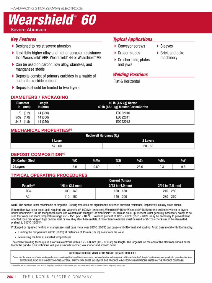
244 ı T H E L I N C O L N E L E C T R I C C O M P A N Y
Wearshield ® 60HARDFACING STICK (SMAW) ELECTRODE
Welding Positions
Typical Applications
Flat & Horizontal
Conveyor screws
Grader blades
Crusher rolls, plates and jaws
Sleeves
Brick and coke machinery
Designed to resist severe abrasion
It exhibits higher alloy and higher abrasion resistance than Wearshield® ABR, Wearshield® 44 or Wearshield® ME
Can be used on carbon, low alloy, stainless, and manganese steels
Deposits consist of primary carbides in a matrix of austenite-carbide eutectic
Deposits should be limited to two layers
Key Features
DIAMETERS / PACKAGINGDiameter Length 10 lb (4.5 kg) Carton
40 lb (18.1 kg) Master CartonCartonin (mm) in (mm)
1/85/323/16
(3.2)(4.0)(4.8)
14 (350)14 (350)14 (350)
ED022010ED022011ED022012
MECHANICAL PROPERTIES(1)
Rockwell Hardness (RC)1 Layer 2 Layers
57 - 60 60 - 62
DEPOSIT COMPOSITION(1)
On Carbon Steel %C %Mn %Si %Cr %Mo %V
2 Layers 5.0 0.80 1.0 23.0 2.3 0.6
(1)Composition and properties depend upon dilution. Single layer deposit properties depend upon base metal and/or build-up material. (2)Preferred polarity is listed first.
TYPICAL OPERATING PROCEDURESCurrent (Amps)
Polarity(2) 1/8 in (3.2 mm) 5/32 in (4.0 mm) 3/16 in (4.8 mm)
DC+ 100 - 140 130 - 180 210 - 250
AC 110 - 150 140 - 200 230 - 270
NOTE: The deposit is not machinable or forgeable. Cooling rate does not significantly influence abrasion resistance. Deposit will usually cross check.
If more than two-layer build-up is required, use Wearshield® 15CrMn (preferred), Wearshield® BU or Wearshield® BU30 for the preliminary layer or layers under Wearshield® 60. On manganese steel, use Wearshield® Mangjet® or Wearshield® 15CrMn as build-up. Preheat is not generally necessary except to be sure that work is in room temperature range 25° - 45ºC (75° - 100ºF). However, preheat of 120° - 200ºC (250° - 400ºF) may be necessary to prevent heat affected zone cracking on high carbon steel or low alloy steel base metals. If more than two layers must be used, or if cross checks must be eliminated, preheat to 650ºC (1200ºF).
Prolonged or repeated heating of manganese steel base metal over 260ºC (500ºF) can cause embrittlement and spalling. Avoid base metal embrittlement by:
Limiting the temperature 260ºC (500ºF) at distances of 13 mm (1/2 in) away from the weld.
Minimizing the time at elevated temperatures.
The correct welding technique is a vertical electrode with a 3.2 - 4.8 mm (1/8 - 3/16 in) arc length. The large ball on the end of the electrode should never touch the puddle. This technique will give a smooth transfer, low spatter and smooth bead.
IMPORTANT: SPECIAL VENTILATION AND/OR EXHAUST REQUIREDFumes from the normal use of some welding products can contain significant quantities of components - such as chromium and manganese - which can lower the 5.0 mg/m3 maximum exposure guideline for general welding fume.
BEFORE USE, READ AND UNDERSTAND THE MATERIAL SAFETY DATA SHEET (MSDS) FOR THIS PRODUCT AND SPECIFIC INFORMATION PRINTED ON THE PRODUCT CONTAINER.
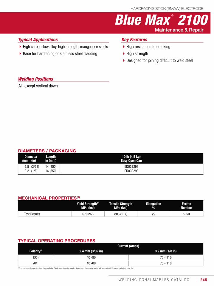
W E L D I N G C O N S U M A B L E S C A T A L O G ı 245
Blue Max ® 2100HARDFACING STICK (SMAW) ELECTRODE
Welding Positions
Typical Applications
All, except vertical down
High carbon, low alloy, high strength, manganese steels
Base for hardfacing or stainless steel cladding
High resistance to cracking
High strength
Designed for joining difficult to weld steel
Key Features
DIAMETERS / PACKAGINGDiameter Length 10 lb (4.5 kg)
Easy Open Canmm (in) in (mm)
2.53.2
(3/32)(1/8)
14 (350)14 (350)
ED032298ED032299
TYPICAL OPERATING PROCEDURESCurrent (Amps)
Polarity(2) 2.4 mm (3/32 in) 3.2 mm (1/8 in)
DC+ 40 -80 75 - 110
AC 40 -80 75 - 110(1)Composition and properties depend upon dilution. Single layer deposit properties depend upon base metal and/or build-up material. (2)Preferred polarity is listed first.
MECHANICAL PROPERTIES(1)
Yield Strength(2)
MPa (ksi)Tensile Strength
MPa (ksi)Elongation
%Ferrite
Number
Test Results 670 (97) 805 (117) 22 > 50
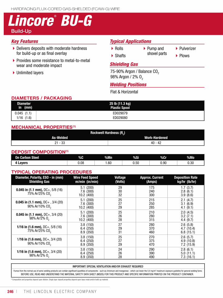
246 ı T H E L I N C O L N E L E C T R I C C O M P A N Y
Lincore ® BU-GHARDFACING FLUX-CORED GAS-SHIELDED (FCAW-G) WIRE
Welding Positions
Typical Applications
Flat & Horizontal
Rolls
Shafts
Pump and shovel parts
Pulverizer
Plows
Delivers deposits with moderate hardness for build-up or as final overlay
Provides some resistance to metal-to-metal wear and moderate impact
Unlimited layers
Key Features
DIAMETERS / PACKAGINGDiameter 25 lb (11.3 kg)
Plastic Spoolin (mm)
0.0451/16
(1.1)(1.6)
ED029079ED029080
Shielding Gas75-90% Argon / Balance CO2
98% Argon / 2% O2
MECHANICAL PROPERTIES(1)
Rockwell Hardness (RC)As-Welded Work-Hardened
21 - 33 40 - 42
DEPOSIT COMPOSITION(1)
On Carbon Steel %C %Mn %Si %Cr %Mo4 Layers 0.08 1.60 0.50 0.90 0.30
(1)Composition and properties depend upon dilution. Single layer deposit properties depend upon base metal and/or build-up material.
TYPICAL OPERATING PROCEDURESDiameter, Polarity, ESO - in (mm)
Shielding GasWire Feed Speed Voltage
(Volts)Approx. Current
(Amps)Deposition Rate
m/min (in/min) kg/hr (lb/hr)
0.045 in (1.1 mm), DC+, 5/8 (16) 75% Ar/25% CO2
5.17.6
10.2
(200)(300)(400)
293032
175240300
1.72.83.9
(3.7)(6.1)(8.6)
0.045 in (1.1 mm), DC+ , 3/4 (20) 90% Ar/10% CO2
5.17.6
10.2
(200)(300)(400)
252729
215250285
2.13.14.1
(4.7)(6.9)(9.1)
0.045 in (1.1 mm), DC+, 3/4 (20) 98% Ar/2% O2
5.17.6
10.2
(200)(300)(400)
252628
210280315
2.03.24.4
(4.5)(7.1)(9.7)
1/16 in (1.6 mm), DC+, 5/8 (16) 75% Ar/25% CO2
3.86.48.9
(150)(250)(350)
272931
280370460
2.64.76.8
(5.8)(10.4)(15.1)
1/16 in (1.6 mm), DC+, 3/4 (20) 90% Ar/10% CO2
3.86.48.9
(150)(250)(350)
252729
270375470
2.64.97.2
(5.7)(10.8)(15.9)
1/16 in (1.6 mm), DC+, 3/4 (20) 98% Ar/2% O2
3.86.48.9
(150)(250)(350)
242628
290390490
2.85.07.3
(6.1)(11.1)(16.1)
IMPORTANT: SPECIAL VENTILATION AND/OR EXHAUST REQUIREDFumes from the normal use of some welding products can contain significant quantities of components - such as chromium and manganese - which can lower the 5.0 mg/m3 maximum exposure guideline for general welding fume.
BEFORE USE, READ AND UNDERSTAND THE MATERIAL SAFETY DATA SHEET (MSDS) FOR THIS PRODUCT AND SPECIFIC INFORMATION PRINTED ON THE PRODUCT CONTAINER.
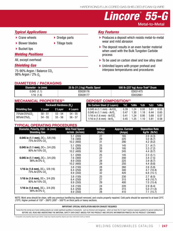
W E L D I N G C O N S U M A B L E S C A T A L O G ı 247
DIAMETERS / PACKAGINGDiameter - in (mm) 25 lb (11.3 kg) Plastic Spool 500 lb (227 kg) Accu-Trak® Drum
0.0451/16
(1.1)(1.6)
ED028176ED028177
ED031475ED032661
Lincore ® 55-GHARDFACING FLUX-CORED GAS-SHIELDED (FCAW-G) WIRE
Typical Applications
All, except overhead
Crane wheels
Blower blades
Bucket lips
Dredge parts
Tillage tools
Produces a deposit which resists metal-to-metal wear and mild abrasion
The deposit results in an even harder material when used with the Bulk Tungsten Carbide process
To be used on carbon steel and low alloy steel
Unlimited layers with proper preheat and interpass temperatures and procedures
Key Features
MECHANICAL PROPERTIES(1)
Rockwell Hardness (RC)Shielding Gas 1 Layer 2 Layer 4 Layers
75%Ar/25%CO2
98%Ar/2%O2
50 - 5154 - 55
53 - 5455 - 56
54 - 5556 - 57
75-90% Argon / Balance CO298% Argon / 2% O2
DEPOSIT COMPOSITION(1)
On Carbon Steel (2 Layers) %C %Mn %Si %Cr %Mo0.045 in (1.1 mm) - Ar/CO20.045 in (1.1 mm) - Ar/O21/16 in (1.6 mm) - Ar/CO21/16 in (1.6 mm) - Ar/O2
0.390.470.410.45
1.241.301.241.25
0.931.180.951.10
5.616.445.695.81
0.550.650.570.58
(1) Composition and properties depend upon dilution. Single layer deposit properties depend upon base metal and/or build-up material.
IMPORTANT: SPECIAL VENTILATION AND/OR EXHAUST REQUIREDFumes from the normal use of some welding products can contain significant quantities of components - such as chromium and manganese - which can lower the 5.0 mg/m3 maximum exposure guideline for general welding fume.
BEFORE USE, READ AND UNDERSTAND THE MATERIAL SAFETY DATA SHEET (MSDS) FOR THIS PRODUCT AND SPECIFIC INFORMATION PRINTED ON THE PRODUCT CONTAINER.
TYPICAL OPERATING PROCEDURESDiameter, Polarity, ESO - in (mm)
Shielding GasWire Feed Speed Voltage
(Volts)Approx. Current
(Amps)Deposition Rate
m/min (in/min) kg/hr (lb/hr)
0.045 in (1.1 mm), DC+, 5/8 (16) 75% Ar/25% CO2
5.17.6
10.2
(200)(300)(400)
272931
165225290
2.03.04.2
(4.3)(6.7)(9.2)
0.045 in (1.1 mm), DC+, 3/4 (20) 90% Ar/10% CO2
5.17.6
10.2
(200)(300)(400)
252830
145195245
2.13.34.4
(4.7)(7.2)(9.7)
0.045 in (1.1 mm), DC+, 3/4 (20) 98% Ar/2% O2
5.17.68.9
10.2
(200)(300)(350)(400)
25272829
145200225250
2.33.43.94.4
(5.1)(7.5)(8.7)(9.8)
1/16 in (1.6 mm), DC+, 5/8 (16) 75% Ar/25% CO2
3.86.48.9
(150)(250)(350)
283032
260340420
2.64.76.8
(5.8)(10.4)(15.1)
1/16 in (1.6 mm), DC+, 3/4 (20) 90% Ar/10% CO2
3.86.48.9
(150)(250)(350)
252729
230315400
2.74.97.0
(6.0)(10.7)(15.4)
1/16 in (1.6 mm), DC+, 3/4 (20) 98% Ar/2% O2
3.86.48.9
(150)(250)(350)
242628
220315410
2.95.07.1
(6.4)(11.0)(15.7)
NOTE: Work area should be clean, with any previous hardfacing deposit removed, and cracks properly repaired. Cold parts should be warmed to at least 25ºC (75ºF). Higher preheat of 150° - 260ºC (300° - 500°F) on thick parts or heavy sections.
Welding Positions
Shielding Gas
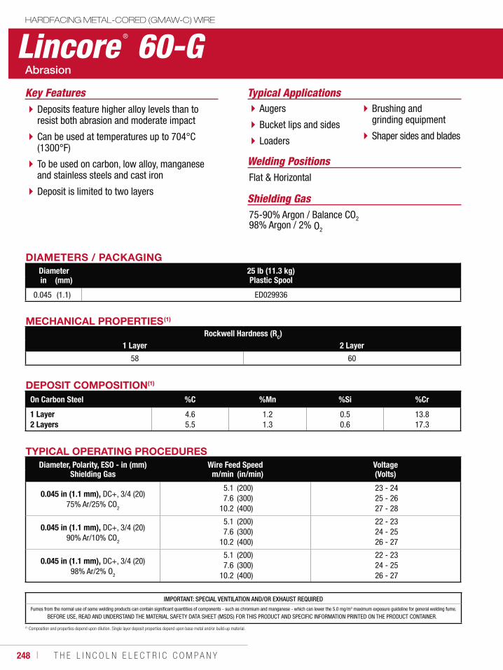
248 ı T H E L I N C O L N E L E C T R I C C O M P A N Y
IMPORTANT: SPECIAL VENTILATION AND/OR EXHAUST REQUIREDFumes from the normal use of some welding products can contain significant quantities of components - such as chromium and manganese - which can lower the 5.0 mg/m3 maximum exposure guideline for general welding fume.
BEFORE USE, READ AND UNDERSTAND THE MATERIAL SAFETY DATA SHEET (MSDS) FOR THIS PRODUCT AND SPECIFIC INFORMATION PRINTED ON THE PRODUCT CONTAINER.
Lincore ® 60-GHARDFACING METAL-CORED (GMAW-C) WIRE
Welding Positions
Typical Applications
Flat & Horizontal
Augers
Bucket lips and sides
Loaders
Brushing and grinding equipment
Shaper sides and blades
Deposits feature higher alloy levels than to resist both abrasion and moderate impact
Can be used at temperatures up to 704°C (1300°F)
To be used on carbon, low alloy, manganese and stainless steels and cast iron
Deposit is limited to two layers
Key Features
DIAMETERS / PACKAGINGDiameter 25 lb (11.3 kg)
Plastic Spoolin (mm)
0.045 (1.1) ED029936
Shielding Gas75-90% Argon / Balance CO298% Argon / 2% O2
DEPOSIT COMPOSITION(1)
On Carbon Steel %C %Mn %Si %Cr
1 Layer2 Layers
4.65.5
1.21.3
0.50.6
13.817.3
(1) Composition and properties depend upon dilution. Single layer deposit properties depend upon base metal and/or build-up material.
MECHANICAL PROPERTIES(1)
Rockwell Hardness (RC)1 Layer 2 Layer
58 60
TYPICAL OPERATING PROCEDURESDiameter, Polarity, ESO - in (mm)
Shielding GasWire Feed Speed Voltage
(Volts)m/min (in/min)
0.045 in (1.1 mm), DC+, 3/4 (20) 75% Ar/25% CO
2
5.17.6
10.2
(200)(300)(400)
23 - 24 25 - 26 27 - 28
0.045 in (1.1 mm), DC+, 3/4 (20) 90% Ar/10% CO2
5.17.6
10.2
(200)(300)(400)
22 - 23 24 - 25 26 - 27
0.045 in (1.1 mm), DC+, 3/4 (20) 98% Ar/2% O2
5.17.6
10.2
(200)(300)(400)
22 - 23 24 - 25 26 - 27
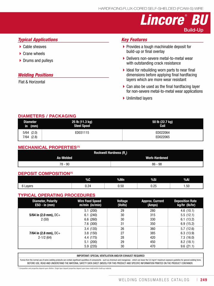
W E L D I N G C O N S U M A B L E S C A T A L O G ı 249
TYPICAL OPERATING PROCEDURESDiameter, Polarity
ESO - in (mm)Wire Feed Speed Voltage
(Volts)Approx. Current
(Amps)Deposition Rate
m/min (in/min) kg/hr (lb/hr)
5/64 in (2.0 mm), DC+ 2 (50)
5.16.16.67.6
(200)(240)(260)(300)
29303031
280315330350
4.65.56.16.9
(10.1)(12.1)(13.2)(15.2)
7/64 in (2.8 mm), DC+ 2-1/2 (64)
3.43.84.45.15.9
(135)(150)(175)(200)(235)
2627282930
360385420450470
5.76.37.38.29.6
(12.6)(13.9)(16.0)(18.1)(21.1)
Lincore ® BUHARDFACING FLUX-CORED SELF-SHIELDED (FCAW-S) WIRE
Welding Positions
Typical Applications
Flat & Horizontal
Cable sheaves
Crane wheels
Drums and pulleys
Provides a tough machinable deposit for build-up or final overlay
Delivers non-severe metal-to-metal wear with outstanding crack resistance
Ideal for rebuilding worn parts to near final dimensions before applying final hardfacing layers which are more wear resistant
Can also be used as the final hardfacing layer for non-severe metal-to-metal wear applications
Unlimited layers
Key Features
DIAMETERS / PACKAGINGDiameter 25 lb (11.3 kg)
Steel Spool50 lb (22.7 kg)
Coilin (mm)
5/647/64
(2.0)(2.8)
ED031115 ED022064ED022065
DEPOSIT COMPOSITION(1)
%C %Mn %Si %Al
6 Layers 0.24 0.50 0.25 1.50
(1) Composition and properties depend upon dilution. Single layer deposit properties depend upon base metal and/or build-up material.
MECHANICAL PROPERTIES(1)
Rockwell Hardness (RC)As-Welded Work-Hardened
78 - 90 86 - 98
IMPORTANT: SPECIAL VENTILATION AND/OR EXHAUST REQUIREDFumes from the normal use of some welding products can contain significant quantities of components - such as chromium and manganese - which can lower the 5.0 mg/m3 maximum exposure guideline for general welding fume.
BEFORE USE, READ AND UNDERSTAND THE MATERIAL SAFETY DATA SHEET (MSDS) FOR THIS PRODUCT AND SPECIFIC INFORMATION PRINTED ON THE PRODUCT CONTAINER.
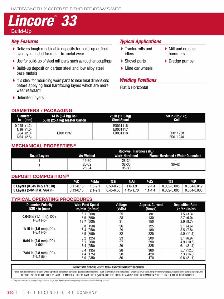
250 ı T H E L I N C O L N E L E C T R I C C O M P A N Y
Lincore ® 33HARDFACING FLUX-CORED SELF-SHIELDED (FCAW-S) WIRE
Welding Positions
Typical Applications
Flat & Horizontal
Tractor rolls and idlers
Shovel parts
Mine car wheels
Mill and crusher hammers
Dredge pumps
Delivers tough machinable deposits for build-up or final overlay intended for metal-to-metal wear
Use for build-up of steel mill parts such as rougher couplings
Build-up deposit on carbon steel and low alloy steel base metals
It is ideal for rebuilding worn parts to near final dimensions before applying final hardfacing layers which are more wear resistant
Unlimited layers
Key Features
DIAMETERS / PACKAGINGDiameter 14 lb (6.4 kg) Coil
56 lb (25.4 kg) Master Carton25 lb (11.3 kg)
Steel Spool50 lb (22.7 kg)
Coilin (mm)
0.0451/16 5/647/64
(1.2)(1.6)(2.0)(2.8)
ED011237
ED031116ED031117ED031118 ED011238
ED011240
MECHANICAL PROPERTIES(1)
Rockwell Hardness (RC)No. of Layers As-Welded Work-Hardened Flame-Hardened / Water Quenched
123
14-3026-3225-34
28-3432-3635-38
–38-42
–
IMPORTANT: SPECIAL VENTILATION AND/OR EXHAUST REQUIREDFumes from the normal use of some welding products can contain significant quantities of components - such as chromium and manganese - which can lower the 5.0 mg/m3 maximum exposure guideline for general welding fume.
BEFORE USE, READ AND UNDERSTAND THE MATERIAL SAFETY DATA SHEET (MSDS) FOR THIS PRODUCT AND SPECIFIC INFORMATION PRINTED ON THE PRODUCT CONTAINER.
TYPICAL OPERATING PROCEDURESDiameter, Polarity
ESO - in (mm)Wire Feed Speed Voltage
(Volts)Approx. Current
(Amps)Deposition Rate
m/min (in/min) kg/hr (lb/hr)
0.045 in (1.1 mm), DC+ 1-3/4 (45)
5.18.9
12.7
(200)(350)(500)
252831
80130150
1.52.73.9
(3.3)(6.0)(8.7)
1/16 in (1.6 mm), DC+ 1-3/4 (45)
3.86.48.9
(150)(250)(350)
262932
125180225
2.13.55.0
(4.6)(7.8)(11.1)
5/64 in (2.0 mm), DC+ 2 (50)
3.25.16.4
(125)(200)(250)
232729
200290325
3.14.96.1
(6.9)(10.8)(21.1)
7/64 in (2.8 mm), DC+ 2-1/2 (64)
3.44.46.0
(135)(175)(235)
262830
360420470
5.77.39.6
(12.6)(16.0)(21.1)
DEPOSIT COMPOSITION(1)
%C %Mn %Si %Al %Cr %S %P3 Layers (0.045 in & 1/16 in)3 Layers (5/64 in & 7/64 in)
0.11-0.180.13-0.15
1.8-2.12.1-2.3
0.50-0.750.45-0.60
1.6-1.91.45-1.70
1.2-1.41.1-1.4
0.002-0.0050.002-0.005
0.004-0.0120.004-0.008
(1) Composition and properties depend upon dilution. Single layer deposit properties depend upon base metal and/or build-up material.
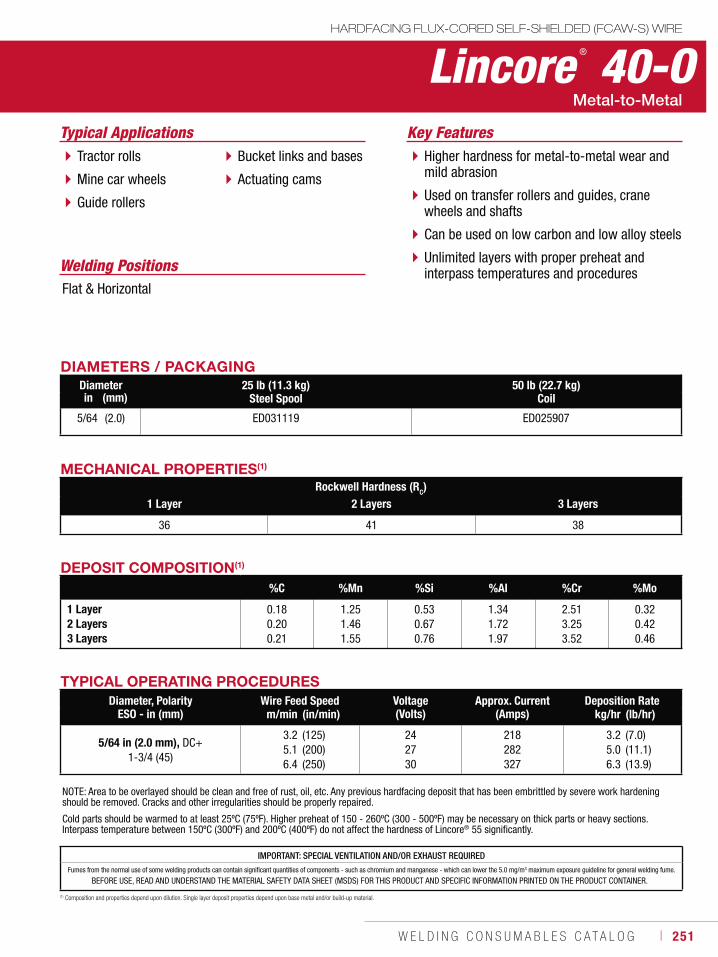
W E L D I N G C O N S U M A B L E S C A T A L O G ı 251
Lincore ® 40-OHARDFACING FLUX-CORED SELF-SHIELDED (FCAW-S) WIRE
Welding Positions
Typical Applications
Flat & Horizontal
Tractor rolls
Mine car wheels
Guide rollers
Bucket links and bases
Actuating cams
Higher hardness for metal-to-metal wear and mild abrasion
Used on transfer rollers and guides, crane wheels and shafts
Can be used on low carbon and low alloy steels
Unlimited layers with proper preheat and interpass temperatures and procedures
Key Features
DIAMETERS / PACKAGINGDiameter 25 lb (11.3 kg)
Steel Spool50 lb (22.7 kg)
Coilin (mm)
5/64 (2.0) ED031119 ED025907
DEPOSIT COMPOSITION(1)
%C %Mn %Si %Al %Cr %Mo
1 Layer2 Layers3 Layers
0.180.200.21
1.251.461.55
0.530.670.76
1.341.721.97
2.513.253.52
0.320.420.46
(1) Composition and properties depend upon dilution. Single layer deposit properties depend upon base metal and/or build-up material.
MECHANICAL PROPERTIES(1)
Rockwell Hardness (RC)1 Layer 2 Layers 3 Layers
36 41 38
IMPORTANT: SPECIAL VENTILATION AND/OR EXHAUST REQUIREDFumes from the normal use of some welding products can contain significant quantities of components - such as chromium and manganese - which can lower the 5.0 mg/m3 maximum exposure guideline for general welding fume.
BEFORE USE, READ AND UNDERSTAND THE MATERIAL SAFETY DATA SHEET (MSDS) FOR THIS PRODUCT AND SPECIFIC INFORMATION PRINTED ON THE PRODUCT CONTAINER.
NOTE: Area to be overlayed should be clean and free of rust, oil, etc. Any previous hardfacing deposit that has been embrittled by severe work hardening should be removed. Cracks and other irregularities should be properly repaired.
Cold parts should be warmed to at least 25ºC (75ºF). Higher preheat of 150 - 260ºC (300 - 500ºF) may be necessary on thick parts or heavy sections. Interpass temperature between 150ºC (300ºF) and 200ºC (400ºF) do not affect the hardness of Lincore® 55 significantly.
TYPICAL OPERATING PROCEDURESDiameter, Polarity
ESO - in (mm)Wire Feed Speed Voltage
(Volts)Approx. Current
(Amps)Deposition Rate
m/min (in/min) kg/hr (lb/hr)
5/64 in (2.0 mm), DC+ 1-3/4 (45)
3.25.16.4
(125)(200)(250)
242730
218282327
3.25.06.3
(7.0)(11.1)(13.9)
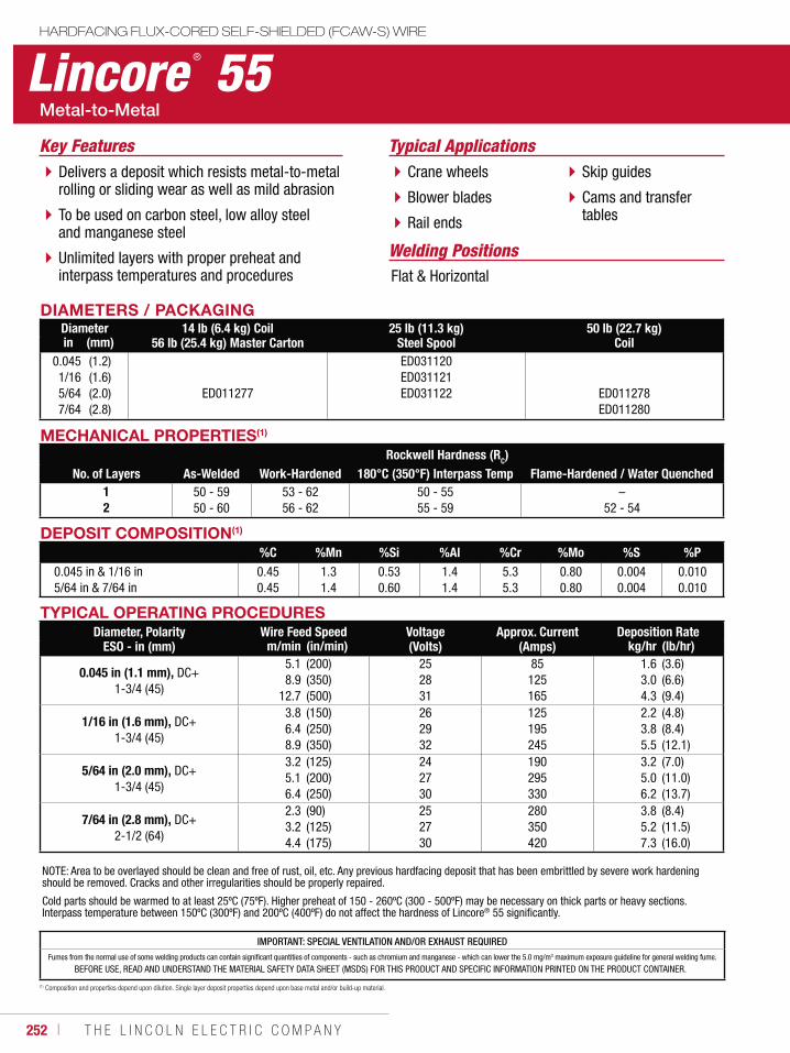
252 ı T H E L I N C O L N E L E C T R I C C O M P A N Y
IMPORTANT: SPECIAL VENTILATION AND/OR EXHAUST REQUIREDFumes from the normal use of some welding products can contain significant quantities of components - such as chromium and manganese - which can lower the 5.0 mg/m3 maximum exposure guideline for general welding fume.
BEFORE USE, READ AND UNDERSTAND THE MATERIAL SAFETY DATA SHEET (MSDS) FOR THIS PRODUCT AND SPECIFIC INFORMATION PRINTED ON THE PRODUCT CONTAINER.
Lincore ® 55HARDFACING FLUX-CORED SELF-SHIELDED (FCAW-S) WIRE
Welding Positions
Typical Applications
Flat & Horizontal
Crane wheels
Blower blades
Rail ends
Skip guides
Cams and transfer tables
Delivers a deposit which resists metal-to-metal rolling or sliding wear as well as mild abrasion
To be used on carbon steel, low alloy steel and manganese steel
Unlimited layers with proper preheat and interpass temperatures and procedures
Key Features
DIAMETERS / PACKAGINGDiameter 14 lb (6.4 kg) Coil
56 lb (25.4 kg) Master Carton25 lb (11.3 kg)
Steel Spool50 lb (22.7 kg)
Coilin (mm)0.0451/16 5/647/64
(1.2)(1.6)(2.0)(2.8)
ED011277
ED031120ED031121ED031122 ED011278
ED011280
MECHANICAL PROPERTIES(1)
Rockwell Hardness (RC)No. of Layers As-Welded Work-Hardened 180°C (350°F) Interpass Temp Flame-Hardened / Water Quenched
12
50 - 5950 - 60
53 - 6256 - 62
50 - 5555 - 59
–52 - 54
DEPOSIT COMPOSITION(1)
%C %Mn %Si %Al %Cr %Mo %S %P0.045 in & 1/16 in5/64 in & 7/64 in
0.450.45
1.31.4
0.530.60
1.41.4
5.35.3
0.800.80
0.0040.004
0.0100.010
(1) Composition and properties depend upon dilution. Single layer deposit properties depend upon base metal and/or build-up material.
TYPICAL OPERATING PROCEDURESDiameter, Polarity
ESO - in (mm)Wire Feed Speed Voltage
(Volts)Approx. Current
(Amps)Deposition Rate
m/min (in/min) kg/hr (lb/hr)
0.045 in (1.1 mm), DC+ 1-3/4 (45)
5.18.9
12.7
(200)(350)(500)
252831
85125165
1.63.04.3
(3.6)(6.6)(9.4)
1/16 in (1.6 mm), DC+ 1-3/4 (45)
3.86.48.9
(150)(250)(350)
262932
125195245
2.23.85.5
(4.8)(8.4)(12.1)
5/64 in (2.0 mm), DC+ 1-3/4 (45)
3.25.16.4
(125)(200)(250)
242730
190295330
3.25.06.2
(7.0)(11.0)(13.7)
7/64 in (2.8 mm), DC+ 2-1/2 (64)
2.33.24.4
(90)(125)(175)
252730
280350420
3.85.27.3
(8.4)(11.5)(16.0)
NOTE: Area to be overlayed should be clean and free of rust, oil, etc. Any previous hardfacing deposit that has been embrittled by severe work hardening should be removed. Cracks and other irregularities should be properly repaired.
Cold parts should be warmed to at least 25ºC (75ºF). Higher preheat of 150 - 260ºC (300 - 500ºF) may be necessary on thick parts or heavy sections. Interpass temperature between 150ºC (300ºF) and 200ºC (400ºF) do not affect the hardness of Lincore® 55 significantly.
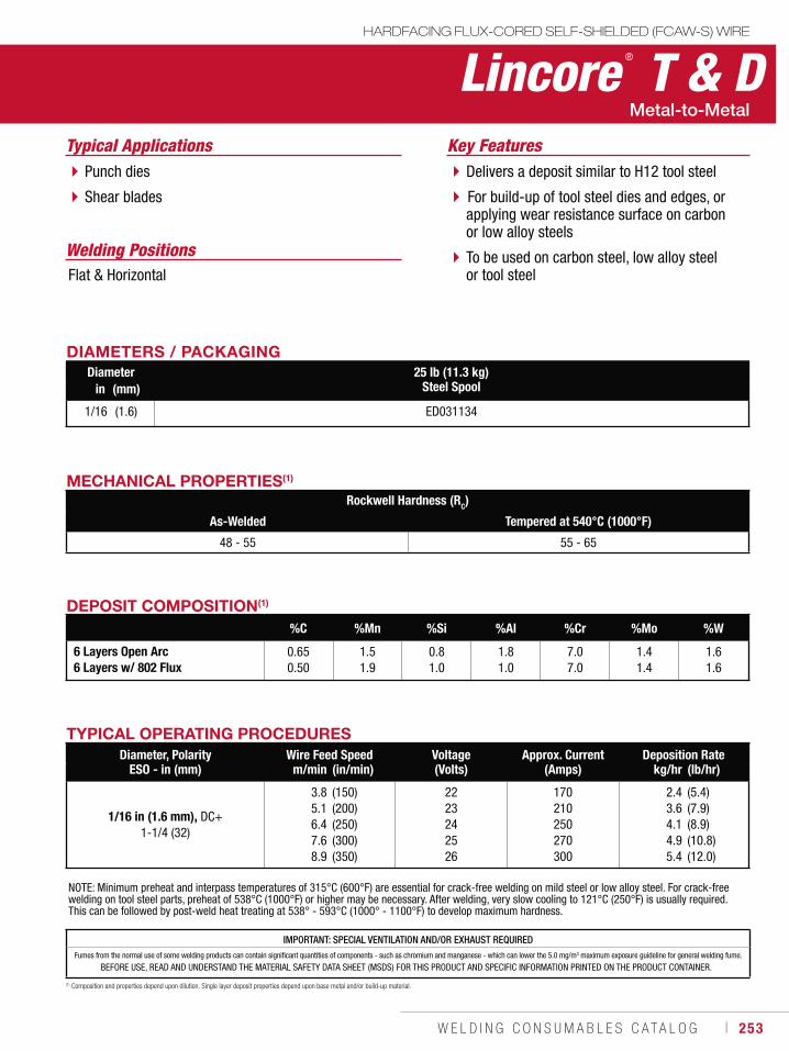
W E L D I N G C O N S U M A B L E S C A T A L O G ı 253
Lincore ® T & DHARDFACING FLUX-CORED SELF-SHIELDED (FCAW-S) WIRE
Welding Positions
Typical Applications
Flat & Horizontal
Punch dies
Shear blades
Delivers a deposit similar to H12 tool steel
For build-up of tool steel dies and edges, or applying wear resistance surface on carbon or low alloy steels
To be used on carbon steel, low alloy steel or tool steel
Key Features
DIAMETERS / PACKAGINGDiameter 25 lb (11.3 kg)
Steel Spoolin (mm)
1/16 (1.6) ED031134
MECHANICAL PROPERTIES(1)
Rockwell Hardness (RC)
As-Welded Tempered at 540°C (1000°F)
48 - 55 55 - 65
DEPOSIT COMPOSITION(1)
%C %Mn %Si %Al %Cr %Mo %W
6 Layers Open Arc6 Layers w/ 802 Flux
0.650.50
1.51.9
0.81.0
1.81.0
7.07.0
1.41.4
1.61.6
(1) Composition and properties depend upon dilution. Single layer deposit properties depend upon base metal and/or build-up material.
TYPICAL OPERATING PROCEDURESDiameter, Polarity
ESO - in (mm)Wire Feed Speed Voltage
(Volts)Approx. Current
(Amps)Deposition Rate
m/min (in/min) kg/hr (lb/hr)
1/16 in (1.6 mm), DC+ 1-1/4 (32)
3.85.16.47.68.9
(150)(200)(250)(300)(350)
2223242526
170210250270300
2.43.64.14.95.4
(5.4)(7.9)(8.9)(10.8)(12.0)
NOTE: Minimum preheat and interpass temperatures of 315°C (600°F) are essential for crack-free welding on mild steel or low alloy steel. For crack-free welding on tool steel parts, preheat of 538°C (1000°F) or higher may be necessary. After welding, very slow cooling to 121°C (250°F) is usually required. This can be followed by post-weld heat treating at 538° - 593°C (1000° - 1100°F) to develop maximum hardness.
IMPORTANT: SPECIAL VENTILATION AND/OR EXHAUST REQUIREDFumes from the normal use of some welding products can contain significant quantities of components - such as chromium and manganese - which can lower the 5.0 mg/m3 maximum exposure guideline for general welding fume.
BEFORE USE, READ AND UNDERSTAND THE MATERIAL SAFETY DATA SHEET (MSDS) FOR THIS PRODUCT AND SPECIFIC INFORMATION PRINTED ON THE PRODUCT CONTAINER.
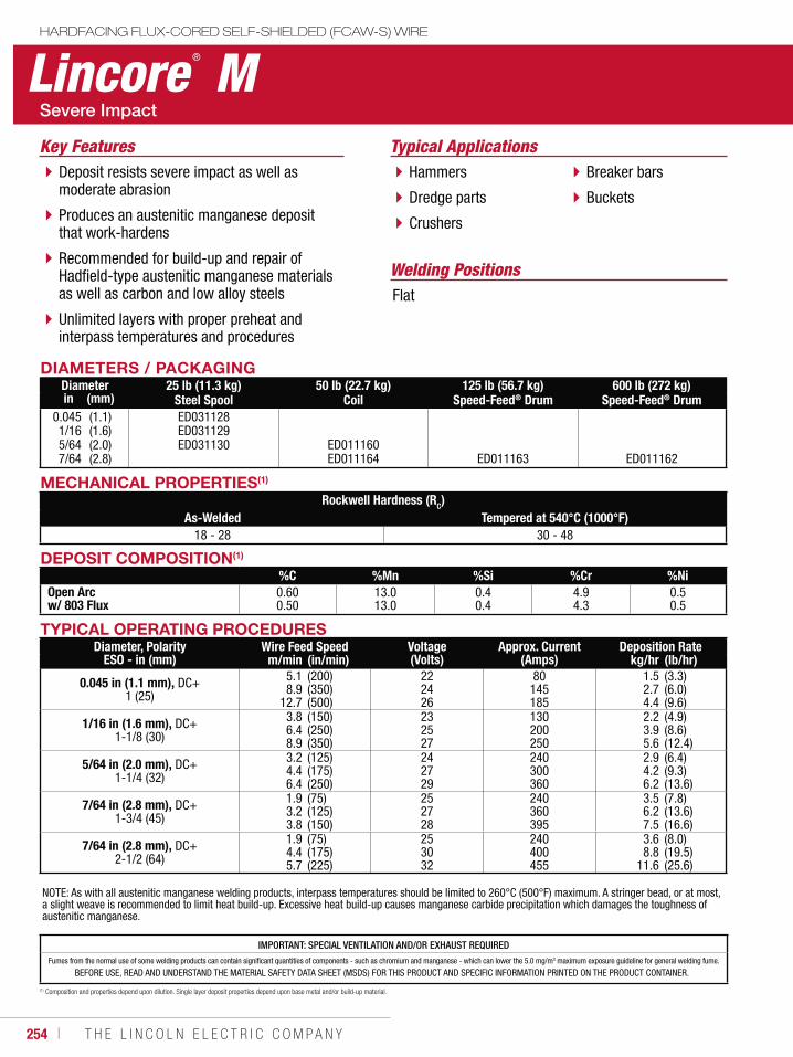
254 ı T H E L I N C O L N E L E C T R I C C O M P A N Y
DEPOSIT COMPOSITION(1)
%C %Mn %Si %Cr %NiOpen Arcw/ 803 Flux
0.600.50
13.013.0
0.40.4
4.94.3
0.50.5
IMPORTANT: SPECIAL VENTILATION AND/OR EXHAUST REQUIREDFumes from the normal use of some welding products can contain significant quantities of components - such as chromium and manganese - which can lower the 5.0 mg/m3 maximum exposure guideline for general welding fume.
BEFORE USE, READ AND UNDERSTAND THE MATERIAL SAFETY DATA SHEET (MSDS) FOR THIS PRODUCT AND SPECIFIC INFORMATION PRINTED ON THE PRODUCT CONTAINER.
Lincore ® MHARDFACING FLUX-CORED SELF-SHIELDED (FCAW-S) WIRE
Welding Positions
Typical Applications
Flat
Hammers
Dredge parts
Crushers
Breaker bars
Buckets
Deposit resists severe impact as well as moderate abrasion
Produces an austenitic manganese deposit that work-hardens
Recommended for build-up and repair of Hadfield-type austenitic manganese materials as well as carbon and low alloy steels
Unlimited layers with proper preheat and interpass temperatures and procedures
Key Features
DIAMETERS / PACKAGINGDiameter 25 lb (11.3 kg)
Steel Spool50 lb (22.7 kg)
Coil125 lb (56.7 kg)
Speed-Feed® Drum600 lb (272 kg)
Speed-Feed® Drumin (mm)0.0451/165/647/64
(1.1)(1.6)(2.0)(2.8)
ED031128ED031129ED031130 ED011160
ED011164 ED011163 ED011162
(1) Composition and properties depend upon dilution. Single layer deposit properties depend upon base metal and/or build-up material.
MECHANICAL PROPERTIES(1)
Rockwell Hardness (RC)As-Welded Tempered at 540°C (1000°F)
18 - 28 30 - 48
TYPICAL OPERATING PROCEDURESDiameter, Polarity
ESO - in (mm)Wire Feed Speed Voltage
(Volts)Approx. Current
(Amps)Deposition Rate
m/min (in/min) kg/hr (lb/hr)
0.045 in (1.1 mm), DC+ 1 (25)
5.18.9
12.7
(200)(350)(500)
222426
80145185
1.52.74.4
(3.3)(6.0)(9.6)
1/16 in (1.6 mm), DC+1-1/8 (30)
3.86.48.9
(150)(250)(350)
232527
130200250
2.23.95.6
(4.9)(8.6)(12.4)
5/64 in (2.0 mm), DC+1-1/4 (32)
3.24.46.4
(125)(175)(250)
242729
240300360
2.94.26.2
(6.4)(9.3)(13.6)
7/64 in (2.8 mm), DC+1-3/4 (45)
1.93.23.8
(75)(125)(150)
252728
240360395
3.56.27.5
(7.8)(13.6)(16.6)
7/64 in (2.8 mm), DC+2-1/2 (64)
1.94.45.7
(75)(175)(225)
253032
240400455
3.68.8
11.6
(8.0)(19.5)(25.6)
NOTE: As with all austenitic manganese welding products, interpass temperatures should be limited to 260°C (500°F) maximum. A stringer bead, or at most, a slight weave is recommended to limit heat build-up. Excessive heat build-up causes manganese carbide precipitation which damages the toughness of austenitic manganese.
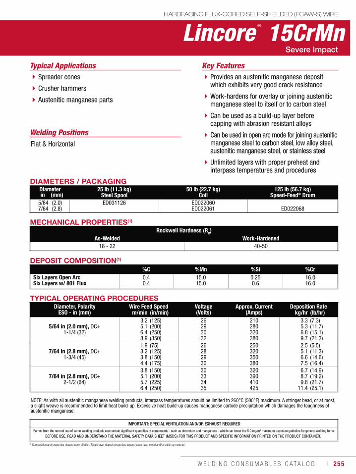
W E L D I N G C O N S U M A B L E S C A T A L O G ı 255
Lincore ® 15CrMnHARDFACING FLUX-CORED SELF-SHIELDED (FCAW-S) WIRE
Welding Positions
Typical Applications
Flat & Horizontal
Spreader cones
Crusher hammers
Austenitic manganese parts
Provides an austenitic manganese deposit which exhibits very good crack resistance
Work-hardens for overlay or joining austenitic manganese steel to itself or to carbon steel
Can be used as a build-up layer before capping with abrasion resistant alloys
Can be used in open arc mode for joining austenitic manganese steel to carbon steel, low alloy steel, austenitic manganese steel, or stainless steel
Unlimited layers with proper preheat and interpass temperatures and procedures
Key Features
DIAMETERS / PACKAGINGDiameter 25 lb (11.3 kg)
Steel Spool50 lb (22.7 kg)
Coil125 lb (56.7 kg)
Speed-Feed® Drumin (mm)5/647/64
(2.0)(2.8)
ED031126 ED022060ED022061 ED022068
DEPOSIT COMPOSITION(1)
%C %Mn %Si %CrSix Layers Open ArcSix Layers w/ 801 Flux
0.40.4
15.015.0
0.250.6
16.016.0
(1) Composition and properties depend upon dilution. Single layer deposit properties depend upon base metal and/or build-up material.
MECHANICAL PROPERTIES(1)
Rockwell Hardness (RC)As-Welded Work-Hardened
18 - 22 40-50
IMPORTANT: SPECIAL VENTILATION AND/OR EXHAUST REQUIREDFumes from the normal use of some welding products can contain significant quantities of components - such as chromium and manganese - which can lower the 5.0 mg/m3 maximum exposure guideline for general welding fume.
BEFORE USE, READ AND UNDERSTAND THE MATERIAL SAFETY DATA SHEET (MSDS) FOR THIS PRODUCT AND SPECIFIC INFORMATION PRINTED ON THE PRODUCT CONTAINER.
TYPICAL OPERATING PROCEDURESDiameter, Polarity
ESO - in (mm)Wire Feed Speed Voltage
(Volts)Approx. Current
(Amps)Deposition Rate
m/min (in/min) kg/hr (lb/hr)
5/64 in (2.0 mm), DC+1-1/4 (32)
3.25.16.48.9
(125)(200)(250)(350)
26293032
210280320380
3.35.36.89.7
(7.3)(11.7)(15.1)(21.3)
7/64 in (2.8 mm), DC+1-3/4 (45)
1.93.23.84.4
(75)(125)(150)(175)
26282930
250320350380
2.55.16.67.5
(5.5)(11.3)(14.6)(16.4)
7/64 in (2.8 mm), DC+2-1/2 (64)
3.85.15.76.4
(150)(200)(225)(250)
30333435
320390410425
6.78.79.8
11.4
(14.9)(19.2)(21.7)(25.1)
NOTE: As with all austenitic manganese welding products, interpass temperatures should be limited to 260°C (500°F) maximum. A stringer bead, or at most, a slight weave is recommended to limit heat build-up. Excessive heat build-up causes manganese carbide precipitation which damages the toughness of austenitic manganese.
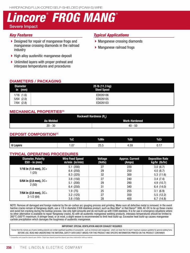
256 ı T H E L I N C O L N E L E C T R I C C O M P A N Y
IMPORTANT: SPECIAL VENTILATION AND/OR EXHAUST REQUIREDFumes from the normal use of some welding products can contain significant quantities of components - such as chromium and manganese - which can lower the 5.0 mg/m3 maximum exposure guideline for general welding fume.
BEFORE USE, READ AND UNDERSTAND THE MATERIAL SAFETY DATA SHEET (MSDS) FOR THIS PRODUCT AND SPECIFIC INFORMATION PRINTED ON THE PRODUCT CONTAINER.
Lincore ® FROG MANG ®
HARDFACING FLUX-CORED SELF-SHIELDED (FCAW-S) WIRE
Typical ApplicationsManganese crossing diamonds
Manganese railroad frogs
Designed for repair of manganese frogs and manganese crossing diamonds in the railroad industry
High alloy austenitic manganese deposit
Unlimited layers with proper preheat and interpass temperatures and procedures
Key Features
DIAMETERS / PACKAGINGDiameter 25 lb (11.3 kg)
Steel Spoolin (mm)
1/165/647/64
(1.6)(2.0)(2.8)
ED026106ED026105ED026103
MECHANICAL PROPERTIES(1)
Rockwell Hardness (RC)As-Welded Work-Hardened
20 - 30 40 - 50
DEPOSIT COMPOSITION(1)
%C %Mn %Si %Cr
6 Layers 1.07 25.5 4.59 0.17
(1) Composition and properties depend upon dilution. Single layer deposit properties depend upon base metal and/or build-up material.
TYPICAL OPERATING PROCEDURESDiameter, Polarity
ESO - in (mm)Wire Feed Speed Voltage
(Volts)Approx. Current
(Amps)Deposition Rate
m/min (in/min) kg/hr (lb/hr)
1/16 in (1.6 mm), DC+1 (25)
5.16.48.3
(200)(250)(325)
272932
220250300
3.04.05.3
(6.7)(8.7)(11.6)
5/64 in (2.0 mm), DC+2 (50)
3.85.16.4
(150)(200)(250)
272931
240290340
3.44.96.4
(7.4)(10.7)(14.0)
7/64 in (2.8 mm), DC+2-1/2 (64)
1.93.23.8
(75)(125)(150)
252728
255350400
3.15.56.7
(6.9)(12.2)(14.8)
NOTE: Remove all damaged and foreign material by the air-carbon arc gouging process and grinding. Make sure all defective metal is removed. In the event hairline cracks remain at flangeway depth, use a 1/8 in diameter E308 stainless product, such as Blue Max® or Red Baron® 308L AC-DC to tie up these cracksand avoid hot cracking during the buildup process. Use only light amounts and do not build-up with E308 stainless. It is for use in emergency situations where no other alternative is available to repair flangeway cracks. As with all austenitic manganese welding products, interpass temperatures should be limited to 260°C (500°F) maximum. A stringer bead, or at most, a slight weave is recommended to limit heat build-up. Excessive heat build-up causes manganese carbide precipitation which damages the toughness of austenitic manganese.
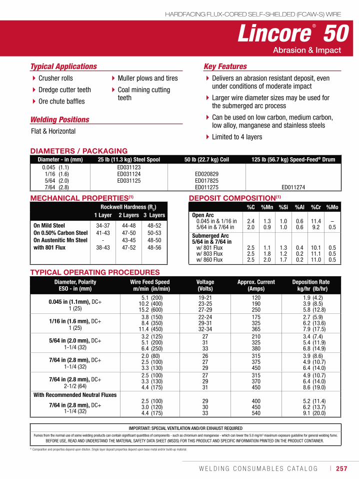
W E L D I N G C O N S U M A B L E S C A T A L O G ı 257
Lincore ® 50HARDFACING FLUX-CORED SELF-SHIELDED (FCAW-S) WIRE
Welding Positions
Typical Applications
Flat & Horizontal
Crusher rolls
Dredge cutter teeth
Ore chute baffles
Muller plows and tires
Coal mining cutting teeth
Delivers an abrasion resistant deposit, even under conditions of moderate impact
Larger wire diameter sizes may be used for the submerged arc process
Can be used on low carbon, medium carbon, low alloy, manganese and stainless steels
Limited to 4 layers
Key Features
DIAMETERS / PACKAGINGDiameter - in (mm) 25 lb (11.3 kg) Steel Spool 50 lb (22.7 kg) Coil 125 lb (56.7 kg) Speed-Feed® Drum
0.0451/165/647/64
(1.1)(1.6)(2.0)(2.8)
ED031123ED031124ED031125
ED020829ED017825ED011275 ED011274
MECHANICAL PROPERTIES(1)
Rockwell Hardness (RC)1 Layer 2 Layers 3 Layers
On Mild SteelOn 0.50% Carbon SteelOn Austenitic Mn Steelwith 801 Flux
34-3741-43
-38-43
44-4847-5043-4547-52
48-5250-5348-5048-56
DEPOSIT COMPOSITION(1)
%C %Mn %Si %Al %Cr %MoOpen Arc 0.045 in & 1/16 in 5/64 in & 7/64 in
2.42.0
1.30.9
1.01.0
0.60.6
11.49.2
–0.5
Submerged Arc 5/64 in & 7/64 in w/ 801 Flux w/ 803 Flux w/ 860 Flux
2.52.52.5
1.11.82.0
1.31.21.7
0.40.20.2
10.111.111.0
0.50.50.5
(1) Composition and properties depend upon dilution. Single layer deposit properties depend upon base metal and/or build-up material.
TYPICAL OPERATING PROCEDURESDiameter, Polarity
ESO - in (mm)Wire Feed Speed Voltage
(Volts)Approx. Current
(Amps)Deposition Rate
m/min (in/min) kg/hr (lb/hr)
0.045 in (1.1mm), DC+ 1 (25)
5.110.215.2
(200)(400)(600)
19-2123-2527-29
120190250
1.93.95.8
(4.2)(8.5)(12.8)
1/16 in (1.6 mm), DC+ 1 (25)
3.88.4
11.4
(150)(350)(450)
22-2429-3132-34
175325365
2.76.27.9
(5.9)(13.6)(17.5)
5/64 in (2.0 mm), DC+ 1-1/4 (32)
3.25.16.4
(125)(200)(250)
273133
210325380
3.45.46.8
(7.4)(11.9)(14.9)
7/64 in (2.8 mm), DC+ 1-1/4 (32)
2.02.53.3
(80)(100)(130)
262729
315375450
3.94.96.4
(8.6)(10.7)(14.0)
7/64 in (2.8 mm), DC+ 2-1/2 (64)
2.53.34.4
(100)(130)(175)
272931
315370450
4.96.48.6
(10.7)(14.0)(19.0)
With Recommended Neutral Fluxes
7/64 in (2.8 mm), DC+ 1-1/4 (32)
2.53.04.4
(100)(120)(175)
293033
400450540
5.26.29.1
(11.4)(13.7)(20.0)
IMPORTANT: SPECIAL VENTILATION AND/OR EXHAUST REQUIREDFumes from the normal use of some welding products can contain significant quantities of components - such as chromium and manganese - which can lower the 5.0 mg/m3 maximum exposure guideline for general welding fume.
BEFORE USE, READ AND UNDERSTAND THE MATERIAL SAFETY DATA SHEET (MSDS) FOR THIS PRODUCT AND SPECIFIC INFORMATION PRINTED ON THE PRODUCT CONTAINER.
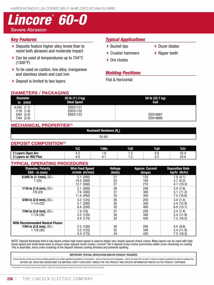
258 ı T H E L I N C O L N E L E C T R I C C O M P A N Y
IMPORTANT: SPECIAL VENTILATION AND/OR EXHAUST REQUIREDFumes from the normal use of some welding products can contain significant quantities of components - such as chromium and manganese - which can lower the 5.0 mg/m3 maximum exposure guideline for general welding fume.
BEFORE USE, READ AND UNDERSTAND THE MATERIAL SAFETY DATA SHEET (MSDS) FOR THIS PRODUCT AND SPECIFIC INFORMATION PRINTED ON THE PRODUCT CONTAINER.
Lincore ® 60-OHARDFACING FLUX-CORED SELF-SHIELDED (FCAW-S) WIRE
Welding Positions
Typical Applications
Flat & Horizontal
Bucket lips
Crusher hammers
Ore chutes
Dozer blades
Ripper teeth
Deposits feature higher alloy levels than to resist both abrasion and moderate impact
Can be used at temperatures up to 704°C (1300°F)
To be used on carbon, low alloy, manganese and stainless steels and cast iron
Deposit is limited to two layers
Key Features
DIAMETERS / PACKAGINGDiameter 25 lb (11.3 kg)
Steel Spool50 lb (22.7 kg)
Coilin (mm)0.0451/165/647/64
(1.1)(1.6)(2.0)(2.8)
ED031131ED031132ED031133 ED019887
ED019888
MECHANICAL PROPERTIES(1)
Rockwell Hardness (RC)
55-60
DEPOSIT COMPOSITION(1)
%C %Mn %Si %Al %Cr2 Layers Open Arc2 Layers w/ 803 Flux
4.24.8
1.64.1
1.31.2
0.60.2
25.425.8
(1) Composition and properties depend upon dilution. Single layer deposit properties depend upon base metal and/or build-up material.
TYPICAL OPERATING PROCEDURESDiameter, Polarity
ESO - in (mm)Wire Feed Speed Voltage
(Volts)Approx. Current
(Amps)Deposition Rate
m/min (in/min) kg/hr (lb/hr)0.045 in (1.1mm), DC+
1 (25)5.1
10.212.7
(200)(400)(500)
212527
125185210
1.93.74.7
(4.1)(8.2)(10.3)
1/16 in (1.6 mm), DC+ 7/8 (22)
5.17.6
11.4
(200)(300)(450)
283133
240300350
3.45.17.5
(7.6)(11.2)(16.6)
5/64 in (2.0 mm), DC+ 1-1/4 (32)
3.25.16.4
(125)(200)(250)
263032
250350400
3.45.46.9
(7.4)(12.0)(15.1)
7/64 in (2.8 mm), DC+ 1-1/8 (30)
1.93.24.4
(75)(125)(175)
273032
250340420
3.45.47.5
(7.4)(11.9)(16.5)
With Recommended Neutral Fluxes7/64 in (2.8 mm), DC+
1-1/8 (30)2.53.24.4
(100)(125)(175)
303234
295340420
4.45.47.5
(9.6)(11.9)(16.5)
NOTE: Deposit thickness limit is two layers unless high travel speed is used to obtain very closely spaced check cracks. Many layers can be used with high travel speed and small bead sizes to ensure close-spaced check cracks. Lincore® 60-0 deposit cross cracks (commonly called cross-checking) on cooling. This is desirable, since cross-cracking of the deposit relieves cooling stresses and prevents spalling.
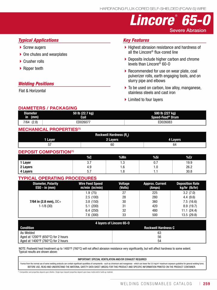
W E L D I N G C O N S U M A B L E S C A T A L O G ı 259
DEPOSIT COMPOSITION(1)
%C %Mn %Si %Cr1 Layer2 Layers4 Layers
3.74.95.7
1.31.61.8
0.71.01.1
19.926.230.8
Lincore ® 65-OHARDFACING FLUX-CORED SELF-SHIELDED (FCAW-S) WIRE
Welding Positions
Typical Applications
Flat & Horizontal
Screw augers
Ore chutes and wearplates
Crusher rolls
Ripper teeth
Highest abrasion resistance and hardness of all the Lincore® flux-cored line
Deposits include higher carbon and chrome levels than Lincore® 60-O
Recommended for use on wear plate, coal pulverizer rolls, earth engaging tools, and on slurry pipe and elbows
To be used on carbon, low alloy, manganese, stainless steels and cast iron
Limited to four layers
Key Features
DIAMETERS / PACKAGINGDiameter 50 lb (22.7 kg)
Coil500 lb (227 kg)
Speed-Feed® Drumin (mm)7/64 (2.8) ED026077 ED026083
MECHANICAL PROPERTIES(1)
Rockwell Hardness (RC)1 Layer 2 Layers 4 Layers
57 60 64
(1) Composition and properties depend upon dilution. Single layer deposit properties depend upon base metal and/or build-up material.
TYPICAL OPERATING PROCEDURESDiameter, Polarity
ESO - in (mm)Wire Feed Speed Voltage
(Volts)Approx. Current
(Amps)Deposition Rate
m/min (in/min) kg/hr (lb/hr)
7/64 in (2.8 mm), DC+ 1-1/8 (30)
1.92.53.85.16.47.6
(75)(100)(150)(200)(250)(300)
272830313233
225280360420480500
3.24.47.58.9
11.113.5
(7.0)(9.6)(16.6)(19.7)(24.4)(29.8)
NOTE: Postweld heat treatment up to 1400°F (760°C) will not affect abrasion resistance very significantly, but will affect hardness to some extent. Typical results are shown above:
4 layers of Lincore 65-OCondition Rockwell Hardness CAs-WeldedAged at 1200°F (650°C) for 2 hoursAged at 1400°F (760°C) for 2 hours
6356 54
IMPORTANT: SPECIAL VENTILATION AND/OR EXHAUST REQUIREDFumes from the normal use of some welding products can contain significant quantities of components - such as chromium and manganese - which can lower the 5.0 mg/m3 maximum exposure guideline for general welding fume.
BEFORE USE, READ AND UNDERSTAND THE MATERIAL SAFETY DATA SHEET (MSDS) FOR THIS PRODUCT AND SPECIFIC INFORMATION PRINTED ON THE PRODUCT CONTAINER.
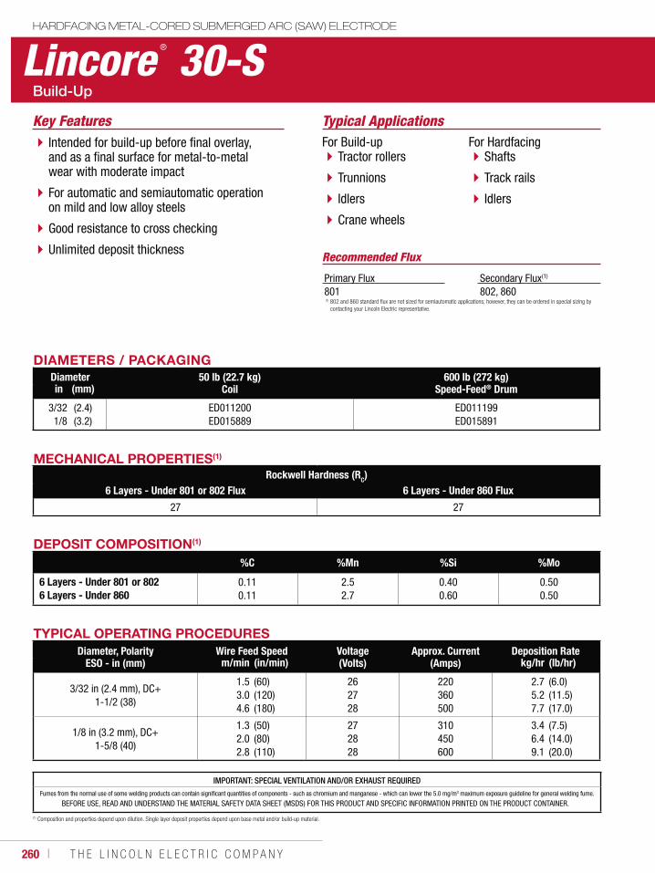
260 ı T H E L I N C O L N E L E C T R I C C O M P A N Y
IMPORTANT: SPECIAL VENTILATION AND/OR EXHAUST REQUIREDFumes from the normal use of some welding products can contain significant quantities of components - such as chromium and manganese - which can lower the 5.0 mg/m3 maximum exposure guideline for general welding fume.
BEFORE USE, READ AND UNDERSTAND THE MATERIAL SAFETY DATA SHEET (MSDS) FOR THIS PRODUCT AND SPECIFIC INFORMATION PRINTED ON THE PRODUCT CONTAINER.
Lincore ® 30-SHARDFACING METAL-CORED SUBMERGED ARC (SAW) ELECTRODE
Typical ApplicationsFor Build-up
Tractor rollers
Trunnions
Idlers
Crane wheels
For HardfacingShafts
Track rails
Idlers
Intended for build-up before final overlay, and as a final surface for metal-to-metal wear with moderate impact
For automatic and semiautomatic operation on mild and low alloy steels
Good resistance to cross checking
Unlimited deposit thickness
Key Features
Recommended Flux
Primary Flux801
Secondary Flux(1)
802, 860
DIAMETERS / PACKAGINGDiameter 50 lb (22.7 kg)
Coil600 lb (272 kg)
Speed-Feed® Drumin (mm)
3/321/8
(2.4)(3.2)
ED011200ED015889
ED011199ED015891
(1) 802 and 860 standard flux are not sized for semiautomatic applications; however, they can be ordered in special sizing by contacting your Lincoln Electric representative.
DEPOSIT COMPOSITION(1)
%C %Mn %Si %Mo
6 Layers - Under 801 or 8026 Layers - Under 860
0.110.11
2.52.7
0.400.60
0.500.50
(1) Composition and properties depend upon dilution. Single layer deposit properties depend upon base metal and/or build-up material.
MECHANICAL PROPERTIES(1)
Rockwell Hardness (RC)6 Layers - Under 801 or 802 Flux 6 Layers - Under 860 Flux
27 27
TYPICAL OPERATING PROCEDURESDiameter, Polarity
ESO - in (mm)Wire Feed Speed Voltage
(Volts)Approx. Current
(Amps)Deposition Rate
m/min (in/min) kg/hr (lb/hr)
3/32 in (2.4 mm), DC+ 1-1/2 (38)
1.53.04.6
(60)(120)(180)
262728
220360500
2.75.27.7
(6.0)(11.5)(17.0)
1/8 in (3.2 mm), DC+ 1-5/8 (40)
1.32.02.8
(50)(80)(110)
272828
310450600
3.46.49.1
(7.5)(14.0)(20.0)
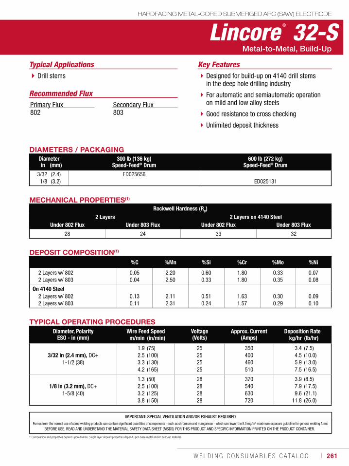
W E L D I N G C O N S U M A B L E S C A T A L O G ı 261
Drill stems
Lincore ® 32-SHARDFACING METAL-CORED SUBMERGED ARC (SAW) ELECTRODE
Typical ApplicationsDesigned for build-up on 4140 drill stems in the deep hole drilling industry
For automatic and semiautomatic operation on mild and low alloy steels
Good resistance to cross checking
Unlimited deposit thickness
Key Features
DIAMETERS / PACKAGINGDiameter 300 lb (136 kg)
Speed-Feed® Drum600 lb (272 kg)
Speed-Feed® Drumin (mm)
3/321/8
(2.4)(3.2)
ED025656ED025131
Recommended FluxPrimary Flux802
Secondary Flux803
MECHANICAL PROPERTIES(1)
Rockwell Hardness (RC)2 Layers 2 Layers on 4140 Steel
Under 802 Flux Under 803 Flux Under 802 Flux Under 803 Flux
28 24 33 32
DEPOSIT COMPOSITION(1)
%C %Mn %Si %Cr %Mo %Ni
2 Layers w/ 802 2 Layers w/ 803
0.050.04
2.202.50
0.600.33
1.801.80
0.330.35
0.070.08
On 4140 Steel 2 Layers w/ 802 2 Layers w/ 803
0.130.11
2.112.31
0.510.24
1.631.57
0.300.29
0.090.10
(1) Composition and properties depend upon dilution. Single layer deposit properties depend upon base metal and/or build-up material.
TYPICAL OPERATING PROCEDURESDiameter, Polarity
ESO - in (mm)Wire Feed Speed Voltage
(Volts)Approx. Current
(Amps)Deposition Rate
m/min (in/min) kg/hr (lb/hr)
3/32 in (2.4 mm), DC+ 1-1/2 (38)
1.92.53.34.2
(75)(100)(130)(165)
25252525
350400460510
3.44.55.97.5
(7.5)(10.0)(13.0)(16.5)
1/8 in (3.2 mm), DC+ 1-5/8 (40)
1.32.53.23.8
(50)(100)(125)(150)
28282828
370540630720
3.97.99.6
11.8
(8.5)(17.5)(21.1)(26.0)
IMPORTANT: SPECIAL VENTILATION AND/OR EXHAUST REQUIREDFumes from the normal use of some welding products can contain significant quantities of components - such as chromium and manganese - which can lower the 5.0 mg/m3 maximum exposure guideline for general welding fume.
BEFORE USE, READ AND UNDERSTAND THE MATERIAL SAFETY DATA SHEET (MSDS) FOR THIS PRODUCT AND SPECIFIC INFORMATION PRINTED ON THE PRODUCT CONTAINER.
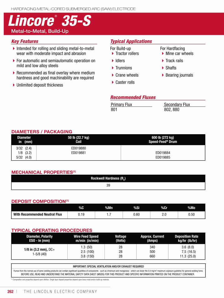
262 ı T H E L I N C O L N E L E C T R I C C O M P A N Y
IMPORTANT: SPECIAL VENTILATION AND/OR EXHAUST REQUIREDFumes from the normal use of some welding products can contain significant quantities of components - such as chromium and manganese - which can lower the 5.0 mg/m3 maximum exposure guideline for general welding fume.
BEFORE USE, READ AND UNDERSTAND THE MATERIAL SAFETY DATA SHEET (MSDS) FOR THIS PRODUCT AND SPECIFIC INFORMATION PRINTED ON THE PRODUCT CONTAINER.
Lincore ® 35-SHARDFACING METAL-CORED SUBMERGED ARC (SAW) ELECTRODE
Typical ApplicationsFor Build-up
Tractor rollers
Idlers
Trunnions
Crane wheels
Caster rolls
For HardfacingMine car wheels
Track rails
Shafts
Bearing journals
Intended for rolling and sliding metal-to-metal wear with moderate impact and abrasion
For automatic and semiautomatic operation on mild and low alloy steels
Recommended as final overlay where medium hardness and good machinability are required
Unlimited deposit thickness
Key Features
Recommended FluxesPrimary Flux801
Secondary Flux802, 880
DIAMETERS / PACKAGINGDiameter 50 lb (22.7 kg)
Coil600 lb (272 kg)
Speed-Feed® Drumin (mm)
3/321/8
5/32
(2.4)(3.2)(4.0)
ED019880ED019881 ED019884
ED019885
MECHANICAL PROPERTIES(1)
Rockwell Hardness (RC)
39
DEPOSIT COMPOSITION(1)
%C %Mn %Si %Cr %Mo
With Recommended Neutral Flux 0.19 1.7 0.60 2.0 0.50
(1) Composition and properties depend upon dilution. Single layer deposit properties depend upon base metal and/or build-up material.
TYPICAL OPERATING PROCEDURESDiameter, Polarity
ESO - in (mm)Wire Feed Speed Voltage
(Volts)Approx. Current
(Amps)Deposition Rate
m/min (in/min) kg/hr (lb/hr)
1/8 in (3.2 mm), DC+ 1-5/8 (40)
1.32.53.8
(50)(100)(150)
282828
340500660
3.67.5
11.3
(8.0)(16.5)(25.0)
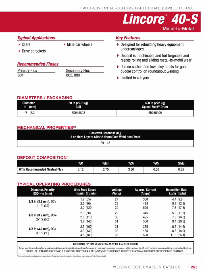
W E L D I N G C O N S U M A B L E S C A T A L O G ı 263
Lincore ® 40-SHARDFACING METAL-CORED SUBMERGED ARC (SAW) ELECTRODE
Typical ApplicationsIdlers
Drive sprockets
Mine car wheels Designed for rebuilding heavy equipment undercarriages
Deposit is machinable and hot forgeable and resists rolling and sliding metal-to-metal wear
Use on carbon and low alloy steels for good puddle control on roundabout welding
Limited to 4 layers
Key Features
DIAMETERS / PACKAGINGDiameter 50 lb (22.7 kg)
Coil600 lb (272 kg)
Speed-Feed® Drumin (mm)
1/8 (3.2) ED015892 ED015909
Recommended FluxesPrimary Flux801
Secondary Flux802, 880
DEPOSIT COMPOSITION(1)
%C %Mn %Si %Cr %Mo
With Recommended Neutral Flux 0.12 2.75 3.30 0.50 0.85
(1) Composition and properties depend upon dilution. Single layer deposit properties depend upon base metal and/or build-up material.
MECHANICAL PROPERTIES(1)
Rockwell Hardness (RC)3 or More Layers After 2 Hours Post Weld Heat Treat
39 - 42
IMPORTANT: SPECIAL VENTILATION AND/OR EXHAUST REQUIREDFumes from the normal use of some welding products can contain significant quantities of components - such as chromium and manganese - which can lower the 5.0 mg/m3 maximum exposure guideline for general welding fume.
BEFORE USE, READ AND UNDERSTAND THE MATERIAL SAFETY DATA SHEET (MSDS) FOR THIS PRODUCT AND SPECIFIC INFORMATION PRINTED ON THE PRODUCT CONTAINER.
TYPICAL OPERATING PROCEDURESDiameter, Polarity
ESO - in (mm)Wire Feed Speed Voltage
(Volts)Approx. Current
(Amps)Deposition Rate
m/min (in/min) kg/hr (lb/hr)
1/8 in (3.2 mm), DC+1-1/4 (32)
1.72.33.0
(65)(90)(120)
272829
330425525
4.45.97.8
(9.6)(12.9)(17.3)
1/8 in (3.2 mm), DC+2-1/2 (65)
2.02.83.7
(80)(110)(145)
293031
345425500
5.27.39.4
(11.5)(16.0)(20.8)
1/8 in (3.2 mm), DC+3-1/2 (90)
2.53.34.6
(100)(130)(180)
313233
375435520
6.58.6
11.9
(14.3)(18.9)(26.1)
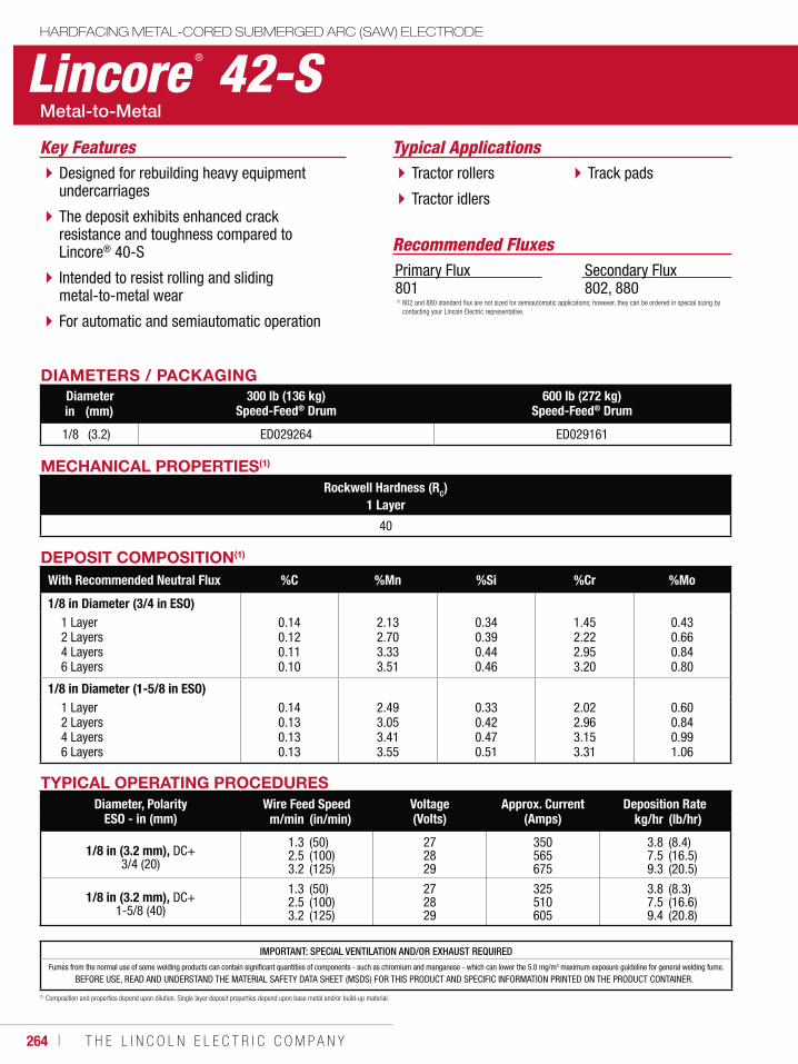
264 ı T H E L I N C O L N E L E C T R I C C O M P A N Y
IMPORTANT: SPECIAL VENTILATION AND/OR EXHAUST REQUIREDFumes from the normal use of some welding products can contain significant quantities of components - such as chromium and manganese - which can lower the 5.0 mg/m3 maximum exposure guideline for general welding fume.
BEFORE USE, READ AND UNDERSTAND THE MATERIAL SAFETY DATA SHEET (MSDS) FOR THIS PRODUCT AND SPECIFIC INFORMATION PRINTED ON THE PRODUCT CONTAINER.
Lincore ® 42-SHARDFACING METAL-CORED SUBMERGED ARC (SAW) ELECTRODE
Typical ApplicationsTractor rollers
Tractor idlers
Track padsDesigned for rebuilding heavy equipment undercarriages
The deposit exhibits enhanced crack resistance and toughness compared to Lincore® 40-S
Intended to resist rolling and sliding metal-to-metal wear
For automatic and semiautomatic operation
Key Features
DIAMETERS / PACKAGINGDiameter 300 lb (136 kg)
Speed-Feed® Drum600 lb (272 kg)
Speed-Feed® Drumin (mm)
1/8 (3.2) ED029264 ED029161
Recommended FluxesPrimary Flux801
Secondary Flux802, 880
MECHANICAL PROPERTIES(1)
Rockwell Hardness (RC)1 Layer
40
DEPOSIT COMPOSITION(1)
With Recommended Neutral Flux %C %Mn %Si %Cr %Mo
1/8 in Diameter (3/4 in ESO) 1 Layer 2 Layers 4 Layers 6 Layers
0.140.120.110.10
2.132.703.333.51
0.340.390.440.46
1.452.222.953.20
0.430.660.840.80
1/8 in Diameter (1-5/8 in ESO) 1 Layer 2 Layers 4 Layers 6 Layers
0.140.130.130.13
2.493.053.413.55
0.330.420.470.51
2.022.963.153.31
0.600.840.991.06
(1) Composition and properties depend upon dilution. Single layer deposit properties depend upon base metal and/or build-up material.
TYPICAL OPERATING PROCEDURESDiameter, Polarity
ESO - in (mm)Wire Feed Speed Voltage
(Volts)Approx. Current
(Amps)Deposition Rate
m/min (in/min) kg/hr (lb/hr)
1/8 in (3.2 mm), DC+3/4 (20)
1.32.53.2
(50)(100)(125)
272829
350565675
3.87.59.3
(8.4)(16.5)(20.5)
1/8 in (3.2 mm), DC+1-5/8 (40)
1.32.53.2
(50)(100)(125)
272829
325510605
3.87.59.4
(8.3)(16.6)(20.8)
(1) 802 and 880 standard flux are not sized for semiautomatic applications; however, they can be ordered in special sizing by contacting your Lincoln Electric representative.
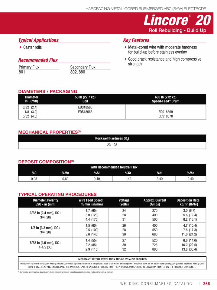
W E L D I N G C O N S U M A B L E S C A T A L O G ı 265
IMPORTANT: SPECIAL VENTILATION AND/OR EXHAUST REQUIREDFumes from the normal use of some welding products can contain significant quantities of components - such as chromium and manganese - which can lower the 5.0 mg/m3 maximum exposure guideline for general welding fume.
BEFORE USE, READ AND UNDERSTAND THE MATERIAL SAFETY DATA SHEET (MSDS) FOR THIS PRODUCT AND SPECIFIC INFORMATION PRINTED ON THE PRODUCT CONTAINER.
Lincore ® 20HARDFACING METAL-CORED SUBMERGED ARC (SAW) ELECTRODE
Typical ApplicationsCaster rolls Metal-cored wire with moderate hardness
for build-up before stainless overlay
Good crack resistance and high compressive strength
Recommended Flux
Key Features
Primary Flux801
Secondary Flux802, 880
DIAMETERS / PACKAGINGDiameter 50 lb (22.7 kg)
Coil600 lb (272 kg)
Speed-Feed® Drumin (mm)
3/321/8
5/32
(2.4)(3.2)(4.0)
EDS18565EDS18566 ED018569
EDS18570
DEPOSIT COMPOSITION(1)
With Recommended Neutral Flux
%C %Mn %Si %Cr %Ni %Mo
0.05 0.60 0.40 1.40 2.40 0.40
(1) Composition and properties depend upon dilution. Single layer deposit properties depend upon base metal and/or build-up material.
MECHANICAL PROPERTIES(1)
Rockwell Hardness (RC)
23 - 28
TYPICAL OPERATING PROCEDURESDiameter, Polarity
ESO - in (mm)Wire Feed Speed Voltage
(Volts)Approx. Current
(Amps)Deposition Rate
m/min (in/min) kg/hr (lb/hr)
3/32 in (2.4 mm), DC+3/4 (20)
1.73.04.4
(65)(120)(175)
242831
270400500
3.05.68.2
(6.7)(12.4)(18.1)
1/8 in (3.2 mm), DC+3/4 (20)
1.52.53.6
(60)(100)(140)
262830
400550680
4.77.8
11.0
(10.4)(17.3)(24.2)
5/32 in (4.0 mm), DC+1-1/2 (38)
1.42.22.9
(55)(85)(115)
273032
520725880
6.610.213.8
(14.6)(22.5)(30.4)
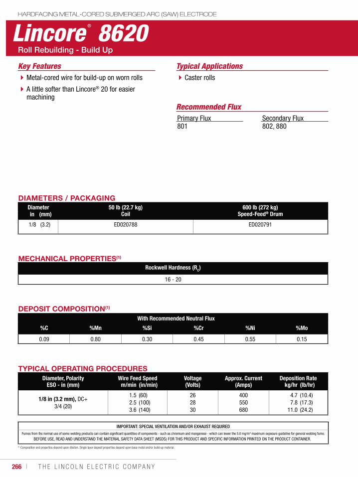
266 ı T H E L I N C O L N E L E C T R I C C O M P A N Y
Lincore ® 8620HARDFACING METAL-CORED SUBMERGED ARC (SAW) ELECTRODE
Typical ApplicationsCaster rollsMetal-cored wire for build-up on worn rolls
A little softer than Lincore® 20 for easier machining
Recommended Flux
Key Features
Primary Flux801
Secondary Flux802, 880
DIAMETERS / PACKAGINGDiameter 50 lb (22.7 kg)
Coil600 lb (272 kg)
Speed-Feed® Drumin (mm)
1/8 (3.2) ED020788 ED020791
MECHANICAL PROPERTIES(1)
Rockwell Hardness (RC)
16 - 20
IMPORTANT: SPECIAL VENTILATION AND/OR EXHAUST REQUIREDFumes from the normal use of some welding products can contain significant quantities of components - such as chromium and manganese - which can lower the 5.0 mg/m3 maximum exposure guideline for general welding fume.
BEFORE USE, READ AND UNDERSTAND THE MATERIAL SAFETY DATA SHEET (MSDS) FOR THIS PRODUCT AND SPECIFIC INFORMATION PRINTED ON THE PRODUCT CONTAINER.
DEPOSIT COMPOSITION(1)
With Recommended Neutral Flux
%C %Mn %Si %Cr %Ni %Mo
0.09 0.80 0.30 0.45 0.55 0.15
(1) Composition and properties depend upon dilution. Single layer deposit properties depend upon base metal and/or build-up material.
TYPICAL OPERATING PROCEDURESDiameter, Polarity
ESO - in (mm)Wire Feed Speed Voltage
(Volts)Approx. Current
(Amps)Deposition Rate
m/min (in/min) kg/hr (lb/hr)
1/8 in (3.2 mm), DC+3/4 (20)
1.52.53.6
(60)(100)(140)
262830
400550680
4.77.8
11.0
(10.4)(17.3)(24.2)
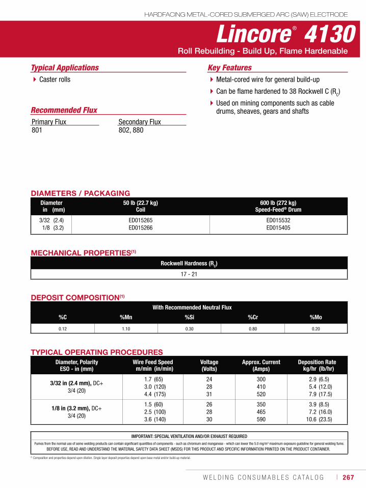
W E L D I N G C O N S U M A B L E S C A T A L O G ı 267
IMPORTANT: SPECIAL VENTILATION AND/OR EXHAUST REQUIREDFumes from the normal use of some welding products can contain significant quantities of components - such as chromium and manganese - which can lower the 5.0 mg/m3 maximum exposure guideline for general welding fume.
BEFORE USE, READ AND UNDERSTAND THE MATERIAL SAFETY DATA SHEET (MSDS) FOR THIS PRODUCT AND SPECIFIC INFORMATION PRINTED ON THE PRODUCT CONTAINER.
Lincore ® 4130HARDFACING METAL-CORED SUBMERGED ARC (SAW) ELECTRODE
Typical ApplicationsCaster rolls Metal-cored wire for general build-up
Can be flame hardened to 38 Rockwell C (RC)
Used on mining components such as cable drums, sheaves, gears and shafts
Key Features
DIAMETERS / PACKAGINGDiameter 50 lb (22.7 kg)
Coil600 lb (272 kg)
Speed-Feed® Drumin (mm)
3/321/8
(2.4)(3.2)
ED015265ED015266
ED015532ED015405
Recommended FluxPrimary Flux801
Secondary Flux802, 880
MECHANICAL PROPERTIES(1)
Rockwell Hardness (RC)
17 - 21
DEPOSIT COMPOSITION(1)
With Recommended Neutral Flux
%C %Mn %Si %Cr %Mo
0.12 1.10 0.30 0.80 0.20
(1) Composition and properties depend upon dilution. Single layer deposit properties depend upon base metal and/or build-up material.
TYPICAL OPERATING PROCEDURESDiameter, Polarity
ESO - in (mm)Wire Feed Speed Voltage
(Volts)Approx. Current
(Amps)Deposition Rate
m/min (in/min) kg/hr (lb/hr)
3/32 in (2.4 mm), DC+3/4 (20)
1.73.04.4
(65)(120)(175)
242831
300410520
2.95.47.9
(6.5)(12.0)(17.5)
1/8 in (3.2 mm), DC+3/4 (20)
1.52.53.6
(60)(100)(140)
262830
350465590
3.97.2
10.6
(8.5)(16.0)(23.5)
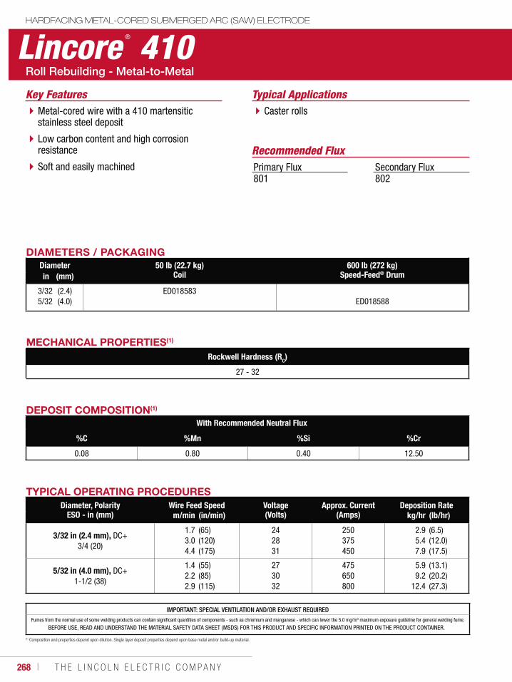
268 ı T H E L I N C O L N E L E C T R I C C O M P A N Y
Lincore ® 410HARDFACING METAL-CORED SUBMERGED ARC (SAW) ELECTRODE
Typical ApplicationsCaster rollsMetal-cored wire with a 410 martensitic
stainless steel deposit
Low carbon content and high corrosion resistance
Soft and easily machined
Key Features
DIAMETERS / PACKAGINGDiameter 50 lb (22.7 kg)
Coil600 lb (272 kg)
Speed-Feed® Drumin (mm)
3/325/32
(2.4)(4.0)
ED018583ED018588
Recommended FluxPrimary Flux801
Secondary Flux802
MECHANICAL PROPERTIES(1)
Rockwell Hardness (RC)
27 - 32
DEPOSIT COMPOSITION(1)
With Recommended Neutral Flux
%C %Mn %Si %Cr
0.08 0.80 0.40 12.50
(1) Composition and properties depend upon dilution. Single layer deposit properties depend upon base metal and/or build-up material.
TYPICAL OPERATING PROCEDURESDiameter, Polarity
ESO - in (mm)Wire Feed Speed Voltage
(Volts)Approx. Current
(Amps)Deposition Rate
m/min (in/min) kg/hr (lb/hr)
3/32 in (2.4 mm), DC+3/4 (20)
1.73.04.4
(65)(120)(175)
242831
250375450
2.95.47.9
(6.5)(12.0)(17.5)
5/32 in (4.0 mm), DC+1-1/2 (38)
1.42.22.9
(55)(85)(115)
273032
475650800
5.99.2
12.4
(13.1)(20.2)(27.3)
IMPORTANT: SPECIAL VENTILATION AND/OR EXHAUST REQUIREDFumes from the normal use of some welding products can contain significant quantities of components - such as chromium and manganese - which can lower the 5.0 mg/m3 maximum exposure guideline for general welding fume.
BEFORE USE, READ AND UNDERSTAND THE MATERIAL SAFETY DATA SHEET (MSDS) FOR THIS PRODUCT AND SPECIFIC INFORMATION PRINTED ON THE PRODUCT CONTAINER.
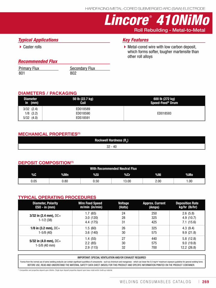
W E L D I N G C O N S U M A B L E S C A T A L O G ı 269
Lincore ® 410NiMoHARDFACING METAL-CORED SUBMERGED ARC (SAW) ELECTRODE
Typical ApplicationsCaster rolls Metal-cored wire with low carbon deposit,
which forms softer, tougher martensite than other roll alloys
Key Features
DIAMETERS / PACKAGINGDiameter 50 lb (22.7 kg)
Coil600 lb (272 kg)
Speed-Feed® Drumin (mm)
3/321/8
5/32
(2.4)(3.2)(4.0)
ED018589ED018590EDS18591
ED018593
Recommended FluxPrimary Flux801
Secondary Flux802
MECHANICAL PROPERTIES(1)
Rockwell Hardness (RC)
32 - 40
DEPOSIT COMPOSITION(1)
With Recommended Neutral Flux
%C %Mn %Si %Cr %Ni %Mo
0.05 0.80 0.50 13.00 2.00 1.00
(1) Composition and properties depend upon dilution. Single layer deposit properties depend upon base metal and/or build-up material.
TYPICAL OPERATING PROCEDURESDiameter, Polarity
ESO - in (mm)Wire Feed Speed Voltage
(Volts)Approx. Current
(Amps)Deposition Rate
m/min (in/min) kg/hr (lb/hr)
3/32 in (2.4 mm), DC+1-1/2 (38)
1.73.04.4
(65)(120)(175)
242831
250325425
2.64.97.1
(5.8)(10.7)(15.6)
1/8 in (3.2 mm), DC+1-5/8 (40)
1.53.6
(60)(140)
2630
325575
4.39.9
(9.4)(21.8)
5/32 in (4.0 mm), DC+1-5/8 (40 mm)
1.42.22.9
(55)(85)(115)
273032
440575700
5.89.0
12.2
(12.8)(19.8)(26.8)
IMPORTANT: SPECIAL VENTILATION AND/OR EXHAUST REQUIREDFumes from the normal use of some welding products can contain significant quantities of components - such as chromium and manganese - which can lower the 5.0 mg/m3 maximum exposure guideline for general welding fume.
BEFORE USE, READ AND UNDERSTAND THE MATERIAL SAFETY DATA SHEET (MSDS) FOR THIS PRODUCT AND SPECIFIC INFORMATION PRINTED ON THE PRODUCT CONTAINER.
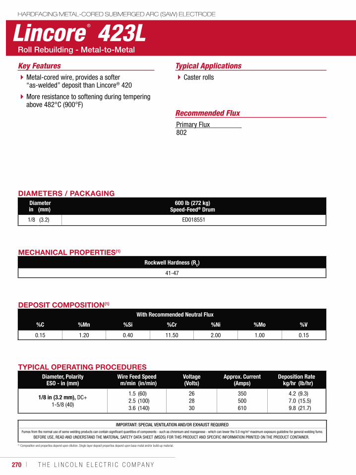
270 ı T H E L I N C O L N E L E C T R I C C O M P A N Y
Lincore ® 423LHARDFACING METAL-CORED SUBMERGED ARC (SAW) ELECTRODE
Typical ApplicationsCaster rollsMetal-cored wire, provides a softer
“as-welded” deposit than Lincore® 420
More resistance to softening during tempering above 482°C (900°F)
Key Features
DIAMETERS / PACKAGINGDiameter 600 lb (272 kg)
Speed-Feed® Drumin (mm)
1/8 (3.2) ED018551
Recommended FluxPrimary Flux802
MECHANICAL PROPERTIES(1)
Rockwell Hardness (RC)
41-47
DEPOSIT COMPOSITION(1)
With Recommended Neutral Flux
%C %Mn %Si %Cr %Ni %Mo %V
0.15 1.20 0.40 11.50 2.00 1.00 0.15
(1) Composition and properties depend upon dilution. Single layer deposit properties depend upon base metal and/or build-up material.
TYPICAL OPERATING PROCEDURESDiameter, Polarity
ESO - in (mm)Wire Feed Speed Voltage
(Volts)Approx. Current
(Amps)Deposition Rate
m/min (in/min) kg/hr (lb/hr)
1/8 in (3.2 mm), DC+1-5/8 (40)
1.52.53.6
(60)(100)(140)
262830
350500610
4.27.09.8
(9.3)(15.5)(21.7)
IMPORTANT: SPECIAL VENTILATION AND/OR EXHAUST REQUIREDFumes from the normal use of some welding products can contain significant quantities of components - such as chromium and manganese - which can lower the 5.0 mg/m3 maximum exposure guideline for general welding fume.
BEFORE USE, READ AND UNDERSTAND THE MATERIAL SAFETY DATA SHEET (MSDS) FOR THIS PRODUCT AND SPECIFIC INFORMATION PRINTED ON THE PRODUCT CONTAINER.
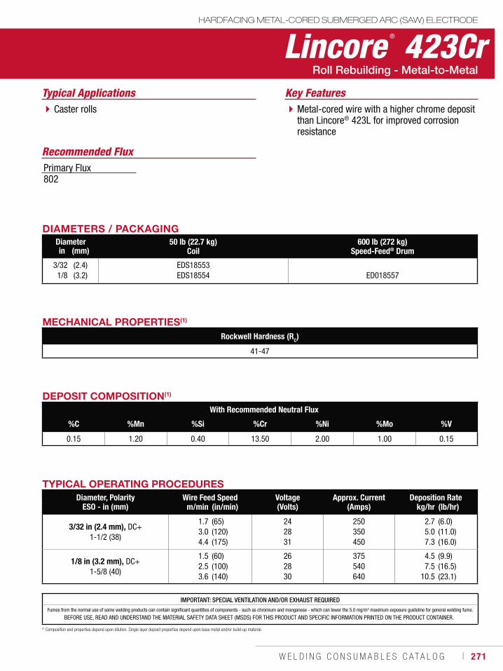
W E L D I N G C O N S U M A B L E S C A T A L O G ı 271
Lincore ® 423CrHARDFACING METAL-CORED SUBMERGED ARC (SAW) ELECTRODE
Typical ApplicationsCaster rolls Metal-cored wire with a higher chrome deposit
than Lincore® 423L for improved corrosion resistance
Recommended Flux
Key Features
DIAMETERS / PACKAGINGDiameter 50 lb (22.7 kg)
Coil600 lb (272 kg)
Speed-Feed® Drumin (mm)
3/321/8
(2.4)(3.2)
EDS18553EDS18554 ED018557
Primary Flux802
MECHANICAL PROPERTIES(1)
Rockwell Hardness (RC)
41-47
DEPOSIT COMPOSITION(1)
With Recommended Neutral Flux
%C %Mn %Si %Cr %Ni %Mo %V
0.15 1.20 0.40 13.50 2.00 1.00 0.15
(1) Composition and properties depend upon dilution. Single layer deposit properties depend upon base metal and/or build-up material.
TYPICAL OPERATING PROCEDURESDiameter, Polarity
ESO - in (mm)Wire Feed Speed Voltage
(Volts)Approx. Current
(Amps)Deposition Rate
m/min (in/min) kg/hr (lb/hr)
3/32 in (2.4 mm), DC+1-1/2 (38)
1.73.04.4
(65)(120)(175)
242831
250350450
2.75.07.3
(6.0)(11.0)(16.0)
1/8 in (3.2 mm), DC+1-5/8 (40)
1.52.53.6
(60)(100)(140)
262830
375540640
4.57.5
10.5
(9.9)(16.5)(23.1)
IMPORTANT: SPECIAL VENTILATION AND/OR EXHAUST REQUIREDFumes from the normal use of some welding products can contain significant quantities of components - such as chromium and manganese - which can lower the 5.0 mg/m3 maximum exposure guideline for general welding fume.
BEFORE USE, READ AND UNDERSTAND THE MATERIAL SAFETY DATA SHEET (MSDS) FOR THIS PRODUCT AND SPECIFIC INFORMATION PRINTED ON THE PRODUCT CONTAINER.
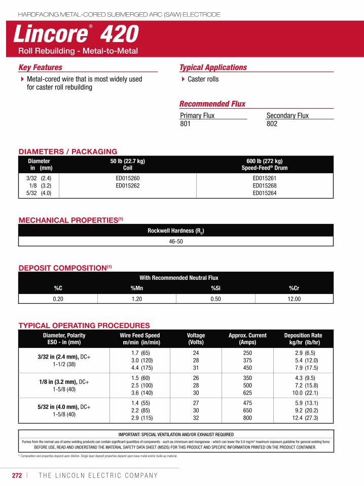
272 ı T H E L I N C O L N E L E C T R I C C O M P A N Y
Lincore ® 420HARDFACING METAL-CORED SUBMERGED ARC (SAW) ELECTRODE
Typical ApplicationsCaster rollsMetal-cored wire that is most widely used
for caster roll rebuilding
Key Features
DIAMETERS / PACKAGINGDiameter 50 lb (22.7 kg)
Coil600 lb (272 kg)
Speed-Feed® Drumin (mm)
3/321/8
5/32
(2.4)(3.2)(4.0)
ED015260ED015262
ED015261ED015268ED015264
Recommended FluxPrimary Flux801
Secondary Flux802
MECHANICAL PROPERTIES(1)
Rockwell Hardness (RC)
46-50
IMPORTANT: SPECIAL VENTILATION AND/OR EXHAUST REQUIREDFumes from the normal use of some welding products can contain significant quantities of components - such as chromium and manganese - which can lower the 5.0 mg/m3 maximum exposure guideline for general welding fume.
BEFORE USE, READ AND UNDERSTAND THE MATERIAL SAFETY DATA SHEET (MSDS) FOR THIS PRODUCT AND SPECIFIC INFORMATION PRINTED ON THE PRODUCT CONTAINER.
DEPOSIT COMPOSITION(1)
With Recommended Neutral Flux
%C %Mn %Si %Cr
0.20 1.20 0.50 12.00
(1) Composition and properties depend upon dilution. Single layer deposit properties depend upon base metal and/or build-up material.
TYPICAL OPERATING PROCEDURESDiameter, Polarity
ESO - in (mm)Wire Feed Speed Voltage
(Volts)Approx. Current
(Amps)Deposition Rate
m/min (in/min) kg/hr (lb/hr)
3/32 in (2.4 mm), DC+1-1/2 (38)
1.73.04.4
(65)(120)(175)
242831
250375450
2.95.47.9
(6.5)(12.0)(17.5)
1/8 in (3.2 mm), DC+1-5/8 (40)
1.52.53.6
(60)(100)(140)
262830
350500625
4.37.2
10.0
(9.5)(15.8)(22.1)
5/32 in (4.0 mm), DC+1-5/8 (40)
1.42.22.9
(55)(85)(115)
273032
475650800
5.99.2
12.4
(13.1)(20.2)(27.3)
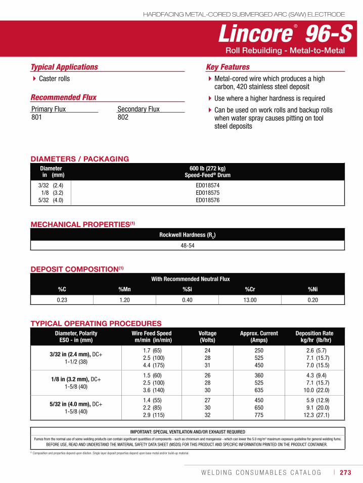
W E L D I N G C O N S U M A B L E S C A T A L O G ı 273
IMPORTANT: SPECIAL VENTILATION AND/OR EXHAUST REQUIREDFumes from the normal use of some welding products can contain significant quantities of components - such as chromium and manganese - which can lower the 5.0 mg/m3 maximum exposure guideline for general welding fume.
BEFORE USE, READ AND UNDERSTAND THE MATERIAL SAFETY DATA SHEET (MSDS) FOR THIS PRODUCT AND SPECIFIC INFORMATION PRINTED ON THE PRODUCT CONTAINER.
Lincore ® 96-SHARDFACING METAL-CORED SUBMERGED ARC (SAW) ELECTRODE
Typical ApplicationsCaster rolls Metal-cored wire which produces a high
carbon, 420 stainless steel deposit
Use where a higher hardness is required
Can be used on work rolls and backup rolls when water spray causes pitting on tool steel deposits
Key Features
DIAMETERS / PACKAGINGDiameter 600 lb (272 kg)
Speed-Feed® Drumin (mm)
3/321/8
5/32
(2.4)(3.2)(4.0)
ED018574ED018575ED018576
Recommended FluxPrimary Flux801
Secondary Flux802
MECHANICAL PROPERTIES(1)
Rockwell Hardness (RC)
48-54
DEPOSIT COMPOSITION(1)
With Recommended Neutral Flux
%C %Mn %Si %Cr %Ni
0.23 1.20 0.40 13.00 0.20
(1) Composition and properties depend upon dilution. Single layer deposit properties depend upon base metal and/or build-up material.
TYPICAL OPERATING PROCEDURESDiameter, Polarity
ESO - in (mm)Wire Feed Speed Voltage
(Volts)Approx. Current
(Amps)Deposition Rate
m/min (in/min) kg/hr (lb/hr)
3/32 in (2.4 mm), DC+1-1/2 (38)
1.72.54.4
(65)(100)(175)
242831
250525450
2.67.17.0
(5.7)(15.7)(15.5)
1/8 in (3.2 mm), DC+1-5/8 (40)
1.52.53.6
(60)(100)(140)
262830
360525635
4.37.1
10.0
(9.4)(15.7)(22.0)
5/32 in (4.0 mm), DC+1-5/8 (40)
1.42.22.9
(55)(85)(115)
273032
450650775
5.99.1
12.3
(12.9)(20.0)(27.1)
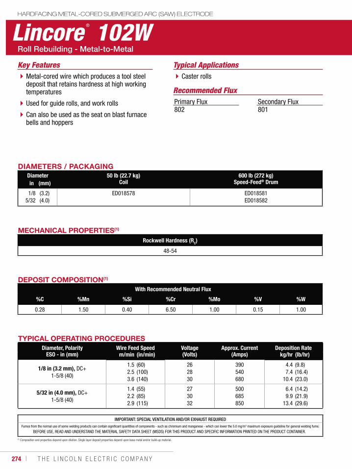
274 ı T H E L I N C O L N E L E C T R I C C O M P A N Y
Lincore ® 102WHARDFACING METAL-CORED SUBMERGED ARC (SAW) ELECTRODE
Typical ApplicationsCaster rollsMetal-cored wire which produces a tool steel
deposit that retains hardness at high working temperatures
Used for guide rolls, and work rolls
Can also be used as the seat on blast furnace bells and hoppers
Key Features
DIAMETERS / PACKAGINGDiameter 50 lb (22.7 kg)
Coil600 lb (272 kg)
Speed-Feed® Drumin (mm)
1/85/32
(3.2)(4.0)
ED018578 ED018581ED018582
Recommended FluxPrimary Flux802
Secondary Flux801
MECHANICAL PROPERTIES(1)
Rockwell Hardness (RC)
48-54
IMPORTANT: SPECIAL VENTILATION AND/OR EXHAUST REQUIREDFumes from the normal use of some welding products can contain significant quantities of components - such as chromium and manganese - which can lower the 5.0 mg/m3 maximum exposure guideline for general welding fume.
BEFORE USE, READ AND UNDERSTAND THE MATERIAL SAFETY DATA SHEET (MSDS) FOR THIS PRODUCT AND SPECIFIC INFORMATION PRINTED ON THE PRODUCT CONTAINER.
DEPOSIT COMPOSITION(1)
With Recommended Neutral Flux
%C %Mn %Si %Cr %Mo %V %W
0.28 1.50 0.40 6.50 1.00 0.15 1.00
(1) Composition and properties depend upon dilution. Single layer deposit properties depend upon base metal and/or build-up material.
TYPICAL OPERATING PROCEDURESDiameter, Polarity
ESO - in (mm)Wire Feed Speed Voltage
(Volts)Approx. Current
(Amps)Deposition Rate
m/min (in/min) kg/hr (lb/hr)
1/8 in (3.2 mm), DC+1-5/8 (40)
1.52.53.6
(60)(100)(140)
262830
390540680
4.47.4
10.4
(9.8)(16.4)(23.0)
5/32 in (4.0 mm), DC+1-5/8 (40)
1.42.22.9
(55)(85)(115)
273032
500685850
6.49.9
13.4
(14.2)(21.9)(29.6)
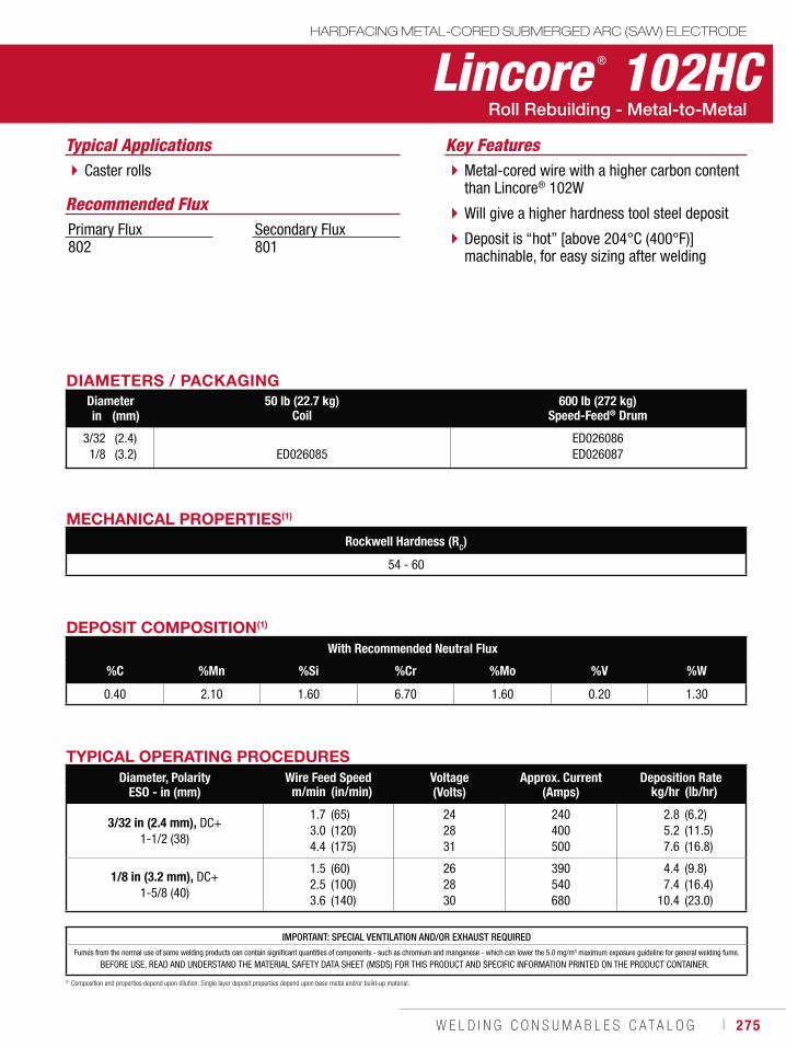
W E L D I N G C O N S U M A B L E S C A T A L O G ı 275
IMPORTANT: SPECIAL VENTILATION AND/OR EXHAUST REQUIREDFumes from the normal use of some welding products can contain significant quantities of components - such as chromium and manganese - which can lower the 5.0 mg/m3 maximum exposure guideline for general welding fume.
BEFORE USE, READ AND UNDERSTAND THE MATERIAL SAFETY DATA SHEET (MSDS) FOR THIS PRODUCT AND SPECIFIC INFORMATION PRINTED ON THE PRODUCT CONTAINER.
Lincore ® 102HCHARDFACING METAL-CORED SUBMERGED ARC (SAW) ELECTRODE
Typical ApplicationsCaster rolls Metal-cored wire with a higher carbon content
than Lincore® 102W
Will give a higher hardness tool steel deposit
Deposit is “hot” [above 204°C (400°F)] machinable, for easy sizing after welding
Key Features
DIAMETERS / PACKAGINGDiameter 50 lb (22.7 kg)
Coil600 lb (272 kg)
Speed-Feed® Drumin (mm)
3/321/8
(2.4)(3.2) ED026085
ED026086ED026087
Recommended FluxPrimary Flux802
Secondary Flux801
MECHANICAL PROPERTIES(1)
Rockwell Hardness (RC)
54 - 60
DEPOSIT COMPOSITION(1)
With Recommended Neutral Flux
%C %Mn %Si %Cr %Mo %V %W
0.40 2.10 1.60 6.70 1.60 0.20 1.30
(1) Composition and properties depend upon dilution. Single layer deposit properties depend upon base metal and/or build-up material.
TYPICAL OPERATING PROCEDURESDiameter, Polarity
ESO - in (mm)Wire Feed Speed Voltage
(Volts)Approx. Current
(Amps)Deposition Rate
m/min (in/min) kg/hr (lb/hr)
3/32 in (2.4 mm), DC+1-1/2 (38)
1.73.04.4
(65)(120)(175)
242831
240400500
2.85.27.6
(6.2)(11.5)(16.8)
1/8 in (3.2 mm), DC+1-5/8 (40)
1.52.53.6
(60)(100)(140)
262830
390540680
4.47.4
10.4
(9.8)(16.4)(23.0)
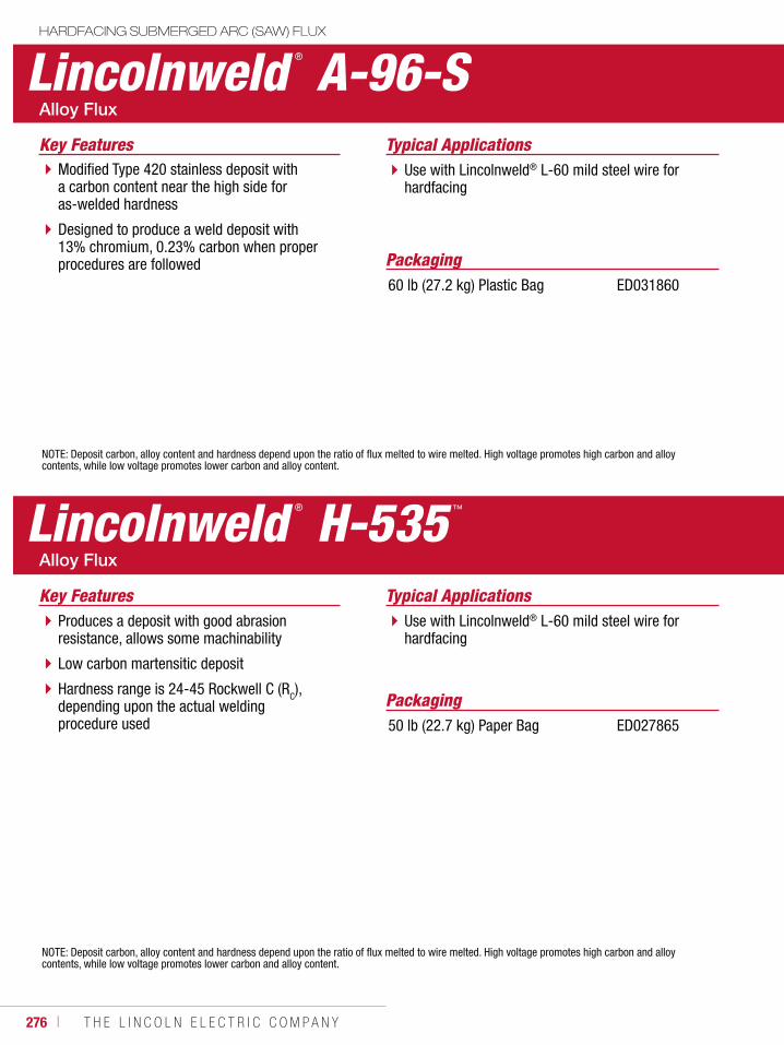
276 ı T H E L I N C O L N E L E C T R I C C O M P A N Y
Packaging
Lincolnweld ® A-96-SHARDFACING SUBMERGED ARC (SAW) FLUX
Typical ApplicationsUse with Lincolnweld® L-60 mild steel wire for hardfacing
Modified Type 420 stainless deposit with a carbon content near the high side for as-welded hardness
Designed to produce a weld deposit with 13% chromium, 0.23% carbon when proper procedures are followed
Key Features
NOTE: Deposit carbon, alloy content and hardness depend upon the ratio of flux melted to wire melted. High voltage promotes high carbon and alloy contents, while low voltage promotes lower carbon and alloy content.
60 lb (27.2 kg) Plastic Bag ED031860
Lincolnweld ® H-535 ™
Typical ApplicationsUse with Lincolnweld® L-60 mild steel wire for hardfacing
Produces a deposit with good abrasion resistance, allows some machinability
Low carbon martensitic deposit
Hardness range is 24-45 Rockwell C (RC), depending upon the actual welding procedure used
Key Features
NOTE: Deposit carbon, alloy content and hardness depend upon the ratio of flux melted to wire melted. High voltage promotes high carbon and alloy contents, while low voltage promotes lower carbon and alloy content.
Packaging50 lb (22.7 kg) Paper Bag ED027865

W E L D I N G C O N S U M A B L E S C A T A L O G ı 277
Lincolnweld ® H-560 ™
HARDFACING SUBMERGED ARC (SAW) FLUX
Typical ApplicationsUse with Lincolnweld® L-60 mild steel wire for hardfacing
High alloy flux depositing primary carbides in a martensitic matrix
Excellent material for severe abrasion applications
Resistance to abrasion is 50 to 60 times that of plain carbon steel
Key Features
NOTE: Deposit carbon, alloy content and hardness depend upon the ratio of flux melted to wire melted. High voltage promotes high carbon and alloy contents, while low voltage promotes lower carbon and alloy content.
Packaging
Lincolnweld ® 801®
Typical ApplicationsHardfacing
Use with Lincore® 20, 30-S, 35-S, 40-S, 42-S, 4130, 8620, 410, 410NiMo, 420 and 96S
Provides smooth beads and excellent slag removal
Fast-freezing
Key Features
NOTE: Deposit carbon, alloy content and hardness depend upon the ratio of flux melted to wire melted. High voltage promotes high carbon and alloy contents, while low voltage promotes lower carbon and alloy content.
Packaging
100 lb (45.4 kg) Paper Bag ED010345
50 lb (22.7 kg) Paper Bag550 lb (249 kg) Drum3000 lb (1361 kg) Bulk Bag
ED019588ED023403EDS30786
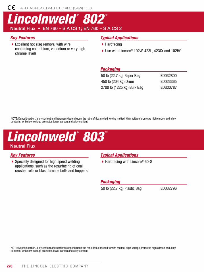
278 ı T H E L I N C O L N E L E C T R I C C O M P A N Y
Typical ApplicationsHardfacing
Use with Lincore® 102W, 423L, 423Cr and 102HC
Excellent hot slag removal with wire containing columbium, vanadium or very high chrome levels
Key Features
Lincolnweld ® 802 ®
HARDFACING SUBMERGED ARC (SAW) FLUX
NOTE: Deposit carbon, alloy content and hardness depend upon the ratio of flux melted to wire melted. High voltage promotes high carbon and alloy contents, while low voltage promotes lower carbon and alloy content.
Packaging
Lincolnweld ® 803 ™
Typical ApplicationsHardfacing with Lincore® 60-SSpecially designed for high speed welding
applications, such as the resurfacing of coal crusher rolls or blast furnace bells and hoppers
Key Features
NOTE: Deposit carbon, alloy content and hardness depend upon the ratio of flux melted to wire melted. High voltage promotes high carbon and alloy contents, while low voltage promotes lower carbon and alloy content.
Packaging
50 lb (22.7 kg) Paper Bag450 lb (204 kg) Drum2700 lb (1225 kg) Bulk Bag
ED032800 ED023365EDS30787
50 lb (22.7 kg) Plastic Bag ED032796
W E L D I N G C O N S U M A B L E S C A T A L O G ı 279
CONSUMABLES
AluminumMIG WireSuperGlaze® 4043 ........................................280SuperGlaze® 4047 ........................................281SuperGlaze® 5183 ........................................282SuperGlaze® 5356 ........................................283SuperGlaze® 5554 ........................................284SuperGlaze® 5556 ........................................285
TIG Cut LengthSuperGlaze® 4043 ........................................286SuperGlaze® 5356 ........................................287
Cast IronStick ElectrodeSoftweld® 55Ni .............................................288Softweld® 99Ni .............................................289Ferroweld™ ..................................................290
ALUMINUM & CAST IRON
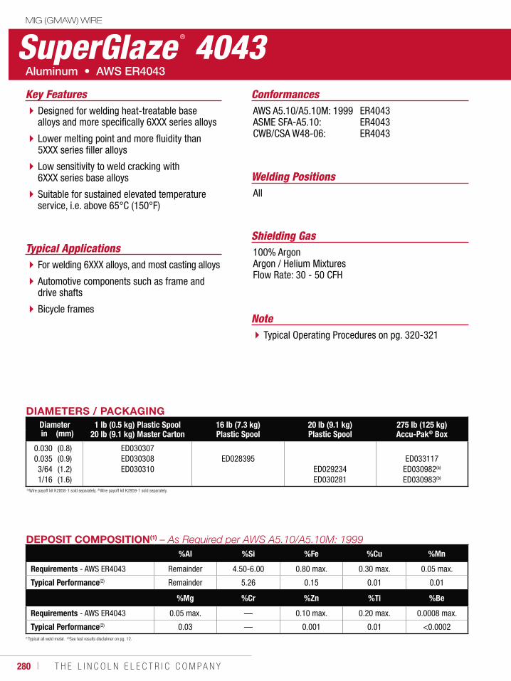
280 ı T H E L I N C O L N E L E C T R I C C O M P A N Y
SuperGlaze ® 4043MIG (GMAW) WIRE
Welding Positions
Typical Applications
All
For welding 6XXX alloys, and most casting alloys
Automotive components such as frame and drive shafts
Bicycle frames
Designed for welding heat-treatable base alloys and more specifically 6XXX series alloys
Lower melting point and more fluidity than 5XXX series filler alloys
Low sensitivity to weld cracking with 6XXX series base alloys
Suitable for sustained elevated temperature service, i.e. above 65°C (150°F)
Conformances
Shielding Gas100% ArgonArgon / Helium MixturesFlow Rate: 30 - 50 CFH
Key FeaturesAWS A5.10/A5.10M: 1999ASME SFA-A5.10:CWB/CSA W48-06:
ER4043ER4043ER4043
DIAMETERS / PACKAGINGDiameter 1 lb (0.5 kg) Plastic Spool
20 lb (9.1 kg) Master Carton16 lb (7.3 kg)Plastic Spool
20 lb (9.1 kg)Plastic Spool
275 lb (125 kg)Accu-Pak® Boxin (mm)
0.0300.0353/641/16
(0.8)(0.9)(1.2)(1.6)
ED030307 ED030308 ED030310
ED028395 ED029234 ED030281
ED033117 ED030982(a) ED030983(b)
(a)Wire payoff kit K2858-1 sold separately. (b)Wire payoff kit K2859-1 sold separately.
(1)Typical all weld metal. (2)See test results disclaimer on pg. 12.
DEPOSIT COMPOSITION(1)
%Al %Si %Fe %Cu %Mn
Requirements - AWS ER4043 Remainder 4.50-6.00 0.80 max. 0.30 max. 0.05 max.
Typical Performance(2) Remainder 5.26 0.15 0.01 0.01
%Mg %Cr %Zn %Ti %Be
Requirements - AWS ER4043 0.05 max. — 0.10 max. 0.20 max. 0.0008 max.
Typical Performance(2) 0.03 — 0.001 0.01 <0.0002
NoteTypical Operating Procedures on pg. 320-321
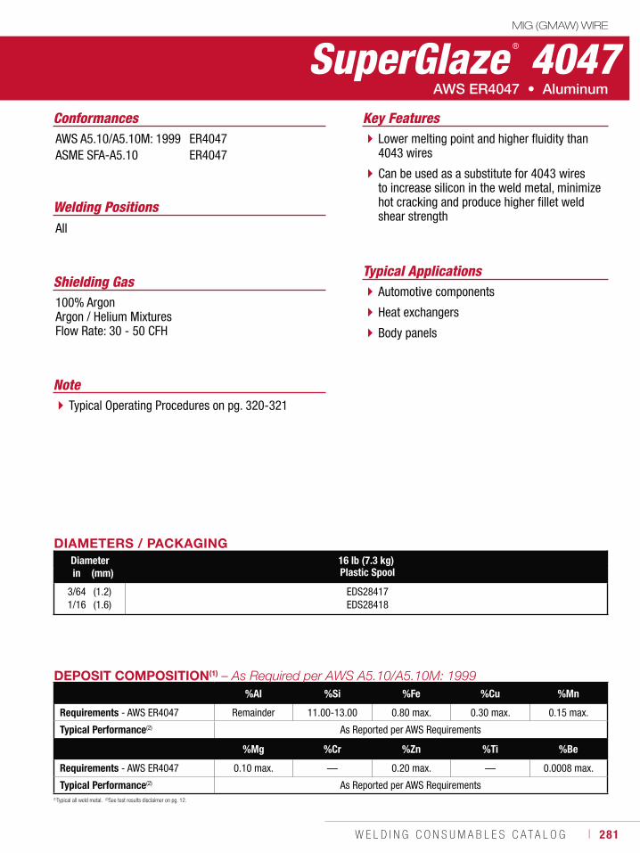
W E L D I N G C O N S U M A B L E S C A T A L O G ı 281
SuperGlaze ® 4047MIG (GMAW) WIRE
Welding Positions
Typical Applications
All
Automotive components
Heat exchangers
Body panels
Lower melting point and higher fluidity than 4043 wires
Can be used as a substitute for 4043 wires to increase silicon in the weld metal, minimize hot cracking and produce higher fillet weld shear strength
Conformances
Shielding Gas100% ArgonArgon / Helium MixturesFlow Rate: 30 - 50 CFH
Key FeaturesAWS A5.10/A5.10M: 1999ASME SFA-A5.10
ER4047ER4047
DIAMETERS / PACKAGINGDiameter 16 lb (7.3 kg)
Plastic Spoolin (mm)
3/641/16
(1.2)(1.6)
EDS28417 EDS28418
(1)Typical all weld metal. (2)See test results disclaimer on pg. 12.
DEPOSIT COMPOSITION(1)
%Al %Si %Fe %Cu %Mn
Requirements - AWS ER4047 Remainder 11.00-13.00 0.80 max. 0.30 max. 0.15 max.
Typical Performance(2) As Reported per AWS Requirements
%Mg %Cr %Zn %Ti %Be
Requirements - AWS ER4047 0.10 max. — 0.20 max. — 0.0008 max.
Typical Performance(2) As Reported per AWS Requirements
NoteTypical Operating Procedures on pg. 320-321
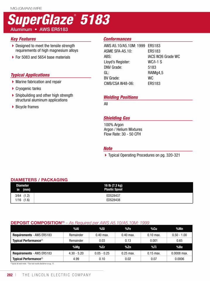
282 ı T H E L I N C O L N E L E C T R I C C O M P A N Y
SuperGlaze ® 5183MIG (GMAW) WIRE
Welding Positions
Typical Applications
All
Marine fabrication and repair
Cryogenic tanks
Shipbuilding and other high strength structural aluminum applications
Bicycle frames
Designed to meet the tensile strength requirements of high magnesium alloys
For 5083 and 5654 base materials
Conformances
Shielding Gas100% ArgonArgon / Helium MixturesFlow Rate: 30 - 50 CFH
Key FeaturesAWS A5.10/A5.10M: 1999ASME SFA-A5.10:ABS:Lloyd’s Register:DNV Grade:GL:BV Grade:CWB/CSA W48-06:
ER5183ER5183IACS W26 Grade WCWC/I-1 S5183RAIMg4,5WCER5183
DIAMETERS / PACKAGINGDiameter 16 lb (7.3 kg)
Plastic Spoolin (mm)
3/641/16
(1.2)(1.6)
EDS28437 EDS28438
(1)Typical all weld metal. (2)See test results disclaimer on pg. 12.
DEPOSIT COMPOSITION(1)
%Al %Si %Fe %Cu %Mn
Requirements - AWS ER5183 Remainder 0.40 max. 0.40 max. 0.10 max. 0.50 - 1.00
Typical Performance(2) Remainder 0.03 0.13 0.001 0.65
%Mg %Cr %Zn %Ti %Be
Requirements - AWS ER5183 4.30 - 5.20 0.05 - 0.25 0.25 max. 0.15 max. 0.0008 max.
Typical Performance(2) 4.99 0.10 0.02 0.07 0.0006
NoteTypical Operating Procedures on pg. 320-321
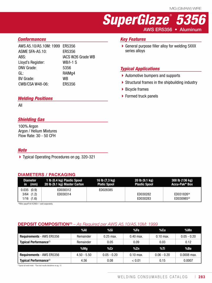
W E L D I N G C O N S U M A B L E S C A T A L O G ı 283
SuperGlaze ® 5356MIG (GMAW) WIRE
Welding Positions
Typical Applications
All
Automotive bumpers and supports
Structural frames in the shipbuilding industry
Bicycle frames
Formed truck panels
General purpose filler alloy for welding 5XXX series alloys
Conformances
Shielding Gas100% ArgonArgon / Helium MixturesFlow Rate: 30 - 50 CFH
Key FeaturesAWS A5.10/A5.10M: 1999ASME SFA-A5.10:ABS:Lloyd’s Register:DNV Grade:GL:BV Grade:CWB/CSA W48-06:
ER5356ER5356IACS W26 Grade WBWB/I-1 S5356RAIMg4WBER5356
DIAMETERS / PACKAGINGDiameter 1 lb (0.4 kg) Plastic Spool
20 lb (9.1 kg) Master Carton16 lb (7.3 kg)Platic Spool
20 lb (9.1 kg)Plastic Spool
300 lb (136 kg)Accu-Pak® Boxin (mm)
0.0353/641/16
(0.9)(1.2)(1.6)
ED030312 ED030314
ED028385 ED030282 ED030283
ED031826(a) ED030985(a)
(a)Wire payoff kit K2860-1 sold separately.
(1)Typical all weld metal. (2)See test results disclaimer on pg. 12.
DEPOSIT COMPOSITION(1)
%Al %Si %Fe %Cu %Mn
Requirements - AWS ER5356 Remainder 0.25 max. 0.40 max. 0.10 max. 0.05 - 0.20
Typical Performance(2) Remainder 0.05 0.09 0.03 0.12
%Mg %Cr %Zn %Ti %Be
Requirements - AWS ER5356 4.50 - 5.50 0.05 - 0.20 0.10 max. 0.06 - 0.20 0.0008 max.
Typical Performance(2) 4.56 0.08 < 0.01 0.15 0.0007
NoteTypical Operating Procedures on pg. 320-321
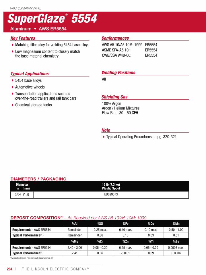
284 ı T H E L I N C O L N E L E C T R I C C O M P A N Y
SuperGlaze ® 5554MIG (GMAW) WIRE
Welding PositionsTypical ApplicationsAll5454 base alloys
Automotive wheels
Transportation applications such as over-the-road trailers and rail tank cars
Chemical storage tanks
Matching filler alloy for welding 5454 base alloys
Low magnesium content to closely match the base material chemistry
Conformances
Shielding Gas100% ArgonArgon / Helium MixturesFlow Rate: 30 - 50 CFH
Key FeaturesAWS A5.10/A5.10M: 1999ASME SFA-A5.10:CWB/CSA W48-06:
ER5554ER5554ER5554
DIAMETERS / PACKAGINGDiameter 16 lb (7.3 kg)
Plastic Spoolin (mm)
3/64 (1.2) ED029573
(1)Typical all weld metal. (2)See test results disclaimer on pg. 12.
DEPOSIT COMPOSITION(1)
%Al %Si %Fe %Cu %Mn
Requirements - AWS ER5554 Remainder 0.25 max. 0.40 max. 0.10 max. 0.50 - 1.00
Typical Performance(2) Remainder 0.06 0.13 0.03 0.51
%Mg %Cr %Zn %Ti %Be
Requirements - AWS ER5554 2.40 - 3.00 0.05 - 0.20 0.25 max. 0.06 - 0.20 0.0008 max.
Typical Performance(2) 2.41 0.06 < 0.01 0.09 0.0006
NoteTypical Operating Procedures on pg. 320-321
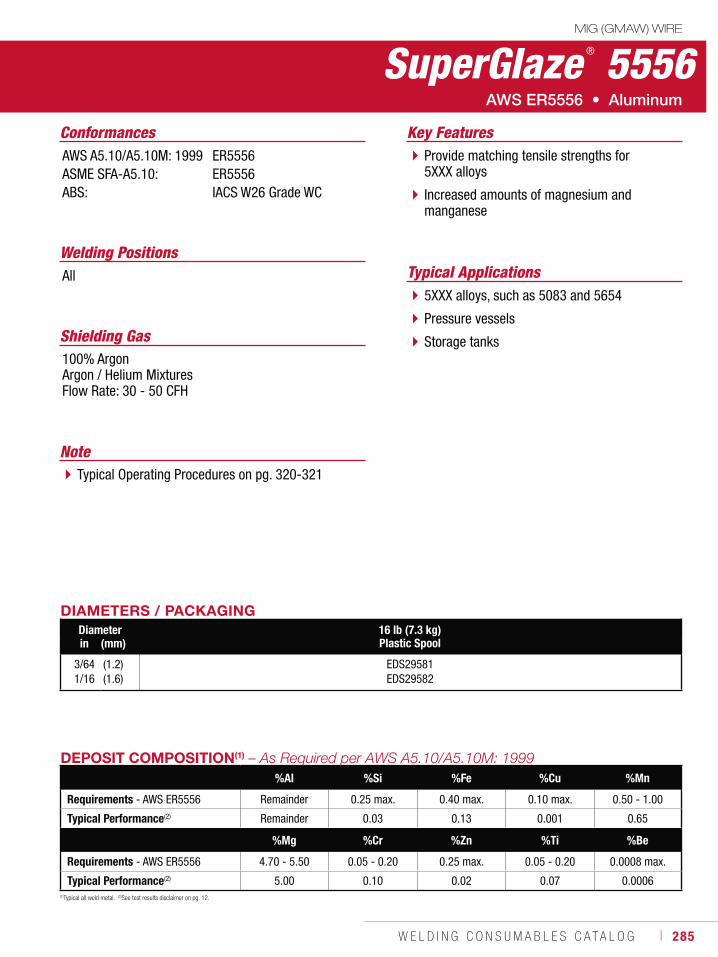
W E L D I N G C O N S U M A B L E S C A T A L O G ı 285
SuperGlaze ® 5556MIG (GMAW) WIRE
Welding PositionsTypical ApplicationsAll
5XXX alloys, such as 5083 and 5654
Pressure vessels
Storage tanks
Provide matching tensile strengths for 5XXX alloys
Increased amounts of magnesium and manganese
Conformances
Shielding Gas100% Argon Argon / Helium Mixtures Flow Rate: 30 - 50 CFH
Key FeaturesAWS A5.10/A5.10M: 1999ASME SFA-A5.10:ABS:
ER5556ER5556IACS W26 Grade WC
DIAMETERS / PACKAGINGDiameter 16 lb (7.3 kg)
Plastic Spoolin (mm)
3/641/16
(1.2)(1.6)
EDS29581EDS29582
(1)Typical all weld metal. (2)See test results disclaimer on pg. 12.
DEPOSIT COMPOSITION(1)
%Al %Si %Fe %Cu %Mn
Requirements - AWS ER5556 Remainder 0.25 max. 0.40 max. 0.10 max. 0.50 - 1.00
Typical Performance(2) Remainder 0.03 0.13 0.001 0.65
%Mg %Cr %Zn %Ti %Be
Requirements - AWS ER5556 4.70 - 5.50 0.05 - 0.20 0.25 max. 0.05 - 0.20 0.0008 max.
Typical Performance(2) 5.00 0.10 0.02 0.07 0.0006
NoteTypical Operating Procedures on pg. 320-321
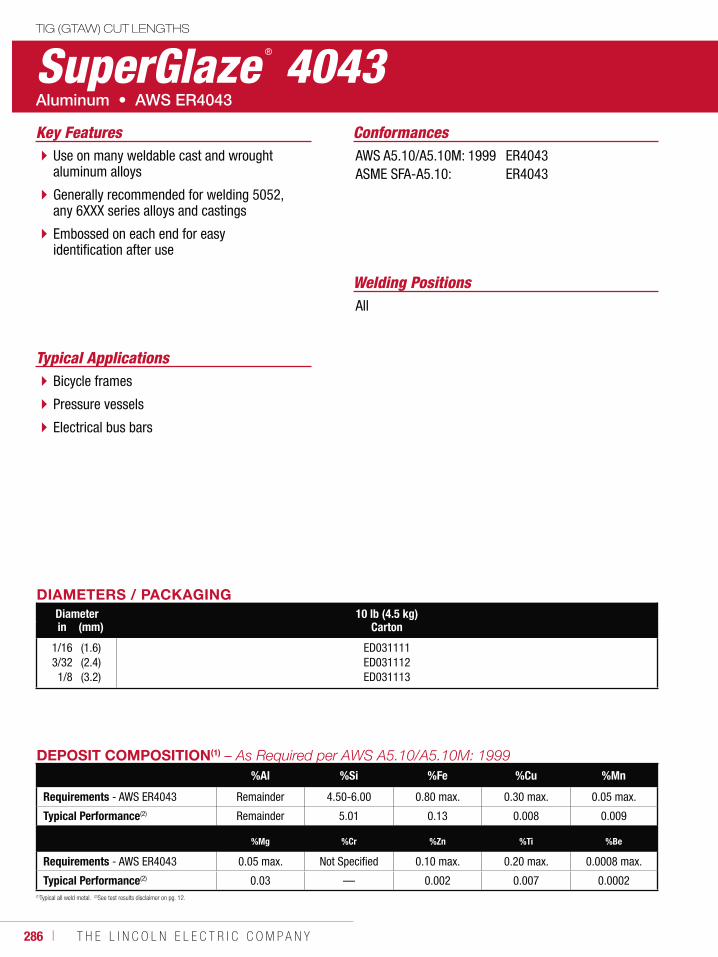
286 ı T H E L I N C O L N E L E C T R I C C O M P A N Y
Typical ApplicationsBicycle frames
Pressure vessels
Electrical bus bars
SuperGlaze ® 4043TIG (GTAW) CUT LENGTHS
Welding PositionsAll
Use on many weldable cast and wrought aluminum alloys
Generally recommended for welding 5052, any 6XXX series alloys and castings
Embossed on each end for easy identification after use
ConformancesKey FeaturesAWS A5.10/A5.10M: 1999ASME SFA-A5.10:
ER4043ER4043
DIAMETERS / PACKAGINGDiameter 10 lb (4.5 kg)
Cartonin (mm)
1/163/321/8
(1.6)(2.4)(3.2)
ED031111ED031112ED031113
(1)Typical all weld metal. (2)See test results disclaimer on pg. 12.
DEPOSIT COMPOSITION(1)
%Al %Si %Fe %Cu %Mn
Requirements - AWS ER4043 Remainder 4.50-6.00 0.80 max. 0.30 max. 0.05 max.
Typical Performance(2) Remainder 5.01 0.13 0.008 0.009
%Mg %Cr %Zn %Ti %Be
Requirements - AWS ER4043 0.05 max. Not Specified 0.10 max. 0.20 max. 0.0008 max.
Typical Performance(2) 0.03 — 0.002 0.007 0.0002
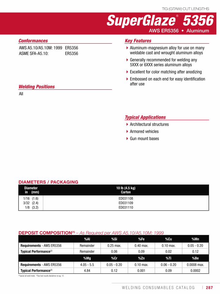
W E L D I N G C O N S U M A B L E S C A T A L O G ı 287
Typical ApplicationsArchitectural structures
Armored vehicles
Gun mount bases
SuperGlaze ® 5356TIG (GTAW) CUT LENGTHS
Welding PositionsAll
Aluminum-magnesium alloy for use on many weldable cast and wrought aluminum alloys
Generally recommended for welding any 5XXX or 6XXX series aluminum alloys
Excellent for color matching after anodizing
Embossed on each end for easy identification after use
Conformances Key FeaturesAWS A5.10/A5.10M: 1999ASME SFA-A5.10:
ER5356ER5356
DIAMETERS / PACKAGINGDiameter 10 lb (4.5 kg)
Cartonin (mm)
1/163/321/8
(1.6)(2.4)(3.2)
ED031108ED031109ED031110
(1)Typical all weld metal. (2)See test results disclaimer on pg. 12.
DEPOSIT COMPOSITION(1)
%Al %Si %Fe %Cu %Mn
Requirements - AWS ER5356 Remainder 0.25 max. 0.40 max. 0.10 max. 0.05 - 0.20
Typical Performance(2) Remainder 0.06 0.09 0.02 0.12
%Mg %Cr %Zn %Ti %Be
Requirements - AWS ER5356 4.05 - 5.5 0.05 - 0.20 0.10 max. 0.06 - 0.20 0.0008 max.
Typical Performance(2) 4.84 0.12 0.001 0.09 0.0002
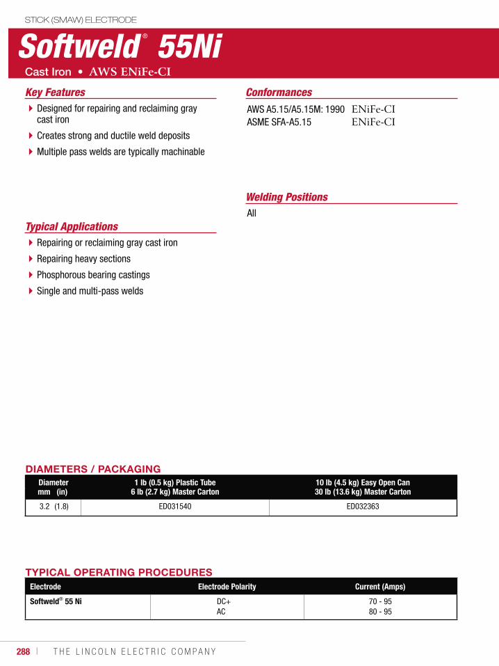
288 ı T H E L I N C O L N E L E C T R I C C O M P A N Y
Softweld ® 55NiSTICK (SMAW) ELECTRODE
Welding Positions
Typical ApplicationsAll
Repairing or reclaiming gray cast iron
Repairing heavy sections
Phosphorous bearing castings
Single and multi-pass welds
Designed for repairing and reclaiming gray cast iron
Creates strong and ductile weld deposits
Multiple pass welds are typically machinable
ConformancesKey FeaturesAWS A5.15/A5.15M: 1990ASME SFA-A5.15
DIAMETERS / PACKAGINGDiameter 1 lb (0.5 kg) Plastic Tube
6 lb (2.7 kg) Master Carton10 lb (4.5 kg) Easy Open Can30 lb (13.6 kg) Master Cartonmm (in)
3.2 (1.8) ED031540 ED032363
TYPICAL OPERATING PROCEDURESElectrode Electrode Polarity Current (Amps)
Softweld® 55 Ni DC+AC
70 - 9580 - 95
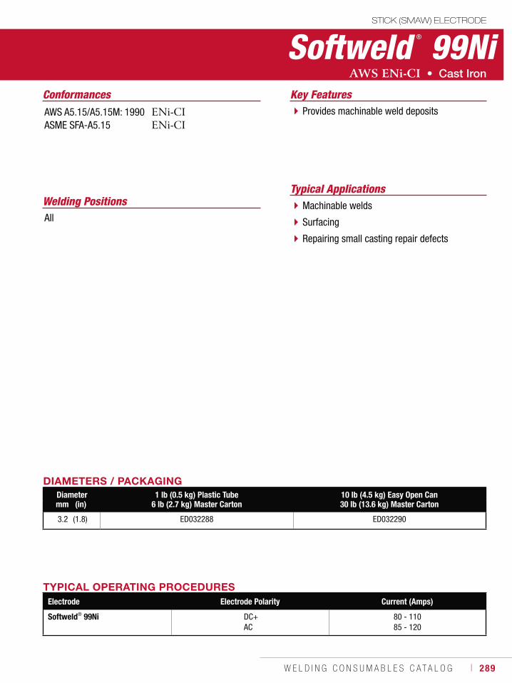
W E L D I N G C O N S U M A B L E S C A T A L O G ı 289
Softweld ® 99NiSTICK (SMAW) ELECTRODE
Welding PositionsTypical Applications
AllMachinable welds
Surfacing
Repairing small casting repair defects
Provides machinable weld deposits
Conformances Key FeaturesAWS A5.15/A5.15M: 1990ASME SFA-A5.15
DIAMETERS / PACKAGINGDiameter 1 lb (0.5 kg) Plastic Tube
6 lb (2.7 kg) Master Carton10 lb (4.5 kg) Easy Open Can30 lb (13.6 kg) Master Cartonmm (in)
3.2 (1.8) ED032288 ED032290
TYPICAL OPERATING PROCEDURESElectrode Electrode Polarity Current (Amps)
Softweld® 99Ni DC+AC
80 - 11085 - 120
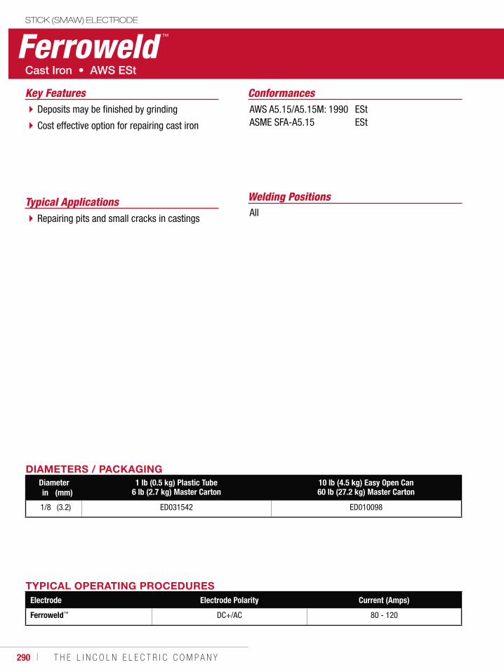
290 ı T H E L I N C O L N E L E C T R I C C O M P A N Y
Ferroweld ™
STICK (SMAW) ELECTRODE
Welding PositionsTypical ApplicationsAllRepairing pits and small cracks in castings
Deposits may be finished by grinding
Cost effective option for repairing cast iron
ConformancesKey FeaturesAWS A5.15/A5.15M: 1990ASME SFA-A5.15
EStESt
DIAMETERS / PACKAGINGDiameter 1 lb (0.5 kg) Plastic Tube
6 lb (2.7 kg) Master Carton10 lb (4.5 kg) Easy Open Can60 lb (27.2 kg) Master Cartonin (mm)
1/8 (3.2) ED031542 ED010098
TYPICAL OPERATING PROCEDURESElectrode Electrode Polarity Current (Amps)
Ferroweld™ DC+/AC 80 - 120
W E L D I N G C O N S U M A B L E S C A T A L O G ı 291
PACKAGINGCONSUMABLES
OptionsTubes, Cans & Cartons ...................................292Reels & Stem .................................................294Spools ............................................................296Coils, Boxes & Bags .......................................298Drums & Pails ................................................300
Storage and HandlingStick Electrode ...............................................302Metal-Cored & Flux-Cored Wire ......................304Submerged Arc Flux & Wire ............................305
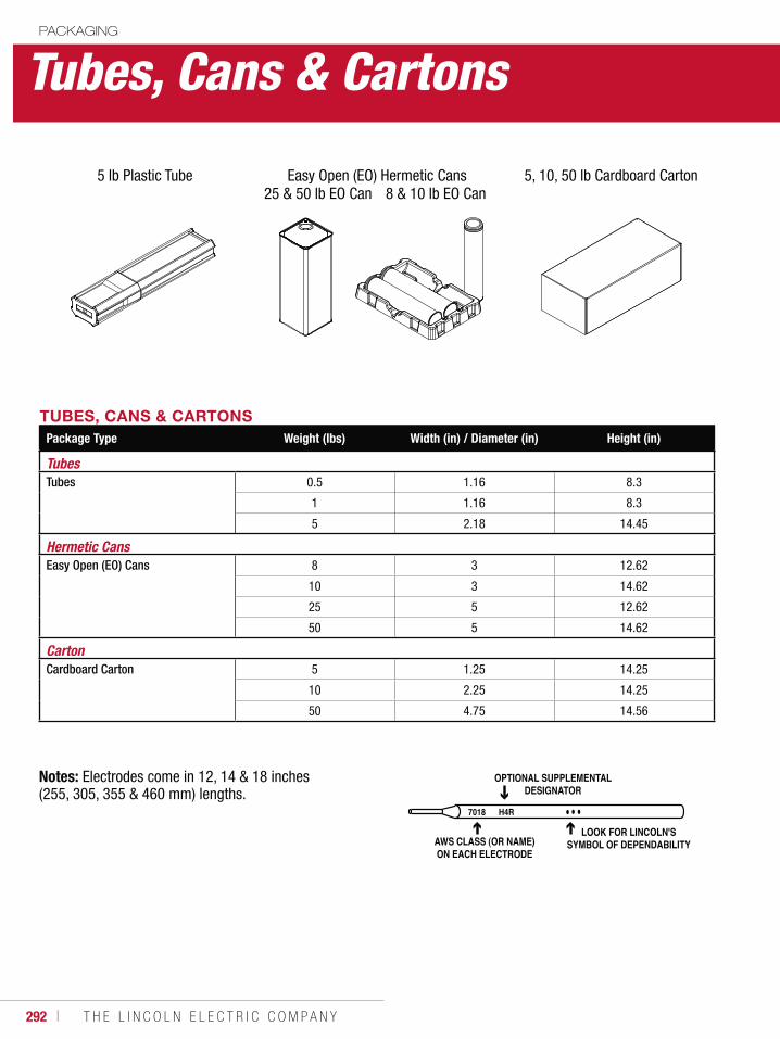
292 ı T H E L I N C O L N E L E C T R I C C O M P A N Y
Tubes, Cans & CartonsPACKAGING
TUBES, CANS & CARTONSPackage Type Weight (lbs) Width (in) / Diameter (in) Height (in)
TubesTubes 0.5 1.16 8.3
1 1.16 8.3
5 2.18 14.45
Hermetic CansEasy Open (EO) Cans 8 3 12.62
10 3 14.62
25 5 12.62
50 5 14.62
CartonCardboard Carton 5 1.25 14.25
10 2.25 14.25
50 4.75 14.56
Notes: Electrodes come in 12, 14 & 18 inches (255, 305, 355 & 460 mm) lengths.
7018 H4R
OPTIONAL SUPPLEMENTALDESIGNATOR
AWS CLASS (OR NAME)ON EACH ELECTRODE
LOOK FOR LINCOLN'SSYMBOL OF DEPENDABILITY
5 lb Plastic Tube Easy Open (EO) Hermetic Cans 5, 10, 50 lb Cardboard Carton25 & 50 lb EO Can 8 & 10 lb EO Can
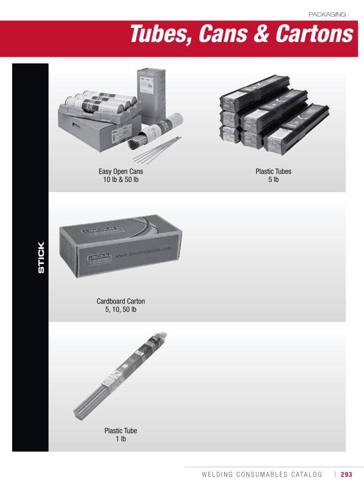
W E L D I N G C O N S U M A B L E S C A T A L O G ı 293
ST
ICK
Easy Open Cans10 lb & 50 lb
Plastic Tubes5 lb
Cardboard Carton5, 10, 50 lb
Plastic Tube1 lb
Tubes, Cans & CartonsPACKAGING
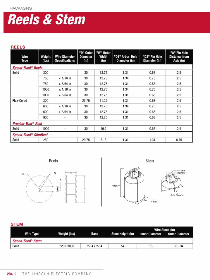
294 ı T H E L I N C O L N E L E C T R I C C O M P A N Y
Reels & StemPACKAGING
REELS
Wire Type
Weight (lbs)
Wire Diameter Specifications
"D" Outer Diameter
(in)
"W" Outer Width
(in)"D1" Arbor Hole
Diameter (in)"D2" Pin Hole Diameter (in)
"A" Pin Hole Distance from
Axis (in)
Speed-Feed® ReelsSolid 300 - 30 12.75 1.31 0.68 2.5
750 1/16 in 30 12.75 1.34 0.75 2.5
750 5/64 in 30 12.75 1.31 0.68 2.5
1000 1/16 in 30 12.75 1.34 0.75 2.5
1000 5/64 in 30 12.75 1.31 0.68 2.5
Flux-Cored 300 - 23.75 11.25 1.31 0.68 2.5
600 1/16 in 30 12.75 1.34 0.75 2.5
600 5/64 in 30 12.75 1.31 0.68 2.5
900 - 30 12.75 1.31 0.68 2.5
Precise-Trak® Reel Solid 1000 - 30 19.5 1.31 0.68 2.5
Speed-Feed® SlimReel Solid 250 - 29.75 6.18 1.31 1.31 8.75
STEM
Wire Type Weight (lbs) Base Stem Height (in)Wire Stack (in)
Inner Diameter Outer Diameter
Speed-Feed® StemSolid 2200-3000 27.4 x 27.4 54 16 32 - 34
D1 D2
A
W
D
Reels Stem
Height
Base
Outer Diameter
InnerDiameter
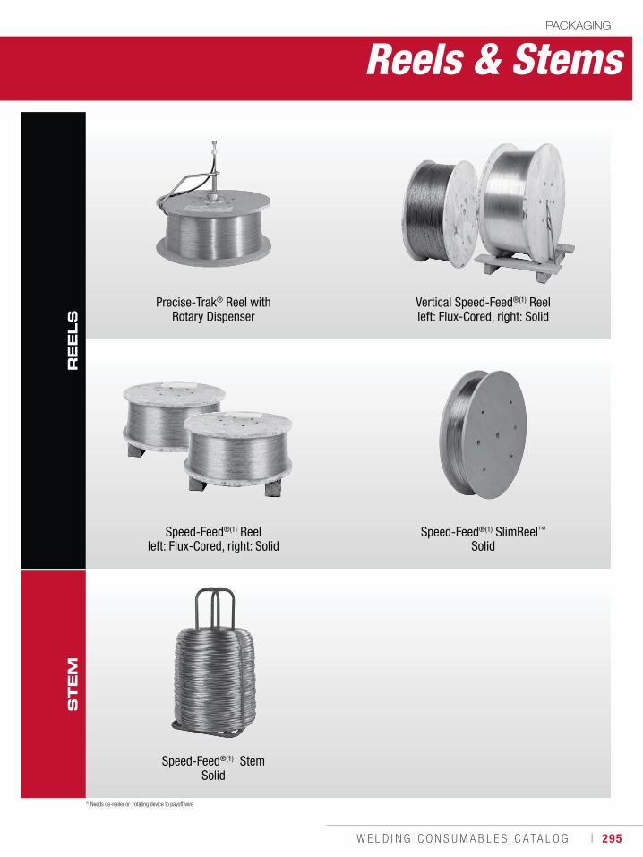
W E L D I N G C O N S U M A B L E S C A T A L O G ı 295
Reels & StemsPACKAGING
Precise-Trak® Reel with Rotary Dispenser
Vertical Speed-Feed®(1) Reel left: Flux-Cored, right: Solid
Speed-Feed®(1) Reel left: Flux-Cored, right: Solid
Speed-Feed®(1) SlimReel™Solid
Speed-Feed®(1) StemSolid
RE
EL
SS
TE
M
(1) Needs de-reeler or rotating device to payoff wire
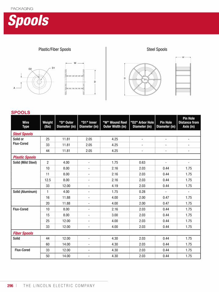
296 ı T H E L I N C O L N E L E C T R I C C O M P A N Y
SpoolsPACKAGING
SPOOLS
Wire Type
Weight (lbs)
"D" Outer Diameter (in)
"D1" Inner Diameter (in)
"W" Wound Reel Outer Width (in)
"D2" Arbor Hole Diameter (in)
Pin Hole Diameter (in)
Pin Hole Distance from
Axis (in)
Steel SpoolsSolid or Flux-Cored
25 11.81 2.05 4.25 - - -
33 11.81 2.05 4.25 - - -
44 11.81 2.05 4.25 - - -
Plastic SpoolsSolid (Mild Steel) 2 4.00 - 1.75 0.63 - -
10 8.00 - 2.16 2.03 0.44 1.75
11 8.00 - 2.16 2.03 0.44 1.75
12.5 8.00 - 2.16 2.03 0.44 1.75
33 12.00 - 4.19 2.03 0.44 1.75
Solid (Aluminum) 1 4.00 - 1.75 0.28 - -
16 11.88 - 4.00 2.00 0.47 1.75
20 11.88 - 4.00 2.00 0.47 1.75
Flux-Cored 10 8.00 - 2.16 2.03 0.44 1.75
15 8.00 - 3.00 2.03 0.44 1.75
25 12.00 - 4.00 2.03 0.44 1.75
33 12.00 - 4.00 2.03 0.44 1.75
Fiber SpoolsSolid 44 12.00 - 4.30 2.03 0.44 1.75
60 14.00 - 4.30 2.03 0.44 1.75
Flux-Cored 33 12.00 - 4.30 2.03 0.44 1.75
50 14.00 - 4.30 2.03 0.44 1.75
D2 D1
A
W
D
Plastic/Fiber Spools Steel Spools
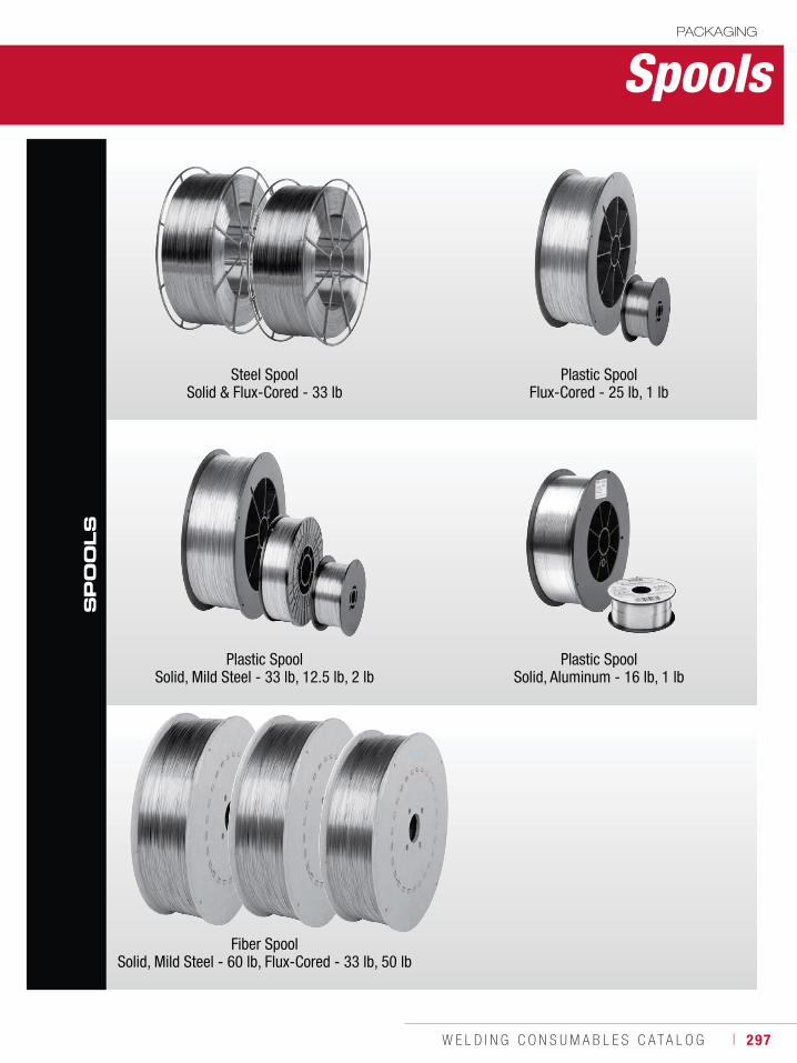
W E L D I N G C O N S U M A B L E S C A T A L O G ı 297
SpoolsPACKAGING
SP
OO
LS
Steel SpoolSolid & Flux-Cored - 33 lb
Plastic Spool Flux-Cored - 25 lb, 1 lb
Plastic SpoolSolid, Mild Steel - 33 lb, 12.5 lb, 2 lb
Plastic Spool Solid, Aluminum - 16 lb, 1 lb
Fiber SpoolSolid, Mild Steel - 60 lb, Flux-Cored - 33 lb, 50 lb
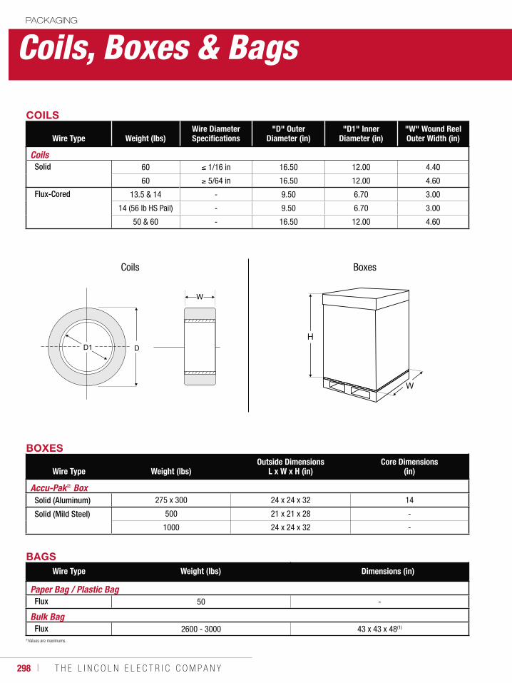
298 ı T H E L I N C O L N E L E C T R I C C O M P A N Y
Coils, Boxes & BagsPACKAGING
BOXES
Wire Type Weight (lbs)Outside Dimensions
L x W x H (in)Core Dimensions
(in)
Accu-Pak® Box Solid (Aluminum) 275 x 300 24 x 24 x 32 14
Solid (Mild Steel) 500 21 x 21 x 28 -
1000 24 x 24 x 32 -
BAGSWire Type Weight (lbs) SolidDimensions (in)
Paper Bag / Plastic Bag Flux 50 -
Bulk Bag Flux 2600 - 3000 43 x 43 x 48(1)
COILS
Wire Type Weight (lbs)Wire Diameter Specifications
"D" Outer Diameter (in)
"D1" Inner Diameter (in)
"W" Wound Reel Outer Width (in)
CoilsSolid 60 1/16 in 16.50 12.00 4.40
60 5/64 in 16.50 12.00 4.60
Flux-Cored 13.5 & 14 - 9.50 6.70 3.00
14 (56 lb HS Pail) - 9.50 6.70 3.00
50 & 60 - 16.50 12.00 4.60
D1 D
W
Coils Boxes
(1)Values are maximums.
H
W
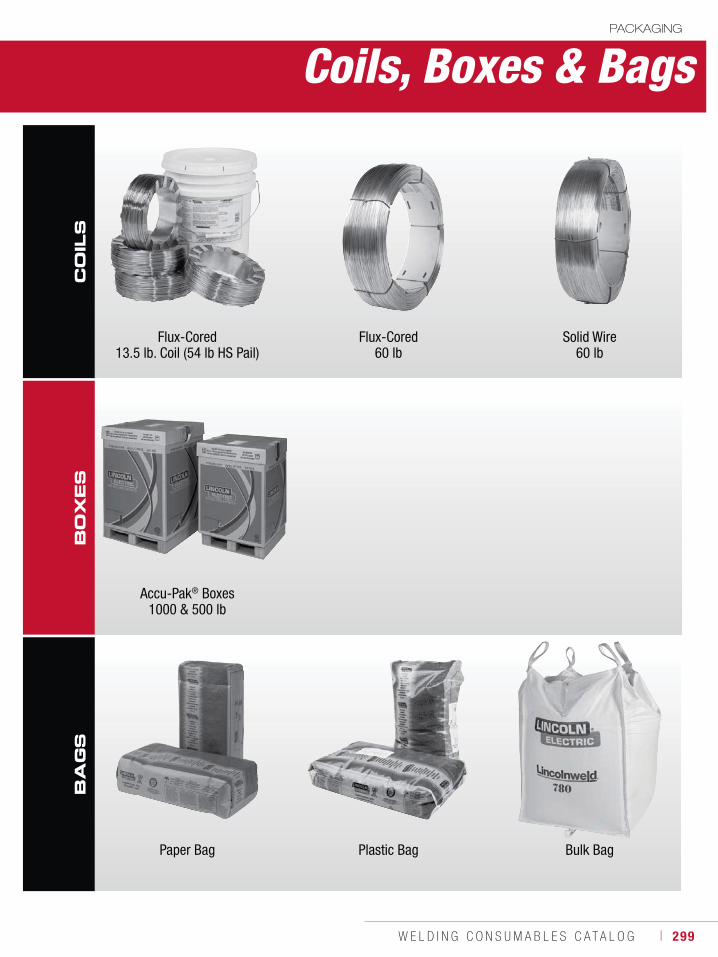
W E L D I N G C O N S U M A B L E S C A T A L O G ı 299
BO
XE
SCoils, Boxes & Bags
PACKAGING
CO
ILS
BA
GS
Flux-Cored 13.5 lb. Coil (54 lb HS Pail)
Flux-Cored60 lb
Solid Wire60 lb
Paper Bag Plastic Bag Bulk Bag
Accu-Pak® Boxes1000 & 500 lb
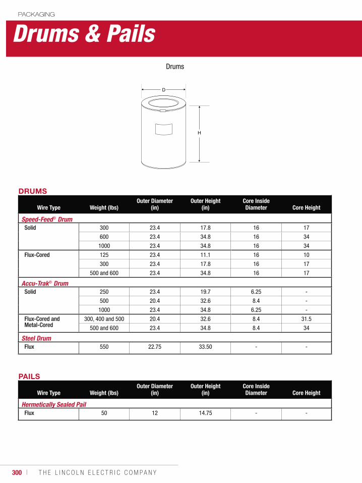
300 ı T H E L I N C O L N E L E C T R I C C O M P A N Y
Drums & PailsPACKAGING
DRUMS
Wire Type Weight (lbs)Outer Diameter
(in)Outer Height
(in)Core Inside Diameter Core Height
Speed-Feed® Drum Solid 300 23.4 17.8 16 17
600 23.4 34.8 16 34
1000 23.4 34.8 16 34
Flux-Cored 125 23.4 11.1 16 10
300 23.4 17.8 16 17
500 and 600 23.4 34.8 16 17
Accu-Trak® Drum Solid 250 23.4 19.7 6.25 -
500 20.4 32.6 8.4 -
1000 23.4 34.8 6.25 -
Flux-Cored and Metal-Cored
300, 400 and 500 20.4 32.6 8.4 31.5
500 and 600 23.4 34.8 8.4 34
Steel Drum Flux 550 22.75 33.50 - -
PAILS
Wire Type Weight (lbs)Outer Diameter
(in)Outer Height
(in)Core Inside Diameter Core Height
Hermetically Sealed PailFlux 50 12 14.75 - -
D
H
Drums
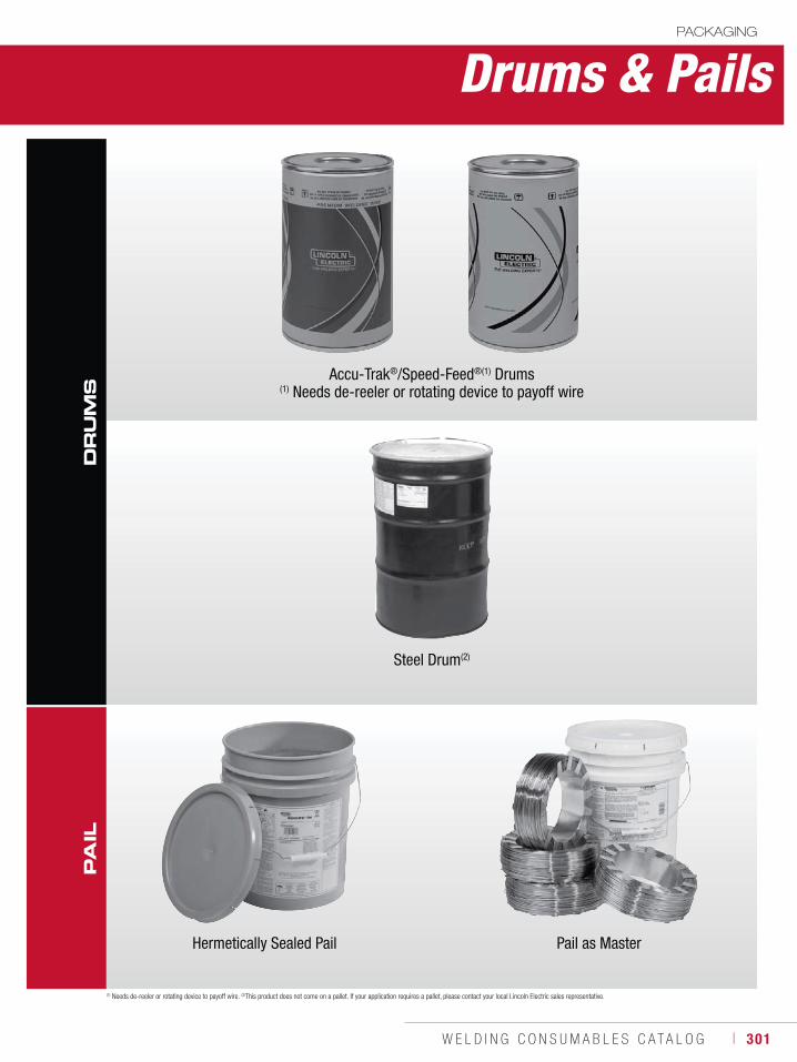
W E L D I N G C O N S U M A B L E S C A T A L O G ı 301
DR
UM
SP
AIL
Drums & PailsPACKAGING
Accu-Trak®/Speed-Feed®(1) Drums(1) Needs de-reeler or rotating device to payoff wire
(1) Needs de-reeler or rotating device to payoff wire. (2)This product does not come on a pallet. If your application requires a pallet, please contact your local Lincoln Electric sales representative.
Steel Drum(2)
Hermetically Sealed Pail Pail as Master
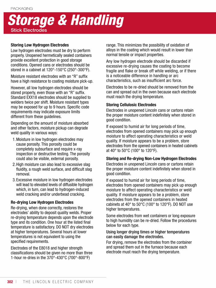
302 ı T H E L I N C O L N E L E C T R I C C O M P A N Y
Storage & HandlingPACKAGING
Storing Low Hydrogen ElectrodesLow hydrogen electrodes must be dry to perform properly. Unopened hermetically sealed containers provide excellent protection in good storage conditions. Opened cans or electrodes should be stored in a cabinet at 120°-150°C (250°-300°F).
Moisture resistant electrodes with an “R” suffix have a high resistance to coating moisture pick-up.
However, all low hydrogen electrodes should be stored properly, even those with an “R” suffix. Standard EXX18 electrodes should be supplied to welders twice per shift. Moisture resistant types may be exposed for up to 9 hours. Specific code requirements may indicate exposure limits different from these guidelines.
Depending on the amount of moisture absorbed and other factors, moisture pickup can degrade weld quality in various ways:
1. Moisture in low hydrogen electrodes may cause porosity. This porosity could be completely subsurface and require x-ray inspection or destructive testing. The porosity could also be visible, external porosity.
2. High moisture can also lead to excessive slag fluidity, a rough weld surface, and difficult slag removal.
3. Excessive moisture in low hydrogen electrodes will lead to elevated levels of diffusible hydrogen which, in turn, can lead to hydrogen-induced weld cracking and/or underbead cracking.
Re-drying Low Hydrogen ElectrodesRe-drying, when done correctly, restores the electrodes’ ability to deposit quality welds. Proper re-drying temperature depends upon the electrode type and its condition. One hour at the listed final temperature is satisfactory. DO NOT dry electrodes at higher temperatures. Several hours at lower temperatures is not equivalent to using the specified requirements.
Electrodes of the E8018 and higher strength classifications should be given no more than three 1-hour re-dries in the 370°-430°C (700°-800°F)
range. This minimizes the possibility of oxidation of alloys in the coating which would result in lower than normal tensile or impact properties.
Any low hydrogen electrode should be discarded if excessive re-drying causes the coating to become fragile and flake or break off while welding, or if there is a noticeable difference in handling or arc characteristics, such as insufficient arc force.
Electrodes to be re-dried should be removed from the can and spread out in the oven because each electrode must reach the drying temperature.
Storing Cellulosic ElectrodesElectrodes in unopened Lincoln cans or cartons retain the proper moisture content indefinitely when stored in good condition.
If exposed to humid air for long periods of time, electrodes from opened containers may pick up enough moisture to affect operating characteristics or weld quality. If moisture appears to be a problem, store electrodes from the opened containers in heated cabinets at 40° to 50°C (100° to 120°F).
Storing and Re-drying Non-Low Hydrogen ElectrodesElectrodes in unopened Lincoln cans or cartons retain the proper moisture content indefinitely when stored in good condition.
If exposed to humid air for long periods of time, electrodes from opened containers may pick up enough moisture to affect operating characteristics or weld quality. If moisture appears to be a problem, store electrodes from the opened containers in heated cabinets at 40° to 50°C (100° to 120°F). DO NOT use higher temperatures.
Some electrodes from wet containers or long exposure to high humidity can be re-dried. Follow the procedures below for each type.
Using longer drying times or higher temperatures can easily damage the electrodes.For drying, remove the electrodes from the container and spread them out in the furnace because each electrode must reach the drying temperature.
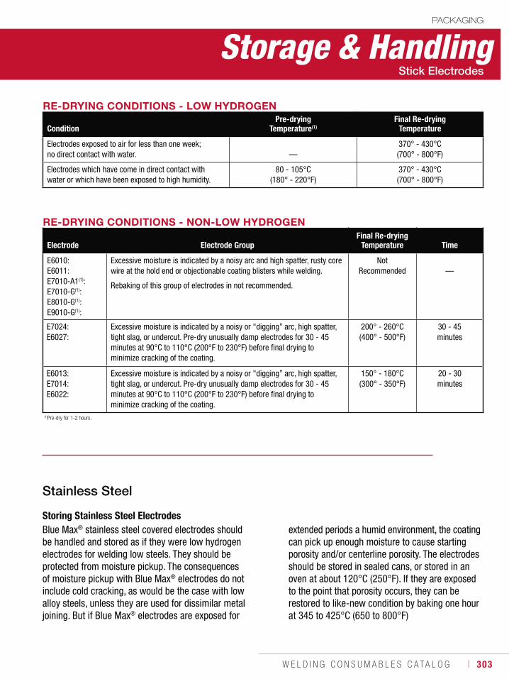
W E L D I N G C O N S U M A B L E S C A T A L O G ı 303
Storage & HandlingPACKAGING
RE-DRYING CONDITIONS - LOW HYDROGEN
ConditionPre-drying
Temperature(1)Final Re-drying
Temperature
Electrodes exposed to air for less than one week; no direct contact with water. —
370° - 430°C(700° - 800°F)
Electrodes which have come in direct contact with water or which have been exposed to high humidity.
80 - 105°C(180° - 220°F)
370° - 430°C(700° - 800°F)
RE-DRYING CONDITIONS - NON-LOW HYDROGEN
Electrode Electrode GroupFinal Re-drying
Temperature Time
E6010: E6011: E7010-A1(1): E7010-G(1):E8010-G(1):E9010-G(1):
Excessive moisture is indicated by a noisy arc and high spatter, rusty core wire at the hold end or objectionable coating blisters while welding.
Rebaking of this group of electrodes in not recommended.
NotRecommended —
E7024:E6027:
Excessive moisture is indicated by a noisy or "digging” arc, high spatter, tight slag, or undercut. Pre-dry unusually damp electrodes for 30 - 45 minutes at 90°C to 110°C (200°F to 230°F) before final drying to minimize cracking of the coating.
200° - 260°C(400° - 500°F)
30 - 45minutes
E6013: E7014:E6022:
Excessive moisture is indicated by a noisy or "digging” arc, high spatter, tight slag, or undercut. Pre-dry unusually damp electrodes for 30 - 45 minutes at 90°C to 110°C (200°F to 230°F) before final drying to minimize cracking of the coating.
150° - 180°C(300° - 350°F)
20 - 30minutes
(1)Pre-dry for 1-2 hours.
Storing Stainless Steel ElectrodesBlue Max® stainless steel covered electrodes should be handled and stored as if they were low hydrogen electrodes for welding low steels. They should be protected from moisture pickup. The consequences of moisture pickup with Blue Max® electrodes do not include cold cracking, as would be the case with low alloy steels, unless they are used for dissimilar metal joining. But if Blue Max® electrodes are exposed for
extended periods a humid environment, the coating can pick up enough moisture to cause starting porosity and/or centerline porosity. The electrodes should be stored in sealed cans, or stored in an oven at about 120°C (250°F). If they are exposed to the point that porosity occurs, they can be restored to like-new condition by baking one hour at 345 to 425°C (650 to 800°F)
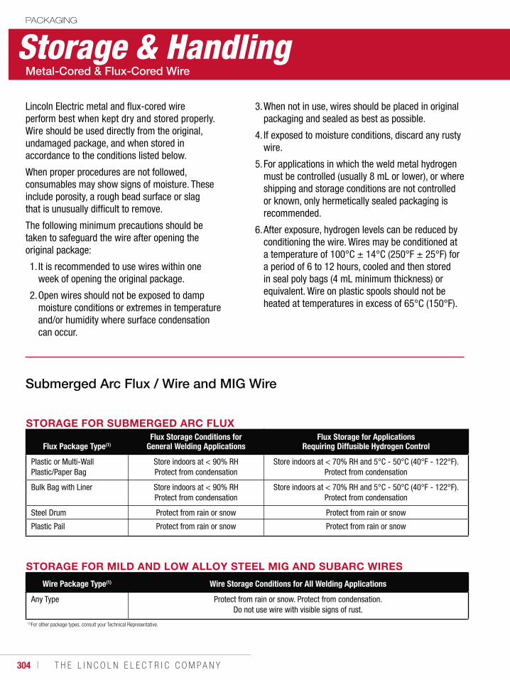
304 ı T H E L I N C O L N E L E C T R I C C O M P A N Y
Storage & HandlingPACKAGING
Lincoln Electric metal and flux-cored wire perform best when kept dry and stored properly. Wire should be used directly from the original, undamaged package, and when stored in accordance to the conditions listed below.
When proper procedures are not followed, consumables may show signs of moisture. These include porosity, a rough bead surface or slag that is unusually difficult to remove.
The following minimum precautions should be taken to safeguard the wire after opening the original package:
1. It is recommended to use wires within one week of opening the original package.
2. Open wires should not be exposed to damp moisture conditions or extremes in temperature and/or humidity where surface condensation can occur.
3. When not in use, wires should be placed in original packaging and sealed as best as possible.
4. If exposed to moisture conditions, discard any rusty wire.
5. For applications in which the weld metal hydrogen must be controlled (usually 8 mL or lower), or where shipping and storage conditions are not controlled or known, only hermetically sealed packaging is recommended.
6. After exposure, hydrogen levels can be reduced by conditioning the wire. Wires may be conditioned at a temperature of 100°C ± 14°C (250°F ± 25°F) for a period of 6 to 12 hours, cooled and then stored in seal poly bags (4 mL minimum thickness) or equivalent. Wire on plastic spools should not be heated at temperatures in excess of 65°C (150°F).
STORAGE FOR MILD AND LOW ALLOY STEEL MIG AND SUBARC WIRES
Wire Package Type(1) Wire Storage Conditions for All Welding Applications
Any Type Protect from rain or snow. Protect from condensation. Do not use wire with visible signs of rust.
STORAGE FOR SUBMERGED ARC FLUX
Flux Package Type(1)Flux Storage Conditions for
General Welding ApplicationsFlux Storage for Applications
Requiring Diffusible Hydrogen Control
Plastic or Multi-WallPlastic/Paper Bag
Store indoors at < 90% RH Protect from condensation
Store indoors at < 70% RH and 5°C - 50°C (40°F - 122°F).Protect from condensation
Bulk Bag with Liner Store indoors at < 90% RH Protect from condensation
Store indoors at < 70% RH and 5°C - 50°C (40°F - 122°F).Protect from condensation
Steel Drum Protect from rain or snow Protect from rain or snow
Plastic Pail Protect from rain or snow Protect from rain or snow
(1)For other package types, consult your Technical Representative.
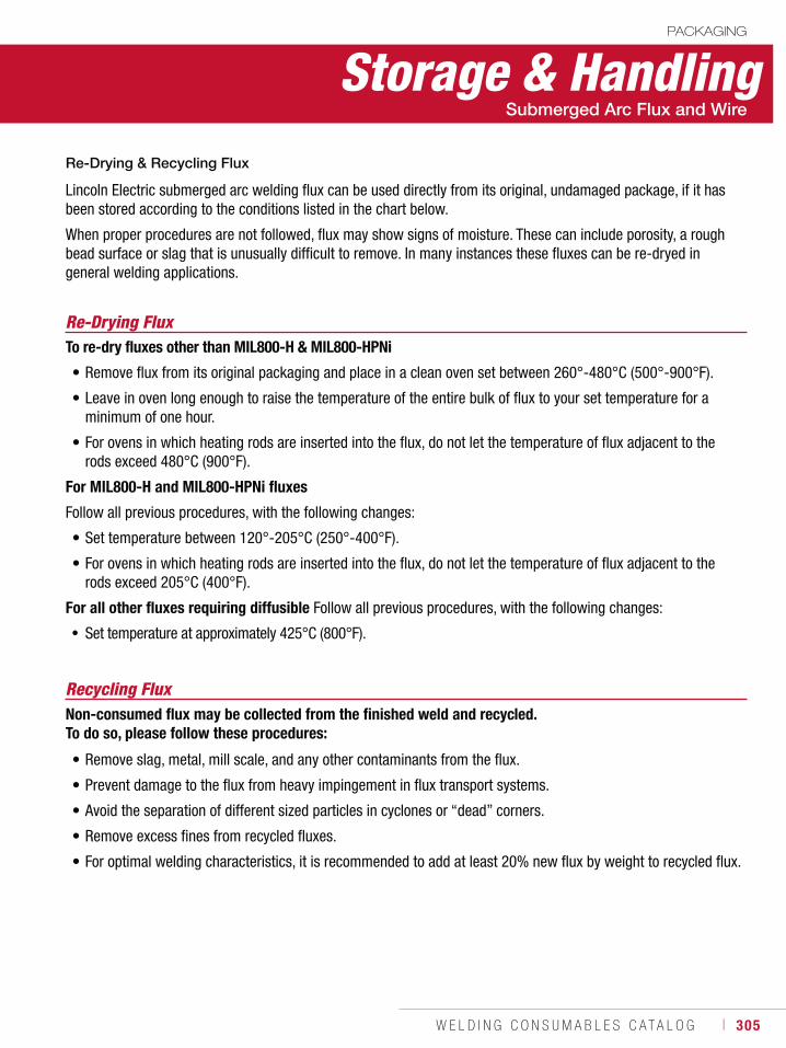
W E L D I N G C O N S U M A B L E S C A T A L O G ı 305
Storage & HandlingPACKAGING
Re-Drying FluxTo re-dry fluxes other than MIL800-H & MIL800-HPNi
• Remove flux from its original packaging and place in a clean oven set between 260°-480°C (500°-900°F).
• Leave in oven long enough to raise the temperature of the entire bulk of flux to your set temperature for a minimum of one hour.
• For ovens in which heating rods are inserted into the flux, do not let the temperature of flux adjacent to the rods exceed 480°C (900°F).
For MIL800-H and MIL800-HPNi fluxes
Follow all previous procedures, with the following changes:
• Set temperature between 120°-205°C (250°-400°F).
• For ovens in which heating rods are inserted into the flux, do not let the temperature of flux adjacent to the rods exceed 205°C (400°F).
For all other fluxes requiring diffusible Follow all previous procedures, with the following changes:
Set temperature at approximately 425°C (800°F).
Lincoln Electric submerged arc welding flux can be used directly from its original, undamaged package, if it has been stored according to the conditions listed in the chart below.
When proper procedures are not followed, flux may show signs of moisture. These can include porosity, a rough bead surface or slag that is unusually difficult to remove. In many instances these fluxes can be re-dryed in general welding applications.
Recycling Flux
• Remove slag, metal, mill scale, and any other contaminants from the flux.
• Prevent damage to the flux from heavy impingement in flux transport systems.
• Avoid the separation of different sized particles in cyclones or “dead” corners.
• Remove excess fines from recycled fluxes.
• For optimal welding characteristics, it is recommended to add at least 20% new flux by weight to recycled flux.
Non-consumed flux may be collected from the finished weld and recycled. To do so, please follow these procedures:
306 ı T H E L I N C O L N E L E C T R I C C O M P A N Y
NotesPACKAGING
W E L D I N G C O N S U M A B L E S C A T A L O G ı 307
CONSUMABLES
APPENDIXAWS Classification System
Stick ............................................................308MIG, TIG & Metal-Cored ................................309Flux-Cored ...................................................310Submerged Arc ............................................312
General InformationStick ElectrodeTypes of Coating & Current ...........................314ASME Boiler & Pressure Vessel Code ............315
Submerged ArcFlux Types & General Characteristics ............316Selecting Flux/Wire Combinations ................317
HardfacingCross Checking ............................................319
AluminumTypical Operating Procedures .......................320Typical Joint Designs ....................................322
Innershield®
Wire Selection Guide ....................................323
Pipeliner®
Electrode Selection Guide .............................325LH-D80/90/100 Welding Guidelines ..............328EN and ISO Classifications ............................329
Agency Approvals ................................. 331
Safety Guidelines .................................. 344
District Sales Offices............................. 352
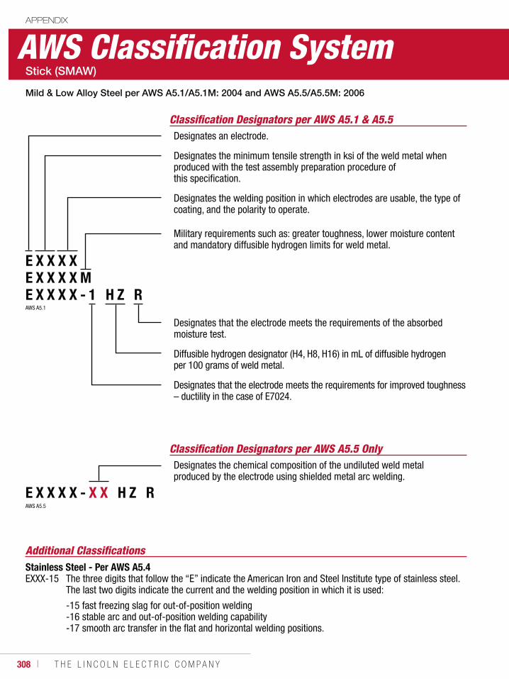
308 ı T H E L I N C O L N E L E C T R I C C O M P A N Y
AWS Classification SystemAPPENDIX
Classification Designators per AWS A5.1 & A5.5Designates an electrode.
Designates the minimum tensile strength in ksi of the weld metal when produced with the test assembly preparation procedure of this specification.
Designates the welding position in which electrodes are usable, the type of coating, and the polarity to operate.
Military requirements such as: greater toughness, lower moisture content and mandatory diffusible hydrogen limits for weld metal.
Designates that the electrode meets the requirements of the absorbed moisture test.
Diffusible hydrogen designator (H4, H8, H16) in mL of diffusible hydrogen per 100 grams of weld metal.
Designates that the electrode meets the requirements for improved toughness – ductility in the case of E7024.
E X X X XE X X X X ME X X X X - 1 H Z R
Classification Designators per AWS A5.5 OnlyDesignates the chemical composition of the undiluted weld metal produced by the electrode using shielded metal arc welding.
E X X X X - X X H Z R
AWS A5.1
AWS A5.5
Additional ClassificationsStainless Steel - Per AWS A5.4EXXX-15 The three digits that follow the “E” indicate the American Iron and Steel Institute type of stainless steel.
The last two digits indicate the current and the welding position in which it is used:
-15 fast freezing slag for out-of-position welding -16 stable arc and out-of-position welding capability -17 smooth arc transfer in the flat and horizontal welding positions.
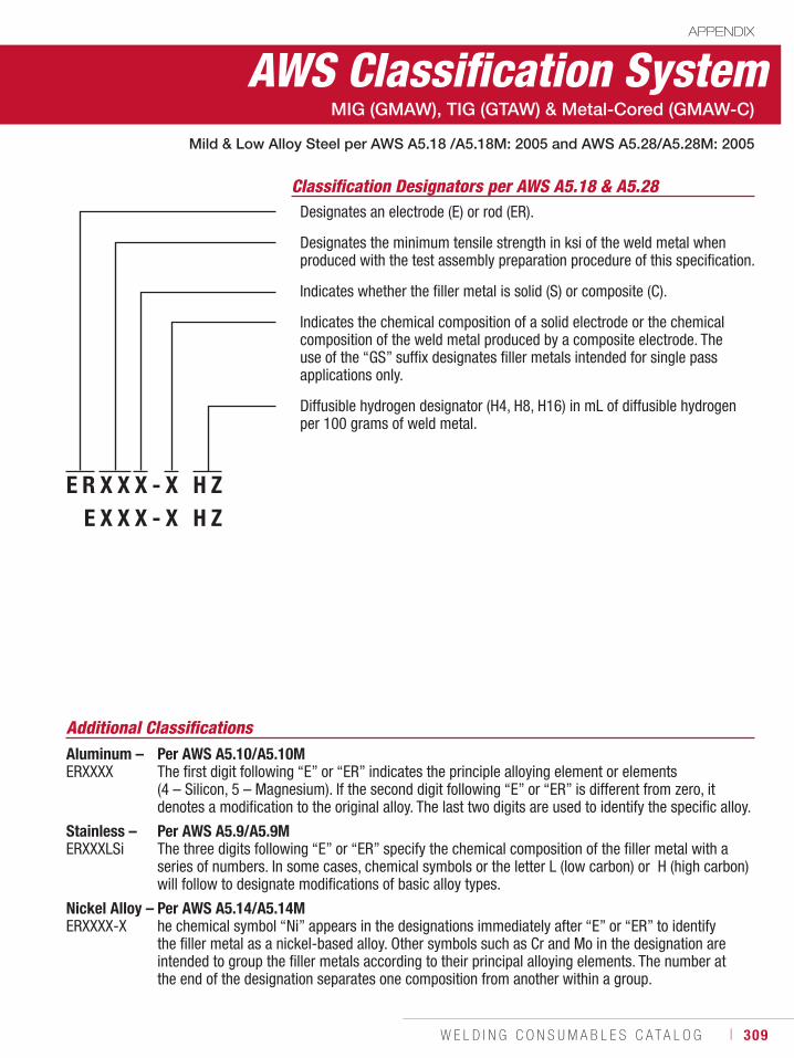
W E L D I N G C O N S U M A B L E S C A T A L O G ı 309
AWS Classification SystemAPPENDIX
Classification Designators per AWS A5.18 & A5.28Designates an electrode (E) or rod (ER).
Designates the minimum tensile strength in ksi of the weld metal when produced with the test assembly preparation procedure of this specification.
Indicates whether the filler metal is solid (S) or composite (C).
Indicates the chemical composition of a solid electrode or the chemical composition of the weld metal produced by a composite electrode. The use of the “GS” suffix designates filler metals intended for single pass applications only.
Diffusible hydrogen designator (H4, H8, H16) in mL of diffusible hydrogen per 100 grams of weld metal.
MIG (GMAW), TIG (GTAW) & Metal-Cored (GMAW-C)
Mild & Low Alloy Steel per AWS A5.18 /A5.18M: 2005 and AWS A5.28/A5.28M: 2005
E R X X X - X H ZR E X X X - X H Z
Additional ClassificationsAluminum – Per AWS A5.10/A5.10MERXXXX The first digit following “E” or “ER” indicates the principle alloying element or elements
(4 – Silicon, 5 – Magnesium). If the second digit following “E” or “ER” is different from zero, it denotes a modification to the original alloy. The last two digits are used to identify the specific alloy.
Stainless – Per AWS A5.9/A5.9MERXXXLSi The three digits following “E” or “ER” specify the chemical composition of the filler metal with a
series of numbers. In some cases, chemical symbols or the letter L (low carbon) or H (high carbon) will follow to designate modifications of basic alloy types.
Nickel Alloy – Per AWS A5.14/A5.14MERXXXX-X he chemical symbol “Ni” appears in the designations immediately after “E” or “ER” to identify
the filler metal as a nickel-based alloy. Other symbols such as Cr and Mo in the designation are intended to group the filler metals according to their principal alloying elements. The number at the end of the designation separates one composition from another within a group.
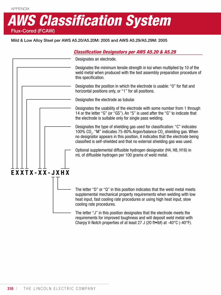
310 ı T H E L I N C O L N E L E C T R I C C O M P A N Y
AWS Classification SystemAPPENDIX
Classification Designators per AWS A5.20 & A5.29Designates an electrode.
Designates the minimum tensile strength in ksi when multiplied by 10 of the weld metal when produced with the test assembly preparation procedure of this specification.
Designates the position in which the electrode is usable: “0” for flat and horizontal positions only, or “1” for all positions.
Designates the electrode as tubular.
Designates the usability of the electrode with some number from 1 through 14 or the letter “G” (or “GS”). An “S” is used after the “G” to indicate that the electrode is suitable only for single pass welding.
Designates the type of shielding gas used for classification: “C” indicates 100% CO2. “M” indicates 75-80% Argon/balance CO2 shielding gas. When no designator appears in this position, it indicates that the electrode being classified is self-shielded and that no external shielding gas was used.
Optional supplemental diffusible hydrogen designator (H4, H8, H16) in mL of diffusible hydrogen per 100 grams of weld metal.
The letter “D” or “Q” in this position indicates that the weld metal meets supplemental mechanical property requirements when welding with low heat input, fast cooling rate procedures or using high heat input, slow cooling rate procedures.
The letter “J” in this position designates that the electrode meets the requirements for improved toughness and will deposit weld metal with Charpy V-Notch properties of at least 27 J (20 ft•lbf) at -40°C (-40°F).
E X X T X - X X - J X H X
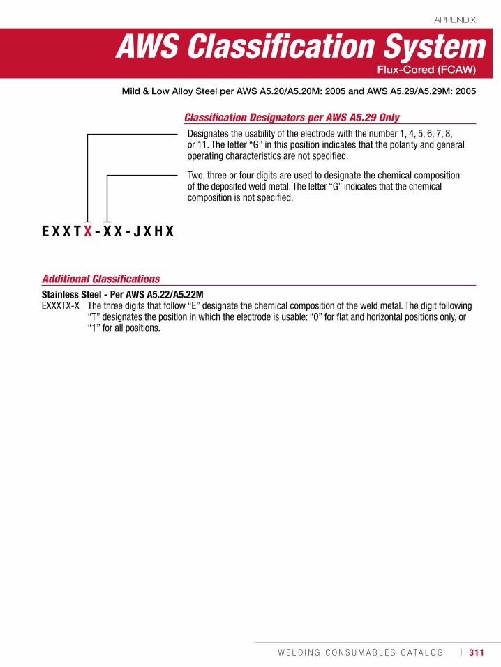
W E L D I N G C O N S U M A B L E S C A T A L O G ı 311
AWS Classification SystemAPPENDIX
Additional ClassificationsStainless Steel - Per AWS A5.22/A5.22M EXXXTX-X The three digits that follow “E” designate the chemical composition of the weld metal. The digit following “T” designates the position in which the electrode is usable: “0” for flat and horizontal positions only, or “1” for all positions.
E X X T X - X X - J X H X
Designates the usability of the electrode with the number 1, 4, 5, 6, 7, 8, or 11. The letter “G” in this position indicates that the polarity and general operating characteristics are not specified.
Two, three or four digits are used to designate the chemical composition of the deposited weld metal. The letter “G” indicates that the chemical composition is not specified.
Classification Designators per AWS A5.29 Only
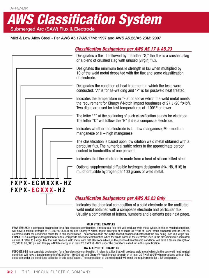
312 ı T H E L I N C O L N E L E C T R I C C O M P A N Y
APPENDIX
AWS Classification System
Classification Designators per AWS A5.17 & A5.23Designates a flux. If followed by the letter “S,” the flux is a crushed slag or a blend of crushed slag with unused (virgin) flux.
Designates the minimum tensile strength in ksi when multiplied by 10 of the weld metal deposited with the flux and some classification of electrode.
Designates the condition of heat treatment in which the tests were conducted: “A” is for as-welding and “P” is for postweld heat treated.
Indicates the temperature in °F at or above which the weld metal meets the requirement for Charpy V-Notch impact toughness of 27 J (20 ft•lbf). Two digits are used for test temperatures of -100°F or lower.
The letter “E” at the beginning of each classification stands for electrode. The letter “C” will follow the “E” if it is a composite electrode.
Indicates whether the electrode is L – low manganese, M – medium manganese or H – high manganese.
The classification is based upon low dilution weld metal obtained with a particular flux. The numerical suffix refers to the approximate carbon content in hundredths of one percent.
Indicates that the electrode is made from a heat of silicon-killed steel.
Optional supplemental diffusible hydrogen designator (H4, H8, H16) in mL of diffusible hydrogen per 100 grams of weld metal.
Classification Designators per AWS A5.23 OnlyIndicates the chemical composition of a solid electrode or the undiluted weld metal obtained with a composite electrode and particular flux. Usually a combination of letters, numbers and elements (see next page).
F X P X - E C M X X K - H ZF X P X - E C X X X - H Z
MILD STEEL EXAMPLESF7A6-EM12K is a complete designation for a flux-electrode combination. It refers to a flux that will produce weld metal which, in the as-welded condition,will have a tensile strength of 70,000 to 95,000 psi and Charpy V-Notch impact strength of at least 20 ft•lbf at -60°F when produced with an EM12K electrode under the conditions called for in this specification. The absence of an “S” in the second position indicates that the flux being used is a virgin flux. F7P4-EC1 is a complete designation for a flux-composite electrode combination when the trade name of the electrode used in the classification is indicated as well. It refers to a virgin flux that will produce weld metal with that electrode which, in the postweld heat treated condition, will have a tensile strength of 70,000 to 95,000 psi and Charpy V-Notch energy of at least 20 ft•lbf at -40°F under the conditions called for in this specification.
LOW ALLOY STEEL EXAMPLESF9P0-EB3-B3 is a complete designation for a flux-electrode combination. It refers to a flux that will produce weld metal which, in the postweld heat treated condition, will have a tensile strength of 90,000 to 110,000 psi and Charpy V-Notch impact strength of at least 20 ft•lbf at 0°F when produced with an EB3 electrode under the conditions called for in this specification. The composition of the weld metal will meet the requirements for a B3 designation.
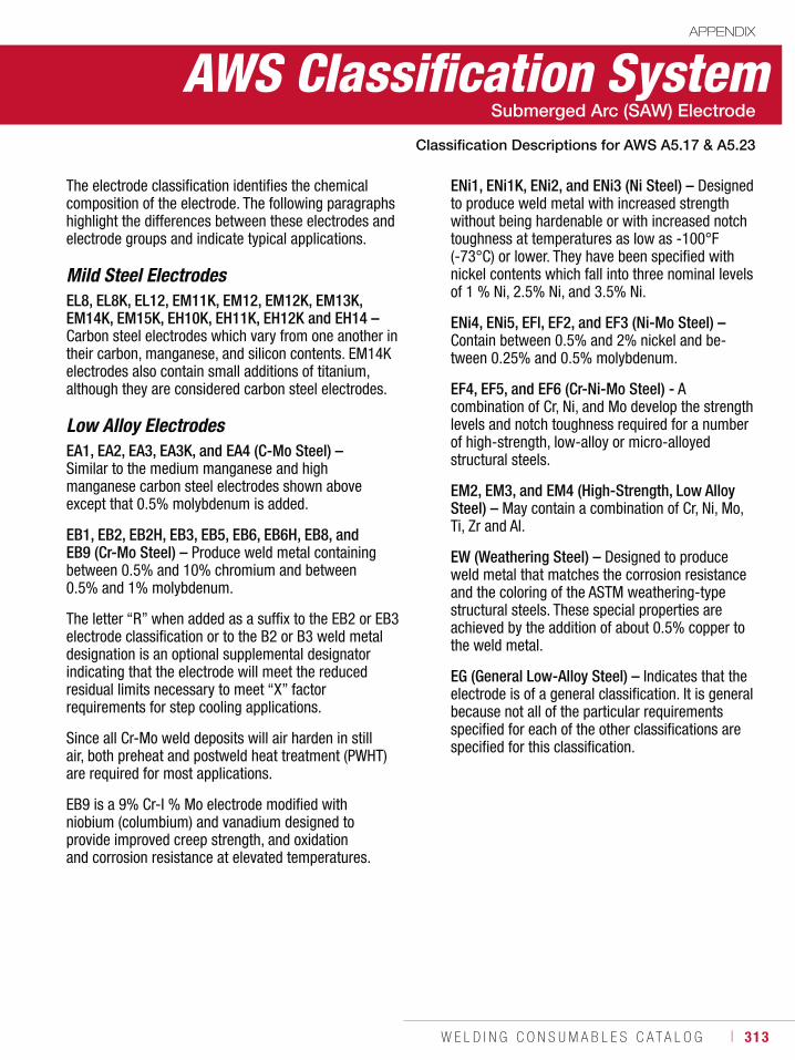
W E L D I N G C O N S U M A B L E S C A T A L O G ı 313
The electrode classification identifies the chemical composition of the electrode. The following paragraphs highlight the differences between these electrodes and electrode groups and indicate typical applications.
Mild Steel ElectrodesEL8, EL8K, EL12, EM11K, EM12, EM12K, EM13K, EM14K, EM15K, EH10K, EH11K, EH12K and EH14 – Carbon steel electrodes which vary from one another in their carbon, manganese, and silicon contents. EM14K electrodes also contain small additions of titanium, although they are considered carbon steel electrodes.
Low Alloy ElectrodesEA1, EA2, EA3, EA3K, and EA4 (C-Mo Steel) – Similar to the medium manganese and high manganese carbon steel electrodes shown above except that 0.5% molybdenum is added.
EB1, EB2, EB2H, EB3, EB5, EB6, EB6H, EB8, and EB9 (Cr-Mo Steel) – Produce weld metal containing between 0.5% and 10% chromium and between 0.5% and 1% molybdenum.
The letter “R” when added as a suffix to the EB2 or EB3 electrode classification or to the B2 or B3 weld metal designation is an optional supplemental designator indicating that the electrode will meet the reduced residual limits necessary to meet “X” factor requirements for step cooling applications.
Since all Cr-Mo weld deposits will air harden in still air, both preheat and postweld heat treatment (PWHT) are required for most applications.
EB9 is a 9% Cr-I % Mo electrode modified with niobium (columbium) and vanadium designed to provide improved creep strength, and oxidation and corrosion resistance at elevated temperatures.
AWS Classification SystemAPPENDIX
ENi1, ENi1K, ENi2, and ENi3 (Ni Steel) – Designed to produce weld metal with increased strength without being hardenable or with increased notch toughness at temperatures as low as -100°F (-73°C) or lower. They have been specified with nickel contents which fall into three nominal levels of 1 % Ni, 2.5% Ni, and 3.5% Ni.
ENi4, ENi5, EFl, EF2, and EF3 (Ni-Mo Steel) – Contain between 0.5% and 2% nickel and be-tween 0.25% and 0.5% molybdenum.
EF4, EF5, and EF6 (Cr-Ni-Mo Steel) - A combination of Cr, Ni, and Mo develop the strength levels and notch toughness required for a number of high-strength, low-alloy or micro-alloyed structural steels.
EM2, EM3, and EM4 (High-Strength, Low Alloy Steel) – May contain a combination of Cr, Ni, Mo, Ti, Zr and Al.
EW (Weathering Steel) – Designed to produce weld metal that matches the corrosion resistance and the coloring of the ASTM weathering-type structural steels. These special properties are achieved by the addition of about 0.5% copper to the weld metal.
EG (General Low-Alloy Steel) – Indicates that the electrode is of a general classification. It is general because not all of the particular requirements specified for each of the other classifications are specified for this classification.
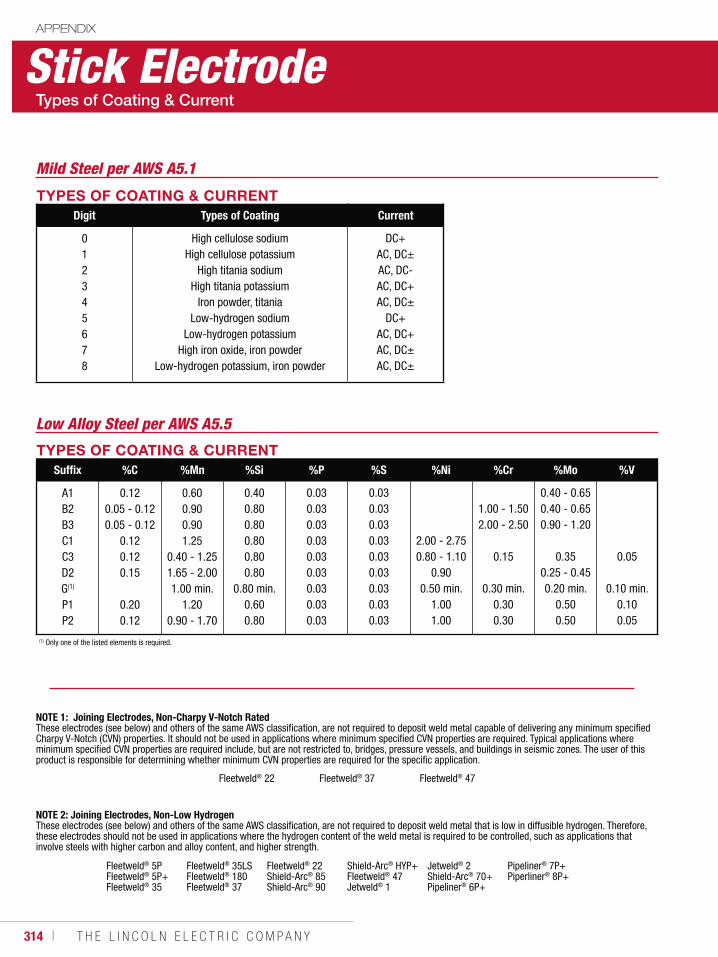
314 ı T H E L I N C O L N E L E C T R I C C O M P A N Y
Stick ElectrodeAPPENDIX
TYPES OF COATING & CURRENTDigit Types of Coating Current
012345678
High cellulose sodiumHigh cellulose potassium
High titania sodiumHigh titania potassium
Iron powder, titaniaLow-hydrogen sodium
Low-hydrogen potassiumHigh iron oxide, iron powder
Low-hydrogen potassium, iron powder
DC+AC, DC±AC, DC-AC, DC+AC, DC±
DC+AC, DC+AC, DC±AC, DC±
TYPES OF COATING & CURRENTSuffix %C %Mn %Si %P %S %Ni %Cr %Mo %V
A1B2B3C1C3D2G(1)
P1P2
0.120.05 - 0.120.05 - 0.12
0.120.120.15
0.200.12
0.600.900.901.25
0.40 - 1.251.65 - 2.001.00 min.
1.200.90 - 1.70
0.400.800.800.800.800.80
0.80 min.0.600.80
0.030.030.030.030.030.030.030.030.03
0.030.030.030.030.030.030.030.030.03
2.00 - 2.750.80 - 1.10
0.900.50 min.
1.001.00
1.00 - 1.502.00 - 2.50
0.15
0.30 min.0.300.30
0.40 - 0.650.40 - 0.650.90 - 1.20
0.350.25 - 0.450.20 min.
0.500.50
0.05
0.10 min.0.100.05
(1) Only one of the listed elements is required.
NOTE 1: Joining Electrodes, Non-Charpy V-Notch RatedThese electrodes (see below) and others of the same AWS classification, are not required to deposit weld metal capable of delivering any minimum specified Charpy V-Notch (CVN) properties. It should not be used in applications where minimum specified CVN properties are required. Typical applications where minimum specified CVN properties are required include, but are not restricted to, bridges, pressure vessels, and buildings in seismic zones. The user of this product is responsible for determining whether minimum CVN properties are required for the specific application.
Fleetweld® 22 Fleetweld® 37 Fleetweld® 47
NOTE 2: Joining Electrodes, Non-Low HydrogenThese electrodes (see below) and others of the same AWS classification, are not required to deposit weld metal that is low in diffusible hydrogen. Therefore, these electrodes should not be used in applications where the hydrogen content of the weld metal is required to be controlled, such as applications that involve steels with higher carbon and alloy content, and higher strength.
Fleetweld® 5PFleetweld® 5P+Fleetweld® 35
Fleetweld® 35LSFleetweld® 180Fleetweld® 37
Fleetweld® 22Shield-Arc® 85Shield-Arc® 90
Shield-Arc® HYP+Fleetweld® 47 Jetweld® 1
Jetweld® 2Shield-Arc® 70+Pipeliner® 6P+
Pipeliner® 7P+Piperliner® 8P+
Mild Steel per AWS A5.1
Low Alloy Steel per AWS A5.5
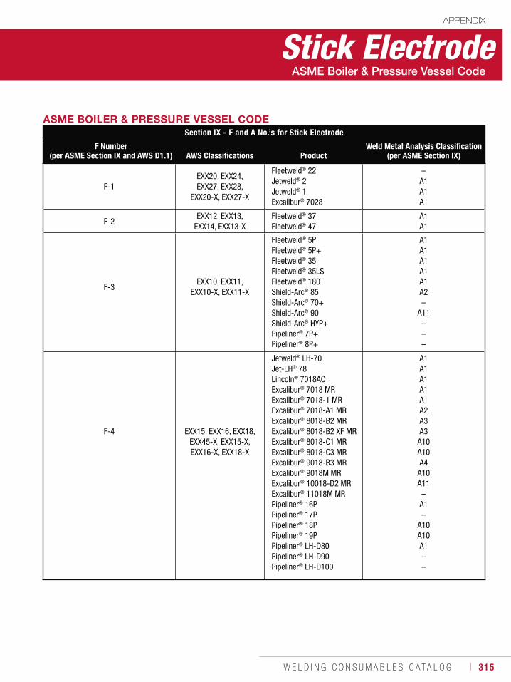
W E L D I N G C O N S U M A B L E S C A T A L O G ı 315
Stick ElectrodeAPPENDIX
ASME BOILER & PRESSURE VESSEL CODESection IX - F and A No.’s for Stick Electrode
F Number(per ASME Section IX and AWS D1.1) AWS Classifications Product
Weld Metal Analysis Classification(per ASME Section IX)
F-1EXX20, EXX24, EXX27, EXX28,
EXX20-X, EXX27-X
Fleetweld® 22Jetweld® 2Jetweld® 1Excalibur® 7028
–A1A1A1
F-2EXX12, EXX13,
EXX14, EXX13-XFleetweld® 37Fleetweld® 47
A1A1
F-3EXX10, EXX11,
EXX10-X, EXX11-X
Fleetweld® 5PFleetweld® 5P+Fleetweld® 35Fleetweld® 35LSFleetweld® 180Shield-Arc® 85Shield-Arc® 70+Shield-Arc® 90Shield-Arc® HYP+Pipeliner® 7P+Pipeliner® 8P+
A1A1A1A1A1A2–
A11–––
F-4 EXX15, EXX16, EXX18,EXX45-X, EXX15-X, EXX16-X, EXX18-X
Jetweld® LH-70Jet-LH® 78Lincoln® 7018ACExcalibur® 7018 MRExcalibur® 7018-1 MRExcalibur® 7018-A1 MRExcalibur® 8018-B2 MRExcalibur® 8018-B2 XF MRExcalibur® 8018-C1 MRExcalibur® 8018-C3 MRExcalibur® 9018-B3 MRExcalibur® 9018M MRExcalibur® 10018-D2 MRExcalibur® 11018M MRPipeliner® 16PPipeliner® 17PPipeliner® 18PPipeliner® 19PPipeliner® LH-D80Pipeliner® LH-D90Pipeliner® LH-D100
A1A1A1A1A1A2A3A3
A10A10A4
A10A11
–A1–
A10A10A1––
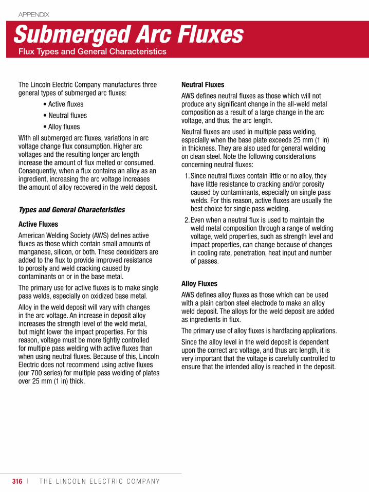
316 ı T H E L I N C O L N E L E C T R I C C O M P A N Y
Submerged Arc FluxesAPPENDIX
The Lincoln Electric Company manufactures three general types of submerged arc fluxes:
• Active fluxes
• Neutral fluxes
• Alloy fluxes
With all submerged arc fluxes, variations in arc voltage change flux consumption. Higher arc voltages and the resulting longer arc length increase the amount of flux melted or consumed. Consequently, when a flux contains an alloy as an ingredient, increasing the arc voltage increases the amount of alloy recovered in the weld deposit.
Types and General Characteristics
Active Fluxes
American Welding Society (AWS) defines active fluxes as those which contain small amounts of manganese, silicon, or both. These deoxidizers are added to the flux to provide improved resistance to porosity and weld cracking caused by contaminants on or in the base metal.
The primary use for active fluxes is to make single pass welds, especially on oxidized base metal.
Alloy in the weld deposit will vary with changes in the arc voltage. An increase in deposit alloy increases the strength level of the weld metal, but might lower the impact properties. For this reason, voltage must be more tightly controlled for multiple pass welding with active fluxes than when using neutral fluxes. Because of this, Lincoln Electric does not recommend using active fluxes (our 700 series) for multiple pass welding of plates over 25 mm (1 in) thick.
Neutral Fluxes
AWS defines neutral fluxes as those which will not produce any significant change in the all-weld metal composition as a result of a large change in the arc voltage, and thus, the arc length.
Neutral fluxes are used in multiple pass welding, especially when the base plate exceeds 25 mm (1 in) in thickness. They are also used for general welding on clean steel. Note the following considerations concerning neutral fluxes:
1. Since neutral fluxes contain little or no alloy, they have little resistance to cracking and/or porosity caused by contaminants, especially on single pass welds. For this reason, active fluxes are usually the best choice for single pass welding.
2. Even when a neutral flux is used to maintain the weld metal composition through a range of welding voltage, weld properties, such as strength level and impact properties, can change because of changes in cooling rate, penetration, heat input and number of passes.
Alloy Fluxes
AWS defines alloy fluxes as those which can be used with a plain carbon steel electrode to make an alloy weld deposit. The alloys for the weld deposit are added as ingredients in flux.
The primary use of alloy fluxes is hardfacing applications.
Since the alloy level in the weld deposit is dependent upon the correct arc voltage, and thus arc length, it is very important that the voltage is carefully controlled to ensure that the intended alloy is reached in the deposit.
W E L D I N G C O N S U M A B L E S C A T A L O G ı 317
In general, if you are familiar with one of the listed fluxes, you might want to choose that option. From an operator’s standpoint, it is easier to change electrodes than to reset procedures for a new flux.
If you are welding high strength or highly restrained steel, you might want to choose a Flux/Wire Combination with a lower diffusible hydrogen level, which is designated by the number following -H in the flux/wire classification.
If you have limits on the compositions of the electrode or the weld metal, click on a Flux/Wire Combination to see the test results. Remember that these results represent undiluted weld metal from a standardized test and may be different from your application, especially if variations in base metal, heat input or pass sequence are present.
Your Lincoln Electric Technical Sales Representatives are there to help you make the best flux/wire selection for your application. Please contact them with any questions.
Submerged Arc Flux/WireAPPENDIX
Lincolnweld® submerged arc electrode and flux combinations come with certificates of confor-mance. To access these certificates, follow the directions below.
1. Go to the Lincoln Electric home page at www.lincolnelectric.com.
2. Click on the ‘Support’ tab and select ‘Certificate Center’ from the drop down. (Image 1)
3. Under ‘Certificates of Conformance,’ you can choose a Product or a Flux Combination. This will bring up the most recent Certificate of Conformance. (Image 2)
How to look for flux/wire combinations that meet your required mechanical properties:Tensile Strength
1. In the second box under ‘Certificates of Conformance,’ you can ‘Search by Name/ Cert # / Classification.’
2. Enter F#P or F#A. Where # is 10X the required Tensile Strength in ksi. P= Stress Relieved, A= As-Welded.a. For example, entering F7P would mean you are
looking for a flux/wire combination with 70 ksi Tensile Strength in the Stress Relieved Condition.
Impact Requirements
1. In the list of matches for your required Tensile Strength, you can see which Flux/Wire Combinations also meet your Impact Property Requirements.
2. If you need to meet Impact Requirements at a certain value, note that the digit following the “A” or “P” in the classifications shows the temperature at which the weld metal achieves a minimum of 27 J (20 ft•lbf).a. For example, a classification beginning with
F7P2 would mean that the flux/wire combination meets 70 ksi Tensile Strength in the Stress Relieved Condition and Impact Requirements of 27 J (20 ft•lbf) @ -29°C (-20°F).
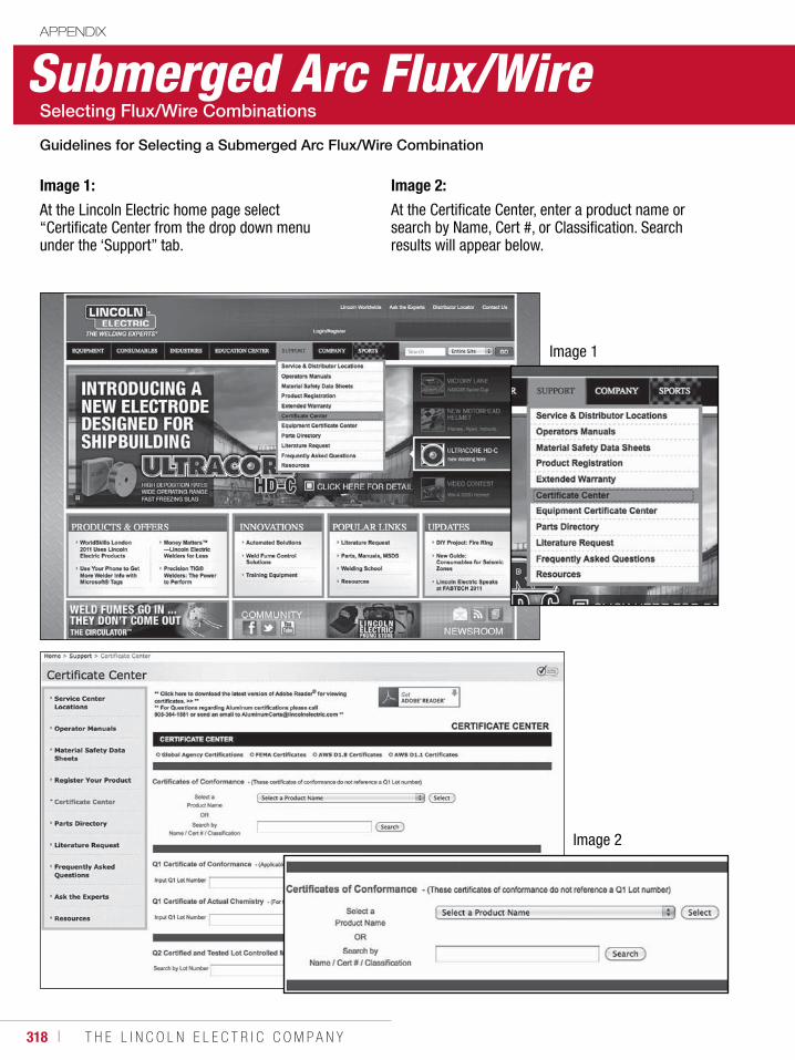
318 ı T H E L I N C O L N E L E C T R I C C O M P A N Y
Submerged Arc Flux/WireAPPENDIX
Image 1:
At the Lincoln Electric home page select “Certificate Center from the drop down menu under the ‘Support” tab.
Image 1
Image 2
Image 2:
At the Certificate Center, enter a product name or search by Name, Cert #, or Classification. Search results will appear below.
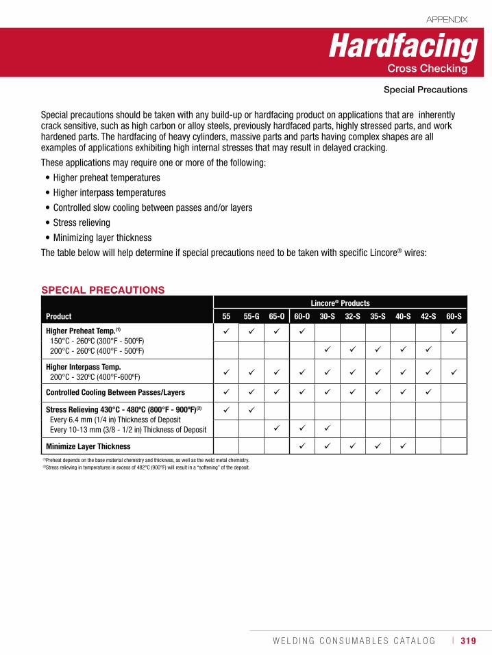
W E L D I N G C O N S U M A B L E S C A T A L O G ı 319
HardfacingAPPENDIX
Special precautions should be taken with any build-up or hardfacing product on applications that are inherently crack sensitive, such as high carbon or alloy steels, previously hardfaced parts, highly stressed parts, and work hardened parts. The hardfacing of heavy cylinders, massive parts and parts having complex shapes are all examples of applications exhibiting high internal stresses that may result in delayed cracking.
These applications may require one or more of the following:
• Higher preheat temperatures
• Higher interpass temperatures
• Controlled slow cooling between passes and/or layers
• Stress relieving
• Minimizing layer thickness
The table below will help determine if special precautions need to be taken with specific Lincore® wires:
SPECIAL PRECAUTIONS
Product
Lincore® Products
55 55-G 65-O 60-O 30-S 32-S 35-S 40-S 42-S 60-S
Higher Preheat Temp.(1)
150°C - 260ºC (300°F - 500ºF)200°C - 260ºC (400°F - 500ºF)
Higher Interpass Temp.200°C - 320ºC (400°F-600ºF)
Controlled Cooling Between Passes/Layers
Stress Relieving 430°C - 480ºC (800°F - 900ºF)(2)
Every 6.4 mm (1/4 in) Thickness of DepositEvery 10-13 mm (3/8 - 1/2 in) Thickness of Deposit
Minimize Layer Thickness(1)Preheat depends on the base material chemistry and thickness, as well as the weld metal chemistry.(2)Stress relieving in temperatures in excess of 482°C (900°F) will result in a “softening” of the deposit.
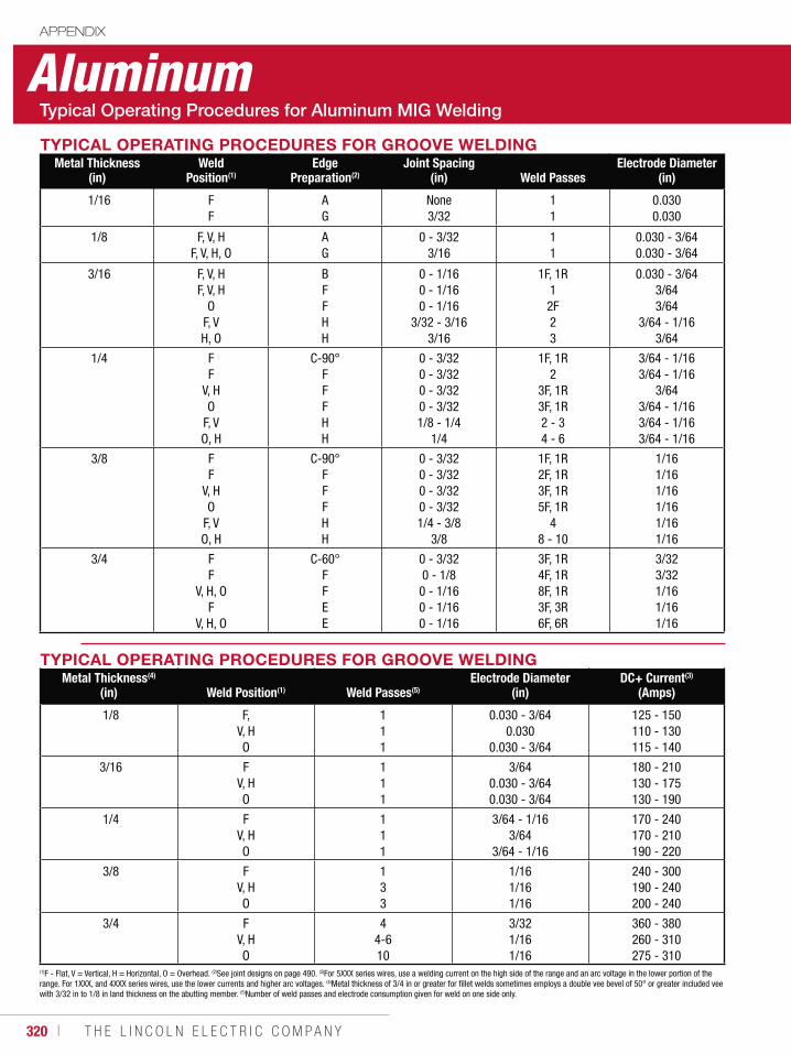
320 ı T H E L I N C O L N E L E C T R I C C O M P A N Y
AluminumAPPENDIX
TYPICAL OPERATING PROCEDURES FOR GROOVE WELDINGMetal Thickness
(in)Weld
Position(1)Edge
Preparation(2)Joint Spacing
(in) Weld PassesElectrode Diameter
(in)
1/16 FF
AG
None3/32
11
0.0300.030
1/8 F, V, HF, V, H, O
AG
0 - 3/323/16
11
0.030 - 3/640.030 - 3/64
3/16 F, V, HF, V, H
OF, VH, O
BFFHH
0 - 1/160 - 1/160 - 1/16
3/32 - 3/163/16
1F, 1R12F23
0.030 - 3/643/643/64
3/64 - 1/163/64
1/4 FF
V, HO
F, VO, H
C-90°FFFHH
0 - 3/320 - 3/320 - 3/320 - 3/321/8 - 1/4
1/4
1F, 1R2
3F, 1R3F, 1R2 - 34 - 6
3/64 - 1/163/64 - 1/16
3/643/64 - 1/163/64 - 1/163/64 - 1/16
3/8 FF
V, HO
F, VO, H
C-90°FFFHH
0 - 3/320 - 3/320 - 3/320 - 3/321/4 - 3/8
3/8
1F, 1R2F, 1R3F, 1R5F, 1R
48 - 10
1/161/161/161/161/161/16
3/4 FF
V, H, OF
V, H, O
C-60°FFEE
0 - 3/320 - 1/8
0 - 1/160 - 1/160 - 1/16
3F, 1R4F, 1R8F, 1R3F, 3R6F, 6R
3/323/321/161/161/16
TYPICAL OPERATING PROCEDURES FOR GROOVE WELDINGMetal Thickness(4)
(in) Weld Position(1) Weld Passes(5)Electrode Diameter
(in)DC+ Current(3)
(Amps)
1/8 F, V, HO
111
0.030 - 3/640.030
0.030 - 3/64
125 - 150110 - 130115 - 140
3/16 FV, HO
111
3/640.030 - 3/640.030 - 3/64
180 - 210130 - 175130 - 190
1/4 FV, HO
111
3/64 - 1/163/64
3/64 - 1/16
170 - 240170 - 210190 - 220
3/8 FV, HO
133
1/161/161/16
240 - 300190 - 240200 - 240
3/4 FV, HO
44-610
3/321/161/16
360 - 380260 - 310275 - 310
(1)F - Flat, V = Vertical, H = Horizontal, O = Overhead. (2)See joint designs on page 490. (3)For 5XXX series wires, use a welding current on the high side of the range and an arc voltage in the lower portion of the range. For 1XXX, and 4XXX series wires, use the lower currents and higher arc voltages. (4)Metal thickness of 3/4 in or greater for fillet welds sometimes employs a double vee bevel of 50° or greater included vee with 3/32 in to 1/8 in land thickness on the abutting member. (5)Number of weld passes and electrode consumption given for weld on one side only.
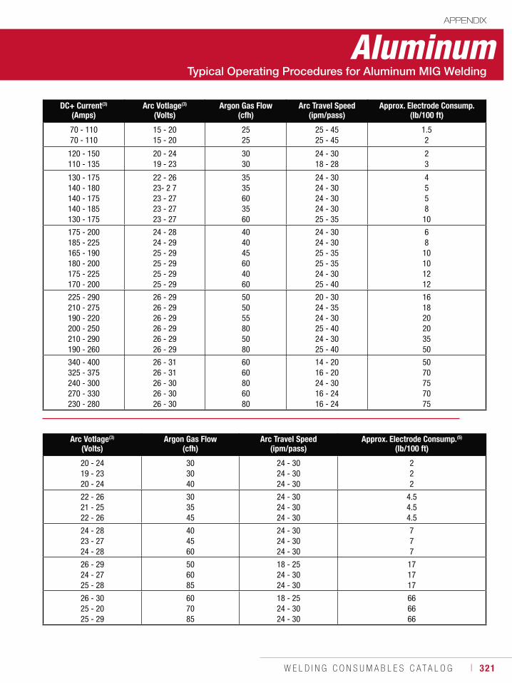
W E L D I N G C O N S U M A B L E S C A T A L O G ı 321
DC+ Current(3)
(Amps)Arc Votlage(3)
(Volts)Argon Gas Flow
(cfh)Arc Travel Speed
(ipm/pass)Approx. Electrode Consump.
(lb/100 ft)
70 - 11070 - 110
15 - 2015 - 20
2525
25 - 4525 - 45
1.52
120 - 150110 - 135
20 - 2419 - 23
3030
24 - 3018 - 28
23
130 - 175140 - 180140 - 175140 - 185130 - 175
22 - 2623- 2 723 - 2723 - 2723 - 27
3535603560
24 - 3024 - 3024 - 3024 - 3025 - 35
4558
10
175 - 200185 - 225165 - 190180 - 200175 - 225170 - 200
24 - 2824 - 2925 - 2925 - 2925 - 2925 - 29
404045604060
24 - 3024 - 3025 - 3525 - 3524 - 3025 - 40
68
10101212
225 - 290210 - 275190 - 220200 - 250210 - 290190 - 260
26 - 2926 - 2926 - 2926 - 2926 - 2926 - 29
505055805080
20 - 3024 - 3524 - 3025 - 4024 - 3025 - 40
161820203550
340 - 400325 - 375240 - 300270 - 330230 - 280
26 - 3126 - 3126 - 3026 - 3026 - 30
6060806080
14 - 2016 - 2024 - 3016 - 2416 - 24
5070757075
AluminumAPPENDIX
Arc Votlage(3)
(Volts)Argon Gas Flow
(cfh)Arc Travel Speed
(ipm/pass)Approx. Electrode Consump.(5)
(lb/100 ft)
20 - 2419 - 2320 - 24
303040
24 - 3024 - 3024 - 30
222
22 - 2621 - 2522 - 26
303545
24 - 3024 - 3024 - 30
4.54.54.5
24 - 2823 - 2724 - 28
404560
24 - 3024 - 3024 - 30
777
26 - 2924 - 2725 - 28
506085
18 - 2524 - 3024 - 30
171717
26 - 3025 - 2025 - 29
607085
18 - 2524 - 3024 - 30
666666

322 ı T H E L I N C O L N E L E C T R I C C O M P A N Y
AluminumAPPENDIX
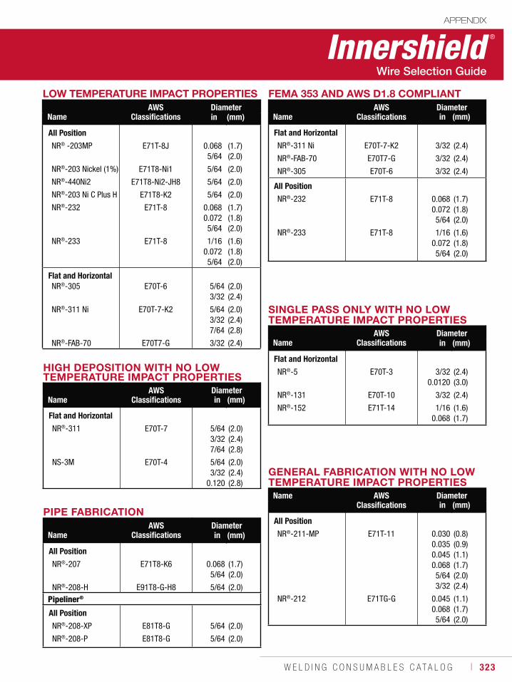
W E L D I N G C O N S U M A B L E S C A T A L O G ı 323
Innershield ®
APPENDIX
LOW TEMPERATURE IMPACT PROPERTIES
NameAWS
ClassificationsDiameterin (mm)
All Position
NR® -203MP
NR®-203 Nickel (1%)
NR®-440Ni2
NR®-203 Ni C Plus H
NR®-232
NR®-233
E71T-8J
E71T8-Ni1
E71T8-Ni2-JH8
E71T8-K2
E71T-8
E71T-8
0.068 5/64
5/64
5/64
5/64
0.068 0.072 5/64
1/16 0.072 5/64
(1.7) (2.0)
(2.0)
(2.0)
(2.0)
(1.7) (1.8) (2.0)
(1.6) (1.8) (2.0)
Flat and HorizontalNR®-305
NR®-311 Ni
NR®-FAB-70
E70T-6
E70T-7-K2
E70T7-G
5/64 3/32
5/64 3/32 7/64
3/32
(2.0) (2.4)
(2.0) (2.4) (2.8)
(2.4)
HIGH DEPOSITION WITH NO LOW TEMPERATURE IMPACT PROPERTIES
NameAWS
ClassificationsDiameterin (mm)
Flat and Horizontal
NR®-311
NS-3M
E70T-7
E70T-4
5/64 3/32 7/64
5/64 3/32
0.120
(2.0) (2.4) (2.8)
(2.0) (2.4) (2.8)
SINGLE PASS ONLY WITH NO LOW TEMPERATURE IMPACT PROPERTIES
NameAWS
ClassificationsDiameterin (mm)
Flat and Horizontal
NR®-5
NR®-131
NR®-152
E70T-3
E70T-10
E71T-14
3/32 0.0120
3/32
1/16 0.068
(2.4) (3.0)
(2.4)
(1.6) (1.7)
PIPE FABRICATION
NameAWS
ClassificationsDiameterin (mm)
All Position
NR®-207
NR®-208-H
E71T8-K6
E91T8-G-H8
0.068 5/64
5/64
(1.7) (2.0)
(2.0)Pipeliner®
All Position
NR®-208-XP
NR®-208-P
E81T8-G
E81T8-G
5/64
5/64
(2.0)
(2.0)
GENERAL FABRICATION WITH NO LOW TEMPERATURE IMPACT PROPERTIES
Name AWS Classifications
Diameterin (mm)
All Position
NR®-211-MP
NR®-212
E71T-11
E71TG-G
0.030 0.035 0.045 0.068 5/64 3/32
0.045 0.068 5/64
(0.8) (0.9) (1.1) (1.7) (2.0) (2.4)
(1.1) (1.7) (2.0)
FEMA 353 AND AWS D1.8 COMPLIANT
NameAWS
ClassificationsDiameterin (mm)
Flat and Horizontal
NR®-311 Ni
NR®-FAB-70
NR®-305
E70T-7-K2
E70T7-G
E70T-6
3/32
3/32
3/32
(2.4)
(2.4)
(2.4)
All Position
NR®-232
NR®-233
E71T-8
E71T-8
0.068 0.072 5/64
1/16 0.072 5/64
(1.7) (1.8) (2.0)
(1.6) (1.8) (2.0)
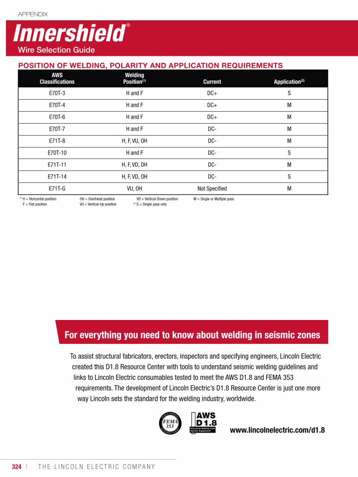
324 ı T H E L I N C O L N E L E C T R I C C O M P A N Y
POSITION OF WELDING, POLARITY AND APPLICATION REQUIREMENTSAWS
ClassificationsWelding
Position(1) Current Application(2)
E70T-3 H and F DC+ S
E70T-4 H and F DC+ M
E70T-6 H and F DC+ M
E70T-7 H and F DC- M
E71T-8 H, F, VU, OH DC- M
E70T-10 H and F DC- S
E71T-11 H, F, VD, OH DC- M
E71T-14 H, F, VD, OH DC- S
E71T-G VU, OH Not Specified M(1) H = Horizontal position
F = Flat position OH = Overhead position VU = Vertical-Up position
VD = Vertical-Down position(2) S = Single pass only
M = Single or Multiple pass
Innershield®
APPENDIX
Structural Welding Code Seismic Supplement
For everything you need to know about welding in seismic zones
To assist structural fabricators, erectors, inspectors and specifying engineers, Lincoln Electric
created this D1.8 Resource Center with tools to understand seismic welding guidelines and
links to Lincoln Electric consumables tested to meet the AWS D1.8 and FEMA 353
requirements. The development of Lincoln Electric’s D1.8 Resource Center is just one more
way Lincoln sets the standard for the welding industry, worldwide.
www.lincolnelectric.com/d1.8
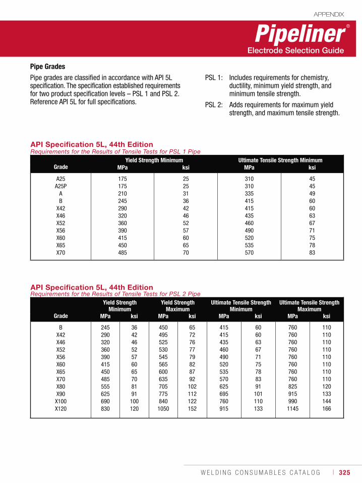
W E L D I N G C O N S U M A B L E S C A T A L O G ı 325
Pipeliner ®
APPENDIX
API Specification 5L, 44th EditionRequirements for the Results of Tensile Tests for PSL 1 Pipe
GradeYield Strength Minimum Ultimate Tensile Strength Minimum
MPa ksi MPa ksi
A25A25P
AB
X42X46X52X56X60X65X70
175175210245290320360390415450485
2525313642465257606570
310310335415415435460490520535570
4545496060636771757883
API Specification 5L, 44th EditionRequirements for the Results of Tensile Tests for PSL 2 Pipe
Grade
Yield StrengthMinimum
Yield StrengthMaximum
Ultimate Tensile StrengthMinimum
Ultimate Tensile StrengthMaximum
MPa ksi MPa ksi MPa ksi MPa ksi
BX42X46X52X56X60X65X70X80X90
X100X120
245290320360390415450485555625690830
36424652576065708191
100120
450495525530545565600635705775840
1050
6572767779828792
102112122152
415415435460490520535570625695760915
606063677175788391
101110133
760760760760760760760760825915990
1145
110110110110110110110110120133144166
Pipe Grades
Pipe grades are classified in accordance with API 5L specification. The specification established requirementsfor two product specification levels – PSL 1 and PSL 2. Reference API 5L for full specifications.
PSL 1: Includes requirements for chemistry, ductility, minimum yield strength, and minimum tensile strength.
PSL 2: Adds requirements for maximum yield strength, and maximum tensile strength.
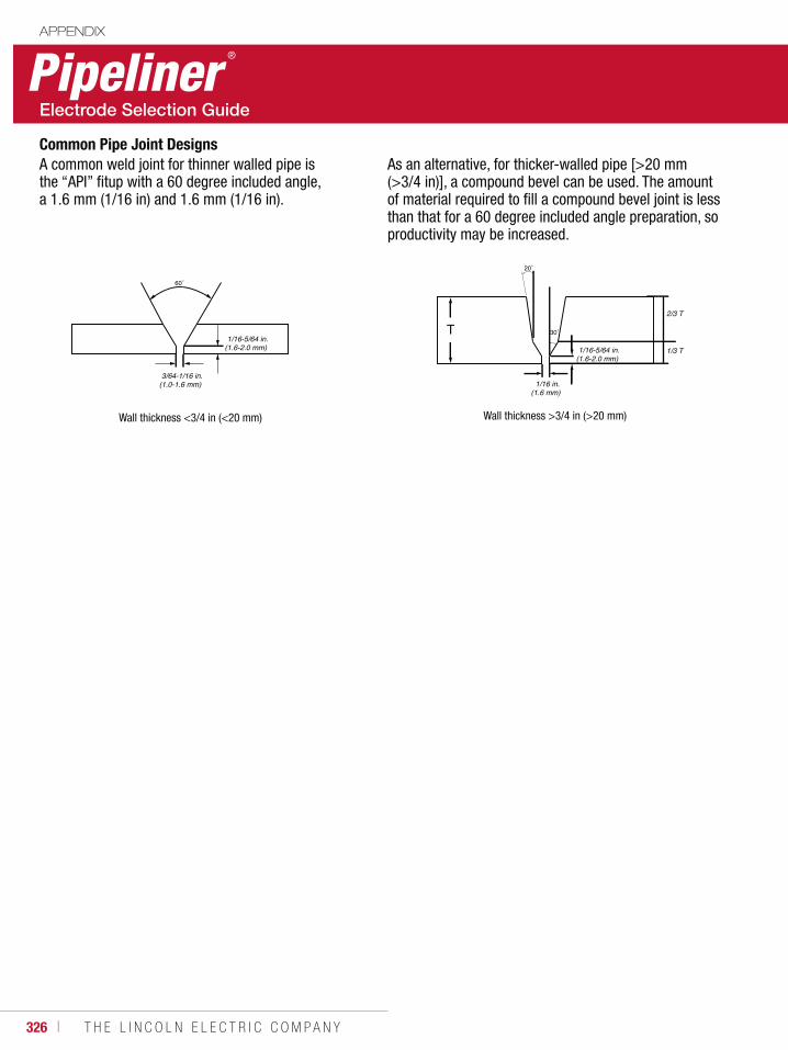
326 ı T H E L I N C O L N E L E C T R I C C O M P A N Y
Pipeliner®
APPENDIX
Common Pipe Joint Designs
60˚
3/64-1/16 in.(1.0-1.6 mm)
1/16-5/64 in.(1.6-2.0 mm)
1/16 in.(1.6 mm)
1/3 T
2/3 T
1/16-5/64 in.(1.6-2.0 mm)
20˚
30˚T
A common weld joint for thinner walled pipe is the “API” fitup with a 60 degree included angle, a 1.6 mm (1/16 in) and 1.6 mm (1/16 in).
Wall thickness <3/4 in (<20 mm) Wall thickness >3/4 in (>20 mm)
As an alternative, for thicker-walled pipe [>20 mm (>3/4 in)], a compound bevel can be used. The amount of material required to fill a compound bevel joint is less than that for a 60 degree included angle preparation, so productivity may be increased.
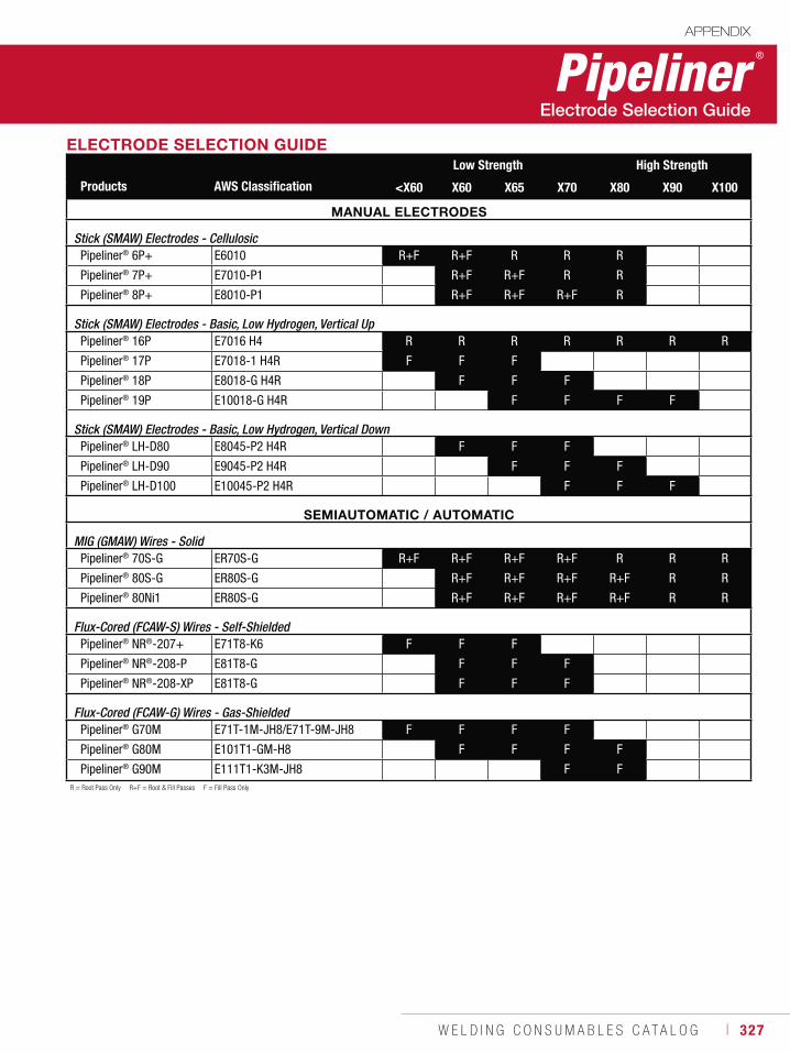
W E L D I N G C O N S U M A B L E S C A T A L O G ı 327
Pipeliner®
APPENDIX
ELECTRODE SELECTION GUIDE
Products AWS Classification
Low Strength High Strength
<X60 X60 X65 X70 X80 X90 X100
MANUAL ELECTRODES
Stick (SMAW) Electrodes - CellulosicPipeliner® 6P+ E6010 R+F R+F R R R
Pipeliner® 7P+ E7010-P1 R+F R+F R R
Pipeliner® 8P+ E8010-P1 R+F R+F R+F R
Stick (SMAW) Electrodes - Basic, Low Hydrogen, Vertical UpPipeliner® 16P E7016 H4 R R R R R R R
Pipeliner® 17P E7018-1 H4R F F F
Pipeliner® 18P E8018-G H4R F F F
Pipeliner® 19P E10018-G H4R F F F F
Stick (SMAW) Electrodes - Basic, Low Hydrogen, Vertical DownPipeliner® LH-D80 E8045-P2 H4R F F F
Pipeliner® LH-D90 E9045-P2 H4R F F F
Pipeliner® LH-D100 E10045-P2 H4R F F F
SEMIAUTOMATIC / AUTOMATIC
MIG (GMAW) Wires - SolidPipeliner® 70S-G ER70S-G R+F R+F R+F R+F R R R
Pipeliner® 80S-G ER80S-G R+F R+F R+F R+F R R
Pipeliner® 80Ni1 ER80S-G R+F R+F R+F R+F R R
Flux-Cored (FCAW-S) Wires - Self-ShieldedPipeliner® NR®-207+ E71T8-K6 F F F
Pipeliner® NR®-208-P E81T8-G F F F
Pipeliner® NR®-208-XP E81T8-G F F F
Flux-Cored (FCAW-G) Wires - Gas-ShieldedPipeliner® G70M E71T-1M-JH8/E71T-9M-JH8 F F F F
Pipeliner® G80M E101T1-GM-H8 F F F F
Pipeliner® G90M E111T1-K3M-JH8 F FR = Root Pass Only R+F = Root & Fill Passes F = Fill Pass Only
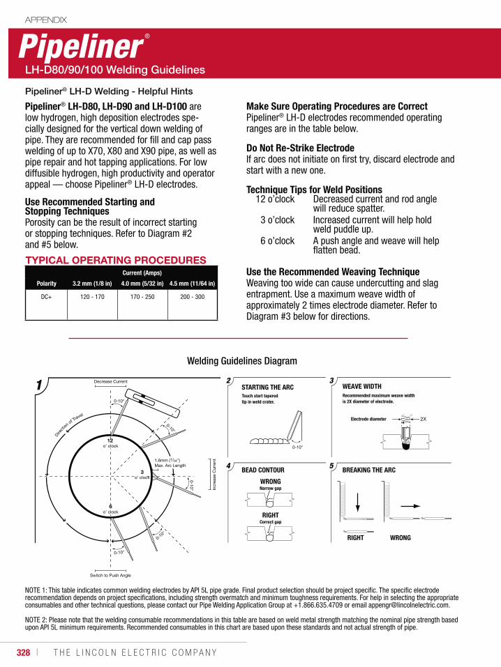
328 ı T H E L I N C O L N E L E C T R I C C O M P A N Y
Pipeliner ®
APPENDIX
Pipeliner® LH-D80, LH-D90 and LH-D100 are low hydrogen, high deposition electrodes spe-cially designed for the vertical down welding of pipe. They are recommended for fill and cap pass welding of up to X70, X80 and X90 pipe, as well as pipe repair and hot tapping applications. For low diffusible hydrogen, high productivity and operator appeal — choose Pipeliner® LH-D electrodes.
Use Recommended Starting and Stopping Techniques Porosity can be the result of incorrect starting or stopping techniques. Refer to Diagram #2 and #5 below.
TYPICAL OPERATING PROCEDURESCurrent (Amps)
Polarity 3.2 mm (1/8 in) 4.0 mm (5/32 in) 4.5 mm (11/64 in)
DC+ 120 - 170 170 - 250 200 - 300
BREAKING THE ARCBEAD CONTOUR
STARTING THE ARC32
54
Recommended maximum weave widthis 2X diameter of electrode.
Electrode diameter
WRONGNarrow gap
Touch start taperedtip in weld crater.0-10°
0-10°
0-10°
12 o’ clock
3o’ clock
6o’ clock
0-10°
0-10°
1.6mm (1⁄16”) Max. Arc Length
Direct
ion of Travel
Incr
ease
Cur
rent
Decrease Current
RIGHTCorrect gap
WEAVE WIDTH
RIGHT WRONG
0-10°
Switch to Push Angle
Welding Guidelines Diagram
NOTE 1: This table indicates common welding electrodes by API 5L pipe grade. Final product selection should be project specific. The specific electrode recommendation depends on project specifications, including strength overmatch and minimum toughness requirements. For help in selecting the appropriate consumables and other technical questions, please contact our Pipe Welding Application Group at +1.866.635.4709 or email [email protected].
NOTE 2: Please note that the welding consumable recommendations in this table are based on weld metal strength matching the nominal pipe strength based upon API 5L minimum requirements. Recommended consumables in this chart are based upon these standards and not actual strength of pipe.
Make Sure Operating Procedures are Correct Pipeliner® LH-D electrodes recommended operating ranges are in the table below.
Do Not Re-Strike Electrode If arc does not initiate on first try, discard electrode and start with a new one.
Technique Tips for Weld Positions12 o’clock Decreased current and rod angle will reduce spatter. 3 o’clock Increased current will help hold weld puddle up. 6 o’clock A push angle and weave will help flatten bead.
Use the Recommended Weaving TechniqueWeaving too wide can cause undercutting and slag entrapment. Use a maximum weave width of approximately 2 times electrode diameter. Refer to Diagram #3 below for directions.
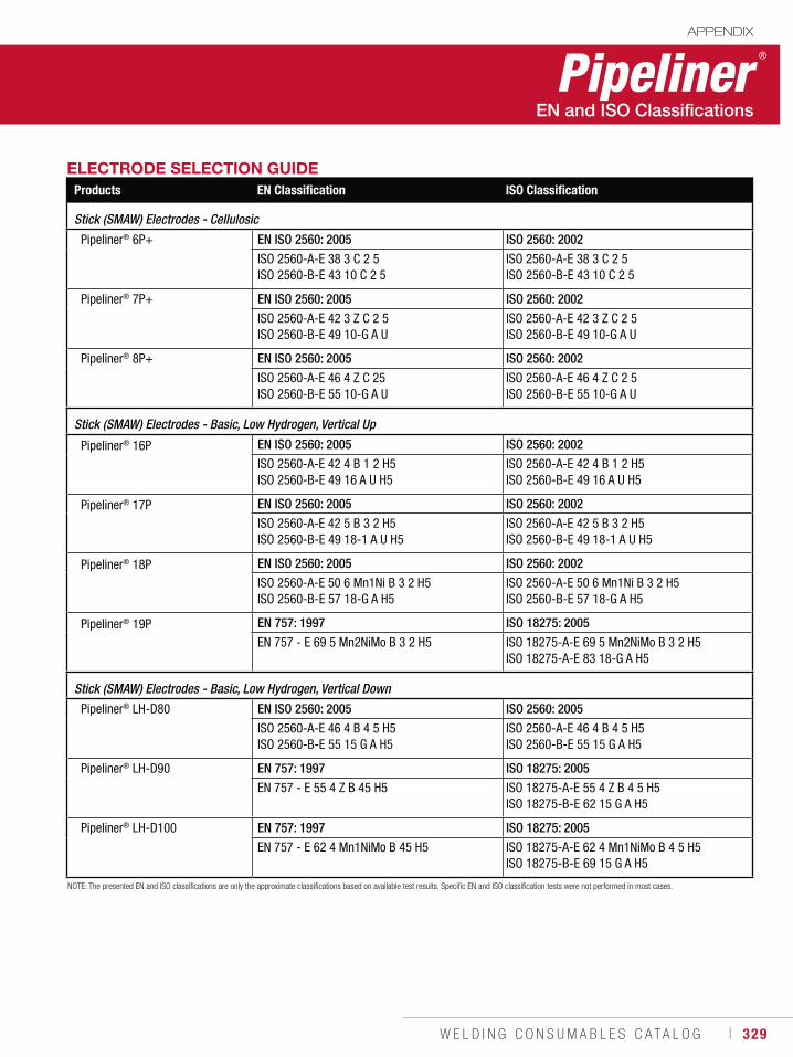
W E L D I N G C O N S U M A B L E S C A T A L O G ı 329
Pipeliner®
APPENDIX
ELECTRODE SELECTION GUIDEProducts EN Classification ISO Classification
Stick (SMAW) Electrodes - Cellulosic
Pipeliner® 6P+ EN ISO 2560: 2005 ISO 2560: 2002
ISO 2560-A-E 38 3 C 2 5ISO 2560-B-E 43 10 C 2 5
ISO 2560-A-E 38 3 C 2 5ISO 2560-B-E 43 10 C 2 5
Pipeliner® 7P+ EN ISO 2560: 2005 ISO 2560: 2002
ISO 2560-A-E 42 3 Z C 2 5ISO 2560-B-E 49 10-G A U
ISO 2560-A-E 42 3 Z C 2 5ISO 2560-B-E 49 10-G A U
Pipeliner® 8P+ EN ISO 2560: 2005 ISO 2560: 2002
ISO 2560-A-E 46 4 Z C 25ISO 2560-B-E 55 10-G A U
ISO 2560-A-E 46 4 Z C 2 5ISO 2560-B-E 55 10-G A U
Stick (SMAW) Electrodes - Basic, Low Hydrogen, Vertical Up
Pipeliner® 16P EN ISO 2560: 2005 ISO 2560: 2002
ISO 2560-A-E 42 4 B 1 2 H5ISO 2560-B-E 49 16 A U H5
ISO 2560-A-E 42 4 B 1 2 H5ISO 2560-B-E 49 16 A U H5
Pipeliner® 17P EN ISO 2560: 2005 ISO 2560: 2002
ISO 2560-A-E 42 5 B 3 2 H5ISO 2560-B-E 49 18-1 A U H5
ISO 2560-A-E 42 5 B 3 2 H5ISO 2560-B-E 49 18-1 A U H5
Pipeliner® 18P EN ISO 2560: 2005 ISO 2560: 2002
ISO 2560-A-E 50 6 Mn1Ni B 3 2 H5ISO 2560-B-E 57 18-G A H5
ISO 2560-A-E 50 6 Mn1Ni B 3 2 H5ISO 2560-B-E 57 18-G A H5
Pipeliner® 19P EN 757: 1997 ISO 18275: 2005
EN 757 - E 69 5 Mn2NiMo B 3 2 H5 ISO 18275-A-E 69 5 Mn2NiMo B 3 2 H5ISO 18275-A-E 83 18-G A H5
Stick (SMAW) Electrodes - Basic, Low Hydrogen, Vertical Down
Pipeliner® LH-D80 EN ISO 2560: 2005 ISO 2560: 2005
ISO 2560-A-E 46 4 B 4 5 H5ISO 2560-B-E 55 15 G A H5
ISO 2560-A-E 46 4 B 4 5 H5ISO 2560-B-E 55 15 G A H5
Pipeliner® LH-D90 EN 757: 1997 ISO 18275: 2005
EN 757 - E 55 4 Z B 45 H5 ISO 18275-A-E 55 4 Z B 4 5 H5ISO 18275-B-E 62 15 G A H5
Pipeliner® LH-D100 EN 757: 1997 ISO 18275: 2005
EN 757 - E 62 4 Mn1NiMo B 45 H5 ISO 18275-A-E 62 4 Mn1NiMo B 4 5 H5ISO 18275-B-E 69 15 G A H5
NOTE: The presented EN and ISO classifications are only the approximate classifications based on available test results. Specific EN and ISO classification tests were not performed in most cases.
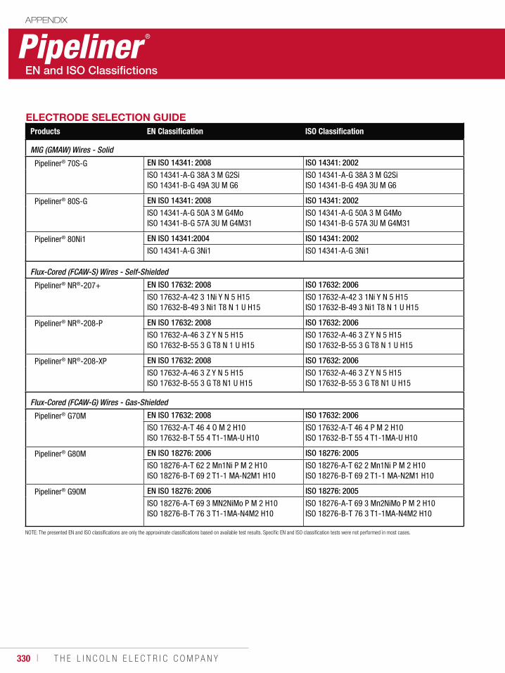
330 ı T H E L I N C O L N E L E C T R I C C O M P A N Y
APPENDIX
ELECTRODE SELECTION GUIDEProducts EN Classification ISO Classification
MIG (GMAW) Wires - Solid
Pipeliner® 70S-G EN ISO 14341: 2008 ISO 14341: 2002
ISO 14341-A-G 38A 3 M G2SiISO 14341-B-G 49A 3U M G6
ISO 14341-A-G 38A 3 M G2SiISO 14341-B-G 49A 3U M G6
Pipeliner® 80S-G EN ISO 14341: 2008 ISO 14341: 2002
ISO 14341-A-G 50A 3 M G4MoISO 14341-B-G 57A 3U M G4M31
ISO 14341-A-G 50A 3 M G4MoISO 14341-B-G 57A 3U M G4M31
Pipeliner® 80Ni1 EN ISO 14341:2004 ISO 14341: 2002
ISO 14341-A-G 3Ni1 ISO 14341-A-G 3Ni1
Flux-Cored (FCAW-S) Wires - Self-Shielded
Pipeliner® NR®-207+ EN ISO 17632: 2008 ISO 17632: 2006
ISO 17632-A-42 3 1Ni Y N 5 H15ISO 17632-B-49 3 Ni1 T8 N 1 U H15
ISO 17632-A-42 3 1Ni Y N 5 H15ISO 17632-B-49 3 Ni1 T8 N 1 U H15
Pipeliner® NR®-208-P EN ISO 17632: 2008 ISO 17632: 2006
ISO 17632-A-46 3 Z Y N 5 H15ISO 17632-B-55 3 G T8 N 1 U H15
ISO 17632-A-46 3 Z Y N 5 H15ISO 17632-B-55 3 G T8 N 1 U H15
Pipeliner® NR®-208-XP EN ISO 17632: 2008 ISO 17632: 2006
ISO 17632-A-46 3 Z Y N 5 H15ISO 17632-B-55 3 G T8 N1 U H15
ISO 17632-A-46 3 Z Y N 5 H15ISO 17632-B-55 3 G T8 N1 U H15
Flux-Cored (FCAW-G) Wires - Gas-Shielded
Pipeliner® G70M EN ISO 17632: 2008 ISO 17632: 2006
ISO 17632-A-T 46 4 O M 2 H10ISO 17632-B-T 55 4 T1-1MA-U H10
ISO 17632-A-T 46 4 P M 2 H10ISO 17632-B-T 55 4 T1-1MA-U H10
Pipeliner® G80M EN ISO 18276: 2006 ISO 18276: 2005
ISO 18276-A-T 62 2 Mn1Ni P M 2 H10ISO 18276-B-T 69 2 T1-1 MA-N2M1 H10
ISO 18276-A-T 62 2 Mn1Ni P M 2 H10ISO 18276-B-T 69 2 T1-1 MA-N2M1 H10
Pipeliner® G90M EN ISO 18276: 2006 ISO 18276: 2005
ISO 18276-A-T 69 3 MN2NiMo P M 2 H10ISO 18276-B-T 76 3 T1-1MA-N4M2 H10
ISO 18276-A-T 69 3 Mn2NiMo P M 2 H10ISO 18276-B-T 76 3 T1-1MA-N4M2 H10
NOTE: The presented EN and ISO classifications are only the approximate classifications based on available test results. Specific EN and ISO classification tests were not performed in most cases.
Pipeliner ®
W E L D I N G C O N S U M A B L E S C A T A L O G ı 331
Agency ApprovalsAPPENDIX
The notes and codes listed below are also repeated throughout the catalog where applicable.
• American Bureau of Shipping (ABS) approvals are issued subject to the Bureau’s Rule requirement for Materials and Welding Part 2. Tests are conducted in the company’s plant, under supervision of an ABS surveyor to determine if electrodes conform to ABS grades or AWS specifications previously judged satisfactory by ABS for welding vessels. The Bureau publishes a list of approved electrodes giving their class and approved operating positions for each size. Sometimes, where there is no approved specification, approval may be given on the basis that each individual shipyard or contractor will qualify the procedure and electrode subject to Part 2, Section 3, paragraph 2/3C.3.2.c.
• American Society of Mechanical Engineers (ASME) has issued specifications covering construction of nuclear facilities. Each lot of welding consumables to be used must be individually tested to ASME SFA specifications.
• American Welding Society (AWS) specifications and classifications are established by the Society to provide standards for different types of electrodes throughout the industry. AWS does not test or approve any electrodes. The manufacturer certifies that their electrode conforms to a certain class.
• Canadian Welding Bureau (CWB) approvals are based on tests witnessed by a CWB representative. Approvals listed in this booklet are for products manufactured in the USA. Products manufactured in Canada are approved separately. In general, CWB specifications are similar to AWS specifications. Copies of approvals are maintained in Cleveland and are available upon request.
• Lloyd’s Register (LR), Det Norske Veritas (DNV), Germanischer Lloyd (GL), Bureau Veritas (BV), Controlas, and Nippon Kaiji Kyokai (NKK) issue approvals for electrodes used worldwide in shipbuilding, offshore structures and pressure vessels. Products approved under the rules of these classification societies require annual requalification under the supervision of their surveyors.
• TÜV (TUV) is a German agency very similar to ASME. Projects manufactured under TUV rules must be welded with consumable approved by TUV. Initial approvals are obtained based on testing completed under TUV supervision. Approvals are maintained subject to Quality Assurance audits completed every two years.
• Deutche Bahn (DB) is the approval agency for German railroads. Approvals are based on tests specified by DB, and witnessed by an authorized third party.
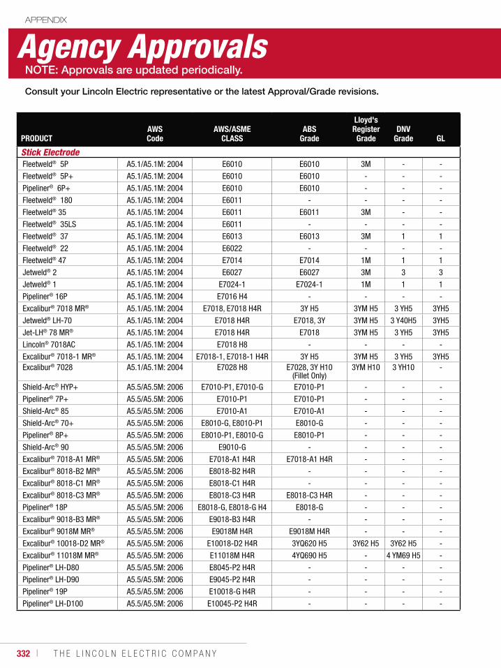
332 ı T H E L I N C O L N E L E C T R I C C O M P A N Y
PRODUCTAWS Code
AWS/ASME CLASS
ABS Grade
Lloyd's Register
GradeDNV
Grade GL
Stick ElectrodeFleetweld® 5P A5.1/A5.1M: 2004 E6010 E6010 3M - -
Fleetweld® 5P+ A5.1/A5.1M: 2004 E6010 E6010 - - -
Pipeliner® 6P+ A5.1/A5.1M: 2004 E6010 E6010 - - -
Fleetweld® 180 A5.1/A5.1M: 2004 E6011 - - - -
Fleetweld® 35 A5.1/A5.1M: 2004 E6011 E6011 3M - -
Fleetweld® 35LS A5.1/A5.1M: 2004 E6011 - - - -
Fleetweld® 37 A5.1/A5.1M: 2004 E6013 E6013 3M 1 1
Fleetweld® 22 A5.1/A5.1M: 2004 E6022 - - - -
Fleetweld® 47 A5.1/A5.1M: 2004 E7014 E7014 1M 1 1
Jetweld® 2 A5.1/A5.1M: 2004 E6027 E6027 3M 3 3
Jetweld® 1 A5.1/A5.1M: 2004 E7024-1 E7024-1 1M 1 1
Pipeliner® 16P A5.1/A5.1M: 2004 E7016 H4 - - - -
Excalibur® 7018 MR® A5.1/A5.1M: 2004 E7018, E7018 H4R 3Y H5 3YM H5 3 YH5 3YH5
Jetweld® LH-70 A5.1/A5.1M: 2004 E7018 H4R E7018, 3Y 3YM H5 3 Y40H5 3YH5
Jet-LH® 78 MR® A5.1/A5.1M: 2004 E7018 H4R E7018 3YM H5 3 YH5 3YH5
Lincoln® 7018AC A5.1/A5.1M: 2004 E7018 H8 - - - -
Excalibur® 7018-1 MR® A5.1/A5.1M: 2004 E7018-1, E7018-1 H4R 3Y H5 3YM H5 3 YH5 3YH5Excalibur® 7028 A5.1/A5.1M: 2004 E7028 H8 E7028, 3Y H10
(Fillet Only)3YM H10 3 YH10 -
Shield-Arc® HYP+ A5.5/A5.5M: 2006 E7010-P1, E7010-G E7010-P1 - - -
Pipeliner® 7P+ A5.5/A5.5M: 2006 E7010-P1 E7010-P1 - - -
Shield-Arc® 85 A5.5/A5.5M: 2006 E7010-A1 E7010-A1 - - -
Shield-Arc® 70+ A5.5/A5.5M: 2006 E8010-G, E8010-P1 E8010-G - - -
Pipeliner® 8P+ A5.5/A5.5M: 2006 E8010-P1, E8010-G E8010-P1 - - -
Shield-Arc® 90 A5.5/A5.5M: 2006 E9010-G - - - -
Excalibur® 7018-A1 MR® A5.5/A5.5M: 2006 E7018-A1 H4R E7018-A1 H4R - - -
Excalibur® 8018-B2 MR® A5.5/A5.5M: 2006 E8018-B2 H4R - - - -
Excalibur® 8018-C1 MR® A5.5/A5.5M: 2006 E8018-C1 H4R - - - -
Excalibur® 8018-C3 MR® A5.5/A5.5M: 2006 E8018-C3 H4R E8018-C3 H4R - - -
Pipeliner® 18P A5.5/A5.5M: 2006 E8018-G, E8018-G H4 E8018-G - - -
Excalibur® 9018-B3 MR® A5.5/A5.5M: 2006 E9018-B3 H4R - - - -
Excalibur® 9018M MR® A5.5/A5.5M: 2006 E9018M H4R E9018M H4R - - -
Excalibur® 10018-D2 MR® A5.5/A5.5M: 2006 E10018-D2 H4R 3YQ620 H5 3Y62 H5 3Y62 H5 -
Excalibur® 11018M MR® A5.5/A5.5M: 2006 E11018M H4R 4YQ690 H5 - 4 YM69 H5 -
Pipeliner® LH-D80 A5.5/A5.5M: 2006 E8045-P2 H4R - - - -
Pipeliner® LH-D90 A5.5/A5.5M: 2006 E9045-P2 H4R - - - -
Pipeliner® 19P A5.5/A5.5M: 2006 E10018-G H4R - - - -
Pipeliner® LH-D100 A5.5/A5.5M: 2006 E10045-P2 H4R - - - -
Agency ApprovalsAPPENDIX
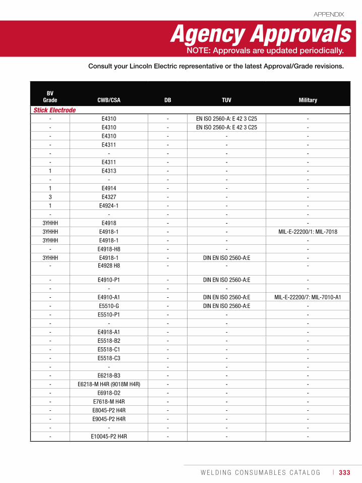
W E L D I N G C O N S U M A B L E S C A T A L O G ı 333
BV Grade CWB/CSA DB TUV Military
Stick Electrode- E4310 - EN ISO 2560-A: E 42 3 C25 -
- E4310 - EN ISO 2560-A: E 42 3 C25 -
- E4310 - - -
- E4311 - - -
- - - - -
- E4311 - - -
1 E4313 - - -
- - - - -
1 E4914 - - -
3 E4327 - - -
1 E4924-1 - - -
- - - - -
3YHHH E4918 - - -
3YHHH E4918-1 - - MIL-E-22200/1: MIL-7018
3YHHH E4918-1 - - -
- E4918-H8 - - -
3YHHH E4918-1 - DIN EN ISO 2560-A:E -- E4928 H8 - - -
- E4910-P1 - DIN EN ISO 2560-A:E -
- - - - -
- E4910-A1 - DIN EN ISO 2560-A:E MIL-E-22200/7: MIL-7010-A1
- E5510-G - DIN EN ISO 2560-A:E -
- E5510-P1 - - -
- - - - -
- E4918-A1 - - -
- E5518-B2 - - -
- E5518-C1 - - -
- E5518-C3 - - -
- - - - -
- E6218-B3 - - -
- E6218-M H4R (9018M H4R) - - -
- E6918-D2 - - -
- E7618-M H4R - - -
- E8045-P2 H4R - - -
- E9045-P2 H4R - - -
- - - - -
- E10045-P2 H4R - - -
Agency ApprovalsAPPENDIX
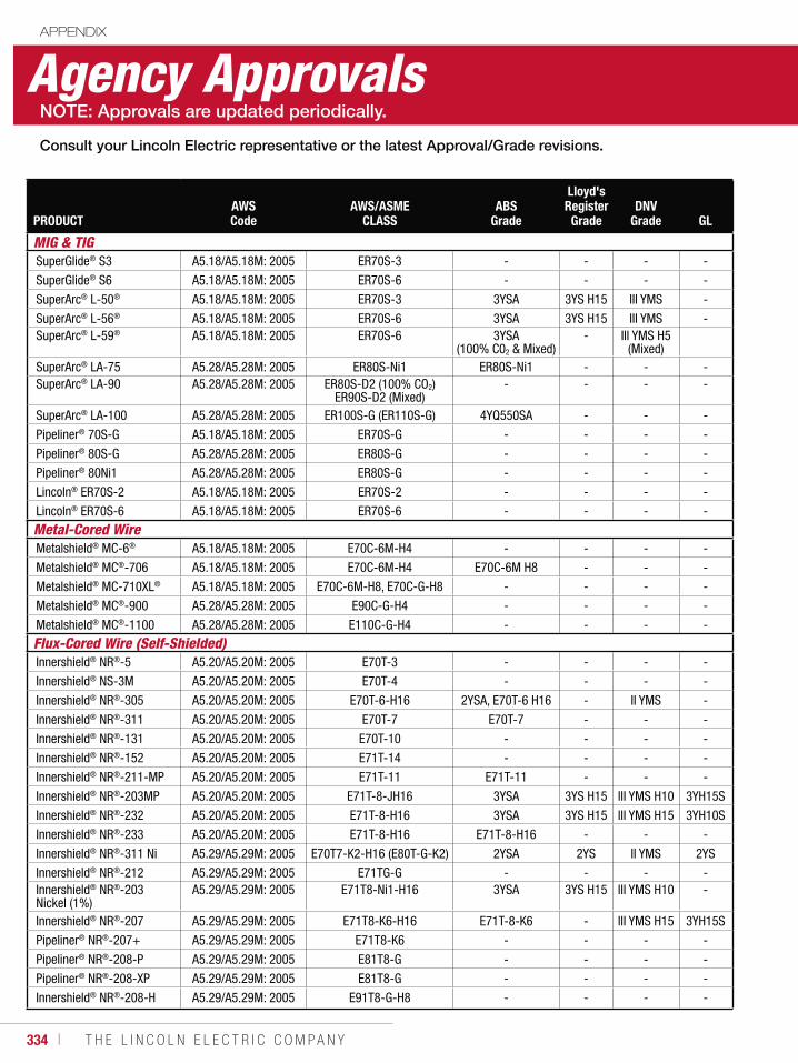
334 ı T H E L I N C O L N E L E C T R I C C O M P A N Y
PRODUCTAWS Code
AWS/ASME CLASS
ABS Grade
Lloyd's Register
GradeDNV
Grade GL
MIG & TIG SuperGlide® S3 A5.18/A5.18M: 2005 ER70S-3 - - - -
SuperGlide® S6 A5.18/A5.18M: 2005 ER70S-6 - - - -
SuperArc® L-50® A5.18/A5.18M: 2005 ER70S-3 3YSA 3YS H15 III YMS -
SuperArc® L-56® A5.18/A5.18M: 2005 ER70S-6 3YSA 3YS H15 III YMS -SuperArc® L-59® A5.18/A5.18M: 2005 ER70S-6 3YSA
(100% C02 & Mixed)- III YMS H5
(Mixed)SuperArc® LA-75 A5.28/A5.28M: 2005 ER80S-Ni1 ER80S-Ni1 - - -SuperArc® LA-90 A5.28/A5.28M: 2005 ER80S-D2 (100% CO2)
ER90S-D2 (Mixed)- - - -
SuperArc® LA-100 A5.28/A5.28M: 2005 ER100S-G (ER110S-G) 4YQ550SA - - -
Pipeliner® 70S-G A5.18/A5.18M: 2005 ER70S-G - - - -
Pipeliner® 80S-G A5.28/A5.28M: 2005 ER80S-G - - - -
Pipeliner® 80Ni1 A5.28/A5.28M: 2005 ER80S-G - - - -
Lincoln® ER70S-2 A5.18/A5.18M: 2005 ER70S-2 - - - -
Lincoln® ER70S-6 A5.18/A5.18M: 2005 ER70S-6 - - - -
Metal-Cored Wire Metalshield® MC-6® A5.18/A5.18M: 2005 E70C-6M-H4 - - - -
Metalshield® MC®-706 A5.18/A5.18M: 2005 E70C-6M-H4 E70C-6M H8 - - -
Metalshield® MC-710XL® A5.18/A5.18M: 2005 E70C-6M-H8, E70C-G-H8 - - - -
Metalshield® MC®-900 A5.28/A5.28M: 2005 E90C-G-H4 - - - -
Metalshield® MC®-1100 A5.28/A5.28M: 2005 E110C-G-H4 - - - -
Flux-Cored Wire (Self-Shielded)Innershield® NR®-5 A5.20/A5.20M: 2005 E70T-3 - - - -
Innershield® NS-3M A5.20/A5.20M: 2005 E70T-4 - - - -
Innershield® NR®-305 A5.20/A5.20M: 2005 E70T-6-H16 2YSA, E70T-6 H16 - II YMS -
Innershield® NR®-311 A5.20/A5.20M: 2005 E70T-7 E70T-7 - - -
Innershield® NR®-131 A5.20/A5.20M: 2005 E70T-10 - - - -
Innershield® NR®-152 A5.20/A5.20M: 2005 E71T-14 - - - -
Innershield® NR®-211-MP A5.20/A5.20M: 2005 E71T-11 E71T-11 - - -
Innershield® NR®-203MP A5.20/A5.20M: 2005 E71T-8-JH16 3YSA 3YS H15 III YMS H10 3YH15S
Innershield® NR®-232 A5.20/A5.20M: 2005 E71T-8-H16 3YSA 3YS H15 III YMS H15 3YH10S
Innershield® NR®-233 A5.20/A5.20M: 2005 E71T-8-H16 E71T-8-H16 - - -
Innershield® NR®-311 Ni A5.29/A5.29M: 2005 E70T7-K2-H16 (E80T-G-K2) 2YSA 2YS II YMS 2YS
Innershield® NR®-212 A5.29/A5.29M: 2005 E71TG-G - - - -Innershield® NR®-203 Nickel (1%)
A5.29/A5.29M: 2005 E71T8-Ni1-H16 3YSA 3YS H15 III YMS H10 -
Innershield® NR®-207 A5.29/A5.29M: 2005 E71T8-K6-H16 E71T-8-K6 - III YMS H15 3YH15S
Pipeliner® NR®-207+ A5.29/A5.29M: 2005 E71T8-K6 - - - -
Pipeliner® NR®-208-P A5.29/A5.29M: 2005 E81T8-G - - - -
Pipeliner® NR®-208-XP A5.29/A5.29M: 2005 E81T8-G - - - -
Innershield® NR®-208-H A5.29/A5.29M: 2005 E91T8-G-H8 - - - -
Agency ApprovalsAPPENDIX
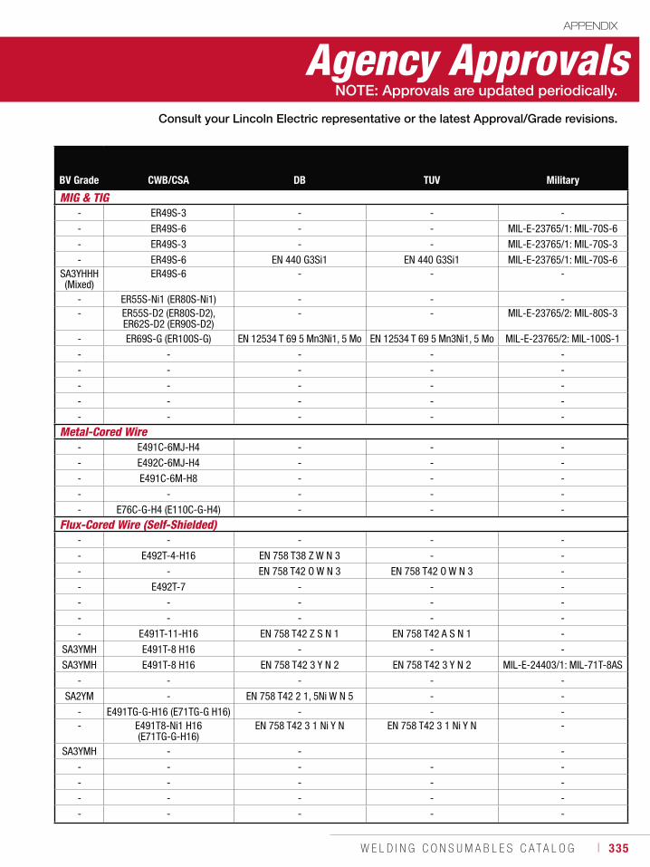
W E L D I N G C O N S U M A B L E S C A T A L O G ı 335
BV Grade CWB/CSA DB TUV Military
MIG & TIG- ER49S-3 - - -
- ER49S-6 - - MIL-E-23765/1: MIL-70S-6
- ER49S-3 - - MIL-E-23765/1: MIL-70S-3
- ER49S-6 EN 440 G3Si1 EN 440 G3Si1 MIL-E-23765/1: MIL-70S-6SA3YHHH (Mixed)
ER49S-6 - - -
- ER55S-Ni1 (ER80S-Ni1) - - -- ER55S-D2 (ER80S-D2),
ER62S-D2 (ER90S-D2)- - MIL-E-23765/2: MIL-80S-3
- ER69S-G (ER100S-G) EN 12534 T 69 5 Mn3Ni1, 5 Mo EN 12534 T 69 5 Mn3Ni1, 5 Mo MIL-E-23765/2: MIL-100S-1
- - - - -
- - - - -
- - - - -
- - - - -
- - - - -
Metal-Cored Wire- E491C-6MJ-H4 - - -
- E492C-6MJ-H4 - - -
- E491C-6M-H8 - - -
- - - - -
- E76C-G-H4 (E110C-G-H4) - - -
Flux-Cored Wire (Self-Shielded)- - - - -
- E492T-4-H16 EN 758 T38 Z W N 3 - -
- - EN 758 T42 O W N 3 EN 758 T42 O W N 3 -
- E492T-7 - - -
- - - - -
- - - - -
- E491T-11-H16 EN 758 T42 Z S N 1 EN 758 T42 A S N 1 -
SA3YMH E491T-8 H16 - - -
SA3YMH E491T-8 H16 EN 758 T42 3 Y N 2 EN 758 T42 3 Y N 2 MIL-E-24403/1: MIL-71T-8AS
- - - - -
SA2YM - EN 758 T42 2 1, 5Ni W N 5 - -
- E491TG-G-H16 (E71TG-G H16) - - -- E491T8-Ni1 H16
(E71TG-G-H16)EN 758 T42 3 1 Ni Y N EN 758 T42 3 1 Ni Y N -
SA3YMH - - -
- - - - -
- - - - -
- - - - -
- - - - -
Agency ApprovalsAPPENDIX
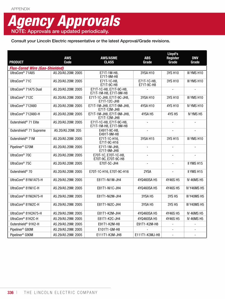
336 ı T H E L I N C O L N E L E C T R I C C O M P A N Y
PRODUCTAWS Code
AWS/ASME CLASS
ABS Grade
Lloyd's Register
GradeDNV
Grade
Flux-Cored Wire (Gas-Shielded)UltraCore® 71A85 A5.20/A5.20M: 2005 E71T-1M-H8,
E71T-9M-H83YSA H10 3YS H10 III YMS H10
UltraCore® 71C A5.20/A5.20M: 2005 E71T-1C-H8, E71T-9C-H8
E71T-1C-H8, E71T-9C-H8
3YS H10 III YMS H10
UltraCore® 71A75 Dual A5.20/A5.20M: 2005 E71T-1C-H8, E71T-9C-H8, E71T-1M-H8, E71T-9M-H8
- - -
UltraCore® 712C A5.20/A5.20M: 2005 E71T-1C-JH8, E71T-9C-JH8, E71T-12C-JH8
3YSA H10 3YS H10 III YMS H10
UltraCore® 712A80 A5.20/A5.20M: 2005 E71T-1M-JH8, E71T-9M-JH8, E71T-12M-JH8
4YSA H10 4YS H10 IV YMS H10
UltraCore® 712A80-H A5.20/A5.20M: 2005 E71T-1M-JH8, E71T-9M-JH8, E71T-12M-JH8
4YSA H5 4YS H5 IV YMS H5
Outershield® 71 Elite A5.20/A5.20M: 2005 E71T-1C-H8, E71T-9C-H8, E71T-1M-H8, E71T-9M-H8
- - -
Outershield® 71 Supreme A5.20/A5.20M: 205 E491T-9C-H8, E491T-9M-H8
- - -
Outershield® 71M A5.20/A5.20M: 2005 E71T-1C-H16, E71T-9C-H16
3YSA H15 3YS H15 III YMS H10
Pipeliner® G70M A5.20/A5.20M: 2005 E71T-1M-JH8,E71T-9M-JH8
- - -
UltraCore® 70C A5.20/A5.20M: 2005 E70T-1C, E70T-1C-H8, E70T-9C, E70T-9C-H8
- - -
UltraCore® 75C A5.20/A5.20M: 2005 E70T-5C-JH4 - - II YMS H15
Outershield® 70 A5.20/A5.20M: 2005 E70T-1C-H16, E70T-9C-H16 2YSA - II YMS H15
UltraCore® 81Ni1A75-H A5.29/A5.29M: 2005 E81T1-Ni1M-JH4 4YQ460SA H5 4Y46S H5 IV 46MS H5
UltraCore® 81Ni1C-H A5.29/A5.29M: 2005 E81T1-Ni1C-JH4 4YQ460SA H5 4Y46S H5 IV Y46MS H5
UltraCore® 81Ni2A75-H A5.29/A5.29M: 2005 E81T1-Ni2M-JH4 3YSA H5 3YS H5 III Y40MS H5
UltraCore® 81Ni2C-H A5.29/A5.29M: 2005 E81T1-Ni2C-JH4 3YSA H5 3YS H5 III Y40MS H5
UltraCore® 81K2A75-H A5.29/A5.29M: 2005 E81T1-K2M-JH4 4YQ460SA H5 4Y46S H5 IV 46MS H5
UltraCore® 81K2C-H A5.29/A5.29M: 2005 E81T1-K2C-JH4 4YQ460SA H5 4Y46S H5 IV 46MS H5
Outershield® 91K2-H A5.29/A5.29M: 2005 E91T1-K2M-H8 E91T1-K2M-H8 - -
Pipeliner® G80M A5.29/A5.29M: 2005 E101T1-GM-H8 - - -
Pipeliner® G90M A5.29/A5.29M: 2005 E111T1-K3M-JH8 E111T1-K3MJ-H8 - -
Agency ApprovalsAPPENDIX
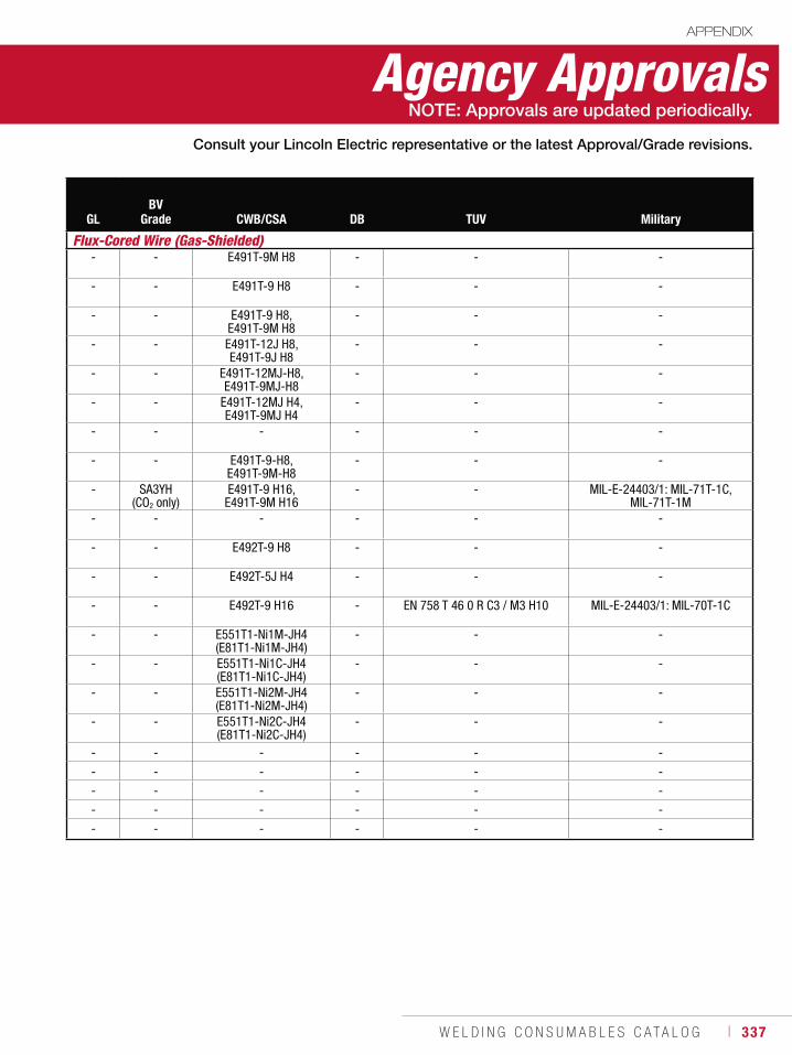
W E L D I N G C O N S U M A B L E S C A T A L O G ı 337
GLBV
Grade CWB/CSA DB TUV Military
Flux-Cored Wire (Gas-Shielded)- - E491T-9M H8 - - -
- - E491T-9 H8 - - -
- - E491T-9 H8, E491T-9M H8
- - -
- - E491T-12J H8, E491T-9J H8
- - -
- - E491T-12MJ-H8, E491T-9MJ-H8
- - -
- - E491T-12MJ H4, E491T-9MJ H4
- - -
- - - - - -
- - E491T-9-H8, E491T-9M-H8
- - -
- SA3YH (CO2 only)
E491T-9 H16, E491T-9M H16
- - MIL-E-24403/1: MIL-71T-1C, MIL-71T-1M
- - - - - -
- - E492T-9 H8 - - -
- - E492T-5J H4 - - -
- - E492T-9 H16 - EN 758 T 46 0 R C3 / M3 H10 MIL-E-24403/1: MIL-70T-1C
- - E551T1-Ni1M-JH4 (E81T1-Ni1M-JH4)
- - -
- - E551T1-Ni1C-JH4 (E81T1-Ni1C-JH4)
- - -
- - E551T1-Ni2M-JH4 (E81T1-Ni2M-JH4)
- - -
- - E551T1-Ni2C-JH4 (E81T1-Ni2C-JH4)
- - -
- - - - - -
- - - - - -
- - - - - -
- - - - - -
- - - - - -
Agency ApprovalsAPPENDIX
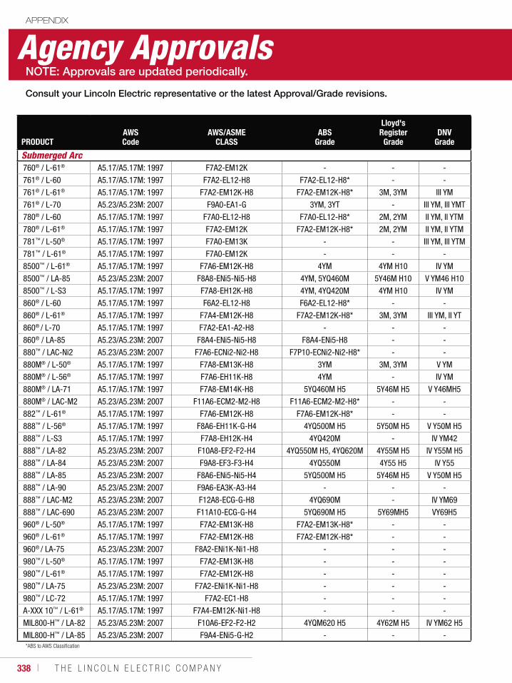
338 ı T H E L I N C O L N E L E C T R I C C O M P A N Y
Agency ApprovalsAPPENDIX
*ABS to AWS Classification
PRODUCTAWS Code
AWS/ASME CLASS
ABS Grade
Lloyd's Register
GradeDNV
Grade
Submerged Arc760® / L-61® A5.17/A5.17M: 1997 F7A2-EM12K - - -
761® / L-60 A5.17/A5.17M: 1997 F7A2-EL12-H8 F7A2-EL12-H8* - -
761® / L-61® A5.17/A5.17M: 1997 F7A2-EM12K-H8 F7A2-EM12K-H8* 3M, 3YM III YM
761® / L-70 A5.23/A5.23M: 2007 F9A0-EA1-G 3YM, 3YT - III YM, III YMT
780® / L-60 A5.17/A5.17M: 1997 F7A0-EL12-H8 F7A0-EL12-H8* 2M, 2YM II YM, II YTM
780® / L-61® A5.17/A5.17M: 1997 F7A2-EM12K F7A2-EM12K-H8* 2M, 2YM II YM, II YTM
781™ / L-50® A5.17/A5.17M: 1997 F7A0-EM13K - - III YM, III YTM
781™ / L-61® A5.17/A5.17M: 1997 F7A0-EM12K - - -
8500™ / L-61® A5.17/A5.17M: 1997 F7A6-EM12K-H8 4YM 4YM H10 IV YM
8500™ / LA-85 A5.23/A5.23M: 2007 F8A8-ENi5-Ni5-H8 4YM, 5YQ460M 5Y46M H10 V YM46 H10
8500™ / L-S3 A5.17/A5.17M: 1997 F7A8-EH12K-H8 4YM, 4YQ420M 4YM H10 IV YM
860® / L-60 A5.17/A5.17M: 1997 F6A2-EL12-H8 F6A2-EL12-H8* - -
860® / L-61® A5.17/A5.17M: 1997 F7A4-EM12K-H8 F7A2-EM12K-H8* 3M, 3YM III YM, II YT
860® / L-70 A5.17/A5.17M: 1997 F7A2-EA1-A2-H8 - - -
860® / LA-85 A5.23/A5.23M: 2007 F8A4-ENi5-Ni5-H8 F8A4-ENi5-H8 - -
880™ / LAC-Ni2 A5.23/A5.23M: 2007 F7A6-ECNi2-Ni2-H8 F7P10-ECNi2-Ni2-H8* - -
880M® / L-50® A5.17/A5.17M: 1997 F7A8-EM13K-H8 3YM 3M, 3YM V YM
880M® / L-56® A5.17/A5.17M: 1997 F7A6-EH11K-H8 4YM - IV YM
880M® / LA-71 A5.17/A5.17M: 1997 F7A8-EM14K-H8 5YQ460M H5 5Y46M H5 V Y46MH5
880M® / LAC-M2 A5.23/A5.23M: 2007 F11A6-ECM2-M2-H8 F11A6-ECM2-M2-H8* - -
882™ / L-61® A5.17/A5.17M: 1997 F7A6-EM12K-H8 F7A6-EM12K-H8* - -
888™ / L-56® A5.17/A5.17M: 1997 F8A6-EH11K-G-H4 4YQ500M H5 5Y50M H5 V Y50M H5
888™ / L-S3 A5.17/A5.17M: 1997 F7A8-EH12K-H4 4YQ420M - IV YM42
888™ / LA-82 A5.23/A5.23M: 2007 F10A8-EF2-F2-H4 4YQ550M H5, 4YQ620M 4Y55M H5 IV Y55M H5
888™ / LA-84 A5.23/A5.23M: 2007 F9A8-EF3-F3-H4 4YQ550M 4Y55 H5 IV Y55
888™ / LA-85 A5.23/A5.23M: 2007 F8A6-ENi5-Ni5-H4 5YQ500M H5 5Y46M H5 V Y50M H5
888™ / LA-90 A5.23/A5.23M: 2007 F9A6-EA3K-A3-H4 - - -
888™ / LAC-M2 A5.23/A5.23M: 2007 F12A8-ECG-G-H8 4YQ690M - IV YM69
888™ / LAC-690 A5.23/A5.23M: 2007 F11A10-ECG-G-H4 5YQ690M H5 5Y69MH5 VY69H5
960® / L-50® A5.17/A5.17M: 1997 F7A2-EM13K-H8 F7A2-EM13K-H8* - -
960® / L-61® A5.17/A5.17M: 1997 F7A2-EM12K-H8 F7A2-EM12K-H8* - -
960® / LA-75 A5.23/A5.23M: 2007 F8A2-ENi1K-Ni1-H8 - - -
980™ / L-50® A5.17/A5.17M: 1997 F7A2-EM13K-H8 - - -
980™ / L-61® A5.17/A5.17M: 1997 F7A2-EM12K-H8 - - -
980™ / LA-75 A5.23/A5.23M: 2007 F7A2-ENi1K-Ni1-H8 - - -
980™ / LC-72 A5.17/A5.17M: 1997 F7A2-EC1-H8 - - -
A-XXX 10™ / L-61® A5.17/A5.17M: 1997 F7A4-EM12K-Ni1-H8 - - -
MIL800-H™ / LA-82 A5.23/A5.23M: 2007 F10A6-EF2-F2-H2 4YQM620 H5 4Y62M H5 IV YM62 H5
MIL800-H™ / LA-85 A5.23/A5.23M: 2007 F9A4-ENi5-G-H2 - - -
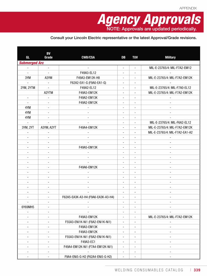
W E L D I N G C O N S U M A B L E S C A T A L O G ı 339
Agency ApprovalsAPPENDIX
GLBV
Grade CWB/CSA DB TUV Military
Submerged Arc- - - - - MIL-E-23765/4: MIL-F7A2-EM12
- - F49A3-EL12 - - -
3YM A3YM F49A3-EM12K-H8 - - MIL-E-23765/4: MIL-F7A2-EM12K
- - F62A2-EA1-G (F9A0-EA1-G) - - -
2YM, 2YTM - F49A2-EL12 - - MIL-E-23765/4: MIL-F7A0-EL12
A2YTM F49A3-EM12K - - MIL-E-23765/4: MIL-F7A2-EM12K
- - F49A2-EM13K - - -
- - F49A2-EM12K - - -
4YM - - - - -
4YM - - - - -
4YM - - - - -
- - - - - MIL-E-23765/4: MIL-F6A2-EL12
3YM, 2YT A3YM, A2YT F49A4-EM12K - - MIL-E-23765/4: MIL-F7A2-EM12K
- - - - - MIL-E-23765/4: MIL-F7A2-EA1-A2
- - - - - -
- - - - - -
- - F49A5-EM13K - - -
- - - - - -
- - - - - -
- - - - - -
- - F49A6-EM12K - - -
- - - - - -
- - - - - -
- - - - - -
- - - - - -
- - - - - -
- - F62A5-EA3K-A3-H4 (F9A6-EA3K-A3-H4) - - -
- - - - - -
6Y69MH5 - - - - -
- - - - - -
- - F49A3-EM12K - - MIL-E-23765/4: MIL-F7A2-EM12K
- - F55A3-ENi1K-Ni1 (F8A2-ENi1K-Ni1) - - -
- - F49A3-EM13K - - -
- - F49A3-EM12K - - -
- - F55A3-ENi1K-Ni1 (F8A2-ENi1K-Ni1) - - -
- - F49A3-EC1 - - -
- - F49A4-EM12K-Ni1 (F7A4-EM12K-Ni1) - - -
- - - - - -
- - F9A4-ENi5-G-H2 (F62A4-ENi5-G-H2) - - -
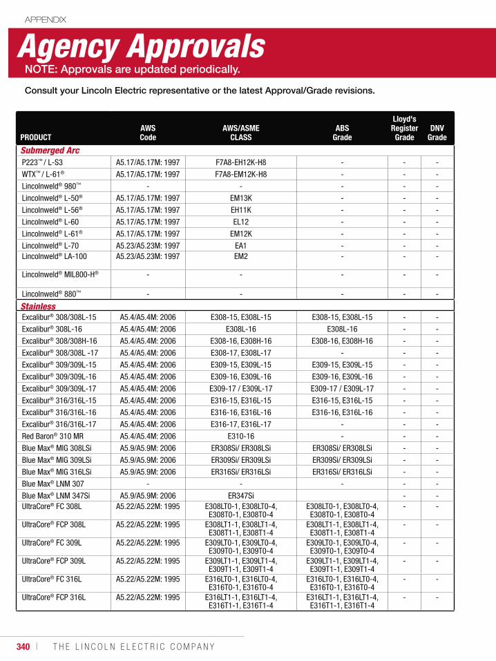
340 ı T H E L I N C O L N E L E C T R I C C O M P A N Y
Agency ApprovalsAPPENDIX
PRODUCTAWS Code
AWS/ASME CLASS
ABS Grade
Lloyd's Register
GradeDNV
Grade
Submerged ArcP223™ / L-S3 A5.17/A5.17M: 1997 F7A8-EH12K-H8 - - -
WTX™ / L-61® A5.17/A5.17M: 1997 F7A8-EM12K-H8 - - -
Lincolnweld® 980™ - - - - -
Lincolnweld® L-50® A5.17/A5.17M: 1997 EM13K - - -
Lincolnweld® L-56® A5.17/A5.17M: 1997 EH11K - - -
Lincolnweld® L-60 A5.17/A5.17M: 1997 EL12 - - -
Lincolnweld® L-61® A5.17/A5.17M: 1997 EM12K - - -
Lincolnweld® L-70 A5.23/A5.23M: 1997 EA1 - - -Lincolnweld® LA-100 A5.23/A5.23M: 1997 EM2 - - -
Lincolnweld® MIL800-H® - - - - -
Lincolnweld® 880™ - - - - -
StainlessExcalibur® 308/308L-15 A5.4/A5.4M: 2006 E308-15, E308L-15 E308-15, E308L-15 - -
Excalibur® 308L-16 A5.4/A5.4M: 2006 E308L-16 E308L-16 - -
Excalibur® 308/308H-16 A5.4/A5.4M: 2006 E308-16, E308H-16 E308-16, E308H-16 - -
Excalibur® 308/308L -17 A5.4/A5.4M: 2006 E308-17, E308L-17 - - -
Excalibur® 309/309L-15 A5.4/A5.4M: 2006 E309-15, E309L-15 E309-15, E309L-15 - -
Excalibur® 309/309L-16 A5.4/A5.4M: 2006 E309-16, E309L-16 E309-16, E309L-16 - -
Excalibur® 309/309L-17 A5.4/A5.4M: 2006 E309-17 / E309L-17 E309-17 / E309L-17 - -
Excalibur® 316/316L-15 A5.4/A5.4M: 2006 E316-15, E316L-15 E316-15, E316L-15 - -
Excalibur® 316/316L-16 A5.4/A5.4M: 2006 E316-16, E316L-16 E316-16, E316L-16 - -
Excalibur® 316/316L-17 A5.4/A5.4M: 2006 E316-17, E316L-17 - - -
Red Baron® 310 MR A5.4/A5.4M: 2006 E310-16 - - -
Blue Max® MIG 308LSi A5.9/A5.9M: 2006 ER308Si/ ER308LSi ER308Si/ ER308LSi - -
Blue Max® MIG 309LSi A5.9/A5.9M: 2006 ER309Si/ ER309LSi ER309Si/ ER309LSi - -
Blue Max® MIG 316LSi A5.9/A5.9M: 2006 ER316Si/ ER316LSi ER316Si/ ER316LSi - -
Blue Max® LNM 307 - - - - -
Blue Max® LNM 347Si A5.9/A5.9M: 2006 ER347Si - -UltraCore® FC 308L A5.22/A5.22M: 1995 E308LT0-1, E308LT0-4,
E308T0-1, E308T0-4E308LT0-1, E308LT0-4, E308T0-1, E308T0-4
- -
UltraCore® FCP 308L A5.22/A5.22M: 1995 E308LT1-1, E308LT1-4, E308T1-1, E308T1-4
E308LT1-1, E308LT1-4, E308T1-1, E308T1-4
- -
UltraCore® FC 309L A5.22/A5.22M: 1995 E309LT0-1, E309LT0-4, E309T0-1, E309T0-4
E309LT0-1, E309LT0-4, E309T0-1, E309T0-4
- -
UltraCore® FCP 309L A5.22/A5.22M: 1995 E309LT1-1, E309LT1-4, E309T1-1, E309T1-4
E309LT1-1, E309LT1-4, E309T1-1, E309T1-4
- -
UltraCore® FC 316L A5.22/A5.22M: 1995 E316LT0-1, E316LT0-4, E316T0-1, E316T0-4
E316LT0-1, E316LT0-4, E316T0-1, E316T0-4
- -
UltraCore® FCP 316L A5.22/A5.22M: 1995 E316LT1-1, E316LT1-4, E316T1-1, E316T1-4
E316LT1-1, E316LT1-4, E316T1-1, E316T1-4
- -
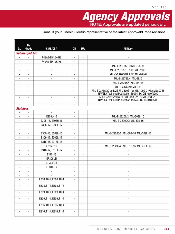
W E L D I N G C O N S U M A B L E S C A T A L O G ı 341
Agency ApprovalsAPPENDIX
GLBV
Grade CWB/CSA DB TUV Military
Submerged Arc- - F49A6-EH12K-H8 - - -
- - F49A6-EM12K-H8 - - -
- - - - - MIL-E-23765/1E: MIL-70S-3F
- - - - - MIL-E-23765/1D &1E: MIL-70S-3
- - - - - MIL-E-23765/1D & 1E: MIL-70S-6
- - - - - MIL-E-23765/4: MIL-EL12
- - - - - MIL-E-23765/4: MIL-EM12K
- - - - - MIL-E-23765/4: MIL-EA1- - - - - MIL-E-23765/2D and /2E: MIL-100S-1 or MIL-100S-2 (with MIL800-H)
NAVSEA Technical Publication T9074-BC-GIB-010/0200- - - - - MIL-E-23765/2D & 2E: MIL-100S-2F or MIL-100S-1F
NAVSEA Technical Publication T9074-BC-GIB-010/0200- - - - - -
Stainless- - - - - -
- - E308L-16 - - MIL-E-22200/2: MIL-308L-16
- - E308-16, E308H-16 - - MIL-E-22200/2: MIL-308-16
- - E308-17, E308L-17 - - -
- - - - - -
- - E309-16, E309L-16 - - MIL-E-22200/2: MIL-309-16, MIL-309L-16
- - E309-17, E309L-17 - - -
- - E316-15, E316L-15 - - -
- - E316L-16 - - MIL-E-22200/2: MIL-316-16, MIL-316L-16
- - E316-17, E316L-17 - - -
- - E310-16 - - -
- - ER308LSi - - -
- - ER309LSi - - -
- - ER316LSi - - -
- - - - - -
- - - - - -- - E308LT0-1, E308LT0-4 - - -
- - E308LT1-1, E308LT1-4 - - -
- - E309LT0-1, E309LT0-4 - - -
- - E309LT1-1, E309LT1-4 - - -
- - E316LT0-1, E316LT0-4 - - -
- - E316LT1-1, E316LT1-4 - - -
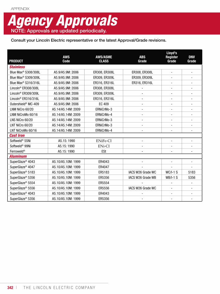
342 ı T H E L I N C O L N E L E C T R I C C O M P A N Y
Agency ApprovalsAPPENDIX
PRODUCTAWS Code
AWS/ASME CLASS
ABS Grade
Lloyd's Register
GradeDNV
Grade
Stainless Blue Max® S308/308L A5.9/A5.9M: 2006 ER308, ER308L ER308, ER308L - -
Blue Max® S309/309L A5.9/A5.9M: 2006 ER309, ER309L ER309, ER309L - -
Blue Max® S316/316L A5.9/A5.9M: 2006 ER316, ER316L ER316, ER316L - -
Lincoln® ER308/308L A5.9/A5.9M: 2006 ER308, ER308L - - -
Lincoln® ER309/309L A5.9/A5.9M: 2006 ER309, ER309L - - -
Lincoln® ER316/316L A5.9/A5.9M: 2006 ER316, ER316L - - -
Outershield® MC-409 A5.9/A5.9M: 2006 EC 409 - - -
LNM NiCro 60/20 A5.14/A5.14M: 2009 ERNiCrMo-3 - - -
LNM NiCroMo 60/16 A5.14/A5.14M: 2009 ERNiCrMo-4 - - -
LNS NiCro 60/20 A5.14/A5.14M: 2009 ERNiCrMo-3 - - -
LNT NiCro 60/20 A5.14/A5.14M: 2009 ERNiCrMo-3 - - -
LNT NiCroMo 60/16 A5.14/A5.14M: 2009 ERNiCrMo-4 - - -Cast IronSoftweld® 55Ni A5.15: 1990 - - -
Softweld® 99Ni A5.15: 1990 - - -
Ferroweld® A5.15: 1990 ESt - - -AluminumSuperGlaze® 4043 A5.10/A5.10M: 1999 ER4043 - - -
SuperGlaze® 4047 A5.10/A5.10M: 1999 ER4047 - - -
SuperGlaze® 5183 A5.10/A5.10M: 1999 ER5183 IACS W26 Grade WC WC/I-1 S 5183
SuperGlaze® 5356 A5.10/A5.10M: 1999 ER5356 IACS W26 Grade WB WB/I-1 S 5356
SuperGlaze® 5554 A5.10/A5.10M: 1999 ER5554 - - -
SuperGlaze® 5556 A5.10/A5.10M: 1999 ER5556 IACS W26 Grade WC - -
SuperGlaze® 4043 A5.10/A5.10M: 1999 ER4043 - - -
SuperGlaze® 5356 A5.10/A5.10M: 1999 ER5356 - - -
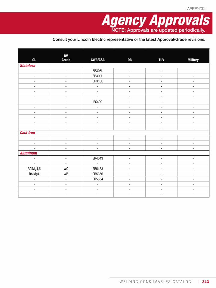
W E L D I N G C O N S U M A B L E S C A T A L O G ı 343
Agency ApprovalsAPPENDIX
GLBV
Grade CWB/CSA DB TUV Military
Stainless- - ER308L - - -
- - ER309L - - -
- - ER316L - - -
- - - - - -
- - - - - -
- - - - - -
- - EC409 - - -
- - - - - -
- - - - - -
- - - - - -
- - - - - -
- - - - - -Cast Iron
- - - - - -
- - - - - -
- - - - - -Aluminum
- - ER4043 - - -
- - - - - -
RAIMg4,5 WC ER5183 - - -
RAIMg4 WB ER5356 - - -
- - ER5554 - - -
- - - - - -
- - - - - -
- - - - - -
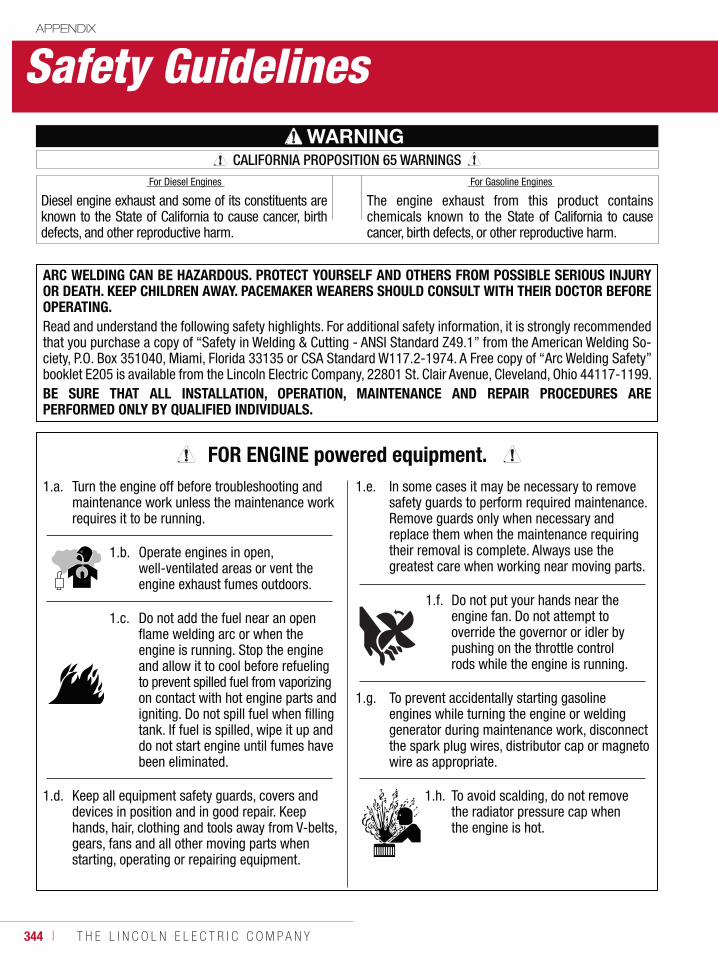
344 ı T H E L I N C O L N E L E C T R I C C O M P A N Y
Safety GuidelinesAPPENDIX
WARNINGCALIFORNIA PROPOSITION 65 WARNINGS
Diesel engine exhaust and some of its constituents are known to the State of California to cause cancer, birth defects, and other reproductive harm.
The engine exhaust from this product contains chemicals known to the State of California to cause cancer, birth defects, or other reproductive harm.
ARC WELDING CAN BE HAZARDOUS. PROTECT YOURSELF AND OTHERS FROM POSSIBLE SERIOUS INJURY OR DEATH. KEEP CHILDREN AWAY. PACEMAKER WEARERS SHOULD CONSULT WITH THEIR DOCTOR BEFORE OPERATING.Read and understand the following safety highlights. For additional safety information, it is strongly recommended that you purchase a copy of “Safety in Welding & Cutting - ANSI Standard Z49.1” from the American Welding So-ciety, P.O. Box 351040, Miami, Florida 33135 or CSA Standard W117.2-1974. A Free copy of “Arc Welding Safety” booklet E205 is available from the Lincoln Electric Company, 22801 St. Clair Avenue, Cleveland, Ohio 44117-1199.BE SURE THAT ALL INSTALLATION, OPERATION, MAINTENANCE AND REPAIR PROCEDURES ARE PERFORMED ONLY BY QUALIFIED INDIVIDUALS.
For Diesel Engines For Gasoline Engines
1.a. Turn the engine off before troubleshooting and maintenance work unless the maintenance work requires it to be running.
1.b. Operate engines in open, well-ventilated areas or vent the engine exhaust fumes outdoors.
1.c. Do not add the fuel near an open flame welding arc or when the engine is running. Stop the engine and allow it to cool before refueling to prevent spilled fuel from vaporizing on contact with hot engine parts and igniting. Do not spill fuel when filling tank. If fuel is spilled, wipe it up and do not start engine until fumes have been eliminated.
1.d. Keep all equipment safety guards, covers and devices in position and in good repair. Keep hands, hair, clothing and tools away from V-belts, gears, fans and all other moving parts when starting, operating or repairing equipment.
1.e. In some cases it may be necessary to remove safety guards to perform required maintenance. Remove guards only when necessary and replace them when the maintenance requiring their removal is complete. Always use the greatest care when working near moving parts.
1.f. Do not put your hands near the engine fan. Do not attempt to override the governor or idler by pushing on the throttle control rods while the engine is running.
1.g. To prevent accidentally starting gasoline engines while turning the engine or welding generator during maintenance work, disconnect the spark plug wires, distributor cap or magneto wire as appropriate.
1.h. To avoid scalding, do not remove the radiator pressure cap when the engine is hot.
FOR ENGINE powered equipment.
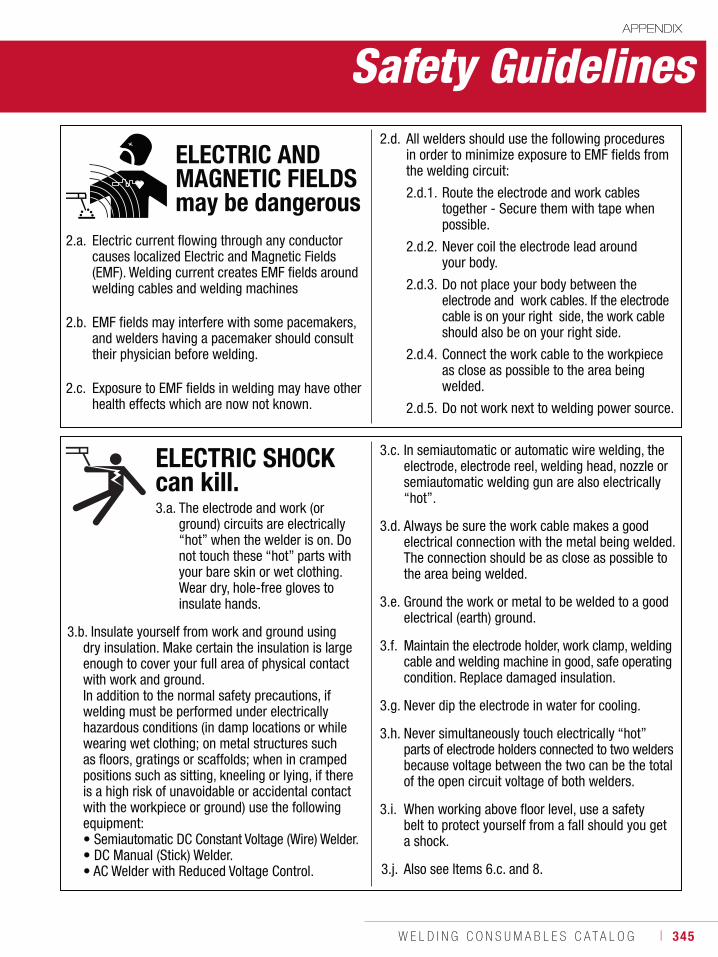
W E L D I N G C O N S U M A B L E S C A T A L O G ı 345
APPENDIX
Safety Guidelines
2.a. Electric current flowing through any conductor causes localized Electric and Magnetic Fields (EMF). Welding current creates EMF fields around welding cables and welding machines
2.b. EMF fields may interfere with some pacemakers, and welders having a pacemaker should consult their physician before welding.
2.c. Exposure to EMF fields in welding may have other health effects which are now not known.
2.d. All welders should use the following procedures in order to minimize exposure to EMF fields from the welding circuit:
2.d.1. Route the electrode and work cables together - Secure them with tape when possible.
2.d.2. Never coil the electrode lead around your body.
2.d.3. Do not place your body between the electrode and work cables. If the electrode cable is on your right side, the work cable should also be on your right side.
2.d.4. Connect the work cable to the workpiece as close as possible to the area being welded.
2.d.5. Do not work next to welding power source.
ELECTRIC AND MAGNETIC FIELDS may be dangerous
3.a. The electrode and work (or ground) circuits are electrically “hot” when the welder is on. Do not touch these “hot” parts with your bare skin or wet clothing. Wear dry, hole-free gloves to insulate hands.
3.b. Insulate yourself from work and ground using dry insulation. Make certain the insulation is large enough to cover your full area of physical contact with work and ground. In addition to the normal safety precautions, if welding must be performed under electrically hazardous conditions (in damp locations or while wearing wet clothing; on metal structures such as floors, gratings or scaffolds; when in cramped positions such as sitting, kneeling or lying, if there is a high risk of unavoidable or accidental contact with the workpiece or ground) use the following equipment: • Semiautomatic DC Constant Voltage (Wire) Welder.• DC Manual (Stick) Welder. • AC Welder with Reduced Voltage Control.
3.c. In semiautomatic or automatic wire welding, the electrode, electrode reel, welding head, nozzle or semiautomatic welding gun are also electrically “hot”.
3.d. Always be sure the work cable makes a good electrical connection with the metal being welded. The connection should be as close as possible to the area being welded.
3.e. Ground the work or metal to be welded to a good electrical (earth) ground.
3.f. Maintain the electrode holder, work clamp, welding cable and welding machine in good, safe operating condition. Replace damaged insulation.
3.g. Never dip the electrode in water for cooling.
3.h. Never simultaneously touch electrically “hot” parts of electrode holders connected to two welders because voltage between the two can be the total of the open circuit voltage of both welders.
3.i. When working above floor level, use a safety belt to protect yourself from a fall should you get a shock.
3.j. Also see Items 6.c. and 8.
ELECTRIC SHOCK can kill.
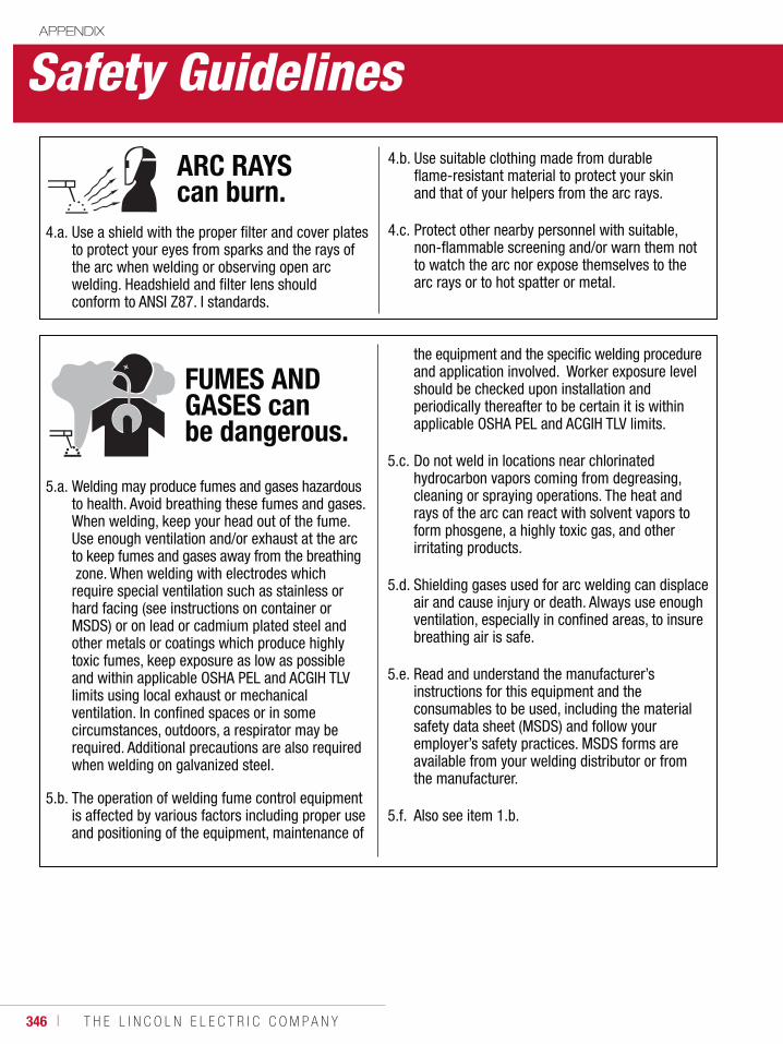
346 ı T H E L I N C O L N E L E C T R I C C O M P A N Y
5.a. Welding may produce fumes and gases hazardous to health. Avoid breathing these fumes and gases. When welding, keep your head out of the fume. Use enough ventilation and/or exhaust at the arc to keep fumes and gases away from the breathing zone. When welding with electrodes which require special ventilation such as stainless or hard facing (see instructions on container or MSDS) or on lead or cadmium plated steel and other metals or coatings which produce highly toxic fumes, keep exposure as low as possible and within applicable OSHA PEL and ACGIH TLV limits using local exhaust or mechanical ventilation. In confined spaces or in some circumstances, outdoors, a respirator may be required. Additional precautions are also required when welding on galvanized steel.
5.b. The operation of welding fume control equipment is affected by various factors including proper use and positioning of the equipment, maintenance of
the equipment and the specific welding procedure and application involved. Worker exposure level should be checked upon installation and periodically thereafter to be certain it is within applicable OSHA PEL and ACGIH TLV limits.
5.c. Do not weld in locations near chlorinated hydrocarbon vapors coming from degreasing, cleaning or spraying operations. The heat and rays of the arc can react with solvent vapors to form phosgene, a highly toxic gas, and other irritating products.
5.d. Shielding gases used for arc welding can displace air and cause injury or death. Always use enough ventilation, especially in confined areas, to insure breathing air is safe.
5.e. Read and understand the manufacturer’s instructions for this equipment and the consumables to be used, including the material safety data sheet (MSDS) and follow your employer’s safety practices. MSDS forms are available from your welding distributor or from the manufacturer.
5.f. Also see item 1.b.
APPENDIX
Safety Guidelines
4.a. Use a shield with the proper filter and cover plates to protect your eyes from sparks and the rays of the arc when welding or observing open arc welding. Headshield and filter lens should conform to ANSI Z87. I standards.
4.b. Use suitable clothing made from durable flame-resistant material to protect your skin and that of your helpers from the arc rays.
4.c. Protect other nearby personnel with suitable, non-flammable screening and/or warn them not to watch the arc nor expose themselves to the arc rays or to hot spatter or metal.
ARC RAYS can burn.
FUMES AND GASES can be dangerous.
W E L D I N G C O N S U M A B L E S C A T A L O G ı 347
APPENDIX
Safety Guidelines
6.a. Remove fire hazards from the welding area. If this is not possible, cover them to prevent the welding sparks from starting a fire. Remember that welding sparks and hot materials from welding can easily go through small cracks and openings to adjacent areas. Avoid welding near hydraulic lines. Have a fire extinguisher readily available.
6.b. Where compressed gases are to be used at the job site, special precautions should be used to prevent hazardous situations. Refer to “Safety in Welding and Cutting” (ANSI Standard Z49.1) and the operating information for the equipment being used.
6.c. When not welding, make certain no part of the electrode circuit is touching the work or ground. Accidental contact can cause overheating and create a fire hazard.
6.d. Do not heat, cut or weld tanks, drums or containers until the proper steps have been taken to insure that such procedures will not cause flammable or toxic vapors from substances inside. They can cause an explosion even though they have been “cleaned”. For information, purchase “Recommended Safe Practices for the Preparation for Welding and Cutting of Containers
and Piping That Have Held Hazardous Substances”, AWS F4.1 from the American Welding Society (see address above).
6.e. Vent hollow castings or containers before heating, cutting or welding. They may explode.
6.f. Sparks and spatter are thrown from the welding arc. Wear oil free protective garments such as leather gloves, heavy shirt, cuffless trousers, high shoes and a cap over your hair. Wear ear plugs when welding out of position or in confined places. Always wear safety glasses with side shields when in a welding area.
6.g. Connect the work cable to the work as close to the welding area as practical. Work cables connected to the building framework or other locations away from the welding area increase the possibility of the welding current passing through lifting chains, crane cables or other alternate circuits. This can create fire hazards or overheat lifting chains or cables until they fail.
6.h. Also see item 1.c.
6.I. Read and follow NFPA 51B “Standard for Fire Prevention During Welding, Cutting and Other Hot Work”, available from NFPA, 1 Batterymarch Park, PO box 9101, Quincy, Ma 022690-9101.
6.j. Do not use a welding power source for pipe thawing.
WELDING and CUTTING SPARKS can cause fire or explosion.
348 ı T H E L I N C O L N E L E C T R I C C O M P A N Y
7.a. Use only compressed gas cylinders containing the correct shielding gas for the process used and properly operating regulators designed for the gas and pressure used. All hoses, fittings, etc. should be suitable for the application and maintained in good condition.
7.b. Always keep cylinders in an upright position securely chained to an undercarriage or fixed support.
7.c. Cylinders should be located: • Away from areas where they may be struck or subjected to physical damage. • A safe distance from arc welding or cutting operations and any other source of heat, sparks, or flame.
7.d. Never allow the electrode, electrode holder or any other electrically “hot” parts to touch a cylinder.
7.e. Keep your head and face away from the cylinder valve outlet when opening the cylinder valve.
7.f. Valve protection caps should always be in place and hand tight except when the cylinder is in use or connected for use.
7.g. Read and follow the instructions on compressed gas cylinders, associated equipment, and CGA publication P-l, “Precautions for Safe Handling of Compressed Gases in Cylinders,” available from the Compressed Gas Association 1235 Jefferson Davis Highway, Arlington, VA 22202.
CYLINDER may explode if damaged.
8.a. Turn off input power using the disconnect switch at the fuse box before working on the equipment.
8.b. Install equipment in accordance with the U.S. National Electrical Code, all local codes and the manufacturer’s recommendations.
8.c. Ground the equipment in accordance with the U.S. National Electrical Code and the manufacturer’s recommendations.
FOR ELECTRICALLY powered equipment.
Refer to http://www.lincolnelectric.com/safety for additional safety information.
APPENDIX
Safety Guidelines
W E L D I N G C O N S U M A B L E S C A T A L O G ı 349
Fumes and GasesBecause of the variables involved in fume and gas generation from arc welding, cutting and allied processes (such as the welding process and electrode, the base metal, coatings on the base metal, and other possible contaminants in the air), we’ll have to treat the subject in a rather general way, lumping all but the more hazardous situations together. The precautions we describe will hold true for all arc welding processes.
The fume plume contains solid particles from the consumables, base metal, and base metal coating. For common mild steel arc welding, depending on the amount and length of exposure to these fumes, most immediate or short term effects are temporary, and include symptoms of burning eyes and skin, dizziness, nausea, and fever. For example, zinc fumes can cause metal fume fever, a temporary illness that is similar to the flu.
Long-term exposure to welding fumes can lead to siderosis (iron deposits in the lungs) and may affect pulmonary function. Bronchitis and some lung fibrosis have been reported.
Some consumables contain certain compounds in amounts which may require special ventilation and/or exhaust. These Special Ventilation products can be identified by reading the labels on the package. If Special Ventilation products are used indoors, use local exhaust. If Special Ventilation products are used outdoors, a respirator may be required. Various compounds, some of which may be in welding fume, and reported health effects, in summary, are:
Barium: Soluble barium compounds may cause severe stomach pain, slow pulse rate, irregular heart beat, ringing of the ears, convulsions and muscle spasms. In extreme cases can cause death.
Cadmium also requires extra precautions. This toxic
metal can be found on some steel and steel fasteners as a plating, or in silver solder. Cadmium fumes can be fatal even under brief overexposures, with symptoms much like those of metal fume fever. These two conditions should not be confused. Overexposure to cadmium can be enough to cause fatalities, with symptoms appearing quickly, and, in some circumstances, death a few days later.
Chromium: Chromium is on the IARC (International Agency for Research on Cancer) and NTP (National Toxicology Program) lists chromium as posing a carcinogenic risk to humans. Fumes from the use of stainless steel, hardfacing and other types of consumables contain chromium and/or nickel. Some forms of these metals are known or suspected to cause lung cancer in processes other than welding and asthma has been reported. Therefore, it is recommended that precautions be taken to keep exposures as low as possible. OSHA recently adopted a lower PEL (Permissible Exposure Limit) for chromium (see Supplement 3). The use of local exhaust and/or an approved respirator may be required to avoid overexposure.
Coatings on the metal to be welded, such as paint, may also contain toxic substances, such as lead, chromium and zinc. In general, it is always best to remove coatings from the base metal before welding or cutting.
Cobalt: Exposure to cobalt can cause respiratory disease and pulmonary sensitization. Cobalt in metallic form has been reported to cause lung damage.
Copper: Prolonged exposure to copper fume may cause skin irritation or discoloration of the skin and hair.
Manganese: Manganese overexposure may affect the central nervous system, resulting in poor coordination, difficulty in speaking, and tremor of arms or legs. This condition is considered irreversible.
Nickel: Nickel and its compounds are on the IARC (International Agency for Research on Cancer) and NTP (National Toxicology Program) lists as posing a carcinogenic risk to humans.
Silica: Crystalline silica is present in respirable dust form submerged arc flux. Overexposure can cause severe lung damage (silicosis).
Zinc: Overexposure to zinc (from galvanized metals) may cause metal fume fever with symptoms similar to the common flu.
FUMES & GASES can be dangerous to your health• Keep fumes and gases from your breathing zone and general area.• Keep your head out of the fumes.• Use enough ventilation or exhaust at the arc, or both, to keep fumes and gases from your breathing zone and general area.
APPENDIX
Safety Guidelines WARNING
350 ı T H E L I N C O L N E L E C T R I C C O M P A N Y
The gases that result from an arc welding process also present potential hazard. Most of the shielding gases (argon, helium, and carbon dioxide) are non-toxic, but, as they are released, they displace oxygen in your breathing air, causing dizziness, unconsciousness, and death, the longer your brain is denied the oxygen it needs. Carbon monoxide can also be developed and may pose a hazard if excessive levels are present.
The heat and UV radiation can cause irritation to the eyes and lungs. Some degreasing compounds such as trichlorethylene and perchlorethylene can decompose from the heat and ultraviolet radiation of an arc. Because of the chemical breakdown of vapor-degreasing materials under ultraviolet radiation, arc welding should not be done in the vicinity of a vapor-degreasing operation. Carbon-arc welding, gas tungsten-arc welding and gas metal arc welding should be especially avoided in such areas, because they emit more ultraviolet radiation than other processes. Also, keep in mind that ozone and nitrogen oxides are formed when UV radiation passes through the air. These gases cause headaches, chest pains, irritation of the eyes, and an itchiness in the nose and throat.
There is one easy way to reduce the risk of exposure to hazardous fumes and gases: keep your head out of the fume plume! As obvious as this sounds, the failure to follow this advice is a common cause of fume and gas overexposure because the concentration of fume and gases is greatest in the plume. Keep fumes and gases from your breathing zone and general area using natural ventilation, mechanical ventilation, fixed or moveable exhaust hoods or local exhaust at the arc. Finally, it may be necessary to wear an approved respirator if adequate ventilation cannot be provided.
As a rule of thumb, for many mild steel electrode, if the air is visibly clear and you are comfortable, then the ventilation is generally adequate for your work. The most accurate way to determine if the worker exposure does not exceed the applicable exposure limit for compounds in the fumes and gases is to have an industrial hygienist take and analyze a sample of the air you are breathing. This is particularly important if you are welding with
stainless, hardfacing or Special Ventilation products. All Lincoln MSDS have a maximum fume guideline number. If exposure to total fume is kept below that number, exposure to all fume from the electrode (not coatings or plating on the work) will be below the TLV.
There are also steps that you can take to identify hazardous substances in your welding environment. First, read the product label and material safety data sheet for the electrode posted in the work place or in the electrode or flux container to see what fumes can be reasonably expected from use of the product and to determine if special ventilation is needed. Secondly, know what the base metal is, and determine if there is any paint, plating, or coating that could expose you to toxic fumes and/or gases. Remove it from the metal being welded, if possible. If you start to feel uncomfortable, dizzy or nauseous, there is a possibility that you are being overexposed to fumes and gases, or suffering from oxygen deficiency. Stop welding and get some fresh air immediately. Notify your supervisor and co-workers so the situation can be corrected and other workers can avoid the hazard. Be sure you are following these safe practices, the consumable labeling and MSDS and improve the ventilation in your area. Do not continue welding until the situation has been corrected.
NOTE: The MSDS for all Lincoln consumables is available on Lincoln’s website: www.lincolnelectric.com
Before we turn to the methods available to control welding fume exposure, you should understand a few basic terms:
Natural Ventilation is the movement of air through the workplace caused by natural forces. Outside, this is usually the wind. Inside, this may be the flow of air through open windows and doors.
Mechanical Ventilation is the movement of air through the workplace caused by an electrical device such as a portable fan or permanently mounted fan in the ceiling or wall.
Source Extraction (Local Exhaust) is a mechanical device used to capture welding fume at or near the arc and filter contaminants out of the air.
APPENDIX
Safety Guidelines
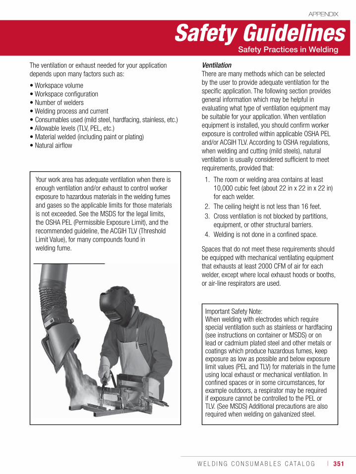
W E L D I N G C O N S U M A B L E S C A T A L O G ı 351
APPENDIX
Safety GuidelinesVentilationThere are many methods which can be selected by the user to provide adequate ventilation for the specific application. The following section provides general information which may be helpful in evaluating what type of ventilation equipment may be suitable for your application. When ventilation equipment is installed, you should confirm worker exposure is controlled within applicable OSHA PEL and/or ACGIH TLV. According to OSHA regulations, when welding and cutting (mild steels), natural ventilation is usually considered sufficient to meet requirements, provided that:
1. The room or welding area contains at least 10,000 cubic feet (about 22 in x 22 in x 22 in) for each welder.2. The ceiling height is not less than 16 feet.3. Cross ventilation is not blocked by partitions, equipment, or other structural barriers.4. Welding is not done in a confined space.
Your work area has adequate ventilation when there is enough ventilation and/or exhaust to control worker exposure to hazardous materials in the welding fumes and gases so the applicable limits for those materials is not exceeded. See the MSDS for the legal limits, the OSHA PEL (Permissible Exposure Limit), and the recommended guideline, the ACGIH TLV (Threshold Limit Value), for many compounds found in welding fume.
Important Safety Note:When welding with electrodes which require special ventilation such as stainless or hardfacing (see instructions on container or MSDS) or on lead or cadmium plated steel and other metals or coatings which produce hazardous fumes, keep exposure as low as possible and below exposure limit values (PEL and TLV) for materials in the fume using local exhaust or mechanical ventilation. In confined spaces or in some circumstances, for example outdoors, a respirator may be required if exposure cannot be controlled to the PEL or TLV. (See MSDS) Additional precautions are also required when welding on galvanized steel.
Spaces that do not meet these requirements should be equipped with mechanical ventilating equipment that exhausts at least 2000 CFM of air for each welder, except where local exhaust hoods or booths, or air-line respirators are used.
The ventilation or exhaust needed for your application depends upon many factors such as:
• Workspace volume• Workspace configuration• Number of welders• Welding process and current• Consumables used (mild steel, hardfacing, stainless, etc.)• Allowable levels (TLV, PEL, etc.)• Material welded (including paint or plating)• Natural airflow
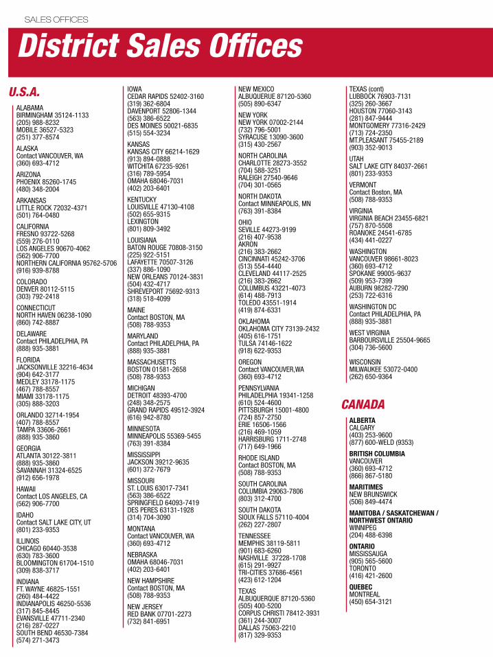
ALABAMABIRMINGHAM 35124-1133(205) 988-8232MOBILE 36527-5323(251) 377-8574
ALASKAContact VANCOUVER, WA(360) 693-4712
ARIZONAPHOENIX 85260-1745(480) 348-2004
ARKANSASLITTLE ROCK 72032-4371(501) 764-0480
CALIFORNIAFRESNO 93722-5268(559) 276-0110LOS ANGELES 90670-4062(562) 906-7700NORTHERN CALIFORNIA 95762-5706(916) 939-8788
COLORADODENVER 80112-5115(303) 792-2418
CONNECTICUTNORTH HAVEN 06238-1090(860) 742-8887
DELAWAREContact PHILADELPHIA, PA(888) 935-3881
FLORIDAJACKSONVILLE 32216-4634(904) 642-3177MEDLEY 33178-1175(467) 788-8557MIAMI 33178-1175(305) 888-3203
ORLANDO 32714-1954(407) 788-8557TAMPA 33606-2661(888) 935-3860
GEORGIAATLANTA 30122-3811(888) 935-3860SAVANNAH 31324-6525(912) 656-1978
HAWAIIContact LOS ANGELES, CA(562) 906-7700
IDAHOContact SALT LAKE CITY, UT(801) 233-9353
ILLINOISCHICAGO 60440-3538(630) 783-3600BLOOMINGTON 61704-1510(309) 838-3717
INDIANAFT. WAYNE 46825-1551(260) 484-4422INDIANAPOLIS 46250-5536(317) 845-8445EVANSVILLE 47711-2340(216) 287-0227SOUTH BEND 46530-7384(574) 271-3473
IOWACEDAR RAPIDS 52402-3160(319) 362-6804DAVENPORT 52806-1344(563) 386-6522DES MOINES 50021-6835(515) 554-3234
KANSASKANSAS CITY 66214-1629(913) 894-0888 WITCHITA 67235-9261(316) 789-5954OMAHA 68046-7031(402) 203-6401
KENTUCKYLOUISVILLE 47130-4108(502) 655-9315LEXINGTON(801) 809-3492
LOUISIANABATON ROUGE 70808-3150(225) 922-5151LAFAYETTE 70507-3126(337) 886-1090NEW ORLEANS 70124-3831(504) 432-4717SHREVEPORT 75692-9313(318) 518-4099
MAINE Contact BOSTON, MA(508) 788-9353
MARYLAND Contact PHILADELPHIA, PA(888) 935-3881
MASSACHUSETTSBOSTON 01581-2658(508) 788-9353
MICHIGANDETROIT 48393-4700(248) 348-2575GRAND RAPIDS 49512-3924(616) 942-8780
MINNESOTAMINNEAPOLIS 55369-5455(763) 391-8384
MISSISSIPPIJACKSON 39212-9635(601) 372-7679
MISSOURIST. LOUIS 63017-7341(563) 386-6522SPRINGFIELD 64093-7419DES PERES 63131-1928(314) 704-3090
MONTANAContact VANCOUVER, WA(360) 693-4712
NEBRASKAOMAHA 68046-7031(402) 203-6401
NEW HAMPSHIREContact BOSTON, MA(508) 788-9353
NEW JERSEYRED BANK 07701-2273(732) 841-6951
NEW MEXICOALBUQUERUE 87120-5360(505) 890-6347
NEW YORKNEW YORK 07002-2144(732) 796-5001SYRACUSE 13090-3600(315) 430-2567
NORTH CAROLINACHARLOTTE 28273-3552(704) 588-3251RALEIGH 27540-9646(704) 301-0565
NORTH DAKOTAContact MINNEAPOLIS, MN (763) 391-8384
OHIOSEVILLE 44273-9199(216) 407-9538AKRON(216) 383-2662CINCINNATI 45242-3706(513) 554-4440CLEVELAND 44117-2525(216) 383-2662COLUMBUS 43221-4073(614) 488-7913TOLEDO 43551-1914(419) 874-6331
OKLAHOMAOKLAHOMA CITY 73139-2432(405) 616-1751TULSA 74146-1622(918) 622-9353
OREGONContact VANCOUVER,WA(360) 693-4712
PENNSYLVANIAPHILADELPHIA 19341-1258(610) 524-4600PITTSBURGH 15001-4800(724) 857-2750ERIE 16506-1566(216) 469-1059HARRISBURG 1711-2748(717) 649-1966
RHODE ISLANDContact BOSTON, MA(508) 788-9353
SOUTH CAROLINACOLUMBIA 29063-7806(803) 312-4700
SOUTH DAKOTASIOUX FALLS 57110-4004(262) 227-2807
TENNESSEEMEMPHIS 38119-5811(901) 683-6260NASHVILLE 37228-1708(615) 291-9927TRI-CITIES 37686-4561(423) 612-1204
TEXASALBUQUERQUE 87120-5360(505) 400-5200CORPUS CHRISTI 78412-3931(361) 244-3007DALLAS 75063-2210(817) 329-9353
TEXAS (cont)LUBBOCK 76903-7131(325) 260-3667HOUSTON 77060-3143(281) 847-9444MONTGOMERY 77316-2429(713) 724-2350MT.PLEASANT 75455-2189(903) 352-9013
UTAHSALT LAKE CITY 84037-2661(801) 233-9353
VERMONT Contact Boston, MA(508) 788-9353
VIRGINIAVIRGINIA BEACH 23455-6821(757) 870-5508ROANOKE 24541-6785(434) 441-0227
WASHINGTONVANCOUVER 98661-8023(360) 693-4712SPOKANE 99005-9637(509) 953-7399AUBURN 98282-7290(253) 722-6316
WASHINGTON DCContact PHILADELPHIA, PA(888) 935-3881
WEST VIRGINIA BARBOURSVILLE 25504-9665(304) 736-5600
WISCONSINMILWAUKEE 53072-0400 (262) 650-9364
ALBERTA CALGARY(403) 253-9600(877) 600-WELD (9353)
BRITISH COLUMBIAVANCOUVER(360) 693-4712(866) 867-5180
MARITIMESNEW BRUNSWICK(506) 849-4474
MANITOBA / SASKATCHEWAN /NORTHWEST ONTARIOWINNIPEG(204) 488-6398
ONTARIO MISSISSAUGA(905) 565-5600TORONTO(416) 421-2600
QUEBECMONTREAL(450) 654-3121
U.S.A.
District Sales OfficesSALES OFFICES
CANADA
LATIN AMERICAMIAMI, FLORIDA U.S.A. PHONE: (305) 888-3203
EUROPE BARCELONA, SPAIN PHONE: 34 93 492 20 00
RUSSIA MOSCOW PHONE: 7 495 660 94 04
MIDDLE EAST DUBAI, UAE PHONE: 971 4 883 3317
AFRICA SOUTH AFRICA PHONE: 27 11 312 0601
ASIA PACIFICSHANGHAI PHONE: 86 21 6673 4530 AUSTRALIA PHONE: 61 2 9772 7222
International Headquarters
District Sales Offices
Lincoln Electric Companies
SALES OFFICES
ARC PRODUCTS, INC.
1245 30th StreetSan Diego, CA • 92154 • U.S.A.TEL: 619.628.1022 • FAX: 619.628.1028www.arcproducts.com
The Harris Products Group
4501 Quality PlaceMason, OH • 45040 • U.S.A.TEL: 513.754.2000 • FAX: 513.754.8778www.harrisproductsgroup.com
TECHALLOY
2310 Chesapeake AvenueBaltimore, MD • 21222 • U.S.A.TEL: 410.633.9300 • FAX: 410.633.2033www.techalloy.com
VERNON Tool™ Company
503 Jones RoadOceanside, CA • 92058 • U.S.A.TEL: 760.433.5860 • FAX: 760.757.2233 www.vernontool.com
TORCHMATE, INC.
280 S. Rock Blvd., Ste 150Reno, NV • 89502 • U.S.A.TEL: 775.673.2200 • FAX: 775.673.2206www.torchmate.com
W E L D I N G C O N S U M A B L E S C A T A L O G ı 353

THE LINCOLN ELECTRIC COMPANY22801 St. Clair Avenue • Cleveland, OH • 44117-1199 • U.S.A.
Phone: +1.216.481.8100 • www.lincolnelectric.com
C1.10 10/2011 © Lincoln Global Inc. All Rights Reserved. Printed in the U.S.A.