C015 QL EN - vamzdynucentras.ltvamzdynucentras.lt/wp-content/uploads/2012/10/AIRCOM_QUICKLINE... ·...
32
tubi e raccordi per aria compressa QUICK LINE pipes and fittings for air compressed CATALOGO TECNICO TECHNICAL CATALOG CATALOGO TECNICO TECHNISCHER KATALOG C015 QL EN REV. 0
Transcript of C015 QL EN - vamzdynucentras.ltvamzdynucentras.lt/wp-content/uploads/2012/10/AIRCOM_QUICKLINE... ·...

tubi e raccordi per aria compressa
QUICK LINE pipes and fittings for air compressed
CATALOGO TECNICO TECHNICAL CATALOG CATALOGO TECNICO TECHNISCHER KATALOG
C015 QL EN REV. 0

2
UN
I EN
ISO
9002

3
CONTENTS
QUICK LINE PRODUCT DESCRIPTION PAG. 4 ♦ Fields of application 7
PRODUCT INSTALLATION 8 ♦ Expansion and contraction 9 ♦ Anchoring 12
ASSEMBLY INSTRUCTIONS 13 SIZING TABLES 16 ♦ Index of sizing tables 17
DESIGN AND TESTING 22
INDE
X

4

5
PRODUCT DESCRIPTION

6
The AIRCOM QUICK LINE system has been designed and built for installation on compressed air distribution systems. The materials and types of joint used offer a flexible system that can be integrated with all AIRCOM systems and solve all the problems and meet all the requirements of even the most complex systems. In spite of rapid installation times, the system offers perfect air tightness, considerable mechanical resistance and long-term efficiency.
CORROSION The aluminium alloy and hot electro-painting system used for the tubes and the engineering plastics used for the unions and CLASSIC tubes protect the piping from internal and external decay and corrosion. This allows product life to be guaranteed for at least 50 years in normal operating conditions.
SHOCK RESISTANCE The materials use to product the elements offer excellent mechanical, internal pressure and external shock resistance. The piping can easily withstand violent knocks and shocks.
UV RADIATION Aluminium is totally unaffected by UV radiation and the system can therefore be installed both indoors and outdoors.
FIRE RESISTANCE Aluminium offers excellent fire resistance as it neither feeds nor generates flames.
FLOW RATE The AIRCOM QUICK LINE system offers excellent flow rates given its low coefficient of friction, the large internal section of the piping and the absence of obstacles or bottlenecks.
INSTALLATION The AIRCOM QUICK LINE system is extremely flexible and can be used together with any kind of piping, especially all the other AIRCOM systems. The speed and simplicity of installation totally eliminate system start-up times.
DIMENSIONS AND CONFORMITY All the components of the AIRCOM QUICK LINE system comply with national and international legislation governing pressurised fluid piping.
COMPATIBILITY WITH COMPRESSOR OILS The aluminium and engineering polymers used to produce the AIRCOM QUICK LINE system are compatible with compressor lubrication oil. Please ask the AIRCOM Technical Dept for a compatibility table.
PRO
DUCT
DES
CRIP
TIO
N

7
PRESSURE/TEMPERATURE CURVE
Pn 13 means that the components of the AIRCOM Quick and Classic systems can be used at a constant pressure of 13 bar. Increases in temperature generate decreases in rated pressure as shown by the curves in the fol-lowing graphs.
-10 0 10 20 30 40 50 60 70 80 Temperature (°C)
16
14
12
10
8
6
4
2
0
PN
PRESSURE/TEMPERATURE CURVE WITH THE ALUMINIUM QUICK TUBE
-20 -10 0 10 20 30 40 50 60 70 80 Temperature (°C)
16
14
12
10
8
6
4
2
0
PN
PRESSURE/TEMPERATURE CURVE WITH THE CLASSIC QUICK TUBE
PRO
DUCT
DES
CRIP
TIO
N

8
Al Mg Si Fe Mn Zn Cv Impur
Resto 0,35-0,60 0,30-0,60 0,3 0,10 0,10 0,10 0,05-0,15
Alloy
6060
CHEMICAL COMPOSITION
6060 T6
Rm N/mm2 205
R p (02) N/mm2 165
A % 10
MB 60-80
MECHANICAL CHARACTERISTICS
AIRCOM DIN Werkstoff nr ASTM B 241 UNI
6060 AIMg5i 0,5 3.3206 A96063 T5 3569 - 9006/1
TABLE OF COMPARISON FOR ALLOYS
Characteristics Unit Temperature Values
Density Kg/dm3 2,7
Modulus of elasticity KN/mm3 69
Thermal expansion µ°C-1 20°-100° 23
Thermal conductivity W/(m . K) 20° 200
Specific heat J/(Kg . K) 0°-100° 880-900
Specific resistance n W m 33
Melting point t range °C 600-655
PHYSICAL CHARACTERISTICS
PRO
DUCT
DES
CRIP
TIO
N

9
FIELDS OF APPLICATION
1. COMPRESSED AIR
The AIRCOM QUICK system was mainly designed to convey COMPRESSED AIR up to a pressure of 13 bar. The product range can be used to build systems featuring a production unit, treatment assembly, loop distribution system and all external connectors. A set of special elements rapidly and effectively solves all specific installation problems con-nected with compressed air. The AIRCOM QUICK system perfectly integrates with all the other AIRCOM product ranges, such as the CLASSIC line. 2. OTHER USES
• Inert gases • Negative pressure systems • Compatibility of liquid foodstuffs (please contact the Aircom technical dept.)
PRO
DUCT
DES
CRIP
TIO
N

10
PRODUCT INSTALLATION

11
• deformation of the piping between two fixed points • compression of fixed fittings, connections or equipment with the risk of deformation,
detachment of glue and/or breakage
EXPANSION AND CONTRACTION
All materials change size as a result of temperature variations; plastics generally change much more than metals. Compared with a reference temperature (at installation):
• they expand when the temperature rises,
• they contract when the temperature falls.
The main consequences of contraction and expansion are:
EXPANSION
CONTRACTION
• Pulling of the piping between two fixed points
• Compression of the fixed fittings, connections or equipment with the risk of deformation, detachment of glue and/or breakage.
To prevent the effects of expansion/contraction from causing serious damage to the system and making it look unattractive, do the following to allow the piping to move freely and compensate expansion/contraction:
• Support and clamp the system so that the piping can move freely between two fixed points.
If the distance between the two fixed points is such as to involve considerable contraction/expansion, fit an expansion joint between them.
NSTA
LLAT
ION

12
These variations can be measured using the linear expansion coefficient d
For the AIRCOM QUICK LINE with aluminium tube, the coefficient d is 0.024 mm/m/°C ——————————————————————————
that is, 0.024 millimetres per metre per degree centigrade
For the AIRCOM QUICK LINE with CLASSIC tube, the coefficient d is 0.075 mm/m/°C ——————————————————————————
that is, 0.075 millimetres per metre per degree centigrade
A comparison of the linear expansion coefficients of some frequently used materials is shown below:
Steel 12,8 x 10⁻⁶ m/m °C
Copper 16,5 x 10⁻⁶ m/m °C
Alluminium 24 x 10-6 m/m °C
AIRCOM 75 x 10-6 m/m °C
ABS 101 x 10-6 m/m °C
PVDF 120 x 10-6 m/m °C
PP 150 x 10-6 m/m °C
PE 200 x 10-6 m/m °C
The design and construction of any system must consider this phenomenon which can be calcu-lated using the following formula:
∆L = d x L x ∆T
where: d = linear expansion coefficient
L = length of piping
∆T = temperature difference in degrees centigrade
∆L = difference in length (expansion or contraction)
e.g.: installation temperature +10°C; length of piping 20 m; operating temperature 35°C
∆T = 35 - 10 = 25°C
∆L= 0,024 x20 x 25 = 12 mm
INST
ALLA
TIO
N

13
Reference TABLE
Two of the most effective expansion joint systems are the “LIRA” (or OMEGA) and the “CHANGE OF DIRECTION”. The LIRA and CHANGE OF DIRECTION comprise elbows and tubes; as they are perfectly compatible with the system and cheap and easy to fit, we consider them to be the best solution to expansion/contraction, unless there is some special reason why they cannot be used.
LIRA
Diameter (mm) Hose length (m)
16 1.20
20 1.40
25 1.60
32 1.80
40 2.00
63 2.40
L : length of piping at installation L1: length at minimum temperature L2: length at maximum temperature ∆L: difference in length between L1 and L2 B : arm length of "lira" or "change of direction"
L2
L1
L
B
∆L ∆L
Anchoring fixed
An c h o r i n g sliding
CHANGE OF DIRECTION
To determine the arm length B of LIRA or CHANGE OF DIRECTION, use the following TABLE showing the tube diameters and the relative differences in length ∆L.
INST
ALLA
TIO
N
14
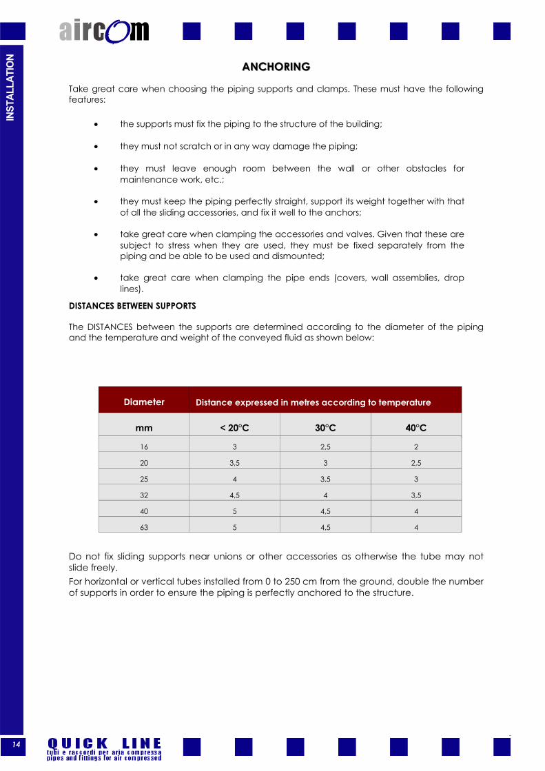
ANCHORINGANCHORING
Take great care when choosing the piping supports and clamps. These must have the following features:
• the supports must fix the piping to the structure of the building;
• they must not scratch or in any way damage the piping;
• they must leave enough room between the wall or other obstacles for maintenance work, etc.;
• they must keep the piping perfectly straight, support its weight together with that of all the sliding accessories, and fix it well to the anchors;
• take great care when clamping the accessories and valves. Given that these are subject to stress when they are used, they must be fixed separately from the piping and be able to be used and dismounted;
• take great care when clamping the pipe ends (covers, wall assemblies, drop lines).
DISTANCES BETWEEN SUPPORTS
The DISTANCES between the supports are determined according to the diameter of the piping and the temperature and weight of the conveyed fluid as shown below:
Do not fix sliding supports near unions or other accessories as otherwise the tube may not slide freely. For horizontal or vertical tubes installed from 0 to 250 cm from the ground, double the number of supports in order to ensure the piping is perfectly anchored to the structure.
Diameter Distance expressed in metres according to temperature
mm < 20°C 30°C 40°C
16 3 2,5 2
20 3,5 3 2,5
25 4 3,5 3
32 4,5 4 3,5
40 5 4,5 4
63 5 4,5 4
INST
ALLA
TIO
N

15

16
ASSEMBLY INSTRUCTIONS

17
THE ABSCENCE OR NOT SUITABLE EXECUTION FOR THAT ACTION COMPROMISES THE INSERTION OF THE TUBE INTO THE SOCKET.
ASSE
MBL
Y IN
STRU
CTIO
NS
The Aircom “QUICK LINE” series of unions can be connected both to the aluminium tube and the rigid PVC tube of the “CLASSIC” series. Assembly is extremely quick and easy and does not require expensive and complicated equipment. Just a few steps are required to fit a joint.
Chamfer carefully the external edge of the cut and remove any burrs and/or cutting residue along the inside edge as indicated in the pictures below or with instruments fitting to the purpose. Remove any cutting residue, dust, and swarfs from the inside of the tube in order to prevent future problems with the compressed air equipment.
2
1 After checking the surface of the tube (there must be no relevant scoring, abrasions, dents that could cause leaks), make a clean, straight cut to the required size. Cut the tube as near as possible to a right-angle (90° compared with the axis of the tube).
YOU MUST ALWAYS INSPECT THE PRESENCE OF ALL COMPONENTS AND THEIR CORRECT INSERTION
Union nut
Clip-ring Bush O-ring Gasket
Body
!

18
AIRCOM “QUICK LINE” system joints do not require waiting times after installation; the system can be pressurised immediately. After raise steam the system, control the shutting of all nuts and in case tighten them.
3
6
7
Tighten the ring nut of the union without forcing it excessively: reduce the distance between the body and the ring nut in the area indicated by the arrow.
4 Unscrew the ring nut by half a turn: this will increase the distance between the body and the ring nut in the area indicated by the arrow.
Fully tighten the ring nut. Sizes from d 20 to d 25 can normally be tightened by hand. Larger diameters can be tightened by hand and then with an appropriately sized pin wrench.
5 Fit the tube into the union and push until it comes to rest against the stop. To simplify this operation, grease the end of the tube and/or the contact surface of the O-Ring with Vaseline or other slip agents.
Do not use slip agents, oil or grease unless you are sure they are compatible. IF IN DOUBT, ASK US!
ASSE
MBL
Y IN
STRU
CTIO
NS

19
SIZING TABLES

20
INDEX OF SIZING TABLESINDEX OF SIZING TABLES
SIZI
NG T
ABLE
S
Description Code Page
Tubo Alluminio Alluminium line pipe / Tubo Línea Aluminium / Aluminium Line Rohrleitungen AIRTUAL 18
Doppia curva Double Bend / Doble Curva / Rohrleitungen AIRSCI 18
Manicotto f/f Socket / Manguito / Muffe AIRMA10 18
Gomito a 90° f/f 90° Elbow / Codo de 90° / 90° Kniestück AIRGO9010 18
Gomito a 45° f/f 45° Elbow / Codo de 45° / 45° Kniestück AIRGO4510 18
Calotta f End Cap / Final de Línea / Rohrleitungsende AIRCA10 19
Bocchettone di passaggio ottone Brass Adapter Union / Boca de paso en latón / Füllstutzen, Innengewinde/
Innengewinde AIRBP10 19
Raccordo maschio f/m Union male thread / Unión macho / Aschlußzapfen, Innen/Innengewinde,
Körper aus Messing AIRMN10 20
Raccordo maschio corpo ottone Nipple Socket - Brass Body m / Unión macho – cuerpo en latón / Anschluß-
zapfen, Aussengewinde AIRMNM10 20
Raccordo femmina f/f corpo ottone Nipple Socket f Brass Body f / Unión hembra F/F cuerpo en latón /
Aschlußzapfen, Innen/Innengewinde, Körper aus Messing AIRMPM10 20
Ti a 90° f/f/f 90° Bend / Te de 90° / 90° T-Stück AIRTE10 20
Ti a 90° ridotto f/f Reducing Tee / Ti reducido / Reduzierstück AIRTR10 20
Riduzione m/f/f Reducing / Reducción M/F/F / Reduzierstück, Aussengewinde/Innengewinde/
Innengewinde AIRRID10 21
Valvola sfera PP Quick Line Ball Cock / Válvula de bola Quick Line PP / PP Quick Line Kugel-
hahn AIRVA10 21
Presa di derivazione rapida Quick branch plug / Toma rápida de derivación / Schnellstichanschlusszap-
fen, Aussengewinde, Körper aus Messing AIRDER10 21
Presa di derivazione rapida filettata Quick branch plug ,f thread, brass / Toma rápida de derivación fileteada F
latón / Anschlußzapfen, Aussengewinde AIRDERFF 21

21
Tubo linea Alluminium Alluminium line pipe / Tubo Línea Aluminium / Aluminium Line Rohrleitungen
d Code Pack Mt/bar Thickness gr/m
20 AIRTUAL020 40 4 1,5 235
25 AlRTUAL025 40 4 1,5 299
32 AIRTUAL032
20 4
1,5 388 AIRTUAL6032 6
40 AIRTUAL040
20 4
645 AIRTUAL6040 6
50 AIRTUAL050 12 6 2
63 AIRTUAL063 12 6 2 1050
2
Doppia curva Double Bend / Doble Curva / Rohrleitungen
D Dn Code Pack Thickness Weight Kg/m
D int
20 AIRSCI020 5
25 AIRSCI025 5
Manicotto Socket / Manguito / Muffe
d Code Pack E H Gr
20 AIRMA10020 5 42 91 72
25 AlRMA10025 5 48 92 91
32 AIRMA10032 5 60 104 155
40 AIRMA10040 5 75 120 280
63 AIRMA10063 5
50 AIRMA10050 5
Gomito a 90° 90° Elbow / Codo de 90° / 90° Kniestück
d Code Pack E H Gr
20 AIRGO9010020 5 42 56 76
25 AlRGO9010025 5 48 58 97
32 AIRGO9010032 5 60 68 160
40 AIRGO9010040 5 75 82 300
63 AIRGO9010063 5
50 AIRGO9010050 5
Gomito a 45° 45° Elbow / Codo de 45° / 45° Kniestück
d Code Pack E H Gr
20 AIRGO4510020 5 42
25 AlRGO4510025 5 48
32 AIRGO4510032 5 60
40 AIRGO4510040 5 75
63 AIRGO4510063 5
50 AIRGO4510050 5
SIZI
NG T
ABLE
S

22
Bocchettone di passaggio ottone Brass Adapter Union / Boca de paso en latón / Füllstutzen, Innengewinde/Innengewinde
d Code Pack E H G gr
25x3/4” AIRBP10025068 2
40x1.1/4” AIRBP10040108 2
50x1.1/2” AIRBP10050128 2
63x2” AIRBP10063168 2
20x1/2” AIRBP10020048 2
32x1” AIRBP10032088 2
Calotta f End Cap / Final de Línea / Rohrleitungsende
d Code Pack E H G gr
20 AIRCA10020 5
25 AIRCA10025 5
32 AIRCA10032 5
40 AIRCA10040 5
50 AIRCA10050 5
63 AIRCA10063 5
Raccordo maschio f/m Union male thread / Unión macho / Aschlußzapfen, Innen/Innengewinde, Körper aus Messing
dxg Code Pack E H G gr
20x1/2” AIRMN10020048 5 42 66 1/2” 41
25x1/2” AIRMN10025048 5 48 67 1/2” 52
25X3/4” AIRMN10025068 5 48 68 3/4” 53
32X1” AIRMN10032088 5 60 74 1” 90
40X1” AIRMN10040088 5 75 84 1” 142
40X1.1/4” AIRMN10040108 5 75 89 1.1/4” 162
63X2” AIRMN10063168 5
50x1.1/2” AIRMN10050128 5
SIZI
NG T
ABLE
S

23
Ti ridotto Reducing Tee / Ti reducido / Reduzierstück
d Code Pack E H Gr
32x25 AIRTR10032025 5 42 50 36
40x25 AIRTR10040025 5 48 52 50
40x32 AIRTR10040032 5 60 56 81
50x32 AIRTR10050032 5 75 67 158
63x50 AIRTR10063050 5
50x40 AIRTR10050040 5
63x40 AIRTR10063040 5
25X20 AIRTR10025020 5
32X20 AIRTR10032020 5
40x20 AIRTR10040020 5
50x25 AIRTR10050025 5
63x25 AIRTR10063025 5
63x32 AIRTR10063032 5
Ti a 90° f/f/f 90° Bend / Te de 90° / 90° T-Stück
d Code Pack E H1 H2 Gr
20 AIRTE10020 5 42 112 56 113
25 AlRTE10025 5 48 120 60 146
32 AIRTE10032 5 60 140 70 254
40 AIRTE10040 5
63 AIRTE10063 5
50 AIRTE10050 5
Raccordo maschio f/m corpo ottone Nipple Socket - Brass Body m / Unión macho – cuerpo en latón / Anschlußzapfen, Aussengewinde
dxg Code Pack E H G gr
20x1/2” AIRMNM10020048 5 42 66 1/2” 41
25X3/4” AIRMNM10025068 5 48 68 3/4” 53
32X1” AIRMNM10032088 5 60 74 1” 90
40X1.1/4” AIRMNM10040108 5 75 89 1.1/4” 162
50x1.1/2” AIRMNM10050128 5
63X2” AIRMNM10063168 5
Disponibile su richiesta con filetto NPT - NPT threaded by request
Raccordo femmina f/f corpo ottone Nipple Socket f Brass Body f / Unión hembra F/F cuerpo en latón / A-schlußzapfen, Innen/Innengewinde, Körper aus Messing
dxg Code Pack E H g gr
20x1/2” AIRMPM10020048 10 42 64 !/2” 43
25X3/4” AIRMPM10025068 10 48 66 3/4” 57
32X1” AIRMPM10032088 10 60 70 1” 93
40X1.1/4” AIRMPM10040108 10 75 79 1.1/4” 158
63X2” AIRMPM10063168 5
50x1.1/2” AIRMNM10050128 10
Disponibile su richiesta con filetto NPT - NPT threaded by request
SIZI
NG T
ABLE
S

24
Presa di derivazione rapida Quick branch plug / Toma rápida de derivación / Schnellstichanschluss-zapfen, Aussengewinde, Körper aus Messing
d Code Pack E1 E2 H1 H2 gr
25X20 AIRDER10025020 5
32X20 AIRDER10032020 5
40X20 AIRDER10040020 5
40x25 AIRDER10040025 5
50x20 AIRDER10050020 5
63x20 AIRDER10063020 5
63x25 AIRDER10063025 5
63x32 AIRDER10063032 5
50x25 AIRDER10050025 5
d Code Pack E1 E2 H1 H2 gr 1/2” AIRVA10048 2
3/4” AIRVA10068 2
1” AIRVA10088 2
1.1/4” AIRVA100108 2
1.1/2” AIRVA10128 2
2” AIRVA10168 2
Valvola sfera PP Quick Line Ball Cock / Válvula de bola Quick Line PP / PP Quick Line Kugelhahn
Riduzione m/f/f Reducing / Reducción M/F/F / Reduzierstück, Aussengewinde/Innengewinde/Innengewinde
d Code Pack E1 E2 H1 H2 gr
25X20 AIRRID10025020 5
32X25 AIRRID10032025 5
40x32 AIRRID10040032 5
50x40 AIRRID10050040 5
63x50 AIRRID10063050 5
Presa di derivazione rapida filettata ottone Quick branch plug ,f thread, brass / Toma rápida de derivación fileteada F latón / Anschlußzapfen, Aussengewinde
d Code Pack E1 E2 H1 H2 gr 25x1/2” AIRDERFF025048 5
32x1/2” AIRDERFF032048 5
40x1/2” AIRDERFF040048 5
40x3/4” AIRDERFF040068 5
50x1/2” AIRDERFF050048 5
63x1/2” AIRDERFF063048 5
63x3/4” AIRDERFF063068 5
63x1” AIRDERFF063088 5
50x3/4” AIRDERFF050068 5
Disponibile su richiesta con filetto NPT - NPT threaded by request
SIZI
NG T
ABLE
S

25
DESIGN AND TESTING

26
1. GENERAL
The need for continuous developments, expansions and modifications to factory production lay-outs, together with evolutions in production technology with a strong emphasis on automation, require flexible and generously sized compressed air systems to be installed. 2. VIBRATIONS
Similarly to other energy sources, compressors produce vibrations that can damage the system. Never connect rigid AIRCOM tubes to the compressor; use hoses instead. If tubes must be connected to sources of vibrations, isolate them with flexible supports. 3. UV RADIATION
QUICK LINE UNIONS Similarly to all thermoplastics, the engineering polymers used for the unions are sensitive to direct UV radiation (direct exposure to sunlight), while they withstand indirect UV radiation (behind a window or other protective shield). For outdoor installation and all other cases of direct exposure to UV radiation, shield the unions (anti-UV paint, lagging, aluminium film, etc.). AIRCOM Aluminium tube The aluminium tube offers excellent UV resistance and can therefore be installed outdoors without any special protection. AIRCOM Classic tube If the piping is exposed to direct UV radiation, or it installed is outdoors, protect it with paint or another solid UV barrier (lagging, discharge tube, aluminium film). 4. SHOCK PROTECTION
Though the piping conveying compressed air must legally be fixed at least 2.5 metres from the ground, thereby making it unlikely to be hit, if the AIRCOM system is installed at lower heights, even for short distances, it must be suitably protected as, though it is flexible, AIRCOM piping cannot withstand violent impacts, especially from sharp points or cutting edges. 5. COLOUR
Pursuant to the UNI 5634-65 or NF A 571 standards, piping conveying compressed air must be painted light-blue. The AIRCOM Classic system is made from light-blue pigmented plastic and therefore does not require painting after installation or throughout the lifetime of the system; the AIRCOM Aluminium system is powder electro-painted light-blue and offers excellent resistance to corrosion. 6. SOURCES OF HEAT
AIRCOM Aluminium tube The Aluminium tube is more resistant than the Classic tube and can withstand temperatures up to 80 °C. The previous points also apply. AIRCOM Classic tube As indicated in the Pressure/temperature table, the AIRCOM System is made from a thermoplastic material and cannot withstand temperatures of over 60°C. It should therefore not be used near heat sources that reach or exceed this limit unless it is suitably protected.
DESI
GN
AND
TEST
ING

27
bar 16 20 25 32 40 63
1 195 230 420 820 1.480 5.120
3 530 620 1.160 2.240 4.160 12.420
5 860 1.010 1.890 3.640 6.430 21.500
7 1.140 1.360 2.560 4.960 9.100 29.870
10 1.630 2.050 3.840 7.350 13.600 45.300
12 2.100 2.450 4.650 8.650 15.700 55.800
16 2.800 3.250 6.200 10.900 18.600 71.400
MAXIMUM FLOW RATE L/M (SRA) Diameter of tube
SIZING
The main line is a closed loop system. The lines should slightly incline downwards (2‰) towards a condensation collector and drain. The piping should be large enough to cater for the maximum air flow required for the rated operating pressure, in order to minimise pressure drops that are simply a waste of energy. The maximum quantity of air required for each drop line is based on maximum consumption. Each drop line, multiplied by a factor (between > 0.1 and 1) representing the frequency of use of the connected equipment, will give average consumption. The sum of the average consumption of all the drop lines will give the maximum air flow required for the main line. A percentage is added to this value for prudential reasons and future growth requirements. After obtaining the maximum air flows required for each drop line and for the main distribution line, the sizing of each pipe can easily be calculated from the tables.
Elements for calculating flow rates
The friction coefficient of the AIRCOM Systems offers much higher rates of flow than traditional products. The following table shows the rates of flow in SRA – Standard Reference Atmosphere - at 20° C in litres/minute for a pressure drop of 2.5% every 100 metres.
DESI
GN
AND
TEST
ING

28
NORMOGRAM FOR DETERMINING DIAMETER, FLOW RATE, PRESSURE DROP AND PRESSURE
1. Calculating the (external) diameter of the tube according to pressure, flow rate and permitted pressure drop:
• draw a straight line from the pressure value (C axis) to the pressure drop value (A axis) meeting the R axis in X;
• draw a straight line from the flow rate value (axis A) to X intersecting the B axis on the diameter to use;
2. Calculating the flow rate according to diameter, pressure, and permitted pressure drop:
• draw a straight line from the pressure drop value (A axis) to the pressure value (C axis) meeting R in X;
• draw a straight line from X to the diameter value (B axis) and a straight line intersecting the A axis on the flow rate value;
3. Calculating the pressure drop according to diameter, pressure, and flow rate:
• draw a straight line from the flow rate value (A axis) to the diameter value (B axis) intersecting the R axis in X;
• draw a straight line from X to the pressure value (C axis) intersecting the A axis on the pressure drop value.
The flow rate is expressed in SRA = real flow rate of effective pressure (P) x absolute pressure (P+1) in bar.
273 288
flow rate at 0°C = flow rate at 15°C x Temperature correction factor:
NORMOGRAM at 15°C
DESI
GN
AND
TEST
ING

29
Ext. diam of tube
Coup. sleeve and union 90° elbow 45° elbow Ti
in line Ti in
deriv. Single
reducer Double reducer 180° curve
16 0,1 0,3 0,15 0,1 0,7 0,45 0,55 0,25
20 0,15 0,4 0,2 0,15 0,85 0,55 0,65 0,35
25 0,2 0,5 0,25 0,15 1,05 0,7 0,9 0,45
32 0,25 0,6 0,3 0,2 1,35 0,9 1,15 0,55
40 0,3 0,8 0,4 0,25 1,7 1,1 1,4 -
50 0,4 0,95 0,5 0,35 2,15 1,35 1,7 -
63 0,5 1,25 0,6 0,45 2,7 1,7 2,3 -
PRESSURE DROPS OF UNIONS Equivalent length of tube in metres
The pressure drops in piping are caused by several factors: • Friction in piping • Changes of direction and curves • Obstructions (valves, etc.) • Gradual or sudden changes in cross-sections
It is therefore necessary to use equivalent lengths in tubes of the same diameter for all types of un-ions; these will be added to the length of the tube when calculating the design length “L”.
DESI
GN
AND
TEST
ING

30
TESTING
All the articles in the AIRCOM System are produced according to European legislation, they are tested during all the phases of the production process and afterwards. All products are guaranteed for use within the limits indicated in this technical document and satisfy the ESR (Essential Safety Requirements) pursuant to directive 97/23/EC PED. The installations and systems produced with the AIRCOM System are also guaranteed as long as the products are used and mounted according to the present specifications and limits. During installation and afterwards certain checks and final testing should be performed. 1. INSPECTION After assembly, check that there are no faults, knocks, cuts, abrasions and make sure that the clamps and the line assembly comply with design specifications. In the event of problems, promptly replace the faulty parts or those parts that do not comply with design specifications. 2. AIR LEAK TESTING Immediately after the last joint 3. PRESSURE TESTING Pressure tests are performed with water at a pressure of least 1.5 times the maximum planned or designed operating pressure. Any components (valves, reducers, filters etc.) with lower test pressures should be appropriately isolated. The “pneumatic” pressure test can be performed at values ranging from 1.2 to 1.5 times operating pressure, but only if the following conditions are respected: a. When the layout of the system does not allow it to be completely filled with water. b. When the system is working, it must contain no traces of the test liquid. Pneumatic tests should be performed as follows: a. The test fluid must not be a flammable or toxic gas (nitrogen is better than air). b. Before reaching the planned test pressure, perform a preliminary test up to a maximum of 1.5
bar in order to identify any leaks and/or incomplete or imperfect joints in advance. After performing the checks and making the relative adjustments, keep the pressure at 1.5 bar and wait at least 5 minutes before increasing it.
For both the above test methods, increase the pressure gradually and constantly (1 bar every 4÷6 seconds) until you reach half the test pressure. Then slowly increase the pressure by “steps” of about one tenth of the maximum test value, waiting 5÷10 seconds every time. Once the test pressure is reached, it must remain constant (without any appreciable drops) for at least 10 minutes. 4. START-UP After performing the above procedures, clean and dry the system with compressed air, leaving one or more points in the system open in order to eliminate all the foreign bodies and dry the system. After the first 48 to 96 hours of operation, check all the joints and make sure all the ring nuts are tight as these may have loosened due to the settling of the components.
DESI
GN
AND
TEST
ING

31
C015 QL EN rev. 0
AIRCOM srl via Garibaldi 65 - 16040 Ne (GE) phone +39 0185 337691 fax +39 0185 337693 www.aircomsystem.com [email protected]