C S C StormTech Construction Guide A division of D C · Detention • Retention • Water Quality...
6
Detention • Retention • Water Quality A division of StormTech Construction Guide REQUIRED MATERIALS AND EQUIPMENT LIST • Acceptable fill materials per Table 1 • Woven and non-woven geotextiles • StormTech solid end caps and pre-cored end caps • StormTech chambers • StormTech manifolds and fittings IMPORTANT NOTES: A. This installation guide provides the minimum requirements for proper installation of chambers. Non-adherence to this guide may result in damage to chambers during installation. Replacement of damaged chambers during or after backfilling is costly and very time consuming. It is recommended that all installers are familiar with this guide, and that the contractor inspects the chambers for distortion, damage and joint integrity as work progresses. B. Use of a dozer to push embedment stone between the rows of chambers may cause damage to chambers and is not an acceptable backfill method. Any chambers damaged by using the “dump and push” method are not covered under the StormTech standard warranty. C. Care should be taken in the handling of chambers and end caps. Avoid dropping, prying or excessive force on chambers during removal from pallet and initial placement. SC-310/SC-740/DC-780 Requirements for System Installation Excavate bed and prepare subgrade per engineer's plans. Place non-woven geotextile over prepared soils and up excavation walls. Install underdrains if required. Place clean, crushed, angular stone foundation 6" (150 mm) min. Compact to achieve a flat surface. Call StormTech at 888.892.2694 for technical and product information or visit www.stormtech.com 1
-
Upload
truonglien -
Category
Documents
-
view
215 -
download
0
Transcript of C S C StormTech Construction Guide A division of D C · Detention • Retention • Water Quality...

Detention • Retention • Water Quality
A division ofStormTech Construction GuideREQUIRED MATERIALS AND EQUIPMENT LIST• Acceptable fill materials per Table 1• Woven and non-woven geotextiles
• StormTech solid end caps and pre-cored end caps• StormTech chambers• StormTech manifolds and fittings
IMPORTANT NOTES:
A. This installation guide provides the minimum requirements for proper installation of chambers. Non-adherence to this guide may result in damage to chambersduring installation. Replacement of damaged chambers during or after backfilling is costly and very time consuming. It is recommended that all installers are familiarwith this guide, and that the contractor inspects the chambers for distortion, damage and joint integrity as work progresses.
B. Use of a dozer to push embedment stone between the rows of chambers may cause damage to chambers and is not an acceptable backfill method. Any chambersdamaged by using the “dump and push” method are not covered under the StormTech standard warranty.
C. Care should be taken in the handling of chambers and end caps. Avoid dropping, prying or excessive force on chambers during removal from pallet and initial placement.
SC-310/SC-740/DC-780
Requirements for System Installation
Excavate bed and prepare subgrade perengineer's plans.
Place non-woven geotextile over prepared soilsand up excavation walls. Install underdrains ifrequired.
Place clean, crushed, angular stone foundation 6" (150 mm) min. Compact to achieve a flat surface.
Call StormTech at 888.892.2694 for technical and product information or visit www.stormtech.com 1

Manifold, Scour Fabric and Chamber Assembly
Install manifolds and lay out woven scour geo textile at inlet rows [min. 12.5 ft (3.8 m)] at each inlet end cap. Place a continuous piece (no seams, double layer) along entire length ofIsolator® Row(s).
Align the first chamber and end cap of eachrow with inlet pipes. Contractor may choose topostpone stone placement around end chambersand leave ends of rows open for easy inspectionof chambers during the backfill process.
Construct the chamber bed by overlapping thechambers lengthwise in rows. Attach chambers byoverlapping the end corrugation of one chamber onto the end corrugation of the last chamber in the row.Be sure that the chamber placement does notexceed the reach of the construction equipmentused to place the stone.
Lift the end of the chamber a few inches off theground. With the curved face of the end cap facingoutward, place the end cap into the chamber’s endcorrugation.
24" (600 mm) inlets are the maximum size that can fitinto a SC-740/DC-780 end cap and must be prefabri-cated with a 24" (600 mm) pipe stub. SC-310 cham-bers with a 12" (300 mm) inlet pipe must use aprefabricated end cap with a 12" (300 mm) pipe stub.
Drape a strip of ADS non-woven geotextile over therow of chambers (not required over DC-780). This isthe same type of non-woven geotextile used as aseparation layer around the angular stone of theStormTech system.
Attaching the End Caps Prefabricated End Caps Isolator Row
2

Call StormTech at 888.892.2694 for technical and product information or visit www.stormtech.com 3
Initial embedment shall be spotted along the centerline of the chamber evenlyanchoring the lower portion of the chamber. This is best accomplished with astone conveyor or excavator reaching along the row.
No equipment shall be operated on the bed at this stage of the installation.Excavators must be located off the bed. Dump trucks shall not dump stonedirectly on to the bed. Dozers or loaders are not allowed on the bed at this time.
Initial Anchoring of Chambers – Embedment Stone
12" (300 mm)MAX.
Perimeter stone must be brought up evenly with chamber rows. Perimetermust be fully backfilled, with stone extended horizontally to the excavation wall.
Backfill of Chambers – Embedment Stone
Backfill chambers evenly. Stone column height should never differ by more than12” (300 mm) between adjacent chamber rows or between chamber rows andperimeter.
UNEVEN BACKFILL EVEN BACKFILL PERIMETER NOT BACKFILLED PERIMETER FULLY BACKFILLED
Call StormTech at 888.892.2694 for technical and product information or visit www.stormtech.com 4
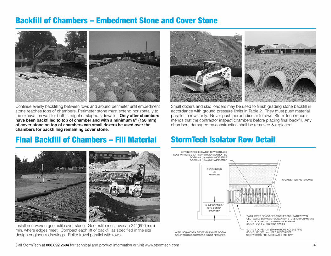
Final Backfill of Chambers – Fill Material
Install non-woven geotextile over stone. Geotextile must overlap 24" (600 mm)min. where edges meet. Compact each lift of backfill as specified in the sitedesign engineer’s drawings. Roller travel parallel with rows.
StormTech Isolator Row Detail
Small dozers and skid loaders may be used to finish grading stone backfill inaccordance with ground pressure limits in Table 2. They must push materialparallel to rows only. Never push perpendicular to rows. StormTech recom-mends that the contractor inspect chambers before placing final backfill. Anychambers damaged by construction shall be removed & replaced.
Backfill of Chambers – Embedment Stone and Cover Stone
Continue evenly backfilling between rows and around perimeter until embedmentstone reaches tops of chambers. Perimeter stone must extend horizontally tothe excavation wall for both straight or sloped sidewalls. Only after chambershave been backfilled to top of chamber and with a minimum 6" (150 mm)of cover stone on top of chambers can small dozers be used over thechambers for backfilling remaining cover stone.

Call StormTech at 888.892.2694 for technical and product information or visit www.stormtech.com 5
Table 1 – Acceptable Fill Materials
Material Location Description AASHTO M43 Compaction/Density Designation1 Requirement
PLEASE NOTE:1. The listed AASHTO designations are for gradations only. The stone must also be clean, crushed, angular. For example, a
specification for #4 stone would state: “clean, crushed, angular no. 4 (AASHTO M43) stone”. 2. StormTech compaction requirements are met for ‘A’ location materials when placed and compacted in 6” (150 mm) (max) lifts using
two full coverages with a vibratory compactor.3. Where infiltration surfaces may be comprised by compaction, for standard installations and standard design load conditions, a flat
surface may be achieved by raking or dragging without compaction equipment. For special load designs, contact StormTech forcompaction requirements.
Figure 2 – Fill Material Locations
D Final Fill: Fill Material for layer ‘D’starts from the top of the ‘C’ layer to thebottom of flexible pavement or unpavedfinished grade above. Note that the pave-ment subbase may be part of the ‘D’ layer.
C Initial Fill: Fill Material for layer‘C’ starts from the top of the embedmentstone (‘B’ layer) to 18" (450 mm) abovethe top of the chamber. Note thatpavement subbase may be part of the‘C’ layer.
B Embedment Stone: Embed-ment Stone surrounding chambers fromthe foundation stone to the ‘C’ layer above.
A Foundation Stone: FoundationStone below the chambers from the sub-grade up to the foot (bottom) of the chamber.
Any soil/rock materials, nativesoils or per engineer's plans.Check plans for pavementsubgrade requirements.
Granular well-graded soil/aggregatemixtures, <35% fines or processedaggregate. Most pavement subbasematerials can be used in lieu of thislayer.
Clean, crushed, angular stonenominal size distribution
Clean, crushed, angular stone,nominal size distribution
Prepare per site design engineer’s plans. Pavedinstallations may have stringent material andpreparation requirements.
Begin compaction after min. 12" (300 mm) of materialover the chambers is reached. Compact additionallayers in 6" (150 mm) max. lifts to a min. 95% Proctordensity for well-graded material and 95% relativedensity for processed aggregate materials. Rollergross vehicle weight not to exceed 12,000 lbs (53 kN).Dynamic force not to exceed 20,000 lbs (89 kN)
No compaction required.
Place and compact in 6" (150 mm) lifts using two fullcoverages with a vibratory compactor.2, 3
N/A
AASHTO M45A-1, A-2-4, A-3
or AASHTO M431
3, 357, 4, 467, 5, 56, 57, 6,67, 68, 7, 78, 8, 89, 9, 10
AASHTO M431
3, 357, 4, 467, 5, 56, 57
AASHTO M431
3, 357, 4, 467, 5, 56, 57
Figure 1 – Inspection Port Detail

NOTES:1. 36" (900 mm) of stabilized cover materials over the chambers is required
for full dump truck travel and dumping.
2. During paving operations, dump truck axle loads on 18” (450 mm) ofcover may be necessary. Precautions should be taken to avoid ruttingof the road base layer, to ensure that compaction requirements havebeen met, and that a minimum of 18” (450 mm) of cover exists overthe chambers. Contact StormTech for additional guidance onallowable axle loads during paving.
3. Ground pressure for track dozers is the vehicle operating weightdivided by total ground contact area for both tracks. Excavators willexert higher ground pressures based on loaded bucket weight andboom extension.
4. Mini-excavators (< 8,000lbs/3,628 kg) can be used with at least 12”(300 mm) of stone over the chambers and are limited by themaximum ground pressures in Table 2 based on a full bucket atmaximum boom extension.
5. Storage of materials such as construction materials, equipment,spoils, etc. should not be located over the StormTech system. Theuse of equipment over the StormTech system not covered in Table 2(ex. soil mixing equipment, cranes, etc) is limited. Please contactStormTech for more information.
6. Allowable track loads based on vehicle travel only. Excavators shallnot operate on chamber beds until the total backfill reaches 3 feet(900 mm) over the entire bed.
ADS “Terms and Conditions of Sale” are available on the ADS website,www.ads-pipe.com.Advanced Drainage Systems, the ADS logo, and the green stripe are registeredtrademarks of Advanced Drainage Systems. StormTech® and the Isolator® Row are registered trademarks of StormTech, Inc#090113 07/15
©2015 Advanced Drainage Systems, Inc.
Call StormTech at 888.892.2694 for technical and product information or visit www.stormtech.com 6
Table 2 – Maximum Allowable Construction Vehicle Loads5
D Final FillMaterial
36" [900]Compacted
32,000 [142] 16,000 [71] 12" [305]18" [457]24" [610]30" [762]36" [914]
3420 [164]2350 [113]1850 [89]1510 [72]1310 [63]
38,000 [169]
24" [600]Compacted
32,000 [142] 16,000 [71] 12" [305]18" [457]24" [610]30" [762]36" [914]
2480 [119]1770 [85]1430 [68]1210 [58]1070 [51]
20,000 [89]
24" [600]Loose/Dumped
32,000 [142] 16,000 [71] 12" [305]18" [457]24" [610]30" [762]36" [914]
2245 [107]1625 [78]1325 [63]1135 [54]1010 [48]
20,000 [89]Roller gross vehicle weight not to
exceed 12,000 lbs. [53 kN]
18" [450] 32,000 [142] 16,000 [71] 12" [305]18" [457]24" [610]30" [762]36" [914]
2010 [96]1480 [71]1220 [58]1060 [51]950 [45]
20,000 [89]Roller gross vehicle weight not to
exceed 12,000 lbs. [53 kN]
12" [300] 16,000 [71] NOT ALLOWED 12" [305]18" [457]24" [610]30" [762]36" [914]
1540 [74]1190 [57]1010 [48]910 [43]840 [40]
12" [305]18" [457]24" [610]30" [762]36" [914]
1070 [51]900 [43]800 [38]760 [36]720 [34]
20,000 [89]Roller gross vehicle weight not to
exceed 12,000 lbs. [53 kN]
6" [150] 8,000 [35] NOT ALLOWED NOT ALLOWED
C Initial FillMaterial
B EmbedmentStone
Maximum Allowable Wheel Loads Maximum Allowable Track Loads6 Maximum Allowable Roller LoadsMaterial Fill Depth Max Axle Load Max Wheel Load Track Max Ground Max Drum WeightLocation over Chambers for Trucks for Loaders Width Pressure or Dynamic Force
in. [mm] lbs [kN] lbs [kN] in. [mm] psf [kPa] lbs [kN]
Table 3 – Placement Methods and Descriptions Material Placement Wheel Load Track Load Roller Load Location Methods/ Restrictions Restrictions Restrictions Restrictions See Table 2 for Maximum Construction LoadsD Final Fill
MaterialA variety of placement methods may beused. All construction loads must notexceed the maximum limits in Table 2.
36" (900 mm) minimumcover required for dumptrucks to dump over chambers.
C Initial FillMaterial
Excavator positioned off bed recom-mended. Small excavator allowed overchambers. Small dozer allowed.
Asphalt can be dumped intopaver when compactedpavement subbase reaches18" (450 mm) above top ofchambers.
Small LGP track dozers & skidloaders allowed to grade coverstone with at least 6" (150 mm)stone under tracks at all times.Equipment must push parallelto rows at all times.
Dozers to push parallel torows until 36" (900mm)compaced cover isreached.4
Use dynamic force of rolleronly after compacted filldepth reaches 12" (300 mm)over chambers. Roller travelparallel to chamber rows only.
Roller travel parallel to rowsonly until 36” (900 mm)compacted cover isreached.
B EmbedmentStone
No equipment allowed on bare cham-bers. Use excavator or stone conveyorpositioned off bed or on foundationstone to evenly fill around all cham-bers to at least the top of chambers.
No wheel loads allowed.Material must be placedoutside the limits of thechamber bed.
No tracked equipment isallowed on chambers until amin. 6" (150 mm) coverstone is in place.
No rollers allowed.
A FoundationStone
No StormTech restrictions. Contractor responsible for any conditions or requirements by others relative to subgrade bearingcapacity, dewatering or protection of subgrade.