C I V I C A 1 /(A '(0< 6( IV 68%0I77 A 5(9,6,211R '$7 ...
7
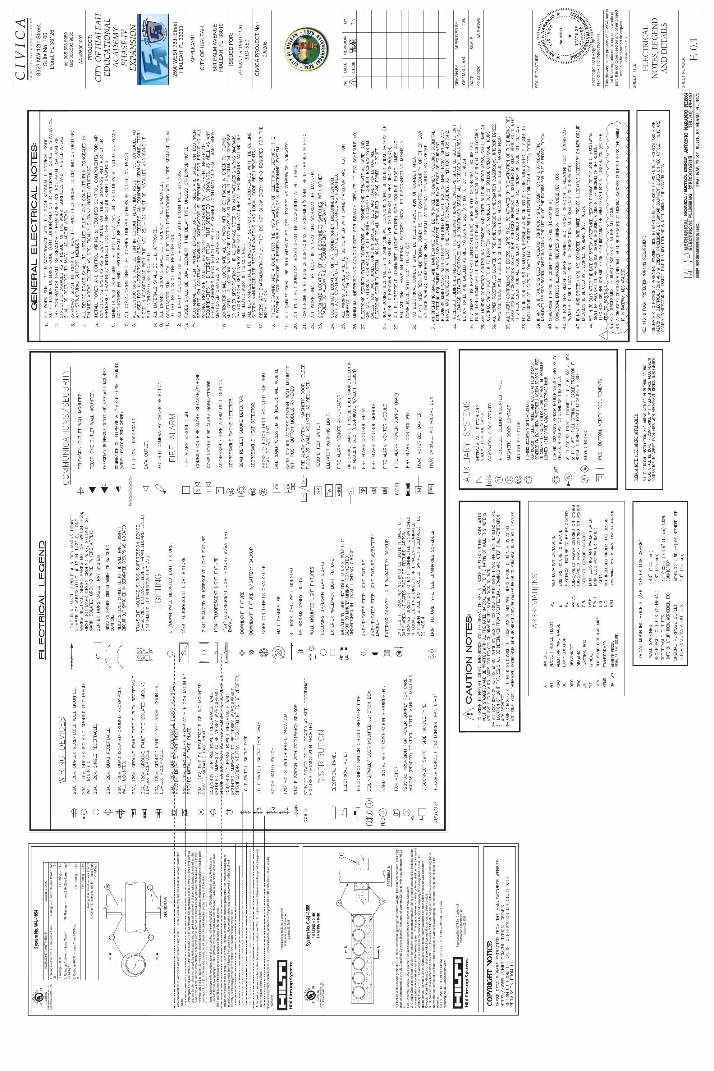
Hilti Firestop Systems System No. W-L-1054 SECTION A-A A Reproduced by HILTI, Inc. Courtesy of Underwriters Laboratories, Inc. January 23, 2015 A 1A 3 2 1B C C L A S S I F I E D 5 Classified by Underwriters Laboratories, Inc. to UL 1479 and CAN/ULC-S115 US $16,8/ $670 ( &$18/& 6 ) 5DWLQJV ² DQG +U 6HH ,WHPV DQG ) 5DWLQJV ² DQG +U 6HH ,WHPV DQG 7 5DWLQJ ² +U )7 5DWLQJ ² +U / 5DWLQJ DW $PELHQW ² /HVV 7KDQ &)0VT IW )+ 5DWLQJV ² DQG +U 6HH ,WHPV DQG / 5DWLQJ DW ) ² /HVV 7KDQ &)0VT IW )7+ 5DWLQJ ² +U )7+ 5DWLQJ ² +U / 5DWLQJ DW $PELHQW ² /HVV 7KDQ &)0VT IW / 5DWLQJ DW ) ² /HVV 7KDQ &)0VT IW • ••• • •••• ••• • • •••• •• • • •• •• ••• •• •••••• ••• •• • •• •• •• • •• • ••• • • •• •••• • •• • •••• ••• • • ••••• • •••• • ••• • •••• ••• • •• •••• • •• • •• ••• •••• • • ••• ••• • •• • • • • •••• • ••••• • • • • • • • • • • • • • • • • • • • • • • • • • • • • • • • • • • • • • • • • • • • • • • • • • • • • • • • • • • • • • • • • • • • • • • • • • • • • • • • • • • • • • • • • • • • • • • • • • • • • • • • • • • • • • • • • • • • • • • • • • • • • • • • • • • • • • • • • • • • • • • • • • • in the individual U300 or U400 Series Wall and Partition Designs in the UL Fire Resistance Directory and shall include the following construction features: • ••• •• • ••• •• • •••••• • •• • •• • •••• • •••••• ••• ••• • ••• • • • •••• • ••• ••••• • •••• • • • • ••••• • •••• • • • •••• • •••• ••• • •••••• ••• • • •• •• ••• ••• •••• • •• ••• • • •• • •••••••••••••••••••••••••••••••••••••••••••••••••••••••••••••••••••••••••••••••••••••••••••••••••••••••••••••••••••••••••••••••••••••••• lumber spaced 16 in. (406 mm) OC. Steel studs to be min 2-1/2 in. (64 mm) wide and spaced max 24 in. (610 mm) OC. When steel studs are used and the diam of opening exceeds the width of stud cavity, the opening shall be framed on all sides using lengths of steel stud installed between the vertical studs and screw-attached to the steel studs at each end. The framed opening in the wall shall be 4 to 6 in. (102 to 152 mm) wider and 4 to 6 in. (102 to 152 mm) higher than the diam of the penetrating item such that, when the penetrating item is installed in the opening, a 2 to 3 in. (51 to 76 mm) clearance is present between the penetrating item and the framing on all four sides. • ••• •• •• • •• • • •• ••• •• •• ••• •••• • •• • •••• •••••• •••••• • • ••• ••• •• • •• ••• ••• • • •• •• •••• • • •• • •• • • • •••• • • •• •• •• • •• • • •• •••• • •••• •••• • ••••• • • • • ••• ••••••••••••••••••••••••••••••••••••••••••••••••••••••••••••••••••••••••••••••••••••••••••••••••••••••••••••••••••••••••••••••••••••••• layers, fastener type and sheet orientation shall be as specified in the individual U300 or U400 Series Design in the UL Fire Resistance Directory. Max diam of opening is 32-1/4 in. (819 mm) for steel stud walls. Max diam of opening is 14-1/2 in. (368 mm) for wood stud walls. The F and FH Ratings of the firestop system are equal to the fire rating of the wall assembly. • ••• • •• • • • •• • • • ••• • •••• •• • • •• • •• •••••• •• • •••• • • • •••• •••• • •• • ••• •• • ••• ••• ••• • •• ••• • •••• • •• • ••••• ••••• ••• ••• • ••••• ••••• ••• •• ••• • ••••• ••• • •••••• • ••• • • • • • • • • • • • • • • • • • • • • • • • • • • • • • • • • • • • • • • • • • • • • • • • • • • • • • • • • • • • • • • • • • • • • • • • • • • • • • • • • • • • • • • • • • • • • • • • • • • • • • • • • • • • • • • • • • • • • • • • • • • • • • • • • • • • • • • • • • • • • • • • • • • • • • annular space shall be min 0 in. to max 2-1/4 in. (57 mm). Pipe may be installed with continuous point contact. Pipe, conduit or tubing may be installed at an angle not greater than 45 degrees from perpendicular. Pipe, conduit or tubing to be rigidly supported on both sides of wall assembly. The following types and sizes of metallic pipes, conduits or tubing may be used: • ••• •• • ••• •• • •• •• • • •• • ••• •••• • • •• • ••• •• • ••• •••• • ••• •••• •• • • • •• •• • ••• ••• • • ••• •••••• • ••• •• • ••••••••••••••••••••••••••••••••••••••••••••••••••••••••••••••••••••••••••••••••••••••••••• • ••••• • •• •• • •• •• • • •• • ••• •••• • • •• • ••• •• • ••• •••• • ••• ••••• •••• ••• • ••••• •••• • •• •• • •••••••••••••••••••••••••••••••••••••••••••••••••••••••••••••••••••••••••••••••• • ••• • • • • •••• •• • • •• ••• •••• • • •• • ••• •• • ••• •••• • ••• •••••• • ••• •• •••••• ••• • •• ••••••• • •• • •• ••• ••• •••• • • •• • ••••• •• • •••• • •••• • • • ••••••••••••••••••••••••••••••••••••••••••••••••••••••••••••••••••••••••••••••••••••••••••••••••••••••••••••••••••••••••••••• • ••• • • • • ••• • • •• • •• •• • • •• ••• •••• • • •• • ••• •• • ••• •••• • ••• •••• •• • •• ••• ••• • • ••• ••••• • • • •••• • •• • ••••••••••••••••••••••••••••••••••••••••••••••••••••••••••••••••••••••••••••••••••••••••••• • ••• • • • • ••• •• • •• •• • • •• ••• •••• • • •• • ••• •• • ••• •••• • ••• ••••• • • •• •••• ••• • • ••• ••••• • • • ••• •• • •••••••••••••••••••••••••••••••••••••••••••••••••••••••••••••••••••••••••••••••••••••••• • ••• •••••• • •• •• ••• • •••••• • •• ••• •••• •• • • •• • ••• •• •• •• •• ••• •••• • •• • •••• •••• • •••• •••••••• • •• ••• ••• • • ••• • •• ••• •• ••• • •• • • • •• •••••• •• •• ••• •• • •• ••• ••• •• ••• ••• • ••••••••••••••••••••••••••••••••••••••••••••••••••••••••••••••••••••••••••••••••••••••••••••••••••••••••••••••••••••••••••••••••••••••••••••••••••••••••••••• At the point or continuous contact locations between pipe and wall, a min 1/2 in. (13 mm) diam bead of fill material shall be applied at the pipe wall interface on both surfaces of wall. • •• • ••• • • • • • • • • •• • •• • • • •• • • • ••• •• •• • •• •• • •••• • •• •• • •• • • •• • • •• • ••• ••• • •• • • •• • • ••• •• • • ••• • ••• • • •• • •••••••••••••••••••••••••••••••••••••••••••••••••••••••••••••••••••••••••••••••••••••••••••••••••• * Indicates such products shall bear the UL or cUL Certification Mark for jurisdictions employing the UL or cUL Certification (such as Canada), respectively. System No. C-AJ-1388 SECTION A-A )ORRU RU :DOO $VVHPEO\ 0LQ LQ WKLFN UHLQIRUFHG OLJKWZHLJKW RU QRUPDO ZHLJKW SFI FRQFUHWH :DOO PD\ DOVR EH FRQVWUXFWHG RI DQ\ 8/ &ODVVLILHG &RQFUHWH %ORFNV 0D[ DUHD RI RSHQLQJ VT LQ ZLWK PD[ GLPHQVLRQ RI LQ 6HH &RQFUHWH %ORFNV &$=7 LQ WKH )LUH 5HVLVWDQFH 'LUHFWRU\ IRU QDPHV RI PDQXIDFWXUHUV &RQGXLW 2QH RU PRUH QRP LQ GLDP RU VPDOOHU VWHHO HOHFWULFDO PHWDOOLF WXELQJ RU VWHHO FRQGXLW WR EH LQVWDOOHG HLWKHU FRQFHQWULFDOO\ RU HFFHQWULFDOO\ ZLWKLQ WKH ILUHVWRS V\VWHP 7KH VSDFH EHWZHHQ FRQGXLWV RU WXEHV VKDOO EH PLQ LQ SRLQW FRQWDFW WR PD[ LQ 7KH DQQXODU VSDFH EHWZHHQ WKH FRQGXLW RU WXEH DQG SHULSKHU\ RI RSHQLQJ VKDOO EH PLQ LQ SRLQW FRQWDFW WR PD[ LQ &RQGXLW RU WXEH WR EH ULJLGO\ VXSSRUWHG RQ ERWK VLGHV RI IORRU RU ZDOO DVVHPEO\ &RQGXLW 1RP LQ GLDP RU VPDOOHU VWHHO HOHFWULFDO PHWDOOLF FRQGXLW RU VWHHO FRQGXLW )LOO 9RLG RU &DYLW\ 0DWHULDO )RDP 0LQ LQ WKLFNQHVV RI ILOO PDWHULDO DSSOLHG ZLWKLQ WKH DQQXOXV H[WHQGLQJ LQ DERYH WKH WRS VXUIDFH RI WKH IORRU RU ERWK VXUIDFHV RI ZDOO DQG RYHUODSSLQJ WKH FRQFUHWH LQ RQ DOO VLGHV RI WKH RSHQLQJ +,/7, &216758&7,21 &+(0,&$/6 ',9 2) +,/7, ,1& &3 )LUH )RDP %HDULQJ WKH 8/ &ODVVLILFDWLRQ 0DUN A Reproduced by HILTI, Inc. Courtesy of Underwriters Laboratories, Inc. January 23, 2002 F RATING = 2-HR T RATING = 0-HR A 1 2 3 Hilti Firestop Systems C C L A S S I F I E D 5 Classified by Underwriters Laboratories, Inc. to UL 1479 and CAN/ULC-S115 US ( (/(&75,&$/ 127(6 /(*(1' $1' '(7$,/6 <3 0*-(* 71 $6 6+2:1 )/25,'$ /,&(16( 3( $1721,2 1$5$1-2 3( 6+((7 180%(5 &23<5,*+76 7KLV GUDZLQJ LV WKH SURSHUW\ RI &,9,&$ DQG LV QRW WR EH UHSURGXFHG RU FRSLHG LQ ZKROH RU SDUW ,W LV QRW WR EH XVHG RQ DQ\ RWKHU SURMHFW DQG LV WR EH UHWXUQHG RQ UHTXHVW 6+((7 7,7/( 6($/6,*1$785( $33529(' %< 6&$/( '$7( '5$:1 %< 5(9,6,21 1R '$7( %< ,668(' )25 C I V I C A WHO ID[ CI7< 2) +IA/(A+ ('8CA7I21A/ ACA'(0< 3+A6(IV (;3A16I21 $33/,&$17 3(50I7 68%0I77A/ %I'6(7 $$ 352-(&7 &,9,&$ 352-(&7 1R &,7< 2) +,$/($+ 3$/0 $9(18( +,$/($+ )/ A 5 C + I 7 ( C 7 8 5 ( 8 5 % A 1 ' ( 6 I * 1 1: WK 6WUHHW 6XLWH 1R 'RUDO )/ :(67 WK 6WUHHW +,$/($+ )/
Transcript of C I V I C A 1 /(A '(0< 6( IV 68%0I77 A 5(9,6,211R '$7 ...
Hilt
i Fir
esto
p S
yste
ms
Syst
em N
o. W
-L-1
054
SECT
ION
A-A
A
Repr
oduc
ed by
HILT
I, Inc
. Cou
rtesy
ofUn
derw
riters
Labo
rator
ies, In
c.Ja
nuar
y 23,
2015
A
1A3 2
1B
C
CLASSI
F I
ED
Clas
sified
byUn
derw
riters
Labo
rator
ies, In
c.to
UL 14
79 an
d CAN
/ULC
-S11
5
US
••••••••••••••••••••••••••••••••••••••••••••••••••••••••••••••••••••••••••••••••••••••••••••••••••••••••••••••••••••••••••••••••••••••••••••••••••••••••••••••••••••••••••••••••••••••••••••••••••••••••••••••••••••••••••••••••••••••••••••••••••••••••••••••••••••••••••••••••••••••••••••••••••
in the
indiv
idual
U300
or U
400 S
eries
Wall
and P
artiti
on D
esign
s in t
he U
L Fire
Res
istan
ce D
irecto
ry an
d sha
ll inc
lude t
he fo
llowi
ng co
nstru
ction
featur
es:
••••••••••••••••••••••••••••••••••••••••••••••••••••••••••••••••••••••••••••••••••
••••••••••••••••••••••••••••••••••••••••••••••••••••••••••••••••••••••••••••••••••••••••••••••••••••••••••••••••••••••••••••••••••••••••••••••••••••••••••••••••••••••••••••••••••••••••••••
lumbe
r spa
ced 1
6 in.
(406
mm)
OC.
Stee
l stud
s to b
e min
2-1/2
in. (
64 m
m) w
ide an
d spa
ced m
ax 24
in. (
610 m
m) O
C. W
hen s
teel s
tuds a
reus
ed an
d the
diam
of op
ening
exce
eds t
he w
idth o
f stud
cavit
y, the
open
ing sh
all be
fram
ed on
all s
ides u
sing l
ength
s of s
teel s
tud in
stalle
dbe
twee
n the
vertic
al stu
ds an
d scre
w-att
ache
d to t
he st
eel s
tuds a
t eac
h end
. The
fram
ed op
ening
in th
e wall
shall
be 4
to 6 i
n. (1
02 to
152
mm) w
ider a
nd 4
to 6 i
n. (1
02 to
152 m
m) hi
gher
than
the d
iam of
the p
enetr
ating
item
such
that,
whe
n the
pene
tratin
g item
is in
stalle
d in t
heop
ening
, a 2
to 3 i
n. (5
1 to 7
6 mm)
clea
ranc
e is p
rese
nt be
twee
n the
pene
tratin
g item
and t
he fr
aming
on al
l four
side
s.••••••••••••••••••
••••••••••••••••••••••••••••••••••••
••••••••••••••••••••••••••••••••••••••••••••••••••••••••••••••••••••••••••••••••••••••••••••••••••••••••••••••••••••••••••••••••••••••••••••••••••••••••••••••••••••••••••••••••••••••••••••••••••••••••••••••••••••••
layer
s, fas
tener
type
and s
heet
orien
tation
shall
be as
spec
ified i
n the
indiv
idual
U300
or U
400 S
eries
Des
ign in
the U
L Fire
Res
istan
ceDi
recto
ry. M
ax di
am of
open
ing is
32-1
/4 in.
(819
mm)
for s
teel s
tud w
alls.
Max d
iam of
open
ing is
14-1
/2 in.
(368
mm)
for w
ood s
tud w
alls.
The F
and F
H Ra
tings
of th
e fire
stop s
ystem
are e
qual
to the
fire r
ating
of th
e wall
asse
mbly.
•••••••••••••••••••••••
•••••••••••••••••••••••••••••••••••••••••••••••••••••••••••••••••••••••••••••••••••••••••••••••••••••••••••••••••••••••••••••••••••••••••••••••••••••••••••••••••••••••••••••••••••••••••••••••••••••••••••••••••••••••••••••••••••••••••••••••••••••••••••••••••••••••••••••••
annu
lar sp
ace s
hall b
e min
0 in.
to ma
x 2-1
/4 in.
(57 m
m). P
ipe m
ay be
insta
lled w
ith co
ntinu
ous p
oint c
ontac
t. Pipe
, con
duit o
r tub
ing m
ay be
instal
led at
an an
gle no
t gre
ater t
han 4
5 deg
rees
from
perp
endic
ular.
Pipe
, con
duit o
r tub
ing to
be rig
idly s
uppo
rted o
n both
side
s of w
allas
semb
ly. T
he fo
llowi
ng ty
pes a
nd si
zes o
f meta
llic pi
pes,
cond
uits o
r tub
ing m
ay be
used
:••••••••••••••••••••••••••••••••••••••••
••••••••••••••••••••••••••••••••••••••••••••••••••••••••••••••••••••••••••••••••••••••••••••••••••••••••••••••••••••••••••••••••••••••••••••
•••••••••••••••••••••••••••••••••••••••
•••••••••••••••••••••••••••••••••••••••••••••••••••••••••••••••••••••••••••••••••••••••••••••••••••••••••••••••••••••••
••••••••••••
••••••••••••••••••••••••
•••••••••••••••••••••••••••••••••••••••••••••••••••••••••••••••••••••••
•••••••••••••••••••••••••••••••••••••••••••••••••••••••••••••••••••••••••••••••••••••••••••••••••••••••••••••••••••••••••••••••••••••••••
••••••••••••••••••••••••••••••••••••••••••
••••••••••••••••••••••••••••••••••••••••••••••••••••••••••••••••••••••••••••••••••••••••••••••••••••••••••••••••••••••••••••••••••••••••••
••••••••••••••••••••••••••••••••••••••••
••••••••••••••••••••••••••••••••••••••••••••••••••••••••••••••••••••••••••••••••••••••••••••••••••••••••••••••••••••••••••••••••••••••
•••••••••••••••••••••••••••••••••••
••••••••••
•••••••••••••••••••••••••••••••••••••••••••••••••••••••••••••••••••••••••••••••••••••••••••••••••••••••••••••••••••••••••••••••••••••••••••••••••••••••••••••••••••••••••••••••••••••••••••••••••••••••••••••••••••••••••••••••••••••••••••••••••••••••••••••••••••••••
At th
e poin
t or c
ontin
uous
conta
ct loc
ation
s betw
een p
ipe an
d wall
, a m
in 1/2
in. (
13 m
m) di
am be
ad of
fill m
ateria
l sha
ll be a
pplie
d at th
e pipe
wall
inter
face o
n both
surfa
ces o
f wall
.•••••••••
••••
••••••••
•••••••••••••••••••••••••
••••••••••••••••••••••••••
••••••••••••••••••••••••••••••••••••••••••••••••••••••••••••••••••••••••••••••••••••••••••••••••••••••••••••••••••••••••••
* Ind
icates
such
prod
ucts
shall
bear
the U
L or c
UL C
ertifi
catio
n Mar
k for
juris
dictio
ns em
ployin
g the
UL o
r cUL
Cer
tifica
tion (
such
as C
anad
a),
resp
ectiv
ely.
Syst
em N
o. C
-AJ-
1388
SECT
ION
A-A
A Repr
oduc
ed by
HILT
I, Inc
. Cou
rtesy
ofUn
derw
riters
Labo
rator
ies, In
c.Ja
nuar
y 23,
2002
F RA
TING
= 2-
HRT
RATI
NG =
0-HR
A
12 3
Hilt
i Fir
esto
p S
yste
ms
C
CLASSI
F I
ED
Clas
sified
byUn
derw
riters
Labo
rator
ies, In
c.to
UL 14
79 an
d CAN
/ULC
-S11
5
US
C I V
I C
A
CI
IA
ACA
IA
ACA
AIV
AI
I
IA
I
A
C
I
C
A
I

C I V
I C
A
CI
IA
ACA
IA
ACA
AIV
AI
I
IA
I
A
C
I
C
A
I

C I V
I C
A
CI
IA
ACA
IA
ACA
AIV
AI
I
IA
I
A
C
I
C
A
I

C I V
I C
A
CI
IA
ACA
IA
ACA
AIV
AI
I
IA
I
A
C
I
C
A
I

C I V
I C
A
CI
IA
ACA
IA
ACA
AIV
AI
I
IA
I
A
C
I
C
A
I

C I V
I C
A
CI
IA
ACA
IA
ACA
AIV
AI
I
IA
I
A
C
I
C
A
I

C I V
I C
A
CI
IA
ACA
IA
ACA
AIV
AI
I
IA
I
A
C
I
C
A
I