C-24 Classic Benchtop Incubator Shakercore.phmtox.msu.edu/Scheduling/ItemDocs/10/C24_Classic... ·...
43
C-24 Classic Benchtop Incubator Shaker MANUAL NO: M1247-0052 Revision E October 29, 2004 NEW BRUNSWICK SCIENTIFIC CO., INC. BOX 4005 • 44 TALMADGE ROAD • EDISON, NJ 08818-4005 Telephone: 1-732-287-1200 • 1-800-631-5417 Fax: 732-287-4222 • Telex: 4753012 NBSCO Internet: http://www.nbsc.com • E-mail: [email protected]
Transcript of C-24 Classic Benchtop Incubator Shakercore.phmtox.msu.edu/Scheduling/ItemDocs/10/C24_Classic... ·...
C-24 Classic Benchtop
Incubator Shaker MANUAL NO: M1247-0052
Revision E October 29, 2004
NEW BRUNSWICK SCIENTIFIC CO., INC.
BOX 4005 • 44 TALMADGE ROAD • EDISON, NJ 08818-4005 Telephone: 1-732-287-1200 • 1-800-631-5417 Fax: 732-287-4222 • Telex: 4753012 NBSCO Internet: http://www.nbsc.com • E-mail: [email protected]
2
THIS PAGE IS INTENTIONALLY BLANK
C-24 Classic Benchtop Incubator Shaker User’s Guide
3 INTERNATIONAL OFFICES: BELGIUM New Brunswick Scientific NV-SA Stationsstraat 180/4 3110 Rotselaar België/Belgique Tel: 32 (0)16 56 28 31 Fax: 32 (0)16 57 27 53 E-mail: [email protected]
GERMANY New Brunswick Scientific GmbH In Der Au 14 D-72622 Nürtingen Deutschland Tel: 49 (0)7022 932490 Fax: 49 (0)7022 32486 E-mail: [email protected]
CHINA New Brunswick Scientific Co., Inc. Room 1501, Xiangjiang Building, No. 18 Lane 1265, Zhongshan Road (W) Shanghai 200051, P.R. China Tel: 86 21 3223 0203 Fax: 86 21 6278 7182 E-mail: [email protected]
THE NETHERLANDS New Brunswick Scientific BV Kerkenbos 1101, 6546 BC Nijmegen P.O Box 6826, 6503 GH Nijmegen Nederland Tel: 31 (0)24 3717 600 Fax: 31 (0)24 3717 640 E-mail: [email protected]
FRANCE New Brunswick Scientific SARL 3, rue des Deux-Boules 75001 Paris France Tel: 33 (0)1 4026 2246 Fax: 33 (0)1 4026 5423 E-mail: [email protected]
UNITED KINGDOM New Brunswick Scientific (UK) Ltd. 17 Alban Park St. Albans, Herts. AL4 0JJ United Kingdom Tel: 44 (0)1727 853855 or 0800 581331 Fax: 44 (0)1727 835666 E-mail: [email protected] Web: www.nbsuk.co.uk
New Brunswick Scientific Co., Inc. User’s Guide

4
THIS PAGE IS INTENTIONALLY BLANK
C-24 Classic Benchtop Incubator Shaker User’s Guide
5
New Brunswick
WARNING! The C-24 Classic Benchtop Incubator Shaker must be operated as described in this manual. If guidelines are not followed, equipment damage can occur. Please read entire User’s Guide before attempting to use the Shaker.
Scientific Co., Inc. User’s Guide

6
THIS PAGE IS INTENTIONALLY BLANK
C-24 Classic Benchtop Incubator Shaker User’s Guide
7
Copyright Notice New Brunswick Scientific Company, Inc. Box 4005 44 Talmadge Road Edison, New Jersey 08818-4005
© Copyright 2004 New Brunswick Scientific Co., Inc.
All Rights Reserved. Reproduction, adaptation, or translation without prior written permission from New Brunswick Scientific is prohibited.
Disclaimer Notice
New Brunswick Scientific Co., Inc. reserves the right to change information in this document without notice. Updates to information in this document reflect our commitment to continuing product development and improvement.
Manual Conventions
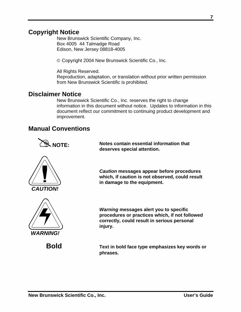
NOTE:
Notes contain essential information that deserves special attention.
CAUTION!
Caution messages appear before procedures which, if caution is not observed, could result in damage to the equipment.
WARNING!
Warning messages alert you to specific procedures or practices which, if not followed correctly, could result in serious personal injury.
Bold Text in bold face type emphasizes key words or
phrases.
New Brunswick Scientific Co., Inc. User’s Guide

8
THIS PAGE IS INTENTIONALLY BLANK
C-24 Classic Benchtop Incubator Shaker User’s Guide

9
Every Instrument manufactured by the New Brunswick Scientific Co., Inc. is warranted to be free
from defects in material and workmanship. This apparatus, with the exception of glassware, lamps and electrodes (where supplied), is warranted against faulty components and assembly for 2 years
in the United States & Canada and for 1 year elsewhere. Our obligation under this warranty is limited to repairing or replacing
the instrument or part thereof, which shall, upon our examination, prove to be defective. The warranty period begins at the date of shipment. This warranty does not extend to any NBS products
which have been subjected to misuse, neglect, accident or improper installation or application; nor shall it extend to products which have been repaired or altered outside the
NBS factory without prior authorization from the New Brunswick Scientific Co., Inc.
W A R R A N T Y
New Brunswick Scientific Co., Inc. User’s Guide

10
THIS PAGE IS INTENTIONALLY BLANK
C-24 Classic Benchtop Incubator Shaker User’s Guide
11
TABLE OF CONTENTS
1 OVERVIEW.......................................................................................................................13
1.1 SPECIFICATIONS............................................................................................................14
2 INSPECTION, VERIFICATION & UNPACKING OF EQUIPMENT.......................15
2.1 INSPECTION OF BOXES ..................................................................................................15 2.2 PACKING LIST VERIFICATION .......................................................................................15 2.3 UNPACKING OF EQUIPMENT..........................................................................................15 2.4 INSPECTION OF EQUIPMENT...........................................................................................16
3 PREPARING THE LOCATION......................................................................................17
3.1 PHYSICAL LOCATION ....................................................................................................17 3.2 ENVIRONMENT..............................................................................................................17
4 C-24 SHAKER FEATURES .............................................................................................19
4.1 KEYPAD ........................................................................................................................19 4.2 PLATFORM ASSEMBLIES ...............................................................................................20
5 GETTING STARTED.......................................................................................................21
5.1 INSTALLATION OF PLATFORM .......................................................................................21 5.2 INSTALLING FLASK CLAMPS .........................................................................................22 5.3 ELECTRICAL CONNECTIONS ..........................................................................................23
6 OPERATION .....................................................................................................................25
6.1 STARTING THE C-24......................................................................................................25 6.2 CONTINUOUS (UNLIMITED) RUN...................................................................................25 6.3 CHECKING ANY SETPOINT ............................................................................................26 6.4 TIMED FUNCTIONS ........................................................................................................26 6.5 ALARM FUNCTIONS.......................................................................................................27 6.6 TEMPERATURE SETPOINT..............................................................................................27 6.7 TOTAL RUNNING TIME..................................................................................................27 6.8 MAINT INDICATOR........................................................................................................27 6.9 POWER FAILURE ...........................................................................................................28
7 PREVENTIVE MAINTENANCE....................................................................................29
7.1 CLEANING EXTERNAL SURFACES..................................................................................29 7.2 FUSE REPLACEMENT.....................................................................................................29 7.3 BELT REPLACEMENT.....................................................................................................30
8 TROUBLESHOOTING ....................................................................................................33
9 REPLACEMENT PARTS AND ACCESSORY INFORMATION ..............................35
9.1 REPLACEMENT PARTS...................................................................................................35 9.2 ACCESSORIES................................................................................................................35
New Brunswick Scientific Co., Inc. User’s Guide
12
9.2.1 Cleaning Supplies ................................................................................................35 9.2.2 Dedicated Platforms ............................................................................................35 9.2.3 Universal Platform ..............................................................................................35 9.2.4 Accessory Flask Clamps ......................................................................................36 9.2.5 Carriers & Test Tube Racks ................................................................................36
10 DRAWINGS ...................................................................................................................39
10.1 LIST OF DRAWINGS .......................................................................................................41 10.2 LIST OF TABLES ............................................................................................................41
11 INDEX.............................................................................................................................43
C-24 Classic Benchtop Incubator Shaker User’s Guide
13
11 OOVVEERRVVIIEEWW
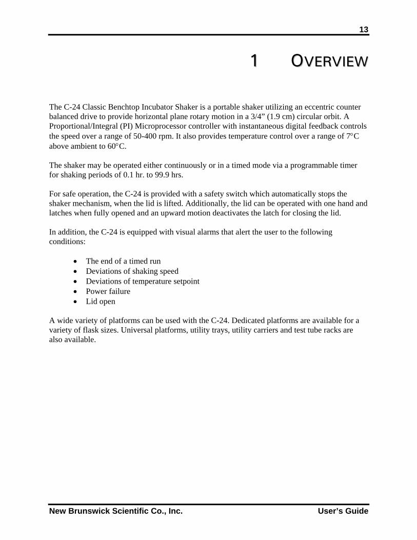
The C-24 Classic Benchtop Incubator Shaker is a portable shaker utilizing an eccentric counter balanced drive to provide horizontal plane rotary motion in a 3/4” (1.9 cm) circular orbit. A Proportional/Integral (PI) Microprocessor controller with instantaneous digital feedback controls the speed over a range of 50-400 rpm. It also provides temperature control over a range of 7°C above ambient to 60°C. The shaker may be operated either continuously or in a timed mode via a programmable timer for shaking periods of 0.1 hr. to 99.9 hrs. For safe operation, the C-24 is provided with a safety switch which automatically stops the shaker mechanism, when the lid is lifted. Additionally, the lid can be operated with one hand and latches when fully opened and an upward motion deactivates the latch for closing the lid. In addition, the C-24 is equipped with visual alarms that alert the user to the following conditions:
• The end of a timed run • Deviations of shaking speed • Deviations of temperature setpoint • Power failure • Lid open
A wide variety of platforms can be used with the C-24. Dedicated platforms are available for a variety of flask sizes. Universal platforms, utility trays, utility carriers and test tube racks are also available.
New Brunswick Scientific Co., Inc. User’s Guide
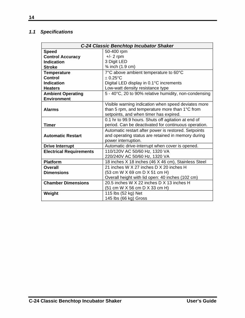
14 1.1 Specifications
C-24 Classic Benchtop Incubator Shaker Speed Control Accuracy Indication Stroke
50-400 rpm +/- 2 rpm 3 Digit LED ¾ inch (1.9 cm)
Temperature Control Indication Heaters
7°C above ambient temperature to 60°C ± 0.25°C Digital LED display in 0.1°C increments Low-watt density resistance type
Ambient Operating Environment
5 - 40°C, 20 to 90% relative humidity, non-condensing
Alarms
Visible warning indication when speed deviates more than 5 rpm, and temperature more than 1°C from setpoints, and when timer has expired.
Timer
0.1 hr to 99.9 hours. Shuts off agitation at end of period. Can be deactivated for continuous operation.
Automatic Restart
Automatic restart after power is restored. Setpoints and operating status are retained in memory during power interruption.
Drive Interrupt Automatic drive-interrupt when cover is opened. Electrical Requirements 110/120V AC 50/60 Hz, 1320 VA
220/240V AC 50/60 Hz, 1320 VA Platform 18 inches X 18 inches (46 X 46 cm), Stainless Steel Overall Dimensions
21 inches W X 27 inches D X 20 inches H (53 cm W X 69 cm D X 51 cm H) Overall height with lid open: 40 inches (102 cm)
Chamber Dimensions 20.5 inches W X 22 inches D X 13 inches H (51 cm W X 56 cm D X 33 cm H)
Weight 115 lbs (52 kg) Net 145 lbs (66 kg) Gross
C-24 Classic Benchtop Incubator Shaker User’s Guide
15
22 IINNSSPPEECCTTIIOONN,, VVEERRIIFFIICCAATTIIOONN && UUNNPPAACCKKIINNGG OOFF EEQQUUIIPPMMEENNTT
2.1 Inspectio After youfor any dcarrier an
2.2 Packing
Verify ag
2.3 Unpackin
Save all pduring shSatisfacti There areRemove
New Brunswic
WARNING! The unit is heavy. Do not attempt to lift or move it by yourself.
n of Boxes
receive your order from New Brunswick Scientific, inspect the boxes carefully amage that may have occurred during shipping. Report any damage to the d to your local NBS Sales Order Department.
List Verification
ainst your NBS packing list that you have received the correct materials.
g of Equipment
acking materials and User’s Guide. If any part of your order was damaged ipping, missing pieces, or fails to operate properly, please fill out the Customer on Form 6300 and return by fax.
two small plastic straps holding the bearing housing in place during shipping. the straps from the bearing housing once the unit is unpacked and inspected.
k Scientific Co., Inc. User’s Guide
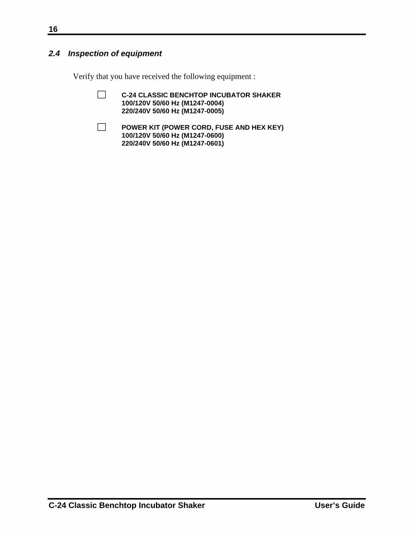
16 2.4 Inspection of equipment
Verify that you have received the following equipment :
C-24 CLASSIC BENCHTOP INCUBATOR SHAKER 100/120V 50/60 Hz (M1247-0004) 220/240V 50/60 Hz (M1247-0005)
POWER KIT (POWER CORD, FUSE AND HEX KEY)
100/120V 50/60 Hz (M1247-0600) 220/240V 50/60 Hz (M1247-0601)
C-24 Classic Benchtop Incubator Shaker User’s Guide
17
33 PPRREEPPAARRIINNGG TTHHEE LLOOCCAATTIIOONN
3.1 Physical
It is essenthe shakewhich theload oper
3.2 Environm
The shak
• •
New Brunswic
WARNING! The unit is heavy. Do not attempt to lift or move it by yourself.
Location
tial that the instrument be situated in a area where there is sufficient space for r and platform to clear walls and obstructions during operation. The surface on unit is placed must be smooth, level, and able to support the shaker under full ating conditions.
ent
er is designed to operate optimally in the following ambient conditions:
5 - 40°C 20 to 90% Relative Humidity non-condensing
k Scientific Co., Inc. User’s Guide

18
THIS PAGE IS INTENTIONALLY BLANK
C-24 Classic Benchtop Incubator Shaker User’s Guide
19
44 CC--2244 SSHHAAKKEERR FFEEAATTUURREESS
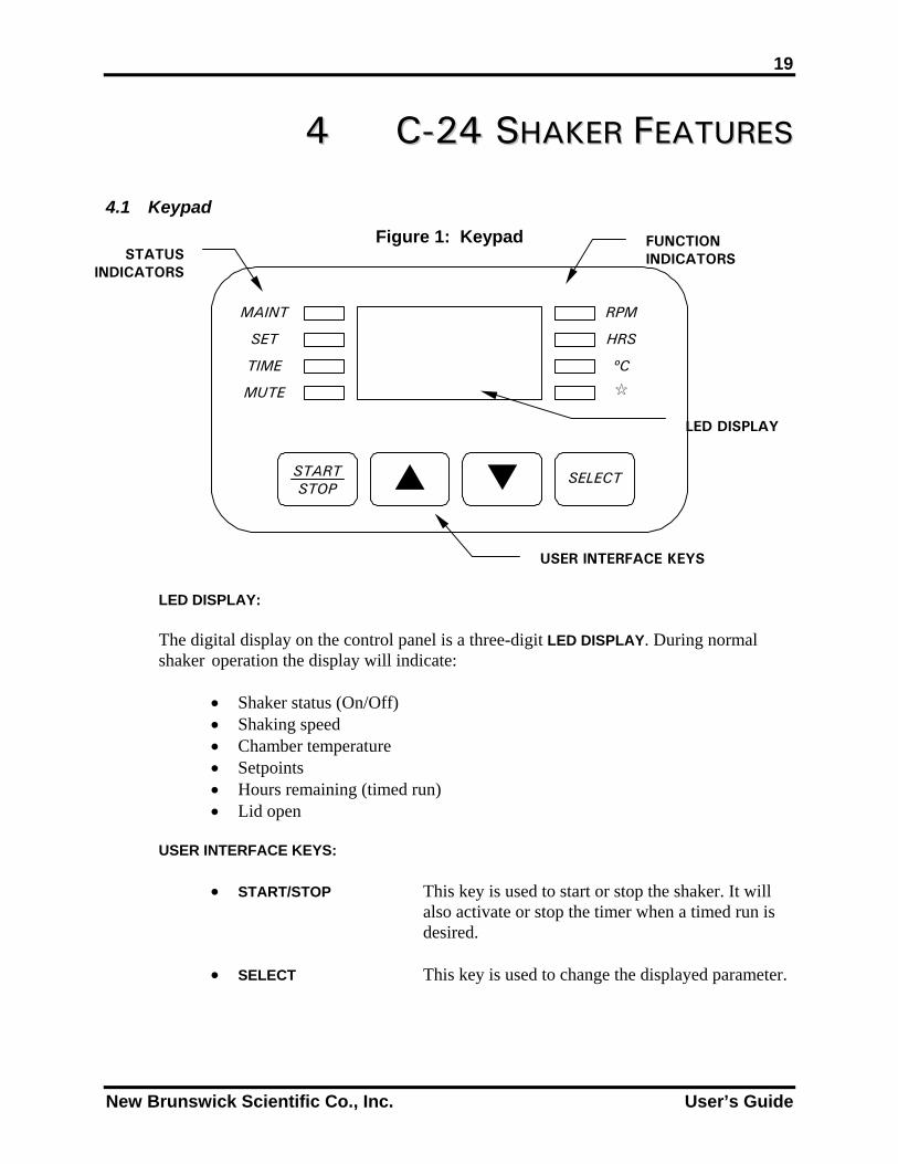
4.1 Keypad Figure 1: Keypad
MAINT
SET
TIME
MUTE
RPM
HRS
ºC
START STOP
SELECT
FUNCTION INDICATORS STATUS
INDICATORS
LED DISPLAY
USER INTERFACE KEYS
LED DISPLAY:
The digital display on the control panel is a three-digit LED DISPLAY. During normal shaker operation the display will indicate:
• Shaker status (On/Off) • Shaking speed • Chamber temperature • Setpoints • Hours remaining (timed run) • Lid open
USER INTERFACE KEYS:
• START/STOP This key is used to start or stop the shaker. It will also activate or stop the timer when a timed run is desired.
• SELECT This key is used to change the displayed parameter.
New Brunswick Scientific Co., Inc. User’s Guide
20
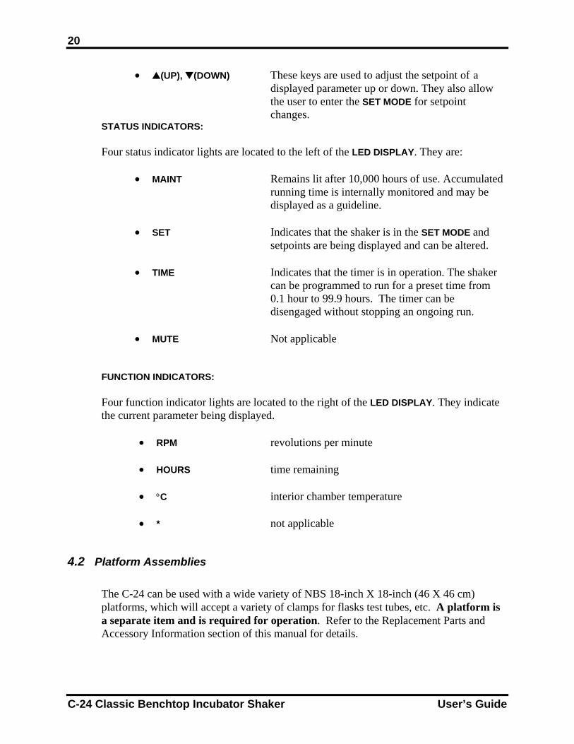
• (UP), (DOWN) These keys are used to adjust the setpoint of a displayed parameter up or down. They also allow the user to enter the SET MODE for setpoint changes.
STATUS INDICATORS: Four status indicator lights are located to the left of the LED DISPLAY. They are:
• MAINT Remains lit after 10,000 hours of use. Accumulated running time is internally monitored and may be displayed as a guideline.
• SET Indicates that the shaker is in the SET MODE and setpoints are being displayed and can be altered. • TIME Indicates that the timer is in operation. The shaker can be programmed to run for a preset time from 0.1 hour to 99.9 hours. The timer can be
disengaged without stopping an ongoing run. • MUTE Not applicable
FUNCTION INDICATORS: Four function indicator lights are located to the right of the LED DISPLAY. They indicate the current parameter being displayed.
• RPM revolutions per minute
• HOURS time remaining
• °C interior chamber temperature
• * not applicable
4.2 Platform Assemblies
The C-24 can be used with a wide variety of NBS 18-inch X 18-inch (46 X 46 cm) platforms, which will accept a variety of clamps for flasks test tubes, etc. A platform is a separate item and is required for operation. Refer to the Replacement Parts and Accessory Information section of this manual for details.
C-24 Classic Benchtop Incubator Shaker User’s Guide
21
55 GGEETTTTIINNGG SSTTAARRTTEEDD
5.1 Installation of Platform
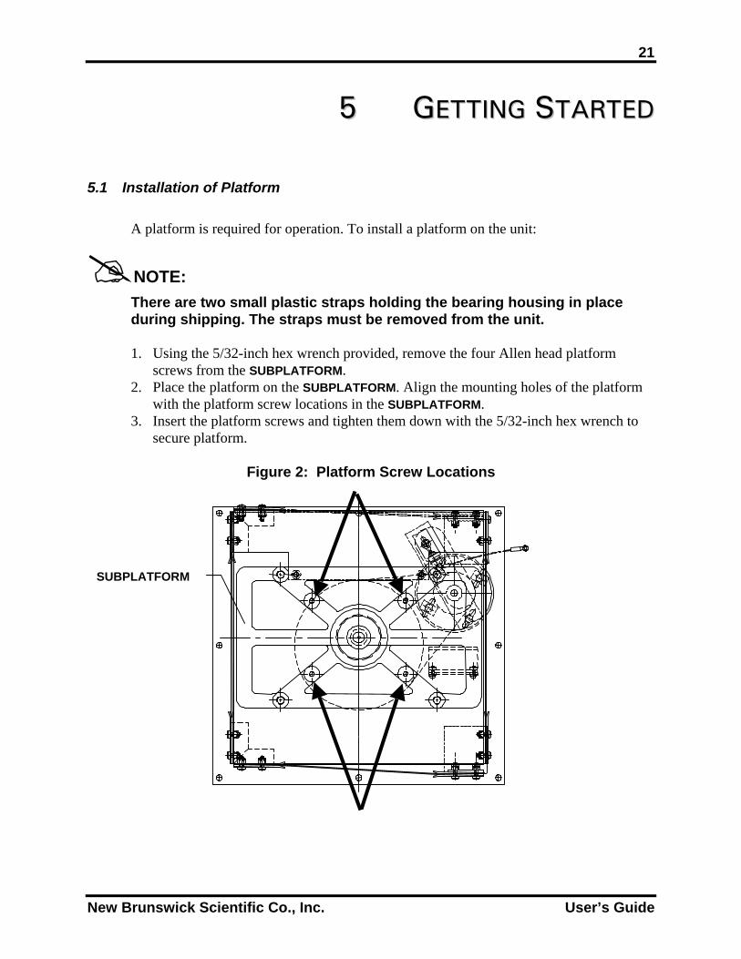
A platform is required for operation. To install a platform on the unit:
NOTE:
There are two small plastic straps holding the bearing housing in place during shipping. The straps must be removed from the unit.
1. Using the 5/32-inch hex wrench provided, remove the four Allen head platform
screws from the SUBPLATFORM. 2. Place the platform on the SUBPLATFORM. Align the mounting holes of the platform
with the platform screw locations in the SUBPLATFORM. 3. Insert the platform screws and tighten them down with the 5/32-inch hex wrench to
secure platform.
Figure 2: Platform Screw Locations
SUBPLATFORM
New Brunswick Scientific Co., Inc. User’s Guide
22 5.2 Installing Flask Clamps
Flask clamps purchased for use with universal platforms (see Section 9.2) require installation. Clamps are installed by securing the base of the clamp to the platform with the correct type and number of screws. All clamps are shipped complete with hardware. Clamps for 2-, 2.8- and 4-liter flasks are shipped with an additional girdle to keep the flasks in place. The girdle is an assembly of springs and sections of rubber tubing. One girdle is already in place on the clamp, the other is packed separately. To install these double girdle clamps:
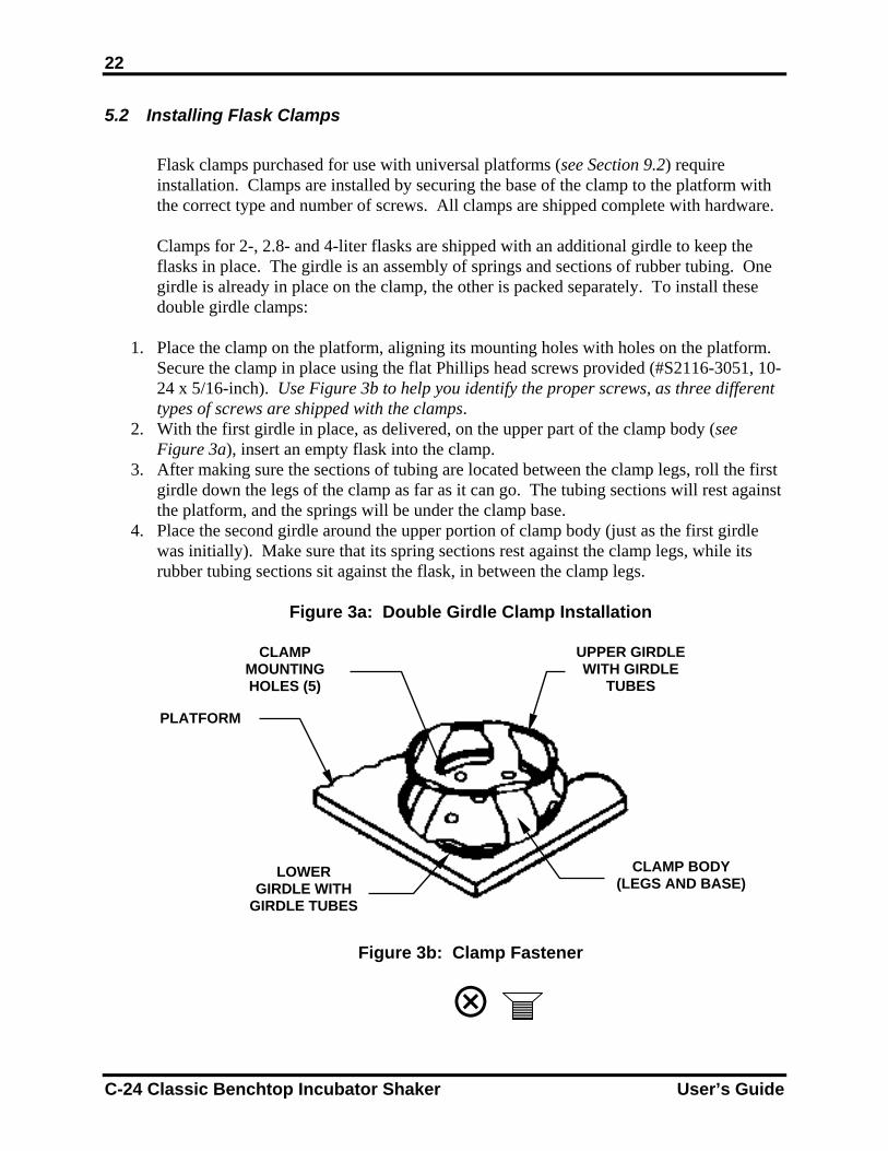
1. Place the clamp on the platform, aligning its mounting holes with holes on the platform.
Secure the clamp in place using the flat Phillips head screws provided (#S2116-3051, 10-24 x 5/16-inch). Use Figure 3b to help you identify the proper screws, as three different types of screws are shipped with the clamps.
2. With the first girdle in place, as delivered, on the upper part of the clamp body (see Figure 3a), insert an empty flask into the clamp.
3. After making sure the sections of tubing are located between the clamp legs, roll the first girdle down the legs of the clamp as far as it can go. The tubing sections will rest against the platform, and the springs will be under the clamp base.
4. Place the second girdle around the upper portion of clamp body (just as the first girdle was initially). Make sure that its spring sections rest against the clamp legs, while its rubber tubing sections sit against the flask, in between the clamp legs.
Figure 3a: Double Girdle Clamp Installation
Figure 3b: Clamp Fastener
UPPER GIRDLE WITH GIRDLE
TUBES
CLAMP MOUNTING HOLES (5)
PLATFORM
CLAMP BODY (LEGS AND BASE)
LOWER GIRDLE WITH
GIRDLE TUBES
C-24 Classic Benchtop Incubator Shaker User’s Guide
23
NOTE:
The upper girdle secures the flask within the clamp, and the bottom girdle keeps the flask from spinning.
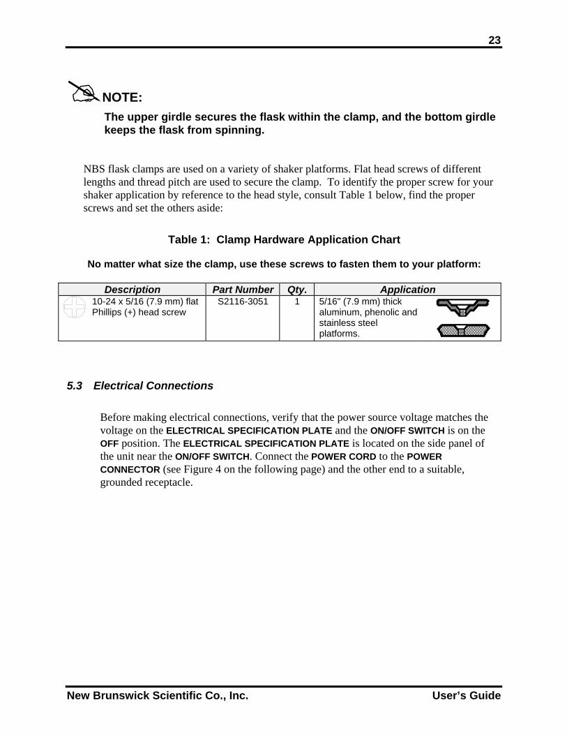
NBS flask clamps are used on a variety of shaker platforms. Flat head screws of different lengths and thread pitch are used to secure the clamp. To identify the proper screw for your shaker application by reference to the head style, consult Table 1 below, find the proper screws and set the others aside:
Table 1: Clamp Hardware Application Chart
No matter what size the clamp, use these screws to fasten them to your platform:
Description Part Number Qty. Application
10-24 x 5/16 (7.9 mm) flat Phillips (+) head screw
S2116-3051 1 5/16" (7.9 mm) thick aluminum, phenolic and stainless steel platforms.
5.3 Electrical Connections
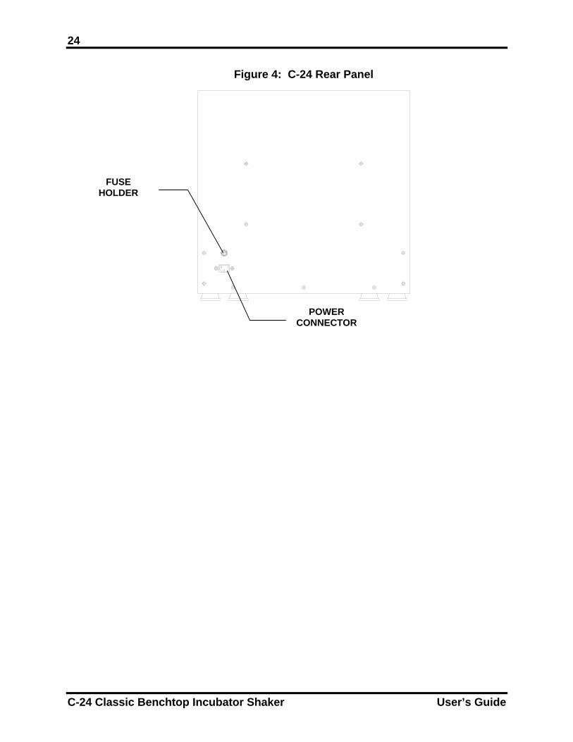
Before making electrical connections, verify that the power source voltage matches the voltage on the ELECTRICAL SPECIFICATION PLATE and the ON/OFF SWITCH is on the OFF position. The ELECTRICAL SPECIFICATION PLATE is located on the side panel of the unit near the ON/OFF SWITCH. Connect the POWER CORD to the POWER CONNECTOR (see Figure 4 on the following page) and the other end to a suitable, grounded receptacle.
New Brunswick Scientific Co., Inc. User’s Guide
24
Figure 4: C-24 Rear Panel
FUSE HOLDER
POWER CONNECTOR
C-24 Classic Benchtop Incubator Shaker User’s Guide
25
66 OOPPEERRAATTIIOONN
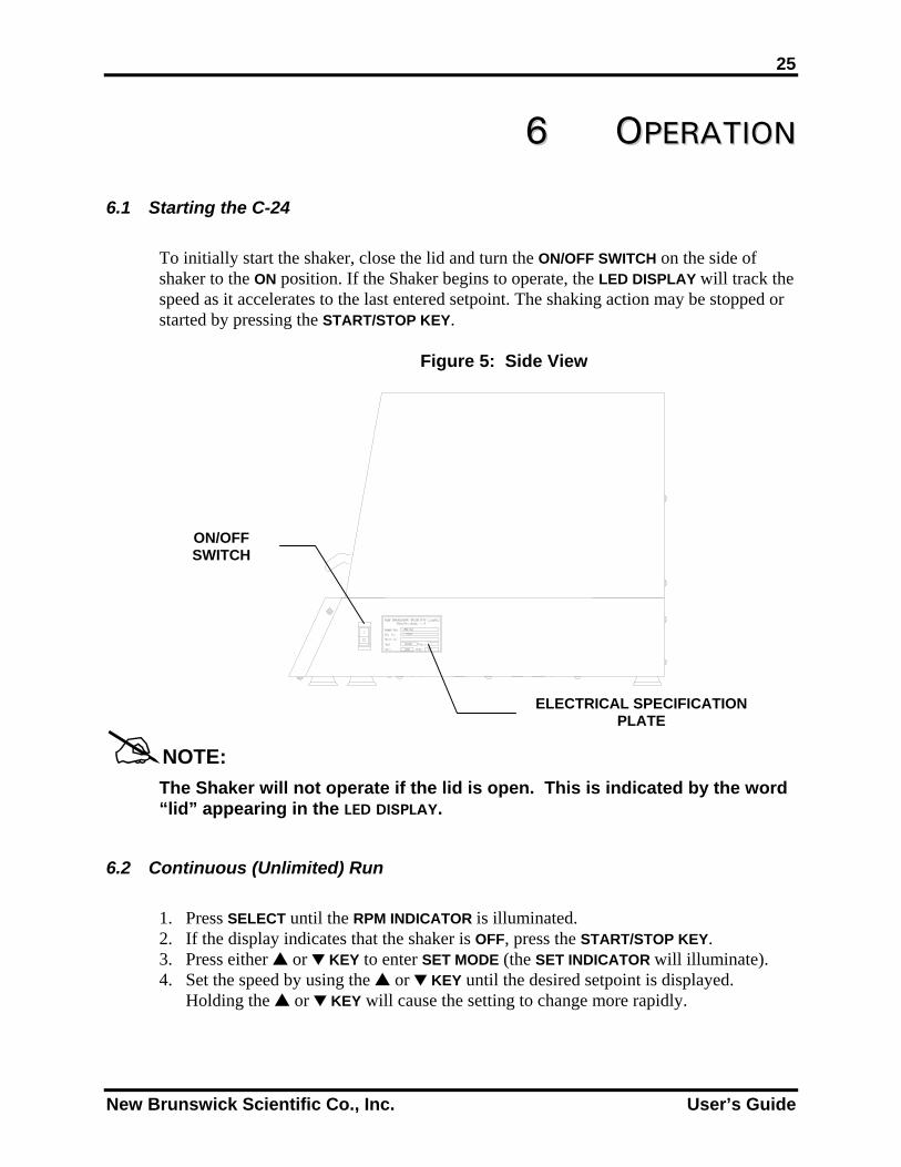
6.1 Starting the C-24
To initially start the shaker, close the lid and turn the ON/OFF SWITCH on the side of shaker to the ON position. If the Shaker begins to operate, the LED DISPLAY will track the speed as it accelerates to the last entered setpoint. The shaking action may be stopped or started by pressing the START/STOP KEY.
Figure 5: Side View
ON/OFF SWITCH
ELECTRICAL SPECIFICATION PLATE
NOTE:
The Shaker will not operate if the lid is open. This is indicated by the word “lid” appearing in the LED DISPLAY.
6.2 Continuous (Unlimited) Run
1. Press SELECT until the RPM INDICATOR is illuminated. 2. If the display indicates that the shaker is OFF, press the START/STOP KEY. 3. Press either or KEY to enter SET MODE (the SET INDICATOR will illuminate). 4. Set the speed by using the or KEY until the desired setpoint is displayed.
Holding the or KEY will cause the setting to change more rapidly.
New Brunswick Scientific Co., Inc. User’s Guide
26
NOTE:
The setpoint may be changed during a run without stopping the shaker by following steps 2-4. During speed changes, a visual alarm (flashing RPM INDICATOR) will flash until the speed returns to within 5 rpm of the setpoint.
6.3 Checking Any Setpoint
1. Press SELECT until the desired indicator is illuminated. 2. Press either or KEY to enter the SET MODE and display the current setpoint.
6.4 Timed Fu
The shak0.1 hour However
To set th 1. Press2. Press3. While
time duratTIME
To disabany other
To cance
Repeat stINDICATO
C-24 Classic B
CAUTION! Holding the or for more than 0.5 seconds causes the speed setpoint to change. Should this occur, resetting will benecessary.
nctions
er may be programmed to automatically stop after a preset time period of - 99.9 hours. There must be power to the shaker in order to set the timer. , a timed run can be initiated while the unit is either shaking or stopped.
e timer:
the SELECT KEY until the HRS INDICATOR is illuminated. either or KEY to enter the SET MODE and set between 0.1 - 99.9 hours. the SET INDICATOR is illuminated, press the START/STOP KEY to program the
(and start the run). The TIME INDICATOR will light and remain on for the ion of the run. At the end of the timed run the display will read OFF, and the INDICATOR will flash.
le the alarm (flashing TIME INDICATOR), press the SELECT KEY and change to function.
l the timer without stopping the shaker:
eps 1 and 2. Then immediately press the START/STOP KEY. The TIME R will cease to flash and the display will read OFF.
enchtop Incubator Shaker User’s Guide
27 6.5 Alarm Functions
The shaker has a visible alarm (flashing TIME INDICATOR) that is activated (a) at the end of a timed run, or (b) if the temperature is 1ºC or more from the setpoint, or if the speed is 5 RPM or more from the setpoint.
6.6 Temperature Setpoint
Press the SELECT KEY until the function °C INDICATOR illuminates. The temperature can be set from 7°C above the current ambient temperature up to 60.0°C. Ambient temperature is defined as the temperature within one meter of the shaker. Increase or decrease the setpoint using the or KEY. During operation, if the temperature of the chamber is more than 1.0°C higher or lower than the temperature setpoint, a visual alarm is triggered. This alarm consists of a flashing °C INDICATOR. The alarm will automatically deactivate as the unit achieves the set temperature.
6.7 Total Running Time
The control modules of the C-24 shaker totalize the time the shaker has been “ON” to track hours of usage. To display the accumulated running time:
1. Press SELECT until the HRS INDICATOR is illuminated. 2. Simultaneously press the and KEYS.
The SET and MAINT INDICATORS will flash and the accumulated running time will be displayed in hundreds of hours (i.e., “02” equals 200 hours; “102” equals 10,200 hours). This display will continue for 10 seconds and then default to the previous mode readout.
6.8 Maint Indicator After 10,000 hours of operation, the MAINT INDICATOR will illuminate. Preventive maintenance is recommended at this point. To deactivate the MAINT INDICATOR: 1. Press SELECT until the HRS INDICATOR is illuminated. 2. Simultaneously press the and KEYS. 3. Press the KEY.
New Brunswick Scientific Co., Inc. User’s Guide
28 6.9 Power Failure
In the event of a power failure, the C-24 Benchtop Incubator Shaker is equipped with an automatic restart function. If the Shaker was in operation prior to the power interruption, the Shaker will begin to operate at its last entered setpoint. The LED DISPLAY will flash indicating that a power failure has occurred. Press any key to cease the flashing in the display.
C-24 Classic Benchtop Incubator Shaker User’s Guide
29
77 PPRREEVVEENNTTIIVVEE MMAAIINNTTEENNAANNCCEE
WARNING! Always turn off the shaker and disconnect the power cord from the power supply before performing maintenance on the unit.
7.1 Cleaning External Surfaces
The unit may be cleaned using a damp cloth or any standard, household or laboratory cleaner to wipe down its outer surfaces. Do not use abrasive or corrosive compounds to clean this instrument, as they may damage the unit and void the warranty. The exercise of reasonable care in cleaning the chamber lid will minimize scratching. Wash the plastic cover with a mild soap or detergent and lukewarm water solution. Rinse well. Dry by blotting with a damp cloth or chamois. Polish the cover with NBS door/lid polish and polishing cloths (P0860-0949). Do NOT use: window cleaning fluids, scouring compounds, gritty cloths, leaded or ethylene gasolines or solvents such as alcohol, acetone, carbon tetrachloride, etc.
7.2 Fuse Replacement
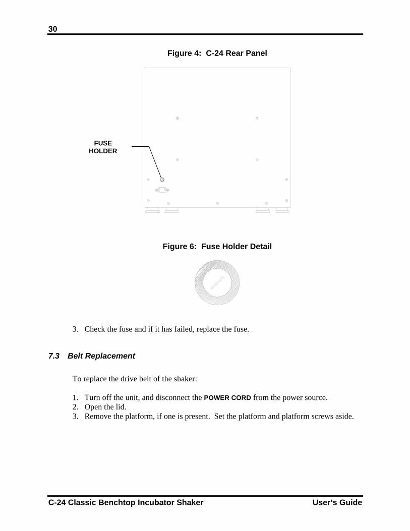
The electrical fuse of the unit is housed in the fuse holder on the rear panel of the unit above the POWER CORD CONNECTOR. To check or replace the fuse:
1. Set the ON/OFF SWITCH to OFF and disconnect the POWER CORD from the power
source.
2. Insert a small flat-bladed screwdriver into the fuse holder groove (see Figure 4, repeated for reference on the following page & Figure 6 below it) and turn counter-clockwise until it disengages and the fuse holder springs free.
New Brunswick Scientific Co., Inc. User’s Guide
30
Figure 4: C-24 Rear Panel
Figure 6: Fuse Holder Detail
FUSE HOLDER
3. Check the fuse and if it has failed, replace the fuse.
7.3 Belt Replacement
To replace the drive belt of the shaker:
1. Turn off the unit, and disconnect the POWER CORD from the power source. 2. Open the lid. 3. Remove the platform, if one is present. Set the platform and platform screws aside.
C-24 Classic Benchtop Incubator Shaker User’s Guide
31
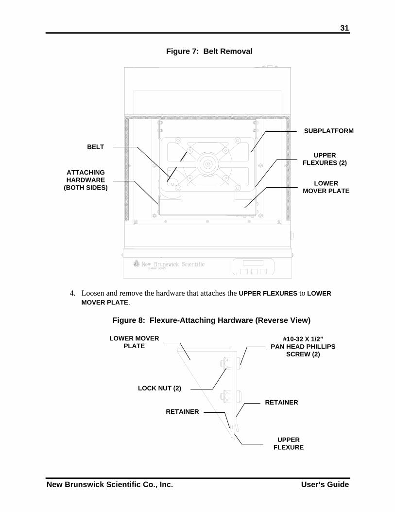
Figure 7: Belt Removal
SUBPLATFORM
BELT UPPER
FLEXURES (2)ATTACHING HARDWARE
(BOTH SIDES) LOWER MOVER PLATE
4. Loosen and remove the hardware that attaches the UPPER FLEXURES to LOWER MOVER PLATE.
Figure 8: Flexure-Attaching Hardware (Reverse View)
LOWER MOVERPLATE
#10-32 X 1/2” PAN HEAD PHILLIPS
SCREW (2)
LOCK NUT (2)
RETAINER RETAINER
UPPER FLEXURE
New Brunswick Scientific Co., Inc. User’s Guide
32
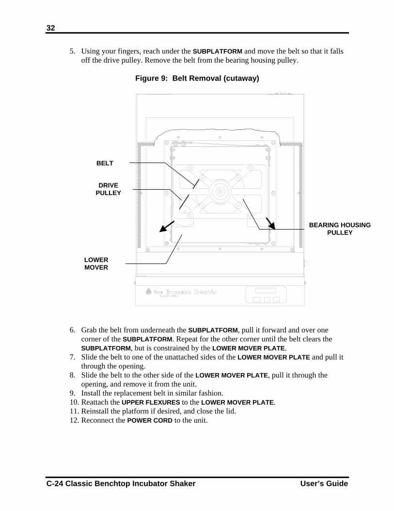
5. Using your fingers, reach under the SUBPLATFORM and move the belt so that it falls off the drive pulley. Remove the belt from the bearing housing pulley.
Figure 9: Belt Removal (cutaway)
BELT
DRIVE PULLEY
BEARING HOUSING PULLEY
LOWER MOVER
6. Grab the belt from underneath the SUBPLATFORM, pull it forward and over one corner of the SUBPLATFORM. Repeat for the other corner until the belt clears the SUBPLATFORM, but is constrained by the LOWER MOVER PLATE.
7. Slide the belt to one of the unattached sides of the LOWER MOVER PLATE and pull it through the opening.
8. Slide the belt to the other side of the LOWER MOVER PLATE, pull it through the opening, and remove it from the unit.
9. Install the replacement belt in similar fashion. 10. Reattach the UPPER FLEXURES to the LOWER MOVER PLATE. 11. Reinstall the platform if desired, and close the lid. 12. Reconnect the POWER CORD to the unit.
C-24 Classic Benchtop Incubator Shaker User’s Guide
33
88 TTRROOUUBBLLEESSHHOOOOTTIINNGG If any problems occur with your shaker, do not attempt to perform any service on the unit other than specified in this manual. Unauthorized servicing may void the warranty. Please contact your local NBS Sales Order Department In any correspondence with NBS, please refer to the Model Number and Serial Number of your unit. This information is on the ELECTRICAL SPECIFICATION PLATE which is located on the side panel of the unit near the ON/OFF SWITCH.
New Brunswick Scientific Co., Inc. User’s Guide

34
THIS PAGE IS INTENTIONALLY BLANK
C-24 Classic Benchtop Incubator Shaker User’s Guide
35
99 RREEPPLLAACCEEMMEENNTT PPAARRTTSS AANNDD
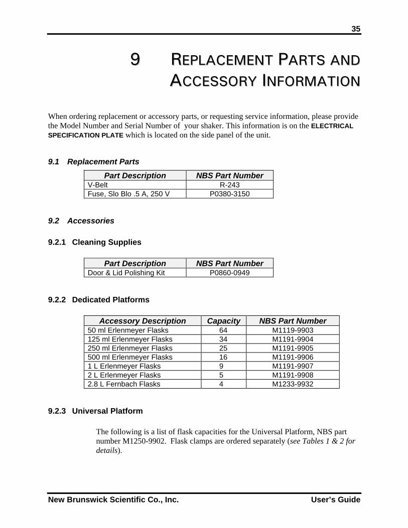
AACCCCEESSSSOORRYY IINNFFOORRMMAATTIIOONN When ordering replacement or accessory parts, or requesting service information, please provide the Model Number and Serial Number of your shaker. This information is on the ELECTRICAL SPECIFICATION PLATE which is located on the side panel of the unit.
9.1 Replacement Parts Part Description NBS Part Number
V-Belt R-243 Fuse, Slo Blo .5 A, 250 V P0380-3150
9.2 Accessories
9.2.1 Cleaning Supplies
Part Description NBS Part Number Door & Lid Polishing Kit P0860-0949
9.2.2 Dedicated Platforms Accessory Description Capacity NBS Part Number
50 ml Erlenmeyer Flasks 64 M1119-9903 125 ml Erlenmeyer Flasks 34 M1191-9904 250 ml Erlenmeyer Flasks 25 M1191-9905 500 ml Erlenmeyer Flasks 16 M1191-9906 1 L Erlenmeyer Flasks 9 M1191-9907 2 L Erlenmeyer Flasks 5 M1191-9908 2.8 L Fernbach Flasks 4 M1233-9932
9.2.3 Universal Platform The following is a list of flask capacities for the Universal Platform, NBS part number M1250-9902. Flask clamps are ordered separately (see Tables 1 & 2 for details).
New Brunswick Scientific Co., Inc. User’s Guide
36
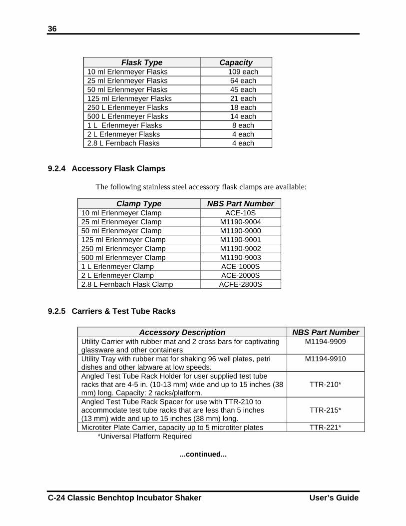
Flask Type Capacity
10 ml Erlenmeyer Flasks 109 each 25 ml Erlenmeyer Flasks 64 each 50 ml Erlenmeyer Flasks 45 each 125 ml Erlenmeyer Flasks 21 each 250 L Erlenmeyer Flasks 18 each 500 L Erlenmeyer Flasks 14 each 1 L Erlenmeyer Flasks 8 each 2 L Erlenmeyer Flasks 4 each 2.8 L Fernbach Flasks 4 each
9.2.4 Accessory Flask Clamps
The following stainless steel accessory flask clamps are available:
Clamp Type NBS Part Number 10 ml Erlenmeyer Clamp ACE-10S 25 ml Erlenmeyer Clamp M1190-9004 50 ml Erlenmeyer Clamp M1190-9000 125 ml Erlenmeyer Clamp M1190-9001 250 ml Erlenmeyer Clamp M1190-9002 500 ml Erlenmeyer Clamp M1190-9003 1 L Erlenmeyer Clamp ACE-1000S 2 L Erlenmeyer Clamp ACE-2000S 2.8 L Fernbach Flask Clamp ACFE-2800S
9.2.5 Carriers & Test Tube Racks
Accessory Description NBS Part Number Utility Carrier with rubber mat and 2 cross bars for captivating glassware and other containers
M1194-9909
Utility Tray with rubber mat for shaking 96 well plates, petri dishes and other labware at low speeds.
M1194-9910
Angled Test Tube Rack Holder for user supplied test tube racks that are 4-5 in. (10-13 mm) wide and up to 15 inches (38 mm) long. Capacity: 2 racks/platform.
TTR-210*
Angled Test Tube Rack Spacer for use with TTR-210 to accommodate test tube racks that are less than 5 inches (13 mm) wide and up to 15 inches (38 mm) long.
TTR-215*
Microtiter Plate Carrier, capacity up to 5 microtiter plates TTR-221* *Universal Platform Required
...continued...
C-24 Classic Benchtop Incubator Shaker User’s Guide
37
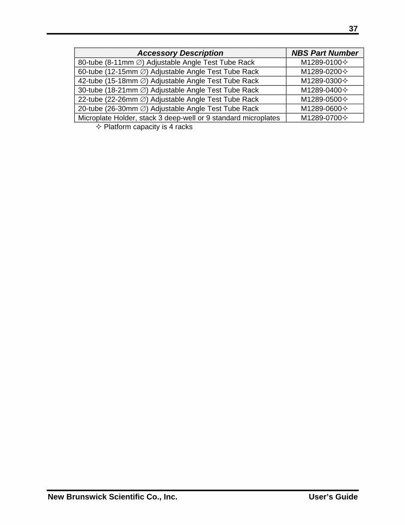
Accessory Description NBS Part Number 80-tube (8-11mm ∅) Adjustable Angle Test Tube Rack M1289-0100 60-tube (12-15mm ∅) Adjustable Angle Test Tube Rack M1289-0200 42-tube (15-18mm ∅) Adjustable Angle Test Tube Rack M1289-0300 30-tube (18-21mm ∅) Adjustable Angle Test Tube Rack M1289-0400 22-tube (22-26mm ∅) Adjustable Angle Test Tube Rack M1289-0500 20-tube (26-30mm ∅) Adjustable Angle Test Tube Rack M1289-0600 Microplate Holder, stack 3 deep-well or 9 standard microplates M1289-0700
Platform capacity is 4 racks
New Brunswick Scientific Co., Inc. User’s Guide

38
THIS PAGE IS INTENTIONALLY BLANK
C-24 Classic Benchtop Incubator Shaker User’s Guide
39
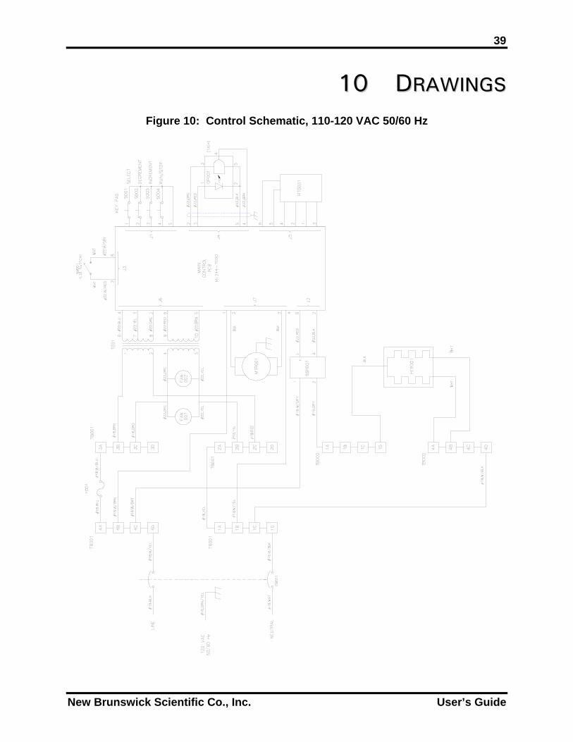
1100 DDRRAAWWIINNGGSS Figure 10: Control Schematic, 110-120 VAC 50/60 Hz
New Brunswick Scientific Co., Inc. User’s Guide

40
Figure 11: Control Schematic, 220-240 VAC 50/60 Hz
C-24 Classic Benchtop Incubator Shaker User’s Guide
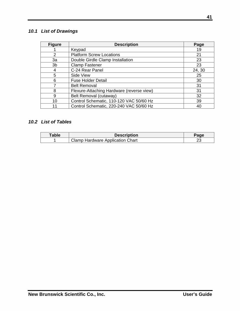
41 10.1 List of Drawings
Figure Description Page 1 Keypad 19 2 Platform Screw Locations 21
3a Double Girdle Clamp Installation 23 3b Clamp Fastener 23 4 C-24 Rear Panel 24, 30 5 Side View 25 6 Fuse Holder Detail 30 7 Belt Removal 31 8 Flexure-Attaching Hardware (reverse view) 31 9 Belt Removal (cutaway) 32
10 Control Schematic, 110-120 VAC 50/60 Hz 39 11 Control Schematic, 220-240 VAC 50/60 Hz 40
10.2 List of Tables
Table Description Page 1 Clamp Hardware Application Chart 23
New Brunswick Scientific Co., Inc. User’s Guide

42
THIS PAGE IS INTENTIONALLY BLANK
C-24 Classic Benchtop Incubator Shaker User’s Guide
43
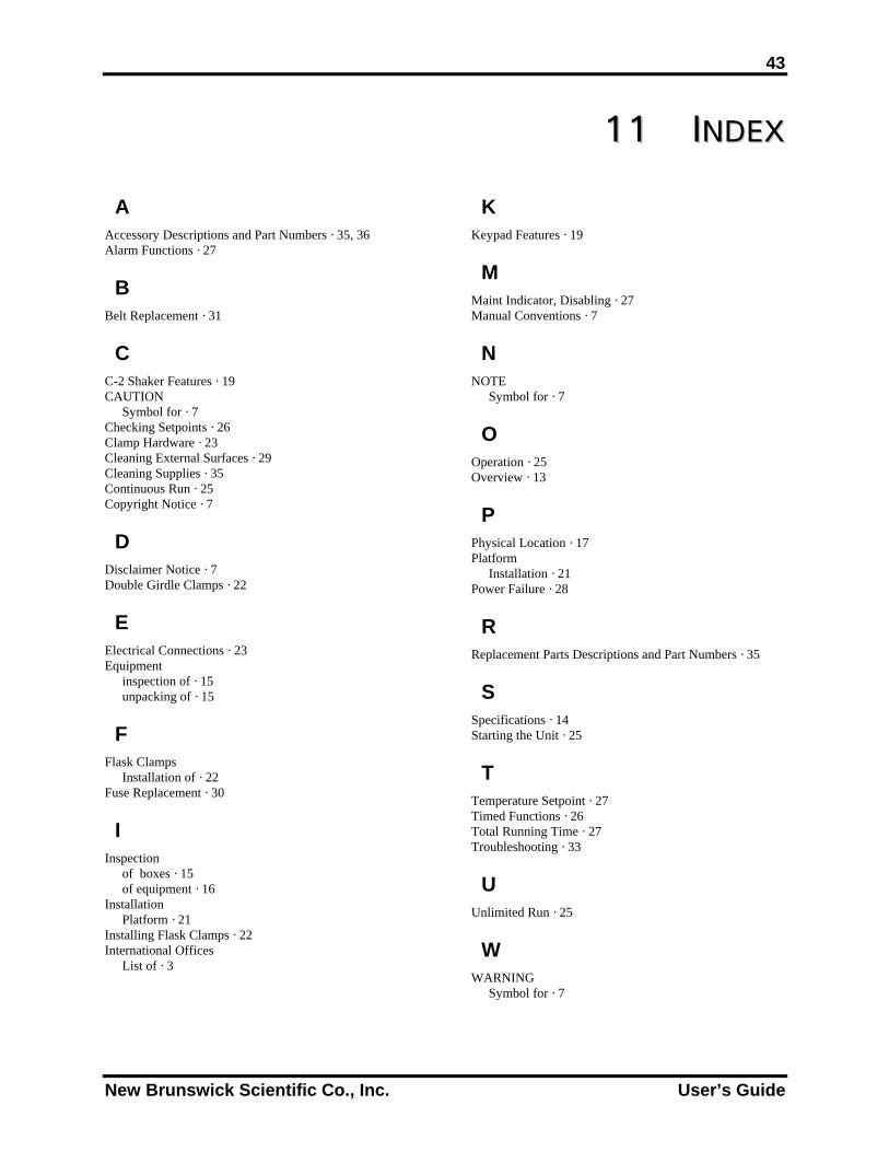
1111 IINNDDEEXX
A Accessory Descriptions and Part Numbers · 35, 36 Alarm Functions · 27
B Belt Replacement · 31
C C-2 Shaker Features · 19 CAUTION
Symbol for · 7 Checking Setpoints · 26 Clamp Hardware · 23 Cleaning External Surfaces · 29 Cleaning Supplies · 35 Continuous Run · 25 Copyright Notice · 7
D Disclaimer Notice · 7 Double Girdle Clamps · 22
E Electrical Connections · 23 Equipment
inspection of · 15 unpacking of · 15
F Flask Clamps
Installation of · 22 Fuse Replacement · 30
I Inspection
of boxes · 15 of equipment · 16
Installation Platform · 21
Installing Flask Clamps · 22 International Offices
List of · 3
K Keypad Features · 19
M Maint Indicator, Disabling · 27 Manual Conventions · 7
N NOTE
Symbol for · 7
O Operation · 25 Overview · 13
P Physical Location · 17 Platform
Installation · 21 Power Failure · 28
R Replacement Parts Descriptions and Part Numbers · 35
S Specifications · 14 Starting the Unit · 25
T Temperature Setpoint · 27 Timed Functions · 26 Total Running Time · 27 Troubleshooting · 33
U Unlimited Run · 25
W WARNING
Symbol for · 7
New Brunswick Scientific Co., Inc. User’s Guide