
C 091 A/B/D Series - Amphenol Sine Systemsamphenol-sine.com/pdf/catalog/C091.pdf · Amphenol...
72
Amphenol Amphenol-Tuchel Electronics GmbH C 091 A/B/D Series Circular Connectors www.industrial-amphenol.com
Transcript of C 091 A/B/D Series - Amphenol Sine Systemsamphenol-sine.com/pdf/catalog/C091.pdf · Amphenol...

AmphenolAmphenol-Tuchel Electronics GmbH
C 091 A/B/D SeriesCircular Connectors
www.industrial-amphenol.com

2
Note from the CEO
Ladies and Gentlemen,
For over 75 years Amphenol has enjoyed success as the interconnection technologyprovider of choice to industry-leading companies around the world. One of our key stra-tegic areas of focus has been and is the Industrial market. Our organization works withleading manufacturers across a wide range of applications - including Energy Generation& Distribution, Transportation, Heavy Equipment, Factory Automation, Wireless Outdoor,ChipCard Readers - enabling smarter, faster and better technologies to connect pro-ducts to customer solutions.
The Industrial market footprint of Amphenol covers over facilities in more than 12different European countries and more than 30 countries worldwide. Our successfulexpansion into new regions as well as new industrial applications is a direct reflection ofour agile, entrepreneurial management team and our unwavering commitment to execu-te Amphenol‘s strategies for the benefit of our customers, shareholders and employees.
Thank you for partnering with Amphenol. Our entire organization is at your service.
R. Adam NorwittPresident and CEO, Amphenol Corporation

3
C 091
Make use of the bestUse our global resources
“Think global, act local!” Independently from where you are in Europe, we offeryou our global expertise and great variety of products and technologies. And incomfort with your personal contact. Our numerous European offices are youraccess to our global resources.
OUR OFFICES IN EUROPE AND WORLDWIDE
FRANCE CHINA AUSTRALIA SOUTH AFRICAGERMANY KOREA MEXICO INDIAUNITED KINGDOM TAIWAN USA ITALY

4
C 091
SECURITY, RELIABILITY AND COMFORTABLE SERVICE FROM ONE SOURCE.

5
More time for important things:benefit from our service and diversityEnjoy security, reliability and comfortable service from one source.INDUSTRIAL@AMPHENOL offers one of the most individual and most diversified serviceprogrammes in the market – exclusively for industrial customers. Access all possibilities ofthe Amphenol group through your personal expert adviser.
WIDE PRODUCT RANGE
Take advantage of a choice of Amphenol products. Our broadproduct portfolio offers individual solutions from more than 90member companies in the global Amphenol group.
QUALITY
Interconnect systems need reliability, speed and flawless datatransmission. We continuously test and guarantee the requiredstandard in our products – and also in our personal services.
SPEED AND AVAILABILITY
Smart and intelligent processes are the secret behind our serviceprogramme. Flexible planning and distribution, perfect logistics and highest availability are our key factors for best customer service.
EXCLUSIVENESS AND FLEXIBILITY
One face to the customer: every inquiry is handled on an individualservice level by your personal key account service partner. Thisensures maximum transparency and best-in-class flexibility in thewhole process.
INDIVIDUAL SOLUTIONS
Your project requires an individual solution that is not available off-the-shelf? As your think tank and discussion partner we provideengineering support and solution-oriented development for yourtailor-made Amphenol product.
GLOBAL KEY ACCOUNT SERVICE
Our key account service is your individual entrance to globalknow-how, products and services. More than 90 Amphenolcompanies around the world offer an extensive range oftechnologies and products. We offer access to our worldwideresources through one individual contact person.

6
7
C 091 Content
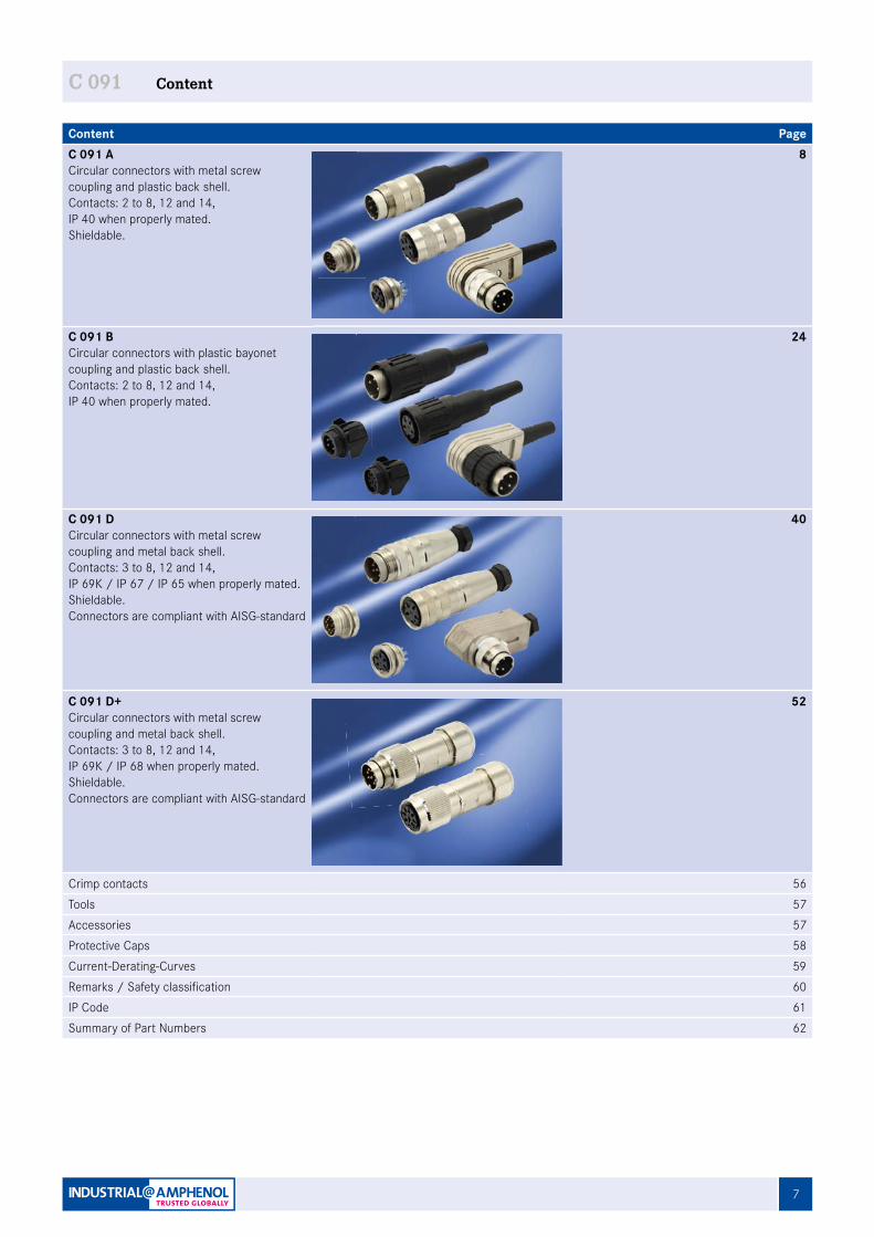
Content PageC 091 ACircular connectors with metal screw coupling and plastic back shell. Contacts: 2 to 8, 12 and 14, IP 40 when properly mated.Shieldable.
8
C 091 BCircular connectors with plastic bayonet coupling and plastic back shell. Contacts: 2 to 8, 12 and 14, IP 40 when properly mated.
24
C 091 DCircular connectors with metal screw coupling and metal back shell. Contacts: 3 to 8, 12 and 14, IP 69K / IP 67 / IP 65 when properly mated.Shieldable.Connectors are compliant with AISG-standard
40
C 091 D+Circular connectors with metal screw coupling and metal back shell. Contacts: 3 to 8, 12 and 14, IP 69K / IP 68 when properly mated.Shieldable.Connectors are compliant with AISG-standard
52
Crimp contacts 56Tools 57Accessories 57Protective Caps 58Current-Derating-Curves 59Remarks / Safety classification 60IP Code 61Summary of Part Numbers 62
C 091
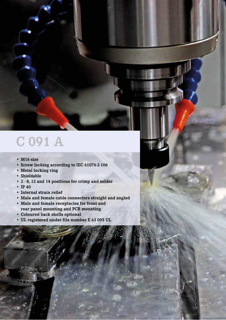
• M16 size• Screw locking according to IEC 61076-2-106• Metal locking ring• Shieldable• 2 - 8, 12 and 14 positions for crimp and solder • IP 40• Internal strain relief• Male and female cable connectors straight and angled• Male and female receptacles for front and rear panel mounting and PCB mounting • Coloured back shells optional• UL registered under file number E 63 093 UL
C 091 A
9
C 091 A Characteristics
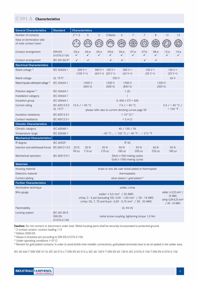
General Characteristics Standard CharacteristicsNumber of contacts 2 1)+ 3 4 5 5 Stereo 6 7 7 8 12 14View on termination sideof male contact insert
Contact arrangement DIN EN 61076-2-106
03-aü
04-aü
05-aü
05-bü
06-aü
07-aü
07-bü
08-aü
12-aü
14-aü
Contact arrangement IEC 60130-92) ü ü ü ü ü ü
Electrical CharacteristicsRated voltage 3) IEC 60664-1 300 V ≃
(100 V ≃)300 V ≃(63 V ≃)
100 V ≃(32 V ≃)
300 V ≃(63 V ≃)
100 V ≃(32 V ≃)
150 V ≃(32 V ≃)
Rated voltage UL 1977 250 V 60 VRated impulse withstand voltage 3) IEC 60664-1 1500 V
(840 V)1200 V(500 V)
1500 V(840 V)
1200 V(500 V)
Pollution degree 3) IEC 60664-1 1 (2)Installation category IEC 60664-1 IInsulation group IEC 60664-1 II, 400 ≤ CTI < 600Current rating IEC 60512-5-2
UL 197710 A / + 40 °C 7 A / + 40 °C 3 A / + 40 °C /
+ 104 °Fplease refer also to current derating curves page 59Insulation resistance IEC 60512-3-1 > 1010 Ω 4)
Contact resistance IEC 60512-2-1 < 5 m ΩClimatic CharacteristicsClimatic category IEC 60068-1 40 / 100 / 56Temperature range IEC 60068-1 - 40 °C ... + 100 °C / - 40 °F ... + 212 °FMechanical CharacteristicsIP-degree IEC 60529 IP 40Insertion and withdrawal forces IEC 60512-13-2 25 N
90.oz30 N
110.oz35 N
125.oz50 N
180.oz55 N
200.oz60 N
220.oz50 N
180.ozMechanical operation IEC 60512-9-1 Silver ≥ 500 mating cycles
Gold ≥ 1000 mating cyclesMaterialsHousing material brass or zinc die cast nickel plated or thermoplastDielectric material thermoplasticContact plating silver plated / gold plated 5)
Further CharacteristicsTermination technique solder, crimpWire gauge solder: ≤ 0,5 mm2 / 20 AWG
crimp: 2 - 6 pol (excluding 5S): 0,09 - 1,00 mm2 / 28 - 18 AWGcrimp: 5S, 7, 7S and 8-pol.: 0,09 - 0,75 mm2 / 28 - 20 AWG
solder: ≤ 0,25 mm² / 24 AWG
crimp: 0,09-0,25 mm² / 28 – 24 AWG
Flammability UL 94 V0Locking system IEC 60130-9
DIN EN 61076-2-106
metal screw coupling; tightening torque 1,0 Nm
Caution: Do not connect or disconnect under load. Metal housing parts shall be securely incorporated to protected ground.1) 2 contact version: contact loading 1+32) Edition 2000-053) Values in brackets are according to DIN EN 61076-2-1064) Under operating conditions >108 Ω5) Remark for gold plated contacts: In order to avoid brittle inter-metallic connections, gold-plated terminals have to be tin-plated in the solder area.
IEC 60 664 = DIN VDE 0110; IEC 60 512-x = DIN EN 60 512-x; IEC 60 130-9 = DIN EN 60 130-9; IEC 61076-2-106 = DIN EN 61076-2-106
2
2 + 3
31 1
2 3
4
4
4
5
32
1
5 5 Stereo
5
3
4
1
2 4
5
32
16
6
16 7 2
5 34
7
37
21
6
54
7
8
2
8
5
3
4
176
L CD
B
NA
OEF
MK
JH
G
14
L CD
BAEF
MK
JH
G
12
101) See remark page 9 2) Contact arrangement acc. to DIN EN 61076-2-106 "0X-b"
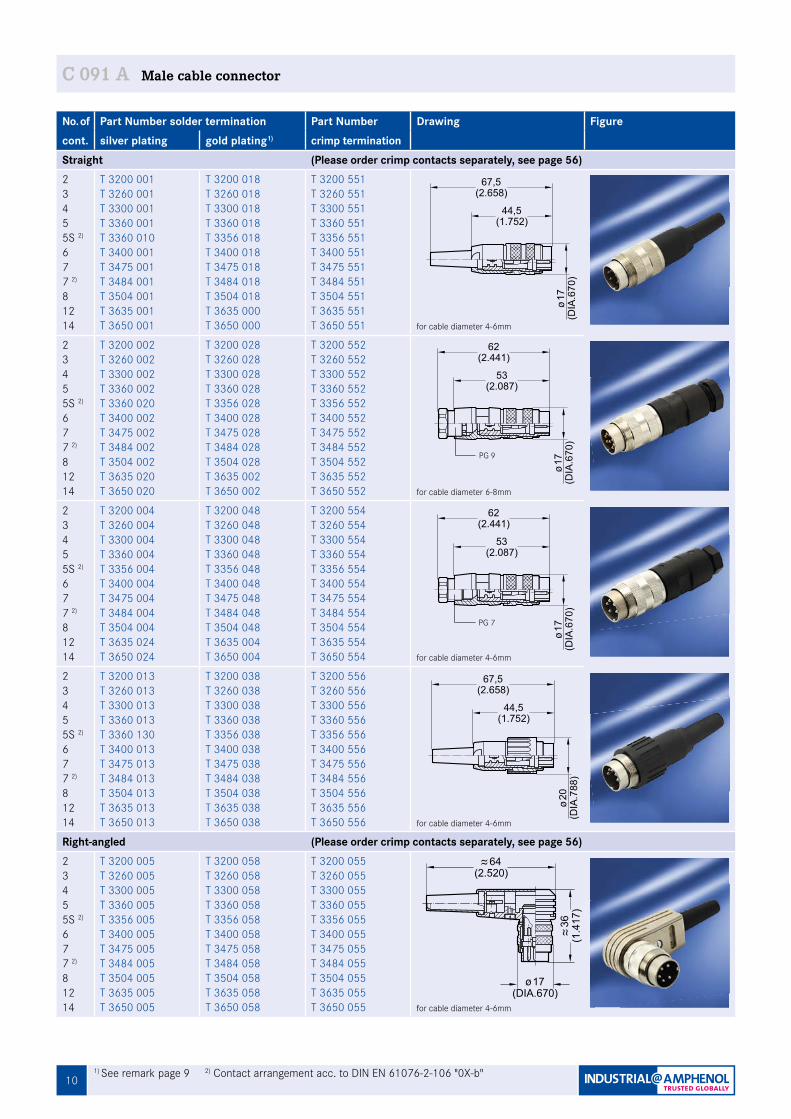
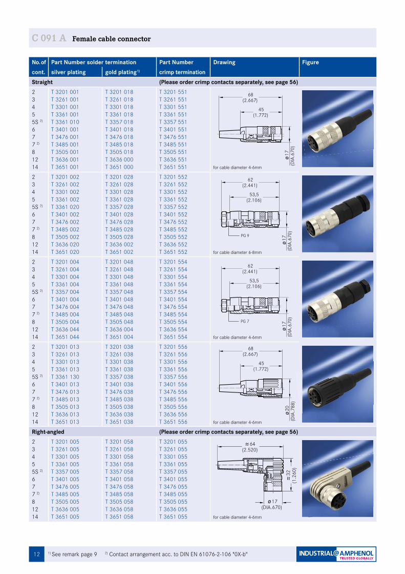
C 091 A Male cable connector
No. of Part Number solder termination Part Number Drawing Figurecont. silver plating gold plating1) crimp termination Straight (Please order crimp contacts separately, see page 56)2345 5S 2)
677 2)
81214
T 3200 001T 3260 001T 3300 001T 3360 001T 3360 010T 3400 001T 3475 001T 3484 001T 3504 001T 3635 001T 3650 001
T 3200 018T 3260 018T 3300 018T 3360 018T 3356 018 T 3400 018T 3475 018T 3484 018 T 3504 018T 3635 000T 3650 000
T 3200 551T 3260 551T 3300 551T 3360 551T 3356 551T 3400 551T 3475 551T 3484 551T 3504 551T 3635 551 T 3650 551 for cable diameter 4-6mm
2345 5S 2)
677 2)
81214
T 3200 002T 3260 002T 3300 002T 3360 002T 3360 020T 3400 002T 3475 002T 3484 002T 3504 002T 3635 020T 3650 020
T 3200 028T 3260 028T 3300 028T 3360 028T 3356 028 T 3400 028T 3475 028T 3484 028 T 3504 028T 3635 002T 3650 002
T 3200 552T 3260 552T 3300 552T 3360 552T 3356 552 T 3400 552T 3475 552T 3484 552T 3504 552 T 3635 552 T 3650 552 for cable diameter 6-8mm
2345 5S 2)
677 2)
81214
T 3200 004T 3260 004T 3300 004T 3360 004T 3356 004 T 3400 004T 3475 004T 3484 004 T 3504 004T 3635 024T 3650 024
T 3200 048 T 3260 048 T 3300 048 T 3360 048T 3356 048 T 3400 048 T 3475 048 T 3484 048 T 3504 048 T 3635 004T 3650 004
T 3200 554T 3260 554 T 3300 554 T 3360 554 T 3356 554T 3400 554 T 3475 554 T 3484 554 T 3504 554T 3635 554 T 3650 554 for cable diameter 4-6mm
2345 5S 2)
677 2)
81214
T 3200 013 T 3260 013T 3300 013T 3360 013T 3360 130T 3400 013T 3475 013 T 3484 013 T 3504 013T 3635 013T 3650 013
T 3200 038T 3260 038T 3300 038T 3360 038T 3356 038T 3400 038T 3475 038T 3484 038T 3504 038T 3635 038T 3650 038
T 3200 556T 3260 556T 3300 556T 3360 556T 3356 556T 3400 556T 3475 556T 3484 556T 3504 556T 3635 556T 3650 556 for cable diameter 4-6mm
Right-angled (Please order crimp contacts separately, see page 56)2345 5S 2)
677 2)
81214
T 3200 005T 3260 005T 3300 005T 3360 005T 3356 005T 3400 005T 3475 005T 3484 005T 3504 005T 3635 005T 3650 005
T 3200 058T 3260 058 T 3300 058 T 3360 058T 3356 058 T 3400 058T 3475 058 T 3484 058 T 3504 058 T 3635 058T 3650 058
T 3200 055T 3260 055T 3300 055 T 3360 055T 3356 055 T 3400 055 T 3475 055 T 3484 055 T 3504 055T 3635 055 T 3650 055 for cable diameter 4-6mm
17(D
IA.6
70)
44,5(1.752)
(2.658)67,5
Fig. C 091A-1a
53(2.087)
62(2.441)
17(D
IA.6
70)
Fig. C 091A-2a
53(2.087)
62(2.441)
17(D
IA.6
70)
Fig. C 091A-3a
44,5(1.752)
67,5(2.658)
20(D
IA.7
88)
Fig. C 091A-4a
(DIA.670)17
36(1
.417
)
64(2.520)
Fig. C 091A-45a
PG 7
PG 9
111) For further information see page 60 2) Solder version only
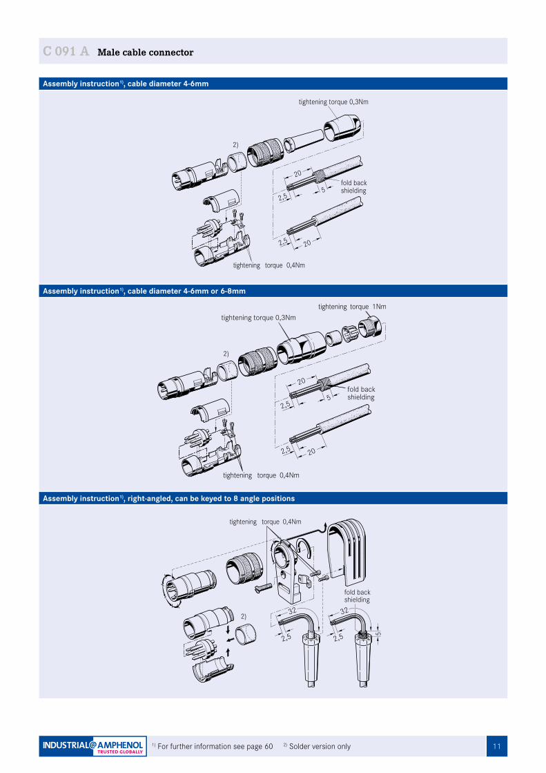
C 091 A Male cable connector
Assembly instruction1), cable diameter 4-6mm
Assembly instruction1), cable diameter 4-6mm or 6-8mm
Assembly instruction1), right-angled, can be keyed to 8 angle positions
2,5
20
2,5 20
5
tightening torque 0,3Nm
tightening torque 0,4Nm
fold backshielding
2,5 20
2,5
20
5
tightening torque 0,4Nm
tightening torque 1Nmtightening torque 0,3Nm
fold backshielding
2)
2)
2,5
32
2,5
32
5
fold backshielding
tightening torque 0,4Nm
2)
12 1) See remark page 9 2) Contact arrangement acc. to DIN EN 61076-2-106 "0X-b"
C 091 A Female cable connector
No. of Part Number solder termination Part Number Drawing Figurecont. silver plating gold plating1) crimp termination Straight (Please order crimp contacts separately, see page 56)2345 5S 2)
677 2)
81214
T 3201 001T 3261 001T 3301 001T 3361 001T 3361 010T 3401 001T 3476 001T 3485 001T 3505 001T 3636 001T 3651 001
T 3201 018 T 3261 018T 3301 018 T 3361 018T 3357 018 T 3401 018T 3476 018T 3485 018 T 3505 018T 3636 000T 3651 000
T 3201 551T 3261 551T 3301 551T 3361 551T 3357 551T 3401 551T 3476 551T 3485 551T 3505 551T 3636 551 T 3651 551 for cable diameter 4-6mm
2345 5S 2)
677 2)
81214
T 3201 002T 3261 002T 3301 002T 3361 002T 3361 020T 3401 002T 3476 002T 3485 002T 3505 002T 3636 020T 3651 020
T 3201 028T 3261 028T 3301 028 T 3361 028T 3357 028 T 3401 028T 3476 028 T 3485 028 T 3505 028T 3636 002T 3651 002
T 3201 552T 3261 552 T 3301 552 T 3361 552T 3357 552 T 3401 552 T 3476 552T 3485 552 T 3505 552 T 3636 552 T 3651 552 for cable diameter 6-8mm
2345 5S 2)
677 2)
81214
T 3201 004T 3261 004 T 3301 004T 3361 004T 3357 004 T 3401 004T 3476 004 T 3485 004 T 3505 004T 3636 044T 3651 044
T 3201 048T 3261 048T 3301 048T 3361 048T 3357 048 T 3401 048 T 3476 048 T 3485 048 T 3505 048 T 3636 004 T 3651 004
T 3201 554T 3261 554 T 3301 554T 3361 554 T 3357 554T 3401 554 T 3476 554 T 3485 554 T 3505 554T 3636 554 T 3651 554 for cable diameter 4-6mm
2345 5S 2)
677 2)
81214
T 3201 013 T 3261 013T 3301 013 T 3361 013T 3361 130T 3401 013 T 3476 013T 3485 013 T 3505 013 T 3636 013T 3651 013
T 3201 038T 3261 038T 3301 038T 3361 038T 3357 038T 3401 038T 3476 038T 3485 038T 3505 038T 3636 038T 3651 038
T 3201 556T 3261 556T 3301 556T 3361 556T 3357 556T 3401 556T 3476 556T 3485 556T 3505 556T 3636 556T 3651 556 for cable diameter 4-6mm
Right-angled (Please order crimp contacts separately, see page 56)2345 5S 2)
677 2)
81214
T 3201 005 T 3261 005T 3301 005T 3361 005T 3357 005T 3401 005T 3476 005T 3485 005T 3505 005T 3636 005T 3651 005
T 3201 058T 3261 058 T 3301 058 T 3361 058 T 3357 058 T 3401 058T 3476 058 T 3485 058 T 3505 058 T 3636 058T 3651 058
T 3201 055T 3261 055 T 3301 055 T 3361 055T 3357 055 T 3401 055T 3476 055 T 3485 055T 3505 055T 3636 055 T 3651 055 for cable diameter 4-6mm
45(1.772)
68(2.667)
17(D
IA.6
70)
Fig. C 091A-5a
53,5(2.106)
62(2.441)
17(D
IA.6
70)
Fig. C 091A-6a
53,5(2.106)
62(2.441)
17(D
IA.6
70)
Fig. C 091A-7a
45(1.772)
68(2.667)
20(D
IA.7
88)
Fig. C 091A-8a
PG 7
PG 9
(DIA.670)17
32(1
.260
)
64(2.520)
Fig. C 091A-44a
131) For further information see page 60 2) Solder version only
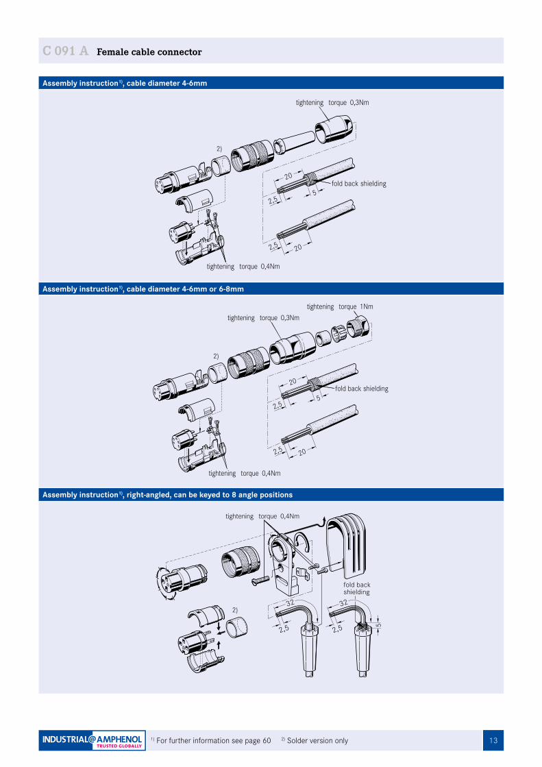
C 091 A Female cable connector
Assembly instruction1), cable diameter 4-6mm
Assembly instruction1), cable diameter 4-6mm or 6-8mm
Assembly instruction1), right-angled, can be keyed to 8 angle positions
2,5 20
tightening torque 0,3Nm
tightening torque 0,4Nm
2,5
20
5fold back shielding
2,5 20
tightening torque 1Nmtightening torque 0,3Nm
tightening torque 0,4Nm
2,5
20
5fold back shielding
2,5
32
2,5
32
5
fold backshielding
tightening torque 0,4Nm
2)
2)
2)
14
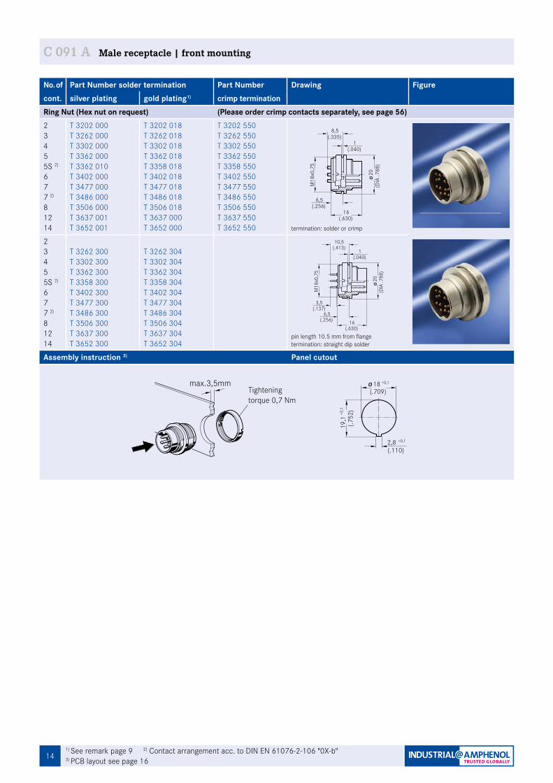
No. of Part Number solder termination Part Number Drawing Figurecont. silver plating gold plating1) crimp termination Ring Nut (Hex nut on request) (Please order crimp contacts separately, see page 56)2345 5S 2)
677 2)
81214
T 3202 000T 3262 000T 3302 000T 3362 000T 3362 010T 3402 000T 3477 000T 3486 000T 3506 000T 3637 001T 3652 001
T 3202 018T 3262 018T 3302 018T 3362 018T 3358 018 T 3402 018T 3477 018T 3486 018 T 3506 018 T 3637 000T 3652 000
T 3202 550T 3262 550 T 3302 550 T 3362 550 T 3358 550 T 3402 550T 3477 550T 3486 550 T 3506 550 T 3637 550 T 3652 550 termination: solder or crimp
2345 5S 2)
677 2)
81214
T 3262 300 T 3302 300 T 3362 300 T 3358 300 T 3402 300 T 3477 300 T 3486 300 T 3506 300 T 3637 300T 3652 300
T 3262 304T 3302 304T 3362 304T 3358 304T 3402 304T 3477 304T 3486 304T 3506 304T 3637 304 T 3652 304
pin length 10.5 mm from flangetermination: straight dip solder
Assembly instruction 3) Panel cutout
max.3,5mm
Fig. C 091A-112a
C 091 A Male receptacle | front mounting
18 +0,1
19,1
(.709)
Fig. C 091A-99a
2,8(.110)
+0,1
(.752
)+0
,1
Tightening torque 0,7 Nm
1) See remark page 9 2) Contact arrangement acc. to DIN EN 61076-2-106 "0X-b" 3) PCB layout see page 16
6,5
16(.630)
8,5(.335)
Fig. C 091A-74a
1(.040)
(.256)
(DIA
.788
)20
M18
x0,7
56,5
(.256)
10,5
M18
x0,7
5
3,5
1(.040)
(.413)
Fig. C 091A-75a
(.137)
(DIA
.788
)20
16(.630)
151) See remark page 9 2) Contact arrangement acc. to DIN EN 61076-2-106 "0X-b" 3) PCB layout see page 16
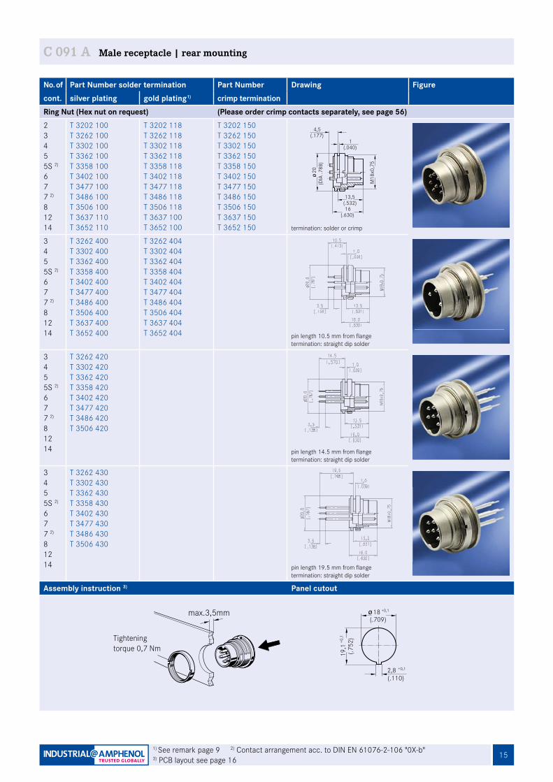
No. of Part Number solder termination Part Number Drawing Figurecont. silver plating gold plating1) crimp termination Ring Nut (Hex nut on request) (Please order crimp contacts separately, see page 56)2345 5S 2)
677 2)
81214
T 3202 100T 3262 100T 3302 100T 3362 100T 3358 100T 3402 100T 3477 100T 3486 100T 3506 100T 3637 110T 3652 110
T 3202 118T 3262 118T 3302 118T 3362 118T 3358 118T 3402 118T 3477 118T 3486 118T 3506 118T 3637 100T 3652 100
T 3202 150T 3262 150 T 3302 150T 3362 150 T 3358 150 T 3402 150 T 3477 150 T 3486 150 T 3506 150 T 3637 150 T 3652 150 termination: solder or crimp
345 5S 2)
677 2)
81214
T 3262 400T 3302 400T 3362 400T 3358 400 T 3402 400T 3477 400T 3486 400 T 3506 400T 3637 400T 3652 400
T 3262 404T 3302 404T 3362 404T 3358 404T 3402 404T 3477 404T 3486 404T 3506 404T 3637 404T 3652 404 pin length 10.5 mm from flange
termination: straight dip solder
345 5S 2)
677 2)
81214
T 3262 420 T 3302 420 T 3362 420 T 3358 420 T 3402 420T 3477 420 T 3486 420 T 3506 420
pin length 14.5 mm from flangetermination: straight dip solder
345 5S 2)
677 2)
81214
T 3262 430 T 3302 430 T 3362 430T 3358 430 T 3402 430 T 3477 430 T 3486 430 T 3506 430
pin length 19.5 mm from flangetermination: straight dip solder
Assembly instruction 3) Panel cutout
max.3,5mm
Fig. C 091A-113a
C 091 A Male receptacle | rear mounting
18 +0,1
19,1
(.709)
Fig. C 091A-99a
2,8(.110)
+0,1
(.752
)+0
,1Tightening torque 0,7 Nm
4,5
13,5
16(.630)
(.532)
(.177)
Fig. C 091A-76a
M18
x0,7
5
1(.040)
(DIA
.788
)20
16
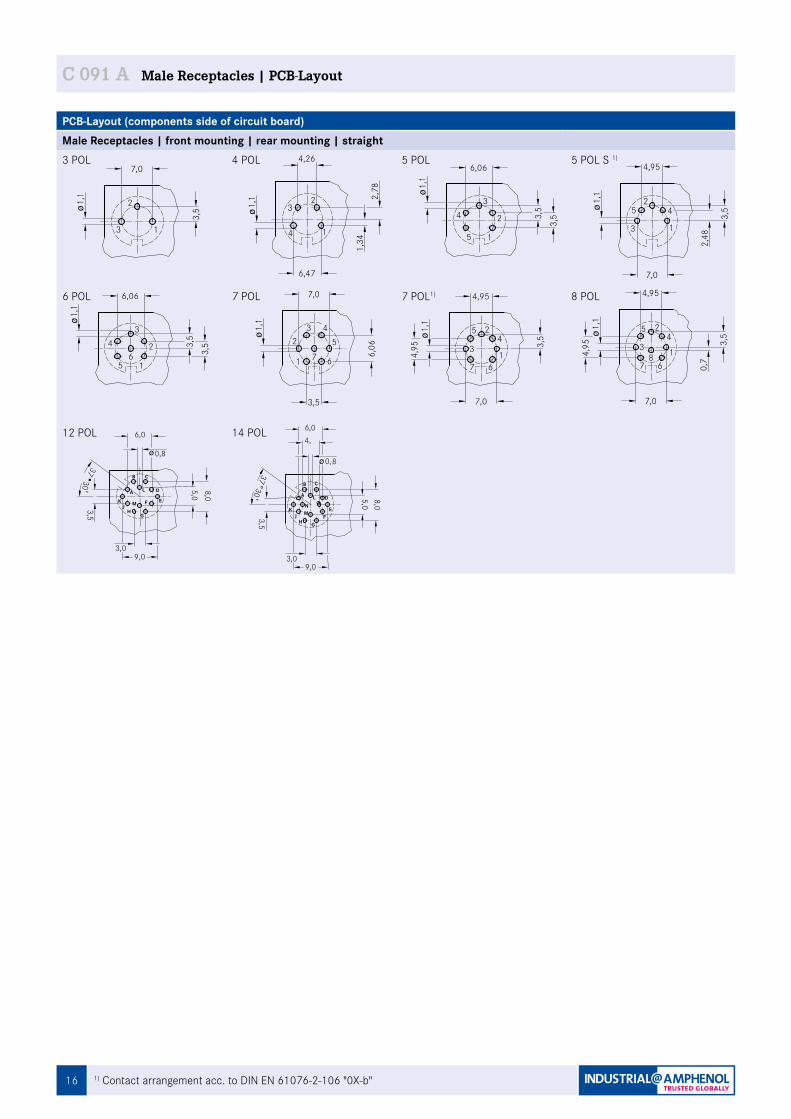
C 091 A Male Receptacles | PCB-Layout
1) Contact arrangement acc. to DIN EN 61076-2-106 "0X-b"
PCB-Layout (components side of circuit board)Male Receptacles | front mounting | rear mounting | straight3 POL 4 POL 5 POL 5 POL S 1)
6 POL 7 POL 7 POL1) 8 POL
12 POL 14 POL
1
1
4,26
6,47
6,06
3,5
7,0
4,95
5
6,06
3,5
3,5
0,7
3,5
3,5
3,53,
53,
53,
5
4,95
4
3
2
13
2
4
33
2
15
4
42
1
53
2
15
46
3 45
61
2
7
5 2
167
3
24
67
38
F
HJ M
K EA
L D
B C
G
HJ M F
K N OE
A L D
B C
G37
30
4,5
5 Pol. Stereo
4 Pol.
12 Pol.
DIN 45 3226 Pol.
DIN 45 3225 Pol.
DIN 41 5243 Pol.
DIN 45 3297 Pol.
DIN 41 5247 Pol.
DIN 45 3268 Pol.
9,03,0
0,8
6,0
5,0
8,0
3,5
14 Pol.
1,1
1,1
1,1
1,1
2,48
1,1
1,1
4,95
1,34
2,78 1,
11,
1
3,09,0
5,0
8,0
3,5
3730
0,8
6,0
4,95
7,0
7,04,95
7,0
6,067,0
1
1
4,26
6,47
6,06
3,5
7,0
4,95
56,
063,
53,
5
0,7
3,5
3,5
3,53,
53,
53,
5
4,95
4
3
2
13
2
4
33
2
15
4
42
1
53
2
15
46
3 45
61
2
7
5 2
167
3
24
67
38
F
HJ M
K EA
L D
B C
G
HJ M F
K N OE
A L D
B C
G
3730
4,5
5 Pol. Stereo
4 Pol.
12 Pol.
DIN 45 3226 Pol.
DIN 45 3225 Pol.
DIN 41 5243 Pol.
DIN 45 3297 Pol.
DIN 41 5247 Pol.
DIN 45 3268 Pol.
9,03,0
0,8
6,0
5,0
8,0
3,5
14 Pol.
1,1
1,1
1,1
1,1
2,48
1,1
1,1
4,95
1,34
2,78
1,1
1,1
3,09,0
5,0
8,0
3,5
3730
0,8
6,0
4,95
7,0
7,04,95
7,0
6,067,0
1
1
4,26
6,47
6,06
3,5
7,0
4,95
56,
063,
53,
5
0,7
3,5
3,5
3,53,
53,
53,
5
4,95
4
3
2
13
2
4
33
2
15
4
42
1
53
2
15
46
3 45
61
2
7
5 2
167
3
24
67
38
F
HJ M
K EA
L D
B C
G
HJ M F
K N OE
A L D
B C
G
3730
4,5
5 Pol. Stereo
4 Pol.
12 Pol.
DIN 45 3226 Pol.
DIN 45 3225 Pol.
DIN 41 5243 Pol.
DIN 45 3297 Pol.
DIN 41 5247 Pol.
DIN 45 3268 Pol.
9,03,0
0,8
6,0
5,0
8,0
3,5
14 Pol.
1,1
1,1
1,1
1,1
2,48
1,1
1,1
4,95
1,34
2,78 1,
11,
1
3,09,0
5,0
8,0
3,5
3730
0,8
6,0
4,95
7,0
7,04,95
7,0
6,067,0
1
1
4,26
6,47
6,06
3,5
7,0
4,95
5
6,06
3,5
3,5
0,7
3,5
3,5
3,53,
53,
53,
5
4,95
4
3
2
13
2
4
33
2
15
4
42
1
53
2
15
46
3 45
61
2
7
5 2
167
3
24
67
38
F
HJ M
K EA
L D
B C
G
HJ M F
K N OE
A L D
B C
G
3730
4,5
5 Pol. Stereo
4 Pol.
12 Pol.
DIN 45 3226 Pol.
DIN 45 3225 Pol.
DIN 41 5243 Pol.
DIN 45 3297 Pol.
DIN 41 5247 Pol.
DIN 45 3268 Pol.
9,03,0
0,8
6,0
5,0
8,0
3,5
14 Pol.
1,1
1,1
1,1
1,1
2,48
1,1
1,1
4,95
1,34
2,78
1,1
1,1
3,09,0
5,0
8,0
3,5
3730
0,8
6,0
4,95
7,0
7,04,95
7,0
6,067,0
1
1
4,26
6,47
6,06
3,5
7,0
4,95
5
6,06
3,5
3,5
0,7
3,5
3,5
3,53,
53,
53,
5
4,95
4
3
2
13
2
4
33
2
15
4
42
1
53
2
15
46
3 45
61
2
7
5 2
167
3
24
67
38
F
HJ M
K EA
L D
B C
G
HJ M F
K N OE
A L D
B C
G
3730
4,5
5 Pol. Stereo
4 Pol.
12 Pol.
DIN 45 3226 Pol.
DIN 45 3225 Pol.
DIN 41 5243 Pol.
DIN 45 3297 Pol.
DIN 41 5247 Pol.
DIN 45 3268 Pol.
9,03,0
0,8
6,0
5,0
8,0
3,5
14 Pol.
1,1
1,1
1,1
1,1
2,48
1,1
1,1
4,95
1,34
2,78 1,
11,
1
3,09,0
5,0
8,0
3,5
3730
0,8
6,0
4,95
7,0
7,04,95
7,0
6,067,0
1
1
4,26
6,47
6,06
3,5
7,0
4,95
5
6,06
3,5
3,5
0,7
3,5
3,5
3,53,
53,
53,
5
4,95
4
3
2
13
2
4
33
2
15
4
42
1
53
2
15
46
3 45
61
2
7
5 2
167
3
24
67
38
F
HJ M
K EA
L D
B C
G
HJ M F
K N OE
A L D
B C
G
3730
4,5
5 Pol. Stereo
4 Pol.
12 Pol.
DIN 45 3226 Pol.
DIN 45 3225 Pol.
DIN 41 5243 Pol.
DIN 45 3297 Pol.
DIN 41 5247 Pol.
DIN 45 3268 Pol.
9,03,0
0,8
6,0
5,0
8,0
3,5
14 Pol.
1,1
1,1
1,1
1,1
2,48
1,1
1,1
4,95
1,34
2,78
1,1
1,1
3,09,0
5,0
8,0
3,5
3730
0,8
6,0
4,95
7,0
7,04,95
7,0
6,067,0
3
4
4,26
6,47
6,06
3,5
7,0
4,95
4
6,06
3,5
3,5
0,7
3,5
3,5
3,53,
53,
53,
5
4,95
5
1
2
31
3
1
23
4
51
2
52
3
43
4
51
26
4 32
16
5
7
4 2
376
1
25
76
18
Fig. C 091A-78a
5 Pol. Stereo
4 Pol.
12 Pol.
DIN 45 3226 Pol.
DIN 45 3225 Pol.
DIN 41 5243 Pol.
DIN 45 3297 Pol.
DIN 41 5247 Pol.
DIN 45 3268 Pol.
14 Pol.
1,1
1,1
1,1
1,1
2,48
1,1
1,1
4,95
1,34
2,78 1,
11,
1
4,95
7,0
7,04,95
7,0
6,067,0
contact arrangement acc. to IEC 60 130-9
5,08,0
3730
3,5
3,09,0
6,0
0,8
B C
A L
KJ H
M
G
FE
D
3730
4,6,0
5,0
9,03,0
3,5
0,8
8,0
BC
LA
KJ H
G
MN
FE
DO
3
4
4,26
6,47
6,06
3,5
7,0
4,95
4
6,06
3,5
3,5
0,7
3,5
3,5
3,53,
53,
53,
5
4,95
5
1
2
31
3
1
23
4
51
2
52
3
43
4
51
26
4 32
16
5
7
4 2
376
1
25
76
18
Fig. C 091A-78a
5 Pol. Stereo
4 Pol.
12 Pol.
DIN 45 3226 Pol.
DIN 45 3225 Pol.
DIN 41 5243 Pol.
DIN 45 3297 Pol.
DIN 41 5247 Pol.
DIN 45 3268 Pol.
14 Pol.
1,1
1,1
1,1
1,1
2,48
1,1
1,1
4,95
1,34
2,78 1,
11,
1
4,95
7,0
7,04,95
7,0
6,067,0
contact arrangement acc. to IEC 60 130-9
5,08,0
3730
3,5
3,09,0
6,0
0,8
B C
A L
KJ H
M
G
FE
D
3730
4,6,0
5,0
9,03,0
3,5
0,8
8,0
BC
LA
KJ H
G
MN
FE
DO

17
C 091 Your Notes
181) See remark page 9 2) Contact arrangement acc. to DIN EN 61076-2-106 "0X-b" 3) PCB layout see page 22
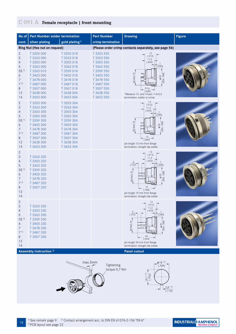
C 091 A Female receptacle | front mounting
No. of Part Number solder termination Part Number Drawing Figurecont. silver plating gold plating1) crimp termination Ring Nut (Hex nut on request) (Please order crimp contacts separately, see page 56)2345 5S 2)
677 2)
81214
T 3203 000T 3263 000T 3303 000T 3363 000T 3363 010T 3403 000T 3478 000T 3487 000T 3507 000T 3638 000T 3653 000
T 3203 018T 3263 018T 3303 018T 3363 018T 3359 018T 3403 018T 3478 018T 3487 018 T 3507 018T 3638 004T 3653 004
T 3203 550T 3263 550T 3303 550T 3363 550T 3359 550 T 3403 550T 3478 550T 3487 550T 3507 550 T 3638 550 T 3653 550
*Measure 12- and 14-pol.=14±0,3termination: solder or crimp
2345 5S 2)
677 2)
81214
T 3203 300T 3263 300 T 3303 300 T 3363 300T 3359 300T 3403 300T 3478 300T 3487 300T 3507 300T 3638 300T 3653 300
T 3203 304T 3263 304T 3303 304T 3363 304T 3359 304T 3403 304T 3478 304T 3487 304T 3507 304T 3638 304 T 3653 304
pin length 15 mm from flangetermination: straight dip solder
2345 5S 2)
677 2)
81214
T 3263 320 T 3303 320T 3363 320T 3359 320 T 3403 320T 3478 320T 3487 320 T 3507 320
pin length 19 mm from flangetermination: straight dip solder
2345 5S 2)
677 2)
81214
T 3263 330 T 3303 330 T 3363 330 T 3359 330 T 3403 330T 3478 330 T 3487 330 T 3507 330
pin length 24 mm from flangetermination: straight dip solder
Assembly instruction 3) Panel cutout
Ma§ bei 12- und 14-pol.=14
16
20(D
IA .7
88)
M18
x0,7
5
(.630)
(.040)1
11,5(.453)
Fig. C 091A-21a13
(.512)
M18
x0,7
5
20(D
IA .7
88)
(.600)15
(.040)1
11,5(.453)
Fig. C 091A-23a13
(.512)
M18
x0,7
5
20(D
IA .7
88)
(.157)4
(.748)19
(.040)1
Fig. C 091A-24a13
(.512)11,5
(.453)20
(DIA
.788
)
(.945)24
(.040)1
Fig. C 091A-25a13
(.512)11,5
(.453)(.157)
4
M18
x0,7
5
18 +0,1
19,1
(.709)
Fig. C 091A-99a
2,8(.110)
+0,1
(.752
)+0
,1
max.5mm
Fig. C 091A-110a
Tightening torque 0,7 Nm
19
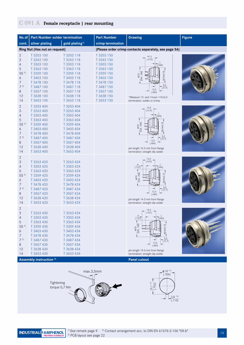
C 091 A Female receptacle | rear mounting
No. of Part Number solder termination Part Number Drawing Figurecont. silver plating gold plating1) crimp termination Ring Nut (Hex nut on request) (Please order crimp contacts separately, see page 56)2345 5S 2)
677 2)
81214
T 3203 100T 3263 100T 3303 100T 3363 100T 3359 100T 3403 100T 3478 100T 3487 100T 3507 100T 3638 100T 3653 100
T 3203 118T 3263 118 T 3303 118 T 3363 118 T 3359 118 T 3403 118 T 3478 118 T 3487 118 T 3507 118 T 3638 118 T 3653 118
T 3203 150T 3263 150 T 3303 150 T 3363 150T 3359 150T 3403 150T 3478 150T 3487 150 T 3507 150T 3638 150 T 3653 150
*Measure 12- and 14-pol.=10±0,3termination: solder or crimp
2345 5S 2)
677 2)
81214
T 3203 400T 3263 400T 3303 400T 3363 400T 3359 400T 3403 400T 3478 400T 3487 400T 3507 400T 3638 400T 3653 400
T 3203 404T 3263 404T 3303 404T 3363 404 T 3359 404T 3403 404T 3478 404 T 3487 404T 3507 404T 3638 404T 3653 404
pin length 10.5 mm from flangetermination: straight dip solder
2345 5S 2)
677 2)
81214
T 3263 420 T 3303 420T 3363 420T 3359 420T 3403 420T 3478 420T 3487 420 T 3507 420T 3638 420T 3653 420
T 3263 424T 3303 424T 3363 424T 3359 424T 3403 424T 3478 424T 3487 424T 3507 424T 3638 424T 3653 424
pin length 14.5 mm from flangetermination: straight dip solder
2345 5S 2)
677 2)
81214
T 3263 430T 3303 430T 3363 430T 3359 430 T 3403 430T 3478 430T 3487 430 T 3507 430T 3638 430T 3653 430
T 3263 434T 3303 434T 3363 434T 3359 434T 3403 434T 3478 434T 3487 434T 3507 434T 3638 434T 3653 434
pin length 19.5 mm from flangetermination: straight dip solder
Assembly instruction 3) Panel cutout
18 +0,1
19,1
(.709)
Fig. C 091A-99a
2,8(.110)
+0,1
(.752
)+0
,1
max.3,5mm
Fig. C 091A-111a
Tightening torque 0,7 Nm
Ma§ bei 12- und 14-pol.=10
12(.472)
(.040)1
(.484)12,5
(.217)5,5
20(D
IA .7
88)
M18
x0,7
5
Fig. C 091A-22a
20(D
IA .7
88)
10,5(.413)
(.040)1
(.484)12,5
(.217)5,5
M18
x0,7
5
Fig. C 091A-26a
(.157)4
20(D
IA .7
88)
14,5(.570)
(.040)1
(.484)12,5
(.217)5,5
M18
x0,7
5
Fig. C 091A-27a
(.157)4
19,5(.767)
(.040)1
M18
x0,7
5
20(D
IA .7
88)
(.217)5,5
(.484)12,5
1) See remark page 9 2) Contact arrangement acc. to DIN EN 61076-2-106 "0X-b" 3) PCB layout see page 22
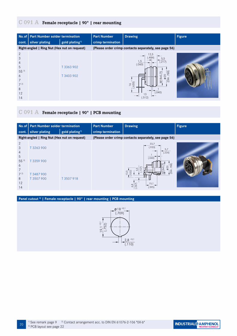
201) See remark page 9 2) Contact arrangement acc. to DIN EN 61076-2-106 "0X-b" 3) PCB layout see page 22
C 091 A Female receptacle | 90° | rear mounting
No. of Part Number solder termination Part Number Drawing Figurecont. silver plating gold plating1) crimp termination Right-angled | Ring Nut (Hex nut on request) (Please order crimp contacts separately, see page 56)2345 5S 2)
677 2)
81214
T 3363 902
T 3403 902
(.217)
(.630
) M18
x0,7
5
(.040)1
12,5(.484) 5,5
(.060)1,5
Fig. C 091A-72a
(.512)
16
20(D
IA .7
88)
13
C 091 A Female receptacle | 90° | PCB mounting
No. of Part Number solder termination Part Number Drawing Figurecont. silver plating gold plating1) crimp termination Right-angled | Ring Nut (Hex nut on request) (Please order crimp contacts separately, see page 56)2345 5S 2)
677 2)
81214
T 3263 900
T 3359 900
T 3487 900T 3507 900 T 3507 918
1(.040)
3,5
6,8
(.267
)
(.933)23,7
(.595)
(.137
)
(DIA
.788
)
M18
x0,7
5
15,1
(.224)
(.532
)13
,5
Fig. C 091A-94a
20
5,7
Panel cutout 3) | Female receptacle | 90° | rear mounting | PCB mounting
18 +0,1
19,1
(.709)
Fig. C 091A-99a
2,8(.110)
+0,1
(.752
)+0
,1
21
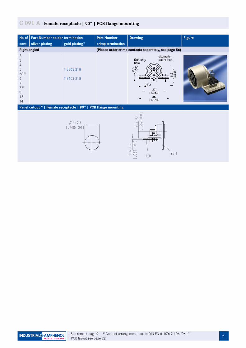
No. of Part Number solder termination Part Number Drawing Figurecont. silver plating gold plating1) crimp termination Right-angled (Please order crimp contacts separately, see page 56)2345 5S 2)
677 2)
81214
T 3363 218
T 3403 218
Panel cutout 3) | Female receptacle | 90° | PCB flange mounting
1) See remark page 9 2) Contact arrangement acc. to DIN EN 61076-2-106 "0X-b"3) PCB layout see page 22
C 091 A Female receptacle | 90° | PCB flange mounting
22 1) Contact arrangement acc. to DIN EN 61076-2-106 "0X-b"
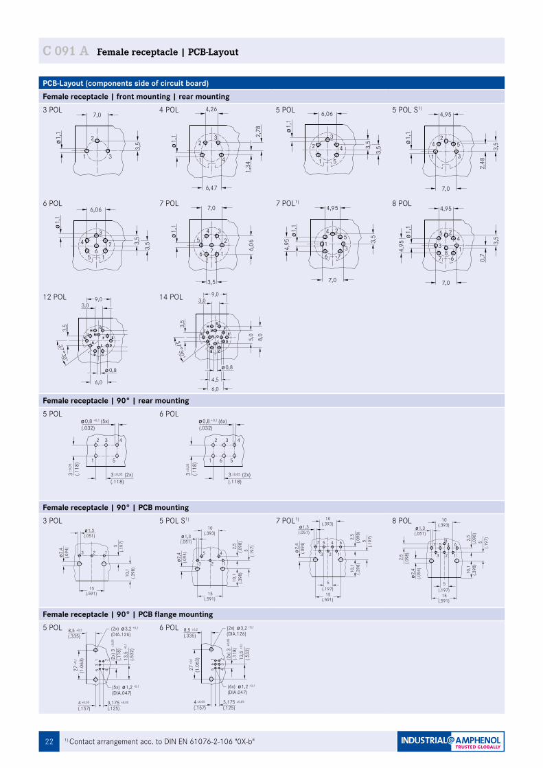
C 091 A Female receptacle | PCB-Layout
PCB-Layout (components side of circuit board)Female receptacle | front mounting | rear mounting3 POL 4 POL 5 POL 5 POL S1)
6 POL 7 POL 7 POL1) 8 POL
12 POL 14 POL
Female receptacle | 90° | rear mounting5 POL 6 POL
Female receptacle | 90° | PCB mounting3 POL 5 POL S1) 7 POL1) 8 POL
Female receptacle | 90° | PCB flange mounting5 POL 6 POL
1
1
4,26
6,47
6,06
3,5
7,0
4,95
5
6,06
3,5
3,5
0,7
3,5
3,5
3,53,
53,
53,
5
4,95
4
3
2
13
2
4
33
2
15
4
42
1
53
2
15
46
3 45
61
2
7
5 2
167
3
24
67
38
F
HJ M
K EA
L D
B C
G
HJ M F
K N OE
A L D
B C
G
3730
4,5
5 Pol. Stereo
4 Pol.
12 Pol.
DIN 45 3226 Pol.
DIN 45 3225 Pol.
DIN 41 5243 Pol.
DIN 45 3297 Pol.
DIN 41 5247 Pol.
DIN 45 3268 Pol.
9,03,0
0,8
6,0
5,0
8,0
3,5
14 Pol.
1,1
1,1
1,1
1,1
2,48
1,1
1,1
4,95
1,34
2,78 1,
11,
1
3,09,0
5,0
8,0
3,5
3730
0,8
6,0
4,95
7,0
7,04,95
7,0
6,067,0
1
1
4,26
6,47
6,06
3,5
7,0
4,95
5
6,06
3,5
3,5
0,7
3,5
3,5
3,53,
53,
53,
5
4,95
4
3
2
13
2
4
33
2
15
4
42
1
53
2
15
46
3 45
61
2
7
5 2
167
3
24
67
38
F
HJ M
K EA
L D
B C
G
HJ M F
K N OE
A L D
B C
G
3730
4,5
5 Pol. Stereo
4 Pol.
12 Pol.
DIN 45 3226 Pol.
DIN 45 3225 Pol.
DIN 41 5243 Pol.
DIN 45 3297 Pol.
DIN 41 5247 Pol.
DIN 45 3268 Pol.
9,03,0
0,8
6,0
5,0
8,0
3,5
14 Pol.
1,1
1,1
1,1
1,1
2,48
1,1
1,1
4,95
1,34
2,78
1,1
1,1
3,09,0
5,0
8,0
3,5
3730
0,8
6,0
4,95
7,0
7,04,95
7,0
6,067,0
3
4
4,26
6,47
6,06
3,5
7,0
4,95
4
6,06
3,5
3,5
0,7
3,5
3,5
3,53,
53,
53,
5
4,95
5
1
2
31
3
1
23
4
51
2
52
3
43
4
51
26
4 32
16
5
7
4 2
376
1
25
76
18
Fig. C 091A-78a
5 Pol. Stereo
4 Pol.
12 Pol.
DIN 45 3226 Pol.
DIN 45 3225 Pol.
DIN 41 5243 Pol.
DIN 45 3297 Pol.
DIN 41 5247 Pol.
DIN 45 3268 Pol.
14 Pol.
1,1
1,1
1,1
1,1
2,48
1,1
1,1
4,95
1,34
2,78 1,
11,
1
4,95
7,0
7,04,95
7,0
6,067,0
contact arrangement acc. to IEC 60 130-9
5,08,0
3730
3,5
3,09,0
6,0
0,8
B C
A L
KJ H
M
G
FE
D
3730
4,6,0
5,0
9,03,0
3,50,8
8,0
BC
LA
KJ H
G
MN
FE
DO
3
4
4,26
6,47
6,06
3,5
7,0
4,95
46,
063,
53,
5
0,7
3,5
3,5
3,53,
53,
53,
5
4,95
5
1
2
31
3
1
23
4
51
2
52
3
43
4
51
26
4 32
16
5
7
4 2
376
1
25
76
18
Fig. C 091A-78a
5 Pol. Stereo
4 Pol.
12 Pol.
DIN 45 3226 Pol.
DIN 45 3225 Pol.
DIN 41 5243 Pol.
DIN 45 3297 Pol.
DIN 41 5247 Pol.
DIN 45 3268 Pol.
14 Pol.
1,1
1,1
1,1
1,1
2,48
1,1
1,1
4,95
1,34
2,78 1,
11,
1
4,95
7,0
7,04,95
7,0
6,067,0
contact arrangement acc. to IEC 60 130-9
5,08,0
3730
3,5
3,09,0
6,0
0,8
B C
A L
KJ H
M
G
FE
D
3730
4,6,0
5,0
9,03,0
3,5
0,8
8,0
BC
LA
KJ H
G
MN
FE
DO
1
1
4,26
6,47
6,06
3,5
7,0
4,95
5
6,06
3,5
3,5
0,7
3,5
3,5
3,53,
53,
53,
5
4,95
4
3
2
13
2
4
33
2
15
4
42
1
53
2
15
46
3 45
61
2
7
5 2
167
3
24
67
38
F
HJ M
K EA
L D
B C
G
HJ M F
K N OE
A L D
B C
G
3730
4,5
5 Pol. Stereo
4 Pol.
12 Pol.
DIN 45 3226 Pol.
DIN 45 3225 Pol.
DIN 41 5243 Pol.
DIN 45 3297 Pol.
DIN 41 5247 Pol.
DIN 45 3268 Pol.
9,03,0
0,8
6,0
5,0
8,0
3,5
14 Pol.
1,1
1,1
1,1
1,1
2,48
1,1
1,1
4,95
1,34
2,78 1,
11,
1
3,09,0
5,0
8,0
3,5
3730
0,8
6,0
4,95
7,0
7,04,95
7,0
6,067,0
3
4
4,26
6,47
6,06
3,5
7,0
4,95
4
6,06
3,5
3,5
0,7
3,5
3,5
3,53,
53,
53,
5
4,95
5
1
2
31
3
1
23
4
51
2
52
3
43
4
51
26
4 32
16
5
7
4 2
376
1
25
76
18
Fig. C 091A-78a
5 Pol. Stereo
4 Pol.
12 Pol.
DIN 45 3226 Pol.
DIN 45 3225 Pol.
DIN 41 5243 Pol.
DIN 45 3297 Pol.
DIN 41 5247 Pol.
DIN 45 3268 Pol.
14 Pol.
1,1
1,1
1,1
1,1
2,48
1,1
1,1
4,95
1,34
2,78 1,
11,
1
4,95
7,0
7,04,95
7,0
6,067,0
contact arrangement acc. to IEC 60 130-9
5,08,0
3730
3,5
3,09,0
6,0
0,8
B C
A L
KJ H
M
G
FE
D
3730
4,6,0
5,0
9,03,0
3,5
0,8
8,0
BC
LA
KJ H
G
MN
FE
DO
3
4
4,26
6,47
6,06
3,5
7,0
4,95
46,
063,
53,
5
0,7
3,5
3,5
3,53,
53,
53,
5
4,95
5
1
2
31
3
1
23
4
51
2
52
3
43
4
51
26
4 32
16
5
7
4 2
376
1
25
76
18
Fig. C 091A-78a
5 Pol. Stereo
4 Pol.
12 Pol.
DIN 45 3226 Pol.
DIN 45 3225 Pol.
DIN 41 5243 Pol.
DIN 45 3297 Pol.
DIN 41 5247 Pol.
DIN 45 3268 Pol.
14 Pol.
1,1
1,1
1,1
1,1
2,48
1,1
1,1
4,95
1,34
2,78 1,
11,
1
4,95
7,0
7,04,95
7,0
6,067,0
contact arrangement acc. to IEC 60 130-9
5,08,0
3730
3,5
3,09,0
6,0
0,8
B C
A L
KJ H
M
G
FE
D
3730
4,6,0
5,0
9,03,0
3,50,8
8,0
BC
LA
KJ H
G
MN
FE
DO
3
4
4,26
6,47
6,06
3,5
7,0
4,95
4
6,06
3,5
3,5
0,7
3,5
3,5
3,53,
53,
53,
5
4,95
5
1
2
31
3
1
23
4
51
2
52
3
43
4
51
26
4 32
16
5
7
4 2
376
1
25
76
18
Fig. C 091A-78a
5 Pol. Stereo
4 Pol.
12 Pol.
DIN 45 3226 Pol.
DIN 45 3225 Pol.
DIN 41 5243 Pol.
DIN 45 3297 Pol.
DIN 41 5247 Pol.
DIN 45 3268 Pol.
14 Pol.
1,1
1,1
1,1
1,1
2,48
1,1
1,1
4,95
1,34
2,78 1,
11,
1
4,95
7,0
7,04,95
7,0
6,067,0
contact arrangement acc. to IEC 60 130-9
5,08,0
3730
3,5
3,09,0
6,0
0,8
B C
A L
KJ H
M
G
FE
D
3730
4,6,0
5,0
9,03,0
3,5
0,8
8,0
BC
LA
KJ H
G
MN
FE
DO
1
1
4,26
6,47
6,06
3,5
7,0
4,95
5
6,06
3,5
3,5
0,7
3,5
3,5
3,53,
53,
53,
5
4,95
4
3
2
13
2
4
33
2
15
4
42
1
53
2
15
46
3 45
61
2
7
5 2
167
3
24
67
38
F
HJ M
K EA
L D
B C
G
HJ M F
K N OE
A L D
B C
G
3730
4,5
5 Pol. Stereo
4 Pol.
12 Pol.
DIN 45 3226 Pol.
DIN 45 3225 Pol.
DIN 41 5243 Pol.
DIN 45 3297 Pol.
DIN 41 5247 Pol.
DIN 45 3268 Pol.
9,03,0
0,8
6,0
5,0
8,0
3,5
14 Pol.
1,1
1,1
1,1
1,1
2,48
1,1
1,1
4,95
1,34
2,78
1,1
1,1
3,09,0
5,0
8,0
3,5
3730
0,8
6,0
4,95
7,0
7,04,95
7,0
6,067,0
(DIA.047)
(DIA.126)
56
1
42
3
53
1
5 Pol. 6 Pol.
Fig. C 091A-70a
4(.157)
±0,05
±0,2
±0,1
(2x)
3(.1
18)±0
,05
13,5
(.532
)
27 (1.0
63)
±0,1
8,5(.335)
3,175(.125)
±0,05
+0,1(5x)(DIA.047)
42
+0,1
4(.157)
±0,05
±0,2
±0,1
(2x)
3(.1
18)±0
,05
13,5
(.532
)
27 (1.0
63)
±0,1
8,5(.335)
3,175(.125)
±0,05
(2x)(DIA.126)
3,2+0,1(2x) 3,2
1,2 +0,1(6x) 1,2(DIA.047)
(DIA.126)
56
1
42
3
53
1
5 Pol. 6 Pol.
Fig. C 091A-70a
4(.157)
±0,05
±0,2
±0,1
(2x)
3(.1
18)±0
,05
13,5
(.532
)
27 (1.0
63)
±0,1
8,5(.335)
3,175(.125)
±0,05
+0,1(5x)(DIA.047)
42
+0,1
4(.157)
±0,05
±0,2
±0,1
(2x)
3(.1
18)±0
,05
13,5
(.532
)
27 (1.0
63)
±0,1
8,5(.335)
3,175(.125)
±0,05
(2x)(DIA.126)
3,2+0,1(2x) 3,2
1,2 +0,1(6x) 1,2
2,4
1,3
2,4
1,3
2 13
84 657
45
13
7 645
13 2
10(.393)
(.051)
2,5
(.197)5
5(.1
97)
10,1
(.051)
(.094
)
15(.591)
Fig. C 091A-73a
(.398
)
15(.591)
(.098
)10
,1(.3
98)
2
3 2 1
5(.1
97)
(.197)5
15(.591)
2,5
(.098
)10
,1(.3
98)
5(.1
97)
10(.393)
(.094
)
(.098
)2,
5
2,5
(.098
)10
,1(.3
98)
5(.1
97)
10(.393)
3 Pol.Lochbild fŸr Leiterplatte
7 Pol.
5 Pol. Stereo
8 Pol.
15(.591)
2,4
(.094
)
2,4
(.094
)
1,3(.051)
1,3(.051)
2,4
1,3
2,4
1,3
2 13
84 657
45
13
7 645
13 2
10(.393)
(.051)
2,5
(.197)5
5(.1
97)
10,1
(.051)
(.094
)
15(.591)
Fig. C 091A-73a
(.398
)
15(.591)
(.098
)10
,1(.3
98)
2
3 2 1
5(.1
97)
(.197)5
15(.591)
2,5
(.098
)10
,1(.3
98)
5(.1
97)
10(.393)
(.094
)
(.098
)2,
5
2,5
(.098
)10
,1(.3
98)
5(.1
97)
10(.393)
3 Pol.Lochbild fŸr Leiterplatte
7 Pol.
5 Pol. Stereo
8 Pol.
15(.591)
2,4
(.094
)
2,4
(.094
)
1,3(.051)
1,3(.051)
43
±0,0
53
±0,0
53
6 51
2 3 4
(.118
)
(.118)±0,053 (2x)
(5x)+0,1
51
2
0,8(.032)
5 Pol.
(.118
)
(.118)±0,053 (2x)
Fig. C 091A-71a
(6x)+0,10,8(.032)
43
±0,0
53
±0,0
53
6 51
2 3 4
(.118
)
(.118)±0,053 (2x)
(5x)+0,1
51
2
0,8(.032)
5 Pol.
(.118
)
(.118)±0,053 (2x)
Fig. C 091A-71a
(6x)+0,10,8(.032)

23
C 091 Your Notes
24
C 091
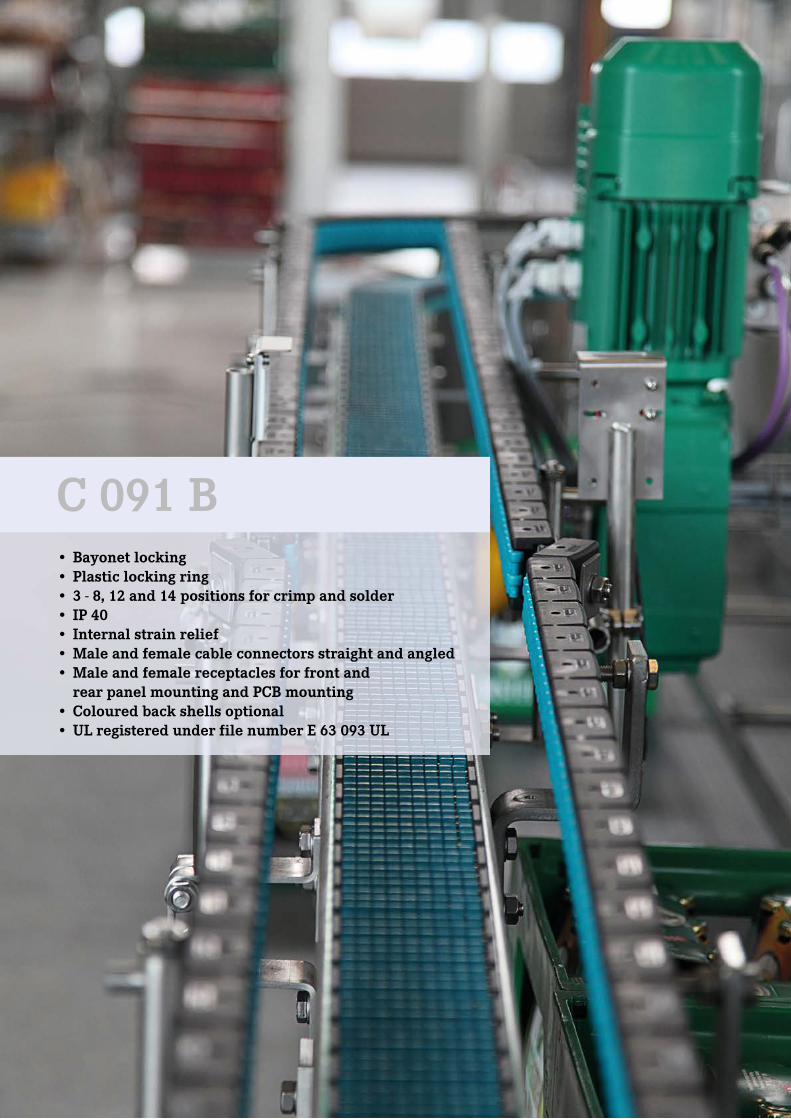
• Bayonet locking• Plastic locking ring• 3 - 8, 12 and 14 positions for crimp and solder • IP 40• Internal strain relief• Male and female cable connectors straight and angled• Male and female receptacles for front and rear panel mounting and PCB mounting • Coloured back shells optional• UL registered under file number E 63 093 UL
C 091 B
25
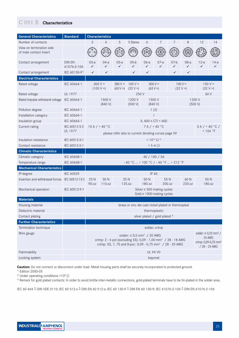
C 091 B Characteristics
General Characteristics Standard CharacteristicsNumber of contacts 3 4 5 5 Stereo 6 7 7 8 12 14View on termination sideof male contact insert
Contact arrangement DIN EN 61076-2-106
03-aü
04-aü
05-aü
05-bü
06-aü
07-aü
07-bü
08-aü
12-aü
14-aü
Contact arrangement IEC 60130-91) ü ü ü ü ü ü
Electrical CharacteristicsRated voltage IEC 60664-1 300 V ≃
(100 V ≃)300 V ≃(63 V ≃)
100 V ≃(32 V ≃)
300 V ≃(63 V ≃)
100 V ≃(32 V ≃)
150 V ≃(32 V ≃)
Rated voltage UL 1977 250 V 60 VRated impulse withstand voltage IEC 60664-1 1500 V
(840 V)1200 V(500 V)
1500 V(840 V)
1200 V(500 V)
Pollution degree IEC 60664-1 1 (2)Installation category IEC 60664-1 IInsulation group IEC 60664-1 II, 400 ≤ CTI < 600Current rating IEC 60512-5-2
UL 197710 A / + 40 °C 7 A / + 40 °C 3 A / + 40 °C /
+ 104 °Fplease refer also to current derating curves page 59
Insulation resistance IEC 60512-3-1 > 1010 Ω 2) Contact resistance IEC 60512-2-1 < 5 m ΩClimatic CharacteristicsClimatic category IEC 60668-1 40 / 100 / 56Temperature range IEC 60668-1 - 40 °C ... + 100 °C / - 40 °F ... + 212 °FMechanical CharacteristicsIP-degree IEC 60529 IP 40Insertion and withdrawal forces IEC 60512-13-2 25 N
90.oz30 N
110.oz35 N
125.oz50 N
180.oz55 N
200.oz60 N
220.oz50 N
180.ozMechanical operation IEC 60512-9-1 Silver ≥ 500 mating cycles
Gold ≥ 1000 mating cyclesMaterialsHousing material brass or zinc die cast nickel plated or thermoplastDielectric material thermoplasticContact plating silver plated / gold plated 3)
Further CharacteristicsTermination technique solder, crimpWire gauge solder: ≤ 0,5 mm2 / 20 AWG
crimp: 2 - 6 pol (excluding 5S): 0,09 - 1,00 mm2 / 28 - 18 AWGcrimp: 5S, 7, 7S and 8-pol.: 0,09 - 0,75 mm2 / 28 - 20 AWG
solder: ≤ 0,25 mm² / 24 AWG
crimp: 0,09-0,25 mm² / 28 – 24 AWG
Flammability UL 94 V0Locking system bayonet
2
2 + 3
31 1
2 3
4
4
4
5
32
1
5 5 Stereo
5
3
4
1
2 4
5
32
16
6
16 7 2
5 34
7
37
21
6
54
7
8
2
8
5
3
4
176
L CD
B
NA
OEF
MK
JH
G
14
L CD
BAEF
MK
JH
G
12
Caution: Do not connect or disconnect under load. Metal housing parts shall be securely incorporated to protected ground.1) Edition 2000-052) Under operating conditions >108 Ω3) Remark for gold plated contacts: In order to avoid brittle inter-metallic connections, gold-plated terminals have to be tin-plated in the solder area.
IEC 60 664 = DIN VDE 0110; IEC 60 512-x = DIN EN 60 512-x; IEC 60 130-9 = DIN EN 60 130-9; IEC 61076-2-106 = DIN EN 61076-2-106
26 1) See remark page 25 2) Contact arrangement acc. to DIN EN 61076-2-106 "0X-b"
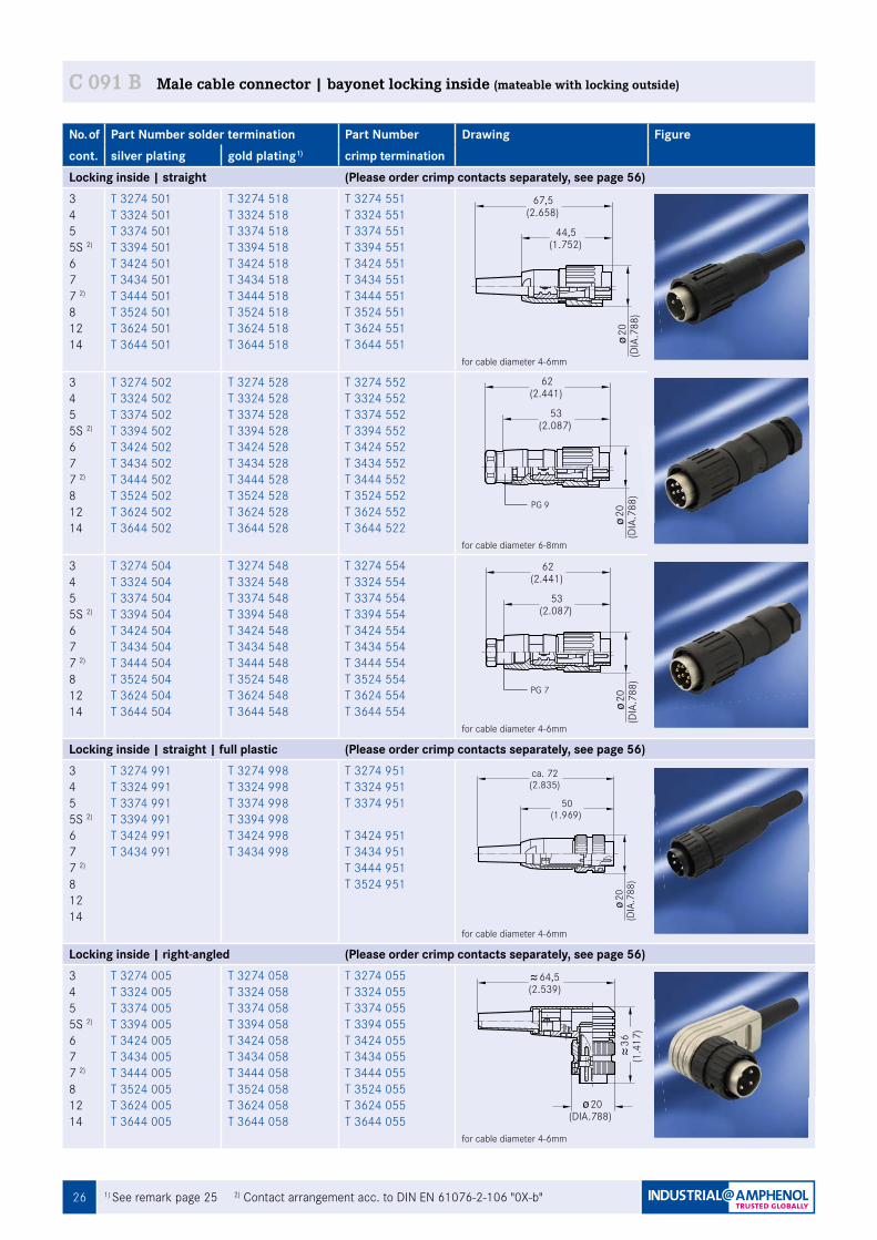
C 091 B Male cable connector | bayonet locking inside (mateable with locking outside)
No. of Part Number solder termination Part Number Drawing Figurecont. silver plating gold plating1) crimp termination Locking inside | straight (Please order crimp contacts separately, see page 56)345 5S 2)
677 2)
81214
T 3274 501T 3324 501T 3374 501T 3394 501T 3424 501T 3434 501T 3444 501T 3524 501T 3624 501T 3644 501
T 3274 518 T 3324 518T 3374 518 T 3394 518T 3424 518T 3434 518 T 3444 518 T 3524 518 T 3624 518 T 3644 518
T 3274 551T 3324 551T 3374 551T 3394 551T 3424 551T 3434 551T 3444 551 T 3524 551T 3624 551T 3644 551
for cable diameter 4-6mm
345 5S 2)
677 2)
81214
T 3274 502T 3324 502T 3374 502T 3394 502T 3424 502T 3434 502T 3444 502 T 3524 502T 3624 502T 3644 502
T 3274 528 T 3324 528 T 3374 528 T 3394 528 T 3424 528 T 3434 528 T 3444 528 T 3524 528T 3624 528 T 3644 528
T 3274 552 T 3324 552T 3374 552 T 3394 552 T 3424 552T 3434 552 T 3444 552 T 3524 552 T 3624 552T 3644 522
for cable diameter 6-8mm
345 5S 2)
677 2)
81214
T 3274 504 T 3324 504 T 3374 504 T 3394 504 T 3424 504 T 3434 504 T 3444 504 T 3524 504 T 3624 504 T 3644 504
T 3274 548 T 3324 548T 3374 548 T 3394 548 T 3424 548T 3434 548 T 3444 548 T 3524 548T 3624 548 T 3644 548
T 3274 554 T 3324 554 T 3374 554 T 3394 554 T 3424 554 T 3434 554 T 3444 554 T 3524 554 T 3624 554T 3644 554
for cable diameter 4-6mm
Locking inside | straight | full plastic (Please order crimp contacts separately, see page 56)345 5S 2)
677 2)
81214
T 3274 991T 3324 991T 3374 991T 3394 991 T 3424 991T 3434 991
T 3274 998T 3324 998T 3374 998T 3394 998 T 3424 998T 3434 998
T 3274 951T 3324 951T 3374 951
T 3424 951T 3434 951T 3444 951T 3524 951
for cable diameter 4-6mm
Locking inside | right-angled (Please order crimp contacts separately, see page 56)345 5S 2)
677 2)
81214
T 3274 005T 3324 005T 3374 005T 3394 005T 3424 005T 3434 005T 3444 005 T 3524 005T 3624 005T 3644 005
T 3274 058 T 3324 058 T 3374 058T 3394 058 T 3424 058 T 3434 058 T 3444 058 T 3524 058 T 3624 058 T 3644 058
T 3274 055 T 3324 055 T 3374 055T 3394 055 T 3424 055T 3434 055 T 3444 055 T 3524 055T 3624 055T 3644 055
for cable diameter 4-6mm
44,5(1.752)
67,5(2.658)
20(D
IA.7
88)
Fig. C 091B-9a
Fig. C 091B-10a
53(2.087)
62(2.441)
20(D
IA.7
88)
53(2.087)
62(2.441)
20(D
IA.7
88)
Fig. C 091B-11a
ca. 72
50(1.969)
(2.835)
20(D
IA.7
88)
Fig. C 091B-54a
(DIA.788)20
36(1
.417
)
64,5(2.539)
Fig. C 091B-43a
PG 9
PG 7
271) For further information see page 60 2) Solder version only
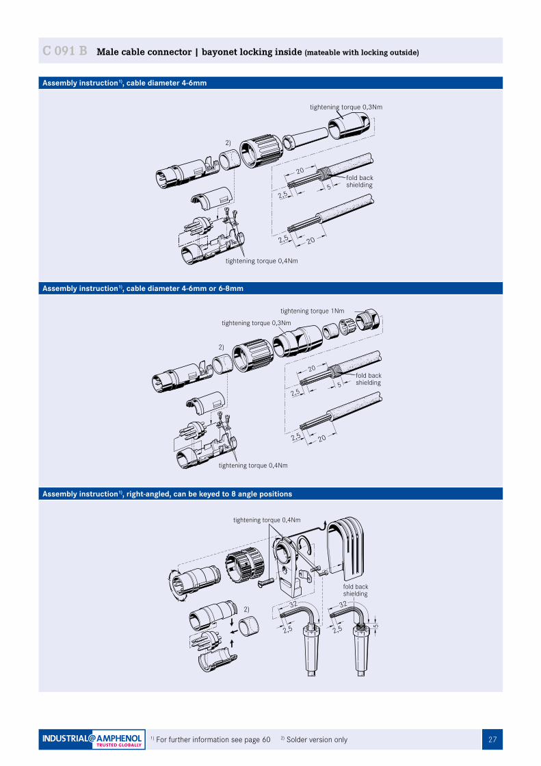
C 091 B Male cable connector | bayonet locking inside (mateable with locking outside)
Assembly instruction1), cable diameter 4-6mm
Assembly instruction1), cable diameter 4-6mm or 6-8mm
Assembly instruction1), right-angled, can be keyed to 8 angle positions
20
2,5 20
2,55
fold backshielding
tightening torque 0,4Nm
tightening torque 0,3Nm
2,5 20
20
2,55
fold backshielding
tightening torque 0,4Nm
tightening torque 1Nm
tightening torque 0,3Nm
2,5
32
2,5
32
5
fold backshielding
tightening torque 0,4Nm
2)
2)
2)
28 1) See remark page 25 2) Contact arrangement acc. to DIN EN 61076-2-106 "0X-b"
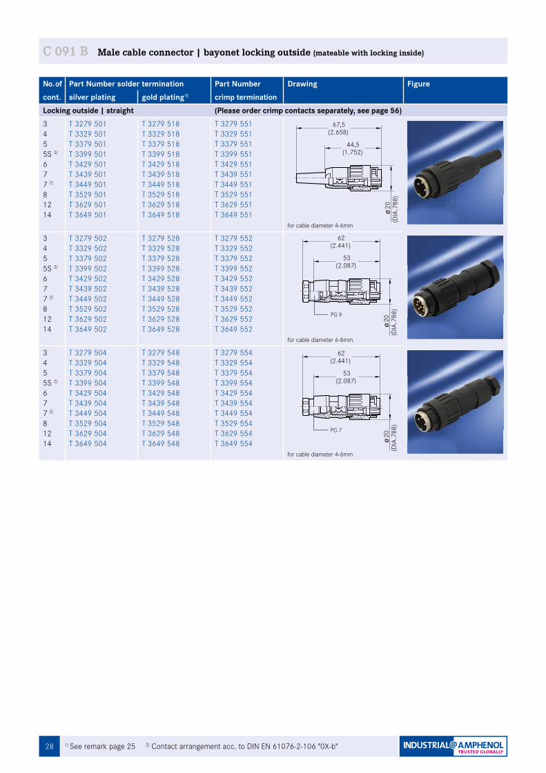
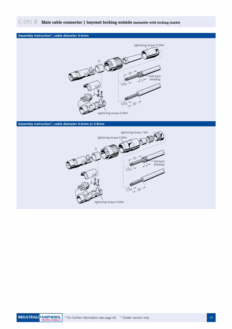
C 091 B Male cable connector | bayonet locking outside (mateable with locking inside)
No. of Part Number solder termination Part Number Drawing Figurecont. silver plating gold plating1) crimp termination Locking outside | straight (Please order crimp contacts separately, see page 56)345 5S 2)
677 2)
81214
T 3279 501T 3329 501T 3379 501T 3399 501 T 3429 501T 3439 501T 3449 501 T 3529 501 T 3629 501 T 3649 501
T 3279 518 T 3329 518 T 3379 518 T 3399 518 T 3429 518 T 3439 518 T 3449 518 T 3529 518 T 3629 518 T 3649 518
T 3279 551 T 3329 551T 3379 551T 3399 551 T 3429 551T 3439 551T 3449 551 T 3529 551 T 3629 551T 3649 551
for cable diameter 4-6mm
345 5S 2)
677 2)
81214
T 3279 502T 3329 502T 3379 502T 3399 502 T 3429 502 T 3439 502 T 3449 502 T 3529 502 T 3629 502 T 3649 502
T 3279 528 T 3329 528 T 3379 528 T 3399 528 T 3429 528 T 3439 528 T 3449 528 T 3529 528 T 3629 528 T 3649 528
T 3279 552 T 3329 552 T 3379 552 T 3399 552 T 3429 552 T 3439 552 T 3449 552 T 3529 552 T 3629 552T 3649 552
for cable diameter 6-8mm
345 5S 2)
677 2)
81214
T 3279 504 T 3329 504 T 3379 504 T 3399 504 T 3429 504 T 3439 504 T 3449 504 T 3529 504 T 3629 504 T 3649 504
T 3279 548 T 3329 548 T 3379 548 T 3399 548 T 3429 548 T 3439 548 T 3449 548 T 3529 548 T 3629 548 T 3649 548
T 3279 554 T 3329 554 T 3379 554 T 3399 554 T 3429 554 T 3439 554 T 3449 554 T 3529 554 T 3629 554T 3649 554
for cable diameter 4-6mm
44,5(1.752)
67,5(2.658)
20(D
IA.7
88)
Fig. C 091B-18a
53(2.087)
62(2.441)
20(D
IA.7
88)
Fig. C 091B-19a
53(2.087)
62(2.441)
20(D
IA.7
88)
Fig. C 091B-20a
PG 9
PG 7
291) For further information see page 60 2) Solder version only
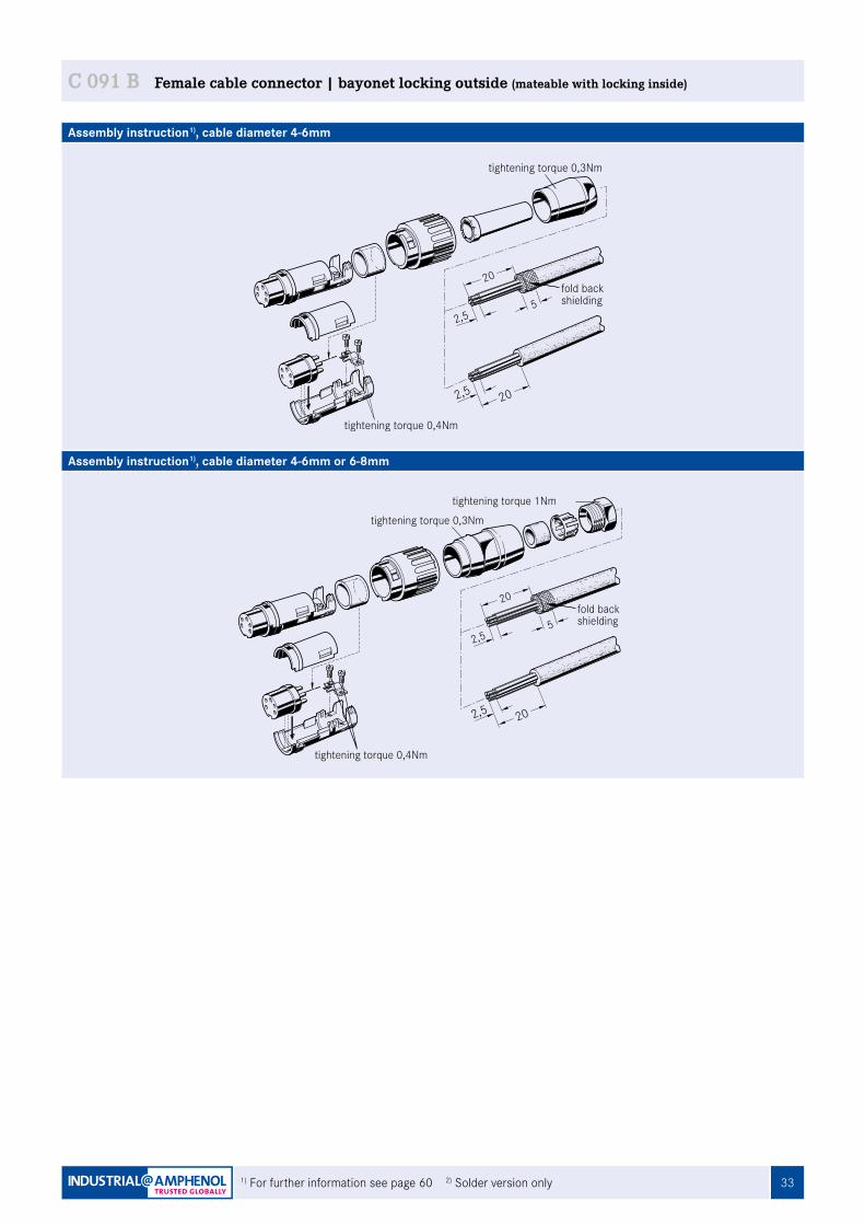
C 091 B Male cable connector | bayonet locking outside (mateable with locking inside)
Assembly instruction1), cable diameter 4-6mm
Assembly instruction1), cable diameter 4-6mm or 6-8mm
2,5 20
20
2,55
fold backshielding
tightening torque 0,3Nm
tightening torque 0,4Nm
2,5 20
20
2,55
fold backshielding
tightening torque 1Nm
tightening torque 0,3Nm
tightening torque 0,4Nm
2)
2)
30
C 091
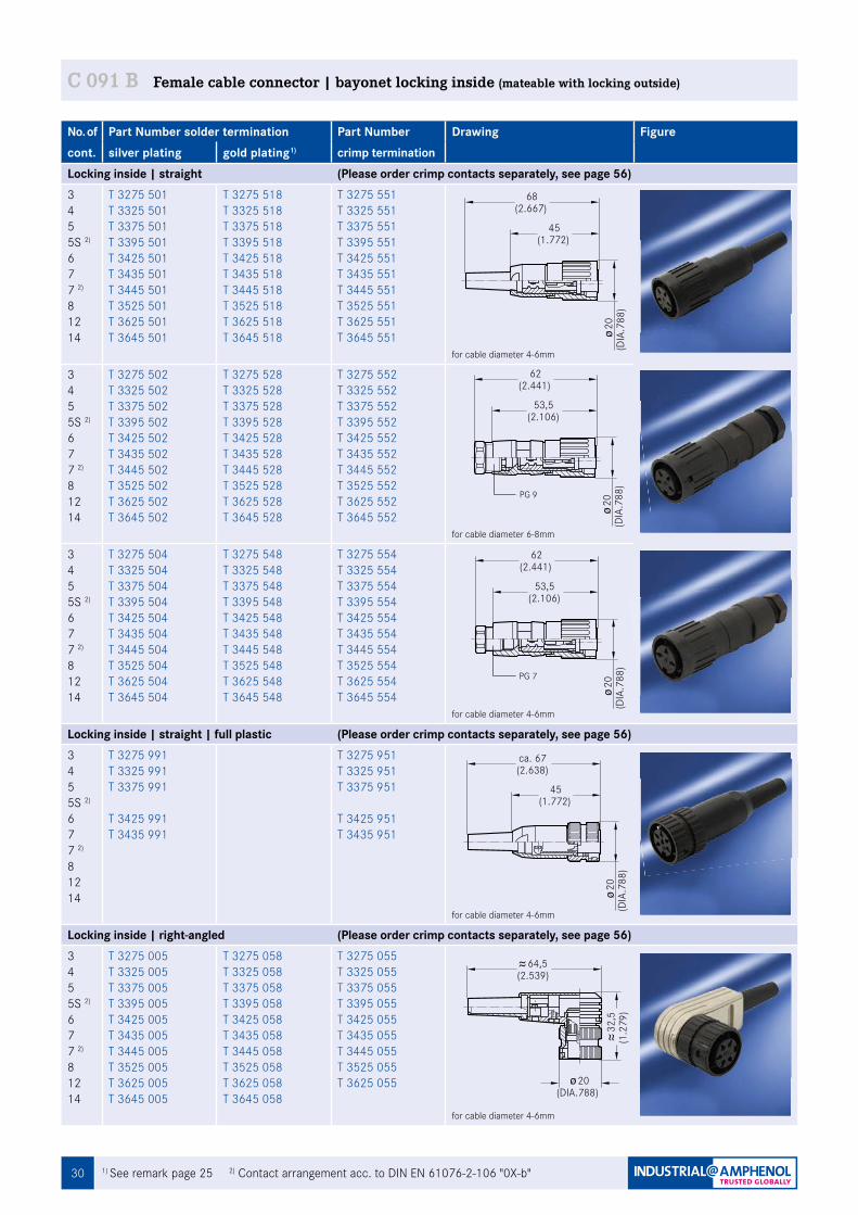
No. of Part Number solder termination Part Number Drawing Figurecont. silver plating gold plating1) crimp termination Locking inside | straight (Please order crimp contacts separately, see page 56)345 5S 2)
677 2)
81214
T 3275 501T 3325 501T 3375 501T 3395 501 T 3425 501T 3435 501T 3445 501 T 3525 501 T 3625 501 T 3645 501
T 3275 518 T 3325 518T 3375 518 T 3395 518 T 3425 518T 3435 518 T 3445 518 T 3525 518 T 3625 518 T 3645 518
T 3275 551T 3325 551T 3375 551T 3395 551 T 3425 551T 3435 551 T 3445 551 T 3525 551 T 3625 551T 3645 551
for cable diameter 4-6mm
345 5S 2)
677 2)
81214
T 3275 502 T 3325 502 T 3375 502 T 3395 502 T 3425 502T 3435 502 T 3445 502 T 3525 502 T 3625 502 T 3645 502
T 3275 528 T 3325 528 T 3375 528 T 3395 528 T 3425 528 T 3435 528 T 3445 528 T 3525 528 T 3625 528 T 3645 528
T 3275 552 T 3325 552 T 3375 552 T 3395 552 T 3425 552 T 3435 552 T 3445 552 T 3525 552 T 3625 552T 3645 552
for cable diameter 6-8mm
345 5S 2)
677 2)
81214
T 3275 504 T 3325 504 T 3375 504 T 3395 504 T 3425 504 T 3435 504 T 3445 504 T 3525 504 T 3625 504 T 3645 504
T 3275 548 T 3325 548 T 3375 548 T 3395 548 T 3425 548 T 3435 548 T 3445 548 T 3525 548 T 3625 548 T 3645 548
T 3275 554 T 3325 554 T 3375 554 T 3395 554 T 3425 554 T 3435 554 T 3445 554 T 3525 554 T 3625 554T 3645 554
for cable diameter 4-6mm
Locking inside | straight | full plastic (Please order crimp contacts separately, see page 56)345 5S 2)
677 2)
81214
T 3275 991 T 3325 991T 3375 991
T 3425 991T 3435 991
T 3275 951 T 3325 951 T 3375 951
T 3425 951 T 3435 951
for cable diameter 4-6mm
Locking inside | right-angled (Please order crimp contacts separately, see page 56)345 5S 2)
677 2)
81214
T 3275 005 T 3325 005 T 3375 005T 3395 005 T 3425 005 T 3435 005T 3445 005 T 3525 005T 3625 005 T 3645 005
T 3275 058 T 3325 058 T 3375 058 T 3395 058 T 3425 058 T 3435 058 T 3445 058 T 3525 058 T 3625 058 T 3645 058
T 3275 055 T 3325 055 T 3375 055 T 3395 055 T 3425 055 T 3435 055 T 3445 055 T 3525 055 T 3625 055
for cable diameter 4-6mm
45(1.772)
68(2.667)
20(D
IA.7
88)
Fig. C 091B-12a
53,5(2.106)
62(2.441)
20(D
IA.7
88)
Fig. C 091B-13a
53,5(2.106)
62(2.441)
20(D
IA.7
88)
Fig. C 091B-14a
(DIA.788)20
32,5
(1.2
79)
64,5(2.539)
Fig. C 091B-47a
1) See remark page 25 2) Contact arrangement acc. to DIN EN 61076-2-106 "0X-b"
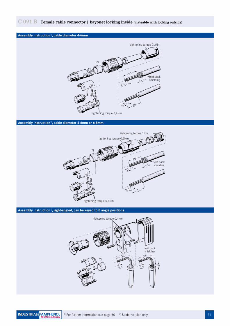
C 091 B Female cable connector | bayonet locking inside (mateable with locking outside)
PG 7
PG 9
ca. 67
45(1.772)
(2.638)
20(D
IA.7
88)
Fig. C 091B-53a
31
C 091
Assembly instruction1), cable diameter 4-6mm
Assembly instruction1), cable diameter 4-6mm or 6-8mm
Assembly instruction1), right-angled, can be keyed to 8 angle positions
2,5 20
20
2,55
fold backshielding
tightening torque 0,4Nm
tightening torque 0,3Nm
2,5 20
20
2,55
fold backshielding
tightening torque 1Nm
tightening torque 0,3Nm
tightening torque 0,4Nm
2,5
32
2,5
32
5
fold backshielding
tightening torque 0,4Nm
1) For further information see page 60 2) Solder version only
C 091 B Female cable connector | bayonet locking inside (mateable with locking outside)
2)
2)
2)
32
C 091
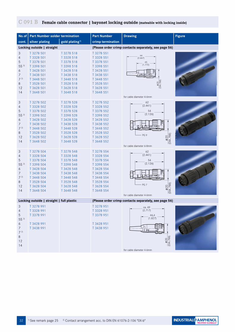
No. of Part Number solder termination Part Number Drawing Figurecont. silver plating gold plating1) crimp termination Locking outside | straight (Please order crimp contacts separately, see page 56)345 5S 2)
677 2)
81214
T 3278 501T 3328 501T 3378 501T 3398 501T 3428 501T 3438 501T 3448 501 T 3528 501T 3628 501 T 3648 501
T 3278 518T 3328 518 T 3378 518 T 3398 518T 3428 518T 3438 518 T 3448 518 T 3528 518 T 3628 518 T 3648 518
T 3278 551 T 3328 551 T 3378 551T 3398 551 T 3428 551T 3438 551T 3448 551 T 3528 551 T 3628 551T 3648 551
for cable diameter 4-6mm
345 5S 2)
677 2)
81214
T 3278 502T 3328 502T 3378 502 T 3398 502 T 3428 502 T 3438 502 T 3448 502 T 3528 502T 3628 502 T 3648 502
T 3278 528 T 3328 528 T 3378 528 T 3398 528 T 3428 528 T 3438 528 T 3448 528 T 3528 528 T 3628 528 T 3648 528
T 3278 552 T 3328 552T 3378 552 T 3398 552 T 3428 552 T 3438 552 T 3448 552 T 3528 552 T 3628 552T 3648 552
for cable diameter 6-8mm
345 5S 2)
677 2)
81214
T 3278 504 T 3328 504 T 3378 504 T 3398 504 T 3428 504 T 3438 504 T 3448 504 T 3528 504 T 3628 504 T 3648 504
T 3278 548 T 3328 548 T 3378 548 T 3398 548 T 3428 548 T 3438 548 T 3448 548 T 3528 548 T 3628 548 T 3648 548
T 3278 554 T 3328 554 T 3378 554 T 3398 554 T 3428 554 T 3438 554 T 3448 554 T 3528 554 T 3628 554T 3648 554
for cable diameter 4-6mm
Locking outside | straight | full plastic (Please order crimp contacts separately, see page 56)345 5S 2)
677 2)
81214
T 3278 991 T 3328 991 T 3378 991
T 3428 991T 3438 991
T 3278 951 T 3328 951T 3378 951
T 3428 951T 3438 951
for cable diameter 4-6mm
45(1.772)
68(2.667)
20(D
IA.7
88)
Fig. C 091B-15a
54(2.126)
62(2.441)
20(D
IA.7
88)
Fig. C 091B-16a
54(2.126)
62(2.441)
20(D
IA.7
88)
Fig. C 091B-17a
C 091 B Female cable connector | bayonet locking outside (mateable with locking inside)
PG 7
PG 9
ca. 69
46,4(1.827)
(2.717)
20(D
IA.7
88)
Fig. C 091B-59a
1) See remark page 25 2) Contact arrangement acc. to DIN EN 61076-2-106 "0X-b"
33
C 091
Assembly instruction1), cable diameter 4-6mm
Assembly instruction1), cable diameter 4-6mm or 6-8mm
C 091 B Female cable connector | bayonet locking outside (mateable with locking inside)
1) For further information see page 60 2) Solder version only
2,5 20
20
2,55
fold backshielding
tightening torque 0,4Nm
tightening torque 0,3Nm
2,5 20
20
2,55
fold backshielding
tightening torque 1Nm
tightening torque 0,3Nm
tightening torque 0,4Nm
34 1) See remark page 25 2) Contact arrangement acc. to DIN EN 61076-2-106 "0X-b"
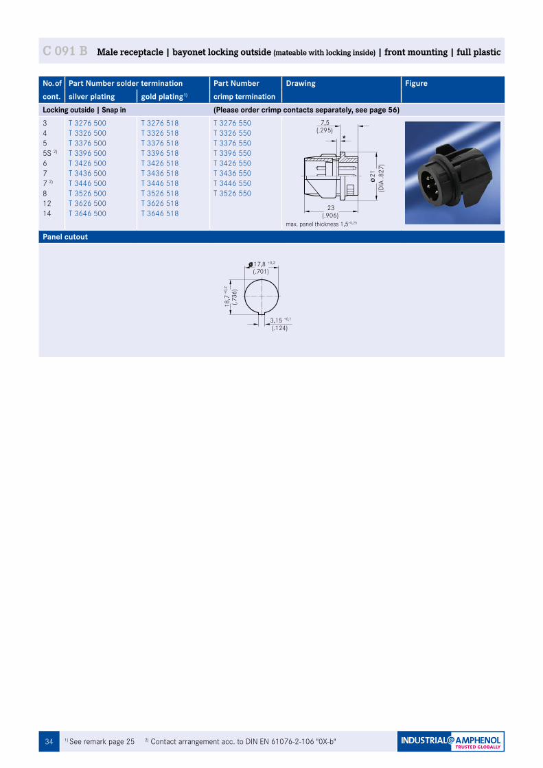
C 091 B Male receptacle | bayonet locking outside (mateable with locking inside) | front mounting | full plastic
No. of Part Number solder termination Part Number Drawing Figurecont. silver plating gold plating1) crimp termination Locking outside | Snap in (Please order crimp contacts separately, see page 56)345 5S 2)
677 2)
81214
T 3276 500T 3326 500T 3376 500T 3396 500 T 3426 500T 3436 500T 3446 500 T 3526 500 T 3626 500 T 3646 500
T 3276 518 T 3326 518 T 3376 518 T 3396 518 T 3426 518 T 3436 518T 3446 518 T 3526 518 T 3626 518 T 3646 518
T 3276 550T 3326 550T 3376 550T 3396 550 T 3426 550T 3436 550T 3446 550 T 3526 550
max. panel thickness 1,5+0,25
Panel cutout
17,8 +0,2
18,7
(.701)
Fig. C 091B-100a
3,15(.124)
+0,1
(.736
)+0,2
Fig. C 091B-85a
+0,25WandstŠrke max. 1,5
(DIA
.827
)21
(.906)23
(.295)7,5
351) See remark page 25 2) Contact arrangement acc. to DIN EN 61076-2-106 "0X-b"
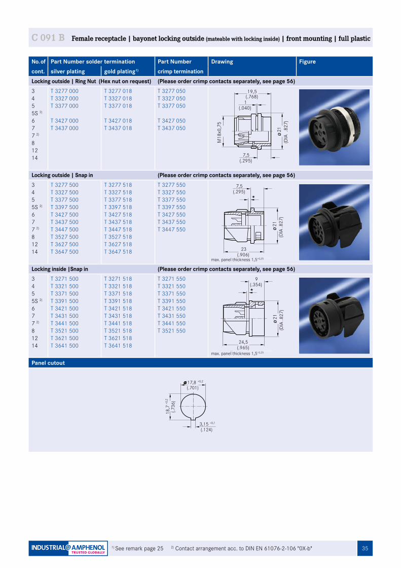
C 091 B Female receptacle | bayonet locking outside (mateable with locking inside) | front mounting | full plastic
No. of Part Number solder termination Part Number Drawing Figurecont. silver plating gold plating1) crimp termination Locking outside | Ring Nut (Hex nut on request) (Please order crimp contacts separately, see page 56)345 5S 2)
677 2)
81214
T 3277 000T 3327 000T 3377 000
T 3427 000T 3437 000
T 3277 018 T 3327 018 T 3377 018
T 3427 018 T 3437 018
T 3277 050T 3327 050T 3377 050
T 3427 050T 3437 050
Locking outside | Snap in (Please order crimp contacts separately, see page 56)345 5S 2)
677 2)
81214
T 3277 500T 3327 500T 3377 500T 3397 500T 3427 500T 3437 500T 3447 500T 3527 500T 3627 500T 3647 500
T 3277 518 T 3327 518 T 3377 518 T 3397 518 T 3427 518 T 3437 518 T 3447 518 T 3527 518 T 3627 518 T 3647 518
T 3277 550T 3327 550T 3377 550T 3397 550 T 3427 550T 3437 550T 3447 550
max. panel thickness 1,5+0,25
Locking inside |Snap in (Please order crimp contacts separately, see page 56)345 5S 2)
677 2)
81214
T 3271 500 T 3321 500 T 3371 500 T 3391 500 T 3421 500T 3431 500T 3441 500 T 3521 500 T 3621 500 T 3641 500
T 3271 518 T 3321 518 T 3371 518 T 3391 518 T 3421 518 T 3431 518 T 3441 518 T 3521 518 T 3621 518 T 3641 518
T 3271 550 T 3321 550 T 3371 550 T 3391 550 T 3421 550 T 3431 550 T 3441 550 T 3521 550
max. panel thickness 1,5+0,25
Panel cutout
19,5Fig. C 091B-79a
M18
x0,7
5
(DIA
.827
)21
(.040)1
(.295)7,5
(.768)
+0,25
Fig. C 091B-80a
WandstŠrke max. 1,5
(DIA
.827
)21
(.295)7,5
(.906)23
9(.354)
Fig. C 091B-81a
+0,25WandstŠrke max. 1,5
(DIA
.827
)21
24,5(.965)
17,8 +0,2
18,7
(.701)
Fig. C 091B-100a
3,15(.124)
+0,1
(.736
)+0,2

36 1) See remark page 25 2) Contact arrangement acc. to DIN EN 61076-2-106 "0X-b"
C 091 B Female receptacle | bayonet locking outside (mateable with locking inside) | rear mounting | metal
No. of Part Number solder termination Part Number Drawing Figurecont. silver plating gold plating1) crimp termination Locking outside | Ring Nut (Hex nut on request) (Please order crimp contacts separately, see page 56)345 5S 2)
677 2)
81214
T 3277 100T 3327 100T 3377 100T 3397 100T 3427 100T 3437 100 T 3447 100T 3527 100T 3627 100 T 3647 100
T 3277 118T 3327 118T 3377 118T 3397 118T 3427 118T 3437 118T 3447 118T 3527 118T 3627 118T 3647 118
T 3277 150 T 3327 150 T 3377 150 T 3397 150 T 3427 150 T 3437 150 T 3447 150 T 3527 150
Panel cutout
M18
x0,7
5
6,6(.260)
13,6(.535)
(DIA
.788
)20
12(.472)
Fig. C 091B-82a
Montageausschnitt siehe Seite 17
1(.040)
18 +0,1
19,1
(.709)
Fig. C 091A-99a
2,8(.110)
+0,1
(.752
)+0
,1
37
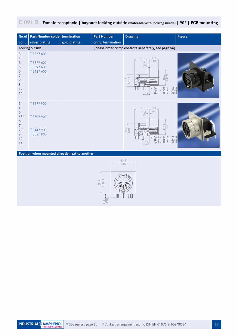
Position when mounted directly next to another
1) See remark page 25 2) Contact arrangement acc. to DIN EN 61076-2-106 "0X-b"
C 091 B Female receptacle | bayonet locking outside (mateable with locking inside) | 90° | PCB mounting
No. of Part Number solder termination Part Number Drawing Figurecont. silver plating gold plating1) crimp termination Locking outside (Please order crimp contacts separately, see page 56)345 5S 2)
677 2)
81214
T 3277 600
T 3377 600T 3397 600T 3427 600
345 5S 2)
677 2)
81214
T 3277 900
T 3397 900
T 3447 900T 3527 900
38
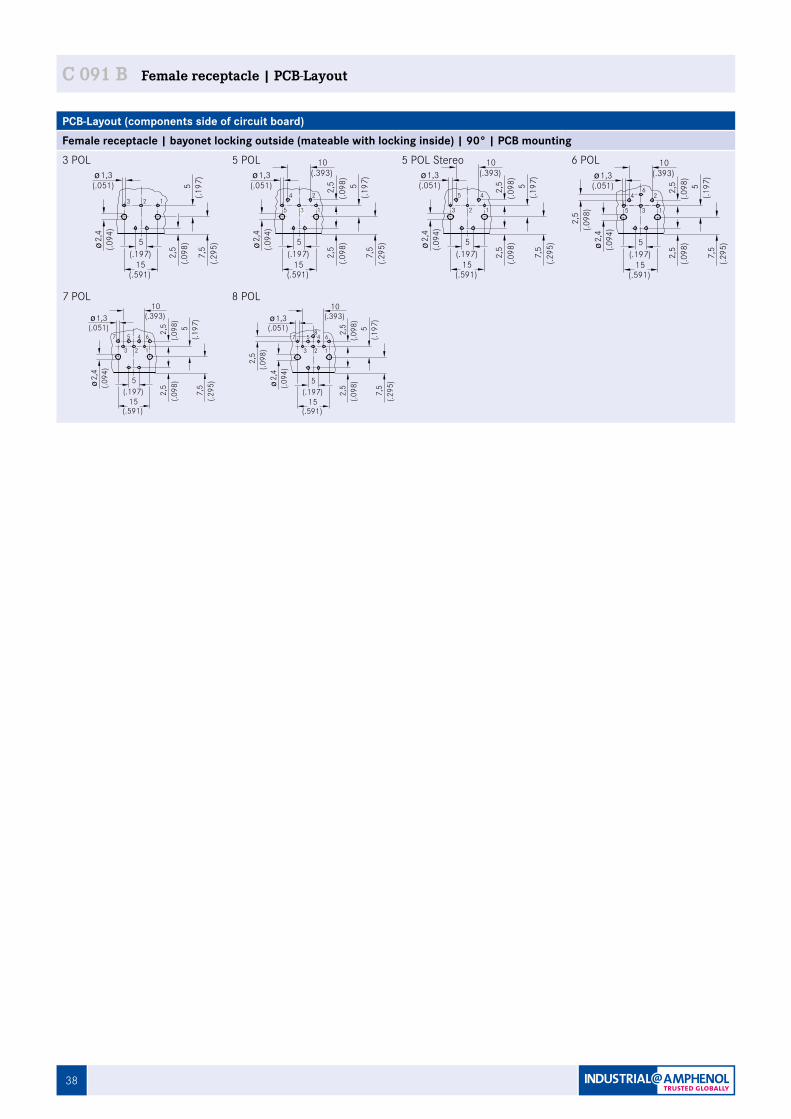
C 091 B Female receptacle | PCB-Layout
PCB-Layout (components side of circuit board)Female receptacle | bayonet locking outside (mateable with locking inside) | 90° | PCB mounting3 POL 5 POL 5 POL Stereo 6 POL
7 POL 8 POL
1,3(.051)
2 1324
3 15
45
2 13
624
3 15
(.098
)
(.098
)
7,5
(.295
) 2,4
2,4
2,4
1,31,3
2,4
15(.591)
(.197)5
Fig. C 091B-83aBohrungsma§e fŸr Leiterplatte
(.094
)
6 Pol.(.393)
10
(.051)
(.094
)
2,5 5
(.197
)
15(.591)
5 Pol.(.0
94)
15(.591)
5(.1
97)
3 Pol.(.393)
10
(.051)
(.094
)
15(.591)
5 Pol. Stereo
(.197)5
(.197)5
(.197)5
2,5
(.098
)
2,5
(.098
)
7,5
(.295
)
2,5 5
(.197
)
2,5
(.098
)
7,5
(.295
)
(.098
)2,
5 5(.1
97)
2,5
(.098
)
7,5
(.295
)
1,3 (.393)10
(.051)
(.098
)2,
5
1,3(.051)
2 1324
3 15
45
2 13
624
3 15
(.098
)
(.098
)
7,5
(.295
) 2,4
2,4
2,4
1,31,3
2,4
15(.591)
(.197)5
Fig. C 091B-83aBohrungsma§e fŸr Leiterplatte
(.094
)
6 Pol.(.393)
10
(.051)
(.094
)
2,5 5
(.197
)
15(.591)
5 Pol.
(.094
)
15(.591)
5(.1
97)
3 Pol.(.393)
10
(.051)
(.094
)
15(.591)
5 Pol. Stereo
(.197)5
(.197)5
(.197)5
2,5
(.098
)
2,5
(.098
)
7,5
(.295
)
2,5 5
(.197
)
2,5
(.098
)
7,5
(.295
)
(.098
)2,
5 5(.1
97)
2,5
(.098
)
7,5
(.295
)
1,3 (.393)10
(.051)
(.098
)2,
5
Fig. C 091B-84aBohrungsma§e fŸr Leiterplatte
1,3(.051)
2 13
7,5
(.295
)2,4
(.094
)
15(.591)
5(.1
97)
3 Pol.
(.197)5
2,5
(.098
)
45
2 13
(.098
)
2,4
1,3 (.393)10
(.051)
(.094
)
2,5 5
(.197
)
15(.591)
5 Pol. Stereo
(.197)5
2,5
(.098
)
7,5
(.295
)
4 657
123
48
657
123
2,4
(.094
)
15(.591)
(.197)5
1,3 (.393)10
(.051)
(.098
)
7 Pol.
2,5 5
(.197
)
2,5
(.098
)
7,5
(.295
)
15(.591)
(.197)5
8 Pol.1,3 (.393)
10
(.051)
2,4
(.094
)
2,5
(.098
)
(.098
)2,
5 5(.1
97)
2,5
(.098
)
7,5
(.295
)

39
C 091 Your Notes

40
C 091
• M16 size• Screw locking according to IEC 61076-2-106• Metal locking ring• Shieldable• 3 - 8, 12 and 14 positions for crimp and solder • IP 69 K / IP 67 / IP 65• Internal strain relief• Male and female cable connectors straight and angled• Male and female receptacles for front and rear panel mounting and PCB mounting• UL registered under file number E 63 093 UL• Connectors are compliant with AISG-standard
C 091 D

41
C 091
General Characteristics Standard CharacteristicsNumber of contacts 3 4 5 5 Stereo 6 7 7 8 12 14View on termination sideof male contact insert
Contact arrangement DIN EN 61076-2-106
03-aü
04-aü
05-aü
05-bü
06-aü
07-aü
07-bü
08-aü
12-aü
14-aü
Contact arrangement IEC 60130-91) ü ü ü ü ü ü
Electrical CharacteristicsRated voltage 2) IEC 60664-1 300 V ≃
(100 V ≃)300 V ≃(63 V ≃)
100 V ≃(32 V ≃)
300 V ≃(63 V ≃)
100 V ≃(32 V ≃)
150 V ≃(32 V ≃)
Rated voltage UL 1977 250 V 60 VRated impulse withstand voltage 2) IEC 60664-1 1500 V
(840 V)1200 V(500 V)
1500 V(840 V)
1200 V(500 V)
Pollution degree 2) IEC 60664-1 1 (3 3))Installation category IEC 60664-1 IInsulation group IEC 60664-1 II, 400 ≤ CTI < 600Current rating IEC 60512-5-2
UL 197710 A / + 40 °C 7 A / + 40 °C 3 A / + 40 °C /
+ 104 °Fplease refer also to current derating curves page 59
Insulation resistance IEC 60512-3-1 > 1010 Ω 4)
Contact resistance IEC 60512-2-1 < 5 m ΩClimatic CharacteristicsClimatic category IEC 60668-1 40 / 100 / 56Temperature range IEC 60668-1 - 40 °C ... + 100 °C / - 40 °F ... + 212 °FSalt Spray Resistance DIN IEC 60068-
2-11, Test Ka 720h
Mechanical CharacteristicsIP-degree IEC 60529 IP 69K / IP 67 / IP 65 (in mated condition)Insertion and withdrawal forces IEC 60512-13-2 25 N
90.oz30 N
110.oz35 N
125.oz50 N
180.oz55 N
200.oz60 N
220.oz50 N
180.ozMechanical operation IEC 60512-9-1 Silver ≥ 500 mating cycles
Gold ≥ 1000 mating cyclesMaterialsHousing material brass or zinc die cast nickel plated or thermoplastDielectric material thermoplasticContact plating silver plated / gold plated 5)
Further CharacteristicsTermination technique solder, crimpWire gauge solder: ≤ 0,5 mm2 / 20 AWG
crimp: 2 - 6 pol (excluding 5S): 0,09 - 1,00 mm2 / 28 - 18 AWGcrimp: 5S, 7, 7S and 8-pol.: 0,09 - 0,75 mm2 / 28 - 20 AWG
solder: ≤ 0,25 mm² / 24 AWG
crimp: 0,09-0,25 mm² / 28 – 24 AWG
Flammability UL 94 V0Locking system IEC 60130-9
DIN EN 61076-2-106
metal screw coupling; tightening torque 1,0 - 1,5 Nm
UL UL 1977 Conditions of acceptability
C 091 D Characteristics
2
2 + 3
31 1
2 3
4
4
4
5
32
1
5 5 Stereo
5
3
4
1
2 4
5
32
16
6
16 7 2
5 34
7
37
21
6
54
7
8
2
8
5
3
4
176
L CD
B
NA
OEF
MK
JH
G
14
L CD
BAEF
MK
JH
G
12
Caution: Do not connect or disconnect under load. Metal housing parts shall be securely incorporated to protected ground.1) Edition 2000-052) Values in brackets are according to DIN EN 61076-2-1063) Designed acc. pollution degree 2; can be used under pollution degree 3 when the rules of IEC 60644-1 are fulfilled4) Under operating conditions >108 Ω5) Remark for gold plated contacts: In order to avoid brittle inter-metallic connections, gold-plated terminals have to be tin-plated in the solder area.
IEC 60 664 = DIN VDE 0110 ; IEC 60 512-x = DIN EN 60 512-x; IEC 60 130-9 = DIN EN 60 130-9; IEC 61076-2-106 = DIN EN 61076-2-106
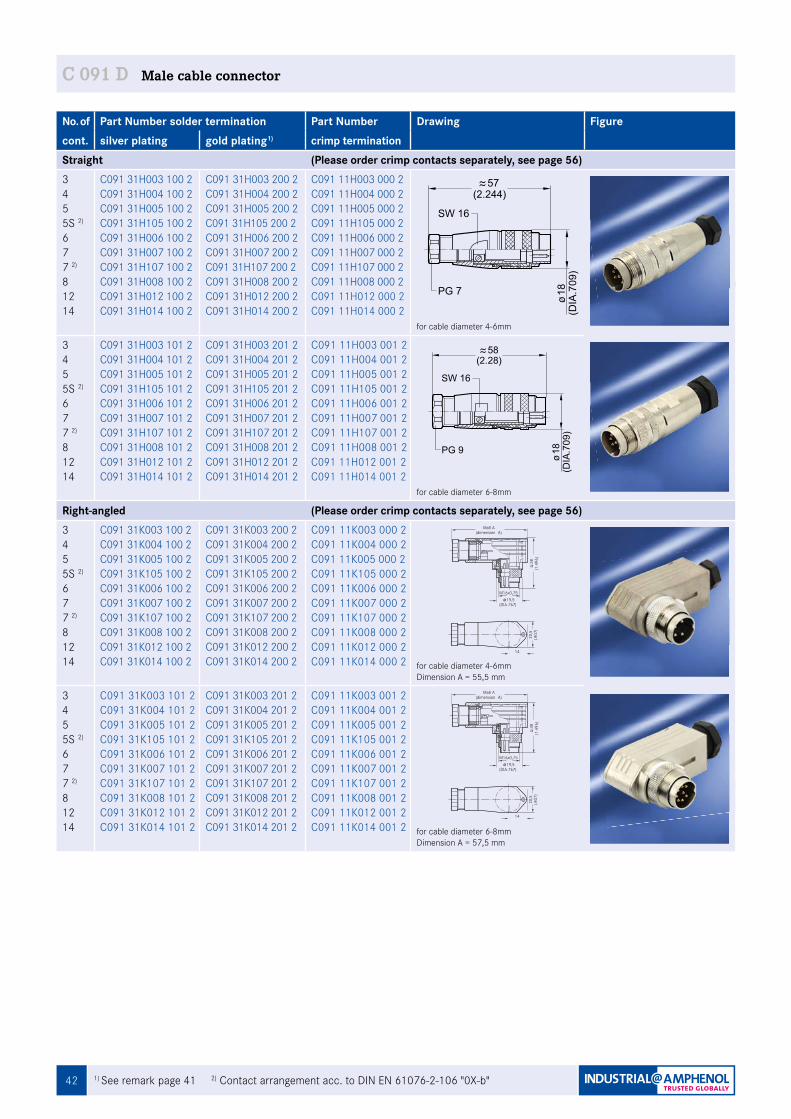
42 1) See remark page 41 2) Contact arrangement acc. to DIN EN 61076-2-106 "0X-b"
C 091 D Male cable connector
No. of Part Number solder termination Part Number Drawing Figurecont. silver plating gold plating1) crimp termination Straight (Please order crimp contacts separately, see page 56)345 5S 2)
677 2)
81214
C091 31H003 100 2C091 31H004 100 2C091 31H005 100 2C091 31H105 100 2C091 31H006 100 2C091 31H007 100 2C091 31H107 100 2C091 31H008 100 2C091 31H012 100 2C091 31H014 100 2
C091 31H003 200 2C091 31H004 200 2C091 31H005 200 2C091 31H105 200 2 C091 31H006 200 2C091 31H007 200 2C091 31H107 200 2 C091 31H008 200 2C091 31H012 200 2C091 31H014 200 2
C091 11H003 000 2C091 11H004 000 2C091 11H005 000 2C091 11H105 000 2C091 11H006 000 2C091 11H007 000 2C091 11H107 000 2C091 11H008 000 2C091 11H012 000 2 C091 11H014 000 2
for cable diameter 4-6mm
345 5S 2)
677 2)
81214
C091 31H003 101 2C091 31H004 101 2C091 31H005 101 2C091 31H105 101 2C091 31H006 101 2C091 31H007 101 2C091 31H107 101 2C091 31H008 101 2C091 31H012 101 2C091 31H014 101 2
C091 31H003 201 2C091 31H004 201 2C091 31H005 201 2C091 31H105 201 2C091 31H006 201 2C091 31H007 201 2C091 31H107 201 2C091 31H008 201 2C091 31H012 201 2C091 31H014 201 2
C091 11H003 001 2C091 11H004 001 2C091 11H005 001 2C091 11H105 001 2C091 11H006 001 2C091 11H007 001 2C091 11H107 001 2C091 11H008 001 2C091 11H012 001 2C091 11H014 001 2
for cable diameter 6-8mm
Right-angled (Please order crimp contacts separately, see page 56)345 5S 2)
677 2)
81214
C091 31K003 100 2C091 31K004 100 2C091 31K005 100 2C091 31K105 100 2C091 31K006 100 2C091 31K007 100 2C091 31K107 100 2C091 31K008 100 2C091 31K012 100 2C091 31K014 100 2
C091 31K003 200 2C091 31K004 200 2C091 31K005 200 2C091 31K105 200 2C091 31K006 200 2C091 31K007 200 2C091 31K107 200 2C091 31K008 200 2C091 31K012 200 2C091 31K014 200 2
C091 11K003 000 2C091 11K004 000 2C091 11K005 000 2C091 11K105 000 2C091 11K006 000 2C091 11K007 000 2C091 11K107 000 2C091 11K008 000 2C091 11K012 000 2C091 11K014 000 2 for cable diameter 4-6mm
Dimension A = 55,5 mm
345 5S 2)
677 2)
81214
C091 31K003 101 2C091 31K004 101 2C091 31K005 101 2C091 31K105 101 2C091 31K006 101 2C091 31K007 101 2C091 31K107 101 2C091 31K008 101 2C091 31K012 101 2C091 31K014 101 2
C091 31K003 201 2C091 31K004 201 2C091 31K005 201 2C091 31K105 201 2C091 31K006 201 2C091 31K007 201 2C091 31K107 201 2C091 31K008 201 2C091 31K012 201 2C091 31K014 201 2
C091 11K003 001 2C091 11K004 001 2C091 11K005 001 2C091 11K105 001 2C091 11K006 001 2C091 11K007 001 2C091 11K107 001 2C091 11K008 001 2C091 11K012 001 2C091 11K014 001 2 for cable diameter 6-8mm
Dimension A = 57,5 mm
(2.244)57
SW 16
18(D
IA.7
09)
PG 7
(2.28)58
SW 16
18(D
IA.7
09)
PG 9
(DIA.767)19,5
M16x0,75
Maß A(dimension A)
38(1
.496
)20
,5(.8
07)
14(.551)
(DIA.767)19,5
M16x0,75
Maß A(dimension A)
38(1
.496
)20
,5(.8
07)
14(.551)
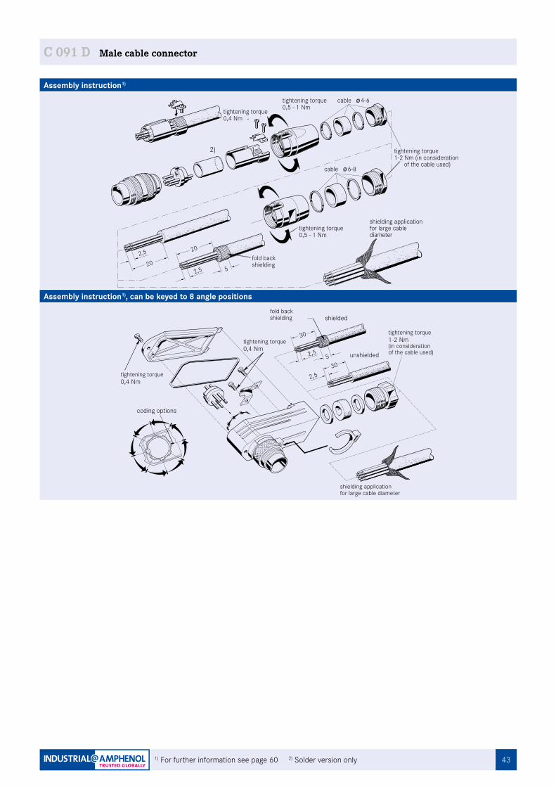
43
Assembly instruction1)
Assembly instruction1), can be keyed to 8 angle positions
50,4 Nmtightening torque
coding options
0,4 Nmtightening torque
C091a_abgew_K_stecker
2,5
2,530
shielded
unshielded
30
fold backshielding
1-2 Nm(in considerationof the cable used)
tightening torque
shielding applicationfor large cable diameter
1) For further information see page 60 2) Solder version only
C 091 D Male cable connector
0,5 - 1 Nm
2,5
202,5
20
tightening torque
Fig_C091D_41a
cable 4-6
cable 6-8
0,5 - 1 Nmtightening torque
fold backshielding
5
1-2 Nm (in consideration of the cable used)
tightening torque
shielding applicationfor large cablediameter
0,4 Nmtightening torque
‘
2)
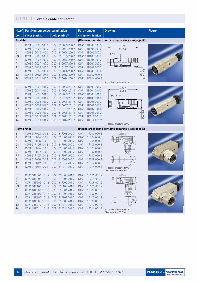
44 1) See remark page 41 2) Contact arrangement acc. to DIN EN 61076-2-106 "0X-b"
C 091 D Female cable connector
No. of Part Number solder termination Part Number Drawing Figurecont. silver plating gold plating1) crimp termination Straight (Please order crimp contacts separately, see page 56)345 5S 2)
677 2)
81214
C091 31D003 100 2C091 31D004 100 2C091 31D005 100 2C091 31D105 100 2C091 31D006 100 2C091 31D007 100 2C091 31D107 100 2C091 31D008 100 2C091 31D012 100 2 C091 31D014 100 2
C091 31D003 200 2C091 31D004 200 2C091 31D005 200 2C091 31D105 200 2C091 31D006 200 2C091 31D007 200 2C091 31D107 200 2C091 31D008 200 2C091 31D012 200 2C091 31D014 200 2
C091 11D003 000 2C091 11D004 000 2C091 11D005 000 2C091 11D105 000 2C091 11D006 000 2C091 11D007 000 2C091 11D107 000 2C091 11D008 000 2C091 11D012 000 2C091 11D014 000 2
for cable diameter 4-6mm
345 5S 2)
677 2)
81214
C091 31D003 101 2C091 31D004 101 2C091 31D005 101 2C091 31D105 101 2C091 31D006 101 2C091 31D007 101 2C091 31D107 101 2C091 31D008 101 2C091 31D012 101 2C091 31D014 101 2
C091 31D003 201 2C091 31D004 201 2C091 31D005 201 2C091 31D105 201 2C091 31D006 201 2C091 31D007 201 2C091 31D107 201 2C091 31D008 201 2C091 31D012 201 2C091 31D014 201 2
C091 11D003 001 2C091 11D004 001 2C091 11D005 001 2C091 11D105 001 2C091 11D006 001 2C091 11D007 001 2C091 11D107 001 2C091 11D008 001 2C091 11D012 001 2 C091 11D014 001 2
for cable diameter 6-8mm
Right-angled (Please order crimp contacts separately, see page 56)345 5S 2)
677 2)
81214
C091 31F003 100 2C091 31F004 100 2C091 31F005 100 2C091 31F105 100 2C091 31F006 100 2C091 31F007 100 2C091 31F107 100 2C091 31F008 100 2C091 31F012 100 2C091 31F014 100 2
C091 31F003 200 2C091 31F004 200 2C091 31F005 200 2C091 31F105 200 2C091 31F006 200 2C091 31F007 200 2C091 31F107 200 2C091 31F008 200 2C091 31F012 200 2C091 31F014 200 2
C091 11F003 000 2C091 11F004 000 2C091 11F005 000 2C091 11F105 000 2C091 11F006 000 2C091 11F007 000 2C091 11F107 000 2C091 11F008 000 2C091 11F012 000 2C091 11F014 000 2 for cable diameter 4-6mm
Dimension A = 55,5 mm
345 5S 2)
677 2)
81214
C091 31F003 101 2C091 31F004 101 2C091 31F005 101 2C091 31F105 101 2C091 31F006 101 2C091 31F007 101 2C091 31F107 101 2C091 31F008 101 2C091 31F012 101 2C091 31F014 101 2
C091 31F003 201 2C091 31F004 201 2C091 31F005 201 2C091 31F105 201 2C091 31F006 201 2C091 31F007 201 2C091 31F107 201 2C091 31F008 201 2C091 31F012 201 2C091 31F014 201 2
C091 11F003 001 2C091 11F004 001 2C091 11F005 001 2C091 11F105 001 2C091 11F006 001 2C091 11F007 001 2C091 11F107 001 2C091 11F008 001 2C091 11F012 001 2C091 11F014 001 2 for cable diameter 6-8mm
Dimension A = 57,5 mm
38(1
.496
)Maß A
(dimension A)
(DIA.767)19,5
M16x0,75
20,5
(.807
)
14(.551)
38(1
.496
)
Maß A(dimension A)
(DIA.767)19,5
M16x0,75
20,5
(.807
)
14(.551)
Fig. C 091D-58a
(2.283)58
SW 16
18(D
IA.7
09)
Fig. C 091D-57a
(2.283)58,3
SW 16
18(D
IA.7
09)
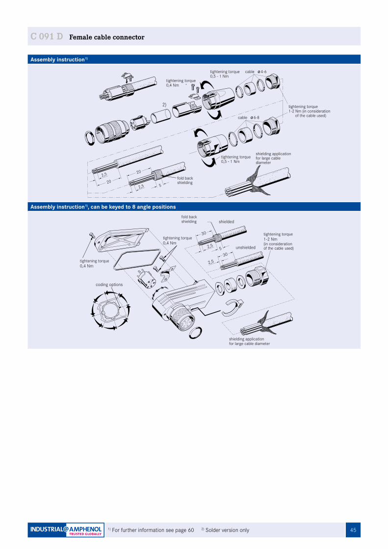
45
Assembly instruction1)
Assembly instruction1), can be keyed to 8 angle positions
1) For further information see page 60 2) Solder version only
C 091 D Female cable connector
2,530
coding options
0,4 Nmtightening torque
0,4 Nmtightening torque
unshielded
C091a_abgew_K_dose
52,5
shielded
30
fold backshielding
tightening torque
shielding applicationfor large cable diameter
1-2 Nm(in considerationof the cable used)
Fig_C091D_42a
cable 4-6
cable 6-8
0,5 - 1 Nmtightening torque
1-2 Nm (in consideration of the cable used)
tightening torque
0,5 - 1 Nmtightening torque
shielding applicationfor large cablediameter
2,5
202,5
20fold backshielding
5
0,4 Nmtightening torque
‘
2)
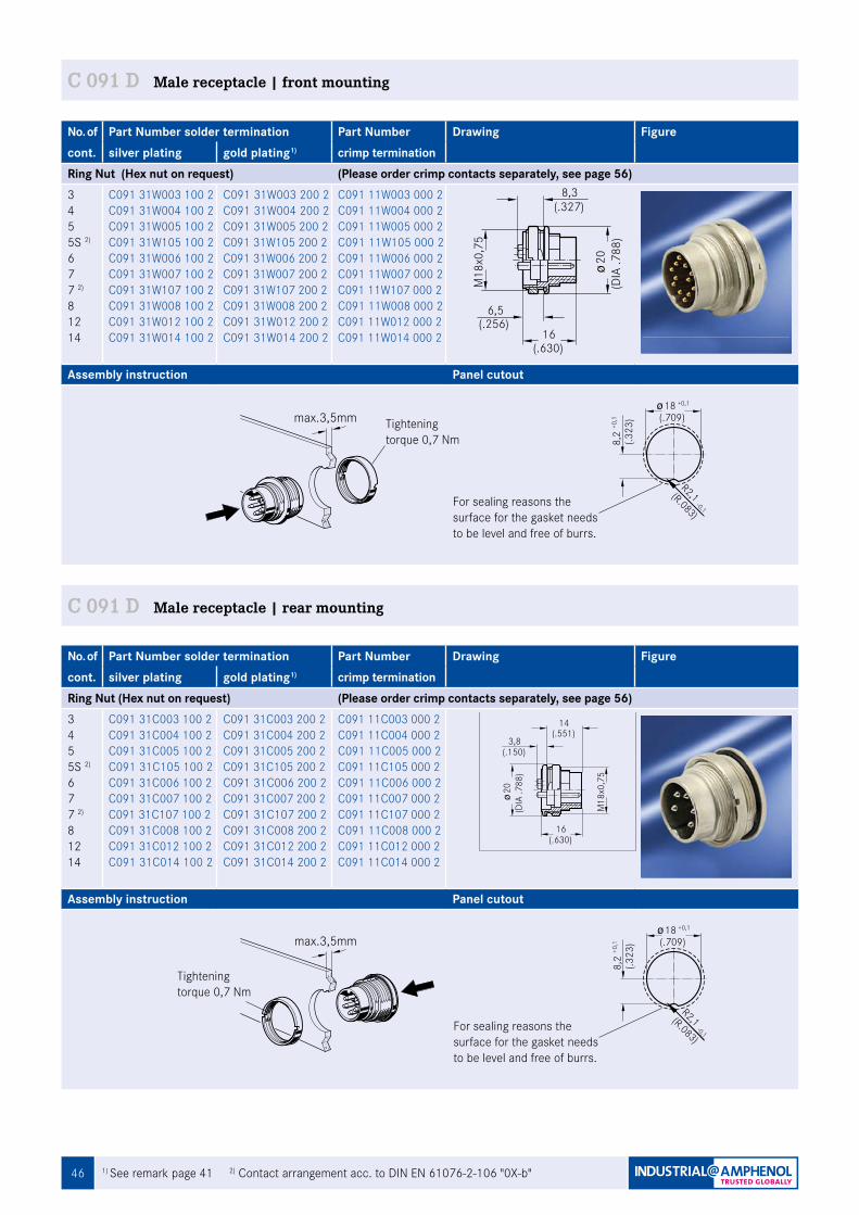
46
No. of Part Number solder termination Part Number Drawing Figurecont. silver plating gold plating1) crimp termination Ring Nut (Hex nut on request) (Please order crimp contacts separately, see page 56)345 5S 2)
677 2)
81214
C091 31W003 100 2C091 31W004 100 2C091 31W005 100 2C091 31W105 100 2C091 31W006 100 2C091 31W007 100 2C091 31W107 100 2C091 31W008 100 2C091 31W012 100 2C091 31W014 100 2
C091 31W003 200 2C091 31W004 200 2C091 31W005 200 2C091 31W105 200 2C091 31W006 200 2C091 31W007 200 2C091 31W107 200 2C091 31W008 200 2C091 31W012 200 2C091 31W014 200 2
C091 11W003 000 2C091 11W004 000 2C091 11W005 000 2C091 11W105 000 2C091 11W006 000 2C091 11W007 000 2C091 11W107 000 2C091 11W008 000 2C091 11W012 000 2C091 11W014 000 2
Assembly instruction Panel cutout
max.3,5mm
Fig. C 091D-117a
Tightening torque 0,7 Nm
For sealing reasons the surface for the gasket needs to be level and free of burrs.
-0,1
R2,1(R.083)
8,2
(.323
)+0
,1
18 +0,1
(.709)
C 091 D Male receptacle | front mounting
1) See remark page 41 2) Contact arrangement acc. to DIN EN 61076-2-106 "0X-b"
(.630)16
6,5
8,3
(.256)
M18
x0,7
5
20(D
IA .7
88)
(.327)
No. of Part Number solder termination Part Number Drawing Figurecont. silver plating gold plating1) crimp termination Ring Nut (Hex nut on request) (Please order crimp contacts separately, see page 56)345 5S 2)
677 2)
81214
C091 31C003 100 2C091 31C004 100 2C091 31C005 100 2C091 31C105 100 2C091 31C006 100 2C091 31C007 100 2C091 31C107 100 2C091 31C008 100 2C091 31C012 100 2C091 31C014 100 2
C091 31C003 200 2C091 31C004 200 2C091 31C005 200 2C091 31C105 200 2C091 31C006 200 2C091 31C007 200 2C091 31C107 200 2C091 31C008 200 2C091 31C012 200 2C091 31C014 200 2
C091 11C003 000 2C091 11C004 000 2C091 11C005 000 2C091 11C105 000 2C091 11C006 000 2C091 11C007 000 2C091 11C107 000 2C091 11C008 000 2C091 11C012 000 2C091 11C014 000 2
Assembly instruction Panel cutout
C 091 D Male receptacle | rear mounting
For sealing reasons the surface for the gasket needs to be level and free of burrs.
-0,1
R2,1(R.083)
8,2
(.323
)+0
,1
18 +0,1
(.709)
3,8
16
20
M18
x0,7
5
Fig. C 091D-96a
(DIA
.788
)
14(.551)
(.150)
(.630)
Tightening torque 0,7 Nm
max.3,5mm
Fig. C 091D-116a
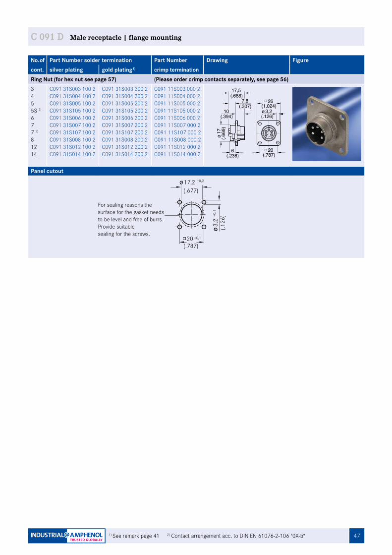
47
No. of Part Number solder termination Part Number Drawing Figurecont. silver plating gold plating1) crimp termination Ring Nut (for hex nut see page 57) (Please order crimp contacts separately, see page 56)345 5S 2)
677 2)
81214
C091 31S003 100 2C091 31S004 100 2C091 31S005 100 2C091 31S105 100 2C091 31S006 100 2C091 31S007 100 2C091 31S107 100 2C091 31S008 100 2C091 31S012 100 2C091 31S014 100 2
C091 31S003 200 2C091 31S004 200 2C091 31S005 200 2C091 31S105 200 2C091 31S006 200 2C091 31S007 200 2C091 31S107 200 2C091 31S008 200 2C091 31S012 200 2C091 31S014 200 2
C091 11S003 000 2C091 11S004 000 2C091 11S005 000 2C091 11S105 000 2C091 11S006 000 2C091 11S007 000 2C091 11S107 000 2C091 11S008 000 2C091 11S012 000 2C091 11S014 000 2
Panel cutout
C 091 D Male receptacle | flange mounting
1) See remark page 41 2) Contact arrangement acc. to DIN EN 61076-2-106 "0X-b"
(.677)17,2
20 ±0,1
(.126
)3,
2+0
,1
(.787)
+0,2
For sealing reasons the surface for the gasket needs to be level and free of burrs.Provide suitable sealing for the screws.
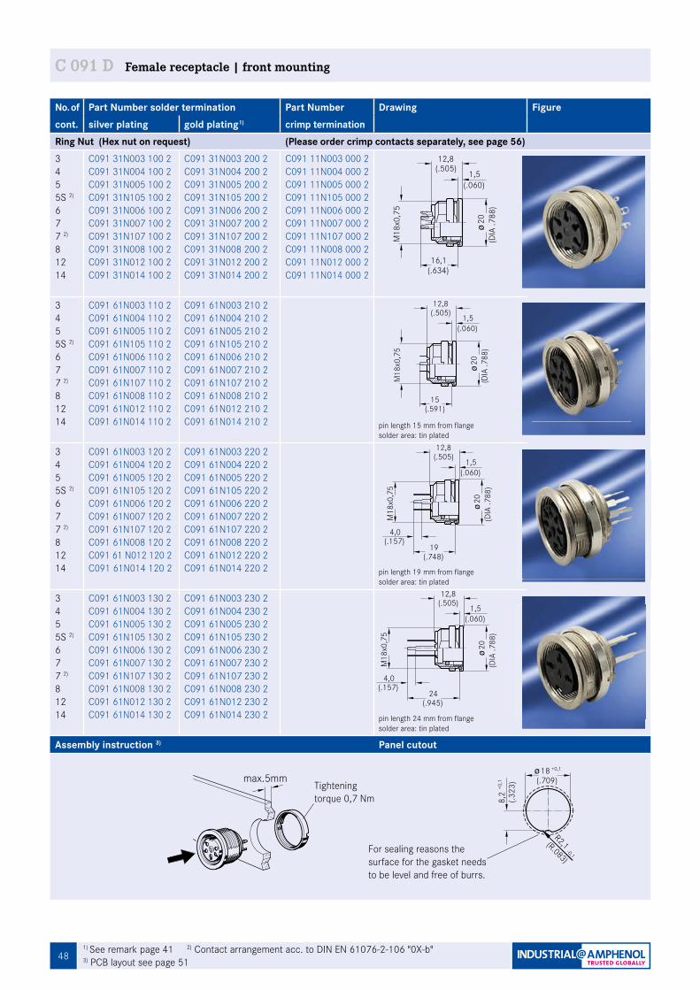
48
No. of Part Number solder termination Part Number Drawing Figurecont. silver plating gold plating1) crimp termination Ring Nut (Hex nut on request) (Please order crimp contacts separately, see page 56)345 5S 2)
677 2)
81214
C091 31N003 100 2C091 31N004 100 2C091 31N005 100 2C091 31N105 100 2C091 31N006 100 2C091 31N007 100 2C091 31N107 100 2C091 31N008 100 2C091 31N012 100 2C091 31N014 100 2
C091 31N003 200 2C091 31N004 200 2C091 31N005 200 2C091 31N105 200 2C091 31N006 200 2C091 31N007 200 2C091 31N107 200 2C091 31N008 200 2C091 31N012 200 2C091 31N014 200 2
C091 11N003 000 2C091 11N004 000 2C091 11N005 000 2C091 11N105 000 2C091 11N006 000 2C091 11N007 000 2C091 11N107 000 2C091 11N008 000 2C091 11N012 000 2C091 11N014 000 2
345 5S 2)
677 2)
81214
C091 61N003 110 2C091 61N004 110 2C091 61N005 110 2C091 61N105 110 2C091 61N006 110 2C091 61N007 110 2C091 61N107 110 2C091 61N008 110 2C091 61N012 110 2C091 61N014 110 2
C091 61N003 210 2C091 61N004 210 2C091 61N005 210 2C091 61N105 210 2C091 61N006 210 2C091 61N007 210 2C091 61N107 210 2C091 61N008 210 2C091 61N012 210 2C091 61N014 210 2 pin length 15 mm from flange
solder area: tin plated
345 5S 2)
677 2)
81214
C091 61N003 120 2 C091 61N004 120 2 C091 61N005 120 2 C091 61N105 120 2 C091 61N006 120 2C091 61N007 120 2 C091 61N107 120 2 C091 61N008 120 2C091 61 N012 120 2C091 61N014 120 2
C091 61N003 220 2C091 61N004 220 2C091 61N005 220 2C091 61N105 220 2C091 61N006 220 2C091 61N007 220 2C091 61N107 220 2C091 61N008 220 2C091 61N012 220 2C091 61N014 220 2 pin length 19 mm from flange
solder area: tin plated
345 5S 2)
677 2)
81214
C091 61N003 130 2C091 61N004 130 2 C091 61N005 130 2 C091 61N105 130 2 C091 61N006 130 2 C091 61N007 130 2 C091 61N107 130 2 C091 61N008 130 2 C091 61N012 130 2C091 61N014 130 2
C091 61N003 230 2C091 61N004 230 2C091 61N005 230 2C091 61N105 230 2C091 61N006 230 2C091 61N007 230 2C091 61N107 230 2C091 61N008 230 2C091 61N012 230 2C091 61N014 230 2 pin length 24 mm from flange
solder area: tin plated
Assembly instruction 3) Panel cutout
max.5mm
Fig. C 091D-114a
C 091 D Female receptacle | front mounting
1) See remark page 41 2) Contact arrangement acc. to DIN EN 61076-2-106 "0X-b" 3) PCB layout see page 51
Tightening torque 0,7 Nm
For sealing reasons the surface for the gasket needs to be level and free of burrs.
-0,1
R2,1(R.083)
8,2
(.323
)+0
,1
18 +0,1
(.709)
12,8(.505)
16,1(.634)
Fig. C 091D-86a
(.060)1,5
M18
x0,7
5
(DIA
.788
)20
M18
x0,7
5
19
4,0
(.748)
Fig. C 091D-88a
(.060)1,5
(.157)
(DIA
.788
)20
12,8(.505)
4,0(.157)
24
(.060)
Fig. C 091D-89a
(.945)
1,5
(DIA
.788
)20
M18
x0,7
5
12,8(.505)
15
Fig. C 091D-87a
(.060)1,5
(.591)M
18x0
,75
(DIA
.788
)20
12,8(.505)
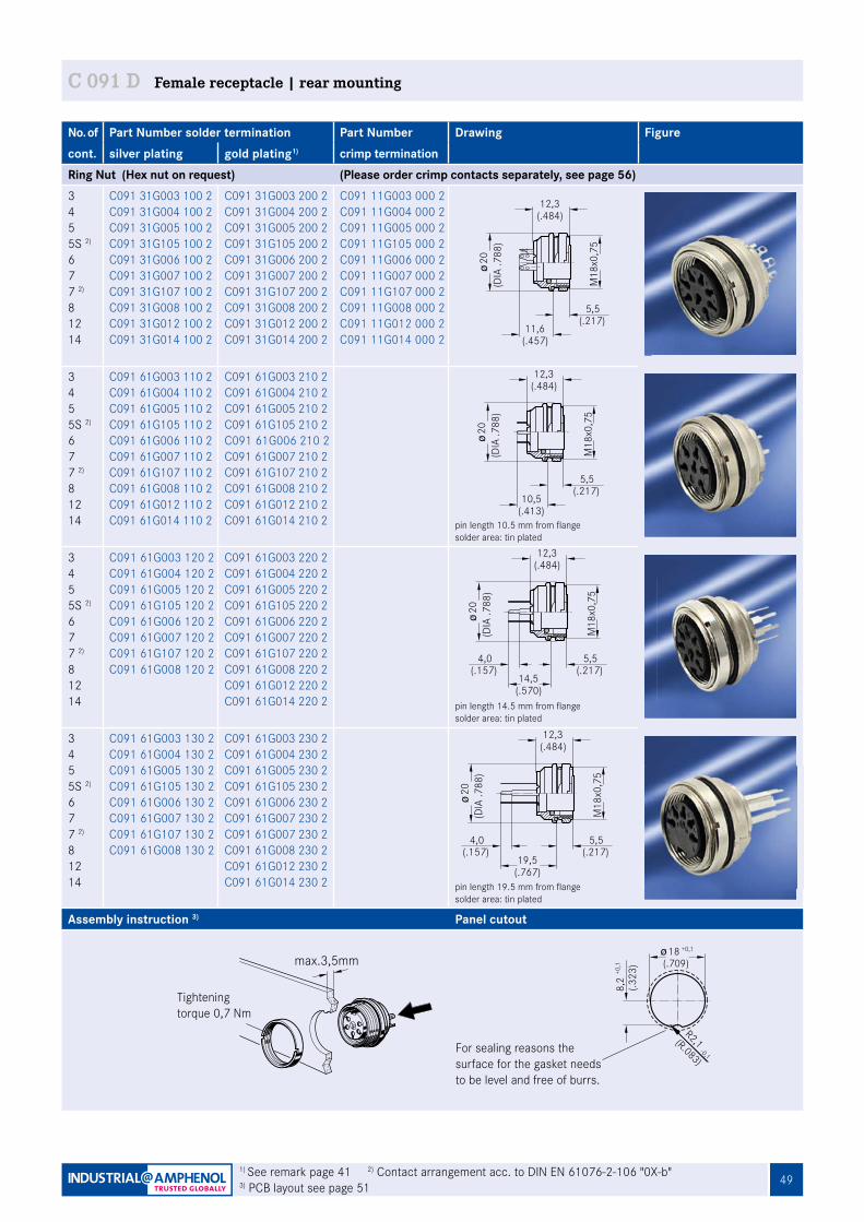
49
No. of Part Number solder termination Part Number Drawing Figurecont. silver plating gold plating1) crimp termination Ring Nut (Hex nut on request) (Please order crimp contacts separately, see page 56)345 5S 2)
677 2)
81214
C091 31G003 100 2C091 31G004 100 2C091 31G005 100 2C091 31G105 100 2C091 31G006 100 2C091 31G007 100 2C091 31G107 100 2C091 31G008 100 2C091 31G012 100 2C091 31G014 100 2
C091 31G003 200 2C091 31G004 200 2C091 31G005 200 2C091 31G105 200 2C091 31G006 200 2C091 31G007 200 2C091 31G107 200 2C091 31G008 200 2C091 31G012 200 2C091 31G014 200 2
C091 11G003 000 2C091 11G004 000 2C091 11G005 000 2C091 11G105 000 2C091 11G006 000 2C091 11G007 000 2C091 11G107 000 2C091 11G008 000 2C091 11G012 000 2C091 11G014 000 2
345 5S 2)
677 2)
81214
C091 61G003 110 2C091 61G004 110 2C091 61G005 110 2C091 61G105 110 2C091 61G006 110 2C091 61G007 110 2C091 61G107 110 2C091 61G008 110 2C091 61G012 110 2C091 61G014 110 2
C091 61G003 210 2C091 61G004 210 2C091 61G005 210 2C091 61G105 210 2C091 61G006 210 2C091 61G007 210 2C091 61G107 210 2C091 61G008 210 2C091 61G012 210 2C091 61G014 210 2 pin length 10.5 mm from flange
solder area: tin plated
345 5S 2)
677 2)
81214
C091 61G003 120 2C091 61G004 120 2C091 61G005 120 2C091 61G105 120 2C091 61G006 120 2C091 61G007 120 2C091 61G107 120 2C091 61G008 120 2
C091 61G003 220 2C091 61G004 220 2C091 61G005 220 2C091 61G105 220 2C091 61G006 220 2C091 61G007 220 2C091 61G107 220 2C091 61G008 220 2C091 61G012 220 2C091 61G014 220 2 pin length 14.5 mm from flange
solder area: tin plated
345 5S 2)
677 2)
81214
C091 61G003 130 2C091 61G004 130 2C091 61G005 130 2C091 61G105 130 2C091 61G006 130 2C091 61G007 130 2C091 61G107 130 2C091 61G008 130 2
C091 61G003 230 2C091 61G004 230 2C091 61G005 230 2C091 61G105 230 2C091 61G006 230 2C091 61G007 230 2C091 61G007 230 2C091 61G008 230 2C091 61G012 230 2C091 61G014 230 2 pin length 19.5 mm from flange
solder area: tin plated
Assembly instruction 3) Panel cutout
max.3,5mm
Fig. C 091D-115a
11,6(.457)
5,5
12,3(.484)
M18
x0,7
5
Fig. C 091D-90a
(.217)
(DIA
.788
)20
10,5(.413)
5,5(.217)
Fig. C 091D-91a
M18
x0,7
5
12,3(.484)
(DIA
.788
)20
C 091 D Female receptacle | rear mounting
1) See remark page 41 2) Contact arrangement acc. to DIN EN 61076-2-106 "0X-b" 3) PCB layout see page 51
For sealing reasons the surface for the gasket needs to be level and free of burrs.
-0,1
R2,1(R.083)
8,2
(.323
)+0
,1
18 +0,1
(.709)
Tightening torque 0,7 Nm
14,5(.570)
4,0 5,5(.217)
Fig. C 091D-92a
M18
x0,7
5
(.157)
12,3(.484)
(DIA
.788
)20
M18
x0,7
5
19,5(.767)
5,5(.217)
4,0(.157)
Fig. C 091D-93a
12,3(.484)
(DIA
.788
)20
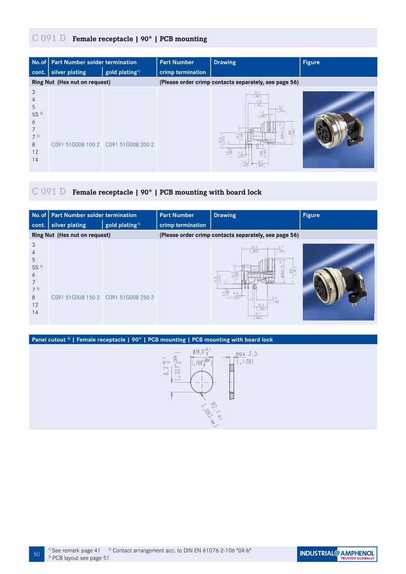
501) See remark page 41 2) Contact arrangement acc. to DIN EN 61076-2-106 "0X-b"3) PCB layout see page 51
No. of Part Number solder termination Part Number Drawing Figurecont. silver plating gold plating1) crimp termination Ring Nut (Hex nut on request) (Please order crimp contacts separately, see page 56)345 5S 2)
677 2)
81214
C091 51G008 100 2 C091 51G008 200 2
No. of Part Number solder termination Part Number Drawing Figurecont. silver plating gold plating1) crimp termination Ring Nut (Hex nut on request) (Please order crimp contacts separately, see page 56)345 5S 2)
677 2)
81214
C091 51G008 150 2 C091 51G008 250 2
C 091 D Female receptacle | 90° | PCB mounting
C 091 D Female receptacle | 90° | PCB mounting with board lock
Panel cutout 3) | Female receptacle | 90° | PCB mounting | PCB mounting with board lock

51
C 091
No. of Part Number solder termination Part Number Drawing Figurecont. silver plating gold plating1) crimp termination Ring Nut (for hex nut see page 5 (Please order crimp contacts separately, see page 56)345 5S 2)
677 2)
81214
C091 31T003 100 2C091 31T004 100 2C091 31T005 100 2C091 31T105 100 2C091 31T006 100 2C091 31T007 100 2C091 31T107 100 2C091 31T008 100 2C091 31T012 100 2C091 31T014 100 2
C091 31T003 200 2C091 31T004 200 2C091 31T005 200 2C091 31T105 200 2C091 31T006 200 2C091 31T007 200 2C091 31T107 200 2C091 31T008 200 2C091 31T012 200 2C091 31T014 200 2
C091 11T003 000 2C091 11T004 000 2C091 11T005 000 2C091 11T105 000 2C091 11T006 000 2C091 11T007 000 2C091 11T107 000 2C091 11T008 000 2C091 11T012 000 2C091 11T014 000 2
Panel cutout
(.677)17,2
20 ±0,1(.1
26)
3,2
+0,1
(.787)
+0,2
C 091 D Female receptacle | flange mounting
For sealing reasons the surface for the gasket needs to be level and free of burrs.Provide suitable sealing for the screws.
C 091 D Female receptacle | PCB-Layout
PCB-Layout (components side of circuit board)Female receptacle | front mounting | rear mounting3 POL 4 POL 5 POL 5 POL S1)
6 POL 7 POL 7 POL1) 8 POL
12 POL 14 POL
Female receptacle | 90° | PCB mounting PCB mounting with board lock8 POL 8 POL
1
1
4,26
6,47
6,06
3,5
7,0
4,95
5
6,06
3,5
3,5
0,7
3,5
3,5
3,53,
53,
53,
5
4,95
4
3
2
13
2
4
33
2
15
4
42
1
53
2
15
46
3 45
61
2
7
5 2
167
3
24
67
38
F
HJ M
K EA
L D
B C
G
HJ M F
K N OE
A L D
B C
G37
30
4,5
5 Pol. Stereo
4 Pol.
12 Pol.
DIN 45 3226 Pol.
DIN 45 3225 Pol.
DIN 41 5243 Pol.
DIN 45 3297 Pol.
DIN 41 5247 Pol.
DIN 45 3268 Pol.
9,03,0
0,8
6,0
5,0
8,0
3,5
14 Pol.
1,1
1,1
1,1
1,1
2,48
1,1
1,1
4,95
1,34
2,78 1,
11,
1
3,09,0
5,0
8,0
3,5
3730
0,8
6,0
4,95
7,0
7,04,95
7,0
6,067,0
1
1
4,26
6,47
6,06
3,5
7,0
4,95
5
6,06
3,5
3,5
0,7
3,5
3,5
3,53,
53,
53,
5
4,95
4
3
2
13
2
4
33
2
15
4
42
1
53
2
15
46
3 45
61
2
7
5 2
167
3
24
67
38
F
HJ M
K EA
L D
B C
G
HJ M F
K N OE
A L D
B C
G
3730
4,5
5 Pol. Stereo
4 Pol.
12 Pol.
DIN 45 3226 Pol.
DIN 45 3225 Pol.
DIN 41 5243 Pol.
DIN 45 3297 Pol.
DIN 41 5247 Pol.
DIN 45 3268 Pol.
9,03,0
0,8
6,0
5,0
8,0
3,5
14 Pol.
1,1
1,1
1,1
1,1
2,48
1,1
1,1
4,95
1,34
2,78 1,
11,
1
3,09,0
5,0
8,0
3,5
3730
0,8
6,0
4,95
7,0
7,04,95
7,0
6,067,0
3
4
4,26
6,47
6,06
3,5
7,0
4,95
4
6,06
3,5
3,5
0,7
3,5
3,5
3,53,
53,
53,
5
4,95
5
1
2
31
3
1
23
4
51
2
52
3
43
4
51
26
4 32
16
5
7
4 2
376
1
25
76
18
Fig. C 091A-78a
5 Pol. Stereo
4 Pol.
12 Pol.
DIN 45 3226 Pol.
DIN 45 3225 Pol.
DIN 41 5243 Pol.
DIN 45 3297 Pol.
DIN 41 5247 Pol.
DIN 45 3268 Pol.
14 Pol.
1,1
1,1
1,1
1,1
2,48
1,1
1,1
4,95
1,34
2,78 1,
11,
1
4,95
7,0
7,04,95
7,0
6,067,0
contact arrangement acc. to IEC 60 130-9
5,08,0
3730
3,5
3,09,0
6,0
0,8
B C
A L
KJ H
M
G
FE
D
3730
4,6,0
5,0
9,03,0
3,5
0,8
8,0
BC
LA
KJ H
G
MN
FE
DO
3
4
4,26
6,47
6,06
3,5
7,0
4,95
4
6,06
3,5
3,5
0,7
3,5
3,5
3,53,
53,
53,
5
4,95
5
1
2
31
3
1
23
4
51
2
52
3
43
4
51
26
4 32
16
5
7
4 2
376
1
25
76
18
Fig. C 091A-78a
5 Pol. Stereo
4 Pol.
12 Pol.
DIN 45 3226 Pol.
DIN 45 3225 Pol.
DIN 41 5243 Pol.
DIN 45 3297 Pol.
DIN 41 5247 Pol.
DIN 45 3268 Pol.
14 Pol.
1,1
1,1
1,1
1,1
2,48
1,1
1,1
4,95
1,34
2,78 1,
11,
1
4,95
7,0
7,04,95
7,0
6,067,0
contact arrangement acc. to IEC 60 130-9
5,08,0
3730
3,5
3,09,0
6,0
0,8
B C
A L
KJ H
M
G
FE
D
3730
4,6,0
5,0
9,03,0
3,5
0,8
8,0
BC
LA
KJ H
G
MN
FE
DO
1
1
4,26
6,47
6,06
3,5
7,0
4,95
5
6,06
3,5
3,5
0,7
3,5
3,5
3,53,
53,
53,
5
4,95
4
3
2
13
2
4
33
2
15
4
42
1
53
2
15
46
3 45
61
2
7
5 2
167
3
24
67
38
F
HJ M
K EA
L D
B C
G
HJ M F
K N OE
A L D
B C
G
3730
4,5
5 Pol. Stereo
4 Pol.
12 Pol.
DIN 45 3226 Pol.
DIN 45 3225 Pol.
DIN 41 5243 Pol.
DIN 45 3297 Pol.
DIN 41 5247 Pol.
DIN 45 3268 Pol.
9,03,0
0,8
6,0
5,0
8,0
3,5
14 Pol.
1,1
1,1
1,1
1,1
2,48
1,1
1,1
4,95
1,34
2,78 1,
11,
1
3,09,0
5,0
8,0
3,5
3730
0,8
6,0
4,95
7,0
7,04,95
7,0
6,067,0
3
4
4,26
6,47
6,06
3,5
7,0
4,95
4
6,06
3,5
3,5
0,7
3,5
3,5
3,53,
53,
53,
5
4,95
5
1
2
31
3
1
23
4
51
2
52
3
43
4
51
26
4 32
16
5
7
4 2
376
1
25
76
18
Fig. C 091A-78a
5 Pol. Stereo
4 Pol.
12 Pol.
DIN 45 3226 Pol.
DIN 45 3225 Pol.
DIN 41 5243 Pol.
DIN 45 3297 Pol.
DIN 41 5247 Pol.
DIN 45 3268 Pol.
14 Pol.
1,1
1,1
1,1
1,1
2,48
1,1
1,1
4,95
1,34
2,78 1,
11,
1
4,95
7,0
7,04,95
7,0
6,067,0
contact arrangement acc. to IEC 60 130-9
5,08,0
3730
3,5
3,09,0
6,0
0,8
B C
A L
KJ H
M
G
FE
D
3730
4,6,0
5,0
9,03,0
3,5
0,8
8,0
BC
LA
KJ H
G
MN
FE
DO
3
4
4,26
6,47
6,06
3,5
7,0
4,95
4
6,06
3,5
3,5
0,7
3,5
3,5
3,53,
53,
53,
5
4,95
5
1
2
31
3
1
23
4
51
2
52
3
43
4
51
26
4 32
16
5
7
4 2
376
1
25
76
18
Fig. C 091A-78a
5 Pol. Stereo
4 Pol.
12 Pol.
DIN 45 3226 Pol.
DIN 45 3225 Pol.
DIN 41 5243 Pol.
DIN 45 3297 Pol.
DIN 41 5247 Pol.
DIN 45 3268 Pol.
14 Pol.
1,1
1,1
1,1
1,1
2,48
1,1
1,1
4,95
1,34
2,78 1,
11,
1
4,95
7,0
7,04,95
7,0
6,067,0
contact arrangement acc. to IEC 60 130-9
5,08,0
3730
3,5
3,09,0
6,0
0,8
B C
A L
KJ H
M
G
FE
D
3730
4,6,0
5,0
9,03,0
3,5
0,8
8,0
BC
LA
KJ H
G
MN
FE
DO
3
4
4,26
6,47
6,06
3,5
7,0
4,95
4
6,06
3,5
3,5
0,7
3,5
3,5
3,53,
53,
53,
5
4,95
5
1
2
31
3
1
23
4
51
2
52
3
43
4
51
26
4 32
16
5
7
4 2
376
1
25
76
18
Fig. C 091A-78a
5 Pol. Stereo
4 Pol.
12 Pol.
DIN 45 3226 Pol.
DIN 45 3225 Pol.
DIN 41 5243 Pol.
DIN 45 3297 Pol.
DIN 41 5247 Pol.
DIN 45 3268 Pol.
14 Pol.
1,1
1,1
1,1
1,1
2,48
1,1
1,1
4,95
1,34
2,78 1,
11,
1
4,95
7,0
7,04,95
7,0
6,067,0
contact arrangement acc. to IEC 60 130-9
5,08,0
3730
3,5
3,09,0
6,0
0,8
B C
A L
KJ H
M
G
FE
D
3730
4,6,0
5,0
9,03,0
3,5
0,8
8,0
BC
LA
KJ H
G
MN
FE
DO
1
1
4,26
6,47
6,06
3,5
7,0
4,95
5
6,06
3,5
3,5
0,7
3,5
3,5
3,53,
53,
53,
5
4,95
4
3
2
13
2
4
33
2
15
4
42
1
53
2
15
46
3 45
61
2
7
5 2
167
3
24
67
38
F
HJ M
K EA
L D
B C
G
HJ M F
K N OE
A L D
B C
G
3730
4,5
5 Pol. Stereo
4 Pol.
12 Pol.
DIN 45 3226 Pol.
DIN 45 3225 Pol.
DIN 41 5243 Pol.
DIN 45 3297 Pol.
DIN 41 5247 Pol.
DIN 45 3268 Pol.
9,03,0
0,8
6,0
5,0
8,0
3,5
14 Pol.
1,1
1,1
1,1
1,1
2,48
1,1
1,1
4,95
1,34
2,78
1,1
1,1
3,09,0
5,0
8,0
3,5
3730
0,8
6,0
4,95
7,0
7,04,95
7,0
6,067,0
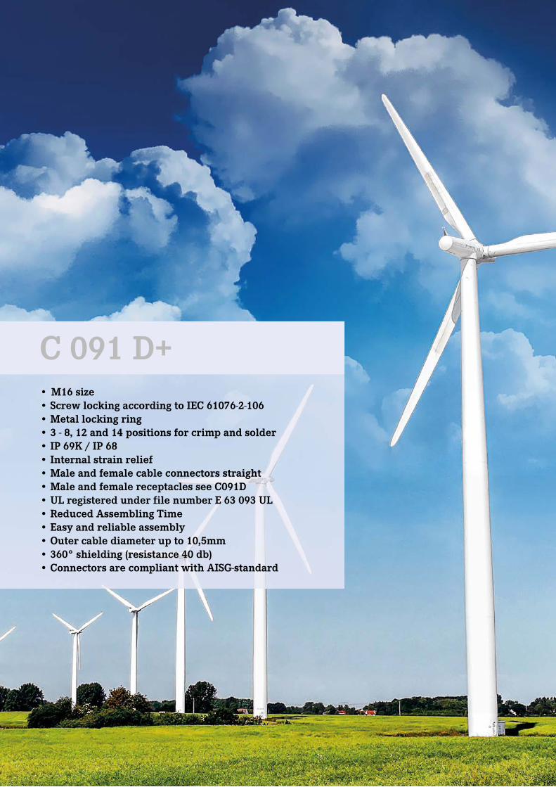
52
C 091
• M16 size• Screw locking according to IEC 61076-2-106• Metal locking ring• 3 - 8, 12 and 14 positions for crimp and solder • IP 69K / IP 68• Internal strain relief• Male and female cable connectors straight• Male and female receptacles see C091D • UL registered under file number E 63 093 UL• Reduced Assembling Time • Easy and reliable assembly • Outer cable diameter up to 10,5mm • 360° shielding (resistance 40 db) • Connectors are compliant with AISG-standard
C 091 D+
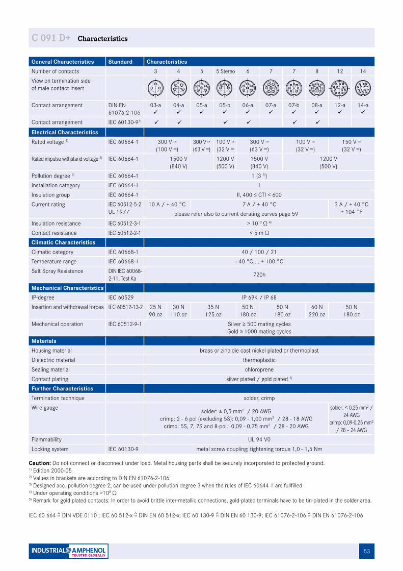
53
C 091
General Characteristics Standard CharacteristicsNumber of contacts 3 4 5 5 Stereo 6 7 7 8 12 14View on termination sideof male contact insert
Contact arrangement DIN EN 61076-2-106
03-aü
04-aü
05-aü
05-bü
06-aü
07-aü
07-bü
08-aü
12-aü
14-aü
Contact arrangement IEC 60130-91) ü ü ü ü ü ü
Electrical CharacteristicsRated voltage 2) IEC 60664-1 300 V ≃
(100 V ≃)300 V ≃(63 V ≃)
100 V ≃(32 V ≃
300 V ≃(63 V ≃)
100 V ≃(32 V ≃)
150 V ≃(32 V ≃)
Rated impulse withstand voltage 2) IEC 60664-1 1500 V(840 V)
1200 V(500 V)
1500 V(840 V)
1200 V(500 V)
Pollution degree 2) IEC 60664-1 1 (3 3))Installation category IEC 60664-1 IInsulation group IEC 60664-1 II, 400 ≤ CTI < 600Current rating IEC 60512-5-2
UL 197710 A / + 40 °C 7 A / + 40 °C 3 A / + 40 °C
+ 104 °Fplease refer also to current derating curves page 59Insulation resistance IEC 60512-3-1 > 1010 Ω 4)
Contact resistance IEC 60512-2-1 < 5 m ΩClimatic CharacteristicsClimatic category IEC 60668-1 40 / 100 / 21Temperature range IEC 60668-1 - 40 °C ... + 100 °CSalt Spray Resistance DIN IEC 60068-
2-11, Test Ka 720h
Mechanical CharacteristicsIP-degree IEC 60529 IP 69K / IP 68Insertion and withdrawal forces IEC 60512-13-2 25 N
90.oz30 N
110.oz35 N
125.oz50 N
180.oz50 N
180.oz60 N
220.oz50 N
180.ozMechanical operation IEC 60512-9-1 Silver ≥ 500 mating cycles
Gold ≥ 1000 mating cyclesMaterialsHousing material brass or zinc die cast nickel plated or thermoplastDielectric material thermoplasticSealing material chloropreneContact plating silver plated / gold plated 5)
Further CharacteristicsTermination technique solder, crimpWire gauge solder: ≤ 0,5 mm2 / 20 AWG
crimp: 2 - 6 pol (excluding 5S): 0,09 - 1,00 mm2 / 28 - 18 AWGcrimp: 5S, 7, 7S and 8-pol.: 0,09 - 0,75 mm2 / 28 - 20 AWG
solder: ≤ 0,25 mm² / 24 AWG
crimp: 0,09-0,25 mm² / 28 – 24 AWG
Flammability UL 94 V0Locking system IEC 60130-9 metal screw coupling; tightening torque 1,0 - 1,5 Nm
C 091 D+ Characteristics
2
2 + 3
31 1
2 3
4
4
4
5
32
1
5 5 Stereo
5
3
4
1
2 4
5
32
16
6
16 7 2
5 34
7
37
21
6
54
7
8
2
8
5
3
4
176
L CD
B
NA
OEF
MK
JH
G
14
L CD
BAEF
MK
JH
G
12
Caution: Do not connect or disconnect under load. Metal housing parts shall be securely incorporated to protected ground.1) Edition 2000-052) Values in brackets are according to DIN EN 61076-2-1063) Designed acc. pollution degree 2; can be used under pollution degree 3 when the rules of IEC 60644-1 are fullfilled4) Under operating conditions >108 Ω 5) Remark for gold plated contacts: In order to avoid brittle inter-metallic connections, gold-plated terminals have to be tin-plated in the solder area.
IEC 60 664 = DIN VDE 0110 ; IEC 60 512-x = DIN EN 60 512-x; IEC 60 130-9 = DIN EN 60 130-9; IEC 61076-2-106 = DIN EN 61076-2-106
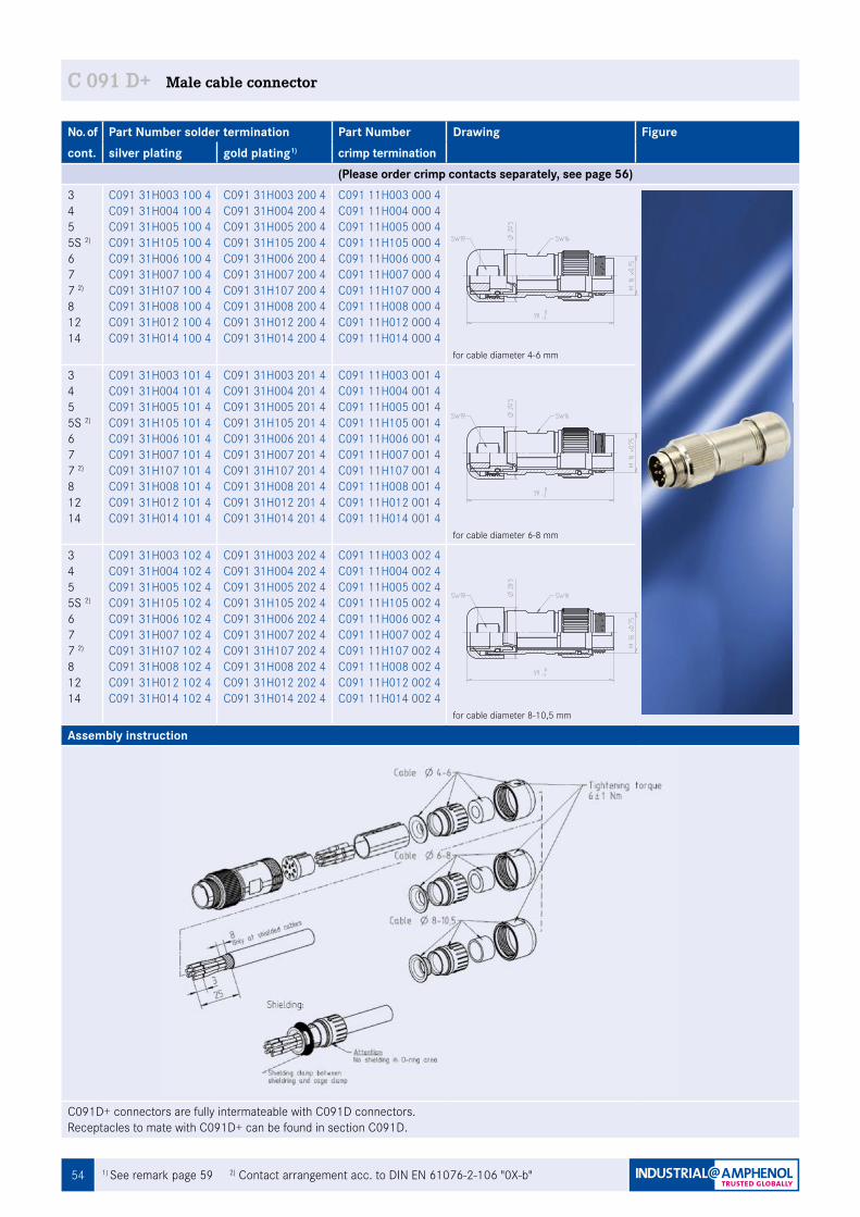
54
C 091
1) See remark page 59 2) Contact arrangement acc. to DIN EN 61076-2-106 "0X-b"
No. of Part Number solder termination Part Number Drawing Figurecont. silver plating gold plating1) crimp termination
(Please order crimp contacts separately, see page 56)345 5S 2)
677 2)
81214
C091 31H003 100 4C091 31H004 100 4C091 31H005 100 4C091 31H105 100 4C091 31H006 100 4C091 31H007 100 4C091 31H107 100 4C091 31H008 100 4C091 31H012 100 4C091 31H014 100 4
C091 31H003 200 4C091 31H004 200 4C091 31H005 200 4C091 31H105 200 4C091 31H006 200 4C091 31H007 200 4C091 31H107 200 4C091 31H008 200 4C091 31H012 200 4C091 31H014 200 4
C091 11H003 000 4C091 11H004 000 4C091 11H005 000 4C091 11H105 000 4C091 11H006 000 4C091 11H007 000 4C091 11H107 000 4C091 11H008 000 4C091 11H012 000 4C091 11H014 000 4
for cable diameter 4-6 mm
345 5S 2)
677 2)
81214
C091 31H003 101 4C091 31H004 101 4C091 31H005 101 4C091 31H105 101 4C091 31H006 101 4C091 31H007 101 4C091 31H107 101 4C091 31H008 101 4C091 31H012 101 4C091 31H014 101 4
C091 31H003 201 4C091 31H004 201 4C091 31H005 201 4C091 31H105 201 4C091 31H006 201 4C091 31H007 201 4C091 31H107 201 4C091 31H008 201 4C091 31H012 201 4C091 31H014 201 4
C091 11H003 001 4C091 11H004 001 4C091 11H005 001 4C091 11H105 001 4C091 11H006 001 4C091 11H007 001 4C091 11H107 001 4C091 11H008 001 4C091 11H012 001 4C091 11H014 001 4
for cable diameter 6-8 mm
345 5S 2)
677 2)
81214
C091 31H003 102 4C091 31H004 102 4C091 31H005 102 4C091 31H105 102 4C091 31H006 102 4C091 31H007 102 4C091 31H107 102 4C091 31H008 102 4C091 31H012 102 4C091 31H014 102 4
C091 31H003 202 4C091 31H004 202 4C091 31H005 202 4C091 31H105 202 4C091 31H006 202 4C091 31H007 202 4C091 31H107 202 4C091 31H008 202 4C091 31H012 202 4C091 31H014 202 4
C091 11H003 002 4C091 11H004 002 4C091 11H005 002 4C091 11H105 002 4C091 11H006 002 4C091 11H007 002 4C091 11H107 002 4C091 11H008 002 4C091 11H012 002 4C091 11H014 002 4
for cable diameter 8-10,5 mm
Assembly instruction
C091D+ connectors are fully intermateable with C091D connectors.Receptacles to mate with C091D+ can be found in section C091D.
C 091 D+ Male cable connector
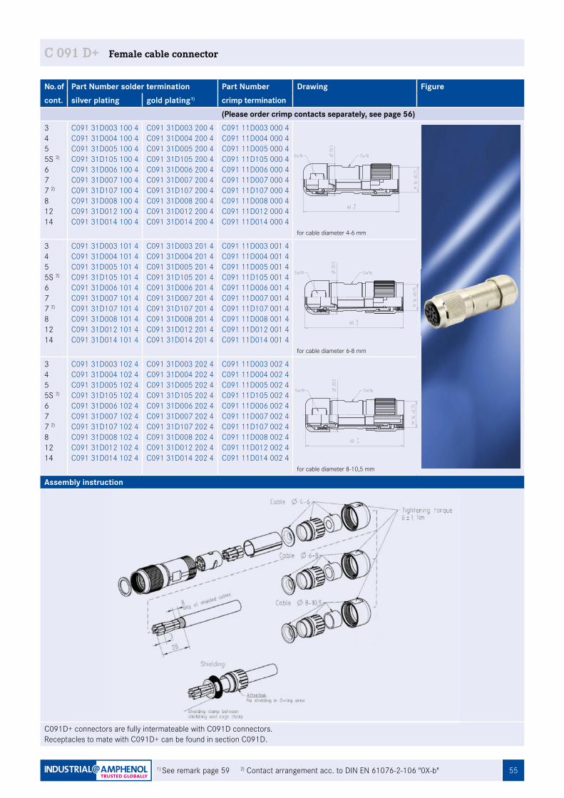
55
C 091
1) See remark page 59 2) Contact arrangement acc. to DIN EN 61076-2-106 "0X-b"
No. of Part Number solder termination Part Number Drawing Figurecont. silver plating gold plating1) crimp termination
(Please order crimp contacts separately, see page 56)345 5S 2)
677 2)
81214
C091 31D003 100 4C091 31D004 100 4 C091 31D005 100 4 C091 31D105 100 4 C091 31D006 100 4 C091 31D007 100 4 C091 31D107 100 4 C091 31D008 100 4 C091 31D012 100 4 C091 31D014 100 4
C091 31D003 200 4 C091 31D004 200 4 C091 31D005 200 4 C091 31D105 200 4 C091 31D006 200 4 C091 31D007 200 4 C091 31D107 200 4 C091 31D008 200 4 C091 31D012 200 4 C091 31D014 200 4
C091 11D003 000 4 C091 11D004 000 4 C091 11D005 000 4 C091 11D105 000 4 C091 11D006 000 4 C091 11D007 000 4 C091 11D107 000 4 C091 11D008 000 4C091 11D012 000 4 C091 11D014 000 4
for cable diameter 4-6 mm
345 5S 2)
677 2)
81214
C091 31D003 101 4 C091 31D004 101 4 C091 31D005 101 4 C091 31D105 101 4 C091 31D006 101 4 C091 31D007 101 4 C091 31D107 101 4 C091 31D008 101 4 C091 31D012 101 4 C091 31D014 101 4
C091 31D003 201 4 C091 31D004 201 4 C091 31D005 201 4 C091 31D105 201 4 C091 31D006 201 4 C091 31D007 201 4 C091 31D107 201 4 C091 31D008 201 4 C091 31D012 201 4 C091 31D014 201 4
C091 11D003 001 4 C091 11D004 001 4 C091 11D005 001 4 C091 11D105 001 4 C091 11D006 001 4 C091 11D007 001 4 C091 11D107 001 4 C091 11D008 001 4 C091 11D012 001 4 C091 11D014 001 4
for cable diameter 6-8 mm
345 5S 2)
677 2)
81214
C091 31D003 102 4 C091 31D004 102 4 C091 31D005 102 4 C091 31D105 102 4 C091 31D006 102 4 C091 31D007 102 4 C091 31D107 102 4 C091 31D008 102 4 C091 31D012 102 4 C091 31D014 102 4
C091 31D003 202 4 C091 31D004 202 4 C091 31D005 202 4 C091 31D105 202 4 C091 31D006 202 4 C091 31D007 202 4 C091 31D107 202 4 C091 31D008 202 4 C091 31D012 202 4 C091 31D014 202 4
C091 11D003 002 4 C091 11D004 002 4 C091 11D005 002 4 C091 11D105 002 4 C091 11D006 002 4 C091 11D007 002 4 C091 11D107 002 4 C091 11D008 002 4 C091 11D012 002 4 C091 11D014 002 4
for cable diameter 8-10,5 mm
Assembly instruction
C091D+ connectors are fully intermateable with C091D connectors.Receptacles to mate with C091D+ can be found in section C091D.
C 091 D+ Female cable connector
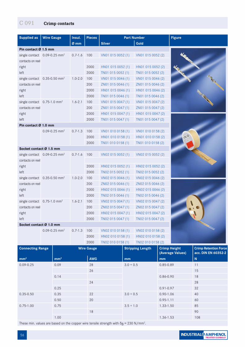
56
Supplied as Wire Gauge Insul. Pieces Part Number FigureØ mm Silver Gold
Pin contact Ø 1.5 mmsingle contact 0.09-0.25 mm2 0.7-1.6 100 VN01 015 0052 (1) VN01 015 0052 (2)contacts on reelright 2000 HN01 015 0052 (1) HN01 015 0052 (2)left 2000 TN01 015 0052 (1) TN01 015 0052 (2)single contact 0.35-0.50 mm2 1.0-2.0 100 VN01 015 0046 (1) VN01 015 0046 (2)contacts on reel 200 ZN01 015 0046 (1) ZN01 015 0046 (2)right 2000 HN01 015 0046 (1) HN01 015 0046 (2)left 2000 TN01 015 0046 (1) TN01 015 0046 (2)single contact 0.75-1.0 mm2 1.6-2.1 100 VN01 015 0047 (1) VN01 015 0047 (2)contacts on reel 200 ZN01 015 0047 (1) ZN01 015 0047 (2)right 2000 HN01 015 0047 (1) HN01 015 0047 (2)left 2000 TN01 015 0047 (1) TN01 015 0047 (2)Pin contact Ø 1.0 mm
0.09-0.25 mm2 0.7-1.3 100 VN01 010 0158 (1) VN01 010 0158 (2) 2000 HN01 010 0158 (1) HN01 010 0158 (2) 2000 TN01 010 0158 (1) TN01 010 0158 (2)
Socket contact Ø 1.5 mmsingle contact 0.09-0.25 mm2 0.7-1.6 100 VN02 015 0052 (1) VN02 015 0052 (2)contacts on reelright 2000 HN02 015 0052 (1) HN02 015 0052 (2)left 2000 TN02 015 0052 (1) TN02 015 0052 (2)single contact 0.35-0.50 mm2 1.0-2.0 100 VN02 015 0046 (1) VN02 015 0046 (2)contacts on reel 200 ZN02 015 0046 (1) ZN02 015 0046 (2)right 2000 HN02 015 0046 (1) HN02 015 0046 (2)left 2000 TN02 015 0046 (1) TN02 015 0046 (2)single contact 0.75-1.0 mm2 1.6-2.1 100 VN02 015 0047 (1) VN02 015 0047 (2)contacts on reel 200 ZN02 015 0047 (1) ZN02 015 0047 (2)right 2000 HN02 015 0047 (1) HN02 015 0047 (2)left 2000 TN02 015 0047 (1) TN02 015 0047 (2)Socket contact Ø 1.0 mm
0.09-0.25 mm2 0.7-1.3 100 VN02 010 0158 (1) VN02 010 0158 (2) 2000 HN02 010 0158 (1) HN02 010 0158 (2) 2000 TN02 010 0158 (1) TN02 010 0158 (2)
C 091 Crimp contacts
Connecting Range Wire Gauge Stripping Length Crimp Height(Average Values)
Crimp Retention Force acc. DIN EN 60352-2
mm2 mm2 AWG mm mm N0.09-0.25 0.09 28 3.0 + 0.5 0.85-0.89 11
26 150.14 0.86-0.90 18
24 280.25 0.91-0.97 32
0.35-0.50 0.35 22 3.0 + 0.5 0.90-1.06 400.50 20 0.95-1.11 60
0.75-1.00 0.75 3.5 + 1.0 1.33-1.50 8518 90
1.00 1.36-1.53 108These min. values are based on the copper wire tensile strength with δB ≈ 230 N/mm2.
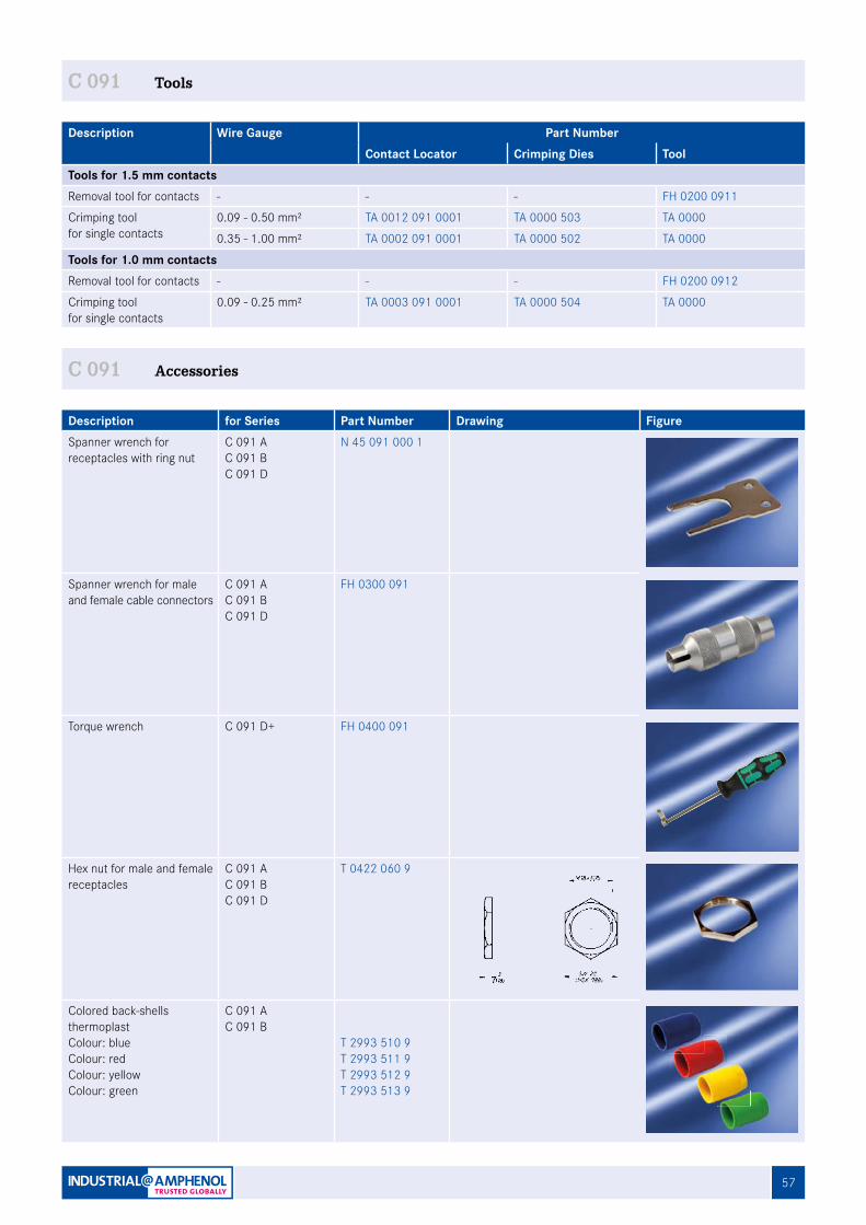
57
C 091 Tools
Description Wire Gauge Part NumberContact Locator Crimping Dies Tool
Tools for 1.5 mm contactsRemoval tool for contacts - - - FH 0200 0911
Crimping tool for single contacts
0.09 - 0.50 mm² TA 0012 091 0001 TA 0000 503 TA 0000
0.35 - 1.00 mm² TA 0002 091 0001 TA 0000 502 TA 0000
Tools for 1.0 mm contactsRemoval tool for contacts - - - FH 0200 0912
Crimping tool for single contacts
0.09 - 0.25 mm² TA 0003 091 0001 TA 0000 504 TA 0000
Description for Series Part Number Drawing FigureSpanner wrench for receptacles with ring nut
C 091 AC 091 BC 091 D
N 45 091 000 1
Spanner wrench for male and female cable connectors
C 091 AC 091 BC 091 D
FH 0300 091
Torque wrench C 091 D+ FH 0400 091
Hex nut for male and female receptacles
C 091 AC 091 BC 091 D
T 0422 060 9
Colored back-shells thermoplastColour: blueColour: red Colour: yellowColour: green
C 091 AC 091 B
T 2993 510 9T 2993 511 9T 2993 512 9T 2993 513 9
C 091 Accessories
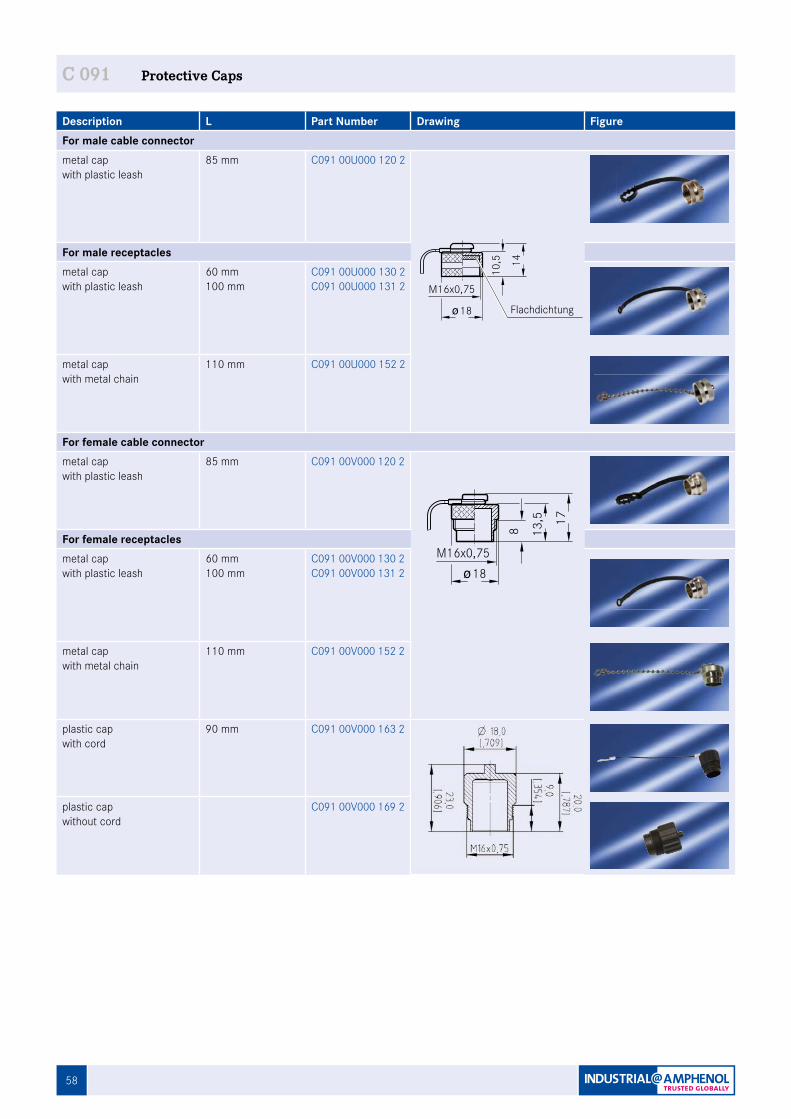
58
Description L Part Number Drawing FigureFor male cable connectormetal cap with plastic leash
85 mm C091 00U000 120 2
For male receptaclesmetal cap with plastic leash
60 mm100 mm
C091 00U000 130 2C091 00U000 131 2
metal capwith metal chain
110 mm C091 00U000 152 2
For female cable connectormetal capwith plastic leash
85 mm C091 00V000 120 2
For female receptaclesmetal capwith plastic leash
60 mm100 mm
C091 00V000 130 2C091 00V000 131 2
metal capwith metal chain
110 mm C091 00V000 152 2
plastic capwith cord
90 mm C091 00V000 163 2
plastic capwithout cord
C091 00V000 169 2
C 091 Protective Caps
18
M16x0,75
14
10,5
Fig. C 091D-97a
Flachdichtung
13,5 17
8
18M16x0,75
Fig. C 091D-98a
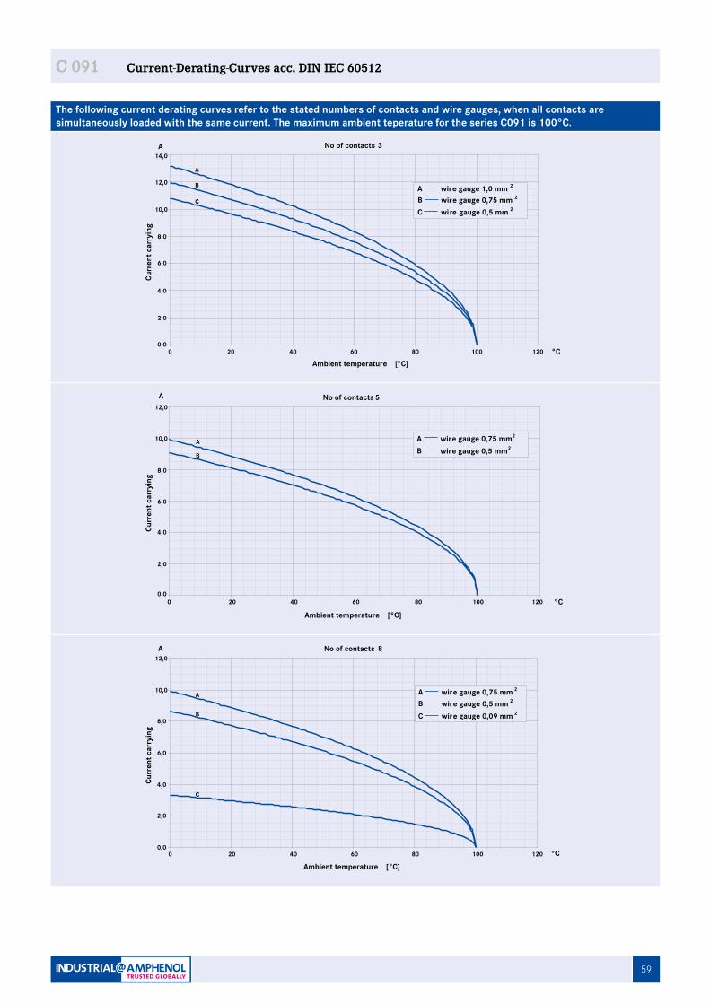
59
C 091 Current-Derating-Curves acc. DIN IEC 60512
The following current derating curves refer to the stated numbers of contacts and wire gauges, when all contacts are simultaneously loaded with the same current. The maximum ambient teperature for the series C091 is 100°C.
0,0
2,0
4,0
6,0
8,0
10,0
12,0
14,0
0 20 40 60 80 100 120
No of contacts 3A
°C
A
B
C wire gauge 0,75 mm 2B wire gauge 0,5 mm 2C
Ambient temperature [°C]
Curr
ent c
arry
ing
wire gauge 1,0 mm 2A
No of contacts 5
0,0
2,0
4,0
6,0
8,0
10,0
12,0
0 20 40 60 80 100 120
A
B
A
°CAmbient temperature [°C]
Curr
ent c
arry
ing
wire gauge 0,75 mm2A wire gauge 0,5 mm2B
0,0
2,0
4,0
6,0
8,0
10,0
12,0
0 20 40 60 80 100 120
Ambient temperature [°C]
Curr
ent c
arry
ing
A
°C
A
B
C
wire gauge 0,09 mm 2C wire gauge 0,5 mm 2B wire gauge 0,75 mm 2A
No of contacts 8
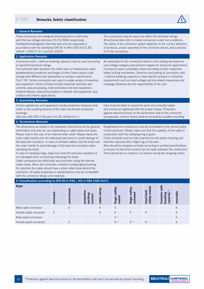
60 1) Protection against electrical shock on the termination side has to be secured by proper mounting.
C 091 Remarks, Safety classification
1. General RemarksThese connectors are designed and produced in conformity with the low voltage directive (73/23/EWG) respectively Gerätesicherheitsgesetz (German law) and are especially in accordance with the standards DIN EN 61984 (VDE 0627); IEC 60664-1 (VDE 0110-1) and IEC 60529.
The connectors may be used only within the technical ratings.All technical data refer to mated connectors under live conditions. The safety of the connector system depends on the correct selection of products, proper assembly of the connector device, and a precise fit of the connectors.
2. Application RemarksConnectors with / without breaking capacity must be used according to specified technical ratings.The technical data represent the initial value of mated parts under predetermined conditions and length of time.These values could change with different test parameters or product requirements.The C 091 Series connectors are used in a wide variety of industries and equipment. Some of these include industrial machines and controls, data processing, instrumentation and test equipment, medical devices, telecommunication’s network and equipment, plus outdoor and marine applications.
All rated data for the connectors listed in this catalog are based on over-voltage category and pollution degree for electronic applications. Connectors were completely mated according to their respective safety locking mechanism. Selection and testing of connectors with / without breaking capacity to meet specific product or industrial requirements such as rated voltage and the related clearances and creepage distances are the responsibility of the user.
3. Assembling RemarksCertain appliances and equipment include protective measures that relate to the coupling devices of the male and female receptacle housings. (See also DIN VDE 0100 part 410; IEC 60364-4-41.)
Care must be taken to insure the parts are correctly mated and screws are tightened with the proper torque. Protection against electrical shock on the termination side of the connector (receptacles, contact insert) shall be secured by suitable mounting.
4. Termination RemarksThe dimensions as stated in the assembly instructions are for general information only and can vary depending on cable styles and types.Please note in the case of an internal strain relief: Always clamp the outer cable mantle (not the individual lead wires) to avoid damage of the lead wire insulation. In case of shielded cables, fold the braid over the outer mantle to avoid damage of the lead wire insulation when clamping the braid.In case of clamping rings, make sure that the lead wire insulation is not damaged when connecting (clamping) the braid.Cable connectors are effectively secured when using the internal cable clamp. When the connector contains a simple gland bushing for retention the cable should have a strain relief close behind the connector. All cable properties or specifications must be compatible with the connector design and materials.
Designated wire conductors must be terminated to the correct poles in the connector. Please make sure that the usability of the cable in conjunction with the clamping ring is given.Crimp contacts must be fully inserted into the plastic housing and retention assured with a slight tug on the wire.Wire should be stripped correctly according to printed specifications to ensure no electrical contact can be made between the conductors. There should be no nicked or cut strains during the stripping action.
5. Classification according to DIN EN 61984 / IEC 61984 (VDE 0627)
Style
encl
osed
unen
clos
ed
prot
ectiv
e ea
rthi
ng
cont
act
cabl
e cl
amp
finge
r saf
ety
m
ated
finge
r saf
ety
un
mat
ed
hand
bac
k sa
fety
mat
ed
Conn
etor
with
br
eaki
ng
capa
city
1)
rew
irabl
e
Male cable connector X X X XFemale cable connector X X X X X XMale panel connector X 1) XFemale panel connector X X 1) X 1) X 1) X
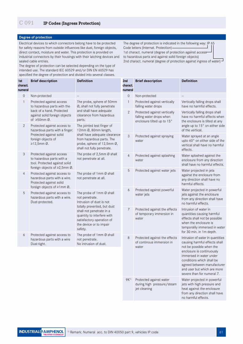
611) Remark: Numeral acc. to DIN 40050 part 9, vehicles IP code
Degree of protectionElectrical devices to which connectors belong have to be protected for safety reasons from outside influences like dust, foreign objects, direct contact, moisture and water. This protection is provided on industrial connectors by their housings with their latching devices and sealed cable entries. The degree of protection can be selected depending on the type of intended use. The standard IEC 60529 and/or DIN EN 60529 has specified the degree of protection and divided into several classes.
The degree of protection is indicated in the following way: IP 65Code letters (Internat. Protection)1st charact. numeral (degree of protection against access to hazardous parts and against solid foreign objects)2nd charact. numeral (degree of protection against ingress of water)
C 091 IP Codes (Ingress Protection)
2ndcharact.numeral
Brief description Definition
0 Non-protected --
1 Protected against vertically falling water drops
Vertically falling drops shall have no harmful effects.
2 Protected against vertically falling water drops when enclosure tilted up to 15°
Vertically falling drops shall have no harmful effects when the enclosure is tilted at any angle up to 15° on either side of the vertical.
3 Protected against spraying water
Water sprayed at an angle upto 60° on either side of the vertical shall have no harmful effects.
4 Protected against splashing water
Water splashed against the enclosure from any direction shall have no harmful effects.
5 Protected against water jets Water projected in jets against the enclosure from any direction shall have no harmful effects.
6 Protected against powerful water jets
Water projected in powerful jets against the enclosure from any direction shall have no harmful effects.
7 Protected against the effects of temporary immersion in water
Intrusion of water in quantities causing harmful effects shall not be possible when the enclosure is temporalily immersed in water for 30 min. in 1m depth.
8 Protected against the effects of continous immersion in water
Intrusion of water in quantities causing harmful effects shall not be possible when the enclosure is continuously immersed in water under conditions which shall be agreed between manufacturer and user but which are more severe than for numeral 7.
9K1) Protected against water during high pressure/steam jet cleaning
Water projected in powerful jets with high pressure and heat against the enclosure from any direction shall have no harmful effects.
1st charact.numeral
Brief description Definition
0 Non-protected --
1 Protected against access to hazardous parts with the back of a hand. Protected against solid foreign objects of ≥50mm Ø.
The probe, sphere of 50mm Ø, shall not fully penetrate and shall have adequate clearance from hazardous parts.
2 Protected against access to hazardous parts with a finger.Protected against solid foreign objects of≥12,5mm Ø.
The jointed test finger of 12mm Ø, 80mm length, shall have adequate clearance from hazardous parts. The probe, sphere of 12,5mm Ø, shall not fully penetrate.
3 Protected against access to hazardous parts with a tool. Protected against solid foreign objects of ≥2,5mm Ø.
The probe of 2,5mm Ø shall not penetrate at all.
4 Protected against access to hazardous parts with a wire.Protected against solid foreign objects of ≥1mm Ø.
The probe of 1mm Ø shall not penetrate at all.
5 Protected against access to hazardous parts with a wire.Dust-protected.
The probe of 1mm Ø shall not penetrate.Intrusion of dust is not totally prevented, but dust shall not penetrate in a quantity to interfere with satisfactory operation of the device or to impair safety.
6 Protected against access to hazardous parts with a wireDust-tight.
The probe of 1mm Ø shall not penetrate.No intrusion of dust.
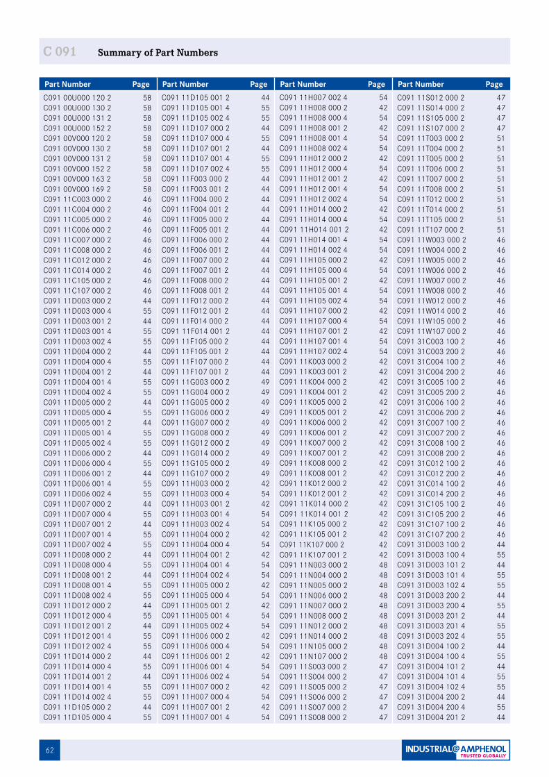
62
C 091 Summary of Part Numbers
Part Number Page Part Number Page Part Number Page Part Number PageC091 00U000 120 2 58C091 00U000 130 2 58C091 00U000 131 2 58C091 00U000 152 2 58C091 00V000 120 2 58C091 00V000 130 2 58C091 00V000 131 2 58C091 00V000 152 2 58C091 00V000 163 2 58C091 00V000 169 2 58C091 11C003 000 2 46C091 11C004 000 2 46C091 11C005 000 2 46C091 11C006 000 2 46C091 11C007 000 2 46C091 11C008 000 2 46C091 11C012 000 2 46C091 11C014 000 2 46C091 11C105 000 2 46C091 11C107 000 2 46C091 11D003 000 2 44C091 11D003 000 4 55C091 11D003 001 2 44C091 11D003 001 4 55C091 11D003 002 4 55C091 11D004 000 2 44C091 11D004 000 4 55C091 11D004 001 2 44C091 11D004 001 4 55C091 11D004 002 4 55C091 11D005 000 2 44C091 11D005 000 4 55C091 11D005 001 2 44C091 11D005 001 4 55C091 11D005 002 4 55C091 11D006 000 2 44C091 11D006 000 4 55C091 11D006 001 2 44C091 11D006 001 4 55C091 11D006 002 4 55C091 11D007 000 2 44C091 11D007 000 4 55C091 11D007 001 2 44C091 11D007 001 4 55C091 11D007 002 4 55C091 11D008 000 2 44C091 11D008 000 4 55C091 11D008 001 2 44C091 11D008 001 4 55C091 11D008 002 4 55C091 11D012 000 2 44C091 11D012 000 4 55C091 11D012 001 2 44C091 11D012 001 4 55C091 11D012 002 4 55C091 11D014 000 2 44C091 11D014 000 4 55C091 11D014 001 2 44C091 11D014 001 4 55C091 11D014 002 4 55C091 11D105 000 2 44C091 11D105 000 4 55
C091 11D105 001 2 44C091 11D105 001 4 55C091 11D105 002 4 55C091 11D107 000 2 44C091 11D107 000 4 55C091 11D107 001 2 44C091 11D107 001 4 55C091 11D107 002 4 55C091 11F003 000 2 44C091 11F003 001 2 44C091 11F004 000 2 44C091 11F004 001 2 44C091 11F005 000 2 44C091 11F005 001 2 44C091 11F006 000 2 44C091 11F006 001 2 44C091 11F007 000 2 44C091 11F007 001 2 44C091 11F008 000 2 44C091 11F008 001 2 44C091 11F012 000 2 44C091 11F012 001 2 44C091 11F014 000 2 44C091 11F014 001 2 44C091 11F105 000 2 44C091 11F105 001 2 44C091 11F107 000 2 44C091 11F107 001 2 44C091 11G003 000 2 49C091 11G004 000 2 49C091 11G005 000 2 49C091 11G006 000 2 49C091 11G007 000 2 49C091 11G008 000 2 49C091 11G012 000 2 49C091 11G014 000 2 49C091 11G105 000 2 49C091 11G107 000 2 49C091 11H003 000 2 42C091 11H003 000 4 54C091 11H003 001 2 42C091 11H003 001 4 54C091 11H003 002 4 54C091 11H004 000 2 42C091 11H004 000 4 54C091 11H004 001 2 42C091 11H004 001 4 54C091 11H004 002 4 54C091 11H005 000 2 42C091 11H005 000 4 54C091 11H005 001 2 42C091 11H005 001 4 54C091 11H005 002 4 54C091 11H006 000 2 42C091 11H006 000 4 54C091 11H006 001 2 42C091 11H006 001 4 54C091 11H006 002 4 54C091 11H007 000 2 42C091 11H007 000 4 54C091 11H007 001 2 42C091 11H007 001 4 54
C091 11H007 002 4 54C091 11H008 000 2 42C091 11H008 000 4 54C091 11H008 001 2 42C091 11H008 001 4 54C091 11H008 002 4 54C091 11H012 000 2 42C091 11H012 000 4 54C091 11H012 001 2 42C091 11H012 001 4 54C091 11H012 002 4 54C091 11H014 000 2 42C091 11H014 000 4 54C091 11H014 001 2 42C091 11H014 001 4 54C091 11H014 002 4 54C091 11H105 000 2 42C091 11H105 000 4 54C091 11H105 001 2 42C091 11H105 001 4 54C091 11H105 002 4 54C091 11H107 000 2 42C091 11H107 000 4 54C091 11H107 001 2 42C091 11H107 001 4 54C091 11H107 002 4 54C091 11K003 000 2 42C091 11K003 001 2 42C091 11K004 000 2 42C091 11K004 001 2 42C091 11K005 000 2 42C091 11K005 001 2 42C091 11K006 000 2 42C091 11K006 001 2 42C091 11K007 000 2 42C091 11K007 001 2 42C091 11K008 000 2 42C091 11K008 001 2 42C091 11K012 000 2 42C091 11K012 001 2 42C091 11K014 000 2 42C091 11K014 001 2 42C091 11K105 000 2 42C091 11K105 001 2 42C091 11K107 000 2 42C091 11K107 001 2 42C091 11N003 000 2 48C091 11N004 000 2 48C091 11N005 000 2 48C091 11N006 000 2 48C091 11N007 000 2 48C091 11N008 000 2 48C091 11N012 000 2 48C091 11N014 000 2 48C091 11N105 000 2 48C091 11N107 000 2 48C091 11S003 000 2 47C091 11S004 000 2 47C091 11S005 000 2 47C091 11S006 000 2 47C091 11S007 000 2 47C091 11S008 000 2 47
C091 11S012 000 2 47C091 11S014 000 2 47C091 11S105 000 2 47C091 11S107 000 2 47C091 11T003 000 2 51C091 11T004 000 2 51C091 11T005 000 2 51C091 11T006 000 2 51C091 11T007 000 2 51C091 11T008 000 2 51C091 11T012 000 2 51C091 11T014 000 2 51C091 11T105 000 2 51C091 11T107 000 2 51C091 11W003 000 2 46C091 11W004 000 2 46C091 11W005 000 2 46C091 11W006 000 2 46C091 11W007 000 2 46C091 11W008 000 2 46C091 11W012 000 2 46C091 11W014 000 2 46C091 11W105 000 2 46C091 11W107 000 2 46C091 31C003 100 2 46C091 31C003 200 2 46C091 31C004 100 2 46C091 31C004 200 2 46C091 31C005 100 2 46C091 31C005 200 2 46C091 31C006 100 2 46C091 31C006 200 2 46C091 31C007 100 2 46C091 31C007 200 2 46C091 31C008 100 2 46C091 31C008 200 2 46C091 31C012 100 2 46C091 31C012 200 2 46C091 31C014 100 2 46C091 31C014 200 2 46C091 31C105 100 2 46C091 31C105 200 2 46C091 31C107 100 2 46C091 31C107 200 2 46C091 31D003 100 2 44C091 31D003 100 4 55C091 31D003 101 2 44C091 31D003 101 4 55C091 31D003 102 4 55C091 31D003 200 2 44C091 31D003 200 4 55C091 31D003 201 2 44C091 31D003 201 4 55C091 31D003 202 4 55C091 31D004 100 2 44C091 31D004 100 4 55C091 31D004 101 2 44C091 31D004 101 4 55C091 31D004 102 4 55C091 31D004 200 2 44C091 31D004 200 4 55C091 31D004 201 2 44
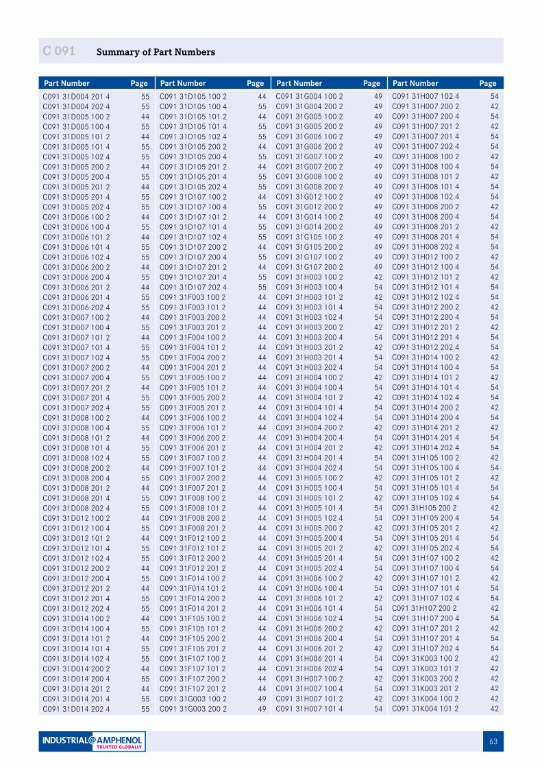
63
C 091 Summary of Part Numbers
Part Number Page Part Number Page Part Number Page Part Number PageC091 31D004 201 4 55C091 31D004 202 4 55C091 31D005 100 2 44C091 31D005 100 4 55C091 31D005 101 2 44C091 31D005 101 4 55C091 31D005 102 4 55C091 31D005 200 2 44C091 31D005 200 4 55C091 31D005 201 2 44C091 31D005 201 4 55C091 31D005 202 4 55C091 31D006 100 2 44C091 31D006 100 4 55C091 31D006 101 2 44C091 31D006 101 4 55C091 31D006 102 4 55C091 31D006 200 2 44C091 31D006 200 4 55C091 31D006 201 2 44C091 31D006 201 4 55C091 31D006 202 4 55C091 31D007 100 2 44C091 31D007 100 4 55C091 31D007 101 2 44C091 31D007 101 4 55C091 31D007 102 4 55C091 31D007 200 2 44C091 31D007 200 4 55C091 31D007 201 2 44C091 31D007 201 4 55C091 31D007 202 4 55C091 31D008 100 2 44C091 31D008 100 4 55C091 31D008 101 2 44C091 31D008 101 4 55C091 31D008 102 4 55C091 31D008 200 2 44C091 31D008 200 4 55C091 31D008 201 2 44C091 31D008 201 4 55C091 31D008 202 4 55C091 31D012 100 2 44C091 31D012 100 4 55C091 31D012 101 2 44C091 31D012 101 4 55C091 31D012 102 4 55C091 31D012 200 2 44C091 31D012 200 4 55C091 31D012 201 2 44C091 31D012 201 4 55C091 31D012 202 4 55C091 31D014 100 2 44C091 31D014 100 4 55C091 31D014 101 2 44C091 31D014 101 4 55C091 31D014 102 4 55C091 31D014 200 2 44C091 31D014 200 4 55C091 31D014 201 2 44C091 31D014 201 4 55C091 31D014 202 4 55
C091 31D105 100 2 44C091 31D105 100 4 55C091 31D105 101 2 44C091 31D105 101 4 55C091 31D105 102 4 55C091 31D105 200 2 44C091 31D105 200 4 55C091 31D105 201 2 44C091 31D105 201 4 55C091 31D105 202 4 55C091 31D107 100 2 44C091 31D107 100 4 55C091 31D107 101 2 44C091 31D107 101 4 55C091 31D107 102 4 55C091 31D107 200 2 44C091 31D107 200 4 55C091 31D107 201 2 44C091 31D107 201 4 55C091 31D107 202 4 55C091 31F003 100 2 44C091 31F003 101 2 44C091 31F003 200 2 44C091 31F003 201 2 44C091 31F004 100 2 44C091 31F004 101 2 44C091 31F004 200 2 44C091 31F004 201 2 44C091 31F005 100 2 44C091 31F005 101 2 44C091 31F005 200 2 44C091 31F005 201 2 44C091 31F006 100 2 44C091 31F006 101 2 44C091 31F006 200 2 44C091 31F006 201 2 44C091 31F007 100 2 44C091 31F007 101 2 44C091 31F007 200 2 44C091 31F007 201 2 44C091 31F008 100 2 44C091 31F008 101 2 44C091 31F008 200 2 44C091 31F008 201 2 44C091 31F012 100 2 44C091 31F012 101 2 44C091 31F012 200 2 44C091 31F012 201 2 44C091 31F014 100 2 44C091 31F014 101 2 44C091 31F014 200 2 44C091 31F014 201 2 44C091 31F105 100 2 44C091 31F105 101 2 44C091 31F105 200 2 44C091 31F105 201 2 44C091 31F107 100 2 44C091 31F107 101 2 44C091 31F107 200 2 44C091 31F107 201 2 44C091 31G003 100 2 49C091 31G003 200 2 49
C091 31G004 100 2 49C091 31G004 200 2 49C091 31G005 100 2 49C091 31G005 200 2 49C091 31G006 100 2 49C091 31G006 200 2 49C091 31G007 100 2 49C091 31G007 200 2 49C091 31G008 100 2 49C091 31G008 200 2 49C091 31G012 100 2 49C091 31G012 200 2 49C091 31G014 100 2 49C091 31G014 200 2 49C091 31G105 100 2 49C091 31G105 200 2 49C091 31G107 100 2 49C091 31G107 200 2 49C091 31H003 100 2 42C091 31H003 100 4 54C091 31H003 101 2 42C091 31H003 101 4 54C091 31H003 102 4 54C091 31H003 200 2 42C091 31H003 200 4 54C091 31H003 201 2 42C091 31H003 201 4 54C091 31H003 202 4 54C091 31H004 100 2 42C091 31H004 100 4 54C091 31H004 101 2 42C091 31H004 101 4 54C091 31H004 102 4 54C091 31H004 200 2 42C091 31H004 200 4 54C091 31H004 201 2 42C091 31H004 201 4 54C091 31H004 202 4 54C091 31H005 100 2 42C091 31H005 100 4 54C091 31H005 101 2 42C091 31H005 101 4 54C091 31H005 102 4 54C091 31H005 200 2 42C091 31H005 200 4 54C091 31H005 201 2 42C091 31H005 201 4 54C091 31H005 202 4 54C091 31H006 100 2 42C091 31H006 100 4 54C091 31H006 101 2 42C091 31H006 101 4 54C091 31H006 102 4 54C091 31H006 200 2 42C091 31H006 200 4 54C091 31H006 201 2 42C091 31H006 201 4 54C091 31H006 202 4 54C091 31H007 100 2 42C091 31H007 100 4 54C091 31H007 101 2 42C091 31H007 101 4 54
C091 31H007 102 4 54C091 31H007 200 2 42C091 31H007 200 4 54C091 31H007 201 2 42C091 31H007 201 4 54C091 31H007 202 4 54C091 31H008 100 2 42C091 31H008 100 4 54C091 31H008 101 2 42C091 31H008 101 4 54C091 31H008 102 4 54C091 31H008 200 2 42C091 31H008 200 4 54C091 31H008 201 2 42C091 31H008 201 4 54C091 31H008 202 4 54C091 31H012 100 2 42C091 31H012 100 4 54C091 31H012 101 2 42C091 31H012 101 4 54C091 31H012 102 4 54C091 31H012 200 2 42C091 31H012 200 4 54C091 31H012 201 2 42C091 31H012 201 4 54C091 31H012 202 4 54C091 31H014 100 2 42C091 31H014 100 4 54C091 31H014 101 2 42C091 31H014 101 4 54C091 31H014 102 4 54C091 31H014 200 2 42C091 31H014 200 4 54C091 31H014 201 2 42C091 31H014 201 4 54C091 31H014 202 4 54C091 31H105 100 2 42C091 31H105 100 4 54C091 31H105 101 2 42C091 31H105 101 4 54C091 31H105 102 4 54C091 31H105 200 2 42C091 31H105 200 4 54C091 31H105 201 2 42C091 31H105 201 4 54C091 31H105 202 4 54C091 31H107 100 2 42C091 31H107 100 4 54C091 31H107 101 2 42C091 31H107 101 4 54C091 31H107 102 4 54C091 31H107 200 2 42C091 31H107 200 4 54C091 31H107 201 2 42C091 31H107 201 4 54C091 31H107 202 4 54C091 31K003 100 2 42C091 31K003 101 2 42C091 31K003 200 2 42C091 31K003 201 2 42C091 31K004 100 2 42C091 31K004 101 2 42
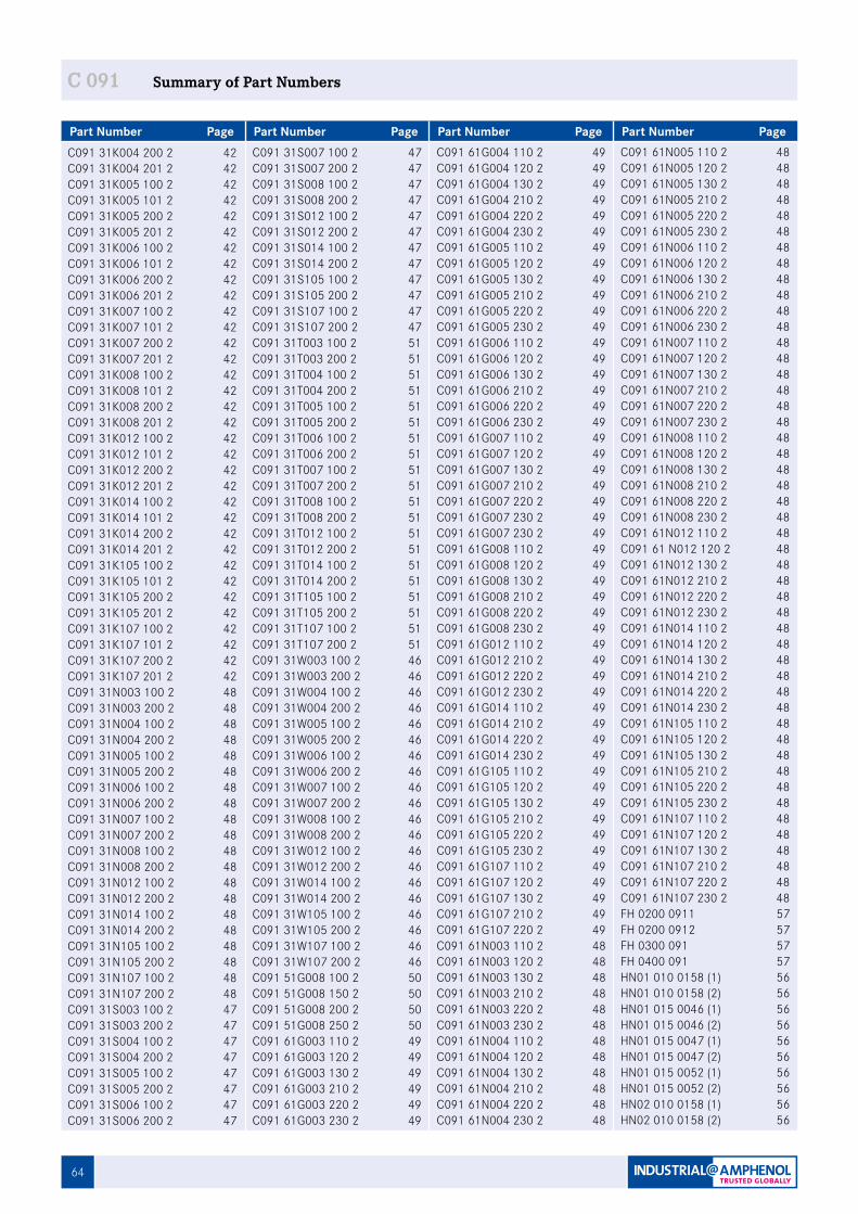
64
Part Number Page Part Number Page Part Number Page Part Number Page
C 091 Summary of Part Numbers
C091 31K004 200 2 42C091 31K004 201 2 42C091 31K005 100 2 42C091 31K005 101 2 42C091 31K005 200 2 42C091 31K005 201 2 42C091 31K006 100 2 42C091 31K006 101 2 42C091 31K006 200 2 42C091 31K006 201 2 42C091 31K007 100 2 42C091 31K007 101 2 42C091 31K007 200 2 42C091 31K007 201 2 42C091 31K008 100 2 42C091 31K008 101 2 42C091 31K008 200 2 42C091 31K008 201 2 42C091 31K012 100 2 42C091 31K012 101 2 42C091 31K012 200 2 42C091 31K012 201 2 42C091 31K014 100 2 42C091 31K014 101 2 42C091 31K014 200 2 42C091 31K014 201 2 42C091 31K105 100 2 42C091 31K105 101 2 42C091 31K105 200 2 42C091 31K105 201 2 42C091 31K107 100 2 42C091 31K107 101 2 42C091 31K107 200 2 42C091 31K107 201 2 42C091 31N003 100 2 48C091 31N003 200 2 48C091 31N004 100 2 48C091 31N004 200 2 48C091 31N005 100 2 48C091 31N005 200 2 48C091 31N006 100 2 48C091 31N006 200 2 48C091 31N007 100 2 48C091 31N007 200 2 48C091 31N008 100 2 48C091 31N008 200 2 48C091 31N012 100 2 48C091 31N012 200 2 48C091 31N014 100 2 48C091 31N014 200 2 48C091 31N105 100 2 48C091 31N105 200 2 48C091 31N107 100 2 48C091 31N107 200 2 48C091 31S003 100 2 47C091 31S003 200 2 47C091 31S004 100 2 47C091 31S004 200 2 47C091 31S005 100 2 47C091 31S005 200 2 47C091 31S006 100 2 47C091 31S006 200 2 47
C091 31S007 100 2 47C091 31S007 200 2 47C091 31S008 100 2 47C091 31S008 200 2 47C091 31S012 100 2 47C091 31S012 200 2 47C091 31S014 100 2 47C091 31S014 200 2 47C091 31S105 100 2 47C091 31S105 200 2 47C091 31S107 100 2 47C091 31S107 200 2 47C091 31T003 100 2 51C091 31T003 200 2 51C091 31T004 100 2 51C091 31T004 200 2 51C091 31T005 100 2 51C091 31T005 200 2 51C091 31T006 100 2 51C091 31T006 200 2 51C091 31T007 100 2 51C091 31T007 200 2 51C091 31T008 100 2 51C091 31T008 200 2 51C091 31T012 100 2 51C091 31T012 200 2 51C091 31T014 100 2 51C091 31T014 200 2 51C091 31T105 100 2 51C091 31T105 200 2 51C091 31T107 100 2 51C091 31T107 200 2 51C091 31W003 100 2 46C091 31W003 200 2 46C091 31W004 100 2 46C091 31W004 200 2 46C091 31W005 100 2 46C091 31W005 200 2 46C091 31W006 100 2 46C091 31W006 200 2 46C091 31W007 100 2 46C091 31W007 200 2 46C091 31W008 100 2 46C091 31W008 200 2 46C091 31W012 100 2 46C091 31W012 200 2 46C091 31W014 100 2 46C091 31W014 200 2 46C091 31W105 100 2 46C091 31W105 200 2 46C091 31W107 100 2 46C091 31W107 200 2 46C091 51G008 100 2 50C091 51G008 150 2 50C091 51G008 200 2 50C091 51G008 250 2 50C091 61G003 110 2 49C091 61G003 120 2 49C091 61G003 130 2 49C091 61G003 210 2 49C091 61G003 220 2 49C091 61G003 230 2 49
C091 61G004 110 2 49C091 61G004 120 2 49C091 61G004 130 2 49C091 61G004 210 2 49C091 61G004 220 2 49C091 61G004 230 2 49C091 61G005 110 2 49C091 61G005 120 2 49C091 61G005 130 2 49C091 61G005 210 2 49C091 61G005 220 2 49C091 61G005 230 2 49C091 61G006 110 2 49C091 61G006 120 2 49C091 61G006 130 2 49C091 61G006 210 2 49C091 61G006 220 2 49C091 61G006 230 2 49C091 61G007 110 2 49C091 61G007 120 2 49C091 61G007 130 2 49C091 61G007 210 2 49C091 61G007 220 2 49C091 61G007 230 2 49C091 61G007 230 2 49C091 61G008 110 2 49C091 61G008 120 2 49C091 61G008 130 2 49C091 61G008 210 2 49C091 61G008 220 2 49C091 61G008 230 2 49C091 61G012 110 2 49C091 61G012 210 2 49C091 61G012 220 2 49C091 61G012 230 2 49C091 61G014 110 2 49C091 61G014 210 2 49C091 61G014 220 2 49C091 61G014 230 2 49C091 61G105 110 2 49C091 61G105 120 2 49C091 61G105 130 2 49C091 61G105 210 2 49C091 61G105 220 2 49C091 61G105 230 2 49C091 61G107 110 2 49C091 61G107 120 2 49C091 61G107 130 2 49C091 61G107 210 2 49C091 61G107 220 2 49C091 61N003 110 2 48C091 61N003 120 2 48C091 61N003 130 2 48C091 61N003 210 2 48C091 61N003 220 2 48C091 61N003 230 2 48C091 61N004 110 2 48C091 61N004 120 2 48C091 61N004 130 2 48C091 61N004 210 2 48C091 61N004 220 2 48C091 61N004 230 2 48
C091 61N005 110 2 48C091 61N005 120 2 48C091 61N005 130 2 48C091 61N005 210 2 48C091 61N005 220 2 48C091 61N005 230 2 48C091 61N006 110 2 48C091 61N006 120 2 48C091 61N006 130 2 48C091 61N006 210 2 48C091 61N006 220 2 48C091 61N006 230 2 48C091 61N007 110 2 48C091 61N007 120 2 48C091 61N007 130 2 48C091 61N007 210 2 48C091 61N007 220 2 48C091 61N007 230 2 48C091 61N008 110 2 48C091 61N008 120 2 48C091 61N008 130 2 48C091 61N008 210 2 48C091 61N008 220 2 48C091 61N008 230 2 48C091 61N012 110 2 48C091 61 N012 120 2 48C091 61N012 130 2 48C091 61N012 210 2 48C091 61N012 220 2 48C091 61N012 230 2 48C091 61N014 110 2 48C091 61N014 120 2 48C091 61N014 130 2 48C091 61N014 210 2 48C091 61N014 220 2 48C091 61N014 230 2 48C091 61N105 110 2 48C091 61N105 120 2 48C091 61N105 130 2 48C091 61N105 210 2 48C091 61N105 220 2 48C091 61N105 230 2 48C091 61N107 110 2 48C091 61N107 120 2 48C091 61N107 130 2 48C091 61N107 210 2 48C091 61N107 220 2 48C091 61N107 230 2 48FH 0200 0911 57FH 0200 0912 57FH 0300 091 57FH 0400 091 57HN01 010 0158 (1) 56HN01 010 0158 (2) 56HN01 015 0046 (1) 56HN01 015 0046 (2) 56HN01 015 0047 (1) 56HN01 015 0047 (2) 56HN01 015 0052 (1) 56HN01 015 0052 (2) 56HN02 010 0158 (1) 56HN02 010 0158 (2) 56
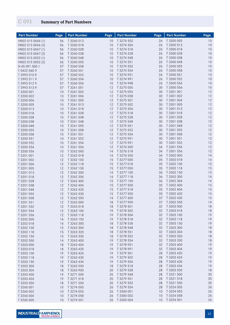
65
Part Number Page Part Number Page Part Number Page Part Number Page
C 091 Summary of Part Numbers
HN02 015 0046 (1) 56HN02 015 0046 (2) 56HN02 015 0047 (1) 56HN02 015 0047 (2) 56HN02 015 0052 (1) 56HN02 015 0052 (2) 56N 45 091 000 1 57T 0422 060 9 57T 2993 510 9 57T 2993 511 9 57T 2993 512 9 57T 2993 513 9 57T 3200 001 10T 3200 002 10T 3200 004 10T 3200 005 10T 3200 013 10T 3200 018 10T 3200 028 10T 3200 038 10T 3200 048 10T 3200 055 10T 3200 058 10T 3200 551 10T 3200 552 10T 3200 554 10T 3200 556 10T 3201 001 12T 3201 002 12T 3201 004 12T 3201 005 12T 3201 013 12T 3201 018 12T 3201 028 12T 3201 038 12T 3201 048 12T 3201 055 12T 3201 058 12T 3201 551 12T 3201 552 12T 3201 554 12T 3201 556 12T 3202 000 14T 3202 018 14T 3202 100 15 T 3202 118 15T 3202 150 15T 3202 550 14T 3203 000 18T 3203 018 18T 3203 100 19T 3203 118 19T 3203 150 19T 3203 300 18T 3203 304 18T 3203 400 19T 3203 404 19T 3203 550 18T 3260 001 10T 3260 002 10T 3260 004 10T 3260 005 10
T 3260 013 10T 3260 018 10T 3260 028 10T 3260 038 10T 3260 048 10T 3260 055 10T 3260 058 10T 3260 551 10T 3260 552 10T 3260 554 10T 3260 556 10T 3261 001 12T 3261 002 12T 3261 004 12T 3261 005 12T 3261 013 12T 3261 018 12T 3261 028 12T 3261 038 12T 3261 048 12T 3261 055 12T 3261 058 12T 3261 551 12T 3261 552 12T 3261 554 12T 3261 556 12T 3262 000 14T 3262 018 14T 3262 100 15T 3262 118 15T 3262 150 15T 3262 300 14T 3262 304 14T 3262 400 15T 3262 404 15T 3262 420 15T 3262 430 15T 3262 550 14T 3263 000 18T 3263 018 18T 3263 100 19T 3263 118 19T 3263 150 19T 3263 300 18T 3263 304 18T 3263 320 18T 3263 330 18T 3263 400 19T 3263 404 19T 3263 420 19T 3263 424 19T 3263 430 19T 3263 434 19T 3263 550 18T 3263 900 20T 3271 500 35T 3271 518 35T 3271 550 35T 3274 005 26T 3274 055 26T 3274 058 26T 3274 501 26
T 3274 502 26T 3274 504 26T 3274 518 26T 3274 528 26T 3274 548 26T 3274 551 26T 3274 552 26T 3274 554 26T 3274 951 26T 3274 991 26T 3274 998 26T 3275 005 30T 3275 055 30T 3275 058 30T 3275 501 30T 3275 502 30T 3275 504 30T 3275 518 30T 3275 528 30T 3275 548 30T 3275 551 30T 3275 552 30T 3275 554 30T 3275 951 30T 3275 991 30T 3276 500 34T 3276 518 34T 3276 550 34T 3277 000 35T 3277 018 35T 3277 050 35T 3277 100 36T 3277 118 36T 3277 150 36T 3277 500 35T 3277 518 35T 3277 550 35T 3277 600 37T 3277 900 37T 3278 501 32T 3278 502 32T 3278 504 32T 3278 518 32T 3278 528 32T 3278 548 32T 3278 551 32T 3278 552 32T 3278 554 32T 3278 951 32T 3278 991 32T 3279 501 28T 3279 502 28T 3279 504 28T 3279 518 28T 3279 528 28T 3279 548 28T 3279 551 28T 3279 552 28T 3279 554 28T 3300 001 10T 3300 002 10T 3300 004 10
T 3300 005 10T 3300 013 10T 3300 018 10T 3300 028 10T 3300 038 10T 3300 048 10T 3300 055 10T 3300 058 10T 3300 551 10T 3300 552 10T 3300 554 10T 3300 556 10T 3301 001 12T 3301 002 12T 3301 004 12T 3301 005 12T 3301 013 12T 3301 018 12T 3301 028 12T 3301 038 12T 3301 048 12T 3301 055 12T 3301 058 12T 3301 551 12T 3301 552 12T 3301 554 12T 3301 556 12T 3302 000 14T 3302 018 14T 3302 100 15T 3302 118 15T 3302 150 15T 3302 300 14T 3302 304 14T 3302 400 15T 3302 404 15T 3302 420 15T 3302 430 15T 3302 550 14T 3303 000 18T 3303 018 18T 3303 100 19T 3303 118 19T 3303 150 19T 3303 300 18T 3303 304 18T 3303 320 18T 3303 330 18T 3303 400 19T 3303 404 19T 3303 420 19T 3303 424 19T 3303 430 19T 3303 434 19T 3303 550 18T 3321 500 35T 3321 518 35T 3321 550 35T 3324 005 26T 3324 055 26T 3324 058 26T 3324 501 26
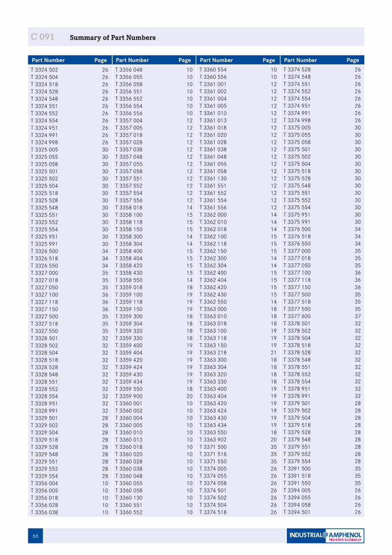
66
Part Number Page Part Number Page Part Number Page Part Number Page
C 091 Summary of Part Numbers
T 3324 502 26T 3324 504 26T 3324 518 26T 3324 528 26T 3324 548 26T 3324 551 26T 3324 552 26T 3324 554 26T 3324 951 26T 3324 991 26T 3324 998 26T 3325 005 30T 3325 055 30T 3325 058 30T 3325 501 30T 3325 502 30T 3325 504 30T 3325 518 30T 3325 528 30T 3325 548 30T 3325 551 30T 3325 552 30T 3325 554 30T 3325 951 30T 3325 991 30T 3326 500 34T 3326 518 34T 3326 550 34T 3327 000 35T 3327 018 35T 3327 050 35T 3327 100 36T 3327 118 36T 3327 150 36T 3327 500 35T 3327 518 35T 3327 550 35T 3328 501 32T 3328 502 32T 3328 504 32T 3328 518 32T 3328 528 32T 3328 548 32T 3328 551 32T 3328 552 32T 3328 554 32T 3328 951 32T 3328 991 32T 3329 501 28T 3329 502 28T 3329 504 28T 3329 518 28T 3329 528 28T 3329 548 28T 3329 551 28T 3329 552 28T 3329 554 28T 3356 004 10T 3356 005 10T 3356 018 10T 3356 028 10T 3356 038 10
T 3356 048 10T 3356 055 10T 3356 058 10T 3356 551 10T 3356 552 10T 3356 554 10T 3356 556 10T 3357 004 12T 3357 005 12T 3357 018 12T 3357 028 12T 3357 038 12T 3357 048 12T 3357 055 12T 3357 058 12T 3357 551 12T 3357 552 12T 3357 554 12T 3357 556 12T 3358 018 14T 3358 100 15T 3358 118 15T 3358 150 15T 3358 300 14T 3358 304 14T 3358 400 15T 3358 404 15T 3358 420 15T 3358 430 15T 3358 550 14T 3359 018 18T 3359 100 19T 3359 118 19T 3359 150 19T 3359 300 18T 3359 304 18T 3359 320 18T 3359 330 18T 3359 400 19T 3359 404 19T 3359 420 19T 3359 424 19T 3359 430 19T 3359 434 19T 3359 550 18T 3359 900 20T 3360 001 10T 3360 002 10T 3360 004 10T 3360 005 10T 3360 010 10T 3360 013 10T 3360 018 10T 3360 020 10T 3360 028 10T 3360 038 10T 3360 048 10T 3360 055 10T 3360 058 10T 3360 130 10T 3360 551 10T 3360 552 10
T 3360 554 10T 3360 556 10T 3361 001 12T 3361 002 12T 3361 004 12T 3361 005 12T 3361 010 12T 3361 013 12T 3361 018 12T 3361 020 12T 3361 028 12T 3361 038 12T 3361 048 12T 3361 055 12T 3361 058 12T 3361 130 12T 3361 551 12T 3361 552 12T 3361 554 12T 3361 556 12T 3362 000 14T 3362 010 14T 3362 018 14T 3362 100 15T 3362 118 15T 3362 150 15T 3362 300 14T 3362 304 14T 3362 400 15T 3362 404 15T 3362 420 15T 3362 430 15T 3362 550 14T 3363 000 18T 3363 010 18T 3363 018 18T 3363 100 19T 3363 118 19T 3363 150 19T 3363 218 21T 3363 300 18T 3363 304 18T 3363 320 18T 3363 330 18T 3363 400 19T 3363 404 19T 3363 420 19T 3363 424 19T 3363 430 19T 3363 434 19T 3363 550 18T 3363 902 20T 3371 500 35T 3371 518 35T 3371 550 35T 3374 005 26T 3374 055 26T 3374 058 26T 3374 501 26T 3374 502 26T 3374 504 26T 3374 518 26
T 3374 528 26T 3374 548 26T 3374 551 26T 3374 552 26T 3374 554 26T 3374 951 26T 3374 991 26T 3374 998 26T 3375 005 30T 3375 055 30T 3375 058 30T 3375 501 30T 3375 502 30T 3375 504 30T 3375 518 30T 3375 528 30T 3375 548 30T 3375 551 30T 3375 552 30T 3375 554 30T 3375 951 30T 3375 991 30T 3376 500 34T 3376 518 34T 3376 550 34T 3377 000 35T 3377 018 35T 3377 050 35T 3377 100 36T 3377 118 36T 3377 150 36T 3377 500 35T 3377 518 35T 3377 550 35T 3377 600 37T 3378 501 32T 3378 502 32T 3378 504 32T 3378 518 32T 3378 528 32T 3378 548 32T 3378 551 32T 3378 552 32T 3378 554 32T 3378 951 32T 3378 991 32T 3379 501 28T 3379 502 28T 3379 504 28T 3379 518 28T 3379 528 28T 3379 548 28T 3379 551 28T 3379 552 28T 3379 554 28T 3391 500 35T 3391 518 35T 3391 550 35T 3394 005 26T 3394 055 26T 3394 058 26T 3394 501 26
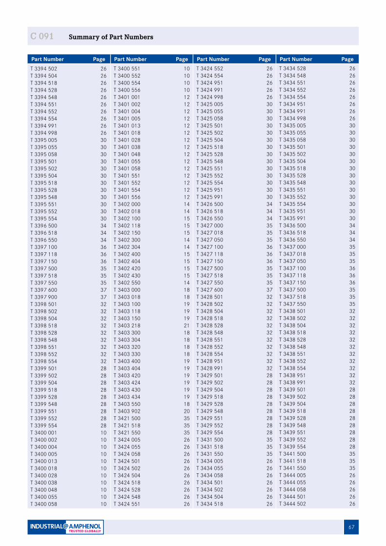
67
Part Number Page Part Number Page Part Number Page Part Number Page
C 091 Summary of Part Numbers
T 3394 502 26T 3394 504 26T 3394 518 26T 3394 528 26T 3394 548 26T 3394 551 26T 3394 552 26T 3394 554 26T 3394 991 26T 3394 998 26T 3395 005 30T 3395 055 30T 3395 058 30T 3395 501 30T 3395 502 30T 3395 504 30T 3395 518 30T 3395 528 30T 3395 548 30T 3395 551 30T 3395 552 30T 3395 554 30T 3396 500 34T 3396 518 34T 3396 550 34T 3397 100 36T 3397 118 36T 3397 150 36T 3397 500 35T 3397 518 35T 3397 550 35T 3397 600 37T 3397 900 37T 3398 501 32T 3398 502 32T 3398 504 32T 3398 518 32T 3398 528 32T 3398 548 32T 3398 551 32T 3398 552 32T 3398 554 32T 3399 501 28T 3399 502 28T 3399 504 28T 3399 518 28T 3399 528 28T 3399 548 28T 3399 551 28T 3399 552 28T 3399 554 28T 3400 001 10T 3400 002 10T 3400 004 10T 3400 005 10T 3400 013 10T 3400 018 10T 3400 028 10T 3400 038 10T 3400 048 10T 3400 055 10T 3400 058 10
T 3400 551 10T 3400 552 10T 3400 554 10T 3400 556 10T 3401 001 12T 3401 002 12T 3401 004 12T 3401 005 12T 3401 013 12T 3401 018 12T 3401 028 12T 3401 038 12T 3401 048 12T 3401 055 12T 3401 058 12T 3401 551 12T 3401 552 12T 3401 554 12T 3401 556 12T 3402 000 14T 3402 018 14T 3402 100 15T 3402 118 15T 3402 150 15T 3402 300 14T 3402 304 14T 3402 400 15T 3402 404 15T 3402 420 15T 3402 430 15T 3402 550 14T 3403 000 18T 3403 018 18T 3403 100 19T 3403 118 19T 3403 150 19T 3403 218 21T 3403 300 18T 3403 304 18T 3403 320 18T 3403 330 18T 3403 400 19T 3403 404 19T 3403 420 19T 3403 424 19T 3403 430 19T 3403 434 19T 3403 550 18T 3403 902 20T 3421 500 35T 3421 518 35T 3421 550 35T 3424 005 26T 3424 055 26T 3424 058 26T 3424 501 26T 3424 502 26T 3424 504 26T 3424 518 26T 3424 528 26T 3424 548 26T 3424 551 26
T 3424 552 26T 3424 554 26T 3424 951 26T 3424 991 26T 3424 998 26T 3425 005 30T 3425 055 30T 3425 058 30T 3425 501 30T 3425 502 30T 3425 504 30T 3425 518 30T 3425 528 30T 3425 548 30T 3425 551 30T 3425 552 30T 3425 554 30T 3425 951 30T 3425 991 30T 3426 500 34T 3426 518 34T 3426 550 34T 3427 000 35T 3427 018 35T 3427 050 35T 3427 100 36T 3427 118 36T 3427 150 36T 3427 500 35T 3427 518 35T 3427 550 35T 3427 600 37T 3428 501 32T 3428 502 32T 3428 504 32T 3428 518 32T 3428 528 32T 3428 548 32T 3428 551 32T 3428 552 32T 3428 554 32T 3428 951 32T 3428 991 32T 3429 501 28T 3429 502 28T 3429 504 28T 3429 518 28T 3429 528 28T 3429 548 28T 3429 551 28T 3429 552 28T 3429 554 28T 3431 500 35T 3431 518 35T 3431 550 35T 3434 005 26T 3434 055 26T 3434 058 26T 3434 501 26T 3434 502 26T 3434 504 26T 3434 518 26
T 3434 528 26T 3434 548 26T 3434 551 26T 3434 552 26T 3434 554 26T 3434 951 26T 3434 991 26T 3434 998 26T 3435 005 30T 3435 055 30T 3435 058 30T 3435 501 30T 3435 502 30T 3435 504 30T 3435 518 30T 3435 528 30T 3435 548 30T 3435 551 30T 3435 552 30T 3435 554 30T 3435 951 30T 3435 991 30T 3436 500 34T 3436 518 34T 3436 550 34T 3437 000 35T 3437 018 35T 3437 050 35T 3437 100 36T 3437 118 36T 3437 150 36T 3437 500 35T 3437 518 35T 3437 550 35T 3438 501 32T 3438 502 32T 3438 504 32T 3438 518 32T 3438 528 32T 3438 548 32T 3438 551 32T 3438 552 32T 3438 554 32T 3438 951 32T 3438 991 32T 3439 501 28T 3439 502 28T 3439 504 28T 3439 518 28T 3439 528 28T 3439 548 28T 3439 551 28T 3439 552 28T 3439 554 28T 3441 500 35T 3441 518 35T 3441 550 35T 3444 005 26T 3444 055 26T 3444 058 26T 3444 501 26T 3444 502 26
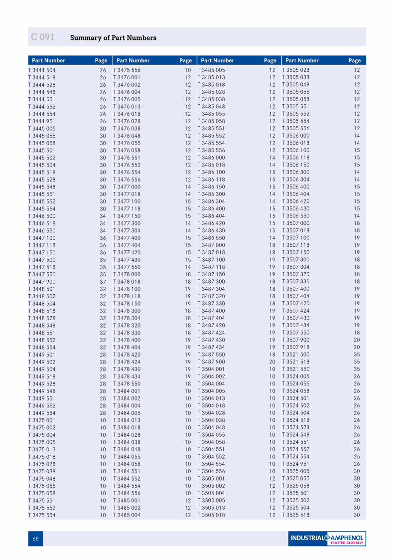
68
C 091 C 091 Summary of Part Numbers
Part Number Page Part Number Page Part Number Page Part Number PageT 3444 504 26T 3444 518 26T 3444 528 26T 3444 548 26T 3444 551 26T 3444 552 26T 3444 554 26T 3444 951 26T 3445 005 30T 3445 055 30T 3445 058 30T 3445 501 30T 3445 502 30T 3445 504 30T 3445 518 30T 3445 528 30T 3445 548 30T 3445 551 30T 3445 552 30T 3445 554 30T 3446 500 34T 3446 518 34T 3446 550 34T 3447 100 36T 3447 118 36T 3447 150 36T 3447 500 35T 3447 518 35T 3447 550 35T 3447 900 37T 3448 501 32T 3448 502 32T 3448 504 32T 3448 518 32T 3448 528 32T 3448 548 32T 3448 551 32T 3448 552 32T 3448 554 32T 3449 501 28T 3449 502 28T 3449 504 28T 3449 518 28T 3449 528 28T 3449 548 28T 3449 551 28T 3449 552 28T 3449 554 28T 3475 001 10T 3475 002 10T 3475 004 10T 3475 005 10T 3475 013 10T 3475 018 10T 3475 028 10T 3475 038 10T 3475 048 10T 3475 055 10T 3475 058 10T 3475 551 10T 3475 552 10T 3475 554 10
T 3475 556 10T 3476 001 12T 3476 002 12T 3476 004 12T 3476 005 12T 3476 013 12T 3476 018 12T 3476 028 12T 3476 038 12T 3476 048 12T 3476 055 12T 3476 058 12T 3476 551 12T 3476 552 12T 3476 554 12T 3476 556 12T 3477 000 14T 3477 018 14T 3477 100 15T 3477 118 15T 3477 150 15T 3477 300 14T 3477 304 14T 3477 400 15T 3477 404 15T 3477 420 15T 3477 430 15T 3477 550 14T 3478 000 18T 3478 018 18T 3478 100 19T 3478 118 19T 3478 150 19T 3478 300 18T 3478 304 18T 3478 320 18T 3478 330 18T 3478 400 19T 3478 404 19T 3478 420 19T 3478 424 19T 3478 430 19T 3478 434 19T 3478 550 18T 3484 001 10T 3484 002 10T 3484 004 10T 3484 005 10T 3484 013 10T 3484 018 10T 3484 028 10T 3484 038 10T 3484 048 10T 3484 055 10T 3484 058 10T 3484 551 10T 3484 552 10T 3484 554 10T 3484 556 10T 3485 001 12T 3485 002 12T 3485 004 12
T 3485 005 12T 3485 013 12T 3485 018 12T 3485 028 12T 3485 038 12T 3485 048 12T 3485 055 12T 3485 058 12T 3485 551 12T 3485 552 12T 3485 554 12T 3485 556 12T 3486 000 14T 3486 018 14T 3486 100 15T 3486 118 15T 3486 150 15T 3486 300 14T 3486 304 14T 3486 400 15T 3486 404 15T 3486 420 15T 3486 430 15T 3486 550 14T 3487 000 18T 3487 018 18T 3487 100 19T 3487 118 19T 3487 150 19T 3487 300 18T 3487 304 18T 3487 320 18T 3487 330 18T 3487 400 19T 3487 404 19T 3487 420 19T 3487 424 19T 3487 430 19T 3487 434 19T 3487 550 18T 3487 900 20T 3504 001 10T 3504 002 10T 3504 004 10T 3504 005 10T 3504 013 10T 3504 018 10T 3504 028 10T 3504 038 10T 3504 048 10T 3504 055 10T 3504 058 10T 3504 551 10T 3504 552 10T 3504 554 10T 3504 556 10T 3505 001 12T 3505 002 12T 3505 004 12T 3505 005 12T 3505 013 12T 3505 018 12
T 3505 028 12T 3505 038 12T 3505 048 12T 3505 055 12T 3505 058 12T 3505 551 12T 3505 552 12T 3505 554 12T 3505 556 12T 3506 000 14T 3506 018 14T 3506 100 15T 3506 118 15T 3506 150 15T 3506 300 14T 3506 304 14T 3506 400 15T 3506 404 15T 3506 420 15T 3506 430 15T 3506 550 14T 3507 000 18T 3507 018 18T 3507 100 19T 3507 118 19T 3507 150 19T 3507 300 18T 3507 304 18T 3507 320 18T 3507 330 18T 3507 400 19T 3507 404 19T 3507 420 19T 3507 424 19T 3507 430 19T 3507 434 19T 3507 550 18T 3507 900 20T 3507 918 20T 3521 500 35T 3521 518 35T 3521 550 35T 3524 005 26T 3524 055 26T 3524 058 26T 3524 501 26T 3524 502 26T 3524 504 26T 3524 518 26T 3524 528 26T 3524 548 26T 3524 551 26T 3524 552 26T 3524 554 26T 3524 951 26T 3525 005 30T 3525 055 30T 3525 058 30T 3525 501 30T 3525 502 30T 3525 504 30T 3525 518 30
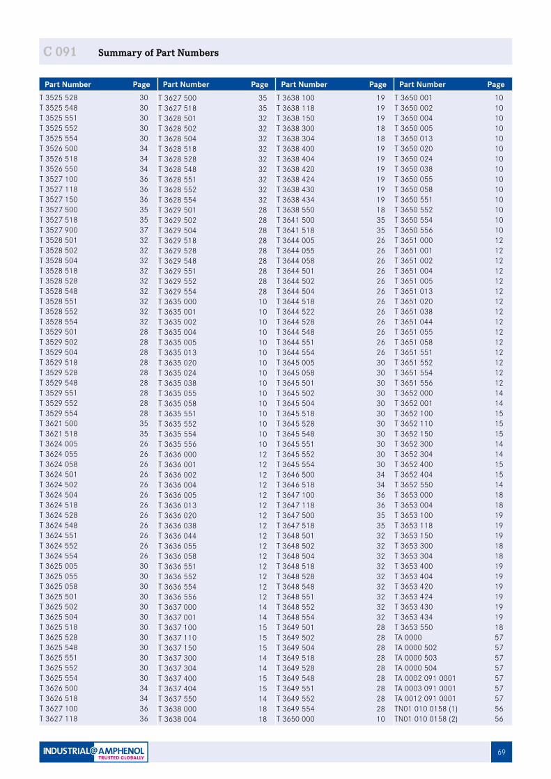
69
C 091 C 091 Summary of Part Numbers
Part Number Page Part Number Page Part Number Page Part Number PageT 3627 500 35T 3627 518 35T 3628 501 32T 3628 502 32T 3628 504 32T 3628 518 32T 3628 528 32T 3628 548 32T 3628 551 32T 3628 552 32T 3628 554 32T 3629 501 28T 3629 502 28T 3629 504 28T 3629 518 28T 3629 528 28T 3629 548 28T 3629 551 28T 3629 552 28T 3629 554 28T 3635 000 10T 3635 001 10T 3635 002 10T 3635 004 10T 3635 005 10T 3635 013 10T 3635 020 10T 3635 024 10T 3635 038 10T 3635 055 10T 3635 058 10T 3635 551 10T 3635 552 10T 3635 554 10T 3635 556 10T 3636 000 12T 3636 001 12T 3636 002 12T 3636 004 12T 3636 005 12T 3636 013 12T 3636 020 12T 3636 038 12T 3636 044 12T 3636 055 12T 3636 058 12T 3636 551 12T 3636 552 12T 3636 554 12T 3636 556 12T 3637 000 14T 3637 001 14T 3637 100 15T 3637 110 15T 3637 150 15T 3637 300 14T 3637 304 14T 3637 400 15T 3637 404 15T 3637 550 14T 3638 000 18T 3638 004 18
T 3638 100 19T 3638 118 19T 3638 150 19T 3638 300 18T 3638 304 18T 3638 400 19T 3638 404 19T 3638 420 19T 3638 424 19T 3638 430 19T 3638 434 19T 3638 550 18T 3641 500 35T 3641 518 35T 3644 005 26T 3644 055 26T 3644 058 26T 3644 501 26T 3644 502 26T 3644 504 26T 3644 518 26T 3644 522 26T 3644 528 26T 3644 548 26T 3644 551 26T 3644 554 26T 3645 005 30T 3645 058 30T 3645 501 30T 3645 502 30T 3645 504 30T 3645 518 30T 3645 528 30T 3645 548 30T 3645 551 30T 3645 552 30T 3645 554 30T 3646 500 34T 3646 518 34T 3647 100 36T 3647 118 36T 3647 500 35T 3647 518 35T 3648 501 32T 3648 502 32T 3648 504 32T 3648 518 32T 3648 528 32T 3648 548 32T 3648 551 32T 3648 552 32T 3648 554 32T 3649 501 28T 3649 502 28T 3649 504 28T 3649 518 28T 3649 528 28T 3649 548 28T 3649 551 28T 3649 552 28T 3649 554 28T 3650 000 10
T 3650 001 10T 3650 002 10T 3650 004 10T 3650 005 10T 3650 013 10T 3650 020 10T 3650 024 10T 3650 038 10T 3650 055 10T 3650 058 10T 3650 551 10T 3650 552 10T 3650 554 10T 3650 556 10T 3651 000 12T 3651 001 12T 3651 002 12T 3651 004 12T 3651 005 12T 3651 013 12T 3651 020 12T 3651 038 12T 3651 044 12T 3651 055 12T 3651 058 12T 3651 551 12T 3651 552 12T 3651 554 12T 3651 556 12T 3652 000 14T 3652 001 14T 3652 100 15T 3652 110 15T 3652 150 15T 3652 300 14T 3652 304 14T 3652 400 15T 3652 404 15T 3652 550 14T 3653 000 18T 3653 004 18T 3653 100 19T 3653 118 19T 3653 150 19T 3653 300 18T 3653 304 18T 3653 400 19T 3653 404 19T 3653 420 19T 3653 424 19T 3653 430 19T 3653 434 19T 3653 550 18TA 0000 57TA 0000 502 57TA 0000 503 57TA 0000 504 57TA 0002 091 0001 57TA 0003 091 0001 57TA 0012 091 0001 57TN01 010 0158 (1) 56TN01 010 0158 (2) 56
T 3525 528 30T 3525 548 30T 3525 551 30T 3525 552 30T 3525 554 30T 3526 500 34T 3526 518 34T 3526 550 34T 3527 100 36T 3527 118 36T 3527 150 36T 3527 500 35T 3527 518 35T 3527 900 37T 3528 501 32T 3528 502 32T 3528 504 32T 3528 518 32T 3528 528 32T 3528 548 32T 3528 551 32T 3528 552 32T 3528 554 32T 3529 501 28T 3529 502 28T 3529 504 28T 3529 518 28T 3529 528 28T 3529 548 28T 3529 551 28T 3529 552 28T 3529 554 28T 3621 500 35T 3621 518 35T 3624 005 26T 3624 055 26T 3624 058 26T 3624 501 26T 3624 502 26T 3624 504 26T 3624 518 26T 3624 528 26T 3624 548 26T 3624 551 26T 3624 552 26T 3624 554 26T 3625 005 30T 3625 055 30T 3625 058 30T 3625 501 30T 3625 502 30T 3625 504 30T 3625 518 30T 3625 528 30T 3625 548 30T 3625 551 30T 3625 552 30T 3625 554 30T 3626 500 34T 3626 518 34T 3627 100 36T 3627 118 36
70
C 091
Part Number Page Part Number Page Part Number Page Part Number Page
C 091 Summary of Part Numbers
TN01 015 0046 (1) 56TN01 015 0046 (2) 56TN01 015 0047 (1) 56TN01 015 0047 (2) 56TN01 015 0052 (1) 56TN01 015 0052 (2) 56TN02 010 0158 (1) 56TN02 010 0158 (2) 56TN02 015 0046 (1) 56TN02 015 0046 (2) 56TN02 015 0047 (1) 56TN02 015 0047 (2) 56TN02 015 0052 (1) 56TN02 015 0052 (2) 56VN01 010 0158 (1) 56VN01 010 0158 (2) 56VN01 015 0046 (1) 56VN01 015 0046 (2) 56VN01 015 0047 (1) 56VN01 015 0047 (2) 56VN01 015 0052 (1) 56VN01 015 0052 (2) 56VN02 010 0158 (1) 56VN02 010 0158 (2) 56VN02 015 0046 (1) 56VN02 015 0046 (2) 56VN02 015 0047 (1) 56VN02 015 0047 (2) 56VN02 015 0052 (1) 56VN02 015 0052 (2) 56ZN01 015 0046 (1) 56ZN01 015 0046 (2) 56ZN01 015 0047 (1) 56ZN01 015 0047 (2) 56ZN02 015 0046 (1) 56ZN02 015 0046 (2) 56ZN02 015 0047 (1) 56ZN02 015 0047 (2) 56

71
C 091 C 091 Your Notes
ATE 3040 B 1115 / 1115 Printed on chlorin-free bleached paper, specifications may be changed without notice. Copyright by Am
phenol-Tuchel Electronics GmbH, Germ
any
Amphenol-Tuchel Electronics GmbH | August -Haeusser Strasse 10 | 74080 Heilbronn, GermanyTelephone: +49 (0)7131 929-0 | Fax: +49 (0)7131 929-486 | www.amphenol.info
Your engineering sales representative:
Important Notice
All technical data have been measured in a laboratory environment and can be different during practical usage of the product. Any product information is for descriptive usage only and not legally binding; particularly the information does not constitute or provide any legal guaranties (“Beschaffenheitsgarantie” or “Haltbarkeitsgarantie”).
We reserve the right to change the design due to improvement in quality, development or production requirements. This catalogue must not be used in any form or manner without our prior approval in writing (Copyright Law, Fair Trading Law, Civil Code).
International
Amphenol SINE SYSTEMS44724 Marley Drive ClintonTownship, MI 48036USATelephone: +1-586-465-3131Fax: +1-586-913-9618
USAAmphenol-TUCHEL ELECTRONICS GMBHAugust-Haeusser-Strasse 1074080 HeilbronnGermanyTelephone +49-7131-929-0 Fax +49-7131-929-486 www.amphenol.de
GERMANYAmphenol TUCHEL ELECTRONICS GMBHChina Branch 20 Tianshan RoadChangzhou 213022ChinaTelephone: +86-519-85110301www.amphenol.info
CHINA
Amphenol DAESHIN558 Sosa, SongNea Bucheon-cityKyunggi-Do Korea 420-130 Telephone : +82-32-610-3800Fax: +82-32-673-2507/665-6219
KOREA AUSTRALIAAmphenol AUSTRALIA PTY LIMITED2 Fiveways Blvd., Keysborough - Melbourne, Victoria 3173AustraliaTelephone: +61-3-8796-8888Fax: +61-3-8796-8801