By: Kyler Zike - Cal Poly
92
Design & Fabrication of an Electric Aircraft Dolly By: Kyler Zike Agricultural Systems Management BioResource and Agricultural Engineering Department California Polytechnic State University San Luis Obispo 2014
Transcript of By: Kyler Zike - Cal Poly

Design & Fabrication of an Electric Aircraft Dolly
By: Kyler Zike
Agricultural Systems Management
BioResource and Agricultural Engineering Department
California Polytechnic State University
San Luis Obispo
2014

TITLE
AUTHOR
DATE SUBMITTED
Dr. Andrew Holtz Senior Project Advisor
Dr. Arthur MacCarley Department Head
SIGNATURE PAGE
Design & Fabrication of an Electric Aircraft Dolly
Kyler Zike
June 13, 2014
aL UJ/!; Signature /
6-13~/t; Date
~Q Signature
Date JE)fb?/
ii

ACKNOWLEDGEMENTS
I would first like to thank my parents for giving me the opportunity to attend Cal Poly. They worked hard in order to give me an experience that they were not provided with and it will never be forgotten. Without their help and support none of this would be possible for me to carry out. College has provided me with the greatest experience of my life. I would also like to thank my uncle for his advice as well as the usage of his machine shop free of charge. Lastly, I would like to thank my advisor Dr. Andrew Holtz for the constructive questioning and the recommendation to use new tools. It has led to many design improvements throughout the building process as well as providing me with a new outlook on building structures.
iii

ABSTRACT
This senior project contains the design, fabrication, and assembly of a lightweight aircraft dolly used to move aircraft to and from its storage site. The report discusses the cost and feasibility of the electric aircraft dolly built. The dolly was built for my father to ease the moving process of his lightweight aircraft.
iv

DISCLAIMER STATEMENT
The university makes it clear that the information forwarded herewith is a project resulting from a class assignment and has been graded and accepted only as a fulfillment of a course requirement. Acceptance by the university does not imply technical accuracy or reliability. Any use of the information in this report is made by the user(s) at his/her own risk, which may include catastrophic failure of the device or infringement of patent or copyright laws.
Therefore, the recipient and/or user of the information contained in this report agrees to indemnify, defend and save harmless the State its officers, agents and employees from any and all claims and losses accruing or resulting to any person, firm, or corporation who may be injured or damaged as a result of the use of this report.
v

TABLE OF CONTENTS
SIGNATURE PAGE ................. . ............................................................... . .... . .. .ii
ACKNOWLEDGEMENTS .... . .. . . . ......... . ... .... . .......... ..... .. ... ... ... . .......... . .......... . ... .. iii
ABSTRACT ......................................... .................. ......... ..... . .... . ...... . ... . ..... . ... .iv
DISCLAIMER STATEMENT ........ ....................... .......... .... ...... ........................................... ......... v
TABLE OF CONTENTS ............... . ..... . .... . .................... . .................................. ... vi
LIST OF FIGURES .. ......... ........ .. .......................... .. ... ... ...... ............................................... ...... ... ... vii
LIST OF TABLES .............. .. ... . . . .......... .. .. . . ................. . .. ...... ............ . . ............... x
INTRODUCTION ............................. .. ......................................... . .................. .. 1
LITERATURE REVIEW ....................... . ..... ..... . ... ... ........ . .......... ..... ............. . ......... 2 TARGET AIRCRAFT ............. . .. ........ ........ .. . ... . ... . ..... .... .. ........ ......... ........................... 2 POWER METHOD .. . .......................................... . ... .. .. ........... .. ......... . ..... . ... . ...... 5
GAS INTERNAL COMBUSTION ENGINE ................. ........................ . .... .. 5 DIC ELECTRIC ..................................................................................... .... 7
LIFTING/MOVING METHOD ............................................................................................. 8 RAMP/SCOOP TILT METHOD .. ... .. ........ ............ .... .......... ...................... ...... .......... 8
CRIMP & LIFT METHOD ................. ............................... .................................... .... ........... 9
AXLE CLASP METHOD . .. ... . .. . ..... . . . ...... .. .......... . .... . ......... . ....... . ........... 1 0 POWERED STEERING METHOD . .................. . . . ............ . . ... . ..... .. ............. 11 HAND MOVE METHOD . ........ . ..... . ................ . ...... ..... ............... ... ......... 12
STEERING METHODS/ GEOMETRY ............... . .. .... . ..... . .... ... . ......... . .............. 13 SINGLE TIRE .. .. .... . .... . ..... . . . .... ................... ... ............................ ..... .. 13 TRIPLE TIRE ....... . ... . ... . .... . ................ . . . ..... . . . ...... . .. . .... . ..... .. . .. ......... 14 R/C ...... . .......... . .... . .. ........ ..... .. ....................................................... 15
COMPETITORS FORT ARGET AIRCRAFT .... . .... .. .. . ....... ... . . .. ..... . .................. 16 PARAMETERS .............................................................................................. 17 PROCEDURES & METHODS ... . . .................... . ... . ............ . ................ .. ...... . ... .. . .. 20
DESIGN PROCEDURE ................. ... .... ............ ........ .................... ..... .. ................ .... .. .... .... .... ... 20 POWERPLANT ............. ... ........... . . .. .... ................... . ....... . ... . ... . ... . ... .. 20 MAIN FRAME MEMBER ............ ..... .... ..... ..... ... ............ .... ... .... ................................ 22 LEFT & RIGHT DRIVE LEGS .............................................................................. ... 24 STEERING LEGIMOTR & GEAR REDUCTION LEG ... ..... .... ....... ............... .. ........ 24 GEOMETRY .... .. .. ..... ............. ........ . ............... .... . ............. , .... ..... . ... . . 28 FABRICATION PROCEDURE ................. ..... ... . ...................... . ............. 30
RESULTS ... ... ... ........................................ .. .......... .. .... .......... ...... .. ...... ........ ...... .. ....... .. ..... .......... ... 47 TESTING ............... ... ......... .... ..... .. .... ... ... ... ... ... ..... ............. .. ............ ..... ...... ..... ........... ...... ... ...... . 47 COST OF PRODUCTION ..... .. .......................... .. ............ ....... ......... ... ... ................................ ........... 51
DISCUSSION ................................................... .............................. ....... ............. ...................... . . 54 RECCOMENDATIONS .......... . ............. . ........ . .... . ................. ..... ....... . .......... ....... 56 REFERENCES ........................................................................................... ....... 57 APPENDICES ..................... . ......... . .... ........ ... . .. ........ ......... . .... .......... . ............ . 59
APPENDIX A ..................................... . ..................................................... . ... 60 APPENDIX B ... . ....... . ......................................... . ....... .... ... . . . ............... . ... .... 62 APPENDIX C ....... . .... . . .. .. .. .. . . ...... . ..... . ............................. . ............................ 68
vi

LIST OF FIGURES
Figure 1: Center of Gravity, Aircraft Geometries ............. ... .. ... . ........... . ......... . .... . ... ..... 2 Figure 2: Standard Geometry Aircraft . .... . ............... . .. . .......... . .... . ..... . ..... ..... .. ....... ..... 2 Figure 3: Tail Dragger Aircraft Geometry .. . ..... . . .. ........... . .. . ......... . ...................... ...... 3 Figure 4: Aviat Husky Al -B. Test Subject .. . . ...... . .. . .. . ...................... . .. . . . .. . . .. ............. .4 Figure 5: Honda GX Series Engine ........... . ..... . ..... . ...... . .. . . . ................ . .. . ..... . ..... ..... . 5 Figure 6: Briggs Gas Engine ... . .. . .... . .................... . . .. .... . .......... . . . ... . . . .... . ... . ............ 5 Figure 7: Honda Gas Engine .. . ...... . .. . .. . . .. . . .. . . . ... . . . ...... . ........ . .. . .. . .. ... .. . ................ .. 6 Figure 8: Briggs & Stratton Gas Engine ...... .... . . . . .......... . ....... . ..... . . . ... .. ...... .... ... . ....... 6 Figure 9: 24VDC Motor. . . ...... ..... . . .. . .. . . . ............ . .. . . ... .. .......... . .. . ..... . . . .. . . .. .. . .......... . 7 Figure 10: D/C Powered Dolly ... . . . . . . .. .. . . . . .. . ... . .. ..... .. . ... . ..... . . . ......... . ... . ........ ..... ..... 7 Figure 11 : Hydraulic Tilt Method . ..... . .. . . . .. . .. . .... .. ..... . ... ....................... . .. . .. . ..... .... .... 8 Figure 12: Scoop & Pivot Method ......... .. ...... . . .. ........... ..... . . . .. . ...... . ........................ 8 Figure 13: Crimp & Lift Method ... . .......................... . .. . .. .. . . . ........... . ........ . . . . ..... ...... 9 Figure 14: Crimp & Lift Method . . . .. . .. . .. ... . .. . .. . . .. . ........ . .. . .. ... .... . .. . . .. . . ......... . .......... . 9 Figure 15: Axle Clasp Method . ... . ...... . .................. . ........ . ............... . . . .. . .......... ... ... 10 Figure 16: Axle Clasp Method ... . ....... . ... .. . .. . .. . . . . . . ............... . ....... . .. . . . ... . .. . .. . ....... .. 10 Figure 17: Gear Driven Mover. .. . ......... .. .... . ... .. .. . .. .............. .. . . . .. .. . .... . .. .. .... . ..... .... 11 Figure 18: Gear Driven Mover ... . .. . .. . .. . . . ............... .. ....... . ... .. ...................... . ......... 11 Figure 19: Gear Driven Mover.. ... ... . .. ..... .. .. . .. .. . . .. . . . . ........... . ........ . .................... . .. . 12 Figure 20: Hand Move Tug Bar ..... . .... .... .. . .... . ... . . . .. . .... .. .... .... . .. .. . ..... . .. . .... . . . ... .. .. . . 12 Figure 21: Single Tire Geometry in use . ... ................ . ............ . .. . ..... .. . . ..... . ... . ......... . . 13 Figure 22: Single tire, Axle Clasp Method .... . ............ . .... . ....... ...... . ............ .............. . .. .... 13 Figure 23: Triple Tire Geometry (Gas) ...... .. ..... . ............. . .. . . . .. .... . ..... . ..................... 14 Figure 24: Triple Tire Geometry, (D/C) . .. . . .... . ... .. ....... ... ... ..... ..... .. . . ... . . . .. . ................. .... .. 14 Figure 25: RIC Mover, Pivot Method .... . . .. . ....... .. .. ... .... . .................... . . .. .... .. .. . . . .. . .. .. 15 Figure 26: RIC Mover, Pivot Method .. . .. . ..... . ............... . ...... . ..... . ......... . ................... 15 Figure 27: Exposed chains and pinch points ........... . ... . .. . .. . . .. .............. .. ... ... ........... . .... 17 Figure 28: External chains and pinch points . . . . . .. . .... ...... .. .... .. ... .... . . .. .. ... . .. .... . .. .. ....... .. 17 Figure 29: Example of loading point over drive tires ..... . ........... . .. . .. ... .. ........... . ... . .. . . .... 18 Figure 30: Example of loading point over drive tires .. ... . . .. ......... . .. . ......... . .............. .. . ... 18 Figure 31: Clearance constraints ... ... .. .. ........ . .. .. . ... .. . . . .. . . . ..... . .................. . .... .......... 19 Figure 32: The 28V DC drill that was disassembled and used to power dolly .. . .. . ............. ..... 20 Figure 33: A rear view of the main frame member. .... . .. . . . ..... . ....... .. ........................... . 22 Figure 34: Front view that dipicts main frame receiver design . ....... . ......... . .... ......... ... . .. . .. 23 Figure 35: View of the drive tire leg . .. . ... ..... .. ... ... . . . . . . . .. . .... . ........................... . ... . ... 24 Figure 36: View of how alluminm legs are mounted with use of 10 guage steel shims . .. . . ..... .. 25 Figure 37: Backside of gear reduction box & chain transfer hole to the mainframe axle . .. . .. ..... 26 Figure 38: View of steering I motor & gear reduction leg . .. .... ....... ................ ......... ................ .. . 27 Figure 39: Structure of frame allowing an equal distribution ofweight.. ........................... ... .28 Figure 40: A front view of the aircraft dolly's deep receptacle capabilities ................. . ....... . 29 Figure 41: Overall view of designed electric aircraft dolly . .... . ........ . .. . ... .. ...... . .. . ... . ....... 29 Figure 42: Using mill to drill locate holes for chain routing .. . . . . . .. .. .. ..... . ......... . .. ............. 30 Figure 43: Jig saw and die grinder used to complete chain routing pathways . . . .. .. . .. . . .... . .. . ... 30
vii i

Figure 44: Depiction of how the receivers were squared and tacked into place .. . ..... . ........... .. 31 Figure 45: View ofTIG weld attaching the reciever to main frame ................................... 32 Figure 46: View offitment of the aluminum leg over the receiver and shims ........ .. . . .. .... ... .. 32 Figure 47: Steering/motor & gear reduction leg reciever .............................................. 33 Figure 48: Gear reduction to mainframe axle chain routing cutout. .................................. 33 Figure 49: Rod and clevis attachment .................................................................... 34 Figure 50: Steering attachment complete on rolling chassis ....... ... ..... . ... ... .. .... ..... . .. ...... . 34 Figure 51: Drilling axle pathway through drive tire leg ..... .. .............. ... .. . ... ...... . . .. .. ...... 35 Figure 52: Drive tire axle assmbly .. .. . .......................... . . .... ... .. . ........................ .. .. .. 35 Figure 53: Rolling chassis placed next to aircraft ....................................................... 36 Figure 54: View of rolling chassis .. . ....... ...... .. .... .. ... .......... . ... ..... .... .......... . .. . .. . . ..... 36 Figure 55: Bearing placed upon carrier. ..... ........ . ......... ..... .... .. .... .. .... ... ......... .. ........ . 37 Figure 56: Main frame bearing carrier . .. . .. ....... .. .. . ..... . . ..... .. ... . .. .................. . . . .......... 37 Figure 57: Main frame axle/sprocket with chain tensioned ..... . ...... . ......... . ... .. ...... . ......... 38 Figure 58: Front side view of chain tensioned ... .. ......... ............. ..... . .......................... 38 Figure 59: Fabricated and welded socket driveshaft .. . ............ . .... ..... . ........... .... . ..... ..... 39 Figure 60: Machined and welded speed reducer shaft ......... .. . . .. ......... .. ... .... ... .............. 39 Figure 61: Drill shaft mounted into gear reduction box ........................ ..... ..... . .. .. .. . .... .. .40 Figure 62: Backside view of drill mounted in frame ................................................... .40 Figure 63: Speed reduction box assembly complete ..................................................... .41 Figure 64: Mounting tab for scoop welded upon main frame member. . .................... . . ... .. .. .42 Figure 65: Drilling adjustable scoop side ................................................................ .42 Figure 66: Adjustable tire plate/ axle pivot plate ........ ............... .... ........ ....... .. .. . .... ... . .43 Figure 67: End mill cutting flat spot on axle ........ . .. . ...... . .. . ............ . ..... ... ......... ...... ... 43 Figure 68: Scoop complete and mounted to main frame .. .... ......... .... . ... .. . ..... ............. ... .44 Figure 69: Scoop complete and mounted to main frame .... ....... . ......................... . ........ . .45 Figure 70: Side view of completed electric aircraft dolly .............................................. .45 Figure 71: Rear view of completed electric aircraft dolly ..... . ...... ..... ..... .. .. .. . ........ . .. . . .. .. .46 Figure 72: Electric aircraft dolly placed next to the Aviat Husky ..................................... .47 Figure 73: View of completed aircraft dolly placed behind the aircraft .............................. .47 Figure 74: View of rear tire ready to be received into aircraft dolly .................................. .48 Figure 75: Rear tire of aircraft loaded into dolly receptacle ....... ... .. .. ...... . . .... . .. .. . .. ......... .48 Figure 76: Rear view of dolly loaded with aircraft ...................................................... .49 Figure 77: Moving the Aviat Husky for the first time with dolly ...................................... .49 Figure 78: Turning the aircraft while in forward motion ................................................ 50 Figure 79: Turning the aircraft while in reverse motion ................................................. 50 Figure 80: Aircraft position after unloading ........ . .... .. . ............. .... .. .... .... .... . .. .. . .. . . .. .. . 51
ix

LIST OF TABLES
Table 1: Tire Diameter/ Gross Weight/ Load Encountered . ............. . ............ . ........... . .4 Table 2: Market Competitors ........................................................................... 16 Table 3: Gear Reduction & Torque Chart ... .. ........... .. .......... . ................ . .............. 21 Table 4: Electric Aircraft Dolly Drive Tire Speed Chart .................................................... 21 Table 5. Cost Breakdown of complete Electric Aircraft Dolly ................... ..... ........... .. 52 Table 6. Labor and Consumable Cost Chart . . ....... ...... ...... .................................... 53
X

INTRODUCTION
Background Aircraft dollies are required in the aid of moving aircraft in and out of hangers to prepare the aircraft for flight. Current manufactured dolly's use small gasoline powered engines or small electric motors powered by alternate or direct current. The dolly moves the aircraft by either attaching to the wheel frame or lifting the single tire up in the air and moving. Current produced machines have external components that create dangerous pinch points and are subsequently not weather proof.
Justification
The goal is to design and fabricate a weather proof dolly that incases all components within the structural frame, reducing the number of pinch points. Also, there is no current aircraft dolly available that loads the tire of the aircraft in the dolly' s center of gravity, which will make steering a fixed axle drive much easier and lead to a much more maneuverable dolly.
Objectives
1
There are several objectives for the design and fabrication of this dolly. The first objective is to successfully incase all the components within the structural frame of the projected aircraft dolly. Powering the dolly with a drill that runs off a lithium ion battery to reduce weight significantly will also be a goal. Another objective will involve constructing a frame that can be bolted together and taken apart to reduce shipping costs if manufactured. Lastly, designing the overall look of the aircraft dolly to match the high standards that are held to the aesthetics of the aircraft it will be moving.

LITERATURE REVIEW
Research was conducted in the library using the PolyCat system on current aircraft moving systems. A significant amount of information was found on methods used to move aircraft, ranging from lightweight personal aircraft, to large commercial size aircraft. Various receiving, powering, and steering methods were discovered and will be discussed in the following pages.
Target Aircraft. The target aircraft that the project will be designed for are classified as lightweight aircraft. This specific class of aircraft is described as an aircraft that has a maximum takeoff weight of 12,000. Both standard and tail geometry build platforms are used on these lightweight aircraft. A standard geometry aircraft is equipped with one front tire and two in the rear of the plane; this is also commonly referred to as a trike. While a tail dragger aircraft is equipped with two front tires and one rear. The Figure 1 below shows both geometries and the location of each class's center of gravity.
Figure 1. Center of Gravity, Aircraft Geometries. (RC, 2013).
2
The center of gravity on the trike design is located very tightly between the three tires therefore, the weight encountered by both the front and rear tires are relatively even. This allows the aircraft to land and taxi significantly easier than a tail dragger aircraft. The tail dragger type geometry have a significant amount of distance between the front and rear landing gear making the weight loads encountered considerably different. The weight load of the front landing gear in comparison to the rear has been calculated on average to be 10%. This makes landings difficult for tail draggers, once the front tires are set down upon landing the planes geometry allows the plane to roll forward into the ground very easily. The pilot must force the rear end into the ground or pull back power significantly to get the rear end to drop.
Figure 2. Standard Geometry Aircraft (Star, 2013).

Figure 3. Tail Dragger Aircraft Geometry (Piper, 2013).
The tail dragger type geometry which is pictured in figure # above is the target geometry for the designed aircraft dolly to physically pick up and move. With the center of gravity being located so far from the rear of the tire, subsequently there is a minimal amount of weight placed on this tire. This is the location the projected dolly will lift the aircraft from. This is beneficial because there will be a minimal weight load physically placed on the dolly, allowing the design to be lightweight and economical. The low weights of these aircraft will also subsequently require a minimal amount of power to move the aircraft to and from its storage facility.
3
Research has been conducted on all aircraft the proposed dolly will meet the requirements to lift and move. This information includes the maximum weight of the aircraft all owe~ before takeoff. The size of the rear tire the dolly will have to accept and carry. As well as the weight the aircraft places on the rear tire of the aircraft, which will coincide closely to the weight encountered on the dolly.
The load encountered on the dolly was calculated from the tail dragger aircrafts average center of gravity, as well as the average weight distribution placed on the front and rear landing gear. With the center of gravity distance significantly far from the rear tire, on average only 10% of the entire weight of the plane in placed on the rear tire. The weights in the table below are the actual weights the rear tire of the aircraft will place on the dolly. This information is located in the table that follows.

Table 1. Tire Diameter/ Gross Weight/ Load Encountered
Model Name/Number
Piper Cub Aerotech A220 RV-4 A viat Eagle II Cessna 150 RV-6 Pitts Special S 1/S2 Cessna 152 Piper Super Cub RV-8 Aviat Husky A-lA Aviat Husky A-lB Cessna 170 Aviat Husky A-lC MaulM5 MaulM4 MaulM7
Rear Tire Diameter Max Take Off (in.) Weight (lbs)
8"x2" solid 1620 7.5"x2" 1635 7"x2" 1900 7"x2.25" 1978 7"x2" 2000 7"x2" 2000 7.5"x2.25" 2025 7.5"x2" 2070 8"x2" solid 2150 7.5"x2" 2200 9"x2" 2290 9"x2" 2600 8.5"x2" 2600 9"x2" 2700 9.5"x2.5" 2700 9.5"x2.5" 2700 9.5"x2.5" 2900
Figure 4. Aviat Husky Al-B. Test Subject (Husky, 2013).
4
Load Encountered
(lbs.)
183.00 185.25 225.00 236.70 240.00 240.00 132.00 114.00 122.00 118.00 125.00 128.00 128.00 135.00 169.00 172.00 184.00

The models in the chart will set the requirements, as well as constraints for the proposed dolly. The tire size similarities will ease design and fabrication of the lifting system and transportation. Total gross weight needed to be moved as well as weight encountered are also comparatively similar, making the motor sizing very application specific. These specific requirements are excellent for economical manufacturing due to an assortment of lightweight aircraft the dolly will be able to move effectively. This will negate the need to use a significantly large safety factor.
Power methods
Gasoline Internal Combustion Engine. A small displacement gasoline engine is currently a common method used to power aircraft dollies or tugs. Generally a 3-10 HP model is used, such as the Honda GX motor pictured below, or similar horsepower Briggs motor model. Prices on these motors range from $250 to $1200 based on the model features as well as horsepower required. These models are equipped with an output shaft that is then used to power the drive tires. From the output shaft, sprockets or sheaves are used to obtain the optimum moving rate. The sizing of the sprockets and sheaves will determine this moving rate and can be changed easily for the modification on the dollies speed.
Figure 5 . Honda GX Series Engine (Honda Engines, 2013).
Figure 6 . Briggs Gas Engine (Briggs & Stratton, 2013).
5

6
The most common use for gas motors in the current aircraft dolly market is for larger commute aircraft weighing over 5000lbs, and capable of carrying more than 10 persons per flight. The motive to use gas powered dollies in the large aircraft field is the power to price ratio. The relatively low costs per horsepower ratio make it a very economical choice for the application. The disadvantage of internal combustion motor use in the aircraft dolly market is the amount of moving parts located internally within the motor. With a large number of moving parts in or on any machine there is added risk of breakdowns, as well as added maintenance. The oil will have to be consistently changed within manufactures recommended use time. Gasoline will also have to be consistently run through the system to keep the proper functionality of the motor, or the use of a fuel treatment will have to be incorporated. Aged fuel will cause the motor to run incorrectly and disassembly of the carburetor and perhaps the top end will have to be conducted.
This may pose a problem for those users not wanting to deal with the common maintenance, or the possible problems encountered with an internal combustion motor. Users that may only start and operate their gas powered dollies intermittently throughout the year may encounter the above problems. The figures below display the usage of gas these motors in current aircraft dolly units.
Figure 7. Honda Gas Engine (Priceless, 2013).
• -_,: '*
Figure 8. Briggs & Stratton Gas Engine (Priceless, 2013).

D/C Electric. Direct current or D/C electrical power is the use of direct current electricity to run a motor of the required voltage. This motor will provide the dolly with the needed power to move the aircraft in and out of its storage site. This is becoming a more common method as electric motors, and controls technology is exponentially advancing every year. Along with this exponential rise in technology, is the reduction of costs for these products as they become more readily available. This is the basis for the shift in the past years towards the use ofD/C electric motor.
Figure 9. 24VDC Motor (DIY, 2013).
7
The benefits of using a D/C electric motor for the aircraft dolly power plant is the immediate maximum torque provided, as well as the versatility. The most common voltage of motor used for dollies currently on the market is 24VDC.This can be obtained by running two 12V batteries mated together in series.
However any combination of batteries can be used. The added batteries will consequently increase the size of motors available for the application and most importantly the service life provided for the dolly. The motors used on the current dollies vary greatly in design and price along with the controllers. Below are figures of this method, the batteries on board the units are what is used to power these DC motors.
Figure 10. D/C Powered Dolly (Priceless, 2013).

8
Lifting/Moving Methods
Ramp/Scoop and Tilt Method. This is the most common method used in the industry for larger commercial type aircraft. This method is slowly seeping down into the smaller lightweight aircraft community. The lift ramp is designed to sit near and parallel to the ground therefore, when placed against the rear tire of the aircraft tire and propelled forward quickly, the aircraft tire will roll up on the platform.
There are various methods to keep the tire on the ramp once it has been received. In the commercial aircraft industry hydraulic cylinders are a common method to physically roll the ramp back and lift up. This allows the tire to sit in a valley in the ramp negating the chances of it rolling off the dolly platform_.
Another method involved using a scoop like tire receiver that can pivot backwards, thus elevating and lifting the aircraft off the ground. The pivot scoop is not powered by hydraulics, but rather by the forward force of the motor powering the dolly. The scoop is equipped with a locking mechanism that allows it to lock once the aircraft has been lifted, making it ready for transport. This method was discovered to work well with the target aircraft due to the light load placed on the rear tire. The rear tire requires very little forward force to load into the scoop, or roll into a ramp due to the minimal downward force, or weight placed on the rear tire. The rear end of a tail dragger plane has an affinity to elevate due to the overall geometry, and minimal weight of that specific location on the aircraft.
Figure ll.Hydraulic Tilt Method (PowerTow, 2013).
Figure 12. Scoop & Pivot Method (Priceless, 2013).

Crimp and Lift Method. The crimp and lift method is a very effective method to transport aircraft, however it is getting phased out by more aesthetic options. These dollies are equipped with two arms that are capable of pinching in smaller than the tires width. When the arms are lifted they will pinch into the bottom portion of the tire. The lifting mechanism is primarily hydraulically powered due to the substantial size of the planes it is being used on.
9
There are several reasons why this method is starting to be seen less as time goes on. One reason is the negative preconception placed on grabbing an aircraft tire directly before takeoff. The tire is pinched during the lifting sequence and is seen as a threat, both to the well-being of the pilot. This method doesn't stand well with pilots, and has been overrun by other more acceptable methods used, such as the scoop and pivot method.
Figure. 13 Crimp & Lift Method (Priceless, 2013).
Figure14. Crimp & Lift Method (TraceTowBot, 2013).

10
Axle Clasp Method. The axle clasp method is the original aircraft moving method and machines all over the world can be found being moved with this simple clasp design. This method allows movement of an aircraft without the physical lifting of the machine. Subsequently greatly reducing the amount of design and analysis needed to be conducted for building. With this design one simply drives up to the machines single tire and clasps to the axle with adjustable jaws as shown in the figures below.
This primitive design greatly reduces the price of these types of dollies. However, landing gear of aircraft are not perpendicular to the frame of the plane, this means when turning a plane with this design you are exposing the gear to unneeded stress, as well as being physically hard to steer.
Figure. 15. Axle Clasp Method (DRAGGER, 2013).
Figure 16. Axle Clasp Method (DRAGGER, 2013).

11
Powered Steering Tire Method. This is an interesting method that is relatively new to the aircraft industry, and is currently the only one offered on the market today. The design allows the user to clasp the mover to the front gear of the aircraft; once this is done the driver on the dolly is tightened against the tire of the aircraft. When the driver wheel is powered by the 28V drill is will thus rotated the tire on the aircraft, propelling it wherever the user desires.
Figure 17. Gear Driven Mover (Redline, 2013).
Figure 18. Gear Driven Mover (Redline, 2013).

12
The main advantage of this method is the extremely compact design, allowing the user to take it on every flight with them. There is no other mover on the market that can be taken in the aircraft on flight and is the reason for the extremely high cost of this unique tool. Disadvantages of this method include placing an undesirable torsion force onto the landing gear of the aircraft, as well as a very small service time using a small 28V drill battery. The attachment design can also pose a problem for the drive gear wanting to roll to the secured side of the mount. When turned towards the attached side the drive gear will want to pull away from the aircrafts tire, thus loosing traction and drive efficiency.
Figure 19. Gear Driven Mover (Redline, 2013).
Hand Move Method. The hand move design is used for the transportation of extremely lightweight aircraft that can be moved by a single person. Therefore, the weights of aircraft that use this method are less than 3000lbs. This is the common method used for the target aircraft of the proposed dolly, and is the reason for the design of a small compact dolly that can pick up and maneuver these aircraft
The hand move design uses the same technique as the axle clasp dollies. The pilot or user simply approaches the rear tire of the aircraft and claps, or collapses the bar onto the axle nuts of the aircraft. Once the implement is attached the user has to move and also steer the aircraft manually.
This can pose problems when trying to steer the plane in close corridors. It is difficult to start and stop the plane manually once it carries inertia while moving. Incidents often occur with this method due to the lack of strength a human can physically provide
Figure 20. Hand Move Tug Bar (Wings and Wheels, 2013).

13
Steering Methods/Geometry
Single Tire. The single tire geometry is usually accompanied by the axle clasp method to attach to the aircraft. Once securely attached, the user must place a downward force on the dolly to provide enough traction for moving. Also while pushing downward the user must roll, or angle the dolly to steer the aircraft in and out of its storage site. This method is simple and fairly effective, making it economical to build and providing the manufacturer with a decent profit margm.
There are several downsides to this rather primitive way to transport the aircraft. First, when the user places a downward force on the tire, there is also a force exerted upon the landing gear of the plane. In addition to the previous force, when trying to turn or roll the tire, there is an undesirable torsion force exerted upon the gear as well. These unwanted forces are displayed in the figure below.
Figure 21. Single Tire Geometry in use (Priceless, 20 13).
Figure 22. Single tire, Axle Clasp Method (Priceless, 2013 ).

14
Triple Tire. This design or geometry is primarily used alongside a lift and scoop method, or a method that physically picks up the aircraft and transports it to and from its storage site. This method generally has two drive tires located at the front of the machine, and one castor wheel located at the rear near the operator. This method allows the user to steer the machine and aircraft efficiently, without an excess amount of forces exerted upon the landing gear. The triple tire method also requires no human force needed by the user, such as the single tire method above. The weight of the aircraft is sufficient for keeping traction on the drive tires. As the market for aircraft dollies evolves this method is starting to emerge as a popular design. Both designs below follow the geometry and design explained above.
Figure 23 . Triple Tire Geometry (Gas) (PowerTow, 2013).
Figure 24.Triple Tire Geometry, (D/C) (Priceless, 2013).

15
RIC. This is a more elaborate and expensive design than what is used for the target aircraft. However, the use of servos for steering both the dolly, and aircraft is very effective. The remote will have an up/down, as well as a left/right function to power the motors. Therefore, when you push up you will receive power from both sides. When pushed to the left or right, it will only power one side, thus allowing you to turn. Although this method is very expensive, the advancement of technology may make this more than feasible to manufacture effectively and efficiently in the future .
Figure 25 . RJC Mover, Pivot Method (TraceTowBot, 2013).
Figure 26. RJC Mover, Pivot Method (SmartTug, 2013).

16
Competitors for Target Aircraft. There are several companies that currently offer a dolly for the projects target aircraft. It is feasible to manufacture an aircraft dolly at a lower price than competitors, while building to a higher standard of quality. As seen in the table below, the more inexpensive dollies use the axle clasp method, which is very cost effective and works efficiently. However, the goal of the proposed dolly is to offer a unit that uses the more advanced lift and pivot method for the same, or at a lesser cost than the standard axle clasp methods.
Table 2. Market Competitors
Power Lift/Move Max Tow Price on Make/Model
Source Method Weight(lbs) Delivery
* Competition in Red.
Glendon Good Towbar Hand Move Axle Clasp I 3,000
Aero Tow /"E200" Gas Axle Clasp I 4,500
Tail Dragger /"DRAGGER Gas Crimp & Lift I 6,000
Tail Dragger/ "DRAGGER 24VDC Crimp & Lift I 5,000
PowerTow /"40 KEY EZ Gas Axle Clasp I 5,500
Aero Tow /"Lil Sherman" Gas Axle Clasp I 4,700
Redline/ "sidewinder" 28VDC Tire Drive 5,000
PowerTow /"12V DC" 12VDC Axle Clasp 4,700
PowerTow/"Model65 EZ" Gas Axle Clasp 7,000
Priceless Aviation/ "701" 24VDC Axle Clasp 4,500
PowerTow/ "SuperTow I" Gas Ramp/Rotate 6,000
Priceless Aviation/ "703" I Gas I Axle Clasp 7,250 $4,200
Versa Tow I Forklift I Ramp/Rotate 10,000 $4,300
Trace Tow Bot I 24VDC I Scoop/Rotate 15,000 $11 ,000
SmartTug/ M3 I24VDC I Ramp/Rotate 10,000 $14,000

17
Parameters. Before building the electric powered aircraft dolly specific clearances and standards had to meet in order to design and fabricate a properly functioning prototype. The main goal ofthis specific aircraft dolly was to create a design that was able to encompass all motor and drivetrain components within the main frame of the machine in order to achieve an aesthetically sleek and weather proof design.
Another benefit to incasing all components within the main frame was the reduction of pinch points. This was feasible by placing components within the machine and, therefore, resulted in a safer and more desirable operating process. Below is an example of aircraft movers that all have externally ran components. Each have multiple pinch points than can be hazardous to users. Hazards such as these is what stems the desire to run primarily all components within the structural framing of the machine. The other main benefit to running all components within the structure is the ability to weatherproof the components on the inside for use in any conditions.
Figure 27. Exposed chains and pinch points (PowerTow, 2013).
Figure 28. External chains and pinch points (Priceless, 2013).

Another keystone goal wanted to be achieved by the aircraft dolly was the ability to properly load the machine while maintaining a solid or fixed axle driveline system. Thus on a fixed axle the drive tires are not run through a differential and do not slip, making the machine difficult to steer and turn.
To do this the machine would have to have a working receptacle that loaded the rear tire of the aircraft near the center of the structure, which would result in evening the load placed on the drive and swivel tires. This design will allow for a large enough moment to be placed on the drive tires to skid or slip them, therefore, allowing the user to properly steer the dolly while the weight load is being placed.
18
Negating the need of a differential or slip system allows for a reduction in the number of moving parts making it more primitive as well a significant cost reduction. Below is an example of current production machines lacking differentials or slipping systems. These machines load the main weight of the aircraft over the drive tires. This forces the manufacturer to stretch the frame out, therefore, creating enough leverage to properly navigate the machine.
Figure 29. Example ofloading point over drive tires (Priceless, 2013).
Figure 30. Example of loading point over drive tires (PowerTow, 2013).

19
Another constraint placed on the machine before the designing and building took place was the overall height of the machine as well as how deep the receiver needed to be placed. From the receptacle to the start of the steering, the machine was required to be between 18 and 24-inches in order to clear both the horizontal and vertical stabilizers on the aircraft itself. The dimensions ofthe dolly will be expected to comply with all test subjects. Below is an example of the horizontal and vertical constraints that must be applied in order to maintain a center loading geometry.
Figure 31 . Clearance constraints.

20
PROCEDURE & METHODS
Design
Power plant. The power plant was the first component decided upon during the design of the project due to the fact that all other components would be sized accordingly this decision. A direct current electric motor was chosen upon its ability to produce instant maximum torque, as well as its ability to provide a high power to weight ratio.
Many wheelchair and robotic motors were considered during design, however, with compactness in mind a look into another field eventually led to the final decision of the motor. A Milwaukee 28V right angle drill was chosen due to its compact size ofless than 4.5" in diameter as well as its ability to produce over 1000-inch pounds of torque while being powered by a battery that required less than at 4" square tube space. These desired constraints led to the ultimate decision on the main frame tubing.
Figure 32. The 28V DC drill that was disassembled and used to power dolly.
Another consideration was the speed the motor would have to be reduced in order to properly power the wheels at an appropriate rate for the user to walk by the aircraft dolly, as well as fmding a solution to increase the torque output. The average human walking speed is considered to be around four feet per second. A slow walk is desired for the dolly therefore, the goal is to design for a speed of three feet per second so the user is able to walk at a comfortable pace. This allows the user time to look around and make sure the aircraft is safely moving in and out of the storage facility.
The solution to this problem is to use a speed reducer that will not only slow down the speed of the motor, but also increase the torque significantly, therefore, creating a suitable amount of torque at the correct speed. It was decided to mate the Milwaukee right angle drill through an Ampflow speed reducer that reduces input speed by an 8.3:1 ratio.

21
After reduction, the original drill speed of 1000 RPM will be reduced to 120 rpm at the output shaft. Further gearing reduction by way of sprockets from the mainframe axle to the drive tire axle allowed the dolly to achieve a ground speed of three feet per second. Table 3 demonstrates how the gear reduction was configured. The torque values below were also increased through reduction. Table 4 demonstrates how the desired three feet per second was achieved through the proper tire choice .
•
I '
+
__ 1
Reduction Ratio 8.3 : 1
~
Reduction Ratio 1:1
Table 4. Electric Aircraft Dolly Drive Tire Speed Chart
Drive Tire Diameter
Drive Tire Circumference
Drive Tire RPM
Drive Tire Speed/(Inches/Minute)
Drive Tire Speed (Inches/Second)
Drive Tire Speed (Feet/Second)
Maximum Electric Aircraft Dolly Sneed
I
I .
I
I
I
I
11.5''
36.11"
60.24
2175.30
36.26
3.02
3.02 feet/second
-~~-<'>';··~~~'. -: .. ~"(V"':'~·r~jr. "'~Ji ~-~~~~......:........~-:~~~-.., r~~~~~
Max Torque 16,600 in.llbs. I

22
Main Frame Member. In order to reach the objective of being able to economically ship the dolly, it was manufactured down to the minimal shipping size. This required the frame to be made of multiple sections in order to allow it to be broken down and therefore, needed to consist of one main frame member that all other frame members could connect to.
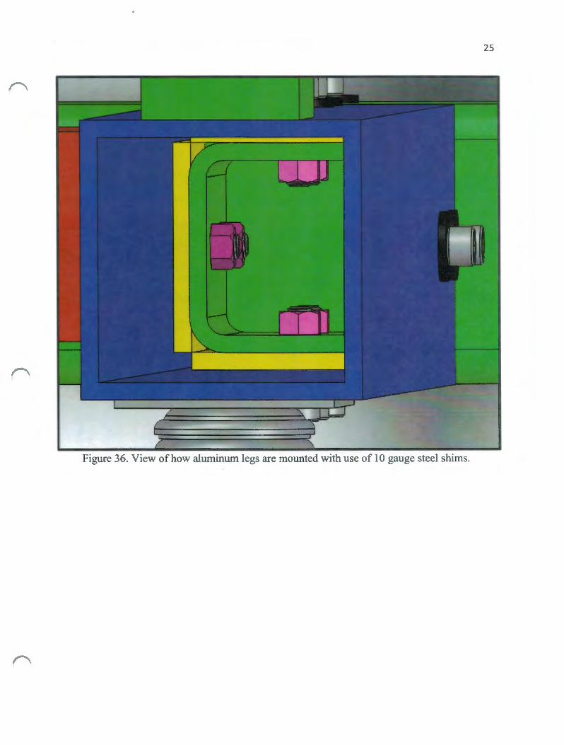
The use of a receiver and shim type setup was designed so the frame can be bolted together while maintaining structural strength. Also, when using a smaller receiver a tube the same size as the main rail can be mounted over the receiver resulting in keeping the design nice and sleek once assembled. Aluminum loses much of its strength capabilities when welded upon, and it is difficult to achieve a proper weld if there are contaminants in the aluminum. In order to avoid these difficulties, the main member was constructed out of steel to in order to make it possible to be welded upon consistently.
The receivers being welded upon the main member need to allow for enough clamping area to be structurally sound. It will be drilled on a mill to ensure proper and accurate hole-spacing. Wall thicknesses and shim sizes were studied before. This ensured that a common 10 gauge plate could be cut to make the shims and leave only a few thousandths of an inch of space between the receiver and attaching tubes. Below figure 33 & 34 demonstrate the receivers welded to the designed main member by the use of a TIG welder.
Figure 33. A rear view of the main frame member.

23
Figure 34. Front view that depicts main frame receiver design.

24
Left and right drive legs. For these left and right drive leg members, the material used will be aluminum, rather than steel. This allows for a lighter overall product weight and these members will not have to endure high temperatures in the way the main frame member will since these members will not endure welding.
Another parameter will be the desired shape of the material. A common 6061 aluminum square tube will have rolled or slightly curved edges. This material was avoided because the inside diameter of the tube does not allow for full usage of the space that is needed when trying to bolt all components within the structure.
It was found that a four-inch square 6063 architectural aluminum has the clearance required to run components internally within the member since the inside diameter is formed by sharp 90 degree angles. This allows the total inside surface of the member to be utilized. The designed drive leg shown below in Figure 35 will slip over the steel receivers with use of shims, which can be seen on the following page in Figure 36.
Figure 35. View ofthe drive tire leg.
25
Figure 36. View ofhow aluminum legs are mounted with use of 10 gauge steel shims.

26
Steering Leg/ Motor & Gear Reduction Leg. The gear reduction box seen in Figure 38 below will be mounted to the aluminum leg shown here with the motor mounted inside. In order to keep the structure's appearance as homogeneous and aesthetically smooth, this leg will not be welded upon. Compared to others, this member will have the highest amount of force applied to it, yet it will be well within its capabilities.
This frame was designed for the goal of incasing all components within the machine, and was not necessarily designed with the most economical safety factor in mind. The main goal of this member is to enable the dolly to be weather resistant, and allows the aircraft to be retrieved or placed outside in many more weather conditions compared to most, such as in the rain.
The four-inch 6063 aluminum tube will be able to incase both the Milwaukee drill motor and the battery. Below Figure 37 displays a rough drawing ofthe steering and motor/gear reduction leg demonstrating how the leg will be bolted to the main frame.
Figure 3 7. Backside of gear reduction box & chain transfer hole to the mainframe axle.

27
Figure 38. View of steering I motor & gear reduction leg.

28
Geometry. As found during the literature review there were an array of geometries to choose from when designing an aircraft dolly, however, the three-tire swivel method was chosen since it allowed all the components to be hidden internally. This choice also allowed the aircraft tire to be placed into the desired position in the center of the frame granting the weight of the aircraft to be more efficiently distributed across the three tires.
The weight will then be distributed much more evenly throughout the structure as seen in Figure 39, 40 & 41. These products often load the aircraft tire immediately over the back two tires due to the space constraints that are caused by their motors and other components. This dolly will allow the weight to be received farther into the overall structure.
Figure 39. Structure of frame allowing an equal distribution of weight.

29
Figure 40. A front view of the aircraft dolly' s deep receptacle capabilities.
Figure 41. Overall view of designed electric aircraft dolly.

30
FABRICATION PROCEDURE
Main Frame Fabrication. The process started with the main frame attachment tube for the drive and swivel legs of the aircraft dolly. This piece is the only member that will be welded or ground. The mild steel member was first cut on a band saw. The access holes were then located on the mill for accuracy in order to help guide the jig saw in creating the chain drive passage ways. Figure 42 displays the mill work followed by Figure 43 displaying the result of cutting the spaces out with the jig saw. This hole was created to be able to clear the needed 11 tooth sprocket height and width of the #35 chain. Additional length and space was added to create a safety factor for alignment issues with the drive tires.
Figure 42. Using mill to drill locate holes for chain routing.
Figure 43. Jig saw and die grinder used to complete chain routing pathways.

31
Next was the cutting and drilling of holes for the mild steel receivers that were welded to the mainframe tube. These receivers accept the aluminum members for both the drive tire tubes and the steering/motor tube. The receivers were carefully sized a half of an inch less than the outside diameter of the mainframe. The use of the specific ten gauge sized shim could therefore, be cut and placed in between to create a tight and secure fit for the aluminum tube.
The tube then slides over to be clamped down with two bolts on each side, making for a total of eight bolts clamping the aluminum member to each receiver piece. It was designed to be a tight fit with only allowing a few thousandths of a gap on each side of the tube. As seen below, Figure 44 depicts this fit and also displays the use of the jig to self-align itself and make the aluminum members both straight and square to the main steel member.
Figure 44. Depiction of how the receivers were squared and tacked into place.
After the above jig was setup for alignment, the receiver was then tack welded onto the inside using a Lincoln 185 TIG welder. The outside aligning materials then were removed and the tube was wire brushed and preheated to ease the welding process. As seen on the following page in Figure 45, the tube was completely welded around the outside diameter with the use of a 1060 mild steel rod. The weld must be thinner than the shims thickness so the aluminum tube can then slip over and fit flush against the mainframe. This allows for an aesthetics as well the maximum use of the receiver mount. See Figure 46 for a depiction of the weld achieving the accurate fit in order to reach the best possible maneuverability.

32
Figure 45. View ofTIG weld attaching the reciever to main frame.
Figure 46. View of fitment of the aluminum leg over the receiver and shims.

The steering and motor receiver differed from that of the drive tire leg receiver in that it was required to be cut out with a jig saw to allow for the tight clearance of the motor. The cutout leaves one inch at the base of the receiver, allowing the welds to the mainframe to still be completely around the outside diameter weld as the others, thus maintaining a large amount of the weld strength. Figure 47 & 48 below depict this cutout and the jig used to once again keep the receiver accurate for the best end results of the aircraft dolly.
Figure 4 7. Steering/motor & gear reduction leg reciever.
Figure 48. Gear reduction to mainframe axle chain routing cutout.
33

34
Steering. Before the rolling chassis was complete, the steering mechanism needed to be built in order to check the clearance for the vertical stabilizer on the test subject aircraft. The goal of the design was to look as though it was floating on the machine with no external or visible bolts holding it together, therefore, it was decided to machine a rod and clevis type steering attachment for the aircraft dolly.
The tight tolerances held between the rod and clevis make for the structure sound enough to handle the moment needed to break traction on the tires. The rod is pressed fit into the steering stem by heating up the chromoly shaft and quickly pounding in. The tube tightened up within seconds of the rod entering due to the thin wall chromoly shrinking very quickly. The piece seen below in Figure 49 adds to the aesthetics of the machine and the stem cannot be removed without cutting the tube down with a lathe. Figure 50 depicts a full view of the completed steering attachment.
Figure 49. Rod and clevis attachment.
Figure 50. Steering attachment complete on rolling chassis.

35
Drive tire/motor & reduction legs. The aluminum members were then cut with the band saw and placed into the mill. The mill was used to accurately locate the holes needed for the bearings mounts as well as the axle pathway as seen in Figure 51 & 52. First three holes were drilled for the bearings and axle, then the axle hole was bored to one-inch. The hole was then reamed out until the adequate clearance was achieved to create a very tight but non galling situation on the tube. The test placement of the bearings and the 22T sprocket ensured all clearances were accurate and achievable.
Figure 51. Drilling axle pathway through drive tire leg.
Figure 52. Drive tire axle assmbly.

36
With all holes and mounts complete, the rolling chassis of the aircraft dolly was assembled and tested for alignment as well as the flexibility of the frame when loaded with the appropriate weight. As seen below in Figure 53 & 54, the rolling chassis was bolted together very smoothly and all tolerances were held properly after welding on the mainframe. The size and geometry of the aircraft mover was also checked and placed next to the test aircraft to start the process of designing and constructing the tire receptacle.
Figure 53. Rolling chassis placed next to aircraft.
Figure 54. View of rolling chassis.

With the above rolling chassis completed and checked for proper sizing, the next step was to work on the drivetrain components. The bearing seen in Figure 55 had the same outside dimensions as the receiver tubes allowing it to slide inside the mainframe tube as well as have room to be tensioned for proper chain function. As seen in Figure 56, thick steel nuts were welded in the radii of the tube comers to accept the bearing bolt pattern. Additional reaming of the bearings had to be performed to produce a square fit. Below is a depiction of the bearing carrier as well as how the face of the bearing is mounted to the carrier.
Figure 55. Bearing placed upon carrier.
Figure 56. Main frame bearing carrier.
37

38
The axle that spans across the main attachment tube was then placed. Below is the axle that receives power from the gear reduction box and sends it down to the drive tire sprockets. The most crucial part of this process was making sure all clearances were acceptable as well as making sure that the chain did not sag into any of the internal parts. Tensioning was possible by the way of two nuts being welded onto the backside of the carrier and were then pulled backwards by bolts in the swivel tire aluminum member. As seen in figure 57 & 58 below, all clearances were found to be acceptable and the chain was tensioned to an acceptable tightness. This allowed for clearance of the internal components while letting the chain travel smoothly.
Figure 57. Main frame axle/sprocket with chain tensioned.
Figure 58. Front side view of chain tensioned.

39
Drill motor. With the drivetrain operational and in need of a powering system, the fitment and fabrication of drive shafts used to convert the drill and run the speed reducer were then conducted. Since the drill didn't originally fit within the inside diameter of the aluminum tube it had to be machined in order to fit the clearance specifications ofless than four-inches. Less than one quarter of an inch had to be removed from the underside of the drill.
The drill motor to the right angle head driveline was then fabricated by simply cutting two sockets in half, and slipping them over the drive nuts on both sides of the components as seen in Figure 59. The shaft that mated the exiting drill head socket to the speed reducer seen in Figure 60 below, was machined from a one-half inch stainless steel shaft and then keyed with a oneeighth inch end mill. Both the socket driveline and the speed reducer shaft were TIG welded with the use of the appropriate filler rod.
Figure 59. Fabricated and welded socket driveshaft.
Figure 60. Machined and welded speed reducer shaft.

40
Drill to speed reduction box mating. The drill head shaft was now able to accept the gear reduction box as seen below in Figure 61. Alignment and mounting of the motor to the reduction box was the next step to further the fabrication process. Once completed it allowed power to reach the drive tires at the proper speed for the moving of an aircraft. The drill and the shaft was then placed through the aluminum tube as seen below in Figure 62, followed by the assembly of the gear reduction box that can also be seen on the following page in Figure 63.
Figure 61. Drill shaft mounted into gear reduction box.
Figure 62. Backside view of drill mounted in frame.


42
Tire Receptacle. The tire receptacle was made with multiple pieces of both steel and aluminum. First three-inch square mild steel tabs had to be welded upon the frame in order to serve as a mounting point for the rest of the scoop. The tabs were then TIG welded. The left side tab is displayed in Figure 64 below.
Figure 64. Mounting tab for scoop welded upon main frame member.
Multiple spots were then drilled into the main aluminum scoop sides. These holes allowed the scoop to be adjusted horizontally for an optimum loading height. A spare mild steel tab and steel shaft were used to ensure accuracy that all bolts fit with minimal play as Figure 65 shows below.
Figure 65. Drilling adjustable scoop side.

The next step was to drill the adjustable aluminum plate outward allowing the scoop to accommodate the different size tire diameters used on the target aircraft. Figure 66 below displays the plate the axle will pivot through.
Figure 66. Adjustable tire plate/ axle pivot plate.
43
The axle was then put into the mill allowing the aluminum ramp to be bolted squarely upon it. Figure 67 below shows the end mill cutting which in turn allowed the ramp to sit flush upon the axle.
Figure 67. End mill cutting flat spot on axle.

44
After tapping the axle for the ramp mounting, the receptacle was then assembled and mounted to the main frame of the dolly. Figure 68 below shows the scoop set at the medium height and at th,e smallest tire diameter setting.
Figure 68. Scoop complete and mounted to main frame.

45
Final Assembly. The machine was now capable of moving with the addition of chain, which ran from the gear reduction box to the main frame axle. The battery was then wired to the motor and then to the Milwaukee stock controller, allowing the powering of the entire aircraft dolly. Figures 69, 70 & 71 below display the final assembly ofthe electric aircraft dolly.
Figure 69. View of the scoop mounted upon completed electric dolly.
Figure 70. Side view of completed electric aircraft dolly.

46
Figure 71. Rear view of completed electric aircraft dolly.

RESULTS
Testing. Once fmal assembly was completed, the aircraft dolly was taken to the Porterville Municipal Airport in order to be tested on an Aviat Husky Al-B tail dragger aircraft as seen in Figure 72 below.
"''"''*•••=•
Figure 72. Electric aircraft dolly placed next to the Aviat Husky.
The unloaded electric aircraft dolly was then driven around to make sute no connections or problems would occur during transportation. It was then placed behind the aircraft as seen in Figure 73 below with all clearances being looked at once again before testing in order to be certain that no damage to either the dolly or the aircraft could occur.
Figure 73. View of completed aircraft dolly placed behind the aircraft.
47

48
The dolly was then ready to receive the rear tire of the aircraft and transport it for the first time as seen in Figure 74 below. It was designed to load an aircraft by simply running the ramp of the dolly into the aircrafts rear tire allowing the aircraft tire to climb up into the dolly' s cradle. Once loaded the tire then sits in between the ramp and axle, resting against the mild steel main frame member as seen in Figure 75 & 76. This approach was very effective with the rear tire of the aircraft rolling as expected into the correct location on the dolly as seen below.
Figure 74. View of rear tire ready to be received into aircraft dolly.
Figure 75. Rear tire of aircraft loaded into dolly receptacle.

Figure 76. Rear view of dolly loaded with aircraft.
The variable speed drill motor was first run at a low speed, and then brought up to full speed once the aircraft began moving. This was done to reduce the stress on all components and allowed for the drill and drivetrain to have a soft start.
49
The dolly moved the aircraft with ease as all drivetrain components functioned smoothly. The dolly had the ability to abruptly stop the aircraft when the drill motor was stopped. This was due to the drill motor and gear reduction box being mated together and working as an integrated braking system. For ease of operation, gradually releasing the throttle was found to be helpful in reducing any possible drivetrain stress. Figure 77 below shows the dolly propelling an aircraft for the first time.
f'
Figure 77. Moving the A viat Husky for the first time with dolly.

Turning the dolly was noted as a possible issue within design, however, due to the fact that the tire receptacle was placed near the center of the dolly's tire footprint it then allowed the weight of the aircraft to be more evenly distributed throughout the structure. This difference makes it easier to turn without the use of a differential. Although dollies are more commonly used to move an aircraft in a straight line when placing the aircrafts in and out of storage sites, if an unexpected situation were to arise such as an obstacle, the dolly would then be able to assist in the navigation around these obstacles. Figures 78 & 79 below show the dolly successfully turning the machine in both a forward and backwards motion.
Figure 78. Turning the aircraft while in forward motion.
Figure 79. Turning the aircraft while in reverse motion.
50

51
After successfully testing the dolly in loading, moving, and the turning of an aircraft, the next function of the dolly was to then test the unloading an aircraft from the receptacle. The method for unloading the dolly required stopping and apply a large amount of throttle in the reverse direction. Due to the aircraft's inertia, this movement forced the rear tire to rise up over the pivot axle and flip the ramp downward, allowing the plane to roll down to the ground smoothly. Once the aircraft was unloaded, it only rolled a foot past the rear tire's initial ground contact location. Figure 80 below shows the aircraft being unloaded from the dolly.
Figure 80. Aircraft position after unloading.
The 28 volt lithium ion battery served as the power source for the drill motor and had proved to meet the required standards. When towing an aircraft out of a hanger and retrieving it once, a 100 feet was measured to be the minimum distance required. On one battery charge, the dolly successfully powered the aircraft over 500 feet. This demonstrated that the dolly can successfully tow and retrieve the aircraft five times without the need to recharge the battery. The factory Milwaukee charging system allows an individual to fully recharge a battery within one hour.
Cost. The total cost of the fmalized aircraft dolly design was in a reasonable price range despite the circumstances of using high quality components that are capable of lasting many years. The components making up the most cost of the dolly were the drill and gear reduction unit followed by the frame members. The drivetrain components, such as bearings, also quickly accumulated into major costs. Although donated components helped to reduce the price, it would most likely be possible to fmd these parts at a reasonable price making it viable to produce another dolly designed the same way at a similar price. The cost of each component as well as the total cost can be found in the table on the following page.

52
Table 5. Cost Breakdown of complete Electric Aircraft Dolly. I D escription on Dolly I Part Callout I # Bought I ft.' bought I M aterial Prov ider I C ost
Motor/Battery/ Milwaukee 28V Right I NA Milivaukee $375.00 Controller/Charger Angle Drill
Gear Reduction Box Amp Flow Gear 1 NA Amp Flow $200.00
Handl:l Bars Carbon Fiber 1- 1/8" 1 NA CCM $129.98 Handlebars
Drivilg Tires Burris Racing Sli::k 2 NA BMl Cart Supplies $114.00 11 "x6"x6"
Receivers/ Bearing 3/8"- 16 Socket head 50 NA McMaster-C arr $89.20 bohs wire te bolt, 1-1/4"
I L & R Drive Legs/ 4"x 4" .125'" \>Van 1 6 McMaster-Carr $77.34
Swivel & Motor Leg 6063 Aumitrum Drivilg Wheels 6" Douglas Q+ 2 NA BMI Cart Supplies $73.90
Al Wheels, Black
Drive Tire A.."Ues Fully keyed Al 1 2'(24") McMaster-Carr $69.52 shaft. 24" x 1 "da.
Ramp plate 3/8" 6061 Aluminum 1 NA Donated $58.67
Mail Frame A-xle Fully keyed Al 1 2'(24'') McMaster-Carr $47.34 Shaft .. 24"x 3/4 Dia
Drive Axle Bearings 2 Bok Flange Unit 4 NA MIEC $46.00 1" shaft Dia.
Main Frame/ Gear #35 Rolbr Chan 4 NA Me1\llaster-Carr $45.12
Reduction Sprocket Sprocket, 11 T, 3/4 '1.0
Man Frame 4'x4".125 wall 1 3 McMaster-Carr $44.60 Carbon Steel
Steering Stem 1- 118" chromoly 4130 1 4" McMaster-Carr $43.74 .065"wall
Dtn--e Tire Sprockets #35 Rolbr Chan 2 NA McMaster-Carr $43.46
Sprocket, 22T, 1" ID
Receivet-sl Bearing 3.5"X3.5 .125 wall 1 3 McMaster-Carr $41.51 Carrier Carbon Steel
Steering Rod and Clevis Machile 7075 Steerng 1 NA CCM $38.59 Clevis & Rod, Dowel
Chan Tensioner # 35 Chain Tensi:mer 1 NA McMaster-C arr $36.48
Snap Stye
Chait #35 Chain 1 10 McMaster-Carr $31.40
Ramp Skid Plate 3/8"UHMW Plate 1 NA CCM S28.65
Man Frame A-xle 4 bolt Flange Unt 2 NA AMEC $21.00
Beatings 3/4" shaft
Wheel Hubs Lightened Al 2 NA BMI Cart Supplies $21.00
Racing Hub
S"vivelwheel 5" Soft Compound 1 NA Fm1 Gmwers $15.00
&Mount S"-.1ve1Ti·e MotorBoks 7/ 16"-14 SS Socket Head 5 NA McMaster-Carr $5 .59
bolt
Washers 3/4" OD 3/8'' Auminum 100 NA McMaster-Can· $4.57
Lighhv-eight Washers
!Total Material Cost $1.701.661

53
Table 6. Labor and Consumable Cost Chart.
Task Time (Hours) Cost of Labor/ Consumables
Frame Fabrication 40 $2,400
Main frame Welding 5 $300
Scoop Fabrication 6 $360
Motor/ Reduction Machining 4 $240
Final Assembly 8 $480
Shop Consumables Estimate {5% of materials) $85
*Estimated Labor Rate of $60/hr. 63 $3,865

54
DISCUSSION
Design. The choice to incorporate as many components internally as possible into the structural frame of the aircraft dolly led to a significant increase in the amount oftime both fabricating and assembling the electric aircraft dolly. With components placed internally within the frame a simple task, such as routing the chain, became a challenge. Another challenge was finding components that would fit inside the structure, however, these challenges needing to be overcome really added to the overall quality of the final product in the end. The sleeker more desirable looks, the reduction of pinch points, as well as the weatherproofing of the dolly without the use of a fiberglass or aluminum shell could possibly make the dolly unique enough to be marketable in the future.
Fabrication. Fabricating with the lack of certain tools for welding the mainframe, such as a jig, added to the time to the overall process. Also, some fabrication steps were taken before others and can now be avoided in the future due to knowledge obtained during this build process. Fabrication of all legs and members were done manually on a mill for accuracy. The actual operations being conducted on the mill was often a mere portion of the time when compared to the amount of time it took to setup for fabrication. Now that a prototype electric aircraft mover is built, the locations and sizes of all operations are readily available. For example, the use of a CNC machine instead of manually performing all labor could be used to cut the fabrication process down. With all parts required to be drilled and programmed into a CNC machine, the dolly could then only require the manual welds to be conducted for the main frame as well as its assembly.
Assembly. The assembly of the electric aircraft dolly was very labor intensive due to the components being contained within the structure as well as its multi-piece frame. Every facet of the machine can be taken apart, which allows possible changes and altercations to occur at any time, however, piecing it all together would still take a fair amount of time. As mentioned above, the simple task of routing a chain proved to be problematic due to it being run inside of the structural frame. Things learned during assembly ranged from only using only certain types of nuts to searching for creative ways to pull the chain through the frame legs. There was a very specific order of operations for both the motor and the gear reduction assembly. The right angle head of the drill had to be bolted at the same time as the reduction box, followed by slipping the drill motor into the frame. The order of operations were learned as the process unfolded. Now that the design for this type of dolly has been completed, a new dolly could be assembled within a fraction of the time.

55
Cost. The cost was slightly higher than predicted, however, high quality components were used, such as billet go kart wheels and hubs. If more dollies were needed to be manufactured, parts such as these could be replaced with cheaper industrial-type components such as wheels and tires, resulting in a reduction of cost. Although some parts were donated, it is very likely that a reduction in overall cost would be viable due to the present knowledge of the price ranges of comparable systems.
Safety. The dolly was calculated to have a structural safety factor of over four to one where the highest loading point occurs in the motor and steering beam. An incident that is not likely, but possible is if the switch or throttle were to become jammed while backing the aircraft into the hanger. If this were to occur the operator could have a chance of being seriously injured or killed by being pinned between a hard surface and front ofthe dolly. There is also the possibility of the aircraft being ran into objects that could either inflict damage to the aircraft or to an individual. Another possibility is if the dolly's wheels were to run over a part of an individual ' s body creating a serious injury. No lock is currently used and with the battery being near to the operator it is currently removable within seconds. A solution for these two possibilities would be to tie a safety tether onto the face of the battery and placing a lever for this action onto the handle bars, creating an emergency shut system. This could help to prevent any unwanted movement of the dolly in an emergency situation.
Overview. Despite using the small components of a hand drill, the battery life and available power was impressive. Not only did the overall performance of the machine meet the objectives of its design, it far surpassed them. Based on the machine's performance during testing, it is highly likely that ifthe electric aircraft dolly were to be produced in an economically feasible way it could therefore, be developed into an extremely desirable product in the near future.

56
RECOMMENDATIONS
In hindsight, the programming of all parts into a computer numerical control machine would be beneficial for the fabrication process due to the amount of time that would be saved. The addition of a steering mount support would also be beneficial for the structural soundness of the machine. Those building this product should use a jig if possible for the main frame member in order to aid in the time frame and accuracy of the final product. The added use of 6061 aluminum in the future would also greatly increase the needed strength if it were to ever carry a larger capacity of weight. It is suggested that those building this product should strive to use a larger amount of industrial type components such as replacing any carbon fiber and chromoly materials with steel, greatly reducing the overall cost of the final product.

REFERENCES
Aviat Husky. 2013. Husky Model Internet Homepage. < http://www.aviataircraft.com/husky.html>, referenced May 20, 2013.
RC Aeronautics for Dodos. 2013. Model Airplane Homepage. <www.modelairplane.cadblog.net>, referenced May 25,2013.
Piper. 2013. Piper Internet Homepage <http://www.piper.com>, referenced April16, 2013.
Star Tribune. 2013. Star Tribune Business Internet Homepage <http://www.startribune.com>, referenced April18, 2013.
Vans Aircraft. 2012. Vans Aircraft Internet Homepage. <http: //www.vansaircraft.com> .referenced May 20, 2013.
Honda Engines. 2013 . Honda Engines Internet Homepage. <http://engines.honda.com>, referenced May 20, 2013.
Briggs and Stratton. 2013. Briggs and Stratton Internet Homepage. <http://www.briggsandstratton.com>, referenced April16, 2013 .
Do It Yourself Go-Carts. 2013 . DIY Go-Carts Internet Homepage. <http://www.diygokarts.com>, referenced April15, 2013
PowerTow. 2013 . PowerTow Internet Homepage. http://www.powertow.com, referenced April28, 2013 .
Mototok. 2013. Mototok Internet Homepage. www.mototok.com, referenced June 1, 2013.
Priceless Aviation Products. 2013 . Priceless Aviation Company Internet Homepage. < http://pricelessaviation.com>, referenced may 4, 2013 .
AC Air Technology. 2013. AC air Technology Company Internet Homepage. <https://www.acairtechnology.com>, referenced April15, 2013.
Versa Tow Airplane Tug. 2013. Versa Tow Company Internet Homepage. <http://www.versa-tow.com/>, referenced may 4, 2013.
57

Trace Tow Bots. 2013. Trace Tow Bots Internet Homepage. < http: //www.tracetowbots.com/>, referenced May 16, 2013 .
Redline Aviation. 2013. Redline Aviation Company Homepage. <http: //www.redlineaviation.com/>, referenced May 20, 2013.
DRAGGER Aircraft Tug. Dragger Aircraft Internet Homepage. < http://dragger.com/>, referenced May 18, 2013.
Wings and Wheels, 2013. Wings and Wheels Company Internet Homepage. <http://www.wingsandwheels.com>, referenced May 4 ,2013.
SmartTug. 2013. Smart Tug Company Internet Homepage. <http: //smartug.com/>, referenced May 18, 2013.
Mcmastercarr. 2013. McMastercarr Internet Homepage. <http://mcmastercarrr.com />, referenced June 9, 2014.
Ampflow. 2014. Amp Flow Internet Homepage. <http://ampflow.com />, referenced May 12, 2014.
Amec 2014. Amec Industires Internet Homepage. <http://amecind.com />, refenced April15, 2014.
Milwaukee Tools. 2014. Milwaukee Tools Internet Homepage. <http://milwaukeetool.com/>, referenced May 16, 2014.
58

S11:JIGN11ddV
65

09
liOfVW WSV m~ liO.tl S~N:tiWIDllilOJrn S~:tl:tiW ~:>:tlfOlld m~ MOH
V XI<IN:tlddV

ASM Project Requirements
The ASM senior project must include a problem solving experience that incorporate the application of technology and the organizational skills of business and management, and quantitative, analytical problem solving. This project addresses these issues as follows.
61
Application of Agricultural Technology. The project will involve fabrication technologies, DC electric motor, and powertrain technologies.
Application of Business and/or Management Skills. The project will include business/ management skills in the areas of cost and productivity analyses, labor considerations, as well as fabrication management.
Quantitative, Analytical Problem Solving. Quantitative problem solving will include speed and power calculations as well as a material cost analysis.
Capstone Project Experience .The ASM senior project must incorporate knowledge and skills acquired in earlier coursework (Major, Support and/or GE courses).
• BRAE 129 Lab Skills/Safety, • BRAE 133 Engineering Graphics • BRAE 151 CAD for Agricultural Engineering • BRAE 203 Agricultural Systems Analysis • BRAE 321 Agricultural Safety • BRAE 342 Agricultural Materials • BRAE 343 Mechanical Systems Analysis • BRAE 418 Agricultural Systems Management I • BRAE 419 Agricultural Systems Management II
ASM Approach. Agricultural Systems Management involves the development of solutions to technological, business or management problems associated with agricultural or related industries. A systems approach, interdisciplinary experience, and agricultural training in specialized areas are common features of this type of problem solving.
Systems Approach. The project involves multiple systems including analysis and fabrication of frame, integrating motor into frame, and building drive and steering system to provide pilots with an efficient system to transport aircraft in and out of hangar.
Interdisciplinary Features. This project involves the fields of mechanical systems, agricultural safety, lab skills and safety, and agriculture materials.
Specialized Agricultural Knowledge. The project will involve and require special knowledge in the fabrication n of mechanical systems, lab skills and safety.

zg
SNOI~Vrul::>'IV::> N~IS:IG
HXIGN:IddV

Speed/Gear Reduction Calculations
Given: Drill output RPM=1000
Drive tire size= 11.5"
Required: Design a gear reduction system to propel the electric aircraft dolly at 3 feet/ second while only have two stages of sprocket reduction.
Solution: Size of sprockets needed to reach required reduction in two stages doesn't fit within size constraints of main frame. Therefore, gear reduction box is required.
Tire diameter= 11.5'' (11.5'' x 3.14= 36.11") circumference or 3.009 feet/second
Need to rotate this size tire once per second to achieve 3 feet per second
Decided upon an 8.3:1 reduction box Drill RPM/ Gear Reduction Box Ratio = Output RPM on Reduction Box Shaft
lOOO(Drill RPM)/ 8.3= 120.48RPM of Reduction Box Output Shaft
Twice the desired RPM of drive tire, therefore need to reduce further at 2:1 ratio 26T 1" sprocket is the largest that fits within 4" aluminum drive tire leg. 13T sprocket used on output shaft and main frame axle will achieve 60RPM
63
11 T sprocket available for output shaft and main frame axle sprockets, therefore chosen to leave more clearance within frame for chain. 22T now needed for drive tire axle.
Gear Reduction Box ratio * Further gear reduction ratio= Final gear reduction
Further gear reduction ratio= 22T/11 T= 2:1 Reduction Ratio
Final Gear Reduction = 8.3 * 2.0= 16.6:1 = Final Gear Reduction
Test Calculations for desired 60RPM of drive tire.
Drill RPM/ Final Gear Reduction= Drive Tire RPM
1000/ 16.6= 60.24RPM
Rotation per second= RPM/60 seconds
60.24RPM/ 60 seconds= 1.004 Rotations per second
Feet per second of drive tire= (Rotations per second)*(Tire Circumference)
Therefore 1.004(Rotations/Second) * 3.009 ' (Tire Circumference) = 3.02'/second
Fil)al Calculated Dolly: Speed= 3.02 'I Secon
Final Gear Reduction Ration= 16.6:

Torgue Calculations
Given: Drill motor output torque 1 OOOin/lbs @ 1 OOORPM
Required: Find final torque that dolly produces at drive tires after reduction.
Solution: Output Torque= Input Torque x Ratio of Gear Reduction
Torque for this situation is measure in inch pounds
Output Speed= Input Speed/ Ratio of Gear Reduction
"
64
Calculations: Output Torque = 1000 inch pounds (input torgue) x 16.6 (Ratio of Gear Reduction)
~16,600 inch oounds of toraue
Output Speed = 1000RPM (Input Speed)/ 16.6 (Ratio of Gear Reduction)
E..60J.lliPM@ Drive Tires

Frame Calculations
Given: 128 pound load placed on dolly. Required: Find highest bending moment Solution:
1281bs
t4" ""····'/
•
f 35" "0
~4"
12 I")~ II 23
M=P * f
M = 128 lbs * 15"
M = 1920 in - lbs
65
f
15"
•

S- Value required Calculations:
Actual S-Value Calculations:
Hollow Rectangular
Axis of moments through center
SCM 17-37
Mmax sreq =ra
1920 in -lbs s - -------req - 9600 psi * (16000 * .6)L·SF
6d3- 613 s = 6d
(4 X 43)- (3.75 X 3.753 ) S=--------
6x4
256- 197.753 S=-----
24
S = 2.42 in3
66
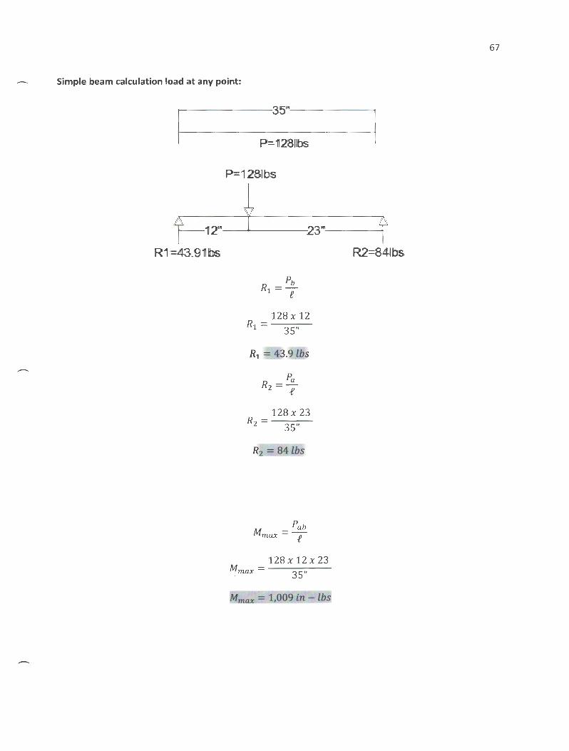
Simple beam calculation load at any point:
r----------_:.:3:5'"·------------t
P= 128,11bs.
P=11283bs
.l ~12'" y 23'" f
IR 1 =4r3,_9'1llbs. R2=8·4111 bs
pb R1=f
128 X 12 Rl = 35"
Pa Rz =e
128 X 23 Rz = 35"
R2 = 84lbs
Pab Mmax =T
128 X 12 X 23 Mmax = 35"
Mmax = 1,009 in - lbs
67

89
SDNIM.Vll<I~HVd
=> XI<IN:ilddV

Design and Fabrication of an Electric Aircraft Dolly
(AIRCRAFT DOLLY ASSEMBLY AND PART DRAWINGS)
NOTE: All scales vary in each part drawings. Refer to report for fabrication and assembly details.
5
Sheet Name
• Part Details • Frame Assembly • Main Frame • Bearing Spacer • Bearing Spacer Shim • Frame Shim • Mounted Bearing (Square) • Drive Shaft • Frame Support • Mounted Bearing • Wheel Shaft • Steering Support • Steering Handle • Steering Handle Connector
4 3
I Sheet Number
A-1.00 A-1 .01 A-1.1 0 A-1.11 A-1.12 A-1.13 A-1.14 A-1.15 A-1.20 A-1.21 A-1.22 A-1.30 A-1.40 A-1.41
2
Designer:
KYLER ZIKE
-. ~ ~ ....
~ 0 ,....c ~ ,....c 0 ....,
= ~ 0 ~
~ ¢:: ~
~ ~
~ u ~
~ . ...
~ < u ·- ....
< ~ .... u ~ -~ ...._,
1r CLASS:
Senior Project BRAE 462
Title Page
SHEET:
T -1.00

Main Frame Sheet A-1 . 1 0
Frame Support Sheet A-1.20
Steering Support Sheet A-1 .30
Steering Handle Sheet A-1 .40
Steering Hand le Connector Sheet A-1 .41
Drive Shaft Sheet A-1.15
DETAIL E SCALE 1 : 5
Wheel Shaft Sheet A-1.22
Mounted Bearing Sheet A-1.21
Frame Shims Sheet A-1 . 13 Bearing Spacer Sheet A-1 .11
Mounted bearing Square Sheet A-1 .14
Designer :
KYLER ZIKE
,.-.._ .. ~
~ .... 0
~ ~ ~
0 ..... -~ -0 ~
~ .;;:: eo:
~ .. - CJ
rJ ~ - CJ ·~ ..... < .::
CJ ~ -[5
CLASS :
Senior Project BRAE 462
Bearing Spacer Shim I,.------------Sheet A-1 . 12
Part Details
Note: Wheels, Sprockets, Chain Type, and Power source Specified
Detail- D A-1.00
in rep?~+ ----------.:------------r-------\
5 4 3 2

(or) "<;;j
~
().,
5
20"
• •
20"
Isometric View
Steerin ort Sheet A-1 .30
Main Frame Sheet A-1 .1 0 ().,
• • Frame Supports Sheet A-1.20
4 3
0 ('\J
• •
2
Designer:
KYLER ZIKE
--. ""' <!) ...
~ 0 ~ ~ ~ ..... 0
== ~ 0 ~
~ ¢:: ~
~ ""' C,j
~ ""' ~ < ~ C,j .... .,.... ""' < ...... C,j <!) -e
CLASS:
Senior Project BRAE 462
Frame Assembly
A-1.01

2011
311 1311 1/211 I. 311
~~ i frlj ( frnl11
N ..........
N ..........
8 1 /211 ' 311
' 8 1 /211
~
0
fi Q0.39in
I. I. 311
I DETAIL A SCALE 1 : 5
5 4 3
Isometric View
N
411
2
Designer:
KYLER ZIKE
"i:'
~ ~ ... 0
:;s ~
0 ~ c:: ~ .. ~ .. ·~ <
8 0 ~ ~ ~
'"' ~ '"' < ~ .... '"' ... ~ ~ -~
CLASS:
Senior Project BRAE 462
Main Frame
SHEET:
A-1.1 0

N .......... .---.---
I C'f)
0-:>
411
211 211
(/)0.39in
Isometric View II
r 4" ,-... >
311 II
v: '\
-$- 0-:>
\._
Designer:
KYLER ZIKE
..-,
"" QJ
~ ... 0 _. ~ _.
0 ...... -~ -0 Q
~ ~ ~ = "" ,.... ~
"" ~ .... < ,.... ~ •• . ...
< "" .... ~ QJ -5
CLASS:
Senior Project BRAE 462
Bearing Spacer
SHEET:
A-1.11 Thursday, June 12. 201~~
4 3 I 2 I 5

C'\J -....-....-
(0
4"
2"
\Z) 0.39ir
Isometric View I I
_ 4" ------,j.l 3b) 3" ..
I : ! : I I
Designer:
KYLER ZIKE
-'"" Q,j
~ > 0
~ ,.....c ,.....c Q ...... -~ -0
~
~ ¢::: ~ = '"" - u
~ ~ - u ·~ ·-< '"" ... u
Q,j -~ CLASS:
Senior Project BRAE 462
B ear ing Spacer Shim
SHEET:
A-1.12 1 nursaay. June 1 L. LU 14 '===(
5 4 3 I 2 I
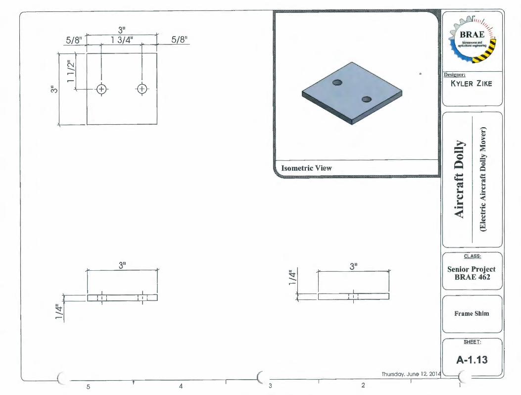
311
l 3/411
('() -$-
Isometric View
311
~l ---'---r-.1..___
~~ r 3"
kl ~.-----J I
5 4 3 2
•
a ~
0 ~ ~ ~ -u -•JIIIIIIIC
<
"i:' ~ .... 0
~ .... = 0 Q ct: d ;... C,j ;...
< C,j .... !: C,j ~ g
CLASS:
Senior Project BRAE 462
Frame Shim

::0 .--.......... 1"-.
c C"l 1"-.
0 ::0 .--.......... l()
C/J 7 I 16"
" 3 _3~/ 8=--" _----.J.-
1
\ ~
I
3 3/8"
I
Co .......... (")
~~ Ill II J ,..,., h ITT - ~ v;
~ .......... (")
B
5 4 3
Isometric View
l.47in
~ .--
..._
L__
2
Designer :
KYLER ZIKE
~
~ ~
> 0
~ --c Q ~ ~ ~ ~ u ~ ·~ <
8 0 Q ¢:: ~ :... e.J :...
< e.J ..... :... ..... e.J ~ -e
CLASS:
Senior Project BRAE 462
Mounted Bearing (Square)
SHEET:
A-1.14

\
Co -1 II II Ill 181
Isometric View II
R3/B" ~
5 4 3 2
Designer:
KYLER ZIKE
I ,-... .. ~
~ ~ 0
~ ~ ~
0 :S ~ 0
~
~ it: ~
~ .. (.J - ·= ~ < - (.J
·~ ..... < .. .....
(.J ~ -~
CLASS:
Senior Project BRAE 462
Drive Shaft
A-1.15

20"
l 5/8" l l /2"
~ <tr
00.39in
Isometric View II
• II
20" 4" -
l I 'I ~~o
5 4 3 2
Designer:
KYLER ZIKE
,-..,
"" ~ ~
.... 0 ...... ~ ......
0 ........
~ = 0 ~
4:::: 4:::: eo:
~ "" J. CJ
"" ~ .... < J. CJ ....... . ...
< "" ...... CJ ~ -~ '-"
CLASS:
Senior Project BRAE 462
Frame Supports
A-1.20

Cx:> --.;;j
w :.::= N ~
r _J
>-· ~ ., ~
-
r--
• r--
'-----
L!69'b
u8/ L L
{.I<lAOW AfiOG lJlUJ.IJV JJ.IP<li:t[)
AUO(I lJg.I~.IJV
.... ~N
...... 1.0 ~
~I 8~ "00.1)
i C\1 ~ =
~~ .... ·-= -= <:<:! ~ Q~ I ~~ <( s:q:~
<1,)
00
l uV/ L 0 l t_g N
~ ........... C'0
B-
uV/L 0
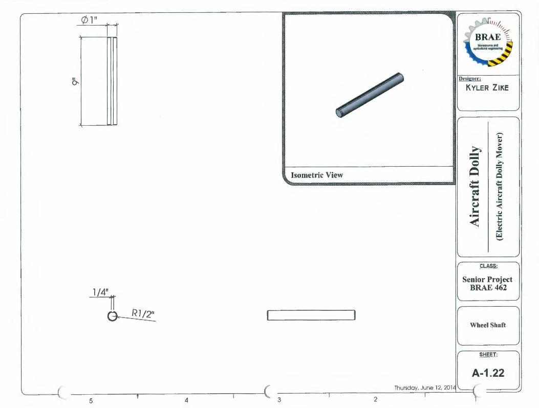
0-
(/) 111
n
Isometric View II
l /4"
~ I I
Designer:
KYLER ZIKE
..-"" Q,j
~ ~ 0
~ _. _. 0 ...... -~ -0
~
i!: 4:::: eo=
~ "" ~ ~
"" ~ < ~ ~
·~ .... < "" ....
~ Q,j -e:t
CLASS:
Senior Project BRAE 462
Wheel Shaft
SHEET:
A-1.22 Thursday. June 12, 2014 \------i
5 4 3 I 2 I

19" I l /4" l 3/4"
.-
~ -$- -$-
f--
I. 3''
Isometric View
l l /4" l 3/4"
N ~ .--- --$- -$- ~
N
l 3"
5 4 3
II
4" n D
2
Designer:
KYLER ZIKE
-,... ~ ~
> 0
~ ,..... ,..... 0 >..
~ = 0 ~
~ ¢:: ~ = ,...
~ CJ ,...
eJ .... <
~ CJ ·~ .... < ,... ..
CJ ~ -~
'-"
CLASS:
Senior Project BRAE 462
Steering Support
SHEET:
A-1.30

0 (")
c ('\J (")
w ~
N ~
r ...J >-
· ~ ., ~
1- I. U!99' l (/)
{.IaAO:W AflOG lJlUJ.I!V Jppa]:i)
~I A:noa lJ~J:JJ:!V
~ c
J Q.l ('\J ..... > (")
~ .... B ""' ....
Q.l
8 0
"' ~
.... <II
~M :a • ....,I.e = 0 e~ <:<:1
i ~ ~~ = . 1:\f) or-= I 'i: <C ~~ <II <II ......
00. IJJ
j_
, u't70
u't70
l[)
L_
JJ U!99' l (/)

2 l /4"
1 I 4" L. 1 3 ~ 4" J - I-
f--
(\-') - -I- --f--
- 1-
l /4"
l l - r-
- I-
~ -- f--......... -- 1- --..-- -- f--
(\-') N
~ ......... C")
w 5 4 3
Isometric View II
~' 1' '
(\-') ~ -------------------
c-J. 3" .l
2
Designer:
KYLER ZIKE
'i:' Q,j
~ > 0
~ ~ ~ Q ::S ~ 0
~
it: ¢:: ~
~ '"' CJ ~ '"' ~
..... <
~ CJ •• . .... < '"' -CJ
Q,j -e
CLASS:
Senior Project BRAE 462
Steering Handle Connector
SHEET:
A-1.41