by Justin Lebowsky
188
Drivetrain Design for the 2016 Global Formula Racing Combustion Car by Justin Lebowsky A THESIS submitted to Oregon State University Honors College in partial fulfillment of the requirements for the degree of Honors Baccalaureate of Science in Mechanical Engineering (Honors Associate) Presented June 1, 2016 Commencement June 2016
Transcript of by Justin Lebowsky

Drivetrain Design for the 2016 Global Formula Racing Combustion Car
by Justin Lebowsky
A THESIS
submitted to
Oregon State University
Honors College
in partial fulfillment of the requirements for the
degree of
Honors Baccalaureate of Science in Mechanical Engineering (Honors Associate)
Presented June 1, 2016 Commencement June 2016

Table of Contents 0. Abstract 1. Project Description 1.1 Introduction 1.2 Rules and Constraint Analysis 1.3 Requirements 2. Current State Analysis and Benchmarking 2.1 Current State Analysis 2.2 Benchmarking 3. Design Analysis 3.1 Sub Section 1 3.2 Sub Section 2 4. Design Selected 4.1 Rationale for Selection 4.2 Technical Specification 4.3 Manufacturing Plan 5. Implementation 5.1 Sub Section 1 5.1.1 Sub Sub Section 1 5.2 Sub Section 2 5.2.1 Sub Sub Section 2 6. Testing 6.1 Tests Complete to Date 6.2 Tests to Complete 7. Conclusion 7.1 Sub Section 1 7.2 Sub Secton 2 8. Works Cited
1

0. Abstract The purpose of this project was to design the 2016 combustion car drivetrain for Global Formula Racing (GFR). The goal of this project was to improve upon the 2015 drivetrain design by reducing complexity, weight, and maintenance time. To reduce complexity the spool was changed to a one piece system and the drivetrain inserts were changed to a simpler design. These changes were able to reduce weight and the complexity of machining by making the designs more simple. The drivetrain mounting system had its complexity reduced by moving to a eccentric chain tensioning design. This was chosen because it reduced the time to adjust the chain and reduced the overall part count of the system. The major issues that occurred during this project had to do with the manufacturing of the drivetrain mounts. Since there were issues finding sponsors to make the mounts they had to be made in house. This required learning edgecam and the cnc machining process to be able to manufacture them. The machining of the mounts took a tremendous amount of time and this made it difficult for their to be enough time during the manufacturing phase to make two complete sets. The result of this project is a finished and functioning drivetrain for the 2016 combustion car. The car has been through numerous test days and the drivetrain has worked exactly as expected. So far there have been no issues with the performance or maintenance of the system. Next year the designer of the drivetrain should focus on further improvement of the spool design and reducing the manufacturing time of the whole system. Furthermore, a heavy emphasis should be put on finding sponsors with large machining capabilities to help manufacture the drivetrain system. Table 1
Part Name Weight (kg)
Quantity Supplier
Spool 0.828 2 MTU
Left Mount 0.428 2 OSU
Right Mount 0.319 2 OSU
Left Clamp 0.138 2 OSU
Right Clamp 0.064 2 OSU
Left Eccentric 0.292 2 Palotov Racing
2

Right Eccentric 0.153 2 Palotov Racing
Spacers 0.024 8 OSU
Spool Plug Housing 0.013 4 RED
Plug 0.018 12 OSU
Halfshaft 0.673 4 Taylor Race
Halfshaft Spring 0.009 4 McMaster Carr
Upper Engine Bolt 0.0383 2 OSU
Lower Engine Bolt 0.106 2 OSU
Crossmember 0.002 2 OSU
1. Project Description
1.1 Introduction
Global Formula Racing is a partnership between Oregon State University and DHBW Ravensburg that competes in the Formula SAE competition. The competition consists of static events which include three different presentations about design, cost, and business aspect of the vehicle. There are also dynamic events that include the skidpad, acceleration, autocross, endurance, and fuel economy. This partnership has had great success at these competitions by focusing on the events that can earn the team the most points. This can be contributed in part to the GFR design philosophy. This philosophy states that we should design the car to win competition(earn the most points), and to win the competition we must design products that are simple, reliable and have their simulations be validated by physical testing. To be successful we must consider this philosophy with every design decision that is made. This includes decisions to prioritize improving parts of the car that are most point sensitive. One project that is considered point sensitive enough to prioritize as a senior project is the drivetrain design. The drivetrain is the area of the car that converts the power the engine creates into power that will spin the wheels of the car. The deliverables for this project is a drivetrain system that helps the team win the competition. A design will help the team win the competition by being lightweight, reliable design that improves upon the design used for the 2015 design. Last year’s approach to this was to transition from a differential to a spool based drivetrain to reduce the weight of the car, the cost of the car, and the part count of the car. In 2014 motec data was taken using a locked and unlocked
3

setting for the drexler limited slip differential, and it was shown that the car would actually record faster lap times on an autocross course in a locked system due to reduced tire slip and the ability to accelerate out of corners faster.
Figure 1: Wheel slip data from testing of 2014 car.
Figure 2: Layout of throttle and braking during autocross track (2014 car). This year the approach is to continue improving on the spool design from last year and see if there are ways to make the design have more efficient energy transfer to the
4

wheels, and have a reduced weight while still being reliable. Reliability is one of the most important factors for this part of the car because without the drivetrain the car will not run. That fact alone makes this project relevant and significant to the GFR team. The benefits to the team when the project is completed would include weight savings and improved efficiency of power transfer, which would result in cost savings and improved performance in dynamic events, which would result in more points earned at competitions. 1.2 Rules and Constraint Analysis There are rules and constraints put on the drivetrain system by the society of automotive engineers (SAE) and by the team that are explicitly defined and assessed for impact on the design in this portion of the paper. Rules that affect the drivetrain design can be found in part T, article 8 which are the technical requirements for the powertrain [1]. [T8.3]: Transmission and Drive
Any transmission and drivetrain may be used. This rule states that there are no limitations on the choice of drivetrain meaning the subsystem is not limited by this rule. Therefore, a drivetrain design can be chosen based off of whichever design will perform the best and earn the most points at competition. [T8.4]: Drive Train Shields and Guards
[T8.4.1]: Exposed highspeed final drivetrain equipment such as Continuously Variable Transmissions (CVTs), sprockets, gears, pulleys, torque converters, clutches, belt drives, clutch drives and electric motors, must be fitted with scatter shields in case of failure. The final drivetrain shield must cover the chain or belt from the drive sprocket to the driven sprocket/chain wheel/belt or pulley. The final drivetrain shield must start and end parallel to the lowest point of the chain wheel/belt/pulley. (See figure below) Body panels or other existing covers are not acceptable unless constructed from approved materials per T8.4.3 or T8.4.4. Note: If equipped, the engine drive sprocket cover may be used as part of the scatter shield system. This rule requires us to design a shield to cover the chain that sends power to the drivetrain. This is a safety parameter that will end up adding weight to the car. Based off of a table equating design parameters to points the chain guard will lose the team 1.51.97 points per kilogram [2].
5

Figure 3 [T8.4.2] Perforated material may not be used for the construction of scatter shields. Limiting the scatter shields to nonperforated materials means that the ability to reduce the weight of the shield is limited and restricts airflow. This, however, has not proven to be a significant factor in past designs. [T8.4.3] Chain Drive Scatter shields for chains must be made of at least 2.66 mm (0.105 inch) steel (no alternatives are allowed), and have a minimum width equal to three (3) times the width of the chain. The guard must be centered along the center of the chain and remain aligned with the chain under all conditions. The 2016 cCar will use a drivetrain this year so a chain guard meeting these requirements has to be implemented. The specific limitations on the shield will result in increased weight of the vehicle so designing the shield to come as close to the minimum requirements as possible will maximize the point earning potential of the car. [T8.4.5] Attachment Fasteners All fasteners attaching scatter shields and guards must be a minimum 6mm Metric Grade 8.8 (1/4 inch SAE Grade 5) or stronger. Similar to the scatter shield rules this rule defines the design of the fasteners for the drivetrain. [T8.4.6] Finger Guards – Finger guards are required to cover any drivetrain parts that spin while the car is stationary with the engine running. Finger guards may be made of lighter material, sufficient to resist finger forces. Mesh or perforated material may be used but must prevent the passage of a 12 mm (1/2 inch) diameter object through the guard. Comment: Finger guards are intended to prevent finger intrusion into rotating equipment
6

while the vehicle is at rest. The drivetrain is not expected to have any rotating parts while the car is at rest but this rule should be noted and considered in case that choice changes at any point during the design process. [T11.1] Fastener Grade Requirements [T11.1.1] All threaded fasteners utilized in the driver’s cell structure, and the steering, braking, driver’s harness and suspension systems must meet or exceed, SAE Grade 5, Metric Grade 8.8 and/or AN/MS specifications. Despite the drivetrain not being mentioned in this rule the loads on the drivetrain are significant enough that all fasteners used on the drivetrain should meet or exceed the standards stated above. [T11.2] Securing Fasteners [T11.2.1] All critical bolt, nuts, and other fasteners on the steering, braking, driver’s harness, and suspension must be secured from unintentional loosening by the use of positive locking mechanisms. Positive locking mechanisms are defined as those that: a. The Technical Inspectors (and the team members) are able to see that the device/system is in place, i.e. it is visible. b. The “positive locking mechanism” does not rely on the clamping force to apply the “locking” or antivibration feature. In other words, if it loosens a bit, it still prevents the nut or bolt coming completely loose. Positive locking mechanisms include: a. Correctly installed safety wiring b. Cotter pins c. Nylon lock nuts (Except in high temperature locations where nylon could fail approximately 80 degrees Celsius or above) d. Prevailing torque lock nuts NOTE: Lock washers, bolts with nylon patches and thread locking compounds, e.g. Loctite®, DO NOT meet the positive locking requirement. T11.2.2 There must be a minimum of two (2) full threads projecting from any lock nut. Even though the drivetrain is not mentioned in this rule it should be considered because the 2015 cCar used positive locking mechanisms on their drivetrain and are being considered for the 2016 cCar as well. Despite it not being required it will make the technical inspectors job easier and will make sure that the subsystem does not come apart during events. Additional Rules that Affect the Drivetrain
7

T1.2.2 is a rule that lists out the parts of the car that are allowed to be altered after technical inspection. There is one rule that affects the drivetrain. a. Adjustment of belts, chains and clutches. Due to the chain stretching during use the drivetrain mounting system must be able to adjust so that the chain is at the preferred tension. The 2015 cCar used turnbuckles on the diff plates to adjust the drivetrain. This method did work but other methods that are lighter or more consistent may replace the turnbuckle on the 2016 cCar. Note: Since sprockets are not mentioned as something that can be adjusted or swapped out the sprocket cannot be changed after technical inspection. This means that a sprocket must be chosen out of our available sprockets prior to technical inspection. External Requirements The external requirements that will affect the design of the drivetrain are size, cost and weight. Since the drivetrain mounts to the engine case the size and weight of the drivetrain will affect the engine case directly so minimizing the forces that the drivetrain distributes to the engine case is a design requirement. Also, the drivetrain interfaces with the chassis and suspension. Since the engine and wheel locations are set, the drivetrain must be designed around those spatial constraints while maximizing the efficiency of power transfer to the spindles. Furthermore, a hole must be cut through the chassis to let the drivetrain mount to the engine case so the size of the drivetrain and the drivetrain mount must be communicated to the chassis team so that the car comes together correctly. Finally, the design is required to be manufacturable either by a sponsor, free of charge, or in the Oregon State University machine shop.
1.3 Requirements Project Summary: Design, manufacture and integrate a spool drivetrain into the 2016 cCar. The deliverables for this project include the spool, drive axles, chain tensioner, spool mount plates and sprockets with spares of everything. The goal of this project is to make the drivetrain lighter and more efficient to increase the point potential of the 2016 cCar. Team Requirements The team requirements and other information pertaining to team dynamics and potential barriers the team might encounter can be found here: The parts of the charter pertaining to team requirements are below:
8
Group Goals
Design and manufacture the suspension system for the 2016 formula race car.
Design and build with the goal of maximizing points for the competition.
Work as a team, sharing and documenting information for others to benefit from.
Keep good communication with other teams and international counterparts.
Group Ground Rules
General
Keep good communication and ask questions as soon as problems arise. Be prepared and well rehearsed for all presentations. Work as a strong unit where all opinions are valued and responsibility is shared. Meetings
Keep our Google calendars up to date. Be punctual and prepared for meetings. Record all meeting notes in our design notebooks. Take meeting minutes and keep track of assigned tasks. Treat these meetings as business meetings and avoid personal/irrelevant conversation.
Respond within 24 hours Keep emails formal Use attachments when necessary to explain a concept. Reply to all suspension team members to keep everyone informed. Use clear and concise vocab Do not hesitate to ask questions when something in an email is unclear
Discussions and Decisions
Be respectful of everyone’s opinions All opinions will be considered Decisions will be made by majority rules Everyone should communicate their opinion when applicable
9

Project Work
Help other teammates if they are behind schedule Meet or beat all deadlines Distribute group tasks accordingly and fairly Effective collaboration will be used to complete all reports and presentations Utilize resources and other SAE Formula members Clearly communicate project task requirements to other team members Improve communication with international team Communicate when help from teammates is needed Offer help to teammates when you have extra free time Communicate design results to subteams affected by them
2. Current State Analysis and Benchmarking
2.1 Current State Analysis Sprocket General Overview: The sprocket interfaces with the spool and the drive chain. Size and tooth count of the sprocket will influence the acceleration of the car and the transitions between the gears of the transmission during dynamic events. How it Works: Sprockets take the linear force from the drive chain and produce rotational energy to spin the spool. The diameter of the sprocket helps produce a moment arm to produce the torque on the spool. What was Used: The 2015 cCar used the 42 tooth sprocket. This is the same sprocket that was used in the 2014 car. In 2014 a 44 tooth sprocket was also considered. It was considered because using a 44 tooth sprocket would result in being able to start the acceleration event from 2nd gear and get to 5th gear by the end of the run. This could be considered again for the 2016 cCar. SWOT Analysis: Strengths:Reliable, lightweight, easily tuned
10

Weaknesses: Tooth wear Opportunities: Make sprocket lighter, make sprocket larger for larger moment arm Threat: Difficult to fit chain guard, failure if part is not strong enough Results: The current design works well. The implementation of shoulder bolts was an improvement to using only bolts like the 2014 cCcar.
Figure 4: CAD model of 2015 spool design from 2015 Drivetrain Report [3]. 5.1.3.1 ‐ 42 T Sprocket
11

Figure 5: 2015 cCar sprocket from 2015 Drivetrain Report [3]. Spool General Overview: The spool is a type of locked differential. It connects the two axles directly to the ring gear and is used in certain competition vehicles that do not need the complexity of a differential to turn the car effectively. This is because competition vehicles do not need to vary the speeds of the back two wheels to maintain control of the car through curves. How it Works: The rotational energy from the sprocket is transferred into the spool to cause it to spin. There are steel inserts at the end of the spool that the constant velocity (CV) joints are
12

housed in, these joints turn with the spool to turn the halfshaft, and consequently the wheels of the car. What was Used: A custom made spool was designed by Jeff Sprenger and consisted of two pieces that were manufactured by MTU out of 7075T6 aluminum. The inserts that were used for the CV joint housing were made out of 4340 steel and manufactured by JeldWen and heat treated by Stack Metallurgical. Further details on this spool can be found in the 2015 drivetrain report [3]. SWOT Analysis: Strengths: Reliable, relatively lightweight, relatively simple design, backwards compatible with Drexler drivetrain from the 2014 car Weaknesses: Overbuilt, complicated manufacturing process, part count has room to be reduced, large moment of inertia (relatively speaking the part count and moment of inertia are low when compared to the 2014 Drexler setup but further improvements can be made) Opportunities: Make the spool lighter, simpler design/manufacturing process Threats: Failure if the part is not strong enough Results: The spool drivetrain that was introduced last year had positive results and improved the performance of the car but was overbuilt to guarantee a high reliability. This year there is room to cut weight on the design and make it simpler since the limiting factor of being backwards compatible with the Drexler differential is no longer a design requirement.
13

Figure 6: Spool inserts
14

Figure 7: CAD model of 2015 spool design from 2015 Drivetrain Report [3]. Halfshafts General Overview: Halfshafts are what connect the spool to the spindle. They are steel shafts with bearing tripods at both ends. These tripods are CV joints that allow the spindles and the spool to be at an angle from each other during operation. The CV joints also keep a constant velocity so that the rotation of the spindles matches the spool. How it Works: The halfshaft rotates with the rotation of the spool and transfers the rotation to the spindles that will turn that rotation into the wheels spinning. What was Used: Halfshafts were made out of 4130 steel by RCV Performance and were electroless nickle plated in Portland. SWOT Analysis: Strengths: Strong, Reliable Weaknesses: Problems with vendor meeting time constraints, heavy Opportunities: Could be made lighter, Could be made out of alternate material (Carbon Fiber could be considered), halfshaft angle could be improved Threats: Failure if part is not strong enough, packaging issues with different halfshaft angle
15

Results: The current design works well but issues with vendors meeting time constraints means that new vendors should be considered. The design could also have the manufacturing process simplified if possible to ease the stress on vendors. Furthermore, looking into moving the differential axis forward could cause the halfshafts to have a better angle (increased efficiency), and a shorter length to make the halfshaft stronger. Also, depending on packaging the CV joint planes can be moved inboard to increase the efficiency of the halfshafts.
Figure 8: Interfacing of the half shaft and the spindle
16

Figure 9: Interfacing of the halfshaft with the spool (the sprocket and drive chain can also be seen) Drivetrain Mount General Overview: The drivetrain mount mounts to the engine case and hold the spool in place while leaving it free to rotate. The mount is also adjustable so that the chain tension can be dialed in. How it Works: There are three main sections of the mount and each section has a right and left mount support and spool plate. There is the rigid part of the mount that attaches to the bottom of the engine case. The spool plates then attach to the mount supports using turnbuckles so that the spool location can be adjusted to dial in chain tension. Then the spool and bearings mount into the left and right brackets. The bearings help to let the spool rotate freely in the mount. The final part of the mount is the bracing, which is a steel crossmember welded out of steel tubes that mounts to the top engine case mounts and the mount supports. What was Used: The mount was custom designed by Eric Bramlett and manufactured by Elm Ridge
17

Manufacturing out of 7075T6 Steel. The design was chosen so that the mount would be backwards compatible with the Drexler differential. Swot Analysis: Strengths: Strong, Reliable Weaknesses: Heavy, Complicated to Manufacture, difficult to dial in chain tension Opportunities: Simplify design/manufacturing process, make lighter Threat: Failure if part is not strong enough, unexpected added load to engine case, lack of rigidity could cause failure of other components in the system Result: The current design works well for the current spool but the design will need to change in accordance with how the spool design changes. As the design is changed, simplicity and weight reduction while maintaining rigidity/reliability will be considered.
Figure 10: Drivetrain mounting components from 2015 drivetrain report [3].
18

Figure 11:Right side spool mount
19

Figure 12: Left side spool mount (the sprocket and chain guard can be seen as well)
2.2 Benchmarking
Intro
20

The purpose of benchmarking is to document the current system’s measurable parameters that can be compared to the future design. This makes it possible for future design concepts to be quantitatively assessed so that the best design is chosen for the 2016 cCar. Engineering/Customer Requirements The first step in the design process is defining your customer requirements. In this case GFR and the Formula SAE judges are the customers. For GFR the requirement is simple: win the competition. By doing this I need to maximize the points that can be earned through the drivetrain system. In dynamic events this means helping make the car as quick as possible and able to finish the race. In static events, where Formula SAE judges are the main customer, the design must show good engineering principles and require the least amount of resources possible to earn the most points. Defining engineering requirements is the next step in the design process. These requirements are driven by the customer requirements. Basically, each customer requirement is converted to measurable engineering variables. It should be noted that the system effects on aerodynamics will not be considered below because the drivetrain should not have a significant impact on that aspect of the car. Below is a table that maps customer requirements and their accompanying engineering requirements. Table 2
Customer Requirement
Engineering Requirement
High Acceleration
Mass, Moment of Inertia Spool Diameter
Achieve Goals with Less Resources
Manufacturing Time, Part Count, Cost
Packaging
Spool Diameter Diff Axis Location
Ease of Maintenance at competition
Number of Steps required to Change a Part, Part Count
21

House of Quality Once engineering requirements are clearly defined a house of quality can be used to determine the relative importance of each of these requirements. This is an essential tool for an engineer to use to help them prioritize when making important design decisions. The house of quality is built with customer requirements in the left column that are given a number to signify their importance. These numbers should add up to one giving a clear percentage showing how important each customer requirement is. In the top column are the engineering requirements and each of those are given a number 010 to signify how strong of a correlation the engineering requirement has to the customer one. A 10 signifies a strong relationship where 0 represents no correlation. The correlation numbers are then multiplied by the customer requirement weights and added together. This setup will provide a way to make nonsubjective analysis and a uniform method of application. Table 3
House of Quality Weight
Mass (kg)
Moment of Inertia (kgm^2)
Spool Diameter* (mm)
Diff Axis Loc (fwd) (mm)
Part Count
Mfg Time
Steps to Change a Part Cost ($)
High Acceleration 0.5 10 9 6 2 0 0 0 0
Achieve goals with less resources 0.1 7 0 3 0 10 10 0 10
Good Packaging 0.2 1 0 7 9 3 0 0 0
Ease of Maintenance at competition 0.2 1 0 3 7 10 8 10 0
TOTAL 6.1 4.5 5.3 4.2 3.6 2.6 2 1
*The spool diameter becoming larger leaves opportunity for wall thickness to be thinner, but also increases manufacturing time/cost Now that the relative importance of each requirement is established the next step will be equating design parameters to points. Mass is the most important parameter to be considered when designing a spool. This is because the spool mass not affects the weight of the car which helps improve the acceleration. The calculations from the above link equate point loss of 1.503 points per kilogram at FSAE and at FSG and 1.973 per kilogram at FSA [2]. For rotating masses, weight is even more sensitive. This is because angular acceleration is inversely proportional to moment of inertia when equating
22

angular acceleration to torque and moment of inertia. What this means is that the mass of the drivetrain not only affects the weight of the car but also the acceleration of the wheels. This means that the point loss per kilogram must be multiplied by the fraction of points earned in the dynamic events over the total points in the competition to better reflect how mass gain in the drivetrain system affects point loss. The formula SAE rule book provides a competition breakdown showing that dynamic events account for 675 of the 1000 points in competitions [1]. Therefore, if we take the average between the FSAE/FSG point loss per kilogram and the FSA point loss per kg and multiply it by 675/1000 (to adjust the multiplier to maximum amount of points that can be earned in the dynamic events) to get a multiplier of 1.675 to multiply the mass and moment of inertia weights by.
Sprocket
Figure 13: CAD image Table 4
Mass (kg) 0.27
Outer Diameter (mm) 221.996
Inner Diameter (mm) 86.995
Thickness (mm) 6.35
Material Al 7075T6
Yield Strength (MPa) 503
23

Moment of Inertia (kg*m^2) 0.0067
Cost ($) 24.14
Manufacturer Superior Sprocket
Figure 17 This sprocket is the same sprocket that was used on the 2014 and 2015 car. There have been no noticeable failures or reasons to change the design. The design will remain the same due to the consistency of the design so far and because there are still a set of unused spares that can be used this year to save the team money.
Spool
Table 5 Left Spool Half Right Spool Half
Length (mm) 191.2 Length (mm) 58.3
Largest Outer Diameter (mm) 100
Largest Outer Diameter (mm) 65
Inner Diameter (mm) 35
Inner Diameter (mm) 31
Mass (kg) 1.102 Mass (kg) 0.115
Cost ($) 1650 Cost ($) 550
Manufacturer MTU Manufacturer MTU
24

Figure 14: 2015 Spool CAD Image The 2015 spool design consisted of a left half and a right half. This design was also made with the constraints of being backwards compatible with the drexler differential from the 2014 car. That is no longer a constraint for the 2016 design. This means that a monobody spool is a viable design that could save weight and simplify the manufacturing process significantly.
Halfshafts
Table 6 Outer
Diameter (mm) 19
Inner diameter (mm) 14.732
25

Modulus of Elasticity (GPa) 205
Mass (kg) 0.738
Material 4130 Steel
Cost ($) 130
Manufacturer RCV Performance
Figure 15: CAD Image The halfshafts for the 2015 car worked well up until a test run over in the Dalles a couple months ago. Due to this and issues last year working with RCV the halfshaft design is going to be analyzed using fatigue calcs to try and find improvements to the design to prevent failure of the shafts. Also, a new sponsor is being found so that the poor customer service of RCV will not have to be dealt with again. Also, a decision was made to move the differential axis forward to reduce load onto the engine case from the spool
26

mount and have a better angle for the halfshafts. This will change the dimensions of the halfshaft and with the better angle make the load on the halfshaft smaller.
Drivetrain Inserts
Table 7 Length (mm) 44.2
Weight (kg) 0.046
Material 4340 Steel
Cost ($) 15
Manufacturer JeldWen
Figure 16: CAD Image
27

The drivetrain inserts worked well for the 2015 car but are very complex to manufacture and install on the spool. Also, it is unknown whether steel inserts are actually needed for interfacing with the CV joints. There is a chance that the 7075 T6 aluminum could interface fine with the joints but this is not something that was explored for the 2016 design due to the complexity of the analysis needed. However, a better steel insert design has been sought out that will help reduce complexity and manufacturing time.
Spool Plates
Table 8 Right Spool
Plate Left Spool Plate
Height (mm) 193.4 Height (mm) 193.4
Length (mm) 106.6 Length (mm) 133
Thickness (mm) 16 Thickness (mm) 16
Weight (kg) 0.126, 0.11 Weight (kg) 0.144, 0.319
Cost ($) 52.38 Cost ($) 83.27
Manufacturer
Elm Ridge Manufacturing Manufacturer
Elm Ridge Manufacturin
g
The second mass in the spreadsheet is the mass of the bearing that is housed within the respective plate.
28

Figure 17: CAD Image
The spool mount for the 2015 car was split into a left half and a right half. The left half can house a 100mm bearing and the right half houses a 65mm bearing (orange parts). These mounts are attached at the top to the turnbuckles and at the bottom to the mount support. This design could be improved by having the spool mount directly connect to the engines mounts which can reduce part count and complexity.Furthermore, without backwards compatibility constraints there is more freedom to choose different bearing sizes to try and save weight.
Spool Mount
29

Table 9 Left Spool Mount
Right Spool Mount
Height (mm) 210.99 Height (mm) 214.04
Length (mm) 81.87 Length (mm) 81.84
Thickness (mm) 24 Thickness (mm) 24
Mass (kg) 0.266 Mass (kg) 0.179
Cost ($) 35.33 Cost ($) 36.42
Manufacturer
Elm Ridge
Manufacturing Manufacturer
Elm Ridge Manufacturin
g
30

Figure 18: CAD Image The image above shows the spool mount that mounts to the bottom engine mount and the spool plates at the bottom. It also mounts to the turnbuckles and the support brace at the top. This design worked well in 2015 but as mentioned above the spool plate/spool mount interface could be simplified into two monobody mounts with an alternative chain tensioner to reduce weight, complexity, and make at competition maintenance easier.
Mount Support Brace
Table 10 Outer Diameter (Tube) (mm) 6.35
Inner Diameter (Tube) (mm) 5.461
Length (mm) 235
Weight (kg) 0.52
Cost ($) 0.7
Manufacturer OSU
Figure 19: Spare support brace for 2015 cCar
31

This support brace attaches to the top engine mount and the spool mounts. It was manufactured in house and worked well on the 2015 car. This part is another part that can be done without with a monobody mount setup with a different chain tensioner was used. This would reduce manufacturing time significantly since welding this in house took a fair amount of time and effort that could be better used on other in house manufacturing.
Turnbuckles
Table 11 Length (mm) 50
Outer Diameter (mm) 10
Inner Diameter (mm) 5
Weight (kg) 0.021
Cost ($) 13.69
Manufacturer OSU
Figure 20: CAD Image
32

These turnbuckles are the chain tensioning system for the 2015 car. They worked well but in general they complicated the design of the spool mount and were difficult at times to adjust in a competition setting. Alternative chain tensioners are being researched and will be talked about in more detail during the design analysis portion of this report. It should be noted that turnbuckles are still being considered as a design for 2016 as they are proven to work and are not particularly heavy or clunky. There is also a chance any other chain tensioning alternative might not actually be lighter weight or easier to manufacture than these turnbuckles.
Mount Bracing
Table 12 Length (mm) 126
Width (mm) 68.883
Thickness (mm) 2.032
Weight (kg) 0.057
Cost ($) 15.39
Manufacturer Warn
33

Figure 21: CAD Image This support brace mounts to the bottom of the spool plates. This design worked well and a similar concept will be used on the 2016 spool mount. If a monobody mount is used the brace would be put at the top though because there is more distance across the material to bend. That can be seen below in the spool mount concept 2.
3. Design Analysis
3.1 Sub Section 1 Drivetrain Design Considerations As stated earlier in the report, the GFR philosophy for design is to make sure designs are simple, reliable and simulated, with simulations being validated by physical testing. When considering this it seemed that the best design considerations would be the designs that could be made simpler and have the most reliable increase in performance if improved. This means that the 2015 drivetrain design was analyzed to see what was strong about the design and what could simply and reliably be improved about it. In 2015 the spool mount needed to be designed to be backwards compatible with the drexler differential. This is not a parameter for the 2016 drivetrain meaning design decisions in 2015 that were driven by that parameter could be removed to improve the design. The first of these decisions to be considered was the number of spool segments. Without the need for backwards compatibility, dimensions of the spool can be manipulated to achieve a spool of only one segment to help reduce manufacturing complexity and cost of the spool. Furthermore, the spool design would be stronger in fatigue without the need for bolting a two piece design together. This idea is particularly important in a system where alternating loads occur (engine torque and engine braking) since alternating loads were proven to be the worst loading case for bolts in terms of fatigue and self loosening [4]. Being able to remove the need for anti loosening techniques, or the replacement of bolts over the course of the season, helped to increasing ease of maintenance and reliability of the system which is in line with the team philosophy and requirements for the design. The freedom to manipulate dimensions also drove the consideration of different bearing sizes to try and save weight either in the bearings or through the size of the spool. The bearing sizes drove another design consideration of how to mount the bearings. In the 2015 spool shoulders were used to secure the bearings, which limits the spool design because the left bearing would need to either pass over the sprocket mounting or over the shoulder of the right bearing. With the use of something like circlips this could create an opportunity for a more uniform spool shape that can be manipulated freely.
34

When first discussing the current state of the drivetrain I was told that the chain tensioning system is another part of the car the team was hoping to see improvements on. The 2015 car uses turnbuckles and despite these being a relatively lightweight solution to chain tensioning they add complexity to the spool mounting system and at times were difficult to adjust in a competition setting. Therefore, when considering the chain tensioning system of the car turnbuckles are being considered but two other designs that could reduce the complexity of the system will be considered as well. Another consideration that arose after a halfshaft failure in a test run at the Dalles is the design of the halfshafts. Fatigue calculations will need to be done on the halfshafts to make sure the 2016 design is more robust than the 2015 one to avoid a failure like the one that occurred on the 2015 car while driving at Dallesport. This could be achieved by either moving the differential axis forward or the CV joint axis inboard. By doing this the angle the halfshaft is at going from the spool outboard will be reduced, meaning there is less stress on the part, resulting in a longer fatigue life [5]. Also, a new sponsor is being sought out for the halfshafts so that the ordering process and the quality of the product will be improved for the 2016 car. The drivetrain inserts are another part of the drivetrain that has design altering being considered. The 2015 drivetrain inserts are complicated to manufacture and install. the inserts that are used on the ecar and spindles is a much simpler option and are already being manufactured anyways so following a design similar to that will be considered below. Basic Outline of Design Considerations: Number of Spool Segments: Ideally reduce to a monobody spool. Three different versions of this kind of spool will be discussed below Bearing Choice: Without the need for backwards compatibility various bearing sizes are considered to try and save weight either through spool geometry or bearing weight Bearing Housing: Two different kinds of bearing housing will be considered below. One of these designs will eliminate the need for the bearings to pass over the sprocket mount or bearing shoulders. Chain Tensioning: Three different kinds of chain tensioners will be considered, one of which being the old design. The other two designs will look to reduce complexity in the chain tensioning system and the spool mounting system through a stationary chain tensioner pushing directly on the drive chain or through an eccentric mount for chain tension adjustment. Halfshaft Dimensions: Moving the differential axis forward means new halfshaft dimensions will need to be generated and had fatigue calculations done on them to make sure the design is robust enough to last a whole season.
35

Drivetrain Inserts: Complexity, manufacturing time, and installation time can all be reduced by using a different system. Preferably one similar to what the ecar and outboard of the ccar are using. Drivetrain Mount: The drivetrain mount design will be driven by the chain tensioning device that is chosen, and will be the simplest and most lightweight design that can accompany the chosen chain tensioner. 3.2 Sub Section 2 Concept Sketches and FBD
36

Figure 22: Spool and Spool Mount Sketches
37

Figure 23: Chain Tensioner Sketches
38

Figure 24: Spool Insert and Chain Tensioning Sketches
39

Figure 25: Drivetrain System FBD This diagram was made before the decision to move the CV joint planes inboard and change the bearing planes. The max moment would change from the value above and is calculated using matlab code that can be found in appendix A, equations used were found in the Shigley’s Mechanical Engineering Design textbook [5]. The drivetrain system FBD was further elaborated on by amending a code that was written last year that could calculate the forces in the drivetrain system and generate a diagram showing those forces and where they occur. This code was most helpful as a visualization tool to understand the loading cases better, and generate force values so that the cPowertrain team would know how much force is being put onto the engine case
40

by the drivetrain mount. The code can be found in appendix A section A.2, equations were found in Shigley’s Mechanical Engineering Design textbook [5]. Output: Max Chain Tension was approximated to be 7.2 kN (using calculations from the 2011 Drivetrain Final Report) The force exerted on the left Diff bracket bearing is 9.7 kN The force exerted on the right Diff bracket bearing is 2.6 kN From the chain, the left bracket sees 379% more force than the right bracket. The (bottom) Engine Mount exerts a 1.4 kN force on the diff bracket at an angle of 23.0 degrees (with the positive xaxis). (For the force in the member: positive > tension, negative > compression The (top) Engine Mount exerts a 8.4 kN force on the diff bracket at an angle of 43.0 degrees (with the positive xaxis). Assuming pin joints for all of the engine supports, we have that following loaded members: Top Diff Mount > Upper Engine Mount: Force in member = 3.0 kN Top Diff Mount > Rear Engine Mount: Force in member = 7.0 kN Bottom Diff Mount > Rear Engine Mount: Force in member = 1.4 kN (For the force in the member: positive = tension, negative = compression
41

Figure 26: FBD generated from matlab code found in section A.2 of the appendix used to understand the loading case of the drivetrain mounts relative to their engine mounting locations. It should be noted that safety factor was not mentioned as a design consideration or as a customer requirement above. For the sake of this report safety factor is being treated as a standard that must be met by any product designed for the GFR vehicles. So assuming that the safety factor of every part designed will either match that safety factor or exceed it (not exceeding it too much as that would mean putting unnecessary mass on the car). It should also be noted that all designs use the same sprocket bolt pattern and will use the same 6 M6 bolts. The CV joints will also be kept the same but hopefully ordered from a vendor besides RCV to get a better quality product with less hassle. Halfshaft design will not be discussed in this portion of the report because that design will not change between the three concepts. The spool length is the only aspect of the design that would drive changes in the halfshaft design and that dimension will only be changed after a design is selected and iterated on.
42

When quantifying the advantages and disadvantages of each design the mass and moment of inertia of the spool will be the main calculations considered for this portion of the report. This is because those two values are the most point sensitive part of the system. Another reason the analysis will be done this way is because the spool mounting and chain tensioning system design choices will mostly be driven by how applicable they are. When presenting the designs they will be broken up into 3 spool mount designs (with a mention of their respective chain tensioners due to the chain tensioner driving the spool mount design) and 3 spool designs. The purpose of this is that each spool mount can be adjusted to fit each spool design. This also makes it so the analysis will result in the best spool and best spool mount/chain tensioner for the car.
Spool Mount Concepts Concept 1
43

Figure 27: CAD Image of 2015 Design This is the 2015 drivetrain mount design that was designed by Eric Bramlett. Due to time constraints I have not been able to iterate on this design to give a updated, original version of the design. However, this design using the turnbuckle chain tensioner is a viable design for the 2016 cCar. Advantages: This design has been proven to work so it is guaranteed to be a viable design. It tensions the chain well and safely secured the spool for the whole season. It also does a good job of distributing forces so a large force is not put onto the engine case.
44

Disadvantages: The design is complex, it has a high part count and complex geometry to manufacture. It also was hard to adjust the chain tension and the amount of adjustment available for the chain tension was excessive. Concept 2
Figure 28
45

This design would incorporate a spring loaded chain tensioner so that the mount can attach directly to the engine case. The design of the chain tensioner has not been decided on yet but it will resemble something similar to the sketches shown above in section 3.1. The mount will be mounted at the bottom with the same Titanium bolts from the 2015 car and instead of the fully threaded M6 bolts on the top mounts we would like to use a through bolt on the top mount due to the distance that needs to be covered across the top mounting geometry. One concern for this design is the small distance between the drive sprocket and the drivetrain sprocket. The distance is short enough that the wrapping length for the chain has a high amount of variation which can result in oscillations if trying to use a stationary chain tensioner. The oscillations are hard to predict but could be correct for by designing a guide bar style chain guard to minimize the chain movement [6]. It should be noted that the geometry is at its most basic form right now to reach the diff axis and the engine mounts. More iteration will be done to dial in the geometry of the mounts. Advantages: This design is simple and severely reduces the part count of the system. Removes the need for chain tensioning maintenance. Should end up being a lighter weight solution than the 2015 design. Disadvantages: Chain tensioner would most likely need to be made in house for our application to keep it lightweight. When considering the force on the chain tensioner under engine braking it showed that a large hardpoint would need to be included to mount the tensioner, which could result in a net weight gain for the car.
Concept 3
46

Figure 29
This concept has an identical design to concept 2 but has a different chain tensioning system. This mount uses an eccentric chain tensioning device where the purple disk in this image would be able to rotate to dial in the chain tension than a set screw would be placed to keep the spool stationary at the desired location. Advantages: This concept has the least effect on other portions of the car (especially when comparing to the spring loaded chain tensioner). Has a reduced part count of the mount when compared to the 2015 design. Disadvantages: This concept has high complexity because of packaging with the halfshafts. The eccentric tensioner could end up being difficult to package in this application where accessing the drivetrain system can be challenging.
Spool Concepts
Concept 1
47

Figure 30 This concept utilizes a monobody design with the portions not housing CV joints bored out to a thickness of 6mm. Also, at the ends of the CV joint housings there is a lip that can house an aluminum plate that will hold the plunger for the joint to rotate against. The design also has grooves on the outer edges of the bearing locations to secure circlips to house the bearings. The inserts for this model would be press fit and secured with set screws inside the CV housing and would resemble the shape of the housing. The outer diameter of 65mm was chosen because this design is utilizing a constant outer diameter across the spool and a diameter any bigger would create excess material around the CV housing that would add unnecessary weight. Advantages: This design is simple and easy to manufacture. The circlip design and boring of the middle makes this a lightweight solution. Disadvantages: This design would require high quality boring bar operations. The circlip grooves cause stress concentrations at those locations which could cause premature degradation of the aluminum, further fatigue calcs need to be done to be sure of that. Table 13
Outer Diameter (mm) 65mm
48

Weight (kg) 0.643
Moment of Inertia (kgm^2) 0.004
Change in Weight (kg) 0.574
Spool Concept 2
Figure 31 This design is similar to concept 1 except it utilizes a larger diameter at the bearing interface. The middle would be bored out to have a thickness of 5 mm. A similar lip would be on the inside to house the plunger for the CV joint. This concept also uses circlip grooves and circlips for the bearing housing. The defining difference in this design is the larger diameter for larger bearings. That means that a thinner wall could be achieved for the spool and the moment of inertia goes down, increasing the acceleration potential of the spool. Advantages: Increased acceleration of the system. Stronger system because of the larger diameter. Simple monobody design. More room for material to be removed to make it light weight. Disadvantages: There would be a large amount of material to be machined out that could be expensive. Stress concentrations at circlip grooves. Possibly can’t be bored out to the desired thickness. Large moment of inertia. Table 14
Spool Concept 3
49

Mass (kg) 0.677
Moment of Inertia (kgm^2) 0.003
Spool Concept 3
Figure 32 This design is similar to the first 2 concepts because of the CV housing and the monobody design but has key differences. The design has a graduated diameter down the middle from 70mm to 65mm. This makes it so that shoulders can be used to secure the bearings on the spool. Advantages: Can utilize a smaller and lighter bearing on the right side since the right side of the spool sees a much lighter load. Does without stress concentrations from the circlip grooves. Disadvantages: This adds a level of complexity to manufacturing by having a graduated diameter especially when considering the boring process. Could end up being heavier
50

due to manufacturing constraints when trying to dial in a certain wall thickness of the spool. Table 15
Outer Diameter (mm) 7065
Weight (kg) 0.827
Moment of Inertia (kgm^2) 0.005
Change in Weight (kg) 0.39
Table 16
Spool Design Matrix
Parameters:
Weights
Concept 1
Concept 2
Concept 3
2015 Design
Mass 7.14 10 9 7 4
Moment of Inertia
5.27 7 8 4 8
Spool Diameter 6.3 5 10 5 10
Part Count 3.6 10 10 10 5
Mfg Time 1 7 3 5 6
Steps to Change a Part 2 7 7 8 5
Cost 1 7 4 6 5
Total 203.
79 226.42
165.56
172.72
4. Design Selected
51

A complete specification of the design & components selected (e.g. parts in CAD). Engineering methodology justifies selection and sizing of components. How does this design choice allow us to score more points at competition?
4.1 Rationale for Selection Selection and justification, using technical analysis, of a design option from those presented in Section 3. Explanation given of how this design best meets all requirements.
Spool Final Design Design Constraint Adjustments: The design matrix above shows that spool concept 2 is the best design due to the large spool diameter giving it a low moment of inertia, while still being lightweight. The issue with this design, however, is that it is not practical to machine due to boring bar constraints that were found out later when discussing manufacturing with MTU machinists. Another issue was discovered when doing FEA and fatigue calculations using circlip designs. The stress concentrations focused around the circlip grooves became a concern so a design incorporating shoulders to house the bearings needed to be considered. This led to looking at the possibility of using concept 3, but that concepts major flaw is that the shoulder for the left bearing could not be on the inboard side, meaning it would perform poorly in fatigue. These factors drove the varied inner and outer diameters of the spool that will be seen below. When considering packaging it was discovered that moving the diff axis forward would cause the halfshaft to run into clevises on the chassis. This meant that the axis was moved back to the original location. When looking for other ways to improve efficiency it was discovered that the bearing planes could be moved to be equidistant from the middle of the car since drexler compatibility was no longer a constraint to the design. Furthermore, the CV joint planes could be brought inboard to improve halfshaft angle, simplify the ability to mount the sprocket to the spool, and make the system more lightweight. The improvement of halfshaft angle helped to reduce the stress on the halfshafts and improve the efficiency of the drivetrain. Using information from an SAE technical paper that discusses CV joint efficiency, the increase in efficiency was about ⅓ of a percent from an improved angle of half of a degree on each halfshaft [7]. These packaging considerations helped to improve the design of the spool while working around constraints that were added as spool concepts were researched further. Final Design:
52

Figure 33 Table 17
Final Spool Design
Outer Diameter (range, mm) 59100
Weight (kg) 0.828
Moment of Inertia (kgm^2) 0.003
2015 Spool Weight (kg) 1.217
Weight Savings (kg) 0.389
The final spool design will be utilizing the same sprocket hole pattern as the 2014 and 2015 car to avoid needing to redesign the sprocket since it has worked perfectly for the past two seasons. The M6 bolts will be changed from shoulder bolts to fully threaded bolts to facilitate the new design where the sprocket bolt holes go all the way through the
53
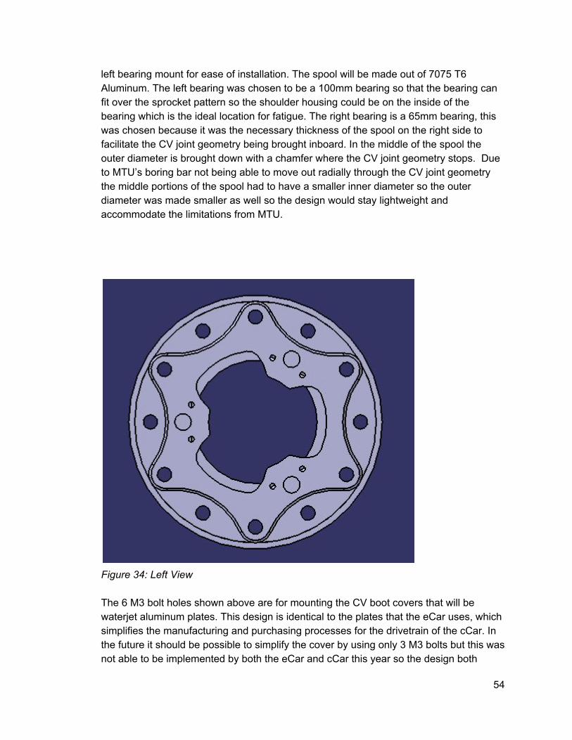
left bearing mount for ease of installation. The spool will be made out of 7075 T6 Aluminum. The left bearing was chosen to be a 100mm bearing so that the bearing can fit over the sprocket pattern so the shoulder housing could be on the inside of the bearing which is the ideal location for fatigue. The right bearing is a 65mm bearing, this was chosen because it was the necessary thickness of the spool on the right side to facilitate the CV joint geometry being brought inboard. In the middle of the spool the outer diameter is brought down with a chamfer where the CV joint geometry stops. Due to MTU’s boring bar not being able to move out radially through the CV joint geometry the middle portions of the spool had to have a smaller inner diameter so the outer diameter was made smaller as well so the design would stay lightweight and accommodate the limitations from MTU.
Figure 34: Left View The 6 M3 bolt holes shown above are for mounting the CV boot covers that will be waterjet aluminum plates. This design is identical to the plates that the eCar uses, which simplifies the manufacturing and purchasing processes for the drivetrain of the cCar. In the future it should be possible to simplify the cover by using only 3 M3 bolts but this was not able to be implemented by both the eCar and cCar this year so the design both
54

teams could use was chosen with a 3 hole design being considered for future enhancement of the 2017 car. The holes between the sets of m3 bolts are relief holes to save weight in the sprocket geometry.
Figure 35: CV Boot Cover
55

Figure 36: Right View
Figure 37: Side View
56

The chamfer sizes were increased over the course of design iteration when doing FEA analysis to compensate for minor stress concentrations at the two points where outer diameters change, without these large chamfers fatigue in those areas would have been a concern over the course of the season. Also, the chamfer locations and location of diameter change were chosen to make sure the spool was sufficiently thick over the entire length of the design.
Figure 38: Section Cut of Final Spool Design
Figure 39: Spool Inserts The inserts for the spool this year were changed to utilize the design that the eCar and spindles use for their CV joint housing. This insert is made out of steel and was chosen
57

for the spool because it is a simpler solution as far as manufacturing and built time, plus it is already used and proven to work in the eCar and outboard of the combustion car so getting a four more of them made would be a simple change to the purchase request that was already going to be made for these inserts.
Figure 40: Plug Housing Figure 41: Plug This is the design for the housing that will mount inside the spool and house the plug. This plug acts as a resting point for the plug at the end of the halfshaft. The design was chosen because it is lightweight and easy to install since it rests inside the CV joint geometry. It is planned to be made out of 7075 T6 aluminum but might be made out of still if it needs higher material properties to resist bending. The calculations for the halfshaft at this point are incomplete but will be finished by the end of finals week and once they are complete a material and shape can be chosen for this housing with load cases in mind. Advantages: 389 grams in weight savings Easier to install/maintain Bearing locations help reduce forces put on the bearings Part count is reduced with the monobody system
58

Disadvantages: Higher Moment of Inertia than 2015 design Monobody design limited diameter choices Requires a boring bar operation that is limited for MTU which constrained the design (A two piece spool might actually be able to save more weight than the monobody design with MTU’s boring bar limitations that are now known) Replacement of steel inserts or plug housing could be challenging due to the housing being pinned behind the inserts
Final Spool Mount Design
Design Constraint Adjustments: When more research was put into the idler chain tensioner and similar applications were found, there were mixed results. There were teams that had success using these chain tensioners and other teams found that their driver was experiencing a rough ride from engine braking compressing the spring loaded version of these chain tensioners. Furthermore, concerns with decreased efficiency in the drive chain and a sprocket being too heavy, a plastic roller chain tensioner that is not spring loaded became the viable design. This design was not selected as the only chain tensioner in the design, however, because research did not show an easy way to simulate and test the system for its viability. That is why the design presented below will be using an eccentric chain tensioner incorporated into the drivetrain mount and a stationary chain tensioner that will be designed during winter work week and will be used on the 2016 car to test its viability as the only chain tensioner for the 2017 car. Final Design:
59

Figure 42 Table 18
Final Drivetrain Mount
Max Length (mm) 404.4
Max Height (mm) 229.2
Max Width (mm) 15
Material 7075 T6
Aluminum
Weight (kg) 1.418
2015 Weight (kg) 1.34
Weight Saved (kg) 0.074
This design will utilize similar titanium bolts for the lower engine mounting and a thru bolt
60
for the top mounts since a large amount of distance has to be covered to secure both mounting plates to the top mounts of the engine. This mount utilizes eccentric plates to adjust the tension in the chain. Two M8 bolts will be used on the top and bottom of each mounting plate to create clamping force to prevent rotation of the eccentric plates. The force necessary was calculated using a code that takes into account the forces normal to the left and right bearings and the friction properties of 7075 T6 aluminum. The top bolt will need to be loosened to adjust chain tension. An adjustment apparatus has not been designed yet, but will most likely consist of a bar that can be threaded through relief holes in the eccentric plates to rotate the plates. Also, the final product will have etches in the top to help users dial in the ideal chain tension. These etches could be filed in post manufacturing once the design is installed and tested to see where the best chain tensioning locations are along the circumference of the mount. Shoulders exist on the outside of the mounts and the eccentric plates to secure the bearings and the eccentric plates. The shoulders on the mount also provides another frictional surface to keep the eccentric plates in position during operation of the car. Spacers will be used on the top and bottom of the right mount so that the mounts themselves do not need to have curved geometry to interface with the engine mounts. The designs of these spacers will be subject to change during winter work week to create a lightweight solution. The spacers will be made out of aluminum. Advantages: Simple to adjust Reduced part count from last years design Allows for exact adjustment Higher efficiency of rotation translation through the halfshafts (because of CV joint planes being brought inboard) Disadvantages: The need for spacers add extra weight to the system Tightening the clamping bolts will require a torque wrench to dial in the recommended value for the bolts As the mount and eccentric plate fatigue the adjustment could become more difficult over the course of the season Mount and eccentric plates must be made at a very low tolerance to make sure they interact correctly Added complexity to system will make it harder to find sponsors to machine it Weight is added compared to last year’s design
61

4.2 Technical Specification Create, and refer to, detailed engineering drawings, process diagrams, simulation results, facility layouts, or other appropriate tools to completely specify all aspects of the future state. Equations and sample calculations included and explained.
Spool Analysis When designing the spool one of the major challenges was adapting wall thickness for the varied diameters of the spool. Jeff Sprenger was able to help me by amending his code used for fatigue calculations for the spool last year to include the new bearing plane locations and the new CV joint geometry locations. This code was the key to dialing in the wall thickness so that the fatigue safety factor was somewhere between 1.2 and 1.5. That range of values was chosen since the spool is under high fatigue stress so failure due to fatigue is a major threat to the system. Final Spool Stress Calculations (found in appendix A section A.3) [5] Output: The Corrected Fatigue Strength is 84.710 (MPa) Static safety Factor w/ Stress Concentration is 4.69 2016 Fatigue Safety Factor Equation w/ Stress Concentration is 1.21 Goodman Safety Factor w/ Stress Concentration is 1.34 Gerber Safety Factor w/ Stress Concentration is 1.38 ASMEElliptic Safety Factor w/ Stress Concentration is 1.38 The results show that the final design meets the fatigue safety factor requirements. It also outputs a corrected fatigue strength that was then used during FEA analysis to find the portions of the spool that would start to fatigue first (FEA can be found in appendix B section B.1). For both scenarios the loading is being created on the sprocket. The Chain Back Tension Calculator code (appendix A section A.4) was used to find the forces in the teeth of the sprocket starting with the first tooth that makes contact at the top of the sprocket [5]. For the purpose of this analysis only the force in the first 10 teeth were used because the forces in the rest of the teeth are small enough to be considered insignificant. In the document you will see a list of the basic constraints that were used to set up the analysis. The slider constraints on the CV joint geometries are of particular interest in this analysis. This is because the constraints make it so the CV joint geometry takes up almost all of the torque in the system, which explains the large regions of blue seen in the analysis.
62

Figure 43 When adjusting the scale to have the corrected fatigue strength of 84.7 MPa (calculated in the spool fatigue code above) the image still does not show much load propagation down the spool.
63

Figure 44 To better understand the loading case a worst case situation was analyze. The worst case was taking a turn where the left wheel is off the ground and all torque is transmitted down the right side of the spool. This was done by removing the slider constraint on the left CV joint geometry. That scenario showed that stress concentrations existed along the two chamfers in the middle of the spool. This analysis helped us to improve the design by making the chamfers bigger so that the loading in those areas was well below the corrected fatigue strength to meet the safety factor requirements.
Bearing Selection When selecting bearings the size was one consideration but the other consideration was the dynamic load rating required by our bearings. A drivetrain rpm calculation code(appendix A, section A.5) was used to find out how many cycles the bearings had to
64

go through in a season and use the forces put onto the bearings (found using the spool force calculations found in appendix A section A.1) to find out the basic dynamic load rating required for each bearing. Output: Max Drivetrain RPM = 1747.04 Revolutions of Drivetrain for Season = 10254346.80 Dynamic Load Rating Required (Left Bearing) = 21.73 Dynamic Load Rating Required (Right Bearing) = 6.52
Drivetrain Mount Analysis
The first step to the analysis of the drivetrain mount was figuring out how much clamping force is necessary to keep the eccentric plate from spinning during operation.
Figure 45 This diagram shows the loading cases and the basic concepts used in the matlab code linked below to find the clamping force required out of each bolt in the mount design [5]. There are two values that needed to be found to do this analysis, the force normal to the left bearing and the coefficient of friction of 7075 T6 aluminum on itself.
65

The force normal to the left bearing was chosen because it is the max force in the system, so if the mounts are designed to handle the left load there is no doubt the right mount can handle the load being put on it. Force in Left Bearing 8775.38 (N) Force in Right Bearing 1633.67 (N) The coefficient of friction was chosen using a research paper on aerospace alloys [8]. On page 18 there is a graph showing the coefficient of friction of 7075 T6 on itself. It should be noted that this graph is of aluminum that was unmachined and unexposed to air so this is the worst case scenario graph of the coefficient. In this graph the line approaches .12 for increased loading so that value was chosen. In reality the actual coefficient between the aluminum will be higher but designing for the worst case scenario will guarantee a successful design. Using the above values and a safety factor coefficient to amplify the forces in the system, the eccentric plate bolt calculations (section A.5 of appendix) gives a recommended torque for each bolt on the drivetrain mounts [5]. Output: clamping force required per bolt (left mount) = 16052.52 clamping force required per bolt (right mount) = 2988.42 torque required per bolt (left mount) = 48157.57 (Nmm) torque required per bolt (right mount) = 8965.26 (Nmm) Using this data M8 12/9 bolts were chosen as clamping bolts since their recommended torque is around 50 Nm. FEA of Drivetrain Mount The first step in the FEA process was developing the constraints that would properly represent the loading case of the system. Outlined below is a step by step explanation of my constraining process. The full documentation form can be found in section B.2 of the appendix. The left mount was analyzed first as it would be seeing the highest stress of the system. The right side has an FEA shown at the end after the designs are finalized.
66

Figure 46 Constrain clamp to mount with 1mm offset constrain eccentric plate inside of mount
67

Figure 47 General analysis connection
Figure 48
68

Bolt Tightening Connection Property The bolt tightening connection ended up not functioning properly with the mesh analysis so the 1 mm offset was removed and a distributed force was applied to the bolt holes.
Figure 49 Distributed force added instead with rigid connection of bolt pattern
69

Figure 50 Rigid virtual part and clamp
70

Figure 51 Resist translation in y on the mount shoulders
71

Figure 52 Contact connection property between eccentric plate and the two mount components (must have surface contact constraints between plate and mount peices
72

Figure 53 Bearing Load broken into components After this the FEA was run and the initial result for the system was created.
73

Figure 54 The second iteration included pockets and a narrowing of the clamp to reduce weight.
74

Figure 55 Moving through the iterations a couple different pocket designs were tried that incorporated additional supports going across the mount.
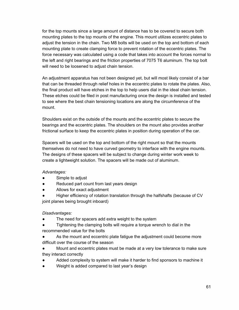
75
Figure 56 It was decided that the extra support and the bottom would not be necessary as the moment arm there is considerably shorter than on the top of the mounts. Final Design FEA:
76

Left Side:
Figure 57 Right Side:
77

Figure 58
4.3 Manufacturing Plan Fabrication plans and vendors indicated as appropriate. A detailed Manufacturing plan and schedule.
78
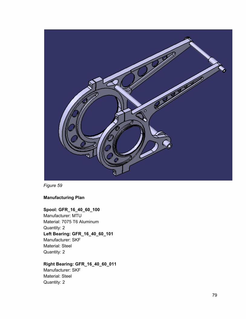
Figure 59 Manufacturing Plan Spool: GFR_16_40_60_100 Manufacturer: MTU Material: 7075 T6 Aluminum Quantity: 2 Left Bearing: GFR_16_40_60_101 Manufacturer: SKF Material: Steel Quantity: 2 Right Bearing: GFR_16_40_60_011 Manufacturer: SKF Material: Steel Quantity: 2
79

Halfshafts: GFR_16_40_40_001 Manufacturer: TBD (Pankle, RCV, Taylor Race) Material: 4130 Steel Quantity: 4 Tripod: GFR_16_40_40_003 Manufacturer: TBD (Pankle, RCV, Taylor Race) Material: Steel Quantity: 8 Drivetrain Inserts: GFR_16_40_60_102 Manufacturer: Biesinger GmbH (Could be subject to change depending on final sponsorship agreement) Material: Steel Quantity: 4 Sprocket: GFR_16_40_32_001 Manufacturer: Superior Sprockets Material: 7075 T6 Aluminum Quantity: 1x42 Tooth (Subject to change depending on team preference) Chain Guard: GFR_16_40_30_001 Manufacturer: OSU Material: 4340 Steel Quantity: 1 Drivechain: GB520 MXU Manufacturer: RK Racing Chain Material: Steel Quantity: 2 CV Boot Plate: GFR_16_40_43_001 Manufacturer: TBD (Waterjet sponsor) Material: 7075 T6 Aluminum Quantity: 4 Left Drivetrain Mount: GFR_16_40_70_000 Manufacturer: TBD (3axis milling sponsor needs to be found) Material: 7075 T6 Aluminum Quantity: 2 Right Drivetrain Mount: GFR_16_40_70_001
80

Manufacturer: TBD (3axis milling sponsor needs to be found) Material: 7075 T6 Aluminum Quantity: 2 Left Drivetrain Mount Clamp: GFR_16_40_70_003 Manufacturer: TBD (3axis milling sponsor needs to be found) Material: 7075 T6 Aluminum Quantity: 2 Right Drivetrain Mount Clamp: GFR_16_40_70_004 Manufacturer: TBD (3axis milling sponsor needs to be found) Material: 7075 T6 Aluminum Quantity: 2 Left Eccentric Plate: GFR_16_40_70_005 Manufacturer: TBD (3axis milling sponsor needs to be found) Material: 7075 T6 Aluminum Quantity: 2 Right Eccentric Plate: GFR_16_40_70_006 Manufacturer: TBD (3axis milling sponsor needs to be found) Material: 7075 T6 Aluminum Quantity: 2 Mount Support Crossmember: GFR_16_40_70_002 Manufacturer: GK Material: Aluminum Quantity: 2 Right Upper Engine Mount Spacer: GFR_16_40_70_020 Manufacturer: OSU Material: Aluminum Quantity: 2 Right Lower Engine Mount Spacer: GFR_16_40_70_030 Manufacturer: OSU Material: Aluminum Quantity: 2 Halfshaft Plungers: Manufacturer: OSU Material: Plastic Quantity: 8
81
Spool Plug: Manufacturer: OSU Material: Plastic Quantity: 4 Inboard CV Boot Rings: Manufacturer: TBD Material: Rubber Quantity: 8 Outboard CV Boot Rings: Manufacturer: TBD Material: Rubber Quantity: 8
5. Implementation The manufacturing and assembly of this project will be outlined in section C of the appendix. The appendix will include major adjustments to the design due to manufacturing limitations. The drivetrain mounts were made using Fadal CNC machines in the Oregon State University machine shop, the edgecam work and the machining process are further explained in the appendix as well. This section will focus on the strengths and weaknesses of implementing a locked drivetrain system. This will include an analysis of how the 2016 car can be better tuned to accommodate for those strengths and weaknesses. When analyzing ways to tune the car, the vehicle dynamics and suspension adjustability will be heavily focused on. The necessity for this portion of the project arose after competing in Michigan. Due to inclement weather on the day of endurance the car did not perform up to standard and drivers were struggling with a large amount of understeer. These issues lead to the idea that further development needs to be done on wet testing of the car and suspension tuning to accommodate for understeer in the system. Hopefully the ideas discussed below can be implemented and tested before going to competition in Germany and Austria, but they can also serve as future enhancement for the development of the 2017 car. 5.1 Effect on Handling In FSAE competitions three out of the four dynamic events require the car to take turns in narrow courses. This means that the car's ability to turn and the driver’s ability to
82

handle the car effectively are two of the most point sensitive aspects that drive the design of the car. This is why the characteristics of handling with a spool drivetrain will be considered at corner entry and corner exit. With a fully locked drivetrain the wheels are forced to try and go the same speed, this can become an issue in cornering because the inside and outside wheel need to travel different sized arcs during the turn. Therefore, on corner entry the inside wheel is forced to have a higher slip rate, which with enough traction on the ground can create a yaw resisting moment that will manifest as understeer for the driver [9]. To reduce the magnitude of that moment the suspension can be tuned to have more inside wheel lift. There are a few ways to achieve more inside rear wheel lift that are easily achieved with the 2016 car’s suspension. They include the installation of anti roll bars, reducing spring rates, and increasing caster. These adjustments will promote wheel lift, meaning the outside tire will have more traction and the car will have less understeer [10]. Anti roll bars are a component that will be tested after Michigan as a way to help handling of the car, further details of this testing can be found in the section below. By adjusting the bias between the front and rear anti roll bar stiffness inside wheel lift can be dialed to the point that understeer does not affect the driver, while oversteer does not become a problem on corner exit. Spring rates affect the car’s load transfer during cornering, by softening the front springs or stiffening the rear spring understeer can be reduced but oversteer problems could arise with too stiff of rear springs. Furthermore, adjusting springs will require an adjustment of ride height, which will need to be considered for the different rules for ride height at FSG. Caster can affect the ability of the front suspension to self center, by applying negative caster you can reduce promote inside wheel lift but also risk too much oversteer [11]. When considering the options listed above the simplest option to try first is the installation of the anti roll bars. By installing those and dialing in the preferred stiffness the team can establish a baseline for the suspension and adjust from there if understeer and oversteer are still an issue navigating slaloms and other tight corners. When considering all of these adjustments it is also important to understand the capabilities and the feedback of the drivers. The car can only drive as fast as it’s drivers, so making sure they are comfortable with the suspension tuning is as important as improving the setup for a locked drivetrain system.
6. Testing
6.1 Tests Complete to Date The only tests that have been completed as of now were the tests done on the edgecam code for the drivetrain mounts. Before manufacturing of the mounting subsystem began plastic was used as a test material to run the cnc code that was written using edgecam. This gave an opportunity to debug the code and better understand how the stock would need to be fixtured to manufacture the mounts.
83

Figure 60: First operation tested on the CNC After running these tests we were able to learn more about the machining operation settings in edgecam and take advantage of options such as path optimization and waveform cutting to increase depth of cut while reducing wear on the tool being used. This helped to save anywhere between 515 minutes depending on the operation being done and provided accurately dimensioned parts due to minimal tool chatter.
84

Figure 61: Next phase in machining operation Testing showed that using a mill to pocket out completely circular holes resulted in a off tolerance part. An adjustment was made and drills were added to make the holes the correct size for their bolts. This is significant because the engine bolts need to have a tight fit so they are not deflecting within the mount and wearing away at the aluminum.
85

Figure 62: Fixturing for profile operations
86

Figure 63: Fixturing for final profile operation Testing proved to be invaluable for gaining insight on how to fixture the part and how to order the machining operations. One way future manufacturers of the drivetrain can save time is designing a part that can be machined with less re fixturing over the course of the machining process. That by far took the longest time due to the complicated nature of the drivetrain mount geometry. Furthermore, going back through the edgecam code and adding larger clearance planes can save time so that the machine will pass over your fixtures as it moves around the part. This was an oversight this year that caused the machine to need to be stopped and a fixture to be moved, which can add up to a lot of time wasted when making 8 components that each require multiple machining operations.
Figure 64: Finished testing product The testing of the edgecam code took a significant portion of time but was necessary to learn more about machining and provide a safe opportunity for debugging a code since there was a lack of in depth knowledge among current teammates about edgecam and
87

using the CNC machines. It turned out to be more beneficial than expected because of all the little improvements that were adopted along the way that saved countless hours when machining the real parts. Furthermore, now that this testing has been done there is a baseline that future members can use and write code that does not need to be tested as rigorously and parts can be made faster and with more precision as the years go on and knowledge is shared among teammates. 6.1.3 Anti Roll Bar Testing Over the course of the week following the competition in Michigan the anti roll bars were installed on the car. Custom mounts were made for the bar using the Fadal CNC, Igus plastic was also machined out along with bushings to install the bars to the chassis and the suspension. The first bar installed was a half inch bar with a 0.35 inner diameter. This was the smallest bar that was bent. It was decided to start with the softest bar and slowly increase the stiffness, this is because wheel lift can create instability in the car and safety of the drivers and people at the test site is crucial. Giving the drivers time to get use to the different anti roll bar settings will result in a safer environment that will not only improve the car but improve the driver’s comfort level with the car. That weekend the car was taken testing to see if anti roll bars made a difference in the lap times on the asymmetric oval course. The idea for the test is that the anti roll bars would be disengaged from the suspension and hang from the chassis while both drivers ran laps in both directions on the track. This way the car would be at a static weight for the lap time comparisons. Then, the anti roll bars would be reattached and the car would be run again and the lap time would be compared. The roll bar stiffness would then be adjusted by moving the location of the clamp that connect them to the suspension to make the rear of the car stiffer. A test like this has a lot of factors to be considered like the driver fatigue, tire wear and the time of day the tests are conducted. To manage the temperature difference over the day the tests need to be done back to back in a relatively short amount of time. That being said, if the lap time changes significantly compared to the 1112 second lap times there are conclusions that could be made despite the factors that can skew the data. Results
88

Figure 65: Average and fastest lap times.
Figure 66: Average and fastest lap times.
89

Figure 67: Lap times for different ARB settings.
Figure 68: Lap times for different ARB settings. The data above shows a steady decrease in lap time from increasing the stiffness of the rear of the car. Brian Boly’s data is not as conclusive as Ryan’s because he felt that there were other factors in his driving that were improved over the course of the day. This is shown by the line graphs that not only show a consistency comparison between the two drivers but that his driving was not consistent enough to be able to say that the ARBs made a considerable different. For Ryan Thoma’s data there is a steady and
90

significant decrease in lap time as the rear of the car gets stiffer. He also said that the car itself felt fast and in control with the different settings. This is an important factor because understeer can only be corrected as far as the driver’s are comfortable driving the car. Overcorrection of understeer is possible and the car could become too difficult to drive so the driver feedback is important to consider. This data helps to show that anti roll bars will help the car drive faster and should be further tested. Going forward more anti roll bars should be tested and the front anti roll bar should be installed on the car. Furthermore, once ARB testing is done spring stiffness and caster should be tested to further understand the adjustability of our suspension and where we can make the car faster depending on driving conditions.
6.2 Tests to Complete The tests that are planned of the drivetrain include a study of the strain on the drivetrain mounts, and energy loss through the drivetrain. Putting strain gauges on the upper members of the drivetrain mounts would help to show the stresses in the area that seem most likely to break. The data taken from these gauges will need to be calibrated by using the spare mounts and an instron fixture. The stress values can then be compared to the FEA done on the mounts to better understand how accurate the FEA was and what loads the mount is realistically seeing. This could help improve the design of the drivetrain mount for the 2017 car. The final test that is being planned is the use of wireless strain gauges to understand the energy loss in the system. Using information known about the engine and the drivetrain system we could better understand how much energy is lost in the system. This information will give a baseline for next year's design so that a design goal can be reducing energy loss in the system. 6.2.1 Strain Gauge Test Procedure Configuration Options Currently the wiring system for the car has two vacant spots that strain gauges can be hooked up to so that data can be pulled easily from the system. When considering how to collect the data a quarter and half bridge arrangement were considered.
91

Figure 69: Quarter bridge configuration [12]. The standard quarter bridge could measure strain in one direction. This would work for the drivetrain mounts since the transverse load on the system is not considered in the FEA. However, this configuration is susceptible to temperature based variance.
Figure 70: Quarter bridge configuration with a dummy gauge not bonded to the surface [12]. This configuration utilizes a dummy gauge that is positioned perpendicular to the forces we are interested in collecting. This establishes a voltage ratio that can be used to account for the effects of temperature on the gauges [12].
92

Figure 71: Two different half bridge configurations, top is to measure axial and bending strain and bottom is bending strain only [12]. This configuration is twice as sensitive as the corner bridge [12]. The top configuration would be preferable for this application because axial and bending stress are important to consider. However, this setup is more complex and would only be used if it was decided that transverse stress is of interest to study. Application Procedure When applying the strain gauges the drivetrain should be removed from the car to make sure it is done in a clean environment where the gauges will be applied accurately. The first step is to degrease the strain gauge using a solvent such as isopropyl alcohol. After this point it is important that the user avoids getting any dirt or grease on the gauge or the surface they are being applied so gloves are recommended. Next, the surface they are applied to must be abraded. This can be done with a conditioner and a 320 grit silicon carbide paper (recommended for aluminum). Once the surface is shiny make sure to wipe the surface dry with a sponge. Then the layout lines should be drawn with a lead pencil so that the strain gauge can be put in the desired location. The conditioner is then reapplied and the surface scrubbed with a cotton tip applicator until the tip does not become discolored by swabbing the surface. After that, the surface must be neutralized with a solution using cotton tipped applicators [13]. The surface is now ready to have the strain gauge applied. The strain gauge must be removed from the protective film and placed on a clean surface like a sheet of glass with the bonding surface down. Then use a cellophane tape to stick onto the strain gauge and remove it from the glass surface. The tape and gauge can then be placed on the mount in the correct location and the tape can be peeled back until the bonding surface is free. An illustration is shown below [13].
93

Figure 72Example of how the strain gauge and tape should look before applying bond material [13]. At this point the instructions depend on the bonding material that is being used. In this case I will use whatever material we already have in the shop which is Analysing the Data To get usable data from the strain gauges a series of equations must be used. The first equation is to transition the data from voltage to strain, this equation depends on what type of setup is used. Below is a set of equations for the quarter and half bridge which were discussed earlier as potential setups for the experiment.
94

Figure 73: Circuit diagram for a quarter and half bridge with strain equations [14]. Once the data is converted to strain the strain can be used to find the stress at the gauge. To find this stress a calibration needs to be done using the school’s instron machine to figure out the approximate load occurring at the gauge location. This could be done by designing a fixture for each mount and applying a load to them in the machine. The fixture should be a board with fixture holes for the top and bottom engine mounts and for the crossmember mounting hole. The board should be sloped on the top side so that there is an exposed surface of the mount to apply the load at. Using the calibration results the strain values should be able to be paired with an accompanying load that can generate stress values using basic material and geometry properties. Fundamental equations to do this can be found in Shigley’s Book of Mechanical Design [5]. 6.2.2 Rotational Strain Gauge The wireless strange gauge is built to be housed on a driveshaft and used to measure torque. Oregon State’s Baja team was able to acquire one of these sensors and had a custom housing 3D printed for it. Since the driveshaft for the baja car was .2 inches larger than ours a custom sleeve was going to be made so the gauge could be mounted onto the formula car as well. The idea here is that the losses through the spool would be able to be calculated since the torque the engine is outputting is known so the difference between those values would give the losses due to the drivetrain. This is valuable information because losses through the drivetrain are difficult to find. Even just for chains
95

and CV joints there are master's level papers trying to predict the losses in the system that still do not give enough information to be able to predict the losses in a practical application setting. When deciding where on the halfshafts to mount the strain gauge it was discovered that packaging would be a serious issue. There is limited room between the halfshaft and other components of the car meaning that the housing used for the baja car would not work for our car. This is the driving reason why that test was not completed before the completion of this paper. It was not possible to balance getting the car ready for Michigan and designing a new housing to be manufactured for the gauge. The test, however, could be accomplished this summer before the start of the design phase for the 2017 car so the new designer will have more benchmark values to try to improve on.
7. Conclusion
7.1 Sub Section 1: Improvements to the Design The first set of improvements will involve the spool design. First and foremost, a locked versus unlocked drexler test needs to be run on the 2015 car. Preferably this study would also be split up into a dry run and a wet run to fully understand the speed differences between the two configurations. Information from this test will be valuable for 2017 design presentations and will guarantee the best type of drivetrain is chosen for the 2017 car. A better study of bearing choice is also recommended for next year. The bigger left bearing is used to accommodate the sprocket being bolted through the spool. The right bearing was changed to the same bearing as the spindle, but we have a source for cheap bearing so there is an opportunity there for a better right bearing to be chosen to further improve the spool’s design. Also, next year there should be a search for a spool manufacturing sponsor that has more boring bar capabilities. This would make it possible for the spool to be made lighter. Another option for making the spool lighter would be a new two piece design so that a boring bar is not needed but this would increase complexity so next year’s designer will have to determine what they want to accomplish and how to balance improvement with increased complexity. The drivetrain mounts have a couple improvements that could also be applied next year if the design idea is kept the same. First off, the mounting holes for the left mount need to be moved so that custom shims do not need to be made for the bolts. By moving the holes up it also removes the need for a helicoil and for safety wire, meaning chain tension can be adjusted faster. Second, the eccentric plates were made with more adjustability than what is needed for tensioning the chain. Next year smaller plates could be used which would severely reduce the mass of the system. Also, after completing the tests on the strain in the mounting system there will be more data to use to decrease the weight of the drivetrain mounting system for the 2017 car. Furthermore, any data found
96

about strain in the system should be used to update the FEA done on the drivetrain mount to increase it’s accuracy, thus improving the value of that tool for years to come. Finally, the machining time of the system could be reduced by someone who has more manufacturing, or edgecam experience. I would recommend consulting someone in the manufacturing department of a company we are sponsored with.
7.2 Sub Section 2: Improvements to Project Management One of the major follies of this project was insufficient urgency in relation to sponsor searching. If sponsors were found earlier in the design process the manufacturing stage of the project would have taken considerably less time. Furthermore, by finding new sponsors, with increased machining capabilities, there will be more room for the designer to improve the drivetrain system. It should be stressed that the success of this project was heavily reliant on collaboration between me and my teammates. Working closely with Jeff Sprenger, Carson Strand, and Patrick Hinkle helped me to learn about last year’s drivetrain and about designing/manufacturing this year's drivetrain. There expertise in vehicle dynamics and machining helped me learn things that would have taken a significant amount of time to learn on my own. Furthermore, members of Baja were an essential edgecam resource because they were not only able to help me learn the program, but reduce the machining time by utilizing certain features of edgecam. With this report as a tool, the 2017 drivetrain design should be able to be lighter, and manufactured easier than this year, if all of the resources available are used properly.
8. Works Cited 1. 2015 Formula SAE Rules, SAE International, Rev. Sep. 2014. 2. Global Formula Racing Private Home Wiki, “Equating Design Parameters to Points,” https://sites.google.com/a/baracingteam.de/globalformularacinggeneral/wike/theoryandanalysis/1_generaldesigntheory/equatingdesignparameters, accessed Sep. 2015. 3. Sprenger, J., “2015 Drivetrain Report,” Senior Project, Mechanical Engineering Department, Oregon State University, Corvallis, 2015. 4. Bolt Science, “Vibrational Loosening of Bolts and Threaded Fasteners,” http://www.boltscience.com/pages/vibloose.htm, accessed May, 2016. 5. Budynas, R., Nisbett, J., “Shigley’s Mechanical Engineering Design, Tenth Edition,” (McGrawHill Education, 2015), 85124, 273338, ISBN 9780043398204. 6. Fuglede, N., Thomsen, J., “Kinematic and dynamic modeling and approximate analysis of a roller chain drive,” Journal of Sound and Vibration, 366: 447470, 2016, doi:10.1016/j.jsv.2015.12.028 7. Biermann, J., "Measurement System for CV Joint Efficiency," SAE Technical Paper 1999010936, 1999, doi:10.4271/1999010936.
97

8. Mohan, K., “Frictional Analysis of Aerospace Alloys and Composite Materials,” The School of Mechanical and Manufacturing Engineering, University of New South Wales, Sydney, 2011. 9. Alfredson, J., “Locking Differential,” US Patent 7,654,934 B2, February 2, 2010. 10. Taylor, C., “Differentials and Chassis Setup,” Taylor Race Engineering, http://www.taylorrace.com/pdf/understanding_differentials.pdf, accessed May, 2016. 11. RapidRacer, “Suspension Tuning,” http://www.rapidracer.com/suspensiontuning.php, accessed May, 2016. 12. National Instruments, “Measuring Strain with Strain Gages,” http://www.ni.com/whitepaper/3642/en/, accessed May, 2016. 13. Vishay Measurements Group, “Introduction to Strain Gage Technology,” http://www.egr.unlv.edu/~bj/MEG_302L_web/Student_strain_gage_Manual001.PDF, accessed May, 2016. 14. Agilent Technologies, “Practical Strain Gage Measurements,” https://docs.google.com/a/oregonstate.edu/file/d/0B9OPr64SL1YFZHRhXzVKOHJDbzA/edit, accessed Oct. 2015.
98

Appendix A: Matlab Code
Section A.1:
Spool Shear and Moment Calculations %%SPOOL Calculations for Shear and Moment Diagrams %Using: torque from 2014 report. Using: sprocket radius and coordinates of %Sprocket plane, Left Bearing Plane, Right Bearing Plane (lengths can be %determined from basic coordinate math in Y) %%%%%%%%%%%%%%%%%%%%%%%%%%%%%%%%%%%%%%%%%%%%%%%%%%%%%%%%%%%%%%%%%%%%%%%%%%% clear;clc Torque=760, %Output Torque (N*m) SprocketR=106.417/1000 %drive sprocket diameter m S=Torque/SprocketR; %Chain Tension (N) fprintf('Chain Tension is %6.2f (N)\n',S) fprintf('at angle of 40.2 deg from X axis \n\n\n') L1=27.45; %From Sprocket to Center L Bearing (mm) L2=120; %From Center L Bearing to Center R Bearing (mm) L3=L1+L2; %From Sprocket to center R Bearing (mm) %%%%%%%%%%%%%%%%%SudoCode for Sum of Forces and Moments%%%%%%%%%%%%%%%%%%% %From Sum of Forces and Moments % Sum F= S FL + FR = % Sum M (about S)= FL*L1 + FR*L3 = 0 %%%%%%%%%%Solved Equations FL=S*(L3/L2); % Force in Left Bearing (N) FR=FLS; % Force in Right Bearing (N) %%%%%%%%Output fprintf('Force in Left Bearing %6.2f (N) \n',FL) fprintf('Force in Right Bearing %6.2f (N) \n',FR) %%%%%%%%%%%%%%%%%%%%%%%%%%%%%%%%%%%%%%%%%%%%%%%%%%%%%%%%%%%%%%%%%%%%%%%%%%% %LBI=Left Bearing Inboard LBO=Left Bearing Outboard %RBI=Right Bearing Inboard RBO=Right Bearing Outboard %Sp=Sprocket %%%%%%%%%%%%%%%%%%%%%%% Equations for F V M diagrams%%%%%%%%%%%%%%%%%%%%%%% l1=20.95; %Sp to LBO (mm) l2=13; %LBO to LBI (mm) l3=108.5; %LBI to RBI (mm) l4=10; %RBI to RBO (mm)
99

DL=FL/l2 %L bearing distibuted load (N/mm) DR=FR/l4 %R bearing distibuted load (N/mm) fprintf('\n\n') %V V1=S %Shear (from Sp to LBO) (N) V2=V1(DL*l2) %Shear (at LBI) (N) V3=V2+(DR*l4) %Shear (at fprintf('\n\n') %Zero Points Z1=V1/DL %Loctaion of zero V and Max M (measured from LBO) (mm) Z2=l2Z1 %Loctaion of zero V and Max M (measured from Z1 to LBO) %M M1=V1*l1 %Moment at LBO (N*mm) M2=M1+(DL/2)*(Z1^2) %Max Moment at Z1 (N*mm) M3=M2(DL/2)*(Z2^2) %Moment at LBI (N*mm) M4=M3+V2*l3 %Moment at RBI (N*mm) M5=M4(DR/2)*(l4^2) %Moment at RBO (N*mm) x=23.841 %distance of interest measured from LBI Mx=M3((M3M4)/(l3))*x %%%%%%%%%%%%%%%%%%%%%%%%%%%%%%%%%%%%%%%%%%%%%%%%%%%%%%%%%%%%%%%%%%%%%%%%%%% Output: Torque = 760 SprocketR = 0.10642 Chain Tension is 7141.72 (N) at angle of 40.2 deg from X axis Force in Left Bearing 8775.38 (N) Force in Right Bearing 1633.67 (N) DL = 675.03 DR = 163.37 V1 = 7141.7 V2 =
100

1633.7 V3 = 0 Z1 = 10.58 Z2 = 2.4201 M1 = 1.4962e+05 M2 = 1.874e+05 M3 = 1.8542e+05 M4 = 8168.3 M5 = 7.0031e11 x = 23.841 Mx = 1.4647e+05
101

Section A.2: Drivetrain Force Calculations
% ======================================================================== % 2016 Left Diff Bracket Forces (Concept Juicy J) clear, clc, format compact, format shortg, %close all fprintf('=====================================================================\n') fprintf('Calculations for 2015 Left Diff Bracket Forces (Juicy Jay Concept)\n') fprintf('\n\n') % ========================================================================= % Calculating the tension in the chain % T_engine = 760; % [Nm] Max engine torque (w/o SF) from 2011 Drivetrain Final Report d_S = 106.233/1000; % drive sprocket diameter [m] F_T = T_engine/d_S; % max Chain tension [N] fprintf('Max Chain Tension was approximated to be %5.1f kN\n',F_T/1000) fprintf('(using calculations from the 2011 Drivetrain Final Report)\n\n') BT = 79.450; % [Nm] Max braking torque (w/o SF) used for 2011 Drivetrain Final Report % ========================================================================= % Calculations for 2D reactions in the diff brackets (in the direction of % chain tension). Xdirection is towards the front of the car, which is % taken to be the direction of chain tension (tension has positive xvalue % but negative zvalue). % % F_DL = force on bearing from Left Diff Mount % F_DR = force on bearing from Right Diff Mount % Ls_L = length between sprocket and left diff plate from CAD [m] % Ls_R = length between sprocket and right diff plate from CAD [m] Ls_L = 39.45/1000; % Length from sprocket to left diff plate [m] Ls_R = 149.35/1000; % Length from sprocket to right diff plate [m] L_lptrp = Ls_RLs_L; %Distance of left mount plate from right mount plate
102

% Sum of Moments about Right Diff Plate: % F_T*(Ls_R) + F_DL*(Ls_RLs_L) = 0 % solving this for the force, F_DL, gives us F_DL = F_T * Ls_R / L_lptrp; % Sum of Forces in the x direction: % F_T+F_DL+F_DR=0 % solving this for the force, F_DR, gives us F_DR = F_TF_DL; fprintf('The force exerted on the left Diff bracket bearing is %5.1f kN\n',F_DL/1000) fprintf('The force exerted on the right Diff bracket bearing is %5.1f kN\n',F_DR/1000) fprintf('From the chain, the left bracket sees %3.f%% more force than the right bracket.\n\n',abs(F_DL/F_DR*100)) % NOTE: The forces calculated above for L and R diff brackets are reactions % from the diff plates onto the bearings. For the bracket analysis, the % reactions from the bearings onto the diff plates must be used. Thus the % force below is reversed. F_DL = F_DL; % ========================================================================= % Finding forces in the members of the diff brackets/supports % % Step 1: Define coordinates and angles (2D only) from 2015 CAD model % LocD = [2.584 , 0.195]; % [m] location of diff axis LocU = [2.300248 , 0.308673]; % [m] location of upper mount on engine (below intake) LocL = [2.463489 , 0.143837]; % [m] location of lower motor mount (rear of engine) Th_Ch = 40.2; % [º] angle of chain with ground (and therefore diff bearing reactions)
103

% $$$$$$$$$$$$$$$$$$$$$$$$$$$$$$$$$$$$$$$$$$$$$$$$$$$$$$$$$$$$$$$$$$$$$$$$$ % $$$$$$$$$$$$$$$$$$$$$$$$$$$$$$$$$$$$$$$$$$$$$$$$$$$$$$$$$$$$$$$$$$$$$$$$$ % $$$$$$$$$$$$$$$$$$$$$$$$$$$$$$$$$$$$$$$$$$$$$$$$$$$$$$$$$$$$$$$$$$$$$$$$$ % $$$$$$$$$$$$$$$$$$$$$$$$$$$$$$$$$$$$$$$$$$$$$$$$$$$$$$$$$$$$$$$$$$$$$$$$$ % $$$$$$$$$$$$$$$$$$$$$$$$$$$$$$$$$$$$$$$$$$$$$$$$$$$$$$$$$$$$$$$$$$$$$$$$$ % $$$$$$$$$$$$$$$$$$$$$$$$$$$$$$$$$$$$$$$$$$$$$$$$$$$$$$$$$$$$$$$$$$$$$$$$$ % % Change These Below to Visualize Geometry % rTx = LocU(1)LocD(1); % [m] distance of top diff mount from diff axis (xdirection) rTz = LocU(2)LocD(1); % [m] distance of top diff mount from diff axis (zdirection) rT = sqrt(rTz^2+rTx^2); % [m] distance of top diff mount from diff axis (shortest distance) Th_T = atand(rTz/rTx) ; % [º] angle of top diff mount (from positive xdirection) rBx = LocL(1)LocD(1); % [m] distance of bottom diff mount from diff axis (xdirection) rBz = LocL(2)LocD(2); % [m] distance of bottom diff mount from diff axis (zdirection) rB = sqrt(rBz^2+rBx^2); % [m] distance of bottom diff mount from diff axis (shortest distance) Th_B = atand(rBz/rBx); % [º] angle of bottom diff mount (from positive xdirection) % $$$$$$$$$$$$$$$$$$$$$$$$$$$$$$$$$$$$$$$$$$$$$$$$$$$$$$$$$$$$$$$$$$$$$$$$$
104

% $$$$$$$$$$$$$$$$$$$$$$$$$$$$$$$$$$$$$$$$$$$$$$$$$$$$$$$$$$$$$$$$$$$$$$$$$ % $$$$$$$$$$$$$$$$$$$$$$$$$$$$$$$$$$$$$$$$$$$$$$$$$$$$$$$$$$$$$$$$$$$$$$$$$ % $$$$$$$$$$$$$$$$$$$$$$$$$$$$$$$$$$$$$$$$$$$$$$$$$$$$$$$$$$$$$$$$$$$$$$$$$ % $$$$$$$$$$$$$$$$$$$$$$$$$$$$$$$$$$$$$$$$$$$$$$$$$$$$$$$$$$$$$$$$$$$$$$$$$ % $$$$$$$$$$$$$$$$$$$$$$$$$$$$$$$$$$$$$$$$$$$$$$$$$$$$$$$$$$$$$$$$$$$$$$$$$ LocT = LocU; % [m] location of Top mounting point on diff bracket LocB = LocL; % [m] location of Bottom mounting point on diff bracket %Th_BL = atand( (LocL(2)LocB(2)) / (LocL(1)LocB(1))); % [º] angle of bottom turnbuckle with ground (Theta, B to L) % Step 2: Sum moments about non2 force reaction to find tension in % turnbuckle % % Sum moment about new upper bracket mount: % Force xcomponent * delta_z hgt + force zcomponent * delta_x hgt ... =0 F_DLcomp = [F_DL*cosd(Th_Ch), 0 , F_DL*sind(Th_Ch)]; % [N] components of chain force acting on diff r_DLcomp = [rTx, 0, rTx]; % [m] components of "r" vector from top diff pivot to diff center M=[r]x[F] syms F_BL F_BLcomp = [F_BL*cosd(Th_B), 0, F_BL*sind(Th_B)]; % [N] symbolic components of force acting on bottom diff mount r_BLcomp = [rTxrBx, 0, rTzrBz]; % [m] components of "r" vector from top diff pivot to bottom diff mount
105

Mtemp = cross(F_DLcomp,r_DLcomp) + cross(F_BLcomp,r_BLcomp); % M=[r]x[F] F_BL = double(solve(Mtemp(2),F_BL)); fprintf('The (bottom) Engine Mount exerts a %5.1f kN force on the diff bracket\n',F_BL/1000) fprintf('at an angle of %3.1f degrees (with the positive xaxis).\n',Th_B) fprintf('(For the force in the member: positive > tension, negative > compression\n\n') % Step 3: Find force acting on the Top Pivot of diff (F_TP) % % Sum forces acting on left diff bracket in x and z: F_TPx = (F_DL*cosd(Th_Ch) + F_BL*cosd(Th_B)); F_TPz = (F_DL*sind(Th_Ch) + F_BL*sind(Th_B)); Th_TP = atand(F_TPz/F_TPx); F_TP = sqrt(F_TPx^2 + F_TPz^2); % force acting on upper mount % Used to correct sign of force for upper bracket mount: if F_TPx <0 && F_TPz<0 F_TP = F_TP; elseif F_TPx <0 && F_TPz>0 F_TP = F_TP; end fprintf('The (top) Engine Mount exerts a %5.1f kN force on the diff bracket\n',F_TP/1000) fprintf('at an angle of %3.1f degrees (with the positive xaxis).\n\n',Th_TP) % Step 4: Find forces in TU and TL. These members go from the upper diff % mount to the engine. Tension = positive, compression = negative % % Assign angles theta_TU & theta_TL (the angle measured from the +x axis % of the member from the upper diffplate and theta_TU (the angle measured % from the +x axis of the member from the upper diffplate pivot to the % upper engine mount). %Th_TU = atand((LocU(2)LocT(2))/(LocU(1)LocT(1))); % [º] %Th_TL = atand((LocL(2)LocT(2))/(LocL(1)LocT(1))); % [º] % Sum forces at the top pivot and solve for the unkown tensions in members
106

% Eq1: Sum Fx 0 = F_TP*cosd(Th_TP) + F_TU*cosd(Th_TU) + F_TL*cosd(Th_TL) % Eq2: Sum Fy 0 = F_TP*sind(Th_TP) + F_TU+sind(Th_TU) + F_TL*sind(Th_TL) % We have two Eq's and two unknowns (F_TU and F_TL). Manipulate to solve: % Ask Gabe to comment how this works if needed syms F_TU F_TL Eq1 = F_TP*cosd(Th_TP) + F_TU*cosd(Th_T) + F_TL*cosd(Th_B); Eq2 = F_TP*sind(Th_TP) + F_TU*sind(Th_T) + F_TL*sind(Th_B); tempF_TL = solve(Eq1,F_TL); tempF_TU = double(solve(subs(Eq2,F_TL,tempF_TL),F_TU)); F_TL = double(subs(tempF_TL,F_TU,tempF_TU)); F_TU = tempF_TU; fprintf('Assuming pin joints for all of the engine supports, we have that following loaded members:\n') fprintf('\n') fprintf('Top Diff Mount > Upper Engine Mount:\n') fprintf('Force in member = %5.1f kN\n\n',F_TU/1000) fprintf('Top Diff Mount > Rear Engine Mount:\n') fprintf('Force in member = %5.1f kN\n\n',F_TL/1000) fprintf('Bottom Diff Mount > Rear Engine Mount:\n') fprintf('Force in member = %5.1f kN\n\n',F_BL/1000) fprintf('(For the force in the member: positive = tension, negative = compression\n\n') % ========================================================================= % Plot Results for 2016 Left Diff Bracket (Juicy Jay Concept) % clf figure(1) title('2016 Left Diff Mount and Forces (Juicy Jay Concept): r_T=0.060 m, \theta_T = 105^o, r_T=0.080 m, \theta_T = 90^o,') xlabel('Global xlocation in CATIA [m]') ylabel('Global zlocation in CATIA [m]') hold on plot([LocT(1),LocD(1),LocB(1)],[LocT(2),LocD(2),LocB(2)],'r')
107

% Lines connecting diff members are shown as dashed blue plot([LocU(1),LocT(1),LocL(1),LocB(1)],[LocU(2),LocT(2),LocL(2),LocB(2)],':b') % Lines connecting engine members to diff are shown as dotted black % Plot Chassis opening (for chain) can change height but thk is correct) ChassisOpening = [ 2.516 0.075 2.516 0.305 2.496 0.305 2.496 0.075 2.516 0.075]; plot(ChassisOpening(:,1),ChassisOpening(:,2),'k') text(2.49,0.07,'Chassis Location') legend('Diff member','Engine supports','Location','Best') axis([2.75 2.1 0 0.35]) % Color Scheme Explanation text(2.54,0.025,'*Forces acting on diff are black, acting on members are blue') AS = 40000; % Arrow Scale used below in quiver command rM = .020; % aesthetic radius of mount hole for plot rD = .065; % aesthetic radius of Diff Diameter for plot % Diff text and forces % text(LocD(1).12,LocD(2),'F_Chain Force Reaction at Bearing') rectangle('Position',[LocDrD/2 rD rD], 'Curvature',1, 'edgecolor','r') % Applied Chain Force arrow quiver(LocD(1), LocD(2), F_DL*cosd(Th_Ch)/AS, F_DL*sind(Th_Ch)/AS,'k') % Top Pivot text and forces % text(LocT(1)+.09,LocT(2).05,'F_Top Mount on Diff (black)') rectangle('Position',[LocTrM/2 rM rM], 'Curvature',1, 'edgecolor','r') % Top Pivot Force on Diff quiver(LocT(1), LocT(2), F_TP*cosd(Th_TP)/AS, F_TP*sind(Th_TP)/AS,'k') % Upper Engine Mount Force quiver(LocT(1), LocT(2), F_TP*cosd(Th_TP)/AS, F_TP*sind(Th_TP)/AS,'b') % Top Diff Pivot > Rear Engine Mount arrow quiver(LocB(1), LocB(2), F_BL*cosd(Th_B)/AS, F_BL*sind(Th_B)/AS,'b')
108

% Turnbuckle text and forces % %text(LocB(1).055,LocB(2).03,'F_TB on diff (black)') %text(LocB(1)+.005,LocB(2).02,'F_Turnbuckle (blue)','Color','b') %rectangle('Position',[LocBrM/2 rM rM], 'Curvature',1, 'edgecolor','r') % Lower Turnbuckle force on diff arrow %quiver(LocB(1), LocB(2), F_BL*cosd(Th_BL)/AS, F_BL*sind(Th_BL)/AS,'k') % Lower Turnbuckle member arrow %quiver(LocB(1), LocB(2), F_BL*cosd(Th_BL)/AS, F_BL*sind(Th_BL)/AS,'b') % Engine mount & member text and forces % text(LocT(1)+.015,LocT(2)+.02,'F_Upper Member','Color','b') rectangle('Position',[LocTrM/2 rM rM], 'Curvature',1, 'edgecolor','r') text(LocB(1)+.015,LocB(2).025,'F_Lower Member','Color','b') rectangle('Position',[LocBrM/2 rM rM], 'Curvature',1, 'edgecolor','r') text(LocU(1)+.02,LocU(2),'Upper Engine Mount') rectangle('Position',[LocUrM/2 rM rM], 'Curvature',1, 'edgecolor','k') text(LocL(1)+.02,LocL(2),'Rear Engine Mount') rectangle('Position',[LocLrM/2 rM rM], 'Curvature',1, 'edgecolor','k') hold off Output: Max Chain Tension was approximated to be 7.2 kN (using calculations from the 2011 Drivetrain Final Report) The force exerted on the left Diff bracket bearing is 9.7 kN The force exerted on the right Diff bracket bearing is 2.6 kN From the chain, the left bracket sees 379% more force than the right bracket. The (bottom) Engine Mount exerts a 1.4 kN force on the diff bracket at an angle of 23.0 degrees (with the positive xaxis). (For the force in the member: positive > tension, negative > compression The (top) Engine Mount exerts a 8.4 kN force on the diff bracket at an angle of 43.0 degrees (with the positive xaxis).
109

Assuming pin joints for all of the engine supports, we have that following loaded members: Top Diff Mount > Upper Engine Mount: Force in member = 3.0 kN Top Diff Mount > Rear Engine Mount: Force in member = 7.0 kN Bottom Diff Mount > Rear Engine Mount: Force in member = 1.4 kN (For the force in the member: positive = tension, negative = compression
110

Section A.3: Spool Stress Calculations
%%Final Spool Stress %%This analysis assumemes maximum torsion and bending. The point of of %%analysis for Inner and Outer Diameter of the Spool Shaft is the %%crossection at the inboard Plane of the Left (100mm id) and Right ( %Max load at left turn with full iside wheel lift clear;clc %%%%%%%%%%%%%%%%%%%%%%%%%%%%%%%%%%%%%%%%%%%%%%%%%%%%%%%%%%%%%%%%%%%%%%%%%%% %%%%%%%%%%%%%%%%%%%%%%%%%%%%%%%%%%%%%%%%%%%%%%%%%%%%%%%%%%%%%%%%%%%%%%%%%%% M=146*1000; % evaluated at x from Spool_Calculations2 %N*mm*****************ENTER value at position %M=100*1000 T=760*1000; %N*mm %$$$$$$$$$$$$$$$ Enter Material Yield Strength in MPa $$$$$$$$$$$$$$$$$$$$% Sy=503; %MPa **********************ENTER value Su=572; %MPa **********************ENTER value %note: stress concentrations will be ignored in this analysis. %$$$$$$$$$$$$$ Enter Inner Diameter and Outer Diameter $$$$$$$$$$$$$$$$$$$% D=59; %mm ******************ENTER value d=51; %mm ******************ENTER value %%%%%%%%%%%%%%%%%%%%% Calculation of Von Mises Stress %%%%%%%%%%%%%%%%%%%%% %%% from shigleys pg 326 I=(pi/64)*(D^4d.^4); %Moment of Inertia (kg*m^2) J=(pi/32)*(D^4d.^4); %Polar Moment of Area (kg*m^2) Tau=T*(D/2)/J; %Shear Stress (MPa) Sig=M*(D/2)/I; %Bending Stress (MPa) Sig1=(Sig/2)+sqrt((Sig/2).^2+Tau.^2); %Principle Stress 1 Sig2=(Sig/2)sqrt((Sig/2).^2+Tau.^2); %Principle Stress 2 VM=sqrt(Sig1.^2+Sig2.^2Sig1.*Sig2); %Von Mises Stress (MPa) SF=Sy/VM; %Static Safety Factor %fprintf('Static safety Factor of Concept is %6.2f\n',SF) %%%%%%%%%%%%%%%%%%%%%%%%%%%%%%%%%%%%%%%%%%%%%%%%%%%%%%%%%%%%%%%%%%%%%%%%%%%
111

%%%%%%%%%%%%%%%%%%%%%%% Torsional Defection %%%%%%%%%%%%%%%%%%%%%%%%%%%%%%% %%%% Enter Modulus of Rigidity %%%% G=26.9*1000; %MPa***************ENTER Value %%%% Length %%%% L=170; %mm******************ENTER Value %%%%%%%%%%%%%%%%%%%%% Calculation of Deflection Angle %%%%%%%%%%%%%%%%%%%%% theta=(T*L)/(J*G); %rad fprintf('Spool Angle of Twist is %6.6f (rad)\n',theta) %%%%%%%%%%%%%%%%%%%%%%%%%%%%%%%%%%%%%%%%%%%%%%%%%%%%%%%%%%%%%%%%%%%%%%%%%%% %%%%%%%%%%%%%%%%%%%%%%%%%% Fatigue Analysis %%%%%%%%%%%%%%%%%%%%%%%%%%%%%%% Sig_alt=(Sig1Sig2)/2 Sig_mean=(Sig1+Sig2)/2 %%%%%%%%%%%%%%%%%%%%%%%%%Calculate Endurance Limit%%%%%%%%%%%%%%%%%%%%%%%%% Sus=.7*Su; %ferrous or not? steel.8,other.7 Sf=.9*Sus; %torsion Sn_prime=200; %material property**************ENTER value %Ca=.59; %for torsion from shigley %%% shigley (pg326) sayes to disreguard if %not purly torsional loading becasue it is accounted for in distorsion %energy theory Ca=1; %to negate its effect %Cg=.8; %for 50mm<d<100mm de=.370*D; %from shigleys: better approx then juvinall Cg=1.51*de^(.157); %Cs= 4.51*Su^(.265); %surface factor****************ENTER value from shigley table 6.2 Cs= 57.7*Su^(.718) %hot rolled Ct=1; %assumed 1 Cr=.753; %at 99.9% reliability Sn=Ca*Cg*Cs*Ct*Cr*Sn_prime; fprintf('The Corrected Fatigue Strength is %6.3f (MPa) \n',Sn)
112

%%%%%%%%%%%%%%%%%%%%%%%%%% Caculate Safty Factor %%%%%%%%%%%%%%%%%%%%%%%%%% N=(Sn*Su)/(Sig_alt*Su+Sig_mean*Sf); %fprintf('Fatigue Safety Factor is %6.2f\n',N) %%%%%%%%%%%%%%%%%%%%%%%%%%%%%%%%%%%%%%%%%%%%%%%%%%%%%%%%%%%%%%%%%%%%%%%%%%% %%%%%%%%%%%%%% New Iteration With Known Notch Parameters%%%%%%%%%%%%%%%%%%% %The same analysis as above is conducted using Notch sensitivities. The %above calculation give a baseline for determining the outer diameter. %Using the Outer diameter the ratio of D/d can be determined. Also the %fillet radius must be determined from the CAD model. %%%%%%%%%%%%%%%%%%%%%%%%%%%%%%%%%%%%%%%%%%%%%%%%%%%%%%%%%%%%%%%%%%%%%%%%%%% %%%%%%%%%%%%%%%%%%%%%%%%%%%%%%%%%%%%%%%%%%%%%%%%%%%%%%%%%%%%%%%%%%%%%%%%%%% %%%%%%%%%%%%%%%%%%%%%Enter Stress Concentration Factors%%%%%%%%%%%%%%%%%%%% %Values from figure 4.35 in "Fundimentals of Machine Component Design" by %(Juvinall) Ktb=1.7; %***************ENTER Kt for bending Ktt=1.4; %***************ENTER Kt for torsion %%%%%%%%%%%%%%%%%%%%% Calculation of Von Mises Stress %%%%%%%%%%%%%%%%%%%%% I=(pi/64)*(D^4d.^4); %Moment of Inertia (kg*m^2) J=(pi/32)*(D^4d.^4); %Polar Moment of Area (kg*m^2) Tau_b=Ktt*T*(D/2)/J; %Shear Stress (MPa) Sig_b=Ktb*M*(D/2)/I; %Bending Stress (MPa) Sig1_b=(Sig_b/2)+sqrt((Sig_b/2).^2+Tau_b.^2); %Principle Stress 1 Sig2_b=(Sig_b/2)sqrt((Sig_b/2).^2+Tau_b.^2); %Principle Stress 2 VM_b=sqrt(Sig1_b.^2+Sig2_b.^2Sig1_b.*Sig2_b); %Von Mises Stress (MPa) SF_b=Sy/VM_b; %Static Safety Factor fprintf('Static safety Factor w/ Stress Concentration is %6.2f\n',SF_b) %%%%%%%%%%%%%%%%%%%%%%%%%%%%%%%%%%%%%%%%%%%%%%%%%%%%%%%%%%%%%%%%%%%%%%%%%%% %%%%%%%%%%%%%%%%%%%%%%%%%%%%%%%%%%%%%%%%%%%%%%%%%%%%%%%%%%%%%%%%%%%%%%%%%%% %%%%%%%%%%% Calculate Stress Concentration Factor for Fatigue %%%%%%%%%%%%% %Esimate for q and calculation for Kf from Figure 8.24 and equation 8.2 in
113

%"Fundimentals of Machine Component Design" by (Juvinall) % q= %****************ENTER notch sensitivity factor % Kfb=1+(Ktb1)*q; %for bending % Kft=1+(Ktt1)*q; %for torsion %Because r>4mm q~=1 so Ktb and Ktt can be approximated by Kfb and Kft %%%%%%%%%%%%%%%%%%%%%%%%%%%%%%%%%%%%%%%%%%%%%%%%%%%%%%%%%%%%%%%%%%%%%%%%%%% %%%%%%%%%%%%%%%%%%%%%%%%%% Fatigue Analysis %%%%%%%%%%%%%%%%%%%%%%%%%%%%%%% Sig_alt_b=(Sig1_bSig2_b)/2; Sig_mean_b=(Sig1_b+Sig2_b)/2; %%%%%%%%%%%%%%%%%%%%%%%%%% Caculate Safty Factor %%%%%%%%%%%%%%%%%%%%%%%%%% N_b=(Sn*Su)/(Sig_alt_b*Su+Sig_mean_b*Sf); nf_goodman=1/(Sig_alt_b/Sn+Sig_mean_b/Su); nf_gerber=.5*((Su/Sig_mean_b)^2)*(Sig_alt_b/Sn)*(1+sqrt(1+((2*Sig_mean_b*Sn)/(Su*Sig_alt_b))^2)); nf_ASME=sqrt(1/((Sig_alt_b/Sn)^2+(Sig_mean_b/Sy)^2)); fprintf('2015 Fatigue Safety Factor Equation w/ Stress Concentration is %6.2f\n',N_b) fprintf('Goodman Safety Factor w/ Stress Concentration is %6.2f\n',nf_goodman) fprintf('Gerber Safety Factor w/ Stress Concentration is %6.2f\n',nf_gerber) fprintf('ASMEElliptic Safety Factor w/ Stress Concentration is %6.2f\n',nf_ASME) Output: Spool Angle of Twist is 0.009141 (rad) Sig_alt = 43.449 Sig_mean = 8.1968 Cs = 0.60446 The Corrected Fatigue Strength is 84.710 (MPa) Static safety Factor w/ Stress Concentration is 4.69 2015 Fatigue Safety Factor Equation w/ Stress Concentration is 1.21 Goodman Safety Factor w/ Stress Concentration is 1.34 Gerber Safety Factor w/ Stress Concentration is 1.38 ASMEElliptic Safety Factor w/ Stress Concentration is 1.38
114

Section A.4: Chain Back Tension Calculator
clear;clc %Tk= back tension at tooth k %T0 = chain tension %theta = sprocket minimum pressure angle 17 – 64/N(?) %N = number of teeth %2*beta = sprocket tooth angle (360/N) %k = the number of engaged teeth (angle of wrap N/360); round down to the %nearest whole number to be safe T0 = 7141.72; %chain tension (N) N = 42; %number of teeth theta = 1764/N; %sprocket minimum pressure angle 17 – 64/N beta = 360/(2*N); %sprocket tooth angle 2*beta=(360/N) k = 34; %Array for First Engaged tooth to Last Engaged Tooth for i=1:k Tk(i)=T0*(sind(theta)/sind(theta+2*beta))^(i1); end %disp(Tk); for j=1:length(Tk)1 F(j)=Tk(j)Tk(j+1); end %$$$$uncheck_to_verify_numbers$$$$$% disp(F) %Generate Plot of force per tooth plot(F) xlabel('Tooth #') ylabel('Force on Tooth (N)') title('Chain Force per Tooth') grid on axis([0 10 0 2.5e3]) fprintf('\n\n\n') %Calculations for components of force with respect to global axis of car. %Chain angle is 40.8 deg from positive x in the XZ Plane. From geometry %the angle cahnge in tension direction per tooth is the same as the angle %spacing of each tooth around the chain (360deg/N. From eximination of %vector F, because the back tension becomes insignificant for teeth past 20 %only the first 20 teeth will be examined delta= 360/N; %angle between teeth. IntAng=40.2; %Chain angle for t=1:20 fprintf('Tooth # %6.0f\n',t)
115

Xcomp=F(t)*cosd(IntAng+delta*(t1)); fprintf('Xcomp %6.2f\n',Xcomp) Zcomp=F(t)*sind(IntAng+delta*(t1)); fprintf('Zcomp %6.2f\n',Zcomp) fprintf('\n') end Output: Tooth # 1 Xcomp 1882.87 Zcomp 1591.15 Tooth # 2 Xcomp 1374.47 Zcomp 846.52 Tooth # 3 Xcomp 972.60 Zcomp 413.99 Tooth # 4 Xcomp 670.17 Zcomp 173.14 Tooth # 5 Xcomp 450.84 Zcomp 46.70 Tooth # 6 Xcomp 296.48 Zcomp 13.76 Tooth # 7 Xcomp 190.63 Zcomp 37.85 Tooth # 8 Xcomp 119.74 Zcomp 43.11 Tooth # 9 Xcomp 73.33 Zcomp 39.60
116

Tooth # 10 Xcomp 43.62 Zcomp 32.80 Tooth # 11 Xcomp 25.04 Zcomp 25.49 Tooth # 12 Xcomp 13.73 Zcomp 18.95 Tooth # 13 Xcomp 7.04 Zcomp 13.61 Tooth # 14 Xcomp 3.23 Zcomp 9.50 Tooth # 15 Xcomp 1.16 Zcomp 6.47 Tooth # 16 Xcomp 0.12 Zcomp 4.30 Tooth # 17 Xcomp 0.34 Zcomp 2.80 Tooth # 18 Xcomp 0.49 Zcomp 1.78 Tooth # 19 Xcomp 0.49 Zcomp 1.10 Tooth # 20 Xcomp 0.43 Zcomp 0.67
117

Section A.5: Eccentric Plate Force Calculations (Bolt Selection)
FLB = 8775.38; %N %Force normal to left bearing FRB = 1633.67; %N %Force normal to right bearing L1 = 20; %mm %Distance between diff axis and eccentric axis L2 = 82; %mm %Longest distance from diff axis to outside of eccentric plate mu = .1; %coefficient of friction between 7075 T6 Aluminum TL = L1*FLB; %Nmm %torque in left mount TR = L1*FRB; %Nmm %torque in right mount FLP = 1.5*TL/L2/mu; %N %force normal to left eccentric plate FRP = 1.5*TR/L2/mu; %N %force normal to right eccentric plate FFL = TL/L2; %N %frictional force left eccentric plate FFR = TR/L2; %N %frictional force right eccentric plate FLB = FLP/2; %N %force in each bolt on the left mount FRB = FRP/2; %N %force in each bolt on the right mount fprintf('clamping force required per bolt (left mount) = %6.2f\n', FLB) fprintf('clamping force required per bolt (right mount) = %6.2f\n', FRB) K = .3; %Coefficient of friction from table 815 of shigley's d = 10; %nominal diameter for an M8 bolt TLB = K*FLB*d; %Nmm %torque required for each left bolt TRB = K*FRB*d; %Nmm %torque required for each right bolt fprintf('torque required per bolt (left mount) = %6.2f\n', TLB) fprintf('torque required per bolt (right mount) = %6.2f\n', TRB)
118

Output: Max Drivetrain RPM = 1747.04 Revolutions of Drivetrain for Season = 10254346.80 Section A.6:
Appendix B: Finite Element Analysis of System
Section B.1:
FEA Documentation Form
Date/Time: 12/4/15 11:00pm Project: Drivetrain Part/assembly number: Spool Description: FEA analysis of Spool for static and fatigue analysis Input Information Provide an image of the part or assembly, complete with loads, restraints and mesh below:
119

Provide a short description of the loads and restraints and how they are applied: Connection of sprocket and spool rigid connection of sprocket holes and spool slider on bearing faces shoulderbearing interface of shoulder resists translation in y (left bearing) slider constraints on CV joint impact zones Output Information Provide an image of the FEA stress results below:
120

Scale brought down to worst case fatigue strength (poor inside finish and right turn inside wheel lift)
121

Provide an image of the FEA displacement results below:
122

123

Section B.2:
FEA Documentation Form
Date/Time: 12/11/15, 4:00pm Project: Drivetrain Part/assembly number: GFR_16_40_70_100 Description: FEA on Mount Design Input Information Provide an image of the part or assembly, complete with loads, restraints and mesh below:
124

Provide a short description of the loads and restraints and how they are applied:
125

Constrain clamp to mount with 1mm offset constrain eccentric plate inside of mount
126
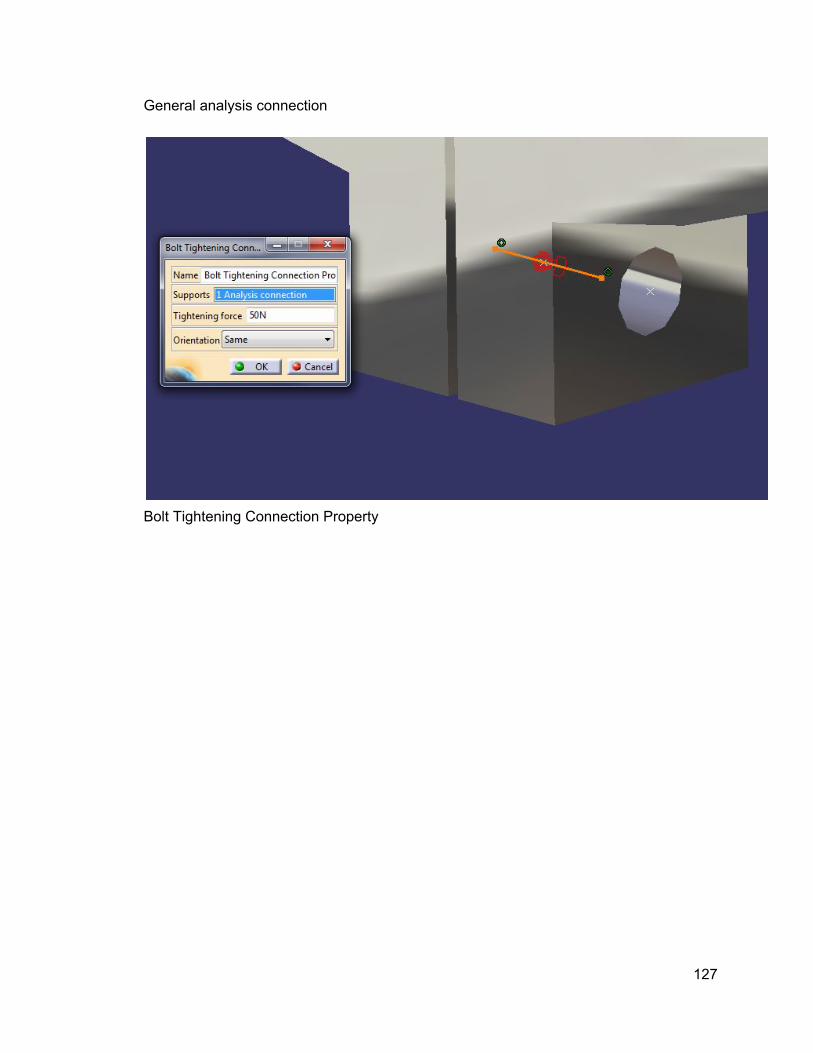
General analysis connection
Bolt Tightening Connection Property
127

Rigid virtual part and clamp
128

Resist translation in y on the mount shoulders
129

Contact connection property between eccentric plate and the two mount components (must have surface contact constraints between plate and mount peices
130
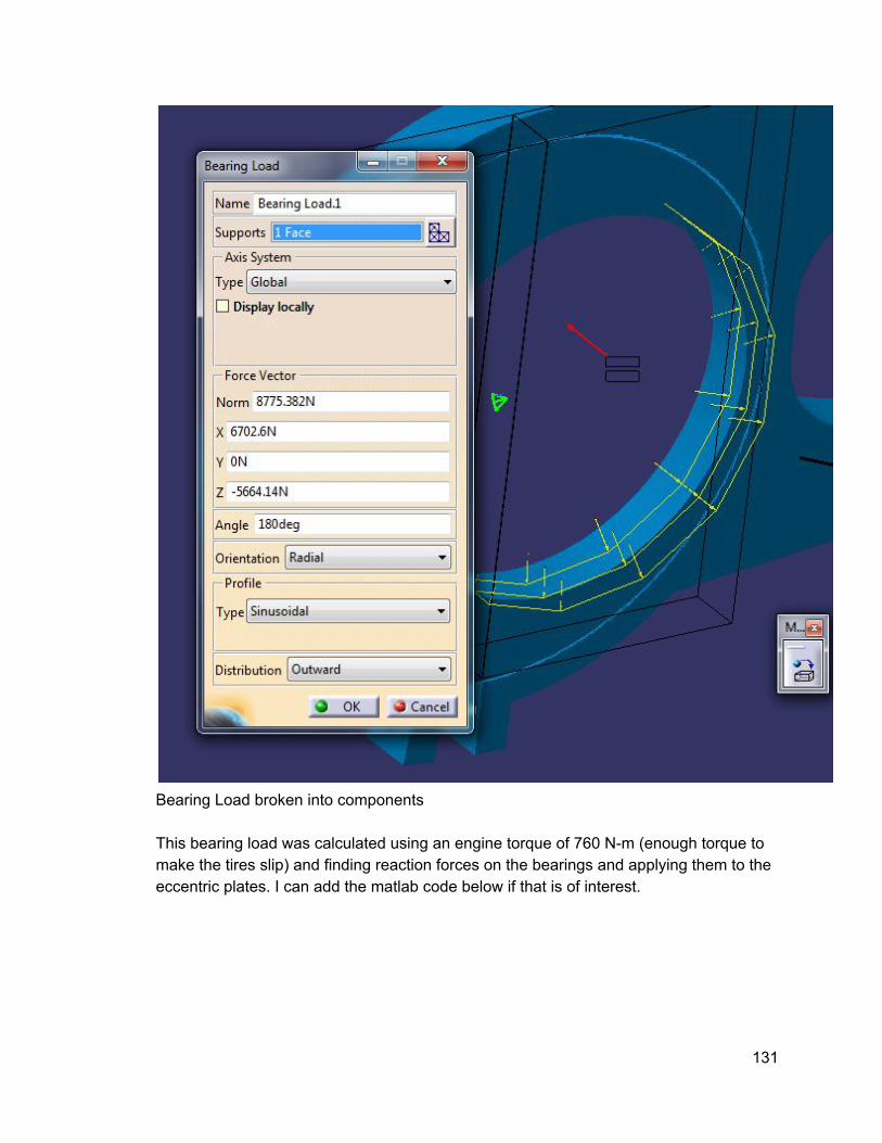
Bearing Load broken into components This bearing load was calculated using an engine torque of 760 Nm (enough torque to make the tires slip) and finding reaction forces on the bearings and applying them to the eccentric plates. I can add the matlab code below if that is of interest.
131

Bolt tightening component did not work. Distributed force added instead with rigid connection of bolt pattern This force was chosen based off the specs for ideal tightening force on an M8 bolt. The M8 bolt was chosen by doing friction analysis between the eccentric plate and the mounting system to figure out the recommended clamping force to prevent slip. Once again matlab code can be added if it is of interest. Output Information Provide an image of the FEA stress results below:
132

First Iteration:
133
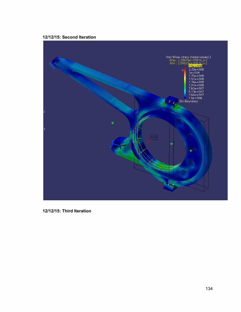
12/12/15: Second Iteration
12/12/15: Third Iteration
134

12/13/15: Fourth Iteration
135

12/16/15: Fifth Iteration
136

Right Side:
137

12/17/15: Sixth Iteration
138

Right Side:
139

Final Design:
140

Right:
141

FEA displacement result:
142

143

Explain the results of your analysis here: The results of my analysis show that this design will uphold the stress from the engine torque with a safety factor of 2 while being lighter than last years design. However, this analysis does not include a study of buckling or lateral forces on the mount. Therefore, some post design phase changes needed to be made. To account for buckling a webbing was added to the long upper pocket of the mount (images to come later). Other design changes include longer tabs on the mount and clamp and changes to the eccentric plate geometry to make it easier to manufacture and to strengthen the bearing wall. Also, an analysis of lateral forces will be included for the FEA of the new design.
144

Appendix C: Implementation of the System
C.1 Sub Section 1‐ Manufacturing In this section of the report any and all content pertaining to how my subsystem was manufactured will be included. This involves any major design changes, and their justifications, that were made to accommodate any unforeseen variables that occurred during build phase of the project. Also, I will post more information on the CNC independent study and how that knowledge was applicable to my project.
C.1.1‐Spool Subsystem
C.1.1.1‐Spool
This was discussed earlier in the report, but changes to the inner and outer diameters of the spool occurred due to the limitations of MTU’s boring bar capabilities. A creaform scan was attempted on the spool but the results were not usable. The hopes were to check how closely the manufactured spool was to the Catia model. The spool came with threads for the CV boot cover plate, saving us the need to helicoil the holes. C.1.1.2Tripod Inserts The inserts were not able to be sent over by Germany so Esco had to help us make the inserts. Due to Esco’s limited availability we had to attempt to precut and heat treat the steel for Esco so all they had to do was the wire EDM process. The drawings made in Germany for the inserts called out either 02 tool steel or 4130. Since 4130 was much easier to find it was chosen as the material to use for the inserts on the cCar. When trying to heat treat the steel we were limited on time so we chose to do a preheat for 2 hours at 677 degrees celsius then cranked up to 871 degrees for 4 hours and oil quenched. These parts were too brittle to work on and broke when
145

machining was attempted. Robert Culbertson at Esco let me know that not annealing the steel after the fact left the material to brittle to work on. In the future, the steel should be annealed between 200 to 420 degrees celsius depending on the properties we want. He also let me know that our quenching container was far too small for steel of that size (3 inches in diameter). This limits the amount OSU can reliably heat treat in the future if the drivetrain inserts continue to be a desired design. Luckily, Robert was able to acquire some H11 tool steel and made inserts for us in time to have a running cCar.
146

147

After sanding the inside and outside of the inserts until the finish was shiny they were pressed in with some green loctite around the outside surfaces of the insert. This was done because the inserts were able to go into the spool a bit too easy and we wanted to make sure the fit was secure. The tripods currently have full travel in all directions in the inserts and will continue to be monitored throughout the season.
C.1.1.3‐Spool Plug Housing Waterjet at RED, thickness was adjusted to meet scrap material found in the shop. The material was also changed to steel due to steel having the correct thickness for the application. Also the geometry of the housing was changed so that there was no lip on the backside to simplify the machining process.
The housing needed to be sanded down to thickness and pressed into the spool. It was crucial to prevent bending in the plug as it was compressed into the spool. There was a balance that needed to be found between sanding it to fit snug and making sure it was able to be pressed without bending. However, any bending can be corrected when pressing in the tripod insert.
C.1.1.4‐Spool Plug This was made using plastic supplied by Igus using the Haas CNC lathe. The plugs needed to be sanded to fit, and a few of the plugs needed to be shaved in length to make sure that halfshaft plunge was similar on the right and left side of the car.
C.1.1.5‐CV Boot Plate Manufactured in Germany and sent over. The plates are able to bend very easy when being taken in and out of the spindle. The picture below shows one of the plates that got bent. This could be avoided by being more careful when pulling the plates out of the spindles. The one below was bent because I used the CV boot material to force the plate
148
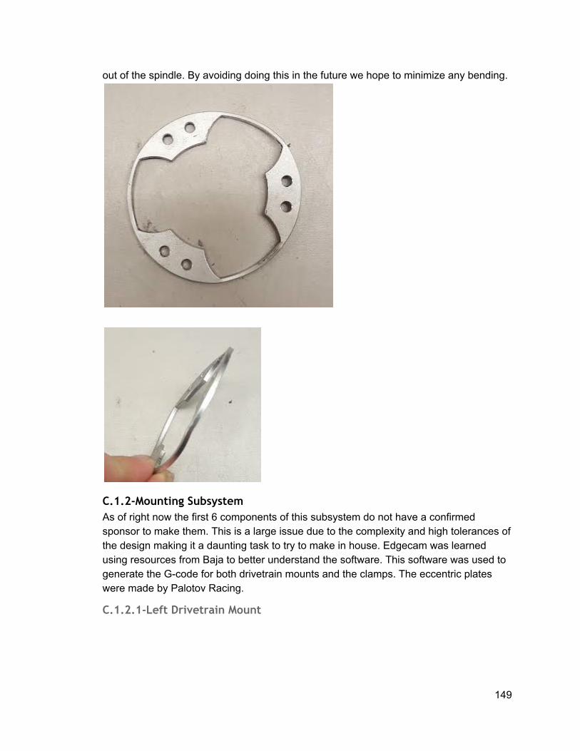
out of the spindle. By avoiding doing this in the future we hope to minimize any bending.
C.1.2‐Mounting Subsystem As of right now the first 6 components of this subsystem do not have a confirmed sponsor to make them. This is a large issue due to the complexity and high tolerances of the design making it a daunting task to try to make in house. Edgecam was learned using resources from Baja to better understand the software. This software was used to generate the Gcode for both drivetrain mounts and the clamps. The eccentric plates were made by Palotov Racing.
C.1.2.1‐Left Drivetrain Mount
149

This mount was made using the CNC machine in Oregon State Universities machine shop. The edgecam code consisted of 3 different operations. One operation to drill the clamp holes, one operation to pocket the webbing on one side and a third operation to machine the rest of the pockets on the other side and machine out the profile. When making different operations it became apparent that having separate save files for each operation made edgecam run smoother and have less of a chance to crash while processing. That being said, defining the stock size and the location of the cpl in each save file must be exactly the same for the machinists to be able to accurately machine the parts. First Operation:
150

151

For the drilling operations a peck drill was used. There was a mistake during coding where the wrong hole diameter was chosen for the clamp holes and required redrilling on a manual mill to fit an M8 bolt. This proved to be advantageous because it left material for a M8 helicoil to be inserted in the top hole of the left mount. Helicoil was not used on the bottom hole because there was enough space for a nut to fit on the back end of the bottom mount hole. When the spare of the drivetrain mounts are made the hole locations are going to be set farther out from the centerline of the mount so that bolt heads and nuts can fit flush to the drivetrain mounts. This will save time by avoiding the need for custom washers and shims to make sure the bolts are clamping properly. Second Operation:
152

One limitation to this operation is that the fillet made by the eight inch ball nose took a long time to make and if I were to redesign the system I would move to a bigger size fillet. This is not only to save time but also because eight inch tools were very easy to break while machining the mount.
153

154

When defining the roughing pass for the webbing the default setting is a waveform cut. This cut can be incredibly slow when machining a lot of material but is used to reduce the wear on the tool while machining. The key to getting the best benefit out of waveform is reducing the feed rate and increasing the depth per cut to 150 percent of the tools diameter. When this strategy was implemented machining time was drastically reduced. Third Operation:
155

156
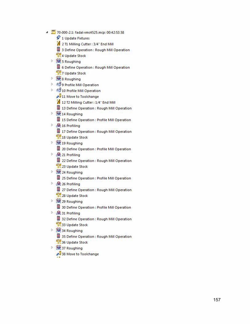
157

Fixturing:
158

159

During design refinement it became apparent that the upper arm of the drivetrain mount is under a lot of bending so a webbing was adding in the pocket with holes in the webbing for weight savings. This makes it so that there is some material to resist buckling in the system. Other pockets were adjusted as well, to insure structural integrity while making sure to keep weight additions below the 510 gram range. For the second set of mounts the left side needs the clamping bolt holes to be higher up so that the bolt head can be flush to the clamp and no shims will have to be made for sufficient clamping. The shims were made using a lathe to turn out a cylindrical piece that was sanded to fit.
C.1.2.2‐Right Drivetrain Mount
160

This is the right drivetrain mount right after it came out of the CNC. This is to show the expected post processing required for each part manufactured in the drivetrain mounting system. The right mount was made in a similar fashion to the left mount so the considerations explained above are applied to this design. Below will be the major features of the edgecam code and some pictures of the different ways the mount was fixtured during machining. The main difference between the left and right mount is that the right mount has helacoil threads on the top and bottom bolt holes. First Operation:
161

Second Operation:
162

Third Operation:
163

164

Fixturing:
165

166

Webbing was added to the right drivetrain mount as well to improve structural integrity. Also, pockets were adjusted with the same idea of only adding less than 510 grams. With this in mind, the right drivetrain mount is under significantly less load than the left so there was less of a need for the webbing or reduction of pocket size.
C.1.2.3‐Left Eccentric Plate
167

The eccentric plates were made by palotov racing, a new sponsor to GFR in 2016. I would recommend using them again as a valuable machining resource and consulting since Dennis Palotov used to be an SAE design judge so he has valuable knowledge that the program could use. To make the eccentric plates he used his cnc in house and made a set of soft jaws to fixture the plate. The plates clamp well in the eccentric but the plates don’t seem to be completely flat. This causes the clamps to not mount square as easily but it is still doable. It would be good, if Dennis machines them again, to have him add extra fixturing so that the part stays flat while each half is machined. Soft Jaw Fixturing:
168

C.1.2.4‐Right Eccentric Plate
169

The right eccentric plate was made in the same fashion as the left one. Similar concerns of how flat it is but clamps easily.
C.1.2.5‐Left Clamp
170

The left clamp was made with a 2 operation edgecam code. The operations are relatively small so keeping them on the same edgecam file did not cause any issues. The first operation is a drilling op and the second operation mills out the inner and outer profile. First Operation:
171

Second Operation:
172

Fixturing:
173

The first part of the second operation requires different fixturing as this but it is relatively simple to clamp onto the outer edges of the stock. The fixturing shown above is done for the second half of the second operation. When machining this part there were issues with the edgecam code not leaving a proper lip inside the clamp. This issue was because the stock height was not the same in the code as the stock we were using to machine the part. The preferred method would be to have the stock height the same height as the part and do a facing operation manually before starting to run the code. For the spare clamp the holes will need to be moved up (same amount as the mount) to make it so the bolt head will be flush and there will be no shim required for sufficient clamping.
C.1.2.6‐Right Clamp
174
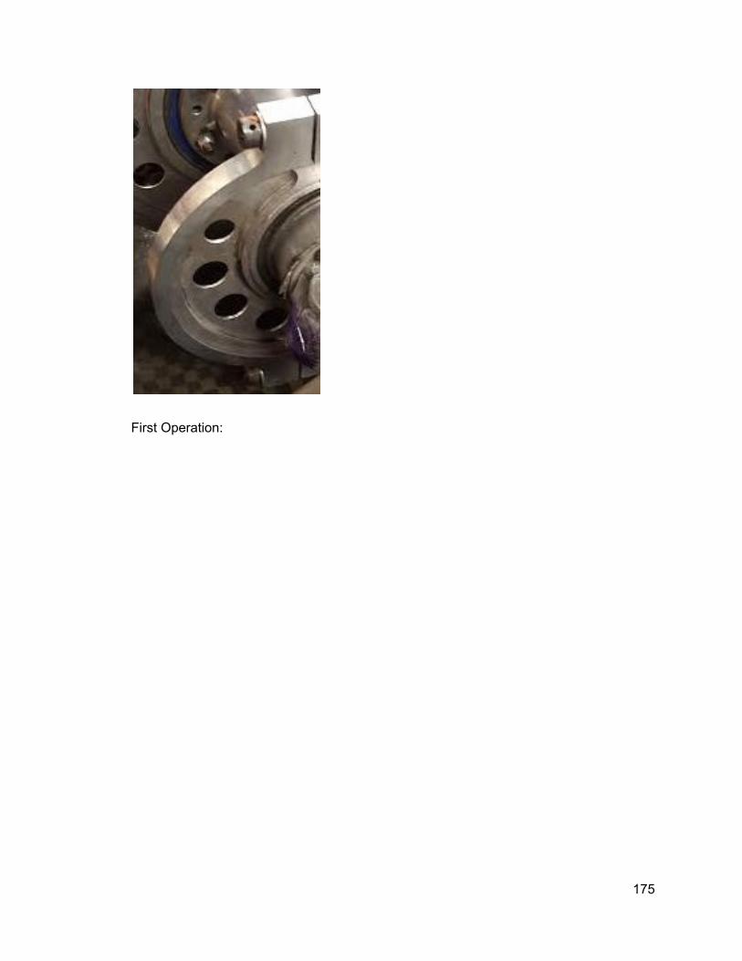
First Operation:
175

Second Operation:
176

Fixturing:
177

The first part of the second operation requires different fixturing as this but it is relatively simple to clamp onto the outer edges of the stock. The fixturing shown above is done for the second half of the second operation. The right clamp does not require any redesign for the second set nor did it have the same issues the left clamp did during machining.
C.1.2.7‐Engine Mount Spacers The engine mount spacers had to change due to the engine mounts being slightly moved during installation. Parts were made on the lathe and sanded to fit the spaces necessary.
This is the original configuration of the spacers for the drivetrain. Another spacer was added to the right side of the lower bolt (with respect to the above picture) with a thickness of 5 mm to accommodate for the engine moving.
C.1.2.8‐Engine Mount Bolts
178

These are being made by Gary in house with Titanium. Gary took a long time to make these bolts and retired this year. Next year an alternate solution will need to be found. Since Gary took a long time to make the top bolt an alternative solution was made out of aluminum. The aluminum solution was a rod with internal threads where two M6 bolts were bolted in to secure the system. Unfortunately, during testing, skidpad more specifically, the aluminum bolt sheared on both ends. Luckily, nothing in else in the system suffered damage from this, but a hole was punctured in the diffuser. The pictures below illustrate the damage done to the aluminum rod.
179

A similar design to the one shown above was used in the 2015 car as well but did not fail like this one did on the 2016 car. There are a few reasons for this. One reason is that the left mount on the 2016 design has to be pulled extremely tight to get the bolt through, this means there is constant stress on the bolt. Furthermore, with this year's design the right mount has a gap between it and the engine where the bolt is cantilevered out from its sheath (picture shown below) so the bolt must be made out of something stronger to work with this new design.
Luckily, Gary was able to eventually finish the top bolt so it was able to be installed (picture shown above) as a replacement for the aluminum rod. A custom washer had to be made since the bolt was made long. Top Bolt:
Bottom Bolt:
180

5.1.3‐HalfShaft Subsystem
C.1.3.1‐Shaft The half shafts this year were ordered from Taylor Race. The diameters of the halfshafts changed so a new spring had to be ordered. The spring was ordered from McmasterCarr. The spring was two inches long with a half inch OD and it was made out of .063 zinc plated piano wire.
C.1.3.2‐Tripod Ordered from Taylor Race, they seem slightly different from last year’s tripods but I am not sure how that changes their functionality. The pictures below will compare the tripods.
C.1.3.3‐Plugs, Stoppers The plugs, and stoppers were all made on the Haas CNC Lathe this year. Blue Igus plastic was used to make the plugs, more material will need to be ordered for next year.
181

The stoppers were made out of aluminum round stock and made larger than a half an inch for a light press fit.
C.1.4‐Chain and Sprocket
C.1.4.1‐ Sprocket Ordered from Superior Sprockets, only a 38 tooth sprocket was ordered since that is the preferred ratio is 11/38. There have been issues getting a hold of superior sprockets and getting them to send us the sprocket we need. There was a spare from last season that is installed on the 2016 car but the spare still needs to be delivered by the sponsor. The drive sprocket was ordered from Summit Racing and has 11 teeth.
182

C.1.4.2‐Chain Ordered from RK Excel, chain changed to 2014 chain (520MXU). The chain was ordered gold plated and is a lighter chain that does not need to be greased as often as the MXZ chain. C.1.4.3Chain Guard The chain guard was made out of leftover laser cut steel from Warn. New steel will need to be ordered since the rest of the steel we have is not the correct thickness to be used as a chain guard. The chain guard design was changed this year to be a two piece system. The rear piece mounts to the diffuser and goes up and through the hardpoint that has the opening for the left drivetrain mount. The interior piece of the chainguard mounts to the engine’s stock chainguard and the inside of the chassis (through a hole made in a hardpoint).
C.2‐Post Processing/Assembly
C.1.1‐Spool Subsystem
More constant contact with Germany is recommended for next year so issues will be uncovered sooner. Issues with lack of communication of delays in German made parts for the spool system.
C.2.1.1‐Spool Issues with MTU’s material sponsor giving them material late. Should look into American sponsors for spool next year or supplying MTU with material next year to avoid the issue. The spool did not require any post processing, MTU added threads for the CV boot cover plates so the spool was ready to use on arrival. The bearings were pressed in using thin walled metal cylinders that were the diameter of the bearings. The right bearing was easier to install than the left, for the left bearing the spool was frozen so that the bearing slid on easier. C.2.1.2Tripod Inserts The inserts needed to be lightly sanded to remove any carbon stuck to the insert. The insert should have a shine to it and the tripod should not stick anywhere inside the insert. Sanding the outside of the insert was purely for cleaning, now sanding had to be done to get it to fit. Loctite was coated on the outside of the insert before it was pressed in. To press in the insert it was hand pressed into the spool until it was horizontal. Then a plate was put on top of the insert and the hydraulic press was used to press it the rest of the way in. Make sure the spool plug housing is put into the spool before pressing in the tripod inserts.
C.2.1.3‐Spool Plug Housing
183

The housing needed to be sanded to a smooth outer edge so it would not scratch the inside of the spool. It should not require significant force to press the housing into the spool, the housing could bend if too much force was used to install it.
C.2.1.4‐Spool Plug This needed to be sanded to fit inside of the housing. Make sure it does take some effort to get the plastic in the housing, a loose fit could cause damage to the spool.
C.2.1.5‐CV Boot Plate Will be mounted on last once tripods and half shafts are attached to spool. The six M3 bolts require a long time to take in and out of the spool and spindles. Three bolts would make a lot more sense to reduce the time to do maintenance on the system.
C.2.2‐Mounting Subsystem
C.2.2.1‐Left Drivetrain Mount This mount needed to be deburred and filed so that it did not have any sharp edges that could cut any wires or tubing that might be near it during install. Also, the top mounting bolt hole needed to be tapped and helicoiled. Make sure that the tapping tool is parallel with the hole so that the threads are made properly, if not the clamps will not align properly. Washers and shims had to be sanded to fit so that the bolts and lock nut were clamping properly. The last step was polishing the mount before installing it in the car. The left mount had difficulties lining up with the upper engine mount but with some force and a hammer the upper bolt was able to be pushed through. C.2.2.2Right Drivetrain Mount This mount also needed to be deburred, sanded and polished before being installed. The top and bottom mount holes needed to be tapped and helicoiled but no shims were required since the bolts were able to fit flush against the mount.
C.2.2.3‐Left Eccentric Plate The eccentric plates did not require any sanding or deburring after being received from Dennis Palotov. The plates were pressed onto the spool in the same fashion as the bearings using the shoulder of the plate.
C.2.2.4‐Right Eccentric Plate This plate was in the same condition as the left plate and went on the spool in the exact same fashion.
184
C.2.2.5‐Left Clamp The clamp needed to be deburred and polished before installation. The clamp is bolted onto the mount by tightening the top bolt first then the bottom bolt so that chain tension is preserved.
C.2.2.6‐Right Clamp This clamp needed to be deburred and polished before installation. It is also installed in the same way as the left clamp.
C.2.2.7‐Engine Mount Spacers The spacers were deburred to remove any sharp corners. They were held in location while the engine mounting bolts were threaded through them and the drivetrain mounts.
C.2.2.8‐Engine Mount Bolts The bottom engine bolt was inserted first then the top bolt.
C.2.3‐HalfShaft Subsystem
C.2.3.1‐Shaft The shaft needed the aluminum spring stopper pressed in the amount calculated based on the amount of halfshaft plunge desired. Then the tripods and circlips were put on and the springs and plugs pushed in.
185

5.2.3.2‐Tripod The tripod was put on with a circlip.
5.2.3.3‐Plugs, Stoppers The stoppers were pressed in, as mentioned above, and the plugs were sanded to fit and pushed in afterward. The right plug needed to be sanded down so that the right side plunge matched the left side plunge.
5.2.4‐Chain and Sprocket
5.2.4.1‐ Sprocket
186
The sprocket needs the teeth ground and for it to be anodized before being installed on the spool.
5.2.4.2‐Chain The chain needed to be broken so that it could be put on the car and measured to see how many links needed to be taken out. Once the links were removed the chain was put on using the master link and the tension was set by rotating the eccentric plates.
5.2.4.3‐Chain Guard The chain guard needed to be cleaned and filed so that it had smooth welding surfaces and no sharp edges for things to be cut on during installation. For the interior chain guard the chassis bolt needs to be threaded through before the other bolt so that the chain guard is secured properly. A potted insert needed to be put in the diffuser for the rear piece of the chain guard, make sure the hold for the insert is drilled after the tabs of the chain guard are welded on.
187