BW10 - konsument.danfoss.comkonsument.danfoss.com/PCMFiles/5/Heat_Pumps/BW10.pdf · The CCN clock...
28
Water-Sourced Heat Pumps with or without Integrated Hydronic Module BW10 Nominal cooling capacity 24-95 kW Nominal heating capacity 30-116 kW BW10 - optimised for heating • High temperature up to +65°C • Evaporator temperature down to -5°C • Needle valve control of domestic hot water - - Detail view of the variable-speed pump The new generation of BW10 heat pumps was designed for commercial applications (offices, hotels etc.), residential applications (houses, apartments etc.) or industrial applications (low-temperature cooling or domestic hot-water production etc.). The BW10 units were especially designed for heating applications with a leaving water temperature of 65°C (without supplementary heating) and a COP of above 5. A large number of options is available for both versions: - hydronic kits with or without variable water flow rate, - reinforced sound insulation, - stacking and connection of two units, or operation with low-temperature glycol solution down to -12°C. This product range offers a unique combination of high performance and functionality in an exceptionally compact chassis. Features • Reduced footprint • R-410A scroll compressor • Variable-flow pump • Low-noise option (-3 dB(A)) • Stacking of two units for increased capacity • Compatible communication protocols: JBus, BacNet, LON • Water connection at the top or rear Standard unit Unit with optional hydronic module VDGFK102
-
Upload
nguyennguyet -
Category
Documents
-
view
218 -
download
1
Transcript of BW10 - konsument.danfoss.comkonsument.danfoss.com/PCMFiles/5/Heat_Pumps/BW10.pdf · The CCN clock...
Water-Sourced Heat Pumpswith or without Integrated Hydronic Module
BW10Nominal cooling capacity 24-95 kW
Nominal heating capacity 30-116 kW
BW10 - optimised for heating• Hightemperatureupto+65°C• Evaporatortemperaturedownto-5°C• Needlevalvecontrolofdomestichotwater
--
Detail view of the variable-speed pump
ThenewgenerationofBW10heatpumpswasdesignedforcommercialapplications(offices,hotelsetc.),residentialapplications(houses,apartmentsetc.)orindustrialapplications(low-temperaturecoolingordomestichot-waterproductionetc.).
TheBW10unitswereespeciallydesignedforheatingapplicationswithaleavingwatertemperatureof65°C(withoutsupplementaryheating)andaCOPofabove5.
Alargenumberofoptionsisavailableforbothversions:- hydronickitswithorwithoutvariablewaterflowrate,- reinforcedsoundinsulation,- stackingandconnectionoftwounits,oroperationwithlow-temperatureglycolsolutiondownto-12°C.Thisproductrangeoffersauniquecombinationofhighperformanceandfunctionalityinanexceptionallycompactchassis.
Features• Reducedfootprint• R-410Ascrollcompressor• Variable-flowpump• Low-noiseoption(-3dB(A))• Stackingoftwounitsforincreasedcapacity• Compatiblecommunicationprotocols:JBus,BacNet,LON• Waterconnectionatthetoporrear
Standard unit
Unit with optional hydronic module
VDGFK102
2
The right unit for any application• ThehightemperatureoftheBW10unitsmakesthem
compatiblewithmostheatsources,bothinnewandrefurbishedbuildingsandpermitsdomestichotwaterproductioninsignificantquantities(dualsetpoint).
• TheBW10usesweathercompensationcontrolandcontrolsfoursupplementaryelectricheatingstagesorareliefboiler.
• Option157(heatingsystemmanager)allowscontrolofsystemswithseveralheatsourcesanddifferentsupplement-arysystems:electricheat,boilerordistrictheatingforthemostcomplexsystems.
Adaptability and simple installation• Completehydronickitforbothevaporatorandcondenserwith
differentlevelsofavailablepressure,withvariableorfixedspeed(seephotosonthefollowingpages).
• Needlevalvecontrolforeasiertransitionfromthecomfortmodetodomestichotwaterproductionusingacollectiontank(notsupplied)
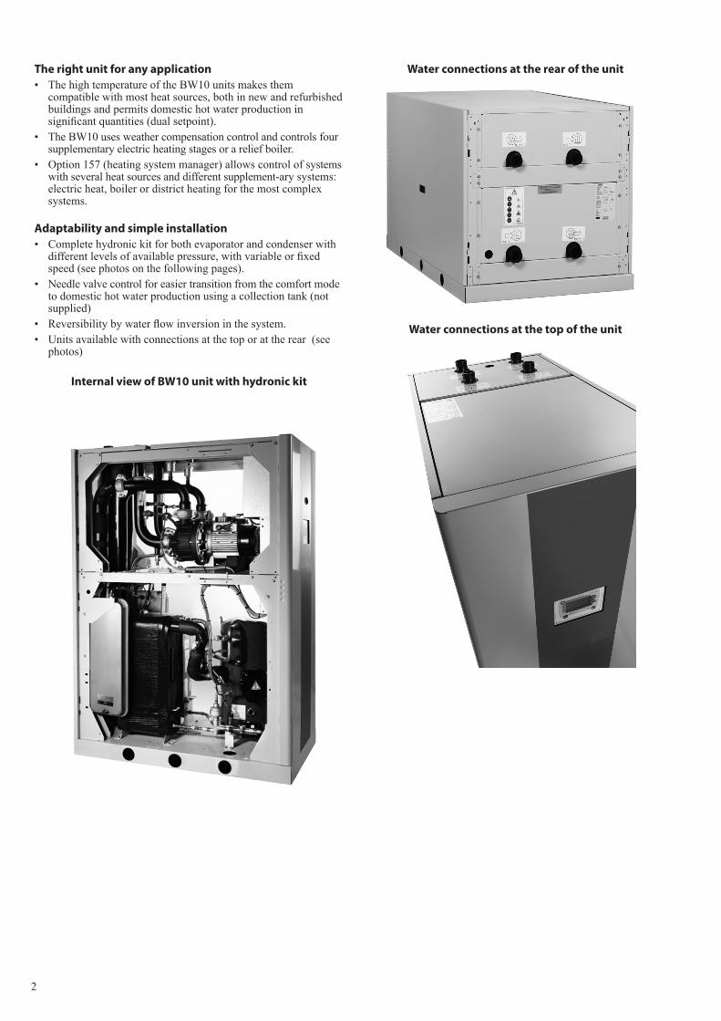
• Reversibilitybywaterflowinversioninthesystem.• Unitsavailablewithconnectionsatthetoporattherear(see
photos)
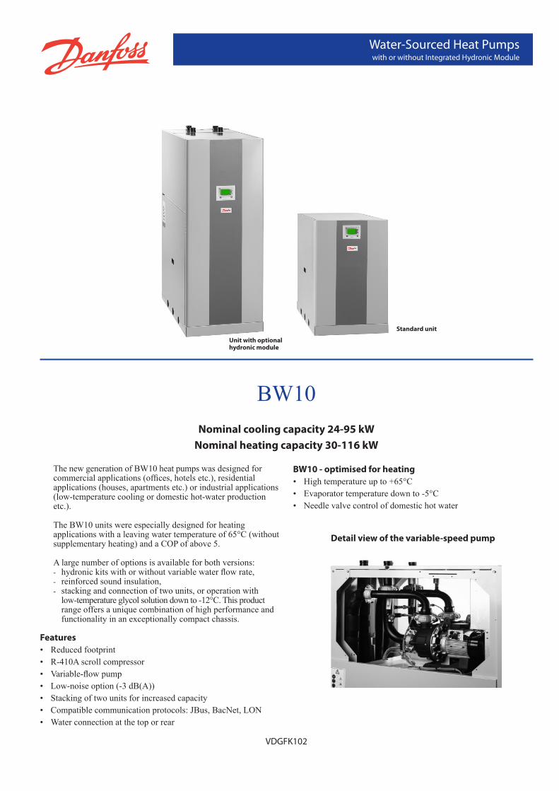
Internal view of BW10 unit with hydronic kit
Water connections at the top of the unit
Water connections at the rear of the unit
3
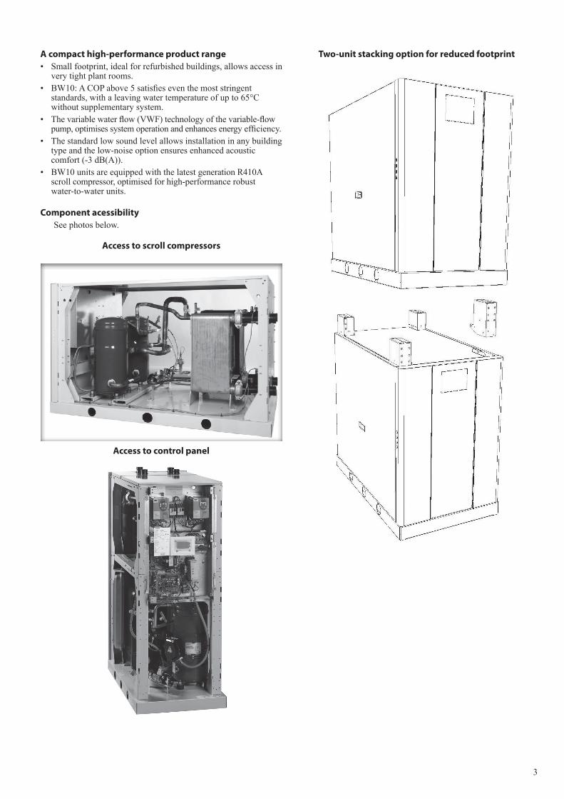
Two-unit stacking option for reduced footprint
Access to control panel
A compact high-performance product range• Smallfootprint,idealforrefurbishedbuildings,allowsaccessin
verytightplantrooms.• BW10:ACOPabove5satisfieseventhemoststringent
standards,withaleavingwatertemperatureofupto65°Cwithoutsupplementarysystem.
• Thevariablewaterflow(VWF)technologyofthevariable-flowpump,optimisessystemoperationandenhancesenergyefficiency.
• Thestandardlowsoundlevelallowsinstallationinanybuildingtypeandthelow-noiseoptionensuresenhancedacousticcomfort(-3dB(A)).
• BW10unitsareequippedwiththelatestgenerationR410Ascrollcompressor,optimisedforhigh-performancerobustwater-to-waterunits.
Component acessibilitySeephotosbelow.
Access to scroll compressors
4
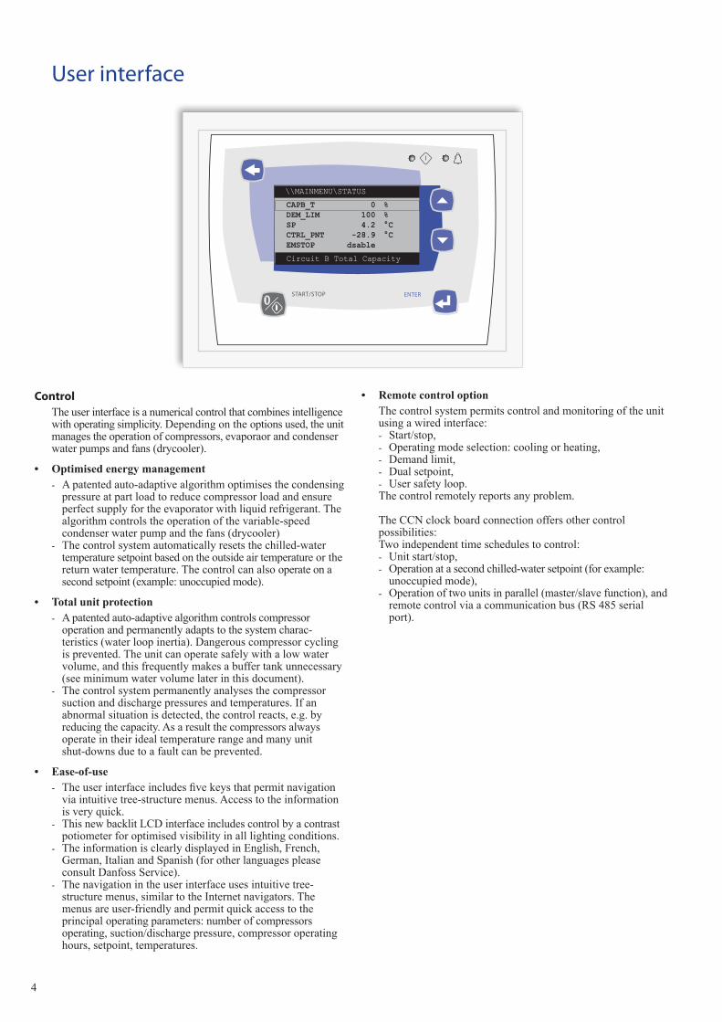
ControlTheuserinterfaceisanumericalcontrolthatcombinesintelligencewithoperatingsimplicity.Dependingontheoptionsused,theunitmanagestheoperationofcompressors,evaporaorandcondenserwaterpumpsandfans(drycooler).
• Optimisedenergymanagement- Apatentedauto-adaptivealgorithmoptimisesthecondensingpressureatpartloadtoreducecompressorloadandensureperfectsupplyfortheevaporatorwithliquidrefrigerant.Thealgorithmcontrolstheoperationofthevariable-speedcondenserwaterpumpandthefans(drycooler)
- Thecontrolsystemautomaticallyresetsthechilled-watertemperaturesetpointbasedontheoutsideairtemperatureorthereturnwatertemperature.Thecontrolcanalsooperateonasecondsetpoint(example:unoccupiedmode).
• Totalunitprotection- Apatentedauto-adaptivealgorithmcontrolscompressoroperationandpermanentlyadaptstothesystemcharac-teristics(waterloopinertia).Dangerouscompressorcyclingisprevented.Theunitcanoperatesafelywithalowwatervolume,andthisfrequentlymakesabuffertankunnecessary(seeminimumwatervolumelaterinthisdocument).
- Thecontrolsystempermanentlyanalysesthecompressorsuctionanddischargepressuresandtemperatures.Ifanabnormalsituationisdetected,thecontrolreacts,e.g.byreducingthecapacity.Asaresultthecompressorsalwaysoperateintheiridealtemperaturerangeandmanyunitshut-downsduetoafaultcanbeprevented.
• Ease-of-use- Theuserinterfaceincludesfivekeysthatpermitnavigationviaintuitivetree-structuremenus.Accesstotheinformationisveryquick.
- ThisnewbacklitLCDinterfaceincludescontrolbyacontrastpotiometerforoptimisedvisibilityinalllightingconditions.
- TheinformationisclearlydisplayedinEnglish,French,German,ItalianandSpanish(forotherlanguagespleaseconsultDanfossService).
- Thenavigationintheuserinterfaceusesintuitivetree-structuremenus,similartotheInternetnavigators.Themenusareuser-friendlyandpermitquickaccesstotheprincipaloperatingparameters:numberofcompressorsoperating,suction/dischargepressure,compressoroperatinghours,setpoint,temperatures.
\\MAINMENU\STATUS
Circuit B Total Capacity
CAPB_T 0 %DEM_LIM 100 %SP 4.2 °CCTRL_PNT -28.9 °CEMSTOP dsable
ENTERSTART/STOP
User interface
• RemotecontroloptionThecontrolsystempermitscontrolandmonitoringoftheunitusingawiredinterface:- Start/stop,- Operatingmodeselection:coolingorheating,- Demandlimit,- Dualsetpoint,- Usersafetyloop.Thecontrolremotelyreportsanyproblem.
TheCCNclockboardconnectionoffersothercontrolpossibilities:Twoindependenttimeschedulestocontrol:- Unitstart/stop,- Operationatasecondchilled-watersetpoint(forexample:unoccupiedmode),
- Operationoftwounitsinparallel(master/slavefunction),andremotecontrolviaacommunicationbus(RS485serialport).
5
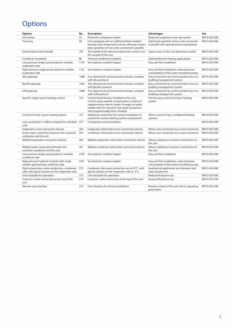
OptionsOptions No. Description Advantages UseSoft starter 25 Electronic compressor starter Reduced compressor start-up current BW10 020-090 Twinning 58 Unit equipped with an additional field-installed
leaving water temperature sensor, allowing master/slave operation of two units connected in parallel.
Optimised operation of two units connected in parallel with operating time equalisation
BW10 020-090
External disconnect handle 70F The handle of the electrical disconnect switch is on the outside of the unit
Quick access to the unit disconnect switch BW10 020-090
Condenser insulation 86 Thermal condenser insulation Optimisation for heating applications BW10 020-090Low-pressure single-pump hydronic module, evaporator side
116F See hydronic module chapter Easy and fast installation BW10 020-090
High-pressure single-pump hydronic module, evaporator side
116J See hydronic module chapter Easy and fast installation, reduced power consumption of the water circulation pump.
BW10 020-090
JBus gateway 148B Two-directional communications board, complies with JBus protocol
Easy connection by communication bus to a building management system
BW10 020-090
BacNet gateway 148C Two-directional communications board, complies with BacNet protocol
Easy connection by communication bus to a building management system
BW10 020-090
LON gateway 148D Two-directional communications board, complies with LON protocol
Easy connection by communication bus to a building management system
BW10 020-090
Specific single-source heating control 153 Control board factory-installed on the unit, control using weather compensation, control of supplementary electric heater (4 stages) or boiler, needle valve for domestic hot-water production with programmable time schedule.
Permits easy control of a basic heating system
BW10 020-090
Control of multi-source heating system 157 Additional control box for remote installation to control the various heating system components
Allows control of pre-configured heating systems
BW10 020-090
Low sound level (-3 dB(A) compared to standard unit)
257 Compressor sound insulation BW10 020-090
Evaporator screw connection sleeves 264 Evaporator inlet/outlet screw connection sleeves Allows unit connection to a screw connector BW10 020-090Screw water connection between the customer condenser and the unit
265 Condenser inlet/outlet screw connection sleeves Allows unit connection to a screw connector BW10 020-090
Welded evaporator connection sleeves 266 Welded evaporator inlet/outlet connection sleeves Allows welding of customer connections to the unit
BW10 020-090
Welded water connection between the customer condenser and the unit
267 Welded condenser inlet/outlet connection sleeves Allows welding of customer connections to the unit
BW10 020-090
Low-pressure single-pump hydronic module, condenser side
270F See hydronic module chapter Easy and fast installation BW10 020-090
High-pressure hydronic module with single variabe-speed pump, condenser side
270J See hydronic module chapter Easy and fast installation, reduced power consumption of the water circulation pump.
BW10 020-090
High-temperature water production, condenser side, with glycol solution on the evaporator side
272 Condenser side water production up to 65°C, with glycol solution on the evaporator side to -5°C
Geothermal application and domestic hot-water production
BW10 020-090
Unit stackable for operation 273 Unit stackable for operation Reduced footprint size BW10 020-090Customer water connection at the top of the unit
274 Customer water connection at the top of the unit Reduced footprint size BW10 020-090
Remote user interface 275 User interface for remote installation Remote control of the unit and its operating parameters
BW10 020-090
6
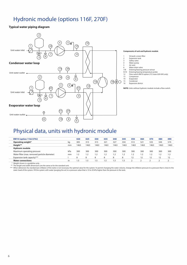
Hydronic module (options 116F, 270F)Typical water piping diagram
Components of unit and hydronic module
1 Victaulic screen filter2 Expansion tank3 Safety valve4 Water pump5 Air vent6 Water drain valve7/8 Entering/leaving pressure sensor9/10 Entering/leaving temperature probe12 Flow switch BW10 option 272 (sizes 020-045 only)13 Compressor14 Evaporator15 Condenser16 Expansion device
NOTE: Units without hydronic module include a flow switch.
2
6
15
10
9
8
5 1
3
4
7
6
14
9
8
5 1
2
4
PT
PT TT
TT
PT
PT TT
13 16
TT
12
3 7
10
6
6
Unit water inlet
Condenser water loop
Unit water outlet
Unit water inlet
Unit water outlet
Evaporator water loop
Physical data, units with hydronic moduleBW10 (option 116J/270J) 020 025 030 035 040 045 050 060 070 080 090Operating weight* kg 305 313 313 321 327 334 513 521 533 544 574Height** mm 1463 1463 1463 1463 1463 1463 1463 1463 1463 1463 1463Hydronic moduleMaximum operating pressure kPa 300 300 300 300 300 300 300 300 300 300 300Water filter (max. removed particle diameter) mm 1.2 1.2 1.2 1.2 1.2 1.2 1.2 1.2 1.2 1.2 1.2Expansion tank capacity*** l 8 8 8 8 8 8 12 12 12 12 12Water connections in 1.5 1.5 1.5 1.5 1.5 1.5 2 2 2 2 2
* Weight shown is a guideline only. . ** The length and width dimensions are the same as for the standard unit. *** When delivered, the standard pre-inflation of the tanks is not necessary the optimal value for the system. To permit changing the water volume, change the inflation pressure to a pressure that is close to the
static head of the system. Fill the system with water (purging the air) to a pressure value that is 10 to 20 kPa higher than the pressure in the tank.
7
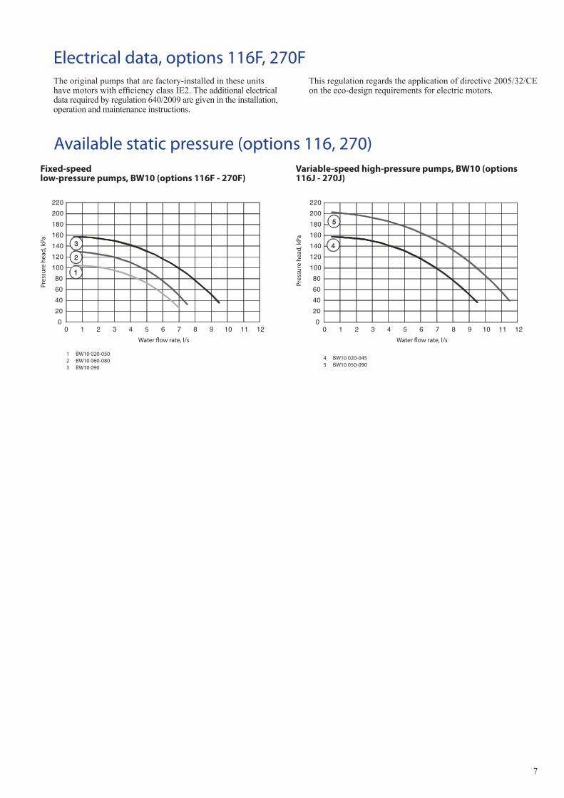
Electrical data, options 116F, 270F
Available static pressure (options 116, 270)Variable-speed high-pressure pumps, BW10 (options 116J - 270J)
Pres
sure
hea
d, k
Pa
Water flow rate, l/s
1 BW10 020-050 2 BW10 060-0803 BW10 090
020406080
100120140160180200220
0 1 2 3 4 5 6 7 8 9 10 11 12
1
2
3
020406080
100120140160180200220
4
5
0 1 2 3 4 5 6 7 8 9 10 11 12
4 BW10 020-045 5 BW10 050-090
Pres
sure
hea
d, k
Pa
Water flow rate, l/s
Fixed-speed low-pressure pumps, BW10 (options 116F - 270F)
Theoriginalpumpsthatarefactory-installedintheseunitshavemotorswithefficiencyclassIE2.Theadditionalelectricaldatarequiredbyregulation640/2009aregivenintheinstallation,operationandmaintenanceinstructions.
Thisregulationregardstheapplicationofdirective2005/32/CEontheeco-designrequirementsforelectricmotors.
8
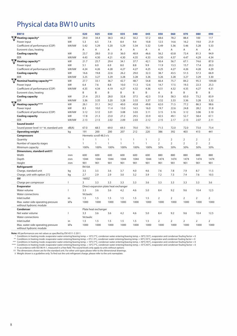
Physical data BW10 unitsBW10 020 025 030 035 040 045 050 060 070 080 090Heating capacity* kW 29.0 34.4 38.3 44.2 50.2 57.2 68.6 78.2 88.4 100 117Power input kW 5.3 6.5 7.4 8.4 9.4 10.8 12.5 14.6 16.2 19.0 21.9Coefficient of performance (COP) kW/kW 5.42 5.29 5.20 5.29 5.34 5.32 5.49 5.36 5.46 5.28 5.33Eurovent class, heating A A A A A A A A A A ACooling capacity kW 23.7 28.0 31.0 36.0 40.9 46.6 56.2 63.8 72.4 81.3 94.9EER kW/kW 4.43 4.30 4.21 4.30 4.35 4.33 4.50 4.37 4.47 4.29 4.34Heating capacity** kW 21.7 25.7 29.4 34.1 37.7 42.1 50.4 56.7 67.1 74.6 87.0Power input kW 5.1 6.0 6.9 8.0 8.8 9.9 11.9 13.3 15.7 17.4 20.3Coefficient of performance (COP) kW/kW 4.24 4.26 4.28 4.27 4.27 4.25 4.25 4.27 4.26 4.28 4.29Cooling capacity kW 16.6 19.8 22.6 26.2 29.0 32.3 38.7 43.5 51.5 57.3 66.9EER kW/kW 3.25 3.27 3.29 3.28 3.28 3.26 3.26 3.28 3.27 3.29 3.30Nominal heating capacity*** kW 27.7 33.1 36.7 42.7 48.7 54.8 66.4 75.7 84.2 95.3 109.00Power input kW 6.4 7.6 8.8 10.0 11.3 12.6 14.7 17.5 19.3 22.3 25.3Coefficient of performance (COP) kW/kW 4.35 4.34 4.19 4.27 4.32 4.36 4.51 4.32 4.35 4.27 4.31Eurovent class, heating B B B B B B A B B B BCooling capacity kW 21.4 25.5 28.0 32.8 37.5 42.3 51.8 58.3 65.0 73.2 83.9EER kW/kW 3.36 3.35 3.20 3.28 3.33 3.37 3.52 3.33 3.36 3.28 3.32Heating capacity**** kW 26.1 31.1 34.2 40.0 43.8 49.8 62.0 71.5 77.2 86.3 98.6Power input kW 8.3 10.0 11.4 13.0 14.5 16.0 19.7 22.6 24.8 28.2 31.8Coefficient of performance (COP) kW/kW 3.12 3.12 3.01 3.08 3.03 3.11 3.15 3.16 3.12 3.06 3.10Cooling capacity kW 17.8 21.3 23.0 27.2 29.5 33.9 42.5 49.1 52.7 58.4 67.1EER kW/kW 2.13 2.13 2.02 2.09 2.03 2.12 2.15 2.17 2.13 2.07 2.11Sound levels†Sound power level 10-12 W, standard unit dB(A) 67.0 68.5 69.0 69.3 70.0 70.1 71.5 72.0 72.0 73.0 73.4Operating weight kg 191 200 200 207 212 220 386 392 403 413 441Compressors Hermetic scroll 48.3 r/sQuantity 1 1 1 1 1 1 2 2 2 2 2Number of capacity stages 1 1 1 1 1 1 2 2 2 2 2Minimum capacity % 100% 100% 100% 100% 100% 100% 50% 50% 50% 50% 50%Dimensions, standard unit††Width mm 600 600 600 600 600 600 880 880 880 880 880Depth mm 1044 1044 1044 1044 1044 1044 1474 1474 1474 1474 1474Height mm 901 901 901 901 901 901 901 901 901 901 901Refrigerant‡ R410ACharge, standard unit kg 3.5 3.5 3.6 3.7 4.0 4.6 7.6 7.8 7.9 8.7 11.5Charge, unit with option 272 kg 2.7 2.9 2.9 3.0 3.2 3.9 7.2 7.3 7.4 7.6 10.5Oil 160SZCharge per compressor l 3 3.3 3.3 3.3 3.3 3.6 3.3 3.3 3.3 3.3 3.6Evaporator Direct-expansion plate heat exchangerWater volume l 3.3 3.6 3.6 4.2 4.6 5.0 8.4 9.2 9.6 10.4 12.5Water connections VictaulicInlet/outlet in 1.5 1.5 1.5 1.5 1.5 1.5 2 2 2 2 2Max. water-side operating pressure without hydronic module
kPa 1000 1000 1000 1000 1000 1000 1000 1000 1000 1000 1000
Condenser Plate heat exchangerNet water volume l 3.3 3.6 3.6 4.2 4.6 5.0 8.4 9.2 9.6 10.4 12.5Water connections VictaulicInlet/outlet in 1.5 1.5 1.5 1.5 1.5 1.5 2 2 2 2 2Max. water-side operating pressure without hydronic module
kPa 1000 1000 1000 1000 1000 1000 1000 1000 1000 1000 1000
Note: All performances are net values as specified by EN14511-3 2011. * Conditions in heating mode: evaporator water entering/leaving temp. = 10°C/7°C, condenser water entering/leaving temp. = 30°C/35°C, evaporator and condenser fouling factor = 0 ** Conditions in heating mode: evaporator water entering/leaving temp. = 0°C/-3°C, condenser water entering/leaving temp. = 30°C/35°C, evaporator and condenser fouling factor = 0 *** Conditions in heating mode: evaporator water entering/leaving temp. = 10°C/7°C, condenser water entering/leaving temp. = 40°C/45°C, evaporator and condenser fouling factor = 0 **** Conditions in heating mode: evaporator water entering/leaving temp. = 10°C/7°C, condenser water entering/leaving temp. = 55°C/65°C, evaporator and condenser fouling factor = 0 † In accordance with ISO 9614-1, measured in a free field. The sound levels only apply to units without options †† The dimensions shown are for the standard unit. For other unit types please refer to the dimensional drawings. ‡ Weight shown is a guideline only. To find out the unit refrigerant charge, please refer to the unit nameplate.
9
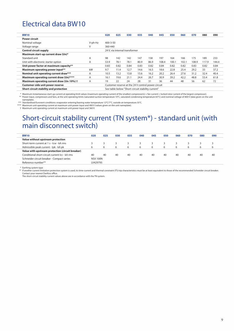
Electrical data BW10BW10 020 025 030 035 040 045 050 060 070 080 090Power circuitNominal voltage V-ph-Hz 400-3-50Voltage range V 360-440Control circuit supply 24 V, via internal transformerMaximum start-up current draw (Un)*Standard unit A 98 142 142 147 158 197 164 166 175 189 233Unit with electronic starter option A 53.9 78.1 78.1 80.9 86.9 108.4 100.1 102.1 108.9 117.9 144.4Unit power factor at maximum capacity** 0.83 0.82 0.84 0.83 0.82 0.84 0.82 0.82 0.83 0.82 0.84Maximum operating power input** kW 9.7 11.4 12.7 14.6 16.5 18.6 22.8 25.4 29.2 33 37.2Nominal unit operating current draw*** A 10.5 13.2 13.8 15.6 16.2 20.2 26.4 27.6 31.2 32.4 40.4Maximum operating current draw (Un)**** A 16.1 19.6 21.1 24.4 26.7 30.9 39.2 42.2 48.8 53.4 61.8Maximum operating current draw (Un-10%) † A 19 22 24 28 31 36 44 48 56 62 72Customer-side unit power reserve Customer reserve at the 24 V control power circuitShort-circuit stability and protection See table below "Short-circuit stability current"
* Maximum instantaneous start-up current at operating limit values (maximum operating current of the smallest compressor(s) + fan current + locked rotor current of the largest compressor). ** Power input, compressors and fans, at the unit operating limits (saturated suction temperature 10°C, saturated condensing temperature 65°C) and nominal voltage of 400 V (data given on the unit
nameplate). *** Standardised Eurovent conditions: evaporator entering/leaving water temperature 12°C/7°C, outside air temperature 35°C. **** Maximum unit operating current at maximum unit power input and 400 V (values given on the unit nameplate). † Maximum unit operating current at maximum unit power input and 360 V.
Short-circuit stability current (TN system*) - standard unit (with main disconnect switch)BW10 020 025 030 035 040 045 050 060 070 080 090Value without upstream protectionShort-term current at 1 s - Icw - kA rms 3 3 3 3 3 3 3 3 3 3 3Admissible peak current - Ipk - kA pk 6 6 6 6 6 6 6 6 6 6 6Value with upstream protection (circuit breaker) Conditional short-circuit current Icc - kA rms 40 40 40 40 40 40 40 40 40 40 40Schneider circuit breaker - Compact series NSX 100NReference number** LV429795
* Earthing system type ** If another current limitation protection system is used, its time-current and thermal constraint (I²t) trip characteristics must be at least equivalent to those of the recommended Schneider circuit breaker.
Contact your nearest Danfoss office. The short-circuit stability current values above are in accordance with the TN system.
10
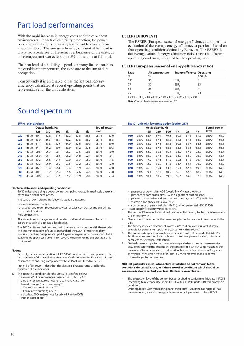
Part load performancesWiththerapidincreaseinenergycostsandthecareaboutenvironmentalimpactsofelectricityproduction,thepowerconsumptionofairconditioningequipmenthasbecomeanimportanttopic.Theenergyefficiencyofaunitatfullloadisrarelyrepresentativeoftheactualperformanceoftheunits,asonaverageaunitworkslessthan5%ofthetimeatfullload.
Theheatloadofabuildingdependsonmanyfactors,suchastheoutsideairtemperature,theexposuretothesunanditsoccupation.
Consequentlyitispreferabletousetheseasonalenergyefficiency,calculatedatseveraloperatingpointsthatarerepresentativefortheunitutilisation.
ESEER (EUROVENT)TheESEER(Europeanseasonalenergyefficiencyratio)permitsevaluationoftheaverageenergyefficiencyatpartload,basedonfouroperatingconditionsdefinedbyEurovent.TheESEERistheaveragevalueofenergyefficiencyratios(EER)atdifferentoperatingconditions,weightedbytheoperatingtime.
ESEER (European seasonal energy efficiency ratio)
Load%
Air temperature °C
Energy efficiency Operating fime, %
100 35 EER1
3
75 30 EER2
33
50 25 EER3
41
25 20 EER4
23
ESEER = EER1 x 3% + EER
2 x 33% + EER
3 x 41% + EER
4 x 23%
Note: Constant leaving water temperature = 7°C
Electrical data notes and operating conditions:• BW10 units have a single power connection point, located immediately upstream
of the main disconnect switch.
• The control box includes the following standard features:
- a main disconnect switch, - the starter and motor protection devices for each compressor and the pumps - the control devices• Field connections:
• All connections to the system and the electrical installations must be in full accordance with all applicable local codes.
• The BW10 units are designed and built to ensure conformance with these codes. The recommendations of European standard EN 60204-1 (machine safety - electrical machine components - part 1: general regulations - corresponds to IEC 60204-1) are specifically taken into account, when designing the electrical unit equipment.
Notes:• Generally the recommendations of IEC 60364 are accepted as compliance with the
requirements of the installation directives. Conformance with EN 60204-1 is the best means of ensuring compliance with the Machines Directive § 1.5.1.
• Annex B of EN 60204-1 describes the electrical characteristics used for the operation of the machines.
1. The operating conditions for the units are specified below: Environment* - Environment as classified in IEC 60364 § 3: - ambient temperature range: +5°C to +40°C, class AA4 - humidity range (non-condensing)*: - 50% relative humidity at 40°C - 90% relative humidity at 20°C - altitude: ≤ 2000 m (see note for table 4.5 in the IOM) - indoor installation*
- presence of water: class AD2 (possibility of water droplets) - presence of hard solids, class 4S2 (no significant dust present) - presence of corrosive and polluting substances, class 4C2 (negligible) - vibration and shock, class AG2, AH2 - competence of personnel, class BA4* (trained personnel - IEC 60364)2. Power supply frequency variation: ± 2 Hz.3. The neutral (N) conductor must not be connected directly to the unit (if necessary
use a transformer).4. Over-current protection of the power supply conductors is not provided with the
unit.5. The factory-installed disconnect switch(es)/circuit breaker(s) is (are) of a type
suitable for power interruption in accordance with EN 60947.6. The units are designed for simplified connection on TN(s) networks (IEC 60364).
For IT networks provide a local earth and consult competent local organisations to complete the electrical installation.
7. Derived currents: If protection by monitoring of derived currents is necessary to ensure the safety of the installation, the control of the cut-out value must take the presence of leak currents into consideration that result from the use of frequency converters in the unit. A value of at least 150 mA is recommended to control differential protection devices.
NOTE: If particular aspects of an actual installation do not conform to the conditions described above, or if there are other conditions which should be considered, always contact your local Danfoss representative.
* The protection level of the control boxes required to conform to this class is IPX1B (according to reference document IEC 60529). All BW10 units fulfil this protection condition.
Units equipped with front casing panel meet class IP23. If the casing panel has been removed, access to energised components is protected to level IPXXB.
BW10 - standard unitOctave bands, Hz Sound power
level 125 250 500 1k 2k 4k020 dB(A) 60.1 52.8 51.6 63.2 60.8 56.5 dB(A) 67.0025 dB(A) 63.9 56.3 55.7 63.2 59.8 58.2 dB(A) 68.5030 dB(A) 61.1 58.8 57.6 64.0 62.6 59.9 dB(A) 69.0035 dB(A) 64.1 59.2 59.0 63.9 61.2 57.8 dB(A) 69.3040 dB(A) 58.6 59.7 58.4 66.7 63.6 58.5 dB(A) 70.0045 dB(A) 56.9 56.1 56.8 66.2 64.8 62.1 dB(A) 70.1050 dB(A) 47.2 59.6 64.6 67.9 65.7 56.3 dB(A) 71.5060 dB(A) 43.2 60.9 65.2 67.5 67.2 56.7 dB(A) 72.0070 dB(A) 46.3 61.4 66.8 67.4 65.9 54.8 dB(A) 72.0080 dB(A) 40.1 61.2 65.4 69.6 67.6 54.8 dB(A) 73.0090 dB(A) 50.6 64.1 63.9 69.2 68.9 58.4 dB(A) 73.4
BW10 - Unit with low-noise option (option 257)Octave bands, Hz Sound power
level 125 250 500 1k 2k 4k020 dB(A) 58.7 57.9 49.8 60.3 57.2 51.2 dB(A) 65.0025 dB(A) 58.2 57.4 55.2 61.6 57.5 54.2 dB(A) 65.8030 dB(A) 58.2 57.4 55.5 60.8 58.7 54.3 dB(A) 65.8035 dB(A) 58.2 57.4 58.5 62.2 58.8 53.8 dB(A) 66.6040 dB(A) 63.9 58.2 56.4 63.6 59.8 53.0 dB(A) 68.4045 dB(A) 58.2 57.4 56.3 64.6 62.5 58.0 dB(A) 68.4050 dB(A) 47.5 57.4 61.0 65.4 61.8 50.7 dB(A) 68.4060 dB(A) 43.2 58.5 61.3 64.7 63.1 50.9 dB(A) 68.6070 dB(A) 46.6 59.4 63.3 65.0 62.2 49.3 dB(A) 69.0080 dB(A) 39.4 58.1 60.9 66.1 62.8 48.2 dB(A) 69.0090 dB(A) 50.4 61.5 59.8 66.2 64.6 52.3 dB(A) 69.9
Sound spectrum
11
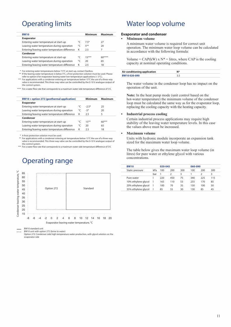
Operating limitsBW10 Minimum MaximumEvaporatorEntering water temperature at start-up °C 7.5* 27Leaving water temperature during operation °C 5** 20Entering/leaving water temperature difference K 2.5 7CondenserEntering water temperature at start-up °C 15*** 60****Leaving water temperature during operation °C 20 65Entering/leaving water temperature difference K 2.5 18
* For entering water temperatures below 7.5°C at start-up, contact Danfoss. ** If the leaving water temperature is below 5°C, a frost protection solution must be used. Please
refer to option 6 for evaporator leaving water low-temperature applications (< 5°C). *** For applications with a condenser entering air temperature below 15°C the use of a three-way
valve is recommended. This three-way valve can be controlled by the 0-10 V analogue output of the control system.
**** For a water flow rate that corresponds to a maximum water-side temperature difference of 5 K.
BW10 + option 272 (geothermal application) Minimum MaximumEvaporatorEntering water temperature at start-up °C -2.5* 25Leaving water temperature during operation °C -5* 20Entering/leaving water temperature difference K 2.5 5CondenserEntering water temperature at start-up °C 15** 60***Leaving water temperature during operation °C 20 65Entering/leaving water temperature difference K 2.5 18
* A frost protection solution must be used. ** For applications with a condenser entering air temperature below 15°C the use of a three-way
valve is recommended. This three-way valve can be controlled by the 0-10 V analogue output of the control system.
*** For a water flow rate that corresponds to a maximum water-side temperature difference of 5 K.
Evaporator leaving water temperature, °C
Con
dens
er le
avin
g w
ater
tem
per
atur
e, °C
Operating range
BW10 standard unit BW10 unit with option 272 (brine to water)
Option 272: Condenser-side high-temperature water production, with glycol solution on the evaporator side
15 20 25 30 35 40 45 50 55 60 65
-8 -6 -4 -2 0 2 4 6 8 10 12 14 16 18 20
StandardOption 272
Evaporator and condenser• Minimumvolume
Aminimumwatervolumeisrequiredforcorrectunitoperation.Theminimumwaterloopvolumecanbecalculatedinaccordancewiththefollowingformula:
Volume=CAP(kW)xN*=litres,whereCAPisthecoolingcapacityatnominaloperatingconditions.
Air conditioning application N*BW10 020-090 3.5
Thewatervolumeinthecondenserloophasnoimpactontheoperationoftheunit.
Note:Intheheatpumpmode(unitcontrolbasedonthehot-watertemperature)theminimumvolumeofthecondenserloopmustbecalculatedthesamewayasfortheevaporatorloop,replacingthecoolingcapacitywiththeheatingcapacity.
• IndustrialprocesscoolingCertainindustrialprocessapplicationsmayrequirehighstabilityoftheleavingwatertemperaturelevels.Inthiscasethevaluesabovemustbeincreased.
• MaximumvolumeUnitswithhydronicmoduleincorporateanexpansiontanksizedforthemaximumwaterloopvolume.
Thetablebelowgivesthemaximumwaterloopvolume(inlitres)forpurewaterorethyleneglycolwithvariousconcentrations.
BW10 020-045 060-090Static pressure kPa 100 200 300 100 200 300
bar 1 2 3 1 2 3Pure water l 220 450 75 340 225 11510% ethylene glycol l 165 110 53 255 170 8520% ethylene glycol l 100 70 35 150 100 5035% ethylene glycol l 85 55 30 130 85 45
Water loop volume
12
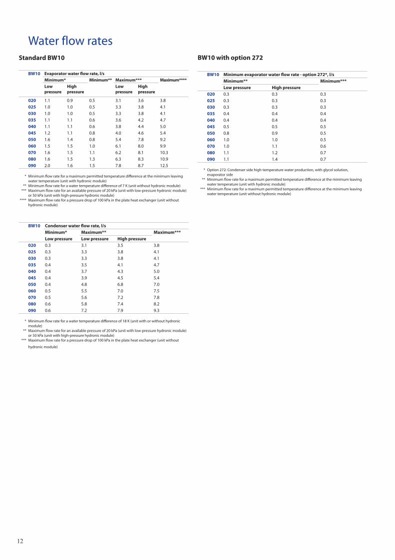
Water flow ratesStandard BW10
BW10 Evaporator water flow rate, l/sMinimum* Minimum** Maximum*** Maximum****Low pressure
High pressure
Low pressure
High pressure
020 1.1 0.9 0.5 3.1 3.6 3.8025 1.0 1.0 0.5 3.3 3.8 4.1030 1.0 1.0 0.5 3.3 3.8 4.1035 1.1 1.1 0.6 3.6 4.2 4.7040 1.1 1.1 0.6 3.8 4.4 5.0045 1.2 1.1 0.8 4.0 4.6 5.4050 1.6 1.4 0.8 5.4 7.8 9.2060 1.5 1.5 1.0 6.1 8.0 9.9070 1.6 1.5 1.1 6.2 8.1 10.3080 1.6 1.5 1.3 6.3 8.3 10.9090 2.0 1.6 1.5 7.8 8.7 12.5
* Minimum flow rate for a maximum permitted temperature difference at the minimum leaving water temperature (unit with hydronic module)
** Minimum flow rate for a water temperature difference of 7 K (unit without hydronic module) *** Maximum flow rate for an available pressure of 20 kPa (unit with low-pressure hydronic module)
or 50 kPa (unit with high-pressure hydronic module) **** Maximum flow rate for a pressure drop of 100 kPa in the plate heat exchanger (unit without
hydronic module)
BW10 Condenser water flow rate, l/sMinimum* Maximum** Maximum***Low pressure Low pressure High pressure
020 0.3 3.1 3.5 3.8025 0.3 3.3 3.8 4.1030 0.3 3.3 3.8 4.1035 0.4 3.5 4.1 4.7040 0.4 3.7 4.3 5.0045 0.4 3.9 4.5 5.4050 0.4 4.8 6.8 7.0060 0.5 5.5 7.0 7.5070 0.5 5.6 7.2 7.8080 0.6 5.8 7.4 8.2090 0.6 7.2 7.9 9.3
* Minimum flow rate for a water temperature difference of 18 K (unit with or without hydronic module)
** Maximum flow rate for an available pressure of 20 kPa (unit with low-pressure hydronic module) or 50 kPa (unit with high-pressure hydronic module)
*** Maximum flow rate for a pressure drop of 100 kPa in the plate heat exchanger (unit without
hydronic module)
BW10 with option 272
BW10 Minimum evaporator water flow rate - option 272*, l/sMinimum** Minimum***Low pressure High pressure
020 0.3 0.3 0.3025 0.3 0.3 0.3030 0.3 0.3 0.3035 0.4 0.4 0.4040 0.4 0.4 0.4045 0.5 0.5 0.5050 0.8 0.9 0.5060 1.0 1.0 0.5070 1.0 1.1 0.6080 1.1 1.2 0.7090 1.1 1.4 0.7
* Option 272: Condenser side high-temperature water production, with glycol solution, evaporator side
** Minimum flow rate for a maximum permitted temperature difference at the minimum leaving water temperature (unit with hydronic module)
*** Minimum flow rate for a maximum permitted temperature difference at the minimum leaving water temperature (unit without hydronic module)
13
0102030405060708090
100110120130140150
0.0 0.5 1.0 1.5 2.0 2.5 3.0 3.5 4.0 4.5 5.0 5.5 6.0 6.5 7.0 7.5 8.0
0.0 0.5 1.0 1.5 2.0 2.5 3.0 3.5 4.0 4.5 5.0 5.5 6.0 6.5 7.0 7.5 8.0
-100
102030405060708090
100110120130140150160170180
0 1 2 3 4 5 6 7 8 9 10 11 12 13 14 15 16
0102030405060708090
100110120130140150
0102030405060708090
100110120130140150160170180
0 1 2 3 4 5 6 7 8 9 10 11 12 13
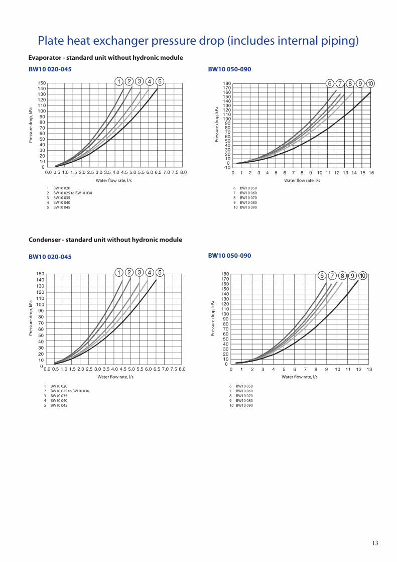
Plate heat exchanger pressure drop (includes internal piping)Evaporator - standard unit without hydronic module
BW10 020-045 BW10 050-090
1 BW10 020 2 BW10 025 to BW10 0303 BW10 0354 BW10 0405 BW10 045
6 BW10 050 7 BW10 0608 BW10 0709 BW10 08010 BW10 090
Condenser - standard unit without hydronic module
BW10 020-045
1 BW10 020 2 BW10 025 to BW10 0303 BW10 0354 BW10 0405 BW10 045
6 BW10 050 7 BW10 0608 BW10 0709 BW10 08010 BW10 090
BW10 050-090
Pres
sure
dro
p, k
Pa
Water flow rate, l/s
Pres
sure
dro
p, k
Pa
Water flow rate, l/s
Pres
sure
dro
p, k
Pa
Water flow rate, l/s
Pres
sure
dro
p, k
Pa
Water flow rate, l/s
14
50 60 70 80 90
100 110 120 130 140 150 160
0.0 0.5 1.0 1.5 2.0 2.5 3.0 3.5 4.0 4.5 5.0 50
70
90
110
130
150
170
190
210
0 1 2 3 4 5 6 7 8 9
50 60 70 80 90
100 110 120 130 140 150 160
0.0 0.5 1.0 1.5 2.0 2.5 3.0 3.5 4.0 4.5 50
70
90
110
130
150
170
190
210
0 1 2 3 4 5 6 7 8
Condenser
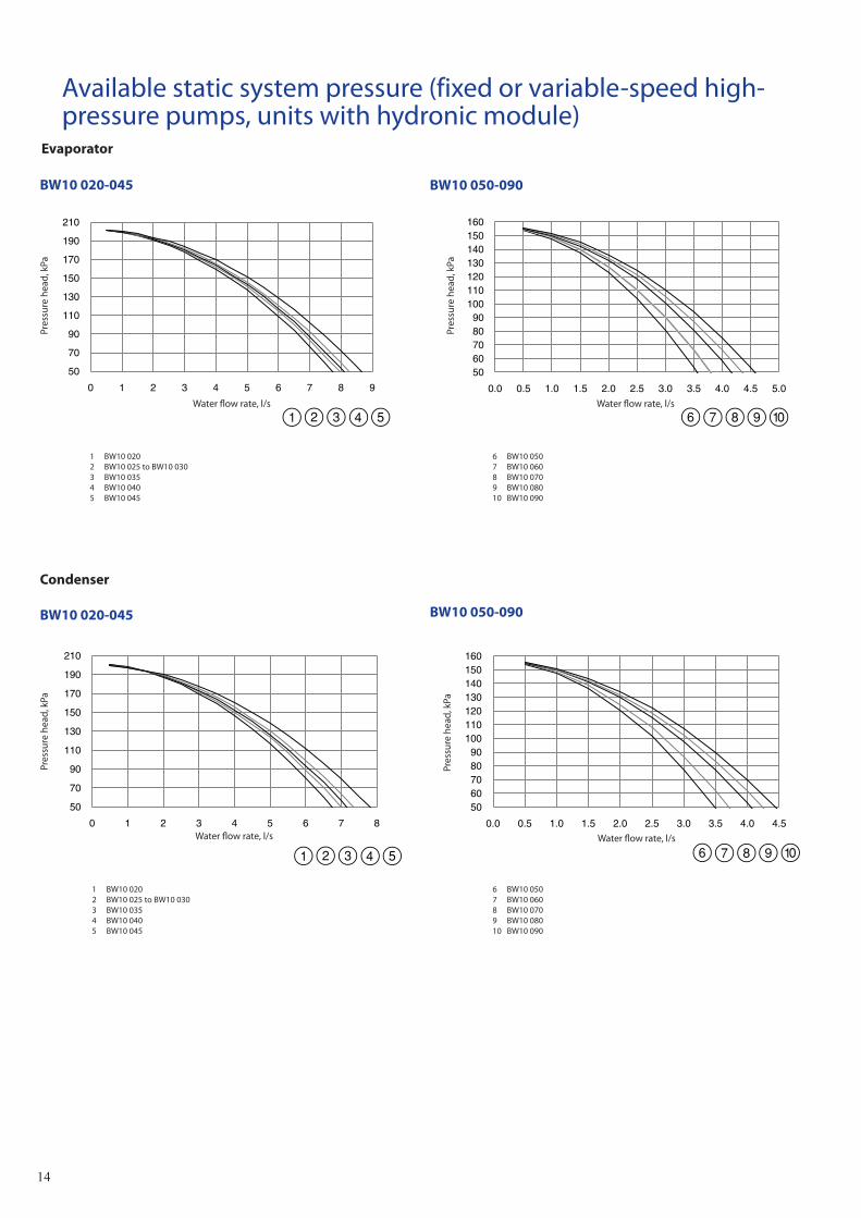
Available static system pressure (fixed or variable-speed high-pressure pumps, units with hydronic module)
Evaporator
1 BW10 020 2 BW10 025 to BW10 0303 BW10 0354 BW10 0405 BW10 045
6 BW10 050 7 BW10 0608 BW10 0709 BW10 08010 BW10 090
1 BW10 020 2 BW10 025 to BW10 0303 BW10 0354 BW10 0405 BW10 045
6 BW10 050 7 BW10 0608 BW10 0709 BW10 08010 BW10 090
BW10 020-045 BW10 050-090
BW10 020-045 BW10 050-090
Pres
sure
hea
d, k
Pa
Water flow rate, l/s
Pres
sure
hea
d, k
Pa
Water flow rate, l/s
Pres
sure
hea
d, k
Pa
Water flow rate, l/s
Pres
sure
hea
d, k
Pa
Water flow rate, l/s
15
20 30 40 50 60 70 80 90
100 110
0.0 0.5 1.0 1.5 2.0 2.5 3.0 3.5 4.0 20 30 40 50 60 70 80 90
100 110 120 130 140 150 160
0 1 2 3 4 5 6 7 8
20 30 40 50 60 70 80 90
100 110
0.0 0.5 1.0 1.5 2.0 2.,5 3.0 3.5 4.0 20 30 40 50 60 70 80 90
100 110 120 130 140 150 160
0 1 2 3 4 5 6 7 8
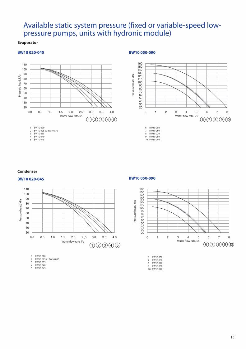
Available static system pressure (fixed or variable-speed low-pressure pumps, units with hydronic module)
Evaporator
1 BW10 0202 BW10 025 to BW10 0303 BW10 0354 BW10 0405 BW10 045
6 BW10 050 7 BW10 0608 BW10 0709 BW10 08010 BW10 090
1 BW10 020 2 BW10 025 to BW10 0303 BW10 0354 BW10 0405 BW10 045
6 BW10 050 7 BW10 0608 BW10 0709 BW10 08010 BW10 090
BW10 020-045 BW10 050-090
Pres
sure
hea
d, k
Pa
Water flow rate, l/s
Pres
sure
hea
d, k
Pa
Water flow rate, l/s
Pres
sure
hea
d, k
Pa
Water flow rate, l/s Water flow rate, l/s
Pres
sure
hea
d, k
Pa
Condenser
BW10 020-045 BW10 050-090
16
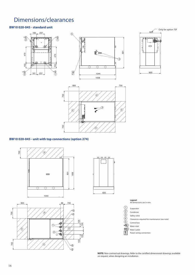
Dimensions/clearancesBW10 020-045 - standard unit
Legend: All dimensions are in mm.
Evaporator
Condenser
Safety valve
Clearances required for maintenance (see note)
Control box
Water inlet
Water outlet
Power wiring connection
161 237
153
470
160 237
153
470
1058
900
700
700
1044 600
625
901
700
2
2 1
1
4
4
4
4
5
3
3
BW10 020-045 - unit with top connections (option 274)
901
938
86
105
104
105
143
1044600
700
900
700
700
700
2
1
4
4
4
4
4
Only for option 70F
NOTE: Non-contractual drawings. Refer to the certified dimensional drawings available on request, when designing an installation.
17
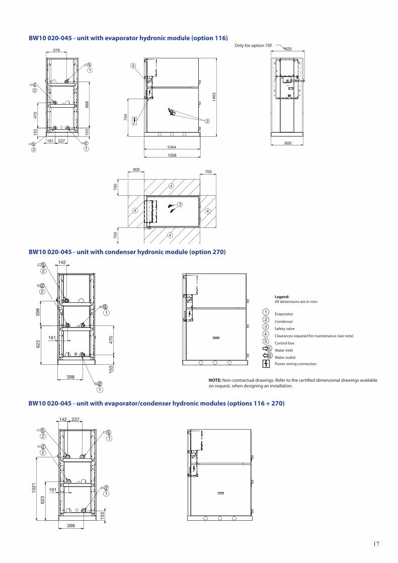
BW10 020-045 - unit with evaporator hydronic module (option 116)
BW10 020-045 - unit with condenser hydronic module (option 270)
BW10 020-045 - unit with evaporator/condenser hydronic modules (options 116 + 270)
700
900
700
153
153
161 237
470
868
1044
1058
1463
704
600
625
700
379
4
4
4
4
5
2
2 1
1
3
3
398
153
161
623
1021
142 237
2
2
1
1
398
153
470
398
161
142
623
2
2
1
1
Only for option 70F
Legend: All dimensions are in mm.
Evaporator
Condenser
Safety valve
Clearances required for maintenance (see note)
Control box
Water inlet
Water outlet
Power wiring connection
NOTE: Non-contractual drawings. Refer to the certified dimensional drawings available on request, when designing an installation.
18
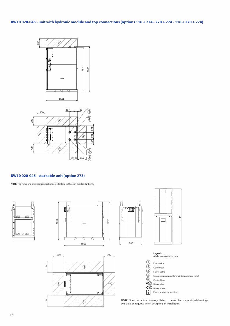
BW10 020-045 - unit with hydronic module and top connections (options 116 + 274 - 270 + 274 - 116 + 270 + 274)
900
700
700
143
86
237
221
86167
167
1044
1463
1500
700
700
2
2
1
1
4
4
4
4
4
BW10 020-045 - stackable unit (option 273)
NOTE: The water and electrical connections are identical to those of the standard unit.
1014
1014
1058 600
1841
900
700
700
700
4
4
4
4
Legend: All dimensions are in mm.
Evaporator
Condenser
Safety valve
Clearances required for maintenance (see note)
Control box
Water inlet
Water outlet
Power wiring connection
NOTE: Non-contractual drawings. Refer to the certified dimensional drawings available on request, when designing an installation.
19
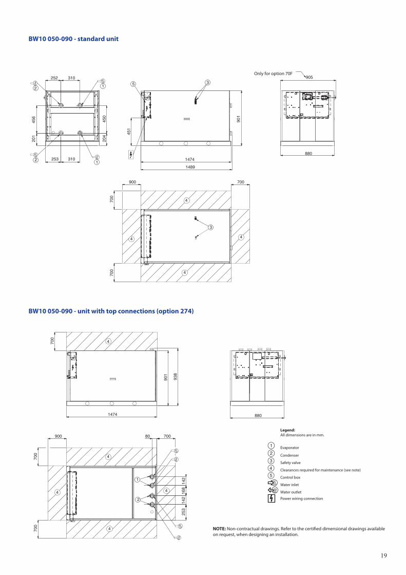
BW10 050-090 - standard unit
BW10 050-090 - unit with top connections (option 274)
900
700
700
253 310
201
204
456
450
252 310
451
1474
1489
901
905
880
700
2
2 1
1
4
4
4
4
5 3
3
700
900
700
253
142
168
142
80
1474
901
938
880
700
700
2
1
4
4
4
4
4
Only for option 70F
Legend: All dimensions are in mm.
Evaporator
Condenser
Safety valve
Clearances required for maintenance (see note)
Control box
Water inlet
Water outlet
Power wiring connection
NOTE: Non-contractual drawings. Refer to the certified dimensional drawings available on request, when designing an installation.
20
900
700
700
657
1021
307
252
558
204
704
1474
1488
1463
905
700
880253
2
2 1
1
4
4
4
4
5
3
3
657
1021
559
252
277
204
2
2
1
1
657
1021
559
252
277
204
282
2
2
1
1
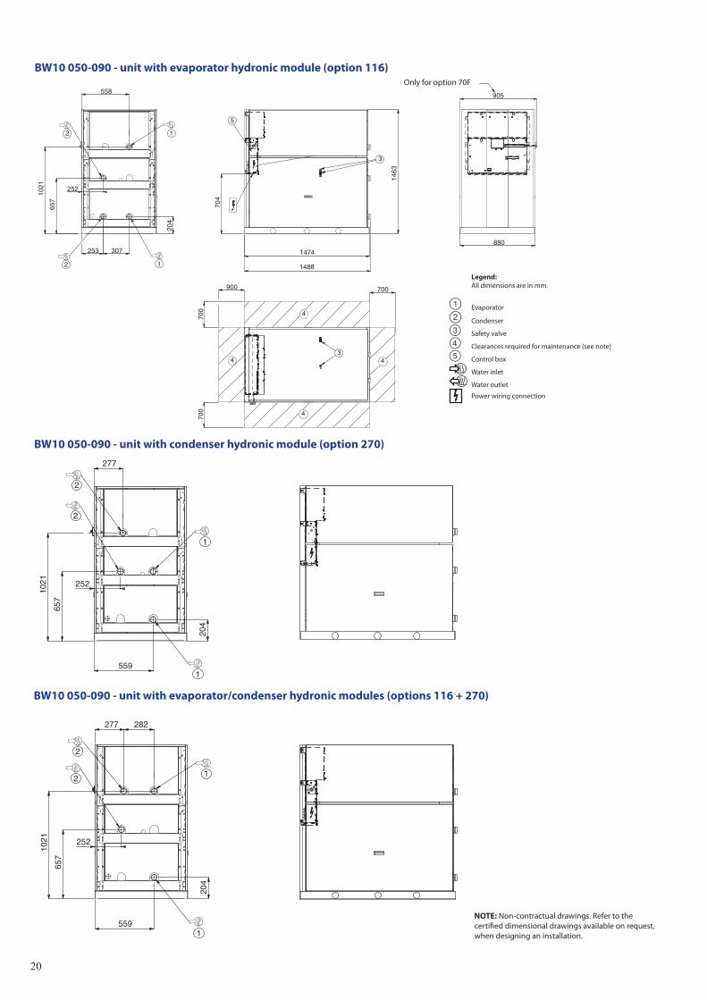
BW10 050-090 - unit with evaporator hydronic module (option 116)
BW10 050-090 - unit with condenser hydronic module (option 270)
BW10 050-090 - unit with evaporator/condenser hydronic modules (options 116 + 270)
Only for option 70F
Legend: All dimensions are in mm.
Evaporator
Condenser
Safety valve
Clearances required for maintenance (see note)
Control box
Water inlet
Water outlet
Power wiring connection
NOTE: Non-contractual drawings. Refer to the certified dimensional drawings available on request, when designing an installation.
21
900
700
700
700
1463
1500
1474
80172
278
282
80172
700
2
2
1
1
4
4
4
4
4
1841
1014
1489
1014
700
900
700
880
700
4
4
4
4
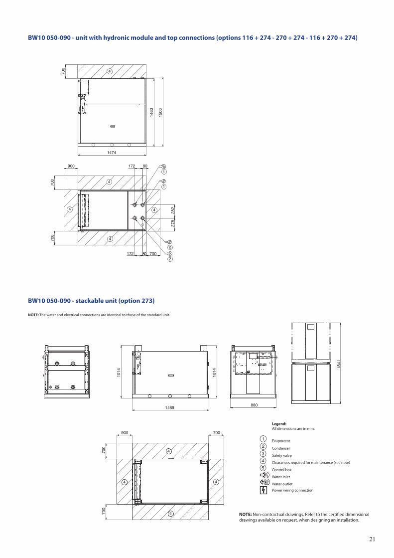
BW10 050-090 - unit with hydronic module and top connections (options 116 + 274 - 270 + 274 - 116 + 270 + 274)
BW10 050-090 - stackable unit (option 273)
NOTE: The water and electrical connections are identical to those of the standard unit.
Legend: All dimensions are in mm.
Evaporator
Condenser
Safety valve
Clearances required for maintenance (see note)
Control box
Water inlet
Water outlet
Power wiring connection
NOTE: Non-contractual drawings. Refer to the certified dimensional drawings available on request, when designing an installation.
22
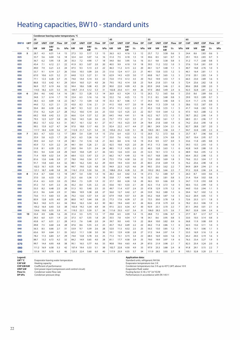
Legend: LWT °C Evaporator leaving water temperature CAP kW Heating capacity COP kW/kW Coefficient of performance UNIT kW Unit power input (compressors and control circuit) Flow l/s Condenser water flow rate DP kPa Condenser pressure drop
Application data: Standard units, refrigerant: R410A Evaporator temperature rise: 3 K Condenser temperature rise: 5 K up to 45°C LWT, above 10 K Evaporator fluid: water Fouling factor: 0.18 x 10⁻⁴ (m2 K)/W Performances in accordance with EN 14511
Heating capacities, BW10 - standard unitsCondenser leaving water temperature, °C
25 35 45 55 65
BW10 LWT CAP UNIT COP Flow DP CAP UNIT COP Flow DP CAP UNIT COP Flow DP CAP UNIT COP Flow DP CAP UNIT COP Flow DP
°C kW kWkW/kW
l/s kPa kW kWkW/kW
l/s kPa kW kWkW/kW
l/s kPa kW kWkW/kW
l/s kPa kW kWkW/kW
l/s kPa
020 5 28.7 4.5 6.31 1.4 15 27.3 5.3 5.17 1.3 13 26.3 6.3 4.16 1.3 12 25.7 7.2 3.58 0.6 5 24.4 8.6 2.83 0.6 5
025 33.7 5.6 6.04 1.6 18 32.4 6.4 5.07 1.6 16 31.4 7.5 4.18 1.5 14 30.6 8.5 3.61 0.7 5 29.1 10.3 2.83 0.7 5
030 36.7 6.2 5.95 1.8 20 35.3 7.2 4.90 1.7 18 34.0 8.6 3.95 1.6 16 33.1 9.8 3.38 0.8 5 31.2 11.7 2.68 0.8 5
035 43.4 7.1 6.12 2.1 22 41.9 8.3 5.07 2.0 20 40.5 9.9 4.10 1.9 18 39.5 11.2 3.52 1.0 5 37.6 13.4 2.81 0.9 5
040 49.0 7.9 6.21 2.3 24 47.5 9.3 5.13 2.3 22 46.3 11.2 4.15 2.2 20 44.1 12.7 3.48 1.1 5 40.7 14.8 2.76 1.0 5
045 55.7 9.1 6.14 2.7 26 53.6 10.5 5.09 2.6 23 51.6 12.4 4.17 2.5 21 49.1 13.8 3.55 1.2 5 46.1 16.4 2.81 1.1 5
050 67.0 10.6 6.31 3.2 21 64.8 12.3 5.27 3.1 19 62.9 14.5 4.33 3.0 17 60.8 16.7 3.65 1.5 5 57.0 20.1 2.83 1.4 5
060 77.1 12.3 6.28 3.7 25 74.0 14.4 5.14 3.5 22 72.0 17.5 4.12 3.5 20 70.2 19.9 3.53 1.7 5 66.5 23.0 2.89 1.6 5
070 86.8 13.5 6.42 4.1 29 83.4 16.0 5.21 4.0 26 79.5 19.2 4.14 3.8 23 76.4 21.8 3.51 1.8 5 72.4 25.6 2.82 1.8 5
080 96.9 15.7 6.19 4.6 32 94.4 18.6 5.08 4.5 29 90.0 22.0 4.09 4.3 26 85.9 24.8 3.46 2.1 6 80.6 28.8 2.80 2.0 5
090 114.5 18.2 6.31 5.5 35 109.7 21.4 5.12 5.3 31 102.8 25.0 4.11 4.9 26 97.9 28.0 3.49 2.4 6 92.3 32.8 2.81 2.2 5
020 6 29.6 4.6 6.42 1.4 16 28.1 5.3 5.28 1.3 14 26.9 6.3 4.24 1.3 13 26.3 7.2 3.65 0.6 5 25.0 8.6 2.89 0.6 5
025 34.8 5.7 6.14 1.7 19 33.4 6.5 5.16 1.6 16 32.2 7.6 4.25 1.5 15 31.3 8.5 3.68 0.8 5 29.9 10.3 2.89 0.7 5
030 38.3 6.3 6.09 1.8 22 36.7 7.3 5.04 1.8 19 35.3 8.7 4.06 1.7 17 34.3 9.8 3.48 0.8 5 32.4 11.7 2.76 0.8 5
035 44.6 7.2 6.21 2.1 23 43.0 8.3 5.16 2.1 21 41.5 10.0 4.17 2.0 19 40.4 11.3 3.59 1.0 5 38.6 13.5 2.87 0.9 5
040 50.4 8.0 6.30 2.4 26 48.7 9.3 5.22 2.3 23 47.4 11.2 4.22 2.3 21 45.3 12.8 3.55 1.1 5 41.7 14.8 2.82 1.0 5
045 57.6 9.2 6.24 2.7 28 55.2 10.6 5.19 2.6 25 53.0 12.5 4.25 2.5 22 50.7 13.9 3.64 1.2 6 47.5 16.5 2.88 1.2 5
050 69.2 10.8 6.42 3.3 23 66.6 12.4 5.37 3.2 20 64.5 14.6 4.41 3.1 18 62.2 16.7 3.72 1.5 5 58.7 20.2 2.90 1.4 5
060 79.3 12.5 6.37 3.8 26 76.0 14.5 5.24 3.6 23 73.7 17.5 4.21 3.5 21 72.1 20.0 3.61 1.7 5 68.5 23.1 2.96 1.7 5
070 89.2 13.7 6.52 4.3 31 85.7 16.1 5.32 4.1 27 81.7 19.3 4.23 3.9 24 78.4 21.8 3.60 1.9 6 74.2 25.6 2.90 1.8 5
080 99.5 15.9 6.27 4.7 34 97.0 18.8 5.17 4.6 31 92.4 22.2 4.17 4.4 27 88.1 24.9 3.54 2.1 6 82.7 28.8 2.87 2.0 5
090 117.7 18.4 6.39 5.6 37 112.9 21.7 5.21 5.4 33 105.6 25.2 4.20 5.1 28 100.5 28.1 3.58 2.4 7 94.7 32.8 2.89 2.3 6
020 7 30.5 4.7 6.53 1.5 17 28.9 5.4 5.39 1.4 15 27.6 6.4 4.33 1.3 13 26.9 7.2 3.72 0.6 5 25.7 8.7 2.96 0.6 5
025 35.9 5.8 6.23 1.7 20 34.3 6.5 5.26 1.6 17 33.0 7.6 4.32 1.6 15 32.0 8.5 3.74 0.8 5 30.7 10.4 2.95 0.7 5
030 39.9 6.4 6.21 1.9 24 38.1 7.4 5.16 1.8 21 36.5 8.8 4.16 1.8 19 35.4 9.9 3.57 0.9 5 33.6 11.8 2.85 0.8 5
035 45.9 7.3 6.31 2.2 24 44.1 8.4 5.26 2.1 22 42.5 10.0 4.25 2.0 20 41.3 11.3 3.66 1.0 5 39.5 13.5 2.93 1.0 5
040 51.8 8.1 6.39 2.5 27 50.0 9.4 5.31 2.4 24 48.5 11.3 4.29 2.3 22 46.5 12.8 3.63 1.1 6 42.8 14.9 2.88 1.0 5
045 59.5 9.4 6.34 2.8 29 56.9 10.8 5.29 2.7 26 54.5 12.6 4.33 2.6 23 52.3 14.1 3.72 1.3 6 48.9 16.6 2.95 1.2 5
050 71.4 10.9 6.52 3.4 24 68.4 12.5 5.47 3.3 21 66.2 14.7 4.49 3.2 19 63.7 16.8 3.80 1.5 5 60.4 20.3 2.98 1.5 5
060 81.6 12.6 6.46 3.9 27 78.0 14.6 5.34 3.7 24 75.5 17.6 4.30 3.6 22 73.9 20.0 3.69 1.8 5 70.6 23.2 3.04 1.7 5
070 91.7 13.8 6.63 4.4 32 88.1 16.2 5.43 4.2 29 83.9 19.4 4.33 4.0 25 80.5 21.8 3.69 1.9 6 76.2 25.6 2.98 1.8 5
080 102.3 16.1 6.35 4.9 36 99.7 19.0 5.25 4.8 33 94.9 22.3 4.25 4.6 29 90.5 25.0 3.62 2.2 7 84.9 28.9 2.94 2.1 6
090 121.1 18.7 6.48 5.8 39 116.1 21.9 5.30 5.6 35 108.6 25.4 4.28 5.2 29 103.2 28.2 3.66 2.5 7 97.2 32.8 2.96 2.4 6
020 8 31.4 4.7 6.64 1.5 18 29.7 5.4 5.50 1.4 16 28.3 6.4 4.42 1.4 14 27.5 7.2 3.80 0.7 5 26.3 8.7 3.03 0.6 5
025 37.0 5.8 6.33 1.8 21 35.3 6.6 5.36 1.7 18 33.8 7.7 4.40 1.6 16 32.7 8.6 3.81 0.8 5 31.4 10.4 3.02 0.8 5
030 41.4 6.5 6.33 2.0 25 39.4 7.5 5.29 1.9 22 37.7 8.8 4.26 1.8 20 36.5 9.9 3.66 0.9 5 34.7 11.9 2.93 0.8 5
035 47.2 7.4 6.41 2.3 26 45.2 8.4 5.35 2.2 23 43.6 10.1 4.33 2.1 20 42.3 11.4 3.72 1.0 5 40.5 13.5 2.99 1.0 5
040 53.3 8.2 6.48 2.5 28 51.3 9.5 5.40 2.5 25 49.7 11.4 4.37 2.4 23 47.8 12.9 3.70 1.2 6 44.0 15.0 2.94 1.1 5
045 61.5 9.6 6.44 2.9 31 58.6 10.9 5.38 2.8 27 56.0 12.7 4.42 2.7 24 53.9 14.2 3.80 1.3 6 50.4 16.7 3.02 1.2 5
050 73.6 11.1 6.63 3.5 26 70.2 12.6 5.57 3.4 22 67.9 14.8 4.57 3.3 20 65.2 16.8 3.87 1.6 5 62.2 20.4 3.05 1.5 5
060 83.9 12.8 6.55 4.0 29 80.0 14.7 5.44 3.8 25 77.3 17.6 4.39 3.7 23 75.5 20.0 3.78 1.8 5 72.6 23.3 3.11 1.8 5
070 94.3 14.0 6.73 4.5 34 90.4 16.3 5.54 4.3 30 86.1 19.4 4.43 4.1 26 82.6 21.8 3.79 2.0 6 78.2 25.5 3.06 1.9 5
080 105.2 16.4 6.43 5.0 38 102.4 19.2 5.34 4.9 34 97.5 22.5 4.34 4.7 30 92.9 25.1 3.70 2.2 7 87.1 29.0 3.01 2.1 6
090 124.6 19.0 6.55 5.9 41 119.3 22.1 5.39 5.7 36 111.6 25.5 4.37 5.4 31 106.0 28.3 3.75 2.6 7 99.7 32.8 3.04 2.4 6
020 10 33.4 4.9 6.86 1.6 20 31.4 5.5 5.73 1.5 17 29.8 6.5 4.59 1.4 15 28.8 7.3 3.96 0.7 5 27.7 8.7 3.17 0.7 5
025 39.3 6.0 6.51 1.9 23 37.3 6.7 5.55 1.8 20 35.5 7.8 4.54 1.7 18 34.1 8.6 3.95 0.8 5 33.0 10.5 3.14 0.8 5
030 43.8 6.7 6.51 2.1 28 41.5 7.6 5.48 2.0 24 39.7 9.0 4.43 1.9 22 38.4 10.0 3.82 0.9 6 36.8 11.9 3.08 0.9 5
035 49.8 7.5 6.60 2.4 28 47.6 8.6 5.55 2.3 25 45.7 10.2 4.49 2.2 22 44.2 11.4 3.86 1.1 6 42.5 13.6 3.11 1.0 5
040 56.3 8.5 6.66 2.7 31 53.9 9.7 5.59 2.6 28 52.0 11.5 4.52 2.5 25 50.3 13.0 3.85 1.2 7 46.3 15.1 3.06 1.1 5
045 65.6 9.9 6.64 3.1 35 62.2 11.1 5.58 3.0 30 59.1 12.9 4.58 2.8 27 57.2 14.4 3.97 1.4 7 53.3 16.9 3.16 1.3 6
050 78.2 11.5 6.83 3.7 29 74.0 12.8 5.78 3.5 25 71.3 15.1 4.73 3.4 22 68.3 16.9 4.03 1.6 5 65.2 20.5 3.19 1.6 5
060 88.7 13.2 6.72 4.2 32 84.2 14.9 5.65 4.0 28 81.1 17.7 4.58 3.9 25 79.0 19.9 3.97 1.9 6 76.3 23.4 3.27 1.9 5
070 99.7 14.4 6.93 4.8 38 95.1 16.5 5.77 4.6 33 90.8 19.6 4.63 4.4 29 87.0 21.9 3.98 2.1 7 82.3 25.4 3.24 2.0 6
080 111.2 16.9 6.58 5.3 42 107.4 19.4 5.53 5.1 38 102.7 22.8 4.50 4.9 33 97.9 25.3 3.88 2.4 8 91.8 29.1 3.15 2.2 7
090 131.8 19.7 6.70 6.3 46 125.3 22.4 5.60 6.0 40 117.9 25.9 4.55 5.7 34 111.9 28.5 3.93 2.7 8 105.1 32.8 3.20 2.5 7
23
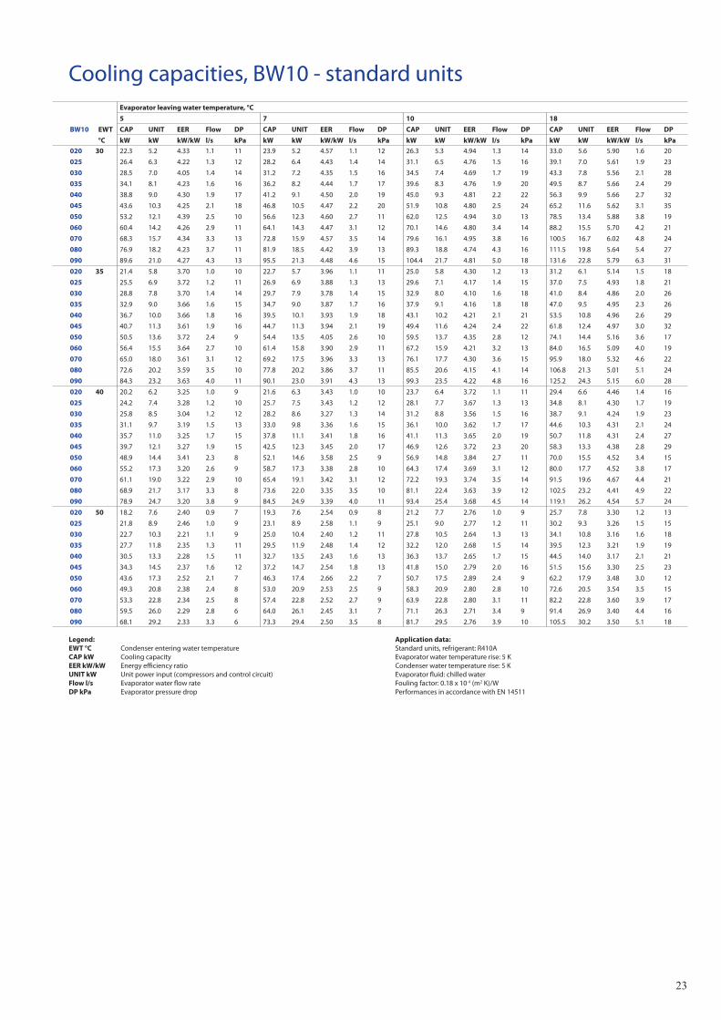
Cooling capacities, BW10 - standard units
Legend: EWT °C Condenser entering water temperature CAP kW Cooling capacity EER kW/kW Energy efficiency ratio UNIT kW Unit power input (compressors and control circuit) Flow l/s Evaporator water flow rate DP kPa Evaporator pressure drop
Application data: Standard units, refrigerant: R410A Evaporator water temperature rise: 5 K Condenser water temperature rise: 5 K Evaporator fluid: chilled water Fouling factor: 0.18 x 10⁻⁴ (m2 K)/W Performances in accordance with EN 14511
Evaporator leaving water temperature, °C
5 7 10 18
BW10 EWT CAP UNIT EER Flow DP CAP UNIT EER Flow DP CAP UNIT EER Flow DP CAP UNIT EER Flow DP
°C kW kW kW/kW l/s kPa kW kW kW/kW l/s kPa kW kW kW/kW l/s kPa kW kW kW/kW l/s kPa
020 30 22.3 5.2 4.33 1.1 11 23.9 5.2 4.57 1.1 12 26.3 5.3 4.94 1.3 14 33.0 5.6 5.90 1.6 20
025 26.4 6.3 4.22 1.3 12 28.2 6.4 4.43 1.4 14 31.1 6.5 4.76 1.5 16 39.1 7.0 5.61 1.9 23
030 28.5 7.0 4.05 1.4 14 31.2 7.2 4.35 1.5 16 34.5 7.4 4.69 1.7 19 43.3 7.8 5.56 2.1 28
035 34.1 8.1 4.23 1.6 16 36.2 8.2 4.44 1.7 17 39.6 8.3 4.76 1.9 20 49.5 8.7 5.66 2.4 29
040 38.8 9.0 4.30 1.9 17 41.2 9.1 4.50 2.0 19 45.0 9.3 4.81 2.2 22 56.3 9.9 5.66 2.7 32
045 43.6 10.3 4.25 2.1 18 46.8 10.5 4.47 2.2 20 51.9 10.8 4.80 2.5 24 65.2 11.6 5.62 3.1 35
050 53.2 12.1 4.39 2.5 10 56.6 12.3 4.60 2.7 11 62.0 12.5 4.94 3.0 13 78.5 13.4 5.88 3.8 19
060 60.4 14.2 4.26 2.9 11 64.1 14.3 4.47 3.1 12 70.1 14.6 4.80 3.4 14 88.2 15.5 5.70 4.2 21
070 68.3 15.7 4.34 3.3 13 72.8 15.9 4.57 3.5 14 79.6 16.1 4.95 3.8 16 100.5 16.7 6.02 4.8 24
080 76.9 18.2 4.23 3.7 11 81.9 18.5 4.42 3.9 13 89.3 18.8 4.74 4.3 16 111.5 19.8 5.64 5.4 27
090 89.6 21.0 4.27 4.3 13 95.5 21.3 4.48 4.6 15 104.4 21.7 4.81 5.0 18 131.6 22.8 5.79 6.3 31
020 35 21.4 5.8 3.70 1.0 10 22.7 5.7 3.96 1.1 11 25.0 5.8 4.30 1.2 13 31.2 6.1 5.14 1.5 18
025 25.5 6.9 3.72 1.2 11 26.9 6.9 3.88 1.3 13 29.6 7.1 4.17 1.4 15 37.0 7.5 4.93 1.8 21
030 28.8 7.8 3.70 1.4 14 29.7 7.9 3.78 1.4 15 32.9 8.0 4.10 1.6 18 41.0 8.4 4.86 2.0 26
035 32.9 9.0 3.66 1.6 15 34.7 9.0 3.87 1.7 16 37.9 9.1 4.16 1.8 18 47.0 9.5 4.95 2.3 26
040 36.7 10.0 3.66 1.8 16 39.5 10.1 3.93 1.9 18 43.1 10.2 4.21 2.1 21 53.5 10.8 4.96 2.6 29
045 40.7 11.3 3.61 1.9 16 44.7 11.3 3.94 2.1 19 49.4 11.6 4.24 2.4 22 61.8 12.4 4.97 3.0 32
050 50.5 13.6 3.72 2.4 9 54.4 13.5 4.05 2.6 10 59.5 13.7 4.35 2.8 12 74.1 14.4 5.16 3.6 17
060 56.4 15.5 3.64 2.7 10 61.4 15.8 3.90 2.9 11 67.2 15.9 4.21 3.2 13 84.0 16.5 5.09 4.0 19
070 65.0 18.0 3.61 3.1 12 69.2 17.5 3.96 3.3 13 76.1 17.7 4.30 3.6 15 95.9 18.0 5.32 4.6 22
080 72.6 20.2 3.59 3.5 10 77.8 20.2 3.86 3.7 11 85.5 20.6 4.15 4.1 14 106.8 21.3 5.01 5.1 24
090 84.3 23.2 3.63 4.0 11 90.1 23.0 3.91 4.3 13 99.3 23.5 4.22 4.8 16 125.2 24.3 5.15 6.0 28
020 40 20.2 6.2 3.25 1.0 9 21.6 6.3 3.43 1.0 10 23.7 6.4 3.72 1.1 11 29.4 6.6 4.46 1.4 16
025 24.2 7.4 3.28 1.2 10 25.7 7.5 3.43 1.2 12 28.1 7.7 3.67 1.3 13 34.8 8.1 4.30 1.7 19
030 25.8 8.5 3.04 1.2 12 28.2 8.6 3.27 1.3 14 31.2 8.8 3.56 1.5 16 38.7 9.1 4.24 1.9 23
035 31.1 9.7 3.19 1.5 13 33.0 9.8 3.36 1.6 15 36.1 10.0 3.62 1.7 17 44.6 10.3 4.31 2.1 24
040 35.7 11.0 3.25 1.7 15 37.8 11.1 3.41 1.8 16 41.1 11.3 3.65 2.0 19 50.7 11.8 4.31 2.4 27
045 39.7 12.1 3.27 1.9 15 42.5 12.3 3.45 2.0 17 46.9 12.6 3.72 2.3 20 58.3 13.3 4.38 2.8 29
050 48.9 14.4 3.41 2.3 8 52.1 14.6 3.58 2.5 9 56.9 14.8 3.84 2.7 11 70.0 15.5 4.52 3.4 15
060 55.2 17.3 3.20 2.6 9 58.7 17.3 3.38 2.8 10 64.3 17.4 3.69 3.1 12 80.0 17.7 4.52 3.8 17
070 61.1 19.0 3.22 2.9 10 65.4 19.1 3.42 3.1 12 72.2 19.3 3.74 3.5 14 91.5 19.6 4.67 4.4 21
080 68.9 21.7 3.17 3.3 8 73.6 22.0 3.35 3.5 10 81.1 22.4 3.63 3.9 12 102.5 23.2 4.41 4.9 22
090 78.9 24.7 3.20 3.8 9 84.5 24.9 3.39 4.0 11 93.4 25.4 3.68 4.5 14 119.1 26.2 4.54 5.7 24
020 50 18.2 7.6 2.40 0.9 7 19.3 7.6 2.54 0.9 8 21.2 7.7 2.76 1.0 9 25.7 7.8 3.30 1.2 13
025 21.8 8.9 2.46 1.0 9 23.1 8.9 2.58 1.1 9 25.1 9.0 2.77 1.2 11 30.2 9.3 3.26 1.5 15
030 22.7 10.3 2.21 1.1 9 25.0 10.4 2.40 1.2 11 27.8 10.5 2.64 1.3 13 34.1 10.8 3.16 1.6 18
035 27.7 11.8 2.35 1.3 11 29.5 11.9 2.48 1.4 12 32.2 12.0 2.68 1.5 14 39.5 12.3 3.21 1.9 19
040 30.5 13.3 2.28 1.5 11 32.7 13.5 2.43 1.6 13 36.3 13.7 2.65 1.7 15 44.5 14.0 3.17 2.1 21
045 34.3 14.5 2.37 1.6 12 37.2 14.7 2.54 1.8 13 41.8 15.0 2.79 2.0 16 51.5 15.6 3.30 2.5 23
050 43.6 17.3 2.52 2.1 7 46.3 17.4 2.66 2.2 7 50.7 17.5 2.89 2.4 9 62.2 17.9 3.48 3.0 12
060 49.3 20.8 2.38 2.4 8 53.0 20.9 2.53 2.5 9 58.3 20.9 2.80 2.8 10 72.6 20.5 3.54 3.5 15
070 53.3 22.8 2.34 2.5 8 57.4 22.8 2.52 2.7 9 63.9 22.8 2.80 3.1 11 82.2 22.8 3.60 3.9 17
080 59.5 26.0 2.29 2.8 6 64.0 26.1 2.45 3.1 7 71.1 26.3 2.71 3.4 9 91.4 26.9 3.40 4.4 16
090 68.1 29.2 2.33 3.3 6 73.3 29.4 2.50 3.5 8 81.7 29.5 2.76 3.9 10 105.5 30.2 3.50 5.1 18
24
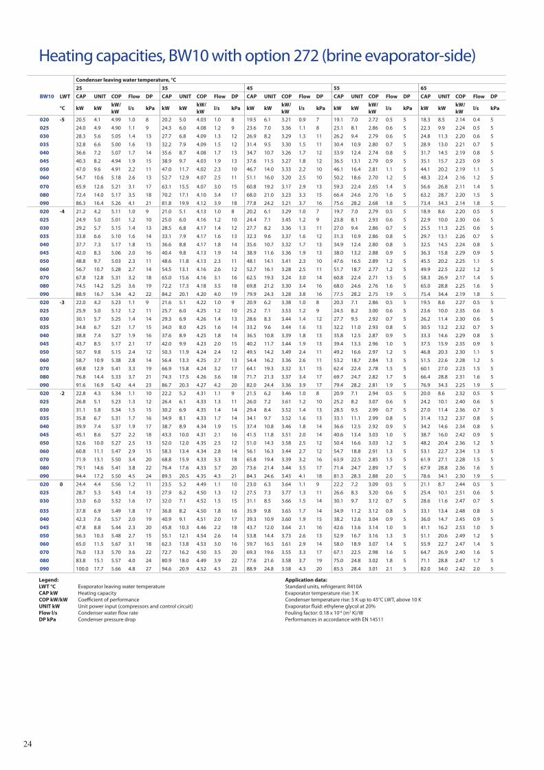
Heating capacities, BW10 with option 272 (brine evaporator-side)Condenser leaving water temperature, °C
25 35 45 55 65
BW10 LWT CAP UNIT COP Flow DP CAP UNIT COP Flow DP CAP UNIT COP Flow DP CAP UNIT COP Flow DP CAP UNIT COP Flow DP
°C kW kWkW/kW
l/s kPa kW kWkW/kW
l/s kPa kW kWkW/kW
l/s kPa kW kWkW/kW
l/s kPa kW kWkW/kW
l/s kPa
020 -5 20.5 4.1 4.99 1.0 8 20.2 5.0 4.03 1.0 8 19.5 6.1 3.21 0.9 7 19.1 7.0 2.72 0.5 5 18.3 8.5 2.14 0.4 5
025 24.0 4.9 4.90 1.1 9 24.3 6.0 4.08 1.2 9 23.6 7.0 3.36 1.1 8 23.1 8.1 2.86 0.6 5 22.3 9.9 2.24 0.5 5
030 28.3 5.6 5.05 1.4 13 27.7 6.8 4.09 1.3 12 26.9 8.2 3.29 1.3 11 26.2 9.4 2.79 0.6 5 24.8 11.3 2.20 0.6 5
035 32.8 6.6 5.00 1.6 13 32.2 7.9 4.09 1.5 12 31.4 9.5 3.30 1.5 11 30.4 10.9 2.80 0.7 5 28.9 13.0 2.21 0.7 5
040 36.6 7.2 5.07 1.7 14 35.6 8.7 4.08 1.7 13 34.7 10.7 3.26 1.7 12 33.9 12.4 2.74 0.8 5 31.7 14.5 2.19 0.8 5
045 40.3 8.2 4.94 1.9 15 38.9 9.7 4.03 1.9 13 37.6 11.5 3.27 1.8 12 36.5 13.1 2.79 0.9 5 35.1 15.7 2.23 0.9 5
050 47.0 9.6 4.91 2.2 11 47.0 11.7 4.02 2.3 10 46.7 14.0 3.33 2.2 10 46.1 16.4 2.81 1.1 5 44.1 20.2 2.19 1.1 5
060 54.7 10.6 5.18 2.6 13 52.7 12.9 4.07 2.5 11 51.1 16.0 3.20 2.5 10 50.2 18.6 2.70 1.2 5 48.3 22.4 2.16 1.2 5
070 65.9 12.6 5.21 3.1 17 63.1 15.5 4.07 3.0 15 60.8 19.2 3.17 2.9 13 59.3 22.4 2.65 1.4 5 56.6 26.8 2.11 1.4 5
080 72.4 14.0 5.17 3.5 18 70.2 17.1 4.10 3.4 17 68.0 21.0 3.23 3.3 15 66.4 24.6 2.70 1.6 5 63.2 28.7 2.20 1.5 5
090 86.3 16.4 5.26 4.1 21 81.8 19.9 4.12 3.9 18 77.8 24.2 3.21 3.7 16 75.6 28.2 2.68 1.8 5 73.4 34.3 2.14 1.8 5
020 -4 21.2 4.2 5.11 1.0 9 21.0 5.1 4.13 1.0 8 20.2 6.1 3.29 1.0 7 19.7 7.0 2.79 0.5 5 18.9 8.6 2.20 0.5 5
025 24.9 5.0 5.01 1.2 10 25.0 6.0 4.16 1.2 10 24.4 7.1 3.45 1.2 9 23.8 8.1 2.93 0.6 5 22.9 10.0 2.30 0.6 5
030 29.2 5.7 5.15 1.4 13 28.5 6.8 4.17 1.4 12 27.7 8.2 3.36 1.3 11 27.0 9.4 2.86 0.7 5 25.5 11.3 2.25 0.6 5
035 33.8 6.6 5.10 1.6 14 33.1 7.9 4.17 1.6 13 32.3 9.6 3.37 1.6 12 31.3 10.9 2.86 0.8 5 29.7 13.1 2.26 0.7 5
040 37.7 7.3 5.17 1.8 15 36.6 8.8 4.17 1.8 14 35.6 10.7 3.32 1.7 13 34.9 12.4 2.80 0.8 5 32.5 14.5 2.24 0.8 5
045 42.0 8.3 5.06 2.0 16 40.4 9.8 4.13 1.9 14 38.9 11.6 3.36 1.9 13 38.0 13.2 2.88 0.9 5 36.3 15.8 2.29 0.9 5
050 48.8 9.7 5.03 2.3 11 48.6 11.8 4.13 2.3 11 48.1 14.1 3.41 2.3 10 47.6 16.5 2.89 1.2 5 45.5 20.2 2.25 1.1 5
060 56.7 10.7 5.28 2.7 14 54.5 13.1 4.16 2.6 12 52.7 16.1 3.28 2.5 11 51.7 18.7 2.77 1.2 5 49.9 22.5 2.22 1.2 5
070 67.8 12.8 5.31 3.2 18 65.0 15.6 4.16 3.1 16 62.5 19.3 3.24 3.0 14 60.8 22.4 2.71 1.5 5 58.3 26.9 2.17 1.4 5
080 74.5 14.2 5.25 3.6 19 72.2 17.3 4.18 3.5 18 69.8 21.2 3.30 3.4 16 68.0 24.6 2.76 1.6 5 65.0 28.8 2.25 1.6 5
090 88.9 16.7 5.34 4.2 22 84.2 20.1 4.20 4.0 19 79.9 24.3 3.28 3.8 16 77.5 28.2 2.75 1.9 5 75.4 34.4 2.19 1.8 5
020 -3 22.0 4.2 5.23 1.1 9 21.6 5.1 4.22 1.0 9 20.9 6.2 3.38 1.0 8 20.3 7.1 2.86 0.5 5 19.5 8.6 2.27 0.5 5
025 25.9 5.0 5.12 1.2 11 25.7 6.0 4.25 1.2 10 25.2 7.1 3.53 1.2 9 24.5 8.2 3.00 0.6 5 23.6 10.0 2.35 0.6 5
030 30.1 5.7 5.25 1.4 14 29.3 6.9 4.26 1.4 13 28.6 8.3 3.44 1.4 12 27.7 9.5 2.92 0.7 5 26.2 11.4 2.30 0.6 5
035 34.8 6.7 5.21 1.7 15 34.0 8.0 4.25 1.6 14 33.2 9.6 3.44 1.6 13 32.2 11.0 2.93 0.8 5 30.5 13.2 2.32 0.7 5
040 38.8 7.4 5.27 1.9 16 37.6 8.9 4.25 1.8 14 36.5 10.8 3.39 1.8 13 35.8 12.5 2.87 0.9 5 33.3 14.6 2.29 0.8 5
045 43.7 8.5 5.17 2.1 17 42.0 9.9 4.23 2.0 15 40.2 11.7 3.44 1.9 13 39.4 13.3 2.96 1.0 5 37.5 15.9 2.35 0.9 5
050 50.7 9.8 5.15 2.4 12 50.3 11.9 4.24 2.4 12 49.5 14.2 3.49 2.4 11 49.2 16.6 2.97 1.2 5 46.8 20.3 2.30 1.1 5
060 58.7 10.9 5.38 2.8 14 56.4 13.3 4.25 2.7 13 54.4 16.2 3.36 2.6 11 53.2 18.7 2.84 1.3 5 51.5 22.6 2.28 1.2 5
070 69.8 12.9 5.41 3.3 19 66.9 15.8 4.24 3.2 17 64.1 19.3 3.32 3.1 15 62.4 22.4 2.78 1.5 5 60.1 27.0 2.23 1.5 5
080 76.8 14.4 5.33 3.7 21 74.3 17.5 4.26 3.6 18 71.7 21.3 3.37 3.4 17 69.7 24.7 2.82 1.7 5 66.4 28.8 2.31 1.6 5
090 91.6 16.9 5.42 4.4 23 86.7 20.3 4.27 4.2 20 82.0 24.4 3.36 3.9 17 79.4 28.2 2.81 1.9 5 76.9 34.3 2.25 1.9 5
020 -2 22.8 4.3 5.34 1.1 10 22.2 5.2 4.31 1.1 9 21.5 6.2 3.46 1.0 8 20.9 7.1 2.94 0.5 5 20.0 8.6 2.32 0.5 5
025 26.8 5.1 5.23 1.3 12 26.4 6.1 4.33 1.3 11 26.0 7.2 3.61 1.2 10 25.2 8.2 3.07 0.6 5 24.2 10.1 2.40 0.6 5
030 31.1 5.8 5.34 1.5 15 30.2 6.9 4.35 1.4 14 29.4 8.4 3.52 1.4 13 28.5 9.5 2.99 0.7 5 27.0 11.4 2.36 0.7 5
035 35.8 6.7 5.31 1.7 16 34.9 8.1 4.33 1.7 14 34.1 9.7 3.52 1.6 13 33.1 11.1 2.99 0.8 5 31.4 13.2 2.37 0.8 5
040 39.9 7.4 5.37 1.9 17 38.7 8.9 4.34 1.9 15 37.4 10.8 3.46 1.8 14 36.6 12.5 2.92 0.9 5 34.2 14.6 2.34 0.8 5
045 45.1 8.6 5.27 2.2 18 43.3 10.0 4.31 2.1 16 41.5 11.8 3.51 2.0 14 40.6 13.4 3.03 1.0 5 38.7 16.0 2.42 0.9 5
050 52.6 10.0 5.27 2.5 13 52.0 12.0 4.35 2.5 12 51.0 14.3 3.58 2.5 12 50.4 16.6 3.03 1.2 5 48.2 20.4 2.36 1.2 5
060 60.8 11.1 5.47 2.9 15 58.3 13.4 4.34 2.8 14 56.1 16.3 3.44 2.7 12 54.7 18.8 2.91 1.3 5 53.1 22.7 2.34 1.3 5
070 71.9 13.1 5.50 3.4 20 68.8 15.9 4.33 3.3 18 65.8 19.4 3.39 3.2 16 63.9 22.5 2.85 1.5 5 61.9 27.1 2.28 1.5 5
080 79.1 14.6 5.41 3.8 22 76.4 17.6 4.33 3.7 20 73.6 21.4 3.44 3.5 17 71.4 24.7 2.89 1.7 5 67.9 28.8 2.36 1.6 5
090 94.4 17.2 5.50 4.5 24 89.3 20.5 4.35 4.3 21 84.3 24.6 3.43 4.1 18 81.3 28.3 2.88 2.0 5 78.6 34.1 2.30 1.9 5
020 0 24.4 4.4 5.56 1.2 11 23.5 5.2 4.49 1.1 10 23.0 6.3 3.64 1.1 9 22.2 7.2 3.09 0.5 5 21.1 8.7 2.44 0.5 5
025 28.7 5.3 5.43 1.4 13 27.9 6.2 4.50 1.3 12 27.5 7.3 3.77 1.3 11 26.6 8.3 3.20 0.6 5 25.4 10.1 2.51 0.6 5
030 33.0 6.0 5.52 1.6 17 32.0 7.1 4.52 1.5 15 31.1 8.5 3.66 1.5 14 30.1 9.7 3.12 0.7 5 28.6 11.6 2.47 0.7 5
035 37.8 6.9 5.49 1.8 17 36.8 8.2 4.50 1.8 16 35.9 9.8 3.65 1.7 14 34.9 11.2 3.12 0.8 5 33.1 13.4 2.48 0.8 5
040 42.3 7.6 5.57 2.0 19 40.9 9.1 4.51 2.0 17 39.3 10.9 3.60 1.9 15 38.2 12.6 3.04 0.9 5 36.0 14.7 2.45 0.9 5
045 47.8 8.8 5.44 2.3 20 45.8 10.3 4.46 2.2 18 43.7 12.0 3.64 2.1 16 42.6 13.6 3.14 1.0 5 41.1 16.2 2.53 1.0 5
050 56.3 10.3 5.48 2.7 15 55.1 12.1 4.54 2.6 14 53.8 14.4 3.73 2.6 13 52.9 16.7 3.16 1.3 5 51.1 20.6 2.49 1.2 5
060 65.0 11.5 5.67 3.1 18 62.3 13.8 4.53 3.0 16 59.7 16.5 3.61 2.9 14 58.0 18.9 3.07 1.4 5 55.9 22.7 2.47 1.4 5
070 76.0 13.3 5.70 3.6 22 72.7 16.2 4.50 3.5 20 69.3 19.6 3.55 3.3 17 67.1 22.5 2.98 1.6 5 64.7 26.9 2.40 1.6 5
080 83.8 15.1 5.57 4.0 24 80.9 18.0 4.49 3.9 22 77.6 21.6 3.58 3.7 19 75.0 24.8 3.02 1.8 5 71.1 28.8 2.47 1.7 5
090 100.0 17.7 5.66 4.8 27 94.6 20.9 4.52 4.5 23 88.9 24.8 3.58 4.3 20 85.5 28.4 3.01 2.1 5 82.0 34.0 2.42 2.0 5
Legend: LWT °C Evaporator leaving water temperature CAP kW Heating capacity COP kW/kW Coefficient of performance UNIT kW Unit power input (compressors and control circuit) Flow l/s Condenser water flow rate DP kPa Condenser pressure drop
Application data: Standard units, refrigerant: R410A Evaporator temperature rise: 3 K Condenser temperature rise: 5 K up to 45°C LWT, above 10 K Evaporator fluid: ethylene glycol at 20% Fouling factor: 0.18 x 10⁻⁴ (m2 K)/W Performances in accordance with EN 14511
25
Variable water flow system (VWF)• Operatingmodeatpartload
Thecontrolsystemincludestwopart-loadoperatingmodes:- Constantoutletpressurecontrol- ConstantdeltaTcontrol.
1–ConstantunitoutletpressurecontrolThecontrolcontinuouslyactsonthepumpspeedtoensureaconstantoutletpressure.
Thissolutionissuitableforinstallationswithtwo-wayvalves.Whentheseclose,thewaterspeedwillaccelerateinthesystembranchesthatarestillopen.Forafixed-speedpumpthisresultsinanunnecessaryincreaseofthepressureatthepumpoutlet.
Theoutletpressurecontrolmodeensuresthateachcircuitbranchalwayshasauniformsupply,withoutunnecessaryenergywaste.
Inindustrialprocessessuchasplasticinjectionmoulding,thissolutionensuresthateachterminalunithasthecorrectpressuresupply.
2–ConstantdeltaTcontrolTheVWFalgorithmmaintainsaconstantdeltaTnomatterwhattheunitload,reducingtheflowratetotheminimum.
Thissolutioncanbeusedforsystemswithtwo-wayorthree-wayvalvesandachieveshigherenergysavingsthanthe“Constantunitoutletpressurecontrol”mode.Itissuitableforthemajorityofcomfortapplications.
Variablewaterflowisahydroniccontrolfunctionpackagethatpermitscontrolofthewaterflowrate.
TheVWFnotonlyensurescontrolatfullload,aspecificalgorithmlinkedtoanelectronicfrequencyconverteralsocontinuouslymodulatestheflowratetominimisepumpconsumptionatfullloadaswellaspartload.
Thehydronicmoduleincludespressuretransducersthatpermitintelligentmeasurementofthewaterflowrateandreal-timedisplayontheuserinterface.Alladjust-mentscanbemadedirectlyontheinterface,speedingupstart-upandmaintenance.
AsVWFactsdirectlyonthepump,thesystemnolongerrequiresthecontrolvalveattheunitoutlet.However,forapplicationswithtwo-wayvalvesabypasssystemmustbekepttoguaranteetheminimumflowrate.
Operating logic
• Full-loadsetpointTheflowratecontrolatfullloadusestheuserinterface,reducingthepumpspeed.Thisfirstcontrolsavesenergythatwouldnormallybedissipatedinthecontrolvalve.Forexample,ifthepressuresuppliedbythepumpisreducedby20%thepowerconsumptionofthepumpisreducedbythesameratio,comparedtoatraditionalinstallation.
26
Quality assurance
• Thewater-sourcedunitsshallbedesignedforindoorinstallationinaplantroom.
• Thewater-sourcedunitsshalluseozone-friendlyrefrigerantR410Aandincludescrollcompressors.
• ThedesignandmanufacturingsiteoftheunitsshallbecertifiedinaccordancewiththequalitymanagementsystemISO9001.
• ThedevelopmenttestsiteoftheunitsshallbecertifiedtothequalitymanagementsystemISO17025.
• ThedesignandmanufacturingsiteoftheunitsshallbecertifiedinaccordancewiththeenvironmentalmanagementsystemISO14001.
• ThepublishedperformancesfortheunitsshallbeEurovent-certifiedandallunitsarefactory-testedbeforeshipment.
• Theunitsshallmeetthefollowingproductqualitystandards:2006/42/EC,2006/95/EC,2004/108/CE,97/23/EEC,2002/95/CE"RoHS",2002/96/EC"WEEE",2005/32/EC"Ecodesign",EN14511.
BW10 product features
• Thehot-waterproductionunitshallhaveaheatingcapacityof_____kW,amaximumpowerinputof_____kWandaCOPof_____kW/kW.
• Theevaporatorleavingwatertemperatureshallbe_____°Cwithatemperaturedifferenceof_____Kandacondenserleavingwatertemperatureof_____°Cwithatemperaturedifferenceof_____K.
• Thehot-waterproductionunitshallbeabletoproducehotwaterupto65°Candcoldwatertoclass___inaccordancewithEurovent.
• Thehot-waterproductionunitshallhaveweathercompen-sationcontrol,controllinganeedlevalveandpermittinghot-waterproductionatasecondsetpointof_____°C,controlledbyaclock.
• Itshallcontrolasupplementary4-stageelectricheaterandbeabletomanageareliefboiler(heatpumpstopped).
• Asecondcirculationpumpshallbecontrolledbythehot-waterproductionunit.
• Theunitshallhavewaterconnectionsatthetop/backandafootprintsizeof_____m².
• Thehydronickit,locatedintheupperunitsectionshallincludeallrequiredhydroniccomponentsincludinganexpansiontankof_____litres.
• Thecirculationpumpshavefixedspeed/variablewaterflowwithaminimumfrequencyof25Hz.Theevaporatorwaterpressuredropshallbe_____kPaandthecondenserwaterpressuredropshallbe_____kPa.
Guide specification, BW10 • Allhydronicandrefrigerantcircuitcomponentsoftheunitshallbecompatiblewithacondenserleavingwatertemperatureof65°C.
• Theunitshallbestackableinpairs,controlledinmaster/slaveconfigurationforatotalcapacityof_____kW.
• Theunitshalloperatewith400V-3ph-50Hz(400V±10%)withoutneutralanditshallonlyhaveoneconnectionpoint.
• Themaincontrolpanelshallbeprotectedbyaglasspanelandshallonlybeopenedwithaspecialtool.
• Theunitcontrolcircuitvoltageshallbe24Vmaximum,suppliedbyafactory-installedtransformer.Thecompressorshallofferquickkeyedelectricalconnection.
• Theunitshallincludenumericalcontrol,withthepossibilityofremotecontrol.Itshallensurethecontrolofthecompressors,evaporatorandcondenserwaterpumpsandthefans(drycooler).
• Thenumericalcontrolshallincludeapatentedauto-adaptivealgorithmthatcontrolstheoperationofthecompressorsandpermanentlyadjuststotheapplicationcharacteristicsincludingthewaterloopinertia.
• Dangerouscompressorcyclesarereducedtosixperhour.
• Thecontrolmenusshallpermitdirectaccessdoallunitdataincludingthehistoryofpossiblefaults.


VDGFK102