BW -HSP KBS D 2018-12b 8103881g1 - Festo...Festo BW_-HSP 2018-12b English 3 1 Important user...
14
Brief description Waiting position type BW_-HSP – English 8103879 2018-12b [8103881] Waiting position
Transcript of BW -HSP KBS D 2018-12b 8103881g1 - Festo...Festo BW_-HSP 2018-12b English 3 1 Important user...

Briefdescription
Waiting positiontype BW_-HSP
– English
81038792018-12b[8103881]
Waiting position
Festo BW_-HSP 2018-12b 2
Translation of the original instructions
Documentation on the product
For all available product documentation
� www.festo.com/pk
Copyright:
Festo SE & Co.Ruiter Straße 8273734 Esslingen Germany
Internet: �http://www.festo.comE-Mail: �[email protected]
Reproduction, distribution or sale of this document or communication ofits contents to others without express authorization is prohibited. Offenders will be liable for damages. All rights reserved in the event thata patent, utility model or design patent is registered.
English 3 . . . . . . . . . . . . . . . . . . . . . . . . . . . . . . . . . . . . . . . . . . . .

Festo BW_-HSP 2018-12b English 3
1 Important user instructionsEnglish
When the double-acting actuator cylinder typeBWL-/BWR-HSP-... retracts, it pulls the vertical guide rail
of the handling module type HSP-... out of the left-hand
(A) or right-hand end position upwards into the waitingposition (B).
When the actuator cylinder moves out, the HSP-... canswing out of the waiting position (B) back into the starting
position (A) or the other end position (C). The actuator
cylinder type BWL-/BWR-HSP-... has been designed forpulling the vertical guide rail of the handling module type
HSP-... out of the work range.
z
y
BWL-... BWR-...
(A)
(B)
(C)
Conditions of use
� Observe the specified limits (e.g. pressures, forces,temperatures). Observe the ambient conditions at
your location.
� Pressurize your system slowly. Uncontrolled move
ments will not then occur.
� Use the product in its original state without undertak
ing any modifications.

Festo BW_-HSP 2018-12b English4
2 Fitting
� Use shut-off valves in order to make the system pressureless for installation and maintenance work.
For fastening to the HSP-...
1 2 BWL-HSP-16/25
1
2
BWL-HSP-12
Tightening torques
Type 1 2
BWL-/BWR-HSP-12 M4 3 Nm M3 1.2 Nm
BWL-/BWR-HSP-16 M5 6 Nm M4 1.2 Nm
BWL-/BWR-HSP-25 M5 6 Nm M5 3.0 Nm
Festo BW_-HSP 2018-12b English 5
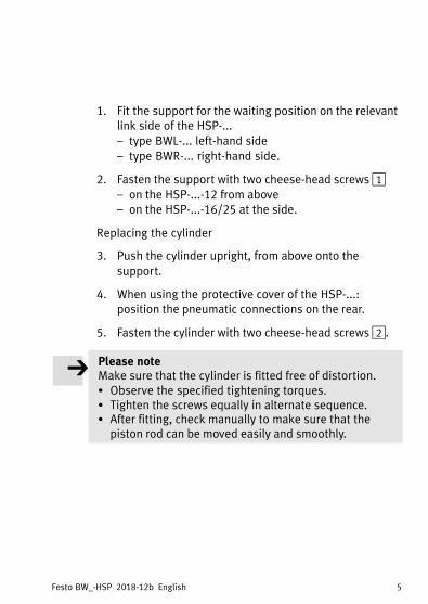
1. Fit the support for the waiting position on the relevantlink side of the HSP-...
– type BWL-... left-hand side
– type BWR-... right-hand side.
2. Fasten the support with two cheese-head screws 1– on the HSP-...-12 from above– on the HSP-...-16/25 at the side.
Replacing the cylinder
3. Push the cylinder upright, from above onto the
support.
4. When using the protective cover of the HSP-...: position the pneumatic connections on the rear.
5. Fasten the cylinder with two cheese-head screws 2.
Please noteMake sure that the cylinder is fitted free of distortion.� Observe the specified tightening torques.� Tighten the screws equally in alternate sequence.� After fitting, check manually to make sure that the
piston rod can be moved easily and smoothly.

Festo BW_-HSP 2018-12b English6
� Check in the end position the distance between crosslink 3 of the HSP-... and disc of the BWL-/BWR-HSP-...4.
With stop (distance < 1 mm):
1. Check the fastening of the BWL-/BWR-HSP-...
2. If necessary, loosen the hexagon nuts 5 and 6 for
readjustment.
3. Set a distance of 1..3 mm.
4. Tighten the locking nut 5 (see table).
Type Tightening torque 5
BWL-/BWR-HSP-12 M4 1.0 Nm
BWL-/BWR-HSP-16 M6 4.0 Nm
BWL-/BWR-HSP-25 M8 4.0 Nm

Festo BW_-HSP 2018-12b English 7
1−3m
m
3
5
67
4
3
4

Festo BW_-HSP 2018-12b English8
Fitting the pneumatic components
The cylinder is supplied fitted with built-in fixed restrictor(exhaust) for reducing the retraction speed and with quickconnectors type QSML-...�.
� Connect the pneumatic tubing to connection 7.
� Use e.g. the following components:
– a 5/2-way valve for actuating the cylinder (basic
position: cylinder extended)– a 5/3-way valve for actuating the drive of the HSP-...
(basic position: drive pressure-neutral)
– optional: additional restriction for reducing theretraction speed.
� Fasten the tubing outside the area of movement. Laythe tubing e.g. through the holes in the HSP-... to the
back 8.
Festo BW_-HSP 2018-12b English 9
8
9
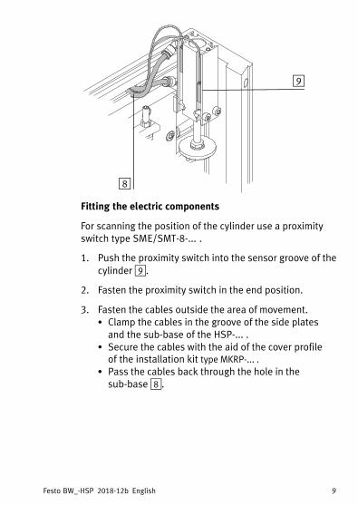
Fitting the electric components
For scanning the position of the cylinder use a proximityswitch type SME/SMT-8-... .
1. Push the proximity switch into the sensor groove of the
cylinder 9.
2. Fasten the proximity switch in the end position.
3. Fasten the cables outside the area of movement.� Clamp the cables in the groove of the side plates
and the sub-base of the HSP-... .� Secure the cables with the aid of the cover profile
of�the installation kit type MKRP-... .
� Pass the cables back through the hole in thesub-base 8.

Festo BW_-HSP 2018-12b English10
3 Commissioning
CautionDuring operation high dynamic forces arise which candamage the mechanical components.Make sure that the cylinder is extended when themounting cycle is started or continued (see table“Mounting cycle”).Make sure that movement to the waiting position isonly undertaken from the end position reached againstthe pressure-neutral rotary drive.� Pressurize the rotary drive via the 5/3-way valve in
both chambers before the cylinder is retracted.� Reset the 5/3-way valve to the basic position as soon
as the HSP-... reaches the end position again (starting position).
� Pressurize your system slowly.
� Observe the commissioning instructions in the manual
for the HSP-...�.
� Carry out a test run as described in the manual for the
HSP-...�.

Festo BW_-HSP 2018-12b English 11
Mounting cycle with BWL-HSP-...
ÓÓÓÓÓÓ ÓÓÓÓÓÓ1. Basic position:
HSP-... is in the left-hand end posi
tion. BWL-HSP... is extended. Drive
is pressure-neutral.
2. Waiting position:
BWL-HSP-... retracts and pulls the
vertical guide rail out of the work
range.
ÓÓÓÓÓÓ ÓÓÓÓÓÓ3. BWL-HSP-... is extended. 4. Mounting cycle is continued.

Festo BW_-HSP 2018-12b English12
4 Diagnosis
Fault Possible cause Remedy
Crosslink knocks
against disc
No gap been crosslink
and disc
Readjust gap
(1 ... 3 mm)
Uneven running – Bearing cover on
cylinder distorted
or
– Piston rod too dry
– Loosen screws, then
tighten again equally
– Lubricate the piston
rod

Festo BW_-HSP 2018-12b English 13
5 Technical specifications
BWL-/BWR-HSP-... 12 16 25
Weight [g] 75 170 310
Stroke-3 (z-direction) [mm] 15 25 25
Drive medium Filtered compressed air,
lubricated or non-lubricated
Filter fineness 40 ìm
Permitted operating pressure min. 4 ... max. 10 bar
Pneumatic connection
– Plug connector
(already fitted)
QSML-M3-3 QSML-M5-4
– Exhaust restriction (built-in) @ 0.3 mm @ 0.6 mm
Theoretical work force at 6 bar 40 N 104 N 158 N
Ambient temperature 0 ... + 60° C
Materials
– Support
– Disc
AL wrought alloy, anodized
Polyamide (PA66)
Cylinder
– End cover (bearing)
– Cylinder barrel
– Piston rod
– Seals
Brass
Aluminium
Steel, stainless
Polyurethane

Festo BW_-HSP 2018-12b English14