Bustrunking System Standard & Specifications Technical ...
20
1 INDEX Bustrunking System ……………………….. (1) Standard & Specifications ……………………….. (2) Technical Parameters Copper ……………………….. (3-4) Aluminum ……………………….. (5-6) Components Straight Length (Feeder & Plug in type) ……………………….. (7) Uniblock Joint, Edge Elbow & Offset Edge Elbow ……………………….. (8) Flat Elbow, Offset Flat Elbow & Flat Tee ……………………….. (9) Flanged End ……………………….. (10) Flange End with Flat Elbow & ……………………….. (11) Flange End with Edge Elbow ……………………….. (11) Flange End Box & Flange Bellow ……………………….. (12) Reducer & Sectional Isolator ……………………….. (13) Center Feed Unit & Copper Flexible ……………………….. (14) End Feed & End Cover ……………………….. (15) Vertical Support & Vertical Rigid Hanger ……………………….. (16) Vertical Spring Hanger ……………………….. (17) Horizontal Support ……………………….. (18) Plug in box ……………………….. (19) Domestic References ……………………….. ( ) International References ……………………….. ( ) Installation References ……………………….. ( ) Certificates ……………………….. ( )
Transcript of Bustrunking System Standard & Specifications Technical ...

1
INDEX
Bustrunking System ……………………….. (1)Standard & Specifications ……………………….. (2)Technical Parameters Copper ……………………….. (3-4) Aluminum ……………………….. (5-6)Components Straight Length (Feeder & Plug in type) ……………………….. (7) Uniblock Joint, Edge Elbow & Offset Edge Elbow ……………………….. (8) Flat Elbow, Offset Flat Elbow & Flat Tee ……………………….. (9) Flanged End ……………………….. (10) Flange End with Flat Elbow & ……………………….. (11) Flange End with Edge Elbow ……………………….. (11) Flange End Box & Flange Bellow ……………………….. (12) Reducer & Sectional Isolator ……………………….. (13) Center Feed Unit & Copper Flexible ……………………….. (14) End Feed & End Cover ……………………….. (15) Vertical Support & Vertical Rigid Hanger ……………………….. (16) Vertical Spring Hanger ……………………….. (17) Horizontal Support ……………………….. (18) Plug in box ……………………….. (19)Domestic References ……………………….. ( )International References ……………………….. ( )Installation References ……………………….. ( )Certificates ……………………….. ( )

2
GENERAL
GENERAL
SALIENT FEATURES
Busbar Trunking System for electricaldistribution is an alternative to cumbersomeconventional cable distribution system.
Busbar Trunking System has the advantage ofexpansions, Changes, replacement andreusing capability in the future.
Loads can be fed from Plug-in Box unlikecables, where each floor/ machine is to be fedseparately from the main switchboard.
Repositioning of distribution points is simpler.Installation time is much shorter then cablesystem. This provides low installation andmanpower costs and help for better timemanagement.
Busbar Trunking systems have a modern andaesthetic look.
System is maintenance free.
Close proximity of busbars reduces inductivereactance, resistance, impedance and voltagedrop is much lower than cable & any otherbusbar system.
Specially designed housing act as a heat sinkto yield improved thermal characteristic, highmechanical and short circuit strength.
Busbar System has no chimney effect, henceprovide a better resistance to the spread of fire.
Automatic polarity is maintained duringinstallation.
System can be mounted edgewise OR flat wisehorizontally or vertically in any direction with allkinds of bends and tees etc.
The compact structure and steel housingallows much lower electromagnetic field aroundbusbar system then cable.Busbars does notgenerate electromagnetic.

3
SPECIFICATIONS
Compliance of Standard Independent Certification Authority Busbar Arrangement Busbar Ratings Busbar Configuration Rated Operational Voltage (Ue) Rated Insulation Voltage (Ui) Rated Dielectric Voltage Rated Impulse Withstand Voltage (Uimp) Rated Frequency Enclosure Material Surface Coating on Enclosure Busbar Material (Phase/Neutral) Busbar Material (Internal Earth) Busbar Material (External Earth) Busbar Insulation Degree of Protection Joint Plug -in-Box
IEC 60439 (1&2) & IS 8623 (1&2) VMtec - Germany Sandwich Type Copper 630 ~ 6600A Aluminium 400 ~ 5000A 3 Phase+50% Internal Earth 3 Phase+100% Neutral+50% Internal Earth 3 Phase+200% Neutral+50% Internal Earth 3 Phase+100%Neutral+100% Isolated Earth +50%Internal Earth 1000 Volt, AC 1000 Volt, AC 3.5 KV r.m.s 12 kV (1.2/50 μs) 50 Hz / 60 Hz 1.6mm G.I Epoxy polyster powder coated (RAL-7032) Copper (full round edge ),99.9% pure ETP grade Aluminium (full round edge), 99.5% pure. G.I 1.5mm / Copper 1.5 mm. Copper / Aluminium Multi layer Class- 'F' Insulation (Polyster +Mica) IP 54 for Plug in type. IP55 / IP65 / IP67 for feeder bustrunking. Uniblock Joint (With Isolation and tamper proof shear off nut) 32~800 A

4
TECHNICAL PARAMETRS
SBC (Copper Sandwich Insulated Bus Trunking)
151 151 172 172
3 Phase+50%Internal Earth
3 Phase+100% Neutral+50% Internal Earth
3 Phase+200% Neutral+50% Internal Earth
3 Phase+100% Neutral+100%Isolated Earth+50% Internal Earth

5
TECHNICAL PARAMETRS
Voltage Drop Calculation Formulae
ΔV = k x 3 x ( Rt cos Ø + X sin Ø ) x IB x LWhereΔV is the composite voltage drop of the system (V);Rt & X are the mean resistance and reactance values ofthe system ("/m);IB is the actual load current of the circuit beingconsidered (A);
L is the length of the system beingconsidered (M);Cos Ø is the load power factor beingconsidered;k is the load distribution factor.k=1, if full load is concentred at theend of the busbar trunking run;
k=(n+1)/2n, if the load is uniformlyspread between n branches.

6
TECHNICAL PARAMETRS
SBA (Aluminium Sandwich Insulated Bus Trunking)151 151 172 172
3 Phase+50%Internal Earth
3 Phase+100% Neutral+50% Internal Earth
3 Phase+200% Neutral+50% Internal Earth
3 Phase+100% Neutral+100%Isolated Earth+50% Internal Earth

7
TECHNICAL PARAMETRS
Voltage Drop Calculation Formulae
ΔV = k x 3 x ( Rt cos Ø + X sin Ø ) x IB x LWhereΔV is the composite voltage drop of the system (V);Rt & X are the mean resistance and reactance values ofthe system ("/m);IB is the actual load current of the circuit beingconsidered (A);
L is the length of the system beingconsidered (M);Cos Ø is the load power factor beingconsidered;k is the load distribution factor.k=1, if full load is concentred at theend of the busbar trunking run;
k=(n+1)/2n, if the load is uniformlyspread between n branches.
8
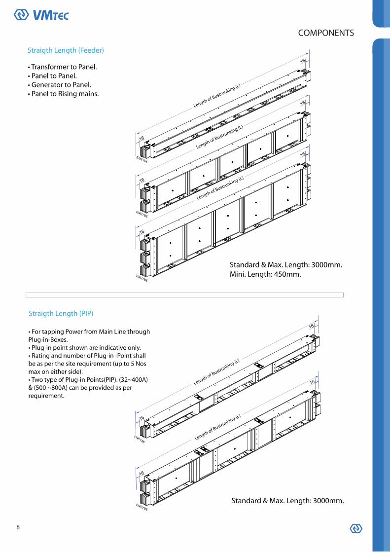
COMPONENTS
Straigth Length (Feeder)
• Transformer to Panel.• Panel to Panel.• Generator to Panel.• Panel to Rising mains.
Standard & Max. Length: 3000mm.Mini. Length: 450mm.
Straigth Length (PIP)
Standard & Max. Length: 3000mm.
• For tapping Power from Main Line throughPlug-in-Boxes.• Plug-in point shown are indicative only.• Rating and number of Plug-in -Point shallbe as per the site requirement (up to 5 Nosmax on either side).• Two type of Plug-in Points(PIP): (32~400A)& (500 ~800A) can be provided as perrequirement.
Length of Bustrunking (L)
Length of Bustrunking (L)
Length of Bustrunking (L)
Length of Bustrunking (L)
Length of Bustrunking (L)

9
COMPONENTS
Uniblock Joint
Edge Elbow
Offset Edge Elbow
Shear off nut
Current Rating
Aluminum 400~5000ACopper 630~6600A 300 x 300 x 300
Standard & Mini.Dimn.AxBxC (mm)
Current Rating
Aluminum 400~5000ACopper 630~6600A 300 x 300
Standard & Mini.Dimn.AxB (mm)
Joint can be fitted / removed in installed conditionwithout removal of section.• Heavy duty disc spring used on both sides forunifrom distribution of pressure.• Joint can be tightened easily with help of spanneron nut side only.(spanner not required on bolt headside)• Shear off nut ensure tightness of joint at desiredtorque and eliminates the need of torque wrenchduring installation.• Tamper proof cap over shear off nut preventsopening of nut after achieving desired torque.Nut can only be opened after breaking the cap.

10
COMPONENTSFlat Elbow
Offset Flat Elbow
Flat Tee
Aluminum 4000~5000ACopper 6000~6600A
Aluminum 2000~3600ACopper 3200~5000A
Aluminum 400~1800ACopper 630~2500A
Standard & Mini.Dimn. AxBxC (mm)Current Rating
500 x 500 x 600
600 x 600 x 600
400 x 400 x 400
Aluminum 4000~5000ACopper 6000~6600A
Aluminum 2000~3600ACopper 3200~5000A
Aluminum 400~1800ACopper 630~2500A
Standard & Mini.Dimn. AxBxC (mm)Current Rating
500 x 500 x 600
600 x 600 x 600
400 x 400 x 400
Aluminum 4000~5000ACopper 6000~6600A
Aluminum 2000~3600ACopper 3200~5000A
Aluminum 400~1800ACopper 630~2500A
Standard & Mini.Dimn. AxB (mm)Current Rating
500 x 500
600 x 600
400 x 400

11
COMPONENTS
Flanged End
BUSBAR WIDTH BUSBAR WIDTH BUSBAR WIDTH BUSBAR WIDTH40 ~ 80mm 100 ~ 125mm 150 ~ 175mm 200 ~ 230mm
300 Std. & Mini
Ø14) AS PER REQUIREMENTTERMINATION HOLES
Ø14) AS PER REQUIREMENTTERMINATION HOLES
Flanged End cut out & Drilling

12
COMPONENTS
Flanged End with Flat Elbow
Flanged End with Edge Elbow
Aluminum 4000~5000ACopper 6000~6600A
Aluminum 2000~3600ACopper 3200~5000A
Aluminum 400~1800ACopper 630~2500A
Current Rating Standard & Mini.Dimn. A x B (mm)
275 x 400
375 x 500
475 x 600
Copper 630~6600AAluminum 400~5000A 175 x 300
Current RatingStandard & Mini.Dimn. A x B (mm)

13
COMPONENTS
Flanged End Box
Aluminum 4000~5000ACopper 6000~6600AAluminum 2000~3600ACopper 3200~5000A
Aluminum 1350~1800ACopper 1800~2500A
Aluminum 400~1250ACopper 630~1600A
Current Rating STANDARD DIMENSIONSS.NO
800700
700
Flange Bellow need to be fixed between Flanged End Box and Genset termination box to avoid impact of vibrations of Genset being transferred to bustrunking.
Flange Bellow
Current RatingCurrent Rating
Standard Dimensions CodeS.
No
Copper 630~1600AAluminum 400~1250A
Copper 1800~2500AAluminum 1350~1800A
SFBE-3
CodeS.No
Copper 3200~5000AAluminum 2000~3600A
Current Rating
SFBE-4
CodeS.No
Copper 6000~6600AAluminum 4000~5000A

14
COMPONENTS
Reducer
Sectional Isolator
• These are required to isolate the bustrunking run inbetween, for various reasons. Section Isolator Unit can befitted with load Break Switches / SFU's / MCCB's.
Reducer (Switchgear)Reducer (Direct)
• These are required to connect two dissimilar rating ofbustrunking. Reducer may be designed with switching orisolating device.

15
COMPONENTS
Center Feed Unit
To charge bustrunking through cables from middle of bustrunking.• Center feed Unit is available with sufficient space for direct connection through lugs and bolts.MCCB,SFU, lsolators, fuse holders etc. can be fitted in Center Feed Unit as per requirement.• Undrilled cable gland plate is provided at bottom for multiple cable entry.
Center Feed Unit (Direct) Center Feed Unit (Switchgear)
Copper Flexible
• Copper Flexible need to be used to connect flanged endbusbar with busbars (Terminals) of Panel / Transformer /Generators.
Holes to be drilled at siteas per requirement
Switchgear side(Panel/D.G/TFR.)Bustrunking side
Thickness (t) & No of flexibleas per Rating
Tin Plated Braided Flexible

16
COMPONENTS
End Feed
• It is used to terminate and to protect the end of plug-in bustrunking(Rising mains run.)• It can be remove easily for extension of bustrunking .
End Cover
To charge bustrunking through cables from one end of bustrunking.• End feed is available with sufficient space for direct connection through lugs and bolts.MCCB,SFU, lsolators, fuse holders etc. can be fitted in End Feed as per requirement.• 300 mm length of bustrunking is integrally fitted (measured with bustrunking) along with EndFeed as standard practice so that joint between End Feed and bustrunking is exactly same asjoint of two normal bustrunking lengths.• Undrilled cable gland plate is provided at bottom for multiplecable entry.End Cover• It is used to terminate and to protect the end of plug-in bustrunking(Rising mains run.)• It can be remove easily for extension of bustrunking .End
End Feed (Direct) End Feed (Switchgear)

17
COMPONENTS
Vertical Support
Vertical support is used to control Horizontalmovement of sandwich rising main .
Vertical Rigid Hanger
One set of Rigid hanger per rising main must be installed at the start of the rising mains (i.e. At thelowest floor ) to prevent expansion of bustrunking in downward direction.These can be fitted on 100x50X5(or equivalent) channels mounted on floor / wall as shown below (not in scope of C&S supply)Recommendation for using hangers per floor:-• Up to 3.5 M: 01 rigid hanger.• 3.5M >4.5 M: 01 rigid hanger + 01 Vertical support. (for ensuring vertical alignment of risingmains.)• 4.5 m > 6.0 M: 02 rigid hanger
Installation Sequence
• Remove Nut A from Rigid Hanger on both sides.• Mount " Hanger Support" through 2Nos. Ø 13 predrilled holes provided on desired rising mainsection.• Insert "Rigid hanger bolts" into C-channel (already fixed at the floor level with desired holes)• Adjust Nut B on to the C-channel (on both sides parallely) ensuring center line ( ) of rigidhanger support positioned as 175 mm from floor level (or as indicated in drawing )• Tighten & lock nut A.• Ensure nut “C” remains fully tightened during entire process.
Copper 630A~1250A Aluminum 400A~1800A
Copper 1600A~ 2500AAluminum 2000A~ 5000A
Copper 3200A ~ 5000A
C-Channel With Ø14holes not in scope of C&SSupply(100x50x5)
Rigid hangerBolt
Hanger support

18
COMPONENTS
Vertical Spring Hanger
One set of Spring hanger per rising main per floor (excluding lowest floor) need to be installed tosustain the bustrunking load and to allow vertical expansion of bustrunking in upward directiononly.These can be fitted on 100x50X5 (or equivalent) channels mounted on floors / walls as shownbelow (not in scope of C&S supply)Recommendation for using hangers per floor:-• Up to 3.5 M: 01 Vertical spring hanger .• 3.5M >4.5 M: 01 Vertical spring hanger + 01 Vertical support. ((for ensuring vertical alignmentof rising mains.)• 4.5 M > 6.0 M: 02 Vertical spring hanger.
SVSH-1 SVSH-2 SVSH-3
Nut D
Nut C1Nut C2Nut BNut А
107.5 107.5
325
300
175
100
325
300
175
100
325
300
175
100
215
• Remove nut A from spring hanger on both sides.• Mount " Hanger support" through 2 Nos. Ø13 predrilled holes provided on desired Rising mainsection.• Insert "Spring hanger bolts" into C-channel (already fixed at the floor level with desired holes )• Adjust nut B on to the C-Channel ensuring center line ( ) of Hanger Support positioned at 300mm from floor level (or as indicated in drawing )• If two section are required at any floor, then (join) upper section with lower section (fitted withspring hanger) so that entire weight of rising main for that floor falls on spring hanger.• open & bring down nut C1 & C2 slowly (on both sides parallely) until a gap of 1~2mm is createdbetween nut D and spring hanger support• Lock nut C1 & C2 at this position• Loosen Nut D for allowing thermal expansion of rising main.
Instalation Sequense

19
COMPONENTS
Edgewise Horizontal Support
250
400
650
850
300
450
700
900
SFHS-1
SFHS-2
SFHS-3
SFHS-4
Current RatingStandard Dimensions
A BCode Detail
Ø12 Rod *
Ø12 Rod * Ø12 Rod *
A A A
Ø12 Rod *
Ø12 Rod *
Ø12 Rod *
250300
250300
250300
(SEHS-1) (SEHS-1) (SEHS-1)* Not in scope of C&S Supply
* Not in scope of C&S Supply
Flatwise Horizontal Support
These support need to be provided on horizontal feeder run at an intervalof 1.5 M (or as per site requirement)
These support need to be provided on horizontal feeder run at an intervalof 1.5 M (or as per site requirement)

20
COMPONENTS
Plug-in-Box
Plug in box enclosure is made from G.I with side hinged door.• Plug in contacts are made out of silver plated copper with spring steel backup pressure clips forensuring uniform pressure and low contact resistance .• For cables entry, provision of gland plates are provided on both sides and bottom of Plug in Box.• Earth contact of Plug-in boxes makes first & breaks last.• Plug in box are suitable for MCCB/SFU’s with rotary handle and door interlocking.• Plug in boxes are available with Interlocking with bustrunking to ensure "plug-in" and "Plug-Out"possible only in "Off" Condition.• Silver Plated contacts are properly shrouded / isolated.• Plug in box up to 400 A are compatible to all ratings of Bustrunking with 400 A Plug-in-points• Plug in box from 500A to 800 A are compatible to all ratings of Bustrunking with 800 A plug inpoints.• Plug in boxes can only be fitted on to the Bustrunking with corrected polarity i.e. ENRYBE.
Fig.-1 Fig.-2 Fig.-3Fig.-4
* Available with Isolater.
PIB with subcode 4B is applicable for-• 3 Phase+50% Internal Earth • 3 Phase+200% Neutral +50% Internal Earth• 3 Phase+100% Neutral +50% Internal Earth • 3 Phase+100% Neutral+100% Isolated Earth+50% Internal Earth