BUSMODUL DEVICENET - Advanced Energy · • The bus module is a slave component with DeviceNet...
55
BUSMODUL DEVICENET FOR THYRO-S, THYRO-A AND THYRO-AX July 2014 DE/EN - V3
Transcript of BUSMODUL DEVICENET - Advanced Energy · • The bus module is a slave component with DeviceNet...

1
BUSMODUL DEVICENET fOr ThyrO-S, ThyrO-A AND ThyrO-AX
July 2014 DE/EN - V3

2
CONTACT
TEChNICAL qUErIESDo you have any technical queries regarding the subjects dealt with inthese operating instructions?If so, please get in touch with our team for power controllers:Phone +49 (0) 2902 763-520
COMMErCIAL qUErIESDo you have any commercial queries on power controllers?If so, please get in touch with our team for power controllers.Phone +49 (0) 2902 763-558
SErVICE-hOTLINEAdvanced Energy Industries GmbhBranch Office Warstein-BeleckeEmil-Siepmann-Straße 32D-59581 WarsteinPhone +49 (0) 2902 763-0http://www.advanced-energy.com
COPyrIGhTNo part of these operating instructions may be transmitted, reproduced and/or copied by any electronic or mechanical means without the express prior written permission of Advanced Energy.© Copyright Advanced Energy Industries Gmbh 2014.All rights reserved.
fUrThEr INfOrMATION ON COPyrIGhTThyro-™, Thyro-S™, Thyro-A™, Thyro-AX™ are registered trademarks of Advanced Energy Industries Gmbh. All other company and product names are (registered) trademarks of the respective owners.

3
1. General 6
1.1 Type designations/Validity 6
1.2. Specific features 7
1.3. Warranty 7
2. Safety 8
2.1 Identification in the operating instructions 8
2.2 General danger information 9
2.3 Operator requirements 10
2.4 Personnel requirements 10
2.5 Intended purpose 10
2.6 Use of the device 11
2.6.1 Operation 11
2.6.2 Prior to installation/start-up 11
2.6.3 Maintenance, service, faults 11
2.6.4 Transport 11
3. functions 12
3.1 Setpoint processing Thyro-S 12
3.2 Setpoint processing Thyro-A/Thyro-AX 12
3.3 freely addressable digital outputs (Thyro-S, Thyro-A and Thyro-AX) 13
4. Installation 14
4.1 Connection terminals (Overview) 14
4.2 Connecting 24 V power supply 14
4.3 Connecting power controller to X1-X8 15
4.4 Connecting the bus module to the master 15
5. Setup 17
5.1 Setup the slots count 17
5.2 Setup the node address 17
5.3 Setup the communication speed 18
5.4 DeviceNet scanner and bus module setup 18
TABLE Of CONTENTS

4
6. Object Specifications 21
6.1 0x01 Identity Object 21
6.2 0x02 Message router Object 22
6.3 0x03 DeviceNet Object 22
6.4 0x04 Assembly Object 23
6.5 0x05 Connection Class 24
6.6 0x0f Parameter Object 26
6.7 0x64 Vendor specific classes of the bus module 27
6.8 0x65-0x66 Vendor specific classes for Thyro-S/Thyro-A/Thyro-AX 28
7. DeviceNet status LEDs 29
8. Assembly 31
8.1 Assembly 101: Setpoint (Output for Poll) 31
8.2 Assembly 102: Setpoint, State... (Input for Poll) 32
8.3 Assembly 103: Actual value power 32
8.4 Assembly 104: Actual value voltage load 33
8.5 Assembly 105: Actual value current 33
8.6 Assembly 106: voltage main 33
9. Vendor specific Attributes 34
9.1 Attributes of Class 0x64 34
9.2 Attributes of Class 0x65 35
9.3 Attributes of Class 0x66 39
10. Connection diagrams 46
11. help in the event of problems 49
12. Technical data 50
13. Dimensional drawing 51
14. Accessories and options 52
15. Approvals and conformity 52
5
fig. 4.1 Wiring connection 16fig. 5.1 Configuration & LEDs 18fig. 5.2 Up-/download chassis configuration 19fig. 5.3 Module configuration 20
Tab. 4.1 Connection terminals (Overview) 14Tab. 6.1 Identity Object Class Attributes 21Tab. 6.2 Identity Object Instance Attributes 21Tab. 6.3 Identity Object Services 22Tab. 6.4 DeviceNet Object Class Attributes 22Tab. 6.5 DeviceNet Object Instance Attributes 22Tab. 6.6 DeviceNet Object Services 23Tab. 6.7 Assembly Object Class Attributes 23Tab. 6.8 Assembly Object Instance Attributes 23Tab. 6.9 Assembly Object Services 23Tab. 6.10 Connection Class Instances 24Tab. 6.11 Connection Class Attributes 24Tab. 6.12 Connection Class Instance Attributes 25Tab. 6.13 Connection Class Services 26Tab. 6.14 Parameter Class Attributes 26Tab. 6.15 Parameter Class Services 27Tab. 6.16 Bus module attributes 27Tab. 6.17 Vendor specific Objects Class Attributes 27Tab. 6.18 Vendor specific Object Services 27Tab. 6.19 Thyro-S, Thyro-A and Thyro-AX attributes 28Tab. 6.20 Vendor specific Objects Class Attributes 28Tab. 6.21 Vendor specific Object Services 28Tab. 7.1 Module Status LED 29Tab. 7.2 Network Status LED 30Tab. 8.1 Output Assembly 101 31Tab. 8.2 Interpretation of the master setpoint for Thyro-S 31Tab. 8.3 Input Assembly 102 32Tab. 8.4 Input Assembly 103 32Tab. 8.5 Input Assembly 104 33Tab. 8.6 Input Assembly 105 33Tab. 8.7 Input Assembly 106 33Tab. 9.1 Configured device type 34Tab. 9.2 Current device type 34Tab. 9.3 Power controller type 35Tab. 9.4 Bus module setup 35Tab. 9.5 Digital out 35Tab. 9.6 Setpoints 35Tab. 9.7 function 39Tab. 9.8 hardware parameter 39
LIST Of ILLUSTrATIONS AND TABLES
6
1. GENErAL
This bus module is for controlling Advanced Energy thyristor power control-lers over DeviceNet. Particularly where several power controllers are used at the same time, inexpensive solutions and improvements can be made in the following areas:- Process flow- Process documentation- Start-up and costs- System availability- WiringThese operating instructions are a supplement to the operating instructions for Advanced Energy Thyro-S thyristor power controllers of types ...h1 and...h rL1 as well as Thyro-A ...h1, ...h rL1 and ...h rLP1 as well as Thyro-AX ...h rL2 and ...h rLP2.The DeviceNet bus module can connect up to 8 Thyro-AX...2, Thyro-A...1 or Thyro-S...1 power controllers in any combination to a DeviceNet scanner. Several bus modules can be used in one system. Each bus module occupies one address on the bus.These operating instructions describe the configuration and functions of the bus module DeviceNet and are designed to enable qualified personnel to perform the following work:- Planning- Start-up
Information and explanations for unqualified persons and for the use in non-industrial applications are not included in these operating instructions.
1.1 TyPE DESIGNATIONS/VALIDITyThese operating instructions describe the bus module DeviceNet (OrderNo. 2000 000 844). These operating instructions comply with the current technical specifications of the device at the time of publication. The contents do not constitute a subject matter of the contract, but serve for information purposes only. We reserve the right to alter any specifications given in these operating instructions, especially with regard to technical data, operation, weights and dimensions. Advanced Energy reserves the right to make mo-difications with regard to the content and technical data in these operating instructions.

7
1.2 SPECIfIC fEATUrES• The bus module is a slave component with DeviceNet functionality.• Function control via modulo and network LED• 8 free application outputs X1 to X8 in each case terminal 5• Processing of actual values as float number in physical units• C-rail assembly• When the bus module is linked to Thyro-AX, please be aware that data trans-
fer is the same as for Thyro-A whereas special features or other additional parameters are excluded from this.
1.3 WArrANTyIn the event of any claims in connection with the DeviceNet, please contact us immediately quoting:- Type designation- Works number/Serial number- reason for the complaint- Environmental conditions of the device- Operating mode- Period of use
Goods and services are subject to the general conditions of supply forproducts of the electrical industry, and our general sales conditions.Claims in connection with supplied goods must be submitted within one week of receipt, along with the delivery note. Advanced Energy will rescind all obligations such as warranty agreements, service contracts, etc. entered into by Advanced Energy or its representatives without prior notice if main-tenance and repair work is carried out using anything other than original Ad-vanced Energy spare parts or spare parts purchased from Advanced Energy .

8
2. SAfETy
2.1 IDENTIfICATION IN ThE OPErATING INSTrUCTIONSIn these operating instructions, there are warnings before dangerousactions. These warnings are divided into the following danger categories:
DANGErDangers that can lead to serious injuries or fatal injuries.
WArNINGDangers that can lead to serious injuries or considerable damage to property.
CAUTIONDangers that can lead to injuries and damage to property.
CAUTIONDangers that can lead to minor damage to property.
The warnings can also be supplemented with a special danger symbol(e.g. „Electric current“ or „hot parts“), e.g.
risk of electric current or
risk of burns.

9
In addition to the warnings, there is also a general note for useful information.
NOTEContent of note
2.2 GENErAL DANGEr INfOrMATION
DANGEr failure to observe the safety regulations in the operating instructions for the power controllers used risk of injury or damage to the device or plant.> Observe all safety regulations in the safety chapter of the operating instruc-
tions for the power controllers used.
DANGErElectric current risk of injury from live parts/risk of damage to the bus module> Never operate the device without the cover.> Only carry out adjustments or wiring when the device is deenergised.
CAUTIONrisk of damage to the bus moduleThe current at terminals X1.5 to X8.5 may not exceed 120 mA.> Check the connection data of the upstream relay.
NOTECommunication faultsTo avoid communication faults, observe the following points:> Use shielded cables.> Ensure grounding on the bus module (X1.7 to X8.7). Do not also ground on
the power controller.

10
2.3 OPErATOr rEqUIrEMENTSThe operator must ensure the following:- That the safety regulations of the operating instructions are observed.- That the accident prevention regulations valid in the respective country of
use and the general safety regulations are observed.- That all safety devices (covers, warning signs etc.) are present, in perfect
condition and are used correctly.- That national and regional safety regulations are observed.- That the personnel has access to the operating instructions and safety
regulations at all times.- That operating conditions and restrictions resulting from the technical data
are observed.- That, should abnormal voltages, noises, increased temperatures,
vibration or similar occur, the device is immediately put out of opera-tion and the maintenance personnel is informed.
2.4 PErSONNEL rEqUIrEMENTSOnly qualified electro-technical personnel who are familiar with the pertinent safety and installation regulations may perform the following:- Transport- Installation- Connection- Start-up- Maintenance- Testing- Operation.
These operating instructions must be read carefully by all personsworking with or on the equipment prior to installation and initial start-up.
2.5 INTENDED PUrPOSEThe device may only be used for the pupose for which it was intended,as persons may otherwise be exposed to dangers (e.g. electric shock,burns) and plants also (e.g. overload). The user must therefore observethe following points:- It is not permitted to make any unauthorised modifications to the unit or to
use any spare parts or replacement parts not approved by Advanced Energy, or to use the unit for any other purpose.
- The warranty obligations of the manufacturer are only applicable if these

11
operating instructions are observed and complied with.- The device is a component that cannot function alone.- Project planning must account for the proper use of the device.
2.6 USE Of ThE DEVICE
2.6.1 OPErATION- Only switch on the mains voltage at the machine when there is no danger to
persons, system or load.- Protect the device against dust and damp.- Ensure that the ventilation openings are not blocked.
2.6.2 PrIOr TO INSTALLATION/STArT-UP- If stored in a cold environment: ensure that the device is absolutely dry.
(Allow the device a period of at least two hours to acclimatise before start-up.)
- Ensure sufficient ventilation of the cubicle if mounted in a cubicle.- Observe minimum spacing.- Ensure that the device cannot be heated up by heat sources below it (see
chapter 12, Technical data).- Ground the device in accordance with local regulations.- Connect the device in accordance with the connection diagram.
2.6.3 MAINTENANCE, SErVICE, fAULTSIn order to avoid injuries and damage, the user must observe thefollowing:- Before all work: > Disconnect the device from all external voltage sources. > Secure the device against accidentally being switched back on. > Use suitable measuring instruments and check that there is no vol-tage
present. > Ground and short-circuit the device. > Provide protection by covers or barriers for any neighbouring live parts.- The device may only be serviced and repaired by trained electrotechnical
personnel.
2.6.4 TrANSPOrT- Only transport the device in the original packaging.- Protect the device against damage caused, for instance, by jolts, knocks and
contamination.

12
3. fUNCTIONS
3.1 SETPOINT PrOCESSING Thyro-SAnalog signal from control terminal X22.1 of the power controller> Do not make any connection at terminal X22.4 of the power controller.– The bus module is fully functional. The analog signal from control terminal
X22.1 is used as setpoint (on/off).
Setpoint from bus module> Connect ground to terminal X22.4 of the power controller.– The master setpoint of the bus module is used. for this the setpoint is inter-
preted as operating mode (Table 8.2).
Use setpoint from bus module only if an IO-Connection is established.> Connect terminal X22.4 of the power controller to one of the terminals X1.1
to X8.1 of the bus module.– If an IO-Connection is established the setpoint master is used.
If not, the analog signal from control terminal X22.1 is used as setpoint (on/off).
Individual setpoint from the bus module for each power controller> Connect terminal X22.4 of the power controller to one of the terminals X1.5
to X8.5 of the bus module.– The power controllers can be switched individually (selectively) via the bus
between master setpoint and terminal X22.1.
3.2 SETPOINT PrOCESSING Thyro-A/Thyro-AXAnalog signal from control terminal X2.4 of the power controller> Do not make any connection at terminal X22.1 of the power controller.– The bus module is fully functional. The analog signal from control terminal
X2.4 is used as setpoint.
Setpoint from bus module> Connect ground to terminal X22.1 of the power controller.– The master setpoint of the bus module is used.

13
Setpoint from bus module only if an IO-Connection is established> Connect terminal X22.1 of the power controller to one of the terminals X1.1
to X8.1 of the bus module.– If an IO-Connection is established the setpoint master is used.
If not, the analog signal from control terminal X2.4 is used as setpoint.
Individual setpoint from the bus module for each power controller> Connect terminal X22.1 of the power controller to one of the terminals X1.5
to X8.5 of the bus module.– The power controllers can be switched individually (selectively) via the bus
between master setpoint and terminal X2.4.
3.3 frEELy ADDrESSABLE DIGITAL OUTPUTS(Thyro-S, Thyro-A AND Thyro-AX)> Do not occupy terminals X1.5 to X8.5 of the bus module.> Connect relay with 24 V DC coil voltage for free use. - The idle circuit is integrated. The drive current is max. 120 mA per output. - With this it is possible to switch cubicle fans, anti-condensation heating,
circuit breakers or control lamps, for example via the bus.
rELAy CONTrOL

14
4. INSTALLATION
DANGErDangers during installationrisk of injury/risk of damage to the device or plant> Observe all safety regulations in the safety chapter.
4.1 CONNECTION TErMINALS (OVErVIEW)
TErMINAL DESCrIPTION
X11 .1 24 V (+)
.2 24 V (Ground)
.3 Earthing
X1 - X8 .1 Total ground connected
.2 rxD
.3 TxD
.4 Ground
.5 Individually connectable ground
.6 Ground
.7 Ground potential for shield connection
X20 .1 V-
.2 CAN_L
.3 Shield
.4 CAN_h
.5 V+
TAB. 4.1 CONNECTION TErMINALS (OVErVIEW)
for further details see chapter 10 Connection diagram
4.2 CONNECTING 24 V POWEr SUPPLy> Switch off mains supply incl. external 24 V voltage source and secure
against accidentally being switched back on.> Connect external 24 V DC voltage source (150 mA) to X11.1 (+) and
X11.2 (ground) (polarity protection).> Keep grounding to terminal X11.3 as short as possible (EMC reasons).

15
NOTE24V DC supplySeveral bus modules can be operated with one power supply.> Make 24 V DC supply earth-free in SELV cases
4.3 CONNECTING POWEr CONTrOLLEr TO X1-X8> Switch off mains supply incl. external 24 V voltage source and secure
against accidentally being switched back on.> Connect interfaces X1 to X8 of the bus module to the system interfaces of
the power controller (4-wire shielded cable).
NOTECharacteristics of the system interface- The transmission rate is 38 400 Baud.- The asynchronous characters are transmitted with 8 bits, no parity and one
stop bit.- The protocol starts with STX, followed by an ID and the data, and is ended
with a check sum.- faulty protocols are ignored.
Attention: for control of all parameter over DeviceNet it is recommendthat the Thyro-A/Thyro-AX switches S1.3, S1.4, S1.5 are closed (Thyro-Tool mode).
4.4 CONNECTING ThE BUS MODULE TO ThE MASTEr> Switch off mains supply incl. external 24 V voltage supply and secure
against accidentally being switched back on.> Make the DeviceNet connection to X20 using a 5-pin open-style connector.
fit both ends of the bus cable with termination resistors of 120 Ω. The DeviceNet cable selection, cable routing, shielding, bus connec-tor, bus termination and transmission times are all described in the “Device-Net specification, volumes I, II“, published by ODVA. for connection to the DeviceNet we deliver with the card a standard openstyle connector. figure 4.1 shows how to connect the bus module to the DeviceNet.

16
fIG. 4.1 WIrING CONNECTION

17
5. SETUP
5.1 SETUP ThE SLOTS COUNTWith the rotary switch “Slots” the number of power controllers has tobe set. After changing the switch “Slots” and power on, the bus module reads all parameters from the power controllers and saves it into nonvolatile memory. After reading the parameter the device starts to communicate via DeviceNet. Therefore all power controllers must be connected und switched on at the first time.If one power controller is not correctly connected or has no supply thefault LED starts to flash. The number of flashes reflects the port wherethe error is. for example when the LED is repeatedly flashing twice thepower controller at X2 is not connected and has no power supply.
Attention: The rotary switch “Slots” take effect at the time of power-up. Changes to the switch settings of a powered device do not take effect until the next power-up.To restart this procedure- Change the switch “Slots” to a different position- Switch the power supply on for 2 seconds- Change the switch “Slots” to the correct position- Switch the power supply on.
5.2 SETUP ThE NODE ADDrESSAll devices connected to the DeviceNet bus must have a unique nodeaddress (NA), ranging from 0 to 63 (decimal). The node address can beset by the rotary switches “MSD” and “LSD”. Every address greater than 63 will be interpreted as node address 63.

18
fIG. 5.1 CONfIGUrATION & LEDS
1 Terminal X12 Terminal X23 Terminal X34 Terminal X45 Terminal X56 Terminal X67 Terminal X78 Terminal X89 Terminal X20 DeviceNet
10 Terminal X1111 Module status LED12 Network status LED13 Power LED14 fault LED15 Switch Slots16 Switch node address MSD17 Switch node address LSD
5.3 SETUP ThE COMMUNICATION SPEEDThis device detects the communication speed of the DeviceNet. So noadjustment has to be made. The communication speed 125, 250 and 500 kBaud are supported.
5.4 DEVICENET SCANNEr AND BUS MODULE SETUPSoftware configuration of the DeviceNet network and the associatedDeviceNet master requires an EDS file (electronic data sheet) for configuring each DeviceNet node. Therefore, register the EDS-file, which isdelivered with the bus module, with the configuration tool. After installing the EDS file scan the network for any attached nodes.
The node address cannot be changed via DeviceNet.

19
Next step is to upload the parameter of the bus module. for this openthe bus module properties, click on tab “Module Configuration”. In thedialog (figure 5.2) click on upload.
Attention: first of all the user should always initiate an upload before starting any setting-up operation (DeviceNet scanner and bus module).After uploading the parameter a dialog is shown, like figure 5.3.
fIG. 5.2 UP-/DOWNLOAD ChASSIS CONfIGUrATION
20
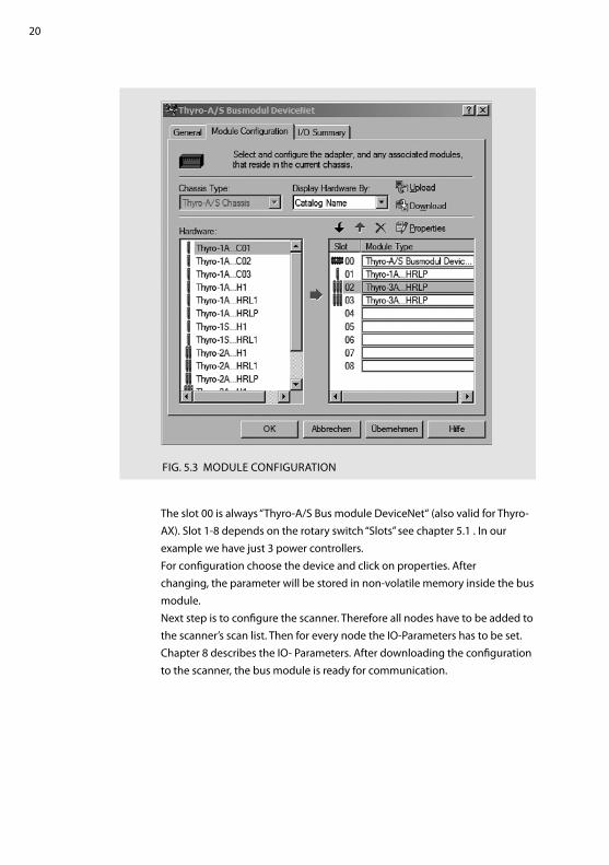
fIG. 5.3 MODULE CONfIGUrATION
The slot 00 is always “Thyro-A/S Bus module DeviceNet“ (also valid for Thyro-AX). Slot 1-8 depends on the rotary switch “Slots” see chapter 5.1 . In our example we have just 3 power controllers.for configuration choose the device and click on properties. After changing, the parameter will be stored in non-volatile memory inside the bus module.Next step is to configure the scanner. Therefore all nodes have to be added to the scanner’s scan list. Then for every node the IO-Parameters has to be set. Chapter 8 describes the IO- Parameters. After downloading the configuration to the scanner, the bus module is ready for communication.

21
6. OBJECT SPECIfICATIONS
6.1 0X01 IDENTITy OBJECTThis object provides identification of and general information about thedevice.
ATTr ID ACCESS
rULE
NAME DATA TyPE DESCrIPTION Of ATTrIBUTE SEMANTICS Of VALUES DEfAULT
1 Get revision UINT revision of this object. If updates that require an
increase 1 in this value are made,
then the value of this attribute
increases by 1.
1
2 Get Max Instance UINT Maximum instance number of an
object currently created in this
class level of the device.
The largest instance number
of a created object at this class
hierarchy level.
1
TAB. 6.1 IDENTITy OBJECT CLASS ATTrIBUTES
ATTr ACCESS
rULE
NAME DATA TyPE DESCrIPTION Of ATTrIBUTE DEfAULT
1 Get Vendor ID UINT Identification of vendor by number 1017
2 Get Device Type UINT Indication of general type of product. This device is a com-
munications adapter.
12
3 Get Product Code UINT Identification of a particular product of an individual vendor 3
4 Get revision STrUCT of: revision of the item the Identity Object represents.
Major revision USINT 1
Minor revision USINT 1
5 Get Status WOrD Summary status of device 1
6 Get Serial Number DINT Serial number of device 1
7 Get Product Name ShOrT_
STrING
human-readable identification Busmodule
DeviceNet
Thyro-S/Thyro-A/
Thyro-AX
8 Get State USINT Present state of the device
10 Get/Set heartbeat Interval USINT The nominal interval between heartbeat messages in
seconds
0
TAB. 6.2 IDENTITy OBJECT INSTANCE ATTrIBUTES

22
SErVICE CODE
SUPPOrTED SErVICE NAME DESCrIPTION Of SErVICECLASS INSTANCE
0x0E yes yes Get_Attribute_Single returns the content of the specified attribute.
0x10 N/A yes Set_Attribute_Single Modifies a DeviceNet Object attribute value.
0x05 N/A yes reset Invokes the reset service for the device.
TAB. 6.3 IDENTITy OBJECT SErVICES
6.2 0X02 MESSAGE rOUTEr OBJECTThe Message router is implemented as an Object that has no externally visible Attributes or Services. It only implements a behavior.
6.3 0X03 DEVICENET OBJECTThe DeviceNet Object provides the configuration and status of a DeviceNet port.
ATTr ID ACCESS
rULE
NAME DATA TyPE DESCrIPTION Of ATTrIBUTE SEMANTICS Of VALUES DEfAULT
1 Get revision UINT revision of the DeviceNet Object
Class Definition upon which the
implementation is based.
If updates that require an
increase in this value are made,
then the value of this attribute
increases by 1.
2
TAB. 6.4 DEVICENET OBJECT CLASS ATTrIBUTES
ATTr ACCESS
rULE
NAME DATA TyPE DESCrIPTION Of ATTrIBUTE DEfAULT
1 Get/Set MAC ID USINT Node address.
2 Get/Set Baud rate USINT Baud rate.
3 Get/Set
BOOL
BOI
Bus-Off interrupt.
4 Get/Set Bus-Off Counter USINT Number of times DeviceNet went to the Bus–Off state.
5 Get Allocation
Information
STrUCT of:
Allocation
Choice Byte
ByTE refer to DeviceNet specification.
Master’s
MAC ID
USINT MAC ID of Master (from Allocate).
TAB. 6.5 DEVICENET OBJECT INSTANCE ATTrIBUTES

23
SErVICE
CODE
SUPPOrTED SErVICE NAME DESCrIPTION Of SErVICE
CLASS INSTANCE
0x0E yes yes Get_Attribute_Single returns the content of the specified attribute.
0x10 N/A yes Set_Attribute_Single Modifies a DeviceNet Object attribute value.
0x4B N/A yes Allocate_Master/Slave_
Connection_Set
requests the use of the Predefined Master/Slave Connection Set.
0x4C N/A yes release_Group_2_
Identifier_Set
Indicates that the specified connections within the Predefined
Master/Slave Connection Set are no longer desired. These connec-
tions are to be released (Deleted).
TAB. 6.6 DEVICENET OBJECT SErVICES
6.4 0X04 ASSEMBLy OBJECTThe Assembly Object binds attributes of multiple objects, which allowsdata to or from each object to be sent or received over a single connection.
ATTr ID ACCESS
rULE
NAME DATA TyPE DESCrIPTION Of ATTrIBUTE SEMANTICS Of VALUES DEfAULT
1 Get revision UINT revision of this object. If updates that require an
increase in this value are made,
then the value of this attribute
increases by 1.
2
3 Get Number of
Instances
UINT Number of object instances
currently created at this class
level of the device.
The number of object instances
at this class hierarchy level.
6
TAB. 6.7 ASSEMBLy OBJECT CLASS ATTrIBUTES
ATTr ACCESS
rULE
NAME DATA TyPE DESCrIPTION Of ATTrIBUTE DEfAULT
3 Get Data ArrAy The data contained in the assembly object (Assembly).
TAB. 6.8 ASSEMBLy OBJECT INSTANCE ATTrIBUTES
SErVICE CODE
SUPPOrTED SErVICE NAME DESCrIPTION Of SErVICECLASS INSTANCE
0x0E yes yes Get_Attribute_Single returns the content of the specified attribute.
TAB. 6.9 ASSEMBLy OBJECT SErVICES

24
6.5 0X05 CONNECTION CLASS
CONNECTION INSTANCE ID CONNECTION
1 Explicit Connection
2 Polled I/O Connection
3 COS/Cyclic I/O Connection
4-8 Dynamic Explicit Connections
TAB. 6.10 CONNECTION CLASS INSTANCES
ATTr ID ACCESS
rULE
NAME DATA TyPE DESCrIPTION Of ATTrIBUTE SEMANTICS Of VALUES DEfAULT
1 Get revision UINT revision of this object. If updates that require an
increase in this value are made,
then the value of this attribute
increases by 1.
1
TAB. 6.11 CONNECTION CLASS ATTrIBUTES

25
ATTr
ID
ACCESS
rULE
NAME DATA TyPE DESCrIPTION Of ATTrIBUTE
1 Get State USINT State of the object.
2 Get Instance_type USINT Indicates either I/O or Messaging Connection
3 Get/Set4 TransportClass_
trigger
ByTE Defines behavior of the Connection.
4 Get/Set4 DeviceNet_
produced_
connection_id
UINT Placed in DeviceNet Identifier field when the Connection transmits
on a DeviceNet subnet. Described in Vol. 3,
DeviceNet Adaptation of CIP.
5 Get/Set4 DeviceNet_
consumed_
connection_id
UINT DeviceNet Identifier field value that denotes message
to be received on a DeviceNet subnet. Described in Vol. 3,
DeviceNet Adaptation of CIP.
6 Get14/ Set4 DeviceNet_
initial_comm_
characteristics
ByTE Defines the Message Group(s) across which productions and con-
sumptions associated with this Connection occur on a DeviceNet
subnet. Described in Vol. 3, DeviceNet Adaptation of CIP.
7 Get Produced_
connection_size
UINT Maximum number of bytes transmitted across this Connection.
8 Get Consumed_
connection_size
UINT Maximum number of bytes received across this Connection.
9 Get/Set Expected_
packet_rate
UINT Defines timing associated with this Connection
12 Get Watchdog_
timeout_action
USINT Defines how to handle Inactivity/Watchdog timeouts
13 Get Produced_
connection_
path_length
UINT Number of bytes in the produced_connection_path attribute
14 Get/Set2 3 4 Produced_
connection_path
Packed
EPATh
Specifies the Application Object(s) whose data is to be produced
by this Connection Object. See Appendix C.
15 Get Consumed_
connection_
path_length
UINT Number of bytes in the consumed_connection_path attribute
16 Get/Set2 3 4 Consumed_
connection_path
Packed
EPATh
Specifies the Application Object(s) that are to receive the data
consumed by this Connection Object. See Appendix C.
17 Get/Set2 3 4 Production_
inhibit_time
UINT Defines minimum time between new data production. This attri-
bute is required for all I/O Client connections, except those with a
production trigger of Cyclic.
TAB. 6.12 CONNECTION CLASS INSTANCE ATTrIBUTES

26
SErVICE CODE
SUPPOrTED SErVICE NAME DESCrIPTION Of SErVICECLASS INSTANCE
0x0E yes yes Get_Attribute_Single returns the content of the specified attribute.
0x10 N/A yes Set_Attribute_Single Modifies a DeviceNet Object attribute value.
0x05 N/A yes reset Used to reset the Inactivity/Watchdog Timer associated with a Con-
nection Object. When a Connection in the Timed Out or Deferred
Delete state receives a reset request it also transitions back to the
Established state.
0x08 yes N/A Create Used to instantiate a Connection Object.
0x09 N/A yes Delete Used to delete a Connection Object and to release all associated
resources.
0x0D N/A yes4 Apply_Attributes Used to deliver the Connection Object to the application, which
performs the set of tasks necessary to create the specified
connection.
TAB. 6.13 CONNECTION CLASS SErVICES
1 Only Explicit Connection, 2 Only Polled I/O Connection, 3 Only COS/Cyclic I/O Connec-tion, 4 Only Dynamic Explicit Connections
6.6 0X0f PArAMETEr OBJECT
ATTr ID ACCESS
rULE
NAME DATA TyPE DESCrIPTION Of ATTrIBUTE SEMANTICS Of VALUES DEfAULT
1 Get revision UINT revision of this object. If updates that require an
increase in this value are made,
then the value of this attribute
increases by 1.
1
2 Get Number of
Instances
UINT Maximum instance number of an
object currently created in this
class level of the device.
The largest instance number
of a created object at this class
hierarchy level.
0
8 Get Parameter
Class
Descriptor
UINT Bits that describe parameters. 0x0C
9 Get Configuration
Assembly
Instance
UINT Instance number of the configu-
ration assembly.
This attribute shall be set to zero
if a configuration assembly is not
supported.
0
TAB. 6.14 PArAMETEr CLASS ATTrIBUTES

27
SErVICE CODE
SUPPOrTED SErVICE NAME DESCrIPTION Of SErVICECLASS INSTANCE
0x0E yes N/A Get_Attribute_Single returns the content of the specified attribute.
0x15 yes N/A restore restores all parameter values from non-volatile memory.
0x16 yes N/A Save Saves all parameter values to non–volatile memory.
TAB. 6.15 PArAMETEr CLASS SErVICES
6.7 0X64 VENDOr SPECIfIC CLASSES Of ThE BUSMODULEThese classes are for control of the bus module. It has only one instance. The following table shows an overview of all attributes. for more details refer to chapter 9.
CLASS ID GrOUPS Of ATTrIBUTES DESCrIPTION
0x64 Configured device type for every slot the configured power controller is shown.
Current device type for every slot the current connected power controller is shown.
Bus module setup Configuration of the bus module.
TAB. 6.16 BUS MODULE ATTrIBUTES
ATTr ID ACCESS
rULE
NAME DATA TyPE DESCrIPTION Of ATTrIBUTE SEMANTICS Of VALUES DEfAULT
1 Get revision UINT revision of this object. If updates that require an
increase in this value are made,
then the value of this attribute
increases by 1.
1
2 Get Max Instance UINT Maximum instance number of an
object currently created in this
class level of the device.
The largest instance number
of a created object at this class
hierarchy level.
1
TAB. 6.17 VENDOr SPECIfIC OBJECTS CLASS ATTrIBUTES
SErVICE CODE
SUPPOrTED SErVICE NAME DESCrIPTION Of SErVICECLASS INSTANCE
0x0E yes yes Get_Attribute_Single returns the content of the specified attribute.
0x10 N/A yes Set_Attribute_Single Modifies a DeviceNet Object attribute value.
TAB. 6.18 VENDOr SPECIfIC OBJECT SErVICES

28
6.8 0X65-0X66 VENDOr SPECIfIC CLASSES fOr Thyro-S/Thyro-A/Thyro-AXThese two classes are for control of the Thyro-S, Thyro-A and Thyro-AX. Each class has one instance for every slot. for example, if you choose 3 slots (power controllers), then every class has 3 instances. Table 6.19 shows an overview of all attributes. for more details refer to chapter 9.
CLASS ID GrOUPS Of ATTrIBUTES DESCrIPTION
0x65 Actual values This values showing the actual state of the Thyro-S/Thyro-A/Thyro-AX.
functions Via these output values certain functions in the Thyro-S/Thyro-A/Thyro-AX can
be executed.
hardware Detail description of the Thyro-S/Thyro-A/Thyro-AX hardware.
0x66 Operating mode Configuration of the operation modes.
Times Specified time depending on operation mode.
Controls Configuration of the regulation.
Limit Limit configuration for voltage, current and power.
Control characteristic Control of the setpoint characteristic.
Analog outputs Configuration of the analog outputs.
Monitoring Monitoring of mains voltage and load.
Miscellaneous Some other configurations.
TAB. 6.19 Thyro-S, Thyro-A AND Thyro-AX ATTrIBUTES
ATTr ID ACCESS
rULE
NAME DATA TyPE DESCrIPTION Of ATTrIBUTE SEMANTICS Of VALUES DEfAULT
1 Get revision UINT revision of this object. If updates that require an
increase in this value are made,
then the value of this attribute
increases by 1.
1
2 Get Max Instance UINT Maximum instance number of an
object currently created in this
class level of the device.
The largest instance number
of a created object at this class
hierarchy level.
1-8
TAB. 6.20 VENDOr SPECIfIC OBJECTS CLASS ATTrIBUTES
SErVICE CODE
SUPPOrTED SErVICE NAME DESCrIPTION Of SErVICECLASS INSTANCE
0x0E yes yes Get_Attribute_Single returns the content of the specified attribute.
0x10 N/A yes Set_Attribute_Single Modifies a DeviceNet Object attribute value.
TAB. 6.21 VENDOr SPECIfIC OBJECT SErVICES

29
7. DEVICENET STATUS LEDS
for trouble shooting the DeviceNet card has two LEDs. The meaning ofthese LEDs is described in the DeviceNet specifications. An LED test isperformed at power-up to allow a visual inspection to be performed.
Module Status LEDThis bi-color (green/red) LED provides device status. It indicates whether or not the device has power and is operating properly. Table 7.1 defines the Module Status LED states. The states shown reflect the device states specified in the Identity Object.
fOr ThIS STATE LED IS: TO INDICATE
No Power Off There is no power applied to the device.
Device Operational Green The device is operating in a normal condition.
Device in Standby
(The Device Needs
Commissioning)
flashing Green The device needs commissioning due to configuration missing, incom-
plete or incorrect. The Device may be in the Standby state. refer to the
Identity Object in Volume 1, CIP Common, Chapter 5: Object Library.
Minor fault flashing red recoverable fault
Unrecoverable fault red The device has an unrecoverable fault; may need replacing.
Device Self Testing flashing red & Green The Device is in Self Test.
refer to the Identity Object in Volume II for Device states.
TAB. 7.1 MODULE STATUS LED
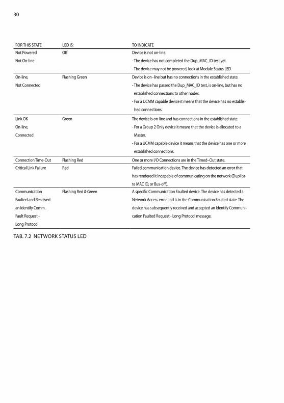
Network Status LEDThis bi-color (green/red) LED indicates the status of the communicationlink. Table 7.2 defines the Network Status LED states. The states shownreflect the network access state machine.
30
fOr ThIS STATE LED IS: TO INDICATE
Not Powered
Not On-line
Off Device is not on-line.
- The device has not completed the Dup_MAC_ID test yet.
- The device may not be powered, look at Module Status LED.
On-line,
Not Connected
flashing Green Device is on–line but has no connections in the established state.
- The device has passed the Dup_MAC_ID test, is on-line, but has no
established connections to other nodes.
- for a UCMM capable device it means that the device has no establis-
hed connections.
Link OK
On-line,
Connected
Green The device is on-line and has connections in the established state.
- for a Group 2 Only device it means that the device is allocated to a
Master.
- for a UCMM capable device it means that the device has one or more
established connections.
Connection Time-Out flashing red One or more I/O Connections are in the Timed–Out state.
Critical Link failure red failed communication device. The device has detected an error that
has rendered it incapable of communicating on the network (Duplica-
te MAC ID, or Bus-off).
Communication
faulted and received
an Identify Comm.
fault request -
Long Protocol
flashing red & Green A specific Communication faulted device. The device has detected a
Network Access error and is in the Communication faulted state. The
device has subsequently received and accepted an Identify Communi-
cation faulted request - Long Protocol message.
TAB. 7.2 NETWOrK STATUS LED

31
8. ASSEMBLy
8.1 ASSEMBLy 101: SETPOINT (OUTPUT fOr POLL)
ByTE TyPE VALUE
0-1 UINT Setpoint master X1 (4096 == 100[%])
2-3 UINT Setpoint master X2 (4096 == 100[%])
… … …
… UINT Setpoint master X ”Slots” (4096 == 100[%])
TAB. 8.1 OUTPUT ASSEMBLy 101
With Thyro-S the setpoint is interpreted as the operating mode.
SETPOINT OPErATING MODE TOTAL SETPOINT
0 to 409 Off 0
410 to 1091 1/5 819
1092 to 1706 1/3 1365
1707 to 3071 1/2 2047
3072 to 4096 ON 4096
TAB. 8.2 INTErPrETATION Of ThE MASTEr SETPOINT fOr Thyro-S

32
8.2 ASSEMBLy 102: SETPOINT, STATE... (INPUT fOr POLL)
8.3 ASSEMBLy 103: ACTUAL VALUE POWEr
ByTE TyPE VALUE POrT
0-1 UINT Total setpoint (4096 == 100[%]) X1
2-3 UINT Thyro-AS error (Table ???)
4-5 UINT Thyro-AS state (Table ???)
6-7 UINT Total setpoint (4096 == 100[%]) X2
…
8-9 UINT Thyro-AS error (Table ???)
10-11 UINT Thyro-AS state (Table ???)
… … …
… UINT Total setpoint (4096 == 100[%]) Xmax
… UINT Thyro-AS error (Table ???)
… UINT Thyro-AS state (Table ???)
TAB. 8.3 INPUT ASSEMBLy 102
ByTE TyPE VALUE POrT
0-3 rEAL Power L1 X1
2 phase4-7 rEAL Power L3
8-11 rEAL Power L1 X2 1 phase
… … … …
… rEAL Power L1 Xmax
3 phase… rEAL Power L2
… rEAL Power L3
TAB. 8.4 INPUT ASSEMBLy 103

33
8.4 ASSEMBLy 104: ACTUAL VALUE VOLTAGE LOAD
ByTE TyPE VALUE POrT
0-3 rEAL Voltage Load L1 X1
2 phase4-7 rEAL Voltage Load L3
8-11 rEAL Voltage Load L1 X2 1 phase
… … … …
… UNIT Voltage Main L1 Xmax
3 phase… UNIT Voltage Main L2
… rEAL Voltage Main L3
TAB. 8.5 INPUT ASSEMBLy 104
8.5 ASSEMBLy 105: ACTUAL VALUE CUrrENT
8.6 ASSEMBLy 106: VOLTAGE MAIN
ByTE TyPE VALUE POrT
0-3 rEAL Current L1 X1
2 phase4-7 rEAL Current L3
8-11 rEAL Current L1 X2 1 phase
… … … …
… rEAL Current L1 Xmax
3 phase… rEAL Current L2
… rEAL Current L3
TAB. 8.6 INPUT ASSEMBLy 105
ByTE TyPE VALUE POrT
0-1 UINT Voltage Main L1 X1
2 phase2-3 UINT Voltage Main L3
4-5 UINT Voltage Main L1 X2 1 phase
… … … …
… UINT Voltage Main L1 Xmax
3 phase… UINT Voltage Main L2
… UINT Voltage Main L3
TAB. 8.7 INPUT ASSEMBLy 106

34
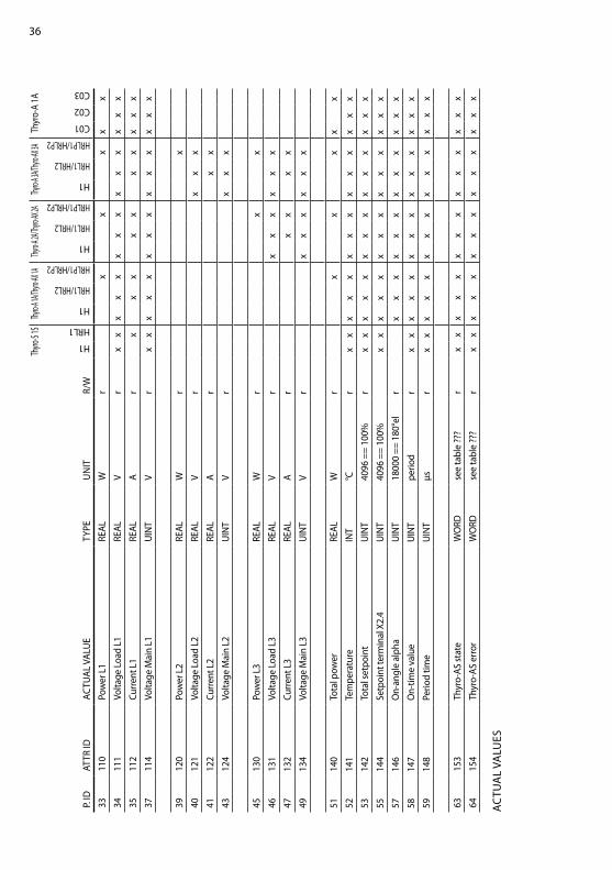
9. VENDOr SPECIfIC ATTrIBUTES
All attributes are listed in the following tables. The attributes are split into 3 objects (0x64-0x66). The epath to a parameter is “20 Class.ID 24 Instance ID 30 Attr.ID” for example the epath to the “Setpoint Master X1” is 20 65 24 01 30 64 (all values hex).
9.1 ATTrIBUTES Of CLASS 0X64This class has just 1 instance.
ATTr ID VALUE TyPE VALUE rANGE r/W
100 X1 configured device type USINT See Table 9.3 r
101 X2 configured device type USINT See Table 9.3 r
102 X3 configured device type USINT See Table 9.3 r
103 X4 configured device type USINT See Table 9.3 r
104 X5 configured device type USINT See Table 9.3 r
105 X6 configured device type USINT See Table 9.3 r
106 X7 configured device type USINT See Table 9.3 r
107 X8 configured device type USINT See Table 9.3 r
TAB. 9.1 CONfIGUrED DEVICE TyPE
ATTr ID VALUE TyPE VALUE rANGE r/W
108 X1 current device type USINT See Table 9.3 r
109 X2 current device type USINT See Table 9.3 r
110 X3 current device type USINT See Table 9.3 r
111 X4 current device type USINT See Table 9.3 r
112 X5 current device type USINT See Table 9.3 r
113 X6 current device type USINT See Table 9.3 r
114 X7 current device type USINT See Table 9.3 r
115 X8 current device type USINT See Table 9.3 r
TAB. 9.2 CUrrENT DEVICE TyPE

35
VALUE TyPE
0 None
4 Thyro-S 1S...h1
5 Thyro-S 1S...hrL1
20 Thyro-A 1A...h1
21 Thyro-A 1A...hrL1/Thyro-AX 1A...hrL2
22 Thyro-A 1A...hrLP1/Thyro-AX 1A...hrLP2
24 Thyro-A 2A...h1
25 Thyro-A 2A...hrL1/Thyro-AX 2A...hrL2
26 Thyro-A 2A...hrLP1/Thyro-AX 2A...hrLP2
28 Thyro-A 3A...h1
29 Thyro-A 3A...hrL1/Thyro-AX 3A...hrL2
30 Thyro-A 3A...hrLP1/Thyro-AX 3A...hrLP2
129 Thyro-A 1A...C01
130 Thyro-A 1A...C02
131 Thyro-A 1A...C03
TAB. 9.3 POWEr CONTrOLLEr TyPE
ATTr ID VALUE TyPE VALUE rANGE COMBO-OPT r/W DEfAULT
130 Actual values average USINT 0…3 Off, 5, 10, 20
values
r/w Off
131 Without IO connection ByTE (Bit 0 Setpoint
master = 0)
(Bit 1 Digital
out = 0)
No, yes
No, yes
r/w
No
No
TAB. 9.4 BUS MODULE SETUP
ATTr ID VALUE TyPE VALUE rANGE COMBO-OPT r/W
120 Digital out ByTE Bit 0 == X1.5
Bit 1 == X2.5
…
Off, On
r/w
TAB. 9.5 DIGITAL OUT
9.2 ATTrIBUTES Of CLASS 0X65This class has 1 instance for every power controller.
ATTr ID SETPOINT TyPE UNIT r/W
100 Setpoint master UINT 4096 == 100[%] r/w
TAB. 9.6 SETPOINTS
36Th
yro-S
1SThy
ro-A 1A
/Thyro
-AX 1A
Thyro-A
2A/Th
yro-AX
2AThy
ro-A 3A
/Thyro
-AX 3A
Thyr
o-A
1A
P. ID
ATTr
IDAC
TUAL
VAL
UE
TyPE
UN
ITr/
W
h1
hrL1
h1
hrL1/hrL2
hrLP1/hrLP2
h1
hrL1/hrL2
hrLP1/hrLP2
h1
hrL1/hrL2
hrLP1/hrLP2
C01
C02
C03
3311
0Po
wer
L1
rEAL
Wr
x
x
xx
x
3411
1Vo
ltage
Loa
d L1
rEAL
Vr
xx
xx
xx
xx
xx
xx
xx
3511
2Cu
rrent
L1
rEAL
Ar
x
x
x
xx
x
xx
xx
3711
4Vo
ltage
Mai
n L1
UIN
TV
rx
xx
xx
xx
xx
xx
xx
x
3912
0Po
wer
L2
rEAL
Wr
x
4012
1Vo
ltage
Loa
d L2
rEAL
Vr
xx
x
4112
2Cu
rrent
L2
rEAL
Ar
x
x
4312
4Vo
ltage
Mai
n L2
UIN
TV
r
x
xx
4513
0Po
wer
L3
rEAL
Wr
x
x
4613
1Vo
ltage
Loa
d L3
rEAL
Vr
x
xx
xx
x
4713
2Cu
rrent
L3
rEAL
Ar
xx
x
x
4913
4Vo
ltage
Mai
n L3
UIN
TV
r
xx
xx
xx
5114
0To
tal p
ower
rEAL
Wr
x
x
xx
x
5214
1Te
mpe
ratu
reIN
T°C
rx
xx
xx
xx
xx
xx
xx
x
5314
2To
tal s
etpo
int
UIN
T40
96 =
= 10
0%r
xx
xx
xx
xx
xx
xx
xx
5514
4Se
tpoi
nt te
rmin
al X
2.4
UIN
T40
96 =
= 10
0%
xx
xx
xx
xx
xx
xx
xx
5714
6O
n-an
gle
alph
aU
INT
1800
0 ==
180
°el
r
x
xx
xx
xx
xx
xx
x
5814
7O
n-tim
e va
lue
UIN
Tpe
riod
rx
xx
xx
xx
xx
xx
xx
x
5914
8Pe
riod
time
UIN
Tµs
rx
xx
xx
xx
xx
xx
xx
x
6315
3Th
yro-
AS st
ate
WO
rDse
e ta
ble
???
rx
xx
xx
xx
xx
xx
xx
x
6415
4Th
yro-
AS e
rror
WO
rDse
e ta
ble
???
rx
xx
xx
xx
xx
xx
xx
x
AC
TUA
L VA
LUES

37
DESCrIPTION Thyro-A/Thyro-AX Thyro-S
Thyro-S, Thyro-A and Thyro-AX BIT LEDs rELAy* LEDs rELAy*
frequency measurement
outside of 47 hz to 63 hz
Bit0 Pulse Inhibit LED flashes
slowly
dropped out Test LED flashes slowly dropped out
SyNC error, no zero crossing within
the gate
Bit1 Pulse Inhibit LED flashes
slowly
dropped out Test LED flashes slowly dropped out
Temperature monitoring triggered Bit2 Load fault LED flashes
slowly
dropped out Load fault flashes slowly dropped out
Load error Bit3 Load fault LED on dropped out Load fault on dropped out
flash values invalid Bit4 Pulse Inhibit LED and Load
fault LED flash fast simulta-
neously
dropped out Test LED and
Load fault LED flash
fast simultaneously
dropped out
Mains Undervoltage
(< AD_P_SPG_MIN)
Bit5 Pulse Inhibit LED,
Load fault LED and
Test-LED on
dropped out Load fault LED and
Test LED on
dropped out
Mains Overvoltage
(> AD_P_SPG_MAX)
Bit6 none energised none energised
Master/Slave error (only with 2A) Bit8 none energised only with Thyro-A/Thyro-AX ---
Undervoltage Limit Bit9 none energised only with Thyro-A/Thyro-AX ---
Overvoltage Limit Bit10 none energised only with Thyro-A/Thyro-AX ---
Undercurrent Limit Bit11 none energised only with Thyro-A/Thyro-AX ---
Overcurrent Limit Bit12 none energised only with Thyro-A/Thyro-AX ---
Low Power Limit Bit13 none energised only with Thyro-A/Thyro-AX ---
high Power Limit Bit14 none energised only with Thyro-A/Thyro-AX ---
Thyro-S, Thyro-A AND Thyro-AX ErrOr

38
* The table only shows the default configuration of the relay function.The relay only exists in the h rL1, h rLP1, h rL2 or h rLP2 device, not in the h1 types.
DESCrIPTION Thyro-A/Thyro-AX Thyro-S
Thyro-S, Thyro-A and Thyro-AX BIT LEDs rELAy* LEDs rELAy*
Pulse blocking active
(bridge X2.1-X2.2open)
Bit0 Pulse Inhibit LED on energised none energised
Mains frequency is 60 hz Bit2 none energised none energised
U limiting active Bit4 Pulse Inhibit LED and Load
fault LED flash slowly
alternately
energised only with Thyro-A/Thyro-AX ---
I limiting active Bit5 Pulse Inhibit LED and Load
fault LED flash slowly
alternately
energised only with Thyro-A/Thyro-AX ---
P limiting active Bit6 Pulse Inhibit LED and Load
fault LED flash slowly
alternately
energised only with Thyro-A/Thyro-AX ---
relay status
(0=relay off/1=relay on)
Bit8 none on/off none on/off
Device disconnected Bit9 --- --- --- ---
Wrong device Bit10 --- --- --- ---
Busmodul aktiv (0=no bus
module/1=bus modul active)
Bit11 none energised none energised
Thyristor short-circuit (Thyro-S) Bit14 only with Thyro-S --- Test LED and
Load fault LED flash slowly
alternately
dropped out
failure in rotating field/phase (only
Thyro 2A or 3A)
Bit15 Pulse Inhibit LED and Test
LED flash slowly simulta-
neously
energised only with Thyro-A/Thyro-AX ---
Thyro-S, Thyro-A AND Thyro-AX STATE
39
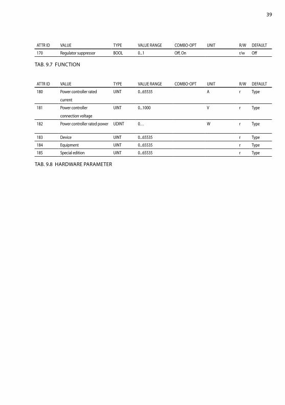
ATTr ID VALUE TyPE VALUE rANGE COMBO-OPT UNIT r/W DEfAULT
170 regulator suppressor BOOL 0...1 Off, On r/w Off
TAB. 9.7 fUNCTION
ATTr ID VALUE TyPE VALUE rANGE COMBO-OPT UNIT r/W DEfAULT
180 Power controller rated
current
UINT 0...65535 A r Type
181 Power controller
connection voltage
UINT 0...1000 V r Type
182 Power controller rated power UDINT 0… W r Type
183 Device UINT 0...65535 r Type
184 Equipment UINT 0...65535 r Type
185 Special edition UINT 0...65535 r Type
TAB. 9.8 hArDWArE PArAMETEr

40Th
yro-S 1
SThy
ro-A 1A/
Thyro-A
X 1AThy
ro-A 2A/
Thyro-A
X 2AThy
ro-A 3A/
Thyro-A
X 3ATh
yro-
A 1A
P. ID
ATTr
IDVA
LUE
TyPE
VALU
E rA
NG
ECO
MBO
-OPT
UN
ITr/
W
h1
hrL1
h1
hrL1/hrL2
hrLP1/hrLP2
h1
hrL1/hrL2
hrLP1/hrLP2
h1
hrL1/hrL2
hrLP1/hrLP2
C01
C02
C03
DEf
AULT
100
100
Ope
ratin
g m
ode
USI
NT
0…3
res.,
TAKT
, VAr
,
qTM
r/
w*
xx
xx
xx
xx
xx
xx
Type
101
101
Load
mod
eBy
TEbi
twise
r/w
xx
x
14
OPE
rATI
NG
MO
DE
Thyro
-S 1S
Thyro-A
1A/Thy
ro-AX 1A
Thyro-A
2A/Thy
ro-AX 2A
Thyro-A
3A/Thy
ro-AX 3A
Thyr
o-A
1A
P. ID
ATTr
IDVA
LUE
TyPE
VALU
E rA
NG
ECO
MBO
-OPT
UN
ITr/
W
h1
hrL1
h1
hrL1/hrL2
hrLP1/hrLP2
h1
hrL1/hrL2
hrLP1/hrLP2
h1
hrL1/hrL2
hrLP1/hrLP2
C01
C02
C03
DEf
AULT
110
110
Phas
e an
gle
of th
e
1st h
alf-w
ave
USI
NT
0…18
0
°el
r/w
*
x
xx
xx
xx
xx
xx
Type
111
111
Soft-
start
time (
setti
ng)
UIN
T0…
100
pe
riod
r/w
*
x
xx
xx
xx
xx
xx
x6
112
112
Soft-
down
time (
setti
ng)
UIN
T0…
100
pe
riod
r/w
xx
xx
xx
xx
xx
xx
6
113
113
Cycl
e pe
riod
UIN
T0…
1000
pe
riod
r/w
*x
xx
xx
xx
xx
xx
x
x50
114
114
Max
. cyc
le o
n-tim
eU
INT
1…10
00
perio
dr/
w
x
xx
xx
xx
xx
x
x50
115
115
Min
. cyc
le o
n-tim
eU
INT
0…10
00
perio
dr/
w
x
xx
xx
xx
xx
x
x0
116
116
Min
. pau
seU
SIN
T0…
10
perio
dr/
w*
xx
xx
xx
xx
xx
x
311
711
7Sy
ncro
nous
cyc
le
addr
ess
UIN
T0.
..655
35
perio
d/2
r/w
xx
xx
xx
xx
xx
x
100
TIM
ES
9.3 ATTrIBUTES Of CLASS 0X66This class has 1 instance for every power controller.

41
Thyro
-S 1S
Thyro-A
1A/Thy
ro-AX 1A
Thyro-A
2A/Thy
ro-AX 2A
Thyro-A
3A/Thy
ro-AX 3A
Thyr
o-A
1A
P. ID
ATTr
IDVA
LUE
TyPE
VALU
E rA
NG
ECO
MBO
-OPT
UN
ITr/
W
h1
hrL1
h1
hrL1/hrL2
hrLP1/hrLP2
h1
hrL1/hrL2
hrLP1/hrLP2
h1
hrL1/hrL2
hrLP1/hrLP2
C01
C02
C03
DEf
AULT
120
120
regu
latio
nU
SIN
T0…
8U
load
^2,
Ulo
ad e
ff,
Iload
^2,
Iload
eff,
res.
real
pow
er
res.
res.
With
out
regu
latio
n
r/w
*
x
xx
xx
xx
xx
xx
xTy
pe
121
121
PID
-regu
lato
r, I-p
art
UIN
T0.
..655
35,
0 =
Off
r/
w
x
xx
xx
xx
xx
xx
xTy
pe
122
122
PID
-regu
lato
r, P-
part
UIN
T0.
..655
35,
0 =
Off
r/
w
x
xx
xx
xx
xx
xx
xTy
pe
123
123
PID
-regu
lato
r,
coun
ter P
-par
t
UIN
T0.
..655
35
r/w
xx
xx
xx
xx
xx
xx
Type
CON
TrO
LS

42Th
yro-S 1
SThy
ro-A 1A/
Thyro-A
X 1AThy
ro-A 2A/
Thyro-A
X 2AThy
ro-A 3A/
Thyro-A
X 3ATh
yro-
A 1A
P. ID
ATTr
IDVA
LUE
TyPE
VALU
E rA
NG
ECO
MBO
-OPT
UN
ITr/
W
h1
hrL1
h1
hrL1/hrL2
hrLP1/hrLP2
h1
hrL1/hrL2
hrLP1/hrLP2
h1
hrL1/hrL2
hrLP1/hrLP2
C01
C02
C03
DEf
AULT
130
130
Max. r
.m.s.
volta
ge se
tpoint
UIN
T0.
..655
35
Vr/
w*
xx
xx
xx
xx
xx
xx
Type
131
131
Max. r
.m.s.
curre
nt set
point
UIN
T0.
..655
35
0,1
Ar/
w*
x
x
xx
x
xx
xx
Type
132
132
Max. p
ower
setpo
intUD
INT
0…
Wr/
w*
x
x
xx
x
Type
133
133
front
pulse
limit p
ositio
nU
SIN
T0.
..180
°e
lr/
w
x
xx
x
xx
xx
x18
0°el
134
134
Back
pulse
limit p
ositio
nU
SIN
T0.
..180
°e
lr/
w
x
xx
x
xx
xx
x0°
el
135
135
factor
peak
curren
t limita
tion
UIN
T0…
4096
r/w
xx
xx
xx
xx
xx
xx
Type
LIM
IT
Thyro
-S 1S
Thyro-A
1A/Thy
ro-AX 1A
Thyro-A
2A/Thy
ro-AX 2A
Thyro-A
3A/Thy
ro-AX 3A
Thyr
o-A
1A
P. ID
ATTr
IDVA
LUE
TyPE
VALU
E rA
NG
ECO
MBO
-OPT
UN
ITr/
W
h1
hrL1
h1
hrL1/hrL2
hrLP1/hrLP2
h1
hrL1/hrL2
hrLP1/hrLP2
h1
hrL1/hrL2
hrLP1/hrLP2
C01
C02
C03
DEf
AULT
140
140
Setp
oint
sele
ctU
SIN
T0…
3 X
2.4,
Bit1
Mas
ter
r
xx
xx
xx
xx
xx
xx
xx
Term
inal
X2.4
141
141
Contr
ol sta
rt term
inal X
2.4U
INT
0…40
96
20/40
96 m
Ar/
w*
xx
xx
xx
xx
xx
xx
0 m
A
142
142
Cont
rol en
d term
inal X
2.4U
INT
0…40
96
20/40
96 m
Ar/
w
x
xx
xx
xx
xx
xx
x20
mA
CON
TrO
L Ch
ArA
CTE
rIST
IC

43
Thyro
-S 1S
Thyro-A
1A/Thy
ro-AX 1A
Thyro-A
2A/Thy
ro-AX 2A
Thyro-A
3A/Thy
ro-AX 3A
Thyr
o-A
1A
P. ID
ATTr
IDVA
LUE
TyPE
VALU
E rA
NG
ECO
MBO
-OPT
UN
ITr/
W
h1
hrL1
h1
hrL1/hrL2
hrLP1/hrLP2
h1
hrL1/hrL2
hrLP1/hrLP2
h1
hrL1/hrL2
hrLP1/hrLP2
C01
C02
C03
DEf
AULT
150
150
Aver
agin
gU
INT
0…65
535
r/w
x
x
xx
x
xx
xx
100
151
151
Confi
gura
tion
regi
s-
ter a
nalo
g ou
tput
1
USI
NT
0…10
0-5
rese
rved
,
Ueff
, Ieff,
Tota
l pow
er,
Setp
oint
,
Ueff
mai
n
r/
w
xx
x
x
xx
xx
xU
eff
152
152
Offs
et o
utpu
t 1U
INT
0…40
96
20/40
96 m
Ar/
w*
x
x
xx
x
xx
xx
0 m
A15
315
3Sc
alin
g fa
ctor
outp
ut 1
UIN
T0…
4096
1/
819
r/w
*
xx
x
x
xx
xx
x1
154
154
Confi
gura
tion
regi
s-
ter a
nalo
g ou
tput
2
USI
NT
0…10
0-5
rese
rved
,
Ueff
, Ieff,
Tota
l pow
er,
Setp
oint
,
Ueff
mai
n
r/w
x
x
Ieff
155
155
Offs
et o
utpu
t 2U
INT
0…40
96
20/40
96 m
Ar/
w
x
x0
mA
156
156
Scal
ing
fact
or
outp
ut 2
UIN
T0…
4096
1/
819
r/w
x
x
1
157
157
Confi
gura
tion
regi
s-
ter a
nalo
g ou
tput
3
USI
NT
0…10
0-5
rese
rved
,
Ueff
, Ieff,
Tota
l pow
er,
Setp
oint
,
Ueff
mai
n
r/
w
x
xTo
tal
pow
er
158
158
Offs
et o
utpu
t 3U
INT
0…40
96
20/40
96 m
Ar/
w
x
x0
mA
159
159
Scal
ing
fact
or
outp
ut 3
UIN
T0…
4096
1/
819
r/w
x
x
1
AN
ALO
G O
UTP
UTS

44Th
yro-S 1
SThy
ro-A 1A/
Thyro-A
X 1AThy
ro-A 2A/
Thyro-A
X 2AThy
ro-A 3A/
Thyro-A
X 3ATh
yro-
A 1A
P. ID
ATTr
IDVA
LUE
TyPE
VALU
E rA
NG
ECO
MBO
-OPT
UN
ITr/
W
h1
hrL1
h1
hrL1/hrL2
hrLP1/hrLP2
h1
hrL1/hrL2
hrLP1/hrLP2
h1
hrL1/hrL2
hrLP1/hrLP2
C01
C02
C03
DEf
AULT
170
170
Main
s vol
tage
mon
itorin
g m
inim
um
UIN
T0.
..100
0
Vr/
wx
xx
xx
xx
xx
xx
xx
x32
0
171
171
Mai
ns v
olta
ge
mon
itorin
g
max
imum
UIN
T0.
..100
0
Vr/
wx
xx
xx
xx
xx
xx
xx
x48
0
172
172
Und
ercu
rrent
mon
itorin
g
BOO
L0.
..1O
ff, O
n
r/w
*
x
xx
x
x
xx
xx
xO
ff
173
173
Und
ercu
rrent
mon
itorin
g va
lue
USI
NT
0...4
505
10
0/
4096
%
r/w
*
x
xx
x
x
xx
xx
x0
174
174
Out
put v
olta
ge
mon
itorin
g m
in.
UIN
T0.
..655
35,
0 =
Off
Vr/
w
x
xx
xx
xx
xx
x
xO
ff
175
175
Out
put v
olta
ge
mon
itorin
g m
ax.
UIN
T0…
6553
5,
max
= O
ff
V
r/w
xx
xx
xx
xx
xx
x
Off
176
176
Out
put c
urre
nt
mon
itorin
g m
in.
UIN
T0.
..655
35,
0 =
Off
0.
1 A
r/w
x
x
xx
x
xx
x
Off
177
177
Out
put c
urre
nt
mon
itorin
g m
ax.
UIN
T0…
6553
5,
max
= O
ff
0.1
Ar/
w
xx
x
x
xx
x
xO
ff
178
178
Out
put p
ower
mon
itorin
g m
in,.
UDIN
T0.
..655
35,
0 =
Off
W
r/w
x
x
xx
x
Off
179
179
Out
put p
ower
mon
itorin
g m
ax.
UDIN
T0…
6553
5,
max
= O
ff
W
r/w
x
x
xx
x
Off
MO
NIT
OrI
NG

45
Thyro
-S 1S
Thyro-A
1A/Thy
ro-AX 1A
Thyro-A
2A/Thy
ro-AX 2A
Thyro-A
3A/Thy
ro-AX 3A
Thyr
o-A
1A
P. ID
ATTr
IDVA
LUE
TyPE
VALU
E rA
NG
ECO
MBO
-OPT
UN
ITr/
W
h1
hrL1
h1
hrL1/hrL2
hrLP1/hrLP2
h1
hrL1/hrL2
hrLP1/hrLP2
h1
hrL1/hrL2
hrLP1/hrLP2
C01
C02
C03
DEf
AULT
190
190
rela
y K1
con
fig 1
WOr
Dbi
twise
r / w
x
x
xx
x
xx
xx
447
191
191
rela
y K1
con
fig 2
WOr
Dbi
twise
r / w
x
x
xx
x
xx
xx
3276
819
219
2Pu
lse sw
itch-
off o
n
erro
r reg
ister
WOr
Dbi
twise
r / w
xx
xx
xx
xx
xx
xx
307
193
193
Vers
ion
year
UIN
T0…
6553
5
r
xx
xx
xx
xx
xx
xx
xx
Type
194
194
Vers
ion
mon
thU
SIN
T1.
..12
rx
xx
xx
xx
xx
xx
xx
xTy
pe
195
195
Vers
ion
day
USI
NT
1...3
1
r
xx
xx
xx
xx
xx
xx
xx
Type
MIS
CELL
AN
EOU
S
* In
”Th
yro-
Tool
mod
e” (s
witc
h S1
.3-5
”On”
) the
par
amet
ers
mar
ked
with
* a
re n
ot p
rese
t by
the
switc
hes
and
potis
, ins
tead
,th
e st
ored
val
ues
are
used
.
With
som
e co
ntro
ller t
ypes
not
all
sett
ings
are
pos
sibl
e.
S
ettin
g de
pend
s on
type
vol
tage
, typ
e cu
rren
t and
type
out
put.
Aft
er s
ettin
g to
def
ault,
ple
ase
chec
k!

46
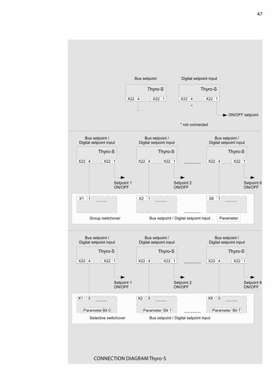
10. CONNECTION DIAGrAMS
Thyro-A .. 1
Thyro-AX .. 2
47
CONNECTION DIAGrAM Thyro-S

48
CONNECTION DIAGrAM Thyro-A/Thyro-AX

49
11. hELP IN ThE EVENT Of PrOBLEMS
The devices delivered correspond to quality standard ISO 9001. Shouldyou experience any malfunctions or other problems, please contact our Ad-vanced Energy team for assistance (see chapter CONTACT INfOrMATION).
We have listed a few tips below for troubleshooting:LED Power is off> Check 24VDC power supply at X11LED fault is flashing> Check connection between all power controllers and bus modules.> Check power supply for all power controllers.LED Module Status is flashing red> Check 24VDC power supply at X20LED Module Status is red> hardware defectLED Network Status is flashing green (baud rate detection)> Check DeviceNet connection X20> Check DeviceNet scanner is running

50
12. TEChNICAL DATA
BusmodulVoltage range 20-28 V DCInrush current (28V) 2.8 A for 10 msOperation current 150 mA maxAmbient temperature Max. 65 °C
DeviceNetAddress range 0-63 (63-99 => 63)Communication speed 125, 250 and 500 kBaudConnector Open-style connector
DeviceNet Supply Voltage range 11-25 V DC Inrush current (25 V) 0.1 A Operation current 5 mA max
features Auto baud detection Module Status LED Network Status LED Complete control of all Thyro-S, Thyro-A and Thyro-AX attributes Mounting on DIN rail Up to 8 Advanced Energy power controllers of the Thyro-S, Thyro-A and
Thyro-AX series of types ...h1, ...h rL1 , ...h rLP1, ...h rL2 and ...h rLP2.
51
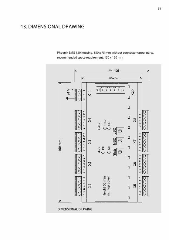
13. DIMENSIONAL DrAWING
Phoenix EMG 150 housing, 150 x 75 mm without connector upper parts, recommended space requirement: 150 x 150 mm
DIMENSIONAL DrAWING
Hei
ght 5
5 m
m
incl
. top
cov
er

52
14. ACCESSOrIES AND OPTIONS
Shielded cables with preassembled bus module connectors are available.A cable set consists of 4 connection cables of the same length to connect 4 power controllers.Order no. 2000 000 848 Bus module connection cable for 4 powercontrollers, 2.5 mOrder no. 2000 000 849 Bus module connection cable for 4 powercontrollers, 1.5 m
15. APPrOVALS AND CONfOrMITy
- Data transmission in acc. with ISO 11898- quality standard in acc. with DIN EN ISO 9001- CE conformity- Low voltage directive 73/23 EEC- EMC directive 89/336 EEC; 92/31 EEC- Marking directive 93/68 EEC
DIrECTIVESThe CE mark on the device confirms compliance with the EC directives72/23 EEC for low voltage and 89/339 EEC for electromagnetic compatibility if the instructions on installation and start-up described in the operating instructions are followed.
53
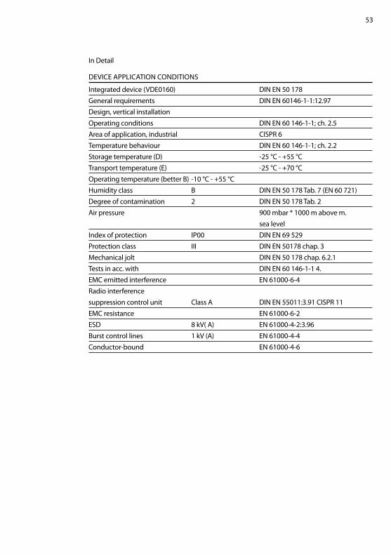
In Detail
DEVICE APPLICATION CONDITIONS
Integrated device (VDE0160) DIN EN 50 178General requirements DIN EN 60146-1-1:12.97Design, vertical installationOperating conditions DIN EN 60 146-1-1; ch. 2.5Area of application, industrial CISPr 6Temperature behaviour DIN EN 60 146-1-1; ch. 2.2Storage temperature (D) -25 °C - +55 °CTransport temperature (E) -25 °C - +70 °COperating temperature (better B) -10 °C - +55 °Chumidity class B DIN EN 50 178 Tab. 7 (EN 60 721)Degree of contamination 2 DIN EN 50 178 Tab. 2Air pressure 900 mbar * 1000 m above m. sea levelIndex of protection IP00 DIN EN 69 529Protection class III DIN EN 50178 chap. 3Mechanical jolt DIN EN 50 178 chap. 6.2.1Tests in acc. with DIN EN 60 146-1-1 4.EMC emitted interference EN 61000-6-4radio interference suppression control unit Class A DIN EN 55011:3.91 CISPr 11EMC resistance EN 61000-6-2ESD 8 kV( A) EN 61000-4-2:3.96Burst control lines 1 kV (A) EN 61000-4-4Conductor-bound EN 61000-4-6

54
World headquarters
1625 Sharp Point Drive
fort Collins, CO 80525 USA
970.221.4670 Main
970.221.5583 fax
www.advanced-energy.com
Specifications are subject to change without notice.
© 2014 Advanced Energy Industries, Inc. All rights reserved. Advanced Energy® and Thyro-S™, Thyro-A™, Thyro-AX™ are trademarks of Advanced Energy Industries, Inc.

55