BUSINESS PROPOSAL: Wireless Biosignal Monitor
43
BUSINESS PROPOSAL: Wireless Biosignal Monitor Tee Pamon Hala Mostafa Matt Mancuso Simon Rubinsky Bridget Matikainen
Transcript of BUSINESS PROPOSAL: Wireless Biosignal Monitor

BUSINESS PROPOSAL:
Wireless Biosignal Monitor
Tee Pamon
Hala Mostafa
Matt Mancuso
Simon Rubinsky
Bridget Matikainen

Introduction to ECG (Electrocardiogram):
An electrocardiogram (ECG) is one of the simplest and fastest procedures used to
evaluate the heart (1). Electrocardiographs record the information in a non-invasively via
skin electrodes. A physician is then able to see real-time images of electrical activity that
is going on in the heart. By examining the waves, a physician can detect abnormalities, as
well as previous damage due to heart disease, high blood pressure, or birth defects. In
addition to this, previous heart attacks can also be seen on the pattern and constant
follow-ups can show whether heart muscles are healing. The ECG can also detect
whether specific drugs are effective on the heart and if an implanted pacemaker is
working correctly (2).
Market Needs:
An ECG device is an important life saving tool that can both diagnose and
monitor heart conditions for patients. Each year, millions of people in the U.S. have heart
attacks, half of which are fatal. Of those, 50% never even reach the hospital. Sadly, many
of these patients’ previous medical histories implicated high risks for heart attacks and a
wireless ECG device could have been utilized to alert emergency medical services (EMS)
and possibly save thousands of lives a year (3).
Recent developments have shown that portable ECGs can actively record
patients’ heart signals and could act as personal health assistants (4). These wireless

devices can be used for patient follow-ups after surviving cardiac arrest or ventricular
tachycardia, as well as acting as diagnostic tools. Billions of these dollars are spent on
routine doctor visits, lab tests, and monitoring procedures. A wireless ECG device could
lower medical bills for individuals as well as decrease the United States’ health
expenditures (5).
Wireless technology will become necessary to provide sufficient healthcare to the
increasing number of elderly. It has been calculated that number of adults between 65-84
years of age is expected to double from 35 million to 70 million by 2025. If almost one-
third of U.S. adults, with full time jobs, are serving as informal caregivers- mostly to
elderly patients, it is necessary to build remote healthcare monitoring systems (6).
Wireless ECGs, and other bio-monitoring systems, can provide automatic health
services continuously, accurately, and cost. Such apparatuses can effectively monitor
patient’s medication intake or ECG signal. A wireless ECG product excludes expensive
cellular networks and wireless Local Area Networks (LANs). Wireless ECGs can create a
low-cost and short distance healthcare system (6).
These types of wireless devices can provide completing monitoring of elderly in
nursing homes. Wireless ECGs allow for the mobility of the senior citizens, including
independence. Independent living quarters will not constantly require the presence of
nurses. Caretakers could have all the vital information sent to them and displayed on a
central computer system.
This wireless technology can finally overcome the major hindrance of other
devices, financial costs. Hospitals pay an average of $4,500 for an ECG machine,
monitoring equipment and analyzing software (7). Portable ECG devices used by
practitioners and small clinics can run anywhere from $1000-$4000 per machine (8).
Less capital and time can be concentrated into a portable device that will be more widely
utilized (3). Digital filtering is of better quality, more accurate and faster (9).
Wireless ECGs and other bio-monitoring systems can also provide the patients
with mobility and constant observation throughout the hospital. Doctors and nurses can
witness real-time data collection without interrupting patients’ movements or privacy.
Customer Needs:
The necessity of a wireless medical monitoring device, such as an ECG, is evident
when analyzing the consumer’s standards. Since the customer base of such a purchase is
vast, scalability is essential to provide each entity with what is needed, and no more. A
research scientist doing a cardiac study could purchase a single wireless ECG. An
individual apparatus is bought, without any complications. However, a nursing home and
a hospital would require buying several machines, as well as any software preventing
signal interference. This device allows the implementation of an entire network, or just a
single device.
Another focus of a wireless bio-signal monitor would be the modular aspect. If
running an entire system, customers’ will require the ability to view and observe more
than one ECG signal at a time. Hospitals and nursing homes will have several hundred
patients present at once, and due to safety and privacy, their medical information must
remain separate.
The device should be able to send out an alert, should the patient being monitored
exhibit signs of a medical emergency. Using a text message alert accessible through the
internet, this instantaneous alert could significantly enhance emergency care provider
response time.
Another customer need for such systems is the mobility that they will allow.
Wireless medical devices will promote more active patients while allowing more medical
attention. Elderly in homes and patients, who should not be confined to hospital beds,
should remain dynamic without eliminating healthcare. People being safely monitored
from rooms away will have their privacy as well as their independence returned.
To allow for such freedom of motion, this type of device will require a battery. As
an energy source for delivering wireless information, the battery must have enough
power to send various signals from different ranges. Wavelengths and frequencies must
travel from room to room, through walls, people and even other signals. The battery must
be strong enough to broadcast a clear, accurate signal for the receiver to read.
The battery must also have a lifespan long enough to prevent recharging
constantly. The battery should be able to go days, definitely hours, without having to be
changed.
Technical Specifications:
Modular Design
Perhaps the most novel of the technical specifications associated with our wireless
biosignal monitor is its modular design. This specification carries the highest weight
when compared to other technical specifications. This modularity applies to the biosignal
monitor in two ways; a monitoring system in a hospital setting that receives signals from
multiple patients, as well as a system that can receive multiple biological signals from a
single patient. Both of these aspects are represented as customer needs, and their
essentiality has already been discussed. The novelty of our design lies in the modularity
of the biosignal monitor; thus, a technically modular model is pertinent.
The device requires programming in two respects; the reader computer designated
as receiving all signals, and the main body of the wearable-end of the device. These two
areas must be programmed adequately in order to provide for the acquisition and
conditioning of multiple signals synonymously, as well as for the initial collection of
various biosignals from a singular patient, respectively.
Secure Communication
As with all medical information, security is absolutely germane. Digital
encryption or scrambled frequency transmission could be used to protect a patient’s
signal information from being hacked or altered (10). The wireless transmission of a
biological signal must be protected against outside attainment for both the privacy and
ease of the patient, as well as the maintenance of the integrity of the received
information.
Real-Time Data Acquisition
A biosingal monitor, such as an ECG, can be used for diagnostic or supervisory
medicine (11). Our proposed device will focus primarily on the supervision or monitoring
of a patient. Therefore it is necessary to have real-time data acquisition and observation,
so as to ensure an immediate response in the event of a medical emergency.
This is achieved through frequent signal transmission of data from the patient’s
wearable device to the reader. A comparable medium should be reached as far as the rate
of signal transmission – data should be transmitted often enough for a practically real-
time response of healthcare professionals, while infrequent enough to warrant preserving
battery life.
Multi-Channeled Receiver
Previously mentioned was the intended ability of our device to monitor multiple
patients simultaneously. This requires the reader, that is, the computer receiving the
signals, to have multiple channels that can each receive a different frequency signal.
Power Source
Though easy to overlook amongst flashier aspects of technology, the source of

electricity that will provide power to the device the patient wears is significant; it will
determine the run-time of the device, and how often the power source needs to be
replaced or recharged. As mentioned above, the rate at which data is transmitted to the
receiving computer will be a function of (and trade-off between) battery life and the
necessity to closely imitate real-time data acquisition.
Computer Software
The novelty of this proposed biosignal monitoring system demands new software
written to collaborate with the reader computer, as well as additional programming of the
microcontroller that will be used to transmit sensory data wirelessly from the device.
Durability
This technical specification applies to the mobile device worn by the patient. The
casing in which the device (excluding any electrodes or sensors) is placed needs to be
resistant to potential damage. For example, the act of the patient wearing the device
makes the device susceptible to both physical and water damage; thus both of those
factors need to be taken into account when making a prototype of the device casing.
Additionally, the electrodes or sensors used need to be resilient so as to accurately record
for the duration of the monitoring.
Quality Function Deployment (QFD):
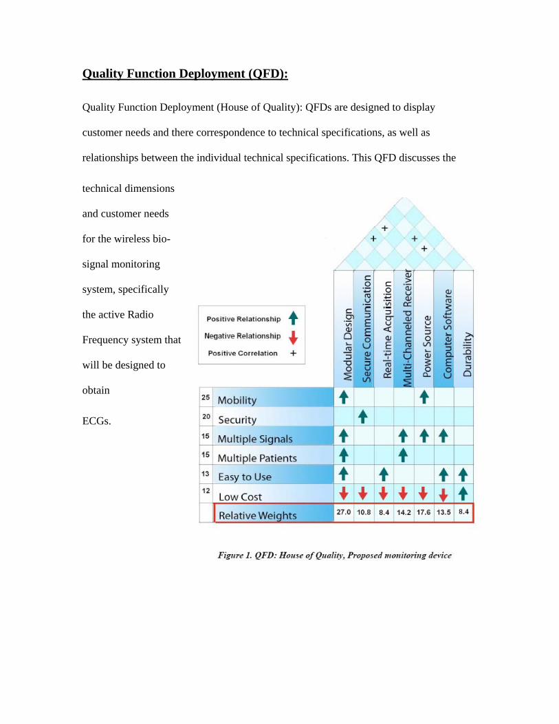
Quality Function Deployment (House of Quality): QFDs are designed to display
customer needs and there correspondence to technical specifications, as well as
relationships between the individual technical specifications. This QFD discusses the
technical dimensions
and customer needs
for the wireless bio-
signal monitoring
system, specifically
the active Radio
Frequency system t
will be designed to
obtain
hat
ECGs.

DESIGN HISTORY:
Wireless Biosignal Monitor

Design Alternatives for Wireless Biosignal Monitoring:
Our designs to achieve wireless transmission of biological signals can be divided
into four different categories: active, semi-active, passive, and semi-passive systems.
Active wireless systems require the constant use of power source to continuously receive
and transmit a signal; usually a battery provides the power. Semi-active system function
similar to active systems in that power is needed to both acquire and transmit the signal.
However, in semi-active systems, the signal is transmitted in pulses rather than
continuously. Although transmitting the signal only at specific intervals of time means
that data is not fully real time (during the period in which the system does not transmit a
signal), this method of signal transmission uses significantly less battery power than
active systems.
Passive wireless systems, unlike the active and semi-active systems, do not
require a power source to receive or transmit signals. RF induction generates the power
needed to drive the circuit. Semi-passive wireless systems are an intermediate between
the active and passive wireless systems in that a power source is needed, however, the
battery power is used only to amplify the signal; no power is used during signal
transmission. Therefore, in semi-passive wireless systems, battery power is used less
often and requires much less power than active and semi-active systems (12).

Both passive and semi-passive forms of wireless technology use radio-frequency
induction to transfer energy. This supplying of energy without a power source, in both
passive and semi-passive technology, can be explained by Faraday’s law, which states
that an emf, or voltage, will be induced if there is a change in the magnetic field strength
in the environment. In RF induction, there are two coils that are inductively coupled to
one another. An alternating current is passed through the first coil which creates a
changing magnetic field; this change in the magnetic field induces a voltage in the second
coil (13).
The occasional use of battery power in the semi-passive system gives it an
important advantage over passive technology. Using battery power to amplify the
incoming signal gives the semi-passive system increased sensitivity. Since biosignals are
relatively low in magnitude, increased sensitivity is needed to acquire an accurate
measurement of these signals (14). The increased sensitivity achieved by the addition of
battery power in semi-passive systems however, is significantly lower than that achieved
in active and semi-active systems.
Each of the four methods of establishing a wireless connection have advantages
and disadvantages; the active and semi-active systems are more power intensive, but have
a much farther range. Passive and semi-passive systems are cheaper and use much less
power, however, they sacrifice a significant amount of range in transmission. To better
understand which of these methods should be pursued for our medical device, we will

explore the application of each of these systems to biosignal monitoring. However, before
we go over the four alternatives for establishing a wireless connection, we will first
consider two different design forms of our device.
Design Form #1: Modular Box with Wireless Capabilities
Our first design form of the device consists of surface electrodes (sensors)
connected to a box with a modular design, which gives the user the ability to collect a
variety of biosignals (i.e. ECG, EEG, EMG) without making any changes to the circuitry
of the box. If for example, we were collecting electrocardiogram signals of a patient
(connected to ECG electrodes) with our modular box, and were suddenly interested in the
EMG measurements of the same patient, we could easily make a transition from ECG
measurements to EMG measurements by disconnecting the ECG electrodes, replacing
them with EMG surface electrodes. In addition to making the switching between
biosignals easy, the modular design of the box would allow us to acquire multiple
biosignals at the same time.
The box will have multiple analog inputs in which the wires of the surface
electrodes can be connected to the device. Also, it will have antennas, to receive signals
from the electrodes and to transmit these signals to a master computer.
The master computer center will be connected to the modular box via a wireless
system (the various alternatives in which this wireless connection can be established will

be discussed in our design alternatives section). Also the mater computer will have a
graphic user interface that plots the biosignals in real-time.
Design Form #2: Wireless Electrode
Unlike the modular box, in the second design form, each electrode is a separate
module and sends its own signal to the receiver. Every electrode will have its own
antenna that can receive and transmit a signal and a relatively small sized battery to
power the system. Like the modular box design, the wireless electrode will have the
ability to acquire a variety of biosignals (not limited to ECG signals).
A wireless connection will be established between each of the individual
electrodes and the master computer (again, the various systems used to create the wireless
connection will be discussed in the design alternatives). The graphic user interface (at the
master computing center) will perform the necessary operations to obtain a single
waveform from the multiple incoming electrode signals that are relayed to the master
computer. The following describes four different ways in which we will establish the
wireless connection for our device:
Design Alternatives
Design Alternative #1: Active Wireless Biosignal Monitoring
Our first design alternative uses an active system to wirelessly transmit biosignals.

Surface electrodes will be placed on the patient (to collect, for example, ECG, EMG, or
EEG). The signal acquired from the electrodes will then be relayed to a microcontroller,
located either on the modular box (design form #1) or on the electrode (design form #2).
The microcontroller will then convert the analog biosignal to a digital signal, and this
digital signal will be transmitted (through an antenna) to the master computer. The
microcontroller will acquire and transmit the biosignal continuously, using battery power
during the entire duration of biosignal monitoring. This alternative will produce the most
accurate signal because it will acquire the greatest amount of data points within a given
period of time, as compared to the other wireless systems. However, due to the
continuous acquisition of the signal, the active system will dissipate the battery power at
the fastest rate.
Design Alternative #2: Semi-Active Wireless Biosignal Monitoring
The semi-active method of biosignal monitoring will follow the same design as
the active system (electrodes relaying the signal to a microcontroller) except the signal
from the microcontroller will be transmitted to the master computer in pulses rather than
continuously. Transmitting the signal in intervals saves a significant amount of battery
power but does add a time lapse from data collection to analysis. The semi-active system
is a feasible solution for wireless biosignal monitoring if the idle time is kept brief, to
maintain a signal that is accurate enough for doctors/researchers to perform analysis on
the resulting waveform.
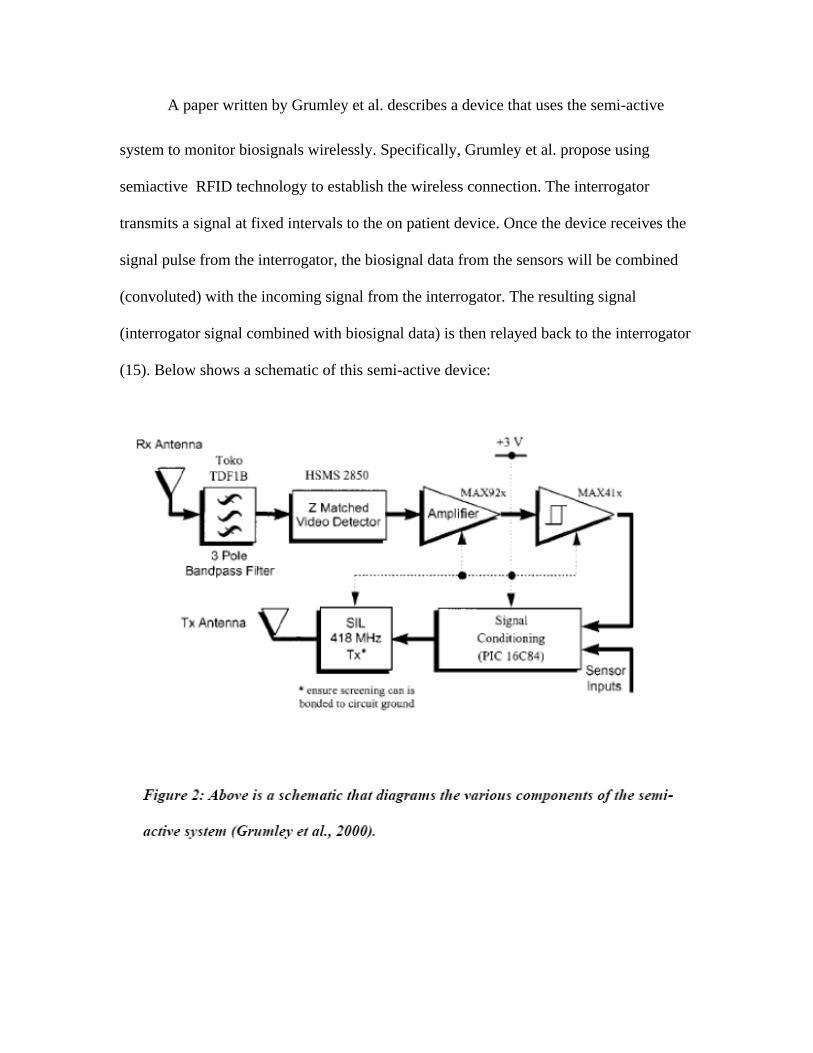
A paper written by Grumley et al. describes a device that uses the semi-active
system to monitor biosignals wirelessly. Specifically, Grumley et al. propose using
semiactive RFID technology to establish the wireless connection. The interrogator
transmits a signal at fixed intervals to the on patient device. Once the device receives the
signal pulse from the interrogator, the biosignal data from the sensors will be combined
(convoluted) with the incoming signal from the interrogator. The resulting signal
(interrogator signal combined with biosignal data) is then relayed back to the interrogator
(15). Below shows a schematic of this semi-active device:
Once the interrogator receives the convoluted signal, it will relay the signal to the
master-computing center, where deconvolution can be performed to extract the biosignal
data. With the biosignal data isolated, the computing center will plot a waveform.
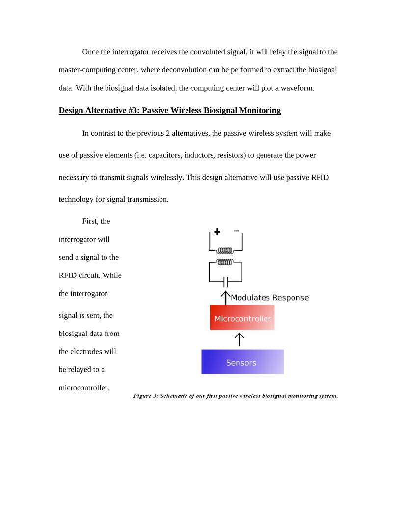
Design Alternative #3: Passive Wireless Biosignal Monitoring
In contrast to the previous 2 alternatives, the passive wireless system will make
use of passive elements (i.e. capacitors, inductors, resistors) to generate the power
necessary to transmit signals wirelessly. This design alternative will use passive RFID
technology for signal transmission.
First, the
interrogator will
send a signal to the
RFID circuit. While
the interrogator
signal is sent, the
biosignal data from
the electrodes will
be relayed to a
microcontroller.
The response of the microcontroller will not be to actively transmit the signal (as
in active and semi-active systems). Instead, it will change the properties of the passive
elements in the circuit in to send a signal back to the interrogator. In our specific design
alternative, the microcontroller changes the capacitance of the RFID circuit, which is
sensed by the interrogator (the upper circuit loop) (Figure 3). From the change in
capacitance, the master-computing center will then perform the necessary calculations to
obtain a waveform of the biosignal being measured.
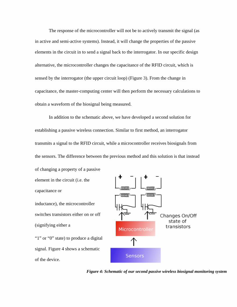
In addition to the schematic above, we have developed a second solution for
establishing a passive wireless connection. Similar to first method, an interrogator
transmits a signal to the RFID circuit, while a microcontroller receives biosignals from
the sensors. The difference between the previous method and this solution is that instead
of changing a property of a passive
element in the circuit (i.e. the
capacitance or
inductance), the microcontroller
switches transistors either on or off
(signifying either a
“1” or “0” state) to produce a digital
signal. Figure 4 shows a schematic
of the device.
Figure 4: Schematic of our second passive wireless biosignal monitoring system

In our schematic, we depicted two interrogator and RFID circuit pairs to show
that the microcontroller can be used to switch multiple transistors on and off to transmit
multiple signals simultaneously.
Although the use of a passive wireless system seems highly promising due to its
ability to transmit signals without the use of power, the accuracy of the resulting signal
would be too low to be of significant value to doctors/researchers. Since biosignals are
low in magnitude, the use of an inaccurate passive system would not be the best solution.
Design Alternative 4: Semi-passive Wireless Biosignal Monitoring:
Our semi-passive wireless alternative is an extension of our passive design in that
battery power and an operational amplifier are added to the device, for the sole purpose
of signal amplification. Therefore, the two solutions discussed in the passive wireless
alternative section can be applied to semi-passive wireless technology. Just as in the
passive wireless system, battery power will not be used to transmit the signal back to the
master computer; the signal will be transmitted either through the modification of the
capacitance of the RFID circuit, or the switching of transistors. As discussed earlier, the
addition of the Op-Amp allows for increased sensitivity, resulting in more accurate
biosignal measurements compared to the passive systems.
Even though the battery powered signal amplification increases accuracy, a
problem of the passive system alternative, it still results in a signal that is not accurate
enough for use in the hospital setting.

Evaluation of Alternatives Based of Range and Power Consumption:
We evaluated four different active RF technology options (active RF technology,
semiactive RF technology, passive RFID, and semi-passive RFID) and chose the most
cost-effective and reliable solution. Our customer needs indicated that mobility is one of
the most important traits of our device. Technically speaking, mobility is determined
mostly by the duration the device lasts without being plugged in and the range of the
device.
In terms of range, RF technology out performs RFID technology with RFID
having a range of 30 feet and RF technologies having a range of 1000 feet. Here RF is a
clear winner, with both active and semi-active systems having the same range.
The main power consumption is due to the Microcontroller and Transmitter. The
other pieces use significantly less, and will be ignored. Battery capacity was considered
the sum current integrated over time:
Power Options and their Capacity
2 AA alkaline batteries
3V
2000-3000 mA h

Lithium Ion 3V Rechargeable battery
3V
1350 mA h
Watch Battery (Button Cell)
3V
70-140 mA h
Active Device from Synapse Wireless
110mA Active
15mA Idle
2.5 microA asleep
Battery life assuming the transmitter is active all the time:
Alkaline AA: 1 day
Lithium Ion: 12 hours
Watch Battery: N/A
SemiActiveDevice from Synapse Wireless
The Synapse RF module can send data in bursts, thus allowing for less power
consumption. Data is transmitted at approximately 250,000 bps. Considering 16bit data,
sampled at 600Hz (approx 5 times the major frequency of an ECG signal), this equates
rough to one-fifth a second of transmission per 5 seconds of data. In terms of power, this

works to 19mA on average. If we assume the device is idle otherwise, we find that the
life can be extended to:
Battery Life
Alkaline AA: 5 days
Lithium Ion: 3 days
Watch Battery: .25 days
Further, by using a lower power transmitter also manufactured by Synapse, we
could double the battery life again, reaching durations of:
Battery Life
Alkaline AA: 10 days
Lithium Ion: 6 days
Watch Battery: .5 days
Power Consumption of Completely Custom Controller Transmitter
If we were to build a custom solution using all low power parts, we'd be able to
double battery life. However, these low power parts would also cause us a ½ to ¼
reduction in range.
Microcontroller 2mA
Transmitter 8mA
Total 10mA

Battery Life Approximate
Alkaline AA: 10 days
Lithium Ion: 7 days
Watch Battery: 12 hours
Power Consumption of Passive RFID Solution
An RF solution in which a low power microcontroller switches on and off would
greatly increase battery life, but isn't practical due to its small range. Quick calculations
predict battery lives of:
Alkaline AA: 30-40 day
Lithium Ion: 20-30 days
Watch Battery: 1-2 days
Battery Power Conclusions and Range Conclusions
While RFID technology has an excellent battery life span, its range is
unacceptable for almost all applications. Because of this, RF technology is a clear
winner. Even in the lowest power modes, RF technology will not be able to function off
of button cell batteries, and because of this the device will have a form factor a few
inches big, not allowing individual electrodes to be separate transmitters.

Further and more importantly, we can see that semiactive RF technology has no
real disadvantage over an entirely active system. Five-second bursts of data doesn't
significantly limit the real-time aspect of the technology, the response time of the medical
caregiver monitoring the device will be much slower. Considering the large possible
increase to battery life and the long distance range, semiactive RF technology seems to be
our most sensible design.

CURRENT DESIGN:
Wireless Biosignal Monitor
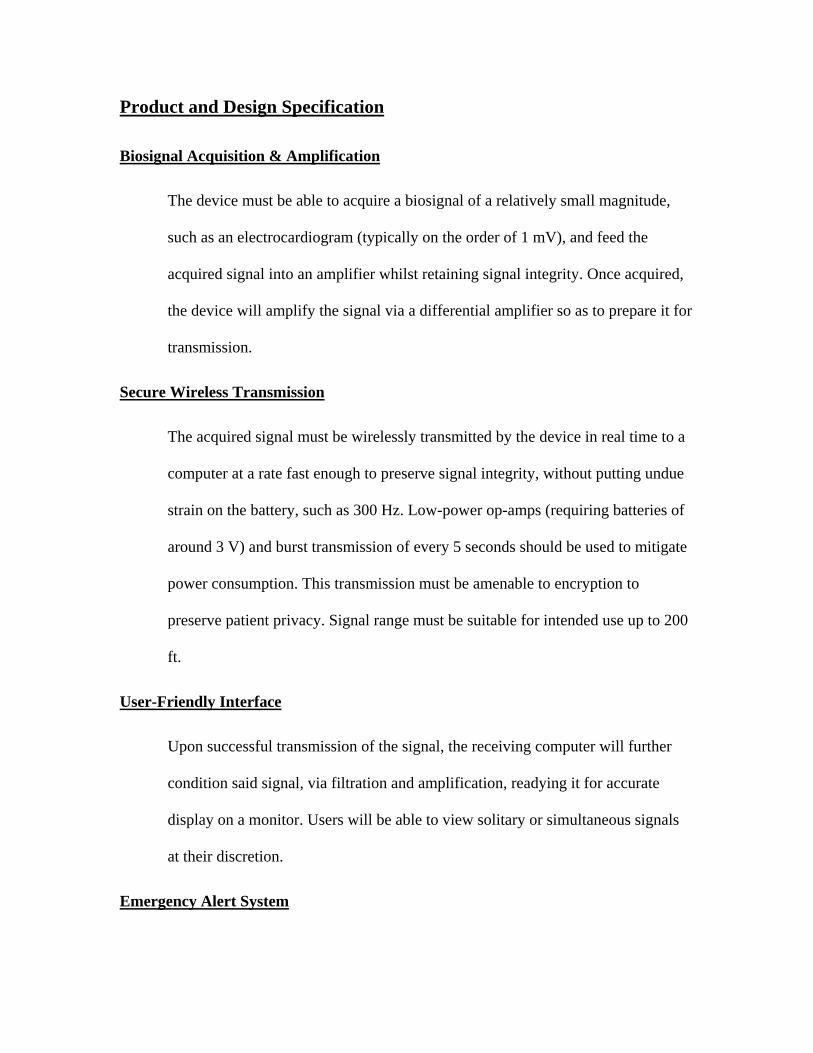
Product and Design Specification
Biosignal Acquisition & Amplification
The device must be able to acquire a biosignal of a relatively small magnitude,
such as an electrocardiogram (typically on the order of 1 mV), and feed the
acquired signal into an amplifier whilst retaining signal integrity. Once acquired,
the device will amplify the signal via a differential amplifier so as to prepare it for
transmission.
Secure Wireless Transmission
The acquired signal must be wirelessly transmitted by the device in real time to a
computer at a rate fast enough to preserve signal integrity, without putting undue
strain on the battery, such as 300 Hz. Low-power op-amps (requiring batteries of
around 3 V) and burst transmission of every 5 seconds should be used to mitigate
power consumption. This transmission must be amenable to encryption to
preserve patient privacy. Signal range must be suitable for intended use up to 200
ft.
User-Friendly Interface
Upon successful transmission of the signal, the receiving computer will further
condition said signal, via filtration and amplification, readying it for accurate
display on a monitor. Users will be able to view solitary or simultaneous signals
at their discretion.
Emergency Alert System

The computer-end of the system will be monitoring the signal. In the event of an
emergency, such as an ECG flat-line or decrease in heart-rate variability [16], the
device will be programmed to send an immediate alert to a pre-determined care
provider.
Scalable Implementation
The entire biosignal monitoring system will be applicable in multiple settings.
Able to wirelessly transmit via a mesh network, the system can be implemented in
a setting requiring many patients in a large area. The system will also be
employable in smaller-scale settings, with only a few units in use.
Physical Durability
The patient-worn device must be compact and portable to allow for mobility.
Additionally, this device must not be easily susceptible to mechanical stress
typically experienced during patient use.
Final Design Description
Our final design incorporates active RF technology on the patient in order to send
data bursts to a central receiver or integrated network of receivers. Synapse wireless
solutions provide superior range for acceptable battery life, and give us the flexibility
necessary to incorporate multiple signals and multiple patients.
Receiver/ Integrated Network
Hardware
Receivers would be placed approximately every 400 feet (200 feet in each
direction would cover this) throughout a hospital or nursing home, or one per
house. These devices are cheap and can be run off of standard AC power, making
them easy to integrate into existing architecture. Due to Synapse’s simple design,
these devices can integrate themselves into the existing network automatically
when plugged in allowing for easy installation. Computers will be connected to
the network allowing for data display and analysis.
Scalability will be built into our system both on the signal level and on the
device level. One device will be able to collect multiple signals and devices will
be able to integrate into an already existing wireless network. Further, multiple
monitoring stations will even be able to be incorporated into a network, allowing
for extensive patient monitoring and care.
Computer Software
Software is programmed in python, and built modularly so that additional
signals can be added easily. A program framework will be developed which will
turn wireless signals into classical computer arrays, and run program cycles at a
determined speed, calling modules at a certain rate. This design will allow
modules to be easily designed for different signals, as programmers won’t have to
worry about the application framework as a whole.
Further, in order to alert medical personal when an emergency occurs our
device is designed to send SMS messages to personnel. Currently nearly
2.4billion people send and receive SMS messages. By implementing such a
system in a hospital setting the outdated alphanumeric pagers currently found in
many hospitals could be replaced with a more modern system in their place.

Patient Worn Device
ECG Amplifier
In general, ECG amplifiers are composed of Instrumentation Amplifiers and Band
Pass Filters. Shown below in figure 5 is an Instrumentation Amplifier, and the
derivation of the gain of such a filter. The gain of the amplifier will then be set to
between 200 and 1000 in order to most accurately fit out ECG signal into the
input range of our Analog-Digital Converter.
Figure 5. Instrumentation Amplifier used to amplify ECG signal.
1
V2 −V1 = I1R1
V 3−V4 = I1(R1 + 2R2)
V 3−V4 = (R1 + 2R2
R1
)(V2 −V1)
V 3−V4 = (1+ 2R2
R1
)(V2 −V1)
2 V0 −V3 = (R3 + R4 ) * I2
V5 −V3 = R3 * I2
V0 −V3 = (R3 + R4
R3
)(V5 −V3)
3.
R3(V5 −V4 ) = −V5R4
R3V5 − R3V4 = −V5R4
(R3 + R4 )V5 = R3V4
V5 =R4
R3 + R4
V4
2 & 3
V0 −V3 = (R3 + R4
R3
)(( R4
R3 + R4
V4 ) −V3)
V0 =R4
R3
V4 − (R3 + R4
R3
)V3 +V3
V0 =R4
R3
V4 − (1+ R4
R3
)V3 +V3
V0 =R4
R3
V4 −R4
R3
V3 =R4
R3
(V4 −V3)

4. V0 =
R4
R3
(2R2
R1
+1)(V2 −V1)
Gain = R4
R3
(2R2
R1
+1)
Band Pass Filter
Further, figure 6 presents a schematic of the band pass filter we plan on
using in the ECG amplifier. This filter has both a low pass a high pass cutoff
frequency. Past these frequencies the amplitude of the biosignal will drop off
rapidly, first at approximately 70% and then more. The transfer function of such
an operational amplifier roughly represents the product of two chebyshev
functions.
Figure 6. Schematic of band pass filter used in ECG amplifier.
Microcontroller and Transmitter
Two models of transmitter and microcontroller systems are available from
Synapse, including a 110mA active transmitter and a scaled down model with a
40mA active transmission current [19]. Our first prototype will use the 110mA-
amplified transmitter in order to get our device running simply and quickly. Later
versions of the device will incorporate the unamplified version of the transmitter,
giving us nearly doubled battery life and the 200-foot range we’ve discussed.
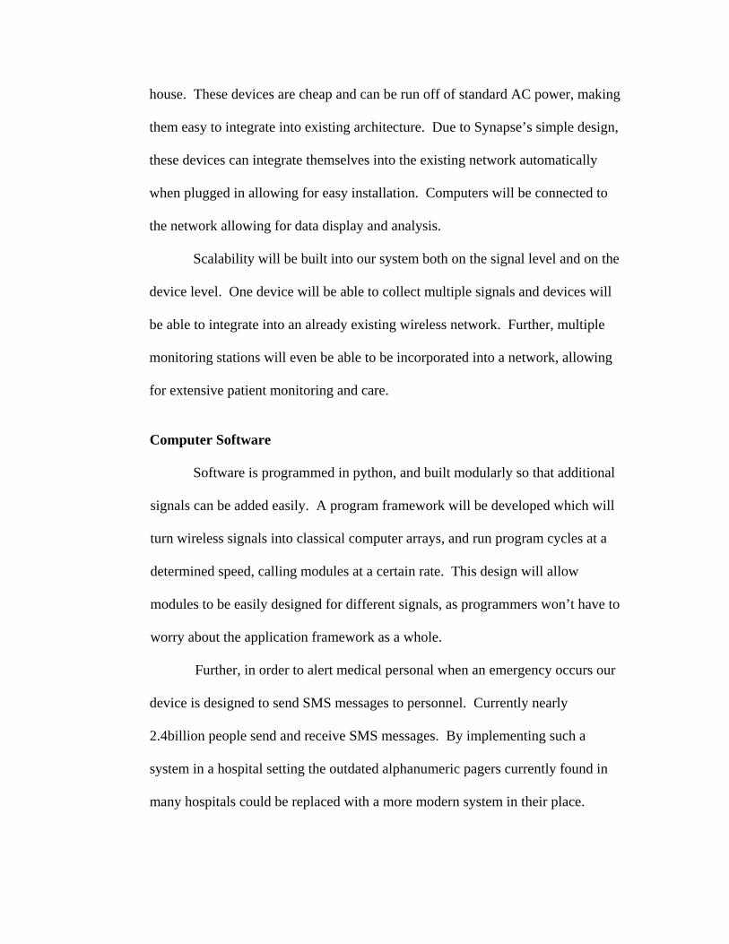
Once our product reaches market both transmitters will be available, offering
greater flexibility in the system. Figure 7 shows a schematic of how the parts of
our prototype connect.
Firmware
Synapse Firmware is programmed
in a language called SNAPPy, a subset of
python created by Synapse Wireless. The
device will be programmed to collect data
for approximately 5 seconds and then send
out a data burst of information for
approximately 1/5 of a second. Further,
patient information will also be sent out
with each burst of data. Calculations of
this ratio are included earlier in a
comparison of alternatives. Further,
firmware will be written in such a
way that multiple signals can be incorporated into one burst and sent out.
Figure 7: RF Engine transmitting to computer receiving antenna
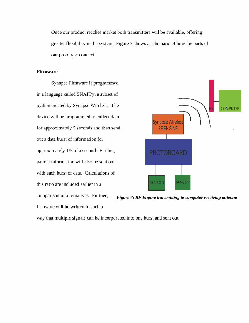
Prototype Description
The ECG amplifier connections were printed onto a printed circuit board, and all of
the circuit components (operation amplifiers, resistors and capacitors) were soldered onto
the board by hand. Multiple different operation amplifiers were tried, all of which were
low power high gain models operating in the bandwidth of an ECG signal (1-120Hz).
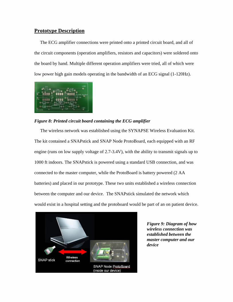
Figure 8: Printed circuit board containing the ECG amplifier The wireless network was established using the SYNAPSE Wireless Evaluation Kit.
The kit contained a SNAPstick and SNAP Node ProtoBoard, each equipped with an RF
engine (runs on low supply voltage of 2.7-3.4V), with the ability to transmit signals up to
1000 ft indoors. The SNAPstick is powered using a standard USB connection, and was
connected to the master computer, while the ProtoBoard is battery powered (2 AA
batteries) and placed in our prototype. These two units established a wireless connection
between the computer and our device. The SNAPstick simulated the network which
would exist in a hospital setting and the protoboard would be part of an on patient device.
Figure 9: Diagram of how wireless connection was established between the master computer and our device
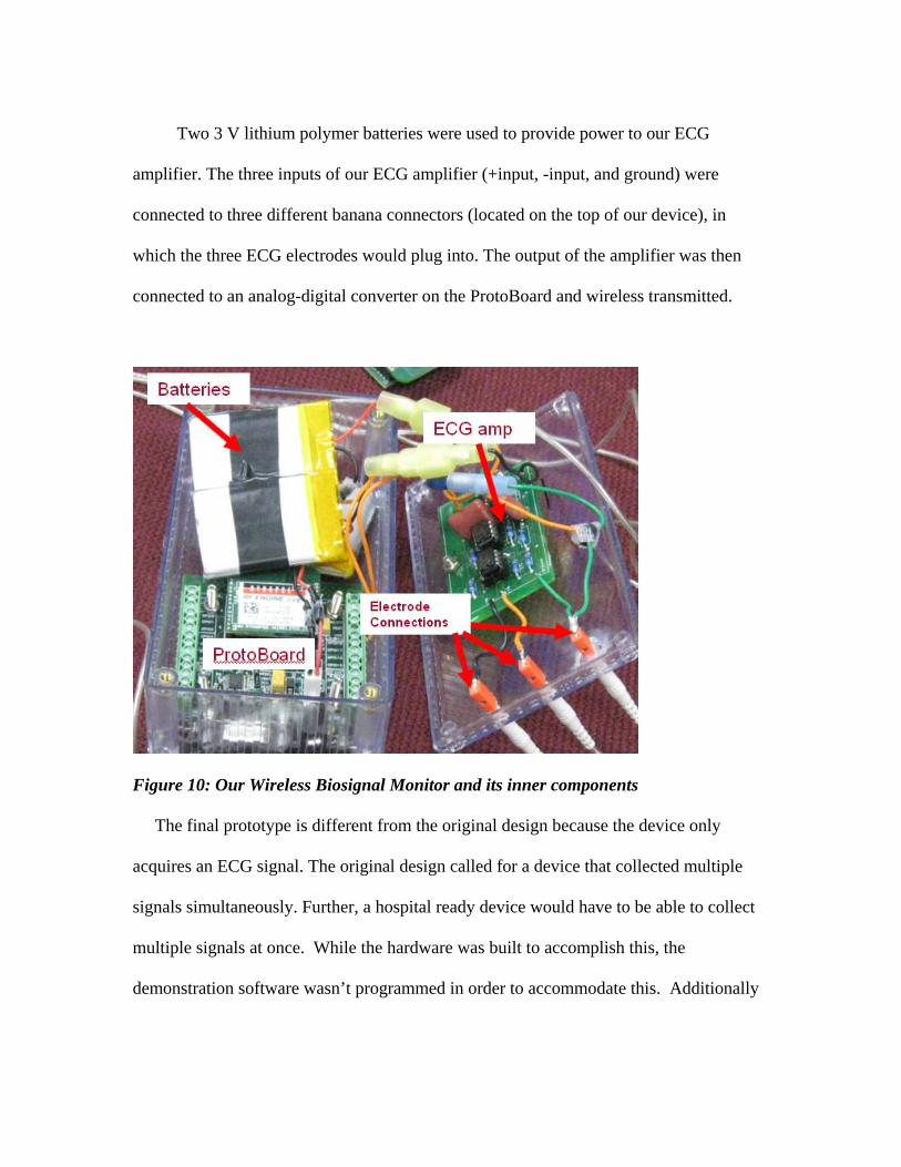
Two 3 V lithium polymer batteries were used to provide power to our ECG
amplifier. The three inputs of our ECG amplifier (+input, -input, and ground) were
connected to three different banana connectors (located on the top of our device), in
which the three ECG electrodes would plug into. The output of the amplifier was then
connected to an analog-digital converter on the ProtoBoard and wireless transmitted.
Figure 10: Our Wireless Biosignal Monitor and its inner components
The final prototype is different from the original design because the device only
acquires an ECG signal. The original design called for a device that collected multiple
signals simultaneously. Further, a hospital ready device would have to be able to collect
multiple signals at once. While the hardware was built to accomplish this, the
demonstration software wasn’t programmed in order to accommodate this. Additionally

the SMS alert system works well, but relies on google to be running properly, a
requirement which may not be suitable for use in healthcare.
Prototype Evaluation and Testing
In terms of product specifications, the Wireless Biosignal Monitor is inexpensive
to a vast profile of customers. The low-cost will increase the rate at which hospitals,
nursing homes and research facilities evolve to wireless systems. Also, the product itself
is relatively durable, being protected by a plastic casing. The other components are by no
means ineffective as a reflection of their prices. The wireless technology is state of the art
and fully developed. Also, due to the simplicity of the design and program, the device can
be utilized as an individual product, or part of an entire wireless network.
The device’s software has also been devised to acquire three hundred data points
per second, enough to show an ECG wave. This real-time monitoring fully accomplishes
the desired goal of displaying the appropriate graph, as well as permitting immediate
responses. The SMS Emergency technology also furthers this, by making use of the
advanced wireless communication services that are available today. The provided
software also comes complimentary with secure connections to prevent interception of
private health information. This hinders unofficial personal from access when in the
vicinity.
The purchased Synapse Wireless receivers also achieved the necessary task of
acquiring multiple signals simultaneously without disruption in signal or confusion in the
display. The components bought are already built to retrieve several different signals,
placing each in a separate visual window in the graphical user interface. The prototype

was able to send two different ECG signals from two patients and responded with the
SMS text when one was disconnected.
The final power source chosen was two 1.5 Volt batteries in series. Although the
battery power was calculated to enough to run the device for several hours without out
recharging, the prototype itself was never functional for more than ten minutes at a time.
There are several different possibilities that can account for this discrepancy; however, a
primary candidate was the overheating of the prototype board. As the prototype designs
evolved, no cooling system was ever conceived.
The modular design criterion of the project has been accomplished with a small
seven by five inch box that weighs less than one pound. It can be easily carried, held or
placed on desktop without any inconvenience to the wearer. The electrodes are adhesive
and easily removable.
The prototype was tested in receiving multiple signals from different sources
simultaneously. The program introduced both graphs for visual analysis without
complications. The signal range was also tested in a hospital like environment. The
Synapse receiver could obtain signals from over ten meters away, through concrete walls,
furniture and other electronics. The SMS Emergency text messaging notification was
used several times, on various cellular networks, for more than a single patient. The only
problems that were evident was that in areas without service, the cell phones themselves
were not able to receive the text until service returned.
All the connectors, soldering and circuitry functioned properly and can be backed
by the sample EKGs of patient achieved from the instrument amplifiers and filters.

Parts List and Cost
First Generation Transmitter and Microcontroller ($150)
For the first generation prototype of our device, we’re going to use the parts from
a Synapse Wireless Network Starter Kit for our RF engine and microcontroller. This
Networking Kit costs $150 through Digikey and includes [20]:
2 RF100PC6 RF Engine SNAPpro F-TYPE Tx Amp
These RF transmitter/Microcontrollers include signal amplification,
allowing us a range greater then the 200feet (up to 1000 feet) our system is
designed on. This increased range and signal power should facilitate testing our
device, and could be incorporated into our network system as a higher tier
alternative. Further, one of these engines is connected to the computer in order to
receive our biosignal. This device should feature to amplification, as power is not
a concern on the computer side.
1 SN132HO-NR SN132 SNAPStick USB Module
This module allows a Synapse Wireless RF Engine to be connected to the
USB port on a computer. This device accurately represents what an in-house
network will compose of, and simulates the network in a hospital environment.
1 SN171GG-NR SN171 Protoboard
The SN 171 Protoboard has a socket to connect a Synapse Wireless RF

engine too and connections for all of the analog inputs and outputs of the engine.
Further, it has connections for both battery power and DC power, allowing for each
device testing.
Also included in the kit are a battery pack, a DC power transformer, 6 copies of
Synapse Wireless’s Portal Software, and a few other tools to make prototyping easy.
Amplifier and Circuit Elements ($50)
Our initial purchase will not include any amplifiers or circuit elements. We
already have a constructed ECG amplifier from previous lab work with Professor Wei
Lin. For testing, we’ll be using this amplifier and a signal generator. However, we’re
allotting $50 for purchases to build the final version of the circuit using low power
amplifiers.
Second Generation Prototype ($200)
After building a device using the already mentioned components, a second
generation device will be built, based entirely off the previous device, using a lower
powered amplifier from Synapse Wireless and a smaller, custom designed protoboard.
This device would eliminate unnecessary connections and components from our device,
decreasing its size by approximately ½ and increasing its battery life by a factor of 2.
RF100P86 RF Engine SNAPpro F-TYPE Tx….$24 (Digikey)
This transmitter doesn’t include the amplification of the previous design,
decreasing device cost while increasing battery life by a factor of 2. Top range is rated at
200m. All connections, programming, and operation will run exactly the same as the
previous device, allowing for an easy transition.
Other money is for a printed circuit board or regular protoboard and a high quality
finished case with plug-type connections for signal wires.
Simulated Hospital Network ($100)
In order to further simulate the environment our system would function in,
additional networking nodes will be added throughout a testing facility to show how
communication could occur. These nodes will collect biosignals from on patient devices,
increase the power of the transmission, and communicate both with other similar nodes
and monitoring stations.
Addition On-Patient Prototypes ($150)
Using the same parts as the first and second generation devices, additional
prototypes will be built to show how multiple units can function together to collect data
from different patients.
Additional Signal Monitoring Device ($150)
In order to demonstrate our devices ability to allow for the collection of multiple
biosignals, additional sensors will be incorporated into the final design. Specifically,
we’re looking at incorporating EMG, Blood pressure measurements, or Blood Oximetry
measurements.
RFID Identification ($200)
In order to incorporate patient identification into our design, RFID technology
will be used. Patients will wear identification bracelets that will contain their name,
patient number, room number, and any other pertinent information. The main device will
contain a RFID interrogator in order to read these tags, and then save the patients
information to its memory.
Total: $1000
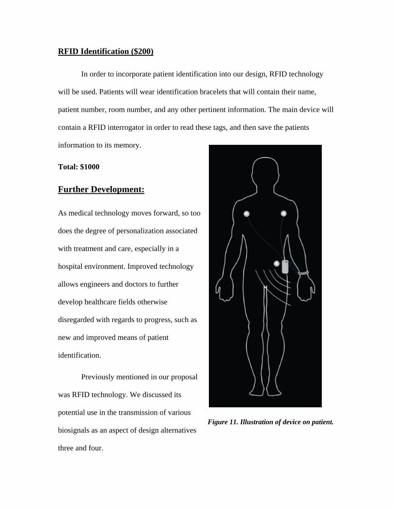
Further Development:
As medical technology moves forward, so too
does the degree of personalization associated
with treatment and care, especially in a
hospital environment. Improved technology
allows engineers and doctors to further
develop healthcare fields otherwise
disregarded with regards to progress, such as
new and improved means of patient
identification.
Previously mentioned in our proposal
was RFID technology. We discussed its
potential use in the transmission of various
biosignals as an aspect of design alternatives
three and four.
Figure 11. Illustration of device on patient.
To reiterate, the technology offers a novel solution for transmitting a reflected
signal, altered in a way that is unique to the individual chip, or ‘tag’ in question. We
originally wanted to use this technology in such a way that, through altering the returned
(or reflected) signal, we would be able to transmit biological signal data, such as an ECG.
Upon reviewing the specifics of the design alternatives using RFID it became clear that
the ratio of expected signal transmission range to battery size was far too small to be of
practical use in a hospital or home care setting; the maximum range found experimentally
to date has been no greater than the order of 10 – 15 m (21).
Successful commercial implementations of RFID technology thus far have
required such relatively short-range signal transmission ranges. Common examples are
package-tracking (22), ‘smart’ chips (23), tap-and-pay credit cards (24) and security
sensors in retail stores or libraries (25); systems in which the RFID tag is either
‘scanned,’ meaning held within inches of the signal-reader, or picked up by the reader
from a distance of several feet.
A similar system could be implemented in accordance with our proposed Wireless
Biosignal Monitor; RFID chips coded with patient information (such as patient name,
hospital ID, room number, etc.) could be inserted in an identification bracelet similar to
those currently distributed by hospitals. The biosignal monitoring device would be
equipped with basic RFID reader technology; upon being affixed to the patient, the ID
bracelet could simply be swiped near the body of the signal transmitter/receiver, and the

patient information would be sent to the reader computer along with their biological data.
The appeal of this addition to our Wireless Biosignal Monitor lies in the
convenience and efficiency of digitally attaching a name to a monitored signal. The
nature of our design incorporates modularity, meaning a mainframe computer would read
multiple signals simultaneously; having a name attached to each signal would prevent
confusion when an observer is looking at the computer screen.

References: 1) ‘ECG’. Children’s Hospital Boston. Harvard Medical School. 2005-2007 <http://www.childrenshospital.org/az/Site494/mainpageS494P0.html>.
2). ‘ECG’. Science Clarified. AdvancedMed. Inc. 19 December 2008 http://www.scienceclarified.com/El-Ex/Electrocardiogram.html
3) Heart Attack Information and Sumptoms. National Heart, Lung, and Blood Institute (NHLBI) <http://www.apsfa.org/heartattack.htm>.
4) Yang G, Cao Y, Chen J, Tenhuen H, Zheng L. 2008. An Active-Cable Connected ECG monitoring System for Ubiquitous Healthcare. IEEE Computer Society. 101:392 397. http://doi.ieeecomputersociety.org/10.1109/ICCIT.2008.101
5) Shandle J. 2008. Remote medical monitoring. A new telehealth age dawns. Electronic Engineering Times. 1545:24;26. <http://web.ebscohost.com.libproxy.cc.stonybrook.edu/ehost/detail?vid=1&hid=16&s id=ab039338-478a-46a8-82b5-6710fe6736b6% 40sessionmgr9&bdata= JnNpdGU9ZWhvc3Qtb l2ZQ%3d%3d#db=buh&AN=34839873>.
6) Hu F, Calentano L, Xiao Y. 2009. Error-resistant RFID-assisted wireless sensor network for cardiac telehealthcare. Wirel. Commun. Mob. Comput. 9:85101 http://www3.interscience.wiley.com.libproxy.cc.stonybrook.edu/cgibin/fulltext/117923052/PDFSTART.
7) “The unnecessary cost of technology.” HalfMD. <http://halfmd.wordpress.com/2008/06/02/the-unnecessary-cost-of-technology/>.
8) Medical Device Depot. EKG Machines. 19 December 2008 http://www.medicaldevicedepot.com/EKG-Machiness/29.htm?gclid=COS0wLLPsJcCFQxKGgodwTkBjg
9) Online digital filter and QRS detector applicable in low resource ECG monitoring systems. Tabakov, Serafim; Iliev, Ivo; Krasteva, Vessela. Annals of Biomedical Engineering (0090-6964)November, 2008. Vol.36,Iss.11;p.1805-1815
10) C Karlof, D. Wagner. “Secure routing in wireless sensor networks: Attacks and countermeasures.” 1st IEEE International Workshop on Sensor Network Protocols and Applications. 2003.
11) De Bruyne et al “Diagnostic interpretation of electrocardiograms in population-based research: Computer program research physicians, or cardiologists?” Journal of Clinical Epidemiology, vol 50 , Issue 8 , P 947 – 952.
12) "Radio Frequency Identification (RFID)." TelecomSpace. <http://www.telecomspace.com/wirelessnw-rfid.html>.
13) Nave, R. "Faraday's Law." Electricity and Magnetism. HyperPhysics. <http://www.mwit.ac.th/~physicslab/hbase/electric/farlaw.html>.
14) Roberti, Mark. "Sensing New RFID Opportunities." RFID Journal -The World's RFID Authority. http://www.rfidjournal.com/article/articleview/2081/>.
15) Crumley, Glen C., Noel E. Evans, and William G. Scanlon. "The Design and Performance of a 2.5-GHz telecommand Link for Wireless Biomedical Monitoring." IEEE Transactions on Information Technology in Biomedicine 4 (2000): 285-91.
16) Fauchier et al. Prognostic Value of Heart Rate Variability for Sudden Death and Major Arrhythmic Events in Patients With Idiopathic Dilated Cardiomyopathy. J Amer Col Card. 1999. 33;5;1203-7.
17) Hopman, Nicholas C., Daniel L. Williams, and Franco Lodato. Wireless electrocardiograph system and method. Motorola, Inc., assignee. Patent 6611705. 2003.
18) DeLuca, Carlo J., Per Bergman, Gianluca DeLuca, and Donald Gilmore. Biosignal Monitoring System and Method. Altec, Inc. Boston, MA, assignee. Patent 6238338. 2001.
19) SYNAPSE RF Engine IEEE 802.15.4 RF Modules. < http://www.synapsewireless.com/documents/products/SYNAPSE_RF_Engine.pdf> Accessed December 19, 2008.
20) SYNAPSE Evaluation Kit EK2100. < http://www.synapsewireless.com/documents/products/SYNAPSE_EK2100_StarterKit.pdf> Accessed December 19, 2008.

21) F. Asif and M. Mandviwalla, “Integrating the supply chain with RFID: a technical and business analysis, communications of the Association for Information Systems,” 15(24) (2005) 8–42.
22) C. Li, L. Liu, S. Chen, C.C. Wu, C. Huang, X. Chen, “Mobile healthcare service system using RFID, in: Proceedings of IEEE International Conference on Networking, Sensing and Control,” vol. 2, 2004.
23) M. Schneider. “Radio Frequency Identification (RFID) Technology and its Applications in the Commercial Construction Industry,” University of Kentucky, Department of Mechanical Engineering. Apr 2003.
24) A. Jules, RFID security and privacy: A research survey. IEEE Journal on Selected Areas in Communication, 24(2), February 2006.
25) D. Molnar and D. Wagner, “Privacy and Security in Library RFID Issues, Practices, and Architectures,” Conference on Computer and Communication Security, 2004.