Business Class M2 -...
147
BUSINESS CLASS M2 MAINTENANCE MANUAL Models: M2 100 M2 106 M2 106V M2 112 M2 112V STI-455-4 (9/11) Published by Daimler Trucks North America LLC 4747 N. Channel Ave. Portland, OR 97217 Printed in U.S.A.
Transcript of Business Class M2 -...

BUSINESS CLASS M2 MAINTENANCE MANUAL
Models: M2 100M2 106M2 106VM2 112M2 112V
STI-455-4 (9/11) Published byDaimler Trucks North America LLC
4747 N. Channel Ave.Portland, OR 97217
Printed in U.S.A.

ForewordPerforming scheduled maintenance operations is important in obtaining safe, reliable operationof your vehicle. A proper maintenance program will also help to minimize downtime andsafeguard warranties.
IMPORTANT: The maintenance operations in this manual are not all-inclusive . Alsorefer to other component and body manufacturers’ instructions for specific inspectionand maintenance instructions.
Perform the operations in this maintenance manual at scheduled intervals. Perform the pretripand post-trip inspections, and daily/weekly/monthly maintenance, as outlined in the vehicledriver’s manual. Major components, such as engines, transmissions, and rear axles, are coveredin their own maintenance and operation manuals, that are provided with the vehicle. Perform anymaintenance operations listed at the intervals scheduled in those manuals. Your FreightlinerDealership has the qualified technicians and equipment to perform this maintenance for you.They can also set up a scheduled maintenance program tailored specifically to your needs.Optionally, they can assist you in learning how to perform these maintenance procedures.
IMPORTANT: Descriptions and specifications in this manual were in effect at the time ofprinting. Freightliner Trucks reserves the right to discontinue models and to changespecifications or design at any time without notice and without incurring obligation.Descriptions and specifications contained in this publication provide no warranty,expressed or implied, and are subject to revision and editions without notice.
Refer to www.Daimler-TrucksNorthAmerica.com and www.FreightlinerTrucks.com for moreinformation, or contact Daimler Trucks North America LLC at the address below.
Environmental Concerns and RecommendationsWhenever you see instructions in this manual to discard materials, you should attempt to reclaimand recycle them. To preserve our environment, follow appropriate environmental rules andregulations when disposing of materials.
NOTICE: Parts Replacement ConsiderationsDo not replace suspension, axle, or steering parts (such as springs, wheels, hubs, and steeringgears) with used parts. Used parts may have been subjected to collisions or improper use andhave undetected structural damage.
© 2001–2011 Daimler Trucks North America LLC
All rights reserved. No part of this publication, in whole or in part, may be translated, reproduced,stored in a retrieval system, or transmitted in any form by any means, electronic, mechanical,photocopying, recording, or otherwise, without the prior written permission of Daimler TrucksNorth America LLC. Daimler Trucks North America LLC is a Daimler company.
Daimler Trucks North America LLCService Systems and Documentation (CVI-SSD)
P.O. Box 3849Portland, Oregon 97208-3849

Daimler Trucks North America LLC distributes the following major service publications in paper and electronic(via ServicePro®) formats.
Workshop/ServiceManual
Workshop/service manuals contain service and repair information for all vehiclesystems and components, except for major components such as engines, trans-missions, and rear axles. Each workshop/service manual section is divided intosubjects that can include general information, principles of operation, removal,disassembly, assembly, installation, and specifications.
Maintenance Manual Maintenance manuals contain routine maintenance procedures and intervals forvehicle components and systems. They have information such as lubricationprocedures and tables, fluid replacement procedures, fluid capacities, specifica-tions, and procedures for adjustments and for checking the tightness of fasten-ers. Maintenance manuals do not contain detailed repair or service information.
Driver’s/Operator’sManual
Driver’s/operator’s manuals contain information needed to enhance the driver’sunderstanding of how to operate and care for the vehicle and its components.Each manual contains a chapter that covers pretrip and post-trip inspections,and daily, weekly, and monthly maintenance of vehicle components.Driver’s/operator’s manuals do not contain detailed repair or service information.
Service Bulletins Service bulletins provide the latest service tips, field repairs, product improve-ments, and related information. Some service bulletins are updates to informa-tion in the workshop/service manual. These bulletins take precedence overworkshop/service manual information, until the latter is updated; at that time, thebulletin is usually canceled. The service bulletins manual is available only todealers. When doing service work on a vehicle system or part, check for a validservice bulletin for the latest information on the subject.
IMPORTANT: Before using a particular service bulletin, check the currentservice bulletin validity list to be sure the bulletin is valid.
Parts Technical Bulletins Parts technical bulletins provide information on parts. These bulletins containlists of parts and BOMs needed to do replacement and upgrade procedures.
Web-based repair, service, and parts documentation can be accessed using the following applications on theAccessFreightliner.com website.
ServicePro ServicePro® provides Web-based access to the most up-to-date versions of thepublications listed above. In addition, the Service Solutions feature provides di-agnostic assistance with Symptoms Search, by connecting to a large knowledgebase gathered from technicians and service personnel. Search results for bothdocuments and service solutions can be narrowed by initially entering vehicleidentification data.
PartsPro PartsPro® is an electronic parts catalog system, showing the specified vehicle’sbuild record.
EZWiring EZWiring™ makes Freightliner, Sterling, Western Star, Thomas Built Buses, andFreightliner Custom Chassis Corporation products’ wiring drawings and floatingpin lists available online for viewing and printing. EZWiring can also be ac-cessed from within PartsPro.
IntroductionDescriptions of Service Publications
Business Class M2 Maintenance Manual, May 2011 I–1

Warranty-related service information available on the AccessFreightliner.com website includes the followingdocumentation.
Recall Campaigns Recall campaigns cover situations that involve service work or replacement ofparts in connection with a recall notice. These campaigns pertain to matters ofvehicle safety. All recall campaigns are distributed to dealers; customers receivenotices that apply to their vehicles.
Field Service Campaigns Field service campaigns are concerned with non-safety-related service work orreplacement of parts. All field service campaigns are distributed to dealers; cus-tomers receive notices that apply to their vehicles.
IntroductionDescriptions of Service Publications
I–2 Business Class M2 Maintenance Manual, May 2011

For an example of a Business Class M2 Maintenance Manual page, see Fig. 1 .
f020125
A B C
D E
Cooling
12/06/2001
Business Class M2 Maintenance Manual, December 2001
20−01 Coolant Replacement
20−02 Cooling Fan Inspection
20
A. Maintenance Operation Number consists of the Group Number followed by the Sequence NumberB. Group TitleC. Group NumberD. Release DateE. Group Number/Page Number
Fig. 1, Example of a Business Class M2 Maintenance Manual Page
IntroductionPage Description
Business Class M2 Maintenance Manual, May 2011 I–3

Group No. Group Title
00 . . . . . . . . . . . . . . . . . . . . . . General Information01 . . . . . . . . . . . . . . . . . . . . . . . . . . . . . . . . Engine09 . . . . . . . . . . . . . . . . . . . . . . . . . . . . . . Air Intake13 . . . . . . . . . . . . . . . . . . . . . . . . . Air Compressor15 . . . . . . . . . . . . . . . . . . . Alternators and Starters20 . . . . . . . . . . . . . . . . . . . Engine Cooling/Radiator25 . . . . . . . . . . . . . . . . . . . . . . . . . . . . . . . . Clutch26 . . . . . . . . . . . . . . . . . . . . . . . . . . . Transmission31 . . . . . . . . . . . . . Frame and Frame Components32 . . . . . . . . . . . . . . . . . . . . . . . . . . . . Suspension33 . . . . . . . . . . . . . . . . . . . . . . . . . . . . . Front Axle35 . . . . . . . . . . . . . . . . . . . . . . . . . . . . . Rear Axle40 . . . . . . . . . . . . . . . . . . . . . . . . Wheels and Tires41 . . . . . . . . . . . . . . . . . . . . . . . . . . . . . . Driveline42 . . . . . . . . . . . . . . . . . . . . . . . . . . . . . . . . Brakes46 . . . . . . . . . . . . . . . . . . . . . . . . . . . . . . . Steering47 . . . . . . . . . . . . . . . . . . . . . . . . . . . . . . . . . Fuel49 . . . . . . . . . . . . . . . . . . . . . . . . . . . . . . . Exhaust60 . . . . . . . . . . . . . . . . . . . . . . . . . . . . . . . . . . Cab72 . . . . . . . . . . . . . . . . . . . . . . . . . . . . . . . . Doors83 . . . . . . . . . . . . . . . . . Heater and Air Conditioner88 . . . . . . . . . . . . . . Hood, Grille, and Cab Fenders
IntroductionMaintenance Manual Contents
I–4 Business Class M2 Maintenance Manual, May 2011
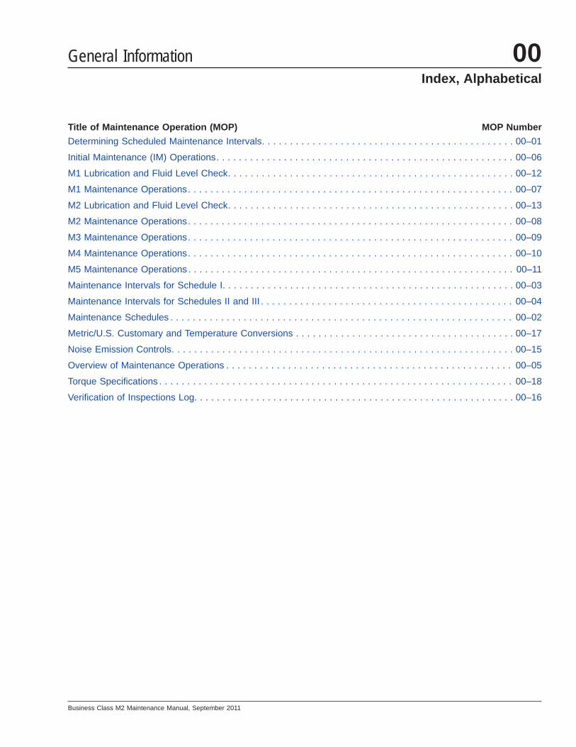
Title of Maintenance Operation (MOP) MOP Number
Determining Scheduled Maintenance Intervals. . . . . . . . . . . . . . . . . . . . . . . . . . . . . . . . . . . . . . . . . . . . . 00–01
Initial Maintenance (IM) Operations. . . . . . . . . . . . . . . . . . . . . . . . . . . . . . . . . . . . . . . . . . . . . . . . . . . . . 00–06
M1 Lubrication and Fluid Level Check. . . . . . . . . . . . . . . . . . . . . . . . . . . . . . . . . . . . . . . . . . . . . . . . . . . 00–12
M1 Maintenance Operations. . . . . . . . . . . . . . . . . . . . . . . . . . . . . . . . . . . . . . . . . . . . . . . . . . . . . . . . . . 00–07
M2 Lubrication and Fluid Level Check. . . . . . . . . . . . . . . . . . . . . . . . . . . . . . . . . . . . . . . . . . . . . . . . . . . 00–13
M2 Maintenance Operations. . . . . . . . . . . . . . . . . . . . . . . . . . . . . . . . . . . . . . . . . . . . . . . . . . . . . . . . . . 00–08
M3 Maintenance Operations. . . . . . . . . . . . . . . . . . . . . . . . . . . . . . . . . . . . . . . . . . . . . . . . . . . . . . . . . . 00–09
M4 Maintenance Operations. . . . . . . . . . . . . . . . . . . . . . . . . . . . . . . . . . . . . . . . . . . . . . . . . . . . . . . . . . 00–10
M5 Maintenance Operations . . . . . . . . . . . . . . . . . . . . . . . . . . . . . . . . . . . . . . . . . . . . . . . . . . . . . . . . . . 00–11
Maintenance Intervals for Schedule I. . . . . . . . . . . . . . . . . . . . . . . . . . . . . . . . . . . . . . . . . . . . . . . . . . . . 00–03
Maintenance Intervals for Schedules II and III . . . . . . . . . . . . . . . . . . . . . . . . . . . . . . . . . . . . . . . . . . . . . 00–04
Maintenance Schedules . . . . . . . . . . . . . . . . . . . . . . . . . . . . . . . . . . . . . . . . . . . . . . . . . . . . . . . . . . . . . 00–02
Metric/U.S. Customary and Temperature Conversions . . . . . . . . . . . . . . . . . . . . . . . . . . . . . . . . . . . . . . . 00–17
Noise Emission Controls. . . . . . . . . . . . . . . . . . . . . . . . . . . . . . . . . . . . . . . . . . . . . . . . . . . . . . . . . . . . . 00–15
Overview of Maintenance Operations . . . . . . . . . . . . . . . . . . . . . . . . . . . . . . . . . . . . . . . . . . . . . . . . . . . 00–05
Torque Specifications . . . . . . . . . . . . . . . . . . . . . . . . . . . . . . . . . . . . . . . . . . . . . . . . . . . . . . . . . . . . . . . 00–18
Verification of Inspections Log. . . . . . . . . . . . . . . . . . . . . . . . . . . . . . . . . . . . . . . . . . . . . . . . . . . . . . . . . 00–16
General Information 00Index, Alphabetical
Business Class M2 Maintenance Manual, September 2011

Determining ScheduledMaintenance IntervalsPerforming regular maintenance will help ensure thatyour vehicle delivers safe, reliable service and opti-mum performance. A proper maintenance programwill also help to minimize downtime and safeguardwarranties.
To determine the correct maintenance intervals foryour vehicle, you must first determine the type of ser-vice or conditions the vehicle will be operating in.Most vehicles operate in conditions that fall withinone of the three schedules. Before placing your ve-hicle in service, determine whether Schedule I, II, orIII applies to your vehicle.
Schedules I-IIISchedule I (severe service) applies to vehicles thattravel up to 6000 miles (10 000 kilometers) annuallyor that operate under severe conditions. Examples ofSchedule I usage are:
• operation on extremely poor roads or wherethere is heavy dust accumulation
• constant exposure to extreme hot, cold, salt air,or other extreme climates
• frequent short-distance travel
• construction-site operation
• city operation such as fire truck and garbagetruck.
• farm operation
Schedule II (short-haul transport) applies to vehiclesthat travel up to 60,000 miles (100 000 kilometers)annually and operate under normal conditions. Ex-amples of Schedule II usage are:
• operation primarily in cities and densely popu-lated areas
• local transport with infrequent freeway travel
• high percentage of stop-and-go travel
Schedule III (long-haul transport) is for vehicles thattravel more than 60,000 miles (100 000 kilometers)annually with minimal city or stop-and-go operation.Examples of Schedule III usage are:
• regional delivery that is mostly freeway miles
• interstate transport
• any road operation with high annual mileage
Maintenance SchedulesAfter determining the schedule appropriate to yourvehicle, refer to the Maintenance Schedules to deter-mine when to perform the Initial Maintenance (IM)and the frequency of performing subsequent mainte-nance intervals for each schedule.
Maintenance IntervalsRefer to Maintenance Intervals for Schedule I,Schedule II, and Schedule III to determine whichmaintenance interval(s) should be performed whenyour vehicle reaches the mileage or hours of opera-tion listed in these tables.
Maintenance OperationsGroups 01 through 83 in this manual have an indexat the beginning of each Group. The index lists theTitle of Maintenance Operations and the mainte-nance Operation (MOP) Numbers for that Group.Follow the instructions under the MOP number toperform the required maintenance.
In addition to the maintenance operations requiredfor the maintenance interval, perform all the dailymaintenance procedures in Chapter 11 , "Pretrip In-spection and Daily Maintenance," in the BusinessClass® M2 Driver’s Manual.
General Information 00Determining Scheduled Maintenance Intervals: 00–01
Business Class M2 Maintenance Manual, September 2011 00/1

Maintenance Schedules
ScheduleMaintenance Intervals
Maintenance Interval Frequency Mileage km Hours
Schedule I *(severe service)
for vehicles that travel up to6000 miles (10 000 km) annually
Initial Maintenance (IM) first 1000 1600 100
Maintenance 1 (M1) every 1000 1600 100
Maintenance 2 (M2) every 4000 6400 400
Maintenance 3 (M3) every 8000 12 800 800
Maintenance 4 (M4) every 16,000 25 600 1600
Maintenance 5 (M5) every 32,000 51 200 3200
Schedule II(short-haul transport)
for vehicles that travel up to60,000 miles (100 000 km)
annually
Initial Maintenance (IM) first 8000 12 000
—
Maintenance 1 (M1) every 8000 12 000
Maintenance 2 (M2) every 16,000 24 000
Maintenance 3 (M3) every 32,000 48 000
Maintenance 4 (M4) every 64,000 96 000
Maintenance 5 (M5) every 128,000 192 000
Schedule III(long-haul transport)
for vehicles that travel over60,000 miles (100 000 km)
annually
Initial Maintenance (IM) first 10,000 16 000
—
Maintenance 1 (M1) every 10,000 16 000
Maintenance 2 (M2) every 20,000 32 000
Maintenance 3 (M3) every 40,000 64 000
Maintenance 4 (M4) every 80,000 128 000
Maintenance 5 (M5) every 160,000 256 000* For Schedule I vehicles equipped with an hourmeter, use maintenance intervals based on hours of operation rather than mileage.
Table 1, Maintenance Schedules
General Information00Maintenance Schedules: 00–02
Business Class M2 Maintenance Manual, September 201100/2
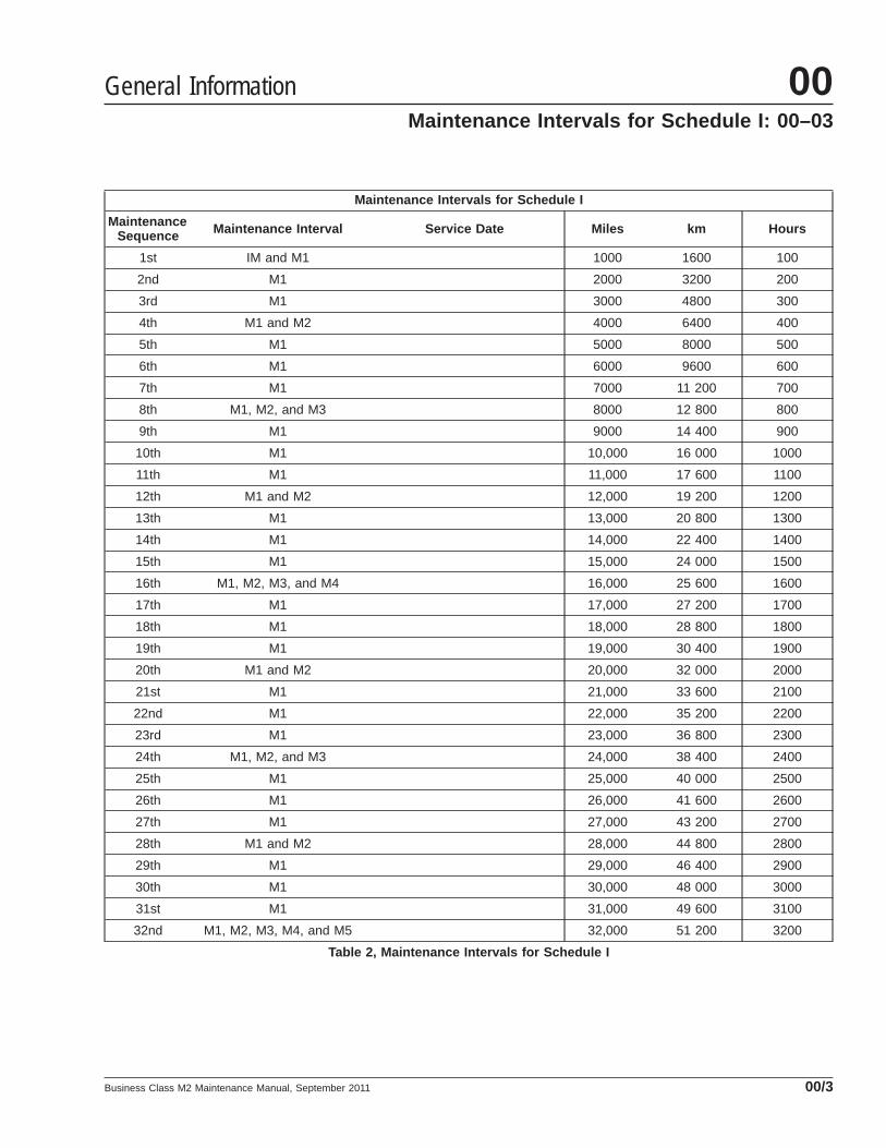
Maintenance Intervals for Schedule I
MaintenanceSequence Maintenance Interval Service Date Miles km Hours
1st IM and M1 1000 1600 100
2nd M1 2000 3200 200
3rd M1 3000 4800 300
4th M1 and M2 4000 6400 400
5th M1 5000 8000 500
6th M1 6000 9600 600
7th M1 7000 11 200 700
8th M1, M2, and M3 8000 12 800 800
9th M1 9000 14 400 900
10th M1 10,000 16 000 1000
11th M1 11,000 17 600 1100
12th M1 and M2 12,000 19 200 1200
13th M1 13,000 20 800 1300
14th M1 14,000 22 400 1400
15th M1 15,000 24 000 1500
16th M1, M2, M3, and M4 16,000 25 600 1600
17th M1 17,000 27 200 1700
18th M1 18,000 28 800 1800
19th M1 19,000 30 400 1900
20th M1 and M2 20,000 32 000 2000
21st M1 21,000 33 600 2100
22nd M1 22,000 35 200 2200
23rd M1 23,000 36 800 2300
24th M1, M2, and M3 24,000 38 400 2400
25th M1 25,000 40 000 2500
26th M1 26,000 41 600 2600
27th M1 27,000 43 200 2700
28th M1 and M2 28,000 44 800 2800
29th M1 29,000 46 400 2900
30th M1 30,000 48 000 3000
31st M1 31,000 49 600 3100
32nd M1, M2, M3, M4, and M5 32,000 51 200 3200
Table 2, Maintenance Intervals for Schedule I
General Information 00Maintenance Intervals for Schedule I: 00–03
Business Class M2 Maintenance Manual, September 2011 00/3

Maintenance Intervals for Schedules II and III
MaintenanceSequence Maintenance Interval Service Date
Schedule II Schedule III
Miles km Miles km
1st IM and M1 8000 12 000 10,000 16 000
2nd M1 and M2 16,000 24 000 20,000 32 000
3rd M1 24,000 36 000 30,000 48 000
4th M1, M2, and M3 32,000 48 000 40,000 64 000
5th M1 40,000 60 000 50,000 80 000
6th M1 and M2 48,000 72 000 60,000 96 000
7th M1 56,000 84 000 70,000 112 000
8th M1, M2, M3, and M4 64,000 96 000 80,000 128 000
9th M1 72,000 108 000 90,000 144 000
10th M1 and M2 80,000 120 000 100,000 160 000
11th M1 88,000 132 000 110,000 176 000
12th M1, M2, and M3 96,000 144 000 120,000 192 000
13th M1 104,000 156 000 130,000 208 000
14th M1, and M2 112,000 168 000 140,000 224 000
15th M1 120,000 180 000 150,000 240 000
16th M1, M2, M3, M4, and M5 128,000 192 000 160,000 256 000
17th M1 136,000 204 000 170,000 272 000
18th M1 and M2 144,000 216 000 180,000 288 000
19th M1 152,000 228 000 190,000 304 000
20th M1, M2, and M3 160,000 240 000 200,000 320 000
21st M1 168,000 252 000 210,000 336 000
22nd M1 and M2 176,000 264 000 220,000 352 000
23rd M1 184,000 276 000 230,000 368 000
24th M1, M2, M3, and M4 192,000 288 000 240,000 384 000
25th M1 200,000 300 000 250,000 400 000
26th M1 and M2 208,000 312 000 260,000 416 000
27th M1 216,000 324 000 270,000 432 000
28th M1, M2, and M3 224,000 336,000 280,000 448 000
29th M1 232,000 348 000 290,000 464 000
30th M1 and M2 240,000 360 000 300,000 480 000
31st M1 248,000 372 000 310,000 496 000
32nd M1, M2, M3, M4, and M5 256,000 384 000 320,000 512 000
Table 3, Maintenance Intervals for Schedules II and III
General Information00Maintenance Intervals for Schedules II and III: 00–04
Business Class M2 Maintenance Manual, September 201100/4

Maintenance Operations for Groups 00 through 88
MaintenanceOperation No. Title of Maintenance Operation
Maintenance Intervals
IM M1 M2 M3 M4 M5
01-01 Engine Drive Belt Inspecting • • •
01-02 Engine Support Fastener Checking • •
09-01 Air Cleaner Element Inspecting and Replacing • •
13-01 Air Compressor Inspecting • • • •
15-01 Alternator, Battery, and Starter Checking • •
20-01 Radiator Cap Inspecting • • • •
20-02 Radiator Pressure Flushing and Coolant Changing • •
20-03 Fan Drive Inspecting (Noise Emission Control) • • • •
20-04 Hybrid Electric System Coolant Changing • •
25-01 Eaton Fuller Clutch Release Bearing Lubricating • • • • • •
25-02 Eaton Fuller Clutch Release Cross-Shaft Lubricating • • • • • •
25-03 Clutch Hydraulic Fluid Level Checking • • • • •
25-04 Clutch Hydraulic Fluid Changing •
25-05 Clutch Adjusting, Manually Adjusted Clutches • • • • • •
26-01 Manual Transmission Fluid Level Checking • • • •
26-02 Eaton Fuller Transmission Fluid Changing and Magnetic PlugCleaning* • • • •
26-03 Allison and Eaton Fuller Transmission Breather Checking • • • • • •
26-04 Eaton Fuller Transmission Air Filter/Regulator ElementCleaning • • • •
26-05 Allison Transmission Fluid and Filter Changing • • •
26-06 Mercedes-Benz Transmission Fluid Changing and MagneticPlug Cleaning •
26-07 Mercedes-Benz Transmission Leak Checking •
31-01 Frame Fastener Torque Checking • • •
31-02 Fifth Wheel Inspecting • • • • • •
31-03 Fifth Wheel Lubricating • • • • • •
31-04 Trailer Electrical Connector Lubricating • • • • • •
32-01 Suspension Inspecting • • • • • •
32-02 Suspension Lubricating • • • • • •
32-03 Suspension U-Bolt Torque Checking • • • •
33-01 Kingpin Lubricating • • • • • •
33-02 Tie Rod End Lubricating • • • • • •
33-03 Draw Key Nut Torque Checking • • • •
33-04 Tie Rod End Inspecting • • • • • •
General Information 00Overview of Maintenance Operations: 00–05
Business Class M2 Maintenance Manual, September 2011 00/5

Maintenance Operations for Groups 00 through 88
MaintenanceOperation No. Title of Maintenance Operation
Maintenance Intervals
IM M1 M2 M3 M4 M5
33-05 Wheel End Inspection and Maintenance, 6,000-Pound and8,000-Pound Steer Axles with Oil-Lubricated Hubs† • • • • • •
35-01 Axle Lubricant Level Checking • • • •
35-02 Axle Breather Checking • • • • • •
35-03 Axle Lubricant Changing and Magnetic Plug Cleaning • •
40-01 Wheel Nut Checking • • •
41-01 Driveline Inspecting • • • • • •
41-02 Driveline Lubricating • • • • • •
42-01 Air Brake System Valve Inspecting • • • • • •
42-02 Bendix AD–9 Air Dryer Desiccant Replacing‡ • • • • •
42-03 Governor D–2A Checking • •
42-04 Bosch Hydraulic Brake System Inspecting • • • • • •
42-05 Bendix AD–IP Air Dryer Desiccant Replacing‡ • • • • •
42-06 Haldex and Gunite Slack Adjuster Lubricating • • • • • •
42-07 Meritor Camshaft Bracket Lubricating • • • •
42-08 Meritor Slack Adjuster Lubricating • • • • • •
42-09 Bendix AD–IS Air Dryer Desiccant Replacing‡ • • • • •
42-10 Air Dryer AD–9, AD–IP, and AD–IS/DRM Checking • • • •
42-11 Brake Lines and Fittings Inspecting, Hydraulic Brakes • • • • • •
42-12 Brake Pedal Linkage and Mounting Plate Inspecting • • • •
42-13 Air Brake Inspecting and Leak Testing • • •
42-14 Foot-Control Valve, E6, Inspecting and Lubricating •
42-15 Brake Inspecting • • • • • •
42-16 Bendix Hydro-Max® Brake System Inspecting • • • • • •
46-01 Drag Link Inspecting • • •
46-02 Power Steering Fluid Changing • •
46-03 Power Steering Fluid Level Inspecting • • • •
46-04 Power Steering Gear Lubricating • • • • • •
46-05 Drag Link Lubricating • • • • • •
46-06 Power Steering Filter Changing •
47-01 Fuel Tank Band Nut Tightening •
47-02 Fuel/Water Separator Element Replacing • •
47-03 LNG Fuel System Inspecting • • • • •
47-04 LNG Vacuum Integrity Testing • • •
47-05 CNG Fuel System Inspecting • • • •
General Information00Overview of Maintenance Operations: 00–05
Business Class M2 Maintenance Manual, September 201100/6

Maintenance Operations for Groups 00 through 88
MaintenanceOperation No. Title of Maintenance Operation
Maintenance Intervals
IM M1 M2 M3 M4 M5
47-06 CNG High-Pressure Fuel Filter Element Replacing • • • • •
47-07 CNG Fuel Cylinder Inspecting • • •
49-01 Exhaust System Inspecting (Noise Emission Control) • • • •
49-02 CAT CGI Bellows and Piping Inspection • • • • •
49-03 CAT CGI Bellows Replacement •
60-01 Mirror Folding Check • •
72-01 Door Seals Lubricating • • • • • •
83-01 Air Conditioner Inspecting • • • • • •
83-02 HVAC Air Filter Replacing§ • • •
88-01 Hood Rear Support Lubrication • • • • •
* Change petroleum-based lubricants at M2 (including M3, M4, and M5). Change synthetic lubricants at M5 only.† Schedule II and Schedule III vehicles only.‡ If equipped with an oil-coalescing desiccant cartridge, replace the cartridge once a year, regardless of mileage. Otherwise use the M5 maintenance interval.§ Replace the HVAC air filter at the recommended interval or every six months.
Table 4, Maintenance Operations for Groups 00 through 88
General Information 00Overview of Maintenance Operations: 00–05
Business Class M2 Maintenance Manual, September 2011 00/7

NOTE: The IM Operations include the maintenanceoperations in Table 5 and all of the maintenance op-erations in Table 6 , M1 Maintenance Operations.
Initial Maintenance (IM) Operations
MaintenanceOperation No. Title of Maintenance Operation
00-07 Perform All M1 Operations
31-01 Frame Fastener Torque Checking
32-03 Suspension U-Bolt Torque Checking
33-03 Draw Key Nut Torque Checking
47-01 Fuel Tank Band Nut Tightening
Table 5, Initial Maintenance (IM) Operations
General Information00Initial Maintenance (IM) Operations: 00–06
Business Class M2 Maintenance Manual, September 201100/8

IMPORTANT: After performing all operations listed inthis table, perform all daily, weekly, and monthlymaintenance operations listed in the "Pretrip and
Post-Trip Inspections and Maintenance" chapter ofthe Business Class® M2 Driver’s Manual.
M1 Maintenance Operations
MaintenanceOperation No. Title of Maintenance Operation
00-12 Lubrication and Fluid Level Check
• Eaton Fuller Clutch Release Bearing Lubricating
• Eaton Fuller Clutch Release Cross-Shaft Lubricating
• Clutch Hydraulic Fluid Level Checking
• Manual Transmission Fluid Level Checking
• Fifth Wheel Lubricating
• Trailer Electrical Connector Lubricating
• Suspension Lubricating
• Kingpin Lubricating
• Tie Rod End Lubricating
• Axle Lubricant Level Checking
• Driveline Lubricating
• Haldex and Gunite Slack Adjuster Lubricating
• Meritor Slack Adjuster Lubricating
• Power Steering Fluid Level Inspecting
• Power Steering Gear Lubricating
• Drag Link Lubricating
• Door Seals Lubricating
• Hood Rear Support Lubrication
25-05 Clutch Adjusting, Manually Adjusted Clutches
26-03 Allison and Eaton Fuller Transmission Breather Checking
31-02 Fifth Wheel Inspecting
32-01 Suspension Inspecting
33-04 Tie Rod End Inspecting
33-05 Wheel End Inspection and Maintenance, 6,000-Pound and 8,000-Pound Steer Axles with Oil-Lubricated Hubs*
35-02 Axle Breather Checking
41-01 Driveline Inspecting
42-01 Air Brake System Valve Inspecting
42-02 Bendix AD-9 Air Dryer Desiccant Replacing (with an oil-coalescingdesiccant cartridge)†
42-04 Bosch Hydraulic Brake System Inspecting
General Information 00M1 Maintenance Operations: 00–07
Business Class M2 Maintenance Manual, September 2011 00/9

M1 Maintenance Operations
MaintenanceOperation No. Title of Maintenance Operation
42-05 Bendix AD-IP Air Dryer Desiccant Replacing (with an oil-coalescingdesiccant cartridge)†
42-09 Bendix AD-IS Air Dryer Desiccant Replacing (with an oil-coalescingdesiccant cartridge)†
42-11 Brake Lines and Fittings Inspecting, Hydraulic Brakes
42-15 Brake Inspecting
47-03 LNG Fuel System Inspecting
47-06 CNG High-Pressure Fuel Filter Element ‡
49-02 CAT CGI Bellows and Piping Inspection
83-01 Air Conditioner Inspecting
* Schedule III vehicles only.† If equipped with an oil-coalescing desiccant cartridge, replace the cartridge once a year, regardless of mileage.
Otherwise use the M5 maintenance interval.‡ M1 maintenance interval should be used as a general guideline; the actual frequency of filter element replace-
ment will vary depending on cleanliness of the fuel station system.
Table 6, M1 Maintenance Operations
General Information00M1 Maintenance Operations: 00–07
Business Class M2 Maintenance Manual, September 201100/10

NOTE: The M2 Maintenance Operations include themaintenance operations in Table 7 and all of the
maintenance operations in Table 9 , M1 MaintenanceOperations.
M2 Maintenance Operations
MaintenanceOperation No. Title of Maintenance Operation
00-07 Perform All M1 Maintenance Operations
00-13 Lubrication and Fluid Level Check
• Eaton Fuller Transmission Fluid Changing and Magnetic PlugCleaning*
• Meritor Camshaft Bracket Lubricating
13-01 Air Compressor Inspecting
20-01 Radiator Cap Inspecting
20-03 Fan Drive Inspecting (Noise Emission Control)
26-04 Eaton Fuller Transmission Air Filter/Regulator Element Cleaning
33-05 Wheel End Inspection and Maintenance, 6,000-Pound and 8,000-Pound Steer Axles with Oil-Lubricated Hubs†
42-10 Air Dryer AD–9, AD–IP, and AD–IS/DRM Checking
42-12 Brake Pedal Linkage and Mounting Plate Inspecting
47-05 CNG Fuel System Inspecting
49-01 Exhaust System Inspecting (Noise Emission Control)
* Petroleum-based lubricants only.† Schedule II vehicles only.
Table 7, M2 Maintenance Operations
General Information 00M2 Maintenance Operations: 00–08
Business Class M2 Maintenance Manual, September 2011 00/11
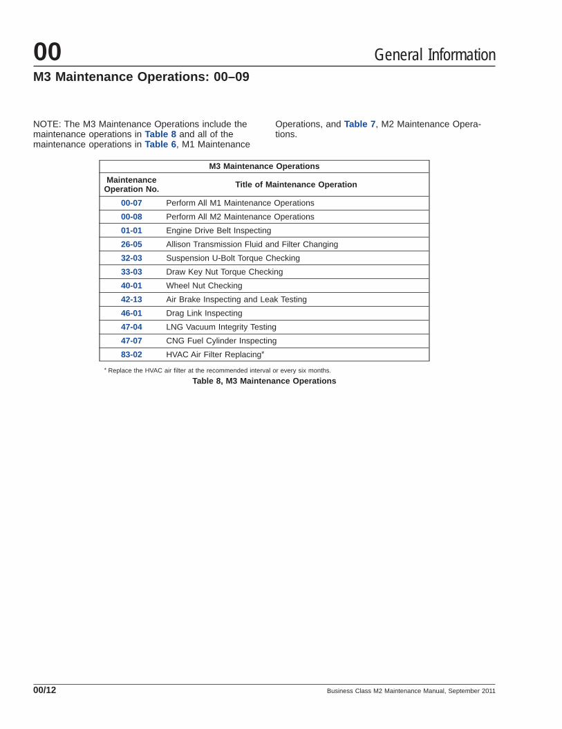
NOTE: The M3 Maintenance Operations include themaintenance operations in Table 8 and all of themaintenance operations in Table 6 , M1 Maintenance
Operations, and Table 7 , M2 Maintenance Opera-tions.
M3 Maintenance Operations
MaintenanceOperation No. Title of Maintenance Operation
00-07 Perform All M1 Maintenance Operations
00-08 Perform All M2 Maintenance Operations
01-01 Engine Drive Belt Inspecting
26-05 Allison Transmission Fluid and Filter Changing
32-03 Suspension U-Bolt Torque Checking
33-03 Draw Key Nut Torque Checking
40-01 Wheel Nut Checking
42-13 Air Brake Inspecting and Leak Testing
46-01 Drag Link Inspecting
47-04 LNG Vacuum Integrity Testing
47-07 CNG Fuel Cylinder Inspecting
83-02 HVAC Air Filter Replacing*
* Replace the HVAC air filter at the recommended interval or every six months.
Table 8, M3 Maintenance Operations
General Information00M3 Maintenance Operations: 00–09
Business Class M2 Maintenance Manual, September 201100/12

NOTE: The M4 Maintenance Operations include themaintenance operations in Table 9 and all of themaintenance operations in Table 6 , M1 Maintenance
Operations, Table 7 , M2 Maintenance Operations,and Table 8 , M3 Maintenance Operations.
M4 Maintenance Operations
MaintenanceOperation No. Title of Maintenance Operation
00-07 Perform All M1 Maintenance Operations
00-08 Perform All M2 Maintenance Operations
00-09 Perform All M3 Maintenance Operations
01-02 Engine Support Fastener Checking
09-01 Air Cleaner Element Inspecting and Replacing
15-01 Alternator, Battery, and Starter Checking
20-02 Radiator Pressure Flushing and Coolant Changing
20-04 Hybrid Electric System Coolant Changing
31-01 Frame Fastener Torque Checking
35-03 Axle Lubricant Changing and Magnetic Plug Cleaning
42-03 Governor D–2A Checking
46-02 Power Steering Fluid Changing
47-02 Fuel/Water Separator Element Replacing
60-01 Mirror Folding Check
Table 9, M4 Maintenance Operations
General Information 00M4 Maintenance Operations: 00–10
Business Class M2 Maintenance Manual, September 2011 00/13

NOTE: The M5 Maintenance Operations include themaintenance operations in Table 10 and all of themaintenance operations in Table 6 , M1 Maintenance
Operations, Table 7 , M2 Maintenance Operations,Table 8 , M3 Maintenance Operations, and Table 9 ,M4 Maintenance Operations.
M5 Maintenance Operations
MaintenanceOperation No. Title of Maintenance Operation
00-07 Perform All M1 Maintenance Operations
00-08 Perform All M2 Maintenance Operations
00-09 Perform All M3 Maintenance Operations
00-10 Perform All M4 Maintenance Operations
25-04 Clutch Hydraulic Fluid Changing
26-06 Mercedes-Benz Transmission Fluid Changing and Magnetic PlugCleaning
26-07 Mercedes-Benz Transmission Leak Checking
42-02 Bendix AD-9 Air Dryer Desiccant Replacing
42-05 Bendix AD-IP Air Dryer Desiccant Replacing
42-09 Bendix AD-IS Air Dryer Desiccant Replacing
42-14 Foot-Control Valve, E6, Inspecting and Lubricating
46-06 Power Steering Filter Changing
49-03 CAT CGI Bellows Replacement
Table 10, M5 Maintenance Operations
General Information00M5 Maintenance Operations: 00–11
Business Class M2 Maintenance Manual, September 201100/14

Table 11 , MOP 00-12, lists the lubrication and fluidlevel check maintenance operations that must beperformed at the M1 Maintenance Interval.
MOP 00-12, M1 Lubrication and Fluid Level Check
MaintenanceOperation No. Title of Maintenance Operation
25-01 Eaton Fuller Clutch Release Bearing Lubricating
25-02 Eaton Fuller Clutch Release Cross-Shaft Lubricating
25-03 Clutch Hydraulic Fluid Level Checking
26-01 Manual Transmission Fluid Level Checking
31-03 Fifth Wheel Lubricating
31-04 Trailer Electrical Connector Lubricating
32-02 Suspension Lubricating
33-01 Kingpin Lubricating
33-03 Tie Rod End Lubricating
35-01 Axle Lubricant Level Checking
41-02 Driveline Lubricating
42-06 Haldex and Gunite Slack Adjuster Lubricating
42-08 Meritor Slack Adjuster Lubricating
46-03 Power Steering Fluid Level Inspecting
46-04 Power Steering Gear Lubricating
46-05 Drag Link Lubricating
72-01 Door Seals Lubricating
88-01 Hood Rear Support Lubrication
Table 11, MOP 00-12, M1 Lubrication and Fluid Level Check
General Information 00M1 Lubrication and Fluid Level Check: 00–12
Business Class M2 Maintenance Manual, September 2011 00/15
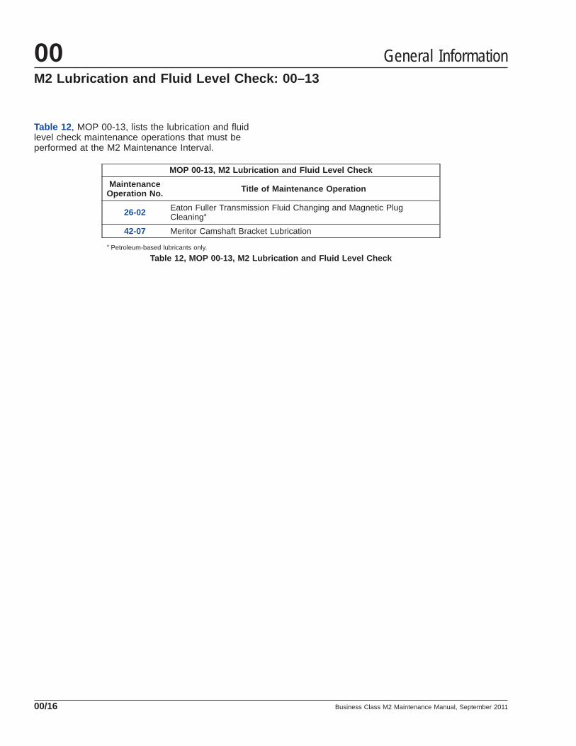
Table 12 , MOP 00-13, lists the lubrication and fluidlevel check maintenance operations that must beperformed at the M2 Maintenance Interval.
MOP 00-13, M2 Lubrication and Fluid Level Check
MaintenanceOperation No. Title of Maintenance Operation
26-02 Eaton Fuller Transmission Fluid Changing and Magnetic PlugCleaning*
42-07 Meritor Camshaft Bracket Lubrication
* Petroleum-based lubricants only.
Table 12, MOP 00-13, M2 Lubrication and Fluid Level Check
General Information00M2 Lubrication and Fluid Level Check: 00–13
Business Class M2 Maintenance Manual, September 201100/16

Noise Emission Controls
Federal Law, Part 205:Transportation Equipment NoiseEmission ControlsPart 205, Transportation Equipment Noise EmissionControls, requires the vehicle manufacturer to furnisheach new vehicle with written instructions for theproper maintenance, use, and repair of the vehicleby the ultimate purchaser to provide reasonable as-surance of the elimination or minimization of noiseemission degradation throughout the life of the ve-hicle. In compliance with the law, the Noise EmissionControl Systems maintenance located in each appli-cable group within this manual, in conjunction withthe vehicle workshop manual, provides these instruc-tions to owners.
Recommendations forReplacement PartsReplacement parts used for maintenance or repair ofnoise emission control systems should be genuineFreightliner parts. If other than genuine Freightlinerparts are used for replacement or repair of compo-nents affecting noise emission control, the ownershould be sure that such parts are warranted by theirmanufacturer to be equivalent to genuine Freightlinerparts in performance and durability.
Freightliner Noise EmissionsWarrantyRefer to the vehicle owner’s warranty informationbook for warranty information concerning noise emis-sion control systems.
Tampering With the NoiseControl System is ProhibitedFederal law prohibits the following acts or the caus-ing thereof:
1. The removal or rendering inoperative by any per-son other than for purposes of maintenance, re-pair, or replacement, of any device or element ofdesign incorporated into any new vehicle for thepurpose of noise control prior to its sale or deliv-ery to the ultimate purchaser or while it is in use,
2. The use of the vehicle after such device or ele-ment of design has been removed or renderedinoperative by any person.
Among those acts presumed to constitute tamperingare the acts listed below:
1. Removal of engine noise-deadening panels, in-cluding cab or hood liners.
2. Removal of or rendering inoperative the enginespeed governor so as to allow engine speed toexceed the manufacturer’s specifications.
3. Removal of or rendering inoperative the fanclutch, including bypassing the control on anythermostatic fan drive to cause it to operate con-tinuously.
4. Removal of the fan shroud.
5. Removal of or rendering inoperative exhaust sys-tem components, including exhaust pipe clamp-ing.
6. Removal of air intake system components.
General Information 00Noise Emission Controls: 00–15
Business Class M2 Maintenance Manual, September 2011 00/17

Verification of Inspections LogThe "Verification of Inspections Log" should be filledout each time the vehicle’s noise emission controlsare maintained or repaired.
Verification of Inspections Log, Group 20
Verification of Inspections Log, Group 20, Engine Cooling/Radiator
Date Mileage Repair Description Cost Repair Facility
Verification of Inspections Log, Group 49
Verification of Inspections Log, Group 49, Exhaust
Date Mileage Repair Description Cost Repair Facility
General Information00Verification of Inspections Log: 00–16
Business Class M2 Maintenance Manual, September 201100/18

Metric/U.S. Customary Conversions
When You Know U.S.Customary
MultiplyBy To Get Metric When You
Know MetricMultiply
By To Get U.S. Customary
Length
inches (in) 25.4 millimeters (mm) 0.03937 inches (in)
inches (in) 2.54 centimeters (cm) 0.3937 inches (in)
feet (ft) 0.3048 meters (m) 3.281 feet (ft)
yards (yd) 0.9144 meters (m) 1.094 yards (yd)
miles (mi) 1.609 kilometers (km) 0.6215 miles (mi)
Area
square inches (in2) 645.16 square millimeters (mm2) 0.00155 square inches (in2)
square inches (in2) 6.452 square centimeters (cm2) 0.155 square inches (in2)
square feet (ft2) 0.0929 square meters (m2) 10.764 square feet (ft2)
Volume
cubic inches (in3) 16387.0 cubic millimeter (mm3) 0.000061 cubic inches (in3)
cubic inches (in3) 16.387 cubic centimeters (cm3) 0.06102 cubic inches (in3)
cubic inches (in3) 0.01639 liters (L) 61.024 cubic inches (in3)
fluid ounces (fl oz) 29.54 milliliters (mL) 0.03381 fluid ounces (fl oz)
pints (pt) 0.47318 liters (L) 2.1134 pints (pt)
quarts (qt) 0.94635 liters (L) 1.0567 quarts (qt)
gallons (gal) 3.7854 liters (L) 0.2642 gallons (gal)
cubic feet (ft3) 28.317 liters (L) 0.03531 cubic feet (ft3)
cubic feet (ft3) 0.02832 cubic meters (m3) 35.315 cubic feet (ft3)
Weight/Force
ounces (av) (oz) 28.35 grams (g) 0.03527 ounces (av) (oz)
pounds (av) (lb) 0.454 kilograms (kg) 2.205 pounds (av) (lb)
U.S. tons (t) 907.18 kilograms (kg) 0.001102 U.S. tons (t)
U.S. tons (t) 0.90718 metric tons (t) 1.1023 U.S. tons (t)
Torque/Work Force
inch-pounds (lbf·in) 11.298 Newton centimeters (N·cm) 0.08851 inch pounds (lbf·in)
foot-pounds (lbf·ft) 1.3558 Newton meters (N·m) 0.7376 foot pounds (lbf·ft)
Pressure/Vacuum
inches of mercury (inHg) 3.37685 kilo Pascals (kPa) 0.29613 inches of mercury (inHg)
pounds per square inch (psi) 6.895 kilo Pascals (kPa) 0.14503 pounds per square inch (psi)
Table 13, Metric/U.S. Customary Conversions
General Information 00Metric/U.S. Customary and Temperature
Conversions: 00–17
Business Class M2 Maintenance Manual, September 2011 00/19

Temperature Conversions
When You Know Subtract ThenDivide By To Get When You
KnowMultiply
ByThenAdd To Get
degrees Fahrenheit (°F) 32 1.8 degrees Celsius (°C) 1.8 32 degrees Fahrenheit (°F)
Table 14, Temperature Conversions
General Information00Metric/U.S. Customary and TemperatureConversions: 00–17
Business Class M2 Maintenance Manual, September 201100/20

Torque Values for U.S. Customary Thread Fasteners With Lubricated * or Plated Threads †
ThreadDiameter–
Pitch
Regular Hex Flanged
Grade 5Bolt
Grade 5 orB Nut
Grade 8 or8.2 Bolt
Grade 8 orC Nut
Grade 5Bolt
Grade BNut
Grade 8 or8.2 Bolt
Grade GNut
Torque: lbf·ft (N·m) Torque: lbf·ft (N·m) Torque: lbf·ft (N·m) Torque: lbf·ft (N·m)
1/4–20
f230002 f230003 f230004 f230005f230006 f230007 f230008 f230009
7 (9) 8 (11) 6 (8) 10 (14)
1/4–28 8 (11) 9 (12) 7 (9) 12 (16)
5/16–18 15 (20) 16 (22) 13 (18) 21 (28)
5/16–24 16 (22) 17 (23) 14 (19) 23 (31)
3/8–16 26 (35) 28 (38) 23 (31) 37 (50)
3/8–24 30 (41) 32 (43) 25 (34) 42 (57)
7/16–14 42 (57) 45 (61) 35 (47) 60 (81)
7/16–20 47 (64) 50 (68) 40 (54) 66 (89)
1/2–13 64 (87) 68 (92) 55 (75) 91 (123)
1/2–20 72 (98) 77 (104) 65 (88) 102 (138)
9/16–12 92 (125) 98 (133) 80 (108) 130 (176)
9/16–18 103 (140) 110 (149) 90 (122) 146 (198)
5/8–11 128 (173) 136 (184) 110 (149) 180 (244)
5/8–18 145 (197) 154 (209) 130 (176) 204 (277)
3/4–10 226 (306) 241 (327) 200 (271) 320 (434)
3/4–16 253 (343) 269 (365) 220 (298) 357 (484)
7/8–9 365 (495) 388 (526) 320 (434) 515 (698)
7/8–14 402 (545) 427 (579) 350 (475) 568 (770)
1–8 — 582 (789) — —
1–12 — 637 (863) — —
1–14 — 652 (884) — —
* Freightliner recommends that all plated and unplated fasteners be coated with oil before installation.† Use these torque values if either the bolt or nut is lubricated or plated (zinc-phosphate conversion-coated, cadmium-plated, or waxed).
Table 15, Torque Values for U.S. Customary Thread Fasteners With Lubricated or Plated Threads
General Information 00Torque Specifications: 00–18
Business Class M2 Maintenance Manual, September 2011 00/21

Torque Values for U.S. Customary Thread Fasteners With Dry (Unlubricated) * Plain (Unplated) Threads †
ThreadDiameter–
Pitch
Regular Hex Flanged
Grade 5 Bolt Grade 5 or BNut
Grade 8 or 8.2Bolt
Grade 8 or CNut
Grade 8 or 8.2Bolt Grade G Nut
Torque: lbf·ft (N·m) Torque: lbf·ft (N·m) Torque: lbf·ft (N·m)
1/4–20
f230002 f230003 f230004 f230005 f230008 f230009
8 (11) 10 (14) —
1/4–28 9 (12) 12 (16) —
5/16–18 15 (20) 22 (30) 22 (30)
5/16–24 17 (23) 25 (34) —
3/8–16 28 (38) 40 (54) 40 (54)
3/8–24 31 (42) 45 (61) —
7/16–14 45 (61) 65 (88) 65 (88)
7/16–20 50 (68) 70 (95) —
1/2–13 70 (95) 95 (129) 95 (129)
1/2–20 75 (102) 110 (149) —
9/16–12 100 (136) 140 (190) 140 (190)
9/16–18 110 (149) 155 (210) —
5/8–11 135 (183) 190 (258) 190 (258)
5/8–18 155 (210) 215 (292) —
3/4–10 240 (325) 340 (461) 340 (461)
3/4–16 270 (366) 380 (515) —
7/8–9 385 (522) 540 (732) —
7/8–14 425 (576) 600 (813) —
1–8 580 (786) 820 (1112) —
1–12 635 (861) 900 (1220) —
1–14 650 (881) 915 (1241) —
* Threads may have residual oil, but will be dry to the touch.† Male and female threads (bolt and nut) must both be unlubricated and unplated. If either is plated or lubricated, use Table 15 . Freightliner recommends that
all plated and unplated fasteners be coated with oil before installation.
Table 16, Torque Values for U.S. Customary Thread Fasteners With Dry (Unlubricated) Plain (Unplated) Threads
General Information00Torque Specifications: 00–18
Business Class M2 Maintenance Manual, September 201100/22
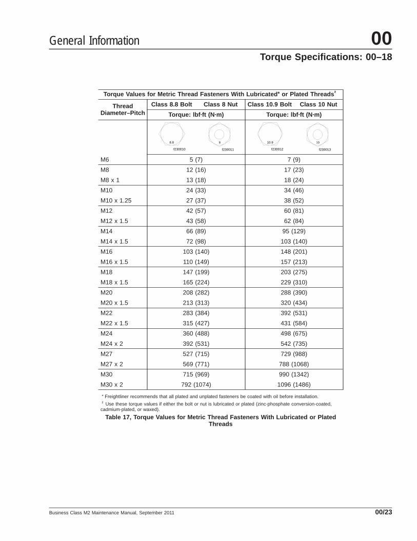
Torque Values for Metric Thread Fasteners With Lubricated * or Plated Threads †
ThreadDiameter–Pitch
Class 8.8 Bolt Class 8 Nut Class 10.9 Bolt Class 10 Nut
Torque: lbf·ft (N·m) Torque: lbf·ft (N·m)
M6
f230010
8.8
f230011
8
f230012
10.9
f230013
10
5 (7) 7 (9)
M8 12 (16) 17 (23)
M8 x 1 13 (18) 18 (24)
M10 24 (33) 34 (46)
M10 x 1.25 27 (37) 38 (52)
M12 42 (57) 60 (81)
M12 x 1.5 43 (58) 62 (84)
M14 66 (89) 95 (129)
M14 x 1.5 72 (98) 103 (140)
M16 103 (140) 148 (201)
M16 x 1.5 110 (149) 157 (213)
M18 147 (199) 203 (275)
M18 x 1.5 165 (224) 229 (310)
M20 208 (282) 288 (390)
M20 x 1.5 213 (313) 320 (434)
M22 283 (384) 392 (531)
M22 x 1.5 315 (427) 431 (584)
M24 360 (488) 498 (675)
M24 x 2 392 (531) 542 (735)
M27 527 (715) 729 (988)
M27 x 2 569 (771) 788 (1068)
M30 715 (969) 990 (1342)
M30 x 2 792 (1074) 1096 (1486)
* Freightliner recommends that all plated and unplated fasteners be coated with oil before installation.† Use these torque values if either the bolt or nut is lubricated or plated (zinc-phosphate conversion-coated,
cadmium-plated, or waxed).
Table 17, Torque Values for Metric Thread Fasteners With Lubricated or PlatedThreads
General Information 00Torque Specifications: 00–18
Business Class M2 Maintenance Manual, September 2011 00/23

Title of Maintenance Operation (MOP) MOP Number
Engine Drive Belt Inspecting. . . . . . . . . . . . . . . . . . . . . . . . . . . . . . . . . . . . . . . . . . . . . . . . . . . . . . . . . . 01–01
Engine Support Fastener Checking. . . . . . . . . . . . . . . . . . . . . . . . . . . . . . . . . . . . . . . . . . . . . . . . . . . . . 01–02
Engine 01Index, Alphabetical
Business Class M2 Maintenance Manual, January 2007

01–01 Engine Drive BeltInspecting
Worn or loose drive belts may cause premature pul-ley bearing failure or engine overheating. Too muchor too little tension on the belt may result in exces-sive or premature belt wear. Replace the enginedrive belt if any conditions described under VisualInspection are found.
Visually inspect all drive belts, then perform the belttension inspection. To inspect a belt, gently twist thebelt to view the belt sidewalls and the underside ofthe belt. When replacing a matched set of belts, al-ways replace both belts at the same time. Matchedbelts must be from the same manufacturer.
Visual InspectionFor examples of drive belt conditions, see Fig. 1 .
1. Inspect the belt for glazing. Shiny sidewalls areevidence of glazing, which is caused by frictioncreated when a loose belt slips in the pulleys. Itcan also be caused by oil or grease contamina-tion on the pulleys.
2. Check for tensile breaks or breaks in the cordbody. Cuts in a belt are usually caused by for-eign material in the pulley or by prying or forcingthe belt during removal or installation.
3. Check the belt for ply separation. Oil, grease, orbelt dressing can cause the belt to fall apart inlayers. Repair any oil or coolant leaks that areaffecting the belts before replacing the drivebelts. Do not use belt dressing on any belt.
4. Check for uneven ribs on serpentine (poly-V)belts. Foreign material in the pulley will erode theundercord ribs causing the belt to lose its grip-ping power.
5. Check the belt for a jagged or streaked sidewall.Jagged or streaked sidewalls are the result of
f150010b07/12/2001
1 2
3 4
5 6
1. Glazing2. Tensile Break
3. Separating Layers4. Uneven Ribs
5. Streaked Sidewalls6. Cracks
Fig. 1, Drive Belt Replacement Conditions
Engine 01
Business Class M2 Maintenance Manual, January 2007 01/1
foreign material, such as sand or gravel, in thepulley, or a rough pulley surface.
6. Check the drive belts for cracks. Small, irregularcracks are usually indication of an old belt.
7. Visually inspect the pulleys for excessive play orwobble. Excessive play or wobble indicates afailure of the pulley bearing. Check for beltsquealing or squeaking. Replace the bearings asnecessary.
NOTE: If it is difficult to distinguish the locationof a supposed bearing noise, obtain a stetho-scope and place it on the component beingchecked, not the pulley, to isolate the area fromoutside interference.
8. Inspect all pulleys for foreign material, oil, orgrease in the grooves.
If the engine drive belt needs to be replaced, seeGroup 01 of the Business Class® M2 WorkshopManual.
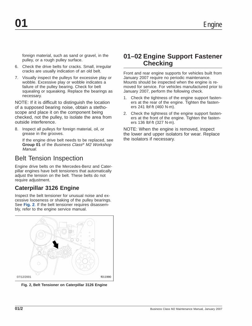
Belt Tension InspectionEngine drive belts on the Mercedes-Benz and Cater-pillar engines have belt tensioners that automaticallyadjust the tension on the belt. These belts do notrequire adjustment.
Caterpillar 3126 EngineInspect the belt tensioner for unusual noise and ex-cessive looseness or shaking of the pulley bearings.See Fig. 2 . If the belt tensioner requires disassem-bly, refer to the engine service manual.
01–02 Engine Support FastenerChecking
Front and rear engine supports for vehicles built fromJanuary 2007 require no periodic maintenance.Mounts should be inspected when the engine is re-moved for service. For vehicles manufactured prior toJanuary 2007, perform the following check.
1. Check the tightness of the engine support fasten-ers at the rear of the engine. Tighten the fasten-ers 241 lbf·ft (460 N·m).
2. Check the tightness of the engine support fasten-ers at the front of the engine. Tighten the fasten-ers 136 lbf·ft (327 N·m).
NOTE: When the engine is removed, inspectthe lower and upper isolators for wear. Replacethe isolators if necessary.
07/12/2001 f011990
Fig. 2, Belt Tensioner on Caterpillar 3126 Engine
Engine01
Business Class M2 Maintenance Manual, January 200701/2
Title of Maintenance Operation (MOP) MOP Number
Air Cleaner Element Inspection and Replacement . . . . . . . . . . . . . . . . . . . . . . . . . . . . . . . . . . . . . . . . . . 09–01
Air Intake 09Index, Alphabetical
Business Class M2 Maintenance Manual, November 2009
09–01 Air Cleaner ElementInspection andReplacement
Restriction of air flow through the air cleaner elementis measured at the tap in the air cleaner outlet.Check the restriction indicator at the air cleaner or inthe cab if the vehicle is equipped with a dash-mounted restriction gauge.
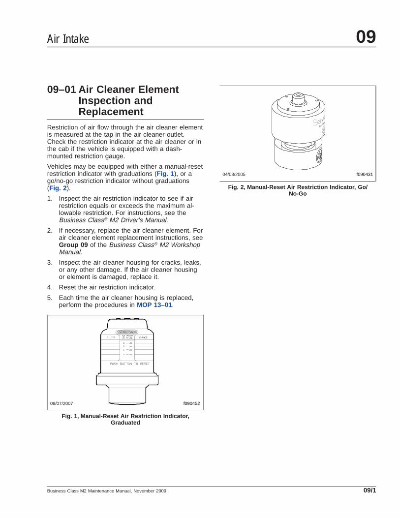
Vehicles may be equipped with either a manual-resetrestriction indicator with graduations (Fig. 1 ), or ago/no-go restriction indicator without graduations(Fig. 2 ).
1. Inspect the air restriction indicator to see if airrestriction equals or exceeds the maximum al-lowable restriction. For instructions, see theBusiness Class® M2 Driver’s Manual.
2. If necessary, replace the air cleaner element. Forair cleaner element replacement instructions, seeGroup 09 of the Business Class® M2 WorkshopManual.
3. Inspect the air cleaner housing for cracks, leaks,or any other damage. If the air cleaner housingor element is damaged, replace it.
4. Reset the air restriction indicator.
5. Each time the air cleaner housing is replaced,perform the procedures in MOP 13–01.
08/07/2007 f090452
Fig. 1, Manual-Reset Air Restriction Indicator,Graduated
04/08/2005 f090431
Fig. 2, Manual-Reset Air Restriction Indicator, Go/No-Go
Air Intake 09
Business Class M2 Maintenance Manual, November 2009 09/1

Title of Maintenance Operation (MOP) MOP Number
Air Compressor Inspecting . . . . . . . . . . . . . . . . . . . . . . . . . . . . . . . . . . . . . . . . . . . . . . . . . . . . . . . . . . . 13–01
Air Compressor 13Index, Alphabetical
Business Class M2 Maintenance Manual, December 2001

13–01 Air CompressorInspecting
1. Inspect the air compressor intake adaptors atboth ends of the line for physical damage. Re-place the adaptors if necessary.
2. Inspect the air intake line, oil supply and returnlines, and coolant supply and return lines for tightconnections. Tighten the connections and re-place the lines if needed.
3. Check the cooling fins on the air compressorcrankcase. Clean the fins if they are clogged withdebris.
Air Compressor 13
Business Class M2 Maintenance Manual, December 2001 13/1

Title of Maintenance Operation (MOP) MOP Number
Alternator, Battery, and Starter Checking. . . . . . . . . . . . . . . . . . . . . . . . . . . . . . . . . . . . . . . . . . . . . . . . . 15–01
Alternators and Starters 15Index, Alphabetical
Business Class M2 Maintenance Manual, January 2009
15–01 Alternator, Battery, andStarter Checking
WARNINGBatteries release explosive gas as a by-product oftheir chemical activity. Do not smoke when work-ing around batteries. Put out all flames and re-move any source of sparks or intense heat. Makesure the battery compartment is completelyvented before disconnecting or connecting thebattery cables.
Battery acid is extremely harmful if splashed inthe eyes or on the skin. Always wear a face shieldand protective clothing when working around bat-teries.
Damaged, chafed, or kinked wiring can causeelectrical short-circuits and lead to fires, causingproperty damage, injury, or death. Clean, inspect,and maintain wiring and connections carefully.
1. Check the tightness of the alternator bracket fas-teners; tighten the fasteners as needed. Fortorque values, see Group 15 of the BusinessClass® M2 Workshop Manual.
2. See Group 01 for belt tension specifications.Check the alternator drive belt tension, using atension gauge at the belt’s longest span. Someengines are equipped with more than one alter-nator belt; check all of them for correct tension.Adjust the belt tension if necessary.
Engines equipped with a serpentine or poly-Vbelt have automatic belt tensioners, and do notrequire belt tension inspection.
3. Check that all electrical connections at the alter-nator and starter are clean. Clean and tighten allcharging system electrical connections includingthe connections at the starter B terminal andground terminal, and where the alternator charg-ing cable terminates.
Trace and inspect all wiring and cables con-nected to:
• Alternator
• Starter and depopulation studs
• Batteries
• Magnetic switch
• Cab
• Jump-start studs
• Battery isolation relays
• Battery shutoff switches
4. Check wires and cables for wear, chafing, kinks,discolored insulation, or loose clamps or ties.Find the cause of any problems and repair, re-place, and reroute wires and clamps as neces-sary.
5. Check the alternator wiring for missing insulation,kinks, and heat damage. Replace or repair asneeded.
6. On the bundled cable that runs from the batteriesto the starter, ensure that tie straps are installedat least every 12 inches (300 mm). Replace anymissing tie straps, and add tie straps wherespacing between them exceeds 12 inches (300mm).
7. Ensure that all cables have sufficient slack toallow for engine movement, and that there is nopressure on any wiring connectors.
8. If any convoluted tubing is damaged, check thewiring inside it. Replace any damaged or missingconvoluted tubing.
9. Clean the cable connector terminals with a wirebrush. See Group 54 of the Business Class® M2Workshop Manual for troubleshooting instruc-tions, and for adjustment, repair, or replacementinstructions.
9.1 Clean and tighten the battery groundcable, terminal, and clamps.
9.2 Inspect the retainer assembly (or batteryhold-downs) and the battery box. Replaceworn or damaged parts. Remove any cor-rosion with a wire brush, and wash with aweak solution of baking soda and water.Rinse with clean water and dry. To pre-vent rusting, paint the retainer assembly.
9.3 Check for and remove any foreign objectssuch as stones, bolts, or nuts, from thebattery box.
9.4 After cleaning, connect the cables to thebatteries, and tighten them to the torquespecifications listed on the battery, gener-ally 10 to 15 lbf·ft (14 to 20 N·m).
Alternators and Starters 15
Business Class M2 Maintenance Manual, January 2009 15/1

9.5 Coat the battery terminals with dielectricgrease.
10. Check the terminals on the battery shut-offswitch and the magnetic switch. Make sure theterminal connections are clean and tight. Coatthe terminal connections with dielectric redenamel after cleaning.
Alternators and Starters15
Business Class M2 Maintenance Manual, January 200915/2

Title of Maintenance Operation (MOP) MOP Number
Fan Drive Inspecting (Noise Emission Control) . . . . . . . . . . . . . . . . . . . . . . . . . . . . . . . . . . . . . . . . . . . . 20–03
Hybrid Electric System Coolant Changing . . . . . . . . . . . . . . . . . . . . . . . . . . . . . . . . . . . . . . . . . . . . . . . . 20–04
Radiator Cap Inspecting. . . . . . . . . . . . . . . . . . . . . . . . . . . . . . . . . . . . . . . . . . . . . . . . . . . . . . . . . . . . . 20–01
Radiator Pressure Flushing and Coolant Changing . . . . . . . . . . . . . . . . . . . . . . . . . . . . . . . . . . . . . . . . . 20–02
Engine Cooling/Radiator 20Index, Alphabetical
Business Class M2 Maintenance Manual, July 2009

20–01 Radiator Cap Inspecting
WARNINGDo not remove or loosen the radiator cap until theengine and cooling system have completelycooled. Use extreme care when removing the cap.A sudden release of pressure from removing thecap prior to the system cooling can result in asurge of scalding coolant that could cause seri-ous personal injury.
CAUTIONThe radiator cap currently installed may not be thesame one installed when the vehicle was built. Ifthe radiator cap must be replaced, make sure thatit is the correct cap for the cooling system of thevehicle. Because the radiator cap pressure ratingaffects the operating temperature of the engine,installing an improperly rated radiator cap mayhave adverse effects on the cooling system, andengine operating temperatures. This could causepremature engine wear or damage.
1. Using a radiator-cap tester, check the pressurecap to see if it maintains pressure to within 10percent of the pressure rating marked on thecap. If it doesn’t, replace the cap. Make sure thatthe replacement radiator cap is correctly rated forthe cooling system of the vehicle.
2. There is a second valve in the radiator cap thatopens under vacuum. This prevents the collapseof hoses and other parts that are not internallysupported when the system cools. Inspect thevacuum-relief valve to be sure it is not stuck.
3. Make sure that the cap seals properly on thecoolant filler neck seat, and that the radiator capgasket is not damaged. On vehicles withscrew-on caps with O-rings, make sure that theO-ring is not cracked or deteriorated. Replacethe cap if the gasket shows deterioration or dam-age.
20–02 Radiator PressureFlushing and CoolantChanging
NOTE: For additional instructions on cleaningand flushing the cooling system, see the enginemaintenance and operation manual.
WARNINGDrain the coolant only when the coolant and en-gine are cool. Draining it when these are hot couldcause severe personal injury due to scalding.
1. Drain the radiator, as follows.
1.1 Place a large container under the radia-tor.
1.2 Remove the surge tank cap.
1.3 Open the petcock at the bottom of theradiator to drain the engine coolant.
2. Disconnect the radiator inlet and outlet hose con-nections.
3. Flush the radiator, as follows.
3.1 Attach a flushing gun nozzle to the radia-tor outlet.
3.2 Add water to the radiator until it is full.
CAUTIONWhen flushing the radiator, do not apply morethan 20 psi (138 kPa) air pressure. Excessive pres-sure can damage the radiator or heater core.
3.3 Apply no more than 20 psi (138 kPa) airpressure intermittently to help dislodgesediment buildup in the core.
4. Drain the radiator, then flush the radiator untilclean water flows from it. Remove the flushinggun.
5. Close the petcock.
6. Using clamps, connect the hoses to the radiator.Torque the clamps 33 to 38 lbf·in (370 to 430N·cm).
IMPORTANT: On vehicles with EPA07 compliantengines, the coolant capacity varies dependingon the engine and accessory installation. After
Engine Cooling/Radiator 20
Business Class M2 Maintenance Manual, July 2009 20/1

servicing the cooling system, always verify thatthe coolant level is between the MIN and MAXlines on the surge tank.
7. Fill the radiator with coolant. Use a mixture of 50percent water and 50 percent corrosion-inhibitingantifreeze to protect the engine to –34°F (–37°C)year round.
See Table 1 for engine cooling system capaci-ties.
See Table 2 for approved antifreezes.
Coolant Capacities (pre-EPA07 engines)
Engine Make and Model Coolant Volume:quarts (liters)
Caterpillar 3126 35 (33.1)
MBE904 32 (30.3)
MBE906 37 (35)
Table 1, Coolant Capacities (pre-EPA07 engines)
Approved Coolants
Coolant Manufacturer Coolant Designation *
Texaco JC04 Antifreeze
Van Waters and RogersLtd. (Canada)
Diesel Antifreeze No. 6038
* Freightliner-approved antifreeze must meet one of the following condi-tions: A. Ethylene glycol solution that meets GM 6038–M Engineering Stan-dards. B. Ethylene glycol solution that has less than 0.1% anhydrous so-dium metasilicate and meets either GM 1825–M or GM 1899–MEngineering Standards.
Table 2, Approved Coolants
20–03 Fan Drive Inspecting(Noise EmissionControl)
Horton Advantage® Fan Clutch1. Check the fan for loose rivets and missing
weights. Check for bent, cracked, or missingblades. Tighten loose components. Replace thefan drive if necessary.
2. Check for adequate clearance between the fanand the fan shroud or other engine compartmentcomponents in both the engaged mode and the
disengaged mode. If the clearance is not ad-equate, make the necessary adjustments.
3. Check the fan belt condition and the belt align-ment. Replace or correct as necessary.
Horton HT650 Fan DriveCheck for friction facing wear condition. Replacewhen worn to 1/16-inch (1.5-mm) thick, when oilspotted, or when burn marks are visible.
Kysor K22RA, K22FA, andK26RA Fan Drives1. Check the fan for missing, cracked, chipped, or
damaged blades. Tighten loose components. Re-place damaged fans if necessary.
2. Check for adequate clearance around the fan.The fan should be centered in the shroud to pre-vent contact between the fan and the shroud.
3. Check the fan belt for proper alignment and con-dition. If the belt is worn or frayed, replace thebelt.
4. Verify the fan drive engagement. With the engineand ignition key switch off, apply at least 90 psi(620 kPa) to the clutch; the fan should rotatefreely. Remove air pressure from the clutch andthe fan should not rotate.
5. With the fan drive disengaged, check for airleaks at the front of the clutch and between theclutch and the drive hub. If an air leak is de-tected, the clutch seals and hub must be in-spected for wear or damage. If necessary, theseals of the clutch can be replaced with a Kysorrebuild kit. If inspection of the hub indicates ex-cessive wear, rebuild the hub using a hub rebuildkit from Kysor.
6. Any time the clutch is removed for repair or re-placement, the pulley hub and bearings shouldbe inspected for play, roughness, or damage.Hub bearing service kits are available fromKysor.
7. Check the lining with the System Alert Tool™. Ifthe lining is worn, install the appropriate lining kit.A lining that is prematurely worn is caused bycontrol air supply problems. Inspect and correctthe vehicle control system before placing the ve-hicle back in service.
Engine Cooling/Radiator20
Business Class M2 Maintenance Manual, July 200920/2

8. Check the air line entry and routing at the frontor rear of the fan drive. Look for cracked, dam-aged, or improperly routed air lines. Make surethe connections are tight and that there are noair leaks.
9. Check the electrical connections at the solenoidvalve. The solenoid valve is part of the air mod-ule unit (AMU), which is located on the rearcrossmember. Check the exhaust port for restric-tions. If a restriction is found, clear it.
Horton DriveMaster® Fan ClutchNOTE: If any part of the fan clutch needs to berepaired or replaced after performing the checksbelow, see Group 20 of the Business Class®
M2 Workshop Manual.
1. Disconnect the batteries at the negative termi-nals. Drain all air from the air system. Ifequipped with an air starter, drain the air starterreservoir.
WARNINGMake sure the batteries are disconnected beforechecking the fan clutch. If the engine starts duringthis procedure, the fan could engage, which couldresult in serious personal injury.
2. Inspect the electrical connections and wires tothe fan clutch solenoid. Secure the connection ifloose; replace wires and connectors if damaged.
3. Clean the fan clutch air solenoid valve filter, ifequipped.
3.1 Unscrew the fan clutch solenoid valve airfilter assembly, and remove the filter ele-ment.
3.2 Clean the filter element with cleaning sol-vent.
3.3 Using a clean, lint-free cloth, wipe off anyexcess solvent.
3.4 Reassemble the clutch valve solenoid airfilter assembly, and install it on the ve-hicle.
4. Visually check the fan for bent, cracked, or dam-aged blades. Replace if damaged. Check for ad-equate clearance between the fan and othercomponents.
5. Check the fan belt for wear, tension, and align-ment. Correct, if necessary.
6. Check for wear on the friction facing. Replacethe friction facing if it is worn to a 3/16-inch (4.8-mm) thickness or less. Also check the facing forsigns of oil contamination or burn marks. If evi-dence of oil or burn marks are found, replace thefriction facing.
7. Connect the battery cables. Start the engine, andcharge the air system to 120 psi (827 kPa).Manually engage and disengage the fan clutch.
Check the fan and the fan clutch from a dis-tance. Look for vibration, fan blade contact, fanclutch slippage, and overall fan clutch operation.
If the fan clutch does not operate correctly, seeGroup 20 of the Business Class® M2 WorkshopManual for troubleshooting and repair proce-dures.
8. With the air system charged to 120 psi (827kPa), check the fan clutch for audible air leaks,using a suitable listening device.
Check at the solenoid valve, the air filter assem-bly, and the air hoses and fittings. See Fig. 1 .Using a wet finger or a soapy water solution,check for a leak in the same areas.
9. If a leak is detected, remove the fan blade. In-stall a new seal kit. See Group 20 of theBusiness Class® M2 Workshop Manual for repairprocedures.
f20058105/30/2002
Fig. 1, Checking for Air Leaks (Horton DriveMaster)
Engine Cooling/Radiator 20
Business Class M2 Maintenance Manual, July 2009 20/3

10. Check the fan drive for discoloration or any othersigns of slipping or overheating.
NOTE: The fan clutch may slip if the air supplypressure is below 70 psi (483 kPa) or if there isa leak inside the fan clutch. Any leak must beremedied.
11. Check the fan clutch bearings.
11.1 Turn the fan in both directions and feelfor worn hub bearings.
11.2 If possible, remove the drive belt andcheck for worn sheave bearings by turn-ing the sheave in both directions.
11.3 If either the hub or sheave bearings areworn, replace them, using a Horton Drive-Master Super Kit.
For instructions and kit part number, seeGroup 20 of the Business Class® M2Workshop Manual.
20–04 Hybrid Electric SystemCoolant Changing
1. Disconnect the 12-volt vehicle batteries to isolatethe high voltage power source.
2. Drain the hybrid radiator, as follows.
2.1 Place a large container under the hybridradiator.
2.2 Remove the cap from the coolant reser-voir.
2.3 If equipped with a petcock, open it at thebottom of the hybrid radiator to drain thecoolant.
2.4 Disconnect the lower radiator hose, anddrain the remaining coolant.
2.5 Close the petcock, if equipped.
3. Install the lower radiator hose.
4. Fill the system with a coolant mixture of 50 per-cent ethylene glycol and 50 percent water.
5. Using ServiceRanger1, activate the HEV coolantpump to purge any air that may be trapped in the
system. Run the cooling pump until the airbubbles stop appearing in the reservoir tank.
6. Check the coolant level, and add coolant asneeded. The system should be filled to the midlevel of the reservoir.
1 ServiceRanger is a service and diagnostic software program available fromEaton Corporation. See the Eaton website, www.roadranger.com for moreinformation.
Engine Cooling/Radiator20
Business Class M2 Maintenance Manual, July 200920/4

Title of Maintenance Operation (MOP) MOP Number
Clutch Adjusting, Manually Adjusted Clutches . . . . . . . . . . . . . . . . . . . . . . . . . . . . . . . . . . . . . . . . . . . . . 25–05
Clutch Hydraulic Fluid Changing. . . . . . . . . . . . . . . . . . . . . . . . . . . . . . . . . . . . . . . . . . . . . . . . . . . . . . . 25–04
Clutch Hydraulic Fluid Level Checking. . . . . . . . . . . . . . . . . . . . . . . . . . . . . . . . . . . . . . . . . . . . . . . . . . . 25–03
Eaton Fuller Clutch Release Bearing Lubricating . . . . . . . . . . . . . . . . . . . . . . . . . . . . . . . . . . . . . . . . . . . 25–01
Eaton Fuller Clutch Release Cross-Shaft Lubricating. . . . . . . . . . . . . . . . . . . . . . . . . . . . . . . . . . . . . . . . 25–02
Clutch 25Index, Alphabetical
Business Class M2 Maintenance Manual, June 2006

25–01 Eaton Fuller ClutchRelease BearingLubricating
The standard clutch release bearing is sealed, anddoes not require lubrication. If the vehicle is notequipped with a maintenance-free sealed clutch re-lease bearing, lubricate the bearing as follows:
1. Park the vehicle on a level surface. Apply theparking brakes, and chock the rear tires.
2. Remove the clutch inspection plate.
NOTE: Some clutch release bearings areequipped with a lubrication extension that ex-tends outside of the clutch housing. It is notnecessary to remove the clutch inspection platewhen the lubrication extension is used.
NOTE: For lubricating the release bearing,Eaton Fuller recommends a lithium-base high-temperature grease that meets the NLGI gradeone or two specification.
3. Wipe the dirt away from the grease fitting. SeeFig. 1 . Use a low-pressure-type grease gunequipped with the recommended grease, andlubricate the bearing until excess grease purgesfrom the rear of the release bearing (toward thetransmission).
CAUTIONDo not over-lubricate the clutch release bearing.Over-lubrication could contaminate the clutch in-ternally, causing clutch slippage and prematurefailure. Do not use chassis grease or multipurposelubricants.
4. Wipe off excess grease and apply it to both theyoke finger and sleeve bushing contact points.See Fig. 2 .
5. Install the clutch inspection plate.
6. Remove the chocks.
25–02 Eaton Fuller ClutchRelease Cross-ShaftLubricating
IMPORTANT: This maintenance operation per-tains only to vehicles equipped with mechanical(not hydraulic) linkages.
The clutch release cross-shaft is equipped with twogrease fittings in the transmission clutch housing.See Fig. 3 and Fig. 4 . Wipe the dirt from the grease
f250081a05/27/93
Fig. 1, Release Bearing Grease Fitting
08/10/2009 f250444
1
2
1. Sleeve Bushing Contact Point2. Yoke Finger Contact Points
Fig. 2, Grease the Contact Points
Clutch 25
Business Class M2 Maintenance Manual, June 2006 25/1

fittings and lubricate with multipurpose chassisgrease.
25–03 Clutch Hydraulic FluidLevel Checking
WARNINGUse only approved clutch hydraulic fluid (DOT 4brake fluid) in the clutch hydraulic system. Do notmix different types of brake fluid. The wrong fluidwill damage the rubber parts of the system, caus-
ing loss of clutch function and the risk of seriouspersonal injury.
CAUTIONDo not allow the fluid level in the reservoir to gobelow the MIN line. If too much air enters, the hy-draulic system will not operate correctly, and theclutch could be damaged.
If the fluid level is below the MIN line, fill the reser-voir with DOT 4 brake fluid until the level reaches theMAX line. See Fig. 5 .
25–04 Clutch Hydraulic FluidChanging
Replace the clutch hydraulic fluid every two years toensure clutch function is reliable and correct. Use theprocedures below. Fluid replacement must be doneat an authorized Freightliner service facility.
Flushing1. Shut down the engine.
2. Apply the parking brakes, chock the front andrear tires, and raise the hood.
f250048a
1
2
10/19/93
1. Clutch Release Cross-Shaft2. Grease Fitting
Fig. 3, Cross-Shaft Grease Fitting, Left Side
f260146a05/27/93
Fig. 4, Cross-Shaft Grease Fitting, Right Side
12/10/2001
12
3
4
5
6
f250580
1. Reservoir Cap2. Reservoir3. Pedal Unit
4. Master Cylinder5. Hydraulic Hose6. Slave Cylinder
Fig. 5, Clutch Components
Clutch25
Business Class M2 Maintenance Manual, June 200625/2
WARNINGClutch hydraulic fluid (DOT 4 brake fluid) is haz-ardous. It may be a skin irritant and can causeblindness if it gets in your eyes. Always wearsafety glasses when handling clutch hydraulicfluid or bleeding hydraulic lines. If you get clutchhydraulic fluid on your skin, wash it off as soonas possible.
3. Prepare the pressure bleeding equipment ac-cording to the manufacturer’s instructions. UseDOT 4 brake fluid. Pressurize the bleed adaptorto 15 psi (103 kPa).
CAUTIONDo not spill clutch hydraulic fluid (DOT 4 brakefluid) on the cab paint. Clean it off immediately ifany is spilled. DOT 4 brake fluid can damagepaint.
4. Remove the reservoir lid and install the pressurebleed adaptor on the reservoir.
5. Pressurize the reservoir, filling the system. Openthe bleed valve on the bleed tank of the adaptor.
NOTE: A pressure bleeder hose (J-29532) anda bleed adaptor (J-35798) for the fluid reservoirare available through SPX Kent-Moore Toolsand may be used to complete the following pro-cedure. To order these parts, call Kent-Moore at1-800-328-6657.
6. Flush the hydraulic system. See Fig. 6 .
6.1 Open the bleed screw on the slave cylin-der.
6.2 Using a drain pan or other suitable con-tainer, collect the fluid that drains from theslave cylinder bleed valve, at least 0.5quarts (0.5 liters).
6.3 When all the old fluid has passed throughthe system and only new, clean fluid iscoming out, close the bleed screw.
7. Check the fluid level in the reservoir and bleedthe system according to the procedures underthe heading "Bleeding the Clutch." See Fig. 7 .
Bleeding the Clutch1. Remove the cap from the bleed valve. Install a
transparent drain hose on the bleed valve of theslave cylinder.
2. Open the slave cylinder bleed screw. Observethe flow of clutch hydraulic fluid through the drainhose. When bubbles no longer appear in thefluid, close the slave cylinder bleed screw.
3. Disconnect the transparent hose. Tighten thebleed screw 88 lbf·in (1000 N·cm) and install thecap on the slave cylinder bleed valve.
4. Close the valve on the bleed tank of the pres-sure bleed adaptor. Remove the pressure bleedadaptor.
5. Check the fluid level in the reservoir. If neces-sary, add or remove clutch hydraulic fluid to bringthe fluid level to the MAX line. Install the reser-voir lid.
CAUTIONWhen removing fluid from the reservoir, use aclean tool that is used only for brake fluid. Usinga tool contaminated with oil or chemical residuewill destroy hydraulic system parts and cause thesystem to malfunction.
6. Depress the clutch pedal a few times. Thereshould be resistance over the full pedal stroke.
7. Check the entire system for leaks. Tighten theconnections between the components if neces-sary. Check the fluid level in the reservoir again.
8. Make sure the reservoir lid is tight.
9. Lower the hood and remove the chocks from thefront and rear tires.
25–05 Clutch Adjusting,Manually AdjustedClutches
NOTE: This procedure is only required for ve-hicles equipped with non-synchronized transmis-sions and manually adjusted clutches.
Release bearing travel is the clearance between therear surface of the release bearing housing and theforward surface of the clutch brake disc. This dis-
Clutch 25
Business Class M2 Maintenance Manual, June 2006 25/3

tance must be maintained between 1/2 and 9/16 inch(12.7 and 14.3 mm).
1. Remove the clutch inspection cover from the bellhousing. See Fig. 8 .
12/11/2001 f250582
123
4
5
6
7
8
9
10
123
1. Clamp-Mounting Bolt, 1/4–202. Plated Steel Washer3. Locknut, 1/4–204. Bell Housing Standoff Bracket5. Slave Cylinder Standoff Bracket
6. Hydraulic Hose7. Slave Cylinder8. Bleed Valve9. Bell Housing10. Slave Cylinder Mounting Capscrew, M8
Fig. 6, Clutch Slave Cylinder
Clutch25
Business Class M2 Maintenance Manual, June 200625/4
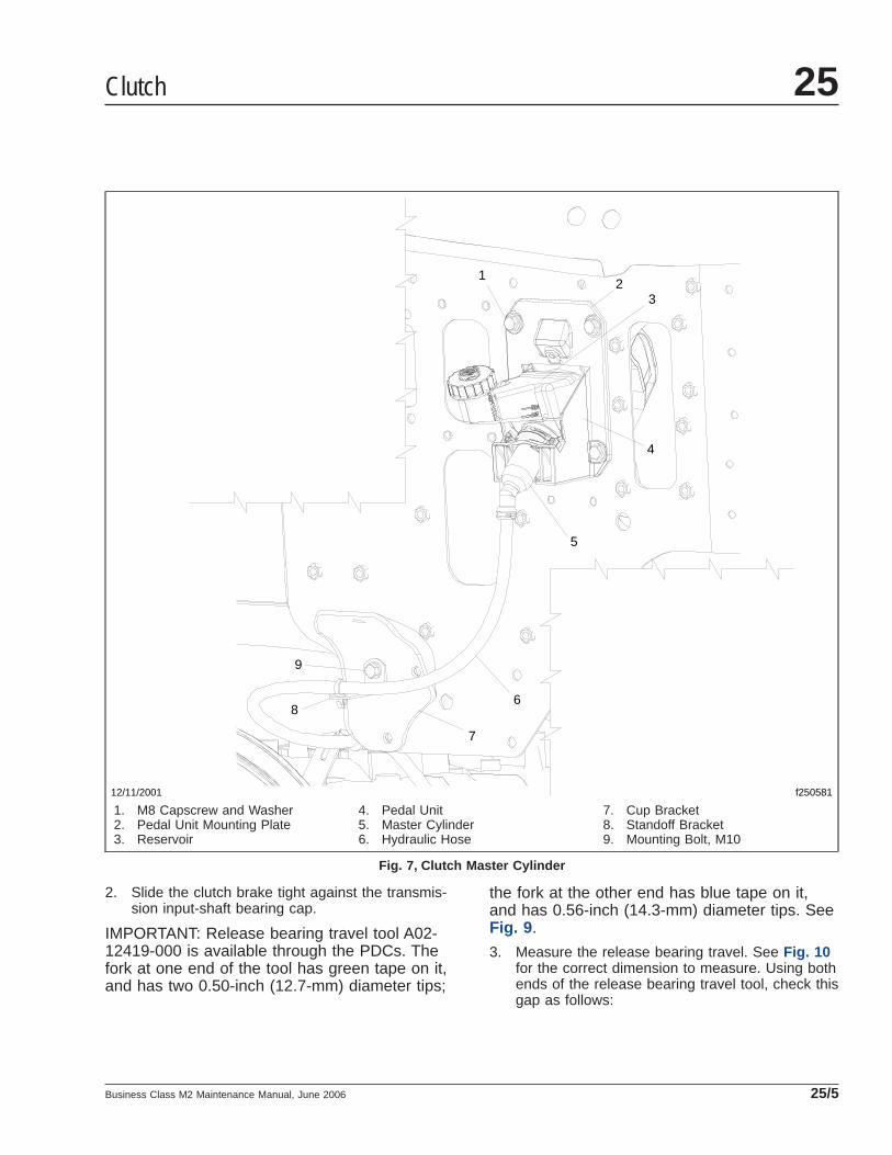
2. Slide the clutch brake tight against the transmis-sion input-shaft bearing cap.
IMPORTANT: Release bearing travel tool A02-12419-000 is available through the PDCs. Thefork at one end of the tool has green tape on it,and has two 0.50-inch (12.7-mm) diameter tips;
the fork at the other end has blue tape on it,and has 0.56-inch (14.3-mm) diameter tips. SeeFig. 9 .
3. Measure the release bearing travel. See Fig. 10for the correct dimension to measure. Using bothends of the release bearing travel tool, check thisgap as follows:
12
3
4
5
6
7
8
9
12/11/2001 f250581
1. M8 Capscrew and Washer2. Pedal Unit Mounting Plate3. Reservoir
4. Pedal Unit5. Master Cylinder6. Hydraulic Hose
7. Cup Bracket8. Standoff Bracket9. Mounting Bolt, M10
Fig. 7, Clutch Master Cylinder
Clutch 25
Business Class M2 Maintenance Manual, June 2006 25/5

Position the tool so that the legs of the fork atthe blue 0.56-inch (14.3-mm) end straddle thetransmission input shaft. If the tool fits loosely,the gap is too wide and adjustment is needed.Go to the next step.
If the blue 0.56-inch (14.3-mm) end can’t be in-serted in the gap, then try to insert the green0.50-inch (12.7-mm) end.
If the green end of the tool can’t be inserted inthe gap, adjustment is needed. Go to the nextstep.
If the green end of the tool fits — snugly orloosely — then no adjustment is needed. Nothingmore needs to be done. Install the clutch inspec-tion cover.
4. Turn the engine flywheel until the lockstrap isaligned with the clutch inspection-cover opening.
5. Release the clutch by depressing the pedal.Block the pedal in the released position, or havesomeone assist you by holding the pedal downduring the adjustment procedure.
NOTE: An open-end wrench is not recom-mended for the following step.
6. Adjust the clutch, using a 5/8-inch box-end orsocket wrench on the adjustment bolt. SeeFig. 11 .
6.1 Insert the 5/8-inch box-end or socketwrench through the inspection coveropening.
6.2 To begin the adjustment, release the ad-justment bolt by pressing down on thebolt head.
NOTE: On Easy-Pedal 2000 clutches, eachcomplete turn of the adjustment bolt repre-sents about 0.125 inch (3 mm) of releasebearing movement. On earlier Easy-Pedalmodels, each complete turn of the adjust-
06/22/2005 f2613551 2
3
1. Clutch Inspection Cover2. Hydraulic Slave Cylinder3. Transmission
Fig. 8, View from Underneath the Vehicle
f580133
A
A
B
B
03/26/96
A. Green End (0.50 inch or 12.7 mm)B. Blue End (0.56 inch or 14.3 mm)
Fig. 9, Release Bearing Travel Tool A02-12419-000
f250199a10/14/94
1 2
A
A. Clearance between release bearing housing andclutch brake must be 1/2 to 9/16 inch (12.7 to 14.3mm).
1. Release Bearing Housing2. Clutch Brake
Fig. 10, Release Bearing Travel Measurement
Clutch25
Business Class M2 Maintenance Manual, June 200625/6

ment bolt represents about 0.02 inch (0.5mm) of release bearing movement.
Normal wear increases the gap between therelease bearing and the transmission.
6.3 To decrease the gap: If clearance be-tween the release bearing housing andthe clutch brake is more than 9/16 inch(14.3 mm), turn the adjustment bolt clock-wise (the release bearing moves towardthe transmission).
To increase the gap: If clearance betweenthe release bearing housing and theclutch brake is less than 1/2 inch (12.7mm), turn the adjustment bolt counter-clockwise (the release bearing moves to-ward the engine).
6.4 When the adjustment is complete, makesure the adjustment bolt is locked (pulledup flush with the mounting bolts).
7. After adjusting, release the pedal and check theclearance between the release bearing housingand the clutch brake. When the adjustment iscorrect, the green end of the tool should go inand the blue should not (clearance of 1/2 to 9/16inch, or 12.7 to 14.3 mm).
8. Install the clutch inspection cover.
09/15/95 f250309
Fig. 11, Adjustment with Kwik-Adjust (shown with bellhousing removed)
Clutch 25
Business Class M2 Maintenance Manual, June 2006 25/7

Title of Maintenance Operation (MOP) MOP Number
Allison Transmission Fluid and Filter Changing . . . . . . . . . . . . . . . . . . . . . . . . . . . . . . . . . . . . . . . . . . . . 26–05
Allison and Eaton Fuller Transmission Breather Checking . . . . . . . . . . . . . . . . . . . . . . . . . . . . . . . . . . . . 26–03
Eaton Fuller Transmission Air Filter/Regulator Element Cleaning . . . . . . . . . . . . . . . . . . . . . . . . . . . . . . . 26–04
Eaton Fuller Transmission Fluid Changing and Magnetic Plug Cleaning . . . . . . . . . . . . . . . . . . . . . . . . . . 26–02
Manual Transmission Oil Level Checking . . . . . . . . . . . . . . . . . . . . . . . . . . . . . . . . . . . . . . . . . . . . . . . . 26–01
Mercedes-Benz Transmission Fluid Changing and Magnetic Plug Cleaning . . . . . . . . . . . . . . . . . . . . . . . 26–06
Mercedes-Benz Transmission Leak Checking . . . . . . . . . . . . . . . . . . . . . . . . . . . . . . . . . . . . . . . . . . . . . 26–07
Transmission 26Index, Alphabetical
Business Class M2 Maintenance Manual, March 2005

26–01 Manual Transmission OilLevel Checking
1. Park the vehicle on a level surface. Apply theparking brakes and chock the rear tires.
2. Check the oil level in the transmission. SeeFig. 1 .
2.1 Clean the area around the fill plug, thenremove the plug from the side of thecase.
2.2 Using your finger or a bent pipe cleaner,see if the oil is level with the lower edgeof the fill opening.
3. If needed, fill the transmission with oil until levelwith the lower edge of the fill opening. SeeTable 1 for approved lubricants.
Approved Manual Transmission Lubricants
Lubricant Type * Temperature:°F (°C)
SAEViscosity
Eaton Fuller Transmissions†
MobilTrans SHC 50 (RN2952 E-5) All 50
Synthetic lubricant approvedby Eaton All 50
Heavy-duty engine oilmeeting MIL-L-2104D orCaterpillar TO-4 Specification
Above 10 (–12) 40 or 50
Below 10 (–12) 30
API MT-1 gear oils meetingMIL-PRF-2105E specification
Above 10 (–12) 80 or 90
Below 10 (–12) 75
Mercedes-Benz Transmissions
Approved Manual Transmission Lubricants
Lubricant Type * Temperature:°F (°C)
SAEViscosity
MobilTrans SHC® DC All 50* Lubricants listed in order of preference. Do not mix types of oil.† Call 1-800-826-4357 for a complete list of Eaton approved lubricants.
Table 1, Approved Manual Transmission Lubricants
CAUTIONOperating a manual transmission with the fluidlevel higher or lower than recommended can re-sult in transmission damage. Do not overfill thetransmission; overfilling will force fluid out of thecase through the main shaft openings. Fluid over-flow may also drain onto the clutch or clutchbrake, causing additional problems.
IMPORTANT: Do not mix types of oil, becauseof possible incompatibility. Do not use oil addi-tives or friction modifiers. Do not use multi-viscosity oils or EP (Extreme Pressure) gearoils. If switching from a petroleum-based lubri-cant to a synthetic, all areas of each affectedcomponent must be thoroughly drained. Switch-ing to a synthetic lubricant, when a petroleum-based lubricant has been used for 50,000 miles(80 000 km) or longer may affect transmissionperformance. Monitor all seal areas for the first10,000 miles (16 000 km) after changing to asynthetic from a petroleum-based lubricant.
4. Clean the fill plug, then install it in the transmis-sion. Tighten the plug as follows:
• 25 to 35 lbf·ft (34 to 48 N·m) for EatonFuller transmissions with 3/4-inch pipethreads.
• 60 to 75 lbf·ft (81 to 102 N·m) for EatonFuller transmissions with 1-1/4-inch pipethreads.
• 42 lbf·ft (57 N·m) for all Mercedes-Benztransmissions.
f260006b10/05/94 A B
A. Full B. Low
Fig. 1, Transmission Oil Level Checking
Transmission 26
Business Class M2 Maintenance Manual, March 2005 26/1

26–02 Eaton FullerTransmission FluidChanging and MagneticPlug Cleaning
Eaton Fuller has a complete listing of approved lubri-cants for its transmissions on its internet website.Refer to the Eaton website for additional information,www.roadranger.com .
DrainingIMPORTANT: Manual transmissions filled withapproved synthetic lubricants require a lubricantdrain and fill, and a magnetic plug cleaningevery 500,000 miles (800 000 km), regardlessof the service or vocation of the vehicle. Manualtransmissions with petroleum-based lubricantsrequire a lubricant drain and fill, and a magneticplug cleaning at each Maintenance 2 (M2) inter-val. All transmissions, regardless of lubricationused, also require a check of the transmissionbreather at each Maintenance 1 (M1) interval.
1. Park the vehicle on a level surface. Apply theparking brakes and chock the rear tires.
2. Drain the fluid while the transmission is warm, asfollows.
2.1 Clean the area around the drain plug(s).Remove the drain plug(s) from the gearcase.
2.2 Clean the area around the fill plug. Re-move the fill plug from the gear case.
3. Clean the magnetic plug(s) before installing it.Use a piece of key stock, or any other conve-nient steel slug, to short the two magnetic polesand divert the magnetic field.
4. Install and tighten the drain plug(s) 50 lbf·ft (68N·m).
Filling
CAUTIONOperating a manual transmission with the fluidlevel higher or lower than recommended can re-sult in transmission damage. Do not overfill the
transmission; overfilling will force fluid out of thecase through the main shaft openings. Fluid over-flow may also drain onto the clutch or clutchbrake, causing additional problems.
IMPORTANT: Do not mix types of fluid, becauseof possible incompatibility. Do not use multi-viscosity fluids or EP (Extreme Pressure) gearfluids. Do not use fluid additives or friction modi-fiers. If switching from a petroleum-based lubri-cant to a synthetic lubricant, all areas of eachaffected component must be thoroughly drained.Switching to a synthetic lubricant, when apetroleum-based lubricant has been used for50,000 miles (80 000 km) or longer may affecttransmission performance. Monitor all sealareas for the first 10,000 miles (16 000 km)after changing to a synthetic lubricant from apetroleum-based lubricant.
NOTE: The correct fluid level is established bychecking at the fill plug opening.
1. Add fluid until it is level with the lower edge ofthe fill opening. See Fig. 1 . If the transmissionhas two fill openings, add fluid to the level ofboth fill openings. See Table 1 for approvedtransmission lubricants, and Table 2 for lubricantcapacities.
2. Clean the fill plug, then install it in the transmis-sion. Tighten the plug as follows:
• 25 to 35 lbf·ft (34 to 48 N·m) for EatonFuller transmissions with 3/4-inch pipethreads.
• 60 to 75 lbf·ft (81 to 102 N·m) for EatonFuller transmissions with 1-1/4-inch pipethreads.
26–03 Allison and Eaton FullerTransmission BreatherChecking
Transmission housing breathers (if equipped) mustremain clear. A plugged breather could result in pres-sure build-up, which could cause oil leakage.
If the breather is plugged, clean or replace it. SeeFig. 2 . Check more often if the vehicle is operatingunder very dusty conditions.
Transmission26
Business Class M2 Maintenance Manual, March 200526/2

Eaton Fuller Transmission Lubricant Capacities *
Transmission ModelLubricantCapacity:
qt (L)
5-Speed
FS–4205A/B, FS–5205A/B 6.25 (5.9)
FS–6305A/B 9.75 (9.2)
6-Speed
FS–5406A 9.75 (9.2)
FS–6406A, FSO–6406A 9.75 (9.2)
FO–6406A, FO-8406 10.5 (10.0)
FSO–8406A 9.75 (9.2)
7-Speed
T–14607A/B 18 (17.5)
TX–14607B 18 (17.5)
9-Speed
RT–6609A 6 (5.7)
RT–8709B 13.0 (12.3)
RT–8608L 13.5 (12.7)
10-Speed
FR–9210B 11.75 (11)
FRO–14210C, FRO–15210C 11.75 (11)
RT–8908LL 14 (13.2)
RTO–10910B AS2 13 (12.3)
RTO–11908LL 14 (13.2)
11-Speed
RTO–11909ALL 14 (13.2)
13-Speed
RTLO–14913A 14 (13.2)
18-Speed
RTLO–14918B 14 (13.2)
RTLO–16918B 14 (13.2)
* Quantities listed are approximate. Fill the transmission until the lubricantis level with the bottom of the fill hole, with the vehicle in normal operatingposition.
Table 2, Eaton Fuller Transmission LubricantCapacities
26–04 Eaton FullerTransmission Air Filter/Regulator ElementCleaning
NOTE: Eaton Fuller FS/FO and T/TX transmis-sions do not have an air filter/regulator elementthat can be serviced.
WARNINGExhaust the air supply before servicing the airfilter/regulator; otherwise, serious personal injuryand component damage could result.
1. Exhaust the air from the air reservoirs.
2. Clean the outside of the air filter/regulator withcleaning solvent, then let it air dry. See Fig. 3 .
3. Remove the end cap, large O-ring, and filter ele-ment from the filter housing. See Fig. 4 . Removethe small O-ring from the end cap.
NOTE: Do not remove, disassemble, or adjustthe air regulator. If the air regulator is not keep-ing the air pressure between 57 to 62 psi (396to 431 kPa), replace the air filter/regulator. Itcannot be repaired.
4. Clean the filter element.
f260007a05/27/93
NOTE: Location of the transmission breather will varydepending on transmission model.
Fig. 2, Transmission Breather (Eaton Fuller shown)
Transmission 26
Business Class M2 Maintenance Manual, March 2005 26/3
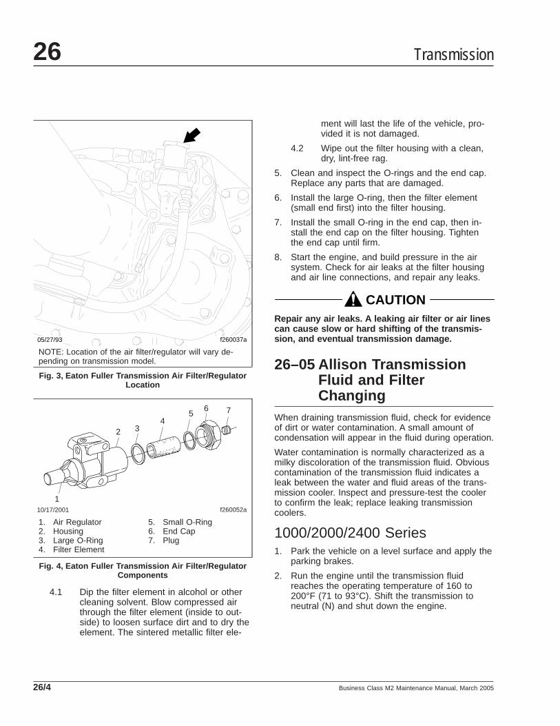
4.1 Dip the filter element in alcohol or othercleaning solvent. Blow compressed airthrough the filter element (inside to out-side) to loosen surface dirt and to dry theelement. The sintered metallic filter ele-
ment will last the life of the vehicle, pro-vided it is not damaged.
4.2 Wipe out the filter housing with a clean,dry, lint-free rag.
5. Clean and inspect the O-rings and the end cap.Replace any parts that are damaged.
6. Install the large O-ring, then the filter element(small end first) into the filter housing.
7. Install the small O-ring in the end cap, then in-stall the end cap on the filter housing. Tightenthe end cap until firm.
8. Start the engine, and build pressure in the airsystem. Check for air leaks at the filter housingand air line connections, and repair any leaks.
CAUTIONRepair any air leaks. A leaking air filter or air linescan cause slow or hard shifting of the transmis-sion, and eventual transmission damage.
26–05 Allison TransmissionFluid and FilterChanging
When draining transmission fluid, check for evidenceof dirt or water contamination. A small amount ofcondensation will appear in the fluid during operation.
Water contamination is normally characterized as amilky discoloration of the transmission fluid. Obviouscontamination of the transmission fluid indicates aleak between the water and fluid areas of the trans-mission cooler. Inspect and pressure-test the coolerto confirm the leak; replace leaking transmissioncoolers.
1000/2000/2400 Series1. Park the vehicle on a level surface and apply the
parking brakes.
2. Run the engine until the transmission fluidreaches the operating temperature of 160 to200°F (71 to 93°C). Shift the transmission toneutral (N) and shut down the engine.
f260037a05/27/93
NOTE: Location of the air filter/regulator will vary de-pending on transmission model.
Fig. 3, Eaton Fuller Transmission Air Filter/RegulatorLocation
1
2 34
56 7
f260052a10/17/2001
1. Air Regulator2. Housing3. Large O-Ring4. Filter Element
5. Small O-Ring6. End Cap7. Plug
Fig. 4, Eaton Fuller Transmission Air Filter/RegulatorComponents
Transmission26
Business Class M2 Maintenance Manual, March 200526/4

CAUTIONTo prevent dirt from entering the transmission,use only clean containers and fillers for the trans-mission fluid. Do not use fillers or containers thathave been used for water or antifreeze. Dirt, water,or antifreeze could damage the transmission.
3. Clean the area around the drain plug. Place adrain pan under the transmission and remove thedrain plug. Examine the fluid while it drains. Ifonly the filter is being changed, do not drain thefluid.
NOTE: A lot of fluid will drain when the filter isremoved.
4. Using a standard strap-type filter wrench, removethe filter by turning it counterclockwise.
5. Remove the magnet from the filter attachmenttube or from the top of the filter element.
6. Clean any metal debris from the magnet. Then,install the magnet on the filter attachment tube.
7. Using transmission fluid, lubricate the gasket onthe filter.
8. Using your hand, install the filter by turning itclockwise until the filter gasket contacts the con-verter housing or cooler manifold. Then, turn thefilter one more complete turn.
9. Install the drain plug and sealing washer. Tightenthe plug 22 to 30 lbf·ft (30 to 40 N·m).
10. Clean the area around the fill tube and removethe dipstick. Using a clean funnel in the fill tube,add transmission fluid. See Table 3 for approvedtransmission lubricants, and Table 4 for lubricantcapacities.
11. Check and adjust the fluid level using the proce-dure under "Checking the Fluid Level."
MD and HD Series
CAUTIONTo prevent dirt from entering the transmission,use only clean containers and fillers for the trans-mission fluid. Do not use fillers or containers thathave been used for water or antifreeze. Dirt, water,or antifreeze could damage the transmission.
Approved Allison Transmission Lubricants
Lubricant Type * Temperature: °F (°C)
All Allison Transmissions
Castrol TranSynd™ (synthetic) Above –22 (–30)
Dexron® III Above –13 (–25)
* Lubricants listed in order of preference. Do not mix types of oil.
Table 3, Approved Allison Transmission Lubricants
Allison Transmission Lubricant Capacities
Transmission Model Fill Capacity: *qt (L)
On-Highway Transmissions
1000/2000/2400 Series (standard sump) 15 (14)
1000/2000/2400 Series (shallow sump) 13 (12)
HD/MD Series
HD4060/4560 (standard sump) 36 (34)†
HD4060/4560 (shallow sump) 26 (25)†
MD3060/3066/3560 (standard sump) 19 (18)
MD3060/3066/3560 (shallow sump) 10.5 (10)
* Quantities listed are approximate. Add the recommended amount of fluidas listed under fill capacity, then perform a "hot check" and add fluid asneeded. Do not overfill.† Add 3 quarts (3 liters) if equipped with a PTO.
Table 4, Allison Transmission Lubricant Capacities
1. Park the vehicle on a level surface and apply theparking brakes.
2. Operate the vehicle until the transmissionreaches normal operating temperature: 160 to200°F (71 to 93°C).
3. Clean the area around the drain plug and thetransmission fluid pan. Place a drain pan underthe transmission and remove the drain plug. Ex-amine the fluid as it drains. If only the filter isbeing changed, do not drain the fluid.
4. Remove the 12 mounting bolts (six each) fromthe two filter covers.
NOTE: A lot of fluid will drain when the filtercovers are removed.
5. Remove the filter covers, O-rings, and twosquare-cut seals from the transmission. SeeFig. 5 .
Transmission 26
Business Class M2 Maintenance Manual, March 2005 26/5
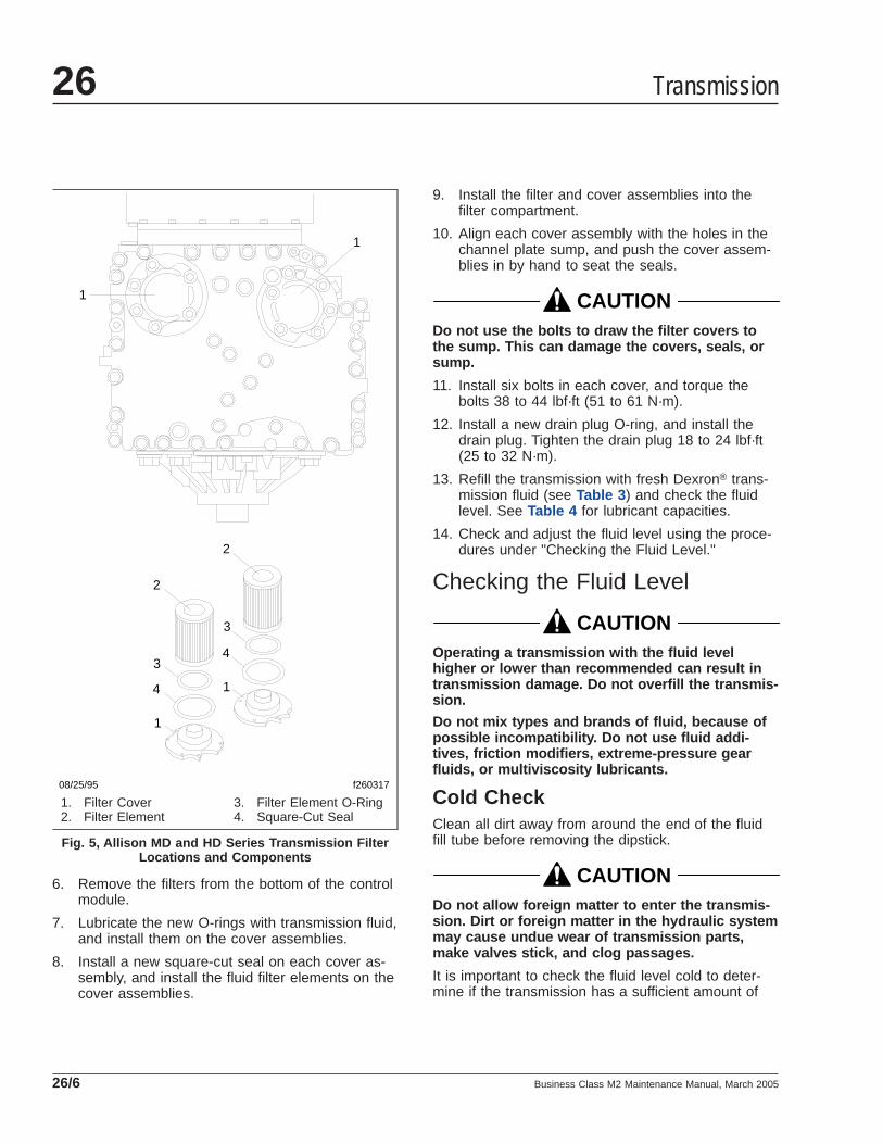
6. Remove the filters from the bottom of the controlmodule.
7. Lubricate the new O-rings with transmission fluid,and install them on the cover assemblies.
8. Install a new square-cut seal on each cover as-sembly, and install the fluid filter elements on thecover assemblies.
9. Install the filter and cover assemblies into thefilter compartment.
10. Align each cover assembly with the holes in thechannel plate sump, and push the cover assem-blies in by hand to seat the seals.
CAUTIONDo not use the bolts to draw the filter covers tothe sump. This can damage the covers, seals, orsump.
11. Install six bolts in each cover, and torque thebolts 38 to 44 lbf·ft (51 to 61 N·m).
12. Install a new drain plug O-ring, and install thedrain plug. Tighten the drain plug 18 to 24 lbf·ft(25 to 32 N·m).
13. Refill the transmission with fresh Dexron® trans-mission fluid (see Table 3 ) and check the fluidlevel. See Table 4 for lubricant capacities.
14. Check and adjust the fluid level using the proce-dures under "Checking the Fluid Level."
Checking the Fluid Level
CAUTIONOperating a transmission with the fluid levelhigher or lower than recommended can result intransmission damage. Do not overfill the transmis-sion.
Do not mix types and brands of fluid, because ofpossible incompatibility. Do not use fluid addi-tives, friction modifiers, extreme-pressure gearfluids, or multiviscosity lubricants.
Cold CheckClean all dirt away from around the end of the fluidfill tube before removing the dipstick.
CAUTIONDo not allow foreign matter to enter the transmis-sion. Dirt or foreign matter in the hydraulic systemmay cause undue wear of transmission parts,make valves stick, and clog passages.
It is important to check the fluid level cold to deter-mine if the transmission has a sufficient amount of
1
1
1
1
2
2
3
3
4
4
f26031708/25/95
1. Filter Cover2. Filter Element
3. Filter Element O-Ring4. Square-Cut Seal
Fig. 5, Allison MD and HD Series Transmission FilterLocations and Components
Transmission26
Business Class M2 Maintenance Manual, March 200526/6

fluid to be safely operated until a hot check can beperformed.
1. Park the vehicle on a flat, level surface.
2. Apply the parking brakes and chock the reartires.
3. Run the engine for at least one minute.
4. Shift from DRIVE to NEUTRAL, and then shift toREVERSE to fill the hydraulic system.
5. Shift to NEUTRAL and allow the engine to idle at500 to 800 rpm.
6. With the engine running at idle, remove the dip-stick from the tube and wipe it clean.
7. Insert the dipstick into the tube, then remove thedipstick.
8. Check the fluid level reading and repeat thecheck procedure to verify the reading.
If the fluid level is within the COLD RUN band,the transmission may be operated until the fluidis hot enough to perform a HOT RUN check.
If the fluid level is not within the COLD RUNband, add or drain fluid as needed to adjust thefluid level to the middle of the COLD RUN band.See Fig. 6 .
CAUTIONDo not fill above the COLD RUN band if the trans-mission fluid is below normal operating tempera-ture. As fluid temperature increases, so does thefluid level. Filling above the COLD RUN bandwhen the transmission is below normal operatingtemperature may result in an overfilled transmis-sion, which causes fluid foaming and aeration.
Fluid foaming and aeration cause transmissionoverheating and erratic shifting.
NOTE: Perform a hot check at the first opportu-nity after the normal operating temperature, 160to 200°F (71 to 93°C) has been reached.
Hot Check1. Park the vehicle on a flat, level surface. Apply
the parking brakes and chock the rear tires.
2. Shift the transmission to NEUTRAL.
3. Operate the engine at idle (500 to 800 rpm) untilnormal operating temperature is reached. Checkthat the sump temperature is 160 to 200°F (71 to93°C). Check that the converter-out temperatureis 180 to 220°F (82 to 104°C).
4. With the engine idling, remove the dipstick fromthe tube and wipe it clean.
5. Insert the dipstick into the tube, then remove it.
6. Check the fluid level reading and repeat thecheck procedure to verify the reading. Safe oper-ating level is within the HOT RUN band on thedipstick. The HOT RUN band is between theHOT FULL and HOT ADD marks.
If the fluid level is not within the HOT RUN band,add or drain fluid as needed to bring the fluidlevel within the HOT RUN band. See Fig. 6 .
26–06 Mercedes-BenzTransmission FluidChanging and MagneticPlug Cleaning
Draining1. Park the vehicle on a level surface. Apply the
parking brakes and chock the rear tires.
NOTE: Drain the transmission fluid while thetransmission is warm.
2. Drain the transmission fluid, as follows. SeeFig. 7 .
2.1 Remove the magnetic drain plug from thebottom of the gear case.
2.2 Discard the aluminum gasket.
12/01/97
A
B
f270002a
A. Cold Run Band B. Hot Run Band
Fig. 6, Dipstick Markings
Transmission 26
Business Class M2 Maintenance Manual, March 2005 26/7
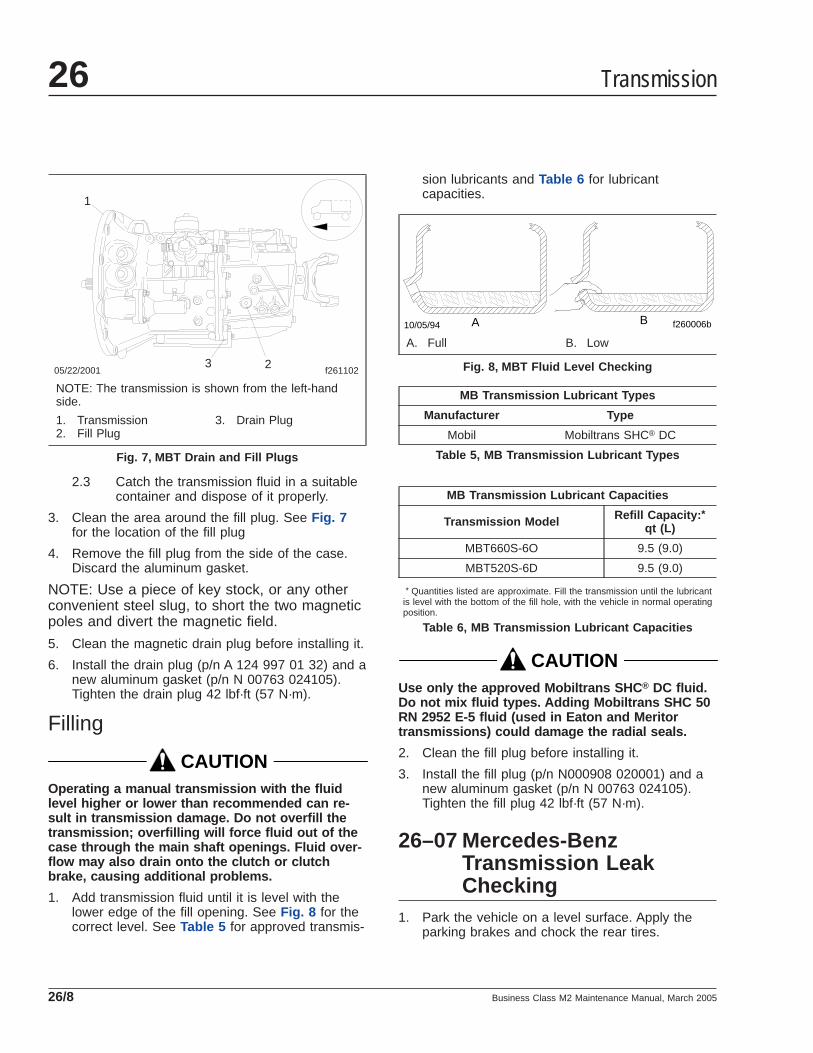
2.3 Catch the transmission fluid in a suitablecontainer and dispose of it properly.
3. Clean the area around the fill plug. See Fig. 7for the location of the fill plug
4. Remove the fill plug from the side of the case.Discard the aluminum gasket.
NOTE: Use a piece of key stock, or any otherconvenient steel slug, to short the two magneticpoles and divert the magnetic field.
5. Clean the magnetic drain plug before installing it.
6. Install the drain plug (p/n A 124 997 01 32) and anew aluminum gasket (p/n N 00763 024105).Tighten the drain plug 42 lbf·ft (57 N·m).
Filling
CAUTIONOperating a manual transmission with the fluidlevel higher or lower than recommended can re-sult in transmission damage. Do not overfill thetransmission; overfilling will force fluid out of thecase through the main shaft openings. Fluid over-flow may also drain onto the clutch or clutchbrake, causing additional problems.
1. Add transmission fluid until it is level with thelower edge of the fill opening. See Fig. 8 for thecorrect level. See Table 5 for approved transmis-
sion lubricants and Table 6 for lubricantcapacities.
MB Transmission Lubricant Types
Manufacturer Type
Mobil Mobiltrans SHC® DC
Table 5, MB Transmission Lubricant Types
MB Transmission Lubricant Capacities
Transmission Model Refill Capacity: *qt (L)
MBT660S-6O 9.5 (9.0)
MBT520S-6D 9.5 (9.0)
* Quantities listed are approximate. Fill the transmission until the lubricantis level with the bottom of the fill hole, with the vehicle in normal operatingposition.
Table 6, MB Transmission Lubricant Capacities
CAUTIONUse only the approved Mobiltrans SHC ® DC fluid.Do not mix fluid types. Adding Mobiltrans SHC 50RN 2952 E-5 fluid (used in Eaton and Meritortransmissions) could damage the radial seals.
2. Clean the fill plug before installing it.
3. Install the fill plug (p/n N000908 020001) and anew aluminum gasket (p/n N 00763 024105).Tighten the fill plug 42 lbf·ft (57 N·m).
26–07 Mercedes-BenzTransmission LeakChecking
1. Park the vehicle on a level surface. Apply theparking brakes and chock the rear tires.
05/22/2001 f261102
1
23
NOTE: The transmission is shown from the left-handside.
1. Transmission2. Fill Plug
3. Drain Plug
Fig. 7, MBT Drain and Fill Plugs
f260006b10/05/94 A B
A. Full B. Low
Fig. 8, MBT Fluid Level Checking
Transmission26
Business Class M2 Maintenance Manual, March 200526/8

2. Check for signs of leakage at the breather. SeeFig. 9 .
2.1 If leakage is found, check the breather fora missing cap. Replace the cap if neces-sary.
2.2 Check the fluid level at the fill plug. If thelevel is too high, correct the fluid level.
3. Check for signs of leakage at the cap seal on theshift lever. If the cap seal is damaged, replace it.
4. Check for signs of leakage at the radial seal onthe output shaft. If leakage is found, remove theoutput yoke (end yoke) and replace the seal. Forprocedures, see Section 26.02, Subject 120 ofthe Business Class® M2 Workshop Manual.
NOTE: There are two cover plates on the coun-tershaft, one at the front and one at the rear.
5. Check for signs of leakage at the rear coverplate on the countershaft (next to the outputyoke). If leakage is found, check the torque onthe cover-plate bolts and check the flat seal fordamage.
5.1 If the flat seal is damaged, replace it.
5.2 If the cover-plate bolts are too loose,tighten them 18 lbf·ft (25 N·m). If thecover-plate bolts are too tight, replace theflat seal and tighten to 18 lbf·ft (25 N·m).
6. Check for signs of leakage at the transmissionfluid fill plug. If leakage is found, check thetorque on the plug and check the aluminum gas-ket for damage.
6.1 If the gasket is damaged, replace it.
6.2 If the fill plug is too loose, tighten it 42lbf·ft (57 N·m). If the fill plug is too tight,loosen it, then tighten it to 42 lbf·ft (57N·m).
7. Check for signs of leakage at the transmissionfluid drain plug. If leakage is found, check thetorque on the plug and check the aluminum gas-ket for damage.
7.1 If the gasket is damaged, replace it.
7.2 If the drain plug is too loose, tighten it 42lbf·ft (57 N·m). If the plug is too tight,loosen it, then tighten it to 42 lbf·ft (57N·m).
8. Check for fluid dripping at the gear case seals. Ifsubstantial leakage is found at either location,replace the transmission.
NOTE: Weeping or sweating seals are notcause for transmission replacement.
WARNINGClutch hydraulic fluid (DOT 4 brake fluid) is haz-ardous. It may be a skin irritant and can causeblindness if it gets in your eyes. Always wearsafety glasses when handling clutch hydraulicfluid or bleeding hydraulic lines. If you get clutchhydraulic fluid on your skin, wash it off as soonas possible.
9. Check for signs of leakage at the clutch slavecylinder.
CAUTIONDo not spill clutch hydraulic fluid (DOT 4 brakefluid) on the cab paint. Clean it off immediately ifany is spilled. DOT 4 brake fluid can damagepaint.
05/22/2001 f261101
12
3
4
5678
9
NOTE: The transmission is shown from the left-handside.
1. Shift Lever Cap Seal2. Breather3. Output Shaft Radial Seal4. Countershaft Cover Plate5. Transmission Fluid Fill Plug6. Transmission Fluid Drain Plug7. Gear Case Seals8. Clutch Slave Cylinder9. Input Shaft Radial Seal
Fig. 9, MBT Leak Check
Transmission 26
Business Class M2 Maintenance Manual, March 2005 26/9
9.1 If leakage is found on the slave cylinderbody, check the fittings and hose for dam-age.
9.2 If leakage is found on the piston seals,replace the slave cylinder and bleed theclutch hydraulic system. For detailed in-structions, see Group 25 of the BusinessClass® M2 Workshop Manual.
9.3 If the slave cylinder fittings and/or thehose are damaged, replace them.
9.4 Check the torque on the slave cylindermounting capscrews. Tighten them 13lbf·ft (18 N·m).
9.5 If any leakage of clutch hydraulic fluid isfound, check the fluid level in the reser-voir, and add fluid if needed. For detailedprocedures, see Group 25 of thismanual.
NOTE: There are two cover plates on the coun-tershaft, one at the front and one at the rear.
10. Check for signs of leakage at the clutch bellhousing. If leakage is found, check the radialseal on the input shaft, the front cover plate onthe countershaft (inside the clutch bell housing),and the rear radial seal on the crankshaft.
10.1 If the radial seal on the input shaft isleaking, replace the radial seal. For pro-cedures, see Section 26.02, Subject 120of the Business Class® M2 WorkshopManual.
10.2 If the cover plate on the countershaft isleaking, replace the cover plate. Applyliquid gasket (Loctite 518) to the newcover plate when installing it.
10.3 If the rear radial seal on the enginecrankshaft is leaking, replace the rear ra-dial seal. For procedures, see the enginemanufacturer’s manual.
11. Remove the chocks from the tires.
Transmission26
Business Class M2 Maintenance Manual, March 200526/10
Title of Maintenance Operation (MOP) MOP Number
Fifth Wheel Inspecting . . . . . . . . . . . . . . . . . . . . . . . . . . . . . . . . . . . . . . . . . . . . . . . . . . . . . . . . . . . . . . 31–02
Fifth Wheel Lubricating. . . . . . . . . . . . . . . . . . . . . . . . . . . . . . . . . . . . . . . . . . . . . . . . . . . . . . . . . . . . . . 31–03
Frame Fastener Torque Checking. . . . . . . . . . . . . . . . . . . . . . . . . . . . . . . . . . . . . . . . . . . . . . . . . . . . . . 31–01
Trailer Electrical Connector Lubricating . . . . . . . . . . . . . . . . . . . . . . . . . . . . . . . . . . . . . . . . . . . . . . . . . . 31–04
Frame and Frame Components 31Index, Alphabetical
Business Class M2 Maintenance Manual, May 2011

31–01 Frame Fastener TorqueChecking
Frame brackets and components secured with Huck-bolt® fasteners do not require a torque check, how-ever, they should be inspected for damage. Framebrackets and components secured with conventionalbolts and nuts are to be checked at initial mainte-nance (IM).
Check the torque of frame fasteners to offset the ef-fects of bedding in or seating. When possible, alwayscheck the torque of the nut, not the bolt head. Thiswill give a true torque reading by eliminating boltbody friction.
When checking the torque of frame fasteners, in-spect the frame for cracks and other damage. Set aclick-type torque wrench to the maximum torque ofthe fastener you are checking. Apply pressure untilthe torque wrench clicks. Do not loosen the bolt tocheck the torque. See the applicable torque table inGroup 00 for torque specifications.
NOTICEMake sure frame fasteners are properly tightened.Continued vehicle operation with loose fastenerscould result in bracket or frame damage.
NOTE: Engine supports on vehicles built fromJanuary 2007 do not require checking.
Inspect the fasteners at the following locations:
• axle stops
• equalizer brackets
• engine trunnion supports
• exhaust brackets
• fifth wheel legs
• fifth wheel mountings
• frame crossmembers and gussets
• front frame brackets
• front suspension spring brackets
• fuel tank brackets
• radius rods
• rear suspension spring brackets
• rear engine supports
• shock absorbers
• all other frame fasteners
Any component that shows signs of cracking or dam-age must be repaired or replaced. See the applicablegroup in the Business Class® M2 Workshop Manualfor repair or replacement information.
31–02 Fifth Wheel Inspecting
WARNINGAll fifth wheel maintenance, adjustment, and re-building must be done only by a qualified me-chanic. Improper or incomplete procedures couldresult in a possible disengagement of the trailerfrom the tractor, which could result in personalinjury or property damage.
Parts are under spring compression. Wear safetygoggles while servicing the fifth wheel. Failure todo so can result in personal injury, due to partsejecting with force.
Fontaine1. Disconnect the tractor from the trailer. For in-
structions, see the Business Class M2 Driver’sManual.
2. Thoroughly steam clean the fifth wheel.
3. Check for cracks in the fifth wheel assembly,mounting brackets, and mounting parts.
4. Ensure that both bracket pins are in place andsecured by retainer pins and cotter pins. SeeFig. 1 .
5. For fifth wheels equipped with bracket liners,rock the fifth wheel. If it does not rock freely, re-move the top plate and inspect the bracket lin-ers. Replace liners that are broken or less than0.125 inch (3 mm) thick at the top of the liners.For the liner replacement procedure, see theFontaine website, www.fifthwheel.com .
6. Check the jaw and stationary jaw for mushroom-ing, and check that the serrations at the jaw andwedge are in good condition.
7. Test the secondary safety lock latch for ease ofoperation.
Frame and Frame Components 31
Business Class M2 Maintenance Manual, May 2011 31/1
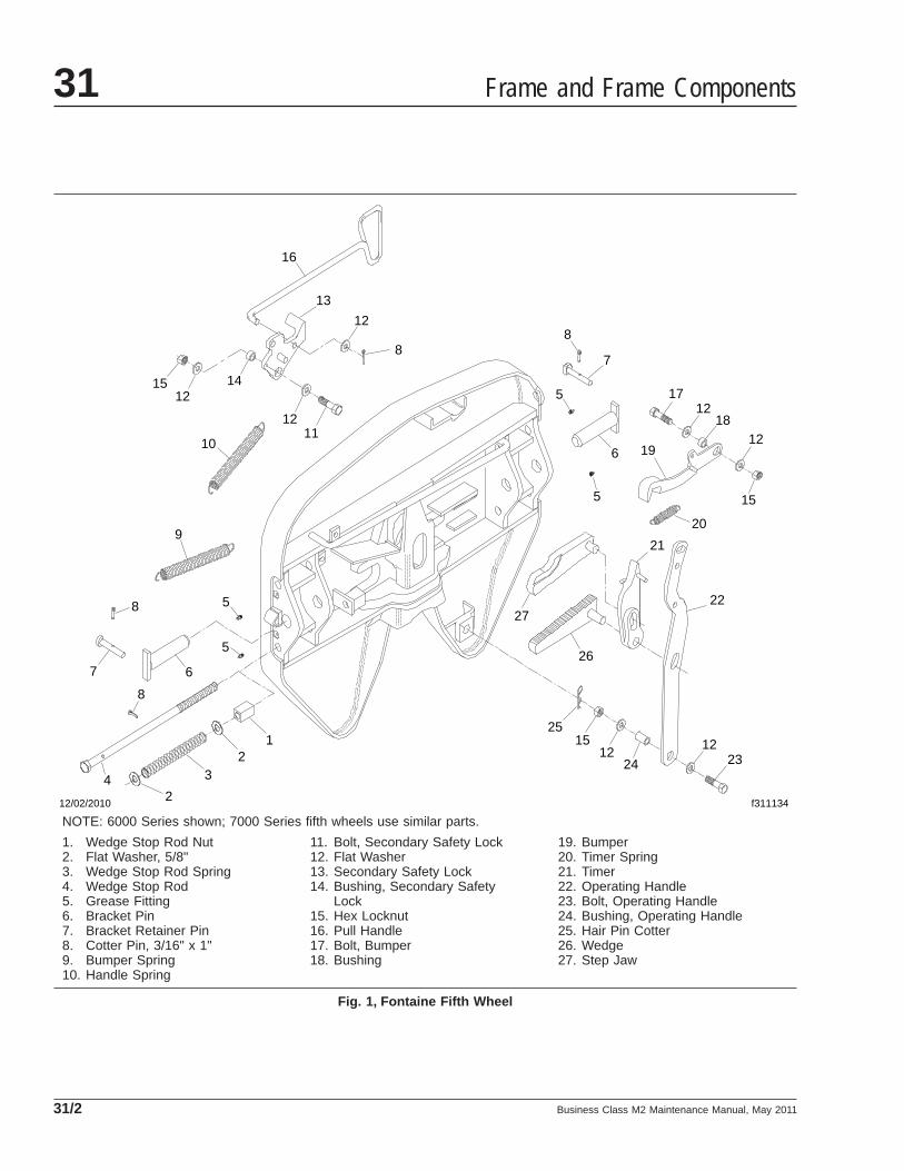
12/02/2010 f311134
12
2
34
5
5
67
8
8
9
1011
12
12
12
13
1415
16
87
6
5
5
8
1712
1218
15
19
20
21
22
2312
1224
1525
26
27
NOTE: 6000 Series shown; 7000 Series fifth wheels use similar parts.
1. Wedge Stop Rod Nut2. Flat Washer, 5/8"3. Wedge Stop Rod Spring4. Wedge Stop Rod5. Grease Fitting6. Bracket Pin7. Bracket Retainer Pin8. Cotter Pin, 3/16" x 1"9. Bumper Spring10. Handle Spring
11. Bolt, Secondary Safety Lock12. Flat Washer13. Secondary Safety Lock14. Bushing, Secondary Safety
Lock15. Hex Locknut16. Pull Handle17. Bolt, Bumper18. Bushing
19. Bumper20. Timer Spring21. Timer22. Operating Handle23. Bolt, Operating Handle24. Bushing, Operating Handle25. Hair Pin Cotter26. Wedge27. Step Jaw
Fig. 1, Fontaine Fifth Wheel
Frame and Frame Components31
Business Class M2 Maintenance Manual, May 201131/2

8. Check for loose nuts or bolts on the fifth wheeland the mounting. Set a torque wrench to themaximum torque value for the bolt beingchecked, and confirm that the torque is to speci-fication. Do not loosen the bolt to check thetorque. See Group 00 for bolt torque specifica-tions.
9. Check all springs to see if they are securely fas-tened, and are not deformed.
WARNINGDo not disassemble the fifth wheel to inspect thesprings. The springs are under extreme pressure,and could cause serious injury.
10. Check wedge adjustment.
10.1 Open the kingpin lock, and vertically in-sert a 2-inch (50-mm) diameter shaft.
10.2 Release the lock by tripping the releaselatch at the bottom of the throat.
10.3 Adjust the wedge stop at the end of thewedge to approximately 1/4-inch (6-mm)clearance by turning the wedge stop rodlocated on the right side of the top plate.
11. Replace cracked, worn, or damaged parts withnew parts. Replace all loose mounting bolts with5/8–11 SAE grade 8 bolts, grade C locknuts, andhardened washers. Do not re-use bolts, nuts,and washers on fifth wheel mountings.
12. After inspecting the fifth wheel, lubricate all mov-ing parts with a chassis or multipurpose grease.Apply a generous coating of grease to the topplate to fill the grooves, or depressions, on thetop plate. See MOP 31–03 for lubrication instruc-tions.
ConMet Simplex®
1. Disconnect the tractor from the trailer. For in-structions, see Chapter 10 of the BusinessClass® M2 Driver’s Manual
2. Thoroughly steam-clean the fifth wheel.
3. Check the fifth wheel plate for cracks. Check forsharp edges on top; the chamfer should be 1/8to 1/4 inch (3 to 6 mm).
4. When the wheel is locked, the safety latch mustswing free and fall freely into position. See Fig.2.
5. The lever bar and operating handle must be inproper alignment. See Fig. 3 . Replace any bentor misaligned lever bar or operating rod.
6. Check all clinch pins for cracking or damage.Replace any clinch pin that shows signs of dam-age.
7. Measure the top plate lift. See Fig. 4 .
7.1 Level the fifth wheel plate to a horizontalposition.
f310353b
12
3
4
10/26/2010
1. Lubricant Grooves2. Safety Latch
3. Lock Control Handle4. Mount
Fig. 2, Simplex Series Fifth Wheel
04/11/2011 f310470
1
2
1. Operating Handle 2. Lever Bar
Fig. 3, Lever Bar and Operating Handle Alignment
Frame and Frame Components 31
Business Class M2 Maintenance Manual, May 2011 31/3

7.2 Measure the height from a stationarymounting point, such as the frame rail tothe top of the fifth wheel plate.
7.3 Pry up on the fifth wheel plate below thepin boss, and measure the vertical move-ment.
NOTE: The bracket connection provides a9/32-inch (7-mm) vertical clearance to pro-vide cushioning and to avoid downward pin-loading while retaining minimum plate lift.
7.4 If the plate lift exceeds 5/16 inch (8 mm)as a result of wear or rubber deteriora-tion, install new, standard or oversizedbracket-shoe rubber pads; see the Sim-plex Fifth Wheel Operating and Mainte-nance Manual for replacement instruc-tions.
NOTE: Do not measure plate lift immediatelyafter a trailer has been uncoupled from the fifthwheel. The rubber may have taken a temporaryset, which will normally recover after being un-coupled for a short period of time.
8. Check the clearance between the kingpin andthe jaw of the fifth wheel. If the clearance isgreater than 1/8 inch (3 mm), dial out the slackusing the eccentric jaw pin. For detailed instruc-
tions, see the Simplex Fifth Wheel Operating andMaintenance Manual.
9. Check all mounting bolts for signs of fatigue, andtighten them to the proper torque. For torquespecifications, see Group 00 . Inspect all angles,plates, and brackets for cracks or other damage.
10. Replace cracked, worn, or damaged parts withnew parts. Replace all loose mounting bolts with5/8–11 SAE grade 8 bolts, grade C locknuts, andhardened washers. Do not re-use bolts, nuts,and washers on fifth wheel mountings.
11. After inspecting the fifth wheel, lubricate all mov-ing parts with a chassis or multipurpose grease.See Maintenance Operation 31–03 for lubrica-tion instructions.
Holland FWS11. Disconnect the tractor from the trailer. For in-
structions, see the Business Class M2 Driver’sManual.
2. Thoroughly steam clean the fifth wheel.
3. Check the fifth wheel plate for cracks. Check forsharp edges on top; the chamfer should be 1/8to 1/4 inch (3 to 6 mm).
4. When the wheel is locked, the safety latch mustswing free and fall freely into position. See Fig.5.
f31047504/11/2011
1
23
A
4
5
A. Extended Top Plate Lift Height1. Fifth Wheel Top Plate2. Fifth Wheel Frame Mount3. Frame Rail4. Lifting Point5. Static Top Plate Height
Fig. 4, Measuring Fifth Wheel Top Plate Lift
f31105210/29/2007
1
2
3
4
1. Lubricant Grooves2. Safety Latch
3. Release Handle4. Mount
Fig. 5, Holland FWS1 Fifth Wheel
Frame and Frame Components31
Business Class M2 Maintenance Manual, May 201131/4

5. The lever bar and release handle must be inproper alignment. See Fig. 6 . Compare the leverbar and release handle alignment to a new, or aproperly operating lever bar and release handle.Replace any bent or misaligned lever bar or re-lease handle.
6. Check all cotter pins for cracking or damage. Re-place any cotter pin that shows any signs ofdamage.
7. Check all mounting bolts for signs of fatigue, andtighten them to the proper torque. For torquespecifications, see Group 00 . Inspect all angles,plates, and brackets for cracks or other damage.
8. Replace cracked, worn, or damaged parts withnew parts. Replace all loose mounting bolts with5/8–11 SAE grade 8 bolts, grade C locknuts, andhardened washers. Do not re-use bolts, nuts,and washers on fifth wheel mountings.
9. After inspecting the fifth wheel, lubricate all mov-ing parts with a chassis or multipurpose grease.See MOP 31–03 for lubrication instructions.
Holland FW351. Disconnect the tractor from the trailer. For in-
structions, see the Business Class M2 Driver’sManual.
2. Thoroughly steam clean all fifth wheel compo-nents before inspection.
3. Check for cracks in the fifth wheel assembly,mounting brackets, and mounting parts.
4. Check the fastener torques on the fifth wheelassembly and fifth wheel mounting. Tighten boltsand nuts as needed. Replace missing or dam-aged bolts.
5. Inspect the fifth wheel for bent, worn, damaged,and missing parts; replace them as needed withgenuine Holland parts.
6. Using a Holland Kingpin Lock Tester (Hollandtool number TF-TLN-5001, available through thePDCs as HLD TFTLN5001), check the operationof the locking mechanism by opening and closingthe locks. See Fig. 7 .
7. After inspecting the fifth wheel, lubricate all mov-ing parts with a chassis or multipurpose grease.See MOP 31–03 for lubrication instructions.
Jost1. Disconnect the tractor from the trailer. For in-
structions, see the Business Class M2 Driver’sManual.
2. Thoroughly steam clean the fifth wheel.
3. Check the mounting for missing or damaged fas-teners, and broken components. Replace or re-pair as needed.
01/13/2011 f310470
1
2
1. Release Handle 2. Lever Bar
Fig. 6, Lever Bar and Release Handle Alignment
04/11/2011 f310887
A
B
A. The nut and washer should be snug against the fifthwheel.
B. The locks should be completely closed around thekingpin.
Fig. 7, Holland Fifth Wheel Properly Closed
Frame and Frame Components 31
Business Class M2 Maintenance Manual, May 2011 31/5
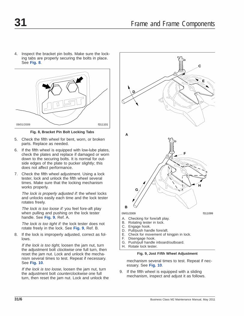
4. Inspect the bracket pin bolts. Make sure the lock-ing tabs are properly securing the bolts in place.See Fig. 8 .
5. Check the fifth wheel for bent, worn, or brokenparts. Replace as needed.
6. If the fifth wheel is equipped with low-lube plates,check the plates and replace if damaged or worndown to the securing bolts. It is normal for out-side edges of the plate to pucker slightly; thisdoes not affect performance.
7. Check the fifth wheel adjustment. Using a locktester, lock and unlock the fifth wheel severaltimes. Make sure that the locking mechanismworks properly.
The lock is properly adjusted if: the wheel locksand unlocks easily each time and the lock testerrotates freely.
The lock is too loose if: you feel fore-aft playwhen pulling and pushing on the lock testerhandle. See Fig. 9 , Ref. A.
The lock is too tight if: the lock tester does notrotate freely in the lock. See Fig. 9 , Ref. B.
8. If the lock is improperly adjusted, correct as fol-lows.
If the lock is too tight, loosen the jam nut, turnthe adjustment bolt clockwise one full turn, thenreset the jam nut. Lock and unlock the mecha-nism several times to test. Repeat if necessary.See Fig. 10 .
If the lock is too loose, loosen the jam nut, turnthe adjustment bolt counterclockwise one fullturn, then reset the jam nut. Lock and unlock the
mechanism several times to test. Repeat if nec-essary. See Fig. 10 .
9. If the fifth wheel is equipped with a slidingmechanism, inspect and adjust it as follows.
09/01/2009 f311101
Fig. 8, Bracket Pin Bolt Locking Tabs
09/01/2009 f311099
A
B
C
D
E
F
GH
A. Checking for fore/aft play.B. Rotating tester in lock.C. Engage hook.D. Pull/push handle fore/aft.E. Check for movement of kingpin in lock.F. Disengage hook.G. Push/pull handle inboard/outboard.H. Rotate lock tester.
Fig. 9, Jost Fifth Wheel Adjustment
Frame and Frame Components31
Business Class M2 Maintenance Manual, May 201131/6

9.1 Check the bracket for any cracks or miss-ing and damaged parts.
9.2 Inspect the locking plungers for full en-gagement.
9.3 Check the locking mechanism for properoperation.
If the plungers will not release, check theair cylinder or plunger adjustment.
If the plungers are loose, check theplunger adjustment and the plungersprings for proper compression. Replaceif needed.
9.4 The outboard slider assembly requires noadjustment. If the plungers are loose, in-spect and replace locking mechanismparts as needed.
9.5 The inboard slider is adjustable for framewidth and plunger engagement. For ad-
justment, refer to the fifth wheel installa-tion instructions.
10. Replace cracked, worn, or damaged parts withnew parts. Replace all loose mounting bolts with5/8–11 SAE grade 8 bolts, grade C locknuts, andhardened washers. Do not re-use bolts, nuts,and washers on fifth wheel mountings.
11. After inspecting the fifth wheel, lubricate all mov-ing parts with a chassis or multipurpose grease.Apply a generous coating of grease to the topplate to fill the grooves, or depressions, on thetop plate. See MOP 31–03 for lubrication instruc-tions.
31–03 Fifth Wheel Lubricating
Fontaine1. Tilt the top plate forward (the front of the fifth
wheel is down) and apply grease to each bearingarea through the zerk fittings located on eachside of the top plate just to the front of thebracket pins. Continue to apply grease until it iscoming out of the back of the bearing. It may benecessary to raise the rear of the fifth wheel witha pry bar to open up the pocket slightly andallow the grease to flow through. A substantialamount of grease may be required initially to fillthe reservoir.
Tilt the fifth wheel rearward (the rear of the fifthwheel is down) and repeat the greasing proce-dure. Rock the top plate back and forth severaltimes to spread the grease over the bearing sur-face.
2. Inspect the trailer kingpin plate and top surfaceof the fifth wheel to make sure each is properlygreased. A liberal coating of grease should beapplied to the complete surfaces of both thetrailer kingpin plate and the top surface of thefifth wheel.
NOTE: Do not use a lube plate (high densitypolyethylene) on top of the fifth wheel or on thekingpin instead of grease without prior approvalby Fontaine Fifth Wheel. The additional thick-ness of this material can prevent the proper op-eration of the fifth wheel and may cause a dan-gerous condition.
09/02/2009
3
1
2
f311100
1. Jam Nut2. Adjustment Bolt
3. Grease Zerk
Fig. 10, Jost Fifth Wheel
Frame and Frame Components 31
Business Class M2 Maintenance Manual, May 2011 31/7

3. Lubricate the fifth wheel prior to opening andclosing. Grease the jaw and wedge with a screw-driver and distribute the grease along the fulllength of the jaw and wedge mating surfaces.See Fig. 11 . Open and close the fifth wheel sev-eral times to further distribute the grease.
Lightly oil other moving parts in the fifth wheel.
4. Apply grease to the top plate. Spread grease allover the mating surface of the top plate. Be surethe grease pockets built into the top plates arefull of grease.
ConMet SimplexApply a heavy coat of grease to the top plate, eitherthrough the grease fittings located on the undersideof the top plate, or by direct application.
Apply grease directly to the lock mechanism.
If lubrication fittings are present, lubricate the inter-face of the steel bracket shoe and bracket trunnion.
Holland FW351. Using a water-resistant lithium-base grease,
grease the top plate.
2. Using a light oil (such as SAE 10W or 20Wmotor oil), lubricate the cam track and pivot. SeeFig. 12 .
3. Grease the yoke tips, locks, and the releasehandle and spring; see Fig. 13 . Grease themounting bracket supports through the greasefittings. A “low temp” grade grease rated for-30°F (-34°C) or lower such as Cato Oil andGrease #5213, Craftsman Chemical Co. #LTF 2,Mystic LP-200, or equivalent is recommended.
JostLubricate the kingpin lock using a hand pump greasegun through the grease zerk on the skirt of the fifthwheel; see Fig. 10 . Apply a light oil to all movingparts. For sliding fifth wheels spray diesel fuel on theslide path of the base plate.
NOTICEDo not use a power grease gun. The pressure willdamage the lube line.
f310884
1
2
23
3
04/11/2011
1. Pull Handle2. Jaw
3. Wedge
Fig. 11, Fontaine Fifth Wheel12/03/2010 f311136
1
Use a light oil (such as SAE 10W or 20W motor oil) tolubricate the cam track and pivot.
1. Cam Plate
Fig. 12, Holland FW35 Fifth Wheel, Oil Lubrication
Frame and Frame Components31
Business Class M2 Maintenance Manual, May 201131/8

If the fifth wheel is not equipped with low-lube plates,apply a lithium-based grease with extreme pressure(EP) additive to the trailer contact surface of the fifthwheel.
NOTE: If the fifth wheel is equipped with low-lubeplates, the top plate only requires lubrication at thenew product break-in stage. The low-lube plates re-quire no further lubrication.
31–04 Trailer ElectricalConnector Lubricating
In some cases, failure of trailer cables occurs due tointrusion of chloride-based road deicing chemicalsinto the trailer connector. Once inside the connector,the chloride-based chemicals corrode the brass ter-minals and create bridging between positive andground terminals.
NOTE: The use of soap is not recommended forcleaning the electrical connector, as somesoaps may increase the corrosion process.
1. Wash out any existing grease, dirt, and corrosionon the trailer connectors with electrical contactcleaner spray.
2. Grease the trailer connector with a lithium-baseddielectric grease.
12/03/2010 f311135
1
2
2
3 3
4
1. Release Handle andSpring
2. Grease Fitting
3. Yoke Tip4. Locks
Fig. 13, Holland FW35 Fifth Wheel, Grease Lubrication
Frame and Frame Components 31
Business Class M2 Maintenance Manual, May 2011 31/9

Title of Maintenance Operation (MOP) MOP Number
Suspension Inspecting . . . . . . . . . . . . . . . . . . . . . . . . . . . . . . . . . . . . . . . . . . . . . . . . . . . . . . . . . . . . . . 32–01
Suspension Lubricating. . . . . . . . . . . . . . . . . . . . . . . . . . . . . . . . . . . . . . . . . . . . . . . . . . . . . . . . . . . . . . 32–02
Suspension U-Bolt Torque Checking . . . . . . . . . . . . . . . . . . . . . . . . . . . . . . . . . . . . . . . . . . . . . . . . . . . . 32–03
Suspension 32Index, Alphabetical
Business Class M2 Maintenance Manual, July 2010

32–01 Suspension Inspecting
Freightliner Spring Front andRear Suspension SpringAssemblies InspectionInspect the front and rear suspension spring assem-blies for pitted, cracked, broken, or abnormally bentleaves, and extreme rust. If any of these conditionsexist, replace the spring assembly. See Group 32 ofthe Business Class® M2 Workshop Manual for in-structions.
WARNINGDo not replace individual leaves of a damaged leafspring assembly; replace the complete spring as-sembly. Visible damage (cracks or breaks) to oneleaf causes hidden damage to other leaves. Re-placement of only the visibly damaged part(s) isno assurance that the spring is safe. On frontspring assemblies, if cracks or breaks exist in thetwo top leaves, a loss of vehicle control couldoccur. Failure to replace a damaged spring assem-bly could cause an accident resulting in propertydamage, serious personal injury, or death.
IMPORTANT: On multi-leaf suspensions, closelyinspect each component of the leaf spring as-semblies, including the brackets, U-bolts, andrelated parts.
Freightliner Spring RearSuspension Spring Brackets andEqualizer Brackets (Tandems)InspectionInspect the forward and rear spring brackets, equal-izer brackets (tandems), and the wear pads, forwear, cracks, and other damage. If any of these con-ditions exist, replace the damaged bracket(s) andwear pad(s). See Group 32 of the Business Class®
M2 Workshop Manual for instructions.
WARNINGFailure to replace the forward spring brackets,equalizer brackets, or rear spring brackets if theyare worn, cracked, or otherwise damaged could
result in progressive damage to and eventualbreakage of the bracket. This could cause a lossof vehicle control resulting in property damage,serious personal injury or death.
Freightliner Spring Tandem AxleSuspension Crossmember andGussets InspectionInspect the tandem-axle frame crossmember andgussets for wear, cracks, and other damage. If any ofthese conditions exist, replace the damaged parts.See Section 31.00, Subject 130, of the BusinessClass® M2 Workshop Manual for instructions. Checkall fasteners for tightness. See Group 00 of thismanual for torque values.
CAUTIONFailure to replace the suspension crossmember orgussets if they are cracked, worn, or otherwisedamaged could result in damage to the vehiclechassis.
Freightliner Spring ShockAbsorber CheckNOTE: Shock absorbers are optional on springsuspensions.
Make sure that the shock absorber brackets are tightand that the shock absorber is not striking or rubbingon the frame or some other part of the chassis.Check the rubber mounting bushings and replace ifworn. Inspect the shock absorber for oil leakage,which is defined as being drips of oil on the sides ofthe shock absorber.
If the shock absorber is worn or damaged, replace itwith a new one.
Freightliner 23K, 26K, 30KSpring Single and TandemRadius Rod Bushing Check1. Without detaching the torque arms, use your
hand to attempt to move each of the radius rodends up, down, in, and out. If there is any move-ment, replace the torque arm.
Suspension 32
Business Class M2 Maintenance Manual, July 2010 32/1

2. Inspect the weld seams between the torque armtube and the shorter bushing tubes. If there arecracks, replace the torque arm. Do not weld thetorque arm for any reason.
3. Inspect the rubber bushing ends. See Fig. 1 . Re-place the torque arm for any of the following rea-sons:
• There are gaps between the rubber bush-ing and the pin or the outer steel sleeve.
• Either bushing end contacts a torque armpin mounting bolt.
• There are cracks in the bushing.
• Part of the rubber bushing extends beyondthe outside diameter of the outer bushingsleeve.
Freightliner Spring TandemSuspension Equalizer BushingCheck1. Block the frame up enough to take the weight of
the chassis off of the springs. Attempt to movethe equalizer up and down, by using a pry barbetween the top of the equalizer and the top ofthe equalizer bracket. Apply hand-pressure only.See Fig. 2 . If movement at the center of theequalizer exceeds 1/8 inch (3 mm), replace theequalizer bushings.
2. With the vehicle unloaded, attempt to move theequalizer side to side using a pry bar betweenthe equalizer and frame rail. Apply hand-pressureonly. See Fig. 3 . If clearance between the equal-
izer assembly and any frame component or fas-tener is less than 1/8 inch (3 mm), replace theequalizer bushings.
52-Inch Multi-leaf SpringComponent CheckNo lubrication is required on the 52-inch multi-leafspring rear suspension.
f320021a05/27/93
Fig. 1, Torque Arm Bushings
f320022a05/27/93
1
2
3
A
A. Measure the change in gap at this point.1. Equalizer Bracket2. Equalizer
3. Pry Bar
Fig. 2, Side View of the Equalizer
f320023a05/27/93
1 2
3
4
5
A
A. 1/8 inch (3 mm) Clearance1. Frame Fasteners2. Frame Rail3. Pry Bar
4. Equalizer5. Equalizer Bracket
Fig. 3, Top View of the Equalizer
Suspension32
Business Class M2 Maintenance Manual, July 201032/2
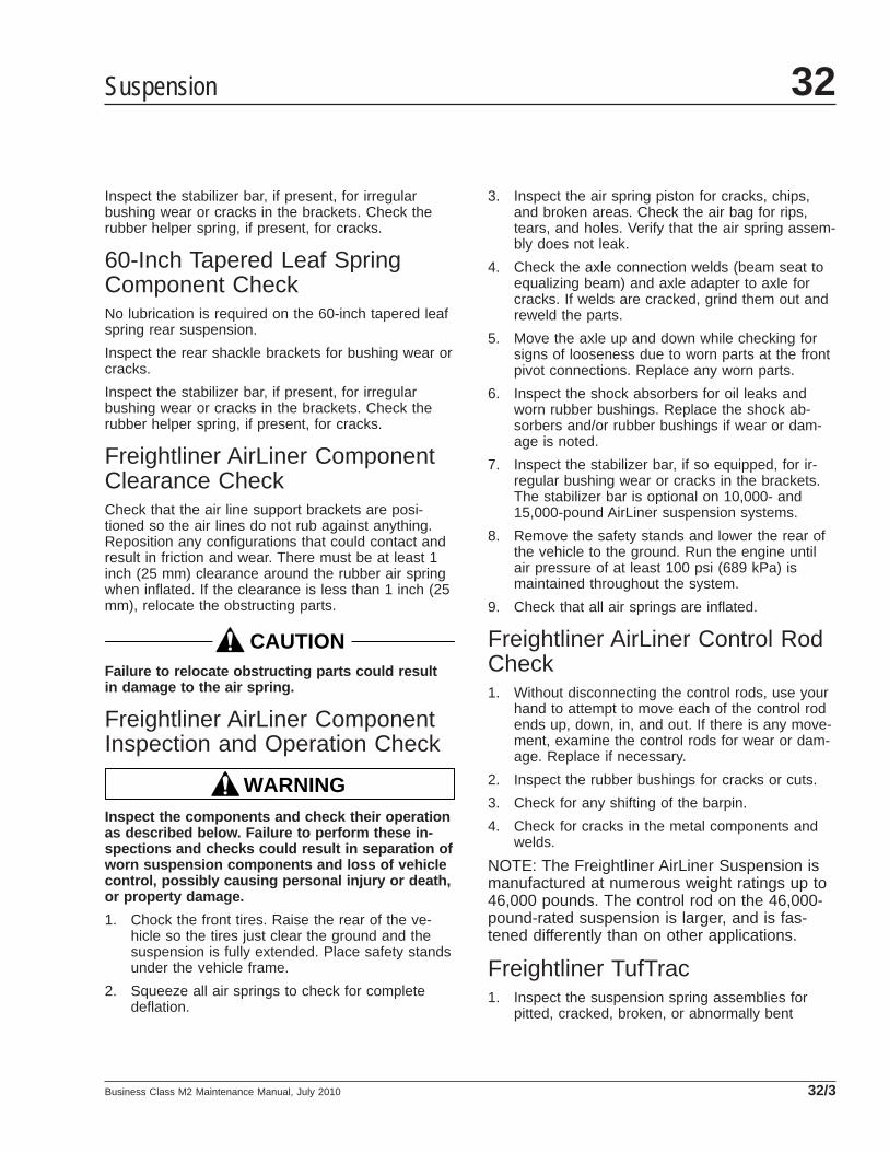
Inspect the stabilizer bar, if present, for irregularbushing wear or cracks in the brackets. Check therubber helper spring, if present, for cracks.
60-Inch Tapered Leaf SpringComponent CheckNo lubrication is required on the 60-inch tapered leafspring rear suspension.
Inspect the rear shackle brackets for bushing wear orcracks.
Inspect the stabilizer bar, if present, for irregularbushing wear or cracks in the brackets. Check therubber helper spring, if present, for cracks.
Freightliner AirLiner ComponentClearance CheckCheck that the air line support brackets are posi-tioned so the air lines do not rub against anything.Reposition any configurations that could contact andresult in friction and wear. There must be at least 1inch (25 mm) clearance around the rubber air springwhen inflated. If the clearance is less than 1 inch (25mm), relocate the obstructing parts.
CAUTIONFailure to relocate obstructing parts could resultin damage to the air spring.
Freightliner AirLiner ComponentInspection and Operation Check
WARNINGInspect the components and check their operationas described below. Failure to perform these in-spections and checks could result in separation ofworn suspension components and loss of vehiclecontrol, possibly causing personal injury or death,or property damage.
1. Chock the front tires. Raise the rear of the ve-hicle so the tires just clear the ground and thesuspension is fully extended. Place safety standsunder the vehicle frame.
2. Squeeze all air springs to check for completedeflation.
3. Inspect the air spring piston for cracks, chips,and broken areas. Check the air bag for rips,tears, and holes. Verify that the air spring assem-bly does not leak.
4. Check the axle connection welds (beam seat toequalizing beam) and axle adapter to axle forcracks. If welds are cracked, grind them out andreweld the parts.
5. Move the axle up and down while checking forsigns of looseness due to worn parts at the frontpivot connections. Replace any worn parts.
6. Inspect the shock absorbers for oil leaks andworn rubber bushings. Replace the shock ab-sorbers and/or rubber bushings if wear or dam-age is noted.
7. Inspect the stabilizer bar, if so equipped, for ir-regular bushing wear or cracks in the brackets.The stabilizer bar is optional on 10,000- and15,000-pound AirLiner suspension systems.
8. Remove the safety stands and lower the rear ofthe vehicle to the ground. Run the engine untilair pressure of at least 100 psi (689 kPa) ismaintained throughout the system.
9. Check that all air springs are inflated.
Freightliner AirLiner Control RodCheck1. Without disconnecting the control rods, use your
hand to attempt to move each of the control rodends up, down, in, and out. If there is any move-ment, examine the control rods for wear or dam-age. Replace if necessary.
2. Inspect the rubber bushings for cracks or cuts.
3. Check for any shifting of the barpin.
4. Check for cracks in the metal components andwelds.
NOTE: The Freightliner AirLiner Suspension ismanufactured at numerous weight ratings up to46,000 pounds. The control rod on the 46,000-pound-rated suspension is larger, and is fas-tened differently than on other applications.
Freightliner TufTrac1. Inspect the suspension spring assemblies for
pitted, cracked, broken, or abnormally bent
Suspension 32
Business Class M2 Maintenance Manual, July 2010 32/3
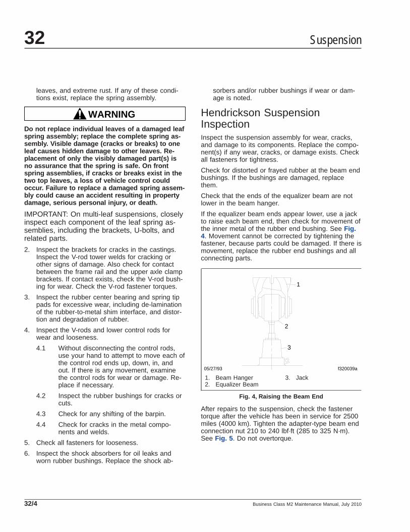
leaves, and extreme rust. If any of these condi-tions exist, replace the spring assembly.
WARNINGDo not replace individual leaves of a damaged leafspring assembly; replace the complete spring as-sembly. Visible damage (cracks or breaks) to oneleaf causes hidden damage to other leaves. Re-placement of only the visibly damaged part(s) isno assurance that the spring is safe. On frontspring assemblies, if cracks or breaks exist in thetwo top leaves, a loss of vehicle control couldoccur. Failure to replace a damaged spring assem-bly could cause an accident resulting in propertydamage, serious personal injury, or death.
IMPORTANT: On multi-leaf suspensions, closelyinspect each component of the leaf spring as-semblies, including the brackets, U-bolts, andrelated parts.
2. Inspect the brackets for cracks in the castings.Inspect the V-rod tower welds for cracking orother signs of damage. Also check for contactbetween the frame rail and the upper axle clampbrackets. If contact exists, check the V-rod bush-ing for wear. Check the V-rod fastener torques.
3. Inspect the rubber center bearing and spring tippads for excessive wear, including de-laminationof the rubber-to-metal shim interface, and distor-tion and degradation of rubber.
4. Inspect the V-rods and lower control rods forwear and looseness.
4.1 Without disconnecting the control rods,use your hand to attempt to move each ofthe control rod ends up, down, in, andout. If there is any movement, examinethe control rods for wear or damage. Re-place if necessary.
4.2 Inspect the rubber bushings for cracks orcuts.
4.3 Check for any shifting of the barpin.
4.4 Check for cracks in the metal compo-nents and welds.
5. Check all fasteners for looseness.
6. Inspect the shock absorbers for oil leaks andworn rubber bushings. Replace the shock ab-
sorbers and/or rubber bushings if wear or dam-age is noted.
Hendrickson SuspensionInspectionInspect the suspension assembly for wear, cracks,and damage to its components. Replace the compo-nent(s) if any wear, cracks, or damage exists. Checkall fasteners for tightness.
Check for distorted or frayed rubber at the beam endbushings. If the bushings are damaged, replacethem.
Check that the ends of the equalizer beam are notlower in the beam hanger.
If the equalizer beam ends appear lower, use a jackto raise each beam end, then check for movement ofthe inner metal of the rubber end bushing. See Fig.4. Movement cannot be corrected by tightening thefastener, because parts could be damaged. If there ismovement, replace the rubber end bushings and allconnecting parts.
After repairs to the suspension, check the fastenertorque after the vehicle has been in service for 2500miles (4000 km). Tighten the adapter-type beam endconnection nut 210 to 240 lbf·ft (285 to 325 N·m).See Fig. 5 . Do not overtorque.
f320039a05/27/93
1
2
3
1. Beam Hanger2. Equalizer Beam
3. Jack
Fig. 4, Raising the Beam End
Suspension32
Business Class M2 Maintenance Manual, July 201032/4

WARNINGInsufficient beam end fastener torque could causethe beam to separate from the axle. This willcause loss of vehicle control resulting in propertydamage, serious personal injury or death.
Hendrickson Leaf SpringAssembly Inspection1. Inspect the spring hangers for wear of the spring
pin holes, cams, and the spring hanger legs. SeeFig. 6 .
2. If equipped with the RTE series, the gap be-tween the rear (no. 2) spring hanger and the topspring leaf should measure at least 3/8 inch (9.5mm) in an unloaded condition.
If the measurement is less than 3/8 inch (9.5mm), install new rear (no. 3) extension hangers.Lubricate the bolt threads with SAE 20 oil.Tighten the 1/2–13 locknuts with hardenedwashers 85 lbf·ft (115 N·m).
3. Inspect the spring leaves for cracks, gouges,wear, or abnormal bends. The main (no. 1) andwrapper spring leaves (no. 2)—the top two
spring leaves—may be individually replaced. Ifequipped with the RTE series suspension, thefirst, second, and third spring leaves (the topthree spring leaves) may be individually re-placed. If a spring leaf is damaged below thesenumbers in a pack, replace the spring assembly.In addition, replace both spring assemblies toensure even spring deflection.
Hendrickson Radius RodBushing Check1. Without detaching the torque arms, use your
hand to attempt to move each of the radius-rodends up, down, in, and out. If there is any move-ment, replace the torque arm.
2. Inspect the rubber bushing ends. Replace thetorque arm if there are gaps between the rubberbushing and the pin or the outer steel sleeve, ifeither bushing end contacts a torque arm pinmounting bolt, if there are cracks in the bushing,or if part of the rubber bushing extends beyondthe outside diameter of the outer bushing sleeve.
Chalmers Suspension InspectionChock the front wheels to prevent the vehicle frommoving. Place the transmission in neutral and re-lease the spring or driveline brakes before inspectingthe rear suspension.
f320110a05/27/93
1
2
2
3 4
5
NOTE: Do not use the three-piece adapter without theintermediate tube.
1. Nut2. Adapter3. Intermediate Tube
4. Inner Metal of BeamEnd Bushing
5. Beam Hanger
Fig. 5, Three-Piece Adapter-Type Beam End Connection
f320112a05/27/93
1
2 3
4
A
A. Minimum gap of 3/8 inch (9.5 mm).1. Forward (no. 1) Spring Hanger2. Spring Eye Pin3. Rear (no. 2) Spring Hanger4. Rear (no. 3) Extension
Fig. 6, Unloaded RTE Spring Suspension
Suspension 32
Business Class M2 Maintenance Manual, July 2010 32/5
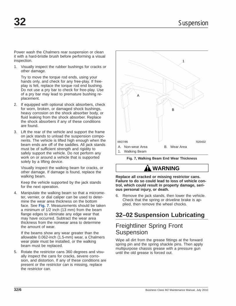
Power wash the Chalmers rear suspension or cleanit with a hard-bristle brush before performing a visualinspection.
1. Visually inspect the rubber bushings for cracks orother damage.
Try to move the torque rod ends, using yourhands only, and check for any free-play. If free-play is felt, replace the torque rod end bushing.Do not use a pry bar to check for free-play. Useof a pry bar may lead to premature bushing re-placement.
2. If equipped with optional shock absorbers, checkfor worn, broken, or damaged shock bushings,heavy corrosion on the shock absorber body, orfluid leaking from the shock absorber. Replacethe shock absorbers if any of these conditionsare found.
3. Lift the rear of the vehicle and support the frameon jack stands to unload the suspension compo-nents. The vehicle is lifted high enough when thebeam ends are off of the saddles. All jack standsmust be of sufficient strength and rigidity tosafely support the vehicle. Do not perform anywork on or around a vehicle that is supportedsolely by a lifting device.
Visually inspect the walking beam for cracks, orother damage. If damage is found, replace thewalking beam.
Keep the vehicle supported by the jack standsfor the next operation.
4. Manipulate the walking beam so that a microme-ter, vernier, or dial caliper can be used to deter-mine the wear area thickness on the bottomface. See Fig. 7 . Measurements should be takena minimum of 1/2 inch (13 mm) from the beamflange edges to eliminate any edge wear thatmay have occurred. Subtract the wear areathickness from the nonwear area to determinethe amount of wear.
If the beams show any wear greater than theallowable 0.062-inch (1.5-mm) wear, a Chalmerswear plate must be installed, or the walkingbeam must be replaced.
5. Rotate the restrictor cans 360 degrees and visu-ally inspect the cans for cracks, severe corro-sion, and distortion. If any of these conditions arepresent or the restrictor can is missing, replacethe restrictor can.
WARNINGReplace all cracked or missing restrictor cans.Failure to do so could lead to loss of vehicle con-trol, which could result in property damage, seri-ous personal injury, or death.
6. Remove the jack stands, then lower the vehicle.Check that the spring or driveline brake is ap-plied, then remove the wheel chocks.
32–02 Suspension Lubricating
Freightliner Spring FrontSuspensionWipe all dirt from the grease fittings at the forwardspring pin and the spring shackle pins. Then applymultipurpose chassis grease with a pressure gununtil the old grease is forced out.
09/27/95 f320432
1
A
B
A. Non-wear Area B. Wear Area1. Walking Beam
Fig. 7, Walking Beam End Wear Thickness
Suspension32
Business Class M2 Maintenance Manual, July 201032/6

Freightliner Spring RearSuspensionSingle AxleLubrication is not required on single-axle spring rearsuspensions.
Tandem Axle
CAUTIONIf the equalizer cap and tube assembly isequipped with a nonrelief grease fitting, excessivelubrication can damage the bushings.
Lubricate the equalizer cap and tube assembly bush-ings by applying multipurpose chassis grease at thepressure relief grease fitting. See Fig. 8 . Lubricatewith a hand gun or pressure gun until grease isforced out from the base of the pressure-relief fitting.
Hendrickson Equalizer BeamEnd Bushings and RubberCenter BushingsNo lubrication is required for the equalizer beam endbushings or equalizer beam rubber center bushings.
Hendrickson Spring Eye Pins,RT and RTE SeriesApply multipurpose chassis grease at the spring eyepin grease fitting, located on the inboard side of thespring eye pin, until clean grease appears at bothends of the spring eye pin. See Fig. 6 .
Freightliner TufTracThe TufTrac suspension is maintenance-free and de-signed so that lubrication is not required. There areno provisions for lubrication, and attempting to lubri-cate the suspension could shorten component life.
32–03 Suspension U-BoltTorque Checking
Check the U-bolt torque of both the front and rearaxles where applicable.
CAUTIONFailure to retorque the U-bolt nuts could result inspring breakage and abnormal tire wear.
1. Park the vehicle on a flat surface and apply theparking brakes. Chock the tires to prevent thevehicle from moving.
2. Check the U-bolt torque in a diagonal pattern.Set a click-type torque wrench to the highesttorque value for the fastener being checked. SeeTable 1 for U-bolt torque specifications. Turn thewrench in a clockwise motion (looking up) untilthe torque wrench clicks.
Spring Assembly U-Bolt High Nut Torque Values *
Size Torque: lbf·ft (N·m)
5/8–18
Stage 1: Hand-tightenStage 2: 60 (81)Stage 3: 200 (271)Stage 4: 180 to 230 (245 to 313)
3/4–16
Stage 1: Hand-tightenStage 2: 60 (81)Stage 3: 200 (271)Stage 4: 270 to 330 (367 to 449)
320020a05/27/93
1
1
A
A. Lubricate here.1. Cap and Tube Assembly Bushing
Fig. 8, Equalizer Assembly Lubrication
Suspension 32
Business Class M2 Maintenance Manual, July 2010 32/7

Spring Assembly U-Bolt High Nut Torque Values *
Size Torque: lbf·ft (N·m)
7/8–14
Stage 1: Hand-tightenStage 2: 60 (81)Stage 3: 200 (271)Stage 4: 420 to 500 (571 to 680)
1–14
Stage 1: Hand-tightenStage 2: 60 (81)Stage 3: 200 (271)Stage 4: 520 to 600 (707 to 816)
* Tighten in a diagonal pattern as shown in Fig. 9 .
Table 1, Spring Assembly U-Bolt High Nut TorqueValues
03/10/2011 f320783
1
2 3
4
Fig. 9, Tightening Pattern for U-Bolt High Nuts
Suspension32
Business Class M2 Maintenance Manual, July 201032/8

Title of Maintenance Operation (MOP) MOP Number
Draw Key Nut Torque Checking . . . . . . . . . . . . . . . . . . . . . . . . . . . . . . . . . . . . . . . . . . . . . . . . . . . . . . . 33–03
Kingpin Lubricating. . . . . . . . . . . . . . . . . . . . . . . . . . . . . . . . . . . . . . . . . . . . . . . . . . . . . . . . . . . . . . . . . 33–01
Tie Rod End Inspecting . . . . . . . . . . . . . . . . . . . . . . . . . . . . . . . . . . . . . . . . . . . . . . . . . . . . . . . . . . . . . 33–04
Tie Rod End Lubricating. . . . . . . . . . . . . . . . . . . . . . . . . . . . . . . . . . . . . . . . . . . . . . . . . . . . . . . . . . . . . 33–02
Wheel End Inspection and Maintenance, 6,000-Pound and 8,000-Pound SteerAxles with Oil-Lubricated Hubs. . . . . . . . . . . . . . . . . . . . . . . . . . . . . . . . . . . . . . . . . . . . . . . . . . . . . . . . 33–05
Front Axle 33Index, Alphabetical
Business Class M2 Maintenance Manual, July 2009

33–01 Kingpin Lubricating
Sealed and Easy Steer™
Kingpins—Axles With UnitizedWheel EndsNOTE: This procedure applies to 921, 931, 932,933, 934, 941, 942, 943, 951, 961, 963, 966,967, 971, and 975 Series Easy Steer sealedfront axles. Refer to the identification tag on thefront of the axle beam.
On sealed and Easy Steer Plus™ front axles, thegrease fittings are on the top and bottom kingpincaps of the knuckle.
1. Shut off the engine, apply the brakes, and chockthe rear tires.
2. Make sure the tires touch the ground. Do notraise the vehicle.
3. Clean off all grease fittings prior to lubrication.
IMPORTANT: Meritor recognizes that industrytrends are moving toward increased selectionand usage of synthetic grease in vehicle mainte-nance. However, some seals are known to ex-pand when in contact with synthetic grease.Consult your local Meritor representative forsynthetic grease application references beforeusing any synthetic grease when performingaxle service and maintenance.
4. Using a multipurpose grease, NLGI grade 1 or 2,lubricate the kingpins through the grease fittingson the top and bottom of the knuckle. SeeFig. 1 .
5. Apply lubricant until new lubricant comes fromthe thrust bearing seal and the upper shim pack.
6. Remove the chocks from the tires.
Easy Steer™ Kingpins—AxlesWith Unitized Wheel EndsNOTE: This procedure applies to Easy SteerPlus™ MFS 10-2015-N and MFS 12-2015-Nsealed front axles. Refer to the identification tagon the front of the axle beam.
On Easy Steer Plus front axles, the grease fittingsare on the top and bottom kingpin caps of theknuckle.
1. Shut off the engine, apply the brakes, and chockthe rear tires.
2. Make sure the tires touch the ground. Do notraise the vehicle.
3. Clean off all grease fittings prior to lubrication.
IMPORTANT: Meritor recognizes that industrytrends are moving toward increased selectionand usage of synthetic grease in vehicle mainte-nance. However, some seals are known to ex-pand when in contact with synthetic grease.Consult your local Meritor representative forsynthetic grease application references beforeusing any synthetic grease when performingaxle service and maintenance.
4. Using a multipurpose grease, NLGI grade 1 or 2,lubricate the kingpins through the grease fittingson the top and bottom of the knuckle. SeeFig. 2 .
5. Force lubricant into the upper and lower kingpingrease fitting caps until new lubricant flows frombetween the upper axle beam end and the
10/10/2001 f330185
1
A
A. Apply lubricant until new lubricant comes from theseareas.
1. Grease Fitting
Fig. 1, Sealed, Easy Steer Kingpin Lubrication
Front Axle 33
Business Class M2 Maintenance Manual, July 2009 33/1

knuckle, and between the lower axle beam endand the knuckle. See Fig. 2 .
6. Remove the chocks from the tires.
33–02 Tie Rod End LubricatingThis procedure applies to all tie rod ends on Meritornondrive steering axles.
1. Park the vehicle with the wheels in the straight-ahead position. Turn off the engine, apply thebrakes, and chock the rear tires.
2. Wipe clean the zerk fitting and the seal or boot.
NOTE: Synthetic lubricants are not approved fortie rod end lubrication.
3. Using a grease gun, apply a multipurposegrease, NLGI grade 1 or 2, to the zerk fitting untilall the old grease is purged from the boot. Dis-colored old grease should come out of the purgeholes near the boot crimp or bellows area.
Apply grease until all the old grease is purgedfrom the boot.
NOTE: If using an air pressure grease gun, donot exceed 150 psi (1035 kPa).
4. If the tie rod end is designed for lube service andit does not accept grease, perform the followingsubsteps.
4.1 Remove the zerk fitting.
4.2 Inspect the threaded zerk fitting hole inthe tie rod end, and remove any obstruc-tions.
4.3 Install a new zerk fitting.
4.4 Apply lubrication to the new zerk fitting.
5. Remove the chocks from the tires.
33–03 Draw Key Nut TorqueChecking
Axles With Unitized Wheel EndsCheck the torque of the nut that holds the draw keyon the side of the knuckle. The torque should be 30to 45 lbf·ft (41 to 61 N·m). See Fig. 3 .
33–04 Tie Rod End InspectingIMPORTANT: If the tie rod end boot is torn ormissing, replace the entire tie rod end. Do notreplace the boot only.
1. Shut off the engine, apply the brakes, and chockthe rear tires.
2. Check the tie rod boot for cracks, tears, or otherdamage. If the tie rod boot is damaged, replacethe entire tie rod end.
3. Grasp by hand (or use a pipe wrench with jawprotectors to avoid gouging the cross tube) and
10/11/2001 f330184
1A
1
A. Apply lubricant until new lubricant comes from theseareas.
1. Grease Fitting
Fig. 2, Sealed, Easy Steer Plus Kingpin Lubrication
10/11/2001 f330186
Fig. 3, Draw Key Nut
Front Axle33
Business Class M2 Maintenance Manual, July 200933/2

slightly rotate the cross tube toward the front ofthe vehicle and then slightly toward the rear.Then center the cross tube between the stop po-sitions. If the cross tube does not rotate in eitherdirection, replace both tie rod ends.
4. Position yourself directly below the ball studsocket. Using both hands, grab the end as closeto the socket as possible, no more than 6 inches(15.2 cm) from the end. Firmly apply about 100pounds of hand pressure in an up and down mo-tion several times. When moving the assembly,check for any movement at both tie rod ends.See Fig. 4 .
If any movement is detected at one tie rod end,replace both tie rod ends. Always replace tie rodends in pairs, even if only one tie rod end isdamaged.
CAUTIONDo not attempt to straighten a bent cross tube.Doing so could result in damage to the axle. Besure to replace the cross tube with an originalequipment cross tube with the same length, diam-eter, and thread size as the existing cross tube.
5. Check the cross tube for cracks or other dam-age. If the cross tube is bent or damaged, re-place the cross tube.
6. Check the clamps for damage. If a clamp isdamaged, replace the clamp. Replace the entirecross tube assembly if either clamp is welded tothe cross tube.
7. Check for proper installation of the tie rod endclamp to the cross tube. Make sure that the tierod ends are threaded in the cross tube past theclamps and the slots at the cross tube ends.
8. Check the zerk fittings for damage. If a zerk fit-ting is damaged, replace it.
Some tie rod ends have no zerk fittings becausethey are not greaseable. Do not install a zerkfitting on a nongreaseable tie rod end.
9. Check that the cotter pin is in place. If it is not,tighten the tie rod end nut to one of the followingspecs depending on the size of the stud.
• 7/8–14, 160 to 300 lbf·ft (217 to 406 N·m)
• 1–14, 250 to 450 lbf·ft (339 to 610 N·m)
• 1-1/8–12, 350 to 650 lbf·ft (475 to 881N·m)
• 1-1/4–12, 500 to 675 lbf·ft (678 to 915N·m)
10. Check the steering arm bolts for a minimumtorque of 300 lbf·ft (406 N·m). If the steering armbolt torque has fallen below this specification,remove the bolt, clean all the threads, and applynew Loctite® 680. Tighten the bolt 300 to 450lbf·ft (406 to 610 N·m).
11. Remove the chocks from the tires.
33–05 Wheel End Inspectionand Maintenance, 6,000-Pound and 8,000-PoundSteer Axles with Oil-Lubricated Hubs
Periodic inspection and maintenance of wheel endson 6,000-pound and 8,000-pound steer axles is es-sential to sound wheel bearing performance. Checkfor leaks at the oil seal and hub, and inspect the lu-bricant per the maintenance intervals provided inGroup 00 of this manual.
Oil Seal Leak CheckCheck for evidence of oil leakage at the oil seal. If aleak is found, replace the seal. See Section 33.02 ofthe Business Class® M2 Workshop Manual for in-structions.
10/10/2001 f330195
Fig. 4, Check Movement of Tie Rod End
Front Axle 33
Business Class M2 Maintenance Manual, July 2009 33/3

Hub Cap Leak InspectionCheck for evidence of oil leakage between the hubcap, gasket and hub surface. If leakage is evident,replace the gasket with a new one. See Section33.01, Subject 100 of the Business Class® M2Workshop Manual for instructions.
Check for a missing hub cap fill plug or vent plug.See Fig. 5 . Replace any missing parts. If a vent plugis missing, the oil quality is compromised and mustbe replaced. See Section 33.01, Subject 100 of theBusiness Class® M2 Workshop Manual forinstructions.
Lubricant InspectionRotate the hub so that the fill plug is down, and draina small sample of hub oil into a plastic container thatis free of debris, especially any metallic particles.Then use a magnet to probe the sample. Notewhether there is substantial metallic debris present,and compare the oil color to new approved oil. Ac-ceptable oil will have a color similar to new oil andhave no water or metal contaminants.
If the oil is not acceptable, inspect the bearings fordamage. Replace the bearings as needed, and installthe hub per Section 33.01, Subject 100 of theBusiness Class® M2 Workshop Manual.
If the oil is acceptable, check the oil level. If it is notfull (see Fig. 5 ), fill it to the bottom of the vent plughole with approved lubricant (see Table 1 ).
Lubricant Specifications, Over-the-Road ServiceApplications
Lubricant Type Lubricant SAEViscosity Grade
Synthetic Drive Axle Lubricants orEquivalent with SAE SpecificationJ2360 or Military Specification MIL-L-2105E
75W-90
Table 1, Lubricant Specifications, Over-the-RoadService Applications
f330247a
A
1
2
01/05/2009
A. Hub Cavity Full1. Vent Plug2. Magnetic Drain/Fill Plug
Fig. 5, Stemco Hub Cap
Front Axle33
Business Class M2 Maintenance Manual, July 200933/4

Title of Maintenance Operation (MOP) MOP Number
Axle Breather Checking . . . . . . . . . . . . . . . . . . . . . . . . . . . . . . . . . . . . . . . . . . . . . . . . . . . . . . . . . . . . . 35–02
Axle Lubricant Changing and Magnetic Plug Cleaning . . . . . . . . . . . . . . . . . . . . . . . . . . . . . . . . . . . . . . . 35–03
Axle Lubricant Level Checking . . . . . . . . . . . . . . . . . . . . . . . . . . . . . . . . . . . . . . . . . . . . . . . . . . . . . . . . 35–01
Rear Axle 35Index, Alphabetical
Business Class M2 Maintenance Manual, December 2001

35–01 Axle Lubricant LevelChecking
CAUTIONFailure to keep the rear axle filled to the properlevel with the recommended lubricant can result inrear axle damage.
1. Clean the oil fill hole plug located in the carrier orthe side of the axle housing and the area sur-rounding it. See Fig. 1 . Remove the plug.
NOTE: Some Meritor axles have a small tappedand plugged hole located below the housing oilfill hole. This smaller hole is for the lubricanttemperature sensor only and must not be usedas a fill or level hole.
2. When the vehicle is on level ground, the lubri-cant must be level with the bottom of the oil fillhole. If low, add lubricant. See Table 1 for ap-proved axle lubricants and see Table 2 orTable 3 for axle capacities.
35–02 Axle Breather CheckingThe axle housing breather must remain clean. SeeFig. 1 . When the axle lubricant level is checked,
check that the axle breather is open. Check moreoften under poor operating conditions. If the breatheris plugged, clean it or replace it as needed.
Meritor Drive Axle Recommended Lubricant
Lubricant Type Ambient Temperature Viscosity Grade Meritor Specification
Hypoid Gear Oil API ServiceClassification GL–5
10°F (–12.2°C) and up* 85W–140 0–76–A
–15°F (–26.1°C) and up* 80W–90 0–76–D
–40°F (–40°C) and up* 75W–90 0–76–E
–40°F (–40°C) to 35°F (2°C) 75W 0–76–J
–40°F (–40°C) and up* 75W–140 0–76–L
Synthetic Gear Oil–40°F (–40°C) and up* 75W–90 0–76–N
–40°F (–40°C) and up* 75W–140 0–76–M* There is no upper limit on the ambient temperature, but axle sump temperature must never exceed 250° (121°C).
Table 1, Meritor Drive Axle Recommended Lubricant
06/07/94 f350062a
1
2 3
1. Axle Housing Breathers2. Carrier Oil Fill Plugs3. Interaxle Differential
Fig. 1, Fill Hole Plug and Axle Housing BreatherLocations
Rear Axle 35
Business Class M2 Maintenance Manual, December 2001 35/1
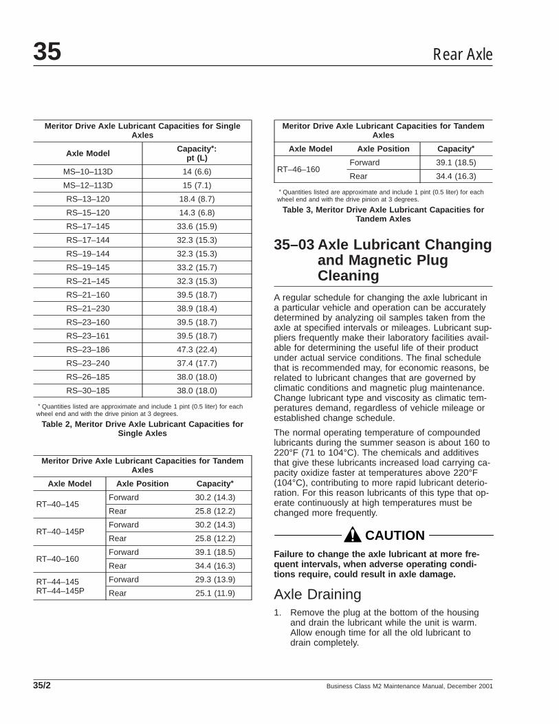
Meritor Drive Axle Lubricant Capacities for SingleAxles
Axle Model Capacity *:pt (L)
MS–10–113D 14 (6.6)
MS–12–113D 15 (7.1)
RS–13–120 18.4 (8.7)
RS–15–120 14.3 (6.8)
RS–17–145 33.6 (15.9)
RS–17–144 32.3 (15.3)
RS–19–144 32.3 (15.3)
RS–19–145 33.2 (15.7)
RS–21–145 32.3 (15.3)
RS–21–160 39.5 (18.7)
RS–21–230 38.9 (18.4)
RS–23–160 39.5 (18.7)
RS–23–161 39.5 (18.7)
RS–23–186 47.3 (22.4)
RS–23–240 37.4 (17.7)
RS–26–185 38.0 (18.0)
RS–30–185 38.0 (18.0)
* Quantities listed are approximate and include 1 pint (0.5 liter) for eachwheel end and with the drive pinion at 3 degrees.
Table 2, Meritor Drive Axle Lubricant Capacities forSingle Axles
Meritor Drive Axle Lubricant Capacities for TandemAxles
Axle Model Axle Position Capacity *
RT–40–145Forward 30.2 (14.3)
Rear 25.8 (12.2)
RT–40–145PForward 30.2 (14.3)
Rear 25.8 (12.2)
RT–40–160Forward 39.1 (18.5)
Rear 34.4 (16.3)
RT–44–145RT–44–145P
Forward 29.3 (13.9)
Rear 25.1 (11.9)
Meritor Drive Axle Lubricant Capacities for TandemAxles
Axle Model Axle Position Capacity *
RT–46–160Forward 39.1 (18.5)
Rear 34.4 (16.3)
* Quantities listed are approximate and include 1 pint (0.5 liter) for eachwheel end and with the drive pinion at 3 degrees.
Table 3, Meritor Drive Axle Lubricant Capacities forTandem Axles
35–03 Axle Lubricant Changingand Magnetic PlugCleaning
A regular schedule for changing the axle lubricant ina particular vehicle and operation can be accuratelydetermined by analyzing oil samples taken from theaxle at specified intervals or mileages. Lubricant sup-pliers frequently make their laboratory facilities avail-able for determining the useful life of their productunder actual service conditions. The final schedulethat is recommended may, for economic reasons, berelated to lubricant changes that are governed byclimatic conditions and magnetic plug maintenance.Change lubricant type and viscosity as climatic tem-peratures demand, regardless of vehicle mileage orestablished change schedule.
The normal operating temperature of compoundedlubricants during the summer season is about 160 to220°F (71 to 104°C). The chemicals and additivesthat give these lubricants increased load carrying ca-pacity oxidize faster at temperatures above 220°F(104°C), contributing to more rapid lubricant deterio-ration. For this reason lubricants of this type that op-erate continuously at high temperatures must bechanged more frequently.
CAUTIONFailure to change the axle lubricant at more fre-quent intervals, when adverse operating condi-tions require, could result in axle damage.
Axle Draining1. Remove the plug at the bottom of the housing
and drain the lubricant while the unit is warm.Allow enough time for all the old lubricant todrain completely.
Rear Axle35
Business Class M2 Maintenance Manual, December 200135/2

2. Clean the drain plugs. For magnetic drain plugs,a piece of key stock or any other convenientsteel slug may be used to short the two magneticpoles and divert the magnetic field.
NOTE: Meritor recommends using magneticplugs with elements having a minimum pickupcapacity of two pounds (one kilogram) of low-carbon steel in plate or bar form. Magnets willrapidly lose effectiveness as collected materialbridges the gap between the two poles. Cleanor change the plugs before this occurs. It maybe necessary to clean or change the plugs oneor more times between lubrication change inter-vals.
3. After cleaning the drain plugs, install and tightenthe plugs 35 lbf·ft (47 N·m).
Axle Filling1. With the vehicle on a level surface, fill the axle
housings to the bottom of the oil fill hole (in thecarrier or housing) with lubricant. See Table 1 forapproved axle lubricants and see Table 2 orTable 3 for axle capacities.
NOTE: Some Meritor axles have a small tappedand plugged hole located below the housing oilfill hole. This smaller hole is for the lubricanttemperature sensor only and must not be usedas a fill or level hole.
2. Install the fill hole plug and tighten it 35 lbf·ft (47N·m).
3. After filling the carrier and housing assembly withlubricant, drive the vehicle unloaded for one ortwo miles (two or three kilometers) at speeds notto exceed 25 mph (40 km/h) to thoroughly circu-late the lubricant throughout the assembly.
Rear Axle 35
Business Class M2 Maintenance Manual, December 2001 35/3
Title of Maintenance Operation (MOP) MOP Number
Wheel Nut Checking. . . . . . . . . . . . . . . . . . . . . . . . . . . . . . . . . . . . . . . . . . . . . . . . . . . . . . . . . . . . . . . . 40–01
Wheels and Tires 40Index, Alphabetical
Business Class M2 Maintenance Manual, December 2001
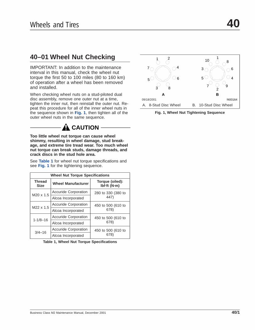
40–01 Wheel Nut CheckingIMPORTANT: In addition to the maintenanceinterval in this manual, check the wheel nuttorque the first 50 to 100 miles (80 to 160 km)of operation after a wheel has been removedand installed.
When checking wheel nuts on a stud-piloted dualdisc assembly, remove one outer nut at a time,tighten the inner nut, then reinstall the outer nut. Re-peat this procedure for all of the inner wheel nuts inthe sequence shown in Fig. 1 , then tighten all of theouter wheel nuts in the same sequence.
CAUTIONToo little wheel nut torque can cause wheelshimmy, resulting in wheel damage, stud break-age, and extreme tire tread wear. Too much wheelnut torque can break studs, damage threads, andcrack discs in the stud hole area.
See Table 1 for wheel nut torque specifications andsee Fig. 1 for the tightening sequence.
Wheel Nut Torque Specifications
ThreadSize Wheel Manufacturer Torque (oiled):
lbf·ft (N·m)
M20 x 1.5Accuride Corporation 280 to 330 (380 to
447)Alcoa Incorporated
M22 x 1.5Accuride Corporation 450 to 500 (610 to
678)Alcoa Incorporated
1-1/8–16Accuride Corporation 450 to 500 (610 to
678)Alcoa Incorporated
3/4–16Accuride Corporation 450 to 500 (610 to
678)Alcoa Incorporated
Table 1, Wheel Nut Torque Specifications
09/18/2001
A Bf400164
110 8
63
5 4
92
7
1 2
4
6
7
5
83
A. 8-Stud Disc Wheel B. 10-Stud Disc Wheel
Fig. 1, Wheel Nut Tightening Sequence
Wheels and Tires 40
Business Class M2 Maintenance Manual, December 2001 40/1

Title of Maintenance Operation (MOP) MOP Number
Driveline Inspecting . . . . . . . . . . . . . . . . . . . . . . . . . . . . . . . . . . . . . . . . . . . . . . . . . . . . . . . . . . . . . . . . 41–01
Driveline Lubricating. . . . . . . . . . . . . . . . . . . . . . . . . . . . . . . . . . . . . . . . . . . . . . . . . . . . . . . . . . . . . . . . 41–02
Driveline 41Index, Alphabetical
Business Class M2 Maintenance Manual, December 2001

41–01 Driveline Inspecting
Driveline Inspection
WARNINGDo not service or inspect a driveshaft with the en-gine running. A rotating driveshaft can cause seri-ous personal injury.
Loose end yokes, excessive radial looseness, slipspline radial looseness, bent shaft tubing, or missingplugs in the slip yoke can cause universal joint andbearing defects.
See Fig. 1 for an illustration of the ArvinMeritor™
Full-Round driveline. See Fig. 2 for an illustration ofthe ArvinMeritor™ Easy Service™ or 1/2 Rounddriveline.
1. Check the output and input end yokes on boththe transmission and axle for axial looseness.Refer to the axle or transmission manufacturer’sservice information for the correct specifications.
If loose, disconnect the driveshaft. For instruc-tions, see Group 41 of the Business Class® M2Workshop Manual. Tighten the end yoke retain-ing nut to the proper specification. Refer to theaxle or transmission manufacturer’s service infor-mation for the correct specifications.
2. Inspect for worn universal joints. Apply a verticalforce of about 50 pounds to the driveline nearthe universal joints. If there is any movement,replace the universal joint. For instructions, seeGroup 41 of the Business Class® M2 WorkshopManual.
3. Examine the slip yoke spline for excessive radialmovement. See Fig. 3 . If excessive radial loose-ness exists between the slip yoke and the tubeshaft, replace the slip yoke and the tube shaft.For instructions, see Group 41 of the BusinessClass® M2 Workshop Manual.
4. Examine the shaft for damaged or bent tubing.Carefully remove any foreign material, such asmud or dirt on the shaft.
41–02 Driveline Lubricating
Driveline LubricationThe Full-Round and Easy Service drivelines requireperiodic lubrication of the universal joints and slip
09/19/2001 f410483
Fig. 1, Full-Round Driveline
09/19/2001 f410484
Fig. 2, Easy Service (1/2 Round) Driveline
f41048609/19/2001
Fig. 3, Examine the Slip Yoke Spline
Driveline 41
Business Class M2 Maintenance Manual, December 2001 41/1

yoke splines. See Fig. 4 for the areas that need lu-brication. See Table 1 for approved lubricants.
Approved Lubricants
Lubricant and Specification Lubricant Brands
Universal joint, slip joint, and spline greasemust meet ArvinMeritor Specification O–634–B(NLGI Grade No. 2, Lithium 12-HydroxyStearate with Molybdenum Disulfide)
Phillips Petroleum Philube MW–EP2 Grease
Exxon 5160
Amalie All Purpose Grease with Moly–L1–2M
Shell Super Duty Special FF
Marathon Maralube Molycode 529
Shell Moly Poly Grease
Kendall L424 Grease
Amoco Super Chassis Grease
Ford Specification M1C–75B or part number PN™C1AZ 19590
Table 1, Approved Lubricants
09/19/2001 f410485
Fig. 4, Lubrication Areas for Full-Round and EasyService Drivelines
Driveline41
Business Class M2 Maintenance Manual, December 200141/2

Title of Maintenance Operation (MOP) MOP Number
Air Brake Inspecting and Leak Testing. . . . . . . . . . . . . . . . . . . . . . . . . . . . . . . . . . . . . . . . . . . . . . . . . . . 42–13
Air Brake System Valve Inspecting . . . . . . . . . . . . . . . . . . . . . . . . . . . . . . . . . . . . . . . . . . . . . . . . . . . . . 42–01
Air Dryer AD–9, AD–IP, AD–IS/DRM Checking. . . . . . . . . . . . . . . . . . . . . . . . . . . . . . . . . . . . . . . . . . . . . 42–10
Bendix AD–9 Air Dryer Desiccant Replacing . . . . . . . . . . . . . . . . . . . . . . . . . . . . . . . . . . . . . . . . . . . . . . 42–02
Bendix AD–IP Air Dryer Desiccant Replacing. . . . . . . . . . . . . . . . . . . . . . . . . . . . . . . . . . . . . . . . . . . . . . 42–05
Bendix AD–IS Air Dryer Desiccant Replacing. . . . . . . . . . . . . . . . . . . . . . . . . . . . . . . . . . . . . . . . . . . . . . 42–09
Bendix Hydro-Max® Brake System Inspecting . . . . . . . . . . . . . . . . . . . . . . . . . . . . . . . . . . . . . . . . . . . . . 42–16
Bosch Hydraulic Brake System Inspecting. . . . . . . . . . . . . . . . . . . . . . . . . . . . . . . . . . . . . . . . . . . . . . . . 42–04
Brake Inspecting . . . . . . . . . . . . . . . . . . . . . . . . . . . . . . . . . . . . . . . . . . . . . . . . . . . . . . . . . . . . . . . . . . 42–15
Brake Lines and Fittings Inspecting, Hydraulic Brakes . . . . . . . . . . . . . . . . . . . . . . . . . . . . . . . . . . . . . . . 42–11
Brake Pedal Linkage and Mounting Plate Inspecting . . . . . . . . . . . . . . . . . . . . . . . . . . . . . . . . . . . . . . . . 42–12
Foot-Control Valve, E-6, Inspecting and Lubricating. . . . . . . . . . . . . . . . . . . . . . . . . . . . . . . . . . . . . . . . . 42–14
Governor D–2A Checking. . . . . . . . . . . . . . . . . . . . . . . . . . . . . . . . . . . . . . . . . . . . . . . . . . . . . . . . . . . . 42–03
Haldex and Gunite Slack Adjuster Lubricating . . . . . . . . . . . . . . . . . . . . . . . . . . . . . . . . . . . . . . . . . . . . . 42–06
Meritor Camshaft Bracket Lubricating . . . . . . . . . . . . . . . . . . . . . . . . . . . . . . . . . . . . . . . . . . . . . . . . . . . 42–07
Meritor Slack Adjuster Lubricating. . . . . . . . . . . . . . . . . . . . . . . . . . . . . . . . . . . . . . . . . . . . . . . . . . . . . . 42–08
Brakes 42Index, Alphabetical
Business Class M2 Maintenance Manual, January 2010

42–01 Air Brake System ValveInspecting
IMPORTANT: There is no scheduled (Bendix) airvalve maintenance that requires disassembly ofthe valve within the warranty period. If the valvedoes not function within the warranty period, donot disassemble the part as this will void thewarranty.
See the following maintenance operations forinformation about Bendix air valve maintenance.
42–02 Bendix AD–9 Air DryerDesiccant Replacing
IMPORTANT: For vehicles equipped with an oil-coalescing air dryer desiccant cartridge, replacethe cartridge once a year, regardless of mileage.
1. Park the vehicle on a level surface, apply theparking brakes, and chock the tires.
2. Completely drain all air reservoirs. Air pressuregauges should read 0 psi (0 kPa).
IMPORTANT: The compressor discharge linemay contain residual air pressure.
3. Identify, tag, and disconnect the three air linesfrom the end cover.
4. Disconnect the harness connector from theheater and thermostat assembly.
5. Loosen the capscrew that secures the uppermounting bracket strap.
6. Remove the two capscrews that sencure the airdryer to the lower mounting bracket. Mark theposition of the mounting bracket to the end coverand mark the capscrews to ease installation.
7. Remove the upper mounting bracket strap cap-screw, and remove the air dryer from the vehicle.
8. Place the air dryer on a bench and remove theremaining six capscrews, 12 washers, six nuts,and the air dryer housing. See Fig. 1 . Discardthe nuts. Remove the end-cover-to-housingO-ring.
9. Clamp the desiccant cartridge in a vise.
WARNINGClamping the end cover or housing in a vise couldseriously compromise the air dryer’s ability tohold air pressure, which could cause a failure inthe brake system, resulting in property damage,personal injury, or death.
10. Twist the end cover counterclockwise to releasethe cartridge from the end cover. Rotate the endcover until it completely separates from the des-iccant cartridge.
NOTE: A substantial torque, up to 50 lbf·ft (68N·m), may be necessary to remove the desic-cant cartridge.
11. Remove and discard desiccant cartridge O-rings.
NOTICEDirt or obstructions in the O-ring grooves cancause an O-ring failure that will result in an airleak.
12. Lubricate new O-rings with grease supplied inthe kit and install them in the end cover.
13. Install the desiccant cartridge on the end cover.Turn the cartridge clockwise until the desiccantcartridge makes contact with the end cover.
14. Place the desiccant cartridge in a vise, and turnthe end cover clockwise an additional 180 to 225degrees to fully tighten the desiccant cartridge tothe end cover.
NOTE: Desiccant cartridge torque should notexceed 50 lbf·ft (68 N·m).
15. Place the housing over the desiccant cartridgeand align the mounting holes with the end cover.
16. Install the six bolts, 12 washers, and six newnuts. Torque the nuts in a star pattern 270 to 385lbf·in (3060 to 4340 N·cm). See Fig. 2 .
17. Install the air dryer on the lower mountingbracket. Install the two previously marked bolts,four washers, and two new nuts. Torque the tworemaining nuts 270 to 385 lbf·in (3060 to 4340N·cm). Install the bolt, two washers, and a newnut in the upper mounting bracket strap. Torquethe upper mounting bracket strap nut 80 to 120lbf·in (904 to 1356 N·cm).
Brakes 42
Business Class M2 Maintenance Manual, January 2010 42/1
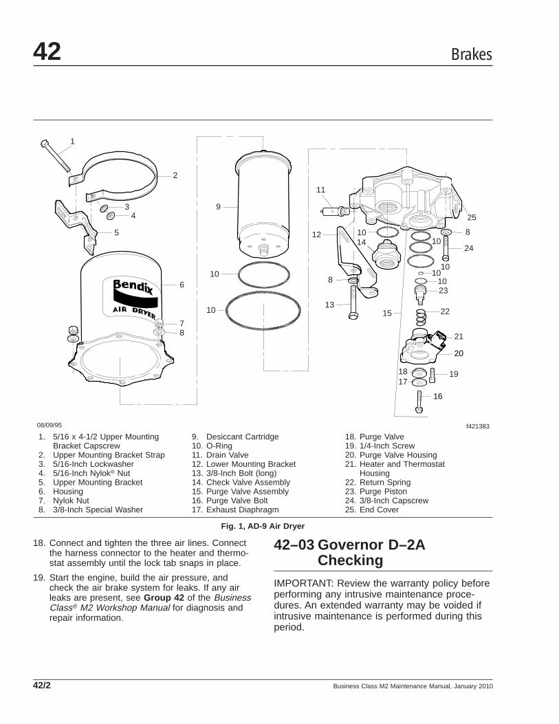
18. Connect and tighten the three air lines. Connectthe harness connector to the heater and thermo-stat assembly until the lock tab snaps in place.
19. Start the engine, build the air pressure, andcheck the air brake system for leaks. If any airleaks are present, see Group 42 of the BusinessClass® M2 Workshop Manual for diagnosis andrepair information.
42–03 Governor D–2AChecking
IMPORTANT: Review the warranty policy beforeperforming any intrusive maintenance proce-dures. An extended warranty may be voided ifintrusive maintenance is performed during thisperiod.
08/09/95 f421383
1
2
34
5
9
10
11
12
13
14
15
1718 19
21
22
23
24
25
10
1010
1010
106
78
8
8
20
16
1. 5/16 x 4-1/2 Upper MountingBracket Capscrew
2. Upper Mounting Bracket Strap3. 5/16-Inch Lockwasher4. 5/16-Inch Nylok® Nut5. Upper Mounting Bracket6. Housing7. Nylok Nut8. 3/8-Inch Special Washer
9. Desiccant Cartridge10. O-Ring11. Drain Valve12. Lower Mounting Bracket13. 3/8-Inch Bolt (long)14. Check Valve Assembly15. Purge Valve Assembly16. Purge Valve Bolt17. Exhaust Diaphragm
18. Purge Valve19. 1/4-Inch Screw20. Purge Valve Housing21. Heater and Thermostat
Housing22. Return Spring23. Purge Piston24. 3/8-Inch Capscrew25. End Cover
Fig. 1, AD-9 Air Dryer
Brakes42
Business Class M2 Maintenance Manual, January 201042/2

Every 12 months, 100,000 miles (160 900 km), or3600 operating hours, perform the operational testbelow.
Operational Test1. Start the vehicle engine, build air pressure in the
brake system, and check the pressure registeredby a dash or test gauge at the time the governorcuts-out, stopping the compression of air by thecompressor. Cut-out pressure should be in ac-cordance with the pressure setting of the piecenumber being used. Common cut-out pressuresare 125 to 135 psi (862 to 931 kPa). With theengine still running, make a series of brake appli-cations to reduce the air pressure, and observeat what pressure the governor cuts-in the com-pressor. As in the case of cut-out pressure, cut-inpressure should be in accordance with the pres-sure setting of the piece number being used.Cut-in pressure is 105 psi (724 kPa).
NOTE: If the governor cover is marked nonad-justable, and the adjusting stem has beensheared off, this is a non-serviceable governorand it must be replaced with a new or remanu-factured unit.
2. Never condemn or adjust the governor pressuresettings unless they’re checked with an accuratetest gauge or a dash gauge that’s registering ac-
curately. If the pressure settings of the D-2 gov-ernor are inaccurate or it’s necessary that theybe changed, the adjustment procedure follows.
2.1 Remove the top cover from the governor.
2.2 Loosen the adjusting screw locknut.
2.3 To raise the pressure setting, turn the ad-justing screw counterclockwise; to lowerthe setting, turn the screw clockwise. Becareful not to overadjust. Each 1/4 turn ofthe adjusting screw raises or lowers thepressure setting approximately 4 psi (28kPa).
2.4 When proper adjustment is obtained,tighten the adjusting screw locknut, andinstall the top cover. The pressure rangebetween cut-in and cut-out is not adjust-able.
Cut-In PositionApply soap solution around the cover and to the ex-haust port. Slight bubble leakage is permitted. Exces-sive leakage indicates a faulty inlet valve or faultylower piston O-ring.
Cut-Out PositionApply soap solution around the cover and to the ex-haust port. Slight bubble leakage is permitted. Exces-sive leakage indicates a faulty exhaust valve seat,exhaust stem O-ring, or O-ring at the top of thepiston.
If the governor does not function as described, or ifleakage is excessive, it is recommended that it bereplaced with a new or remanufactured unit, or re-paired with genuine Bendix parts.
42–04 Bosch Hydraulic BrakeSystem Inspecting
Before checking lining wear with the wheel removed,review the following brake lining exposure warnings.
WARNINGBreathing brake lining dust (asbestos or non-asbestos) could cause lung cancer or lung dis-ease. Unless exposure can be reduced below legallimits, wear an air purifying respirator approvedby MSHA or NIOSH at all times when servicing the
f420544a
1 & 9
2
3
4 5
6
7 8
09/20/94
Fig. 2, End Cover to Housing Torque Pattern
Brakes 42
Business Class M2 Maintenance Manual, January 2010 42/3

brakes, starting with removal of the wheels andcontinuing through assembly.
To minimize the possibility of creating airborne brakelining dust, clean the dust from the brake rotor, brakecaliper, and brake assembly, using an industrial-typevacuum cleaner equipped with a high-efficiency filtersystem. Then, using a rag soaked in water andwrung until nearly dry, remove any remaining dust.Do not use compressed air or dry brushing to cleanthe brake assembly.
1. Check lining wear, as follows.
1.1 Apply the parking brakes. Chock the tiresto prevent vehicle movement.
1.2 Remove one or more of the lining inspec-tion plugs, and measure brake liningthickness.
1.3 On front and rear axles, replace liningsworn to less than 1/16 inch (1.6 mm).
1.4 Make sure that the brake rotor and liningsare free of oil and grease.
1.5 Install the inspection plug(s).
2. If the wheel and hub assembly is removed fromthe axle, check lining wear. Replace the liningson all brake assemblies if worn to less than 1/16inch (1.6 mm) at the thinnest point. Check thebrake pads for wear and replace, as necessary.
42–05 Bendix AD–IP Air DryerDesiccant Replacing
IMPORTANT: For vehicles equipped with an oil-coalescing air dryer desiccant cartridge, replacethe cartridge once a year, regardless of mileage.
1. With the vehicle parked on a level surface, applythe parking brakes, and chock the tires.
2. Using a wrench or a socket, loosen the desiccantcartridge bolt. Then separate the desiccant car-tridge from the end cover.
3. Pull the cartridge bolt out of the cover and re-move the cartridge.
WARNINGDo not attempt to disassemble the desiccant car-tridge assembly. Parts for the assembly are not
available and the cartridge contains a 150 lbspring that cannot be mechanically caged. Disas-sembly could release the spring, resulting in per-sonal injury.
4. Remove and discard both O-rings from the car-tridge bolt.
5. Using a clean rag, wipe clean the inside of theend cover. Clean the cartridge bolt bore in theend cover, and the sealing surfaces for the large-and small-diameter desiccant cartridge sealingrings.
6. Inspect the end cover for physical damage, theninspect all air line fittings for corrosion; replaceas necessary.
7. Clean and inspect the bolt, paying attention tothe threads and O-ring grooves.
IMPORTANT: Use only the grease supplied withBendix replacement kits.
8. Lubricate the O-rings, bolt O-ring grooves, seal-ing rings, and cartridge grooves. Lubricate theend cover bore for the bolt.
9. Install both O-rings on the cartridge bolt, then,using a twisting motion, insert the assembleddesiccant cartridge bolt in the end cover.
10. Install the desiccant cartridge on the end cover,making sure the cartridge is properly seated andflush on the end cover.
NOTE: It may be necessary to rotate the car-tridge slightly until the anti-rotation lugs areproperly aligned and allow the cartridge to restflush against the end cover.
11. Using a wrench or socket, tighten the desiccantcartridge bolt 70 lbf·ft (95 N·m). Do not over-torque.
12. Before placing the vehicle in service, perform thetest below.
12.1 Close all reservoir drain cocks.
12.2 Build system pressure to governor cut-out, and note that the AD-IP air dryerpurges with an audible escape of air.
12.3 Fan the service brakes to reduce systemair pressure to governor cut-in. Note thatthe system once again builds to full pres-sure and is followed by a purge at theAD-IP air dryer exhaust.
Brakes42
Business Class M2 Maintenance Manual, January 201042/4

12.4 Check for excessive leakage around thehead of the desiccant cartridge where itcontacts the end cover. With the com-pressor in loaded mode (compressingair), apply a soapy solution to theseareas, and observe that any leakagedoes not exceed a 1-inch bubble in 1second. If leakage exceeds this measure,remove and re-install the desiccant car-tridge.
42–06 Haldex and Gunite SlackAdjuster Lubricating
IMPORTANT: Perform MOP 42-15 before lubri-cating the slack adjusters.
Automatic slack adjusters that have a grease fittingmust be lubricated periodically to ensure properbrake operation.
WARNINGFailure to lubricate slack adjusters could lead todragging brakes or a brake failure, resulting inproperty damage, personal injury, or death.
Haldex
CAUTIONDo not use moly-disulfide-loaded grease or oil.Both the life and reliability of the slack adjusterwill be reduced if this type of grease is used.
Lubricate the automatic slack adjuster at the greasefitting. See Fig. 3 . Use standard chassis lubricant forHaldex slack adjusters.
GuniteFor operating temperatures of –20°F (–29°C) andhigher, use Texaco Multifak EP-2 or Mobil GreaseNo. 77.
For operating temperatures between –20°F (–29°C)and –40°F (–40°C), use Lubriplate Aero grease.
Lubricate a Gunite automatic slack adjuster at thegrease fitting until grease appears on the camshaft,or flows from the grease relief. See Fig. 4 .
The newest Gunite automatic slack adjusters areproduced without a grease relief. During lubricationwith a grease gun, the lubricant is forced through thedrilled worm wheel onto the camshaft. Lubricate theautomatic slack adjuster at the grease fitting untilgrease appears on the camshaft. See Fig. 5 .
42–07 Meritor CamshaftBracket Lubricating
IMPORTANT: Perform MOP 42-15 before lubri-cating the camshaft brackets.
NOTE: If equipped with an extended-maintenance Q Plus™ brake system, the cam-shaft bracket will not have a grease fitting.These camshafts use a special NLGI grade syn-thetic polyurea grease, and do not require lubri-cation for 3 years or 500,000 miles (800 000km), whichever comes first. Extended-maintenance camshaft bushings are lubricatedduring the brake reline service interval. For ser-
02/01/2001
1
2
f421649a
1. Grease Fitting2. Slack Adjuster
Fig. 3, Haldex Slack Adjuster Grease Fitting
Brakes 42
Business Class M2 Maintenance Manual, January 2010 42/5

vice and lubrication instructions, see Group 42of the Business Class® M2 Workshop Manual.
For camshaft brackets with grease fittings, use anNLGI Grade 1 or Grade 2 multipurpose chassisgrease.
Lubricate the camshaft bushings through the greasefitting on the camshaft bracket or the spider until newgrease flows from the inboard seal. See Fig. 5 .
WARNINGIf grease leaks out under the camhead, the cam-shaft bracket grease seal is worn or damaged. SeeGroup 42 of the Business Class ® M2 WorkshopManual for grease seal replacement instructions. Ifthis seal is not replaced, the brake linings could
become contaminated with grease. The stoppingdistance of the vehicle will be increased, whichcould result in personal injury or property dam-age.
42–08 Meritor Slack AdjusterLubricating
IMPORTANT: Perform MOP 42-15 before lubri-cating the slack adjusters.
NOTE: If equipped with an extended-maintenance Q Plus™ brake system, the slackadjuster will not have a grease fitting. Theseslack adjusters use a special NLGI grade syn-thetic polyurea grease, and do not require lubri-cation for 3 years or 500,000 miles (800 000km), whichever comes first. Extended-maintenance slack adjusters are lubricated dur-ing the brake reline service interval. For serviceand lubrication instructions, see Group 42 ofthe Business Class® M2 Workshop Manual.
For slack adjusters with grease fittings and for oper-ating temperatures above –40°F (–40°C), use anNLGI Grade 1 clay-base grease or an NLGI Grade 1or 2 lithium-base grease.
For slack adjusters with grease fittings, and for oper-ating temperatures below –40°F (–40°C) and above
f420653a
1
2
3
45
6
7
8
10
9
10/27/93
1. 7/16-Inch AdjustingNut
2. Grease Fitting3. Boot4. Link5. Brake Chamber Piston
Rod
6. Clevis7. 1/2-Inch Clevis Pin8. 1/4-Inch Clevis Pin9. Grease Relief
Opening10. Slack Adjuster Spline
Fig. 4, Gunite Automatic Slack Adjuster
f420011a05/28/93
1
2
3
A
A. Grease Exit1. Brake Chamber2. Slack Adjuster3. Non-Pressure-Relief Grease Fitting
Fig. 5, Camshaft Bracket Lubrication
Brakes42
Business Class M2 Maintenance Manual, January 201042/6

–65°F (–54°C), use an NLGI Grade 2 synthetic oil ora clay-base grease.
Lubricate the slack adjuster at the grease fitting untilgrease is forced past the pressure-relief capscrew orpast the gear splines around the inboard snap ring.See Fig. 6 .
42–09 Bendix AD–IS Air DryerDesiccant Replacing
IMPORTANT: For vehicles equipped with an oil-coalescing air dryer desiccant cartridge, replacethe cartridge once a year, regardless of mileage.
1. With the vehicle parked on a level surface, applythe parking brakes, and chock the tires.
2. Drain the air dryer by operating the drain valveon the AD-IS purge reservoir located below thedryer.
3. Using a strap wrench or equivalent, loosen thedesiccant cartridge. Spin the cartridge off byhand and discard it.
4. On the new desiccant cartridge, lubricate thesealing ring with silicone grease. See Fig. 7 .
IMPORTANT: Use only the silicone grease sup-plied with Bendix replacement kits.
5. Screw the desiccant cartridge onto the body byhand until the seal makes contact with the body.Rotate the cartridge clockwise about one fullturn. Tighten the cartridge firmly.
6. Before placing the vehicle in service, perform thefollowing tests:
6.1 Close all reservoir drain cocks.
6.2 Build system pressure to governor cut-out, and note that the AD-IS air dryerpurges with an audible escape of air.
6.3 Fan the service brakes to reduce systemair pressure to governor cut-in. Note thatthe system once again builds to full pres-sure and is followed by a purge at theAD-IS air dryer exhaust.
6.4 It is recommended by Bendix that the fol-lowing leakage tests be made to ensurethat the AD-IS air dryer will not cycle ex-cessively:
• Compressor unloader mechanism
• Governor
• Drain cock and safety valve in first(supply) reservoir.
f420012a10/20/93
1
2
3
4
5
6
7
1. Brake Chamber2. Clevis3. Actuator Rod4. Boot5. Pull-Pawl Seal6. Manual Adjusting Nut7. Grease Fitting (or plug)
Fig. 6, Meritor Automatic Slack Adjuster
04/16/98 f421910
1
2
3
1. Desiccant Cartridge2. Cartridge Sealing Ring3. Threaded Base Post
Fig. 7, Desiccant Cartridge Replacement
Brakes 42
Business Class M2 Maintenance Manual, January 2010 42/7

• All air connections leading to andfrom the first (supply) reservoir.
42–10 Air Dryer AD–9, AD–IP,AD–IS/DRM Checking
IMPORTANT: Review the warranty policy beforeperforming any intrusive maintenance proce-dures. An extended-warranty may be voided ifintrusive maintenance is performed during thisperiod.
Because no two vehicles operate under identicalconditions, maintenance and maintenance intervalswill vary. Experience is a valuable guide in determin-ing the best maintenance interval for any one particu-lar operation.
Every 900 operating hours, or 25,000 miles (40 225km), or 3 months:
1. Check for moisture in the air brake system byopening reservoir drain valves and checking forthe presence of water. If moisture is present, thedesiccant cartridge may require replacement;however, the following conditions can also causewater accumulation and should be consideredbefore replacing the desiccant:
1.1 An outside air source has been used tocharge the system. This air did not passthrough the drying bed.
1.2 Air usage is exceptionally high and notnormal. This may be due to high air sys-tem leakage.
1.3 In areas where more than a 30-degreerange of temperature occurs in one day,small amounts of water can temporarilyaccumulate in the air brake system due tocondensation. Under these conditions, thepresence of small amounts of moisture isnormal.
NOTE: A small amount of oil in the system isnormal and should not be considered as a rea-son to replace the desiccant cartridge. Some oilat the dryer exhaust is normal.
2. Visually check for physical damage such aschaffed or broken air and electrical lines and bro-ken or missing parts.
3. Check mounting bolts for tightness. Torque 30 to35 lbf·ft (41 to 47 N·m).
4. Perform the operational and leakage tests listedbelow.
Operational and Leakage Tests1. Check all lines and fittings leading to and from
the air dryer for leakage and integrity. Repair anyleaks found.
2. Build system pressure to governor cutout, andnote that the dryer purges with an audible es-cape of air. Watch the system pressure and notethe pressure fall-off for a 10-minute period. If thepressure drop exceeds 1 psi/minute from eitherservice reservoir for a single vehicle; or 3psi/minute for a tractor trailer, inspect the vehicleair systems for sources of leakage, and repairthem. Refer to troubleshooting information inBendix service literature.
3. Check for excessive leakage around the purgevalve with the compressor in the loaded mode(compressing air). Apply a soap solution to thepurge valve exhaust port and observe that leak-age does not exceed a 1-inch (25-mm) bubble in1 second. If the leakage exceeds the maximumspecified, refer to troubleshooting information inthe Bendix service literature.
4. Build system pressure to governor cutout, andnote that the dryer purges with an audible es-cape of air. Fan the service brakes to reducesystem air pressure to governor cut-in. Note thatthe system once again builds to full pressure andis followed by a dryer purge. If the system doesnot follow this pattern, refer to troubleshootinginformation in the Bendix service literature.
5. Check operation of the end cover heater andthermostat assembly during cold weather, as fol-lows:
5.1 Electric Power to the Dryer: With the igni-tion or engine kill switch in the ON posi-tion, check for voltage to the heater andthermostat assembly using a voltmeter ortestlight. Unplug the electrical connectorat the air dryer and place the test leadson each of the connections of the femaleconnector on the vehicle power lead. Ifthere is no voltage, look for a blown fuse,broken wires, or corrosion in the vehicle
Brakes42
Business Class M2 Maintenance Manual, January 201042/8

wiring harness. Check to see if a goodground path exists.
5.2 Thermostat and Heater Assembly Opera-tion: These tests are not possible exceptin cold-weather operation. Turn off theignition switch, and cool the thermostatand heater assembly to below 40°F(4°C). Using an ohmmeter, check resis-tance between the electrical pins in theair dryer connector half. Resistanceshould be 1.5 to 3.0 ohms for the 12-voltheater assembly, and 6.0 to 9.0 ohms forthe 24-volt heater assembly.
NOTE: Some models of the AD-9 mayhave a resistance reading of 1.0 to 2.5ohms.
Warm the thermostat and heater assem-bly to approximately 90°F (32°C) andagain check the resistance. Resistanceshould exceed 1000 ohms. If resistancevalues obtained are within stated limits,the thermostat and heater assembly isoperating properly. If resistance valuesobtained are outside stated limits, replacethe heater and thermostat assembly.
6. On the AD-IS/dryer reservoir module (DRM) only,observe the pressure gauges of the vehicle assystem pressure builds from zero. The primarygauge should rise until it reaches approximately109 ±5 psi (751 ±34 kPa), then level off (or amomentary slight fall) as the second pressureprotection valve opens supplying the secondaryreservoir. When the secondary pressure gaugepasses through approximately 55 ±5 psi (379±34 kPa) and then 85 ±5 psi (586 ±34 kPa)there should be an associated levelling off (ormomentary slight fall) of pressure as the thirdand fourth pressure protection valves open. Fi-nally, both the primary and secondary gaugesshould reach their full pressure of approximately130 ±5 psi (896 ±34 kPa). If the AD-IS does notperform within the pressure ranges describedabove, recheck using gauges known to be accu-rate. If readings remain outside the ranges out-lined above, replace the AD-IS.
There are no kits available for servicing the pres-sure protection valves.
WARNINGDo not attempt to adjust or service the pressureprotection valves. Incorrect pressure protectionvalve settings can result in automatic applicationof the vehicle spring brakes without prior warning.This can cause personal injury or property dam-age.
42–11 Brake Lines and FittingsInspecting, HydraulicBrakes
Chock the tires, release park brake, and make a full-service brake application.
Replace damaged or leaking components, andtighten loose fittings.
42–12 Brake Pedal Linkage andMounting PlateInspecting
Inspect the pedal, pedal linkage, and mounting plateassembly for proper operation, to ensure that anyproblems believed to be valve-related are not actu-ally mechanism issues.
42–13 Air Brake Inspecting andLeak Testing
IMPORTANT: If any of the tests in the followingprocedure fail, refer to Group 42 of theBusiness Class® M2 Workshop Manual to testindividual air brake components and valves.
WARNINGSome steps in this operation require the parkingbrakes to be released. Make sure the vehicle is ona level surface and all tires are chocked. Failure todo so could result in the vehicle rolling, causingpersonal injury and/or vehicle damage.
1. With the vehicle parked on a level surface, shutdown the engine, apply the parking brakes, andchock all tires.
Brakes 42
Business Class M2 Maintenance Manual, January 2010 42/9

2. Completely drain all air reservoirs.
3. Install accurate test gauges in the primary andsecondary reservoirs.
4. Start the engine and run it at a fast idle.
5. Record reservoir pressures when the low-pressure warning turns off.
6. Record governor cut-out pressure and air dryerpurge pressure.
7. Reduce service air pressure by applying and re-leasing the service brakes several times, andrecord governor cut-in pressure.
8. Charge the air system to governor cut-out, shutdown the engine, and apply the parking brakes.
9. Allow pressure to stabilize for one minute.
10. Observe the installed service reservoir gauges.The pressure should not drop more than 10 psi(69 kPa) within five minutes.
11. If necessary, start the engine and charge the airsystem. Shut down the engine and release theparking brakes.
12. Make and hold a full service brake application,allowing the pressure to stabilize for one minute.Observe the installed service reservoir gauges.The pressure should not drop more than 15 psi(103 kPa) in five minutes.
13. With the air system at full pressure and the en-gine idling, perform the following:
• On trucks, operate the parking brake con-trol valve and note that the parking brakesapply and release promptly as the controlvalve knob is pulled out and pushed in onthe spring brake axles only.
• On tractors, operate the trailer supply con-trol valve knob. Note the air coming out ofthe trailer control coupling. Operate thepark control knob and note that the parkingbrakes apply and release promptly as theknob is pulled out and pushed in. Block thetrailer supply coupling, and push the trailersupply control valve and park control valveknobs in. When the park control valve knobis pulled out, the trailer supply knob shouldalso come out.
14. Build air system pressure to cut-out and shutdown the engine.
15. Completely drain the secondary (front axle) res-ervoir. On vehicles equipped with a Dryer Reser-voir Module (DRM) or AD-IS with the air dryerattached to the reservoir, the primary (rear axle)reservoir pressure should not drop below 65 psi(448 kPa). On vehicles equipped with singlecheck valves, where the air dryer is not attachedto the reservoir, the primary reservoir should notlose pressure.
16. Make a service brake application. The rear axlebrakes should apply and release and the brakelights should illuminate.
On tractors, with the trailer supply knob pushedin, the trailer control coupling should deliver airduring the brake application.
17. Push the trailer air supply valve knob in. With thesecondary reservoir still completely drained,slowly drain the primary reservoir and record thepressure at which the knob automatically comesout. This pressure should be 20 to 45 psi (138 to310 kPa).
18. Close the drain cocks, recharge the system, andcompletely drain the primary reservoir. On ve-hicles equipped with a DRM or AD-IS with the airdryer attached to the reservoir, the secondaryreservoir pressure should not drop below 65 psi(448 kPa). On vehicles equipped with singlecheck valves, where the air dryer is not attachedto the reservoir, the secondary reservoir shouldnot lose air pressure.
19. On tractors only:
19.1 Start the engine and build the system airpressure to governor cut-out.
19.2 Shut down the engine and leave the park-ing brakes released.
19.3 Completely drain the primary reservoir.
19.4 Make a modulated service brake applica-tion by depressing the brake pedal. Thefront brakes should apply and releaseand the brake lights should illuminate. Inaddition to the front brakes, with thetrailer supply knob pushed in, the trailercontrol coupling should deliver air duringthe brake application.
20. On trucks only:
20.1 Start the engine and charge the air sys-tem until governor cut-out.
Brakes42
Business Class M2 Maintenance Manual, January 201042/10
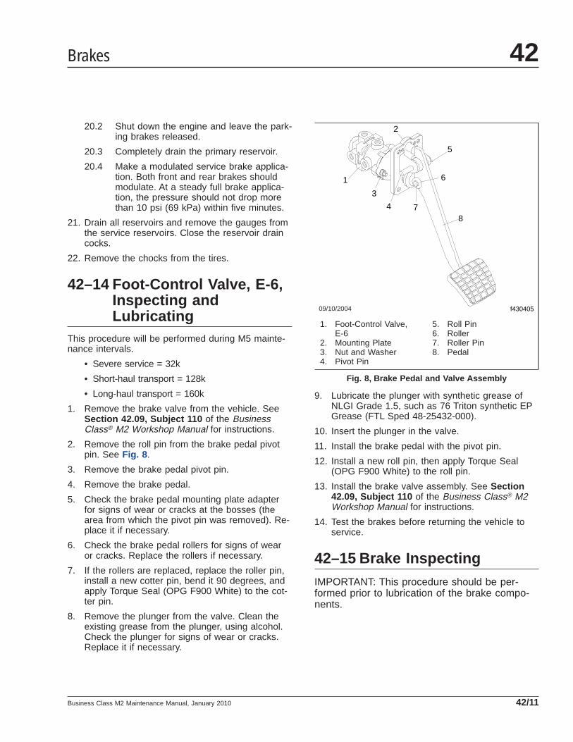
20.2 Shut down the engine and leave the park-ing brakes released.
20.3 Completely drain the primary reservoir.
20.4 Make a modulated service brake applica-tion. Both front and rear brakes shouldmodulate. At a steady full brake applica-tion, the pressure should not drop morethan 10 psi (69 kPa) within five minutes.
21. Drain all reservoirs and remove the gauges fromthe service reservoirs. Close the reservoir draincocks.
22. Remove the chocks from the tires.
42–14 Foot-Control Valve, E-6,Inspecting andLubricating
This procedure will be performed during M5 mainte-nance intervals.
• Severe service = 32k
• Short-haul transport = 128k
• Long-haul transport = 160k
1. Remove the brake valve from the vehicle. SeeSection 42.09, Subject 110 of the BusinessClass® M2 Workshop Manual for instructions.
2. Remove the roll pin from the brake pedal pivotpin. See Fig. 8 .
3. Remove the brake pedal pivot pin.
4. Remove the brake pedal.
5. Check the brake pedal mounting plate adapterfor signs of wear or cracks at the bosses (thearea from which the pivot pin was removed). Re-place it if necessary.
6. Check the brake pedal rollers for signs of wearor cracks. Replace the rollers if necessary.
7. If the rollers are replaced, replace the roller pin,install a new cotter pin, bend it 90 degrees, andapply Torque Seal (OPG F900 White) to the cot-ter pin.
8. Remove the plunger from the valve. Clean theexisting grease from the plunger, using alcohol.Check the plunger for signs of wear or cracks.Replace it if necessary.
9. Lubricate the plunger with synthetic grease ofNLGI Grade 1.5, such as 76 Triton synthetic EPGrease (FTL Sped 48-25432-000).
10. Insert the plunger in the valve.
11. Install the brake pedal with the pivot pin.
12. Install a new roll pin, then apply Torque Seal(OPG F900 White) to the roll pin.
13. Install the brake valve assembly. See Section42.09, Subject 110 of the Business Class® M2Workshop Manual for instructions.
14. Test the brakes before returning the vehicle toservice.
42–15 Brake InspectingIMPORTANT: This procedure should be per-formed prior to lubrication of the brake compo-nents.
09/10/2004 f430405
1
2
3
4
6
78
5
1. Foot-Control Valve,E-6
2. Mounting Plate3. Nut and Washer4. Pivot Pin
5. Roll Pin6. Roller7. Roller Pin8. Pedal
Fig. 8, Brake Pedal and Valve Assembly
Brakes 42
Business Class M2 Maintenance Manual, January 2010 42/11

Parking Brake Operational Check
CAUTIONPerform the following check in a clear safe area. Ifthe parking brakes fail to hold the vehicle, per-sonal injury or property damage may result.
1. With the engine running, and air pressure at cut-out pressure, set the parking brake.
2. Put the vehicle in the lowest gear and gently at-tempt to move it forward. The vehicle should notmove. If the vehicle moves, the parking brakesare not operating correctly and must be repairedbefore the vehicle is returned to service. SeeGroup 42 of the Business Class® M2 WorkshopManual for repair procedures.
Brake Component Inspection1. Park the vehicle on a level surface, set the park-
ing brake, and chock the tires. Once the tires arechocked, release the parking brake.
WARNINGManually adjusting an automatic slack adjuster tobring the pushrod stroke within legal limits islikely masking a mechanical problem. Adjustmentis not repairing. Before adjusting an automaticslack adjuster, troubleshoot the foundation brakesystem and inspect it for worn or damaged com-ponents. Improperly maintaining the vehicle brak-ing system may lead to brake failure, resulting inproperty damage, personal injury, or death.
2. With the engine off, and 100 psi (689 kPa) of airtank pressure, have an assistant apply and holdan 80 to 90 psi (550 to 620 kPa) brake applica-tion.
3. Check to see if the colored over-stroke band oneach brake chamber pushrod is exposed.
If a band shows, the stroke is too long. Checkthe foundation brake components for wear ordamage, and repair as needed. See Group 42 ofthe Business Class® M2 Workshop Manual forinspection, troubleshooting, and repair proce-dures.
4. Measure the applied chamber stroke. SeeTable 1 for the proper stroke for the type ofchamber being used. If the stroke is too short,
the brakes may drag or will not fully apply. Checkfor improper operation or adjustment of the auto-matic slack adjuster. See Group 42 of theBusiness Class® M2 Workshop Manual for in-spection and troubleshooting procedures.
5. Start the engine and build air pressure to at least100 psi (689 kPa). Shut down the engine.
6. Check all of the foundation brake components fordamage, wear, and loose or missing parts. Re-pair as needed. See Group 42 of the BusinessClass® M2 Workshop Manual for repair proce-dures.
42–16 Bendix Hydro-Max ®
Brake System Inspecting1. Check the fluid level in the hydraulic brake fluid
reservoir. If needed, fill the reservoir up to theridge that surrounds the reservoir. See Fig. 9 .Use only heavy-duty brake fluid, DOT 6.
2. Check all hydraulic lines and fittings for damage,leakage, or looseness.
Replace damaged or leaking components, andtighten loose fittings.
3. Check the brake module for leaks. If leaks arefound, repair or replace the brake module. See
10/31/94 f460513a
A
B
A. Open caps and check fluid level.B. Fill to this level.
Fig. 9, Hydraulic Brake Fluid Reservoir
Brakes42
Business Class M2 Maintenance Manual, January 201042/12
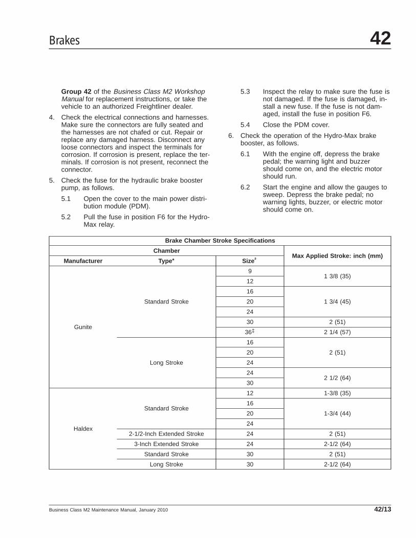
Group 42 of the Business Class M2 WorkshopManual for replacement instructions, or take thevehicle to an authorized Freightliner dealer.
4. Check the electrical connections and harnesses.Make sure the connectors are fully seated andthe harnesses are not chafed or cut. Repair orreplace any damaged harness. Disconnect anyloose connectors and inspect the terminals forcorrosion. If corrosion is present, replace the ter-minals. If corrosion is not present, reconnect theconnector.
5. Check the fuse for the hydraulic brake boosterpump, as follows.
5.1 Open the cover to the main power distri-bution module (PDM).
5.2 Pull the fuse in position F6 for the Hydro-Max relay.
5.3 Inspect the relay to make sure the fuse isnot damaged. If the fuse is damaged, in-stall a new fuse. If the fuse is not dam-aged, install the fuse in position F6.
5.4 Close the PDM cover.
6. Check the operation of the Hydro-Max brakebooster, as follows.
6.1 With the engine off, depress the brakepedal; the warning light and buzzershould come on, and the electric motorshould run.
6.2 Start the engine and allow the gauges tosweep. Depress the brake pedal; nowarning lights, buzzer, or electric motorshould come on.
Brake Chamber Stroke Specifications
ChamberMax Applied Stroke: inch (mm)
Manufacturer Type * Size†
Gunite
Standard Stroke
91 3/8 (35)
12
16
1 3/4 (45)20
24
30 2 (51)
36‡ 2 1/4 (57)
Long Stroke
16
2 (51)20
24
242 1/2 (64)
30
Haldex
Standard Stroke
12 1-3/8 (35)
16
1-3/4 (44)20
24
2-1/2-Inch Extended Stroke 24 2 (51)
3-Inch Extended Stroke 24 2-1/2 (64)
Standard Stroke 30 2 (51)
Long Stroke 30 2-1/2 (64)
Brakes 42
Business Class M2 Maintenance Manual, January 2010 42/13

Brake Chamber Stroke Specifications
ChamberMax Applied Stroke: inch (mm)
Manufacturer Type * Size†
Meritor
Standard Stroke
9Less than 1-1/2 (38)
12
16Less than 1-3/4 (44)
20
24 Less than 1-7/8 (48)
Long Stroke 24Less than 2 (51)
Standard Stroke 30* Long stroke design is indicated by a tag, or embossing, on the brake chamber.† Specifications are relative to a brake application with 80 to 90 psi (550 to 620 kPa) air pressure in the brake chambers.‡ If type 36 chamber is used, slack length should be less than 6 inches.
Table 1, Brake Chamber Stroke Specifications
Brakes42
Business Class M2 Maintenance Manual, January 201042/14

Title of Maintenance Operation (MOP) MOP Number
Drag Link Inspecting. . . . . . . . . . . . . . . . . . . . . . . . . . . . . . . . . . . . . . . . . . . . . . . . . . . . . . . . . . . . . . . . 46–01
Drag Link Lubricating . . . . . . . . . . . . . . . . . . . . . . . . . . . . . . . . . . . . . . . . . . . . . . . . . . . . . . . . . . . . . . . 46–05
Power Steering Filter Changing. . . . . . . . . . . . . . . . . . . . . . . . . . . . . . . . . . . . . . . . . . . . . . . . . . . . . . . . 46–06
Power Steering Fluid Changing. . . . . . . . . . . . . . . . . . . . . . . . . . . . . . . . . . . . . . . . . . . . . . . . . . . . . . . . 46–02
Power Steering Fluid Level Inspecting. . . . . . . . . . . . . . . . . . . . . . . . . . . . . . . . . . . . . . . . . . . . . . . . . . . 46–03
Power Steering Gear Lubricating. . . . . . . . . . . . . . . . . . . . . . . . . . . . . . . . . . . . . . . . . . . . . . . . . . . . . . . 46–04
Steering 46Index, Alphabetical
Business Class M2 Maintenance Manual, June 2002
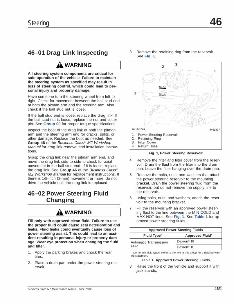
46–01 Drag Link Inspecting
WARNINGAll steering system components are critical forsafe operation of the vehicle. Failure to maintainthe steering system as specified may result inloss of steering control, which could lead to per-sonal injury and property damage.
Have someone turn the steering wheel from left toright. Check for movement between the ball stud endat both the pitman arm and the steering arm. Alsocheck if the ball stud nut is loose.
If the ball stud end is loose, replace the drag link. Ifthe ball stud nut is loose, replace the nut and cotterpin. See Group 00 for proper torque specifications.
Inspect the boot of the drag link at both the pitmanarm and the steering arm end for cracks, splits, orother damage. Replace the boot as needed. SeeGroup 46 of the Business Class® M2 WorkshopManual for drag link removal and installation instruc-tions.
Grasp the drag link near the pitman arm end, andmove the drag link side to side to check for axialmovement in the ball stud end. If it is loose, replacethe drag link. See Group 46 of the Business Class®
M2 Workshop Manual for replacement instructions. Ifthere is 1/8-inch (3-mm) movement or more, do notdrive the vehicle until the drag link is replaced.
46–02 Power Steering FluidChanging
WARNINGFill only with approved clean fluid. Failure to usethe proper fluid could cause seal deterioration andleaks. Fluid leaks could eventually cause loss ofpower steering assist. This could lead to an acci-dent resulting in personal injury or property dam-age. Wear eye protection when changing the fluidand filter.
1. Apply the parking brakes and chock the reartires.
2. Place a drain pan under the power steering res-ervoir.
3. Remove the retaining ring from the reservoir.See Fig. 1 .
4. Remove the filter and filter cover from the reser-voir. Drain the fluid from the filter into the drainpan. Leave the filter hanging over the drain pan.
5. Remove the bolts, nuts, and washers that attachthe power steering reservoir to the mountingbracket. Drain the power steering fluid from thereservoir, but do not remove the supply line tothe reservoir.
6. Using bolts, nuts, and washers, attach the reser-voir to the mounting bracket.
7. Fill the reservoir with an approved power steer-ing fluid to the line between the MIN COLD andMAX HOT lines. See Fig. 1 . See Table 1 for ap-proved power steering fluids.
Approved Power Steering Fluids
Fluid Type * Approved Fluid *
Automatic TransmissionFluid
Dexron® III
Dexron® II* Do not mix fluid types. Refer to the text in this group for a detailed warn-
ing statement.
Table 1, Approved Power Steering Fluids
8. Raise the front of the vehicle and support it withjack stands.
f461917
1
23
4
10/19/2001
1. Power Steering Reservoir2. Retaining Ring3. Filter Cover4. Return Hose
Fig. 1, Power Steering Reservoir
Steering 46
Business Class M2 Maintenance Manual, June 2002 46/1

9. Start the engine and operate it at idle. Turn thesteering wheel from full left to full right severaltimes until clean oil starts flowing from the powersteering filter. Add fluid to the reservoir to main-tain the fluid level between the MIN COLD andMAX HOT lines.
10. Shut down the engine and install the filter andfilter cover in the reservoir. Make sure that thegasket under the filter cover is not damaged. Ifthe gasket is damaged, replace it. Install the gas-ket on the reservoir.
11. Attach the retaining ring to the reservoir to se-cure the filter and filter cover.
12. Start the engine and check that the power steer-ing fluid level is between the MIN COLD andMAX HOT lines. Add more power steering fluid ifneeded.
13. Raise the vehicle, remove the jack stands, andlower the vehicle.
14. Remove the chocks from the tires.
46–03 Power Steering FluidLevel Inspecting
1. Apply the parking brakes and chock the reartires.
2. With the engine cool, the fluid level should bebetween the MIN COLD and MAX HOT lines withthe engine off.
3. Add or remove fluid as necessary to bring thefluid level to the line between the MIN COLD andMAX HOT lines. See Table 1 for approved powersteering fluids.
4. With the engine hot, the fluid level should be atthe MAX HOT line with the engine off.
5. Add or remove fluid as necessary to bring thefluid level to the MAX HOT line. See Table 1 forapproved power steering fluids.
6. Remove the chocks from the tires.
46–04 Power Steering GearLubricating
TRW THP Series
CAUTIONApply grease to the sector shaft with only a hand-type grease gun. Use of a high-pressure powergrease gun will supply grease too quickly andcould affect the high pressure seal, contaminatingthe hydraulic fluid.
Using a hand-type grease gun, apply NLGI Grade 2or 3 multipurpose chassis grease until it starts tocome out past the sector shaft seal.
46–05 Drag Link Lubricating1. Using a clean rag, wipe all dirt from both drag
link grease fittings.
2. Using a pressure gun, apply grease at thegrease fittings until old grease is forced out ofthe socket. Use multipurpose chassis greaseNLGI Grade 2 (8% 12-hydroxy lithium stearategrease) or NLGI Grade 1 (6% 12-hydroxy lithiumstearate grease).
NOTE: NLGI Grade 2 is the preferred grade.
46–06 Power Steering FilterChanging
1. Apply the parking brakes and chock the reartires.
2. Raise the front of the vehicle and support it withjack stands.
3. Remove the retaining ring from the reservoir.See Fig. 1 .
4. Remove the filter, filter cover, and gasket fromthe reservoir.
5. Disconnect the filter from the filter cover, and dis-card the filter.
6. Apply a thin film of power steering fluid on thegasket of the new filter. Then attach the filter tothe filter cover.
Steering46
Business Class M2 Maintenance Manual, June 200246/2

7. Check for damage to the gasket that was re-moved from the reservoir. If the gasket is dam-aged, replace it. Install the gasket on the reser-voir.
8. Install the filter and filter cover in the reservoir.Attach the retaining ring to the reservoir to se-cure the filter and filter cover.
9. Check the fluid level in the reservoir. If neces-sary, add fluid to the reservoir to maintain thefluid level between the MIN COLD and MAXHOT lines. See Table 1 for approved powersteering fluids.
10. Raise the vehicle and remove the jack stands,then lower the vehicle.
11. Remove the chocks from the tires.
Steering 46
Business Class M2 Maintenance Manual, June 2002 46/3

Title of Maintenance Operation (MOP) MOP Number
CNG Fuel Cylinder Inspecting. . . . . . . . . . . . . . . . . . . . . . . . . . . . . . . . . . . . . . . . . . . . . . . . . . . . . . . . . 47–07
CNG Fuel System Inspecting . . . . . . . . . . . . . . . . . . . . . . . . . . . . . . . . . . . . . . . . . . . . . . . . . . . . . . . . . 47–05
CNG High-Pressure Fuel Filter Element Replacing . . . . . . . . . . . . . . . . . . . . . . . . . . . . . . . . . . . . . . . . . 47–06
Fuel Tank Band Nut Tightening. . . . . . . . . . . . . . . . . . . . . . . . . . . . . . . . . . . . . . . . . . . . . . . . . . . . . . . . 47–01
Fuel/Water Separator Element Replacing . . . . . . . . . . . . . . . . . . . . . . . . . . . . . . . . . . . . . . . . . . . . . . . . 47–02
LNG Fuel System Inspecting . . . . . . . . . . . . . . . . . . . . . . . . . . . . . . . . . . . . . . . . . . . . . . . . . . . . . . . . . 47–03
LNG Vacuum Integrity Testing. . . . . . . . . . . . . . . . . . . . . . . . . . . . . . . . . . . . . . . . . . . . . . . . . . . . . . . . . 47–04
Fuel 47Index, Alphabetical
Business Class M2 Maintenance Manual, July 2011

47–01 Fuel Tank Band NutTightening
IMPORTANT: Do not overtighten the nuts.
Rectangular Fuel TankHold the retention nut on the fuel tank band with awrench while backing off the jam nut. Then tightenthe retention nut 13 to 17 lbf·ft (18 to 23 N·m). Afterthe retention nut has been tightened, hold the reten-tion nut with a wrench while tightening the jam nut 13to 17 lbf·ft (18 to 23 N·m).
Cylindrical Fuel TankHold the retention nut on the fuel tank band with awrench while backing off the jam nut. Then tightenthe retention nut 30 to 35 lbf·ft (41 to 46 N·m). Afterthe retention nut has been tightened, hold the reten-tion nut with a wrench while tightening the jam nut 30to 35 lbf·ft (41 to 46 N·m).
47–02 Fuel/Water SeparatorElement Replacing
AllianceThe only maintenance necessary on an Alliancefuel/water separator is to replace the filter element.
WARNINGDiesel fuel is flammable and can ignite if exposedto an open flame, intense heat, or other ignitionsource. Do not drain fuel near, or expose fuelvapor to open flame or intense heat. Exposure toopen flame or intense heat could start a fire, pos-sibly resulting in personal injury or property dam-age. When working on a fuel system, have a fireextinguisher within easy reach.
1. Drain off some fuel by loosening the vent plugand opening the drain valve. See Fig. 1 .
2. Disconnect the water sensor and heater connec-tions if equipped.
3. Remove the element and bowl together, by turn-ing counterclockwise.
4. Remove the bowl from the element and cleanthe O-ring gland.
5. Apply a coating of clean fuel or motor oil to thenew O-ring and element seal.
6. Spin the bowl onto the new element, then spinthem both onto the filter head, snugly, by handonly.
IMPORTANT: Do not use tools to tighten thebowl and element.
7. Connect the water sensor and heater connectorsif equipped.
8. If equipped with a primer pump, prime thefuel/water separator.
8.1 Loosen the vent plug. Then operate theprimer pump until the fuel purges at thevent plug.
8.2 Close the vent plug.
5
4
31
2
06/25/97 f470147
6
7
11
10
9
8
1. Mounting Head2. Fuel Primer Pump3. Vent Plug4. Bowl O-Ring5. Bowl Gasket6. Bowl Probe Plug
7. Water Sensor Probe8. Heater Connector9. Drain Plug10. Sight Bowl11. Filter Element
Fig. 1, Alliance Fuel/Water Separator
Fuel 47
Business Class M2 Maintenance Manual, July 2011 47/1

9. Start the engine and check for fuel leaks.
10. Shut down the engine and correct any fuel leaks.
Davco Fuel Pro® 232 and 233Replace the fuel/water separator element (Fig. 2 )only when the filter element is completely covered.
In the event of an emergency, when the filter needsreplacement but a Davco filter is not available, atemporary filter can be used. For instructions, seeChapter 14 of the Business Class® M2 Driver’sManual.
f47041510/16/2001
1
2
3
4
5
6
7
8
9
11
12
10
1. Filter Vent2. Vent Seal3. Filter Collar4. Filter Cover5. Cover Seal
6. Filter Spring7. Filter Element8. Temporary Filter Stud9. Fuel Outlet
10. Check Valve Fuel Inlet11. Drain12. Electric Filter Preheater
(optional)
Fig. 2, Davco Fuel Pro ® 232 and 233
Fuel47
Business Class M2 Maintenance Manual, July 201147/2

WARNINGDiesel fuel is flammable and can ignite if exposedto an open flame, intense heat, or other ignitionsource. Do not drain fuel near, or expose fuelvapor to open flame or intense heat. Exposure toopen flame or intense heat could start a fire, pos-sibly resulting in personal injury or property dam-age. When working on a fuel system, have a fireextinguisher within easy reach.
1. Drain the fuel below the collar level.
2. Using Davco wrench 232002, remove the filtercollar. Then remove the filter cover.
3. Remove the element and dispose of it properly.
4. Install a new element. Make sure the grommet isin place on the filter stud.
5. Install a new cover seal on the filter cover.
6. Using the collar, attach the filter cover with thespring to the base.
IMPORTANT: Tighten the collar by hand only.
7. Remove the filter vent. Then fill the fuel/waterseparator with fuel until the fuel level is 1 inch(2.5 cm) above the collar.
8. Install the filter vent on the fuel/water separator.
9. Start the engine and raise the rpm for oneminute to purge air.
Davco Fuel Pro® 382Replace the fuel/water separator element only whenthe filter element is completely covered.
In the event of an emergency, when the filter needsreplacement but a Davco filter is not available, atemporary filter can be used. For instructions, seeChapter 13 of the Business Class® M2 Driver’sManual.
WARNINGDiesel fuel is flammable and can ignite if exposedto an open flame, intense heat, or other ignitionsource. Do not drain fuel near, or expose fuelvapor to open flame or intense heat. Exposure toopen flame or intense heat could start a fire, pos-sibly resulting in personal injury or property dam-
age. When working on a fuel system, have a fireextinguisher within easy reach.
1. Drain the fuel below the collar level. See Fig. 3 .
2. Using Davco wrench 380134 or 382002, removethe filter collar. Then remove the filter cover.
3. Remove the element and dispose of it properly.
4. Install a new element. Make sure the grommet isin place on the filter stud.
5. Install a new cover seal on the filter cover.
6. Using the collar, attach the filter cover with thespring to the base.
IMPORTANT: Tighten the collar by hand only.
7. Remove the filter vent. Then fill the fuel/waterseparator with fuel until the fuel level is 1 inch(2.5 cm) above the collar.
8. Install the filter vent on the fuel/water separator.
9. Start the engine and raise the rpm for oneminute to purge air.
47–03 LNG Fuel SystemInspecting
WARNINGNatural gas is highly flammable. See the safetyprecautions listed in Chapter 16 of the BusinessClass ® M2 Driver’s Manual or Group 47 of theBusiness Class ® M2 Workshop Manual . Failure toobserve these precautions could lead to the igni-tion of the natural gas, which could cause seriousbodily injury or death.
The following inspections must be performed by aqualified technician, in accordance with the manufac-turer’s established inspection criteria.
All tank components should be allowed to defrostbefore conducting the following inspections.
NOTICEDo not use a high-pressure washer or steamcleaner on natural gas fuel system plumbing com-ponents, as this can introduce moisture and con-taminants into the threads of the fittings and dam-age the sealants.
Fuel 47
Business Class M2 Maintenance Manual, July 2011 47/3

Gas detection sensors are located on the caboverhead console and in the engine compartmenton the frontwall. The sensors are located in highareas, where rising gas vapors will pass by or ac-cumulate. Do not use a high-pressure washer,steam cleaner, or silicone-based chemicals on thegas detection sensors, as this may permanentlydisable the sensors. When cleaning the vehicle,cover the sensors with a plastic covering. Keepthe sensors covered until the area has beencleared of any cleaning fumes. Harsh chemicalsand extremely high temperatures may damage thesensor.
Fuel Tank and Shroud InspectingSee Fig. 4 for fuel tank and shroud componentlocations.
1. Inspect the fuel tank outer shell for dents orother signs of damage. Inspect the bottom of thetank for deep scratches, flat spots, or gouges.
Replace a leaking fuel tank.
2. Ensure that the fuel tank is secured to its mount-ing brackets and that the mounting brackets are
f470414
1
2
4
6
7
5
8
10
12
10/16/2001
9
13
11
3
1. Filter Collar2. Filter Vent3. Vent Seal4. Filter Cover5. Cover Seal6. Filter Spring
7. Filter Element8. Temporary Filter Stud9. Check Valve Fuel Inlet10. Fluid Heater/Bottom Plate and
Seal
11. Drain12. Bottom Plate Collar13. Electric Heater (optional)
Fig. 3, Davco Fuel Pro ® 382
Fuel47
Business Class M2 Maintenance Manual, July 201147/4
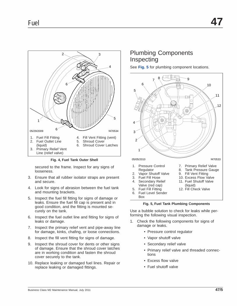
secured to the frame. Inspect for any signs oflooseness.
3. Ensure that all rubber isolator straps are presentand secure.
4. Look for signs of abrasion between the fuel tankand mounting brackets.
5. Inspect the fuel fill fitting for signs of damage orleaks. Ensure the fuel fill cap is present and ingood condition, and the fitting is mounted se-curely on the tank.
6. Inspect the fuel outlet line and fitting for signs ofleaks or damage.
7. Inspect the primary relief vent and pipe-away linefor damage, kinks, chafing, or loose connections.
8. Inspect the fill vent fitting for signs of damage.
9. Inspect the shroud cover for dents or other signsof damage. Ensure that the shroud cover latchesare in working condition and fasten the shroudcover securely to the tank.
10. Replace leaking or damaged fuel lines. Repair orreplace leaking or damaged fittings.
Plumbing ComponentsInspectingSee Fig. 5 for plumbing component locations.
Use a bubble solution to check for leaks while per-forming the following visual inspection.
1. Check the following components for signs ofdamage or leaks.
• Pressure control regulator
• Vapor shutoff valve
• Secondary relief valve
• Primary relief valve and threaded connec-tions
• Excess flow valve
• Fuel shutoff valve
05/29/2009 f470534
1
2 3
4
6
5
6
1. Fuel Fill Fitting2. Fuel Outlet Line
(liquid)3. Primary Relief Vent
Line (relief valve)
4. Fill Vent Fitting (vent)5. Shroud Cover6. Shroud Cover Latches
Fig. 4, Fuel Tank Outer Shell 05/05/2010 f470533
1
2
3
4
5
67 8
10
11
12
9
1. Pressure ControlRegulator
2. Vapor Shutoff Valve3. Fuel Fill Hose4. Secondary Relief
Valve (red cap)5. Fuel Fill Fitting6. Fuel Level Sender
Box
7. Primary Relief Valve8. Tank Pressure Gauge9. Fill Vent Fitting10. Excess Flow Valve11. Fuel Shutoff Valve
(liquid)12. Fill Check Valve
Fig. 5, Fuel Tank Plumbing Components
Fuel 47
Business Class M2 Maintenance Manual, July 2011 47/5

• Fill check valve
2. Inspect the fuel fill line for signs of damage,kinked or crushed piping, or chafing.
3. Ensure the red cap is present on the secondaryrelief valve.
4. Inspect the fuel tank pressure gauge for cracksin the sight glass. Ensure the indicator needle ispresent and in working condition. Inspect thegauge face for accuracy and legibility.
5. Inspect all vent lines for kinks, and signs of leaksor damage.
6. Replace leaking or damaged fuel lines. Repair orreplace leaking or damaged fittings.
Fuel Level Sender ComponentInspecting1. Inspect the fuel level sender wiring harness for
signs of loose connections or damage. Look forcracking or signs of moisture intrusion.
2. Inspect the fuel level sender box (Fig. 5 , Item 6)for signs of leaks or damage. Ensure that theretainer clips are installed on the mounting ears.
3. Inspect all connectors and wiring for signs ofloose connections, damage, or chafing.
4. Turn the ignition switch to the ON position andcheck for fuel gauge response.
5. Repair or replace any damaged fuel gaugecomponents.
Vaporizer InspectingSee Fig. 6 for plumbing component locations.
1. Ensure that the vaporizer is secured to itsmounting brackets and that the mountingbrackets are secured to the frame. Inspect forany signs of looseness.
2. Inspect the vaporizer fuel inlet and outlet lines forsigns of chafing, damage, or leaks.
3. Inspect the vaporizer coolant hoses for signs ofchafing, damage, or leaks.
4. Inspect all fittings for leaks.
5. Inspect the fuel shutoff solenoid valve for signsof leaks or damage. Inspect the solenoid mount-ing bracket for looseness.
6. Inspect the overpressure regulator for signs ofleaks or damage.
6.1 Ensure that the regulator is mounted se-curely.
6.2 Check the overpressure regulator fittingsfor signs of leaks or damage.
6.3 Ensure that the adjustment handle lockingnut (at the bottom of the overpressureregulator) is tightened securely.
6.4 Inspect the pressure gauge for damage.Ensure that the gauge sight glass is clearand legible.
7. Repair or replace any leaking or damaged vapor-izer components.
47–04 LNG Vacuum IntegrityTesting
WARNINGNatural gas is highly flammable. See the safetyprecautions listed in Chapter 16 of the BusinessClass ® M2 Driver’s Manual or Group 47 of theBusiness Class ® M2 Workshop Manual . Failure toobserve these precautions could lead to the igni-tion of the natural gas, which could cause seriousbodily injury or death.
1. Ensure the fuel tank is between 50 and 75 per-cent full.
2. Check the fuel tank pressure gauge (Fig. 5 , Item8) to ensure that pressure is within the normalrange of 120 to 150 psi (827 to 1034 kPa).
3. Inspect the fuel tank for signs of frost spots orouter surface sweating. Frosting or condensationon the outer surface of the fuel tank may indicatea loss of vacuum.
4. Check for a large variance in temperatures be-tween the fuel tank and the fuel tank shroud. Alarge variance in temperatures between the fueltank and the shroud may indicate a loss ofvacuum.
5. Operate the vehicle for ten minutes. Shut downthe engine, apply the parking brakes, and notethe time.
Fuel47
Business Class M2 Maintenance Manual, July 201147/6
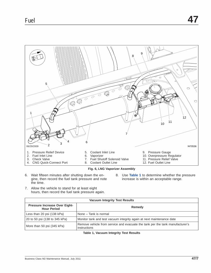
6. Wait fifteen minutes after shutting down the en-gine, then record the fuel tank pressure and notethe time.
7. Allow the vehicle to stand for at least eighthours, then record the fuel tank pressure again.
8. Use Table 1 to determine whether the pressureincrease is within an acceptable range.
Vacuum Integrity Test Results
Pressure Increase Over Eight-Hour Period Remedy
Less than 20 psi (138 kPa) None – Tank is normal
20 to 50 psi (138 to 345 kPa) Monitor tank and test vacuum integrity again at next maintenance date
More than 50 psi (345 kPa) Remove vehicle from service and evacuate the tank per the tank manufacturer’sinstructions
Table 1, Vacuum Integrity Test Results
06/29/2009 f4705362
5
6
7
89
1011
12
1
34
1. Pressure Relief Device2. Fuel Inlet Line3. Check Valve4. CNG Quick-Connect Port
5. Coolant Inlet Line6. Vaporizer7. Fuel Shutoff Solenoid Valve8. Coolant Outlet Line
9. Pressure Gauge10. Overpressure Regulator11. Pressure Relief Valve12. Fuel Outlet Line
Fig. 6, LNG Vaporizer Assembly
Fuel 47
Business Class M2 Maintenance Manual, July 2011 47/7

47–05 CNG Fuel SystemInspecting
WARNINGNatural gas is highly flammable. See the safetyprecautions listed in Chapter 16 of the BusinessClass ® M2 Driver’s Manual or Group 47 of theBusiness Class ® M2 Workshop Manual . Failure toobserve these precautions could lead to the igni-tion of the natural gas, which could cause seriousbodily injury or death.
The following inspections must be performed by aqualified technician, in accordance with the manufac-turer’s established inspection criteria.
NOTICEDo not use a high-pressure washer or steamcleaner on natural gas fuel system plumbing com-ponents, as this can introduce moisture and con-taminants into the threads of the fittings and dam-age the sealants.
Gas detection sensors are located on the caboverhead console and in the engine compartmenton the frontwall. The sensors are located in highareas, where rising gas vapors will pass by or ac-cumulate. Do not use a high-pressure washer,steam cleaner, or silicone-based chemicals on thegas detection sensors, as this may permanentlydisable the sensors. When cleaning the vehicle,cover the sensors with a plastic covering. Keepthe sensors covered until the area has beencleared of any cleaning fumes. Harsh chemicalsand extremely high temperatures may damage thesensor.
Use a bubble solution to check for leaks while per-forming the following inspection.
1. Inspect the fuel cylinders for dents or other signsof damage.
Replace any leaking fuel cylinders.
2. Ensure that the fuel cylinders are secured withinthe fuel cylinder storage box.
3. Ensure that the fuel cylinder storage box is se-cured to the frame. Inspect for any signs oflooseness. If necessary, tighten the storage boxmounting bolts 160 lbf·ft (217 N·m). See Fig. 7 .
NOTE: During initial pre-delivery inspection(PDI), tighten the storage box mounting bolts(shown in Fig. 7 ) 180 lbf·ft (244 N·m).
4. Inspect the fuel fill port for signs of damage orleaks. Ensure the port dust cover and the O-ringinside the port are both present and in good con-dition. See Fig. 8 .
5. Inspect the pressure gauges on the fuel box forcracks. Ensure the indicator needles are presentand in working condition. Inspect the gaugefaces for accuracy and legibility.
6. Ensure blue caps are present on all pressurerelief devices. Each fuel cylinder is equipped withtwo caps (one on each end), which are visible onthe back of the CNG fuel cylinder storage box.One cap is located on the pressure relief valveon the inboard side of the CNG fuel box, next to
05/04/2010 f470555
1
23 3
1. Frame Rail2. CNG Fuel Cylinder Storage Box3. Mounting Bolts (qty 12 per side)
Fig. 7, Fuel Cylinder Storage Box Mounting Bracket(passenger side shown)
Fuel47
Business Class M2 Maintenance Manual, July 201147/8
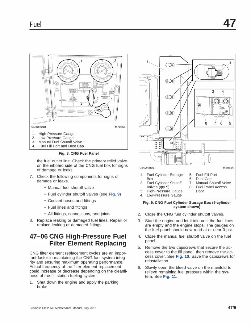
the fuel outlet line. Check the primary relief valveon the inboard side of the CNG fuel box for signsof damage or leaks.
7. Check the following components for signs ofdamage or leaks.
• Manual fuel shutoff valve
• Fuel cylinder shutoff valves (see Fig. 9 )
• Coolant hoses and fittings
• Fuel lines and fittings
• All fittings, connections, and joints
8. Replace leaking or damaged fuel lines. Repair orreplace leaking or damaged fittings.
47–06 CNG High-Pressure FuelFilter Element Replacing
CNG filter element replacement cycles are an impor-tant factor in maintaining the CNG fuel system integ-rity and ensuring maximum operating performance.Actual frequency of the filter element replacementcould increase or decrease depending on the cleanli-ness of the fill station fueling system.
1. Shut down the engine and apply the parkingbrake.
2. Close the CNG fuel cylinder shutoff valves.
3. Start the engine and let it idle until the fuel linesare empty and the engine stops. The gauges onthe fuel panel should now read at or near 0 psi.
4. Close the manual fuel shutoff valve on the fuelpanel.
5. Remove the two capscrews that secure the ac-cess cover to the fill panel, then remove the ac-cess cover. See Fig. 10 . Save the capscrews forreinstallation.
6. Slowly open the bleed valve on the manifold torelieve remaining fuel pressure within the sys-tem. See Fig. 11 .
HIGH PRESSURE PRESSURELOW
CYLINDERSINSPECT CYLINDERS
EVERY 36 MONTHSOR 36000 MILES
WHICHEVER OCCURS FIRST
NATURALGAS
VEHICLE110 PSIG
ON
MANUAL
SHUT O
FFVALV
EOPEN VALVE
SLOWLY3600 PSIG MAX.
SERVICE PRESSURE
REGULATOR
FILTER
INSPECT PRESSURERELIEF DEVICE
EVERY 2000 MILES
DRAIN HOUSINGEVERY 1500 MILESREPLACE ELEMENTEVERY 3000 MILES
1 2
34
04/30/2010 f470556
1. High Pressure Gauge2. Low Pressure Gauge3. Manual Fuel Shutoff Valve4. Fuel Fill Port and Dust Cap
Fig. 8, CNG Fuel Panel
04/22/2010 f470554
1 2
3 4
578 6
1. Fuel Cylinder StorageBox
2. Fuel Cylinder ShutoffValves (qty 5)
3. High-Pressure Gauge4. Low-Pressure Gauge
5. Fuel Fill Port6. Dust Cap7. Manual Shutoff Valve8. Fuel Panel Access
Door
Fig. 9, CNG Fuel Cylinder Storage Box (5-cylindersystem shown)
Fuel 47
Business Class M2 Maintenance Manual, July 2011 47/9
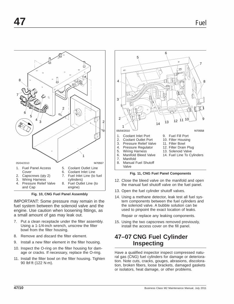
IMPORTANT: Some pressure may remain in thefuel system between the solenoid valve and theengine. Use caution when loosening fittings, asa small amount of gas may leak out.
7. Put a clean receptacle under the filter assembly.Using a 1-1/4-inch wrench, unscrew the filterbowl from the filter housing.
8. Remove and discard the filter element.
9. Install a new filter element in the filter housing.
10. Inspect the O-ring on the filter housing for dam-age or cracks. If necessary, replace the O-ring.
11. Install the filter bowl on the filter housing. Tighten90 lbf·ft (122 N·m).
12. Close the bleed valve on the manifold and openthe manual fuel shutoff valve on the fuel panel.
13. Open the fuel cylinder shutoff valves.
14. Using a methane detector, leak test all fuel sys-tem components between the fuel cylinders andthe solenoid valve. A bubble solution can beused to pinpoint the exact location of leaks.
Repair or replace any leaking components.
15. Using the two capscrews removed previously,install the access cover on the fill panel.
47–07 CNG Fuel CylinderInspecting
Have a qualified inspector inspect compressed natu-ral gas (CNG) fuel cylinders for damage or deteriora-tion. Note cuts, cracks, gouges, abrasions, discolora-tion, broken fibers, loose brackets, damaged gasketsor isolators, heat damage, or other problems.
05/04/2010 f470557
2
2
34
56
7
8
1
1. Fuel Panel AccessCover
2. Capscrews (qty 2)3. Wiring Harness4. Pressure Relief Valve
and Cap
5. Coolant Outlet Line6. Coolant Inlet Line7. Fuel Inlet Line (to fuel
cylinders)8. Fuel Outlet Line (to
engine)
Fig. 10, CNG Fuel Panel Assembly
05/04/2010 f470558
6
7
8
910111213141
2
3
4
5
1. Coolant Inlet Port2. Coolant Outlet Port3. Pressure Relief Valve4. Pressure Regulator5. Wiring Harness6. Manifold Bleed Valve7. Manifold8. Manual Fuel Shutoff
Valve
9. Fuel Fill Port10. Filter Housing11. Filter Bowl12. Filter Drain Plug13. Solenoid Valve14. Fuel Line To Cylinders
Fig. 11, CNG Fuel Panel Components
Fuel47
Business Class M2 Maintenance Manual, July 201147/10

Refer to Compressed Gas Assocation (CGA) pam-phlet C-6.4, Methods for External Visual Inspection ofNatural Gas Fuel Containers and Their Installations,for inspection requirements and inspector qualifica-tions.
For more information, go to www.cganet.com .
After inspection, an accurate and reliable written re-port should be provided for each container inspected.Place an inspection label stating the inspection dateand inspecting agency identification on each con-tainer.
Fuel 47
Business Class M2 Maintenance Manual, July 2011 47/11
Title of Maintenance Operation (MOP) MOP Number
CAT CGI Bellows Replacement. . . . . . . . . . . . . . . . . . . . . . . . . . . . . . . . . . . . . . . . . . . . . . . . . . . . . . . . 49–03
CAT CGI Bellows and Piping Inspection . . . . . . . . . . . . . . . . . . . . . . . . . . . . . . . . . . . . . . . . . . . . . . . . . 49–02
Exhaust System Inspecting (Noise Emission Control). . . . . . . . . . . . . . . . . . . . . . . . . . . . . . . . . . . . . . . . 49–01
Exhaust 49Index, Alphabetical
Business Class M2 Maintenance Manual, September 2011

49–01 Exhaust SystemInspecting (NoiseEmission Control)
In addition to inspecting the exhaust system at thescheduled maintenance interval, inspect the exhaustsystem if the noise level of the vehicle has in-creased. Freightliner Trucks recommends replacingparts that show leakage, wear, or damage, withgenuine Freightliner parts.
The exhaust system must be free of leaks, binding,grounding, and excessive vibrations. These condi-tions are usually caused by loose, broken, or mis-aligned clamps, brackets, or pipes. If any of theseconditions exist, check the exhaust system compo-nents and alignment. Align or replace as necessary;see Group 49 of the Business Class® M2 WorkshopManual, or take the vehicle to an authorized Freight-liner dealer.
It is a violation of US federal law to alter exhaustplumbing or aftertreatment in any way that wouldbring the engine out of compliance with certificationrequirements. (Ref: 42 U.S.C. S7522(a) (3).) It is theowner’s responsibility to maintain the vehicle so thatit conforms to EPA regulations.
EPA10 Exhaust SystemDefinitions of Aftertreatment (ATS)TermsRefer to the following list of definitions of ATS termsand components.
• Aftertreatment System (ATS)—the entire ex-haust system from the turbocharger to the ex-haust stack or tail pipe.
• Aftertreatment Device (ATD)—a housing thatcontains the DOC and DPF (also the SCR andthe mixing tube in one-box systems).
• BlueTec®—Daimler’s proprietary SCR technol-ogy.
• Diesel Oxidation Catalyst (DOC)—a flow-through device that oxidizes soot in the ATD.
• Diesel Particulate Filter (DPF)—a component inthe ATD that traps soot from the exhaust gas.
• Diesel Exhaust Fluid (DEF)—the chemical agentthat reacts with the exhaust gases in the SCRto reduce NOx.
• DEF Pump—filters and supplies DEF to theDEF metering unit.
• DEF Tank—holds DEF and regulates its tem-perature.
• DEF Metering Unit—mixes DEF with com-pressed air, and meters this mixture into theexhaust flow via an injection nozzle.
• SCR Catalyst—the housing containing a treatedceramic flow-through block where the DEF andexhaust gases undergo selective catalytic re-duction (SCR).
• Selective Catalytic Reduction (SCR)—a processused to reduce NOx emissions.
InspectionTo meet EPA10 emissions regulations for vehiclesdomiciled in the USA or Canada, engines manufac-tured after December 31, 2009 are equipped with anemission aftertreatment system. Vehicles domiciledoutside of the USA and Canada may not have after-treatment equipment, depending upon local statutoryemissions guidelines.
IMPORTANT: The aftertreatment device (ATD),which is part of the aftertreatment system (ATS),requires special attention during regularlyscheduled maintenance inspections. No leaksare allowed anywhere in the system. If any dis-crepancies are discovered, refer to the enginemanufacturer’s service literature for repair in-structions.
1. Check for leakage at the clamp that attaches theexhaust pipe to the turbocharger exhaust outlet.If leakage exists, tighten the nut on the clamp tothe required torque. If leakage persists, install anew clamp.
2. Check the exhaust pipe, bellows, and each ex-haust seal clamp for leakage, wear, cracks, ordamage. Replace damaged components asneeded. If leakage exists at a clamp, tighten thenuts to the required torque. If leakage persists,install a new exhaust seal clamp. Do not reuseseal clamps. Once a seal clamp is loosened orremoved, it must be replaced.
Exhaust 49
Business Class M2 Maintenance Manual, September 2011 49/1

3. If present, check the condition of the insulationmaterial around the exhaust pipe between theturbocharger and the ATD.
4. Check the ATD mounting bands for tightness.Tighten to 30 lbf·ft (41 N·m) if needed. Do notovertighten.
5. Check for leaks around the clamps that attachthe ATD in the ATS, and around the clamps thatretain the DPF in the ATD.
6. Check all sensors attached to the ATS for leaksor damaged wires. No leaks are allowed. SeeFig. 1 , Fig. 2 , or Fig. 3 for Detroit Diesel ATSsensor locations.
7. Check the DPF exterior surface for dents orother damage. A dent over 3 inches (76 mm) indiameter and 1/4-inch (6-mm) deep could causeinternal damage to the DPF, causing it tomalfunction.
8. Check the SCR catalyst for dents and otherdamage.
9. Check for heat discoloration on the surface ofthe ATD. Heat discoloration may indicate internaldamage; especially around the DPF.
NOTE: Diesel exhaust fluid creeps, causingwhite crystals to form around the line fittings.The presence of crystals does not mean thesystem has a leak. Replacing fittings or trouble-shooting components is not necessary unlessthere is a system failure or a fault code.
10. Check the DEF tank, pump, metering unit, andlines for leaks. See Section 49.03 of theBusiness Class® M2 Workshop Manual for repairprocedures.
08/20/2009 f490355
12
3
4
5
6
7
8
9
1011
121314
9
15
NOTE: The sensor box (item 8) contains the SCR inlet and outlet NOx sensors, DPF outlet pressure sensor, and theDOC inlet pressure sensor.
1. DOC Outlet TemperatureSensor
2. DOC Inlet Pressure SensorPort
3. DOC Inlet Temperature Sensor4. Front Heat Shield5. DEF Nozzle
6. Exhaust Outlet7. DEF Metering Unit8. Sensor Box (see note above)9. Exhaust Inlet10. SCR Outlet Temperature
Sensor
11. SCR Outlet NOx Sensor Port12. SCR Inlet NOx Sensor Port13. 14-Pin Connectors14. DPF Outlet Pressure Sensor
Port15. SCR Inlet Temperature Sensor
Fig. 1, One-Box ATS Sensor Locations
Exhaust49
Business Class M2 Maintenance Manual, September 201149/2

11. Check any wires, lines, or hoses within 4 inches(10 cm) of the exhaust system for heat damage.Repair or reroute as needed.
Diesel Exhaust Fluid (DEF) FilterReplacementThe Environmental Protection Agency’s 2010 regula-tions require lower nitrogen oxide (NOx) exhaustemissions. Selective catalytic reduction (SCR) usesdiesel exhaust fluid (DEF) to lower NOx emissions inthe vehicle exhaust. A filter in the DEF pump pre-vents clogging of the DEF metering unit injectionnozzle.
See the engine manufacturer’s maintenance manualfor filter replacement instructions and maintenanceintervals.
EPA07 Exhaust SystemDefinitions of ATS TermsRefer to the following list of definitions of ATS com-ponents.
• Aftertreatment System (ATS)—the entire ex-haust system from the turbocharger to the ex-haust stack or tail pipe.
09/16/2009
12
3
4
5
6
7
89
1011
f490353
10
98
1. DEF Metering Unit2. DEF Nozzle3. SCR Outlet Temperature
Sensor4. SCR Inlet Temperature Sensor
5. DOC Inlet Temperature Sensor6. DOC Inlet Pressure Sensor7. DPF Inlet Temperature Sensor8. DPF Outlet Pressure Sensor
9. DPF Outlet TemperatureSensor
10. DPF Outlet NOx Sensor11. SCR Outlet NOx Sensor
Fig. 2, 2V2 Two-Box ATS Sensor Locations
Exhaust 49
Business Class M2 Maintenance Manual, September 2011 49/3
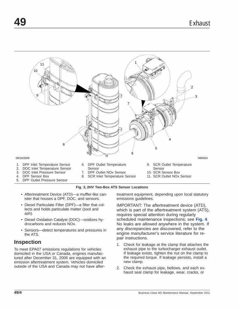
• Aftertreatment Device (ATD)—a muffler-like can-ister that houses a DPF, DOC, and sensors.
• Diesel Particulate Filter (DPF)—a filter that col-lects and holds particulate matter (soot andash).
• Diesel Oxidation Catalyst (DOC)—oxidizes hy-drocarbons and reduces NOx.
• Sensors—detect temperatures and pressures inthe ATS.
InspectionTo meet EPA07 emissions regulations for vehiclesdomiciled in the USA or Canada, engines manufac-tured after December 31, 2006 are equipped with anemission aftertreatment system. Vehicles domiciledoutside of the USA and Canada may not have after-
treatment equipment, depending upon local statutoryemissions guidelines.
IMPORTANT: The aftertreatment device (ATD),which is part of the aftertreatment system (ATS),requires special attention during regularlyscheduled maintenance inspections; see Fig. 4 .No leaks are allowed anywhere in the system. Ifany discrepancies are discovered, refer to theengine manufacturer’s service literature for re-pair instructions.
1. Check for leakage at the clamp that attaches theexhaust pipe to the turbocharger exhaust outlet.If leakage exists, tighten the nut on the clamp tothe required torque. If leakage persists, install anew clamp.
2. Check the exhaust pipe, bellows, and each ex-haust seal clamp for leakage, wear, cracks, or
09/16/2009 f490354
1
2
3
4
56
7
8
9
10
11
1. DPF Inlet Temperature Sensor2. DOC Inlet Temperature Sensor3. DOC Inlet Pressure Sensor4. DPF Sensor Box5. DPF Outlet Pressure Sensor
6. DPF Outlet TemperatureSensor
7. DPF Outlet NOx Sensor8. SCR Inlet Temperature Sensor
9. SCR Outlet TemperatureSensor
10. SCR Sensor Box11. SCR Outlet NOx Sensor
Fig. 3, 2HV Two-Box ATS Sensor Locations
Exhaust49
Business Class M2 Maintenance Manual, September 201149/4
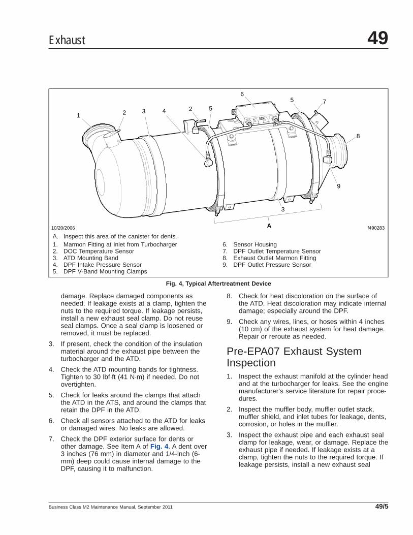
damage. Replace damaged components asneeded. If leakage exists at a clamp, tighten thenuts to the required torque. If leakage persists,install a new exhaust seal clamp. Do not reuseseal clamps. Once a seal clamp is loosened orremoved, it must be replaced.
3. If present, check the condition of the insulationmaterial around the exhaust pipe between theturbocharger and the ATD.
4. Check the ATD mounting bands for tightness.Tighten to 30 lbf·ft (41 N·m) if needed. Do notovertighten.
5. Check for leaks around the clamps that attachthe ATD in the ATS, and around the clamps thatretain the DPF in the ATD.
6. Check all sensors attached to the ATD for leaksor damaged wires. No leaks are allowed.
7. Check the DPF exterior surface for dents orother damage. See Item A of Fig. 4 . A dent over3 inches (76 mm) in diameter and 1/4-inch (6-mm) deep could cause internal damage to theDPF, causing it to malfunction.
8. Check for heat discoloration on the surface ofthe ATD. Heat discoloration may indicate internaldamage; especially around the DPF.
9. Check any wires, lines, or hoses within 4 inches(10 cm) of the exhaust system for heat damage.Repair or reroute as needed.
Pre-EPA07 Exhaust SystemInspection1. Inspect the exhaust manifold at the cylinder head
and at the turbocharger for leaks. See the enginemanufacturer’s service literature for repair proce-dures.
2. Inspect the muffler body, muffler outlet stack,muffler shield, and inlet tubes for leakage, dents,corrosion, or holes in the muffler.
3. Inspect the exhaust pipe and each exhaust sealclamp for leakage, wear, or damage. Replace theexhaust pipe if needed. If leakage exists at aclamp, tighten the nuts to the required torque. Ifleakage persists, install a new exhaust seal
f490283
1 22 5
65 7
8
9
3
3
4
10/20/2006 A
A. Inspect this area of the canister for dents.1. Marmon Fitting at Inlet from Turbocharger2. DOC Temperature Sensor3. ATD Mounting Band4. DPF Intake Pressure Sensor5. DPF V-Band Mounting Clamps
6. Sensor Housing7. DPF Outlet Temperature Sensor8. Exhaust Outlet Marmon Fitting9. DPF Outlet Pressure Sensor
Fig. 4, Typical Aftertreatment Device
Exhaust 49
Business Class M2 Maintenance Manual, September 2011 49/5

clamp. Do not reuse seal clamps. Once a sealclamp is loosened or removed, it must be re-placed.
4. Check for leakage at the clamp that attaches theexhaust pipe to the turbocharger exhaust outlet.If leakage exists, tighten the nut on the clamp tothe required torque. If leakage persists, install anew clamp.
49–02 CAT CGI Bellows andPiping Inspection
On vehicles with CAT engines,
NOTICEA leak in the CGI piping, including the bellows,will allow unfiltered air and contaminants into theengine intake, and can cause serious engine dam-age.
NOTE: Because the CGI bellows is coveredwith a metal mesh, it is difficult to see cracks ordamage that may cause a leak.
1. Inspect the CGI bellows and piping for evidenceof damage or leakage. See Fig. 5 . If the bellowsis damaged or leaking, replace it. See 49–03 forthe replacement procedure.
2. Check the CGI piping and each exhaust sealclamp for leakage, wear, cracks, or damage. Re-place damaged components as needed. If leak-age exists at a clamp, tighten the nuts to the re-quired torque. If leakage persists, install a newexhaust seal clamp. Do not reuse seal clamps.Once a seal clamp is loosened or removed, itmust be replaced. If any of the components isdamaged or leaking, replace it. See 49–03 forthe replacement procedure.
49–03 CAT CGI BellowsReplacement
On vehicles with CAT EPA07 compliant engines, re-place the CGI bellows at the M3 maintenance inter-val to prevent a later failure.
NOTICEA leak in the CGI piping, including the bellows,will allow unfiltered air and contaminants into theengine intake, and can cause serious enginedamage.
1. Park the vehicle, set the parking brake, chockthe wheels.
2. Open the hood.
02/24/2011 f490456
1
12 3 4 5 6 5 3 7 8 9 3 10
1. Clamp2. Inlet Pipe3. U-Clamp4. Forward Pipe-Support Brace
5. Slip Clamp6. CGI Bellows7. Center Pipe-Support Brace
8. Center Pipe9. Clamp10. Outlet Pipe
Fig. 5, CAT EPA07 Exhaust Installation with CGI Bellows
Exhaust49
Business Class M2 Maintenance Manual, September 201149/6

3. Remove the right side inner fender/splash shieldas needed.
4. Remove the CGI piping between the engine andaftertreatment device (ATD).
See Fig. 6 .
5. On the workbench, remove the CGI bellows fromthe exhaust piping. Do not damage the piping.
NOTE: The following step, and its substeps, isto be done without the bellows installed. Thiswill align the pipes so that the bellows can beinstalled correctly.
6. Install the CGI piping (without CGI bellows) andalign piping.
6.1 Attach the aft CGI pipe to the ATD.
6.2 Attach the forward CGI pipe to the en-gine.
NOTICEWhen the CGI pipes and bellows are installed,there should be approximately 3/4 inch (19 mm)clearance from the main bellows. Contact betweenthe bellows could result in an exhaust leak, whichin this case may allow ingestion of contaminantsinto the engine causing engine damage.
6.3 Use a straightedge to align the pipes sothat the pipe ends that attach to the bel-lows are parallel and concentric.
NOTICEWhen shortening the CGI pipe(s), it is critical toleave a minimum of 1 inch (25.4 mm) of straightpipe on the end of each CGI pipe to allow for pipeinsertion and clamp clearance. Failure to do thiscould result in an exhaust leak, which in this casemay allow ingestion of contaminants into the en-gine causing engine damage.
7. Once the pipes are aligned, measure the pipegap between the CGI pipes and record the dis-tance. See Fig. 7 , Ref. A.
The existing pipe gap is designed at 10 inches(254 mm). A 10.75 inches (273 mm) pipe gap isrequired for the replacement CGI bellows andclamps. This requires one or both of the CGIpipes to be shortened.
8. Using a yellow paint pen, mark the pipes 1.5inches (38 mm) in from the end of each pipe.These two marks will be used to center the bel-lows between the two pipes.
9. Once the pipes are correctly aligned and sepa-rated at the correct distance, secure the aft CGIpipe to the ATD and to any CGI pipe supportbrackets.
10. Remove the forward CGI pipe from the truck.
11. Slide the slip clamp, with the retaining ring andgraphite gasket ring, on the aft CGI pipe. SeeFig. 8 for proper installation.
12. Slide the new bellows onto the aft CGI pipe asfar as it will go. See Fig. 9 , Ref. A. MeasurementA should be at least 7/16 inch (10 mm) past theface of the flange.
13. Install the slip clamp with the retaining ring andgraphite gasket ring onto the forward CGI pipe.See Fig. 10 for proper installation.
14. Slide the end of the forward CGI pipe into thebellows, and properly align the pipe.
15. Secure the forward CGI pipe to the engine andany CGI pipe support brackets.
16. Using the yellow marks, center the bellows be-tween the exhaust pipes. Verify that the pipe isinserted at least 7/16 inch (10 mm) past the faceof the flange. See Fig. 9 , Ref. A.
17. Install the slip clamps on the bellows. Tighten theslip clamps 11 lbf·ft (15 N·m).
18. Start the engine and check for exhaust leaks.Tighten any clamps as needed.
Exhaust 49
Business Class M2 Maintenance Manual, September 2011 49/7

02/24/2011 f490456
1
12 3 4 5 6 5 3 7 8 9 3 10
1. Clamp2. Inlet Pipe3. U-Clamp4. Forward Pipe-Support Brace
5. Slip Clamp6. CGI Bellows7. Center Pipe-Support Brace
8. Center Pipe9. Clamp10. Outlet Pipe
Fig. 6, CAT EPA07 Exhaust Installation with CGI Bellows
02/23/2011 f490457
12
A
A. Measure the pipe gap.1. CGI Aft Pipe 2. CGI Forward Pipe
Fig. 7, Measuring the Pipe Gap (typical)
01/29/2010
1 2 3 4 5
f490415
1. Aft CGI Pipe2. Retaining Ring3. Graphite Gasket
4. Slip Clamp5. CGI Bellows
Fig. 8, Aft Facing Slip Clamp Installation
Exhaust49
Business Class M2 Maintenance Manual, September 201149/8

02/23/2011 f490458
A A21 3
A. At least 7/16 inch (10 mm)1. Forward CGI Pipe2. CGI Bellows
3. Aft CGI Pipe
Fig. 9, CGI Bellows Installation
02/08/2010 f490417
54321
1. CGI Bellows2. Slip Clamp3. Retaining Ring
4. Graphite Gasket5. Forward CGI Pipe
Fig. 10, Forward Facing Slip Clamp Installation
Exhaust 49
Business Class M2 Maintenance Manual, September 2011 49/9

Title of Maintenance Operation (MOP) MOP Number
Mirror Folding Check . . . . . . . . . . . . . . . . . . . . . . . . . . . . . . . . . . . . . . . . . . . . . . . . . . . . . . . . . . . . . . . 60–01
Cab 60Index, Alphabetical
Business Class M2 Maintenance Manual, July 2010

60–01 Mirror Folding CheckFor vehicles with folding main mirrors, make surethat the mirrors fold freely on the pivot points. Pivoteach mirror fully forward and backward two times tobreak loose any debris that may affect the fold-awayfeature of the mirror.
Cab 60
Business Class M2 Maintenance Manual, July 2010 60/1

Title of Maintenance Operation (MOP) MOP Number
Door Seals Lubricating. . . . . . . . . . . . . . . . . . . . . . . . . . . . . . . . . . . . . . . . . . . . . . . . . . . . . . . . . . . . . . 72–01
Doors 72Index, Alphabetical
Business Class M2 Maintenance Manual, June 2002

72–01 Door Seals LubricatingNOTE: Only the door seals require lubrication.Do not lubricate the door latches or hinges.They come from the manufacturer with lifetimelubrication and require no maintenance.
Lightly coat the door seals with a lubricant that issafe for rubber.
Doors 72
Business Class M2 Maintenance Manual, June 2002 72/1

Title of Maintenance Operation (MOP) MOP Number
Air Conditioner Inspecting. . . . . . . . . . . . . . . . . . . . . . . . . . . . . . . . . . . . . . . . . . . . . . . . . . . . . . . . . . . . 83–01
HVAC Air Filter Replacing. . . . . . . . . . . . . . . . . . . . . . . . . . . . . . . . . . . . . . . . . . . . . . . . . . . . . . . . . . . . 83–02
Heater and Air Conditioner 83Index, Alphabetical
Business Class M2 Maintenance Manual, December 2001

83–01 Air ConditionerInspecting
Refrigerant CompressorInspection1. With the vehicle parked on a level surface, apply
the parking brakes and chock the tires.
2. Operate the heater and, if equipped with an airconditioner, the air conditioner to check forproper operation in all modes.
3. Open the hood.
4. Check the condition of the refrigerant compres-sor clutch assembly. If the friction surface of thepulley shows signs of excessive grooving due tobelt slippage, replace both the pulley and thedrive plate.
5. Inspect the refrigerant compressor drive belt fordamage. If needed, replace the drive belt.
6. Check the tightness of the compressor mountingfasteners. The torque value for the mounting fas-teners is 15 to 19 lbf·ft (20 to 26 N·m).
7. Inspect the drive plate. If the friction surface ofthe drive plate shows visible signs of damagedue to excessive heat, make sure the refrigerantcompressor turns freely. If the compressor doesturn freely, replace the drive plate and clutch as-sembly. For instructions, see Section 83.01 ,Subject 140 of the Business Class® M2 Work-shop Manual. If the compressor does not turnfreely, replace the compressor. For instructions,see Section 83.01 , Subject 120 of the BusinessClass® M2 Workshop Manual
8. Use a feeler gauge to check that the drive plateclutch clearance is 0.016 to 0.031 inch (0.4 to0.8 mm). If the gap is not even around theclutch, gently tap down at the high areas. If theoverall gap is out of spec, remove the drive plateassembly and change the shims as necessary.For instructions, see Section 83.01 , Subject 140of the Business Class® M2 Workshop Manual.
9. Check that the wiring harness connector is notdamaged or loose. Replace the wiring harness ifit is damaged.
10. Check the overall condition of the air conditioninghoses. Look for cracks, cuts, and abrasions onthe hoses. Replace damaged hoses.
11. Check for a buildup of road debris on the con-denser fins. Using air pressure and a whiskbroom or a soapy spray of water, carefully cleanoff the condenser. Be careful not to bend thefins.
12. Check the moisture indicator on the receiver-drier. See Fig. 1 . If the indicator is a deep cobaltblue, the refrigerant charge is dry. If the indicatoris not blue, the system is contaminated withwater. If the system is contaminated, recover therefrigerant, replace the receiver drier, evacuatethe system, and add a full refrigerant charge. Forinstructions, see Section 83.00 , Subject 220 ofthe Business Class® M2 Workshop Manual.
13. Close the hood and remove the chocks from thetires.
83–02 HVAC Air FilterReplacing
The HVAC air filter must be replaced every sixmonths or 60,000 miles (97 000 km) to permit properoperation of the HVAC system.
1. With the vehicle parked, apply the parkingbrakes, and chock the tires.
12/21/2001 f543878
1 2 3
4
1. Fan Cycling Switch2. Moisture Indicator
3. Binary Switch4. Receiver-Drier
Fig. 1, Receiver-Drier
Heater and Air Conditioner 83
Business Class M2 Maintenance Manual, December 2001 83/1

2. Remove the lower HVAC cover in the cab. Forinstructions, see Group 60 of the BusinessClass® M2 Workshop Manual.
3. Disconnect the wiring harness from the evapora-tor probe.
4. Remove the capscrews that attach the evapora-tor service cover to the HVAC assembly. Removethe evaporator service cover.
5. Pull the filter out of the HVAC assembly.
6. Install a new filter in the HVAC assembly. Besure that the arrow on the filter is pointing towardthe evaporator. See Fig. 2 .
7. Remove the condensate seal from the evapora-tor service cover and install a new condensateseal on the cover.
8. Using capscrews, attach the evaporator servicecover to the HVAC assembly.
9. Connect the wiring harness to the evaporatorprobe.
10. Attach the lower HVAC cover to the dash panel.For instructions, see Group 60 of the BusinessClass® M2 Workshop Manual.
11. Remove the chocks from the tires.
10/04/2001 f543921
21
1. Evaporator 2. Filter
Fig. 2, HVAC Assembly Filter
Heater and Air Conditioner83
Business Class M2 Maintenance Manual, December 200183/2

Title of Maintenance Operation (MOP) MOP Number
Hood Rear Support Lubrication. . . . . . . . . . . . . . . . . . . . . . . . . . . . . . . . . . . . . . . . . . . . . . . . . . . . . . . . 88–01
Hood, Grille, and Cab Fenders 88Index, Alphabetical
Business Class M2 Maintenance Manual, July 2010
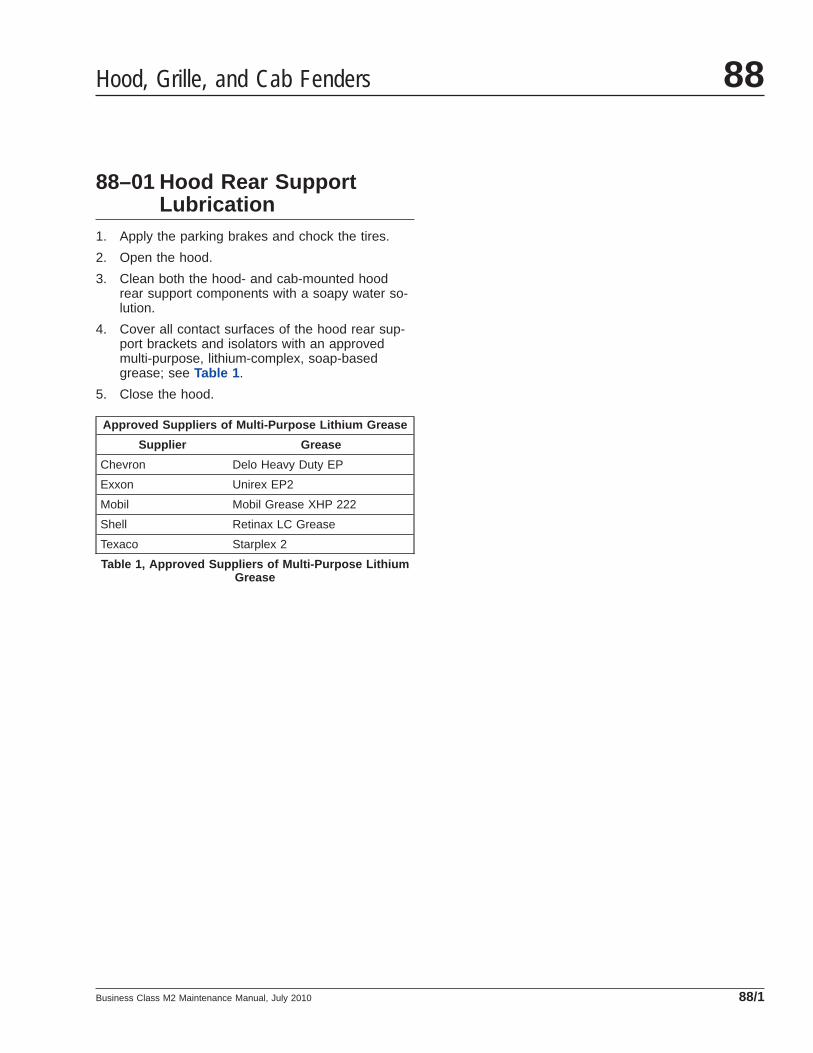
88–01 Hood Rear SupportLubrication
1. Apply the parking brakes and chock the tires.
2. Open the hood.
3. Clean both the hood- and cab-mounted hoodrear support components with a soapy water so-lution.
4. Cover all contact surfaces of the hood rear sup-port brackets and isolators with an approvedmulti-purpose, lithium-complex, soap-basedgrease; see Table 1 .
5. Close the hood.
Approved Suppliers of Multi-Purpose Lithium Grease
Supplier Grease
Chevron Delo Heavy Duty EP
Exxon Unirex EP2
Mobil Mobil Grease XHP 222
Shell Retinax LC Grease
Texaco Starplex 2
Table 1, Approved Suppliers of Multi-Purpose LithiumGrease
Hood, Grille, and Cab Fenders 88
Business Class M2 Maintenance Manual, July 2010 88/1


