BUS SUPPORTS - hubbellcdn.com · SD 3 SD1CATLD OG NUUCMMBGELRCAGTIT(C)TG .SAHL...
24
ANDERSON ™ HUBBELL ® POWER SYSTEMS FARGO ® January 2015 BUS SUPPORTS BOLTED/ALUMINUM ACS. .......................... CABLE.TO.INSULATOR..................................................................................................... SD-1 ADCS....................... TWO.CABLE.OR.TUBES.TO.INSULATOR...............................................................SD-3 ASR. .......................... CABLE.OR.TUBE.TO.INSULATOR..............................................................................SD-2 ATSF. ........................ TUBE.TO.INSULATOR....................................................................................................... SD-5 AUDE. ...................... VERTICAL,.TUBE.TO.INSULATOR..............................................................................SD-7 AUR.......................... TUBE.TO.INSULATOR...................................................................................................... SD-4 AURC. ...................... TUBE.TO.INSULATOR.(COUPLER). ........................................................................... SD-6 AURF....................... EXPANSION,.TUBE.TO.INSULATOR......................................................................... SD-8 BOLTED/BRONZE BHX.......................... FLAT.BAR.TO.INSULATOR........................................................................................... SD-15 BVX. .......................... VERTICAL.RIGID,.FLAT.BAR.TO.INSULATOR. .................................................... SD-17 BVXA....................... VERTICAL.SLIP.TYPE,.FLAT.BAR.TO.INSULATOR.......................................... SD-16 CDSB....................... TWO.CABLES.OR.TUBES.TO.INSULATOR.......................................................... SD-12 CSSB........................ CABLE.OR.TUBE.TO.INSULATOR............................................................................. SD-11 ICA............................ CABLE.OR.TUBE.TO.INSULATOR............................................................................SD-10 UDE.......................... VERTICAL,.TUBE.TO.INSULATOR............................................................................ SD-14 UP. ............................. TUBE.TO.INSULATOR..................................................................................................... SD-13 WELDMENT/ALUMINUM WTH. ........................ TUBE.TO.INSULATOR................................................................................................... SD-20 WUDE..................... TUBE.TO.INSULATOR.................................................................................................... SD-23 WURE. ..................... TUBE.TO.INSULATOR..................................................................................................... SD-19 WURF. ..................... EXPANSION,.TUBE.TO.INSULATOR....................................................................... SD-22
Transcript of BUS SUPPORTS - hubbellcdn.com · SD 3 SD1CATLD OG NUUCMMBGELRCAGTIT(C)TG .SAHL...
ANDERSON™ HUBBELL®POWERSYSTEMS FARGO® January2015
BUS SUPPORTS
BOLTED/ALUMINUMACS...........................CABLE.TO.INSULATOR......................................................................................................SD-1ADCS........................TWO.CABLE.OR.TUBES.TO.INSULATOR................................................................SD-3ASR...........................CABLE.OR.TUBE.TO.INSULATOR...............................................................................SD-2ATSF.........................TUBE.TO.INSULATOR........................................................................................................SD-5AUDE.......................VERTICAL,.TUBE.TO.INSULATOR...............................................................................SD-7AUR...........................TUBE.TO.INSULATOR.......................................................................................................SD-4AURC.......................TUBE.TO.INSULATOR.(COUPLER)............................................................................ SD-6AURF........................EXPANSION,.TUBE.TO.INSULATOR.......................................................................... SD-8
BOLTED/BRONZEBHX...........................FLAT.BAR.TO.INSULATOR............................................................................................SD-15BVX...........................VERTICAL.RIGID,.FLAT.BAR.TO.INSULATOR.....................................................SD-17BVXA........................VERTICAL.SLIP.TYPE,.FLAT.BAR.TO.INSULATOR...........................................SD-16CDSB........................TWO.CABLES.OR.TUBES.TO.INSULATOR...........................................................SD-12CSSB.........................CABLE.OR.TUBE.TO.INSULATOR.............................................................................. SD-11ICA.............................CABLE.OR.TUBE.TO.INSULATOR.............................................................................SD-10UDE...........................VERTICAL,.TUBE.TO.INSULATOR.............................................................................SD-14UP..............................TUBE.TO.INSULATOR......................................................................................................SD-13
WELDMENT/ALUMINUMWTH.........................TUBE.TO.INSULATOR.................................................................................................... SD-20WUDE......................TUBE.TO.INSULATOR.....................................................................................................SD-23WURE......................TUBE.TO.INSULATOR......................................................................................................SD-19WURF......................EXPANSION,.TUBE.TO.INSULATOR........................................................................SD-22

SD1
ANDERSON™ HUBBELL®POWERSYSTEMS FARGO® January2015
CATALOG NUMBER
CABLE RANGE CABLE DIAMETER (MM) BOLTCIRCLE
DIA.
DIMENSIONS INCHES (MM) APPROX. WT. EACH LBS. (KG)AAC ACSR
SMALL GROOVE
LARGE GROOVE L C W
ACS63 #4-250 MCM #4-4/0.232-.500
(5.9)-(12.7)
.500-.575
(12.5)-(14.6)
33
(76.2)
2-5/8
(69.9)
2-7/16
(61.9)
1.9
(.86)
ACS65 #4-250 MCM #4-4/0 53
(76.2)
2-5/8
(69.9)
2-7/16
(61.9)
2.8
(1.27)
ACS93 4/0-600 MCM 4/0-477.522-.656
(13.3)-(16.7)
.656-.893
(16.7)-(22.7)
33-1/4
(82.6)
2-3/4
(69.9)
2-11/16
(68.2)
2.2
(1.0)
ACS95 4/0-600 MCM 4/0-477 53-1/2
(88.9)
2-3/4
(69.9)
2-11/16
(68.2)
3.1
(1.41)
ACS133 600-1250 MCM 556.5-1113.870-1.125
(21.1)-(28.6)
1.125-1.293
(28.6)-(32.8)
33-3/4
(95.3)
3
(76.2)
3-3/16
(80.9)
2.5
(1.14)
ACS135 600-1250 MCM 556.5-1113 53-3/4
(95.3)
3
(76.2)
3-3/16
(80.9)
3.4
(1.55)
ACS163 1250-2000 MCM 1113-17801.289-1.379
(32.0)-(35.0)
1.345-1.632
(34.2)-(41.5)
34-1/2
(114.3)
3-1/8
(79.4)
3-9/16
(80.9)
3.1
(1.41)
ACS165 1250-2000 MCM 1113-1780 54-1/2
(114.3)
3-1/8
(79.4)
3-9/16
(80.9)
3.9
(1.77)
*ACS183 2000-2500 MCM 2167-2500 MCM1.632-1.824
(41.5)-(46.3)
34-3/4
(120.6)
3-1/4
(82.6)
3-5/8
(92.1)
4.3
(1.95)
*ACS185 2000-2500 MCM 2167-2500 MCM 54-3/4
(120.6)
3-1/4
(82.6)
3-5/8
(92.1)
4.5
(2.05)
†*ACS215 2500-3000 MCM —1.824-2.00
(46.3)-(50.8)5
2-3/4
(69.9)
3
(76.2)
3-7/8
(98.4)
3.8
(1.72)
ACS225 3500 —2.00-2.20
(50.8)-(55.88)5
5
(127)
4
(101.6)
4-11/16
(119.1)
6.8
(3.08)
BUS SUPPORTSALUMINUM
CABLE TO INSULATOR
Aluminum alloy bus support for aluminum cable. Clamping bolts
have hex-stops for one-wrench installation.
Cap screws are supplied for upright mounting.
Material: Castings—356-T6 aluminum alloy
Clamping hardware—aluminum alloy
Mounting hardware—galvanized steel
ALUMINUM
ACS
* Do not have reversible cable caps.† Furnished with one-piece body.
Product Data & Conductor Size

SD2
ANDERSON™ HUBBELL®POWERSYSTEMS FARGO® January2015
CATALOG NUMBER
CONDUCTOR RANGE
BOLTCIRCLE
DIA.
DIMENSIONS INCHES (MM) APPROX. WT. EACH LBS. (KG)
CABLE
TUBING IPSAAC ACSR DIA. A C W W
ASR20034/0-2000
MCM
134.6-1780
MCM
.522-1.632
(13.26-41.45)1/4-1 3
2-1/2
(63.5)
3-1/8
(79.4)
4-1/2
(114.3)
1/2
(12.7)
4.2
(1.9)
ASR20054/0-2000
MCM
134.6-1780
MCM
.522-1.632
(13.26-41.45)1/4-1 5
2-1/2
(63.5)
3-1/8
(79.4)
4-1/2
(114.3)
1/2
(12.7)
4.8
(2.18)
ASR3003600-3000
MCM
556.5-2156
MCM
.891-1.998
(22.63-50.75)1/2–1-1/2 3
2-3/4
(69.9)
3-1/4
(82.6)
4-3/4
(120.7)
1/2
(12.7)
4.9
(2.2)
ASR3005600-3000
MCM
556.5-2156
MCM
.891-1.998
(22.63-50.75)1/2–1-1/2 5
2-3/4
(69.9)
3-1/4
(82.6)
4-3/4
(120.7)
1/2
(12.7)
5.5
(2.5)
BUS SUPPORTSALUMINUM
CABLE OR TUBE TO INSULATOR
Aluminum alloy bus support for aluminum cable or tubing.
Cap screws are supplied for upright mounting.
Material: Castings—356-T6 aluminum alloy
Clamping hardware—aluminum alloy
Mounting hardware—galvanized steel
ALUMINUM
ASR
Product Data & Conductor Size

SD3
ANDERSON™ HUBBELL®POWERSYSTEMS FARGO® January2015
BUS SUPPORTSALUMINUM
TWO CABLES OR TUBES TO INSULATOR
Aluminum alloy bus support for two parallel aluminum cables or
tubes. Clamping bolts have hex-stops for one- wrench installation.
Cap screws are supplied for upright mounting.
Material: Castings—356-T6 aluminum alloy
Clamping hardware—aluminum alloy
Mounting hardware—galvanized steel
ALUMINUM
ADCS
CATALOG NUMBER
CONDUCTOR RANGE
BOLTCIRCLE
DIA.
DIMENSIONS INCHES (MM)
AP-PROX.
WT. EACH LBS. (KG)
CABLE
TUBING IPSAAC ACSR DIA. L H C W A J K
ADCS503 250-556.5 MCM 159-477 MCM.574-.875
(14.58-22.22)3/8 -1/2 3
2-1/2
(63.5)
3-1/8
(79.4)
2-1/2
(63.5)
4
(101.6)
1-1/4
(31.75)
1/2
(12.7)9/16 x 3/4
2.6
(1.2)
ADCS505 250-556.5 MCM 159-477 MCM.574-.875
(14.58-22.22)3/8 -1/2 5
2-1/2
(63.5)
3-1/8
(79.4)
2-1/2
(63.5)
4
(101.6)
1-1/4
(31.75)
1/2
(12.7)11/16 x 7/8
2.9
(1.3)
ADCS753 550-900 MCM 556.5-795 MCM.853-1.108
(21.67-28.14)1/2 3
3
(76.2)
3-1/4
(82.6)
2-3/4
(69.85)
4-1/2
(114.3)
1-1/2
(38.1)
1/2
(12.7)9/16 x 3/4
2.7
(1.2)
ADCS755 550-900 MCM 556.5-795 MCM.853-1.108
(21.67-28.14)1/2 5
3
(76.2)
3-1/4
(82.6)
2-3/4
(69.85)
4-9/16
(115.9)
1-1/2
(38.1)
1/2
(12.7)11/16 x 7/8
2.8
(1.27)
ADCS1003 800-1113 MCM795-1033.5
MCM
1.031-1.250
(26.19-31.75)3/4-1 3
3-1/2
(88.9)
4-1/8
(104.78)
3
(76.2)
4-7/8
(123.82)
1-3/4
(44.45)
1/2
(12.7)9/16 x 3/4
4.3
(2.0)
ADCS1005 800-1113 MCM795-1033.5
MCM
1.031-1.250
(26.19-31.75)3/4-1 5
3-1/2
(88.9)
4-1/4
(107.95)
3
(76.2)
4-7/8
(123.82)
1-3/4
(44.45)
1/2
(12.7)11/16 x 7/8
4.8
(2.2)
ADCS1503 1192.5-1510.5 MCM 1113-1431 MCM1.258-1.427
(31.95-36.24)1 3
2-1/2
(63.5)
3-7/8
(98.42)
2-3/4
(69.85)
4-7/8
(123.82)
1-7/8
(47.62)
3/8
(9.52)9/16 x 3/4
3.9
(1.8)
ADCS1505 1192.5-1510.5 MCM 1113-1431 MCM1.258-1.427
(31.95-36.24)1 5
3-1/2
(88.9)
4-3/4
(120.65)
3-3/8
(85.72)
5-1/4
(133.35)
1-7/8
(47.62)
1/2
(12.7)11/16 x 7/8
4.9
(2.2)
ADCS2003 1300-2000 MCM 1272-1780 MCM1.314-1.632
(33.38-41.45)1-1/4 3
4-1/2
(114.3)
5
(127.0)
3-1/4
(82.55)
6-1/4
(158.75)
2-1/4
(57.15)
5/8
(15.88)9/16 x 3/4
5.6
(2.6)
ADCS2005 1300-2000 MCM 1272-1780 MCM1.314-1.632
(33.38-41.45)1-1/4 5
4-1/2
(114.3)
5
(127.0)
3-1/4
(82.55)
6-1/4
(158.75)
2-1/4
(57.15)
5/8
(15.88)11/16 x 7/8
6.2
(2.8)
ADCS2505 2000-2500 MCM2034.5-2312
MCM
1.630-1.824
(41.4-46.33)1-1/4 5
3-1/2
(88.9)
5-5/8
(142.88)
4
(101.6)
5-3/4
(146.05)
2-1/8
(53.98)
1/2
(12.7)11/16 x 7/8
7.1
(3.2)
ADCS3005 3000 MCM —1.998
(50.75)1-1/2 5
3-3/8
(92.08)
5
(127.0)
3-1/4
(82.55)
7
(177.8)
2-1/2
(63.5)
5/8
(15.88)11/16 x 7/8
8.0
(3.6)
Product Data & Conductor Size

SD4
ANDERSON™ HUBBELL®POWERSYSTEMS FARGO® January2015
BUS SUPPORTSALUMINUM TUBE TO INSULATOR
Aluminum alloy bus support for aluminum tubing. Caps may be rotated to
provide slip-free or rigid clamping. Stainless steel static eliminator springs
are standard. Clamping bolts have hex-stops for one-wrench installation.
Cap screws are supplied for upright mounting.
Material: Castings—356-T6 aluminum alloy
Clamping hardware—aluminum alloy
Mounting hardware—galvanized steel
ALUMINUM
AUR
CATALOG NUMBER
CONDUCTORSIZE
IPS/EHIPS
BOLTCIRCLE
DIA.
DIMENSIONS INCHES (MM) APPROX. WT. EACH LBS.
(KG)L H C W J K
AUR063 3/4 37-3/8
(187.32)
2-7/8
(73.02)
2
(50.8)
3-3/8
(85.72)
3/8
(9.52)9/16 x 3/4
2.2
(1.0)
AUR065 3/4 59-3/8
(238.12)
3-1/8
(79.38)
2-1/4
(57.15)
3-3/8
(85.72)
1/2
(12.7)11/16 x 7/8
3.1
(1.4)
AUR103 1 37-3/8
(187.32)
3
(76.2)
2
(50.8)
3-5/8
(92.08)
1/2
(12.7)9/16 x 3/4
2.4
(1.1)
AUR105 1 59-3/8
(238.12)
3-1/4
(82.55)
2-1/4
(57.15)
3-5/8
(92.08)
1/2
(12.7)11/16 x 7/8
3.2
(1.4)
AUR123 1-1/4 37-3/8
(187.32)
3-1/2
(88.9)
2-1/4
(57.15)
4
(101.6)
1/2
(12.7)9/16 x 3/4
2.6
(1.2)
AUR125 1-1/4 59-3/8
(238.12)
2
(50.8)
2-3/8
(60.32)
4
(101.6)
1/2
(12.7)11/16 x 7/8
3.2
(1.5)
AUR143 1-1/2 37-3/8
(187.32)
3-7/8
(98.42)
2-1/2
(63.5)
4-1/8
(104.78)
1/2
(12.7)9/16 x 3/4
3.3
(1.5)
AUR145 1-1/2 59-3/8
(238.12)
4
(101.6)
2-1/2
(63.5)
4-1/8
(104.78)
1/2
(12.7)11/16 x 7/8
3.4
(1.5)
AUR203 2 37-1/2
(190.5)
4-3/8
(111.12)
2-3/4
(69.85)
4-3/4
(120.65)
1/2
(12.7)9/16 x 3/4
3.2
(1.4)
AUR205 2 59-1/2
(241.3)
4-3/8
(111.12)
2-3/4
(69.85)
4-3/4
(120.65)
1/2
(12.7)11/16 x 7/8
4.4
(2.0)
AUR243 2-1/2 38-1/4
(209.55)
5
(127.0)
3-1/8
(79.38)
5-5/8
(142.88)
1/2
(12.7)9/16 x 3/4
3.9
(1.8)
AUR245 2-1/2 510-1/4
(260.35)
5-1/8
(130.18)
3-1/8
(79.38)
5-5/8
(142.88)
1/2
(12.7)11/16 x 7/8
5.6
(2.5)
AUR303 3 38-3/8
(212.72)
5-7/8
(149.22)
3-5/8
(92.08)
6-1/4
(158.75)
5/8
(15.88)9/16 x 3/4
5.2
(2.4)
AUR305 3 510
(254.0)
6
(152.4)
3-5/8
(92.08)
6-1/4
(158.75)
5/8
(15.88)11/16 x 7/8
5.9
(2.7)
AUR343 3-1/2 38-3/8
(212.72)
6-1/2
(165.1)
4
(101.6)
6-7/8
(174.62)
5/8
(15.88)9/16 x 3/4
5.8
(2.6)
AUR345 3-1/2 510-3/8
(263.52)
6-7/8
(174.62)
4
(101.6)
6-7/8
(174.62)
5/8
(15.88)11/16 x 7/8
6.2
(2.8)
AUR403 4 38-1/4
(209.55)
7-1/4
(184.15)
4-1/2
(114.3)
7-3/8
(187.32)
5/8
(15.88)9/16 x 3/4
6.4
(2.9)
AUR405 4 510-1/4
(260.35)
7-1/4
(184.15)
4-1/2
(114.3)
7-3/8
(187.32)
5/8
(15.88)11/16 x 7/8
7.4
(3.3)
AUR503 5 310
(254.0)
8-1/4
(209.550
4-7/8
(123.82)
8-1/4
(209.55)
5/8
(15.88)9/16 x 3/4
8.1
(3.7)
AUR505 5 510-5/8
(269.88)
8-1/4
(209.550
4-7/8
(123.82)
8-1/4
(209.55)
5/8
(15.88)11/16 x 7/8
9.5
(4.3)
AUR603 6 39-3/8
(238.12)
9-1/4
(234.95)
5-3/8
(136.52)
9-3/8
(238.12)
5/8
(15.88)9/16 x 3/4
9.8
(4.4)
AUR605 6 511-1/2
(292.1)
9-1/4
(234.95)
5-3/8
(136.52)
9-3/8
(238.12)
5/8
(15.88)11/16 x 7/8
10.9
(4.9)
Product Data & Conductor Size

SD5
ANDERSON™ HUBBELL®POWERSYSTEMS FARGO® January2015
BUS SUPPORTSALUMINUM
TUBE TO INSULATOR
Aluminum alloy, slip fit bus support for aluminum tubing. The ad-
justable base slots permit rotation up to 90 degrees for alignment.
Cap screws are supplied for upright mounting.
Material: Castings—356-T6 aluminum alloy
Mounting hardware—galvanized steel
ALUMINUM
ATSF
CATALOG NUMBER
CONDUCTORSIZE
IPS/EHIPS
BOLTCIRCLE
DIA.
DIMENSIONS INCHES (MM) APPROX. WT. EACH LBS.
(KG)L H C W K
ATSF103 1 31/2
(12.7)
3-3/8
(85.72)
2
(50.8)
4-1/4
(107.95)9/16
1.5
(.68)
ATSF105 1 51/2
(12.7)
3-1/2
(88.9)
2-1/4
(57.15)
6-1/4
(158.75)11/16
1.7
(.77)
ATSF143 1-1/2 31/2
(12.7)
4-1/8
(104.78)
2-1/2
(63.5)
4-1/4
(107.95)9/16
1.7
(.77)
ATSF145 1-1/2 51/2
(12.7)
4-1/8
(104.78)
2-1/2
(63.5)
6-1/4
(158.75)11/16
2.3
(1.0)
ATSF203 2 35/8
(15.88)
4-5/8
(117.48)
2-3/4
(69.85)
4-1/4
(107.95)9/16
1.9
(.86)
ATSF205 2 55/8
(15.88)
4-5/8
(117.48)
2-3/4
(69.85)
6-1/4
(158.75)11/16
2.8
(1.3)
ATSF243 2-1/2 33/4
(19.05)
5-3/8
(136.52)
3-1/8
(79.38)
4-1/4
(107.95)9/16
2.2
(1.0)
ATSF245 2-1/2 53/4
(19.05)
5-3/8
(136.52)
3-1/8
(79.38)
6-1/4
(158.75)11/16
3.5
(1.6)
ATSF303 3 31
(25.4)
6-1/4
(158.75)
3-5/8
(92.08)
4-1/4
(107.95)9/16
3.2
(1.5)
ATSF305 3 51
(25.4)
6-1/8
(155.58)
3-5/8
(92.08)
6-1/4
(158.75)11/16
3.7
(1.7)
ATSF343 3-1/2 31
(25.4)
7-1/8
(180.98)
4
(101.6)
4-1/4
(107.95)9/16
3.9
(1.8)
ATSF345 3-1/2 51
(25.4)
6-7/8
(174.62)
4
(101.6)
6-1/4
(158.75)11/16
4.3
(1.9)
ATSF403 4 31-1/8
(28.58)
7-5/8
(193.68)
4-1/2
(114.3)
4-1/4
(107.95)9/16
4.1
(1.9)
ATSF405 4 51-1/8
(28.58)
7-5/8
(193.68)
4-1/2
(114.3)
6-1/4
(158.75)11/16
4.6
(2.1)
ATSF505 5 51-1/8
(28.58)
8-3/4
(222.25)
4-7/8
(123.83)
6-1/4
(158.75)11/16
5.3
(2.4)
ATSF605 6 51-1/8
(28.58)
9-5/8
(244.48
5-3/8
(136.53)
6-1/4
(158.75)11/16
6.1
(2.8)
Product Data & Conductor Size
SD6
ANDERSON™ HUBBELL®POWERSYSTEMS FARGO® January2015
BUS SUPPORTSALUMINUM
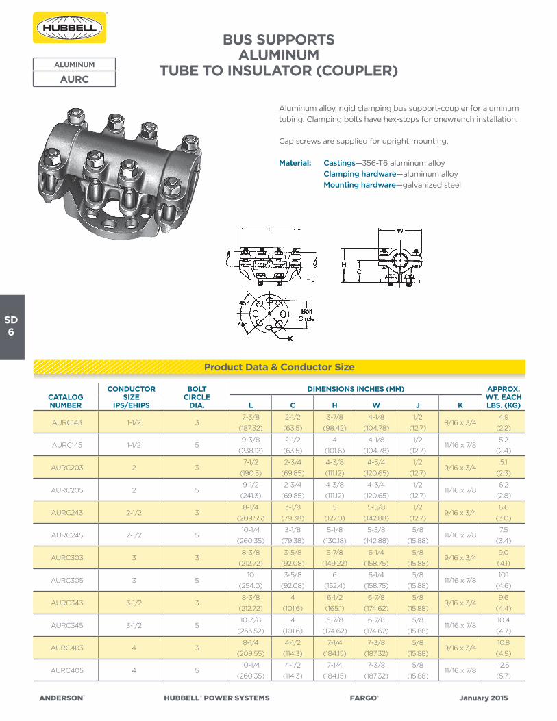
TUBE TO INSULATOR (COUPLER)ALUMINUM
AURC
Aluminum alloy, rigid clamping bus support-coupler for aluminum
tubing. Clamping bolts have hex-stops for onewrench installation.
Cap screws are supplied for upright mounting.
Material: Castings—356-T6 aluminum alloy
Clamping hardware—aluminum alloy
Mounting hardware—galvanized steel
CATALOG NUMBER
CONDUCTORSIZE
IPS/EHIPS
BOLTCIRCLE
DIA.
DIMENSIONS INCHES (MM) APPROX. WT. EACH LBS. (KG)L C H W J K
AURC143 1-1/2 37-3/8
(187.32)
2-1/2
(63.5)
3-7/8
(98.42)
4-1/8
(104.78)
1/2
(12.7)9/16 x 3/4
4.9
(2.2)
AURC145 1-1/2 59-3/8
(238.12)
2-1/2
(63.5)
4
(101.6)
4-1/8
(104.78)
1/2
(12.7)11/16 x 7/8
5.2
(2.4)
AURC203 2 37-1/2
(190.5)
2-3/4
(69.85)
4-3/8
(111.12)
4-3/4
(120.65)
1/2
(12.7)9/16 x 3/4
5.1
(2.3)
AURC205 2 59-1/2
(241.3)
2-3/4
(69.85)
4-3/8
(111.12)
4-3/4
(120.65)
1/2
(12.7)11/16 x 7/8
6.2
(2.8)
AURC243 2-1/2 38-1/4
(209.55)
3-1/8
(79.38)
5
(127.0)
5-5/8
(142.88)
1/2
(12.7)9/16 x 3/4
6.6
(3.0)
AURC245 2-1/2 510-1/4
(260.35)
3-1/8
(79.38)
5-1/8
(130.18)
5-5/8
(142.88)
5/8
(15.88)11/16 x 7/8
7.5
(3.4)
AURC303 3 38-3/8
(212.72)
3-5/8
(92.08)
5-7/8
(149.22)
6-1/4
(158.75)
5/8
(15.88)9/16 x 3/4
9.0
(4.1)
AURC305 3 510
(254.0)
3-5/8
(92.08)
6
(152.4)
6-1/4
(158.75)
5/8
(15.88)11/16 x 7/8
10.1
(4.6)
AURC343 3-1/2 38-3/8
(212.72)
4
(101.6)
6-1/2
(165.1)
6-7/8
(174.62)
5/8
(15.88)9/16 x 3/4
9.6
(4.4)
AURC345 3-1/2 510-3/8
(263.52)
4
(101.6)
6-7/8
(174.62)
6-7/8
(174.62)
5/8
(15.88)11/16 x 7/8
10.4
(4.7)
AURC403 4 38-1/4
(209.55)
4-1/2
(114.3)
7-1/4
(184.15)
7-3/8
(187.32)
5/8
(15.88)9/16 x 3/4
10.8
(4.9)
AURC405 4 510-1/4
(260.35)
4-1/2
(114.3)
7-1/4
(184.15)
7-3/8
(187.32)
5/8
(15.88)11/16 x 7/8
12.5
(5.7)
Product Data & Conductor Size
SD7
ANDERSON™ HUBBELL®POWERSYSTEMS FARGO® January2015
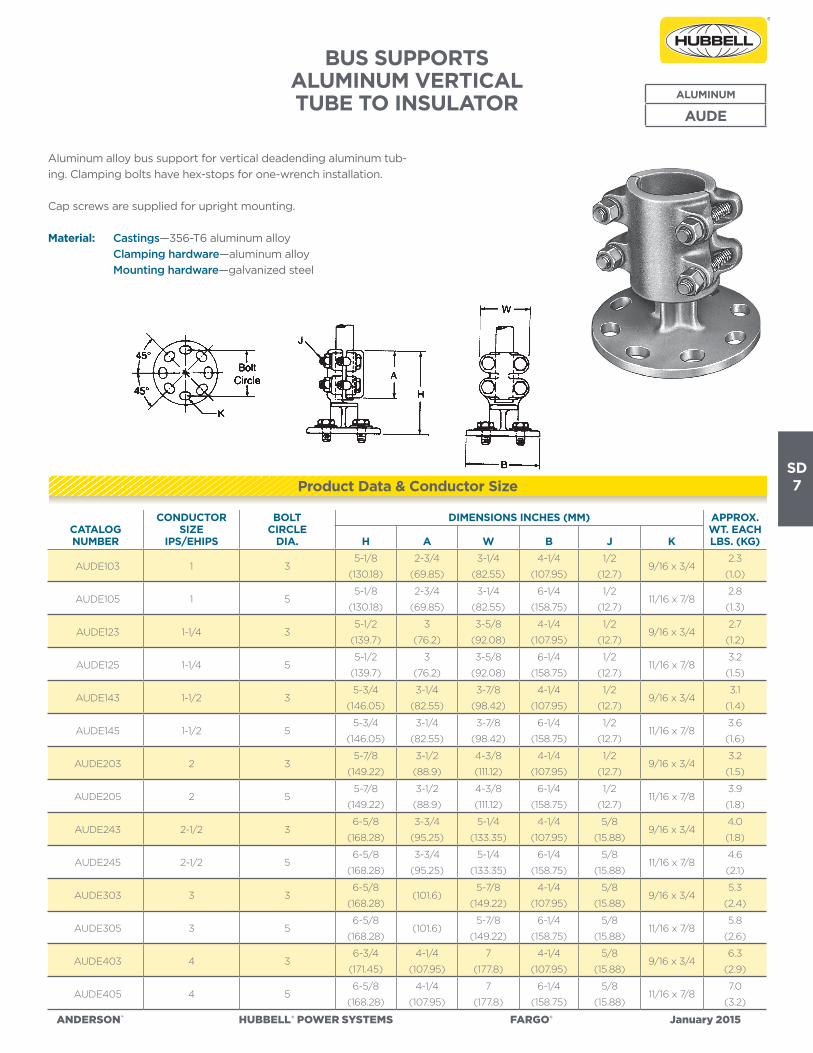
BUS SUPPORTSALUMINUM VERTICALTUBE TO INSULATOR
ALUMINUM
AUDE
Aluminum alloy bus support for vertical deadending aluminum tub-
ing. Clamping bolts have hex-stops for one-wrench installation.
Cap screws are supplied for upright mounting.
Material: Castings—356-T6 aluminum alloy
Clamping hardware—aluminum alloy
Mounting hardware—galvanized steel
CATALOG NUMBER
CONDUCTORSIZE
IPS/EHIPS
BOLTCIRCLE
DIA.
DIMENSIONS INCHES (MM) APPROX. WT. EACH LBS. (KG)H A W B J K
AUDE103 1 35-1/8
(130.18)
2-3/4
(69.85)
3-1/4
(82.55)
4-1/4
(107.95)
1/2
(12.7)9/16 x 3/4
2.3
(1.0)
AUDE105 1 55-1/8
(130.18)
2-3/4
(69.85)
3-1/4
(82.55)
6-1/4
(158.75)
1/2
(12.7)11/16 x 7/8
2.8
(1.3)
AUDE123 1-1/4 35-1/2
(139.7)
3
(76.2)
3-5/8
(92.08)
4-1/4
(107.95)
1/2
(12.7)9/16 x 3/4
2.7
(1.2)
AUDE125 1-1/4 55-1/2
(139.7)
3
(76.2)
3-5/8
(92.08)
6-1/4
(158.75)
1/2
(12.7)11/16 x 7/8
3.2
(1.5)
AUDE143 1-1/2 35-3/4
(146.05)
3-1/4
(82.55)
3-7/8
(98.42)
4-1/4
(107.95)
1/2
(12.7)9/16 x 3/4
3.1
(1.4)
AUDE145 1-1/2 55-3/4
(146.05)
3-1/4
(82.55)
3-7/8
(98.42)
6-1/4
(158.75)
1/2
(12.7)11/16 x 7/8
3.6
(1.6)
AUDE203 2 35-7/8
(149.22)
3-1/2
(88.9)
4-3/8
(111.12)
4-1/4
(107.95)
1/2
(12.7)9/16 x 3/4
3.2
(1.5)
AUDE205 2 55-7/8
(149.22)
3-1/2
(88.9)
4-3/8
(111.12)
6-1/4
(158.75)
1/2
(12.7)11/16 x 7/8
3.9
(1.8)
AUDE243 2-1/2 36-5/8
(168.28)
3-3/4
(95.25)
5-1/4
(133.35)
4-1/4
(107.95)
5/8
(15.88)9/16 x 3/4
4.0
(1.8)
AUDE245 2-1/2 56-5/8
(168.28)
3-3/4
(95.25)
5-1/4
(133.35)
6-1/4
(158.75)
5/8
(15.88)11/16 x 7/8
4.6
(2.1)
AUDE303 3 36-5/8
(168.28)(101.6)
5-7/8
(149.22)
4-1/4
(107.95)
5/8
(15.88)9/16 x 3/4
5.3
(2.4)
AUDE305 3 56-5/8
(168.28)(101.6)
5-7/8
(149.22)
6-1/4
(158.75)
5/8
(15.88)11/16 x 7/8
5.8
(2.6)
AUDE403 4 36-3/4
(171.45)
4-1/4
(107.95)
7
(177.8)
4-1/4
(107.95)
5/8
(15.88)9/16 x 3/4
6.3
(2.9)
AUDE405 4 56-5/8
(168.28)
4-1/4
(107.95)
7
(177.8)
6-1/4
(158.75)
5/8
(15.88)11/16 x 7/8
7.0
(3.2)
Product Data & Conductor Size

SD8
ANDERSON™ HUBBELL®POWERSYSTEMS FARGO® January2015
Designed for: ◊ ± 1-1/8” expansion, 80 ft. total maximum bus length (both sides), ◊◊ ± 2-1/8” expansion, 160 ft. total maximum bus length (both sides).
BUS SUPPORTSALUMINUM EXPANSION
TUBE TO INSULATOR
Aluminum alloy expansion bus support for aluminum tubing.
Clamping bolts have hex-stops for one-wrench installation.
Cap screws are supplied for upright mounting. Contact sealant is
recommended.
Material: Castings—356-T6 aluminum alloy
Factory formed laminated shunt—aluminum
Clamping hardware—aluminum alloy
Mounting hardware—galvanized steel
Note: To specify extra heavy (schedule 80 EHIPS) tubing,
add “H” to catalog number; Example: AURFH405.
Refer to chart DC-6536 on page SD-9 for installation instructions.
CATALOG NUMBER
CONDUCTORSIZE
IPS/EHIPS
BOLTCIRCLE
DIA.
DIMENSIONS INCHES (MM) APPROX. WT. EACH LBS. (KG)L C W Z J JJ K
AURF203 2 3◊16-7/8
(428.62)
2-3/4
(69.85)
4-1/4
(107.95)
3/4
(19.05)
1/2
(12.7)
1/2
(12.7)9/16 x 3/4
11.0
(5.0)
AURF205 2 5◊◊19-7/8
(504.82)
2-3/4
(69.85)
6-1/4
(158.75)
3/4
(19.05)
5/8
(15.88)
1/2
(12.7)11/16 x 7/8
11.8
(5.4)
AURF243 2-1/2 3◊17-1/2
(444.5)
3-1/8
(79.38)
4-1/4
(107.95)
3/4
(19.05)
1/2
(12.7)
5/8
(15.88)9/16 x 3/4
12.8
(5.8)
AURF245 2-1/2 5◊◊20-5/8
(523.88)
3-1/8
(79.38)
6-1/4
(158.75)
3/4
(19.05)
5/8
(15.88)
5/8
(15.88)11/16 x 7/8
13.7
(6.2)
AURF303 3 3◊17-3/4
(450.85)
3-5/8
(92.08)
4-1/4
(107.95)
13/16
(20.64)
1/2
(12.7)
5/8
(15.88)9/16 x 3/4
15.2
(6.9)
AURF305 3 5◊◊20-7/8
(530.22)
1/2
(101.6)
6-1/4
(158.75)
13/16
(20.64)
5/8
(15.88)
5/8
(15.88)11/16 x 7/8
16.3
(7.4)
AURF343 3-1/2 3◊18-1/4
(463.55)
4
(101.6)
1/2-1/4
(107.95)
1
(25.4)
1/2
(12.7)
5/8
(15.88)9/16 x 3/4
23.7
(10.8)
AURF345 3-1/2 5◊◊21-3/8
(542.92)
4-1/2
(114.3)
6-1/4
(158.75)
1
(25.4)
5/8
(15.88)
5/8
(15.88)11/16 x 7/8
25.3
(11.5)
AURF403 4 3◊18-1/4
(463.55)
4-1/2
(114.3)
4-1/4
(107.95)
1
(25.4)
1/2
(12.7)
5/8
(15.88)9/16 x 3/4
24.8
(11.3)
AURF405 4 5◊◊21-5/8
(549.28)
4
(101.6)
6-1/4
(158.75)
1-1/4
(31.75)
5/8
(15.88)
5/8
(15.88)11/16 x 7/8
24.6
(11.2)
AURF505 5 5◊◊23-5/8
(600.08)
4-7/8
(123.82)
6-1/4
(158.75)
1-1/4
(31.75)
5/8
(15.88)
5/8
(15.88)11/16 x 7/8
25.8
(11.7)
AURF605 6 5◊◊26-1/8
(663.58)
5-3/8
(136.52)
6-1/4
(158.75)
1-1/2
(38.1)
5/8
(15.88)
5/8
(15.88)11/16 x 7/8
26.3
(11.9)
Product Data & Conductor Size
ALUMINUM
AURF

SD9
ANDERSON™ HUBBELL®POWERSYSTEMS FARGO® January2015
INSTALLATION CHARTDC-6536
HOW TO USE CHART
1. Determine tubular bus temperature and locate this temperature on the “Temperature Reading
for ‘X’ Dimension” scale.
2. Locate the intersection of the given bus length and the temperature reading.
3. Read “X” dimension setting from this intersection point.
4. Determine “Y” dimension in a similar manner.
5. Determine “Z” dimension from applicable ANDERSON connector assembly. The location of
the tube-shunt body from the end of the tube may be determined by adding X + Y + Z.
6. Repeat this procedure for the tubular bus on the other side of the connector.
7. Do not exceed given bus length for each particular bolt circle.
SD10
ANDERSON™ HUBBELL®POWERSYSTEMS FARGO® January2015
CATALOG NUMBER
COPPER CONDUCTOR RANGE BOLTCIRCLE
DIA.
DIMENSIONS INCHES (MM) APPROX. WT. EACH LBS. (KG)CABLE CABLE DIA.
TUBINGIPS L C J K
ICA0253 #8 — 250 MCM.128- .575
(3.25- 14.60)1/8-1/4 3
1
(25.4)
5/8
(15.88)
3/8
(9.52)9/16 x 3/4
2.0
(.91)
ICA0255 #8 — 250 MCM.128- .575
(3.25- 14.60)1/8-1/4 5
1
(25.4)
1-1/8
(28.58)
3/8
(9.52)11/16 x 7/8
3.8
(1.72)
ICA1003 4/0 — 1000 MCM.460- 1.152
(11.68- 29.26)1/4-3/4 3
1
(25.4)
1
(25.4)
3/8
(9.52)9/16 x 3/4
2.5
(1.13)
ICA1005 4/0 — 1000 MCM.460- 1.152
(11.68- 29.26)1/4-3/4 5
1
(25.4)
1
(25.4)
3/8
(9.52)11/16 x 7/8
4.7
(2.13)
ICA2003 500 — 2000 MCM.811- 1.632
(20.60- 41.45)1/2-1-1/4 3
1
(25.4)
1
(25.4)
1/2
(12.7)9/16 x 3/4
2.9
(1.32)
ICA2005 500 — 2000 MCM.811- 1.632
(20.60- 41.45)1/2-1-1/4 5
1-1/4
(31.75)
1
(25.4)
1/2
(12.7)11/16 x 7/8
4.5
(2.04)
ICA3003 1000 — 3000 MCM1.152- 1.998
(29.26- 50.75)1-2 3
1-1/4
(31.75)
1-1/4
(31.75)
1/2
(12.7)9/16 x 3/4
3.4
(1.54)
ICA3005 1000 — 3000 MCM1.152- 1.998
(29.26- 50.75)1-2 5
1-1/4
(31.75)
1-1/4
(31.75)
1/2
(12.7)11/16 x 7/8
5.4
(2.45)
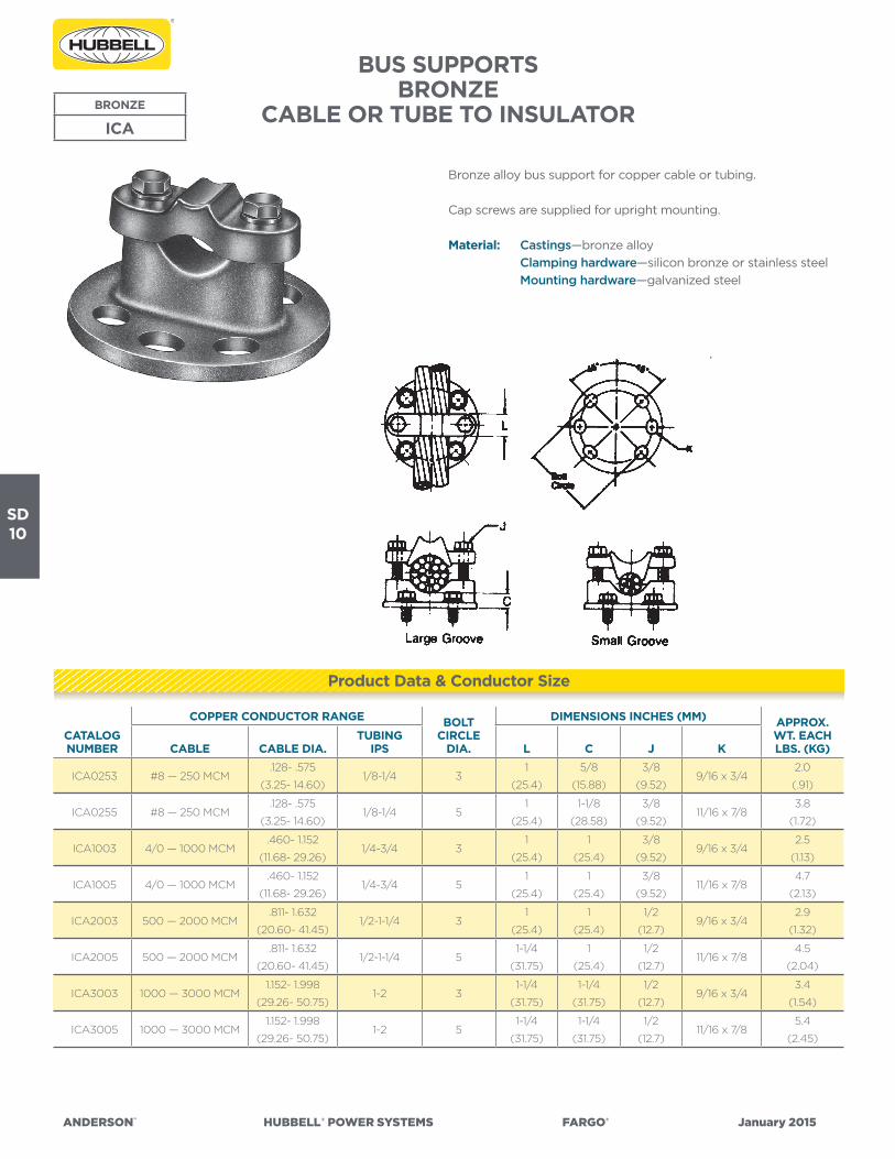
BUS SUPPORTSBRONZE
CABLE OR TUBE TO INSULATOR
Bronze alloy bus support for copper cable or tubing.
Cap screws are supplied for upright mounting.
Material: Castings—bronze alloy
Clamping hardware—silicon bronze or stainless steel
Mounting hardware—galvanized steel
BRONZE
ICA
Product Data & Conductor Size

SD11
ANDERSON™ HUBBELL®POWERSYSTEMS FARGO® January2015
CATALOG NUMBER
COPPER CONDUCTOR RANGE BOLTCIRCLE
DIA.
DIMENSIONS INCHES (MM) APPROX. WT. EACH LBS. (KG)CABLE CABLE DIA.
TUBINGIPS L H C W J K
CSSB403 #8 — 4/0 Str..128- .528
(3.25- 13.41)1/4 3
2-1/4
(57.15)
2-1/2
(63.5)
1-3/4
(44.45)
2-1/4
(57.15)
3/8
(9.52)9/16 x 3/4
1.2
(.54)
CSSB405 #8 — 4/0 Str..128- .528
(3.25- 13.41)1/4 5
2-1/4
(57.15)
2-1/2
(63.5)
1-3/4
(44.45)
2-1/4
(57.15)
3/8
(9.52)11/16 x 7/8
3.0
(1.36)
CSSB503 250 — 500 MCM.574- .813
(14.58- 20.65)3/8 -1/2 3
2-1/4
(57.15)
2-7/8
(73.02)
2
(50.8)
2-1/4
(57.15)
3/8
(9.52)9/16 x 3/4
1.8
(.82)
CSSB505 250 — 500 MCM.574- .813
(14.58- 20.65)3/8 -1/2 5
2-1/4
(57.15)
2-7/8
(73.02)
2
(50.8)
2-1/4
(57.15)
3/8
(9.52)11/16 x 7/8
3.3
(1.50)
CSSB753 550 — 750 MCM.853- .998
(21.67- 25.35)1/2 3
2-1/2
(63.5)
3
(76.2)
2-1/8
(53.98)
2-5/8
(66.68)
3/8
(9.52)9/16 x 3/4
2.9
(1.32)
CSSB755 550 — 750 MCM.853- .998
(21.67- 25.35)1/2 5
2-1/2
(63.5)
3
(76.2)
2-1/8
(53.98)
2-5/8
(66.68)
3/8
(9.52)11/16 x 7/8
3.8
(1.72)
CSSB1003 800 — 1000 MCM1.031- 1.152
(26.19- 29.26)3/4 3
2-1/2
(63.5)
3-3/8
(85.72)
2-3/8
(60.32)
2-3/4
(69.85)
3/8
(9.52)9/16 x 3/4
4.1
(1.86)
CSSB1005 800 — 1000 MCM1.031- 1.152
(26.19- 29.26)3/4 5
2-1/2
(63.5)
3-3/8
(85.72)
2-3/8
(60.32)
2-3/4
(69.85)
3/8
(9.52)11/16 x 7/8
6.1
(2.77)
CSSB1503 1250 — 1500 MCM1.288- 1.412
(32.72- 35.86)1 3
2-1/2
(63.5)
3-3/4
(95.25)
2-5/8
(66.68)
2-7/8
(73.02)
3/8
(9.52)9/16 x 3/4
6.4
(2.90)
CSSB1505 1250 — 1500 MCM1.288- 1.412
(32.72- 35.86)1 5
2-1/2
(63.5)
3-3/4
(95.25)
2-5/8
(66.68)
2-7/8
(73.02)
3/8
(9.52)11/16 x 7/8
6.7
(3.04)
CSSB2003 1500 — 2000 MCM1.411- 1.632
(35.84- 41.45)1 3
2-1/2
(63.5)
4
(101.6)
2-3/4
(69.85)
3
(76.2)
3/8
(9.52)9/16 x 3/4
4.7
(2.13)
CSSB2005 1500 — 2000 MCM1.411- 1.632
(35.84- 41.45)1 5
2-1/2
(63.5)
4
(101.6)
2-3/4
(69.85)
3
(76.2)
3/8
(9.52)11/16 x 7/8
6.7
(3.04)
CSSB2503 2000 — 2500 MCM1.630- 1.824
(41.40- 46.33)1-1/4 3
2-1/2
(63.5)
4-1/4
(107.95)
2-7/8
(73.02)
3-3/8
(85.72)
3/8
(9.52)9/16 x 3/4
4.7
(2.13)
CSSB2505 2000 — 2500 MCM1.630- 1.824
(41.40- 46.33)1-1/4 5
2-1/2
(63.5)
4-1/4
(107.95)
2-7/8
(73.02)
3-3/8
(85.72)
3/8
(9.52)11/16 x 7/8
6.5
(2.95)
BUS SUPPORTSBRONZE
CABLE OR TUBE TO INSULATOR
Heavy duty, bronze alloy bus support for copper cable or tubing.
Cap screws are supplied for upright mounting.
Material: Castings—bronze alloy
Clamping hardware—silicon bronze or stainless steel
Mounting hardware—galvanized steel
BRONZE
CSSB
Product Data & Conductor Size

SD12
ANDERSON™ HUBBELL®POWERSYSTEMS FARGO® January2015
CATALOG NUMBER
COPPER CONDUCTOR RANGE BOLT
CIRCLEDIA.
DIMENSIONS INCHES (MM) APPROX. WT. EACH LBS. (KG)CABLE
TUBINGIPS L H C W A J K
CDSB403 #8 — 4/0 Str. 1/8--1/4 32-1/4
(57.15)
3-1/4
(82.55)
2-1/4
(57.15)
3-3/4
(95.25)
1
(25.4)
3/8
(9.52)9/16 x 3/4
4.6
(2.09)
CDSB405 #8 — 4/0 Str. 1/8--1/4 52-1/4
(57.15)
3-1/4
(82.55)
2-1/4
(57.15)
3-3/4
(95.25)
1
(25.4)
3/8
(9.52)11/16 x 7/8
5.0
(2.27)
CDSB503 250 — 500 MCM 3/8 -1/2 32-1/4
(57.15)
3-1/4
(82.55)
2-3/8
(60.32)
3-5/8
(92.08)
1-1/4
(31.75)
3/8
(9.52)9/16 x 3/4
4.0
(1.81)
CDSB505 250 — 500 MCM 3/8 -1/2 52-1/4
(57.15)
3-1/4
(82.55)
2-3/8
(60.32)
3-5/8
(92.08)
1-1/4
(31.75)
3/8
(9.52)11/16 x 7/8
5.8
(2.63)
CDSB753 550 — 750 MCM 1/2 33
(76.2)
3-7/8
(98.42)
2-3/4
(69.85)
4-1/2
(114.3)
1-1/2
(38.1)
1/2
(12.7)9/16 x 3/4
7.8
(3.54)
CDSB755 550 — 750 MCM 1/2 53
(76.2)
3-7/8
(98.42)
2-3/4
(69.85)
4-1/2
(114.3)
1-1/2
(38.1)
1/2
(12.7)11/16 x 7/8
10.3
(4.67)
CDSB1003 800 — 1000 MCM 3/4 32-1/2
(63.5)
3-5/8
(92.08)
2-5/8
(66.68)
4-1/2
(114.3)
1-3/4
(44.45)
3/8
(9.52)9/16 x 3/4
5.1
(2.31)
CDSB1005 800 — 1000 MCM 3/4 52-1/2
(63.5)
3-5/8
(92.08)
2-5/8
(66.68)
4-1/2
(114.3)
1-3/4
(44.45)
3/8
(9.52)11/16 x 7/8
7.2
(3.26)
CDSB1503 1250 — 1500 MCM 1 32-1/2
(63.5)
3-7/8
(98.42)
2-3/4
(69.85)
4-7/8
(123.82)
1-7/8
(47.62)
3/8
(9.52)9/16 x 3/4
5.1
(2.31)
CDSB1505 1250 — 1500 MCM 1 52-1/2
(63.5)
3-7/8
(98.42)
2-3/4
(69.85)
4-7/8
(123.82)
1-7/8
(47.62)
3/8
(9.52)11/16 x 7/8
7.1
(3.22)
BUS SUPPORTSBRONZE
TWO CABLES OR TUBES TO INSULATOR
Heavy duty, bronze alloy bus support for two copper cables or
tubes.
Cap screws are supplied for upright mounting.
Material: Castings—bronze alloy
Clamping hardware—silicon bronze or stainless steel
Mounting hardware—galvanized steel
BRONZE
CDSB
Product Data & Conductor Size

SD13
ANDERSON™ HUBBELL®POWERSYSTEMS FARGO® January2015
CATALOG NUMBER
CONDUCTOR SIZEIPS
BOLTCIRCLE
DIA.
DIMENSIONS INCHES (MM) APPROX. WT. EACH LBS. (KG)L H C W J K
UP063 3/4 32
(50.8)
2-7/8
(73.02)
2
(50.8)
3
(76.2)
3/8
(9.52)9/16 x 3/4
3.7
(1.68)
UP065 3/4 52
(50.8)
3-1/8
(79.38)
2-1/4
(57.15)
3
(76.2)
3/8
(9.52)11/16 x 7/8
6.3
(2.86)
UP103 1 32
(50.8)
3
(76.2)
2
(50.8)
3-1/4
(82.55)
3/8
(9.52)9/16 x 3/4
3.8
(1.72)
UP105 1 52
(50.8)
3-1/4
(82.55)
2-1/4
(57.15)
3-1/4
(82.55)
3/8
(9.52)11/16 x 7/8
6.4
(2.90)
UP123 1-1/4 32-3/4
(69.85)
3-1/2
(88.9)
2-1/4
(57.15)
4
(101.6)
1/2
(12.7)9/16 x 3/4
5.4
(2.45)
UP125 1-1/4 52-3/4
(69.85)
3-5/8
(92.08)
2-3/8
(60.32)
4
(101.6)
1/2
(12.7)11/16 x 7/8
7.9
(3.58)
UP143 1-1/2 33
(76.2)
4
(101.6)
2-1/2
(63.5)
4-1/4
(107.95)
1/2
(12.7)9/16 x 3/4
6.3
(2.86)
UP145 1-1/2 53
(76.2)
4
(101.6)
2-1/2
(63.5)
4-1/4
(107.95)
1/2
(12.7)11/16 x 7/8
8.5
(3.86)
UP203 2 33
(76.2)
4-3/8
(111.12)
2-3/4
(69.85)
4-7/8
(123.82)
1/2
(12.7)9/16 x 3/4
6.4
(2.90)
UP205 2 53
(76.2)
4-3/8
(111.12)
2-3/4
(69.85)
4-7/8
(123.82)
1/2
(12.7)11/16 x 7/8
9.0
(4.08)
UP243 2-1/2 33
(76.2)
5
(127.0)
3-1/8
(79.38)
5-5/8
(142.88)
1/2
(12.7)9/16 x 3/4
7.8
(3.54)
UP245 2-1/2 53
(76.2)
5
(127.0)
3-1/8
(79.38)
5-5/8
(142.88)
1/2
(12.7)11/16 x 7/8
9.9
(4.49)
UP303 3 33
(76.2)
5-7/8
(149.22)
3-5/8
(92.08)
6-3/4
(171.45)
5/8
(15.88)9/16 x 3/4
9.9
(4.49)
UP305 3 53
(76.2)
5-7/8
(149.22)
3-5/8
(92.08)
6-3/4
(171.45)
5/8
(15.88)11/16 x 7/8
12.1
(5.49)
UP343 3-1/2 33-1/4
(82.55)
6-1/2
(165.1)
4
(101.6)
7-1/2
(190.5)
5/8
(15.88)9/16 x 3/4
12.2
(5.53)
UP345 3-1/2 53-1/4
(82.55)
6-1/2
(165.1)
4
(101.6)
7-1/2
(190.5)
5/8
(15.88)11/16 x 7/8
14.6
(6.62)
UP403 4 33-1/2
(88.9)
7-1/4
(184.15)
4-1/2
(114.3)
8
(203.2)
5/8
(15.88)9/16 x 3/4
14.7
(6.68)
UP405 4 53-1/2
(88.9)
7-1/4
(184.15)
4-1/2
(114.3)
8
(203.2)
5/8
(15.88)11/16 x 7/8
17.5
(7.85)
BUS SUPPORTSBRONZE
TUBE TO INSULATORBronze alloy bus support for copper tubing. Slip-free or rigid clamping
can be obtained by rotating cap 180 degrees. Static eliminator springs
are standard.
Cap screws are supplied for upright mounting.
Material: Castings—bronze alloy
Clamping hardware—silicon bronze or stainless steel
Mounting hardware—galvanized steel
Spring—stainless steel
BRONZE
UP
Product Data & Conductor Size

SD14
ANDERSON™ HUBBELL®POWERSYSTEMS FARGO® January2015
CATALOG NUMBER
CONDUCTOR SIZEIPS
BOLTCIRCLE
DIA.
DIMENSIONS INCHES (MM) APPROX. WT. EACH LBS. (KG)H A W J K
UDE063 3/4 35
(127.0)
3-1/8
(79.38)
2-1/2
(63.5)
3/8
(9.52)9/16 x 3/4
4.6
(2.09)
UDE103 1 35
(127.0)
3-1/8
(79.38)
2-7/8
(73.02)
3/8
(9.52)9/16 x 3/4
5.3
(2.40)
UDE105 1 55
(127.0)
3-1/8
(79.38)
2-7/8
(73.02)
3/8
(9.52)11/16 x 7/8
6.1
(2.77)
UDE123 1-1/4 34-3/4
(120.65)
2-7/8
(73.02)
3-5/8
(92.08)
1/2
(12.7)9/16 x 3/4
5.8
(2.63)
UDE125 1-1/4 54-3/4
(120.65)
2-7/8
(73.02)
3-5/8
(92.08)
1/2
(12.7)11/16 x 7/8
6.5
(2.95)
UDE143 1-1/2 35-1/4
(133.35)
3-1/8
(79.38)
3-3/4
(95.25)
1/2
(12.7)9/16 x 3/4
6.3
(2.86)
UDE145 1-1/2 55-1/4
(133.35)
3-1/8
(79.38)
3-3/4
(95.25)
1/2
(12.7)11/16 x 7/8
9.0
(4.08)
UDE203 2 35-7/8
(149.22)
3-5/8
(92.08)
4-3/8
(111.12)
1/2
(12.7)9/16 x 3/4
9.5
(4.31)
UDE205 2 55-7/8
(149.22)
3-5/8
(92.08)
4-3/8
(111.12)
1/2
(12.7)11/16 x 7/8
9.8
(4.44)
BUS SUPPORTSBRONZE VERTICAL
TUBE TO INSULATOR
Bronze alloy bus support for vertical deadending copper tubing. Clamping bolts have hex-stops for one-wrench installation.
Cap screws are supplied for upright mounting.
Material: Castings—bronze alloy Clamping hardware—silicon bronze or stainless steel Mounting hardware—galvanized steel
BRONZE
UDE
Product Data & Conductor Size
SD15
ANDERSON™ HUBBELL®POWERSYSTEMS FARGO® January2015
CATALOG NUMBER
FLAT BAR SIZEINCHES
BOLTCIRCLE
DIA.
DIMENSIONS INCHES (MM) APPROX. WT. EACH LBS. (KG)L C T W J K
BHX403T 4 35-7/8
(149.22)
2-1/2
(63.5)*
5-7/8
(149.22)
1/2
(12.7)9/16 x 3/4
8.0
(3.63)
BHX405T 4 55-7/8
(149.22)
2-1/2
(63.5)*
5-7/8
(149.22)
1/2
(12.7)11/16 x 7/8
10.5
(4.76)
BHX503T 5 36-7/8
(174.62)
2-1/2
(63.5)*
6-7/8
(174.62)
1/2
(12.7)9/16 x 3/4
10.9
(4.94)
BHX603T 6 38-1/4
(209.55)
2-1/2
(63.5)*
8-1/4
(209.55)
5/8
(15.88)9/16 x 3/4
14.9
(6.76)
BHX605T 6 58-1/4
(209.55)
2-1/2
(63.5)*
8-1/4
(209.55)
5/8
(15.88)11/16 x 7/8
17.3
(7.85)
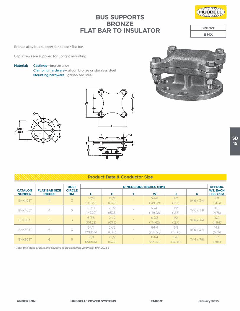
BUS SUPPORTSBRONZE
FLAT BAR TO INSULATOR
Bronze alloy bus support for copper flat bar.
Cap screws are supplied for upright mounting.
Material: Castings—bronze alloy
Clamping hardware—silicon bronze or stainless steel
Mounting hardware—galvanized steel
BRONZE
BHX
* Total thickness of bars and spacers to be specified. Example: BHX20334
Product Data & Conductor Size

SD16
ANDERSON™ HUBBELL®POWERSYSTEMS FARGO® January2015
CATALOG NUMBER
FLAT BAR SIZEINCHES
BOLTCIRCLE
DIA.
DIMENSIONS INCHES (MM) APPROX. WT. EACH LBS. (KG)L H C T J K
BVXA403T 4 33-7/8
(98.42)
8
(203.2)
3
(76.2)*
1/2
(12.7)9/16 x 3/4
8.9
(4.04)
BVXA503T 5 34-7/8
(123.82)
9
(228.6)
3
(76.2)*
1/2
(12.7)9/16 x 3/4
9.7
(4.40)
BVXA505T 5 54-7/8
(123.82)
9
(228.6)
3
(76.2)*
1/2
(12.7)11/16 x 7/8
12.9
(5.85)
BVXA603T 6 36-1/4
(158.75)
10-3/8
(263.52)
3
(76.2)*
5/8
(15.88)9/16 x 3/4
18.3
(8.30)
BUS SUPPORTSBRONZE VERTICAL SLIP TYPE
FLAT BAR TO INSULATOR
Bronze alloy, slide type bus support for copper flat bar. Roller
allows ± 5/8” bus expansion.
Cap screws are supplied for upright mounting.
Material: Castings—bronze alloy
Clamping hardware—silicon bronze or stainless steel
Mounting hardware—galvanized steel
Roller—stainless steel
BRONZE
BVXA
* Total thickness of bars and spacers to be specified. Example: BVXA403112
Product Data & Conductor Size

SD17
ANDERSON™ HUBBELL®POWERSYSTEMS FARGO® January2015
CATALOG NUMBER
FLAT BAR SIZE BOLTCIRCLE
DIA.
DIMENSIONS INCHES (MM) APPROX. WT. EACH LBS. (KG)MAIN TAP L H C T J K
BVX403T 4 2 33-7/8
(98.42)
8
(203.2)
3
(76.2)*
1/2
(12.7)9/16 x 3/4
8.8
(3.99)
BVX405T 4 2 55-3/4
(146.05)
7-7/8
(200.02)
3
(76.2)*
1/2
(12.7)11/16 x 7/8
10.1
(4.58)
BVX503T 5 3 34-3/4
(120.65)
8-7/8
(225.42)
3
(76.2)*
1/2
(12.7)9/16 x 3/4
9.4
(4.26)
BVX603T 6 4 36-1/4
(158.75)
10-1/4
(260.35)
3-1/8
(79.38)*
5/8
(15.88)9/16 x 3/4
16.3
(7.39)
BVX605T 6 4 56
(152.4)
10-3/8
(263.52)
3-1/8
(79.38)*
5/8
(15.88)11/16 x 7/8
17.6
(7.98)
BUS SUPPORTSBRONZE VERTICAL RIGIDFLAT BAR TO INSULATOR
Bronze alloy bus support for copper flat bar.
Cap screws are supplied for upright mounting.
Material: Castings—bronze alloy
Clamping hardware—silicon bronze or stainless steel
Mounting hardware—galvanized steel
BRONZE
BVX
* Total thickness of bars and spacers to be specified; example: BVX4031
Product Data & Conductor Size

SD18
ANDERSON™ HUBBELL®POWERSYSTEMS FARGO® January2015
ALUMINUM WELDMENT CONNECTORS
INTRODUCTION
Welded joints of aluminum conductors offer advantages over
bolted and compression fittings in performance and economy for
certain applications. This is especially true when the proper weld-
ing method (MIG or TIG) and the proper weldment connectors
are selected.
The best electrical joints are obtained when quality connectors of
proven performance, that are backed by a reputable connector
manufacturer, are installed with the proper welding methods.
Electric arc welding, with an inert gas shield, provides electrically
and mechanically sound joints that require no special surface
preparation other than cleaning of the joint to be welded. There
is no contact resistance in a properly welded joint. The result-
ing connection is highly efficient and adds very little bulk to the
conductors.
From an economic standpoint, welded joints are more feasible
in larger substations that can justify the services of experienced
welders and the use of the proper welding apparatus. Practi-
cally all types of joints for joining aluminum angle bar, sheet and
tubular bus are possible through the use of proper welding acces-
sories. It is also practical to weld tubular bus to cable and cable
terminal joints through proper welding techniques and cable
connectors. Of course, proper provision must be made to free the
cable of high stresses in the vicinity of the weld because of the
annealed conductor strands.
Many techniques have been developed for the welded assembly
of aluminum conductors in substations, but certain ones have
been found to offer more advantages than others. Accessories
in the form of cast aluminum weldment connectors have been
developed to facilitate the joining and supporting of aluminum
conductors. These connectors, as developed by Anderson, have
been designed to provide:
1. Rigid support and proper alignment.
2. Fast assembly without need for tedious forming and fitting
of bus.
3. Continuous welds of regular contours that provide a weld
area equivalent to 1-10% of the cross sectional area of the
connector.
4. Neat appearance without bulky additions beyond the size
and shape of the conductors.
5. Smooth contours suitable for high voltage applications
where corona and R.I.V. level are of concern.
6. Flexible couplers to compensate for expansion and contrac-
tion of bus.
7. Many other features available for specific applications.
Anderson supplies cast weldment fittings of 356 aluminum alloy
which are heat treated to T6 condition for applications requir-
ing high strength and good electrical conductivity. It is wise to
choose the filler alloy on the basis of the parent metal alloys to be
joined. A poor choice can cause various difficulties, i.e.,
1. Low strength.
2. Weld cracking.
3. Poor corrosion resistance.
4. Poor color matching.
5. Difficulty in welding.
The filler rod material recommended by Anderson for joining
356-T6 cast aluminum fittings to EC grade aluminum conductor
materials is 4043 alloy. This filler material has a typical conductiv-
ity of 40 per cent (IACS). Although it would appear that a purer
material should be used for welding aluminum castings and the
EC grades of conductor materials, the resulting joint usually has
a lower resistance than an equivalent length of conductor. Also, a
further point for consideration is that 4043 alloy is considerably
easier to weld than the higher purity filler materials.
For more information on Welding Methods and Apparatus, see reference section ST.
SD19
ANDERSON™ HUBBELL®POWERSYSTEMS FARGO® January2015
CATALOG NUMBER
ALUMINUM CONDUCTOR SIZEIPS /EHIPS
BOLTCIRCLE
DIA.
DIMENSIONS INCHES (MM) APPROX. WT. EACH LBS. (KG)L C W K
WURE103 1 36-1/2
(165.1)
2
(50.8)
3
(76.2)9/16 x 3/4
1.5
(.68)
WURE123 1-1/4 36-1/2
(165.1)
2-1/2
(63.5)
3
(76.2)9/16 x 3/4
1.7
(.77)
WURE143 1-1/2 36-1/2
(165.1)
2-1/2
(63.5)
3
(76.2)9/16 x 3/4
1.7
(.77)
WURE145 1-1/2 59-1/8
(231.78)
2-1/2
(63.5)
3
(76.2)11/16 x 7/8
2.3
(1.04)
WURE203 2 36-1/2
(165.1)
2-3/4
(69.85)
3-1/4
(82.55)9/16 x 3/4
2.5
(1.13)
WURE205 2 59-1/8
(231.78)
2-3/4
(69.85)
3-1/4
(82.55)11/16 x 7/8
3.0
(1.36)
WURE243 2-1/2 36-1/2
(165.1)
3-1/8
(79.38)
3-3/4
(95.25)9/16 x 3/4
2.8
(1.27)
WURE245 2-1/2 59-1/8
(231.78)
3-1/8
(79.38)
3-3/4
(95.25)11/16 x 7/8
3.2
(1.45)
WURE303 3 36-1/2
(165.1)
3-5/8
(92.08)
4-1/2
(114.3)9/16 x 3/4
2.7
(1.22)
WURE305 3 59-1/8
(231.78)
3-5/8
(92.08)
4-1/2
(114.3)11/16 x 7/8
3.4
(1.54)
WURE343 3-1/2 36-1/2
(165.1)
4
(101.6)
5-1/4
(133.35)9/16 x 3/4
4.2
(1.90)
WURE345 3-1/2 59-1/8
(231.78)
4
(101.6)
5-1/4
(133.35)11/16 x 7/8
4.7
(2.13)
WURE403 4 36-1/2
(165.1)
4-1/2
(114.3)
5- 5/8
(142.88)9/16 x 3/4
3.9
(1.77)
WURE405 4 59-3/8
(238.12)
4-1/2
(114.3)
5- 5/8
(142.88)11/16 x 7/8
5.7
(2.58)
WURE505 5 59-3/8
(238.12)
4-7/8
(123.82)
6-3/4
(171.45)11/16 x 7/8
6.1
(2.77)
WURE605 6 59-7/8
(250.82)
5- 3/8
(136.52)
7-3/4
(196.85)11/16 x 7/8
6.9
(3.13)
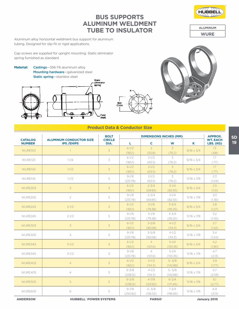
BUS SUPPORTSALUMINUM WELDMENT
TUBE TO INSULATORAluminum alloy horizontal weldment bus support for aluminum
tubing. Designed for slip-fit or rigid applications.
Cap screws are supplied for upright mounting. Static eliminator
spring furnished as standard.
Material: Castings—356-T6 aluminum alloy
Mounting hardware—galvanized steel
Static spring—stainless steel
ALUMINUM
WURE
Product Data & Conductor Size

SD20
ANDERSON™ HUBBELL®POWERSYSTEMS FARGO® January2015
CATALOG NUMBER
ALUMINUM CONDUCTOR SIZE
IPS /EHIPS
BOLTCIRCLE
DIA.
DIMENSIONS INCHES (MM) APPROX. WT. EACH LBS. (KG)L C W J K
WTH103 1 36-3/4
(171.45)
2
(50.8)
3
(76.2)
1/2
(12.7)9/16 x 3/4
2.2
(2.0)
WTH105 1 59-3/8
(238.12)
2-1/4
(57.15)
3
(76.2)
5/8
(15.88)11/16 x 7/8
2.7
(1.22)
WTH123 1-1/4 36-3/4
(171.45)
2-1/4
(57.15)
3-1/4
(82.55)
1/2
(12.7)9/16 x 3/4
2.0
(.91)
WTH125 1-1/4 59-3/8
(238.12)
2-3/8
(60.32)
3-1/4
(82.55)
5/8
(15.88)11/16 x 7/8
2.3
(1.04)
WTH143 1-1/2 36-3/4
(171.45)
2-1/2
(63.5)
3-1/2
(88.9)
1/2
(12.7)9/16 x 3/4
2.04
(1.09)
WTH145 1-1/2 59-3/8
(238.12)
2-1/2
(63.5)
3-1/2
(88.9)
5/8
(15.88)11/16 x 7/8
3.2
(1.45)
WTH203 2 36-3/4
(171.45)
2-3/4
(69.85)
4
(101.6)
1/2
(12.7)9/16 x 3/4
2.5
(1.13)
WTH205 2 59-3/8
(238.12)
2-3/4
(69.85)
4
(101.6)
5/8
(15.88)11/16 x 7/8
3.7
(1.68)
WTH243 2-1/2 36-3/4
(171.45)
3-1/8
(79.38)
4-1/2
(114.3)
1/2
(12.7)9/16 x 3/4
2.6
(1.18)
WTH245 2-1/2 59-3/8
(238.12)
3-1/8
(79.38)
4-1/2
(114.3)
5/8
(15.88)11/16 x 7/8
3.8
(1.72)
WTH303 3 36-3/4
(171.45)
3-5/8
(92.08)
5-1/2
(139.7)
1/2
(12.7)9/16 x 3/4
3.0
(1.36)
WTH305 3 59-3/8
(238.12)
3-5/8
(92.08)
5-1/2
(139.7)
5/8
(15.88)11/16 x 7/8
4.1
(1.86)
WTH343 3-1/2 36-3/4
(171.45)
4
(101.6)
5-7/8
(149.22)
1/2
(12.7)9/16 x 3/4
2.7
(1.22)
WTH345 3-1/2 59-3/8
(238.12)
4
(101.6)
5-7/8
(149.22)
5/8
(15.88)11/16 x 7/8
3.6
(1.63)
WTH403 4 39-1/8
(231.78)
4-1/2
(114.3)
6-1/2
(165.1)
1/2
(12.7)9/16 x 3/4
3.9
(1.77)
WTH405 4 59-3/8
(238.12)
4-1/2
(114.3)
6-1/2
(165.1)
5/8
(15.88)11/16 x 7/8
4.8
(2.18)
WTH407 4 711-3/4
(298.45)
4-1/2
(114.3)
6-1/2
(165.1)
5/8
(15.88)13/16 x 1
5.5
(10.6)
BUS SUPPORTS ALUMINUM WELDMENTTUBE TO INSULATOR
Aluminum alloy horizontal weldment bus support for aluminum
tubing. Designed for slip-fit or rigid applications.
Cap screws are supplied for upright mounting. Static eliminator
spring furnished as standard.
Material: Castings—356-T6 aluminum alloy
Mounting hardware—galvanized steel
Static spring—stainless steel
ALUMINUM
WTH
Continued on next page.
Product Data & Conductor Size

SD21
ANDERSON™ HUBBELL®POWERSYSTEMS FARGO® January2015
CATALOG NUMBER
ALUMINUM CONDUCTOR SIZE
IPS /EHIPS
BOLTCIRCLE
DIA.
DIMENSIONS INCHES (MM) APPROX. WT. EACH LBS. (KG)L C W J K
WTH503 5 39-3/8
(238.12)
4-7/8
(123.82)
7-7/8
(200.02)
1/2
(12.7)9/16 x 3/4
4.6
(2.09)
WTH505 5 59-3/8
(238.12)
4-7/8
(123.82)
7-7/8
(200.02)
5/8
(15.88)11/16 x 7/8
5.0
(2.27)
WTH507 5 711-3/4
(298.42)
4-7/8
(123.82)
7-7/8
(200.02)
3/4
(19.05)13/16 x 1
5.7
(2.58)
WTH603 6 39-3/8
(238.12)
5-3/8
(136.52)
9-1/8
(231.78)
1/2
(12.7)9/16 x 3/4
4.9
(2.22)
WTH605 6 59-3/8
(238.12)
5-3/8
(136.52)
9-1/8
(231.78)
5/8
(15.88)11/16 x 7/8
5.7
(2.58)
WTH607 6 711-3/4
(298.42)
5-3/8
(136.52)
9-1/8
(231.78)
3/4
(19.05)13/16 x 1
6.9
(3.13)
BUS SUPPORTSALUMINUM WELDMENT
TUBE TO INSULATOR(CONTINUED)
Product Data & Conductor Size

SD22
ANDERSON™ HUBBELL®POWERSYSTEMS FARGO® January2015
CATALOG NUMBER
ALUMINUM CONDUCTOR SIZE
IPS
BOLTCIRCLE
DIA.
DIMENSIONS INCHES (MM) APPROX. WT. EACH LBS. (KG)L C Z W K
WURF203 2 3 ◊11
(279.4)
2-3/4
(69.85)
3/4
(19.05)
12-3/8
(314.32)9/16 x 3/4
7.7
(3.49)
WURF205 2 5 ◊◊14-1/8
(358.78)
2-3/4
(69.85)
3/4
(19.05)
13
(330.2)11/16 x 7/8
9.1
(4.13)
WURF243 2-1/2 3 ◊11
(279.4)
3-1/8
(79.38)
3/4
(19.05)
10-5/8
(269.88)9/16 x 3/4
7.8
(3.54)
WURF245 2-1/2 5 ◊◊14-1/8
(358.78)
3-1/8
(79.38)
3/4
(19.05)
12-7/8
(327.02)11/16 x 7/8
9.9
(4.49)
WURF303 3 3 ◊11
(279.4)
3-5/8
(92.08)
13/16
(20.64)
13-3/8
(339.72)9/16 x 3/4
11.2
(5.08)
WURF305 3 5 ◊◊14-1/8
(358.78)
3-5/8
(92.08)
13/16
(20.64)
15-7/8
(403.22)11/16 x 7/8
12.6
(5.72)
WURF343 3-1/2 3 ◊11
(279.4)
4
(101.6)
1
(25.4)
14
(355.6)9/16 x 3/4
18.4
(8.35)
WURF345 3-1/2 5 ◊◊14-1/8
(358.78)
4
(101.6)
1
(25.4)
14-3/8
(365.12)11/16 x 7/8
21.9
(9.93)
WURF403 4 3 ◊11
(279.4)
4-1/2
(114.3)
1
(25.4)
14-3/4
(374.65)9/16 x 3/4
20.8
(9.43)
WURF405 4 5 ◊◊14-3/8
(365.12)
4-1/2
(114.3)
1-1/4
(31.75)
17
(431.8)11/16 x 7/8
19.8
(8.98)
WURF503 5 3 ◊11-1/2
(292.1)
4-7/8
(123.82)
1-1/4
(31.75)
17
(431.8)9/16 x 3/4
27.4
(12.43)
WURF505 5 5 ◊◊14-3/8
(365.12)
4-7/8
(123.82)
1-1/4
(31.75)
18-1/8
(460.38)11/16 x 7/8
23.1
(10.48)
WURF605 6 5 ◊◊14-7/8
(377.82)
5-3/8
(136.52)
1-1/2
(38.1)
19-1/4
(488.95)11/16 x 7/8
32.7
(14.83)
BUS SUPPORTSALUMINUM WELDMENT EXPANSION
TUBE TO INSULATOR
Aluminum alloy, horizontal weldment, expansion bus support
for aluminum tubing. Add “H” to catalog number (WURFH) if
schedule 80 EHIPS tubing is to be used. Static eliminator spring is
furnished as standard.
Cap screws are supplied for upright mounting.
Material: Castings—356-T6 aluminum alloy
Factory formed laminated shunt—aluminum
Hardware—galvanized steel
Static spring—stainless steel
ALUMINUM
WURF
Designed for ◊ ± 1-1/8” expansion, 80 ft. maximum total bus length (both sides) ◊ ◊ ± 2-1/8” expansion, 160 ft. maximum total bus length (both sides)
Refer to chart DC-6536 on page SD-9 for installation instructions.
Product Data & Conductor Size

SD23
ANDERSON™ HUBBELL®POWERSYSTEMS FARGO® January2015
CATALOG NUMBER
ALUMINUM CONDUCTOR SIZE
IPS/EHIPS
BOLTCIRCLE
DIA.
DIMENSIONS INCHES (MM) APPROX. WT.
EACH LBS. (KG)L C J K
WUDE123 1-1/4 32-7/8
(73.02)
1-7/8
(47.62)
1/2
(12.7)9/16 x 3/4
1.6
(.72)
WUDE143 1-1/2 33-3/8
(85.72)
2-1/8
(53.98)
1/2
(12.7)9/16 x 3/4
1.9
(.86)
WUDE203 2 34
(101.6)
2-1/4
(57.15)
1/2
(12.7)9/16 x 3/4
2.1
(.95)
WUDE205 2 54
(101.6)
2-1/4
(57.15)
5/8
(15.88)11/16 x 7/8
3.2
(1.45)
WUDE243 2-1/2 34-1/2
(115.4)
2-1/2
(63.5)
1/2
(12.7)9/16 x 3/4
2.5
(1.13)
WUDE245 2-1/2 54-1/2
(115.4)
2-1/2
(63.5)
5/8
(15.88)11/16 x 7/8
3.4
(1.54)
WUDE303 3 35
(127.0)
2-1/2
(63.5)
1/2
(12.7)9/16 x 3/4
2.7
(1.22)
WUDE305 3 55
(127.0)
2-1/2
(63.5)
5/8
(15.88)11/16 x 7/8
3.8
(1.72)
WUDE343 3-1/2 34-3/4
(120.65)
2-3/4
(69.85)
1/2
(12.7)9/16 x 3/4
3.5
(1.59)
WUDE345 3-1/2 54-3/4
(120.65)
2-3/4
(69.85)
5/8
(15.88)11/16 x 7/8
4.5
(2.04)
WUDE403 4 35
(127.0)
2-3/4
(69.85)
1/2
(12.7)9/16 x 3/4
3.9
(1.77)
WUDE405 4 55
(127.0)
2-3/4
(69.85)
5/8
(15.88)11/16 x 7/8
5.0
(2.27)
WUDE505 5 55-1/4
(133.35)
2-3/4
(69.85)
5/8
(15.88)11/16 x 7/8
6.5
(2.95)
BUS SUPPORTSALUMINUM WELDMENT
TUBE TO INSULATOR
Aluminum alloy, vertical weldment bus support for tubing. Cap
screws are supplied for upright mounting.
Material: Castings—356-T6 aluminum alloy
Hardware—galvanized steel
ALUMINUM
WUDE
Product Data & Conductor Size